Stanley Convergent Security Solutions SONICLASS Sonitrol iClass Keypad User Manual FCC Part 15
Stanley Convergent Security Solutions, Inc. Sonitrol iClass Keypad FCC Part 15
Manual

Certification Exhibit
FCC ID: 2ACWM-SONICLASS
IC: 7309A-SONICLASS
FCC Rule Part: 15.209
IC Radio Standards Specification: RSS-210
ACS Project: 14-2086
Manufacturer: Stanley Convergent Security Solutions, Inc.
Model: SONIP ICLASS KP
User Manual
3998 FAU Blvd. Suite 310 Boca Raton, FL 33431 Tel: 561-961-5585 Fax: 561-961-5587
Installation Guide
Standard and iCLASS Enhanced Keypad
19810009 Rev D
September 2014
Stanley Convergent Security Solutions, Suite 500, 1707 Orlando Central Parkway, Orlando, FL 32809, U.S.A
Tel +1 877 SONITROL (+1 877 766-4876) Web www.Sonitrol.com

Standard and iCLASS Enhanced Keypad 19810009 Rev D
Copyrights and Trademarks
Copyright Information
Copyright © 1998-2014 by Stanley Security Solutions
All rights reserved. No part of this work covered by the copyright hereon may be reproduced or used in any form
or by any means graphic, electronic, or mechanical, including photocopying, recording, taping, or information
storage and retrieval systems without permission of Stanley Security Solutions.
Trademarks
Sonitrol is a Registered Trademark of Stanley Security Solutions.
All other products are trademarks of their respective manufacturers. All registered and unregistered trademarks
are the sole property of their respective companies.
Related Publications
The table below contains related Sonitrol documents with corresponding part numbers.
Description Part Number
iBase Installation Guide 19810005
FlexIP Installation Guide 19810065
FlexiBase Installation Guide 19810022
Panel Programming Guide 19810015
Keypad User Guide 19810016
History of Changes:
Date Summary of Changes
8/27/14 Updated FCC IC information, and iCLASS mounting instructions
Page ii

19810009 Rev D Standard and iCLASS Enhanced Keypad
Table of Contents
1. Introduction.................................................................................................................................... 1
1.1 Copyright and Trademark .......................................................................................................... 1
1.2 Reference Material .................................................................................................................... 1
1.3 Overview .................................................................................................................................... 1
2. Hardware ........................................................................................................................................ 2
2.1 Opening Case ........................................................................................................................... 2
2.2 Wall Mounting ............................................................................................................................ 2
2.3 Single Gang Box Mounting ........................................................................................................ 3
2.4 Terminal Block Mounting ........................................................................................................... 4
2.5 Keypad Wiring ........................................................................................................................... 4
2.6 Cabling Considerations ............................................................................................................. 5
2.7 Closing Case ............................................................................................................................. 5
2.8 Specifications ............................................................................................................................ 5
3. FCC ................................................................................................................................................. 6
4. SONITROL CORPORATION HARDWARE LIMITED WARRANTY STATEMENT ...................... 8
Page iii

Standard and iCLASS Enhanced Keypad 19810009 Rev D
This page is intentionally left blank.
Page iv
19810009 Rev D Standard and iCLASS Enhanced Keypad
1. Introduction
1.1 Copyright and Trademark
Copyright 2008 by Sonitrol Corporation. All rights reserved.
No part of this document may be reproduced or distributed in any form or by any means, or stored
in a database or retrieval system, without the prior written permission of Sonitrol Corporation.
1.2 Reference Material
This manual covers the information needed to install the SonIP Standard and iCLASS Enhanced
Keypads. See 19810016 SonIP Keypad User Guide for user options and service procedures. See
19810005 SonIP iBase Installation Guide or 19810022 FlexiBase Installation Guide for complete
planning and additional installation procedures. See 19810015 SonIP iBase/FlexiBase
Programming Guide for options and programming procedures.
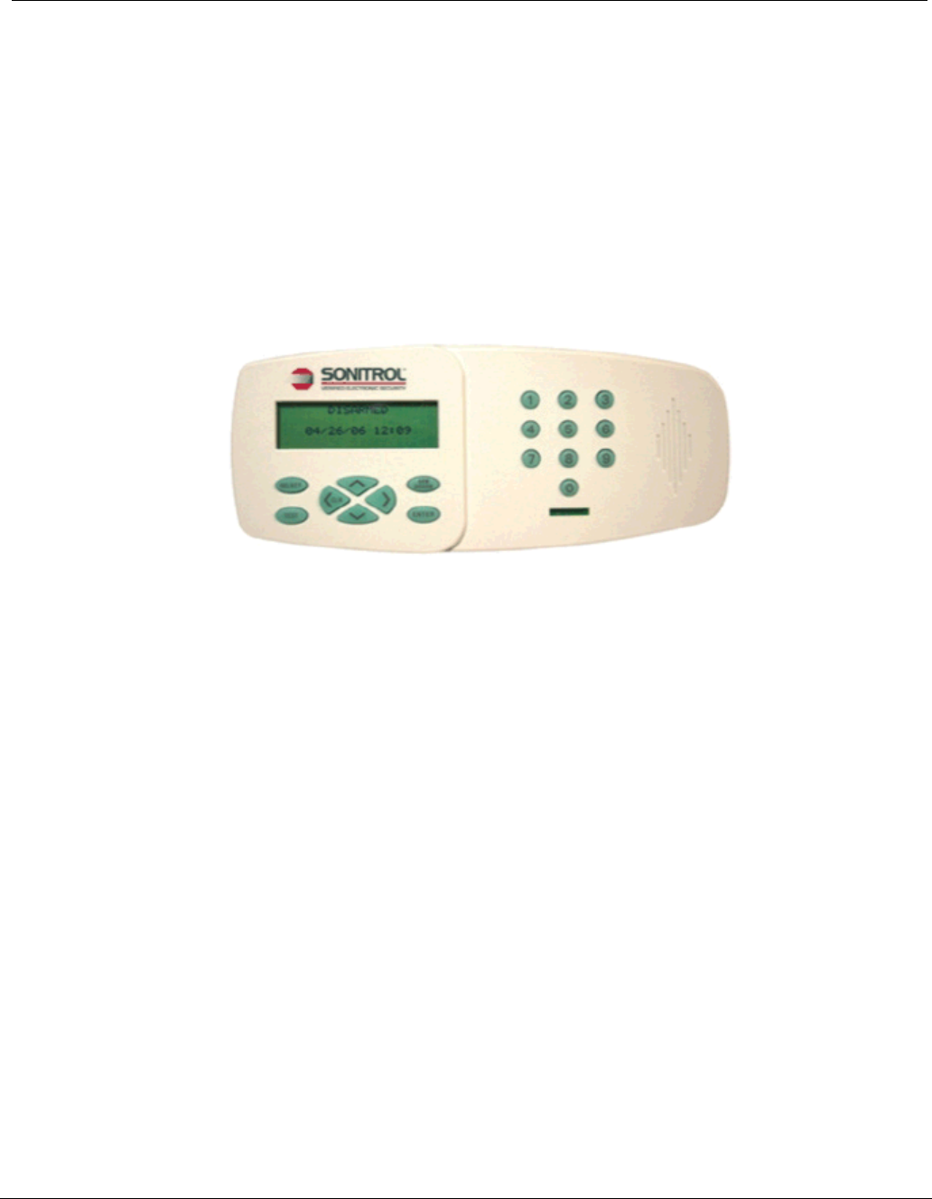
1.3 Overview
The Standard and Enhanced Keypads are compatible with the SonIP iBase and FlexiBase
Systems. The two keypads have the same system and programming functionality.
The iCLASS Enhanced Keypad has an integrated HID iCLASS reader that can be configured as an
Arm/ Disarm reader or ingress access control.
The Standard/Enhanced Keypad is the primary user interface for navigating system programming,
performing simple data entry, and controlling the SonIP iBase and FlexiBase System alarms and
access control functions. A Liquid Crystal Display (LCD), with scrolling text, is provided for
displaying data entry, system status messages, programming menus, and function options. These
can be accessed and selected through the alphanumeric digital keypad. The LCD display is backlit
and the keypad is low level illuminated, or in case of poor lighting conditions, may be programmed
for high level illumination. The LCD backlight remains illuminated at the normal brightness at all
times except when a button has been pressed The keypad high level illumination remains active for
15 seconds after the last key press. The keypad can be mounted up to 100m (328 ft.) from the
control panel, nearest module, or power hub.
Note: If a keypad needs to be located more than 100m (328 ft.) from the previous device, a Power
Hub module must be installed in a convenient location so that the 100m (328 ft.) limitation is
observed for all peripheral bus wire runs.
Page 1
Standard and iCLASS Enhanced Keypad 19810009 Rev D
2. Hardware
Each Keypad is shipped with the following hardware
• (2) RJ-45 male crimp connectors
CAUTION: You must be free of static electricity before handling circuit boards. It is
recommended that you wear a grounding strap or touch a bare metal surface to discharge
static electricity.
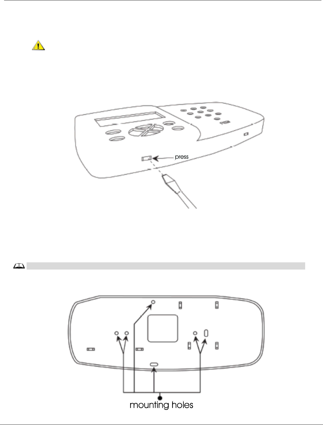
2.1 Opening Case
Depress tabs on bottom of case using a small slotted screwdriver. The case should pop off once the
second tab is depressed. The board will be located in front cover.
Figure 1. Depress Tab with slotted screwdriver
2.2 Wall Mounting
The Standard and iCLASS Enhanced keypad backplate has several mounting hole locations (see
Figure 2). For wall mounting use two of the middle mounting holes.
Note
FCC Compliance requirement - All iCLASS Keypads must be installed with metal backbox with EMT
conduit runs back to control panel. (Does not apply to Standard Keypad).
Figure 2. Backplate Mounting Holes
Page 2
19810009 Rev D Standard and iCLASS Enhanced Keypad
Place keypad backplate with straight edge or flat side up level on wall. Using a level, hold the
backplate against the wall and mark the mounting holes. Mount the backplate using the appropriate
hardware. The slotted mounting holes can be used to level during installation.
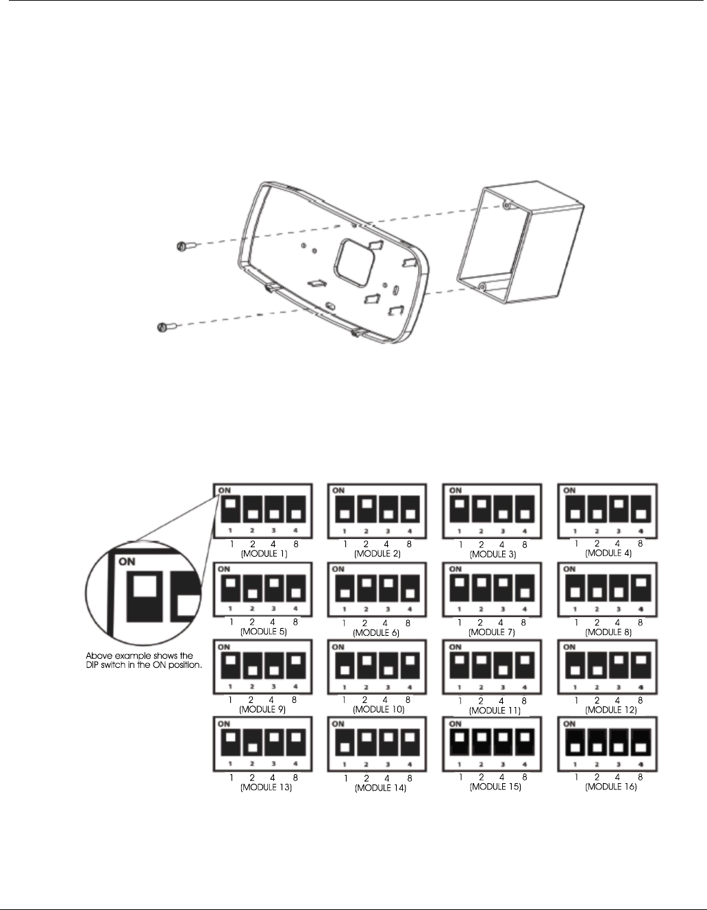
2.3 Single Gang Box Mounting
You can mount the Standard or iCLASS Enhanced keypad directly to a single gang outlet box,
either horizontally or vertically, depending on the orientation of the gang box.
Note: Be aware that the backplate may not completely cover the box.
Recommended wire gauges for typical keypad installations are 16-18 AWG.
Figure 3. Gang Box Mounting
Dip Switch Settings: Determine the appropriate address for this module and set the address
switches as follows:
Note: On Dip switch 1 (labeled DPSW1 on PCA) slide the switch to the ON position for a 1 and to
the OFF position for a 0.
Figure 4. Dip Switch Addresses
Note: The addresses of the Keypads correspond to the number of keypads in the system. The dip
switch addresses also represent the last octet of the modules IP address (192.168.60.1 –
192.168.60.16). To address the keypad use consecutive numbers from 1-16. Do not duplicate
address switch settings.
Page 3
Standard and iCLASS Enhanced Keypad 19810009 Rev D
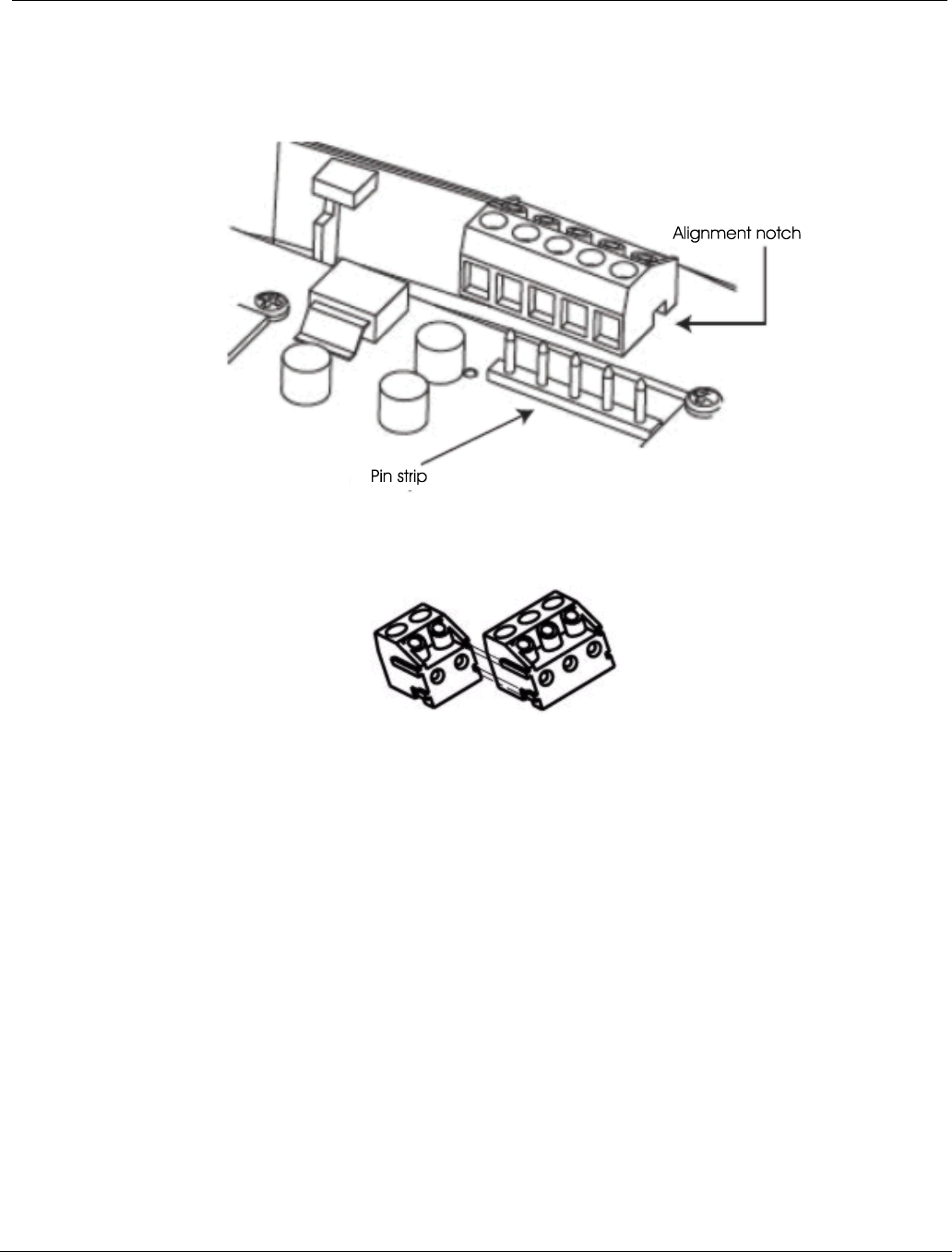
2.4 Terminal Block Mounting
1. The terminal blocks are removable for wiring. They are not directional and can be installed
incorrectly. Re-install by aligning the correct number of positions terminal block over the pins
and the slot over the pin strip and pressing down.
Figure 5. Mounting Terminal Block on Board
2. If the terminal blocks become separated they can easily be reassembled by sliding the grooved
edge into the receiving slot on the other piece.
Figure 6. Terminal Block Assembly
2.5 Keypad Wiring
Remove keypad terminal block and connect appropriate wires. To ensure proper connections, each
connection is silk-screened on the keypad circuit board. The keypad connections at the control
panel must match connections at Keypad.
• J3:
– +12V, Positive power supply input connection for Keypad
– GND, Negative power supply input connection for Keypad
– BEEPOUT, Open Collector Output for sounding an external sounder or driving an
external LED
Note: UL requires that there be NO CONNECTION to this output, which goes low while
the keypad is beeping.
– +12V, Positive power supply output connection for Keypad
– GND, Negative power supply output connection for Keypad
• J1:
– LAN IN - Peripheral Bus Data Connections
• J2:
– LAN OUT - Peripheral Bus Data Connections
Page 4

19810009 Rev D Standard and iCLASS Enhanced Keypad
2.6 Cabling Considerations
If a keypad needs to be located more than 100m (328 ft.) from the previous device, a Power Hub
module must be installed in a convenient location so that the 100m (328 ft.) limitation is observed
for all peripheral bus wire runs.
• Sonitrol recommends that you use CAT 5, 5e, 6 or 6e cable when running Standard and
iCLASS Enhanced keypad cables.
• DO NOT run cables parallel to AC wiring, unless the AC is in metallic conduit.
• Avoid mounting the keypad next to a light switch or electrical outlet.
• Keep wires away from fluorescent light fixtures. Fluorescent lights produce a high level of
electrical noise.
• Keep cables away from high current devices (i.e., motors, welders, etc.) which might induce
spikes into the wires.
Attach the Standard or iCLASS Enhanced keypad to the backplate after completing all wiring and
checks
2.7 Closing Case
Insert upper tabs into slots and press bottom of keypad in until lower tabs snap into place. You
should hear a click when case is properly closed.
2.8 Specifications
• Supply voltage: 12-14 VDC
• Dimensions:
– iCLASS: 9.5" W x 4.5" H (24.1cm x 11.4 cm)
– Standard: 8" W x 4.5" H (20.3 cm x 11.4 cm)
• Operating Temperature: 32 to 122oF (0 to 50oC)
• Humidity: 93% non-condensing
• Patent: Pending
• Current consumption on:
– Standard Keypad: 275mA max
– iCLASS Keypad: 375mA max
• UL Listings:
– UL 294 - Access Control System Units
– UL 365 - Police Station Connected Burglar Alarm Units and Systems
– UL 609 - Local Burglar Alarm Units and Systems
– UL 1076 - Proprietary Burglar Alarm Units and Systems
– UL 1610 - Central-Station Burglar-Alarm Units
– UL 1635 - Digital Alarm Communicator System Units
• ULC Listings:
– CAN/ULC-S303-M91 - Local Burglar Alarm Units and Systems
– CAN/ULC - S304-06 - Signal Receiving Center and Premise Burglar Alarm Control Units
- Active Level = A1 minimum risk for ULC
– CSA C22.2 No 205 - Signal Equipment
– ULC/ORD-C1076-86 - Proprietary Burglar Alarm Units and Systems
Page 5

Standard and iCLASS Enhanced Keypad 19810009 Rev D
3. FCC
Warning: Changes or modifications to this device not expressly approved by Stanley Security Solutions could void the user’s
authority to operate the equipment.
Note: This equipment has been tested and found to comply with the limits for a Class B digital device, pursuant to Part 15
of the FCC Rules. These limits are designed to provide reasonable protection against harmful interference in a
residential installation. This equipment generates, uses, and can radiate radio frequency energy and, if not installed
and used in accordance with the instructions, may cause harmful interference to radio communications. However,
there is no guarantee that interference will not occur in a particular installation. If this equipment does cause harmful
interference to radio or television reception, which can be determined by turning the equipment off and on, the user
is encouraged to try to correct the interference by one or more of the following measures:
• Reorient or relocate the receiving antenna.
• Increase the separation between the equipment and receiver.
• Connect the equipment into an outlet on a circuit different from that to which the receiver is connected.
• Consult the dealer or an experienced radio/TV technician for help.
FCC ID: 2ACWM-SONICLASS
THIS DEVICE COMPLIES WITH PART 15 OF THE FCC RULES. OPERATION IS SUBJECT TO THE FOLLOWING
TWO CONDITIONS: (1) THIS DEVICE MAY NOT CAUSE HARMFUL INTERFERENCE, AND (2) THIS DEVICE MUST
ACCEPT ANY INTERFERENCE RECEIVED, INCLUDING INTERFERENCE THAT MAY CAUSE UNDESIRED
OPERATION. IN COMPLIANCE WITH FCC REQUIREMENT 15.27 NO SPECIAL ACCESSORIES ARE REQUIRED
IN ORDER TO COMPLY WITH PART 15 OF THE FCC REGULATIONS. CHANGES OR MODIFICATIONS NOT
EXPRESSLY APPROVED BY SONITROL COULD VOID THE USER’S AUTHORITY TO OPERATE THE
EQUIPMENT.
This equipment complies with FCC radiation exposure limits set forth for an uncontrolled environment. This equipment
is in direct contact with the body of the user under normal operating conditions. This transmitter must not be co-located
or operating in conjunction with any other antenna or transmitter.
Page 6

19810009 Rev D Standard and iCLASS Enhanced Keypad
4. IC
Note: Under Industry Canada regulations, this radio transmitter may only operate using an antenna of a type and
maximum (or lesser) gain approved for the transmitter by Industry Canada. To reduce potential radio interference to
other users, the antenna type and its gain should be so chosen that the equivalent isotropically radiated power
(e.i.r.p.) is not more than that necessary for successful communication.
Conformément à la réglementation d'Industrie Canada, le présent émetteur radio peut fonctionner avec une antenne
d'un type et d'un gain maximal (ou inférieur) approuvé pour l'émetteur par Industrie Canada. Dans le but de réduire
les risques de brouillage radioélectrique à l'intention des autres utilisateurs, il faut choisir le type d'antenne et son
gain de sorte que la puissance isotrope rayonnée équivalente (p.i.r.e.) ne dépasse pas l'intensité nécessaire à
l'établissement d'une communication satisfaisante.
This device complies with Industry Canada licence-exempt RSS standard(s). Operation is subject to the following
two conditions: (1) this device may not cause interference, and (2) this device must accept any interference,
including interference that may cause undesired operation of the device.
Le présent appareil est conforme aux CNR d'Industrie Canada applicables aux appareils radio exempts de licence.
L'exploitation est autorisée aux deux conditions suivantes : (1) l'appareil ne doit pas produire de brouillage, et (2)
l'utilisateur de l'appareil doit accepter tout brouillage radioélectrique subi, même si le brouillage est susceptible d'en
compromettre le fonctionnement.
IC ID: 7309A-SONICLASS
This Class B digital apparatus complies with Canadian ICES-003.
Cet appareil numérique de la classe B est conforme à la norme NMB-003 du Canada.
Canadian Point of Contact
David P. Jones, President / Paul A. Nickel, Vice President
Sonitrol Distribution Canada, Inc.
5875 Kennedy Road
Mississauga, Ontario L4Z 2G3
Canada
Tel: +1 905-890 7727
Page 7

Standard and iCLASS Enhanced Keypad 19810009 Rev D
5. SONITROL CORPORATION HARDWARE LIMITED
WARRANTY STATEMENT
Sonitrol Corporation warrants each new product of its manufacture, to be free from defects in material and
workmanship. It will repair or replace defective parts for a period of 24 months from the date of manufacture,
providing the equipment has not been subjected to abnormal conditions such as misuse, abuse, misapplication,
alteration, lightning damage or damage by an Act of God. This excludes packing, handling and shipping charges
from the Customer. The limited warranty is restricted to the original purchaser.
ALL OTHER WARRANTIES, EXPRESSED OR IMPLIED, INCLUDING MERCHANT ABILITY, THE FITNESS OF
EQUIPMENT FOR A PARTICULAR PURPOSE OR WITH RESPECT TO CLAIMS OF ANY THIRD PARTY BY
THE WAY OF INFRINGEMENT OR THE LIKE, ARE EXCLUD
Page 8