Stanley InnerSpace SYSTEM100 RF ID System User Manual System 100 User Guide R8
Stanley InnerSpace RF ID System System 100 User Guide R8
Users Manual Revised

System 100
User Guide
Publication No. SYUG-1

Service Hotline: 800.922.5966
System 100 User Guide Publication No. SYUG-1
2
Table of Contents
1.0 Power
1.1 Plugging in the Cart ………………………………………………………………… 4
1.2 Back-Up Battery……………………………………………………………………… 5
1.3 Replacing Fuses……………………………………………………………………... 6
2.0 RFID and Inventory Devices
2.1 Barcode Scanner……………………………………………………………………. 7
2.2 RFID Tags……………………………………………………………………………. 7
2.3 Network Connectivity………………………………………………………………... 7
2.4 Read Performance…………………………………………………………………… 7
2.5 Scan Interval………………………………………………………………………….. 7
2.6 RF-Enabled Shelves………………………………………………………………….8
2.7 Global Brain and Interconnect (GBI)………………………………………………..8
3.0 Security/Access Controls
3.1 Key Lock……………………………………………………………………………….. 8
3.2 Access Control Module (ACM)…………………………………………………… 8-9
3.3 Door Sensing…………………………………………………………………………. 9
4.0 Communications
4.1 Menu Screen on Access Control Module…………………………………………..9
5.0 Centralized Data Collection and Reporting
5.1 Software Interface……………………………………………………………………. 9
5.2 Network……………………………………………………………………………….. 9
5.3 Configuration…………………………………………………………………………. 9
6.0 Cart Status and Diagnostics
6.1 Warranty……………………………………………………………………………9-10
6.2 Error Rectification……………………………………………………………………10
6.3 RF-Enabled Shelves………………………………………………………………...10
7.0 spaceTRAX Information Engine
7.1 RFID Tags…………………………………………………………………………. 11
7.2 Applying and Associating RFID Tags…………………………………………… 11
7.3 Adding/Removing Tagged Items………………………………………………. 11
7.4 Available Reports…………………………………………………………………. 11
7.5 Enrolling Authorized Users………………………………………………………....12
7.6 Deactivating Authorized Users……………………………………………………..12
8.0 Notes to the Customer……………………………………………………………………...12

Service Hotline: 800.922.5966
System 100 User Guide Publication No. SYUG-1
3
SYSTEM 100 USER GUIDE
Thank you for selecting InnerSpace’s System 100™ to secure, track and manage your high cost
clinical supplies. System 100 consists of a cart with integrated RFID technology and biometric
access control, an enrollment station, a hand-held RFID reader, a hand-held barcode scanner,
RFID tags and a web-based information engine (marketed under the brand name spaceTRAX®).
Access to the cart is controlled and monitored via a biometric security system. RFID tags are
affixed to the outside package of clinical supplies and linked with the item’s barcode. RFID
antennae embedded in the cart’s shelves are constantly communicating with the RFID tags to track
the disposition, location, and expiration date of supplies. Coupling biometric security and RFID
technology connects the “Who”, “What”, “When” and “Where” which are essential elements in
achieving 100% charge capture.
Service Hotline: 800.922.5966
System 100 User Guide Publication No. SYUG-1
4
1.0 Power
1.1 Plugging in the Cart
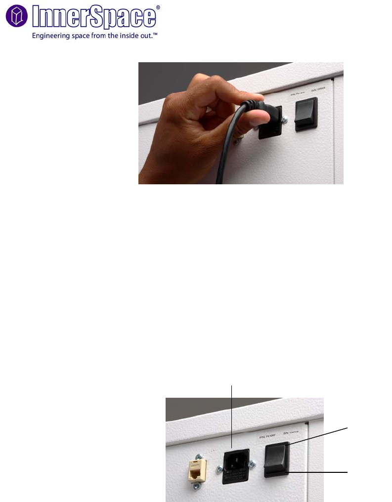
Recessed IEC C-14 connector located on the top, rear of the cart
15’ (457.2 cm) power cord and cord wrap
Requires an 100-240 VAC 50-60Hz electrical outlet
The LCD screen on the Access Control Module will read “ready” when cart has power
Power Supply Module is located at the top of the cart beneath the access panel to the
left of the global brain and interconnect. Note that only service personnel should have
access to this area and this should not be accessed by the general public. Always
disconnect AC power cord prior to removing access panel.
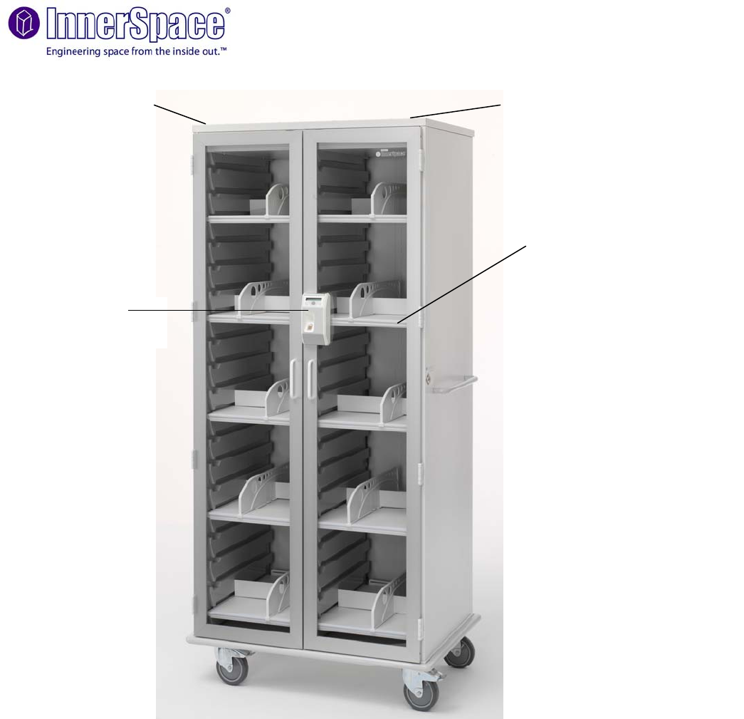
Power Supply
Module (PSM) Global Brain and Interconnect
Module (GBI)
RF-Enabled Shelf
Access Control
Module
Service Hotline: 800.922.5966
System 100 User Guide Publication No. SYUG-1
5
1.2 Back-Up Battery
LCD will show text message indicating the cart is running on battery power
Allows the cart to be unplugged and moved without loss of information or security
Housed under the top access panel. Note that only service personnel should have
access to this area and this should not be accessed by the general public. Always
disconnect AC power cord prior to removing access panel.
Life expectancy is 3 years and can operate the cart for a maximum of 3 hours
Recharging the battery takes 18 hours (from fully discharged)
A rocker switch on the back, upper right-hand section of the cart turns the back-up
battery on and off. Note that this switch disconnects the DC voltages from the GBI and
leaves the AC power active.
In the event that the battery completely discharges, the cart will unlock. This means the
cart will no longer scan and will be unlocked
To replace the battery, remove the top access panel and remove the battery which is
secured by Velcro straps. Note that only service personnel should have access to this
area and this should not be performed by the general public. Always disconnect AC
power cord prior to removing access panel.
ON
OFF
AC Power
Connector
Service Hotline: 800.922.5966
System 100 User Guide Publication No. SYUG-1
6
1.3 Replacing Fuses
Always disconnect AC power cord prior to replacing fuses.
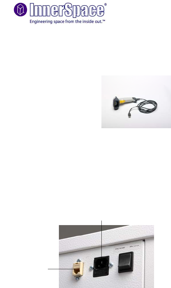
Fuses are located in two areas. a) Below the AC Power Connector (shown below) and
b) In the Power Supply Module
Replacing AC Power Connector Fuses
A quantity of two (2) AC power fuses is located in the slide-out compartment below the
female power connector. Remove the black cover to gain access to the fuses and
replace them with Fast Acting, 250V 3Amp (5mm x 20mm) fuses manufactured by
Bussmann (Part# GMA-3-R) or an equivalent supplier.
To replace the battery fuse located on the Power Supply Module remove the access
panel located on the top of the cart. Note that only service personnel should have
access to this area and this should not be performed by the general public. Always
disconnect AC power cord prior to removing access panel.
The fuse is located in a fuse holder that is connected to the positive terminal of the
battery (FUSE BLADE 10A 32V ATO FAST-ACT, Mfg: Littelfuse, Part#
0257010.PXPV).
Back-up
battery
Remove to
expose fuses
Service Hotline: 800.922.5966
System 100 User Guide Publication No. SYUG-1
7
2.0 RFID and Inventory Devices
2.1 Barcode Scanner
Reads the UPC barcodes from the inventory and sends the information thru the network
to spaceTRAX
2.2 RFID Tags
High frequency, passive RFID tags are to be affixed to the bottom of the inventory item
so that they will be read by the shelf
One tag is required per item.
Additional RFID tags can be ordered at any time
2.3 Network Connectivity
Ethernet port 10/100 base-T, RJ-45 connector located on the top rear of the cart
adjacent to the power connector
.
2.4 Read Performance
100% read performance when the tag on the bottom of the product is parallel with the
shelf, using the pre-approved tag models and non-metallic packaging
2.5 Scan Interval
Doors must be closed for scan of RFID tags to occur
Depending upon the number of items, the cart can take up to 5 minutes to complete a
full scan
A new scan is always triggered by closing the cart door
Should the door open during a scan, the scan will forcibly conclude
AC Power
Connector
Ethernet Port

Service Hotline: 800.922.5966
System 100 User Guide Publication No. SYUG-1
8
2.6 RF-Enabled Shelves
Each shelf has a single RJ-45 port for connection to the Global Brain (GBI) module via
a shielded CAT 5E cable
Shelves can be repositioned in the field. With the power off, the user can reposition
shelves as well as add shelves.
Standard carts come with ten (10) shelves each with one divider. The maximum
number of shelves per cart is sixteen (16).
2.7 Global Brain and Interconnect (GBI)
Located at the top of the cart beneath the access panel is a tamper-proof white box with
black handles on both sides. Note that only service personnel should have access to
this area and this should not be accessed by the general public. Always disconnect AC
power cord prior to removing access panel. There are several port connections on the
GBI (AC+ battery status, door sensors, lock module, access control module, key switch,
shelves, network, USB, and DC 12V)
All connections are quick-disconnect type and are keyed for ease in serviceability
Accessed by a removable enclosure panel (removal of two screws required to move the
panel)
3.0 Security/Access Controls
3.1 Key Lock
Standard key lock on every cart
Serves as an emergency manual override
Three setting: locked, open and auto. Carts in the locked mode can not be opened with
out the key. Carts in the open mode are not locked and can be opened freely. Carts in
the auto lock mode are controlled by the Access Control Module (ACM)
Lock Module is located at the top of the cart near in front of the GBI
3.2 Access Control Module (ACM)
Located on the front right door and attached with four screws
Uses an embedded fingerprint identification system
Maximum storage capacity is 188 fingerprint templates

Service Hotline: 800.922.5966
System 100 User Guide Publication No. SYUG-1
9
LCD display has back lighting to enhance viewing. Menu and select buttons are for
local information and diagnostics.
Allows access to the cart when an enrolled (i.e., authorized) user places their finger on
the ACM reader. Non-enrolled individuals are denied access to the cart.
To properly function, the key lock must to be set to the auto position
• Reports access log to spaceTRAX indicating the individual that accessed the cart and
the time that the doors opened and closed.
3.3 Door Sensing
Door movement (opening and closing) is monitored by door sensors.
4.0 Communications
4.1 Menu Screen on Access Control Module
Diagnostics for serviceability
5.0 Centralized Data Collection and Reporting
5.1 Software Interface
RFID carts use the same interface as spaceTRAX v2.0 – refer to the spaceTRAX v2.0
User Guide.
5.2 Network
Network can be static or dynamic IP and is customer-specified and pre-programmed
with the default setting as dynamic.
Network proxy settings are pre-programmed and customer-specified
5.3 Configuration
Cart configuration is done prior to shipping. Any remaining preferences are set during
initial implementation and in conjunction with the hospital’s IT staff.
6.0 Cart Status and Diagnostics
Service Hotline: 800.922.5966
System 100 User Guide Publication No. SYUG-1
10
6.1 Warranty
The cart components are serviced as needed under the lease agreement
6.2 Error Rectification
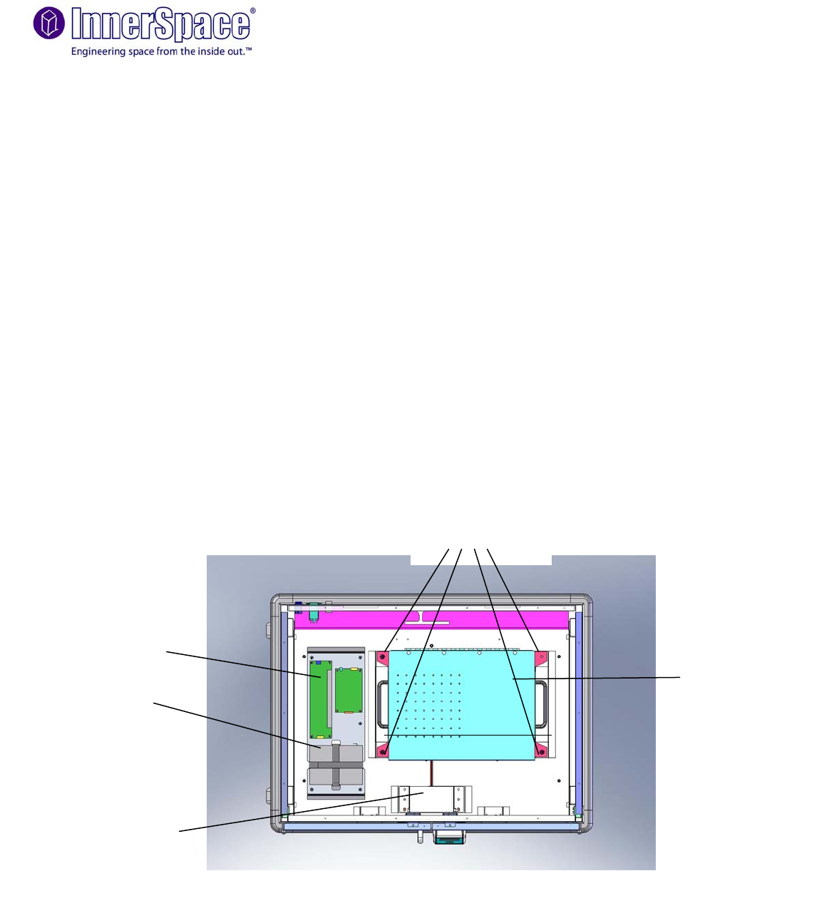
In the event of an error, the four major technological components of the cart are
designed to be easily removed for return to InnerSpace
A replacement item will be shipped as soon as possible (normally within a 24 hour time
period). "IMPORTANT NOTE: Components described below should be installed by
service personnel only.
To remove the ACM open the door of the cart and remove the four screws securing the
module to the door. Ship entire module back to InnerSpace
To remove the GBI open the top access panel (loosen two screws on top and slide the
panel off the top of the cart), remove four thumbscrews at GBI corners, unattached all
cables from the ports, lift the GBI module out of the cart using the two side handles.
There should be no need to open the GBI itself, simply ship it in its entirety back to
InnerSpace. Note that only service personnel should have access to this area and this
should not be performed by the general public. Always disconnect AC power cord prior
to removing access panel.
To remove the PSM or Lock module open the top access panel and remove from the
cart. Note that only service personnel should have access to this area and this should
not be performed by the general public. Always disconnect AC power cord prior to
removing access panel.
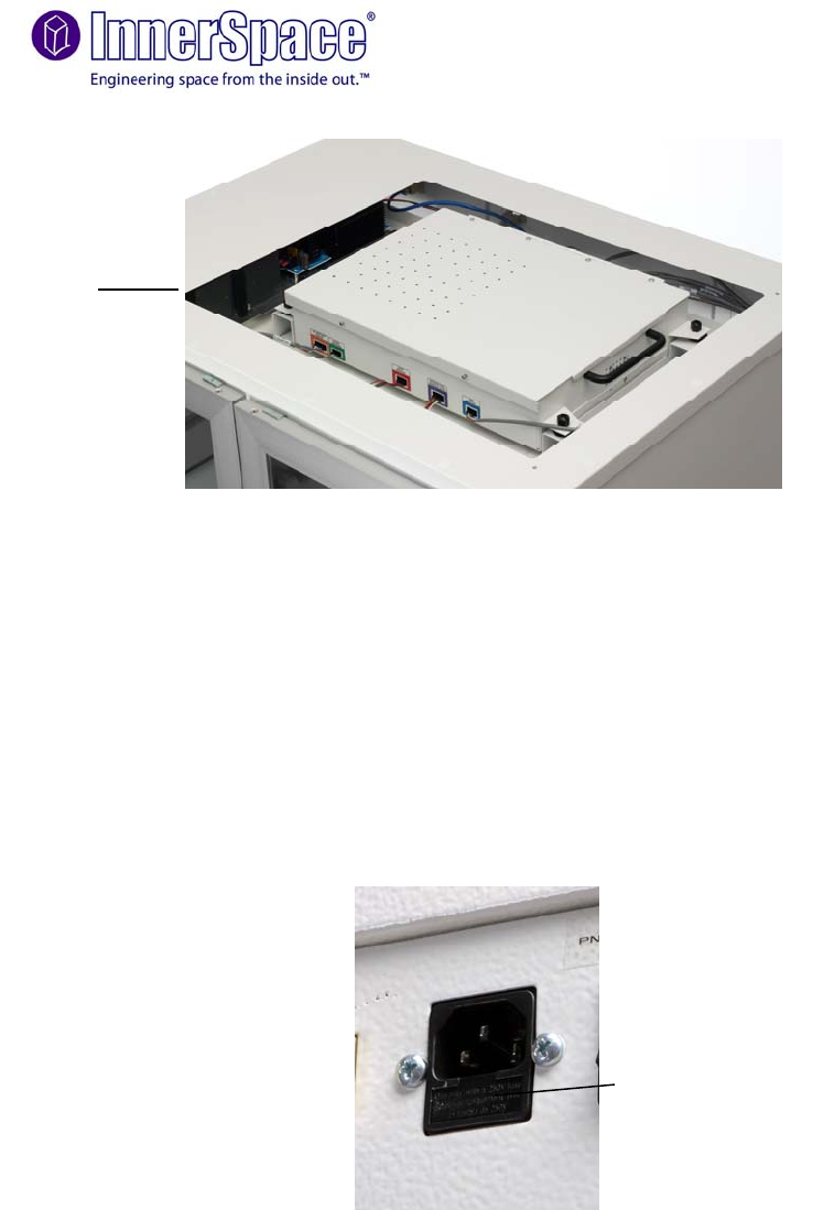
Power Supply Module
Back-Up Battery
Global Brain and
Interconnect
Lock Module
Thumbscrews
Top View of System 100 Cart

Service Hotline: 800.922.5966
System 100 User Guide Publication No. SYUG-1
11
6.3 RF-Enabled Shelves
Versatile within the cart.
Carts come standard with 10 shelves but are capable of accepting up to 16 shelves.
Each shelf has a RJ45 to connect to the back of the cart.
To reconfigure shelves, pull out and unhook the connection, place shelf in desired
location and reconnect. Each shelf is connected to the RJ45, 16 port jack on the upper
back of the cart using a shielded Cat 5E cable.

Service Hotline: 800.922.5966
System 100 User Guide Publication No. SYUG-1
12
7.0 spaceTRAX Information Engine
7.1 RFID Tags
System 100 RFID tags are small, adhesive backed tags that fit easily on the
outside package of most high-cost clinical supplies such as drug eluting stents,
ICDs, heart valves, orthopedic implants, implantable pain stimulators and etc.
System 100 utilizes a technology that requires passive high frequency RFID tags.
Passive tags do not require a power source or battery as they derive their energy
from the RFID reader.
Avoid contact with strong electromagnetic fields (MRI), do not crumple or tear
RFID tags.
7.2 Applying and Associating RFID Tags
Apply the RFID tags to the side of the item that will have direct contact with the
shelf.
There are two ways of associating items with RFID tags. The first is the most
common; when an item is added to the system and has the “RFID Required” box
checked, the normal ‘Add’ process will prompt for an RFID tag after the barcode
scan. Reading the RFID tag at that point will associate the unique .
The second way of associating items is after they have already been added.
Navigate to the item summary for the item and go into the current inventory tab,
then click on the ‘Details’ link. Click ‘Add New’ in the menu, fill in the details, and
then scan the new tag to associate it.
If at any time an RFID tag gets lost, broken, torn, or in any other way malfunctions
use the second method of adding an RFID tag to replace the missing and/or
malfunctioning tag.
7.3 Adding/Removing Tagged Items
Place the package so that the RFID tag is within 3 inches of the shelf. Make sure
not to block the ‘line of sight’ for the radio signal by covering the tag with metal, foil
or liquid barriers. This includes stacking items that use any of the aforementioned
barriers as packaging.
All items removed from the cart are tracked automatically by communication
between the RFID reader, antenna array and RFID tags.
No additional procedures are required when returning an unused tagged item to
the cart, the system will reconcile the inventory automatically. Make sure that
ALL items that are removed from the carts are either used or are replaced in
a timely fashion. Failure to do so will leave the system unable to reconcile
the missing items.
Assigning used (tagged) items to a patient or case is exactly the same as adding a
non-RFID item. The only thing to remain aware of is that for 100% accuracy in
your inventory it is important that RFID items be scanned out with an RFID
scanner and not a barcode scanner. While barcode scanners will work, the
uniqueness of the RFID tags makes them much more reliable in accurately
tracking inventory.
7.4 Available Reports
An RFID report called ‘RFID Summary’ will be available in the spaceTRAX
website that will track the cart contents, missing items, any unassociated items,
and general cart usage.

Service Hotline: 800.922.5966
System 100 User Guide Publication No. SYUG-1
13
7.5 Enrolling Authorized Users
Use the enrollment device to scan each cart user’s fingerprint once. After the scan
the fingerprint is transformed into a non-reconstitutable mathematical algorithm
that acts as the unique identifier for that person. The fingerprints are not stored
anywhere in the network, nor will they be broadcast anywhere to or from the carts.
The cart fingerprint readers match the print to the algorithm, not a map of the print
itself.
To capture the user’s fingerprint navigate to Settings Æ Organization Æ Users and
click on the triangle next to ‘Details’. Click ‘Fingerprints’, then ‘Add New’, when the
new dialog box opens, type a description for the print and then scan the user’s
print in using the enrollment device.
To add enrolled users to the carts, navigate to the RFID cart you wish to add to,
open it, and click on ‘Users’. A list of printed users will appear, simply follow the
process to add that user as an authorized user on the cart.
7.6 Deactivating Authorized Users
To remove enrolled users from the cart, navigate to the RFID cart you wish to
remove from, open it, and click on ‘Users’. A list of users associated with the cart
will appear, simply click on the triangle next to ‘Details’ and click ‘Delete’ to
remove the user.
8.0 Notes to the Customer
NOTE: Changes or modifications not expressly approved by the manufacture could
void the user's authority to operate the equipment.
NOTE: This equipment has been tested and found to comply with the limits for a
Class B digital device, pursuant to Part 15 of the FCC Rules. These limits are
designed to provide reasonable protection against harmful interference in a residential
installation. This equipment generates, uses and can radiate radio frequency energy
and, if not installed and used in accordance with the instructions, may cause harmful
interference to radio communications. However, there is no guarantee that
interference will not occur in a particular installation. If this equipment does cause
harmful interference to radio or television reception, which can be determined by
turning the equipment off and on, the user is encouraged to try to correct the
interference by one or more of the following measures:
-- Reorient or relocate the receiving antenna.
-- Increase the separation between the equipment and receiver.
-- Connect the equipment into an outlet on a circuit different from that to which the
receiver is connected.
-- Consult the dealer or an experienced radio/TV technician for help.
NOTE: The installer of this radio equipment must ensure that the antenna is located or
pointed such that it does not emit RF field in excess of Health Canada limits for the general
population; consult Safety Code 6, obtainable from Health Canada’s website www.hc-
sc.gc.ca/rpb
Service Hotline: 800.922.5966
System 100 User Guide Publication No. SYUG-1
14
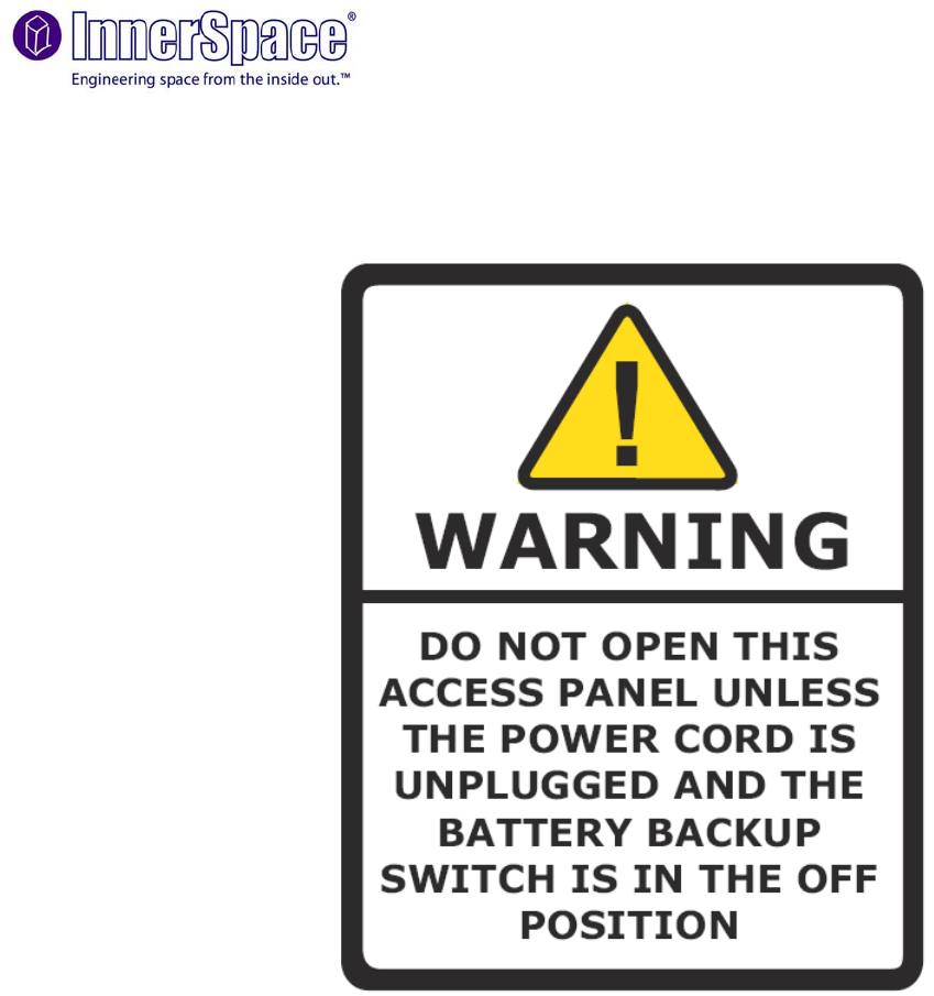
NOTE: Always disconnect AC power cord prior to removing access panel. Note that only
service personnel should have access to this area and this should not be performed by the
general public.