Star Micronics 150 Users Manual 100 7961g
150 to the manual 125dde58-5652-4c0b-b676-48e901827f18
2015-02-02
: Star-Micronics Star-Micronics-150-Users-Manual-487759 star-micronics-150-users-manual-487759 star-micronics pdf
Open the PDF directly: View PDF ![]() .
.
Page Count: 151 [warning: Documents this large are best viewed by clicking the View PDF Link!]
P OS
c
SERIES 150
Receipt/Validation/Journal Printers
PROGRAMMER'S
GUIDE
Rev G
PN: 100-7959
12/14/99

Programmer’s Guide PcOS Series 150 Change History
12/14/99 Rev G Page i
Change History
Rev. G
Added Telpar emulation
Added USB description
Added Redefine Character Set and Euro Character Commands
Updated Command Summary Tables
Rev. F
Removed redundant codes on page 82
Added Option 1: Epson emulation on page 90
Added Line Feed Before Cut to page 92
Added SSD Signal to page 96
Added Epson/Axiohm and STAR cash drawer connectors on page 118
Changed Code 3 of 9 to Code 39
Rev. E
Reformatted entire document
Corrected miscellaneous spelling and grammar mistakes
Changed RS1284 to IEEE 1284
Rev. D Update for Firmware Rev 1.20
Added NCR2567 emulation commands
Rev. C Update
Added section on parallel-port PnP
Added information about the web site
Added section on Star emulation
Removed all references to the cover (The Series 150 Printer does not have a switch on the cover.)
Added trademarks for OKIDATA and Star
Added Code 93 to bar code section
Added bar code justification commands
Rev. B Update
Corrected physical specifications
Corrected warranty information
Rev. A Initial Release

Disclaimer PcOS Series 150 Programmer’s Guide
Page ii Rev G 12/14/99
Disclaimer
Information in this publication is subject to change without notice. However, as product improvements
become available, Ithaca Peripherals will make every effort to provide updated information for the
products described in this publication.
Copyright
Copyright 1997-1999 Ithaca Peripherals. All rights reserved.
December 1999
Printed in the United States of America.
No part of this publication may be reproduced, stored in a retrieval system, or transmitted, in any form or
by any means, mechanical, photocopying, recording, or otherwise, without the prior written permission of
Ithaca Peripherals.
Trademarks
PcOS is a registered trademark of Ithaca Peripherals. Ithaca Peripherals is a Transact Technologies
Incorporated Company. IBM is a registered trademark of the International Business Machines
Corporation. Epson is a registered trademark of Seiko Epson Corporation. OKIDATA and Microline are
registered trademarks of OKI Electric Industry Co., Ltd. Star is a registered trademark of Star Micronics
Co., Ltd. Microsoft is a registered trademark of Microsoft Corporation. Windows, Windows NT, and Plug
and Play are trademarks of Microsoft Corporation.
Federal Communications Commission
Radio Frequency Interference Statement
The Series 150 Printe complies with the limits for a Class A computing device in accordance with the
specifications in Part 15 of FCC rules which are designed to minimize radio frequency interference during
installation; however, there is no guarantee that radio or television interference will not occur during a
particular installation. If this equipment does cause interference to radio or television reception, which can
be determined by turning the equipment off and on while the radio or television is on, the user is
encouraged to try to correct the interference by one or more of the following measures:
• Reorient the radio or television receiving antenna.
• Relocate the printer with respect to the receiver.
• Plug the printer and receiver into different outlets.
The user may need to consult their dealer or an experienced radio/television technician for additional
suggestions. The user may find the following booklet prepared by the Federal Communications
Commission helpful: How to Identify and Resolve Radio/TV Interference Problems.
The booklet is available from the United States Government Printing Office, Washington, DC 20402. Ask
for stock number 004-000-00345-4.

Programmer’s Guide PcOS Series 150 Table of Contents
12/14/99 Rev G Page iii
Table of Contents
Overview of the Series 150 Printer ............................................................................................................1
Warranty Information..................................................................................................................1
Warranty Options ..........................................................................................................1
Service Information .......................................................................................................1
What is in this book?...................................................................................................................1
Who should read this book? ...........................................................................................1
What does it cover?........................................................................................................1
Where can you find more information? ..........................................................................2
Contacting Ithaca Peripherals ........................................................................................2
General Description ..................................................................................................................................3
Series 150 Models .......................................................................................................................3
Standard Features........................................................................................................................3
Model 151: Receipt Printer..........................................................................................................4
Model 152: Receipt/Journal Printer .............................................................................................4
Model 153: Receipt/Journal/Validation Printer............................................................................4
Model 154: Receipt/Validation Printer.........................................................................................4
General Specifications...............................................................................................................................5
Printing Specifications.................................................................................................................5
Physical Specifications ................................................................................................................8
Dimensions....................................................................................................................8
Weight...........................................................................................................................8
Electrical Characteristics.............................................................................................................8
Self-powered AC............................................................................................................8
Interface Specifications..................................................................................................9
Media Specifications ...................................................................................................................9
Ribbon...........................................................................................................................9
Receipt Paper.................................................................................................................9
Receipt/Journal Paper ..................................................................................................10
Printable Area ...........................................................................................................................10
Receipt Printing...........................................................................................................10
Validation Forms Printing ...........................................................................................10
Validation - Top Insertion............................................................................................11
Validation - Left-side Insertion ....................................................................................11
Control Codes Overview .........................................................................................................................12
Nomenclature............................................................................................................................12
Standard Emulation.....................................................................................................13
IPCL Codes .................................................................................................................13
EPOS Emulation..........................................................................................................13
Microline Emulation....................................................................................................13
Star Emulation.............................................................................................................13
NCR2567 Emulation....................................................................................................14
Telpar Emulation.........................................................................................................14
Application Development ..........................................................................................................14
Tables and Charts......................................................................................................................14
Printer Control Codes..............................................................................................................................15
Print/Paper Motion....................................................................................................................15
Low-level Paper Motion Control..................................................................................15
Horizontal Motion Control...........................................................................................16
Vertical Motion Control ............................................................................................................18
Character Font...........................................................................................................................22

Table of Contents PcOS Series 150 Programmer's Guide
Page iv Rev G 12/14/99
International Character Sets and Code Pages.............................................................................24
Character Print Control .............................................................................................................30
Character Pitch..........................................................................................................................31
Character Attribute Commands .................................................................................................33
Print Rotation Commands .........................................................................................................40
Graphic Mode ...........................................................................................................................45
Standard APA Graphics...............................................................................................45
Bar codes...................................................................................................................................48
Validation Operation ...................................................................................................52
Validation Operation Control.......................................................................................53
Miscellaneous Control...............................................................................................................55
Printer Status Set/Inquire...........................................................................................................59
Parallel, Non-IEEE 1284 Mode Inquire .......................................................................59
Serial Mode Inquire.....................................................................................................60
Parallel, IEEE 1284 Mode Inquire ...............................................................................60
Dynamic Response Mode.............................................................................................60
Inquire Commands ......................................................................................................62
Extended Diagnostic Commands ...............................................................................................68
EPOS Codes..............................................................................................................................69
Real-time Status...........................................................................................................69
EPOS Command Summary..........................................................................................69
EPOS Deviations .........................................................................................................71
MICROLINE Codes ..................................................................................................................75
MICROLINE Command Summary ..............................................................................75
Star Codes.................................................................................................................................77
Star Command Summary.............................................................................................77
NCR2567 Codes........................................................................................................................79
NCR Command Summary ...........................................................................................79
Telpar Codes .............................................................................................................................80
Telpar Command Summary.........................................................................................80
Control Codes Summary by Code ..............................................................................................81
Control Codes Summary by Function.........................................................................................85
Operator Panel Controls..........................................................................................................................89
Push Buttons - Momentary Switches..........................................................................................89
Indicators ..................................................................................................................................89
Fault Indicators .........................................................................................................................90
Product Self-tests ....................................................................................................................................91
Level 0 Diagnostics ...................................................................................................................91
Extended Diagnostics ................................................................................................................91
Self test........................................................................................................................91
Hex-dump Mode .....................................................................................................................................92
Configuration Mode................................................................................................................................93
Initial Power ON .......................................................................................................................93
Manual Configuration ...............................................................................................................93
Enable Remote Configuration....................................................................................................93
Feature Configuration................................................................................................................94
General Control.........................................................................................................103
Vertical Control.........................................................................................................105
Character...................................................................................................................105
Interface ....................................................................................................................105
Options......................................................................................................................106
Save Changes ............................................................................................................106
Communications Protocol and Print Buffers..........................................................................................107
Overview.................................................................................................................................107

Programmer's Guide PcOS Series 150 Table of Contents
12/14/99 Rev G Page v
Parallel Port ............................................................................................................................110
Parallel Port Protocol.................................................................................................110
Printer Buffer Size.....................................................................................................111
Parallel Port Inquire IEEE 1284.................................................................................111
Parallel Port Inquire (Non-IEEE 1284) ......................................................................114
Parallel Port Plug and Play.........................................................................................115
Parallel Port Connector..............................................................................................116
Signal Levels .............................................................................................................116
Serial Port ...............................................................................................................................117
Serial Port Features....................................................................................................117
Serial Port Pin-out .....................................................................................................117
Serial Port Protocol....................................................................................................118
Print Buffer Flow.......................................................................................................120
Printer Buffer Size.....................................................................................................123
Serial Port Inquire .....................................................................................................124
Remote Printer Reset...............................................................................................................125
Reset in Serial Mode..................................................................................................125
Reset in Parallel Mode...............................................................................................125
Power-cycle Recovery..............................................................................................................125
Programmer’s Notes................................................................................................................126
Cash Drawer Interface...........................................................................................................................127
Interface Description ...............................................................................................................127
Interface Connectors................................................................................................................127
Printing Graphics..................................................................................................................................128
Character Graphics..................................................................................................................128
APA Graphics .........................................................................................................................130
Appendix A Language Tables ...............................................................................................................133
Appendix B ASCII Code Chart .............................................................................................................135
Appendix C Ordering Cables ................................................................................................................136
General Information................................................................................................................136
Index.....................................................................................................................................................137

Figures and Tables PcOS Series 150 Programmer's Guide
Page vi Rev G 12/14/99
Table of Figures
Figure 1 Single-wide character cell ...........................................................................................................7
Figure 2 Character forming.......................................................................................................................7
Figure 3 Physical dimensions....................................................................................................................8
Figure 4 Receipt printable area................................................................................................................10
Figure 5 Validation print – top insertion .................................................................................................11
Figure 6 Validation print – left-side insertion..........................................................................................11
Figure 7 Example of fine line feed...........................................................................................................18
Figure 8 Data sent to printer for fine line feed.........................................................................................18
Figure 9 Examples of character print.......................................................................................................31
Figure 10 Example of one-line double-wide print....................................................................................33
Figure 11 Data sent to printer for one-line double-wide print...................................................................33
Figure 12 Example of underline, enhanced, emphasized, superscript, and subscript print........................39
Figure 13 Paper-error to inquire-request timing.......................................................................................60
Figure 14 Parallel link options ..............................................................................................................105
Figure 15 Typical POS system...............................................................................................................107
Figure 16 Host to printer link................................................................................................................107
Figure 17 Printer communications buffer flow.......................................................................................108
Figure 18 Parallel port data timing........................................................................................................110
Figure 19 PE to ENQ request timing.....................................................................................................114
Figure 20 Serial port flow control using DTR........................................................................................118
Figure 21 Serial port flow control XON/XOFF......................................................................................119
Figure 22 Serial buffer operation...........................................................................................................120
Figure 23 Print controller using data.....................................................................................................122
Figure 24 Inquire flow...........................................................................................................................124
Figure 25 Receipt with extended graphic characters ..............................................................................129
Figure 26 Receipt with APA graphics....................................................................................................130
Table of Tables
Table 1 Normal print zone character specifications ...................................................................................5
Table 2 Wide print zone character specifications.......................................................................................6
Table 3 Power input requirements.............................................................................................................8
Table 4 Validation lines ..........................................................................................................................10
Table 5 Language table IDs.....................................................................................................................25
Table 6 EPOS language table IDs............................................................................................................25
Table 7 Code page definition table ..........................................................................................................26
Table 8 EPOS code page definition table.................................................................................................27
Table 9 Euro Character Substitution Matrix ............................................................................................29
Table 10 Print modes ..............................................................................................................................30
Table 11 Intercharacter spacing table ......................................................................................................32
Table 12 Rotated print spacing................................................................................................................40
Table 13 Parallel port pin-outs ..............................................................................................................116
Table 14 Serial bit rates.........................................................................................................................117
Table 15 Serial port pin-outs.................................................................................................................117
Table 16 Ithaca cash drawer connector..................................................................................................127
Table 17 Epson/Axiohm cash drawer connector ....................................................................................127
Table 18 Star cash drawer connector.....................................................................................................127
Table 19 Code page definitions .............................................................................................................134

Programmer's Guide PcOS Series 150 Table of Figures
12/14/99 Rev G Page vii
Table 20 ASCII chart............................................................................................................................135

Programmer's Guide PcOS Series 150 Overview
12/14/99 Rev G Page 1
Chapter 1:
Overview of the Series 150 Printer
Warranty Information
Warranty Options
All PcOS Series 150 Printers come with a standard 24-month warranty covering both parts and
labor. An optional warranty, covering both parts and labor for an additional 12 months, may be
purchased separately. For more information concerning the warranty options, please contact your
dealer or the Sales Department at Ithaca Peripherals. See “Contacting Ithaca Peripherals” on
page 2.
Service Information
Ithaca Peripherals has a full service organization to meet your printer service and repair
requirements.
If your printer needs service, please directly contact Ithaca Peripherals’ Technical Support
Department at (607) 257-8901 for a return authorization.
Ithaca Peripherals offers the following service programs to meet your needs:
• Extended Warranty
• Depot Repair
• Maintenance Contract
What is in this book?
Who should read this book?
This book is intended for system engineers or system integrators. It contains the information
needed to integrate the Series 150 Printer with a point-of-sale terminal and to program the
terminal to communicate with the printer.
What does it cover?
This guide provides the following information:
• Start-up information including diagnostics and fault conditions,
• Command descriptions,
• Character fonts,
• Printer features,
• Parallel and RS-232 interface information,
• Communications and buffers, and
• Command code reference tables.

Overview PcOS Series 150 Programmer's Guide
Page 2Rev G12/14/99
Where can you find more information?
An Operator's Guide is available that describes set up and use of the Series 150 Printer. It
describes basic procedures such as changing the paper; printing on a form; and replacing the
ribbon cassette. A Maintenance Manual is also available. It shows how to repair the Series 150
Printer and lists the replacement parts. The Maintenance Manual is intended for trained, service
technicians. For information about ordering these books or programs, refer to the next section.
In addition, there are a number of drivers available that will support various environments.
CFG 90/150 User’s Guide PN 100-01085
Windows 95 print driver with documentation PN 100-9167
Windows NT 4.0 print driver with documentation PN 100-9170
OPOS drivers with documentation PN 100-9732
Master character set definitions PN 100-9785
Contacting Ithaca Peripherals
The Sales and Technical Support Departments will be able to help you with most of your
questions. Contact the Sales Department to order documentation, receive additional information
about the Series 150 Printer, order supplies, or obtain information about other products by Ithaca
Peripherals. Contact the Technical Support Department for information about your warranty, to
send a printer in for service, or for technical support.
You may reach both the Sales and Technical Support Departments at the following address and
phone or fax numbers.
Ithaca Peripherals
20 Bomax Drive
Ithaca, NY 14850
Main phone (607) 257-8901
Main fax (607) 257-8922
Sales fax (607) 257-3868
Technical Support fax (607) 257-3911
Technical Support E-mail techsupport@ithper.com
Internet Support
Ithaca Peripherals maintains an Internet web site. The address is http://www.ithper.com. On
the technical support page, you will find support information on all of our printers. The
Series 150 Printer support pages offer the latest information. They include the current
version of this manual, program examples, test procedures, programming instructions, and
supported print drivers.

Programmer's Guide PcOS Series 150 General Description
12/14/99 Rev G Page 3
Chapter 2:
General Description
Series 150 Models
There are four basic models of the Series 150 Printer. They are:
Model 151 Receipt Printer;
Model 152 Receipt/Journal Printer;
Model 153 Receipt/Journal/Validation Printer; and
Model 154 Receipt/Validation Printer.
Standard Features
The following features are common to the entire family of printers:
• 340 cps logic-seeking print speed;
• 4.0 inches per second paper feed speed;
• 2.40-inch (normal) or 2.83-inch (wide) print zone;
• Snap on ribbon cassette;
• Dual cash drawer drivers with status;
• Centronics parallel, IEEE 1284, serial RS-232C, or USB interfaces;
• Configurable receive buffer;
• Standard, Epson, Microline, Star, NCR2567, and Telpar emulations;1
• Standard all-points-addressable (APA) or EPOS bit-image graphics;
• Standard and EPOS International Character Sets;
• 8, 10, 12, 15, 17.1, 20, and 24 characters per inch selections;
• Emphasized, enhanced, double-wide, double-high, double-wide double-high, half-high,
underline, subscript, superscript, and rotated print;
• Operator-visible print zone;
• Self-diagnostics; and
• Setup and configuration utility program.
1 Other emulation’s can be made available. Contact Ithaca Peripherals’ Sales Department for more
information. See “Contacting Ithaca Peripherals” on page 2.

General Description PcOS Series 150 Programmer's Guide
Page 4Rev G12/14/99
Model 151: Receipt Printer
The Model 151 receipt printer only provides receipt functions. The last line printed on the receipt is
within one inch of the tear-off or cut-off edge. The receipt printing appears right-side up with the
total at the bottom as the receipt appears from the top of the printer and is presented to the operator.
The receipt printer handles one-, two-, or three-ply paper. The optional cutter is able to cut one- and
two-ply paper.
The Model 151 printer does not have the ability to validate. Commands that operate validation modes
on other Series 150 Printers will not function.
Model 152: Receipt/Journal Printer
The Model 152 receipt/journal printer adds the journal feature to the Model 151 receipt printer. The
journal take-up is able to rewind the second copy of the 3.5-inch diameter 2-ply paper roll (125 feet).
The Model 152 printer does not have the ability to validate. Commands that operate validation modes
on other Series 150 Printers will not function.
Model 153: Receipt/Journal/Validation Printer
The Model 153 receipt/journal/validation printer adds a validation capability to the Model 152. The
validation will accommodate up to 16 lines at 8.0 lines per inch (lpi) or 12 lines at 6.0 lpi.
The form is inserted from the front and extends out the left side and/or top of the printer. It rests on a
fixed form stop. The validation movement is controlled from the movement of the receipt and journal.
Model 154: Receipt/Validation Printer
The Model 154 receipt/validation printer adds validation, as described above, to the Model 151. This
is a Model 153 without journal take-up.
Programmer's Guide PcOS Series 150 General Specifications
12/14/99 Rev G Page 5
Chapter 3:
General Specifications
Printing Specifications
Printing method impact dot matrix
Head wire arrangement 9 pins in line
Print wire diameter 0.34 mm (0.012 inch)
Print wire pitch 0.35 mm (0.013 inch)
Printing directions bidirectional, logic-seeking
Print zone 60.96 mm (2.40 inch) or 71.97 mm (2.83 inch)
Characters per inch Refer to Table 1.
Characters per line Refer to Table 1.
Characters per second Refer to Table 1.
Print Pitch Capability
(in characters per inch) Normal 2.40” Maximum
Characters per Line Characters per
Second
8 18 220
10 24 275
12 28 330
15 36 340
17.1 (condensed) 41 340
20 (super-condensed) 48 340
24 (super-condensed) 57 340
5 (double-wide) 12 175
6 (double-wide) 14 175
7.5 (condensed, double-wide) 18 175
8.5 (condensed, double-wide) 20 175
10 (super-condensed, double-wide) 24 175
12 (super-condensed, double-wide) 28 175
Table 1 Normal print zone character specifications
Note: The Series 150 Compatibility Mode can be set in menu RAM and will limit printing to 40
characters in 17.1 characters per inch (cpi).

General Specifications PcOS Series 150 Programmer's Guide
Page 6Rev G12/14/99
Print Pitch Capability
(in characters per inch)
Wide 2.83” Maximum
Characters per Line
Characters per
Second
8 22 (180)
10 28 (250)
12 34 (275)
15 42 (275)
17.1 (condensed) 48 (275)
20 (super-condensed) 56 (275)
24 (super-condensed) 68 (275)
5 (double-wide) 14 (140)
6 (double-wide) 17 (140)
7.5 (condensed, double-wide) 21 (140)
8.5 (condensed, double-wide) 24 (140)
10 (super-condensed, double-wide) 28 (140)
12 (super-condensed, double-wide) 34 (140)
Table 2 Wide print zone character specifications
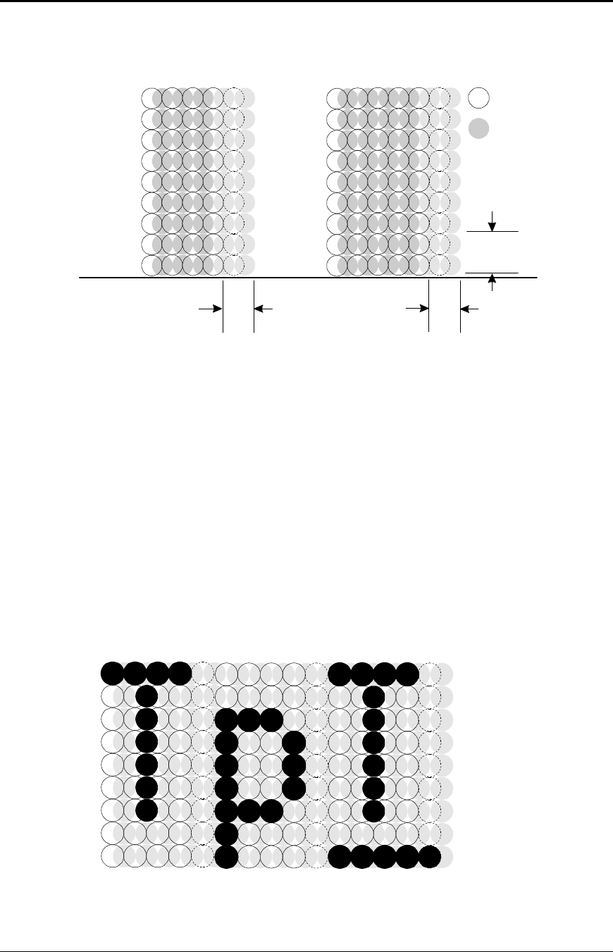
Character Generation
All the character sets and modes are based on one of two character cells, 10 wide by 9 high
or 12 wide by 9 high. Double-wide mode is twice the width of normal mode, 20 wide by 9
high or 24 wide by 9 high.
In utility print mode, the character cell consists of five full dots and five half dots
horizontally by nine full dots vertically. The character cell is 9 by 9. In high speed draft
(HSD) mode, the character cell is shortened by one half and one full dot column yielding a 7
by 9 character.
Each character is justified to the left of the cell. The first four columns of the full dots and
the first three columns of the half dots are used to generate the character in high speed draft.
In utility mode, the first five columns of the full dots and the first four columns of the half
dots are used. The last full dot and the last two half dots are used for character spacing in
both modes.
Programmer's Guide PcOS Series 150 General Specifications
12/14/99 Rev G Page 7
The following illustration shows a single-wide character cell.
1 3 5 7 9 11
2 4 6 8 10 12
Full Dots
Half Dots
Descender (Row 8 & 9)
& Underline (Row 9)
Character
Spacing
1
2
3
4
5
6
7
8
9
1 3 5 7 9
2 4 6 8 10
Character
Spacing
1
2
3
4
5
6
7
8
9
High Speed Draft Utility Mode
Figure 1 Single-wide character cell
The example above, which only holds true for the 12 cpi mode, shows the full dots as
adjacent to each other in the character cell. The 10 cpi mode allows a gap between adjacent
full rows; 17 and 24 cpi allow an overlap of full rows. The printer cannot print adjacent full
and half dots in any single row. Some graphics (double-density, half-speed) allow adjacent
rows to be printed by slowing the print speed by half. Slowing the print speed allows the time
between half and full columns to be the same as the time between full columns in full-speed
operation.
The following illustration shows the use of full and half dots as well as descenders to form
characters.
1 3 5 7 9
2 4 6 8 10
1 3 5 7 9
2 4 6 8 10
1 3 5 7 9
2 4 6 8 10
1
2
3
4
5
6
7
8
9
Figure 2 Character forming
General Specifications PcOS Series 150 Programmer's Guide
Page 8Rev G12/14/99
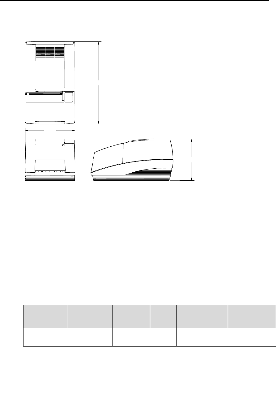
Physical Specifications
Dimensions
11.25 inches (286 mm)
6.63 inches
(168 mm)
5.75 inches (146 mm)
Figure 3 Physical dimensions
Weight
Approximate weight 7.0 pounds (3.2 kg)
Shipping weight 10.0 pounds (4.5 kg)
Electrical Characteristics
Self-powered AC
The Series 150 Printer is designed to be AC self-powered in domestic and international markets.
The printer is equipped with a universal input power supply that is designed to operate
worldwide without modification.
Supply
Voltage
Rating (VAC)
Supply
Voltage
Range (VAC)
Frequency
(Hz) Rated
Power
(watts)
Idle Current
(amps) Printing
Current (amps)
100 - 240 90 - 264 47 - 63 45 0.08 @ 120VAC
0.04 @ 240VAC
0.9 @ 120VAC
0.4 @ 240VAC
Table 3 Power input requirements

Programmer's Guide PcOS Series 150 General Specifications
12/14/99 Rev G Page 9
Interface Specifications
Serial
The serial interface is a standard RS-232 interface on a 9-pin D-shell connector. It is defined
as a standard DTE device. A null modem cable is required to interface the printer to another
DTE device (i.e. a personal computer). See the serial port description later in this manual for
more information.
Parallel
The parallel port is a standard 25-pin D-shell as defined in the IEEE 1284-A standard. See
the parallel port description later in this manual for more information.
USB
The USB interface is a standard Series “B” receptacle as defined in the USB standard. The
printer is a self-powered device and does not draw power over the cable.
Cash Drawer
The Series 150 Printer supports dual cash drawers with status. The interface will provide
status and 24 VDC at up to 1.5 amps to the cash drawer. See the cash drawer interface
description later in this manual.
Media Specifications
Ribbon
Inking method Cartridge type, 1.8 m seamless ribbon with reinker
Ink color Black or purple
Ribbon life at 25 °C3 million (black) or 4.5 million (purple) characters to ink depletion2
Manufacturer Only Ithaca Peripherals approved ribbons should be used.
Receipt Paper
Paper feed method Friction feed
Paper feed pitch Default - 0.13 inch (1/8 inch or 3.18 mm); can be set in units of
0.0046 inch (1/216 inch or 0.12 mm) by software command
Paper width 2.75, 3.00, or 3.25 inches (69.85, 76.20, 82.55 mm)
Roll diameter 3.50 inches (88.90 mm)
Paper thickness 0.003 - 0.0035 inch (0.76 - 0.089 mm) at 25 °C
Roll paper core Inside diameter 0.44 inch (7/16 inch or 11.11 mm)
Roll footage (typical) 240 feet (7315 cm)
Receipt-paper out Paper exhaust is sensed by software, and printing is prevented at the
end of the roll.
2 The ribbon must be from an approved manufacturer and tested with a rolling ASCII test pattern using 15
characters per inch (cpi) in high speed draft (HSD) mode.
General Specifications PcOS Series 150 Programmer's Guide
Page 10 Rev G12/14/99
Receipt/Journal Paper
Paper-feed method Friction feed
Paper-feed pitch Default - 0.13 inch (1/8 inch or 3.18 mm); can be set in units of
0.0046 inch (1/216 inch or 0.12 mm) by software command
Paper width 2.75, 3.00, or 3.25 inches (69.85, 76.20, 82.55 mm)
Roll diameter 3.50 inches (88.90 mm)
Paper thickness at 25 °C
Two-ply 0.006 - 0.007 inch (0.15 - 0.18 mm)
Three-ply 0.009 - 0.0105 inch (0.23 - 0.27 mm)
Roll paper core Inside diameter 0.44 inch (7/16 inch or 11.11 mm)
Roll footage (typical)
Two-ply 110 feet (3353 cm)
Three-ply 70 feet (2134 cm)
Receipt-paper out Paper exhaust is sensed by software, and printing is prevented at the
end of the roll.
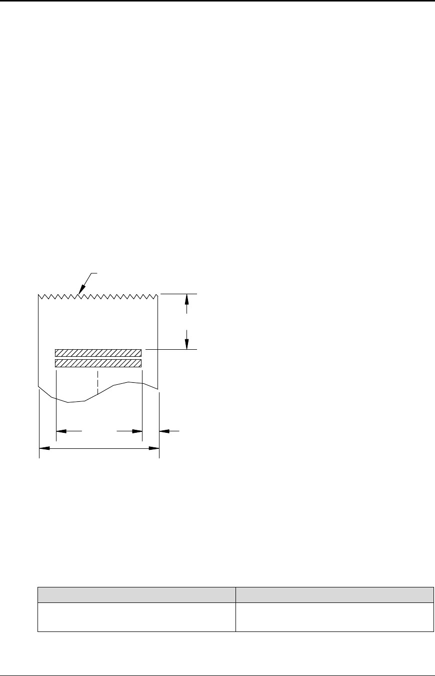
Printable Area
Receipt Printing
1.00 inch (25.4 mm)
0.46 inch (11.68 mm)
2.34 inches
(59.44 mm)
3.25 inches
(82.55 mm)
Paper tear-off
Figure 4 Receipt printable area
Receipt Printing with the Autocutter
The paper is cut one inch from the last line of print, which minimizes the wasted paper
required when the paper must be moved to the cut-off position.
Validation Forms Printing
Lines per inch (lpi) Lines
8 16
6 12
Table 4 Validation lines
Programmer's Guide PcOS Series 150 General Specifications
12/14/99 Rev G Page 11
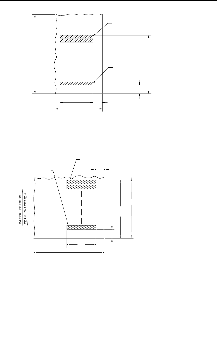
Validation - Top Insertion
First line of print
Last line of print
2.85 inches (72.39 mm)
0.68 inch (17.15 mm)
2.34 inches
(59.44 mm)
2.50 inches (min) (63.50 mm)
0.50 in
(12.70 mm)
4.25 inches (min)
(107.95 mm)
Figure 5 Validation print – top insertion
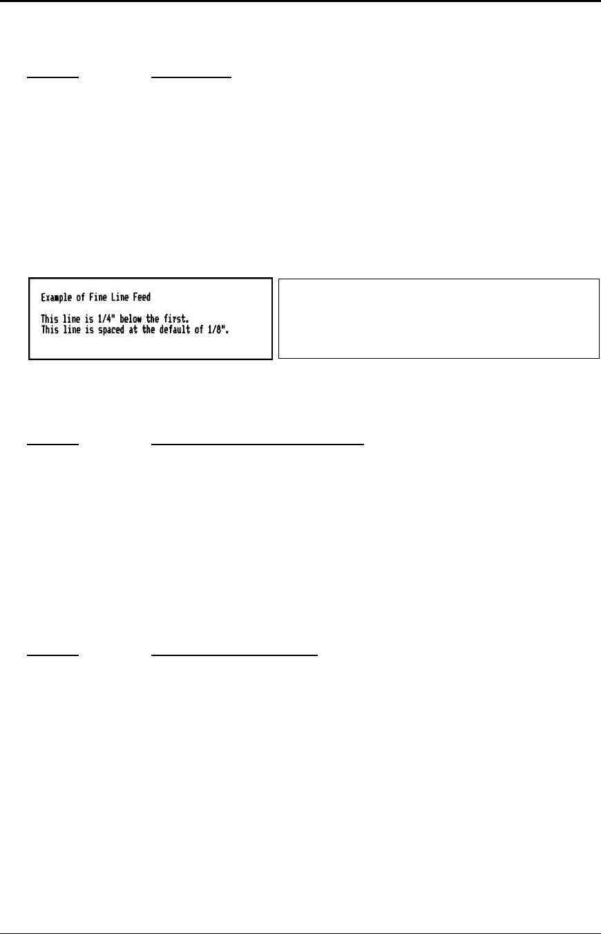
Validation - Left-side Insertion
Figure 6 Validation print – left-side insertion
Validation Forms Insertion
Form insertion is from the top or the left side of the printer. Automatic form location is
under software or firmware control. Character rotation under software control will allow
check validation to appear right-side up when the check is removed.
2.50 inches (min) (63.50 mm)
Last line of print
First line of print
0.50 inch
(12.7 mm)
2.85 inches
(72.39 mm)
6.00 inches (min) (152.40 mm)
2.34 inches
(59.44 mm)
0.68 inch (17.15 mm)

Control Codes Overview PcOS Series 150 Programmer's Guide
Page 12 Rev G12/14/99
Chapter 4:
Control Codes Overview
This programmer’s guide is designed to help users of the PcOS Series 150 Printer develop applications.
The Series 150 Printer is a point-of-sale (POS) printer that has several features not normally found on
general purpose printers. Because of these special features, the Series 150 Printer has distinct control
codes. This manual documents the control codes with an emphasis on those codes that are unique to the
Series 150 Printer.
All PcOS Series 150 Printers have either a serial or parallel interface. Both interfaces provide the same
printer control3 and use the same codes.
Nomenclature
When describing control codes, there is often confusion as to whether the description is decimal,
hexadecimal, or ASCII. To minimize the confusion, this manual will use the following nomenclature
when describing control code sequences.
[ ] encloses a control character. This is a single, 8-bit value as defined in the standard
ASCII tables. An example would be [ESC], which would represent a 1BH or 27
decimal.
< > encloses an 8-bit value in decimal format. This value will be from 0 to 255. An
example would be <2>, which would represent 02H or 2 decimal.
<n> indicates a variable parameter. <n> can have a value of from 0 to 255. The meaning
of <n> is described and defined in the description of the command.
<n1> <n2>indicates that there are two parameters, <n1> and <n2>, where both can have values
from 0 to 255.
<m1> <m2>is an IPCL parameter consisting of two digits where <m1> and <m2> are ASCII
characters from 0 to 9. The values will be combined to form a value from 0 to 99. If
<m3> is included, the parameter will be combined to form a value from 0 to 999.
If two values are specified, there must be two bytes added to the IPCL code. In other
words, if the command specifies <m1> <m2> and the desired value is 5, the value
must be specified as 05.
x(all other characters in control strings) represent ASCII characters. For example,
[ESC] 1 would represent 1BH followed by 31H.
The CFG150 configuration and demonstration program4 uses the same nomenclature. Print examples
shown in this manual are available for CFG150.
3 The serial and IEEE 1284 interfaces provide a few additional interface capabilities over the standard
parallel interface. Both serial and IEEE 1284 interfaces provide a bidirectional data path.
4 CFG150 is available from Ithaca Peripherals. The program runs on IBM personal computers and
compatibles.

Programmer's Guide PcOS Series 150 Control Codes Overview
12/14/99 Rev G Page 13
In many cases, applications require that control sequences be specified in hexadecimal or decimal
codes. In most cases, commands are specified in ASCII, hexadecimal, and decimal. The table in
Appendix B lists ASCII, decimal, and hexadecimal equivalents.
Standard Emulation
The standard control codes for the Series 150 Printer are extensions and subsets of the IBM
emulation provided on other PcOS products. In all cases, an application designed for a Series 50
Printer with IBM code sets will function with a Series 150 printer. There are, however, more
features in the Series 150 Printer that can be used for new applications.
IPCL Codes
IPCL (Ithaca Printer Control Language) codes are designed to control a printer without using
control characters, i.e., characters less than 20H. Only the standard emulation supports IPCL.
Not all commands are supported by IPCL codes. For those commands that are, the IPCL code is
listed.
In rare cases, an IPCL code will interfere with the text that is to be printed. The IPCL translator
can be disabled with an [ESC] y <4> command.
EPOS Emulation
ESC/POS5 is referred to here as EPOS. The Series 150 Printer supports an EPOS emulation with
extensions. The emulation is designed to allow the Series 150 Printer to be used with applications
that are designed for Seiko Epson printers. It is intended that the standard emulation be used for
new applications. Not all of the features of Series 150 Printers are supported by EPOS.
This manual will include the EPOS code equivalent for features of the Series 150 Printer that are
supported by EPOS. When EPOS commands are significantly different from the standard
emulation, an independent EPOS description is provided.
Microline Emulation
The standard control codes for the Series 150 Printer are extensions and subsets of the Microline
emulation provided on other PcOS products. In all cases, an application designed for a Series 50
Printer with Microline 150 Printer that can be used for new applications.
Star Emulation
The standard control codes for the Series 150 Printer are extensions and subsets of the Star
emulation provided on other PcOS products. In all cases, an application designed for a Series 50
Printer with Star code sets will function with a Series 150 Printer. There are, however, more
features in the Series 150 Printer that can be used for new applications.
5 ESC/POS is a registered trademark of the Seiko Epson Corporation.

Control Codes Overview PcOS Series 150 Programmer's Guide
Page 14 Rev G12/14/99
NCR2567 Emulation
The standard control codes for the Series 150 Printer are extensions and subsets of the NCR2567
emulation provided on other PcOS products. In all cases, an application designed for a Series 50
Printer with NCR2567 code sets will function with a Series 150 Printer. There are, however,
more features in the Series 150 Printer that can be used for new applications.
Telpar Emulation
The standard control codes for the Series 150 Printer are extensions and subsets of the Telpar
emulation provided on other PcOS products. In all cases, an application designed for a Series 50
Printer with Telpar code sets will function with a Series 150 Printer. There are, however, more
features in the Series 150 Printer that can be used for new applications.
Application Development
To aid in application development and help the programmer understand the Series 150 Printer, this
manual is broken down into two major sections. The first section is a detailed description of each of
the commands. The second section is an explanation of how the printer works. It explains the internal
print buffer, the communications link, and how the host computer and printer interact.
Tables and Charts
Throughout this guide, there are charts and tables that list commands and features. In most cases, the
charts cross reference the page that describes the command. Commands are grouped by function and
can at times be hard to find. To minimize the time it takes to find commands, there are two code
summary charts in the following section, one ordered by code and one by function.

Programmer's Guide PcOS Series 150 Control Codes
Print/Paper Motion
12/14/99 Rev G Page 15
Chaper 5:
Printer Control Codes
Print/Paper Motion
Low-level Paper Motion Control
Function Carriage return
ASCII [CR]
Hexadecimal 0DH
Decimal <13>
IPCL &%CR
EPOS 0DH
Description This command prints the contents of the print buffer (if any) and resets the
next character print position to the left margin. A line feed is not
performed unless autofeed was active. The left margin is defined by the
current print station, the print rotation direction, and the left margin
command.
Note: In single-line mode, the [CR] is used to terminate all lines. The
printer will go busy6 after the [CR] is received. The printer will not be
ready to accept data again until the previous data has printed.
Function Line feed
ASCII [LF]
Hexadecimal 0AH
Decimal <10>
IPCL &%LF
EPOS 0AH
Description This command prints the contents of the buffer (if any) and advances the
paper one line at the current default line spacing. The next character print
position is not reset to the left margin unless auto-CR is active.
6 In one-line mode, the parallel port busy signal will occur as a result of receiving the [CR].
In serial mode, the busy indication will be delayed until the [CR] is processed by the input software.
Data sent to the printer after the [CR] will not be lost unless the printer is power cycled.

Control Codes PcOS Series 150 Programmer's Guide
Horizontal Motion
Page 16 Rev G12/14/99
Horizontal Motion Control
There are several commands that can control the horizontal position of characters. Many
applications use space control to position fields. However, there is the ability to control character
position with horizontal tab stops. This is done by using the horizontal tab [HT] to move to those
tab stops.
Function Horizontal tab
ASCII [HT]
Hexadecimal 09H
Decimal <9>
IPCL &%HT
EPOS [HT]
Description This command inserts spaces in the print buffer up to the next tab stop.
The default tab locations are every 8 spaces.
Function Back space
ASCII [BS]
Hexadecimal 08H
Decimal <8>
IPCL &%BS
EPOS [BS]
Description This command prints the data in the print buffer and shifts the current
horizontal position by one character width to the left. If the current
position is at the left margin, the [BS] is ignored.
Function Set horizontal tab stops
ASCII [ESC] D <n1> <n2> <n3> ... <ni> 0
Hexadecimal 1BH 44H <n1> <n2> <n3> ... <ni> 00H
Decimal <27> <68> <n1> <n2> <n3> ... <ni> <0>
IPCL none
EPOS [ESC] D <n1> <n2> <n3> ... <ni> 0
Description This command sets tab stops at the character columns specified by <n>.
The end of the setting is specified by a <0>. All previously set tabs will be
cleared by this command. There is no restore-defaults procedure other than
to respecify the tabs. The power up default is every 8 spaces, i.e., 9, 17, 25,
etc. Column sizes are in accordance with the current character pitch.
Setting tabs that are beyond the station width is possible. A [CR] will be
inserted if the tab is used. Printing will begin at the home position.

Programmer's Guide PcOS Series 150 Control Codes
Horizontal Motion
12/14/99 Rev G Page 17
Function Reset horizontal and vertical tab stops
ASCII [ESC] R
Hexadecimal 1BH 52H
Decimal <27> <82>
IPCL &%HV
EPOS none
Description This command resets horizontal and vertical tab stops to power up
configuration. The power up horizontal default is every 8 spaces, i.e., 9,
17, 25, etc. The vertical default is every line.
Function Set justification
ASCII [ESC] a <n>
Hexadecimal 1BH 61H <n>
Decimal <27> <97> <n>
IPCL &%JL, &%JC, &%JR
EPOS [ESC] a <n>
Description This command sets the horizontal justification.
Where <n> 0 = left justified &%JL
1 = center justified &%JC
2 = right justified &%JR
The print format can be right, center, or left justified. The value of <n>
specifies the justification.
The power on default is left justified.
Note: Lines that have mixed size characters cannot be centered. For
example, a line with mixed single- and double-high cannot be centered. If
a line of print is to be double-high and centered, the change to single-high
must be done after the line terminator for the double-high line.
Example: [ESC] W <3> Centered [ESC] W <0> [CR] will not print
correctly because the printer assumes that more data will follow the [ESC]
W <0>. This should be [ESC] W <3> Centered [CR] [ESC] W <0>.
Note: Several line graphic characters stress the printer. If the printer is to
print a very dark area, it will do it in steps. The stepping operation only
works in left justified mode. In general, this will not cause a problem
because the printer will print several black blocks in a row before the
stepping program is activated. Autocenter and line graphics should be
avoided because of character alignment.
Note: Justify commands do not affect graphics.
Control Codes PcOS Series 150 Programmer's Guide
Vertical Motion
Page 18 Rev G12/14/99
Vertical Motion Control
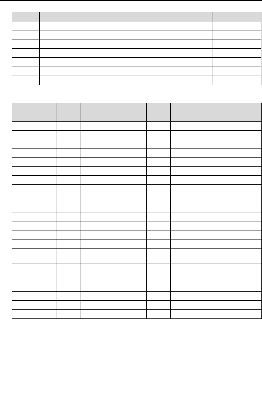
Function Fine line feed
ASCII [ESC] J <n>
Hexadecimal 1BH 4AH <n>
Decimal <27> <74> <n>
IPCL &%FM <m1> <m2> <m3>
EPOS [ESC] J <n>
Description This command prints the contents of the buffer (if any) and performs a line feed
of n/216 inch. This command does not change the default line spacing value.
The next character print position is reset to the left margin.
EPOS Note: In EPOS mode, this command performs line feeds in n/144-inch
increments.
Figure 8 Data sent to printer for fine line feed
Function Set variable line space in n/216 inch
ASCII [ESC] 3 <n>
Hexadecimal 1BH 33H <n>
Decimal <27> <51> <n>
IPCL &%SV <m1> <m2> <m3>
EPOS [ESC] 3 <n>
Description This command sets the default line spacing in n/216 inch. Set n = 1 to 255.
This command takes effect immediately and sets the line feed spacing used by
[LF] to values other than 1/8 or 7/72 inch.
EPOS Note: Line spacing of n/144 is used.
Function Set line space to 27/216 inch
ASCII [ESC] 0
Hexadecimal 1BH 30H
Decimal <27> <48>
IPCL &%ST
EPOS [ESC] 2
Description This command sets the text default line spacing to 1/8 or 27/216 inch which is
the standard eight lines per inch line spacing at initial power up.
EPOS Note: In EPOS mode, this command sets 1/6-inch spacing or 6 lines per
inch.
Example of Fine Line Feed[CR]
[ESC]J<54>
This line is 1/4" below the first.[CR][LF]
This line is spaced at the default of
1/8".[CR][LF]
Figure 7 Example of fine line feed

Programmer's Guide PcOS Series 150 Control Codes
Vertical Motion
12/14/99 Rev G Page 19
Function Set line space 21/216 or 7/72 inch
ASCII [ESC] 1
Hexadecimal 1BH 31H
Decimal <27> <49>
IPCL &%SG
EPOS none
Description This command sets the default line spacing to 21/216 inch. This line spacing is
for all-points-addressable (APA) graphics printing.
Function Set variable line space n/72 inch
ASCII [ESC] A <n>
Hexadecimal 1BH 41H <n>
Decimal <27> <65> <n>
IPCL none
EPOS none
Description This command sets default line spacing to n/72. Set n = 1 to 85. This line
spacing does not take effect until enabled by the [ESC] 2 command. This
command is provided to maintain backward compatibility with the Series 50,
OKIDATA, IBM, and other printers. It can also be used to print on preprinted
forms.
Function Enable [ESC] A <n> line spacing
ASCII [ESC] 2
Hexadecimal 1BH 32H
Decimal <27> <50>
IPCL none
EPOS none
Description [ESC] 2 enables [ESC] A <n> line spacing. This is a companion to the [ESC]
A <n> command and puts the specified line spacing into effect. It will remain
in effect until another line spacing command is issued.
Function Feed <n> lines at current spacing
ASCII [ESC] d <n>
Hexadecimal 1BH 64H <n>
Decimal <27> <100> <n>
IPCL &%FL <m1> <m2>
EPOS [ESC] d
Description This command prints the contents of the buffer (if any) and performs <n> line
feeds at the current line spacing. This command does not change the default
line spacing value. The next character print position is reset to the left margin.
Note: The IPCL command will print from 00 to 99 lines. For example, if you
wish to feed 12 lines, the IPCL command would be &%FL12.

Control Codes PcOS Series 150 Programmer's Guide
Vertical Motion
Page 20 Rev G12/14/99
Function Vertical tab
ASCII [VT]
Hexadecimal 0BH
Decimal <11>
IPCL &%VT
EPOS (VT)
Description The printer sets a line counter to the top of the form whenever a station is
selected. By setting vertical tab stops, various form positions can be reached
with a [VT] operation.
Function Set vertical tab stops
ASCII [ESC] B <n1> <n2> <n3> ... <ni> 0
Hexadecimal 1BH 42H <n1> <n2> <n3> ... <ni> 00H
Decimal <27> <66> <n1> <n2> <n3> ... <ni> <0>
IPCL none
EPOS [ESC] B <n1> <n2> <n3> ... <ni> 0
Description This command sets tab stops at line positions specified by <n>. The end of the
setting is specified by a <0>. All previously set tabs will be cleared by this
command. There can be a total of 64 tab stops specified by this command. The
power on default is a tab stop at 1-inch intervals.
Function Form feed
ASCII [FF]
Hexadecimal 0CH
Decimal <12>
IPCL &%FF
EPOS none
Description This command performs a form feed to the top of the form.
Function Set top of form
ASCII [ESC] 4
Hexadecimal 1BH 34H
Decimal <27> <52>
IPCL &%TF
EPOS [ESC] L
Description This command sets the top of form to the current position.

Programmer's Guide PcOS Series 150 Control Codes
Vertical Motion
12/14/99 Rev G Page 21
Function Set form length in lines
ASCII [ESC] C <n>
Hexadecimal 1BH 43H <n>
Decimal <27> <67> <n>
IPCL &%SL <m1> <m2>
EPOS [ESC] C <n>
Description This command sets the form length to <n> lines at the current line spacing.
Function Set form length in inches
ASCII [ESC] C [NUL] <n>
Hexadecimal 1BH 43H <0> <n>
Decimal <27> <67> <0> <n>
IPCL &%SI <m1> <m2>
EPOS none
Description This command sets the form length to <n> inches.
Function Begin auto line feed
ASCII [ESC] 5 <01>
Hexadecimal 1BH 35H 01H
Decimal <27> <53> <01>
IPCL &%MA
EPOS none
Description This command sets auto line feed mode.
Note: This overrides the configuration setting.
Function End auto line feed
ASCII [ESC] 5 <0>
Hexadecimal 1BH 35H 00H
Decimal <27> <53> <0>
IPCL &%CA
EPOS none
Description This command ends auto line feed mode.
Note: This overrides the configuration setting.
Function Reverse line feed
ASCII [ESC] ]
Hexadecimal 1BH 5DH
Decimal <27> <93>
IPCL &%LR
EPOS none
Description This command performs a reverse line feed at the current line spacing.
Note: The receipt station can tolerate no more than 1/2 inch of reverse feed.
Note: This command is not available in models with validation.

Control Codes PcOS Series 150 Programmer's Guide
Character Font
Page 22 Rev G12/14/99
Character Font
Function Begin High Speed Draft (HSD) Mode
ASCII [ESC] # <0>
Hexadecimal 1BH 23H 00H
Decimal <27> <35> <0>
IPCL &%QT
EPOS [ESC] ! <n>
Description This command begins high speed draft print mode (one pass, 7 x 7 font).
Enhanced, emphasized, subscript, superscript, and underline character
attributes are not available in this mode.
To maintain optimum print speed, the printer should be returned to HSD mode
when possible.
Function Select print quality mode
ASCII [ESC] I <n>
Hexadecimal 1BH 49H 00H
Decimal <27> <73> <0>
IPCL &%QT High Speed Draft (HSD)
&%QU Utility
&%QL Near Letter Quality (NLQ) Courier
&%QS Near Letter Quality (NLQ) Sans Serif
EPOS [ESC] x <n> and/or [ESC] ! <n>
Description This command begins utility or NLQ print mode.
Where n 0 = HSD
1 = Utility
2 = NLQ Courier
3 = NLQ Sans Serif
4 - 7 repeats 0 - 3
Utility mode is a one pass, 9 x 7 font. Utility print mode enables enhanced,
emphasized, subscript, superscript, and underline character attributes. Print
speed is reduced approximately 20% over HSD mode.
NLQ Courier and Sans Serif print modes are each twp pass, 9 x 7 fonts. The
print speed is reduced and character features are added to the font to enhance
the appearance.
EPOS Note: [ESC] x is identical to [ESC] I in normal mode. [ESC] ! <n>
performs a similar function; however, NLQ is not available.
Where n-bits 76543210 Function
1------- Underline
--1----- Double-wide
---1---- Double-high
-------X Font: 1 = Utility, 0 = HSD

Programmer's Guide PcOS Series 150 Control Codes
Character Font
12/14/99 Rev G Page 23
Function Begin 90°° rotated font
ASCII [ESC] P <1>
Hexadecimal 1BH 50H 1H
Decimal <27> <80> <1>
IPCL &%RF{n=1}
&%RN{n=0}
EPOS [ESC] V <n>
Description This command rotates the print font by 90°. The print font is a one pass, 7 x 10
font. Enhanced, emphasized, subscript, superscript, and underline character
attributes are not available in this mode. Double-wide and double-high print are
available in 90° rotated mode. However, because the font is rotated, double-
wide print will make the characters taller and double-high print will make the
characters wider.
The current pitch sets the spacing between lines. If eight cpi is set, the printer
will produce the equivalent of eight lines per inch rotated print.
Print pitches greater than 12 cpi are small and difficult to read. This mode
prints faster than the formatted, rotated print mode. However, there is no
formatting in this mode.
Note: Line graphic characters (<176> to <223>) print unrotated.
EPOS Note: In EPOS mode if <n> = 0, rotation is turned off. If <n> = 1, the
pitch is set to ten cpi. If <n> = 2, the cpi is set to eight.
Function Begin 270°° rotated font
ASCII [ESC] P <2>
Hexadecimal 1BH 50H 2H
Decimal <27> <80> <2>
IPCL &%RI{n=2}
&%RN{n=0}
EPOS none
Description This command rotates the print font by 270°. The print font is a one pass, 7 x
10 font. Enhanced, emphasized, subscript, superscript, and underline character
attributes are not available in this mode. Double-wide and double-high print are
available in 270° rotated mode. However, because the font is rotated, double-
wide print will make the characters taller and double high will make the
characters wider.
Function End rotated font
ASCII [ESC] P <0>
Hexadecimal 1BH 50H 00H
Decimal <27> <80> <0>
IPCL &%RN
EPOS [ESC] V <n>
Description This command returns the print font to normal nonrotated mode.
Note: This command leaves the printer in utility mode.

Control Codes PcOS Series 150 Programmer's Guide
Character Sets and Code Pages
Page 24 Rev G12/14/99
International Character Sets and Code Pages
The Series 150 Printer supports 65 different international character sets. In IBM and EPOS printers,
there has historically been two ways of selecting a character set. The first way substitutes
international characters in the upper 128 characters of the standard character set to support different
countries. As time passed, this approach became difficult to support. It became a problem for the
application to match the characters displayed and the characters printed. To solve the problem, code
pages were developed. The printer and the display could use the same code page and the application
would then display and print the same characters. IBM and EPOS defined new commands to select
code pages and left the old commands in effect.
The Series 150 Printer supports international character sets as well as code pages. However, both
methods are extended in the Series 150 Printer. This is to allow the most flexibility for the application
programmer. In IBM mode, there are 19 character sets and 60 code pages. In EPOS mode, there are
57 character sets and five code pages.7
The Series 150 Printer has extended the IBM code page selection command to allow the character
sets as well as normal IBM code pages to be selected. The EPOS character set select command has
been extended to allow additional character sets over and above the 11 defined by EPOS. The EPOS
code page select command has not been extended as there is no EPOS definition beyond the first six
ID’s.
All characters in code pages as well as character sets are addressed as 0 thorough 255. (Characters
below 32 must be addressed with the [ESC] ^ <n> command.) Code pages may be changed at any
time and are active for all features including rotated print.
As discussed above, there are two commands for language selection in IBM mode. The first is [ESC] !
which will select one of 19 international character sets. This command will not select all the possible
sets and is provided for compatibility with older programs. The second is [ESC] [ T which will select
any of the 58 code pages. In EPOS mode, the command [ESC] R has been expanded and will select
any of the 59 international character sets or code pages.
Function Select international character set
ASCII [ESC] ! <n>
Hexadecimal 1BH 21H
Decimal <27> <33>
IPCL &%CS <n>
EPOS [ESC] R <n>
Description This command selects the international character set, <n>. In standard mode,
the value of <n> is as follows:
7 Epson provides limited code page support through ID to code page translation. Only six translations are
defined.
Programmer's Guide PcOS Series 150 Control Codes
Character Sets and Code Pages
12/14/99 Rev G Page 25
<n> Language <n> Language <n> Language
64-’@’ ASCII (slashed zero) 71-’G’ Norwegian 78-’N’ Swedish IV
65-’A’ ASCII (unslashed zero) 72-’H’ Dutch 79-’O’ Turkish
66-’B’ British 73-’I’ Italian 80-’P’ Swiss I
67-’C’ German 74-’J’ French Canadian 81-’Q’ Swiss II
68-’D’ French 75-’K’ Spanish
69-’E’ Swedish 76-’L’ Swedish II
70-’F’ Danish 77 -’M’ Swedish III
Table 5 Language table IDs
Country Code/
Language Set
Epson
ID Country Code/
Language Set
Epson
ID Country Code/
Language Set
Epson
ID
ASCII 0Swiss II 20 Windows Greek 50
French 1Cyrillic II-866 21 Latin 5
(Windows Turkey)
51
German 2Polska Mazovia 22 Windows Cyrillic 52
British 3ISO Latin 2 23 Hungarian CWI 54
Danish I 4Serbo Croatic I 24 Kamenicky (MJK) 55
Swedish I 5Serbo Croatic II 25 ISO Latin 4 (8859/4) 56
Italian 6Multilingual 26 Turkey_857 57
Spanish I 7Norway 27 Roman-8 58
Japanese 8Portugal 28 Hebrew NC (862) 60
Norwegian 9Turkey 29 Hebrew OC 61
Danish II 10 Greek 437 38 Windows Hebrew 62
Spanish II 11 Greek 928 39 KBL- Lithuanian 63
Latin American 12 Greek 437 CYPRUS 42 Ukrainian 66
French
Canadian 13 ECMA-94 43 ISO Latin 6 (8859/10) 67
Dutch 14 Canada French 44 Windows Baltic 68
Swedish II 15 Cyrillic I-855 45 Cyrillic-Latvian 69
Swedish III 16 Cyrillic II-866 46 Bulgarian 72
Swedish IV 17 East Europe Latin II-852 47 Icelandic-861 73
Turkish 18 Greek 869 49 Baltic 774 74
Swiss I 19 Windows East Europe
Table 6 EPOS language table IDs
Note: There is a demonstration script distributed with the CFG150 program that will print a complete
character chart for IBM or EPOS modes. See the CFG150 distribution disk.
Control Codes PcOS Series 150 Programmer's Guide
Character Sets and Code Pages
Page 26 Rev G12/14/99
Function Select character code page
ASCII [ESC] [ T <nh> <nl>
Hexadecimal 1BH 5BH 54H <nh> <nl>
Decimal <27> <91> <84> <nh> <nl>
IPCL &%CP <m1> <m2> <m3> <m4>
EPOS [ESC] t <n>
Description This command selects the character code page <nh> <nl>. The Series 150
Printer supports many code pages. The following code pages are supported.
Code
Page Country Code/
Language Set
Decimal
<nh> <nl>
Hex
<nh> <nl>
Code
Page Country Code/
Language Set
Decimal
<nh> <nl>
Hex
<nh> <nl>
64 USA (slashed
zero) 0,64 0H,040H 866 Cyrillic II-866 3,98 3H,062H
65 USA (unslashed
zero) 0,65 0H,041H 869 Greek 869 3,101 3H,065H
66 British 0,66 0H,042H 874 Thailand 3,106 3H,06AH
67 German 0,67 0H,043H 895 Kamenicky (MJK) 3,127 3H,07FH
68 French 0,68 0H,044H 1008 Greek 437 3,240 3H,0F0H
69 Swedish I 0,69 0H,045H 1009 Greek 928 3,241 3H,0F1H
70 Danish 0,70 0H,046H 1011 Greek 437 Cyprus 3,243 3H,0F3H
71 Norwegian 0,71 0H,047H 1012 Turkey 3,244 3H,0F4H
72 Dutch 0,72 0H,048H 1013 Cyrillic II-866 3,245 3H,0F5H
73 Italian 0,73 0H,049H 1014 Polska Mazovia 3,246 3H,0F6H
74 French Canadian 0,74 0H,04AH 1015 ISO Latin 2 3,247 3H,0F7H
75 Spanish 0,75 0H,04BH 1016 Serbo Croatic I 3,248 3H,0F8H
76 Swedish II 0,76 0H,04CH 1017 Serbo Croatic II 3,249 3H,0F9H
77 Swedish III 0,77 0H,04DH 1018 ECMA-94 3,250 3H,0FAH
78 Swedish IV 0,78 0H,04EH 1019 Windows East
Europe 3,251 3H,0FBH
79 Turkish 0,79 0H,04FH 1020 Windows Greek 3,252 3H,0FCH
80 Swiss I 0,80 0H,050H 1021 Latin 5
(Windows Turkey)
3,253 3H,0FDH
81 Swiss II 0,81 0H,051H 1022 Windows Cyrillic 3,254 3H,0FEH
90 Publisher 0,90 0H,05AH 1024 Hungarian CWI 4,0 4H,000H
91 Welsh 0,91 0H,05BH 1026 ISO Latin 4
(8859/4) 4,2 4H,002H
437 USA 1,181 1H,0B5H 1027 Ukrainian 4,3 4H,003H
774 Baltic 774 3,6 3H,006H 1028 Roman-8 4,4 4H,004H
850 Multilingual 3,82 3H,052H
852 East Europe
Latin II-852
3,84 3H,054H 1029 ISO Latin 6
(8859/10) 4,5 4H,005H
855 Cyrillic I-855 3,87 3H,057H 1030 Hebrew NC (862) 4,6 4H,006H
857 Turkey 857 3,89 3H,059H 1031 Hebrew OC 4,7 4H,007H
860 Portugal 3,92 3H,05CH 1032 Windows Hebrew 4,8 4H.008H
861 Icelandic-861 3,93 3H,05DH 1033 KBL- Lithuanian 4,9 4H,009H
862 Hebrew NC (862) 3,94 3H,05EH 1034 Windows Baltic 4,10 4H,00AH
863 Canada French 3,95 3H,05FH 1035 Cyrillic-Latvian 4,11 4H,00BH
865 Norway 3,97 3H,061H 1072 Bulgarian 4,48 4H,030H
Table 7 Code page definition table
Note: The code page field is a 16-bit field that is equivalent to the code page
number. For example, 1 * 256 + 181 = 437. For the IPCL command, the page
is specified in ASCII as a 4-byte field.

Programmer's Guide PcOS Series 150 Control Codes
Character Sets and Code Pages
12/14/99 Rev G Page 27
EPOS Note: EPOS defines <n> as follows:
<n> Character Code Page <n> Character Code Page
0Code Page 437 3Code Page 860
1Not supported 4Code Page 863
2Code Page 850 5Code Page 865
Table 8 EPOS code page definition table
Function Print control character
ASCII [ESC] ^ <n>
Hexadecimal 1BH 5EH <n>
Decimal <27> <94> <n>
IPCL &%CC <m1> <m2> <m3>
EPOS [ESC] ^ <n>
Description This command allows characters from 0 to 31 codes to be printed. During
normal operation, characters from 0 to 31 are control characters. This
command turns off the control code translation for the following character. <n>
can be from 0 to 255.
Function Redefine Character Set
ASCII [ESC] [ S <LL> <LH> <BC> <T1L><T1H><T2L><T2H><T3L><T3H> … <TnL>
<TnH>
Hexadecimal 1BH 5BH 40H …
Decimal <27> <91> <64>
IPCL none
EPOS none
Description This command allows an application to replace or redefine the active character
set mapping in the printer.
Where <LL> <LH> defines the total length of the following data:
<LL> + 256 * <LH> = 1 + 2 * is the total number of characters to be replaced.
<BC> is the first character in the active map to be replaced.
<T1H> <T1L>8 is the internal address of the replacement character image.
The mapping of a print pattern to each character address is referred to as a code
page or character set. At any given time, the printer character set is comprised
of 256 characters. Each character is addressed by an 8-bit value generally
referred to as a character code. For example if you want to print an ‘A,’ the
character would be addressed by sending a <65> decimal to the printer. There
are 65 predefined code pages or character maps that assign characters to a
particular address built into the printer. However, there are times when an
application would like to redefine a character or group of characters in a code
page. To be able to redefine characters, the Series 90PLUS Printer allows the
map for any code page to be replaced. The “Define Character Set” command
allows any character or group of characters to be replaced with any other
printable character. There are over 500 printable master characters defined in
the printer.
8 The internal character map is provided in the Master Character Set Definitions Guide (PN 100-9785).

Control Codes PcOS Series 150 Programmer's Guide
Character Sets and Code Pages
Page 28 Rev G12/14/99
For example, to redefine the character map for the 35th character and replace it
with internal master character 346, the “Redefine Character Set” command is
used as follows:
[ESC] [ S <3> <0> <35> <90> <1>
^^^^ ^^ ^^^^^^
| | +- 346th Character in the Master set
| | [(1*256) + 90]
| +------- 35th Character
+----------- 3 Bytes to follow [(0*256) + 3]
The new map will remain until the printer is power cycled or the character set
is redefined. The code page and character set commands completely redefine
the table.
Function Character font image download
ASCII [ESC] = <n1> <n2> <start code> <data>
Hexadecimal 1BH 3DH <n1> <n2> <start code> <data>
Decimal <27> <61> <n1> <n2> <start code> <data>
IPCL none
EPOS none
Description This command allows custom characters to be downloaded. The total count is
[(number of characters x 9) + 1] = (n1 + 256 * n2). The start code is the
starting character where the download is to start.
Function Copy ROM Character Set to RAM Character Set
ASCII [ESC] $
Hexadecimal 1BH 24H <n>
Decimal <27> <36>
IPCL none
EPOS none
Description This command copies the internal ROM character set to the RAM character set.
Function Custom character set ON
ASCII [ESC] > <n>
Hexadecimal 1BH 3EH <1>
Decimal <27> <62> <1>
IPCL none
EPOS none
Description This selects the custom character set contained in the RAM font buffer.
Programmer's Guide PcOS Series 150 Control Codes
Character Sets and Code Pages
12/14/99 Rev G Page 29
Function Custom character set OFF
ASCII [ESC] > <n>
Hexadecimal 1BH 3EH <0>
Decimal <27> <62> <0>
IPCL none
EPOS none
Description This command turns off the custom character set contained in the RAM font
buffer.
Function Insert Euro Character
ASCII [ESC] [ C <n>
Hexadecimal 1BH 5BH 43H <n>
Decimal <27> <91> <67>
IPCL &%EU
EPOS none
Description This command allows an application to replace any character in the currently
active character set with the Euro character. The character to be replaced is
defined by <n>. For example, if the currently active character set is CP 850
(multilingual) and the 0D5H character is to be the Euro character, “1BH 5BH
43H 0D5H” will replace the character at 0D5H with the Euro symbol.
Euro Character Substitution Matrix
Name Epson IBM Code Page Insertion Point
850 26 850 0xD5
Turkey 857 57 857 0xD5
Win Cyrillic 52 1022 0x88
Win Turkish 51 1021 0x80
Win Greek 50 1020 0x80
Win Hebrew 62 1032 0x80
Win Baltic 68 1034 0x80
Table 9 Euro Character Substitution Matrix
Control Codes PcOS Series 150 Programmer's Guide
Character Pitch Ithaca Peripherals
Page 30 Rev G12/14/99
Character Print Control
There are a number of character pitch and print mode operations that are possible and a few that are
not. The following table lists the operations that are possible in matrix form.
Some features switch to an alternate mode while active. For example, if line graphics are to be printed
the printer always prints them in a two-pass utility font at the selected pitch.
Some enhanced or emphasized print formats are not available in 15 to 24 cpi.
Rotated 180° print fully supports all print features. Rotated 90° and 270° print in a 5 x 7 font at 72
dpi is equivalent to a 12 cpi HSD font. Rotated print supports ten cpi and 12 cpi by controlling the
line spacing.
Operation 8
cpi 10
cpi 12
cpi 15
cpi 17
cpi 20
cpi 24
cpi Line
gph Ital Super
/sub Util NLQ HSD Emph Enhan Dbl-
wide Dbl-
high Under
/over
8 cpi ü ü ü ü ü ü ü ü ü ü ü
10 cpi ü ü ü ü ü ü ü ü ü ü ü
12 cpi ü ü ü ü ü ü ü ü ü ü ü
15 cpi ü ü ü ü LüL L ü ü ü
17 cpi ü ü ü ü LüL L ü ü ü
20 cpi ü ü ü ü LüL L ü ü ü
24 cpi ü ü ü ü LüL L ü ü ü
Line
graphics üüü ü ü ü ü ü ü ü L L ü ü L
Italics üüüüüüü ü ü Lü ü ü ü ü
Supercript/
subscript
üüüüüüü ü ü Lü ü ü ü ü
Utility ü ü ü ü ü ü ü ü ü ü ü ü ü ü ü
NLQ üüüLLLL ü ü ü ü ü ü
HSD üüüüüüü ü L L L L ü ü L
Emphasized üüüLLLL L ü ü ü L L L ü
Enhanced üüüLLLL L ü ü ü L L L ü
Double-wide ü ü ü ü ü ü ü ü ü ü ü ü ü L L ü
Double-high ü ü ü ü ü ü ü ü ü ü ü ü ü L L ü
Underline/
Overline
üüüüüüü Lü ü ü ü Lü ü ü ü
Rotate
90°/270°Lü ü LLLL üL L L L L L L L L L
Table 10 Print modes
Notes: üFeature available
LFeature not available
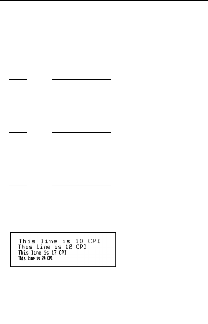
Programmer's Guide PcOS Series 150 Control Codes
Character Pitch
12/14/99 Rev G Page 31
Character Pitch
Function Begin 10 cpi character pitch
ASCII [DC2]
Hexadecimal 12H
Decimal <18>
IPCL &%F3
EPOS [ESC] [SP] <n>
Description This command sets ten character per inch print pitch.
Function Begin 12 cpi character pitch
ASCII [ESC] :
Hexadecimal 1BH 3AH
Decimal <27> <58>
IPCL &%F2
EPOS [ESC] [SP] <n>
Description This command sets 12 character per inch print pitch.
Function Begin 17 cpi character pitch
ASCII [SI]
Hexadecimal 0FH
Decimal <15>
IPCL &%F1
EPOS [ESC] [SP] <n>
Description This command sets 17 character per inch print pitch
Function Begin 24 cpi character pitch
ASCII [ESC] [SI]
Hexadecimal 1BH 0FH
Decimal <27> <15>
IPCL &%F4
EPOS [ESC] [SP] <n>
Description This command sets 24 character per inch print pitch
Figure 9 Examples of character print
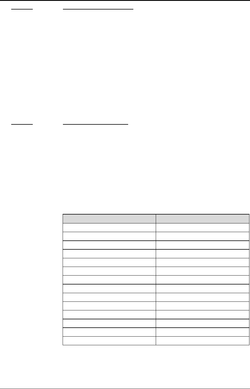
Control Codes PcOS Series 150 Programmer's Guide
Character Pitch
Page 32 Rev G12/14/99
Function Set specified character pitch
ASCII [ESC] [ P <n>
Hexadecimal 1BH 5BH 50H <n>
Decimal <27> <91> <80> <n>
IPCL &%F<n>
EPOS [ESC] [SP] <n>
Description This command sets characters per inch print pitch to <n>.
Where n = <8> selects 8 cpi &%F7
<10> selects 10 cpi &%F3
<12> selects 12 cpi &%F2
<15> selects 15 cpi &%F6
<17> selects 17 cpi &%F1
<20> selects 20 cpi &%F5
<24> selects 24 cpi &%F4
Function Set intercharacter spacing
Mode Global
ASCII [ESC] V <n>
Hexadecimal 1BH 56H <n>
Decimal <27> <86> <n>
IPCL none
EPOS [ESC] [SP] <n>
Description Set intercharacter spacing by adding white space between characters. The value
of <n> sets the spacing and ranges from zero to 11. The normal pitch set
commands set the intervalue to zero. The amount of space depends on the pitch
that was set. The following table specifies the amount of white space for each
pitch setting.
Pitch Spacing
HSD 8 cpi 1/80 * n
HSD 10 cpi 1/100 * n
HSD 12 cpi 1/120 * n
HSD 15 cpi 1/150 * n
HSD 17 cpi 1/171 * n
HSD 20 cpi 1/200 * n
HSD 24 cpi 1/240 * n
Utility/NLQ 8 cpi 1/150 * n
Utility/NLQ 10 cpi 1/120 * n
Utility/NLQ 12 cpi 1/144 * n
Utility/NLQ 15 cpi 1/180 * n
Utility/NLQ 17 cpi 1/205 * n
Utility/NLQ 20 cpi 1/240 * n
Utility/NLQ 24 cpi 1/288 * n
Table 11 Intercharacter spacing table
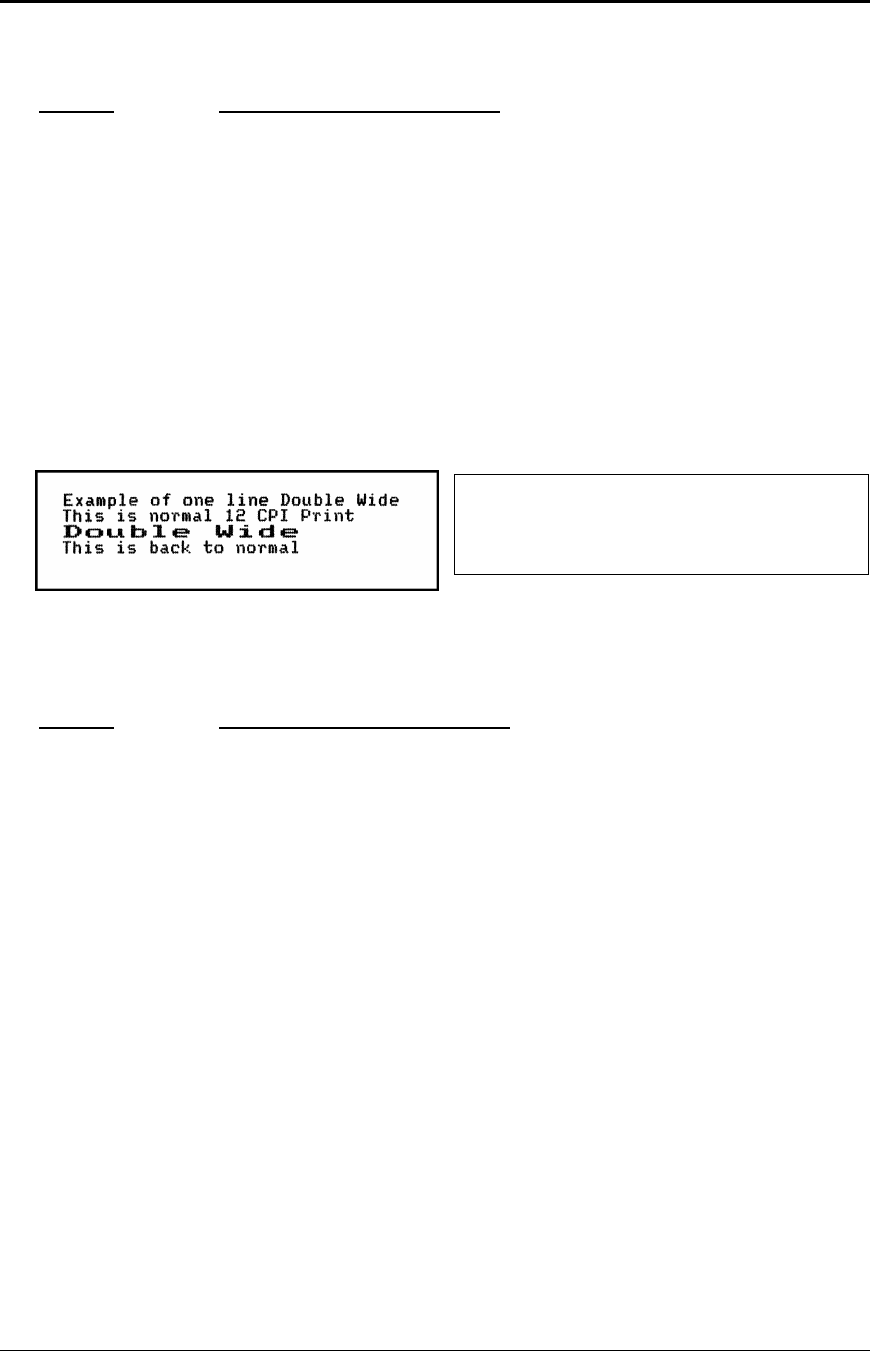
Programmer's Guide PcOS Series 150 Control Codes
Character Attributes
12/14/99 Rev G Page 33
Character Attribute Commands
Function Begin one-line double-wide print
ASCII [SO]
Hexadecimal 0EH
Decimal <14>
IPCL &%MW
EPOS none
Description This command causes subsequent characters to be printed at twice the currently
selected character width. For example ten cpi becomes five cpi, 17 cpi becomes
8.5 cpi, and so on. This command will remain in effect until:
a. a valid line terminator is received (CR, LF, or fine line feed);
b. the command is canceled; or
c. the maximum number of characters per line is reached and the printer
performs an auto print.
Function Cancel one-line double-wide print
ASCII [DC4]
Hexadecimal 14H
Decimal <20>
IPCL &%MN
EPOS none
Description This command cancels one-line double-wide mode set by the [SO] command
and allows single- and double-wide characters to be printed on the same line.
Figure 10 Example of one-line double-wide
print
Example of one line Double Wide[CR][LF]
This is normal 12 cpi Print[CR][LF]
[SO]
Double Wide[CR][LF]
This is back to normal[CR][LF]
Figure 11 Data sent to printer for one-line
double-wide print

Control Codes PcOS Series 150 Programmer's Guide
Character Attributes
Page 34 Rev G12/14/99
Function Multiline double-wide and double-high
ASCII [ESC] W <n>
Hexadecimal 1BH 57H <n>
Decimal <27> <87> <n>
IPCL &%FD, &%FS, &%FH (Note: Single-wide, double-high print is not available
in IPCL).
EPOS [ESC] ! <n>
Description This command controls multiline double-wide or double-high mode.
Where nspecifies the mode
0begins standard single-wide and single-high &%FS
1begins double-wide &%FD
2begins double-high none
3begins double-wide, double-high &%FH
Note: This command does not affect line spacing.
EPOS Note: [ESC] ! <n> performs a similar function; however, NLQ is not
available.
Where n-bits 76543210 Function
1------- Underline
--1----- Double-wide
---1---- Double-high
-------X Font: 1 = Utility, 0 = HSD
Function Set print style: double-wide, double-high, italic control
ASCII [ESC] [ @ [EOT] [NUL] <k> [NUL] <n> <m>
Hexadecimal 1BH 5BH 40H 04H 00H <k> 00H <n> <m>
Decimal <27> <91> <64> <04> <0> <k> <0> <n> <m>
IPCL &%DH Double-high, double-wide, and double-space
&%SH Single-high, single-wide, and single-space
Also, see [ESC] W.
Description This command sets double-wide, double-high, and italic print mode.
Where k-bits 76543210
----xxxx Italic control
0----0000 No change
1----0001 Italic On
2----0010 Italic Off
Where n-bits 76543210
----xxxx Height multiplier
0----0000 No change
1----0001 Single high
2----0010 Double high
xxxx---- Line spacing
00000---- No change
16 0001---- Single line feed
32 0010---- Double line feed
Where m-bits 76543210
----xxxx Width multiplier
0----0000 No change

Programmer's Guide PcOS Series 150 Control Codes
Character Attributes
12/14/99 Rev G Page 35
1----0001 Single-wide
2----0010 Double-wide

Control Codes PcOS Series 150 Programmer's Guide
Character Attributes
Page 36 Rev G12/14/99
Function Begin underline
ASCII [ESC] - <1>
Hexadecimal 1BH 2DH 01H
Decimal <27> <45> <1>
IPCL &%MU
EPOS [ESC] ! <n>
Description This command begins the underline print mode. All subsequent text and
leading spaces will be underlined. Trailing spaces are also underlined.
Note: Underline is not available in HSD mode. See page 30 for available
modes.
EPOS Note: [ESC]!<n> performs a similar function; however, NLQ is not
available.
Where n-bits 76543210 Function
1------- Underline
--1----- Double-wide
---1---- Double-high
-------X Font: 1 = Utility, 0 = HSD
Function End underline
ASCII [ESC] - <0>
Hexadecimal 1BH 2DH 00H
Decimal <27> <45> <0>
IPCL &%CU
EPOS none
Description This command ends underline print mode.
Function Begin overscore
ASCII [ESC] _ <1>
Hexadecimal 1BH 5FH 01H
Decimal <27> <95> <1>
IPCL &%MO
EPOS none
Description This command begins overscore print mode. All subsequent text and leading
spaces will be overscored. Trailing spaces are also overscored.
Note: Overscore is not available in HSD mode. See page 30 for available
modes.
Function End overscore
ASCII [ESC] _ <0>
Hexadecimal 1BH 5FH 00H
Decimal <27> <95> <0>
IPCL &%CO
EPOS none
Description This command ends overscore print mode.

Programmer's Guide PcOS Series 150 Control Codes
Character Attributes
12/14/99 Rev G Page 37
Function Begin enhanced print
ASCII [ESC] G
Hexadecimal 1BH 47H
Decimal <27> <71>
IPCL &%ME
EPOS [ESC] G <1>
Description This command begins enhanced print mode. All subsequent text will be printed
in enhanced print mode (two pass with a vertical offset). Enhanced printing
provides a deeper resolution of each character and may enhance multiple part
forms printing.
Note: This feature is not available in all print modes. See page 30 for available
modes.
Function End enhanced print
ASCII [ESC] H
Hexadecimal 1BH 48H
Decimal <27> <72>
IPCL &%CE
EPOS [ESC] G <0>
Description This command cancels enhanced print mode and returns to the currently
selected font.
Function Begin emphasized print
ASCII [ESC] E
Hexadecimal 1BH 45H
Decimal <27> <69>
IPCL &%MM
EPOS [ESC] E <1>
Description This command begins emphasized print mode (single pass with horizontal
offset). This print is bolder than normal print.
Function End emphasized print
ASCII [ESC] F
Hexadecimal 1BH 46H
Decimal <27> <70>
IPCL &%CM
EPOS [ESC] E <0>
Description This command cancels emphasized print mode.

Control Codes PcOS Series 150 Programmer's Guide
Character Attributes
Page 38 Rev G12/14/99
Function Select superscript
ASCII [ESC] S <0>
Hexadecimal 1BH 53H 00H
Decimal <27> <83> <0>
IPCL &%SP
EPOS none
Description This command selects superscript. All following characters will be printed half
size on the upper side of the print line.
Note: This feature is not available in all print modes. See page 30 for available
modes.
Function Select subscript
ASCII [ESC] S <1>
Hexadecimal 1BH 53H 01H
Decimal <27> <83> <1>
IPCL &%SB
EPOS none
Description This command selects subscript. All following characters will be printed half
size on the bottom side of the print line.
Note: This feature is not available in all print modes. See page 30 for available
modes.
Function End superscript or subscript
ASCII [ESC] T
Hexadecimal 1BH 54H
Decimal <27> <84>
IPCL &%SE
EPOS none
Description This command cancels superscript or subscript.
Function Begin italics
ASCII [ESC] % G
Hexadecimal 1BH 25H 47H
Decimal <27> <37> <71>
IPCL &%MI
EPOS [ESC] 4
Description This command begins italic print mode.
Note: Italics are not available in all print modes. See page 30 for available
modes.
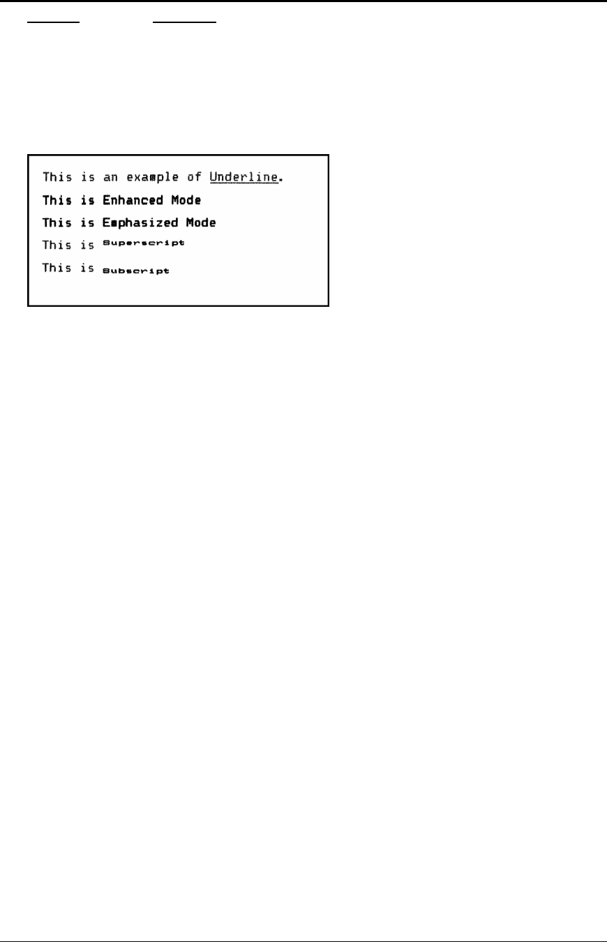
Programmer's Guide PcOS Series 150 Control Codes
Character Attributes
12/14/99 Rev G Page 39
Function End italics
ASCII [ESC] % H
Hexadecimal 1BH 25H 48H
Decimal <27> <37> <48>
IPCL &%CI
EPOS [ESC] 5
Description This command ends italic print mode.
Figure 12 Example of underline, enhanced, emphasized, superscript, and subscript print

Control Codes PcOS Series 150 Programmer's Guide
Rotated Print
Page 40 Rev G12/14/99
Print Rotation Commands
To provide printing flexibility on preprinted and various size forms, rotated print capability is
available in validation and receipt modes. Rotated print mode aligns the print in any of three 90
degree orientations.
In 90° and 270° rotated modes, the print data is first buffered by the printer, processed (rotated), and
then printed. As a result, the print process is slightly delayed. In 180° mode, the print is simply
inverted and mirrored.
Because the rotated 90° and 270° print buffer is limited to 1760 characters, the amount of rotated
print is also limited. The printer can support a limit of 22 lines of rotated print with a maximum line
length of 80 characters. The technique used by the Series 150 Printer is to receive all the print to be
rotated and convert it into graphics. This requires buffer space for all possible characters in each print
line. Each line has a fixed length buffer regardless of how much data is actually sent to the printer.
The printer will space fill the buffer for each line to the maximum size. As a result, a short line of two
characters will take as much buffer space as a long line.
To make the most efficient use of buffer space, the line length is predefined. The default line length is
80 characters, which leaves room for 22 lines. To allow longer lines to be printed, the line length can
be changed; however, no more than 22 lines with no more than 128 characters per line are allowed.
For example, if the line length is expanded to 128 characters per line, there is buffer space for
1760/128 or 13 lines.
Specifying the line length is also useful to determine where data is printed on forms. In rotated 90°
and 270° mode, the print field can be extended to print the complete line length specified. Extending
the line length is useful for printing forms such as checks where the form is fixed but the data can
change. This mode is called line formatted mode. In line formatted mode, the line length is set not by
the longest line entered but by the maximum line length. (Line lengths less than 80 will not print
more than 22 lines, only the format will be affected).
The space between lines is controlled by a line spacing table. The table is defined by the rotated print
line spacing ([ESC] u ...) command or by inserting [LF] or [ESC] J <n> commands in the rotated
data. The [ESC] u command specifies the number of dots to be added between each printed line. Each
line has an entry in the table. There is room for 22 lines in the table. The minimum spacing (and
default) is one dot or 1/80 inch between lines which results in a total of 10 dots in a line or 10/80 inch
(8 lines per inch).
The character cell is 7 x 9 with one dot of white space9 or a total cell size of 7 x 10. The cell is
printed at 80 dots per inch. If three dots are added, there will be a total of four dots, and the cell will
be 7 x 13. The following table specifies lines per inch for various numbers of inserted dots.
Number of dots added 01234567
Spacing specified 12345678
Cell size 7 x 10 7 x 11 7 x 12 7 x 13 7 x 14 7 x 15 7 x 16 7 x 17
Line spacing (inches) 0.125 0.1375 0.15 0.1625 0.175 0.1875 0.2 0.2125
Number lines per inch 87.27 6.67 6.15 5.71 5.33 5.0 4.7
Table 12 Rotated print spacing
9 Line graphic characters are 7 x 10 which allow touching characters as a default.

Programmer's Guide PcOS Series 150 Control Codes
Rotated Print
12/14/99 Rev G Page 41
If a [LF] is used to specify the line spacing, it overrides the default table and sets spacing to one dot
for eight lines per inch. If [ESC] J <n> is used, <n> specifies the spacing in n/216 (including the one
dot white space). Note: the finest resolution is still 1/80, n/216 will be rounded to the nearest n/80 and
the smallest value allowed will be 1/80.
In rotated 90° or 270° mode, the print is done in all-points-addressable (APA) graphics. The
intercharacter spacing is adjusted with the normal line spacing commands. The [ESC] 3 <n>
command is the most effective command for adjusting intercharacter spacing. Line spacing smaller
than 12 cpi will force the characters to overlap. (Spacing of 12 cpi is obtained with an [ESC] 3 <18>.)
When 90° or 270° rotation is selected, only normal text can be printed. Underline, enhanced,
emphasized, and other attributes will not function. See the chart on page 30 for a list of available
features.
In 180° rotation mode, all spacing commands are effective. This mode of operation simply inverts and
mirrors the print operation. All line spacing and print features are available. It should be noted that
the feed direction is not effected by any of the rotate commands.
Function Begin 90° rotated print
ASCII [ESC] r <1>
Hexadecimal 1BH 72H 01H
Decimal <27> <114> <1>
IPCL &%R1
EPOS [ESC] T <3>
Description Print data is entered normally from left to right, top to bottom. When an end
rotated print ([ESC] r <0>) command is received, the printer formats and prints
the data.
EPOS Note: The Series 150 Printer does not fully implement EPOS page
mode. The [ESC] T <n> command functions identically to the normal mode
[ESC] r <n> except the definition of <n> is different.
Function Begin 90° rotated print with line formatting
ASCII [ESC] r <5>
Hexadecimal 1BH 72H 05H
Decimal <27> <114> <5>
IPCL &%R5
EPOS [ESC] T <3>
Description Print data is entered normally from left to right, top to bottom. When an end
rotated print ([ESC] r <0>) command is received, the printer formats and prints
the data. This command differs from the [ESC] r <1> command in that the line
length is determined not by the longest line entered, but by the line length set
by the [ESC] s command. If input extends past the end of a line, it will line
wrap.

Control Codes PcOS Series 150 Programmer's Guide
Rotated Print
Page 42 Rev G12/14/99
Function Begin 270° rotated print
ASCII [ESC] r <3>
Hexadecimal 1BH 72H 03H
Decimal <27> <114> <3>
IPCL &%R3
EPOS [ESC] T <1>
Description Print data is entered normally from left to right, top to bottom. When an end
rotated print ([ESC] r <0>) command is received, the printer formats and prints
the data. The print will be rotated 270° according to the currently stored format
parameters.
EPOS Note: The Series 150 Printer does not implement EPOS page mode. The
[ESC] T <n> command functions identically to the normal mode [ESC] r <n>
except the definition of <n> is different.
Function Begin 270° rotated print with line formatting
ASCII [ESC] r <7>
Hexadecimal 1BH 72H 07H
Decimal <27> <114> <7>
IPCL &%R7
EPOS [ESC] T <1>
Description Print data is entered normally from left to right, top to bottom. When an end
rotated print ([ESC] r <0>) command is received, the printer formats and prints
the data. The print will be rotated 270° according to the currently stored format
parameters. This command differs from the [ESC] r <3> command by spacing
out the lines to the line length specified by the [ESC] s command. If input
extends past the end of a line, it will line wrap.
Function Begin 180° rotated print
ASCII [ESC] r <2>
Hexadecimal 1BH 72H 02H
Decimal <27> <114> <2>
IPCL &%R2
EPOS [ESC] { <1>
Description All subsequent lines will be rotated 180° and positioned at the opposite margin.
This command is effective on all stations including the journal. This command
will remain in effect until rotation is canceled with an end rotated print ([ESC]
r <0>) command, or a station select command is issued.
Note: The last line of print must be terminated with a line terminator before the
end rotated command is issued. Any characters in the print buffer that have not
been printed will not be printed. They will be printed unrotated when a line
terminator is received.

Programmer's Guide PcOS Series 150 Control Codes
Rotated Print
12/14/99 Rev G Page 43
Function End rotated print
ASCII [ESC] r <0>
Hexadecimal 1BH 72H 00H
Decimal <27> <114> <0>
IPCL &%R0
EPOS [ESC] { <0>
Description In 90° or 270° mode, this command prints the contents of the rotated print
buffer and returns to normal print orientation.
In 180° mode, the printer will return to normal print orientation. Characters in
the print buffer that have not been printed will not be printed.
Function Set rotated print line length
ASCII [ESC] s <n>
Hexadecimal 1BH 73H <n>
Decimal <27> <115> <n>
IPCL &%RL <m1> <m2><m3>
EPOS none
Description This command sets the print line length to be used in autoformat rotated print
mode. The maximum number of characters is 128 per line. The power on
default line length is 80 characters.
The number of available print lines is found by dividing 1760 by the number of
characters per line and rounding down to the nearest whole number. The
minimum number is 80 characters. Any value less than 80 will not allow any
additional lines to be printed. Values greater than 80 will limit the number of
lines to less than 22.

Control Codes PcOS Series 150 Programmer's Guide
Rotated Print
Page 44 Rev G12/14/99
Function Set rotated print line spacing
ASCII [ESC] u <n1> <m1> <n2> <m2> ... <ni> <mi> <0>
Hexadecimal 1BH 75H <n1> <m1> <n2> <m2> ... <ni> <mi> 00H
Decimal <27> <117> <n1> <m1> <n2> <m2> ... <ni> <mi> <0>
IPCL none
EPOS none
Description This command adjusts the line spacing for each rotated print line where ni is
the line number and mi is the spacing in dot columns (1/80 inch) from the
previous line.
For the first print line, the distance is calculated from the margin. An ni value
of 0 is used to terminate the command. Any unspecified spacing will be set to
one. This allows data to be accurately positioned on an inserted form. These
values will be used as a template for all subsequent rotated print. On power up,
all spacing is preset to 1/80 inch (n = 1, 8 lines per inch) for all lines. This
command is only effective in 90° and 270° rotation. It will remain in effect
until a new table is received or until the printer is power cycled. An [ESC] u
<0> will have the effect of setting all lines to one. This table can be overridden
by [LF] or [ESC] J <n> commands in the rotated print data.
The value of m can be from one to 127; n can be from one to 22.
Table 12 on 40 specifies the line spacing for this command.
Second line
Third line
Edge of form
Left margin
n=1, m
n=2, m
First line

Programmer's Guide PcOS Series 150 Control Codes
Graphic Mode
12/14/99 Rev G Page 45
Graphic Mode
The Series 150 Printer conforms to the full definition of IBM all-points-addressable (APA) graphic
commands. The printer will only print graphics that are 2.4 inches wide. This at times can make it
difficult to use off-the-shelf graphic generation programs.
If the Series 150 Printer is used with programs that convert text to graphics, the printer will be slower
than if the printer is sent ASCII text. The Series 150 Printer is supported by a Windows’ print driver
that will allow applications to select fonts that are supported by the printer.
The Series 150 Printer is not designed to print large quantities of graphical data. If the printer is
asked to print an excessive amount of black, it will break down the job into multiple steps. This
protects the printer but slows the printing time. The printer should not be requested to print a white
on black image.
Standard APA Graphics
Function Print single-density graphics (60 h x 72 v dpi)
ASCII [ESC] K <n>1 <n>2
Hexadecimal 1BH 4BH <n>1 <n>2
Decimal <27> <75> <n>1 <n>2
IPCL none
Description This command prints n1 + 256 * n2 bytes of single-density graphics (60
dpi).
Function Print half-speed double-density graphics (120 h x 72 v dpi)
ASCII [ESC] L <n>1 <n>2
Hexadecimal 1BH 4CH <n>1 <n>2
Decimal <27> <76> <n>1 <n>2
IPCL none
Description This command prints n1 + 256 * n2 bytes of double-density graphics (120
dpi) at half-speed allowing full and half dots to be printed.
Function Print full-speed double-density graphics (120 h x 72 v dpi)
ASCII [ESC] Y <n>1 <n>2
Hexadecimal 1BH 59H <n>1 <n>2
Decimal <27> <89> <n>1 <n>2
IPCL none
Description This command prints n1 + 256 * n2 bytes of double-density graphics (120
dpi) at full speed with no consecutive dots. (Full-speed double-density
graphic mode is generally used to print 120 h by 144 v dpi resolutions in
two passes).

Control Codes PcOS Series 150 Programmer's Guide
Graphic Mode
Page 46 Rev G12/14/99
Function Print quad-density graphics (240 h x 72 v dpi)
ASCII [ESC] Z <n>1 <n>2
Hexadecimal 1BH 5AH <n>1 <n>2
Decimal <27> <90> <n>1 <n>2
IPCL none
Description This command prints n1 + 256 * n2 bytes of quad-density graphics (240
dpi) at half speed with no consecutive dots. (Quad-density graphic mode is
generally used to print 240 h by 144 v dpi resolutions in two passes).
Function Print graphics in mode <m> (60 h/120 h/240 h x 72 v dpi)
ASCII [ESC] * <m> <n>1 <n>2
Hexadecimal 1BH 2AH <m> <n>1 <n>2
Decimal <27> <42> <m> <n>1 <n>2
IPCL none
Description This command selects one of the three above graphics modes as specified
by <m>.
Where <m> 060 dpi Full speed 8-bit slices
1120 dpi Half speed 8-bit slices
2120 dpi Full speed 8-bit slices
3240 dpi Full speed 8-bit slices
480 dpi Full speed 8-bit slices
572 dpi Full speed 8-bit slices
690 dpi Full speed 8-bit slices
7144 dpi Full speed 8-bit slices
8,9,11,12,13,14,16 Not supported
Function Reassign graphic mode <m>
ASCII [ESC] ? <m> <n>
Hexadecimal 1BH 3FH <m> <n>
Decimal <27> <63> <m> <n>
IPCL none
Description This command reassigns graphic mode <m> to resolution <n>. Possible
values for <m> are K, L, Y or Z. Resolutions <n> are 0 through 7 as
follows:
Where <m> 060 dpi Full speed 8-bit slices Default for K
1120 dpi Half speed 8-bit slices Default for L
2120 dpi Full speed 8-bit slices Default for Y
3240 dpi Full speed 8-bit slices Default for Z
480 dpi Full speed 8-bit slices
572 dpi Full speed 8-bit slices
690 dpi Full speed 8-bit slices
7144 dpi Full speed 8-bit slices

Programmer's Guide PcOS Series 150 Control Codes
Graphic Mode
12/14/99 Rev G Page 47
Function Begin unidirectional print
ASCII [ESC] U <1>
Hexadecimal 1BH 55H 01H
Decimal <27> <85> <1>
IPCL &%GU
EPOS [ESC] U <1>
Description This command prints all data in unidirectional print mode to improve line
to line registration for graphical data.
Note: This command should be canceled before normal text is printed. It
will slow printing time if it is not canceled.
Function Begin bidirectional print
ASCII [ESC] U <0>
Hexadecimal 1BH 55H 00H
Decimal <27> <85> <0>
IPCL &%GB
EPOS [ESC] U <0>
Description This command prints all data in bidirectional, logic-seeking print mode.

Control Codes PcOS Series 150 Programmer's Guide
Bar codes
Page 48 Rev G12/14/99
Bar codes
The Series 150 Printer has the ability to print bar codes. The printer will print one of five formats,
Interleaved 2 of 5, Code 39, Code 128, UPC A, and EAN-13. The host does not need to form the
graphic image for these bar codes. The host need only send the printer the information to be bar
coded, and a graphic will be generated. Bar codes can be printed in a high-resolution normal mode or
a fast, high-speed mode. The normal mode is more readable than the high speed mode. (See the
[ESC] [EM] B command on the next page for setting the bar code height and print speed.)
Function Print bar code
ASCII [ESC] b <n> {information} [ETX]
Hexadecimal 1BH 62H <n>... 03H
Decimal <27> <98> <n> ... <3>
IPCL &%25 ... [CR] Interleaved 2 of 5
&%39 ... [CR] Code 39
&%12 ... [CR] Code 128
&%UP ... [CR] UPC A
&%UE ... [CR] UPC E
&%EA .. [CR] EAN-13
&%E8 ... [CR] EAN-8
&%93 ... [CR] Code 93
&%HB<n> .. Hollerith10
EPOS [ESC] b <n> or [GS] k <n>
Description This command prints the information as a bar code. The bar code will be
centered on the print zone.
Where n 0Interleaved 2 of 5 Numeric (0-9) only; must be an even number of
digits
1Code 39 26 uppercase letters (A-Z) and 10 digits (0-9)
2Code 128 Three sets of 106 different characters
3UPC A Numeric (0-9) only; 11 digits
4EAN-13 Numeric (0-9) only; 12 digits
5UPC E Numeric (0-9) only; 11 digits
6EAN-8 Numeric (0-9) only; 7 digits
7Code 93 26 letters, 10 digits (0-9), and 7 special characters
10 Hollerith ASCII data up to 16 digits
Interleaved 2 of 5 is a high-density, self-checking, continuous, numeric bar code. It is mainly used
where fixed length numeric fields are required. The data field must be an even
number of characters. If an odd data field is sent to the printer, it will be zero
padded. Due to space limitations, only 16 characters can be printed. (Note:
Interleaved 2 of 5 does not read well in fast mode.)
Code 39 is an alphanumeric bar code. It is a discrete, self-checking, variable length
code. The complete data field is printed. Due to space limitations, only eight
characters can be printed. If illegal characters are passed to the printer, they
will be converted to legal codes, i.e., a → A.
Code 128 is an alphanumeric bar code. It is a high-density, variable length, continuous
code that employs multiple element widths. Code 128 has three possible start
codes. The start code defines the set as Code A, B, or C. The first character in
10 The Hollerith bar code is only available on custom configurations.

Programmer's Guide PcOS Series 150 Control Codes
Bar codes
12/14/99 Rev G Page 49
the data field defines the code set, Start Code A = <135>, Code B = <136>, and
Code C = <137>. The complete data field is printed by the printer. Due to space
limitations, only nine characters can be printed. A check digit is generated by
the printer.
Code 128 Note The “A” space is defined as a <0>, which makes programming difficult and
causes control character conflicts for the printer. To solve the problem, the
Series 150 Printer subtracts 32 from all characters that are to be included in the
bar code. In the Code 128 definition, an “A” is <33>; however, the printer will
convert an ASCII “A” (<65>) to a <33> internally. This sets Code 128C and
the start codes off by 32.
UPC A is a fixed length, numeric, continuous code that employs four element widths.
The printer supports Universal Product Code Version A, E, EAN-8, and EAN-
13. Version A encodes 11 digits. Typically, the UPC A format starts with a
number system digit, five-digit manufacturer’s code, five-digit product code,
and a check digit. The printer makes no assumptions about any of the codes
except the check digit. The printer will print a UPC bar code with the 11 digits
sent to it and generate the check digit. If fewer than 11 digits are sent, the
remaining digits will be zeroes. The printer will print a UPC that is about
130% the size of the UPC nominal standard, which provides optimal
readability.
UPC E is a zero suppression version of UPC. The printer requires that the first digit is
zero for number system zero. If it is not zero, the bar code is not printed. The
printer does the compression based on the compression rules for UPC-E. The
printer will print a UPC bar code based on the 11 digits sent to it and generate
the check digit. If fewer than 11 digits are sent, the remaining digits will be
zeroes. The printer will print a UPC that is about 130% the size of the UPC
nominal standard, which provides optimal readability.
EAN-8 is a fixed length, numeric, continuous code that employs four element widths.
The printer supports EAN-8, which is a superset of UPC that encodes seven
digits. The printer will print an EAN-8 bar code with the seven digits sent to it
and generate the check digit. If fewer than seven digits are sent, the remaining
digits will be zeroes. The printer will print an EAN-8 bar code that is about
130% the size of the nominal standard which provides optimal readability.
EAN-13 This is a fixed length, numeric, continuous code that employs four element
widths. The printer supports EAN-13 which is a superset of UPC which
encodes 12 digits. Typically, the format starts with a number set digit, which
defines how the next six digits are encoded. The next five digits have fixed
encoding. The last is a check digit. The printer will print an EAN-13 bar code
with the 12 digits sent to it and generate the check digit. If fewer than 12 digits
are sent, the remaining digits will be zeroes. The printer will print an EAN-13
bar code that is about 130% the size of the nominal standard, which provides
optimal readability.
Code 93 is an alphanumeric, variable length bar code. The complete data field is printed
by the printer. Due to space limitations, only 11 characters can be printed.
Hollerith is variable length, ASCII data that is intended for use with optical mark
readers. The printer will print a grid of encoded rectangles arranged
horizontally across the paper.
Notes A [CR] may also be used in place of the [ETX] to end the bar code data field.
Only information that is usable in a particular bar code will be printed.

Control Codes PcOS Series 150 Programmer's Guide
Bar codes
Page 50 Rev G12/14/99
Function Bar code height
ASCII [ESC] [EM] B <n>
Hexadecimal 1BH 19H 42H <n>
Decimal <27> <25> <66> <n>
IPCL &%BH <m1> <m2>
EPOS [GS] h <n>
Description This command sets the bar code height. Where <n> is the number of print
passes, each pass is about 0.11 inch high. If n = <0>, the printer returns to the
default values of four passes for all except UPC, which has default values of
seven. Any value from zero to nine may be specified.
Function Set bar code justification and human readable number print modes
ASCII [ESC] [EM] J <n>
Hexadecimal 1BH 19H 4AH <n>
Decimal <27> <25> <74> <n>
IPCL &%BJ <m1> <m2>
EPOS none
The power on default is center justified with numbers on UPC bar codes.
Note: This command only effects bar code printing.
Description This command selects the operation of the bar code justification and number
printing.
Where n-bits nIPCL 76543210
------xx Justification
0 00 ------00 Left
1 01 ------01 Center
2 02 ------10 Right
----xx-- Human readable
0 00 ----00-- No numbers
4 04 ----01-- Numbers on UPC bar codes
8 08 ----10-- Numbers on non-UPC bar codes
12 12 ----11-- Numbers on all bar codes

Programmer's Guide PcOS Series 150 Control Codes
Receipt Paper Out Sensor
12/14/99 Rev G Page 51
Receipt Paper Out Sensor
The paper out sensor in the Series 150 Printer, senses when the paper is exhausted. When
the printer generates a paper out fault, the printer stops printing and goes off-line. If the
printer is off-line, inquires may not be accepted. To prevent the printer from going off-line
when paper out is sensed, you can send an [ESC] 8.
Function Disable paper out sensor
ASCII [ESC] 8
Hexadecimal 1BH 38H
Decimal <27> <56>
IPCL &%PF
EPOS none
Description This command disables paper out sensing and is intended to
temporally disable the paper out sensor. The printer will not stop
printing or go off-line when paper out is sensed. The [ENQ]
commands will still return paper out status.
Function Enable paper out sensor
ASCII [ESC] 9
Hexadecimal 1BH 39H
Decimal <27> <57>
IPCL &%PO
EPOS none
Description This command enables paper sensing and is intended to reverse the
effect of the disabled paper out sensor command. If the printer is out of
paper when this command is issued, it will go off-line.

Control Codes PcOS Series 150 Programmer's Guide
Validation Operation
Page 52 Rev G12/14/99
Validation Operation
The form is inserted from the top and extends out the left side and/or top of the printer. It rests on
a fixed stop. A maximum of 16 lines at 40 characters can be printed on a form. In this manual,
top insertion will be termed validation mode.
Function Open for validation
ASCII [ESC] [DC1]
Hexadecimal 1BH 11H
Decimal <27> <17>
IPCL &%VO
EPOS [ESC] c 0 <n>
Description This command opens the form compensation assembly for validation. No
automatic validation form sensing is performed. The application must poll
the printer for validation forms present and then issue a close
compensation command.
Function Close for validation
ASCII [ESC] [DC3]
Hexadecimal 1BH 13H
Decimal <27> <19>
IPCL &%VC
EPOS [ESC] c 0 <n>
Description This command closes the form compensation assembly for validation. No
automatic validation form sensing is performed.
Function Close for validation when form is sensed
ASCII [ESC] [DC4]
Hexadecimal 1BH 14H
Decimal <27> <20>
IPCL &%VS
EPOS [ESC] c 0 <n>
Description This command closes the form compensation assembly for automatic
validation form sensing by the printer.

Programmer's Guide PcOS Series 150 Control Codes
Validation Operation
12/14/99 Rev G Page 53
Validation Operation Control
The Series 150 Printer has several features that can be altered during operation. For example, the
time delay between when a form is sensed and when the form clamp is activated can be changed.
This allows the operation of the printer to be tailored to the application and the form being used.
All feature control commands are extensions of the [ESC] [EM] sequence. They are defined as
follows.
Function Validation clamp delay
ASCII [ESC] [EM] C <n>
Hexadecimal 1BH 19H 43H <n>
Decimal <27> <25> <67> <n>
IPCL &%ZC <m1> <m2>
EPOS [ESC] f
Description This command sets the clamp delay which is the time between when the
form is sensed and when it is clamped. (Only the least four bits are used.)
The default is configurable.
Where <n> 0 = 0 ms
1 = 50 ms
2 = 150 ms, and so on until
15 = 750 ms
Note: Once issued, the value will be used until the printer is power cycled
or the command is reissued.
Function Set validation time-out
ASCII [ESC] [EM] V <n>
Hexadecimal 1BH 19H 56H <n>
Decimal <27> <25> <86> <n>
IPCL &%ZV <m1> <m2>
EPOS [ESC] f
Description This command sets the time-out after a top validation command with
autosense is issued and the printer returns to receipt mode.
Where <n> is the delay in one minute increments; minimum is one
minute; maximum is 15 minutes. If <n> = 0, the delay is set to no time-out
(waits forever). The default is configurable.

Control Codes PcOS Series 150 Programmer's Guide
Validation Operation
Page 54 Rev G12/14/99
Function Set left/right print margin
ASCII [ESC] X <n1> <n2>
Hexadecimal 1BH 58H <n1> <n2>
Decimal <27> <88> <n1> <n2>
IPCL none
EPOS [ESC] l or [ESC] Q
Description Set left and right print margin in characters from the home position.
Where n1 = Left margin
n2 = Right margin
The absolute position depends on the current print pitch.
8 cpi 10 cpi 12 cpi 15 cpi 17.1 cpi 20 cpi 24 cpi
Maximum
Columns
18 23 28 35 40 46 56
<n1> 1 to 18 1 to 23 1 to 28 1 to 35 1 to 40 1 to 46 1 to 56
<n2> <n1>+2
to 18 <n1>+2
to 23 <n1>+3
to 28 <n1>+3
to 35 <n1>+4
to 40 <n1>+4
to 46 <n1>+4
to 56
If the left and right margins are set to the right of the current horizontal
position, the new left and right margins become valid in the same line.
If the left margin is set to the left of the current horizontal position and the
right margin to the right of the current horizontal position, the right
margin becomes valid in the same line, but the left margin setting becomes
valid in the next line.
When the left and right margins are set to the left of the current horizontal
position, both left and right margin settings appear to become valid in the
next line. This is because an AUTO CR is performed by the following data.

Programmer's Guide PcOS Series 150 Control Codes
Miscellaneous Control
12/14/99 Rev G Page 55
Miscellaneous Control
Function Clear print buffer
ASCII [CAN]
Hexadecimal 18H
Decimal <24>
IPCL &%RP
EPOS [CAN]
Description This command clears any unprinted information in the printer received before
the [CAN].
If the input buffer is not being processed because the printer is out of paper or
the form is not inserted, the [CAN] command will not be processed until after
the error is cleared.
The [CAN] command does not restore default conditions. It only clears the
print buffers.
Function Open cash drawer
ASCII [ESC] x <n>
Hexadecimal 1BH 78H <n>
Decimal <27> <120> <n>
IPCL &%D1 for Cash Drawer 1
IPCL &%D2 for Cash Drawer 2
EPOS [ESC] p
Description This command energizes cash drawer n for 150 ms. Where <n> = <1> (01H) or
1 (31H) for Cash Drawer 1 and <n> = <2> (02H) or 2 (32H) for Cash Drawer
2.
The time period the drawer is activated can be changed in the configuration
menu. The activation time can be set from 25 to 250 ms.
Note: The open cash drawer commands are processed as part of print data.
They are not processed until they are found in the input buffer by the print
processor. They are not immediate commands.
Note: Cash Drawer 2 is factory configurable in one of two modes. Either Pin 1
or 5 is active depending on an internal jumper setting. The factory default is
Pin 1. Cash Drawer 1 is always on Pin 5.
The cash drawer status is defined as an open circuit for drawer closed.

Control Codes PcOS Series 150 Programmer's Guide
Miscellaneous Control
Page 56 Rev G12/14/99
Function Query marker
ASCII [ESC] q <n>
Hexadecimal 1BH 71H <n>
Decimal <27> <113>
IPCL none
EPOS none
Function Return status to host
Serial/IEEE1284 Parallel, non-IEEE 1284
Response [SOH] <n>… Not supported via PE
Description This command can be placed in the print data and, when processed by the
printer, will return a progress status marker. The value of <n> can be any
8-bit value. It is returned to the host unaltered. The intent is for it to be a
sequence number. This command can be used to track the print progress of
the printer or verify that the data has been printed.
Note: This command is a line terminator that causes the printer to print all
previous data. If a normal line terminator (like a [CR]) is not supplied,
right justify and autocenter will not function correctly. All data will be left
justified. [ESC] q does not perform a [CR] or [LF] function.

Programmer's Guide PcOS Series 150 Control Codes
Miscellaneous Control
12/14/99 Rev G Page 57
Function Print suppress and data pass through
ASCII [ESC] < <n>
Hexadecimal 1BH 3CH <n>
Decimal <27> <60> <n>
IPCL &%PT <n>
EPOS [ESC] = <n>
Description This command provides print suppress and data pass through features.
Where Bit 0 Printer select
Bit 1 Pass through On
Bits 2-7 Undefined
If Bit 0 is clear, the printer will stop processing data. If Bit 1 is set, the data
will be passed through the printer and sent out on the serial port.
Notes: The pass through command is processed as part of print data. The pass
through command is not processed until it is found in the input buffer by the
print processor. It is not an immediate command. The printer must be on-line
and ready to activate the command.
The operation of the command can be altered by the print suppress
configuration.
Function Control feature commands
ASCII [ESC] y <n>
Hexadecimal 1BH 79H <n>
Decimal <27> <121> <n>
IPCL &%Y0 through 8
EPOS [ESC] y <n>
Where n 0 Disables quiet mode operation
1 Enables quiet mode operation
2 Reinitializes the printer and forces IBM mode
3 Reinitializes the printer and forces EPOS mode
4 Disables IPCL commands
5 Enables IPCL commands
Note: Once disabled, this command will not be a valid IPCL code.
8 Enables extended diagnostics
Description This command enables and disables command set features.
It is possible that the IPCL commands will interfere with print data. If this is
the case, they can be disabled with an [ESC] y <4>.
Notes: Quiet mode operation prints by making two passes for every pass in
normal mode. It generates less noise because only half the print wires are
activated in each pass. This mode is very slow and should only be used if quiet
operation is needed.
ESC y <2> and <3> allow the printer to switch between Normal and EPOS
modes. When the switch takes place, the current print buffer is printed and the
printer reinitializes. These commands do not permanently change the
configuration. A power on reset will restore the mode that was configured in
menu mode. A reset by command or from the INIT pin will not restore the
mode.
EPOS Note: This command is active in EPOS mode; however, Mode 5 is
disabled.

Control Codes PcOS Series 150 Programmer's Guide
Miscellaneous Control
Page 58 Rev G12/14/99
Function Enable Dynamic Response
ASCII [ESC] w <n>
Hexadecimal 1BH 77H <n>
Decimal <27> <119> <n>
IPCL none
EPOS [GS] a <n>
Where n defines the features that cause dynamic responses.
Bit 0 Cash Drawer 0 ACK/NAK <1>
Bit 1 Cash Drawer 1 ACK/NAK <2>
Bit 2 Paper out status ACK/NAK <4>
Bit 3 Form in sensor ACK/NAK <5>
Bit 6 Form clamp status ACK/NAK <7>
Dynamic status can be used to allow the host to sense status changes without
sending repeated inquire ([ENQ]) commands. The operation of the dynamic
response varies depending on the configuration of the printer. If the printer is
configured for Serial or IEEE 1284 operation, more than one status can be
sensed as the printer will respond to status changes as if an [ENQ] were issued.
In parallel mode, only one status should be requested. If more than one bit is
active, the resulting status on the paper error (PE) signal will not be defined.
Note: Power up default is paper out on PE signal.
Function Activate cutter
ASCII [ESC] v
Hexadecimal 1BH 76H
Decimal <27> <118>
IPCL &%FC Cut
EPOS [ESC] m or [ESC] I
Description This command cuts the receipt tape above the current print line.
Note: This command is only effective on printers with a knife.

Programmer's Guide PcOS Series 150 Control Codes
Printer Status Set/Inquire
12/14/99 Rev G Page 59
Printer Status Set/Inquire
The Series 150 Printer is designed to be used as part of an automated system where the host computer
makes every attempt to correct problems with the printer. In addition, the host application requires
that it be able to obtain more information from the printer than is typical of normal computer printers.
A normal computer printer does not have to deal with cash drawers or validation. As a result, the
standard printer protocol must be extended to address the additional features of a POS printer.
The Series 150 Printer has defined a set of status inquiry commands that will allow a host to obtain
information about the printer and devices connected to it. The method chosen to interact with the
computer is designed to allow a reasonable approach to the host application. It will not always be
possible for an existing application to use the inquire commands unless the communication drivers
are available to the programmer.
All inquire commands require a response from the printer. For this reason, the parallel, non-IEEE
1284; IEEE 1284; and serial operation of inquire commands are different. In serial and parallel,
IEEE 1284 modes, all inquire commands are responded to by an acknowledged (ACK) or not
acknowledged (NAK) and then the command ID. In parallel non-IEEE 1284 operation, the paper
error (PE) signal is driven as a response to an inquire.
Parallel, Non-IEEE 1284 Mode Inquire
There are several status inquiry commands and inquire control commands. The inquire character
is treated differently from all other characters received by the printer. Under normal operating
conditions, all information that is sent to the printer is received and placed in a holding buffer.
The information stays in the holding buffer until the printer prints or interprets it.
The inquire command in non-IEEE 1284 mode presents a few problems for the printer to decode.
In parallel mode, the inquire character is intercepted before it is placed in the print buffer. The
next character is looked at to determine if it is a valid inquire command. If it is valid or a
graphic, further input is then blocked by not removing the busy status. The buffer is then emptied
by the printer during normal operation. If the inquire was false, the command decoder processes
a command. If an inquire is found in the data stream at this time, input is unblocked and normal
operation is resumed. The printer is unaffected by this unintended operation except that the
buffer efficiency is reduced. If the inquire was real, the inquire is processed. This ensures that the
response to the inquire is synchronized with the inquire request and that no false inquires are
processed.
In parallel, non-IEEE 1284 operation, there is no easy way to return complex information to the
host. For this reason, the paper error (PE) signal is used for inquire responses. The fault signal
will not be asserted by inquire requests. If a true PE is being signaled, the fault line will also be
driven. It is, therefore, possible to distinguish between a paper error and an inquire response.
In parallel mode, the printer will respond to the inquire before the parallel sequence is complete.
In other words, when the parallel port acknowledges the ID part of the inquire sequence, the PE
signal is valid. The host must, however, remember what status was requested as the printer has
no way of signaling that information. In addition, the host must not interpret the PE signal as an
error but as a response to an inquire. There are two ways in which inquire responses can be
signaled. The PE can be static or dynamic. When a dynamic PE occurs, the inquiry is sent once,
and the PE signal follows the requested status. If the PE remains static, the status will not
change.

Control Codes PcOS Series 150 Programmer's Guide
Printer Status Set/Inquire
Page 60 Rev G12/14/99
Receipt paper status is always dynamic. If the PE signal is to be returned to the valid paper error
state, an [ENQ] <4> should be issued when all other inquires are completed.
PE
DATA
STROBE
BUSY
ACK
Valid
ID Next
Figure 13 Paper-error to inquire-request timing
Serial Mode Inquire
In serial mode, inquires are not handled any differently than other commands. All inquire
commands require a response from the printer and are responded to by an acknowledged (ACK)
or not acknowledged (NAK) and then the command ID.
The serial ACK or NAK responses are always uniform and followed with a command ID. This
makes the design of the host application easier because the response can be identified and the
same format is always followed.
The printer always accepts serial data. When the printer is off-line, serial data is still accepted. It
is possible to send inquire commands to the printer even if it is off-line. Because inquire
commands are processed before they go in the buffer, the printer will respond even when it is
busy printing.
In serial mode, it is desirable that the response to an inquire be received by the host before
another inquire command is issued to the printer. When the printer receives an inquire, it must
generate a response. If inquires are sent to the printer too fast, the printer could overrun its output
buffer.
Parallel, IEEE 1284 Mode Inquire
In parallel, IEEE 1284 mode, there is a way to return status information to the host. After the
host makes an inquire request, the host can activate parallel, IEEE 1284 Mode 0 reverse channel
and wait for a response from the printer. The response to the inquire is identical to serial mode.
The printer will always accept IEEE 1284 reverse channel requests but will not accept inquire
commands when off-line. It is possible to obtain status when off-line by placing the printer in
dynamic response mode before the printer goes off-line. The IEEE 1284 reverse channel will
then respond to status changes even if the printer is off-line.
Dynamic Response Mode
Dynamic status, [ESC] w <n>, can be used to allow the host to sense status changes without
sending repeated inquiry commands. The operation of the dynamic response varies depending on
the configuration of the printer. If the printer is configured for serial or parallel, IEEE 1284
operation, more than one status can be sensed as the printer will respond to status changes as if

Programmer's Guide PcOS Series 150 Control Codes
Printer Status Set/Inquire
12/14/99 Rev G Page 61
an [ENQ] were issued. In parallel mode, only one status should be requested. If more than one bit
is active, the resulting status on the paper error (PE) signal will not be defined. The reply to
dynamic responses is the same as for inquire commands. That is, if the cash drawer status is to be
sensed, the PE or ACK/NAK will be the same as for inquire commands.

Control Codes PcOS Series 150 Programmer's Guide
Printer Status Set/Inquire
Page 62 Rev G12/14/99
Inquire Commands
Function Inquire printer status
ASCII [ENQ] <n>
Hexadecimal 05H <n>
Decimal <5> <n>
IPCL none
EPOS [GS] r or [DLE] [ENQ] or [DLE] [EOT]
Description This command inquires as to the printer’s status and returns the result. The
following inquires are defined.
Note: If the printer is off-line, inquires may not be accepted.
Function Inquire Cash Drawer 1 status
ASCII [ENQ] <1>
Hexadecimal 05H 01H
Decimal <5> <1>
Function Cash Drawer 1 status
Serial/Parallel, IEEE 1284 Parallel, non-IEEE 1284
Response ACK <1> (06H 01H) PE low
Cash Drawer 1 is closed.
NAK <1> (15H 01H) PE high
Cash Drawer 1 is open.
The cash drawer status is defined as open circuit being drawer closed.
Function Inquire Cash Drawer 2 status
ASCII [ENQ] <2>
Hexadecimal 05H 02H
Decimal <5> <2>
Function Cash Drawer 2 status
Serial/Parallel, IEEE 1284 Parallel, non-IEEE 1284
Response ACK <2> (06H 02H) PE low
Cash Drawer 2 is closed.
NAK <2> (15H 02H) PE high
Cash Drawer 2 is open.
The cash drawer status is defined as open circuit being drawer closed.
Function Inquire receipt-paper out
ASCII [ENQ] <4>
Hexadecimal 05H 04H
Decimal <5> <4>
Function Receipt-paper out
Serial/Parallel, IEEE 1284 Parallel, non-IEEE 1284
Response ACK <4> (06H 04H) PE low
There is receipt paper.
NAK <4> (15H 04H) PE high
The receipt paper is exhausted.

Programmer's Guide PcOS Series 150 Control Codes
Printer Status Set/Inquire
12/14/99 Rev G Page 63
Function Inquire form position sensor status
ASCII [ENQ] <6>
Hexadecimal 05H 06H
Decimal <5> <6>
Function Is the form position sensor detecting a form?
Serial/Parallel, IEEE 1284 Parallel, non-IEEE 1284
Response ACK <6> (06H 06H) PE low
The position sensor is clear.
(No form present.)
NAK <6> (15H 06H) PE high
The form position sensor is
blocked. (There is a form.)
Function Inquire form clamp status
ASCII [ENQ] <7>
Hexadecimal 05H 07H
Decimal <5> <7>
Function Inquire whether the form clamp is closed
Serial/Parallel, IEEE 1284 Parallel, non-IEEE 1284
Response ACK <7> (06H 07H) PE low
The clamp is closed.
NAK <7> (15H 07H) PE high
The clamp is not closed.
(It is open or in jam position.)
Function Is the buffer empty? Clear IEEE 1284 buffer.
ASCII [ENQ] <9>
Hexadecimal 05H 09H
Decimal <5> <9>
Function This command allows the host to know when the print buffer is
empty. If IEEE 1284 is active, this command also clears the
response buffer.
Serial/Parallel, IEEE 1284 Parallel, non-IEEE 1284
Response ACK <9> (06H 09H) PE low
The buffer is empty.
NAK <9> (15H 09H) PE high
The buffer is not empty.

Control Codes PcOS Series 150 Programmer's Guide
Printer Status Set/Inquire
Page 64 Rev G12/14/99
Function Request printer reset
ASCII [ENQ] <10>
Hexadecimal 05H 0AH
Decimal <5> <10>
Function Reset printer
Serial Parallel mode
Response ACK <10> (06H 0AH) No response in parallel mode.
The command was accepted.
NAK <10> (15H 0AH)
The command was rejected.
Description This command is similar to asking for a power-on reset except no
internal diagnostics are run. The internal print buffer will be cleared.
The printer will be ready to except new information when the
acknowledged (ACK) response is sent. In parallel mode, the INIT
signal should be used because this command will be rejected. (In
serial/parallel mode, the command will also be rejected).
Function Inquire power cycle status
ASCII [ENQ] <11>
Hexadecimal 05H 0BH
Decimal <5> <11>
Function Has the printer been power cycled since the last request?
Serial/Parallel, IEEE 1284 Parallel, non-IEEE 1284
Response ACK <11> (06H 0BH) PE low
Printer power has been cycled
since last [ENQ] <11>.
NAK <5> (15H 0BH) PE high
Printer has not power cycled
since last [ENQ] <11>.
Description The first time after a reset this command will return [ACK] <11>, after
that the command will return [NAK] <11>. This command allows the
application to determine if the printer has been power cycled and needs to
be reinitialized. The [ENQ] <10> command and the INIT signal on the
parallel port will both cause the printer to return power-up status.

Programmer's Guide PcOS Series 150 Control Codes
Printer Status Set/Inquire
12/14/99 Rev G Page 65
Function Inquire printer state
ASCII [ENQ] <15>
Hexadecimal 05H 0FH
Decimal <5> <15>
Function Returns current printer state
Serial/Parallel, IEEE1284 Parallel, non-IEEE 1284
Response [ACK] <15> <n> <r1> <r2>… Not supported via PE
Where <15> is the echo of the command ID.
n = number of return bytes + 40 (to prevent confusion with
XON/XOFF).
<r1>: Bit 0 = Form clamp closed
Bit 1 = Undefined
Bit 2 = Receipt paper out
Bit 3 = Undefined
Bit 4 = In error state (Waiting for error to be cleared)
Bit 5 = Undefined
Bit 6 = 1 always
Bit 7 = 0 always
<r2>: Forms processing state
040H No forms processing
044H Waiting to enter validation mode or for the paper path to be
cleared to enter validation mode
045H Waiting for an internal delay time-out (auto clear)
Other states may be active but will automatically be cleared.

Control Codes PcOS Series 150 Programmer's Guide
Printer Status Set/Inquire
Page 66 Rev G12/14/99
Function Inquire all printer status
ASCII [ENQ] <20>
Hexadecimal 05H 14H
Decimal <5> <20>
Function Returns all status flags
Serial/Parallel, IEEE1284 Parallel, non-IEEE 1284
Response [ACK] <20> <n> <r1> <r2>… Not supported via PE
Where <20> is the echo of the command ID.
n = number of return bytes + 40 (to prevent confusion with
XON/XOFF).
<r1>: Bit 0 = Cash Drawer 1 open
Bit 1 = Cash Drawer 2 open
Bit 2 = Receipt paper out
Bit 3 = Undefined
Bit 4 = Undefined
Bit 5 = Form sensor detects paper
Bit 6 = 1 always
Bit 7 = 0 always
<r2>: Bit 0 = Form clamp closed
Bit 1 = Undefined
Bit 2 = Buffer empty
Bit 3 = Printer power cycled (does not affect state of power
cycled flag) Use [ENQ] <11> to reset.
Bit 4 = Printer waiting in error mode
Bit 5 = Undefined
Bit 6 = 1 always
Bit 7 = 0 always
<r3>: Bit 0 = Receipt station selected
Bit 1 = Top validation station selected
Bit 2 = Undefined
Bit 3 = Waiting for form
Bit 4 = Undefined
Bit 5 = Printer blocking print (Out of paper)
Bit 6 = 1 always
Bit 7 = 0 always
<r4>: Bit 0 = Printer supports receipt
Bit 1 = Printer supports inserted forms
Bit 2 = Undefined
Bit 3 = Printer supports cutter

Programmer's Guide PcOS Series 150 Control Codes
Printer Status Set/Inquire
12/14/99 Rev G Page 67
Function Inquire printer ID
ASCII [ENQ] <21>
Hexadecimal 05H 15H
Decimal <5> <21>
Function Returns printer IEEE 1284 ID string
Serial/Parallel, IEEE1284 Parallel, non-IEEE 1284
Response [ACK] <21> <n> {ID string} Not supported via PE
Where <21> is the echo of the command ID.
<n> = number of return bytes in the ID string
{ID string} is the IEEE 1284 ID return string, which is as follows:
MFG:Ithaca-Periph.;
CMD:M150CL,IPCL;
CLS:PRINTER;
MDL:S150 PcOS;
DES:Ithaca-Peripherals Series 150;
REV:01.00;
OPTS:$51xy
Where x is a bit field defined as follows:
Bit 0 = Alternate print zone
Bit 1 = 0 not defined
Bit 2 = 0 not defined
Bit 3 = Always 0
Bit 4 = Always 1
Bit 5 = Always 1
Bit 6 = Always 0
Bit 7 = Always 0
and y is a bit field defined as follows:
Bit 0 = Slip capability
Bit 1 = Knife installed
Bit 2 = MICR installed
Bit 3 = Always 0
Bit 4 = Always 1
Bit 5 = Always 1
Bit 6 = Always 0
Bit 7 = Always 0

Control Codes PcOS Series 150 Programmer's Guide
Extended Diagnostics
Page 68 Rev G12/14/99
Extended Diagnostic Commands
Function Extended diagnostics
ASCII [ESC] ~ <n>
Hexadecimal 1BH 7EH
Decimal <27> <126>
IPCL none
EPOS [ESC] ~ <n>
Where n = 0Prints model, configuration, and serial number
1 <n> Sets vertical alignment (<n> is the alignment value.)
Note: <n> will be written to the EEPROM if the EEPROM save sequence is
processed.
2Decreases vertical alignment adjustment
3Increases vertical alignment adjustment
4Prints a vertical adjustment alignment chart
[ACK] Returns a configuration synchronization code
C <a> <d> Changes EEPROM data at <a> to <d> (pass code locked)
DReturns menu to default (pass code locked)
IReturns ROM ID
PForces IEEE 1284 mode (This does not alter menu RAM.)
RReads and returns the menu RAM
SForces serial mode (This does not alter menu RAM.)
TClears the totals (pass code locked)
WWrites menu RAM back to EEPROM (pass code locked)
ZHalts the software
[CAN] Forces the printer to power cycle
Description These commands are designed to be used by the factory to help adjust and test
the printer. There is no guarantee that these commands are valid and/or stable.
They are not intended for use by the end user. To prevent accidental use of
these commands, they must be enabled by an [ESC] y <8> command. In some
cases, a pass code sequence is also required.
Write EEPROM This command allows specific Menu RAM locations to be written. The
definition of the locations is not defined here. This command is intended for
use by the factory and is only active if a pass code is sent to the printer.
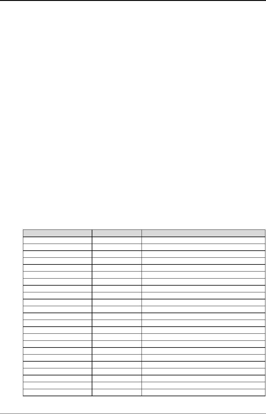
Programmer's Guide PcOS Series 150 Control Codes
EPOS Codes
12/14/99 Rev G Page 69
EPOS Codes
This section lists the EPOS codes that are supported by the Series 150 Printer. Ithaca Peripherals has
no control over how Epson extends or changes these control codes. Ithaca Peripherals makes no
guarantees as to the operation of its printer when it replaces an Epson printer. The EPOS emulation is
intended to make it as easy as possible to replace an Epson printer with an Ithaca Series 150 Printer.
The following section lists the EPOS commands that are processed. They are as close as possible to
Epson printers. The user must remember that the Series 150 Printer is not designed as a drop-in
replacement for an Epson printer. The Series 150 Printer is designed to bring new and unique
features and functionalities to a POS receipt/validation printer.
Real-time Status
The Series 150 Printer is available in serial and parallel versions. When Epson supports parallel
operation, the company redefines some of the standard IEEE 1284 interface signals to be special
status lines. The Series 150 Printer does not alter the IEEE 1284 standard. If an application
requires real-time status from the printer, the IEEE 1284 bidirectional protocol must be used.
The Series 150 Printer supports real-time status. The EPOS real-time status commands [DLE]
[ENQ] and [DLE] [EOT] are processed by the printer. The printer, however, does not support all
the response bit fields. See the descriptions below.
EPOS Command Summary
Please refer to the Epson ESC/POS Information Manual for field definitions.
The following is a list of the EPOS commands that are supported.
Command Comment Description
[BEL] Extension Activate sound buzzer.
[VT] Extension Set vertical tabs.
[LF] Set line feed.
[FF] Eject form.
[HT] Extension Set horizontal tabs.
[BS] Extension
[CR] Set carriage returns.
[CAN] Not the same Cancel print.
[ESC] [BEL] Extension Activate sound buzzer.
[ESC] SI Extension Set 24 cpi.
[ESC] [SP] <n> Set right-side character spacing.
[ESC] ! <n> Select print modes.
[ESC] $ <nL> <nH>Set absolute print position.
[ESC] % <n> Not implemented Select or cancel the user-defined character set.
[ESC] & ... Not implemented Define user-defined characters.
[ESC] * <m> <n>1 <n>2 Extension Select single-density bit image mode.
[ESC] - <n> Turn underline mode ON/OFF.
[ESC] 0 Set eight lines per inch spacing.
[ESC] 1 Set 7/72-inch spacing.
[ESC] 2 Set 6 lines per inch spacing.
[ESC] 3 <n> Set line spacing.
[ESC] 4 Extension Set italic mode set.
[ESC] 5 Extension Set italic mode reset.
Control Codes PcOS Series 150 Programmer's Guide
EPOS Codes
Page 70 Rev G12/14/99
[ESC] < Return home (not necessary with the Series
150 printer).
[ESC] = Not the same Select peripheral device (Pass through).
[ESC] ? Ignored Cancel user-defined characters.
[ESC] @ Initialize printer.
[ESC] B <n>1 <n>2 <n>3
... <n>i 0 Extension Set vertical tab stops.
[ESC] C <n> Similar Set form length.
[ESC] D <n>1 <n>2
<n>3 ... <n>i 0 Extension Set horizontal tab stops.
[ESC] E <n> Turn emphasize mode ON/OFF.
[ESC] G <n> Turn double-strike mode ON/OFF.
[ESC] J <n> Print and feed.
[ESC] K <n> Not implemented Print and reverse feed.
[ESC] M <n> Select character font.
[ESC] Q <n> Set right margin in characters.
[ESC] R <n> Select International Character Set.
[ESC] U <n> Turn unidirectional mode ON/OFF.
[ESC] V <n> Similar Turn 90° clockwise mode ON/OFF.
[ESC] [ <m> <n> Select code page/print features (same as
normal mode).
[ESC] \ <nL> <nH>Set relative print position.
[ESC] ^ ... Set Epson 9-pin bit image.
[ESC] a <n> Set left, center, or right justify.
[ESC] b <n> Print bar code (same as normal mode).
[ESC] c <n> Similar Select station. See description below.
[ESC] d <n> Feed <n> lines.
[ESC] e <n> Not implemented Print and reverse feed.
[ESC] f <t1> <t2> Similar Set wait time. See description below.
[ESC] I Set full cut.
[ESC] l <n> Set left margin in characters.
[ESC] m Set partial cut.
[ESC] p <m> <t1> <t2> Similar Generate pulse. See description below.
[ESC] q Release form.
[ESC] t <n> Select Character Code Table (may vary from
Epson Select Code).
[ESC] u <n> Return status of cash drawer (Serial and IEEE
1284 only).
[ESC] v Extension Return null byte to host.
[ESC] x <n> Extension Set print font (same as Normal [ESC] I <n>).
[ESC] { <n> Turn upside down print ON/OFF.
[ESC] ~ <n> Extension Test mode diagnostic commands.
[GS] ! Select character size.
[GS] I <n> Transmit specified ID (different than Epson).
[GS] L ... Set left margin in 1/160 inch.
[GS] W ... Select printable area in 1/160 inch.
[GS] h <n> Extension Set bar code height.
[GS] k <m> ... <0> Extension Print bar code.

Programmer's Guide PcOS Series 150 Control Codes
EPOS Deviations
12/14/99 Rev G Page 71
EPOS Deviations
There are several important differences between the Series 150 and EPSON printers. The closest
EPSON printer to the Series 150 is the TM-U325. An application that was written for the
EPSON printer may require some modification to use the Series 150.
Command Descriptions
Function Activate buzzer
ASCII [BEL] or [ESC] [BEL]
Description This command activates the sound buzzer.
Note: This command only functions if the internal buzzer option was
installed at the factory.
Function Eject form
ASCII [FF]
Description The Series 150 Printer does not support page mode. The printer will
eject a form.
Function Cancel print data
ASCII [CAN]
Description The Series 150 Printer uses [CAN] to clear the printer line buffer.
Function Return home
ASCII [ESC] <
Description The Series 150 Printer does not need this command. The Series 150
Printer never loses track of the print head. The affect of this command
is to set the next print line to print from left to right.
Function Select peripheral device
ASCII [ESC] = <n>
Description The Series 150 Printer does not support the Epson Pole Display. This
command provides print suppress and data pass through functions.
Where Bit 0 Printer select
Bit 1 Pass through
Bits 2-7 Undefined
Function Set form length
ASCII [ESC] C <n>
Description The Series 150 Printer uses this command to set the form length.

Control Codes PcOS Series 150 Programmer's Guide
EPOS Deviations
Page 72 Rev G12/14/99
Function Set print direction
ASCII [ESC] T <n>
Description The Series 150 Printer does not implement page mode. This command
uses the normal rotated print format procedures. See [ESC] r <n> in
normal mode.
Note: EPOS reverses Modes 1 and 3.
Function Print graphics
ASCII [ESC] * <m> <n>1 <n>2
Description The Series 150 Printer defines the extended graphic modes. Mode 4 is
normally 80 dpi. The Series 150 Printer does not support 80 dpi. If
Mode 4 is selected, 72 dpi will be used.
Print n1 + 256 * n2 bytes of graphics where m specifies the density.
Where m 0Single-density graphics 60 dpi
1Double-density graphics 120 dpi
2Double-density half-speed graphics 120 dpi
3High-density graphics 240 dpi
4, 5 CRT II screen 72 dpi
6CRT I screen 90 dpi
7Dual plotter 144 dpi
Function Turn 90°° clockwise font ON/OFF
ASCII [ESC] V <n>
Description The Series 150 Printer uses the rotated 90° font to implement this
command. If one dot spacing is selected, ten cpi is used. If 1.5 dot
spacing is selected, eight cpi is used.
Function Select print paper
ASCII [ESC] c 0 <n>
Description The Series 150 Printer uses this command to select a print station. The
Series 150 Printer does not keep track of different settings for each
mode. If a specific print mode is required, it must be respecified.
Function Select print paper for setting
ASCII [ESC] c 1 <n>
Description The Series 150 Printer does not keep track of different settings for
each mode. If a specific print mode is required, it must be respecified.
Function Select detectors to stop printing
ASCII [ESC] c 4 <n>
Description The Series 150 Printer does not stop at the end of forms. The
application must keep track of the form length.

Programmer's Guide PcOS Series 150 Control Codes
EPOS Deviations
12/14/99 Rev G Page 73
Function Enable/disable panel buttons
ASCII [ESC] c 5 <n>
Description The Series 150 Printer does not allow the front panel to be disabled.
Function Enable/disable on-line switch
ASCII [ESC] c 6 <n>
Description The Series 150 Printer ignores this command.
Function Generate pulse
ASCII [ESC] p <m> <t1> <t2>
Description The Series 150 Printer does not allow the cash drawer pulse to be
altered under software control. The <t1> <t2> parameters are ignored.
<m> selects Drawer 1 or 2.
Function Set impact energy
ASCII [GS] E <n>
Description The Series 150 Printer allows higher impact energy in validation
modes only.
Function Set bar code height
ASCII [GS] h <n>
Description This command sets the bar code height in dot lines. The Series 150
Printer prints bar codes in eight dot passes in graphics. The height
used in EPOS is intended for thermal printers. To allow some type of
compatibility between EPOS and the Series 150 Printer, the value of
<n> is divided by 28. This allows a similar size bar code to be printed.
Note: Values less than 28 return the printer to the default values
defined by the [ESC] [EM] B command in normal mode.

Control Codes PcOS Series 150 Programmer's Guide
EPOS Deviations
Page 74 Rev G12/14/99
Function Set bar code
ASCII [GS] k <m> {information} [NUL]
Description The Series 150 Printer uses the same print functions to print EPOS bar
codes as the normal mode bar codes.
EPOS has two formats for bar codes. One is [NUL] terminated; the
other has a length field. If <m> is greater than 64, the next byte sets
the length in bytes. Only the [NUL] terminated command is supported
by the Series 150 Printer.
Where m 0UPC A Numeric (0-9) only, 11 digits maximum
1UPC E Numeric (0-9) only, 11 digits maximum
2EAN-13 Numeric (0-9) only, 12 digits maximum
3EAN-8 Numeric (0-9) only, 6 digits maximum
4Code 39 26 uppercase letters (A-Z), 10 digits (0-9)
5Interleaved 2 of 5 Numeric (0-9) only, must be even number of
digits
Note: If Code 128 is to be printed, it must be printed with the [ESC] b
<n> command as described on page 48.
Programmer's Guide PcOS Series 150 Control Codes
MICROLINE Codes
12/14/99 Rev G Page 75
MICROLINE Codes
This section lists the MICROLINE codes that are supported by the PcOS Series 150 Printer. Ithaca
Peripherals has no control over how Okidata extends or changes these control codes. Ithaca
Peripherals makes no guarantees as to the operation of its printer when it replaces an Okidata printer.
The MICROLINE emulation is intended to make it as easy as possible to replace an Okidata printer
with a Series 150 Printer.
The following section lists the MICROLINE commands that are processed. They are as close as
possible to Okidata printers. The user must remember that the Series 150 Printer is not designed as a
drop-in replacement for an Okidata printer. The PcOS Series 150 Printer is designed to bring new
and unique features and functionalities to a POS receipt/validation printer.
MICROLINE Command Summary
Please refer to the Okidata MICROLINE Information Manual for field definitions.
The following is a list of the MICROLINE commands that are supported.
Command Description
[VT] Set vertical tabs.
[LF] Set line feed.
[FF] Set form feed.
[HT] Set horizontal tab.
[BELL] Open Cash Drawer 1.
[BS] Open Cash Drawer 2.
[CR] Set carriage returns.
[CAN] Clear print buffer.
[EM] Set full cut.
[SUB] Set partial cut.
[ESC] Begin escape sequence.
[FS] Set 12 cpi.
[GS] Set 17 cpi.
[RS] Set 10 cpi.
[US] Start double-wide print.
[ESC] HT <n>1 <n>2 <n>3 ...
<n>i 0 Set horizontal tabs.
(Sets tabs at columns n1 n2 ... nk 0)
[ESC] [DC1] Set open for validation.
[ESC] [DC3] Set close for validation.
[ESC] [DC4] Select validation mode with autoform sense.
[ESC] ! / Begin italics (Utility 10/12 cpi mode only).
[ESC] ! * End italics.
[ESC] # 0 Select high speed draft (HSD) mode.
[ESC] % 5 <n> Perform fine line feed.
[ESC] % 9 <n> Set fine line spacing.
[ESC] + Open Cash Drawer 1.
[ESC] - Select unidirection print.
[ESC] 0 Select utility print mode.
[ESC] 1 Select near letter quality (NLQ) mode.
Control Codes PcOS Series 150 Programmer's Guide
MICROLINE Codes
Page 76 Rev G12/14/99
[ESC] 6 Set 6 lines per inch.
[ESC] 8 Set 8 lines per inch.
[ESC] C Start underline.
[ESC] D Stop underline.
[ESC] J Start superscript.
[ESC] M Stop superscript.
[ESC] N Start subscript.
[ESC] M Stop subscript.
[ESC] T Begin emphasized print (half speed).
[ESC] H Begin enhanced print (double pass).
[ESC] I End emphasized/enhanced print.
[ESC] K <n>1 <n>2Set single-density graphics.
n1=0..255
n2=0..3
len=n1 + 256 * n2
[ESC] L <n>1 <n>2Set double-density half-speed graphics.
n1=0..255
n2=0..3
len=n1 + 256 * n2
[ESC] Y <n>1 <n>2Set double-density full-speed graphics.
n1=0..255
n2=0..3
len=n1 + 256 * n2
[ESC] Z <n>1 <n>2Set quad-density full-speed graphics.
n1=0..255
n2=0..3
len=n1 + 256 * n2
[ESC] r <n> Set rotated print.
n=0 end
n=2 upside down
N/A Print bar code.
Interleaved 2 of 5
Code 39
Code 128
Communication Echo Mode
(Serial interface only)
[ESC] # Turn on echo mode.
[ESC] d Turn on alternate echo mode.
[ESC] “ Turn off echo mode.
[ESC] RS Turn off alternate echo mode.
Programmer's Guide PcOS Series 150 Control Codes
STAR Codes
12/14/99 Rev G Page 77
Star Codes
This section lists the Star codes that are supported by the PcOS Series 150 Printer. Ithaca Peripherals
has no control over how Star extends or changes these control codes. Ithaca Peripherals makes no
guarantees as to the operation of its printer when it replaces a Star printer. The Star emulation is
intended to make it as easy as possible to replace a Star printer with a PcOS Series 150 Printer.
The following section lists the Star commands that are processed. They are as close as possible to a
Star printer. The user must remember that the Series 150 Printer is not designed as a drop in
replacement for a Star printer. The PcOS Series 150 Printer is designed to bring new and unique
features and functionalities to a POS receipt/validation printer.
Star Command Summary
Please refer to the Star Information Manual for field definitions.
The following is a list of the Star commands that are supported.
Command Description
Control codes used in character setting
[ESC] M Select 15-cpi character size.
[ESC] P Select 12-cpi character size.
[ESC] : Select 8-cpi character size.
[SO] Select expanded character mode.
[DC4] Cancel expanded character mode.
[ESC] E Select emphasized print mode.
[ESC] F Cancel emphasized print mode.
[ESC] – 1 Select underline mode.
[ESC] – 0 Cancel underline mode.
[ESC] _ 1 Select overline mode.
[ESC] _ 0 Cancel overline mode.
[SI] Select inverted print mode.
[DC2] Cancel inverted print mode.
Control codes used in line spacing
[LF] Set line feed.
[CR] Set carriage return.
[ESC] z 1 Set 1/6-inch line feed.
[ESC] 0 Set 1/8-inch line feed.
[ESC] a <n> Feed paper n lines.
Control codes used for page layout
[FF] Set form feed.
[ESC] C <n> Set page length at n lines.
[ESC] C <0> <n> Set page length at n inches.
[VT] Set vertical tabs.
[ESC] B <n1> <n2> Set vertical tab positions.
[ESC] l <n> Set left margin.
[ESC] Q <n> Set right margin.
[HT] Set horizontal tabs.
[ESC] D <n1> <n2> Set horizontal tab positions.
Control Codes PcOS Series 150 Programmer's Guide
STAR Codes
Page 78 Rev G12/14/99
Control codes used for graphic printing
[ESC] 1 Set 7/72-inch line feed.
[ESC] A Define n/72-inch line feed.
[ESC] 2 Set n/72-inch line feed.
[ESC] J <n> Set one-time line feed of n/72-inch.
[ESC] z 0 Set 1/12-inch line feed.
[ESC] K <n1> <0> Set 8-dot single-density bit image.
[ESC] L <n1> <n2> Set 8-dot double-density bit image.
[ESC] h 1 Select vertical expanded character mode.
[ESC] h 0 Cancel vertical expanded character mode.
Control codes used for peripheral units
[BEL] Defer drive command for Peripheral Unit 1.
[EM] Set immediate drive command for Peripheral Unit 2.
[FS] Set immediate drive command for Peripheral Unit 1.
[SUB] Set immediate drive command for Peripheral Unit 2.
Other control codes
[RS] Activate sound buzzer. 11
[CAN] Cancel print data in buffer.
[ESC] U 1 Select unidirectional print mode.
[ESC] U 0 Select bidirectional print mode.
[ESC] @ Initialize printer.
[ESC] ! * End italics.
[ENQ] Perform inquiry.
[ESC] d 0 Cycle autocutter.12
[ESC] d 1 Cycle autocutter.
[ESC] W 1 Select expanded character mode.
[ESC] W 0 Cancel expanded character mode.
[ESC] y <n> Set n/144-inch line feed.
[ESC] 3 <n> Set n/216-inch line feed.
11 This command only functions if the internal buzzer option was installed at the factory.
12 The printer can be equipped with either a full or partial cutter option.
Programmer's Guide PcOS Series 150 Control Codes
NCR2567 Codes
12/14/99 Rev G Page 79
NCR2567 Codes
This section lists the NCR codes that are supported by the PcOS Series 150 Printer. Ithaca Peripherals
has no control over how NCR extends or changes these control codes. Ithaca Peripherals makes no
guarantees as to the operation of its printer when it replaces an NCR printer. The NCR emulation is
intended to make it as easy as possible to replace an NCR printer with a Series 150 Printer.
The following section lists the NCR commands that are processed. They are as close as possible to
NCR printers. The user must remember that the Series 150 Printer is not designed as a drop-in
replacement for an NCR printer. The PcOS Series 150 Printer is designed to bring new and unique
features and functionalities to a POS receipt/validation printer.
NCR Command Summary
Please refer to the NCR Information Manual for field definitions. The following is a list of the
NCR commands that are supported.
Command Description
[ENQ] Send status byte to host.
[BEL] Open Cash Drawer 1.
[BS] Open Cash Drawer 1.
[LF] Set line feed.
[FF] Advance form one line.
[SO] Set one-line double-wide mode.
[SI] Cancel double-wide command.
[DLE] Clear all printer and interface functions.
[DC1] Deactivate all option drivers.
[DC2] Set one-line double-wide alternate command.
[DC3] Cancel double-wide alternate command.
[DC4] n Set paper feed n lines.
[NAK] n Feed n dot rows after each print line.
[SYN] n Set number of dot rows fed after each print line.
[ETB] Print buffer contents; advance one line.
[CAN] Perform validation open assembly.
[EM] Perform knife cut.
[SUB] Perform knife cut.
[GS] Close platen when form is present.
[RS] Close platen when form is present.
Control Codes PcOS Series 150 Programmer's Guide
TELPAR Codes
Page 80 Rev G12/14/99
Telpar Codes
This section list the Telpar codes that are supported by the PcOS Series 150 Printer. The Telpar
emulation is intended to make it as easy as possible to replace a Series 50 Printer with a Series 150.
Telpar Command Summary
The following is a list of the Telpar commands that are supported.
Command Description
[CR] Print and carriage return.
[LF] Print and line feed.
[ESC] [LF] <n> Feed <n> number of lines.
[FF] Advance to top of form.
[CAN] Clear buffer; restore defaults.
[ESC] 0 <n> Set page length in lines.
[ESC] 3 <n> Set extra dot row feeds per line.
ESC VT <n> Feed <n> number of dot rows.
[ESC] @ Reset printer.
[SO] Set double-wide print.
[SI] Cancel double-wide print.
[BEL] Open Cash Drawer 1.
[ESC] + Open Cash Drawer 1.
[ESC] ! Open Cash Drawer 1.
[ESC] [BEL] <n> Open Cash Drawer 1.
[ESC] a <n> Open Cash Drawer 1.
[ESC] c <n> Open Cash Drawer 1.
[ESC] b <n> Open Cash Drawer 2.
[ESC] d <n> Open Cash Drawer 2.
[ESC] “ <n> Open Cash Drawer 2.
[ESC] [DEL] Deactivate all option drivers.
[ESC] [DC1] Open for validation.
[ESC] [DC3] Close for validation.
[ESC] [NAK] Close for validation with autoform sense.
[ESC] [SYN] <n> Close for validation with autoform sense.
[ESC] [DC2] Cycle autocutter.
[VT] Feed to cut position.
[SOH] <n> Select multidrop printer.
[SOH] A Select printer with address, A.
[SOH] B Select printer with address, B.
[SOH] C Select printer with address, C.
[SOH] [DC3] Select all printers.

Programmer's Guide PcOS Series 150 Control Codes
Summary by Code
12/14/99 Rev G Page 81
Control Codes Summary by Code
Normal
ASCII Second
ASCII
field
Hex Code IPCL equivalent
code Description Page
[NUL] 00 Null
[ENQ] <n> 05H Set inquire status.
(Refer to command descriptions.) 62
[BS] 08H &%BS Set back space. 16
[HT] 09H &%HT Set horizontal tabs. 16
[LF] 0AH &%LF Set line feed. 15
[VT] 0BH &%VT Set vertical tabs. 20
[FF] 0CH &%FF Set form feed. 20
[CR] 0DH &%CR Set carriage return. 15
[SO] 0EH &%MW Se one-line double-wide print. 33
[SI] 0FH &%F1 Set 17 cpi. 31
[DC2] 12H &%F3 Set 10 cpi. 31
[DC4] 14H &%MN Cancel one-line double-wide print. 33
[CAN] 18H &%RP Clear print buffer. 55
[ESC] [SI] 1BH,0FH &%F4 Set 24 cpi. 31
[ESC] [DC1] 1BH,11H &%VO Open for validation. 52
[ESC] [DC3] 1BH,13H &%VC Close for validation. 52
[ESC] [DC4] 1BH,14H &%VS Select validation mode with
autoform sense. 52
[ESC] [EM] B
<n> 1BH,19H,
42H &%BH <m1>Set bar code height.
n=0 Restore defaults
n=1-9 Number of passes
(0.11” per pass)
50
[ESC] [EM] C
<n> 1BH,19H,
43H &%ZC <m1><m2>Set validation clamp delay. 53
[ESC] [EM] J
<n> 1BH,19H,
4AH &%BJ <m1><m2>Set bar code justification. 50
[ESC] [EM] V
<n> 1BH,19H,
56H &%ZV<m1><m2>Set validation time-out. 53
[ESC] # <0> 1BH,23H,
30H &%QT Begin HSD mode. 22
[ESC] $1BH,24H Copy ROM character set to RAM
character set. 28
[ESC] % G 1BH,25H,
47H &%MI Begin italics. 38
[ESC] % H 1BH,25H,
48H &%CI End italics. 38
[ESC] *
<m><n>
1 <n>2
1BH,2AH Print graphics in mode <m>. 46
[ESC] ! <n> 1BH,21H &%CS<n> Select the International Character
Set. 24
[ESC] - <n> 1BH,2DH &%CU {n=0}
&%MU {n=1} Set underline.
n=0 end
n=1 begin
36
[ESC] 01BH,30H &%ST Set 1/8-inch line space. 18
[ESC] 11BH,31H &%SG Set 7/72-inch line space. 19
[ESC] 21BH,32H Begin variable line spacing.
(This enables [ESC] A <n>). 19
[ESC] 3 <n> 1BH,33H &%SV <m1><m2>
<m3>Set variable space n/216-inch.
Where n=1..255 defines the feed
used by line feed.
18
Control Codes PcOS Series 150 Programmer's Guide
Summary by Code
Page 82 Rev G12/14/99
[ESC] 41BH,34H &%TF Set top of form. 20
[ESC] 5 <n> 1BH,35H &%CA {n=0}
&%MA {n=1} Set auto line feed.
n=0 end
n=1 begin
21
[ESC] 81BH,38H &%PF Disable paper error sensor. 51
[ESC] 91BH,39H &%PO Enable paper error sensor. 51
[ESC] :1BH,3AH &%F2 Set 12 cpi. 31
[ESC] < <n> 1BH,3CH &%PT Set print suppress and pass
through. 57
[ESC] =<n1>
<n2>
<start
code>
<data>
1BH,3DH Download character font image. 28
[ESC] > <n> 1BH,3EH Enable custom character set.
n=0 Off
n=1 On
16
[ESC] ?
<m><n> 1BH,3FH Reassign graphic mode. 46
[ESC] A <n> 1BH,41H Set variable line spacing to n/72.
Where n=1..85 is enabled by
[ESC] 2.
19
[ESC] B <n1>
<n2><n3>
...<ni>
<0>
1BH,42H Set vertical tab stops. 20
[ESC] C <n> 1BH,43H &%SL <m1><m2>Set form length in lines. 21
[ESC] C [NUL]
<n> 1BH,43H &%SI <m1><m2>Set form length in inches. 21
[ESC] D<n1>
<n2><n3>
..<ni><0>
1BH,44H Set horizontal tab stops. 16
[ESC] E1BH,45H &%MM Begin emphasized print. 37
[ESC] F1BH,46H &%CM End emphasized print. 37
[ESC] G1BH,47H &%ME Begin enhanced print. 37
[ESC] H1BH,48H &%CE End enhanced print. 37
[ESC] I <n> 1BH,49H &%QT {n=0}
&%QU {n=1}
&%QL {n=2}
&%QS {n=3}
Select print mode.
n=0 High Speed Draft
n=1 Utility
n=2 NLQ Courier
n=3 NLQ Sans Serif
22
[ESC] J <n> 1BH,4AH &%FM
<m1><m2><m3>Do a fine line feed. 18
[ESC] K <n>1
<n>21BH,4BH Set single-density graphics (60h x
72 v dpi). 45
[ESC] L <n>1
<n>21BH,4CH Set double-density half-speed
graphics (120 h x 72 v dpi) 45
[ESC] P <n> 1BH,50H &%RF {n=1}
&%RI {n=2}
&%RN {n=0}
Set rotated font.
n=0 normal
n=1 rotated 90°
n=2 rotated 270°
[ESC] R1BH,52H &%HV Reset horizontal and vertical tab
stops. 17
[ESC] S <n> 1BH,53H &%SB {n=1}
&%SP {n=0} Select superscript/subscript.
n=0 superscript
n=1 subscript
38
[ESC] T1BH,54H &%SE End superscript/subscript. 38
Programmer's Guide PcOS Series 150 Control Codes
Summary by Code
12/14/99 Rev G Page 83
[ESC] U <n> 1BH,55H &%GU {n=1}
&%GB {n=0} Select bidirectional/unidirectional
print.
n=0 bidirectional
n=1 unidirectional
47
[ESC] V <n> 1BH,56H Set intercharacter spacing. 32
[ESC] W <n> 1BH,57H &%FS {n=0}
&%FD {n=1}
&%FH {n=3}
Set multiline double-wide double-
high sequence.
n=0 end all
n=1 begin double-wide
n=2 double high
n=3 both
34
[ESC] X
<n1><n2>1BH,58H Set left and right margins.
n1=left
n2=right
[ESC] Y <n>1
<n>21BH,59H Set double-density full-speed
graphics (120 h x 72 v dpi). 45
[ESC] Z <n>1
<n>21BH,5AH Set quad-density full-speed
graphics (240 h x 72 v dpi). 45
[ESC] [ @ ... 1BH,5BH,
40H &%DH
&%SH Set print style.
(See command description.) 34
[ESC] [ P <n> 1BH,5BH,
50H &%F1-7 Set character pitch. 32
[ESC] [ T <n> 1BH,5BH,
54H &%CP<m1><m2>
<m3><m4>Select character code page. 26
[ESC] ]1BH,5DH &%LR Set reverse line feed. 21
[ESC] ^ <n> 1BH,5EH &%CC
<m1><m2><m3>Print control character. 27
[ESC] _ <n> 1BH,5FH &%CO {n=0}
&%MO {n=1} Enable overscore.
n=0 end
n=1 begin
36
[ESC] a <n> 1BH,61H &%JL {n=0}
&%JC {n=1}
&%JR {n=2}
Set justification.
n=0 left
n=1 center
n=2 right
17
[ESC] b <n> ...
[ETX] 1BH,62H &%25 {n=0}
&%39 {n=1}
&%12 {n=2}
&%UP {n=3}
&%EA {n=4}
&%UE {n=5}
&%E8 {n=6}
&%93 {n=7}
&%HB {n=10}
Print bar code.
n=0 Interleave 2 of 5
n=1 Code 39
n=2 Code 128
n=3 UPC A
n=4 EAN-13
n=5 UPC-E
n=6 EAN-8
n=7 Code 93
n=10 Hollerith
48
[ESC] d <n> 1BH,64H &%FL<m1><m2>Feed <n> lines at the current
spacing. 19
[ESC] q <n> 1BH,71H Set query marker.
[ESC] r <n> 1BH,72H &%R0 {n=0}
&%R1 {n=1}
&%R2 {n=2}
&%R3 {n=3}
&%R5 {n=5}
&%R7 {n=7}
Set rotated print.
n=0 end
n=1 rotate by 90°
n=2 rotate left 180°
n=3 rotate by 270°
n=5 rotate by 90° with formatting
n=7 rotate by 270° with formatting
41
[ESC] s <n> 1BH,73H &%RL<m1><m2>
<m3>Set rotated print line length. 43

Control Codes PcOS Series 150 Programmer's Guide
Summary by Code
Page 84 Rev G12/14/99
[ESC] u<n1>
<m1>
<n2>
<m2>...
<ni><mI>
<0>
1BH,75H Set rotated print line spacing. 44
[ESC] v1BH,76H &%FC Cut Activate cutter 58
[ESC] w <n> 1BH,77H Enable dynamic response. 58
[ESC] x <n> 1BH,78H &%D1 {n=1}
&%D2 {n=2} Open cash drawer.
n=1 Cash Drawer 1
n=2 Cash Drawer 2
55
[ESC] y <n> 1BH,79H &%Y0-8 Control diagnostics and extended
features. (See description.) 57
[ESC] ~ <n> 1BH,7EH Set extended diagnostics. 68
Programmer's Guide PcOS Series 150 Control Codes
Summary by Function
12/14/99 Rev G Page 85
Control Codes Summary by Function
Normal
ASCII Second
ASCII
field
Hex Code IPCL equivalent
code Description Page
Print/paper motion
[CR] 0DH &%CR Set carriage return. 15
Vertical motion
[LF] 0AH &%LF Set line feed. 15
[VT] 0BH &%VT Set vertical tabs. 20
[FF] 0CH &%FF Set form feed. 20
[ESC] 01BH,30H &%ST Set 1/8-inch line space. 18
[ESC] 11BH,31H &%SG Set 7/72-inch line space. 19
[ESC] 21BH,32H Begin variable line spacing.
(Enable [ESC] A n). 19
[ESC] 3 <n> 1BH,33H &%SV
<m1><m2><m3>Set fine line space n/216 inch where
n=1..255 defines the feed used by
line feed.
18
[ESC] 41BH,34H &%ST Set top of form. 20
[ESC] 5 <n> 1BH,35H &%CA {n=0}
&%MA {n=1} Set auto line feed.
n=0 end
n=1 begin
21
[ESC] A <n> 1BH,41H Set variable line spacing n/72 where
n=1..85 is enabled by [ESC] 2. 19
[ESC] B
<n>1<n>2
<n>3...
<n>k <0>
1BH,42H Set vertical tabs at lines n1 n2...
nk 0. 20
[ESC] C <n> 1BH,43H &% Set form length in lines or inches. 21
[ESC] J <n> 1BH,4AH &%FM
<m1><m2><m3>Do a fine line feed n/216 inch.
n=0 no line feed
n=1..255
18
[ESC] R1BH,52H &%HV Reset horizontal and vertical tabs to
defaults. 17
[ESC] ]1BH,5DH &%LR Reverse line feed. 21
[ESC] d <n> 1BH,64H &%FL
<m1><m2>Feed <n> lines at the current
spacing. 19
Horizontal motion
[HT] 09H &%HT Set horizontal tabs. 16
[ESC] D
<n>1<n>2
<n>3...
<n>k <0>
1BH,44H Set horizontal tabs at columns n1 n2
... nk 0. The maximum value of n
depends on the station selected.
16
[ESC] R1BH,52H &%HV Reset horizontal and vertical tabs to
defaults. 17
[ESC] V <n> 1BH,56H Set intercharacter spacing. 32
[ESC] X
<n1><n2>1BH,58H Set left and right margins.
n1=left in characters
n2=right in characters
[ESC] a <n> 1BH,61H &%JR
&%JC
&%JL
Set justification.
n=0 left
n=1 center
n=2 right
n=4 180° right
n=5 180° center
n=6 180° left
180° mode not available in IPCL.
17
Control Codes PcOS Series 150 Programmer's Guide
Summary by Function
Page 86 Rev G12/14/99
[ESC] U <n> 1BH,55H &%GU {n=1}
&%GB {n=0} Select bidirectional/unidirectional
mode.
n=0 bidirectional
n=1 unidirectional
47
[ESC] # 0 1BH,23H,
30H &%QT Set Normal Print Mode. (HSD is
normal.) 22
[ESC] E1BH,45H &%MM Begin emphasized print
(half-speed). 37
[ESC] F1BH,46H &%CM End emphasized print. 37
[ESC] G1BH,47H &%ME Begin enhanced print (double pass). 37
[ESC] H1BH,48H &%CE End enhanced print. 37
[ESC] I <n> 1BH,49H &%QT {n=0}
&%QU {n=1}
&%QS {n=2}
&%QL {n=3}
Select print mode.
n=0 High Speed Draft
n=1 Utility
n=2 NLQ Sans-Serif
n=3 NLQ Courier
22
[ESC] [ @ ... 1BH,5BH,
40H Set print style. (See command
description.) 34
International Character Sets
[ESC] ! <n> 1BH,21H &%CS<n> Select International Character Set. 24
[ESC] [ T <n> 1BH,5BH,
54H &%CP
<m1><m2><m3>
<m4>
Set character set by code page. 26
Custom characters
[ESC] $1BH,24H Copy ROM character set to RAM
character set. 28
[ESC] =<n>1
<n>2
<start
code>
<data>
1BH,3DH Download character font image. 28
[ESC] > <n> 1BH,3EH Set custom character.
n=0 OFF
n=1 ON
28
Character pitch
[DC2] 12H &%F3 Set 10 cpi. 31
[ESC] :1BH,3AH &%F2 Set 12 cpi. 31
[SI] 0FH &%F1 Set 17 cpi. 31
[ESC] [SI] 1BH, 0FH &%F4 Set 24 cpi. 31
[ESC] [ P <n> 1BH,5BH,
50H &%F1-7 Set character pitch. 32
Character attributes
[SO]4 0EH &%MW Set one-line double-wide mode. 33
[DC4] 14H &%MN Cancel one-line double-wide mode. 33
[ESC] > <n> 1BH,3EH Set custom character.
n=0 OFF
n=1 ON
28
[ESC] % G 1BH,25H,
47H &%MI Begin italics. 38
[ESC] % H 1BH,25H,
48H &%CI End italics. 38
[ESC] - <n> 1BH,2DH &%CU {n=0}
&%MU {n=1} Set underline.
n=0 end
n=1 begin
36
[ESC] S <n> 1BH,53H &%SB {n=1}
&%SP {n=0} Select superscript/subscript.
n=0 superscript
n=1 subscript
38
[ESC] T1BH,54H &%SE End superscript/subscript. 38

Programmer's Guide PcOS Series 150 Control Codes
Summary by Function
12/14/99 Rev G Page 87
[ESC] W <n> 1BH,57H &%FS {n=0}
&%FD {n=1}
&%FH {n=3}
Set multiline double-wide double-
high sequence.
n=0 end all
n=1 double-wide
n=2 double-high
n=3 both
34
[ESC] _ <n> 1BH,5FH &%CO {n=0}
&%MO {n=1} Set overscore.
n=0 end
n=1 begin
36
Rotated print
[ESC] P <n> 1BH,50H &%RF {n=1}
&%RI {n=2}
&%RN {n=0}
Rotate font.
n=0 normal
n=1 rotated 90°
n=2 rotated 270°
23
[ESC] r <n> 1BH,72H &%R0 {n=0}
&%R1 {n=1}
&%R2 {n=2}
&%R3 {n=3}
Rotate print.
n=0 end
n=1 rotate by 90°
n=2 rotate left 180°
n=3 rotate by 270°
41
[ESC] s <n> 1BH,73H &%RL
<m1><m2><m3>Set rotated print line length.
n=1..128 (Default 80) 43
[ESC] u <n>1
<m>1
<n>2
<m>2 ...
<n>k <0>
1BH,75H &%RS Set rotated print line spacing.
nk=0 End where n=line and
m=dots from last line.
Note: All lines not specified are set
to 1 dot.
44
Graphics
[ESC] * <m>
<n>1
<n>2
1BH,2AH Print Epson 9-pin graphics in mode
<m>. 46
[ESC] ?
<m><n> 1BH,3FH Reassign graphic mode. 46
[ESC] K <n>1
<n>21BH,4BH Set single-density graphics.
n1=0..255
n2=0..3
len=n1 +256*n2
45
[ESC] L <n>1
<n>21BH,4CH Set double-density half-speed
graphics.
n1=0..255
n2=0..3
len=n1 + 256*n2
45
[ESC] Y <n>1
<n>21BH,59H Set double-density full-speed
graphics.
n1=0..255
n2=0..3
len=n1 +256 * n2
45
[ESC] Z <n>1
<n>21BH,5AH Set quad-density full-speed
graphics.
n1=0..255
n2=0..3
len=n1 +256 * n2
45
[ESC] U <n> 1BH,55H &%GU {n=1}
&%GB {n=0} Select bidirectional/unidirectional
mode.
n=0 bidirectional
n=1 unidirectional
47
Control Codes PcOS Series 150 Programmer's Guide
Summary by Function
Page 88 Rev G12/14/99
Bar codes
[ESC] b <n> ...
[ETX] 1BH,62H &%25 {n=0}
&%39 {n=1}
&%12 {n=2}
&%UP {n=3}
&%EA {n=4}
&%EA {n=5}
&%EA {n=6}
&%93 {n=7}
&%HB {n=10}
Print bar codes.
n=0 Interleave 2 of 5
n=1 Code 39
n=2 Code 128
n=3 UPC A
n=4 EAN-13
n=5 UPC E
n=6 EAN-8
n=7 Code 93
n=10 Hollerith
48
[ESC] [EM] B
<n> 1BH,19H,
42H &%BH <m1>Set bar code height.
n=0 restore defaults
n=1-9 number of passes
(0.11” per pass)
50
[ESC] [EM] J
<n> 1BH,19H,
4AH &%BJ <m1><m2>Set bar code justification. 50
Validation control
[ESC] [DC1] 1BH,11H &%VO Open for validation. 52
[ESC] [DC3] 1BH,13H &%VC Close for validation. 52
[ESC] [DC4] 1BH,14H &%VS Select validation mode with auto
form sense. 52
[ESC] [EM] C
<n> 1BH,19H,
43H &%ZC <m1><m2>Set validation clamp delay. 53
[ESC] [EM] V
<n> 1BH,19H,
56H &%ZV <m1><m2>Set validation time-out. 53
Miscellaneous
[ENQ] <n> 05H Set inquire status.
(Refer to command descriptions.) 62
[CAN] 18H &%RP Clear print buffer. 55
[ESC] 81BH,38H &%PF Disable paper error sensing. 51
[ESC] 91BH,39H &%PO Enable paper error sensing. 51
[ESC] <1BH,3CH &%PT Set print suppress and pass
through. 57
[ESC] q<n> 1BH,71H None Set query marker. 56
[ESC] v1BH,76H &%FC Cut Activate cutter. 58
[ESC] w <n> 1BH,77H None Enable dynamic response. 58
[ESC] x <n> 1BH,78H &%D1 {n=1}
&%D2 {n=2} Open cash drawer.
n=1
n=2
55
Diagnostics
[ESC] y <n> 1BH,79H &%Y0 - 7 Control diagnostics and extended
features.
(See descriptions on page 57.)
57
[ESC] ~ <n> 1BH,7EH Set diagnostics commands enabled
by [ESC]y<8>. (See command
description for <n>.)
68

Programmer's Guide PcOS Series 150 Operator Panel Controls
12/14/99 Rev G Page 89
Chapter 6:
Operator Panel Controls
Push Buttons - Momentary Switches
The FEED key advances the receipt and journal paper.
The RELEASE key opens and closes the validation clamp. It cycles through open and close mode.
The RESUME key restarts the printer after a failure has been cleared.
Indicators
There are three indicators. They are READY, ALARM, and POWER. The printer can be in any of
the following states.
STATE READY ALARM POWER
(Green (Red (Green
Indicator) Indicator) Indicator)
Ready (The printer is ready to receive data and print.) On Off On
Not ready Off Off On
Off-line
Ready but waiting for a form Flash Off On
Out of paper Off On On
Menu mode Flash Off Flash
Test mode Flash Off On
Printer fault Off Flash On
Printer failure Off Off Off
Watchdog fault (The printer resets.)

Operator Panel Controls PcOS Series 150 Programmer's Guide
Page 90 Rev G12/14/99
Fault Indicators
If the printer indicates printer fault, the error is not recoverable. The printer must be restarted and
may lose information. To aid in printer troubleshooting, the RESUME key will activate an extended
diagnostic indication. This will blink the status indicator a number of times. The number of blinks
indicates the fault. The fault list follows.
Faults while in operation:
1Motor move time-out
2Motor move retry fault
3Motor move fault (moved in wrong direction)
4Space motor locked
5Motor homing fault
6Motor acceleration fault
7Printing fault
8Fault while centering
9Forms compensation fault
Faults during Level 0 diagnostics:
10 ROM check-sum failure
11 RAM failure
12 Configuration EEPROM failure
13 Processor test fault
14 EEPROM check-sum failure
Faults that can happen at anytime:
15 Firmware control fault (loss of program control)
16 Cutter option fault
After the fault code is displayed, the printer can be restarted by pressing the RESUME and RELEASE
keys simultaneously.
If the EEPROM check-sum fault occurs (Fault Code 14), the EEPROM can be set to default by
pressing the RESUME and LF keys simultaneously. The printer will be functional but must be
reconfigured. This procedure is only to allow reconfiguration and not to recover printer function in
the field.
If the indication is printer failure, the printer controller is not running and is being held in reset. If
this failure occurs, the printer is not functional and should be serviced.
If the printer appears to go through a power cycle by itself, the hardware watchdog has detected a
fault. This fault is generally a hardware failure or an external interference. If the fault is hardware,
the printer will continue to cycle through its diagnostics and then reset. If this happens, the printer
must be serviced. If the fault is caused by external interference like electrostatic discharge (ESD), the
printer will generally recover by itself. (Note: The parallel port INIT pin causes a soft reset.)

Programmer's Guide PcOS Series 150 Product Self-tests
12/14/99 Rev G Page 91
Chapter 7:
Product Self-tests
The Series 150 Printer contains several levels of self-test features. At power on, the printer always runs
Level 0 diagnostics which check the printer’s operation. After Level 0 diagnostics, the printer checks the
keypad and enters normal operation or extended tests.
Level 0 Diagnostics
Level 0 diagnostics always run at power up. They perform the following tasks.
Test READY ALARM POWER
(Green (Red (Green
Indicator) Indicator) Indicator)
Reset On On On
CPU Test and ROM Test Off Off On
External RAM Test On Off On
If any of these tests fail, the printer will fault, and an error will be displayed.
Extended Diagnostics
Extended diagnostics are entered after Level 0 diagnostics and allow one of four modes to be entered.
The four modes are self-test, hex-dump, configuration, and remote configuration. In self-test mode,
the various modes of the printer can be tested. Hex-dump mode causes the printer to print the hex
value of any print information sent. Configuration mode allows various configuration parameters to
be adjusted, and remote configuration mode allows CFG150 to configure the printer.
Self test
Self test is entered by pressing and holding the RESUME key at power up. (As soon as the
printer starts to print, the key should be released). The printer will print the software revision
information and instructions for using this mode. The FEED key will feed paper. The RELEASE
key will select a test, and the RESUME key will start the test.
There are currently six tests in the test suite. The tests are described below.
1. The Receipt Test prints a sample receipt.
2. The Validation Test performs a sample validation.
3. The Self Test provides a test of a number of the printer’s print capabilities.
4. The Mechanical Test Mode allows the forms compensation mechanism to be tested.
5. The Rolling ASCII Test allows continuous print on the printer. (It tests reliability and ribbon
life).
6. The Burn In Test is used as part of the production process to assure that the printer functions
correctly and to provide an initial burn in.

Hex-dump Mode PcOS Series 150 Programmer's Guide
Page 92 Rev G12/14/99
Chapter 8:
Hex-dump Mode
Hex-dump mode is entered by pressing and holding the RESUME and RELEASE keys at power up. This
mode is used to diagnose communication problems with the printer. As information is received by the
printer, the information is converted to a HEX/ASCII format and printed. No translation is made which
means that no commands are interpreted. All information is converted to HEX/ASCII and printed on the
receipt tape. If a carriage return is sent to the printer, it will be translated to 0D in the HEX field and "."
in the ASCII field.
The format is as follows:
54 68 69 73 20 69 73 20 This is
61 20 74 65 73 74 0D 0A a test..
There are several indications of printer and host communication problems that can be deduced from this
test. If the printer is printing all 40 "@" symbols, the parity or the number of bits is wrong. If the printer
is printing some Hex 40 "@" symbols when it should be printing other characters, either the parity, baud
rate, or the bit length setting is wrong. If the printer prints incorrect characters (like Hex C1 instead of
Hex 41 "A"), it is set for 8-bit data, and the host is set for 7-bit. In most cases, the print problem can be
traced to the host and printer not being configured in the same way.

Programmer's Guide PcOS Series 150 Configuration Mode
12/14/99 Rev G Page 93
Chapter 9:
Configuration Mode
Initial Power ON
The initial power cycle of a Series 150 diagnostic will find that the EEPROM is not valid. Remaining
in Level 0 diagnostics for about ten seconds will indicate this. During this time, the EEPROM is
initialized and a default configuration loaded. The default will allow manual or remote configuration.
It is unlikely to be the desired configuration.
Manual Configuration13
This mode is entered by pressing and holding the FEED and RESUME keys at power up. (As soon as
the printer starts to print, the keys should be released). The printer will print the software revision
information and instructions for using manual configuration.
• The RESUME key will select the next group.
• The RELEASE key will select the next item.
• The RELEASE and RESUME keys together will select the next option.
• The RESUME and FEED keys together will print a list of all the settings.
• The FEED key will feed paper.
Once in configuration mode, the item to be changed should be selected with the RELEASE and
RESUME keys. The item is changed when the RESUME and RELEASE keys are pressed together. It
should be noted that in test mode keys operate when released and not when they are pressed. This
allows for multiple key depressions to be recognized.
When the proper configuration is selected, it should be verified by printing the complete
configuration. The save configuration option should then be changed from “No” to “Yes.” The next
group selected will save the configuration and enter normal operation.
Enable Remote Configuration
Remote configuration mode allows a remote host to set up, display configuration information, and test
a Series 150 Printer. This mode is designed to be operated by the CFG150 program running on a
personal computer.
To enable remote configuration, connect a personal computer through the serial or parallel port on
the Series 150 Printer. Load the configuration program into the personal computer, and enter
configuration mode. Power on the printer, and hold the FEED and RELEASE keys down. After Level
0 diagnostics, the printer will enter CFG150 Mode. Refer to the CFG90/150 User’s Guide (PN 100-
01082) for more information.
13 Manual configuration may be locked by remote configuration. If this is the case, the only way to alter
the configuration is by remote CFG150 configuration.
Configuration Mode PcOS Series 150 Programmer's Guide
Page 94 Rev G12/14/99
Feature Configuration
The Series 150 Printer has many configurable features. The following section discusses these features
and the possible configurations. An operator can configure most of the features by manipulating the
key panel in configuration mode. This method is termed manual configuration.
Features can be configured by the CFG150 program. This program runs on most standard personal
computers. Refer to the CFG90/150 User’s Guide (PN 100-01082) for a description on how CFG
operates. This section lists the configurations that can be set by CFG150.
Configuration features are grouped into six categories. Each category has several features, and each
feature has one or more selections. The following table lists all the groups, features, and selections.
The default factory settings are indicated with an “*”14 which may not be the same as initial power up
configuration.
General Recommendation
Emulation
Mode The Series 150 Printer supports several emulation modes,
Normal (IBM), EPOS (Epson), MICROLINE (Okidata), Star
(Star), NCR2567 (NCR), or Telpar.
Normal
EPOS
MICROLINE
Star
NCR2567
Telpar
Configuration The Series 150 Printer supports several emulations and
custom configurations. These options are intended to support
those special modes.
Normal
Option 1
Epson Emulation: [ESC] 3 <n> sets line spacing. The default
resolution is n/144. With this option, the resolution will be
n/360.
Epson Emulation: [ESC] ! <n> sets print mode. The default is
normally 17 characters per inch (cpi). With this option, the
cpi is 20.
Microline Emulation: [CAN] will return the printer to default.
NCR2567 Emulation: sets the printer to six-line validation.
Option 2
Microline Emulation: enables [SOH] [DC1] (select code) and
[SOH] [DC3] (deselect code).
NCR2567 Emulation: allows the printer to select extended
IBM Code.
Option 3
Option 4
Microline Emulation: enables [SOH] [DC3] (select code) and
[SOH] [DC1] (deselect code).
Option 5
Microline Emulation: the 12 cpi command changes to 24 cpi.
Option 6
Option 7
Graphics The default print mode for graphics can be set to bidirectional
for fastest print or unidirectional for the best print quality.
Bidirectional
14 The factory defaults can be altered by customer order.
Programmer's Guide PcOS Series 150 Configuration Mode
12/14/99 Rev G Page 95
Unidirectional
General Recommendation
Receive
Buffer The input receive buffer can be configured to various sizes.
The optimal size is dependent on the application. The options
are from 256 to 6144 bytes. To provide tight control of the
printer, one-line mode is also available. In one-line mode, the
printer goes busy after each [CR] and stays busy until the
buffer is empty.
256 bytes
1024 bytes
2048 bytes
3072 bytes
4096 bytes
5120 bytes
6144 bytes
1-line mode
Print
Alignment The line to line print registration of the printer is adjustable.
This registration is important in graphics and rotated print and
is set at the factory. However, if the printer has been serviced,
this value may need to be adjusted. The adjustment can be
from -5 to +5. To aid in setting this adjustment, the printer will
print an alignment chart along with the adjustment.
Adjust from 0 to 9 3
Impact
Energy To allow the printer to print better on multipart forms, the
impact energy supplied to the print head can be increased. In
high impact mode, the print speed is decreased by about 15
percent. The high impact is only effective in validation mode.
Normal
Heavy validation
Form Sense
Wait The amount of time the printer waits after a form is sensed
and before action is taken is adjustable. This is the form
sense wait time.
It can be adjusted from 0 to 750 milliseconds. 250 ms
Validation
Time-out The printer can be configured to return to receipt mode after a
slip or validation command is issued. The time-out is
adjustable from off (waits forever) to 15 minutes. The slip and
validation modes can be individually configured.
Off
1 to 15 minutes
Cash Drawer
Time The amount of time the cash drawer is energized is
adjustable from 25 to 250 milliseconds. The value will be
dependent on the cash drawer being used; however, 150 ms
works with most drawers.
25 to 250 milliseconds (50 millisecond resolution) 150 ms
Reset Inhibit The reset command can be prevented from being acted on. If
Reset Inhibit is set to on, the command will have no effect.
(This does not effect the parallel port INIT signal.)
Off
On
Print
Suppress and
Pass through
The print suppress feature can be off, on, or pass (pass
through). This feature will determine the operation of the print
suppress command. If print suppress is set to off, the
command will be ignored. If on, the command will be active.
If pass is selected, the command and data pass through will
be active.
Off
Suppress
Pass through

Configuration Mode PcOS Series 150 Programmer's Guide
Page 96 Rev G12/14/99
Programmer's Guide PcOS Series 150 Configuration Mode
12/14/99 Rev G Page 97
General Recommendation
10 cpi The 10 cpi command can be prevented from being acted on.
If set to disable, the printer will ignore the 10 cpi command
(DC2).
Active
Disabled
Print Illegal
Commands No
Yes
Print Zone There are two print zone settings.
Normal (2.40 inch)
Wide (2.83 inch)
Series 50
Compatibility The Ithaca Series 50 Printer uses several commands that are
not supported by the Series 150 Printer. In some cases, these
commands have different functions in the Series 150 Printer.
If this option is set, the Series 50 commands are activated
and overlapping Series 150 commands deactivated.
Off
On
Vertical
Control
Line Spacing The line spacing can be defaulted to 6 or 8 lpi.
6 lpi
8 lpi
Auto Line
Feed An auto line feed feature can be set as a default where all
[CR]’s will have a [LF] added. If auto line feed is set to on,
this feature is activated.
Off
On
Auto Carriage
Return An auto carriage return feature can be set as a default where
all [LF]’s will have a [CR] added. If auto carriage return is set
to on, this feature is activated.
Off
On
Form Length The default form length can be set from 3 to 17 inches. This
configuration affects how the [FF] command operates.
3 to 17 inches 11
Line Feeds
Before Cut The number of line feeds before a cut operation is performed
can be set from 0 to 15 lines.
0 to 15 lines 0
Character
Print Mode The default print mode can be set to Draft, Utility, NLQ
Courier, or NLQ Sans Serif. In most cases, Draft or Utility
mode will be the default selections.
Draft
Utility
NLQ Courier
NLQ Sans Serif
Character
Pitch The default print pitch can be set to 8, 10, 12, 15, 17.1, 20, or
24 characters per inch.
8 cpi
10 cpi
12 cpi
15 cpi
17.1 cpi
20 cpi
24 cpi

Configuration Mode PcOS Series 150 Programmer's Guide
Page 98 Rev G12/14/99

Programmer's Guide PcOS Series 150 Configuration Mode
12/14/99 Rev G Page 99
General Recommendation
Font The Series 150 Printer supports 66 Language Sets. This
setting defines only the default printer mode. Any set can be
selected through software.
Language Set IBM specifies code pages differently than Epson. This is the
IBM description
IBM Code Page Translation Table
437 – USA
850 – Multilingual
865 – Norway
860 – Portugal
863 – Canada French
852 – East Europe Latin II
1018 – ECMA-94
1028 – Roman-8
861 – Icelandic-861
774 – Baltic_774
1026 – ISO Latin 4 (8859/4)
1029 – ISO Latin 6 (8859/10)
1034 – Windows Baltic
1035 – Cyrillic-Latvian
1033 – KBL-Lithuanian
1012 – Turkey
1021 – Latin 5 (Windows Turkey)
857 – Turkey_857
1008 – Greek_437
1009 – Greek_928
869 – Greek_869
1020 – Windows Greek
1011 – Greek_437 CYPRUS
862 – Hebrew NC (862)
1030 – Hebrew NC (862)
1031 – Hebrew OC
1032 – Windows Hebrew
1015 – ISO Latin 2
1019 – Windows East Europe
1014 – Polska Mazovia
895 – Kamenicky (MJK)
1024 – Hungarian CWI
1016 – Serbo Croatic I
1017 – Serbo Croatic II
1027 – Ukrainian
1072 – Bulgarian
1022 – Windows Cyrillic
855 – Cyrillic I – 855
866 – Cyrillic II – 866
1013 – Cyrillic II – 866
65 – ASCII (Unslashed 0)
67 – German
66 – British
69 – Swedish I
74 – French Canadian
72 – Dutch
76 – Swedish II
77 – Swedish III
78 – Swedish IV
79 – Turkish
Configuration Mode PcOS Series 150 Programmer's Guide
Page 100 Rev G12/14/99
80 – Swiss I
General Recommendation
81 – Swiss II
90 – Publisher
91 – Welsh
68 – French
70 – Danish
71 – Norwegian
64 – ASCII (Slashed 0)
73 – Italian
75 – Spanish
91 – Welsh
EPOS Mode
Code Page Epson specifies code pages differently than IBM. This is the
Epson description.
0 – USA
26 – Multilingual
27 – Norway
28 – Portugal
43 – Canada French
46 – East Europe Latin II-852
42 – ECMA-94
58 – Roman-8
73 – Icelandic-861
74 – Baltic_774
56 – ISO Latin 4(8859/4)
67 – ISO Latin 6 (8859/10)
68 – Windows Baltic
69 – Cyrillic-Latvian
63 – KBL-Lithuanian
29 – Turkey
51 – Latin 5 (Windows Turkey)
57 – Turkey_857
38 – Greek_437
39 – Greek_928
47 – Greek_869
50 – Windows Greek
41 – Greek_437 CYPRUS
60 – Hebrew NC (862)
61 – Hebrew OC
62 – Windows Hebrew
23 – ISO Latin 2
49 – Windows East Europe
22 – Polska Mazovia
55 – Kamenicky (MJK)
54 – Hungarian CWI
24 – Serbo Croatic I
25 – Serbo Croatic II
66 – Ukrainian
72 – Bulgarian
52 – Windows Cyrillic
44 – Cyrillic I-855
21 – Cyrillic II-866
45 – Cyrillic II-866
1 – French
2 – German
3 – British
4 – Danish I
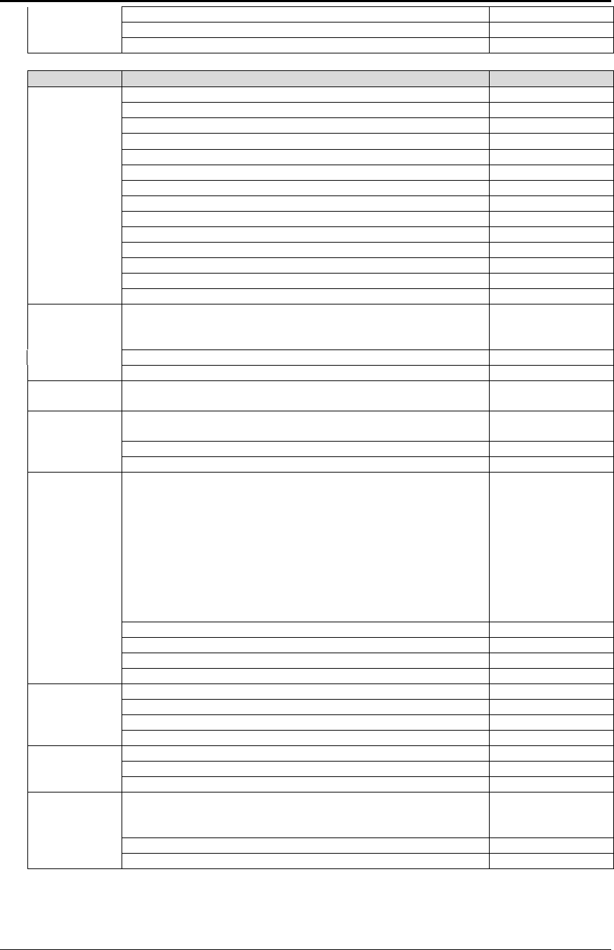
Programmer's Guide PcOS Series 150 Configuration Mode
12/14/99 Rev G Page 101
5 – Swedish I
6 – Italian
7 – Spanish I
General Recommendation
8 – Japanese
9 – Norwegian
10 – Danish II
11 – Spanish II
12 – Latin American
13 – French Canadian
14 – Dutch
15 – Swedish II
16 – Swedish III
17 – Swedish IV
18 – Turkish
19 – Swiss I
20 – Swiss II
64 – Publisher
Zero
Character The zero character can be configured to be unslashed or
slashed in all character sets except IBM 64 and 65 which
override this setting.
Unslashed
Slashed
Interface The Series 150 Printer supports either a serial or parallel
communication link.
Parallel Mode This setting should not be changed except from parallel to
IEEE 1284.
Parallel
IEEE 1284
Parallel Link
Options The parallel option features define how the strobe, busy, and
acknowledge signals operate. In normal mode, the printer
follows the standard (Centronics) parallel port conventions.
With Options 1 and 3, the acknowledge and busy signals
change at the same time. This is sometimes referred to as
Ack-after-Busy. Options 2 and 3 force busy high on the rising
edge of strobe. This is sometimes referred to as Busy-while-
Strobe timing. In all cases, the data is latched on the rising
edge of the strobe. In most cases, the normal timing mode
will give the best and most universal results.
Normal Ack-while-Busy
Option 1 Ack-after-Busy
Option 2 Ack-while-Busy
Option 3 Ack-after-Busy
Parity The serial mode parity can be set to none, odd, or even.
None
Odd
Even
Bit Data The serial bit format can be set to 8 or 7.
8
7
Protocol The flow control protocol/serial link can be set to Ready/Busy
or XON/XOFF. If XON/XOFF is selected, Ready/Busy also
functions.
Ready/Busy
XON/XOFF
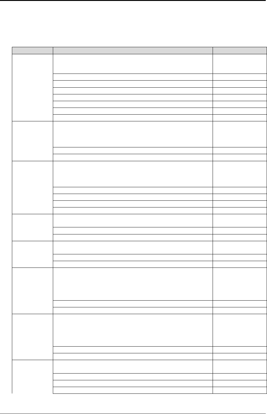
Configuration Mode PcOS Series 150 Programmer's Guide
Page 102 Rev G12/14/99
General Recommendation
Baud Rate The bit rate of the printer can be set to 19200, 9600, 4800,
2400, 1200, 600, or 300 bits per second. The same bit rate is
for send and receive.
19200 bits per second
9600 bits per second
4800 bits per second
2400 bits per second
1200 bits per second
600 bits per second
300 bits per second
SSD Signal The serial port SSD signal can be configured to provide flow
control. If SSD is active, it will toggle to false when the buffer
is full. Note: SSD flow control is only available on the optional
25-pin serial interface.
Not used
Active
DTR/RTS
Signal The serial port DTR and/or RTS signal can be configured to
provide flow control. If DTR is configured as the flow control
signal, it will toggle to false when the buffer is full, RTS will
not.
Not used
DTR flow
RTS flow
RTS and DTR flow
CTS Signal If active, a false CTS will prevent the printer from sending any
data to the host.
Not used
Active
DSR Signal If active, a false DSR signal will prevent the printer from
accepting any data.
Not used
Active
Off-line The printer can be set to active (normal operation) or buffer
full only mode. In active mode, the printer goes off-line when
it runs out of paper. In buffer full only mode, the printer only
goes off-line if a fault is detected, and the buffer full operates
normally.
Active
Buffer full only
Microsoft
Windows
Plug and Play
This option allows Windows to query the printer as to its
identity. The printer supports this in parallel and serial mode.
This option presets several of the link modes.
Serial mode RTS flow control
Parallel mode IEEE 1284
Off
On
Multidrop If set to an address, the multidrop feature will be activated at
power up.
Off
A device
B device

Programmer's Guide PcOS Series 150 Configuration Mode
12/14/99 Rev G Page 103
C device
Options
Knife This specifies that the knife is attached.
Not present
Enabled
Validation This specifies that the unit has validation.
Not present
Enabled
General Recommendation
Journal This specifies that the unit has journal take-up.
Not present
Enabled
Save
Changes This is set only in self-configuration mode to force the printer
to save changes. If this is not set to yes, any changes made
to the configuration will not be saved.
No
Yes
General Control
The Series 150 Printer supports several printer emulation modes, Normal (IBM), EPOS (Epson),
MICROLINE (OKIDATA), Star (Star), NCR2567 (NCR), and Telpar.
The default print mode for graphics can be set to bidirectional for fastest print or unidirectional
for the best print quality.
The input receive buffer can be configured to various sizes. The optimal size is dependent on the
application. The options are from 256 to 6144 bytes. To provide tight control of the printer, a
one-line mode is also available where the printer goes busy after each [CR] and stays busy until
the buffer is empty.
The line to line print registration of the printer is adjustable. This registration is important in
graphics and rotated print and is set at the factory. However, if the printer has been serviced this
value may need to be adjusted. The adjustment can range from zero to nine. To aid in setting this
adjustment, the printer will print an alignment chart.
To allow the printer to print better on multipart forms, the impact energy supplied to the print
head can be increased. In high impact mode, the print speed is decreased by about 15 percent.
High impact is only effective in validation mode.
The amount of time the printer waits after a form is sensed and before action is taken is
adjustable. This is the form sense wait time. It can be adjusted from zero to 750 milliseconds.
The default is 250 milliseconds.
The printer can be configured to return to receipt mode after a validation command is issued. The
time-out is adjustable from off (waits forever) to 15 minutes.
The amount of time the cash drawer is energized is adjustable from 25 to 250 milliseconds. This
value will be dependent on the cash drawer being used; however, 150 milliseconds works with
most drawers.
The reset command (EPOS mode only) can be prevented from being acted on. If reset inhibit is
set to on, the command will have no affect. (This does not affect the parallel port INIT signal).

Configuration Mode PcOS Series 150 Programmer's Guide
Page 104 Rev G12/14/99
The print suppress feature can be off, on, or pass (pass through). This will determine the
operation of the print suppress command. If print suppress is set to off, the command will be
ignored. If on, the command will be active. If pass is selected, the command and data pass
through will be active.
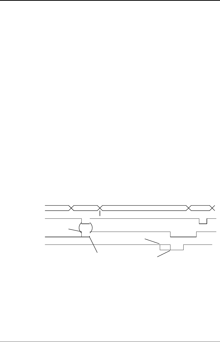
Programmer's Guide PcOS Series 150 Configuration Mode
12/14/99 Rev G Page 105
Vertical Control
The line spacing can be defaulted to six or eight lines per inch (lpi).
An auto line feed feature can be set as a default where all [CR]’s will have a [LF] added. If auto
line feed is set to on, this feature is activated. An auto line feed feature can be set as a default
where all [LF]’s will have a [CR] added. If auto CR is set to on, this feature is activated.
The default form length can be set from 3 to 17 inches. This configuration affects how the [FF]
command operates.
Character
The default print mode can be set to Draft, Utility, NLQ Courier, or NLQ Sans Serif. In most
cases, Draft or Utility mode will be the default selections.
The default print pitch can be set to 8, 10, 12, 15, 17.1, 20, or 24 characters per inch.
Interface
The Series 150 Printer has either a serial or parallel communications link. In the parallel
configuration, you can enable it as IEEE 1284, which allows a bidirectional mode.
The parallel option features define how the strobe, busy, and acknowledge signals operate. In
normal mode, the printer follows the standard (Centronics) parallel port conventions. With
Options 1 and 3, the acknowledge and busy signals change simultaneously. This is sometimes
referred to as Ack-after-Busy. Options 2 and 3 force busy high on the rising edge of strobe. This
is sometimes referred to Busy-while-Strobe timing. In all cases, the data is latched on the rising
edge of strobe. In most cases, the normal timing mode will give the best and most universal
results.
DATA
STROBE
BUSY
ACK
Pin 2-9
Pin 1
Pin 11
Pin 10
Data
Data
Options
1 and 3 Options
2 and 3
Normal
Normal
Figure 14 Parallel link options
The serial mode parity can be set to none, odd, or even. The serial bit format can be set to eight
or seven. The flow control protocol/serial link can be set to Ready/Busy or XON/XOFF. If
XON/XOFF is selected, Ready/Busy also functions.
The bit rate of the printer can be set to 19200, 9600, 4800, 2400, 1200, 600, or 300 bits per
second. The same bit rate is for both send and receive.

Configuration Mode PcOS Series 150 Programmer's Guide
Page 106 Rev G12/14/99
The serial port DTR and/or RTS signal can be configured to provide flow control. If DTR is
configured as the flow control signal, it will toggle to false when the buffer is full, RTS will not.
Options
The knife is an optional feature on the Series 150 Printer. If the hardware is installed, the
corresponding feature should be activated.
Save Changes
In self-configuration, the save changes must be set to “Yes” for any configuration changes to be
accepted. The next group selection will then save the changes and start normal operation.
Programmer's Guide PcOS Series 150 Communications
Overview
12/14/99 Rev G Page 107
Chapter 10:
Communications Protocol and Print
Buffers
Overview
The following figure illustrates the communication flow from the host computer to the printer and
from the printer to the cash drawer.
Host
computer
Printer to cash
drawer
Host to printer link
Cash
drawer Keypad
Host to
keypad
Printer
Figure 15 Typical POS system
For the host to printer communication link, the Series 150 Printer supports serial or parallel
communications. The serial and parallel port both follow standards developed for the personal
computer environment.
Host
Computer
Data to printer
Status and flow control back
Printer
Figure 16 Host to printer link
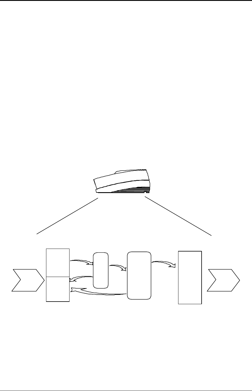
Communications PcOS Series 150 Programmer's Guide
Overview
Page 108 Rev G12/14/99
In most cases, the host computer is capable of sending information to the printer much faster than the
printer can print it. To prevent information from being lost, a flow control mechanism is provided.
This mechanism is called the flow control protocol. The goal of the flow control protocol is to
exchange as much information as possible as fast as possible without losing any data. The Series 150
Printer supports three flow control protocols, two in serial mode and one in parallel.
From the printer’s viewpoint, four basic functions are required of communications. All four are
common to all three flow control protocols. There must be a communication driver, status inquire
procedure, storage buffer, and print control mechanism that is using the data.
1. The communication port is either the serial port hardware or the parallel port hardware and the
associated communication software driver.
2. A means for the host to bypass the buffer for status information is also required because the
buffer offsets the printer in time from the host. (The printer is generally behind the host).
3. The storage print buffer is a software implemented, first-in/first-out (FIFO) circular buffer. It
stores information in an asynchronous fashion where information can be placed in it at any rate
and retrieved from it at any rate. However, the information order is not altered. Any buffer has a
finite size, and if information is put in faster than it is removed, it will overflow. To avoid
overflow, a flow control mechanism is required.
4. The print control mechanism is the remainder of the printer hardware and control software. It
interprets control codes and operates the control panel, print head, and cash drawer interface.
The following figure illustrates the four basic parts of printer flow control.
Data
Filling up/
emptying
Data
Communication
port Print buffer Print control
Serial or
parallel
connection Print head
Status
Data
Status
Printer
ENQ
processor
Data
Figure 17 Printer communications buffer flow
The communication port is either serial or parallel and is controlled by a software communication
driver. This driver receives data and returns requested status. As information is received from the
host, data is taken from the communication port hardware by the driver, preprocessed to look for
status inquire commands, and placed in the buffer. When the buffer input function finds that the
buffer is filling up, it notifies the communication driver to implement flow control. Flow control will
attempt to stop further information from being sent by the host.

Programmer's Guide PcOS Series 150 Communications
Overview
12/14/99 Rev G Page 109
The print control software takes information from the buffer (as it needs it and can use it). When the
buffer output function finds that the buffer is getting low, it notifies the communication driver that the
information flow can be resumed (if it was stopped) and allows more information to be placed in the
buffer.
The Series 150 Printer has a configurable input buffer. The printer can be configured to allow from
256 to 6144 bytes of input buffer. This means that up to 6144 characters (or control codes) can be sent
to the printer before they are interpreted and printed. In effect, the host computer can get 6144
characters ahead of the printer. In all cases, the buffer will resume communications when it is half
empty. For example, if the buffer is configured to be 2K, the printer will signal stop when 2048 bytes
are in the buffer. Resume will be signaled when 1024 bytes remain.
Inquire (ENQ) commands are preprocessed, which means they are found in the input data stream and
acted upon immediately as they are received. Therefore, the status returned is valid as of the time the
command is received. This is termed real-time status even though inquire commands are
preprocessed and still placed in the buffer. Real-time status assures that data is not lost when the
inquire sequence is part of another command. However, this also means that the buffer may be filled
by inquire commands, if the printer is waiting for some activity.
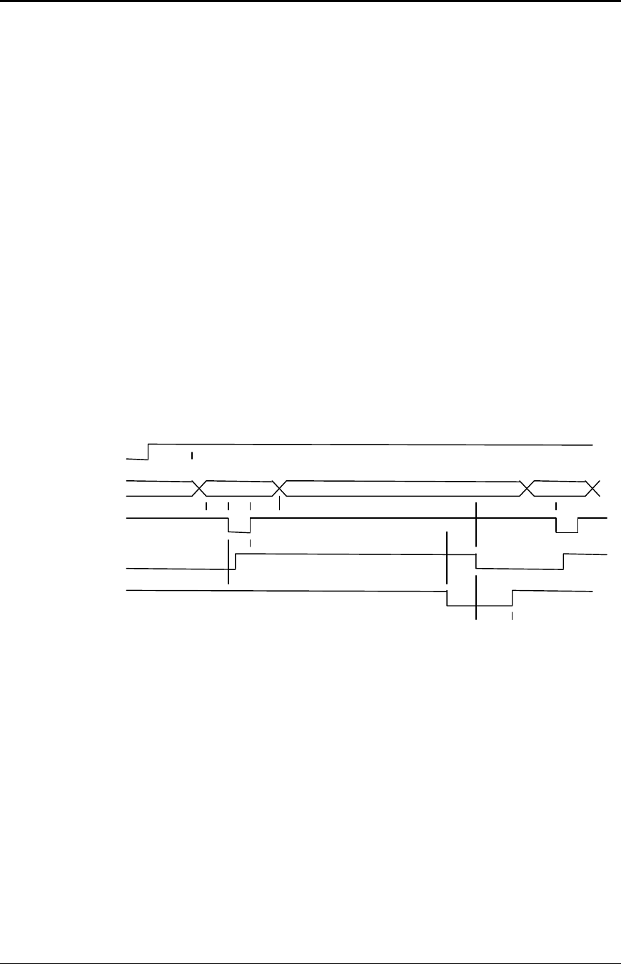
Communications PcOS Series 150 Programmer's Guide
Parallel Port
Page 110 Rev G12/14/99
Parallel Port
Parallel Port Protocol
The Series 150 parallel port behaves just like any printer connected to a personal computer. The
parallel interface accepts eight bits of data from the host. The strobe signal from the host is used
to indicate that data is available. When the printer sees the strobe and accepts the data, it asserts
a busy signal. The busy signal indicates to the host that the printer has accepted the data and is
busy working. When the printer has been able to absorb the data and is ready to accept another
byte, the printer asserts an acknowledge signal, negates busy, and finally negates acknowledge.
The following parallel port specifications and timing should be met by the host computer. In
standard personal computers, the strobe signal is generated by software writes to the parallel port
control port. This is typically done in the BIOS or in some parallel port driver. As personal
computers become faster, it is up to the software to assure that the strobe signal does not get too
narrow. One microsecond is about the minimum pulse width that should be sent down a cable.
Shorter pulse widths (500 nanoseconds) will be accepted by the printer; however, the cable can
introduce significant signal degeneration and skew.
It is important that the data be valid before the strobe signal is asserted and remain valid until
after the strobe is removed. A 500 nanosecond setup and hold time is required by the printer.
The following chart illustrates this sequence:
INIT
Pin 16
DATA
Pin 2-9
STROBE
Pin 1
BUSY
Pin 11
ACK
Pin 10
<-- Dhld
<--Tstb
Dstu---> < >
> Bhld---> <
Ahld ----> <
Sdly -----> <
Bhld approximately 5 us
Ahld approximately 5 us
Sdly 3 us (min)
Tcycle 200 - 280 us (typ)
Data
< ---- Rdly Data
Rdly approximately 2 s
Dstu 500 ns (min)
Dhld 500 ns (min)
Tstb 1 us (min)
<------------- ------------> Tcycle
Figure 18 Parallel port data timing
To implement flow control, the busy signal is asserted by the printer outside the normal data
transfer sequence.
The busy signal has several uses, but it always indicates that the printer cannot accept
information. The busy signal may happen at any time and may not adhere to the above timing
chart in all cases. It is up to the host's parallel port driver to handle all possible busy states. It is
important that the host driver does not hang-up if it takes time for an acknowledge response to a
strobe signal. The standard personal computer parallel port hardware implements an interrupt-
on-acknowledge signal to make this task easier.

Programmer's Guide PcOS Series 150 Communications
Parallel Port
12/14/99 Rev G Page 111
Printer Buffer Size
The Series 150 Printer has a configurable buffer size. It can be set from 256 bytes to 6144 bytes.
This allows an application to control how far ahead of the printer it can get. The smaller the
buffer is, the tighter the control will be. It is up to the application developer to select the optimal
buffer size.
One-line mode
The Series 150 Printer supports a one-line mode of operation. In this mode, the input buffer
is set to 1024 bytes; however, the printer will go busy after every [CR] received. In this
mode, the printer will stay busy after the [CR] is received and remain busy until the previous
information is printed. Several features must be considered when using one-line mode.
1. The printer only looks at [CR]’s. [LF] will cause the printer to print but will not set
busy.
2. If a [CR] character is received as part of another command, i.e, as part of graphics data,
the printer will go busy after the [CR] is received, but will go ready after the [CR] is
processed.
3. By definition, one-line mode is slow. The printer will not allow the application to get
ahead of the printer.
Parallel Port Inquire IEEE 1284
The Series 150 Printer supports the IEEE 1284 bidirectional parallel peripheral interface
standard. This standard provides for a bidirectional link on the parallel port. The Series 150
Printer supports Modes 0 and 4 only. This provides a nibble mode reverse channel for printer
identification and status inquire command. It is beyond the scope of this guide to describe the
IEEE 1284 protocol. The complete specification is available from:
The Institute of Electrical and Electronic Engineers, Inc.
345 East 47th Street
New York, NY 10017, USA
Buffer
The Series 150 Printer has a 256-byte buffer that contains information to be returned by the
IEEE 1284 reverse link. Information is placed in this buffer in the same format as RS-232
serial information is returned.
Inquire commands sent to the printer in IEEE 1284 mode will place responses to the
commands in the IEEE 1284 reverse channel buffer. This buffer is then transmitted to the
host when the host requests the reverse channel.
Mode 4
Mode 4 provides for the printer to return identification information to the host system. The
Series 150 Printer returns:
xx,yy (length of following data, 2 bytes with msb first)
MANUFACTURER: Ithaca-Peripherals;
COMMAND SET: IPCL;
MODEL:150;
COMMENT: Rev. x.xx;
ACTIVE COMMAND SET: IPCL;

Communications PcOS Series 150 Programmer's Guide
Parallel Port
Page 112 Rev G12/14/99
When a Mode 4 request is made, the IEEE 1284 buffer is cleared before the ID is sent.

Programmer's Guide PcOS Series 150 Communications
Parallel Port
12/14/99 Rev G Page 113
Mode 0
Mode 0 provides a reverse channel for information from the printer.
Normal responses to inquire (ENQ) commands will be placed in the IEEE 1284 reverse
channel buffer. The Mode 0 reverse channel request will begin returning this information to
the host. The host may terminate the transmission at any time. If the link is terminated
between nibbles, the last nibble is retransmitted on the next request. If a complete byte is
transmitted, it is deleted from the IEEE 1284 reverse channel buffer.
There is an inquire command that will clear the reverse channel buffer before placing its
response in the buffer.
The IEEE 1284 buffer is limited to 256 characters. If the buffer is not emptied by reverse
channel requests and data transfers, the buffer will overflow. The buffer is a first-in first-out
(FIFO) buffer, and the last data placed in the buffer is lost.
No attempt should be made to send normal data to the printer while the reverse channel is
active. Any data sent to the printer in this mode will be lost and may terminate the reverse
channel link.
Time-out
IEEE 1284 specifies a time-out for various phases of the protocol. The Series 150 Printer
treats these time-outs as minimums. The printer will time out at the specified time only if it
is idle during the complete phase.
Active State
The IEEE 1284 reverse channel may be activated at any time as long as the printer is not
busy with data. This means that if the printer is off-line the reverse channel may be
activated. If the printer is placed back on-line while the reverse channel is active, the printer
will not exit the reverse channel mode.
Inquire Responses
In general, inquire commands place two-byte responses in the IEEE 1284 reverse channel
buffer. The two bytes are the same as the serial mode responses. In IEEE 1284 mode, the
printer will remain busy until the inquire command is processed. This assures responses in
real time. To get the response, the host must ask for it. It is possible for the host to make a
number of requests and then get all the responses; however, the status returned will be valid
at the time the request was made.
It is possible for the dynamic response mode to be activated and the reverse channel opened.
The reverse channel will then change from reverse idle to reverse data available as the status
changes. The application must be careful in dynamic response mode that the dynamic
responses are not left active when the reverse channel is closed. If this happens, the buffer
will overflow. If there is data in the buffer when dynamic responses are activated, it will not
be replaced by current status. If dynamic response is off and a clear buffer command is issued
followed by activation of dynamic responses, the buffer will then contain fresh data. If the
buffer clear command is issued after the dynamic response is activated, the buffer will be
cleared and any unread responses will be lost.
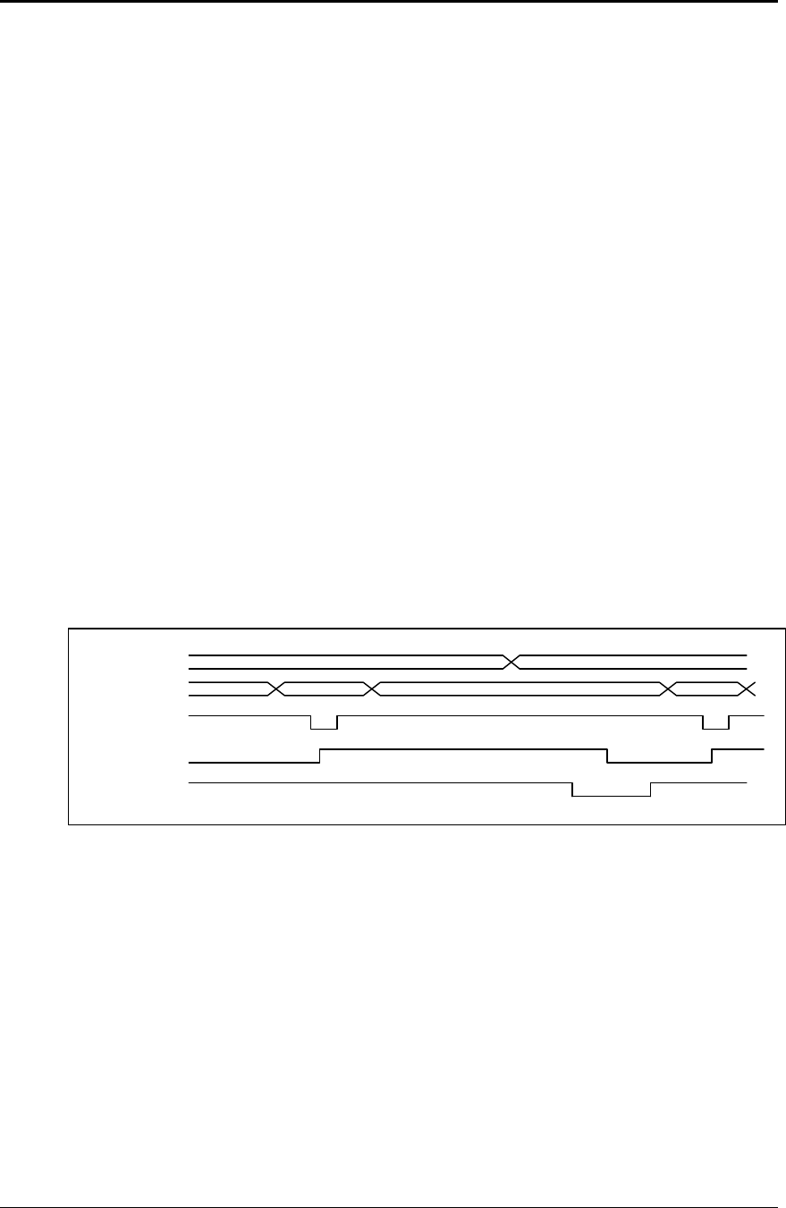
Communications PcOS Series 150 Programmer's Guide
Parallel Port
Page 114 Rev G12/14/99
Parallel Port Inquire (Non-IEEE 1284)
All inquire commands require a response from the printer. The serial port is bidirectional; the
non-IEEE 1284 parallel port is not. For this reason, the parallel, non-IEEE 1284 operation of
inquire commands is different from serial and IEEE 1284 modes. In serial and IEEE 1284
operation, inquire commands are responded to by an acknowledged (ACK) or not acknowleged
(NAK) sign and then the command ID on the return link.
In non-IEEE 1284 parallel operation, there is no easy way to return complex information to the
host. The paper error (PE) signal is driven in response to inquiries. If a true paper error is being
signaled, the ERR line will also be driven. It is, therefore, possible to distinguish between a paper
error and an inquire response.
In parallel, non-IEEE 1284 mode, the printer will respond to the inquire before the parallel port
sequence is complete. When the parallel port acknowledges the ID portion (the second byte) of
the inquire sequence, the PE signal will be valid. The host must, however, remember what status
request was made, as the printer has no way of signaling that information. In addition, the host
must not interpret the PE signal as an error but as a response to an inquiry.
The PE signal can be configured to respond in two ways. The first is static. The PE will remain
valid until the next inquire is issued. It may also be configured to operate dynamically which
means the PE signal will follow the status of the feature being tracked. In all cases, a true paper
error is dynamic. True paper error status will not override any other status request. For example,
if you want true paper error operation, it must be selected after all other dynamic status requests.
To synchronize inquire commands with the operation of the paper error signal, the printer will
remain busy after the second byte of an inquire command until the inquire command is
processed. This typically takes about 100 microseconds.
PE
DATA
STROBE
BUSY
ACK
Valid
ID Next
Figure 19 PE to ENQ request timing
It should be noted that inquire commands are preprocessed (looked at and processed before they
are buffered). They are still buffered. This means that the buffer could be filled with inquire
commands if the printer is waiting for some other operation.

Programmer's Guide PcOS Series 150 Communications
Parallel Port
12/14/99 Rev G Page 115
Parallel Port Plug and Play
Microsoft Windows implements Plug and Play (PnP) by doing an IEEE 1284 inquire during boot.
The Series 150 Printer will respond to this inquire if IEEE 1284 is active.
If the Windows PnP configuration flag is set in the printer, IEEE 1284 will be active for all
parallel port modes. For example, Windows PnP in parallel mode forces IEEE 1284. For PnP to
work, the host must have an IEEE 1284-compatible port adapter, and the cable used to connect to
the printer must support all the interface signals. The PnP response follows.
Device ID string:
MFG: Ithaca-Periph.;CMD:M150CL,IPCL;CLS:PRINTER;MDL S150 PcOS;DES:Ithaca-
Peripherals Series 150;REV:01.13;OPTS;$5xyz
PnP ID: LPTENUM\Ithaca-Periph.S150_PcECB3
Device Description: Ithaca-Peripherals Series 150
Device Class: PRINTER
The OPTS field is always as follows: OPTS;$5XYZ
Where X is a model definition, X and Y are bit fields that designate the options attached to the
printer.
Y X
Bit 0 →Alternate print zone Bit 0 →Slip capability
Bit 1 →Undefined Bit 1 →Knife module attached
Bit 2 →Undefined Bit 2 →MICR module attached
Bit 3 →0Bit 3 →0
Bits 4-5 →1Bits 4-5 →1
Bits 6-7 →0Bits 6-7 →0
The REV filed is the revision of the software installed in the printer.
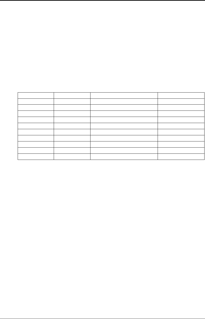
Communications PcOS Series 150 Programmer's Guide
Parallel Port
Page 116 Rev G12/14/99
Parallel Port Connector
The parallel printer interface is a 25-pin D-shell connector. The pin out is such that the printer
will interface to a standard personal computer parallel printer interface with a one to one cable.
The INIT\ (initialize) printer input acts as a hardware reset to the printer. This signal must be
inactive (high) for about four seconds before the printer will respond to information input.
The paper error signal is asserted by the printer whenever the journal paper is exhausted and an
attempt is made to print on the journal. The paper error signal is also asserted in response to
inquire (ENQ) commands in parallel, non-IEEE 1284 mode.
The ERR\ signal is asserted if a head jam occurs or if the paper error signal is asserted for a true
paper error. Note: The AUTOFD (auto feed, Pin 14) and SLIN (Select input, Pin 17) signals are
not used by the Series 150 Printer in parallel, non-IEEE 1284 mode.
Pin 1 STROBE Clock data to printer Host to Printer
Pin 2-9 D0 - D7 Data Host to Printer
Pin 10 ACK\ Printer accepted cata Printer to Host
Pin 11 BUSY Printer is busy Printer to Host
Pin 12 PE Paper out/status Printer to Host
Pin 13 SLCT Printer selected Printer to Host
Pin 14 AUTOFD Auto feed paper Host to Printer
Pin 15 ERR\ Printer error Printer to Host
Pin 16 INIT\ Initialize the printer Host to Printer
Pin 17 SLIN Select printer Host to Printer
Pin 18-25 GND Ground
Table 13 Parallel port pin-outs
Signal Levels
Voltage levels 0 V and +5 V (nominal)
Logic levels
Logic 1
Driver +2.4 V to +5 V
Receiver +2.0 V to +5 V
Logic 0
Driver 0 V to +0.4 V
Receiver 0 V to +0.8 V
Driver +2.4 V to +5 V
Current requirements
Logic 1 Source 0.25 ma at +2.4 V
Logic 0 Sink 16 ma
Line termination
Data and control 3.3 K ohm to +5 V
Strobe 1.2 K ohm to +5 V
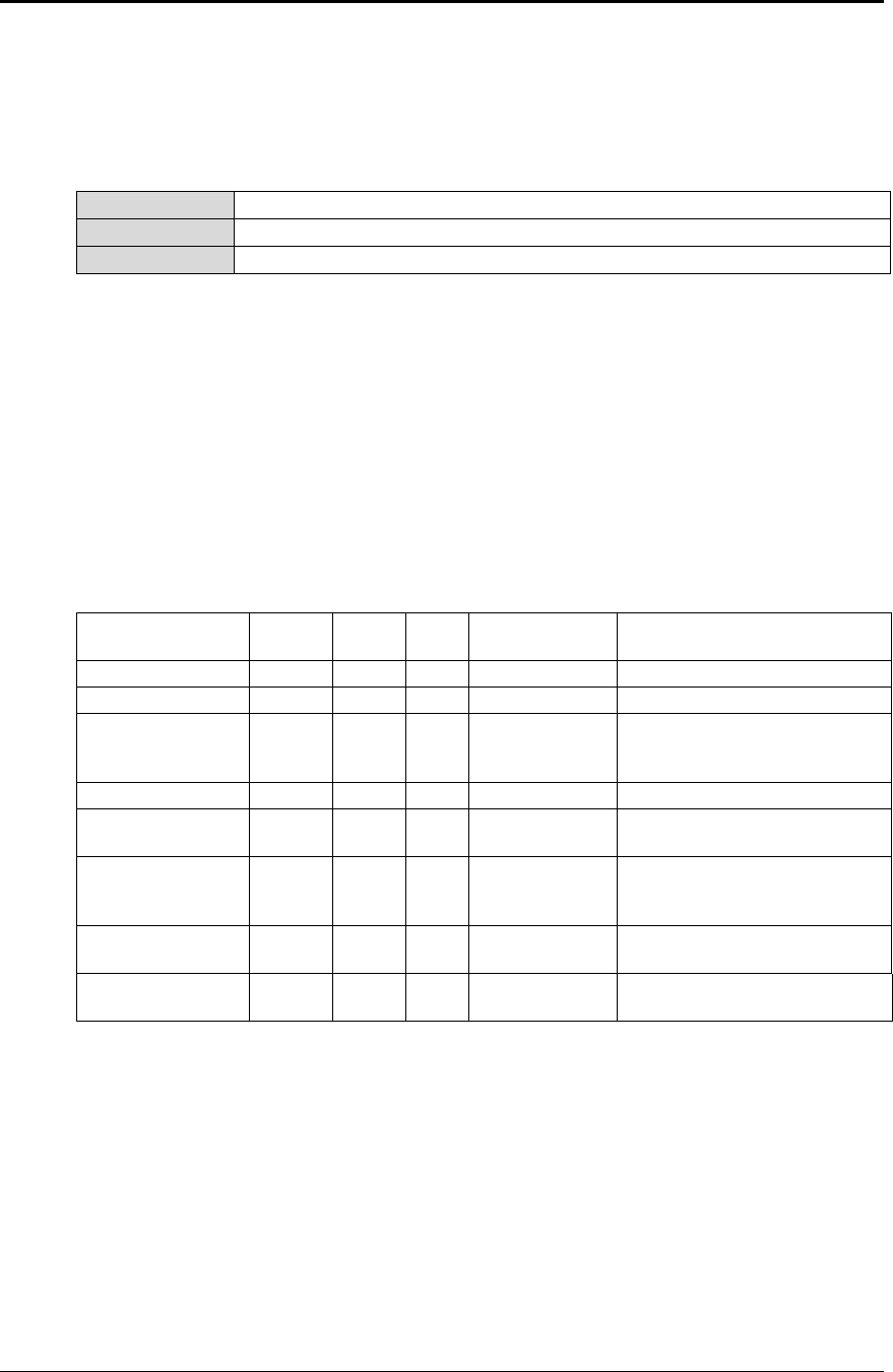
Programmer's Guide PcOS Series 150 Communications
Serial Port
12/14/99 Rev G Page 117
Serial Port
Serial Port Features
The serial port features are as follows:
Baud rates 300, 600, 1200, 2400, 4800, 9600, 19.2K
Bit patterns 8-bit, no parity; 8-bit odd; 8-bit even; 7-bit no parity; 7-bit odd; 7-bit even
Flow control DTR and XON/XOFF
Table 14 Serial bit rates
It should be noted that the 7-bit, no parity is in fact an 8-bit format. The implementation of the
hardware UART in the Intel 8051 family will not allow a true 7-bit, no parity format. If the host
provides a true 7-bit, no parity format, it must be configured with two stop bits.
The Series 150 Printer has a 64-character high-speed buffer before the main system buffer. This
high-speed buffer allows the printer to operate at high serial data rates while printing. Because
no data is evaluated in this buffer, the printer will have a delayed response to inquire requests
and [CR]’s in one-line operation. This has a significant effect on one-line mode operation.
Serial Port Pin-out
Not connected Input Pin 1 DCD Data carrier
detect Not used
Used in printer Input Pin 2 RX Receive data Commands/data to print
Output to host Output Pin 3 TX Transmit data Return data
Ready and/or flow
control signal to
host
Output Pin 4 DTR Data terminal
ready Printer ready to receive data
(follows buffer)
Pin 5 GND Signal ground
Disable printer
control from host Input Pin 6 DSR Data set ready Not used in standard printer
(configurable)
Ready and/or flow
control signal to
host
Output Pin 7 RTS Request to
send Printer ready to receive data
(follows buffer)
Flow control from
host Input Pin 8 CTS Clear to send Not used in standard printer
(configurable)
*Strapable 12 V or
DTR Output Pin 9 SSD Secondary
data Not used in standard printer
(provides power to peripheral)
Table 15 Serial port pin-outs
Because both the host and the printer are DTE's (Data Terminal Equipment), they use the same
serial port pin-outs. If the cable that is used to connect the host to the printer is a pin-to-pin
interconnect, it will not work. For this reason, a null modem or turn-around cable must be used to
interconnect the host and the printer.
Signal levels
The serial interface meets EIA RS-232 requirements.
Logic 1 -15 V to -3 V: mark = off
Logic 0 +3 V to +15 V: space = on
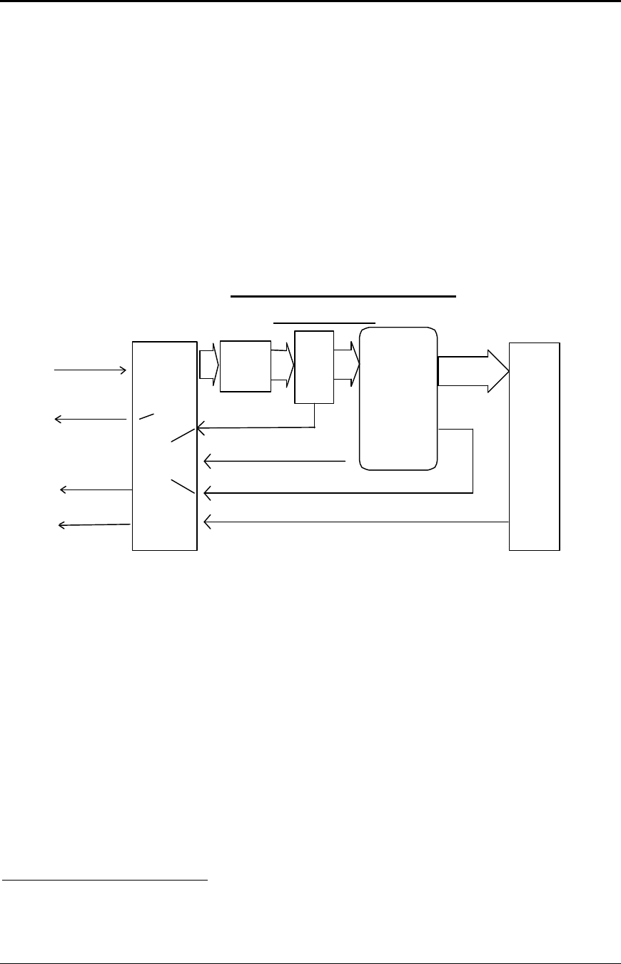
Communications PcOS Series 150 Programmer's Guide
Serial Port
Page 118 Rev G12/14/99
Serial Port Protocol
The serial port supports two flow control standards, XON/XOFF and Ready/Busy (sometimes
called DTR or hardware handshake.)
When Ready/Busy flow control is selected, the printer can be configured to use DTR, RTS, or
both for flow control. If only DTR is selected for flow control, RTS will indicate that the printer
has faulted. The following discussions will assume the DTR is being used for flow control.
The Ready/Busy protocol generally uses the DTR signal to indicate to the host computer that the
printer is not ready to accept data. The host should stop sending data to the printer as soon as
possible. Because the host may not notice the DTR signal until it has transmitted several bytes of
data to the printer, the printer will continue to except up to 25515 bytes of data after it indicates
that it is not ready. The figure below illustrates how the Ready/Busy protocol works.
Serial
Communications
port
Data
Buffer emptying
Select key
Printer
control
software
Print
buffer
Serial Port Flow Control
Using DTR
RTS -> Request to send DTR -> Data terminal ready
data in
Serial
data out
(Not used for
flow control)
DTR
RTS
DTR
Clear
Set
Inquire
response
256 - 6K
Data
Buffer filling up
Data
High
speed
FIFO
ENQ response
Data
ENQ
proc.
Figure 20 Serial port flow control using DTR
15The buffer always signals it is full before it overflows. The size of the reserve depends on the buffer size
selected. It is always at least 255 bytes.
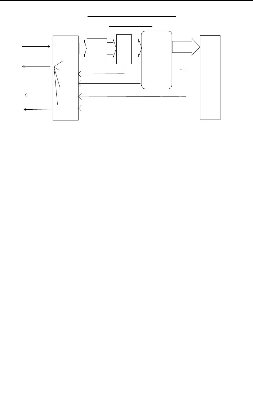
Programmer's Guide PcOS Series 150 Communications
Serial Port
12/14/99 Rev G Page 119
Serial
Communications
port
Data
Buffer filling up
Buffer emptying
Data
Select key
Printer
control
software
Print
buffer
256 - 6K
Serial Port Flow Control
XON/XOFF
RTS -> Request to send DTR -> Data terminal ready
data in
Serial
data out
(Not used for
flow control)
DTR
RTS
Send
XOFF
Send
XON
Send
XON or XOFF
Inquire
commands
Data
High
speed
FIFO
ENQ response
Data
ENQ
Proc.
Figure 21 Serial port flow control XON/XOFF
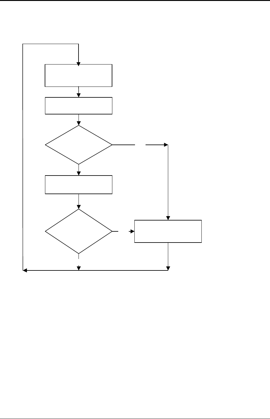
Communications PcOS Series 150 Programmer's Guide
Serial Port
Page 120 Rev G12/14/99
Print Buffer Flow
The following flow chart illustrates the communication driver getting data from the serial port
and placing the data in the buffer using Ready/Busy or XON/XOFF flow control.
At the top of the flow chart, the driver is waiting for data. When data is received from the host,
the printer checks to see if it is an inquire command. If the data is an inquiry, it is responded to
and placed in the buffer. If not, the data is placed directly into the buffer. The buffer is then
checked to see if it is full before the internal pointer is incremented. If it is not full, the pointer is
incremented in preparation for the next data byte. The buffer is then checked to see if it is getting
full by checking the amount of information in the buffer to see if it has passed a high watermark.
If it has, the communication driver is notified, and it resets data terminal ready (DTR) to indicate
to the host that no more data should be sent.
Wait for data from the
host in high speed
FIFO buffer.
Place data in print
buffer.
Is the buffer
past the high
watermark? Yes Clear the DTR signal
or transmit XOFF.
DTR - Data Terminal Ready
No
Update buffer pointers.
Is the buffer
full? Yes
Figure 22 Serial buffer operation

Programmer's Guide PcOS Series 150 Communications
Serial Port
12/14/99 Rev G Page 121
The following flow chart illustrates how the print controller takes information from the buffer
and controls flow. At the top of the chart, the print control software asks for data. If there is no
data in the buffer, a no data flag is returned. The print software must then wait for data. If there
is data in the buffer, it is read and pointers are updated. The buffer is then checked to see how
much information is left. If the buffer is below a low watermark (about 100 bytes left), the
communication driver is notified, and DTR is reasserted.
If XON/XOFF flow control is being used, the flow is similar to DTR flow except that DTR is not
used and XON/XOFF control characters are transmitted back to the host on the serial link.
XON/XOFF has an advantage over DTR in that only three wires are required to interconnect to a
printer. The disadvantage is that a serial port receiver driver must be written for the host.
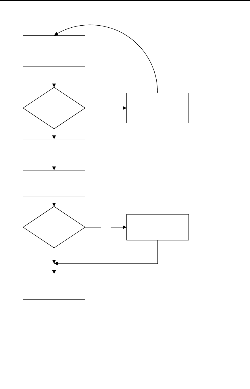
Communications PcOS Series 150 Programmer's Guide
Serial Port
Page 122 Rev G12/14/99
The print controller is always looking for data when the printer is on-line and not printing. It
continuously asks the buffer if it has any data. If there is no data in the buffer, it does
housekeeping chores like keyboard scanning. If there is data, it processes it. The flow control is
done when the data is taken from the buffer and the amount of data in the buffer is less than a
prescribed amount. This low watermark is set based on the expected environment. The Series 150
Printer sets this at 200 characters, which gives the host application time to get more data to the
printer before the printer uses up what it has.
The print controller
needs data to print or a
command to decode.
Is there any
data in the
buffer? No Return to print
controller with no data
available.
Aquire data from the
buffer.
Move buffer pointers to
the next data byte.
Is the buffer
below the low
watermark? Yes
No
Set DTR or
transmit XON.
Return data to print
controller.
DTR = Data Terminal Ready
Loop through idle
task, and then look
for more data.
Figure 23 Print controller using data

Programmer's Guide PcOS Series 150 Communications
Serial Port
12/14/99 Rev G Page 123
When XON/XOFF protocol is implemented, it is possible for the host to miss an XON or an
XOFF. To prevent this from causing a communication lockup, the printer will send an XOFF for
every character received after the high watermark is reached.
Whenever the printer detects that the serial data link is inactive, it will send out an XON. This
results in an XON being sent out about every two seconds.
When the printer is selected or deselected (with the SELECT key), an XON or XOFF will also be
sent. This happens even if the internal data buffer is past the high watermark16 and tells the host
that the SELECT key has been pressed. If the buffer is full and an XON is sent, the next
character sent by the host will cause an XOFF to be sent. The data that was sent by the host will
not be lost unless the 255-character pad buffer is depleted.
Printer Buffer Size
The Series 150 Printer has a configurable buffer size. It can be set from 256 bytes to 6144 bytes
(This does not include the 64-character high-speed buffer). This allows an application to control
how far ahead of the printer it can get before being asked to wait. The smaller the buffer is, the
tighter the control. It is up to the application developer to select the optimal buffer size.
One-line Mode
The Series 150 Printer supports a one-line mode of operation. In this mode, the input buffer
is set to 1024 bytes; however, the printer will go busy after every [CR] is received by the
printer. In this mode, the printer will stay busy after the [CR] is received and remain busy
until the previous information is printed. This mode is not recommended for serial operation
unless the application looks for the line terminator handshake. Several features must be
considered when using this mode.
1. The printer only looks at [CR]’s. [LF] will cause the printer to print but will not set
busy.
2. If a [CR] character is received as part of another command, i.e., as part of graphical
data, the printer will go busy after the [CR] is received and will go ready after the [CR]
is processed.
3. By definition, one-line mode is slow. The printer will not allow the application to get
ahead of it.
4. In serial mode, one-line mode is difficult to control. Because of the 64-character high-
speed FIFO buffer, the printer will not go busy immediately after the [CR] is sent. It may
take up to 25 milliseconds for the printer to process the [CR]. During this time, it is
possible for the application to send up to 48 bytes of data to the printer. When the [CR]
is found in the input stream, the busy status will be set. If the application continues to
send information, the input buffer will be overrun as it only has 16 bytes left. In
addition, the application will not truly be in one-line operation. The application must
wait for at least 100 milliseconds after a [CR] before looking for busy status or trying to
send more data.
5. In XON/XOFF mode, the printer is heavily burdened by the task of transmitting XOFF
characters while printing and receiving data. The application should be written to look
for the XOFF after every [CR]. The Series 150 Printer will lose data if too many
characters follow the XOFF.
16If the host sends more information, it will be responded to by an XOFF.
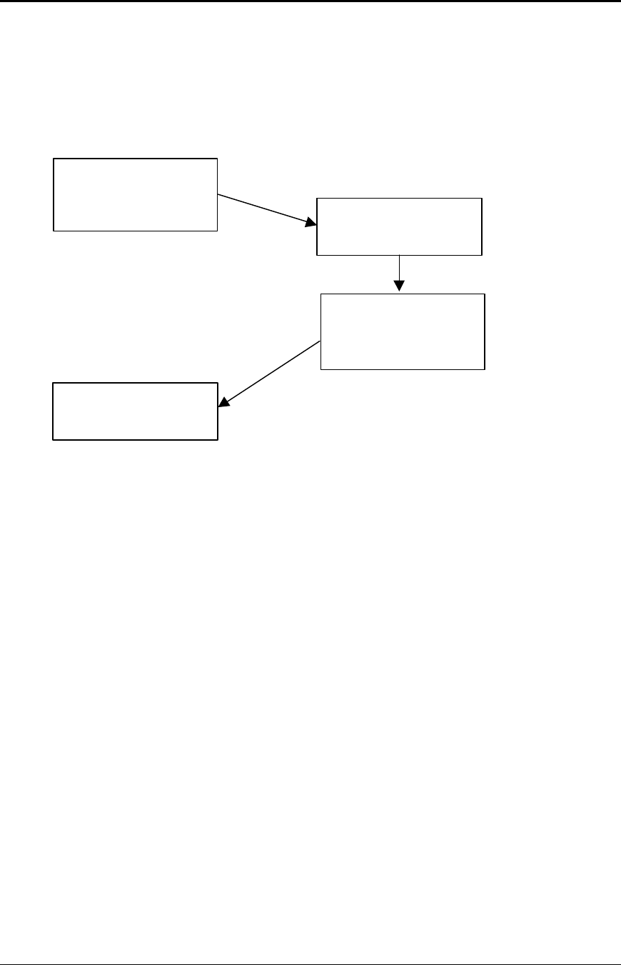
Communications PcOS Series 150 Programmer's Guide
Serial Port
Page 124 Rev G12/14/99
Serial Port Inquire
The serial port inquire is more straightforward than parallel mode. The serial acknowledge
(ACK) or not-acknowledge (NAK) responses follow a uniform format. The ACK or NAK is
always followed by the command ID that requested it. This makes the design of the host
application easier because the response can be identified and always follows the same format.
Figure 24 is an example of a host/printer inquiry response exchange.
Figure 24 Inquire flow
The host sends an [ENQ]<id> (form sensor status) request to the printer. The printer responds
with an [ACK]<id> indicating that the request was identified, and the status is true.
Inquire (ENQ) commands effect the printer’s performance. The priority for communication in
the printer is very high. ENQ commands take processing away from print tasks. It is possible to
ask for so much status that the printer slows.
In serial mode, it is important that the response to an inquire be received by the host before
another command is issued. When an inquire is received by the printer, it is buffered in a high-
speed process queue. When the printer has time, it empties the queue and processes the inquires.
The printer responds to the command as soon as the second byte of the command is taken from
the high-speed buffer. If the host is looking for a form to be inserted, it should not send status
requests as fast as it can. The host will get a response to all of them, and if the host did not wait
for a response to each, there would be unnecessary responses.
In IEEE 1284 mode, inquiry responses are placed in an IEEE 1284 transmit queue. When the
IEEE 1284 reverse channel is opened, the responses are returned to the host. It is important that
after each request, the reverse channel be opened. Inquire responses will remain in the queue
until read. If the [ENQ] <9> command is sent to the printer, the IEEE 1284 buffer will be cleared
and only the response to the [ENQ] <9> will remain.
The host sends an
[ENQ] to the printer
asking for the form
sensor status. The printer receives the
request and
preprocesses it.
The printer responds
with an [ACK] <id> or
[NAK] <id> indicating
the form sensor status.
The host receives the
response and decodes
it.

Programmer's Guide PcOS Series 150 Communications
Programmer’s Notes
12/14/99 Rev G Page 125
Remote Printer Reset
Reset in Serial Mode
It is possible to generate a printer reset in serial mode. The [ENQ] <10> command will request
that the printer reset. (This is not a hardware reset). It will, however, completely initialize the
hardware and software but will not recover from a loss of software control.
Note: If the printer mode was changed by the [ESC] y <2> or [ESC] y <3> command, a soft reset
will not return to the power on default.
The command flow follows.
1. The [ENQ] <10> will be acknowledged, and then the software will reset.
2. The printer will be placed off-line.
3. The hardware and software will be reinitialized.
4. The printer will then go back on-line. Any information sent to the printer while it is off-line
will be lost.
Reset in Parallel Mode
In parallel mode, driving the INIT signal on the parallel port for 100 milliseconds will generate a
software reset. It will take about two seconds for the printer to recover from a reset. The [ENQ]
<10> command will be rejected if parallel mode is active.
Power-cycle Recovery
There are times when the host needs to know if the printer was power cycled. An example would be
after changing the receipt tape. It is not necessary to turn off the printer to change the receipt.
However, if the operator does, any information sent to the printer before the power cycle will be lost.
The Series 150 Printer has a flag that is set after a reset. The flag stays set until it is requested by the
host; at which time, it is reset. The [ENQ] <11> command reads the flag. If the command returns
power-cycled status, the power has been reset or power cycled since the last request and all unprinted
information has been lost.
If the print operation is critical, it is a good idea to check the flag before and after all transactions. An
alternate approach is to check the flag after every off-line to on-line transition.
Note: If the printer mode was changed by the [ESC] y <2> or [ESC] y <3> command, a power-cycle
reset will return to the power on default.

Communications PcOS Series 150 Programmer's Guide
Remote Printer Reset
Page 126 Rev G12/14/99
Programmer’s Notes
When the serial port is being used, it is important that the output lines from the printer not be shorted
or back driven. If the signals are not to be used, they should be left open.
Pins 3, 4, and 7 are outputs from the printer. If any one of these signals is grounded or back driven,
the other two outputs will be degraded.
The best time to configure the printer by the host is during system setup or software update.
The printer should be power cycled after configuration to assure that the new configuration takes
effect.
In serial mode, one-line mode should be avoided, particularly in XON/XOFF mode. The high speed
FIFO input buffer makes one-line mode difficult to process.
If the knife module fails at any time, the configuration can be changed to deactivate the option and
the printer will not ask it for status. This will allow the printer to be used without the option until the
printer can be repaired.
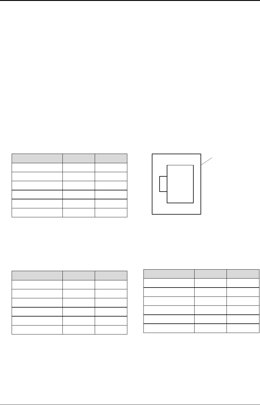
Programmer’s Guide PcOS Series 150 Cash Drawer Interface
12/14/99 Rev G Page 127
Chapter 11:
Cash Drawer Interface
Interface Description
The Series 150 Printer supports dual cash drawers with status. The driver in the printer is capable of
supplying 24 VDC at up to 1.5 amps and 250 milliseconds. The Series 150 Printer defines cash
drawer closed as switch open. If the drawer is disconnected, it will be viewed by the printer as closed.
Since the printer does not act on the cash drawer status, the application can interpret cash drawer
status any way it wants.
Interface Connectors
There are two cash drawer connectors. One is configured as Cash Drawer 1, the other as Drawer 2.
The pin out is as follows:
Function Drawer 1 Drawer 2
Drawer Drive + Pin 4 Pin 4
Drawer Drive - Pin 5 Pin 1
Status Signal Pin 2 Pin 2
Status Ground Pin 3 Pin 3
Frame Ground Pin 6 Pin 6
No Connect Pin 1 Pin 5
Table 16 Ithaca cash drawer connector
Note: Cash Drawer 2 can be factory configured to be the same as Drawer 1.
Function Drawer 1 Drawer 2
Drawer Drive + Pin 4 Pin 4
Drawer Drive - Pin 2 Pin 5
No Connect Pin 5 Pin 2
Status Signal Pin 3 Pin 3
Status Ground Pin 6 Pin 6
Frame Ground Pin 1 Pin 1
Table 17 Epson/Axiohm cash drawer
connector
Function Drawer 1 Drawer 2
Drawer Drive - Pin 2 Pin 2
Drawer Drive + Pin 3 Pin 3
Status Signal Pin 6 Pin 6
Frame Ground Pin 1 Pin 1
No Connect Pin 4 Pin 4
No Connect Pin 5 Pin 5
Table 18 Star cash drawer connector
Pin 1

Printing Graphics PcOS Series 150 Programmer’s Guide
Page 128 Rev G 12/14/99
Chapter 12:
Printing Graphics
The Series 150 Printer has bit image graphic capabilities and a full PC-compatible graphic character set.
The bit image format is similar to that used on other personal computer printers. There are three modes of
operation: single-density, half-speed double-density, and full-speed double-density.
Single-density is the fastest mode. It makes a single, unidirectional, 60 dpi print pass. The full-speed
double-density makes two passes with a half-dot offset. This mode is half the speed of single-density print
but will print at 120 dpi. Half-speed double-density is half the speed of full-speed double-density;
however, the print quality is enhanced.
Character Graphics
Character graphics are created by joining individual characters together to produce a mosaic of
characters that form a graphic image. The simplest method is to use the * (or any other character) to
form an image. For example, ITHACA might be formed as follows.
*** *** * * ** *** **
* * * * * * * * * *
* * ***** **** * ****
* * * * * * * * * *
*** * * * * * *** * *
The extended character set of the printer supports line graphic characters that can be combined to
form windows and other shapes. For the shapes to join from line to line, the line spacing must be set
properly.
All characters are in a 9-dot-high character cell. The dots are 1/60 inch apart. Therefore, the line
spacing should be 10/60 or 1/6 inch. The set fine line space command can be used to set this line
spacing. If possible, the spacing should be reduced slightly to overlap the rows. This prevents any
white space from appearing between the lines. The following example illustrates the use of extended
graphic characters.
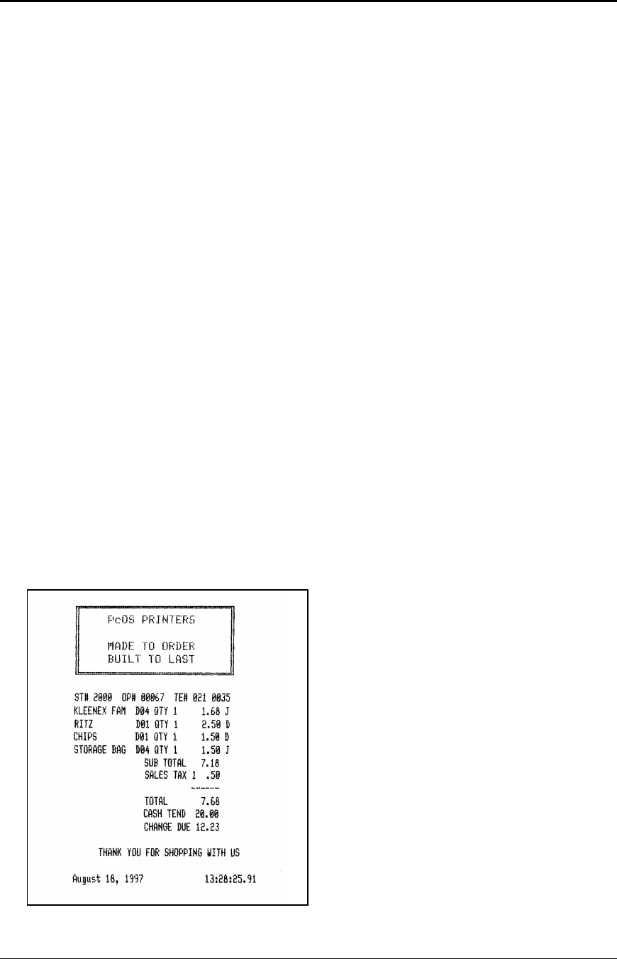
Programmer's Guide PcOS Series 150 Printing Graphics
12/14/99 Rev G Page 129
[ESC]U<1> Select unidirectional print for better alignment.
[ESC]: Select 12 cpi.
[ESC]3<34> Set line spacing to 0.157 inch. (This is slightly smaller than 1/6 inch.)
<201> Send the line graphic characters to the printer.
<205><205><205><205><205><205><205><205><205>
<205><205><205><205><205><205><205><205><205>
<205><205><205><205>
<187>[CR][LF]
<186> PcOS PRINTERS <186>[CR][LF]
<186> <186>[CR][LF]
<186> MADE TO ORDER <186>[CR][LF]
<186> BUILT TO LAST <186>[CR][LF]
<200>
<205><205><205><205><205><205><205><205><205>
<205><205><205><205><205><205><205><205><205>
<205><205><205><205>
<188>[CR][LF] This finishes the line graphics.
[ESC]U<0> Reenable bidirectional printing.
[ESC]0 Set standard 1/8-inch line spacing.
[SI] Set 17 cpi.
[CR][LF] Finish the form.
ST# 2000 OP# 00067 TE# 021 0035[CR][LF]
KLEENEX FAM D04 QTY 1 1.68 J[CR][LF]
RITZ D01 QTY 1 2.50 D[CR][LF]
CHIPS D01 QTY 1 1.50 D[CR][LF]
STORAGE BAG D04 QTY 1 1.50 J[CR][LF]
SUB TOTAL 7.18[CR][LF]
SALES TAX 1 .50[CR][LF]
------[CR][LF]
TOTAL 7.68[CR][LF]
CASH TEND 20.00[CR][LF]
CHANGE DUE 12.23[CR][LF]
[CR][LF]
[ESC]a<1>
THANK YOU FOR SHOPPING WITH US[CR][LF]
[ESC]a<0>
[CR][LF]
{DATE:0} {TIME:0}[CR][LF]
Figure 25 Receipt with extended graphic
characters
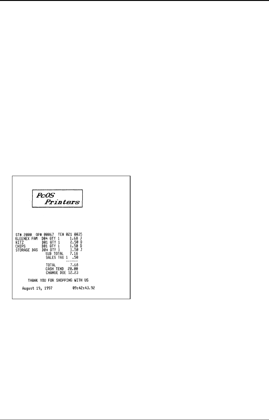
Printing Graphics PcOS Series 150 Programmer's Guide
Page 130 Rev G12/14/99
When printing line graphics, the data path to the printer must be eight bits. Seven-bit serial protocols
will not access the extended characters. The extended characters require that the form be reverse fed.
This means that printing line graphics on the receipt may be less than acceptable.
APA Graphics
The printer is capable of all-points-addressable (APA) graphics. Generating a graphic image by hand
is time consuming and tedious. It is possible to use a graphic package to create a graphic image. The
following procedure will help with the setup.
1. Generate the graphic image in the program of your choice.
2. Make sure the paper size you choose will fit the printer station. If the paper size cannot be set,
print a portion of the page.
3. Print the graphic to a file using a generic, IBM, graphic, 9-pin driver. The standard IBM
resolutions are: 240 x 216 dpi, 120 x 72 dpi, and 60 x 72 dpi. The Series 150 Printer supports all
three resolutions. For good resolution with reasonable speed, use 120 x 72 dpi.
4. Print the graphic image to a file.
5. Edit the resulting file to remove any unwanted form control, and insert the Series 150 form
control.
6. Make the resulting file available to your application, so it will be sent to the printer when
required.
Figure 26 Receipt with APA graphics
As with all graphics, the data path to the printer must be eight bits; 7-bit protocols will not work.
The quad-density graphic resolution will give the best rendition of your graphic image; however, this
mode is slow and prints dark. The printer is setup to provide the best performance in normal
operation. For this reason, quad-density graphics should be limited.
The APA graphic example above was done with double-density graphics. The graphic driver used
made an approximation of the graphic image.
The first part of the graphic file is listed here in hex. This is a hex dump of the first 512 bytes of the
graphic file printed on the above receipt.

Programmer's Guide PcOS Series 150 Printing Graphics
12/14/99 Rev G Page 131
0100 1B 43 00 0B 0D 0C 46 1B-48 1B 49 01 1B 54 1B 55 .C....F.H.I..T.U
0110 00 1B 55 00 1B 46 1B 49-01 1B 66 0D 34 00 8B 0D ..U..F.I..f.4...
0120 1B 55 01 1B 59 60 01 00-00 00 00 00 00 00 00 00 .U..Y`..........
0130 00 00 00 00 00 00 00 00-00 00 00 00 00 00 00 00 ................
0140 00 00 00 00 00 00 00 00-00 00 00 00 00 00 00 00 ................
0150 00 00 00 00 00 00 00 00-00 00 00 00 00 00 00 00 ................
0160 00 00 00 00 00 00 03 01-02 01 02 01 02 01 02 01 ................
0170 02 01 02 01 02 01 02 01-02 01 02 01 02 01 02 01 ................
0180 02 01 02 01 02 01 02 01-02 01 02 01 02 01 02 01 ................
0190 02 01 02 01 02 01 02 01-02 01 02 01 02 01 02 01 ................
01A0 02 01 02 01 02 01 02 01-02 01 02 01 02 01 02 01 ................
01B0 02 01 02 01 02 01 02 01-02 01 02 01 02 01 02 01 ................
01C0 02 01 02 01 02 01 02 01-02 01 02 01 02 01 02 01 ................
01D0 02 01 02 01 02 01 02 01-02 01 02 01 02 01 02 01 ................
01E0 02 01 02 01 02 01 02 01-02 01 02 01 02 01 02 01 ................
01F0 02 01 02 01 02 01 02 01-02 01 02 01 02 01 02 01 ................
0200 02 01 02 01 02 01 02 01-02 01 02 01 02 01 02 01 ................
0210 02 01 02 01 02 01 02 01-02 01 02 01 02 01 02 01 ................
0220 02 01 02 01 02 01 02 01-02 01 02 01 02 03 00 00 ................
0230 00 00 00 00 00 00 00 00-00 00 00 00 00 00 00 00 ................
0240 00 00 00 00 00 00 00 00-00 00 00 00 00 00 00 00 ................
0250 00 00 00 00 00 00 00 00-00 00 00 00 00 00 00 00 ................
0260 00 00 00 00 00 00 00 00-00 00 00 00 00 00 00 00 ................
0270 00 00 00 00 00 00 00 00-00 00 00 00 00 00 00 00 ................
0280 00 00 00 00 00 00 00 1B-55 00 1B 4A 18 0D 1B 55 ........U..J...U
0290 01 1B 59 60 01 00 00 00-00 00 00 00 00 00 00 00 ..Y`............
02A0 00 00 00 00 00 00 00 00-00 00 00 00 00 00 00 00 ................
02B0 00 00 00 00 00 00 00 00-00 00 00 00 00 00 00 00 ................
02C0 00 00 00 00 00 00 00 00-00 00 00 00 00 00 00 00 ................
02D0 00 00 00 00 FF FF 00 00-00 00 00 00 00 00 00 00 ................
02E0 00 00 00 00 00 00 00 00-00 00 00 00 02 01 02 01 ................
02F0 02 00 02 00 02 00 02 01-02 01 00 00 00 00 00 00 ................

PcOS Series 150 Programmer’s Guide
Page 132 Rev G 12/14/99
Programmer's Guide PcOS Series 150 Appendix A
12/14/99 Rev G Page 133
Appendix A
Language Tables
Code
Page
Country Code/
Language Set
Decimal
<n1> <n2>
Hex
<n1> <n2>
ASCII
<n1> <n2> <n3>
Epson ID
64 USA (slashed 0) 0,64 0H,040H 0,0,6,4 NA
65 USA (unslashed 0) 0,65 0H,041H 0,0,6,5 NA
66 British 0,66 0H,042H 0,0,6,6 3
67 German 0,67 0H,043H 0,0,6,7 2
68 French 0,68 0H,044H 0,0,6,8 NA
69 Swedish I 0,69 0H,045H 0,0,6,9 5
70 Danish I 0,70 0H,046H 0,0,7,0 NA
71 Norwegian 0,71 0H,047H 0,0,7,1 NA
72 Dutch 0,72 0H,048H 0,0,7,2 14
73 Italian 0,73 0H,049H 0,0,7,3 NA
74 French Canadian 0,74 0H,04AH 0,0,7,4 13
75 Spanish I 0,75 0H,04BH 0,0,7,5 NA
76 Swedish II 0,76 0H,04CH 0,0,7,6 15
77 Swedish III 0,77 0H,04DH 0,0,7,7 16
78 Swedish IV 0,78 0H,04EH 0,0,7,8 17
79 Turkish 0,79 0H,04FH 0,0,7,9 18
80 Swiss I 0,80 0H,050H 0,0,8,0 19
81 Swiss II 0,81 0H,051H 0,0,8,1 20
90 Publisher 0,90 0H,05Ah 0,0,9,0 64
437 USA 1,181 1H,0B5H 0,4,3,7 0
774 Baltic 3,6 3H,006H 0,7,7,4 74
850 Multilingual 3,82 3H,052H 0,8,5,0 26
852 East European Latin II 3,84 3H,054H 0,8,5,2 46
855 Cyrillic I 3,87 3H,057H 0,8,5,5 44
857 Turkey 3,89 3H,059H 0,8,5,7 57
860 Portugal 3,92 3H,05CH 0,8,6,0 28
861 Icelandic 3,93 3H,05DH 0,8,6,1 73
862 Hebrew NC 3,94 3H,05EH 0,8,6,2 60
863 Canada French 3,95 3H,05FH 0,8,6,3 43
865 Norway 3,97 3H,061H 0,8,6,5 27
866 Cyrillic II 3,98 3H,062H 0,8,6,6 45
869 Greek_869 3,101 3H,065H 0,8,6,9 47
Appendix A PcOS Series 150 Programmer's Guide
Page 134 Rev G12/14/99
Code
Page
Country Code/
Language Set
Decimal
<n1> <n2>
Hex
<n1> <n2>
ASCII
<n1> <n2> <n3>
Epson ID
895 Kamenicky (MJK) 3,127 3H,07FH 0,8,9,5 55
1008 Greek 437 3,240 3H,0F0H 1,0,0,8 38
1009 Greek 928 3,241 3H,0F1H 1,0,0,9 39
1011 Greek 437 CYPRUS 3,243 3H,0F3H 1,0,1,1 41
1012 Turkey 3,244 3H,0F4H 1,0,1,2 29
1014 Polska Mazovia 3,246 3H,0F6H 1,0,1,4 22
1015 ISO Latin 2 3,247 3H,0F7H 1,0,1,5 23
1016 Serbo Croatic I 3,248 3H,0F8H 1,0,1,6 24
1017 Serbo Croatic II 3,249 3H,0F9H 1,0,1,7 25
1018 ECMA-94 3,250 3H,0FAH 1,0,1,8 42
1019 Windows East Europe 3,251 3H,0FBH 1,0,1,9 49
1020 Windows Greek 3,252 3H,0FCH 1,0,2,1 50
1021 Latin 5 Windows Turkey 3,253 3H,0FDH 1,0,2,2 51
1022 Windows Cyrillic 3,254 3H,0FEH 1,0,2,4 52
1024 Hungarian CWI 4,0 4H,000H 1,0,2,5 54
1026 ISO Latin 4 4,2 4H,002H 1,0,2,6 56
1027 Ukrainian 4,3 4H,003H 1,0,2,7 66
1028 Roman-8 4,4 4H,004H 1,0,2,8 58
1029 ISO Latin 6 4,5 4H,005H 1,0,2,9 67
1031 Hebrew OC 4,7 4H,007H 1,0,3,0 61
1032 Windows Hebrew 4,8 4H.008H 1,0,3,2 62
1033 KBL-Lithuanian 4,9 4H,009H 1,0,3,3 63
1034 Windows Baltic 4,10 4H,00AH 1,0,3,4 68
1035 Cyrillic-Latvian 4,11 4H,00BH 1,0,3,5 69
1072 Bulgarian 4,48 4H,030H 1,0,7,2 72
NA French 1
NA Danish I 4
NA Italian 6
NA Spanish I 7
NA Japanese 8
NA Norwegian 9
NA Danish II 10
NA Spanish II 11
NA Latin American 12
Table 19 Code page definitions
Note: There is a demonstration script distributed with the CFG150 program that will print a complete
character chart for IBM or EPOS modes. See the CFG150 distribution disk.

Programmer’s Guide PcOS Series 150 Appendix B
12/14/99 Rev G Page 135
Appendix B
ASCII Code Chart
HEX Decimal ASCII
00 0 NULL
01 1 SOH
02 2 STX
03 3 ETX
04 4 EOT
05 5 ENQ
06 6 ACK
07 7 BEL
08 8 BS
09 9 HT
0A 10 LF
0B 11 VT
0C 12 FF
0D 13 CR
0E 14 SO
0F 15 SI
10 16 DLE
11 17 DC1
12 18 DC2
13 19 DC3
14 20 DC4
15 21 NAK
16 22 SYN
17 23 ETB
18 24 CAN
19 25 EM
1A 26 SUB
1B 27 ESC
1C 28 FS
1D 29 GS
1E 30 RS
1F 31 US
HEX Decimal ASCII
20 32 (SP)
21 33 !
22 34 "
23 35 #
24 36 $
25 37 %
26 38 &
27 39 '
28 40 (
29 41 )
2A 42 *
2B 43 +
2C 44 ,
2D 45 -
2E 46 .
2F 47 /
30 48 0
31 49 1
32 50 2
33 51 3
34 52 4
35 53 5
36 54 6
37 55 7
38 56 8
39 57 9
3A 58 :
3B 59 ;
3C 60 <
3D 61 =
3E 62 >
3F 63 ?
HEX Decimal ASCII
40 64 @
41 65 A
42 66 B
43 67 C
44 68 D
45 69 E
46 70 F
47 71 G
48 72 H
49 73 I
4A 74 J
4B 75 K
4C 76 L
4D 77 M
4E 78 N
4F 79 O
50 80 P
51 81 Q
52 82 R
53 83 S
54 84 T
55 85 U
56 86 V
57 87 W
58 88 X
59 89 Y
5A 90 Z
5B 91 [
5C 92 \
5D 93 ]
5E 94 ^
5F 95 _
HEX Decimal ASCII
60 96 `
61 97 A
62 98 B
63 99 C
64 100 d
65 101 e
66 102 f
67 103 g
68 104 h
69 105 i
6A 106 j
6B 107 k
6C 108 l
6D 109 m
6E 110 n
6F 111 o
70 112 p
71 113 q
72 114 r
73 115 s
74 116 t
75 117 u
76 118 v
77 119 w
78 120 x
79 121 y
7A 122 z
7B 123 {
7C 124 |
7D 125 }
7E 126 ~
7F 127 (sp)
Table 20 ASCII chart

Appendix C PcOS Series 150 Programmer's Guide
Page 136 Rev G12/14/99
Appendix C
Ordering Cables
General Information
To order cables, use the following order numbers:
10-2020 9-pin female to 9-pin female serial interconnect
10-2021 9-pin female to 25-pin female serial interconnect
10-2022 9-pin female to 25-pin male serial interconnect
253-9800007 25-pin male to 25-pin male parallel interconnect
98-01992 USB Series “A” plug to Series “B” plug interconnect
All of the above may be ordered by calling (607) 257-8901 and asking for the Sales Department
or faxing an order to (607) 257-8922.
You may also order by mail. The address is:
Ithaca Peripherals
20 Bomax Drive
Ithaca, New York 14850

Programmer's Guide PcOS Series 150 Index
12/14/99 Rev G Page 137
Index
—[—
[CAN] Clear print buffer........................................54
[CR] New line .......................................................15
[DC2] Set 10 cpi....................................................31
[DC4] End one-line double-wide............................ 33
[ENQ] <1> Inquire Cash Drawer 1 status...............60
[ENQ] <10> Request printer reset..........................62
[ENQ] <11> Request printer power-cycle status.....62
[ENQ] <2> Inquire Cash Drawer 2 status...............60
[ENQ] <4> Inquire receipt-paper out status............60
[ENQ] <6> Inquire form position sensor status.......61
[ENQ] <7> Inquire form-clamp status....................61
[ENQ] <9> Send response .....................................61
[ENQ] <n> Inquire printer status ........................... 60
[ESC] - <0> End underline .................................... 35
[ESC] - <1> Begin underline .................................35
[ESC] ! <n> Select international character set ........ 24
[ESC] # <0> Begin High Speed Draft Mode........... 22
[ESC] $ Copy ROM Character Set to RAM Character
Set ....................................................................28
[ESC] % G Begin italics ........................................ 37
[ESC] % H End italics...........................................38
[ESC] * <m> <n>1 <n>2 Print graphics in mode <m>
.........................................................................45
[ESC] \: Set 12 cpi.................................................31
[ESC] ? <m><n> Reassign graphics mode.............. 45
[ESC] [ @ ... Double-high, double-wide, and italic 34
[ESC] [ C <n> Insert Euro Character......................29
[ESC] [ P <n> Set cpi ............................................ 32
[ESC] [ S <LL> <LH> <BC> … Redefine Character
Set ....................................................................27
[ESC] [ T <nh> <nl> Select Character Code Page ..26
[ESC] [DC1] Open forms clamp............................. 51
[ESC] [DC3] Close forms clamp ............................51
[ESC] [DC4] Select validation mode......................51
[ESC] [EM] B 0 Bar code height............................49
[ESC] [EM] C <0> Validation clamp delay ............ 52
[ESC] [EM] J <n> Bar code justification................ 49
[ESC] [EM] V <n> Set validation delay ................. 52
[ESC] [SI] Set 24 cpi ............................................. 31
[ESC] ] Reverse line feed.......................................21
[ESC] ^ <n> Print control character ....................... 27
[ESC] _ <0> End overscore.................................... 35
[ESC] _ <1> Begin overscore.................................35
[ESC] ~ <n> Extended diagnostics......................... 66
[ESC] < <n> Pass through......................................56
[ESC] < <n> Print suppress ................................... 56
[ESC] = <c1><c2><start code><data> Character
download...........................................................28
[ESC] > <0> Custom character set OFF .................29
[ESC] > <1> Custom character set ON...................28
[ESC] 0 Set line space to 27/216 inch ....................18
[ESC] 1 Set line spacing 7/72 inch......................... 19
[ESC] 2 Enable variable line spacing......................19
[ESC] 3 <n> Set line spacing in n/216 inch ............18
[ESC] 4 Set top of form..........................................20
[ESC] 5 <0> End auto line feed..............................21
[ESC] 5 <1> Begin auto line feed...........................21
[ESC] 8 Disable PE sensor.....................................50
[ESC] 9 Enable PE sensor ......................................50
[ESC] a <n> Set justification..................................17
[ESC] A <n> Set variable line spacing n/72 inch ....19
[ESC] b <n> ... Print bar code ................................47
[ESC] B <n>1 <n>2 Set vertical tab stops ..............20
[ESC] C Set form length........................................21
[ESC] C [NUL] Set form length.............................21
[ESC] d <n> Enable variable line spacing...............19
[ESC] D <n>1 <n>2 Set horizontal tab stops ..........16
[ESC] E Begin emphasized print ............................36
[ESC] F End emphasized print ...............................36
[ESC] G Begin enhanced print ...............................36
[ESC] H End enhanced print ..................................36
[ESC] I <1> Set Utility Print Mode ........................22
[ESC] J <n> Fine line feed.....................................18
[ESC] K <n>1 <n>2 Print single-density graphics....44
[ESC] L <n>1 <n>2 Print double-density graphics ...44
[ESC] P <0> Reset 90° rotated font ........................23
[ESC] P <1> Set 90° rotated font............................23
[ESC] P <2> Set 270° rotated font..........................23
[ESC] q <n> Query marker.....................................55
[ESC] r <0> End rotated print ................................42
[ESC] r <1> Rotate 90°..........................................40
[ESC] r <2> Rotate 180°........................................41
[ESC] r <3> Rotate 270°........................................41
[ESC] r <5> Rotate 90° with line formatting...........40
[ESC] r <7> Rotate 270° with formatting................41
[ESC] R Reset horizontal tab stops.........................17
[ESC] s <n> Set rotated print line length................42
[ESC] S<0> Select superscript ...............................37
[ESC] S<1> Select subscript ..................................37
[ESC] T End superscript or subscript......................37
[ESC] U <0> Begin bidirectional print ...................46
[ESC] U <1> Begin unidirectional print .................46
[ESC] u <n1> <m1>… Set rotated print line spacing43
[ESC] V <n> Set intercharacter spacing..................32
[ESC] W <n> Double-wide and double-high...........34
[ESC] w <n> Enable dynamic response ..................57
[ESC] x <n> Open cash drawer ..............................54
[ESC] X <n1> <n2> Set left/right margin...............53
[ESC] y <n> Feature control...................................56
[ESC] Y <n>1 <n>2 Print full-speed double-density
graphics.............................................................44
[ESC] Z <n>1 <n>2 Print quad-density graphics......45
[ESC]v Activate cutter............................................57
[FF] Form feed.......................................................20
[HT] Horizontal tab................................................16
[LF] Line feed........................................................15
[SI] Set 17 cpi ........................................................31

Index PcOS Series 150 Programmer's Guide
Page 138 Rev G12/14/99
[SO] One-line double-wide .................................... 33
[VT] Vertical tab ................................................... 20
—A—
APA graphic file.................................................. 124
ASCII Chart......................................................... 129
—C—
Cash drawer control...............................................54
Change history..........................................................i
Character pitch ...................................................... 30
Close forms compensation ..................................... 51
Communications protocol .................................... 102
Communications, parallel port ............................. 105
Communications, serial ....................................... 111
Configuration, feature............................................ 92
Configuration, manual ...........................................91
Configuration, remote............................................91
Control codes overview.......................................... 12
Control codes summary.......................................... 79
—D—
Diagnostic commands............................................66
Double-high...........................................................33
Double-wide.......................................................... 33
Double-wide characters .........................................30
—E—
Emphasized print............................................. 30, 33
Emulation, EPOS...................................................13
Emulation, NCR2567 ............................................14
Emulation, OKIDATA...........................................13
Emulation, Standard .............................................. 13
Emulation, STAR ..................................................13
Emulation, TELPAR..............................................14
Enhanced print ................................................ 30, 33
—F—
Feature control ......................................................56
Forming characters ..................................................6
—G—
General descriptions................................................3
Graphic printing .................................................. 122
Graphics, APA..................................................... 124
Graphics, character.............................................. 122
—H—
High Speed Draft...................................................30
—I—
IPCL codes.............................................................13
Italics.....................................................................33
Ithaca Peripherals.................................................... 2
—N—
Near Letter Quality ................................................30
Nomenclature.........................................................12
—O—
Open forms compensation ......................................51
—P—
Paper motion..........................................................15
Parallel port [ENQ]’s ...................................106, 108
Parallel port pin-out .............................................110
Parallel port PnP..................................................109
Parallel port timing ..............................................105
Power-cycle flag...................................................119
Printable area.........................................................10
Printer inquire........................................................58
Programmer’s notes .............................................120
—R—
Remote reset........................................................119
Rotating print.........................................................39
—S—
Select validation mode ...........................................51
Serial Port [ENQ].................................................118
Serial port capabilities .........................................111
Serial port flow control.........................................112
Serial port pin-out................................................111
Series 150 Models................................................... 3
Service information................................................. 1
Specifications, electrical.......................................... 8
Specifications, general ............................................ 5
Specifications, media .............................................. 9
Specifications, physical ........................................... 8
Specifications, printing............................................ 5
Standard features .................................................... 3
Super and subscript..........................................30, 33
—U—
Underline.........................................................30, 33
Utility Print............................................................30
—V—
Validation delay.....................................................52

Programmer's Guide PcOS Series 150 Index
PN 100-7961 Rev G 12/14/99
—W— Warranty................................................................. 1

INSERT PN: 100-7961 Rev G 12/14/99
