Star Micronics Scp700 Series Users Manual Programmer's
Star SCP700 Series scp700pm
SCP700 Series to the manual 64a06791-cb22-41da-9388-7f8ade58f68c
2015-02-02
: Star-Micronics Star-Micronics-Star-Scp700-Series-Users-Manual-487811 star-micronics-star-scp700-series-users-manual-487811 star-micronics pdf
Open the PDF directly: View PDF ![]() .
.
Page Count: 108 [warning: Documents this large are best viewed by clicking the View PDF Link!]
- ÿþ�C�O�V�E�R
- ÿþ�T�A�B�L�E� �O�F� �C�O�N�T�E�N�T�S
- ÿþ�C�h�a�p�t�e�r� �1�:� �O�u�t�l�i�n�e
- ÿþ�C�h�a�p�t�e�r� �2�:� �D�I�P� �S�w�i�t�c�h� �S�e�t�t�i�n�g�s
- ÿþ�C�h�a�p�t�e�r� �3�:� �M�e�m�o�r�y� �S�w�i�t�c�h� �S�e�t�t�i�n�g�s
- ÿþ�C�h�a�p�t�e�r� �4�:� �C�o�n�t�r�o�l� �P�a�n�e�l� �O�p�e�r�a�t�i�o�n�s
- ÿþ�C�h�a�p�t�e�r� �5�:� �S�t�a�n�d�a�r�d� �S�e�r�i�a�l� �I�n�t�e�r�f�a�c�e
- ÿþ�C�h�a�p�t�e�r� �6�:� �O�p�t�i�o�n�a�l� �I�n�t�e�r�f�a�c�e
- ÿþ�O�p�t�i�o�n�a�l� �s�e�r�i�a�l� �i�n�t�e�r�f�a�c�e
- ÿþ�O�p�t�i�o�n�a�l� �s�e�r�i�a�l� �i�n�t�e�r�f�a�c�e� �p�i�n�s� �a�n�d� �s�i�g�n�a�l� �n�a�m�e�s
- ÿþ�I�n�t�e�r�f�a�c�e� �c�o�n�n�e�c�t�i�o�n�s
- ÿþ�D�a�t�a� �p�r�o�t�o�c�o�l
- ÿþ�O�p�t�i�o�n�a�l� �p�a�r�a�l�l�e�l� �i�n�t�e�r�f�a�c�e
- ÿþ�O�p�t�i�o�n�a�l� �p�a�r�a�l�l�e�l� �i�n�t�e�r�f�a�c�e� �p�i�n�s� �a�n�d� �s�i�g�n�a�l� �n�a�m�e�s
- ÿþ�C�h�a�p�t�e�r� �7�:� �P�e�r�i�p�h�e�r�a�l� �U�n�i�t� �D�r�i�v�e�r� �C�i�r�c�u�i�t
- ÿþ�C�h�a�p�t�e�r� �8�:� �A�u�t�o�m�a�t�i�c� �C�u�t�t�e�r
- ÿþ�C�h�a�p�t�e�r� �9�:� �C�o�n�t�r�o�l� �C�o�d�e�s
- ÿþ�L�i�s�t
- ÿþ�P�r�i�n�t�e�r� �S�t�a�t�i�o�n� �S�e�l�e�c�t�i�o�n� �(�C�o�m�b�o� �m�o�d�e� �o�n�l�y�)
- ÿþ�C�h�a�r�a�c�t�e�r� �S�e�l�e�c�t�i�o�n
- ÿþ�P�a�g�e� �F�o�r�m�a�t�t�i�n�g� �(�L�i�n�e� �M�o�d�e�)
- ÿþ�P�r�i�n�t� �P�o�s�i�t�i�o�n� �C�o�n�t�r�o�l
- ÿþ�D�o�t� �G�r�a�p�h�i�c�s� �P�r�i�n�t�i�n�g
- ÿþ�D�o�w�n�l�o�a�d� �G�r�a�p�h�i�c�s� �P�r�i�n�t�i�n�g
- ÿþ�P�e�r�i�p�h�e�r�a�l� �D�e�v�i�c�e� �C�o�n�t�r�o�l
- ÿþ�A�u�t�o� �C�u�t�t�e�r� �C�o�n�t�r�o�l
- ÿþ�S�l�i�p� �P�r�i�n�t�e�r� �C�o�n�t�r�o�l
- ÿþ�P�a�g�e� �M�o�d�e
- ÿþ�C�u�s�t�o�m�e�r� �d�i�s�p�l�a�y� �c�o�m�m�a�n�d�s� �(�C�o�m�b�o� �m�o�d�e� �o�n�l�y�)
- ÿþ�O�t�h�e�r� �C�o�m�m�a�n�d�s
- ÿþ�C�h�a�p�t�e�r� �1�0�:� �E�S�C�/�P�O�S� �M�o�d�e
- ÿþ�A�p�p�e�n�d�i�x� �:� �C�h�a�r�a�c�t�e�r� �C�o�d�e� �T�a�b�l�e�s

COMBINATION PRINTER
SCP700 SERIES
Programmer’s Manual
Trademark acknowledgments
SCP700
: Star Micronics Co. Ltd.
ESC/POS, TM-295, TM-T85
: Seiko Epson Corporation
Notice
• All rights reserved. Reproduction of any part of this manual in any form whatsoever, without STAR’s express per-
mission, is strictly forbidden.
• The contents of this manual are subject to change without notice.
• All efforts have been made to ensure the accuracy of the contents of this manual at the time of printing. However,
should any errors be found, STAR would greatly appreciate being informed of them.
• The above notwithstanding, STAR can assume no responsibility for any errors in this manual.
© Copyright 1996, 1998 Star Micronics Co., Ltd.
TABLE OF CONTENTS
Chapter 1: Outline ........................................................................................1
Chapter 2: DIP Switch Settings ..................................................................2
Accessing the DIP switches ........................................................2
Available DIP switch settings .....................................................3
Chapter 3: Memory Switch Settings ...........................................................6
Chapter 4: Control Panel Operations ........................................................7
Indicator lights ............................................................................7
Buttons ........................................................................................8
Producing a test print ..................................................................8
Adjusting the slip printer’s dot alignment ..................................9
Hexadecimal dump ...................................................................11
Errors ........................................................................................11
Chapter 5: Standard Serial Interface .......................................................13
Standard serial interface pins and signal names .......................14
Interface connections ................................................................15
Data protocol .............................................................................16
Chapter 6: Optional Interface ...................................................................21
Optional serial interface ............................................................21
Optional serial interface pins and signal names ........................22
Interface connections ................................................................23
Data protocol .............................................................................23
Optional parallel interface ........................................................24
Optional parallel interface pins and signal names ....................25
Chapter 7: Peripheral Unit Driver Circuit ..............................................27
Modular plug .............................................................................27
Drive circuit ..............................................................................28
Chapter 8: Automatic Cutter ....................................................................29
Chapter 9: Control Codes ..........................................................................30
Chapter 10: ESC/POS Mode .......................................................................83
TM-T85 mode ...........................................................................83
TM-295 mode ...........................................................................85
TM-295 mode emulation cautionary items ...............................86
Appendix: Character Code Tables .............................................................88
Please access the following URL
http://www.star-micronics.co.jp/service/sp_sup_e.htm
for the lastest revision of the manual.

2
[Blank page]

1
Chapter 1: Outline
The SCP700 Series combines both a quick, quiet and highly reliable thermal
receipt printer with an impact dot slip printer, enabling printing on single or
multiple sheets of slip paper of an unspecified size.
The thermal printer enables receipt printing without a thermal ribbon and makes
paper insertion extremely easy.
The biggest advantage of combining the two printer mechanisms into one unit
is that less space, only one power supply and only one port are necessary,
compared with using a slip printer which is separate from a thermal receipt
printer, each requiring space and a power supply.
Thermal printing on receipt paper is quiet and fast.
2
Chapter 2: DIP Switch Settings
The printer’s DIP switches let you change communications parameters, thermal
printing density, interface type, input buffer size, and emulation. This chapter
explains the settings you can make and tells you how to actually change DIP
switch settings.
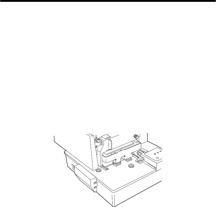
Accessing the DIP switches
The DIP switches are located inside the printer, underneath the document table.
Use the following procedure to remove the document table so you can operate
the DIP switches.
❏
Make sure that the printer is turned off and unplugged from its wall outlet.
❏
Open the printer cover.
❏
Use a Phillips head screwdriver to remove the two screws that secure the
document table in place.
3
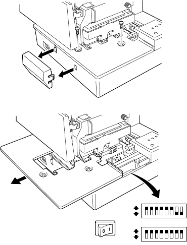
❏
Carefully work the document table loose and slide it to the left of the
printer out of the way. It is not necessary to remove the document table
complete, just move it enough so you can get at the DIP switches inside.
❏
After the document table is opened sufficiently, use a thin flat-blade
screwdriver or some other similar object to change DIP switch settings.
❏
Carefully return the document table to its original position and secure it in
place with the two screws.
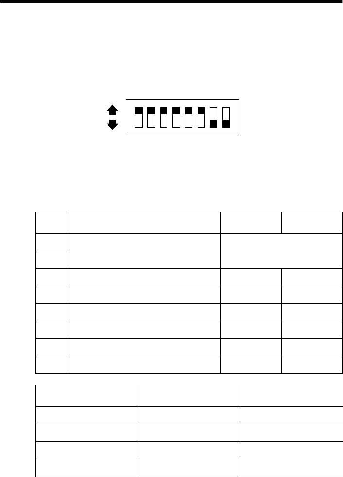
Available DIP switch settings
There are two DIP switches inside the printer, named DIP Switch 1 and DIP
Switch 2. DIP Switch 1 controls data communication parameters, while DIP
Switch 2 controls other settings.
ON
OFF
ON
OFF
4
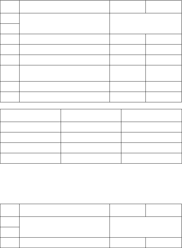
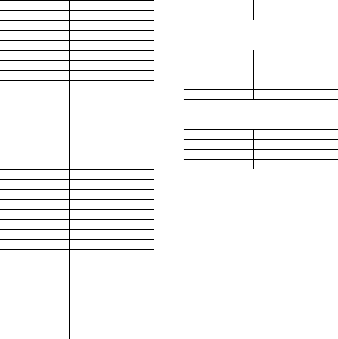
DIP Switch 1
The following table shows all the possible settings for DIP Switch 1. This
switch sets the transmission parameters of the Standard Serial Interface. All
switch settings, except for 1-7 and 1-8, are ON when the printer is shipped from
the factory.
DIP Switch 2
The following table shows all the possible settings for DIP Switch 2. The
factory default setting for this switch is all ON.
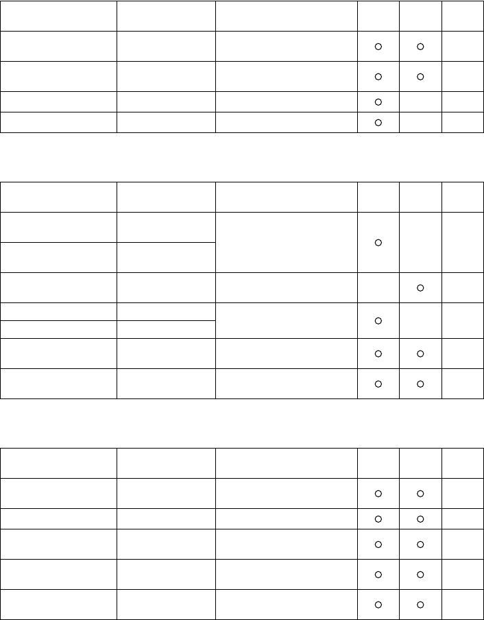
Switch Parameter ON OFF
1-1 Baud Rate See table below
1-2
1-3 Data Length 8 bits 7 bits
1-4 Parity Check Disabled Enabled
1-5 Parity Selection Odd Even
1-6 Handshake DTR/mode XON/XOFF
mode
1-7 Serial I/F Pin 6 Reset Signal Active Inactive
1-8 Serial I/F Pin8 Reset Signal Active Inactive
Baud Rate Switch 1-1 Switch 1-2
2400BPS OFF OFF
4800BPS ON OFF
9600BPS ON ON
19200BPS OFF ON
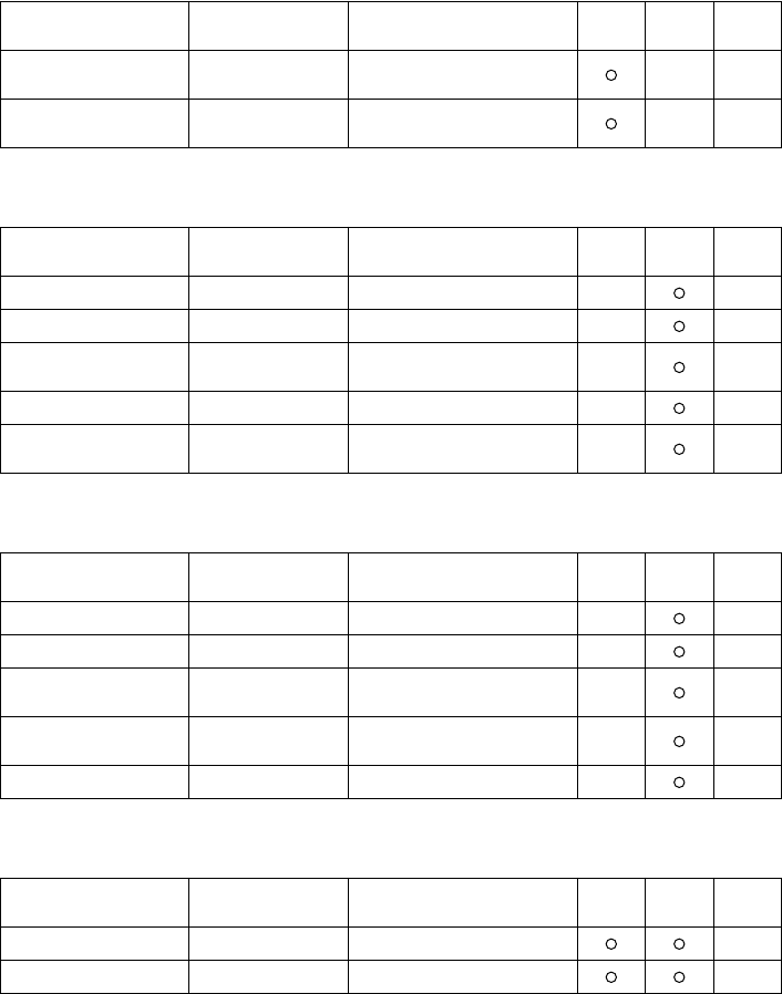
Switch Parameter ON OFF
2-1 Thermal Print Density See table below
2-2
2-3 Input Buffer Size 4 KB 45 bytes

5
2-4 Always ON
2-5 Interface Standard Option
2-6 Always ON
2-7 Not Used
2-8 Not Used
Thermal Print Density Switch 2-1 Switch 2-2
Light OFF OFF
Standard ON ON
Heavy ON OFF
Very Heavy OFF ON
Switch Parameter ON OFF
6
Chapter 3: Memory Switch Settings
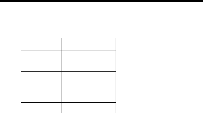
Each memory switch is a 16-bit word store in EEPROM. For details on the
functions and settings of memory switches, refer to “Chapter 9”.
The table below shows the factory settings for the memory switches.
Memory Switch Hexadecimal Code
0 0000
1 0000
2 0000
3 0000
4 0000
5 0000
7
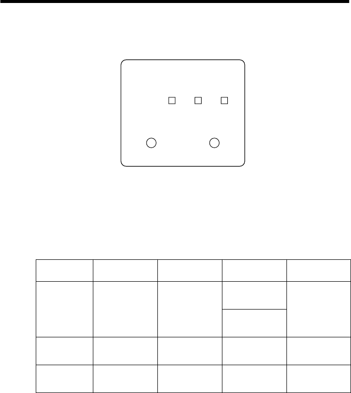
Chapter 4: Control Panel Operations
The control panel gives you some push-button control over the printer’s receipt
and slip printer operations. It also includes indicator lights, which tell you the
current status of the printer at a glance.
Indicator lights
The following table describes the meaning of indicator lights when it is on, off,
or flashing.
* All indicators flash to indicate a non-recoverable error.
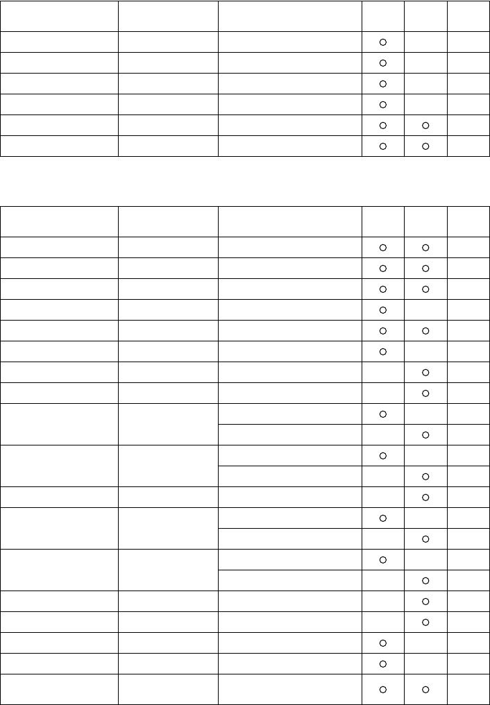
Indicator Light On Off Flashing (slow) Flashing (fast)
POWER
Power on Power off
Slip: Dot
adjustment mode Automatic
recovery Error
Receipt: Stand-by
TM-T85 macro
SLIP
Slip paper
released
Slip paper
engaged
Request
slip paper Slip printer error
RECEIPT
Receipt printer
ready
Receipt printer
not ready
Out of receipt
paper/Near end
Receipt printer
error
RECEIPT
RECEIPT SLIP POWER
SLIP/RESUME

8
Buttons
The following table describes the function of the two control buttons of the
control panel.
Producing a test print
The following procedure can be used at any time to test the receipt printer and
the slip printer.
❏
Turn on the printer and insert a piece of paper into the slip printer. Also
make sure that roll paper is loaded for the receipt printer.
Note:
If you want to produce a test print on the receipt printer only, simply don’t
insert paper into the slip printer.
❏
Turn off printer power.
❏
While holding down the
RECEIPT
button, turn printer back on. Keep
RECEIPT
depressed for a few moments until the printer beeps and the
receipt printer test print starts.
After the receipt test print is complete, the slip printer will produce a test
print on the paper you inserted in the first step of this procedure. The slip
printer test will continue until it reaches the end of the paper.
Note:
The slip printer momentarily releases the slip paper when you turn printer
power back on. If you are using a large piece of paper, it may fall out of the slip
printer when this happens, causing the slip printer test to be skipped. Because
of this, it is a good idea to keep hold of the paper in the slip printer when you
turn power back on.
Button Description
RECEIPT
Press to feed the thermal paper. Holding down this button feeds paper
at high speed.
SLIP/RESUME
1. Press this button to release or engage slip paper from the slip
printer. (Switching from releasing to engaging is only possible if
slip paper is inserted.)
2. Press this button to clear the errors of the slip printer and receipt
printer.
9
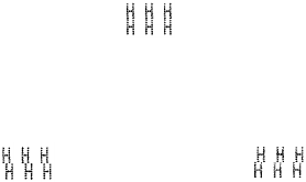
Adjusting the slip printer’s dot alignment
You may never have to use the procedure described in this section, but after you
have been using your printer for some time you may find that the dots of some
graphics do not align correctly. For example, what should look like:
may come out looking like one of the following:
This is caused when mechanical parts of the printer get out of alignment. This
happens only rarely and you may never experience it at all throughout the life
of the printer. If you do have problems, use the following procedure to correct it.
❏
Execute the test print
❏
When the slip printer produce the test print, hold down the control panel’s
RECEIPT
and
SLIP/RESUME
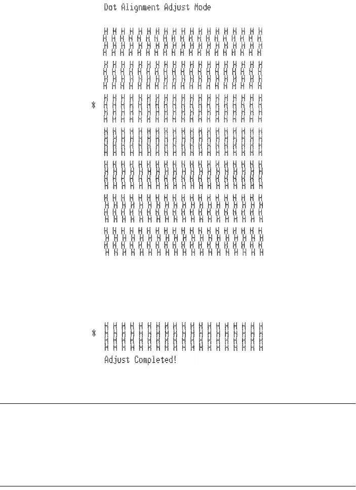
buttons, to enter the Dot Alignment
Adjust Mode. The
POWER
indicator flashes slowly to indicate this mode.
Entering the Dot Alignment Adjust Mode causes seven blocks of characters to
be printed as shown below. An asterisk to the left of the blocks indicates which
setting is currently selected. Use the
RECEIPT
button to specify which block
has the best aligned characters. Press
RECEIPT
once to specify the first block,
twice to specify the second block, and so on up to seven times to specify the
seventh block. Pressing the
RECEIPT
button more than seven times specifies
the seventh block, no matter how many times it is pressed.
or like this
10
To exit this mode, press the
SLIP/RESUME
button. The dot alignment adjust
mode setting is stored in the memory, a pattern using the selected setting,
followed by “Adjust Completed” is printed, and the printer ejects the slip paper.
Note:
If you press the
SLIP/RESUME
button without pressing the
RECEIPT
button
after entering the Dot Alignment Adjust Mode, the printer assumes that you do
not want make any settings, so it prints the message “Adjust Complete!” and
exits the mode.
If a paper feed error occurs during this mode, the printer ejects the paper and
this mode is cancelled.
11
Hexadecimal dump
This procedure prints in hexadecimal format all codes (character codes and
control codes) that are sent to the printer by the computer. The printer does not
execute any control codes (such as 0A - linefeed), it just prints them out. The
hexadecimal dump is useful when you are writing programs for printer control.
❏
Make sure that roll paper is loaded in the receipt printer.
❏
Turn off the printer.
❏
While holding down the control panel’s
SLIP/RESUME
button, turn the
printer back on to enter this mode. The printer beeps once to indicate in this
mode.
❏
The printer will now print out the hexadecimal values of any data that is
subsequently sent to it from your computer. The last line buffer should be
flushed by pressing the
RECEIPT
button.
❏
To exit this mode, turn the printer off.
Errors
There are three types of errors:
automatic recovery
errors that clear
automatically after some condition is attained,
recoverable
errors that require
some action by you before they clear, and
non-recoverable
errors that require
servicing by an authorized dealer. If a slip printer error occurs, the
SLIP
indicator flashes quickly. If a receipt printer error occurs, the
RECEIPT
indicator flashes quickly.
Automatic Recovery Error
Error Name Cause POWER
Flashing Pattern Recovery
Head Temperature Error Abnormal thermal head
temperature
Fast Recovery occurs automatically after
head temperature returns to normal.

12
Receipt Printer Recoverable Errors
Slip Printer Recoverable Errors
Non-recoverable Errors
First try turning the printer off and then on again. If the error persists or if a non-
recoverable error is indicated by all indicators flashing, contact your nearest
authorized dealer.
Error Name Cause RECEIPT
Flashing Pattern Recovery
Paper Out Error No roll paper Slow Insert paper and press SLIP/RESUME.
Head Up Error Raised receipt printer
head
Fast Lower head and press SLIP/RESUME.
Near End Roll paper near end Slow Press SLIP/RESUME to resume
printing.
Cutter Error Error during roll paper
cutting
Fast If the blade is in the home position,
press SLIP/RESUME to continue
printing. If the blade is not in the home
position, this is a non-recoverable error.
Error Name Cause SLIP
Flashing Pattern Recovery
Slip printer mechanism
error
• Carriage motor lock
• Timing signal defect
• Abnormal home
position check
Fast Correct the problem and press SLIP/
RESUME.
13
Chapter 5: Standard Serial Interface
❏
This chapter provides detailed specifications for the printer’s standard serial
interface (Connector Type: D-sub 9-pin).
Set the transmission parameters with DIP Switch 1.
Transmission type............Asynchronous serial interface
Baud rate (bps).................2400, 4800, 9600, or 19200
(Selected by DIP switch)
Word format
Start bit:................1
Data bits: ..............7 or 8 (Selected by DIP switch)
Parity: ...................Odd, Even, or None
(Selected by DIP switch)
Stop bit: ................1
Signal polarities
RS-232C...............Mark = Logic “1” (–3V to –15V)
Space = Logic “0” (+3V to +15V)
Handshaking ....................DTR or XON/XOFF mode (Selected by DIP switch)
Input (RXD, DSR, INIT)
Output (DTR, TXD, RTS)
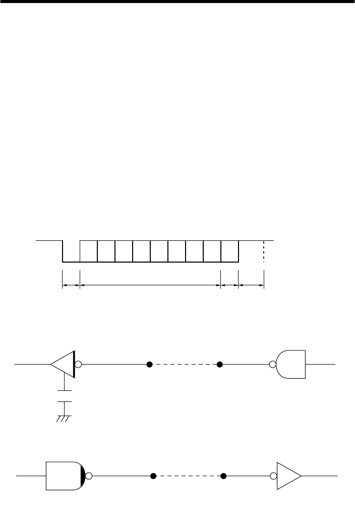
b0 b1 b2 b3 b4 b5 b6 (b7)
ABCD
Mark [1]
Space [0]
A: Start bit
B: Data bits
C: Vertical parity bit
D: Stop bit
Printer Host computer
75188 or equivalent
Printer Host computer
14
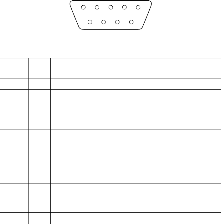
Standard serial interface pins and signal names
Pin
No. Signal
Name Direction Function
1 FG — Frame Ground
2 RXD IN Receive data
3 TXD OUT Transmission data
4 DTR OUT Data terminal ready signal. This signal changes to SPACE when the printer is ready to
receive data.
5 SG — Signal ground
6 DSR IN Signal line that indicates if the host computer can receive data.
SPACE: host can receive
MARK: host cannot receive
The status of this signal is not confirmed.
This signal can be specified as an internal reset signal using Switch 7 of DIP Switch 1
(page 4). MARK of 1ms or longer activates the reset.
7 RTS OUT Same as DTR (Pin 4).
8 INIT IN This signal can be specified as an internal reset signal using Switch 8 of DIP Switch 1
(page 4). SPACE of 1ms or longer activates the reset.
9 N/C — Not connected
51
6
9
15
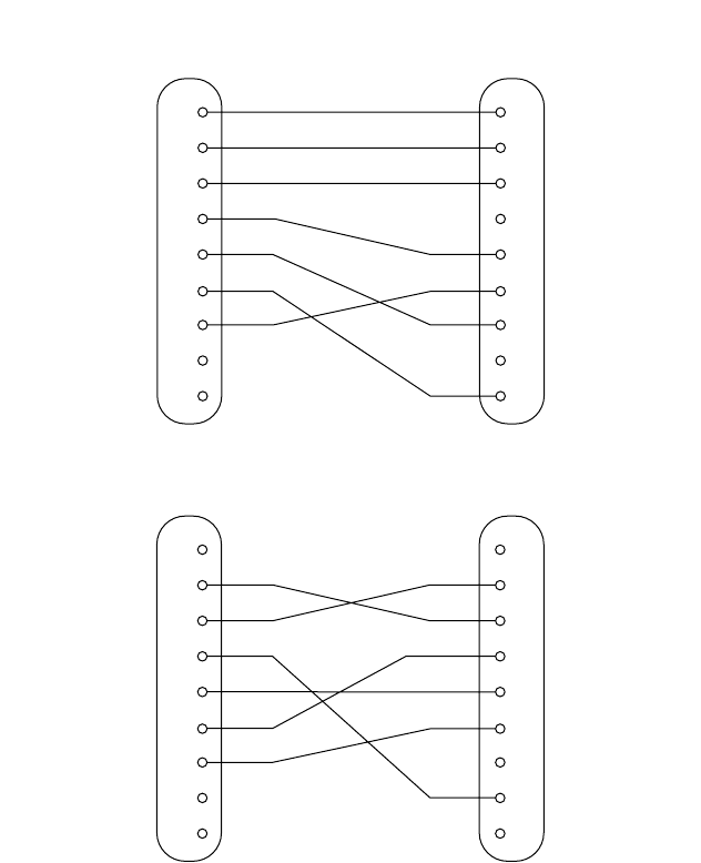
Interface connections
❏
Refer to the interface specifications for the host computer for details on
connecting to its interface connector. The following illustration shows a
typical connection configuration.
RS-232C
1
2
3
4
5
7
8
9
1
2
3
4
5
6
7
8
20
F-GND
TXD
RXD
RTS
CTS
DSR
S-GND
DCD
DTR
F-GND
RXD
TXD
DTR
S-GND
6DSR
RTS
INIT
N/C
Printer side
(D-sub 9 pin) IBM PC side
(D-sub 25 pin)
1
2
3
4
5
7
8
9
1
2
3
4
5
6
7
8
9
DCD
RXD
TXD
DTR
S-GND
DSR
RTS
CTS
RI
F-GND
RXD
TXD
DTR
S-GND
6DSR
RTS
INIT
N/C
Printer side
(D-sub 9 pin) IBM PC side
(D-sub 9 pin)
16
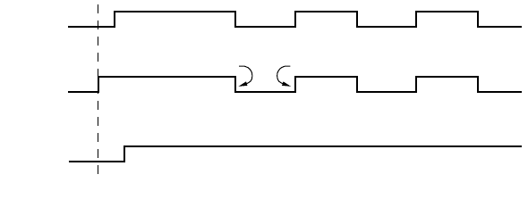
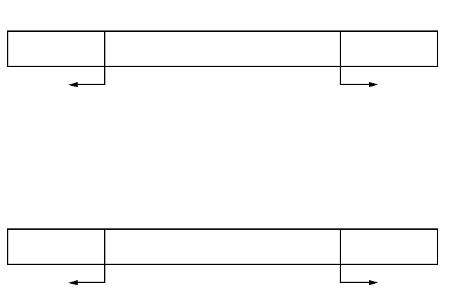
Data protocol
❏
DTR/DSR Mode
Set when dip switch #1-6 is ON. Communication is carried out while handshake
is performed with the DTR and DSR signals. Control is executed by selecting
the DTR signal for the busy signal when data is downloaded to the printer data.
“SPACE” indicates the printer can receive data, and oppositely “MARK”
indicates that data cannot be received.
In the ESC/POS mode, control is executed by selecting the DTR signal for the
host computer’s busy signal when data is uploaded from the printer. “SPACE”
indicates the host can receive data, and oppositely “MARK” indicates that data
cannot be received.
If no error occurs for the printer after turning the power on, the DTR signal line
is set to “SPACE.” After the host computer recognizes that the DTR signal line
is “SPACE,” data text is sent to the RXD signal line. When the printer’s
available buffer space drops below the specified number of bytes (256 bytes if
using 4K-byte reception buffer, 16 bytes if using a 45-byte reception buffer; see
3-2 for details), the DTR signal line is set to “MARK.” After the host computer
recognizes that the DTR signal line is “MARK,” data text transmission is
interrupted, but the printer can receive data up until the data buffer becomes full.
Available space in the data buffer increases as printing is executed, and when
the printer’s available buffer space drops below the specified number of bytes
(256 bytes if using 4K-byte reception buffer, 16 bytes if using a 45-byte
reception buffer), the DTR signal line is set to “SPACE.”
In the ESC/POS mode, printer status transmission can be received by the host
in the DTR/DSR communication mode (status is set after the DSR signal is
confirmed as being “SPACE,” with the exception of some status transmission
commands).
RXD
DTR
Data Data Data
Buffer full Buffer empty
Printing
Power ON
17
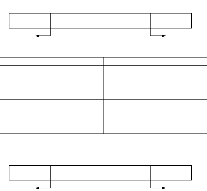
Buffer full cancellation in DTR mode (the following is an example in the
Combination mode).
A) Buffer set to “big size” (4K-bytes) (set with dip switch 2-3)
When available space drops below 256 bytes, DTR is set to “MARK.” When
data in the buffer drops below 256 bytes, DTR is set to “SPACE.”
B) Buffer set to “small size” (45-bytes) (set with dip switch 2-3)
When available space drops below 16 bytes, DTR is set to “MARK.” When data
in the buffer drops below 16 bytes, DTR is set to “SPACE.”
Data buffer
Full Near Full
Near Empty Empty
DTR “MARK” DTR “SPACE”
Remainder
256 bytes 256 bytes
Data buffer
Full Near Full
Near Empty Empty
DTR “MARK” DTR “SPACE”
Remainder
16 bytes 16 bytes
18
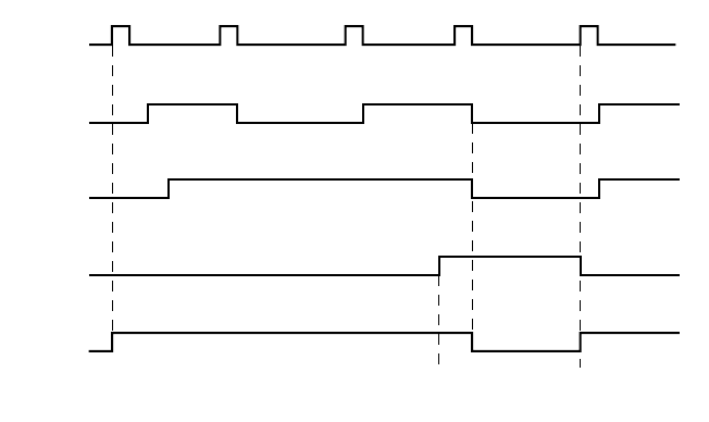
❏
X-ON / X-OFF Mode
Set when dip switch #1-6 is OFF. Mode whereby the host is informed by TXD
signal of X-ON (DC1) when data can be received or X-OFF (DC3) when data
cannot be received. In the Star mode, X-ON / X-OFF output timing conditions
are set by memory switch 4-C.
In the Combination mode, when memory switch 4-C is set to “0” (factory
setting), exactly one byte is output for X-ON when the printer switches from
offline (printer busy) to online (printer ready), and exactly one byte is output for
X-OFF when the printer switches from online (printer ready) to offline (printer
busy). The same goes for the ESC/POS mode (Dual mode), regardless of the
setting of memory switch C-4. When memory switch C-4 is set to “1,” the X-
ON signal is output is every three seconds.
If no error occurs for the printer after turning the power on, the X-ON signal
(“DC1” by control code name, “11H” by hexadecimal data) is output by the
TXD signal line. X-FF (DC3, 13H) is output when available buffer space drops
below the specified number of bytes (256 bytes if using 4K-byte reception
buffer, 16 bytes if using a 45-byte reception buffer). If memory switch 4C is set
to “1,” an X-OFF signal is output each time one byte of data is received. The
host computer receiving the X-0FF signals interrupts data text transmission, but
the printer can receive data up until the data buffer becomes full. If the amount
of data sent exceeds the amount of available buffer space, the excess data is
discarded. Available space in the data buffer increases as printing is executed,
and the X-ON signal is output when the printer's available buffer space drops
below the specified number of bytes (256 bytes if using 4K-byte reception
buffer, 16 bytes if using a 45-byte reception buffer).
TXD
RXD
ON
OFF
X–ON X–OFF X–ON X–OFF X–ON
Printing
Paper out
signal
ON LINE
lamp
Data Data Data
Paper out
Power ON Load paper and press
the ON LINE switch.
19
Buffer full cancellation in X-ON / X-OFF mode (the following is an example in
the Combination mode).
A) Buffer set to “big size” (4K-bytes) (set with sip switch 2-3)
B) Buffer set to “big size” (45-bytes) (set with sip switch 2-3)
Printer setting conditions Description of operation
• When in Star mode and memory switch
is set to “0”
• ESC/POS emulation
When available buffer space drops below
256 bytes, exactly one byte is output for
X-OFF. When data in the buffer drops
below 256 bytes, exactly one byte is
output for X-ON.
• When in Star mode and memory switch
is set to “1” When available buffer space drops below
256 bytes, an X-OFF signal is output for
each byte of data received. When data in
the buffer drops below 256 bytes, and X-
ON signal is output.
Data buffer
Full Near Full
Near Empty Empty
X-OFF X-ON
Remainder
256 bytes 256 bytes
Data buffer
Full Near Full
Near Empty Empty
X-OFF X-ON
Remainder
16 bytes 16 bytes

20
3-6) X-ON / X-OFF Signal Transmission Timing
An X-OFF signal is sent when the printer switches from online to offline.
An X-ON signal is sent when the printer switches from offline to online.
In the Star mode, an X-ON signal is sent every three seconds if memory switch
4-C is set to “1.”
4) Suggestions when memory switch 4-4 is ON [only when using interface specially
designed for for ESC/POS (Dual mode)]
(1) Printing is interrupted in the event of an error, the cover is open, there is no paper,
or paper is advanced by the paper advance switch, but the printer does not switch
to busy status.
(2) When handshake with the printer is executed by this setting, be sure to monitor
the status of the printer using the “GS a” command and its automatic data
transmission function. With this setting, the “GS a” command becomes initial
value setting n = 2, and status is automatically transmitted when online/offline
status changes.
(3) If using DLE EOT or DLE ENQ, do not allow the reception buffer to become full.
• Suggestions when the printer is busy and the host cannot transmit data DLE
EOT or DLE ENQ cannot be used if an error occurs when the printer becomes
busy because the reception buffer is full.
• Suggestions when the printer is busy and the host can transmit data
When the reception buffer becomes full during transmission of bit image data,
if a DLE EOT or DLE ENQ command is used in the bit image data, DLE EOT
or DLE ENQ is processed as bit image data. Data sent when the reception
buffer is full may be discarded.
Usage Example: With a 4K-byte reception buffer, status is checked by “ESC v”
or “ESC u” each time a printing line is sent. The amount of data per printing line
is the amount whereby the reception buffer does not become full.
Printer setting conditions Description of operation
• When in Star mode and memory switch
is set to “0”
• ESC/POS emulation
When available buffer space drops below
256 bytes, exactly one byte is output for
X-OFF. When data in the buffer drops
below 256 bytes, exactly one byte is
output for X-ON.
• When in Star mode and memory switch
is set to “1” When available buffer space drops below
256 bytes, an X-OFF signal is output for
each byte of data received. When data in
the buffer drops below 256 bytes, and X-
ON signal is output.
21
Chapter 6: Optional Interface
Optional serial interface
Use a thin flat-blade screwdriver or some other similar object to change DIP
switch settings on the optional serial interface board.
The following table shows all the possible settings for the DIP switches. All
switch settings, except for 1-7 and 1-8, are ON when the printer is shipped from
the factory.
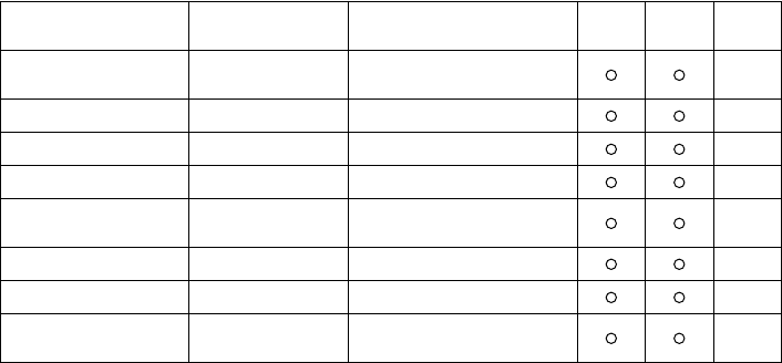
Switch Parameter ON OFF
1Baud Rate See table below
2
3 Data Length 8 bits 7 bits
4 Parity Check Disabled Enabled
5 Parity Selection Odd Even
6 Handshake DTR/DSR XON/XOFF
7 Serial I/F Pin 6 Reset Signal Active Inactive
8 Serial I/F Pin 25 Reset Signal Active Inactive
Baud Rate Switch 1 Switch 2
2400BPS OFF OFF
4800BPS ON OFF
9600BPS ON ON
19200BPS OFF ON
ON
OFF 12345678
22
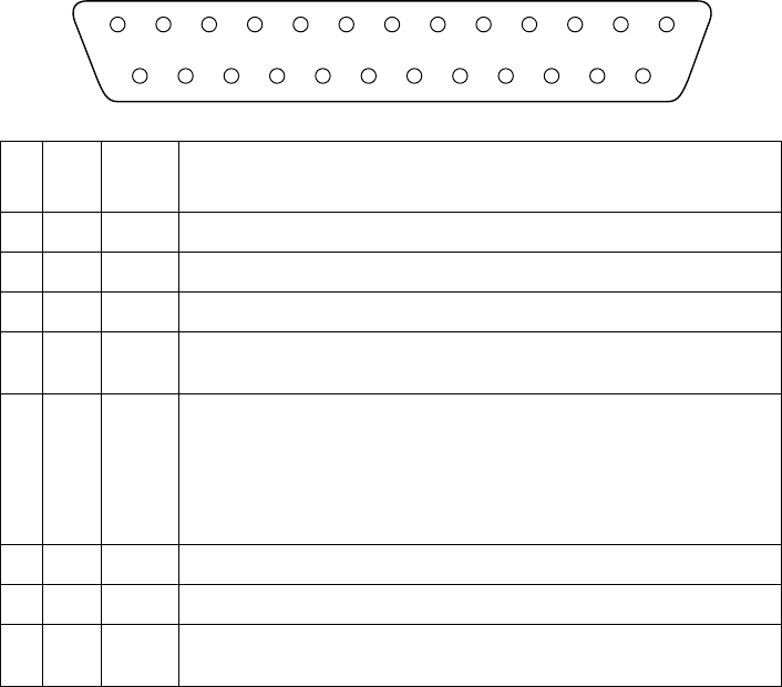
Optional serial interface pins and signal names
Pin
No. Signal
Name Direction Function
1 FG — Frame Ground
2 TXD OUT Transmission data
3 RXD IN Receive data
4 RTS OUT Data terminal ready signal. This signal changes to SPACE when the printer is ready to
receive data.
6 DSR IN Signal line that indicates if the host computer can receive data.
SPACE: host can receive
MARK: host cannot receive
The status of this signal is not confirmed.
This signal can be specified as an internal reset signal using of DIP Switch 7 (page 21).
MARK of 1ms or longer activates the reset.
7 SG — Signal ground
20 DTR OUT Same as RTS (Pin 4).
25 INIT IN This signal can be specified as an internal reset signal using of DIP Switch 8 (page 21).
SPACE of 1ms or longer activates the reset.
13
25
1
14
23
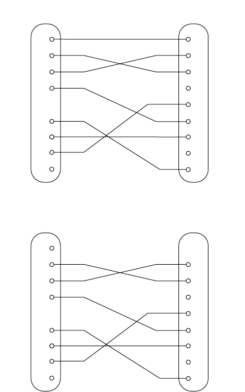
Interface connections
❏
Refer to the interface specifications for the host computer for details on
connecting to is its interface connector. The following illustration shows a
typical connection configuration.
Data protocol
❏
The specifications for the DTR and X-ON/X-OFF modes are the same as
for the Standard Serial Interface.
1
2
3
4
6
1
2
3
4
5
6
7
8
20
F-GND
TXD
RXD
RTS
DSR
20
25
7
S-GND
DTR
INIT
Printer side
(D-sub 25 pin) IBM PC side
(D-sub 25 pin)
F-GND
TXD
RXD
RTS
CTS
DSR
S-GND
DCD
DTR
1
2
3
4
6
3
2
7
8
6
5
1
4
F-GND
TXD
RXD
RTS
DSR
20
25
7
S-GND
DTR
INIT
Printer side
(D-sub 25 pin) IBM PC side
(D-sub 9 pin)
F-GND
TXD
RXD
RTS
CTS
DSR
S-GND
DCD
DTR
24
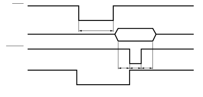
Optional parallel interface
Interface: Conforms with Centronics parallel interface standard
Data transfer speed: 1000 ~ 5000 CPS
Synchronization: External strobe pulse
Handshaking: Using ACK and BUSY
Logic level: TTL-level compatible
TTT
A C K
DATA
STROBE
BUSY
T: At least 0.5µs
Approx. 9µs
25
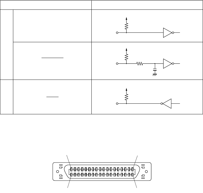
Optional parallel interface pins and signal names
Signal Name Sample Circuit
Input
DATA 1
DATA 8
STROBE
Output
BUSY
ACK
4.7kΩ
74LS-equivalent
1kΩ
100Ω
1000pF
74LS-equivalent
1.8kΩ
74LS-equivalent
(18) (1)
(36) (19)

26
Pin
No. Signal Name Direction Function
1 STROBE IN Signals when data is ready to be read. Signal goes from HIGH to LOW (for at
least 0.5
µ
s) when data is available.
2 - 9 DATA 1 - 8 IN Information on the first eight bits of parallel data. Each signal is HIGH for logical
1 and LOW for logical 0.
10 ACK OUT 9
µ
s LOW pulse to acknowledge receipt of data
11 BUSY OUT Printer is ready to receive data when LOW. HIGH indicates one of the following
conditions.
• Data being entered
• Printer off line
• Error condition
12 PAPER OUT OUT Normally LOW, this signal goes HIGH when the printer is out of paper.
13 SELECTED OUT HIGH when the printer is on line
14 — IN This signal is not checked by printer.
15 N/C — Not connected
16 SIGNAL GND — Signal ground
17 CHASSIS GND — Chassis ground (isolated from logic ground)
18 +5VDC — +5V DC (max. 50mA)
19 - 30 GND — Twisted pair return signal ground level
31 RESET IN LOW when printer is reset to power-on defaults
32 ERROR OUT Normally HIGH, this signal goes LOW to signal that printing is disabled due to an
error condition.
33 EXT GND — External ground
34 - 35 N/C — Not connected
36 — IN This signal is not checked by printer.
27
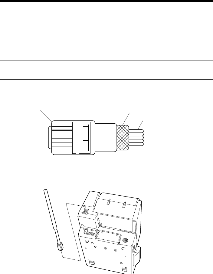
Chapter 7: Peripheral Unit Driver Circuit
The main logic board of this printer includes a circuit for driving peripheral
units, such as cash drawers. A modular connector for connection of the
peripheral unit is located on the back of the printer. To connect to the drive
circuit, connect the peripheral unit to the modular connector using a cable
supplied by you that meets the following specifications.
• Use a cable with a modular plug like that one shown in the figure below.
Important!
Never connect any other type of plug to the peripheral unit connector.
Modular plug
16
Modular plug: MOLEX 90075-0007,
AMP641337, or JAPAN BURNDY B-66-4 Shield
Wire lead
1 loop
Ferrite core
28
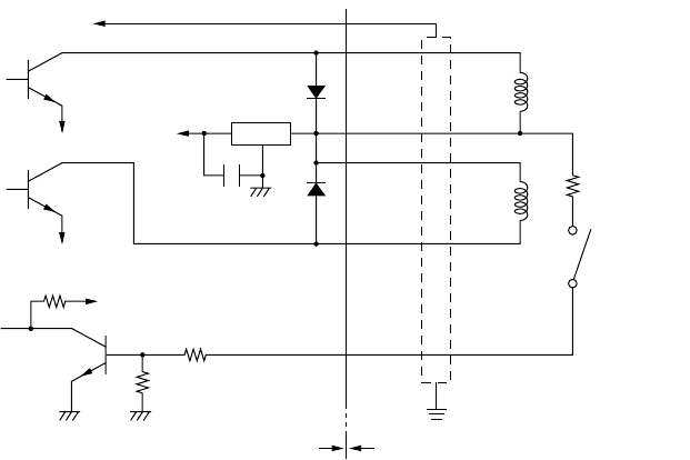
Drive circuit
The recommended drive unit is shown below.
[Drive output 24V, max. 1.0A]
Notes
• Peripheral Units 1 and 2 cannot be driven simultaneously.
• For continuous driving, do not use drive duty above 20%.
• Compulsion switch status is available as status data.
• Minimum resistance for coils L1 and L2 is 24
Ω
.
• Absolute maximum ratings for diodes D1 and D2 (Ta = 25
°
C) are:
Average Rectified Current Io = 1A
Maximum forward surge current (60Hz, 1-cycle sine wave) I
FSM
= 40A
• Absolute maximum rating for transistors TR1 and TR2 (Ta = 25
°
C) are:
Collector current Ic = 2A
7824
F.G
TR1
M-GND
TR2
M-GND
TR3
+5V
+24V
R1
R2
6
5
4
3
2
1
L1
L2
R3
4.7kΩ
1/4W
Frame
ground
Printer side User side
D1
D2
Peripheral
unit 1
With shield
Peripheral
unit 2 Compulsion
switch

29
Chapter 8: Automatic Cutter
1
The cutter operates in response to data commands. To enable cutter
operation, set Memory Switch #2-8 to indicate that the cutter is installed.
2
NEVER place fingers or metal objects in the cutter area.
3
If a jam occurs in the cutter area, switch off the power, use tweezers to
remove the jammed paper, then switch the power back on. The printer will
return the blade to the home position.
4
Never clean the cutter blade with alcohol or any other solvent, as this may
remove the blade’s lubrication and shorten the blade life.
30
Chapter 9: Control Codes
Important!
Please access the following URL
http://www.star-micronics.co.jp/service/sp_sup_e.htm
for the lastest revision of the manual.
This printer has two command modes: Star mode and ESC/POS mode.
The Star mode emulates thermal receipt printers such as the TSP200 series and
other previous models. The ESC/POS mode emulates the Epson TM-T85
receipt printer and the Epson TM-295 slip printer.
The Star mode commands are as follows.
Print Station Selection (Combo mode only)
Character Selection
Control codes Hexadecimal codes Function Receipt-
printer Slip
printer Page
<ESC> “+” “A” 0
<ESC> “+” “A” <0> 1B 2B 41 30
1B 2B 41 00 Select receipt printer 36
<ESC> “+” “A” 3
<ESC> “+” “A” <3> 1B 2B 41 33
1B 2B 41 03 Select slip printer 36
Control codes Hexadecimal codes Function Receipt-
printer Slip
printer Page
<ESC> “R”
n
1B 52
n
Select international character
set 36
<ESC> “/”
“1”
<ESC> “/”
<1> 1B 2F 31
1B 2F 01 Select slash zero 36
<ESC> “/”
“0”
<ESC> “/”
<0> 1B 2F 30
1B 2F 00 Select normal zero 36
<ESC> “b”
n1 n2 n3 n4
d1
... <RS> 1B 62
n1 n2 n3 n4
d1 ...
1E Select bar code printing 37
<ESC> “M” 1B 4D Select 12-dot pitch printing 41
Select 7
×
9 (half dot) font 41
<ESC> “p” 1B 70 Select 14-dot pitch printing 41
<ESC> “P” 1B 50
Select 15-dot pitch printing 41
Select 5
×
9 (2 pulses = 1 dot)
font 41
31
<ESC> “:” 1B 3A
Select 16-dot pitch printing 41
Select 5
×
9 (3 pulses = 1 dot)
font 41
<ESC> <SP>
n
1B 20
n
Set character spacing 41
<SO> 0E Set the printing magnified
double in character width. 42
<DC4> 14 Resets the printing magnified
in character width. 42
<ESC> “W”
n
1B 57
n
Set the magnification rate in
character width. 42
<ESC> <SO> 1B 0E Sets the printing magnified
double in character width. 42
<ESC> <DC4> 1B 14 Resets the printing magnified
in character width. 42
<ESC> “h”
n1B 68 nSets the magnification rate in
character height. 43
<ESC> “i” n1 n2 1B 69 n1 n2 Sets the magnification rates
in character width and height. 43
<ESC> “–” “1”
<ESC> “–” <1> 1B 2D 31
1B 2D 01 Select underlining 43
<ESC> “–” “0”
<ESC> “–” <0> 1B 2D 30
1B 2D 00 Cancel underlining 43
<ESC> “_” “1”
<ESC> “_” <1> 1B 5F 31
1B 5F 01 Select upperlining 44
<ESC> “_” “0”
<ESC> “_” <0> 1B 5F 30
1B 5F 00 Cancel upperlining 44
<ESC> “4” 1B 34 Select highlight printing 44
<ESC> “5” 1B 35 Cancel highlight printing 44
<SI> 0F Inverted printing 44
<DC2> 12 Cancel inverted printing 44
<ESC> “E” 1B 45 Select emphasized printing 45
<ESC> “F” 1B 46 Cancel emphasized printing 45
<ESC> “U” “1”
<ESC> “U” <1> 1B 55 31
1B 55 01 Select uni-directional
printing 45
<ESC> “U” “0”
<ESC> “U” <0> 1B 55 30
1B 55 00 Select bi-directional printing 45
Control codes Hexadecimal codes Function Receipt-
printer Slip
printer Page
32
Page Formatting
Print Position Control
Control codes Hexadecimal codes Function Receipt-
printer Slip
printer Page
<ESC> “C” n1B 43 nSet page length in lines 46
<ESC> “C” <0> n1B 43 00 nSet page length in inches 46
<ESC> “N” n1B 4E nSet bottom margin 46
<ESC> “O” 1B 4F Cancel bottom margin 46
<ESC> “1” n1B 6C nSet left margin 47
<ESC> “Q” n1B 51 nSet right margin 47
Control codes Hexadecimal codes Function Receipt-
printer Slip
printer Page
<LF> 0A Line feed 48
<CR> 0D Carriage Return 48
<ESC> “a” n1B 61 n Feed paper n lines 48
<FF> 0C Form feed 48
<HT> 09 Horizontal tab 48
<VT> 0B Vertical tab 49
<ESC> “A” n1B 41 nDefine n/72-inch line spacing 49
<ESC> “2” 1B 32 Set line spacing to n/72-inch 49
<ESC> “z” “1”
<ESC> “z” <1> 1B 7A 31
1B 7A 01
Set line spacing to 4 mm 49
Set line spacing to 1/6-inch 49
<ESC> “0” 1B 30 Set line spacing to 3 mm 50
Set line spacing to 1/8-inch 50
<ESC> “1” 1B 31 Set line spacing to 7/72-inch 50
<ESC> “J” n1B 4A nOne time n/4 mm feed 50
One time n/72-inch feed 50
<ESC> “j” n1B 6A nOne time n/4 mm backfeed 51
One time n/72-inch backfeed 51
<ESC> “3” n1B 33 nSet line spacing to n/216-inch 51
<ESC> “y” n1B 79 nSet line spacing to n/144-inch 51
<ESC> “I” n1B 49 nOne time n/8-mm feed 51
<ESC> “B” n1 n2 ... <0> 1B 42 n1 n2 ... 00 Set vertical tab stops 52
<ESC> “D” n1 n2 ...
<0> 1B 44 n1 n2 ... 00 Set horizontal tab stops 52
33
Dot Graphics Printing
Download Graphics Printing
Peripheral Device Control
Control codes Hexadecimal codes Function Receipt-
printer Slip
printer Page
<ESC> “K” n <0>
m1 m2 ... 1B 4B n 00 m1 m2
... Print normal density graphics 53
<ESC> “L” n1 n2
m1 m2 ... 1B 4C n1 n2 m1 m2
... Print high density graphics 56
<ESC> “k” n <0> m1 ... 1B 6B n 00 m1 ... Print fine density graphics 58
<ESC> “X” n1n2 m1 ... 1B 58 n1n2 m1... Print fine density graphics 61
Control codes Hexadecimal codes Function Receipt-
printer Slip
printer Page
<ESC> “&” “1” “1”
n m1 m2 ... m48 1B 26 31 31 n
m1 m2 ... m48 Define download character
(12 × 24 dot font) 62
<ESC> “&” <1> <1>
n m1 m2 ... m48 1B 26 01 01
n m1 m2 ... m48
<ESC> “&” <0> n1 n2 1B 26 00 n1 n2 Define download character
(7 × 9, 5 × 9 dot font) 65
<ESC> “&” “1” “0” n1B 26 31 30 nDelete a download character
(12 × 24 dot font) 65
<ESC> “&” <1> <0> n1B 26 01 00 n
<ESC> “%” “1”
<ESC> “%” <1> 1B 25 31
1B 25 01 Enable download character
set 65
<ESC> “%” “0”
<ESC> “%” <0> 1B 25 30
1B 25 00 Disable download character
set 65
Control codes Hexadecimal codes Function Receipt-
printer Slip
printer Page
<ESC> <BEL> n1 n2 1B 07 n1 n2 Define drive pulse width for
peripheral device #1 66
<BEL> 07 Control peripheral device #1 66
<FS> 1C Control peripheral device #1
immediately 66
<EM> 19 Control peripheral device #2
immediately 66
<SUB> 1A Control peripheral device #2
immediately 66
34
Auto Cutter Control
Slip Printer Control
Page Mode
Customer Display Commands (Combo mode only)
Control codes Hexadecimal codes Function Receipt-
printer Slip
printer Page
<ESC> “d” “0”
<ESC> “d” <0> 1B 64 30
1B 64 00 Full-cut command to the auto
cutter 67
<ESC> “d” “1”
<ESC> “d” <1> 1B 64 31
1B 64 01 Partial-cut command to the
auto cutter 67
Control codes Hexadecimal codes Function Receipt-
printer Slip
printer Page
<ESC> <SI> n 1B 0F nSetting slip sensor 68
<ESC> <FF> n1B 0C nSlip function 68
<ESC> <VT> m n 1B 0B m n Set the paper eject direction/
length 69
<EOT> 04 Slip status enquiry 69
<ESC> <EM> n m
<LF> <NUL> 1B 19 n m 0A 00 Set the wait time until the
automatic clamp is activated 70
Control codes Hexadecimal codes Function Receipt-
printer Slip
printer Page
<ESC> “n”1B 6E Select page mode 70
<ESC> “!” 1B 21 Select line mode 71
<ESC> “*” ... 1B 2A ... Setting print area in page
mode 72
<ESC> “T” n1B 54 nSetting print direction in page
mode 73
<FF> 0C Print in page mode 74
Control codes Hexadecimal codes Function Receipt-
printer Slip
printer Page
<ESC> “S” 1B 53 Start customer display 75
<ESC> “G” 1B 47 End customer display 75
35
Other Commands
Control codes Hexadecimal codes Function Receipt-
printer Slip
printer Page
<CAN> 18 Cancel printer buffer &
Initialize printer 76
<DC3> 13 Deselect printer 76
<DC1> 11 Set select mode 76
<RS> 1E Beep the buzzer 76
<ESC> “#N, n1 n2 n3 n4”
<LF> <NUL> 1B 23 N 2C n1 n2 n3 n4
0A 00 Set memory switch 77
<ESC> “@” 1B 40 Initialize printer 80
<ENQ> 05 Enquiry 80
<ESC> “?” <LF> <NUL> 1B 3F 0A 00 Reset printer hardware and
produce a test print. 83
36
Printer Station Selection (Combo mode only)
<ESC> “+” “A” n
1B 2B 41 n
Print Station Selection
n = 0, “0” : Selects the receipt printer
3, “3” : Selects the slip printer
This command is only valid when it entered at the beginning of a
line. If this command is not set at the beginning of a line, the printer
will ignore the command and continue to print on previously selected
print station.
Character Selection
<ESC> “R” n
1B 52 n
Select international character set
Selects an international character set according to the value of n, as
shown below:
0 n 12, “0” n “9”, “A” n “C”
n = 0, “0” : U.S.A. 1, “1” : France 2, “2” : Germany
3, “3” : England 4, “4” : Denmark 1 5, “5” : Sweden
6, “6” : Italy 7, “7” : Spain 1 8, “8” : Japan
9, “9” : Norway 10, “A” : Denmark 2 11, “B” : Spain 2
12, “C” : Latin America
Although the international character set can also be selected using a
memory switch, the control code setting is given priority.
<ESC> “/” n
1B 2F n
Select zero style
Causes subsequent zero characters to be printed with a slash when n
is 1, and without a slash when n is 0.
The valve of n can be set to 0(00H) or “0”(30H), or 1(0H) or
“1”(31H).
The default may differ depending on the memory switch setting.
CODE
HEX
FUNCTION
CODE
HEX
FUNCTION
≤ ≤ ≤ ≤ ≤ ≤
CODE
HEX
FUNCTION

37
<ESC> “b” n1 n2 n3 n4 d1 ... dk <RS>
1B 62 n1 n2 n3 n4 d1 ... dk 1E
Select bar code printing
Prints bar code according to the value of n1, as shown below:
This command is only valid with the receipt printer.
n1: Type of bar code
0 UPC-E
1 UPC-A
2 JAN/EAN-8
3 JAN/EAN-13
4 CODE 39
5 ITF
6 CODE 128
7 CODE 93
8 NW-7
The value of n1 can be set to 0(00H) or 8(08H) or “0”(30H) to
“8”(38H).
n2: Printing character below bar code or line feed
1 Character below bar code is not printed, Line feed is
performed after execution of command.
2 Character below bar code is printed, Line feed is
performed after execution of command.
3 Character below bar code is not printed, Line feed is
not performed after execution of command.
4 Character below bar code is printed, Line feed is not
performed after execution of command.
The value of n2 can be set to 1(01H) to 4(04H) or “1”(31H) to
“4”(34H).
n3: Mode of bar code
UPC-E, UPC-A, JAN/EAN-8, JAN/EAN-13, CODE 128,
CODE 93
1 Minimum module 2 dots
2 Minimum module 3 dots
3 Minimum module 4 dots
CODE
HEX
FUNCTION
38
CODE 39, NW-7, ITF
When the value of n3 is UPC-E, UPC-A, JAN/EAN-8, JAN/EAN-
13, CODE 128 or CODE 93, 1(01H) to 3(03H) or “1”(31H) to
“3”(33H) can be set. When the value of n3 is CODE39, NW-7 or
ITF, 1(01H) to 9(09H) or “1”(31H) to “9”(39H) can be set.
n4: Height of bar code
Can be up to 255 dots (31.9 mm).
If the bar code height is larger than the line feed amount, the line
feed amount is automatically multiplied by an integer.
d1...dk: Bar code data
UPC-E/UPC-A: K = 11 (or 12)
The check digit at the 12th digit is automatically added,
and ignored even if it is specified.
JAN/EAN-8: K = 7 (or 8)
The check digit at the 8th digit is automatically added, and
ignored even if it is specified.
JAN/EAN-13: K = 12 (or 13)
The check digit at the 13th digit is automatically added,
and ignored even if it is specified.
CODE39: The value of k is optional, and the maximum
value also differs according to the modes (21
digits maximum in mode 7).
The start/stop code (“*”) is automatically added.
CODE 39, NW-7 ITF
1 Narrow : wide 2:6 dots 2:5 dots
2 Narrow : wide 3:9 dots 4:10 dots
3 Narrow : wide 4:12 dots 6:15 dots
4 Narrow : wide 2:5 dots 2:4 dots
5 Narrow : wide 3:8 dots 4:8 dots
6 Narrow : wide 4:10 dots 6:12 dots
7 Narrow : wide 2:4 dots 2:6 dots
8 Narrow : wide 3:6 dots 3:9 dots
9 Narrow : wide 4:8 dots 4:12 dots
39
ITF The value of k is optional, and the maximum
value also differs according to the modes (40
digits maximum in mode 4).
If the data is number of an odd digits, 0 is
automatically added at the beginning of the data.
CODE 128: The value of k is optional, and the maximum
value also differs according to the modes and the
types of character number (51 digits maximum
in mode 1).
The check character is automatically added.
CODE 93: The value of k is optional, and the maximum
value also differs according to the modes and the
types of character (30 digits maximum in mode
1).
The check characters (C and K) are
automatically added.
NW-7: The value of k is optional, and the maximum
value also differs according to the modes and the
types of character number (29 digits maximum
in mode 7).
The start/stop code is also contained in the data
(it is not automatically added).
The bar code printing start position is at the upper end of the
current line.
If the bar code is positioned beyond the right margin, neither the
bar code nor the character below the bar code will be printed.
Data of CODE 128 and CODE 93
When <LF> is used in a command, some kinds of control code
cannot be sent by the host PC. The control code should be sent
as the data as shown below:
• When sending the following data, express as a set of two
characters.
Express “% (25H)” as “%0 (25H30H)”.
Add “40H-5FH” after “%” for the control codes (00H-1FH).
Express the control code (7FH) as “%5(25H35H)”.
Add “1 - 4 (31H - 34H)” after “%” for the function code.
Add “6 - 8 (36H - 38H)” after “%” for the start code.
40
3) 2-character codes
Control codes
CODE FORMAT
NUL 00H %@ 25H 40H
SOH 01H %A 25H 41H
STX 02H %B 25H 42H
ETX 03H %C 25H 43H
EOT 04H %D 25H 44H
ENQ 05H %E 25H 45H
ACK 06H %F 25H 46H
BEL 07H %G 25H 47H
BS 08H %H 25H 48H
HT 09H %I 25H 49H
LF 0AH %J 25H 4AH
VT 0BH %K 25H 4BH
FF 0CH %L 25H 4CH
CR 0DH %M 25H 4DH
SO 0EH %N 25H 4EH
SI 0FH %O 25H 4FH
DLE 10H %P 25H 50H
DC1 11H %Q 25H 51H
DC2 12H %R 25H 52H
DC3 13H %S 25H 53H
DC4 14H %T 25H 54H
NAK 15H %U 25H 55H
SYN 16H %V 25H 56H
ETB 17H %W 25H 57H
CAN 18H %X 25H 58H
EM 19H %Y 25H 59H
SUB 1AH %Z 25H 5AH
ESC 1BH %[ 25H 5BH
FC 1CH %¥ 25H 5CH
GS 1DH %] 25H 5DH
RS 1EH %^ 25H 5EH
US 1FH %_ 25H 5FH
DEL 7FH %5 25H 35H
Special code
Function codes
Start codes
✩ For CODE 128 only.
CODE FORMAT
% 25H %0 25H 30H
CODE FORMAT
FNC1 %1 25H 31H ✩
FNC2 %2 25H 32H ✩
FNC3 %3 25H 33H ✩
FNC4 %4 25H 34H ✩
CODE FORMAT
START A %6 25H 36H ✩
START B %7 25H 37H ✩
START C %8 25H 38H ✩

41
<ESC> “M”
1B 4D
Receipt printer: Select 12-dot pitch printing
Prints in a 12 × 24 dot font with no spacing between
characters.
Slip printer : Select 7 × 9 (half dot) font
<ESC> “p”
1B 70
Select 14-dot pitch printing
Prints in a 12 × 24 dot font with 2-dot spacing between characters.
This command is only valid with the receipt printer.
<ESC> “P”
1B 50
Receipt printer: Select 15-dot pitch printing
Prints in a 12 × 24 dot font with 3-dot spacing
between characters.
Slip printer : Select 5 × 9 (2 pulses = 1 dot) font
<ESC> “:”
1B 3A
Receipt printer: Select 16-dot pitch printing
Prints in a 12 × 24 dot font with 4-dot spacing
between characters.
Slip printer : Select 5 × 9 (3 pulses = 1 dot) font
<ESC> <SP> n
1B 20 n
Set character spacing
Sets the spacing between characters according to the value of n.
The value of n can be set from 0 through 15, or from “0” through “9”
and “A” through “F”.
The default value of n is 0.
CODE
HEX
FUNCTION
CODE
HEX
FUNCTION
CODE
HEX
FUNCTION
CODE
HEX
FUNCTION
CODE
HEX
FUNCTION

42
<SO>
0E
Sets the printing magnified double in character width.
Prints the subsequent data including a character spacing set by
<ESC><SP> n, magnified double in character width.
<DC4>
14
Resets the printing magnified in character width.
Resets the printing magnified in character width set by <SO>,
<ESC><SO>, <ESC> “W” n and <ESC> “i”n1n2.
<ESC> “W” n
1B 57 n
Set the magnification rate in character width
Prints the subsequent data with a character width magnified by a rate
specified by the value of n.
Receipt printer: n= 0, “0”: Reset magnification (same as <DC4>)
1, “1”: Double magnification (same as <SO>)
2, “2”: Triple magnification
3, “3”: Quadruple magnification
4, “4”: Quintuple magnification
5, “5”: Sextuple magnification
Slip printer: n= 0, “0”: Reset magnification (same as <DC4>)
1, “1”: Double magnification (same as <SO>)
<ESC> <SO>
1B 0E
Sets the printing magnified double in character width.
Prints the subsequent data magnified double in character width.
This command is only valid with the receipt printer.
<ESC> <DC4>
1B 14
Resets the printing magnified in character width set by
<ESC><SO>, <ESC>“h”n and <ESC> “i” n1n2.
This command is only valid with the receipt printer.
CODE
HEX
FUNCTION
CODE
HEX
FUNCTION
CODE
HEX
FUNCTION
CODE
HEX
FUNCTION
CODE
HEX
FUNCTION

43
<ESC> “h” n
1B 68 n
Set the magnification rate in character height
Prints the subsequent data with a character height magnified by a rate
specified by the value of n.
Receipt printer: n= 0, “0”: Reset magnification (same as
<ESC><DC4>)
1, “1”: Double magnification (same as
<ESC><SO>)
2, “2”: Triple magnification
3, “3”: Quadruple magnification
4, “4”: Quintuple magnification
5, “5”: Sextuple magnification
Slip printer: n= 0, “0”: Reset magnification (same as <DC4>)
1, “1”: Double magnification (same as <SO>)
<ESC> “i” n1 n2
1B 69 n 1 n2
Sets the magnification rates in character width and height
Prints the subsequent data in the size specified by n1 and n2. The
value of n1 indicates the height magnification and the value of n2
indicates the width magnification.
Receipt printer: n1 (n2)= 0, “0”: Normal height (or width) size
1, “1”: Double height (or width) size
2, “2”: Triple height (or width) size
3, “3”: Quadruple height (or width) size
4, “4”: Quintuple height (or width) size
5, “5”: Sextuple height (or width) size
The value of n is between 0(00H) and 5(05H) or “0” (30H) and “5”
(35H). This command is only valid with the receipt printer.
<ESC> “–” n
1B 2D n
Underlining
When the value of n is 1, underlines the subsequent data including a
character spacing set by <ESC><SP> n.
The part to be skipped by the horizontal tab setting and the block
graphic characters are not underlined.
Resets the underline mode when the value of n is 0.
The value of n can be set to 0(00H) or “0”(30H), or 1(01H) or
“1”(31H).
CODE
HEX
FUNCTION
CODE
HEX
FUNCTION
CODE
HEX
FUNCTION

44
<ESC> “_” n
1B 5F n
Upperlining
When the value of n is 1, over lines the subsequent data including a
character spacing set by <ESC><SP> n.
The part to be skipped by the horizontal tab setting and the block
graphic characters are not upper lined.
Resets the upper line mode when the value of n is 0.
The value of n can be set to 0(00H) or “0”(30H), or 1(01H) or
“1”(31H).
<ESC> “4”
1B 34
Select highlight printing
Prints the subsequent data including a character spacing set by
<ESC><SP> n reversed.
The part to be skipped by the horizontal tab setting is not reversed.
<ESC> “5”
1B 35
Cancel highlight printing
Cancels highlight printing
<SI>
0F
Inverted printing
Causes subsequent characters to be inverted.
Enter this command at the beginning of the line. If this code is
entered at any other position, it will be invalid. Therefore, it is not
possible to mix correct and inverted printing in one line.
<DC2>
12
Cancel inverted printing
Cancels inverted printing
Enter this code at the beginning of the line.
CODE
HEX
FUNCTION
CODE
HEX
FUNCTION
CODE
HEX
FUNCTION
CODE
HEX
FUNCTION
CODE
HEX
FUNCTION

45
<ESC> “E”
1B 45
Select emphasized printing
Causes subsequent characters to be emphasized.
<ESC> “F”
1B 46
Cancel emphasized printing
Cancels emphasized printing.
<ESC> “U” “1” or <ESC> “U” <1>
1B 55 31 1B 55 01
Select uni-directional printing
After printing the data in the line buffer, the printer enters the uni-
directional mode.
The subsequent data is printed when the print head moves from left
to right.
This command is only valid with the slip printer.
<ESC> “U” “0” or <ESC> “U” <0>
1B 55 30 1B 55 00
Select bi-directional printing
After printing the data in the line buffer, the printer enters the bi-
directional mode.
In this mode, the data is printed faster than the uni-directional mode.
This command is only valid with the slip printer.
CODE
HEX
FUNCTION
CODE
HEX
FUNCTION
CODE
HEX
FUNCTION
CODE
HEX
FUNCTION

46
Page Formatting (Line Mode)
<ESC> “C” n
1B 43 n
Set page length in lines
Sets the page length using the current line spacing, where n is
between 1 and 127.
Changing the line spacing later does not alter the physical page
length.
The current line becomes the top of the page.
Resets the bottom margin.
Default page length is 42 lines.
This command is only valid with the receipt printer.
<ESC> “C” <0> n
1B 43 00 n
Set page length in inches
Sets the page length to n × 24 mm, where n is between 1 and 22.
The current line becomes the top of the page.
Resets the bottom margin
This command is only valid with the receipt printer.
<ESC> “N” n
1B 4E n
Set bottom margin
Sets the bottom margin to n lines at the current line spacing, where n
is between 0 and 255.
Bottom margin is reset when you change the page length.
Setting is invalid if the printing area on one page is 36 mm or less.
This command is only valid with the receipt printer.
<ESC> “O”
1B 4F
Cancel bottom margin
Cancels the bottom margin.
This command is only valid with the receipt printer.
CODE
HEX
FUNCTION
CODE
HEX
FUNCTION
CODE
HEX
FUNCTION
CODE
HEX
FUNCTION

47
<ESC> “1” n
1B 6C n
Set left margin at column n at the current character pitch.
The left margin does not move if the character pitch is changed later.
If this function is set in the middle of a line, it will become valid
starting with the following line. When the power is turned on, the left
edge is set as the left margin.
Receipt printer : The setting is invalid if the print area for one line
would be 36 mm or less.
The value of n is between 0 and 255.
Slip printer : The left margin must be at least 18 dots to the left of
the right margin and within the limits below. If the
size of one character and its spacing is larger than
the print area defined by the margins, printing is not
possible and “?” is printed, instead of the character.
The value of n is between 0 and the value of the
right margin - 2.
<ESC> “Q” n
1B 51 n
Set right margin
Set right margin at column n at the current character pitch.
The right margin does not move if the character pitch is changed
later.
If this function is set in the middle of a line, it will become valid
starting with the following line. When the power is turned on, the
right edge is set as the right margin.
Receipt printer : The setting is invalid if the print area for one line
would be 36 mm or less. The value of n is between
0 and 255.
Slip printer : The right margin must be within the limits below
and set so that the allowable print area is more than
18 dots. If the size of one character and its spacing
is larger than the print area defined by the margins,
printing is not possible and “?” is printed, instead of
the character.
The value of n is between 2 and the value of the
maximum number of print columns.
CODE
HEX
FUNCTION
CODE
HEX
FUNCTION

48
Print Position Control
<LF>
0A
Line feed
Prints the current line and feeds the paper to the next line.
<CR>
0D
Carriage return
The <CR> code is valid for both the receipt and slip printers only if
memory switch 3-1 is set to 1. (The factory setting is 0.)
If the <CR> code is valid:
Receipt printer : Functions in the same way as an <LF> code.
Slip printer : The function of the <CR> code changes according to
the setting of memory switch 5-8.
When memory switch 5-8 is set to 0 (factory
setting): Functions in the same way as an <LF>
code (CRLF).
When memory switch 5-8 is set to 1: Executed only
when printing. The paper is not fed (CR).
<ESC> “a” n
1B 61 n
Feed paper n lines
Prints the current line and feeds the paper n lines (where n is between
1 and 127).
<FF>
0C
From feed
Feeds the paper to the top of the next page, according to the page
length set by <ESC> “C”n or <ESC>”C”<0>n.
This command is only valid with the receipt printer.
<HT>
09
Horizontal tab
Moves the print position to the next horizontal tab stop. Ignored if
there is no next horizontal tab stop on the current line.
CODE
HEX
FUNCTION
CODE
HEX
FUNCTION
CODE
HEX
FUNCTION
CODE
HEX
FUNCTION
CODE
HEX
FUNCTION

49
<VT>
0B
Vertical tab
Prints the current line and feeds the paper to the next vertical tab stop
and moves the print position to the left margin.
Performs paper feed if no vertical tabs are set or if the current line is
at or below the last vertical tab stop.
This command is only valid with the receipt printer.
<ESC> “A” n
1B 41 n
Define n/72-inch line spacing
Defines the distance that the paper advances in subsequent line feed.
The line spacing defined here is set by <ESC> “2”.
0n85
The default value of n is 12 (1/6-inch feed)
This command is only valid with the slip printer
<ESC> “2”
1B 32
Set line spacing to n/72-inch
Set the line spacing to n/72-inch which is defined by <ESC> “A” n.
This command is only valid with the slip printer
<ESC> “z” “0” or <ESC> “z” <0>
1B 7A 30 or 1B 7A 00
Receipt printer: Set line spacing to 3 mm
Sets the distance that the paper advances in
subsequent line feed to 3 mm.
Slip printer : Set line spacing to 1/12 inch
Sets the distance that the paper advances in
subsequent line feeds to 1/12 inch.
<ESC> “z” “1” or <ESC> “z” <1>
1B 7A 31 or 1B 7A 01
Receipt printer: Set line spacing to 4 mm
Sets the distance that the paper advances in
subsequent line feed to 4 mm.
Slip printer : Set line spacing to 1/6 inch
Sets the distance that the paper advances in
subsequent line feeds to 1/6 inch.
CODE
HEX
FUNCTION
CODE
HEX
FUNCTION
≤ ≤
CODE
HEX
FUNCTION
CODE
HEX
FUNCTION
CODE
HEX
FUNCTION

50
<ESC> “0”
1B 30
Receipt printer: Set line spacing to 3 mm
Sets the distance that the paper advances in
subsequent line feed to 3 mm.
Slip printer : Set line spacing to 1/8 inch
Sets the distance that the paper advances in
subsequent line feeds to 1/8 inch.
<ESC> “1”
1B 31
Receipt printer: Set line spacing to 3 mm
Sets the distance that the paper advances in
subsequent line feed to 3 mm.
Slip printer : Set line spacing to 7/72-inch
Sets the distance that the paper advances in
subsequent line feeds to 7/72-inch.
<ESC> “J” n
1B 4A n
Receipt printer: One time n/4-mm feed
Performs a line feed of n/4 mm only once after
printing the data in the line buffer. The space setting
for lines does not change. The value of n is between
1 and 255.
Slip printer : One time n/72-inch feed
Performs a line feed of n/72-inch only once after
printing the data in the line buffer. The space setting
for lines does not change. The value of n is between
1 and 255.
CODE
HEX
FUNCTION
CODE
HEX
FUNCTION
CODE
HEX
FUNCTION

51
<ESC> “j” n
1B 6A n
Receipt printer: One time n/4-mm backfeed
Feeds the paper back n/4 mm only once after
printing the data in the line buffer. The space setting
for lines do not change. This command can also
feed the paper back to a previous page; however,
the position in the line on the previous page is
determined by the page length control.
The value of n is between 1 and 255.
Slip printer : One time n/72-inch backfeed
Performs a line feed of n/72-inch only once after
printing the data in the line buffer. The space setting
for lines do not change. The value of n is between 1
and 255.
<ESC> “3” n
1B 33 n
Set line spacing to n/216-inch
Sets the subsequent line spacing to n/216-inch.
The value of n is between 1 and 255.
Since the min. pitch of the slip paper feed mechanism is 1/144-inch,
the set value is approximated by the following formula
INT (n × 2/3 + 0.5)/144 inch
This command is only valid with the slip printer
<ESC> “y” n
1B 79 n
Set line spacing to n/144-inch
Sets the subsequent line spacing to n/144-inch.
The value of n is between 1 and 255.
This command is only valid with the slip printer
<ESC> “I” n
1B 49 n
One time n/8 mm feed
Performs a line feed of n/8 mm only once after printing the data in
the line bufrer.
The space setting for lines does not change.
The value of n is between 1 and 255.
This command is only valid with the receipt printer.
CODE
HEX
FUNCTION
CODE
HEX
FUNCTION
CODE
HEX
FUNCTION
CODE
HEX
FUNCTION

52
<ESC> “B” n1 n2 ... <0>
1B 42 n1 n2 ... 00
Set vertical tab stops
Cancels all current vertical tab stops and sets new vertical tab stops
at lines n1, n2, etc., where n1, n2, etc. are numbers between 0 and
255. A maximum of 16 vertical tab stops can be set.
The tab stops must be specified in ascending order; any violation of
ascending order terminates the tab stop list. Standard termination is
by the <0> control code.
The vertical tab stops are set in terms of the current line spacing and
do not move if the line spacing is changed later.
With <ESC> “B” <0>, all vertical tab stops are cancelled. This
command is only valid with the receipt printer. When the power is
turned on, no vertical tabs are set.
<ESC> “D” n1 n2 ... <0>
1B 44 n1 n2 ... 00
Set horizontal tab stops
Cancels all current horizontal tab stops and sets new tab stops at
columns n1, n2, etc. at the current character pitch, where n1, n2, etc.
are numbers between 1 and 255. A maximum of 16 horizontal tab
stops can be set.
The tab stops must be specified in ascending order; any violation of
ascending order terminates the tab stop list. Standard termination is
by the <0> control code.
With <ESC> “D” <0>, all horizontal tab stops are cancelled. The left
edge of the paper is always the reference point for the horizontal tab
positions, regardless of the left margin setting. When the power is
turned on, no horizontal tabs are set.
CODE
HEX
FUNCTION
CODE
HEX
FUNCTION
53
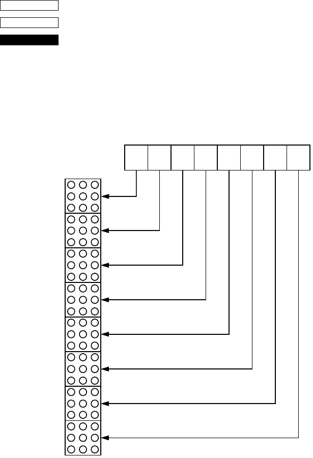
Dot Graphics Printing
<ESC> “K” n<0> m1 m2 ...
1B 4B n00 m1 m2 ...
Print normal density graphics
Receipt printer: Prints a 3 (horizontal) × 3 (vertical) dot bit image for
each dot of entered data. Data extending beyond the
right margin is ignored. The relationship between
the entered data and the actual printing is shown
below. The value of n is between 1 and 192.
CODE
HEX
FUNCTION
D8
MSB
DOT Position
Image data LSB
D7 D6 D5 D4 D3 D2 D1
1
1
2
3
4
22
21
23
24
5
6
7
8
9
10
11
12
13
14
15
16
17
18
19
20
23
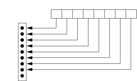
54
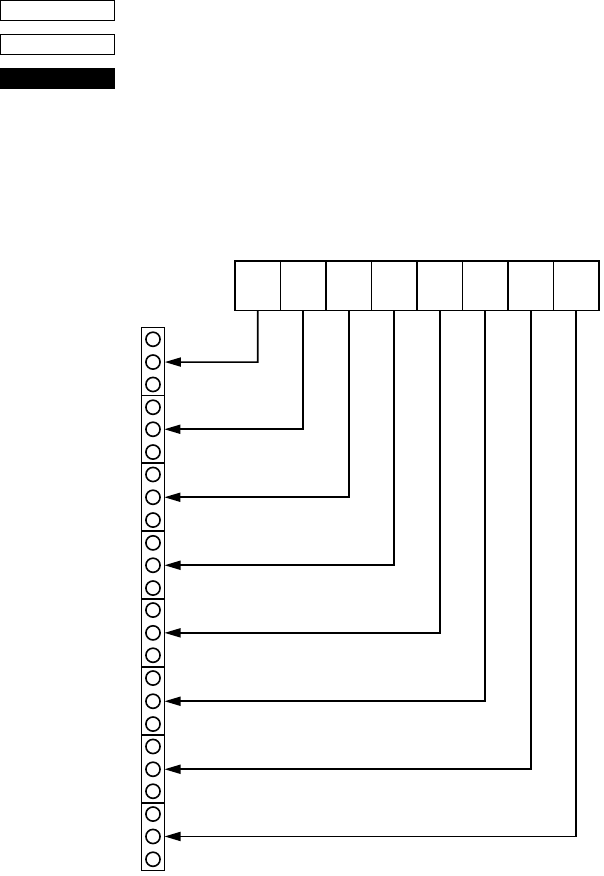
Slip printer: Prints a bit image of the number of dots specified by n. After printing the bit
image, the printer automatically returns to the character mode. The
relationship between the pins on the print head and the data is shown below.
The value of n is between 1 and 210.
A maximum of 210 data bytes can printed in one line. Any data exceeding
210 bytes is ignored. Only uni-directional printing is possible.
MSB LSB
Image data
D8D7D6D5D4D3D2D1
1
2
3
4
5
6
7
8
9
Dot Position
(Not Used)
55
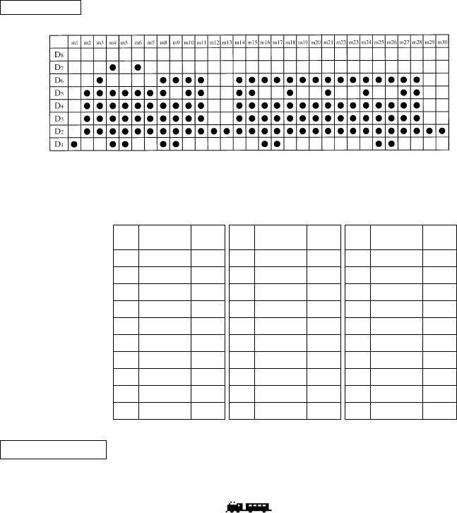
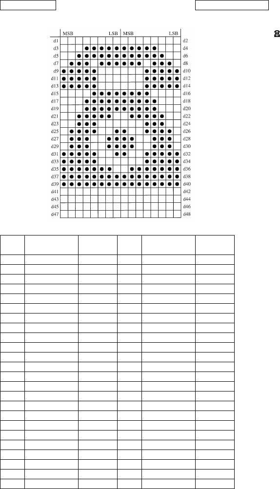
We will create the design below using a bit image.
First, since the volume of data is 30, n1 = (1E)H. If the data m1 ~ m30
is converted to hexadecimal, it appears as shown below.
Data Binary Hexa-
decimal Data Binary Hexa-
decimal Data Binary Hexa-
decimal
m1 00000001 01 m11 00111110 3E m21 00111110 3E
m2 00011110 1E m12 00000010 02 m22 00101110 2E
m3 00111110 3E m13 00000010 02 m23 00101110 2E
m4 01011111 5F m14 00111110 3E m24 00111110 3E
m5 00011111 1F m15 00111110 3E m25 00101111 2F
m6 01011110 5E m16 00101111 2F m26 00101111 2F
m7 00011110 1E m17 00101111 2F m27 00111110 3E
m8 00111111 3F m18 00111110 3E m28 00111110 3E
m9 00101111 2F m19 00101110 2E m29 00000010 02
m10 00111110 3E m20 00101110 2E m30 00000010 02
EXAMPLE
Printing Sample
56
<ESC> “L” n1 n2 m1 m2 ...
1B 4C n1 n2 m1 m2 ...
Print high density graphics
Receipt printer: Prints a 1 (horizontal) × 3 (vertical) dot bit image
for each dot of entered data. Data extending beyond
the right margin is ignored. The relationship
between the entered data and the actual printing is
shown below. The value of n1 + n2 × 256 is
between 1 and 576.
CODE
HEX
FUNCTION
D8
MSB
DOT Position
Image data LSB
D7 D6 D5 D4 D3 D2 D1
1
1
2
3
4
22
21
23
24
5
6
7
8
9
10
11
12
13
14
15
16
17
18
19
20
57
Slip printer: Prints a high density bit image of the number of dots specified by n1 and n2.
The value of n1 + 256 × n2 is between 1 and 420.
A maximum of 420 data bytes can printed in one line. Any data exceeding
420 bytes is ignored.
After printing the bit image, the printer automatically returns to the character
mode. The relationship between the pins on the print head and the data is the
same as those shown for the previous bit image code <ESC> “K”.
While printing a high density bit image, the horizontally adjacent dots
cannot be printed.
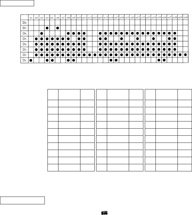
We will create the design below using a bit image.
First, since the volume of data is 30, n1 = (1E)H. If the data m1 ~ m30
is converted to hexadecimal, it appears as shown below.
Horizontal density is three times that of the bit image for <ESC>“k”.
(Compare the print samples.)
Data Binary Hexa-
decimal Data Binary Hexa-
decimal Data Binary Hexa-
decimal
m1 00000001 01 m11 00111110 3E m21 00111110 3E
m2 00011110 1E m12 00000010 02 m22 00101110 2E
m3 00111110 3E m13 00000010 02 m23 00101110 2E
m4 01011111 5F m14 00111110 3E m24 00111110 3E
m5 00011111 1F m15 00111110 3E m25 00101111 2F
m6 01011110 5E m16 00101111 2F m26 00101111 2F
m7 00011110 1E m17 00101111 2F m27 00111110 3E
m8 00111111 3F m18 00111110 3E m28 00111110 3E
m9 00101111 2F m19 00101110 2E m29 00000010 02
m10 00111110 3E m20 00101110 2E m30 00000010 02
EXAMPLE
Printing Sample

58
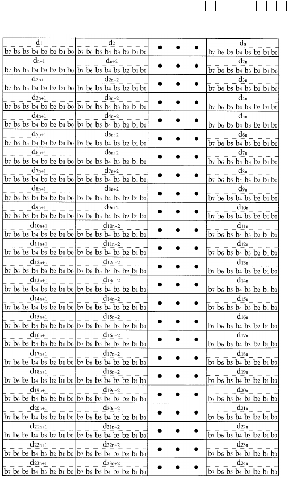
<ESC> “k” n<0> m1 m2 ...
1B 6B n00 m1 m2 ...
Print fine density graphics
Prints a 1 (horizontal) × 1 (vertical) dot bit image for each dot of
entered data. Data extending beyond the right margin is ignored. The
relationship between the entered data and the actual printing is
shown below. The value of n is between 1 and 72.
This command is only valid with the receipt printer.
CODE
HEX
FUNCTION
59
Relationship between image data and print dots
Image data
Dot position
b7 b6 b5 b4 b3 b2 b1 b0
60
Data Binary Hexa-
decimal Data Binary Hexa-
decimal
d1 00000000 00 d2 00000000 00
d3 00011111 1F d4 11111000 F8
d5 00111111 3F d6 11111100 FC
d7 01110111 77 d8 01110111 EE
d9 11111000 F8 d10 00011111 1F
d11 11111000 F8 d12 00011111 1F
d13 11111000 F8 d14 00011111 1F
d15 00001111 0F d16 11110000 F0
d17 00011111 1F d18 11111000 F8
d19 00011111 1F d20 11111000 F8
d21 00111110 3E d22 01111100 7C
d23 00111000 38 d24 00011100 1C
d25 01111001 79 d26 10011110 9E
d27 01110011 73 d28 11001110 CE
d29 01110011 73 d30 11001110 CE
d31 11111001 F9 d32 10011111 9F
d33 11111000 F8 d34 00011111 1F
d35 11111110 FE d36 01111111 7F
d37 11111111 FF d38 11111111 FF
d39 11111111 FF d40 11111111 FF
d41 00000000 00 d42 00000000 00
d43 00000000 00 d44 00000000 00
d45 00000000 00 d46 00000000 00
d47 00000000 00 d48 00000000 00
EXAMPLE Printin
g
Sample
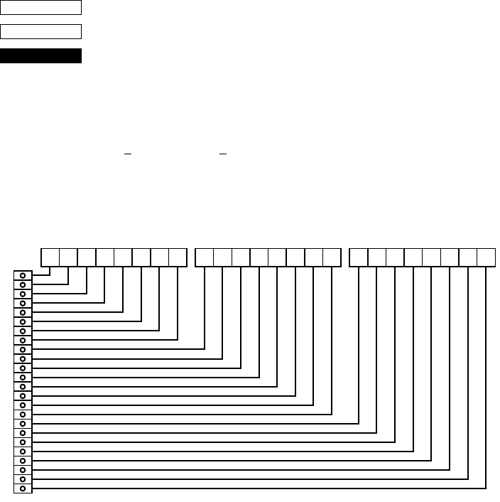
61
<ESC> “X” n1 n2 m1 m2 ...
1B 5 n1 n2 m1 m2 ...
Print fine density graphics
Prints a bit image of the input data using horizontal and vertical
resolutions of 8 dots/mm.
Data extending past the right margin is ignored.
The relationship between the input data and the actual printing is
shown below.
1n1 + n2 × 256 576
CODE
HEX
FUNCTION
≤ ≤
MSB
Dot
Position
LSB
b7 b6 b5 b4 b3 b2 b1 b0
d1••• MSB LSB
b7 b6 b5 b4 b3 b2 b1 b0
d2••• MSB LSB
b7 b6 b5 b4 b3 b2 b1 b0
d3•••
1
2
3
4
5
6
7
8
9
10
11
12
13
14
15
16
17
18
19
20
21
22
23
24
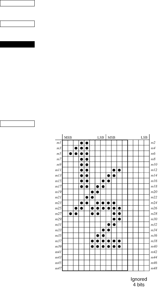
62
Download Graphics Printing
<ESC> “&” <1> <1> nm1m2... m48
<ESC> “&” “1” “1” nm1m2... m48
1B 26 01 01 nm1m2... m48
1B 26 31 31 nm1m2... m48
Define download character
Defines one new character and stores it in RAM for later use.
n is the character code of the character defined and must be between
21H and 7F4.
If the maximum of 32 external characters have already been stored,
the oldest stored external character are deleted so that new external
character can be stored.
The character matrix is 12 dots wide and 24 dots high.
Relationship between the character pattern and the character data is
shown below.
This command is only valid with the receipt printer.
CODE
HEX
FUNCTION
EXAMPLE
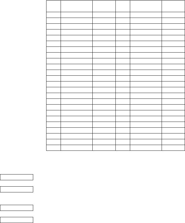
63
When the 7 × 9 (half dot) character size (default setting) is set:
<ESC> “&” <0> n1 n2 [m0 m1 m2 m3 m4 m5 m6 m7] n2 – n1 + 1
(1B)H (26)H (00)H n1 n2 [m0 m1 m2 m3 m4 m5 m6 m7] n2 – n1 + 1
When the 5 × 9 dot character size is set:
<ESC> “&” <0> n1 n2 [m0 m1 m2 m3 m4 m5] n2 – n1 + 1
(1B)H (26)H (00)H n1 n2 [m0 m1 m2 m3 m4 m5] n2 – n1 + 1
Data Binary Hexa-
decimal Data Binary Hexa-
decimal
m1 00011000 18 m2 00000000 00
m3 00111000 38 m4 00000000 00
m5 01111000 78 m6 00000000 00
m7 00011000 18 m8 00000000 00
m9 00011000 18 m10 00000000 00
m11 00011000 18 m12 01100000 60
m13 00011000 18 m14 11000000 C0
m15 00011001 19 m16 10000000 80
m17 00011011 1B m18 00000000 00
m19 00000110 06 m20 00000000 00
m21 00001100 0C m22 00000000 00
m23 00011011 1B m24 11000000 C0
m25 00110111 37 m26 11100000 E0
m27 01100110 66 m28 01100000 60
m29 00000000 00 m30 01100000 60
m31 00000000 00 m32 11000000 C0
m33 00000001 01 m34 10000000 80
m35 00000011 03 m36 00000000 00
m37 00000111 07 m38 11100000 E0
m39 00000111 07 m40 11100000 E0
m41 00000000 00 m42 00000000 00
m43 00000000 00 m44 00000000 00
m45 00000000 00 m46 00000000 00
m47 00000000 00 m48 00000000 00
CODE
HEX
CODE
HEX
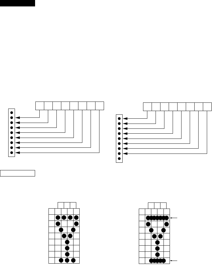
64
Define download character (7 × 9 (half dot) font or 5 × 9 dot font)
Defines download characters
Up to 10 download characters can be defined and the defined
character patterns can be stored in the printer’s RAM.
The values of n1 and n2 are between (21)H and (7F)H with n1 less
than or equal to n2 and the value of m0 is either (00)H or (80)H.
Defining of download characters begins with character code n1 and
completes with n2. When only one character is defined, n1 = n2.
m0 indicates the relationship between the character pattern and print
head.
m1 m2.... Indicate the character pattern
This command is only valid with the slip printer.
When the 7 × 9 (half dot) character size (default setting) is set, the
horizontally adjacent dots cannot be printed.
FUNCTION
MSB
When m0=(00)H LSB
D8D7D6D5D4D3D2 D1
1
2
3
4
5
6
7
8
9
Pin No.
(Not used)
MSB
When m0=(80)H LSB
D8D7D6D5D4D3D2 D1
1
2
3
4
5
6
7
8
9
Pin No.
(Not used)
EXAMPLE
m2 m4 m6
m1
D8
D7
D6
D5
D4
D3
D2
D1
m3 m5 m7
Printing possible Printing not possible
m2 m4 m6
m1
D8
D7
D6
D5
D4
D3
D2
D1
m3 m5 m7 Over lapping
horizontally
Over lapping
horizontally
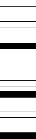
65
<ESC> “&” <1> <0> n
<ESC> “&” “1” “0” n
1B 26 01 00 n
1B 26 31 30 n
Delete a download character (12 × 24 dot font)
Deletes the download character which was assigned the value n.
This command is only valid with the receipt printer.
<ESC> “%” “1” or <ESC> “%” <1>
1B 25 31 or 1B 25 01
Enable download character set
Enables the download character set.
<ESC> “%” “0” or <ESC> “%” <0>
1B 25 30 or 1B 25 00
Disable download character set
Disables the selected download character set and returns to the built-
in ROM character set.
CODE
HEX
FUNCTION
CODE
HEX
FUNCTION
CODE
HEX
FUNCTION

66
Peripheral Device Control
<ESC> <BEL> n1 n2
1B 07 n1 n2
Define drive pulse width for peripheral device #1
Defines the drive pulse width for peripheral devices requiring other
than standard 200 ms pulse time and delay time.
n1 indicates the energizing time and n2 indicates the delay time,
using 10ms units.
<BEL>
07
Control peripheral device #1
Executes drive pulse for peripheral device #1.
<FS>
1C
Control peripheral device #1 immediately
Executes drive pulse for peripheral device #1 immediately.
<EM>
19
Control peripheral device #2 immediately
Drives peripheral device #2. The drive pulse width and delay time
are fixed at 200 ms.
<SUB>
1A
Control peripheral device #2 immediately
Drives peripheral device #2. The drive pulse width and delay time
are fixed at 200 ms.
CODE
HEX
FUNCTION
CODE
HEX
FUNCTION
CODE
HEX
FUNCTION
CODE
HEX
FUNCTION
CODE
HEX
FUNCTION

67
Auto Cutter Control
<ESC> “d” “0” or <ESC> “d” <0>
1B 64 30 or 1B 64 00
Full-cut command to the auto cutter
Cuts the receipt paper fully.
This command is only valid with the receipt printer.
<ESC> “d” “1” or <ESC> “d” <1>
1B 64 31 or 1B 64 01
Partial-cut command to the auto cutter
Cuts the receipt paper partially.
This command is only valid with the receipt printer.
CODE
HEX
FUNCTION
CODE
HEX
FUNCTION

68
Slip Printer Control
<ESC> <SI> n
1B 0F n
Setting slip sensor
Sets the slip printer TOF/BOF sensor according to the value of n.
TOF Sensor BOF Sensor
n = 00, “0” : Valid Valid
01, “1” : Valid Invalid
02, “2” : Invalid Valid
03, “3” : Invalid Invalid
Default values are:
n = 0 when memory switch 5-2 = 0 (factory setting)
n = 3 when memory switch 5-2 = 1
<ESC> <FF> n
1B 0C n
Slip function
After printing the data in the line buffer, operates the slip printer
according to the value of n.
n = 00, “0” : Operates the clamp
01, “1” : Releases the paper
02, “2” : Releases the paper and waits until it is removed
03, “3” : Feeds the paper backward (backfeed) until it
moves past the TOF sensor, then releases the
paper. (See NOTE below.)
04, “4” : Feeds the paper into the printer (operational feed)
until it moves past the BOF sensor, then releases
the paper.
05, “5” : Feeds the paper according to the direction and
length set by <ESC> <VT> m n (the paper is not
released)
(NOTE) When the slip paper is attached to duplicates, a paper jam
may occur if the paper is always fed backward. Therefore,
the paper should not be ejected with n=3. To feed slip paper
attached to duplicates backward, use <ESC> <VT> to set
the eject length to about half of the paper length, then eject
the paper using <ESC> <FF> 5.
This command is only valid with the slip printer.
CODE
HEX
FUNCTION
CODE
HEX
FUNCTION
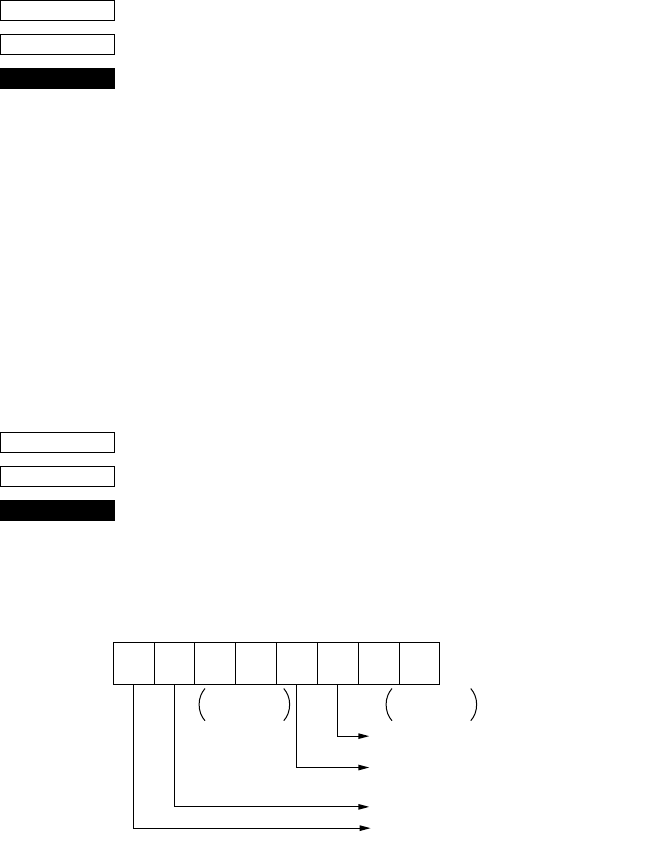
69
<ESC> <VT> mn
1B 0B mn
Set the paper eject direction/length
Sets the length of the ejection operation performed using <ESC>
<FF> 5 in line mode.
The value of m determines the ejection direction.
When m= “+”: the ejection direction is into the printer (operational
feed), and the ejection length is n lines (at the current
carriage return)
When m= “-”: the ejection direction is backward (backfeed), and
the ejection length is n lines (at the current carriage
return)
When m= 0 : the ejection direction is backward (backfeed), and
the ejection length is n inches
The default value of n is 0.
This command is only valid with the slip printer.
<EOT>
04
Slip status enquiry
Sends slip printer status information to the host computer.
Status b1 and b5 is variable.
This command is only valid with the slip printer.
CODE
HEX
FUNCTION
CODE
HEX
FUNCTION
Status b7 b6 b5 b4 b3 b2 b1 b0
10
TOF sensor 1: No paper
BOF sensor 1: No paper
Slip printer mechanical error 1: Error
Slip release/clamp 1: Clamp
0: Release
Constantly
set at “1” Constantly
set at “0”

70
<ESC> <EM> nm<LF> <NUL>
1B 19 nm0A 00
Set the wait time until the automatic clamp is activated
Set the wait time between paper insertion (TOF/BOF sensor senses
the paper) and automatic clamp activation by n × 0.1 sec.
The default value of n is 7 (wait time is 0.7 sec.)
The value of m is fixed to 0.
This command is only valid with the slip printer, besides memory
switch 5-1 is set to 0.
Page Mode
<ESC> “n”
1B 6E
Select page mode
Switches from line mode (default) to page mode.
This code is only valid when it is entered at the beginning of the line.
The page mode is suitable even though data is printed in the
rotational direction specified by <ESC> “T” n and in the page
coordinate range specified by <ESC> “*” •••, and though paper with
a horizontal length of a check, etc. is rotated 90 or 270 and printing
is carried out in all modes.
In page mode, since OR is applied to the data in the print area,
characters and bit images can be printed overlapping each other and
each character can be rotated and oriented independently.
In page mode, if printing data and a command such as <CR> or
<LF> are sent in the same way as in line mode, there is an automatic
rotation to the printer side.
All printing of data in the print area is performed according to <LF>.
After printing according to <FF>, the printer returns to line mode. In
addition, if <ESC> “!”, <ESC> “@” or <CAN> are specified,
printing is not performed and the printer leaves page mode and
returns to line mode.
While returning to line mode, the data in the printer buffer, the area
coordinates and the rotation directions are all cleared.
This command is only valid with the slip printer.
The following restrictions exist in page mode.
1) In page mode, half-dot characters cannot be printed since
printing is carried out in normal dot units.
When entering page mode, the ANK font is automatically set to
a 5 × 9 (2 pulses = 1 dot) font.
Since the 7 × 9 font and 5 × 9 (3 pulses = 1 dot) font commands
cannot be executed in page mode, they are executed after the
CODE
HEX
FUNCTION
CODE
HEX
FUNCTION
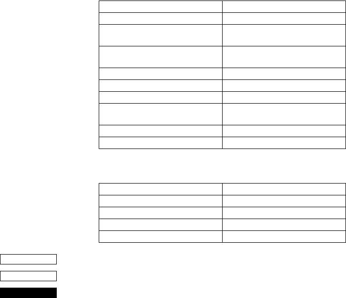
71
printer returns to line mode.
High density printing of graphics is ignored.
2) Paper feed command
In paper mode, the paper feed command and carriage return are
executed in units of dots. A 1/72-inch (0.353-mm) paper feed is
considered 1 dot. Since a 1-dot pitch in the horizontal direction
is 0.30 mm and a 1-dot pitch in the vertical direction is 0.353
mm, the paper amount that is fed while printing using a 90 or
270 rotation is less when compared with a 0 or 150 rotation.
As a result, when printing using a 90 or 270 rotation, execute a
test print, check the horizontal and vertical dot alignment, then
adjust the alignment as necessary.
3) The following commands are not executed in page mode, but
are stored and executed when the printer returns to line mode.
4) The following commands are ignored in page mode.
<ESC> “!”
1B 21
Select line mode (default)
If this command is specified while in page mode, printing is not
carried out and the printer returns to line mode.
This command is only valid with the slip printer.
Select 7 × 9 (half dot) font <ESC> “M”
Select 5 × 9 (3 pulses = 1 dot) font <ESC> “:”
Inverted printing/Cancel inverted
printing
<SI>/<DC2>
Select highlight printing/Cancel
highlight printing
<ESC> “4”/<ESC> “5”
Underlining <ESC> “-” n
Upperlining <ESC> “_” n
Select print direction <ESC> “U” n
Select emphasized printing/Cancel
emphasized printing
<ESC> “E”/<ESC> “F”
Select left margin <ESC> “1” n
Select right margn <ESC> “Q” n
One time backfeed <ESC> “j” n
Print high density graphics <ESC> “L” •••
Slip function <ESC> <FF> n
Select print station <ESC> “+” “A” n
STX-ETX mode <STX> ••• <ETX>
CODE
HEX
FUNCTION
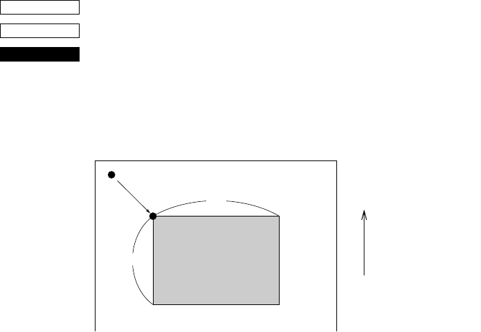
72
<ESC> “*” XL XHYLYHdXLdXHdYLdYH
1B 2A XLXHYLYHdXLdXHdYLdYH
Setting print area in page mode
The coordinates of the current position at the moment that page
mode is entered are (0,0). The starting point of the print area is
defined by XL, XH, YL and YH. In addition, the length DX in the X
direction is specified by dXL and dXH, and the length DY in the Y
direction is specified by dYL and dYH.
Starting point X0 = XL + (XH × 256) dots
Starting point Y0 = YL + (YH × 256) dots
Length in horizontal direction DX = dXL + (dXH × 256) dots
Length in vertical direction DY = dYL + (dYH × 256) dots
The values of XL, YL, dXL and dYL are between 0 and 255, and the
values of XH, YH, dXH and dYH are between 0 and 1.
However, dXL = dXH = 0 and dYL = dYH = 0 are not included.
In addition, since the maximum range in the X direction (XO + DX)
is 210 dots and the maximum range in the Y direction (YO + DY) is
720 dots, each parameter should be specified to satisfy these ranges.
When the power is turned on, XL = XH = YL = YH = 0 (XO,YO =
0,0)dXL = 210, dXH = 0 (DX = 210) and
dYL = 64, dYH = 2 (DY = 576).
This command is stored, even in line mode, and the position at the
time that page mode is entered is used as the standard point (0,0).
Since the bottom of the character is used as the baseline, a minimum
print area of 8 dots are necessary in the character height direction to
print data in the page. (When printing a magnified character height,
the paper must be fed before printing.)
This command is only valid with the slip printer.
CODE
HEX
FUNCTION
Paper feed direction
Current position (0,0)
Print areaDY
DX
(X0,Y0)
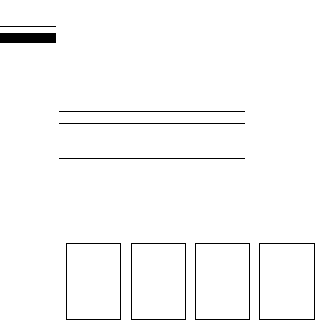
73
When n = 4, “4,” special mode page mode functions as check high-speed printing mode.
<ESC> “T” n
1B 54 n
Setting print direction in page mode
Sets the direction in which the printing will be executed in page
mode according to the value of n.
This command is only valid in line mode.
The default value of n is 0.
<Rotation direction examples>
n = 0 n = 1 or 4 n = 2 n = 3
0° rotation 270° rotation 180° rotation 90° rotation
<N=4,“4”: Check high-speed printing mode>
This parameter is only valid when no character data is expanded
into the page area, and this command is added immediately after
<ESC>“n”.
Also, once the check high-speed printing mode has been entered
with <ESC>“T”4, it is not possible to move across to a different
rotation mode (<ESC>“T”0-3) until the page mode has been exited.
The check high-speed printing mode provides high-speed printing
with the check at a 270 degree rotation angle and bi-directional
printing, and a wide range of limitations have been included to
enable bi-directional printing.
Value of n Mode
0 or “0” 0 rotation mode (uni-directional printing)
1 or “1” 270 rotation mode (uni-directional printing)
2 or “2” 180 rotation mode (uni-directional printing)
3 or “3” 90 rotation mode (uni-directional printing)
4 or “4” 270 rotation mode (bi-directional printing)
CODE
HEX
FUNCTION
12345•••
ABCDE•••
12345•••
ABCDE•••
12345•••
ABCDE•••
12345•••
ABCDE•••

74
This mode can only be used with printing data that uses a 5 X 9 (2P-
1) font without decorations.
The limitations are listed below. The quality of the printed product
cannot be guaranteed if these limitations are removed and the unit
used.
[Limitations on the check high-speed printing mode]
• The only characters that can be printed are the 5 X 9 (2P-1) font
ANK characters.
• The double-sized width command cannot be used (the double-
sized height command may be used.)
• The bit image command cannot be used.
• Horizontal tabs cannot be used.
• The space setting command for the space between characters
cannot be used.
• The following limitations apply for the Y direction in the printing
area (value set with <ESC> “*”...)
1As To=0 has been fixed as the starting point for the printing
area, the printing area command set with <ESC> “*” ....
Must be specified with Yo=YL=YH=0. (It will forcibly set
at 0 if it is at any other setting.)
2The value of Dy must be a six-fold value.
As bi-directional printing in 6-pin units will be performed in this
mode, there are cases where the characters that have been
entered in a misaligned state will be printed in a wave-like style
and will not be able to be distinguished when the value of Dy is
anything other than a six-fold value as a joint will be
established within a single character for return printing.
Consequently, setting anything other than the six-fold value
must not be carried out. However, the printer will discard any
remainders from dividing by six and automatically correct it
into six-fold when any value other than six -fold has been set.
This command is only valid with the slip printer.
<FF>
0C
Print in page mode (only valid when in page mode)
This command can only activate the slip printer. In page mode, all
page data in the page area is printed, then the printer returns to line
mode. After all the page data is printed, the data in the page, the page
print area and the print direction are all initialized.
In addition, this command has no function in line mode.
CODE
HEX
FUNCTION
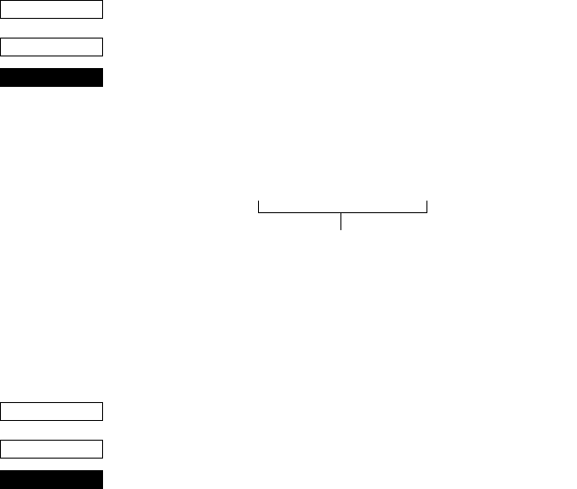
75
Customer display commands (Combo mode only)
<ESC> “S”
1B 53
Start customer display
Subsequent data is sent through the customer display. Customer
display data is sent as follows.
This command is saved in the print buffer and retrieved from the
print buffer and executed in the same way as the other print data.
This command is only effective in the combination mode and when
memory switch 0-8 = 0.
When the customer display is being used, the option RS232C I/F
communication conditions must be baud rate = 9699BPS, data
length = 8 bits, no parity, so set the dip switches accordingly.
<ESC> “G”
1B 47
End customer display
This command is regarded as the customer display data end code and
subsequent data is processed as print data. This command is saved in
the print buffer and retrieved from the print buffer and executed in
the same way as the other print data. This command is only effective
in the combination mode and when memory switch 0-8 = 0.
This command is only valid with the slip printer.
CODE
HEX
FUNCTION
<ESC> “S” Customer display data <ESC> “G”
Through the customer display
CODE
HEX
FUNCTION

76
Other Commands
<CAN>
18
Cancel printer buffer & Initialize printer
Clears the line buffer, and initializes the commands set already.
Does not affect the external equipment drive conditions set by the
code <ESC> <BEL> n1 n2. (This is the same during a mechanical
error.)
(Line buffer means the print data expansion area.)
If <CAN> is specified in page mode while printing using the slip
printer, printing is not carried out and the printer returns to line mode
from page mode.
In addition, <CAN> initializes the print station selection. If the slip
printer was selected, the receipt printer will be re-selected.
This command cannot recover from errors or return to the on-line
status from off-line.
<DC3>
13
Deselect printer
Deselects the printer. The printer disregards all subsequent
characters and commands except <DC1>, which activates the
printer.
<DC1>
11
Set select mode
When the printer receives a <DC1> code, the deselect mode is
canceled and data following this code is input to the buffer.
<RS>
1E
Beep the buzzer
Sounds a brief beep tone.
CODE
HEX
FUNCTION
CODE
HEX
FUNCTION
CODE
HEX
FUNCTION
CODE
HEX
FUNCTION
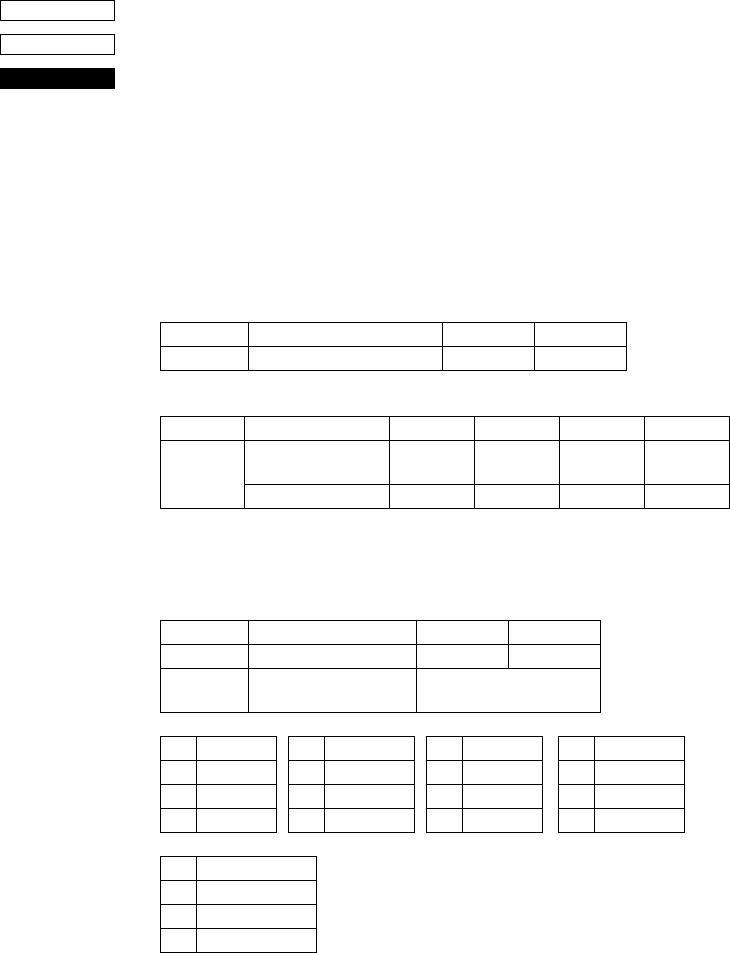
77
<ESC> “# N , n1n2n3n4” <LF> <NUL>
1B 23 N 2C n1n2n3n4 0A 00
Set the memory switch. In order to enable changed memory switch
setting, turn the printer OFF and ON again or send printer reset
command (<ESC> “?”<LF><NUL>”) to the printer. Changed
memory switch settings are stored in EEPROM and these setting will
be stored as long as the time when they are changed again.
N :Memory switch number (“0”, “1”, “2”, “3”, “4”, “5”)
n1n2n3n4 :Mode settings (For details see below)
1) N=0 (Star mode only)
n1 :Always “0”
n3 :Always “0” (Default)
(Default)
2) N=1 (Star mode only)
n1 :Always “0”
n2 :Always “0” (Default)
Parameter Setting “0” “1”
n2 Customer display commands Valid Invalid
Parameter Setting “0” to “3” “4” to “7” “8” to “A” “B” to “F”
n4
Receipt FF command Form Feed Paper Feed,
Cut & Back
Form Feed Paper Feed,
Cut & Back
FF cut mode — Full-cut — Partial-cut
Parameter Setting “0” “1”
n3 Zero style Normal zero Slashed zero
n4 International character
set See below
n4 Country n4 Country n4 Country n4 Country
“0” USA “3” UK “6” Italy “9” Norway
“1” France “4” Denmark #1 “7” Spain #1 “A” Denmark #2
“2” Germany “5” Sweden “8” Japan “B” Spain #2
n4 Country
“C” Latin America
CODE
HEX
FUNCTION
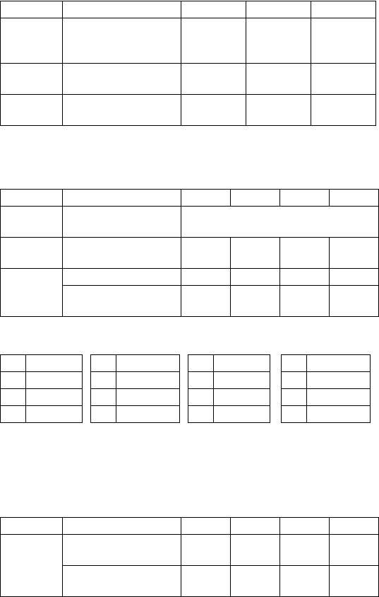
78
3) N=2 n3 :Always “0” (Default)
4) N=3 (Star mode only)
n1 :Always “0” (Default)
5) N=4 (Star mode)
n2 :Always “0”
n3 :Always “0”
n4 :Always “0” (Default)
Parameter Setting “0” “1” Remark
n1 Receipt printer ESC d
command
Receipt printer
Cut Paper feed,
& Cut
Star mode
only
n2 Receipt printer cutter Valid Invalid Star and
ESC/POS
n4 Receipt printer paper
near end
Invalid Valid Star mode
only
Parameter Setting “0” “1” “2” “3”
n2 Character table (Code
page) See belows
n3 Receipt printer printer
column
48 38 – –
n4 CR code Invalid Invalid Valid Valid
Receipt printer line feed
(mm)
4343
n2 Code page n2 Code page n2 Code page n2 Code page
“0” Normal “3” 437 “6” 860 “9” 865
“1” katakana “4” 850 “7” 861 “A” 866
“2” 437 “5” 852 “8” 863
Parameter Setting “0” “1” “2” “3”
n1 X on/X off Timing When
Toggled
every 3
sec
When
Toggled
every 3
sec
RTS Signal Condition Save as
DTR
Save as
DTR
always
SPACE
always
SPACE
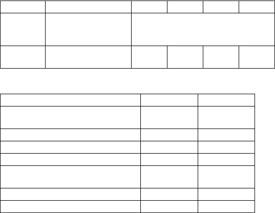
79
N=4 (ESC/POS mode)
n1 :Always “0”
n2 :Always “0” (Default)
Parameter :n3
Parameter Setting “0”’ “1” “2” “3”
n3 DTR signal during
setting status
transmission
See belows
n4 Data receipt error “?”
printed
Ignored “?”
printed
Ignored
Setting (DTR signal) “0”, “1” “2”, “3”
1. From when the power is turned on or
I/F reset until communication possible BUSY BUSY
2. Test printing BUSY BUSY
3. Paper feed by paper feed switch — BUSY
4. Stop due to no paper — BUSY
5. During waiting for switch input in
macro execution — BUSY
6. Other error — BUSY
7. Receiving buffer full BUSY BUSY
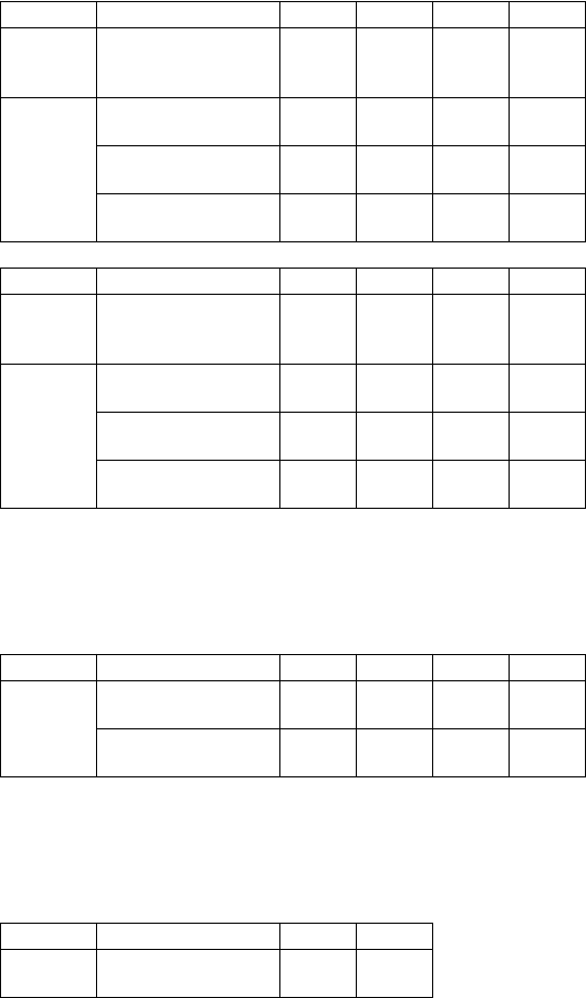
80
6) N=5 (Star mode)
n1 :Always “0”
n3 :Always “0” (Default)
N=5 (ESC/POS mode)
n1 :Always “0”
n2 :Always “0”
n3 :Always “0” (Default)
N=An1 :Always “0”
n2 :Always “0”
n3 :Always “0” (Default)
Parameter Setting “0” “1” “2” “3”
n2 When slip printer <CR>
code is valid
Print +
line feed
(CRLF)
print
(CR)
Print +
line feed
(CRLF)
print
(CR)
n4 Initial status of the TOF/
BOF sensor
Valid Valid Valid Valid
Slip printer automatic
clamp
Valid Valid Invalid Invalid
Slip printer automatic
starting print positioning
Valid Invalid Valid Invalid
Parameter Setting “4” “5” “6” “7”
n2 When slip printer <CR>
code is valid
Print +
line feed
(CRLF)
print
(CR)
Print +
line feed
(CRLF)
print
(CR)
n4 Initial status of the TOF/
BOF sensor
Invalid Invalid Invalid Invalid
Slip printer automatic
clamp
Valid Valid Invalid Invalid
Slip printer automatic
starting print positioning
Valid Invalid Valid Invalid
Parameter Setting “0” “1” “2” “3”
n4 Slip printer automatic
clamp
Valid Valid Invalid Invalid
Slip printer automatic
starting print positioning
Valid Invalid Valid Invalid
Parameter Setting “0” “1”
n4 Receipt adherence-
prevention control
Valid Invalid
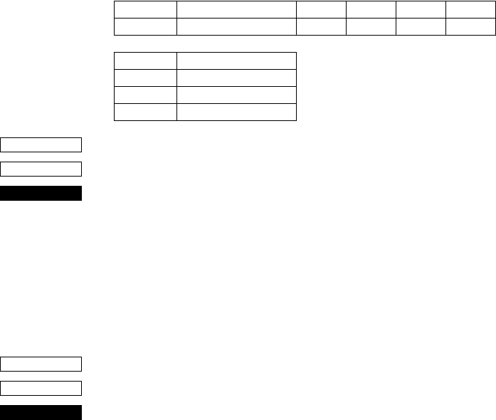
81
N=Dn1 :Always “0”
n2 :Always “0”
n3 :Always “0”
<ESC> “@”
1B 40
Initialize printer
Reinitializes the printer. Clears the print buffer and returns settings
to their power-up values.
Does not clear the input buffer, downloaded characters, or conditions
for peripheral devices.
If this command is specified in page mode while printing using the
slip printer, printing is not carried out and the printer returns to line
mode from page mode.
This command cannot recover from errors or return to the on-line
status from off-line.
<ENQ>
05
Enquiry
Causes the printer to transmit a status byte.
Parameter Setting “0” “1” “2” “3”
n2 Thermal head rank A B C C
Rank Average resistance value
A 1215 ± 67 Ω
B 1350 ± 67 Ω
C 1485 ± 67 Ω
CODE
HEX
FUNCTION
CODE
HEX
FUNCTION
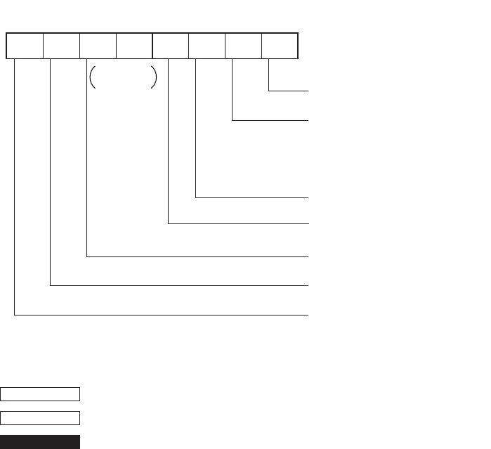
82
Status byte
<ESC> “?” <LF> <NUL>
1B 3F 0A 00
Reset the printer hardware.
Resets the printer hardware and produces a test print
0
Receipt printer head-up error
Receipt printer auto cutter error
Receipt printer thermistor error
Cover open error
Slip printer mechanical error
1: Error
Vertical parity error
1: Error
Framing error
1: Error
Buffer empty
1: Empty
Buffer overflow
1: Overflow
Compulsion switch
1: High level (Switch is set to ON.)
b7 b6 b5 b4 b3 b2 b1 b0
Constantly
set at 0
Status
Receipt paper empty
1: Empty
Status b3 is variable.
CODE
HEX
FUNCTION

83
Chapter 10: ESC/POS Mode
TM-T85 mode
Code Function
HT Horizontal tab
LF Print line feed
FF Page mode print and return
DLE EOT Real time transmission of status
DLE ENQ Real time request to printer
CAN Cancel print data in page mode
ESC FF Print page mode data
ESC SP Set right space amount of character
ESC ! Universal print mode designation
ESC $ Designate absolute printing
ESC % Designate/cancel download characters set
ESC & Define download characters
ESC * Designate bit image mode
ESC - Designate/cancel underline
ESC 2 Set 1/6 inch line feed amount
ESC 3 Set line feed amount
ESC = Select peripheral equipment
ESC ? Delete download characters
ESC @ Initialize printer
ESC D Set horizontal tab position
ESC E Designate/cancel emphasized print
ESC G Designate/cancel double print
ESC J Print and paper feed
ESC L Select page mode
ESC R Select international characters
ESC S Select standard mode
ESC T Select character print direction in print mode
ESC V Designate/cancel 90° character rotation
ESC W Set print range in page mode
ESC \ Designate relative position
ESC a Align position
ESC c4 Select no effective paper detector at print stop
ESC c5 Enable/disable panel switch

84
ESC d Print and paper feed “n” lines
ESC i Partial cut (one section remaining)
ESC p Designate pulse generation
ESC t Select character code table
ESC u Transmission of peripheral equipment status
ESC v Transmission of paper detection status
ESC { Designate/cancel inverted printing
GS ! Designate character size
GS $ Designate absolute position of vertical direction of characters in page mode
GS * Define download bit image
GS / Print download bit image
GS : Start/finish macro definition
GS B Designate/cancel reverse printing
GS H Select print position of HRI characters
GS I Printer ID transmission
GS L Set left margin
GS P Set basic calculated pitch
GS V Paper cut
GS W Set print range
GS \ Designate the relative position of vertical characters when printing in the page
mode
GS ^ Execute macro
GS a Enable/disable automatic status transmission
GS b Designate/cancel smoothing
GS f Select HRI character font
GS h Set bar code height
GS k Printing of bar code
GS r Transmission of status
GS w Set lateral size of bar code
Code Function

85
TM-295 mode
Code Function
HT Horizontal tab
LF Print line feed
FF Page mode print and return
DLE EOT Real time transmission of status
CAN Cancel print data in page mode
ESC SP Set right space amount of character
ESC ! Universal print mode designation
ESC % Designate/cancel download characters set
ESC & Define download characters
ESC * Designate bit image mode
ESC 2 Set 1/6 inch line feed amount
ESC 3 Set line feed amount
ESC = Select peripheral equipment
ESC @ Initialize printer
ESC C Single sheet paper eject length setting
ESC D Set horizontal tab position
ESC F Designation/cancel single sheet paper reverse direction ejection
ESC J Print and feed
ESC K Print and reverse direction feed
ESC L Select page mode
ESC R Select international characters
ESC T Select character print direction in print mode
ESC W Set print range in page mode
ESC c4 Select no effective paper detector at print stop
ESC c5 Enable/disable panel switch
ESC d Print and paper feed “n” lines
ESC e Print and reverse direction feed “n” lines
ESC f Single sheet paper hold time setting
ESC p Designate pulse generation
ESC q Release
ESC t Select character code table
ESC u Transmission of peripheral equipment status
ESC v Transmission of paper detection status
ESC { Designate/cancel inverted printing
GS I Printer ID transmission
GS a Enable/disable automatic status transmission
GS r Transmission of status

86
TM-295 mode emulation cautionary items
Since, as shown below, the paper feed pitch, dot pitch and the installation
distances between the TOF/BOF sensors and the print head differ depending on
the mechanism of the SCP700 slip and TM-295, the printing results may not be
the same because of the differences in the mechanism. Also, even though, since
the TM-295 is a shuttle printer, the paper feed set values and actual paper feed
amount are different.
<Influence and command differences due to differences in paper feed motor
pitch and horizontal/vertical dot pitch>
Since the pitches are different, the printing results are reduced in the vertical/
horizontal direction compared to the TM-295. Especially in the page mode,
since the coordinates are controlled in dots, the printing results are reduced.
(There is a difference of n/60” dots - n/72” dots in the Y direction.)
In the case of the line mode, since the difference in the paper feed pitch is
absorbed as much as possible, the commands which are connected with the n/
60 inch unit paper feed (<ESC> “3” n, <ESC> “J” n, <ESC> “K” n) use
INT((6n/5)+0.5).
However, since even in this case, depending on the value of n, the paper feed
amount may not be exactly the same, the vertical direction printing position may
be different.
Difference SCP700 slip TM-295
Difference in the paper feed motor
pitch 1/144 inch units 1/60 inch units
Difference in the vertical direction
dot pitch 0.353mm 0.423mm
Difference in the horizontal
direction dot pitch 0.30mm 0.315mm
Difference in the distance from the
top of the paper to the top of the
print head
26.5mm
(When automatically feeding)
26.5mm ~ 36.5mm
Variable with mechanical
stopper
Difference in the distance from the
TOF sensor to the top of the print
head
26.0mm
3.0mm ~ 13.0mm
Variable with mechanical
stopper
Difference in the distance from the
BOF sensor to the bottom of the
print head
38.1mm 27.3mm
87
<Influence due to the difference in the TOF and BOF sensor positions>
The paper position when the condition of the TOF or BOF sensor changes due
to the status is different to that of the TM-295.
Since the position of the BOF sensor is especially different, whereas the BOF
sensor reports “no paper” at 27.3mm from the bottom of the paper with the TM-
295, the BOF sensor reports “no paper” at approximately 38mm from the
bottom of the paper with the SCP700. Therefore, when the BOF “no paper”
sensor is effective, the BOF sensor “no paper” is reported quicker than with the
TM-295 and it may not be possible to print in the same position at the bottom
of the same form.
For this reason, by controlling the printing so that it does not stop until
approximately 27.3mm from the bottom of the paper even if the paper has
passed the BOF sensor at the 38.1mm position, this difference is compensated.
However, due to the differences in the paper feed pitch (star = n/72”, TM-295 =
n/60”), the emulation is not perfect.
<Influence due to mechanical stopper position>
With the TM-295, by adjusting the mechanical stopper position, the paper top
position can be changed between 0 to 10mm. However, since the mechanical
stopper position is fixed with the SCP700, if the TM-295 mechanical stopper
position is changed and the printing results are compared, they may be different.
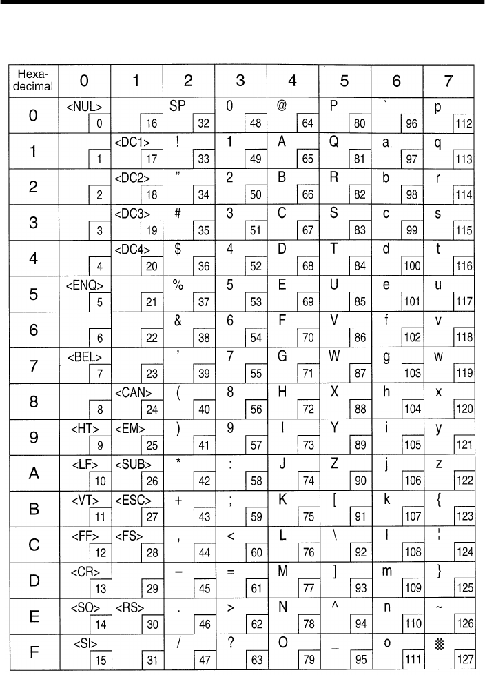
88
Appendix : Character Code Tables
Star Mode
(Character table: Normal)
Note: The (7F)H code is a space when neither normal nor katakana.
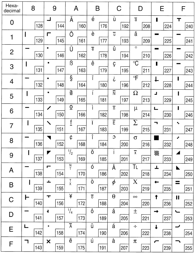
89
Star Mode
(Character table: Normal)
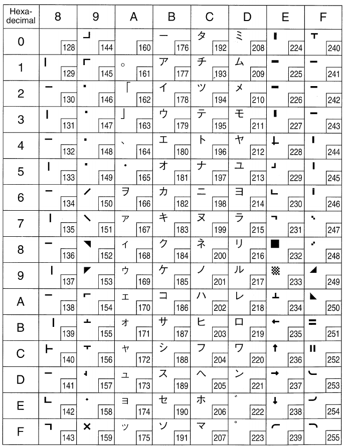
90
Star Mode
(Character table: katakana)
Note: Other characters are the same as those for Character table: Normal.
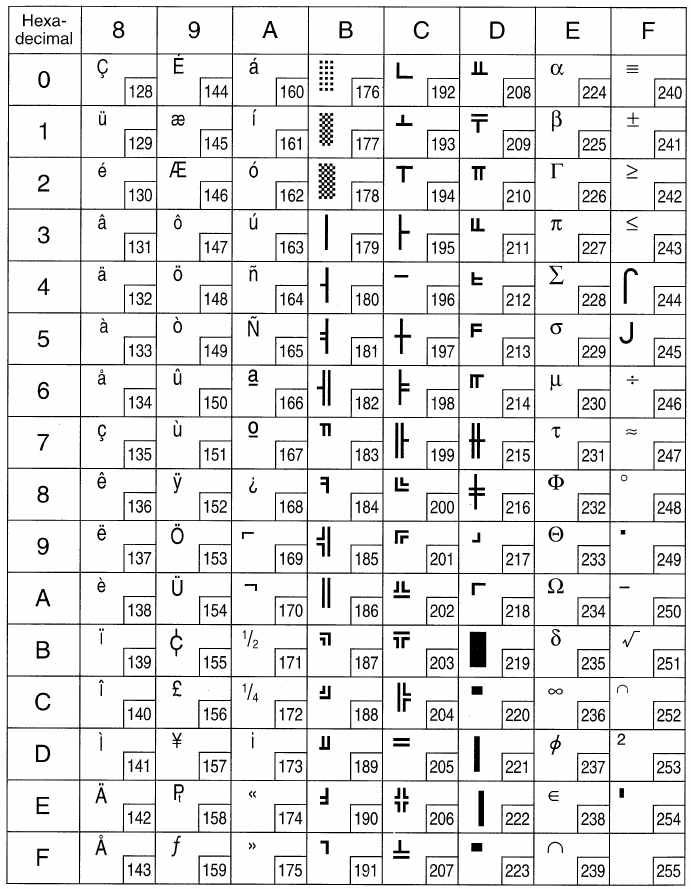
91
Star Mode
(Character table: IBM (Code page 437))
Note: Other characters are the same as those for Character table: Normal.
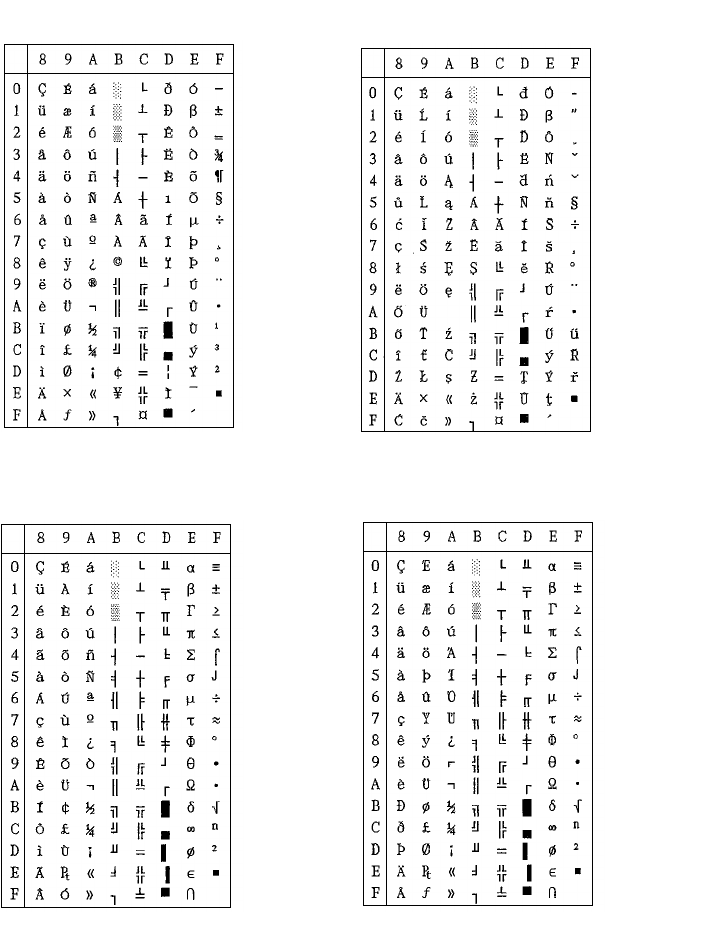
92
Star Mode
Note: Other characters are the same as those for Character table: Normal
Code Page #850
Multi-lingual Code Page #852
Latin-2
Code Page #860
Portuguese Code Page #861
Icelandic
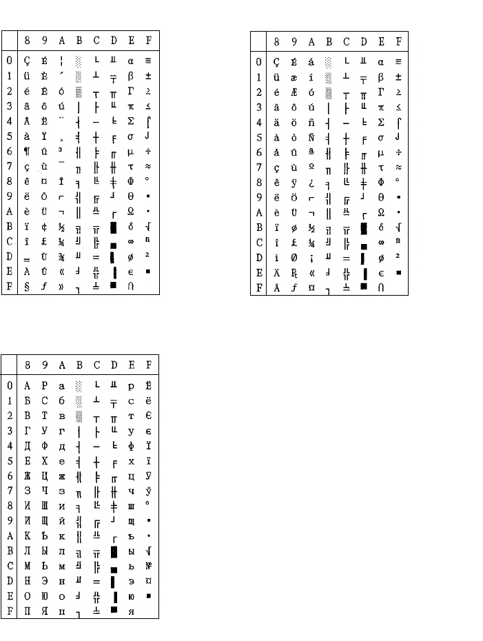
93
Note: Other characters are the same as those for Character table: Normal
Code Page #863
Canadian French Code Page #865
Nordic
Code Page #866
Russian
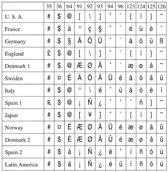
94
Star Mode
International Character Set
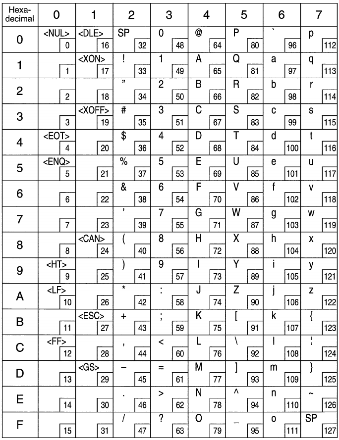
95
ESC/POS Mode
Page 0 (PC437)
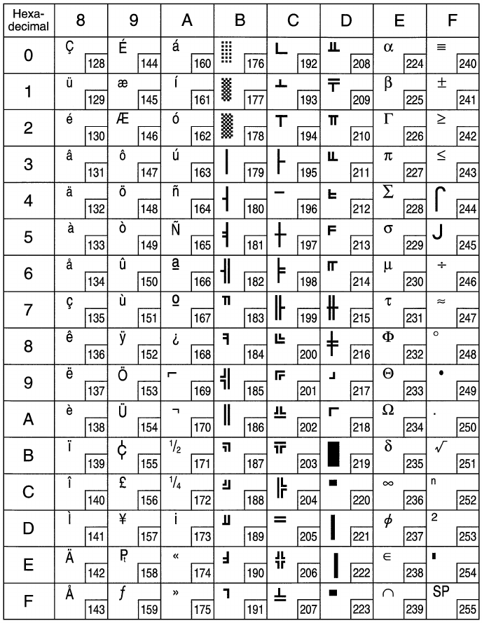
96
ESC/POS Mode
Page 0 (PC437)
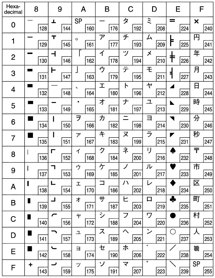
97
ESC/POS Mode
Page 1 (Katakana)
Note: Other characters are the same as those for Page 0.
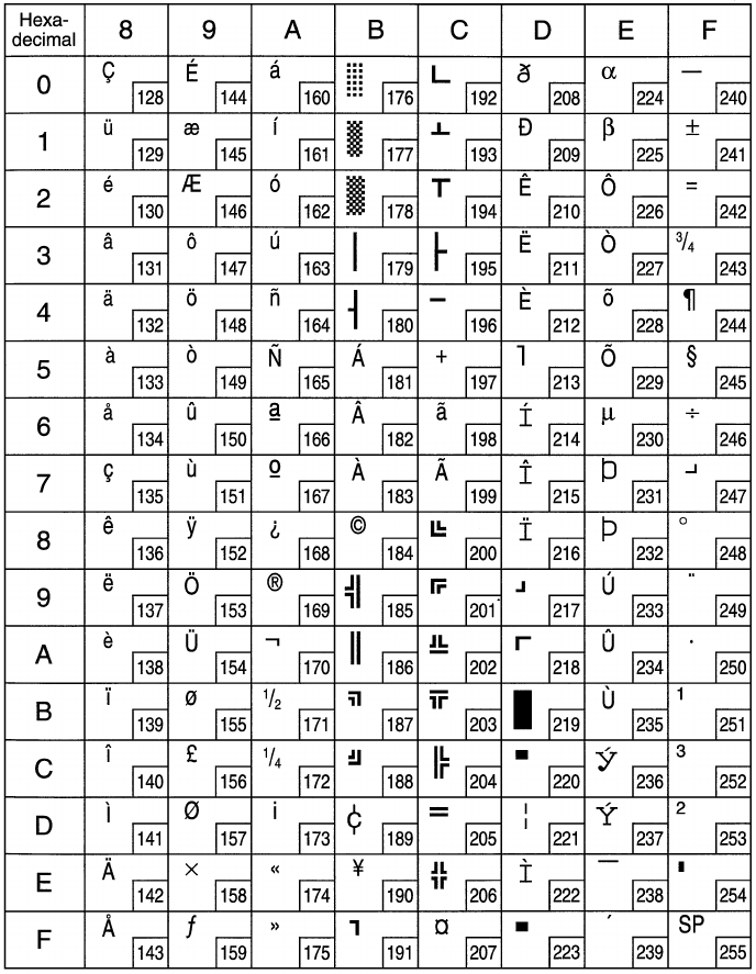
98
ESC/POS Mode
Page 2 (PC850: Multilingual)
Note: Other characters are the same as those for Page 0.
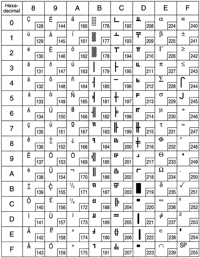
99
ESC/POS Mode (Receipt printer only)
Page 3 (PC860: Portuguese)
Note: Other characters are the same as those for Page 0.
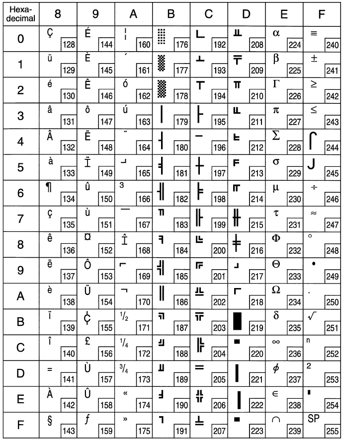
100
ESC/POS Mode (Receipt printer only)
Page 4 (PC863: Canadian-French)
Note: Other characters are the same as those for Page 0.
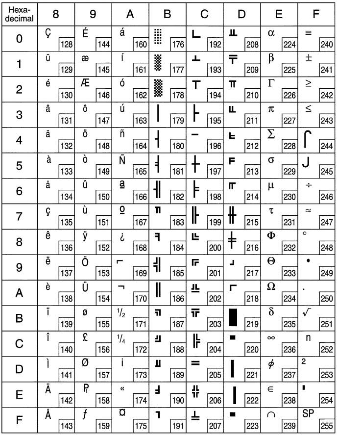
101
ESC/POS Mode (Receipt printer only)
Page 5 (PC865: Nordic)
Note: Other characters are the same as those for Page 0.
102
ESC/POS Mode (Receipt printer only)
Page 255 (Space Page)
Note: Other characters are the same as those for Page 0.
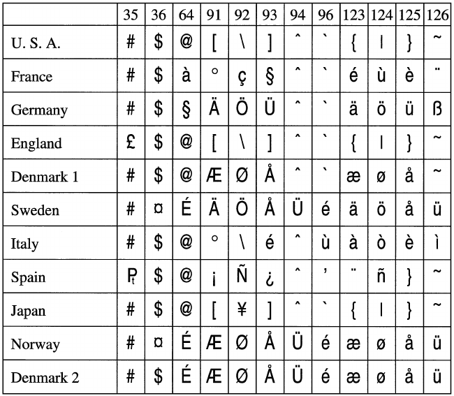
103
ESC/POS Mode
International Character Set

OVERSEAS SUBSIDIARY COMPANIES
STAR MICRONICS AMERICA, INC.
70-D Ethel Road West, Piscataway, NJ 08854 U.S.A
Tel: 732-572-9512, Fax: 732-572-5095
STAR MICRONICS U.K. LTD.
Star House, Peregrine Business Park, Gomm Road,
High Wycombe, Bucks, HP 13 7DL, U.K.
Tel: 01494-471111, Fax: 01494-473333
HEAD OFFICE
STAR MICRONICS CO., LTD.
536 Nanatsushinnya, Shimizu, Shizuoka
424-0066 Japan
Tel: 0543-47-0112, Fax: 0543-48-5271
Please access the following URL
http://www.star-micronics.co.jp/service/sp_sup_e.htm
for the lastest revision of the manual.
1998. 05. 16
Printed in Japan, 80872036
