Star Solutions 2-06-01-00-1 iCell DOrA Compact BTS Macro 1F 1900 MHz User Manual EVDO Portable IIC Guide
Star Solutions International Inc iCell DOrA Compact BTS Macro 1F 1900 MHz EVDO Portable IIC Guide
User Manual

All‐IPCDMA2000
®
Network
iCell®
CompactMacroEV‐DOBTS
InstallationandInitialConfiguration
Guide
PartNumberD02149A0

All‐IPCDMA2000
®
Network
iCell®
CompactMacroEV‐DOBTS
InstallationandInitialConfiguration
Guide
PartNumberD02149A0
Copyright©2008,GlobalStarSolutionsULC.Allrightsreserved.Nopartofthisdocumentationmaybereproducedinanyform
orbyanymeansorusedtomakeanyderivativework(suchastranslation,transformation,oradaptation)withoutpriorwritten
permissionfromGlobalStarSolutionsULC.
GlobalStarSolutionsULCreservestherighttorevisethisdocumentationandtomakechangesincontentfromtimetotime
withoutobligationonthepartofGlobalStarSolutionsULCtoprovidenotificationofsuchrevisionorchange.
GlobalStarSolutionsULCprovidesthisdocumentationwithoutwarrantyofanykind,eitherimpliedorexpressed,including,but
notlimitedto,theimpliedwarrantiesofmerchantabilityandfitnessforaparticularpurpose.StarSolutionsmaymake
improvementsorchangesintheproduct(s)and/ortheprogram(s)describedinthisdocumentationatanytime.
UNITEDSTATESGOVERNMENTLEGENDS:
IfyouareaUnitedStatesgovernmentagency,thenthisdocumentationandthesoftwaredescribedhereinareprovidedtoyou
subjecttothefollowing:
UnitedStatesGovernmentLegend:Alltechnicaldataandcomputersoftwareiscommercialinnatureanddevelopedsolelyat
privateexpense.SoftwareisdeliveredasCommercialComputerSoftwareasdefinedinDFARS252.227‐7014(June1995)orasa
commercialitemasdefinedinFAR2.101(a)andassuchisprovidedwithonlysuchrightsasareprovidedinStarSolutions's
standardcommerciallicensefortheSoftware.TechnicaldataisprovidedwithlimitedrightsonlyasprovidedinDFAR
252.227‐7015(Nov.1995)orFAR52.227‐14(June1987),whicheverisapplicable.You agreenottoremoveordefaceanyportion
ofanylegendprovidedonanylicensedprogramordocumentationcontainedin,ordeliveredtoyouinconjunctionwith,this
UserGuide.
StarSolutions,theStarSolutionslogo,iCell,Softexchange,Sonata,SonataAccessTandem,SonataHLR,SonataIP,SonataMSC,
SonataWLL,andTelo sareregisteredtrademarksortrademarksofGlobalStarSolutionsULCanditssubsidiaries.
CDMA2000®isaregisteredtrademarkoftheTelecommunicationsIndustryAssociation(TIA‐USA).
IntelandPentiumareregisteredtrademarksoftheIntelCorporationoritssubsidiariesintheUnitedStatesandothercountries.
Microsoft,Windows,WindowsNT,andNetMeetingareregisteredtrademarksofMicrosoftCorporation.Sun,Java,andSolaris
aretrademarksorregisteredtrademarksofSunMicrosystems,Inc.OracleisaregisteredtrademarkofOracleCorporation.HP,
HP‐UX,andHPOpenviewaretrademarksorregisteredtrademarksoftheHewlett‐PackardCompany.UTStarcom,theUTStarcom
logo,MovingMedia,mSwitch,andTota lControlareregisteredtrademarksortrademarksofUTStarcom,Inc.anditssubsidiaries.
Otherbrandandproductnamesmayberegisteredtrademarksortrademarksoftheirrespectiveholders.

StarSolutionsAll‐IPCDMA2000NetworkiCell PartNumberD02149A0
CompactMacroEV‐DOBTSInstallationandInitialConfigurationGuide October2008
CONTENTS
ABOUTTHISGUIDE
All‐IPCDMA2000®NetworkArchitecture ......................................11
ProductOverview.........................................................12
IPRadioAccessNetworkElements........................................13
BaseStationSubsystem .................................................13
RNC...............................................................13
CompactMacroBTS .................................................13
CompactMacroBTSHardwareSpecifications ............................14
GPS ...............................................................14
DirectGPSandDaisyChainofOnePPSsource ........................15
Conventions ..............................................................17
Notices ...............................................................17
FiguresandScreenCaptures .............................................17
Text ..................................................................17
RelatedDocumentation....................................................18
Technical Support .........................................................18
ObtainingTec hnicalAssistance ...........................................18
ServiceCentersOperationalHours.....................................19
WarrantySupport.........................................................19
ContactingTec hnicalDocumentation .........................................19
PARTIPRE-INSTALLATION
1PREREQUISITES
AboutThisChapter ........................................................23
SiteRequirements .........................................................23
EquipmentSuppliedbyNetworkOperator...............................23
InstallerRequirements.....................................................24
SkillsandKnowledge....................................................24
SupportingDocumentation ..............................................24
RequiredHandTools ....................................................24
Testin gRequirements......................................................24
TestClientHardware ....................................................24
Laptop ............................................................24
MobilePhone .........................................................25
Cables ................................................................25
NetworkPlanningRequirements .............................................25
IPAddressAssignment..................................................25
TestClient..........................................................26
AccessNetworkIPAddressing .........................................26

6
StarSolutionsAll‐IPCDMA2000NetworkiCell PartNumberD02149A0
CompactMacroEV‐DOBTSInstallationandInitialConfigurationGuide October2008
CoreNetworkIPAddressing...........................................26
HostnameAssignment..................................................27
PasswordandUsernameAssignment......................................27
PARTII INSTALLATION
2INSTALLINGTHECOMPACTMACROBTS
AboutThisChapter ........................................................31
UnpackingtheShipment ...................................................31
VerifyingCompactMacroBTSAirflowandVentilation ...........................32
InstallingtheCompactMacroBTS ............................................33
MaximumPermissibleExposureRequirements ..............................33
MountingtheCompactMacroBTS........................................33
ConnectingtheCompactMacroBTSFrontPanelInterface........................35
ConnectingtheCompactMacroBTSRearPanelInterface ........................35
ConnectingtheGPS.....................................................36
GPSConnectionGuidelines ...........................................36
GPSReceiverProtection ..............................................37
ConnectingaGPSCabletotheCompactMacroBTS.......................37
1PPSConnections...................................................37
ConnectingtheMainandDiversityAntennas................................38
BeforeConnectingRFCables..........................................38
ConnectingtheRFCables .............................................38
ConnectingACPowertotheCompactMacroBTS ............................38
SafetyAdvisory .....................................................38
ACPowerConnection ................................................39
AddingSectors............................................................39
MaintainingtheCompactMacroBTS .........................................39
FrontPanelLEDStatusLight...........................................39
ResetButton .......................................................40
ReplacingtheFanModule ............................................40
PARTIII INITIAL CONFIGURATION
3CONFIGURINGTHECOMPACTMACROBTS
AboutThisChapter ........................................................45
InitialSetup..............................................................45
ConfiguringaTestClient .................................................46
ConnectingtheTestClienttotheEthernetSwitch............................47
PerformingaPingTest ..................................................47
ConfiguringtheIPSwitch................................................47
ConfiguringtheLENOVOSwitch .......................................47
UpdatingtheRNCSoftwareandConfiguration ..............................48
ModifyingtheRNCandBTSConfigurationFiles ..............................49
ModifyingtheRNCConfiguration ......................................50

7
StarSolutionsAll‐IPCDMA2000NetworkiCell PartNumberD02149A0
CompactMacroEV‐DOBTSInstallationandInitialConfigurationGuide October2008
ModifyingtheBTSConfigurationFile ...................................50
ConfiguringtheBTSBAPIP..................................................51
ConfiguringtheBTS(s)......................................................51
ConfiguringtheSerialConnectiontotheBTS ................................51
PARTIV APPENDICES
AREGULATORYNOTICES
U.S.RegulatoryStatement..................................................57
CanadianRegulatoryStatement .............................................57
RFExposureMPEExhibit ...................................................57
BACRONYMSANDABBREVIATIONS

8
StarSolutionsAll‐IPCDMA2000NetworkiCell PartNumberD02149A0
CompactMacroEV‐DOBTSInstallationandInitialConfigurationGuide October2008
LISTOFTABLES
Table1 HardwareSpecifications ..........................................14
Table2 NetworkInterfaces...............................................14
Table3NoticeIconDescriptions ..........................................17
Table4TextConventionDescriptions ......................................17
Table5 CablesandAntennasSuppliedbytheNetworkOperator................23
Table6RequiredToolsforInstallation......................................24
Table7TestClientRequirements ..........................................24
Table8RequiredCables .................................................25
Table9RequiredIPAddressingforTestClient ...............................26
Table10 RequiredIPAddressingforEthernetSwitch...........................26
Table11 RequiredIPAddressingforRNC ....................................26
Table12 RequiredIPAddressingforBTS .....................................26
Table13 RequiredIPAddressingforCoreNetwork............................26
Table14 LoginConfigurationforSite(telnet).................................27
Table15 CompactMacroBTSFrontPanelInterfaceConnections.................35
Table16 ExampleofBTSWiring ............................................36
Table17 FrontPanelLEDStatusLight .......................................40
Table18 FactoryDefaultIPConfigurationPlan................................45
Table19 SerialBaudRates ................................................47
Table20 bsc.cfgConfiguration.............................................50
Table21 bts.cfgConfiguration .............................................51
Table22 ListofAcronyms .................................................59

9
StarSolutionsAll‐IPCDMA2000NetworkiCell PartNumberD02149A0
CompactMacroEV‐DOBTSInstallationandInitialConfigurationGuide October2008
LISTOFFIGURES
Figure1All‐IPCDMA2000
©
EV‐DONetworkArchitecture......................12
Figure2ExternalFrontViewoftheCompactMacroBTS.......................15
Figure3ExternalRearViewoftheCompactMacroBTS.......................15
Figure4ExternalSideViewoftheCompactMacroBTS........................16
Figure5TopViewofCompactMacroBTSAirflow............................32
Figure6RearViewofInstallingtheCompactMacroBTS.......................34
Figure7CompactMacroBTSFrontPanel...................................35
Figure8CompactMacroBTSRearPanel....................................36
Figure9FanModule:CaptivePanelFastenerLocation........................40
Figure10ConnectionDiagram.............................................46
Figure11ExampleofTheChangeCommand.................................53

10
StarSolutionsAll‐IPCDMA2000NetworkiCell PartNumberD02149A0
CompactMacroEV‐DOBTSInstallationandInitialConfigurationGuide October2008
StarSolutionsAll‐IPCDMA2000®NetworkiCell PartNumberD02149A0
CompactMacroEV‐DOBTSInstallationandInitialConfigurationGuide October2008
ABOUTTHISGUIDE
ThischaptercontainsanoverviewofthisguideandanoverviewoftheiCell®
CompactMacroBaseTransceiverStation(CompactMacroBTS).Thischapteralso
listsguideconventionsandrelateddocumentation,anddescribeshowtocontact
customerserviceandtechnicaldocumentation.
ThisguideisintendedforthosewhomustinitiallyconfiguretheCompactMacro
BTS.
Thischapterincludes:
■All‐IPCDMA2000®NetworkArchitecture
■ProductOverview
■Conventions
■RelatedDocumentation
■TechnicalSupport
■WarrantySupport
■ContactingTechnicalDocumentation
Releasenotesareissuedwithsomeproducts.Iftheinformationintherelease
notesdiffersfromtheinformationinthisguide,followtheinstructionsinthe
releasenotes.
All‐IPCDMA2000®Network
Architecture
TheCompactMacroBTSispartoftheGlobalStarSolutionsULC(StarSolutions)
All‐IPCDMA2000®NetworkforCDMA2000©RadioAccessNetworks.
TheAll‐IPCDMA2000®Networkisanend‐to‐end,all‐Internet‐Protocol
(IP)‐based,wirelesscommunicationsolution.TheAll‐IPCDMA2000®Network
providesthemobilityandmedia‐controltraditionallyassociatedwitha
circuit‐switchedMobileSwitchingCenter(MSC),butinapacket‐based
environment.
TheAll‐IPCDMA2000®Networkissecond‐generation(2G)andthird‐generation
(3G)capable,supportingCDMAOneandCDMA2000©1xandEvolutionData
Optimized(EV‐DO)networks.BydeployingtheAll‐IPCDMA2000®Networkin2G
and3Genvironments,networkoperatorsgaintheefficiencyinherentin
packet‐basednetworks,whilebuildinganetworkcorecapableofsupporting3G
standards.
12 AboutThisGuide
StarSolutionsAll‐IPCDMA2000®NetworkiCell PartNumberD02149A0
CompactMacroEV‐DOBTSInstallationandInitialConfigurationGuide October2008
All‐IPCDMA2000®Networkbenefitsinclude:
■Anetworkcorethatsupportsbothvoiceanddatatraffic,eliminatingtheneed
tooperateseparateTimeDivisionMultiplexing(TDM)andpacketbackbones.
■Distributedswitchingforefficientcall‐routingfromendpointtoendpoint.
■Centralizedcontrolofdistributedswitchingforcost‐effectivescalability,
security,andeaseofoperation.
■Voicecarriedinnativeair‐interfaceformatacrossthepacketcorefor
maximumbandwidthefficiency,withPulseCodeModulation(PCM)vocoding
donebytheMediaGatewaysatthenetworkedgeforPublicSwitched
TelephoneNetwork(PSTN)connectivity.
■SupportsANSIIS‐41requirements
■3GarchitectureforCDMA2000©1x
■3GarchitectureforEV‐DO.
TheAll‐IPCDMA2000®Networkenablestheevolutiontoanall‐IPnetworkwhile
deliveringareducedcostofconstructionandownershipcomparedtotraditional
TDMnetworks.
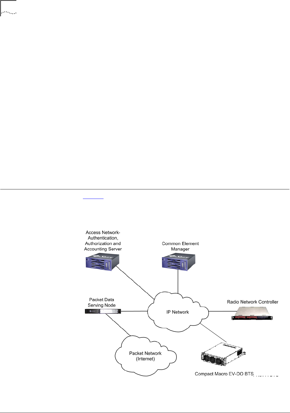
ProductOverview Figure1showsahigh‐levelarchitectureexamplefortheAll‐IPCDMA2000®
Network,includingtheRadioNetworkController(RNC)andCompactMacroBTS
NetworkElements.
Figure1All‐IPCDMA2000
©
EV‐DONetworkArchitecture

ProductOverview 13
StarSolutionsAll‐IPCDMA2000®NetworkiCell PartNumberD02149A0
CompactMacroEV‐DOBTSInstallationandInitialConfigurationGuide October2008
IPRadioAccessNetwork
Elements
TheIPRadioAccessNetworkElementsinclude:
■Authentication,AuthorizationAndAccountingServer
■CommonElementManager
■PacketDataServingNode
■PacketNetwork(Internet)
■IPNetwork
■RNC
■CompactMacroBTS.
BaseStationSubsystemAnRNCandtheassociatedBTS(s)areknowncollectivelyasaBaseStation
Subsystem(BSS).
RNC
TheRNCmanagescallcontrolandinterconnectionstotheothernetwork
elements.
TheRNCapplicationissupportedbyanoperatingsystemthatalsoprovides
platformservices.WhiletheRNChasseveralphysicalplatforms,eachphysical
platformrunsthesameRNCapplicationandplatformservices.
TheCompactMacroBTScommunicateswiththeRNCoveranEthernetIP
connection.RNCserversareco‐located,orcentralizedatanyconvenient
location.
ThisguidedoesnotdescribeallRNCconfigurations,whichvarybasedonnetwork
andoperatorrequirements.
CompactMacroBTS
TheCompactMacroBTSprovidesIP‐basedcoverageforCDMA2000©3Gwireless
networks.ThisBTSinterfacesbyIPtothestandardiCellsoftRNC.TheAll‐IP
CDMA2000®Networkdistributedarchitecture,eliminatestheneedtocarry
traffictoacentralRNC,reducingoperationalcomplexity.TheCompactMacroBTS
sharesthesameinternalhardwareasthestandardiCellMacrosystem.Theonly
differenceisthatallthecomponentsforonesectorarehousedinasinglecasing
allowingforaverycompactinstallation.TheCompactMacroBTSisidealfor
portablesystems,disasterrecoverysystemsandforruralareaswheretrafficis
notanticipatedtogrowbeyondonecarrierandthreesectors(1F/3S).
Themainunitalsosupportstheadditionoftwomoresectorunits.Eachsector
unitcomesina2U‐high,19in.,rack‐mountedchassis.Thismodular,flexible
designenableswirelessoperatorstostartsmallwithasinglesectorandallows
additionalsectorstobeaddedinthefuturetotriplecapacity.

14 AboutThisGuide
StarSolutionsAll‐IPCDMA2000®NetworkiCell PartNumberD02149A0
CompactMacroEV‐DOBTSInstallationandInitialConfigurationGuide October2008
Caution:
CompactMacroBTSHardwareSpecifications
Table1liststheCompactMacroBTShardwarespecifications.
Althoughthepowerclassofthisequipmentisgeneralizedas20watts,theactual
RFoutputpowermayexceedthislevelandinsomeinstancesbeashighas25
wattsorgreater.Referencesinthisguidetopoweroutputlevelsof20wattsare
typical;thisstatementappliesinallreferencestothistypicallevel.
:
Theinformationcontainedhereinisforinformationalpurposesonly.Technical
claimslisteddependonaseriesoftechnicalassumptions.Yourexperiencewith
theseproductsmaydifferifyouoperatetheproductsinanenvironment,whichis
differentfromthetechnicalassumptions.StarSolutionsreservestherightto
modifythesespecificationswithoutpriornotice.StarSolutionsmakesno
warranties,expressorimplied,ontheinformationcontainedinthisdocument.
GPS
ThefollowingGPS‐producedsignalsareusedforeachBTSwhenSoftorHard
Handoffsarerequired:
■TimeofDay(ToD)message
■Synchronized1PulsePerSecond(1PPS)
Table1HardwareSpecifications
RFOutputPower 20wattsatantennaport
RxSensitivity ‐128dBm
Inputvoltage 110‐240VAC
Powerconsumption 450wattsfor1F/3SwithsRNC
Dimensions 3Urackspaces(approximately5.25in.(13.33cm)high,19in.
(48.26cm)wide,and24in.(60.96cm)deep)
Weight 25kg
Operatingtemperature 0°to+40°C
Storagetemperature ‐40to+60°C
Humidity 5‐95%non‐condensing
AntennaConnectors Two7‐16DINFemale(fordiversityreceive)
TransportationShockand
Vibration
MeetsTelcordiaSpecificationGR‐63‐CORE
EnvironmentallyInduced
Vibration
MeetsTelcordiaSpecificationGR‐487‐CORE
altitudeMax 10000ft.
Table2NetworkInterfaces
Ethernet(10/100BASE‐T)
SNMPv2c
ProductOverview 15
StarSolutionsAll‐IPCDMA2000®NetworkiCell PartNumberD02149A0
CompactMacroEV‐DOBTSInstallationandInitialConfigurationGuide October2008
DirectGPSandDaisyChainofOnePPSsource
Forin‐buildinginstallations,theGPSreceiverisconnectedtooneBTS(thefirst
BTS)ineachcluster,directlythroughthe1PPSINSMAconnectorandtheRS232
ToDport.The1PPSsignalcanbeextendedbycoaxialcabletoothernearbyBTS
unitsusingthe1PPSOUTportofthefirstBTSgoingtothe1PPSINportofthe
nextBTS.
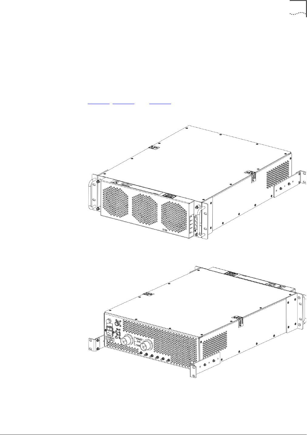
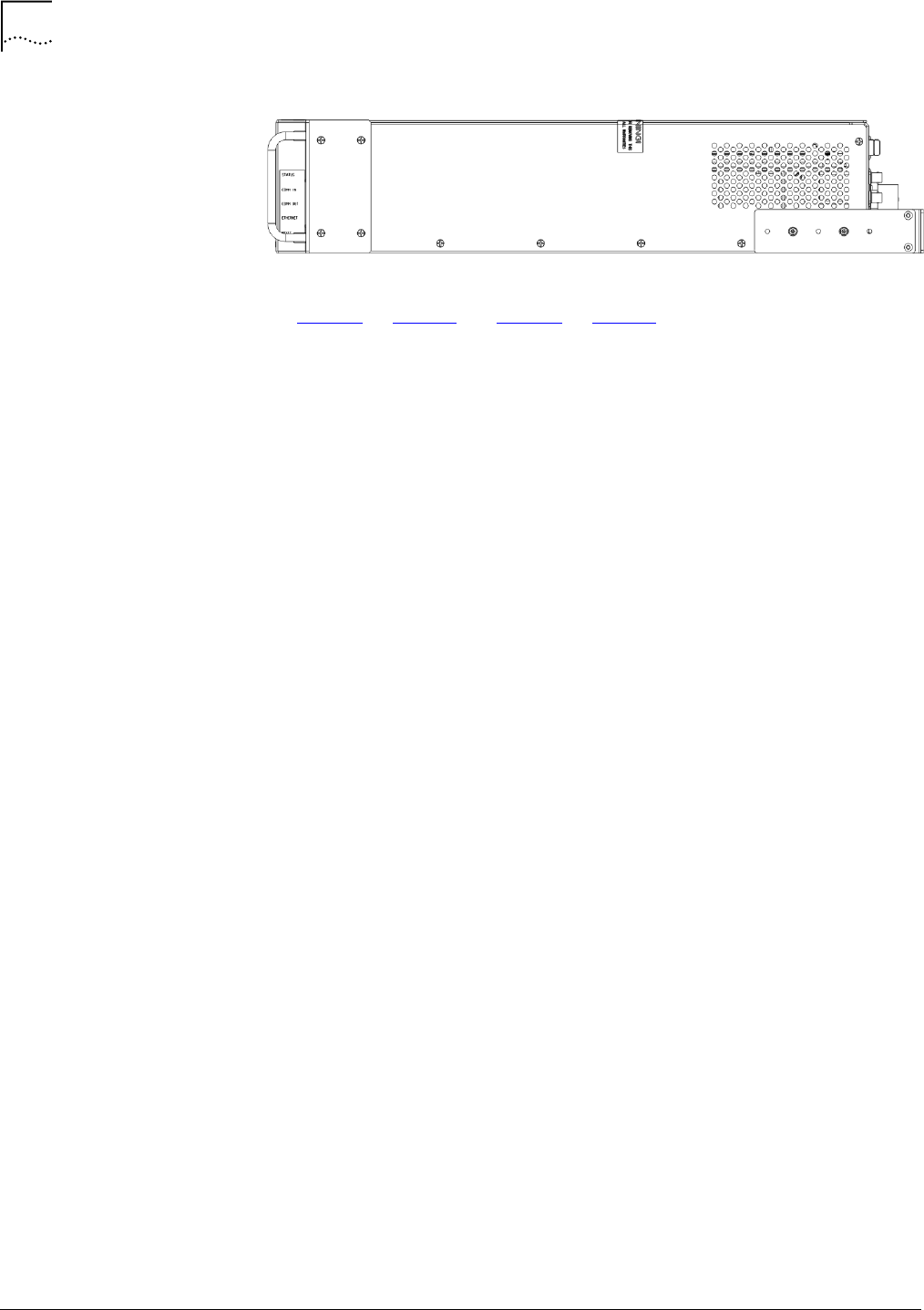
Figure2,Figure3,andFigure4showexternalviewsoftheCompactMacroBTS.
Figure2ExternalFrontViewoftheCompactMacroBTS
Figure3ExternalRearViewoftheCompactMacroBTS
16 AboutThisGuide
StarSolutionsAll‐IPCDMA2000®NetworkiCell PartNumberD02149A0
CompactMacroEV‐DOBTSInstallationandInitialConfigurationGuide October2008
Figure4ExternalSideViewoftheCompactMacroBTS
SeeFigure7onpage35andFigure8onpage36foridentificationofthe
CompactMacroBTSinputandoutputconnections.

Conventions 17
StarSolutionsAll‐IPCDMA2000®NetworkiCell PartNumberD02149A0
CompactMacroEV‐DOBTSInstallationandInitialConfigurationGuide October2008
Conventions Thisguidemaycontainnotices,figures,screencaptures,andcertaintext
conventions.
Notices Table3listsnoticeiconsusedinthisguide.
.
FiguresandScreenCaptures Thisguideprovidesfiguresandscreencapturesasexamples.Theseexamples
containsampledata.Thisdatamayvaryfromtheactualdataonaninstalled
system.
Text Table4liststextconventionsinthisguide.
Table3NoticeIconDescriptions
Icon NoticeType Description
InformationNote Informationthatcontainsimportantfeaturesor
instructionsbutisnothazard‐related.
CautionorWarning CautionsareprecededwiththewordCaution.Thistypeof
cautionindicatesapotentiallyhazardoussituationwhich,if
notavoided,mayresultinminorormoderateinjury.Itmay
alsoalertagainstunsafepracticesandpotentialprogram,
data,system,ordevicedamage.
WarningsareprecededwiththewordWarning.Thistype
ofwarningindicatesapotentiallyhazardoussituation
which,ifnotavoided,couldresultindeathorserious
injury.
CautionorWarning
duetopotential
electricalhazard
Cautionsduetopotentialelectricalhazardsarepreceded
withthewordCaution.Thistypeofcautionindicatesa
potentialelectricalhazard.Thishazard,ifnotavoided,may
resultinminorormoderateinjury.Itmayalsoalertagainst
unsafepracticesandpotentialprogram,data,system,or
devicedamage.
Warningsduetopotentialelectricalhazardsarepreceded
withthewordWarning.Thistypeofwarningindicatesa
potentialelectricalhazard.Thishazard,ifnotavoided,
couldresultindeathorseriousinjury.
ESD Informationthatindicatespropergroundingprecautions
arerequiredbeforehandlingaproduct.
Table4TextConventionDescriptions
Convention Description
Textrepresentedasascreen
display
This typefacerepresentstextthatappearsonaterminal
screen,forexamplelogin:.
Textrepresentedasuser
entry.
Thistypefacerepresentscommandsenteredbytheuser,for
example,cd$HOME.
Textrepresentedasmenus,
sub‐menus,buttons,tabs,
directories,andfieldnames
Thistypefacerepresentsallmenus,sub‐menus,buttons,tabs,
directories,andfieldnameswithinprocedures,forexample:
OntheFilemenu,clickNew.
Textrepresentedby<variable>Thistypefacerepresentsarequiredvariable,forexample:
<filename>

18 AboutThisGuide
StarSolutionsAll‐IPCDMA2000®NetworkiCell PartNumberD02149A0
CompactMacroEV‐DOBTSInstallationandInitialConfigurationGuide October2008
RelatedDocumentation TheCompactMacroBTSispartoftheAll‐IPCDMA2000®Networkproductline
forCDMA2000©.TheCompactMacroBTSdocumentationispartofthe
documentationfortheAll‐IPCDMA2000®Networkproductline.
Thefollowingdocumentscontaininformationonhowtoinstall,operate,and
maintaintheCompactMacroBTS.
■iCellAllIPRANCDMAEV‐DOReleaseNotes
■iCellCompactMacroEV‐DOBTSInstallationandInitialConfigurationGuide
■iCellAllIPRadioAccessNetworkOperationandMaintenanceGuide
■iCellBaseStationSubsystemParameterReference.
TechnicalSupport TheStarSolutionsProductSupportTeamdeliversthesupportservicesrequired
forbusinessandprofessionalneeds.OurproductexpertsdeliverTier1,2and3
technicalsupportdirectlytonewandcontract‐entitledcustomersincludingthe
followingservices:
■BasicSupportPackage:Non‐emergencytechnicalsupport
■PremiumSupportPackage:24hoursaday,7daysaweek,365daysayear,
emergencytechnicalsupport.
TheStarSolutionsServiceGuideoutlinesthespecificdetailsforobtaining
technicalsupport.Theguideisavailablefromasalesaccountmanager.Referto
theserviceguideforservicesandoptionsspecifictoindividualsupportplans,
includingguidelinesforproblemseverityandthetechnicalresolutionescalation
process.
ObtainingTechnical
Assistance
StarSolutionsmaintainsaglobalpresencethroughitsTechnicalResponseand
ServiceCenters.Thesecentersareavailablefortechnicaltelephonesupportto
entitledcustomersduringnormalbusinesshours.
Beforecontactingtechnicalsupport,havethisinformationavailable:
■Productinformation
■Softwareandhardwarerevisions
■Serialnumbers
■Problemdescription
■Symptoms
■Knowncauses
■Troublelocatingandclearingattempts.
Forinformationaboutcustomerservice,includingsupport,training,code
releasesandupdates,contracts,anddocumentation,contactusat:
http://www.starsolutions.com/support

WarrantySupport 19
StarSolutionsAll‐IPCDMA2000®NetworkiCell PartNumberD02149A0
CompactMacroEV‐DOBTSInstallationandInitialConfigurationGuide October2008
ServiceCentersOperationalHours
■NorthAmerica/CALARegion:
■09:00–18:00PacificTime(UTC‐8:00)
■EMEA/AsiaPacificRegion:
■09:30–18:30IndianStandardTime(UTC+5:30)
WarrantySupport StarSolutionsprovidesitscustomerswarrantysupportperthetermsoftheStar
SolutionsWarrantyStatementfortheirequipment.Customerswhorequire
warrantysupportshouldcontacttheStarSolutionsCustomerServiceCenteras
specifiedinthecustomerserviceguideorat:
http://www.starsolutions.com/support
ContactingTechnical
Documentation
Toprovidecommentsonthisdocumentation,sendane‐mailto:
dl‐techcom@starsolutions.com
Pleaseincludethenameandpartnumberoftheguidebeingreferenced.If
applicable,providethechapterandpagenumber.

20 AboutThisGuide
StarSolutionsAll‐IPCDMA2000®NetworkiCell PartNumberD02149A0
CompactMacroEV‐DOBTSInstallationandInitialConfigurationGuide October2008
StarSolutionsAll‐IPCDMA2000NetworkiCell PartNumberD02149A0
CompactMacroEV‐DOBTSInstallationandInitialConfigurationGuide October2008
1PREREQUISITES
AboutThisChapter Thischapterdescribesinstallationprerequisitesthatmustbeinplacebefore
installationbegins.
Thischapterincludes:
■SiteRequirements
■InstallerRequirements
■TestingRequirements
■NetworkPlanningRequirements
SiteRequirements Thenetworkoperatorisresponsibleforsupplyingsupportingcomponents,
cabling,andthenecessaryoperatingenvironmentfortheCompactMacroBTS.
EquipmentSuppliedbyNetworkOperator
ThecompactMacroBTSrequiresaminimum3U,19‐inch(48.26cm)wide
equipmentrack.
Thenetworkoperatorisresponsibleforsitegroundingandlightningprotection.
Verifyallgrounding,powerconnections,andlightningprotectionmeetorexceed
localstandards.
Table5listscablesandantennassuppliedbythenetworkoperatortosupport
theinstallationandoperationoftheCompactMacroBTS.
Table5CablesandAntennasSuppliedbytheNetworkOperator
Cable Description
CellularSectorAntenna MainandDiversitysectorantenna(20Wattoutput)
PowerCable RefertoInstallationsectionfordetails(InstallingtheCompact
MacroBTS)
EthernetCable CAT‐5Ethernetcablewith2RJ‐45connectorends.
RFCables CorrugatedcableswithN‐type(male)connectorstoconnect
sectorsexpansionBTSandexternalGPSantennas(if
required).
AntennaCableCorrugatedRFcablewithDIN7/ 1 6 plug(male)connector.(50
ohmimpedance,3GHzminimuminterfacefrequencyand
ratedforminimum50Wattat2GHz)
GroundingCable #2AWGwire

24 Chapter1:Prerequisites
StarSolutionsAll‐IPCDMA2000NetworkiCell PartNumberD02149A0
CompactMacroEV‐DOBTSInstallationandInitialConfigurationGuide October2008
InstallerRequirements Thissectionincludes:
■SkillsandKnowledge
■SupportingDocumentation
■RequiredHandTools
SkillsandKnowledge TheinstallerofaCompactMacroBTSmusthavegeneraltelecommunications
andelectricalcircuitknowledge.
SupportingDocumentation Thisdocumentprovidesallthenecessaryinformationtoinstall,configure,
integrate,andtestaCompactMacroBTS.Nootherdocumentsarerequired.
TheNetworkPlanningdocument(engineeringspecificationsforthesiteand
network)isrequiredforanyconfigurationofCDMA2000©parametersafter
installationandinitialconfiguration.TheNetworkPlanningdocumentalso
providesthenecessaryinputstoNetworkPlanningRequirements.
ThedocumentsintheiCell®documentationsetarelistedinRelated
Documentationonpage18.
RequiredHandTools ThetoolsrequiredfortheinstallationoftheCompactMacroBTSarelistedin
Table6.
TestingRequirements Thissectionincludes:
■TestClientHardware
■Cables
TestClientHardwareThissectionincludes:
■Laptop
Laptop
AlaptopPC,knownasthetestclient,isrequiredfortheinstallation,
configuration,verification,andnetworkintegrationoftheCompactMacroBTS.
Table7liststherecommendedrequirementsforthetestclient.
Table6RequiredToolsforInstallation
Tool
StandardToolKit
1in‐lbs.SMATorqueWrench
Table7TestClientRequirements
Component Minimum Recommended
Processor 1.0GHz 1.3GHz

NetworkPlanningRequirements 25
StarSolutionsAll‐IPCDMA2000NetworkiCell PartNumberD02149A0
CompactMacroEV‐DOBTSInstallationandInitialConfigurationGuide October2008
MobilePhone Amobilephoneisrequiredformakingtestcalls.
Verifythatasuitabledatacableisavailableforthemobileusedinmaking
loopbacktestcalls.
Cables Severalcablesarerequiredthroughouttheconfigurationandverification
process.Table8liststhecablesrequiredfortheCompactMacroBTSinstallation,
configuration,andverificationprocess.
NetworkPlanning
Requirements
Thissectionincludes:
■IPAddressAssignment
■HostnameAssignment
■PasswordandUsernameAssignment
IPAddressAssignment Thissectionincludes:
■TestClient
■AccessNetworkIPAddressing
■CoreNetworkIPAddressing
OperatingSystem Microsoft®Windows®XP
ProfessionalEdition
Microsoft®Windows®XP
ProfessionalEdition
Memory 256MB 512MB
HardDrive 10GB 10GB
CDROMDrive 24X 48X
SerialPort Standard Standard
USBPort Optional Optional
EthernetPortandCard 10/100 10/100
Table7TestClientRequirements(continued)
Component Minimum Recommended
Table8RequiredCables
Cable Description
EthernetCable CAT‐5straightEthernetcablewith2RJ‐45connectorends.(Approximately
3Minlength.)
EthernetCable CAT‐5crossoverEthernetcablewith2RJ‐45connectorends.
(Approximately3Minlength.)
SerialCable Standardserialcablewith1maleDB‐9connectorendand1femaleDB‐9
connectorend.(Approximately3Minlength.)
DataCable DatacablewithonestandardUSBconnectorendanddataconnectorend
tomobilephone.

26 Chapter1:Prerequisites
StarSolutionsAll‐IPCDMA2000NetworkiCell PartNumberD02149A0
CompactMacroEV‐DOBTSInstallationandInitialConfigurationGuide October2008
TestClient
ThetestclientisusedtoconnecttotheNetworkElements,andmustbeonthe
samesubnet.TherequiredIPaddressinginformationforthetestclientislistedin
Table9.
AccessNetworkIPAddressing
Table10,Table11,andTable12listtheIPaddressinginformationrequiredfor
theAccessNetwork.
CoreNetworkIPAddressing
Table13liststheIPaddressinginformationrequiredforCoreNetwork
integration(PDSN/HA).
Table9RequiredIPAddressingforTestClient
TestClient
IPaddress1
Subnetmask1
Defaultgateway1
IPaddress2
Subnetmask2
Defaultgateway2
Table10RequiredIPAddressingforEthernetSwitch
EthernetSwitch
SwitchIPAddress
SubnetMask
DefaultGateway
Table11RequiredIPAddressingforRNC
RNC
RNCIPAddress
Table12RequiredIPAddressingforBTS
BTS
BTS1IPAddress
BTS2IPAddress
BTS3IPAddress
BTS4IPAddress
Table13RequiredIPAddressingforCoreNetwork
CoreNetwork
MSCIPAddress
PDSNIPAddress

NetworkPlanningRequirements 27
StarSolutionsAll‐IPCDMA2000NetworkiCell PartNumberD02149A0
CompactMacroEV‐DOBTSInstallationandInitialConfigurationGuide October2008
HostnameAssignment Thissectionincludes:
■PasswordandUsernameAssignment
PasswordandUsername
Assignment
TheCompactMacroBTScomponentshavedefaultusernameandpasswords
configured.TheBSScomponentscanbeassignednewsite‐specificusernames
andpasswordsduringinstallationandconfiguration,ornewusernamesand
passwordscanbeconfiguredlaterbytheoperator.
ContactStarSolutionssupportengineeringfordefaultpasswordinformation.
Table14liststheBSScomponentsthatrequireausernameandpasswordto
connect.Havethesite‐specificusernamesandpasswordsreadybefore
installationbeginssothatlogininformationcanbechangedtosite‐specific
values.
Changingusernamesandpasswordsisnotmandatory,butsite‐specificvalueswill
berequiredifusernamesandpasswordsarechanged.
TheusernameandpasswordfortheCoreNetworkElements(MSC,PDSN)arenot
sethere,buttheymustbeavailabletoenableconnectionduringtestcalls.
Table14LoginConfigurationforSite(telnet)
BSSComponent
Default
Username DefaultPassword SiteUsername SitePassword
EthernetSwitch ContactStarSolutions
supportengineeringfor
passwordinformation.
<site‐specific> <site‐specific>
RNC utdora ContactStarSolutions
supportengineeringfor
passwordinformation.
<site‐specific> <site‐specific>
BTS utdora ContactStarSolutions
supportengineeringfor
passwordinformation.
<site‐specific> <site‐specific>
MSC msc ContactStarSolutions
supportengineeringfor
passwordinformation.
<site‐specific> <site‐specific>
PDSN ContactStarSolutions
supportengineeringfor
passwordinformation.
<site‐specific> <site‐specific>

28 Chapter1:Prerequisites
StarSolutionsAll‐IPCDMA2000NetworkiCell PartNumberD02149A0
CompactMacroEV‐DOBTSInstallationandInitialConfigurationGuide October2008
StarSolutionsAll‐IPCDMA2000NetworkiCell PartNumberD02149A0
CompactMacroEV‐DOBTSInstallationandInitialConfigurationGuide October2008
2INSTALLINGTHECOMPACTMACROBTS
Warning:
Warning:
AboutThisChapter ThischapterdescribeshowtoinstalltheCompactMacroBTS.
TheCompactMacroBTSisdesignedtobeinstalledinastandard,7ft.(213.36
cm)tall,19in.(48.26cm)wide,equipmentrack.Topreventdamage,refertothe
instructionspackagedwiththedesiredrack.
Thischapterincludes:
■UnpackingtheShipment
■VerifyingCompactMacroBTSAirflowandVentilation
■InstallingtheCompactMacroBTS
■ConnectingtheCompactMacroBTSFrontPanelInterface
■ConnectingtheCompactMacroBTSRearPanelInterface
■AddingSectors
■MaintainingtheCompactMacroBTS
UnpackingtheShipment Inspectthepackingcontainerimmediatelyonarrivalattheinstallationsiteto
verifythatnodamagehasoccurredduringshipment.
TheCompactMacroBTSmayexceedlocalweight‐handlingguidelinesforasingle
person.BeforeinstallingtheCompactMacroBTS,verifysufficientpersonnelare
availabletoassistintheunloading,handling,andinstallationprocess.
Donotopencasing.Nouserserviceablepartsareinside.Referservicingto
qualifiedservicepersonnel.
Ifanydamageisobserved,notifytheshipperimmediatelytobegintheinsurance
claimprocess.Donotopenorunpackthecontaineruntilaninsuranceadjuster
hasinspectedthecontainersforexteriordamage.
Ifthecontainerappearstobeinsatisfactorycondition,openitandcarefully
unpacktheequipment.Verifythecontentsandquantitiesagainstthepacking
list.NotifyStarSolutionsimmediatelyifanydiscrepanciesarediscovered,to
verifywhetherthecompleteshipmenthasbeenreceived.
Donotdiscardtheshippingcarton.Theshippingcartonshouldbeusedifunits
arereturnedforrepairandreplacement.
32 Chapter2:InstallingtheCompactMacroBTS
StarSolutionsAll‐IPCDMA2000NetworkiCell PartNumberD02149A0
CompactMacroEV‐DOBTSInstallationandInitialConfigurationGuide October2008
Warning:
Warning:
Caution:
VerifyingCompactMacro
BTSAirflowandVentilation
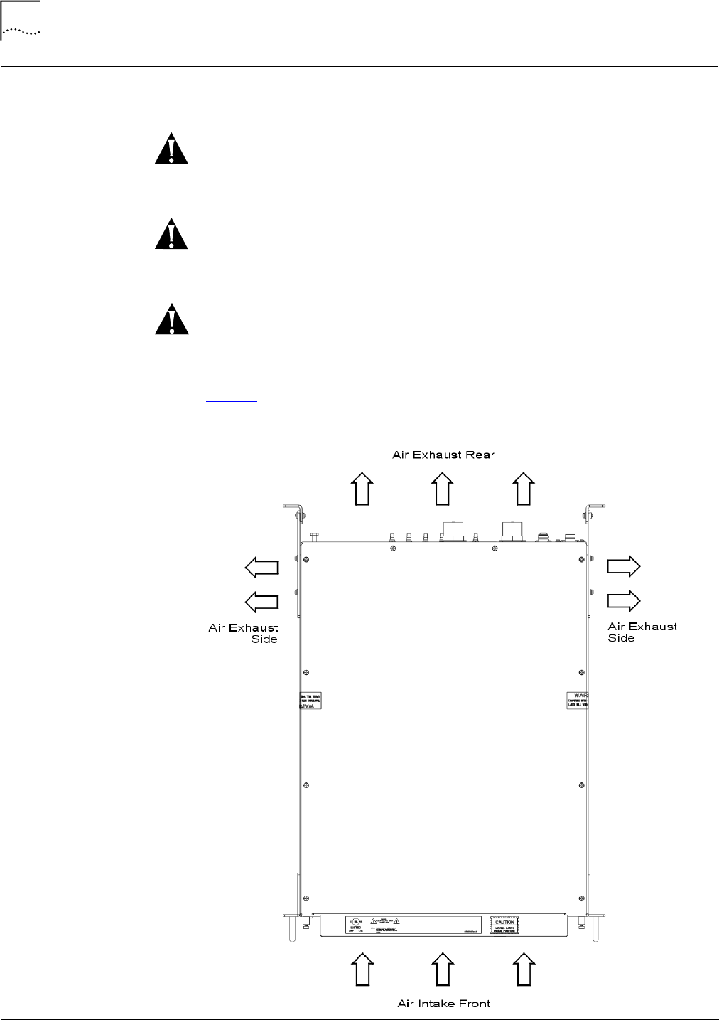
MaintainingsufficientairflowthroughtheCompactMacroBTSisrequiredfor
propersystemoperationandtoprotectsystemcomponentsfromoverheating.
Donotblockairvents,intakeandexhaust.Rearofunitmustbe6in.(152mm)
awayfromwallstoprovidesufficientairflow.
SurroundingequipmentexhaustmustnotfeedintotheCompactMacroBTSair
intakepanels.
FailuretoensureproperventilationandairflowthroughtheCompactMacroBTS
canresultindegradedsystemperformanceordamagetothecomponents.
Figure5displaystheairflowdirectionthroughtheCompactMacroBTS.
Figure5TopViewofCompactMacroBTSAirflow
InstallingtheCompactMacroBTS 33
StarSolutionsAll‐IPCDMA2000NetworkiCell PartNumberD02149A0
CompactMacroEV‐DOBTSInstallationandInitialConfigurationGuide October2008
Warning:
Warning:
InstallingtheCompact
MacroBTS
ThissectiondescribeshowtoinstalltheCompactMacroBTSina19in.
equipmentrack.
Usetherackbreakerstostoppowertotherackbeforeremovingorinstallingthe
CompactMacroBTS.
Verifytheunitisproperlygrounded,usingtheprovidedgroundstudontherear
panel(seeFigure8).Failuretoinstallpropergroundingmaycausepersonalinjury
and/ordamagetoequipment.
SeeTable1onpage14forhardwarespecifications.
MaximumPermissible
ExposureRequirements
TocomplywiththeMaximumPermissibleExposure(MPE)requirements,the
maximumpowerdensityresultingfromthecompositeEffectiveIsotopicRadiated
Power(EIRP)fromtheantennaconnectedtothisequipmentmustbesuchthat
exposureislimitedtoamaximumof1mW/cm2.
ThisvaluecanbeachievedbymultiplecombinationsofRFoutput,antennagain,
anddistancefromtheantennawhenenergized.
TheMPEisexpressedasfollows:
PowerDensityPd(mW/cm2)=EIRP/4d2
Whered=distancefromtheantenna.
Asanexample,withthetransmitterrunningat20Woutputintoanantennawith
againof10dBi,theminimumsafedistancefromtheantennatoinsurethat
exposureremainsbelow1mW/cm2wouldbe126cm.
Wheninstalling,theaboverelationshipshouldbeusedtoinsurethecombination
ofpower,antennagain,anddistancearesuchthatthemaximumpermissible
powerdensityof1mW/cm2isnotexceeded.Differentcombinationsofoutput
powerandantennagainwillresultindifferentminimumsafedistances.
MountingtheCompactMacro
BTS
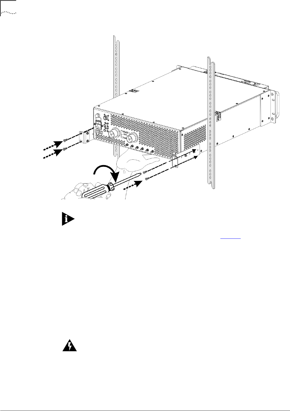
TheCompactMacroBTSismountedattherearoftherack,asshowninFigure6
andrequires3Urackspaces—approximately5.25in.(13.33cm)high,19in.
(48.26cm)wide,and24in.(60.96cm)deep.
34 Chapter2:InstallingtheCompactMacroBTS
StarSolutionsAll‐IPCDMA2000NetworkiCell PartNumberD02149A0
CompactMacroEV‐DOBTSInstallationandInitialConfigurationGuide October2008
Caution:
Figure6RearViewofInstallingtheCompactMacroBTS
Installationrequiresaccesstotherearoftheequipmentrack.
ToinstalltheCompactMacroBTSina19in.rack(SeeFigure6):
1Verifythatpowertothe19in.rackisstopped.
2VerifythattherackinwhichtheBTSisinstalledisearth‐grounded.
3VerifythatthemountingearshavebeensecuredtotheBTS.
4WhilesupportingtheundersideoftheBTSwithonehand,slidetheBTSintothe
rearoftherackuntilthefrontoftheBTSisflushwiththefrontoftherack.
5Usetwopairsoffasteners(screws)tosecuretheBTSmountingearstotherear
verticalrailsoftherack.
aInsertthetwobottomfasteners(screws).
bInsertthetwotopfasteners(screws).
Waituntilallinitialinstallationandconnectionproceduresinthischapterare
completebeforerestoringpowertotherack.
ConnectingtheCompactMacroBTSFrontPanelInterface 35
StarSolutionsAll‐IPCDMA2000NetworkiCell PartNumberD02149A0
CompactMacroEV‐DOBTSInstallationandInitialConfigurationGuide October2008
ConnectingtheCompact
MacroBTSFrontPanel
Interface
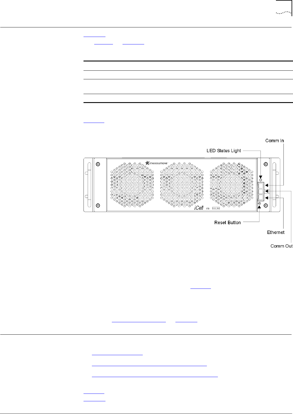
Table15describestheCompactMacroBTSfrontpanelinterfaceconnections.
SeeTable8onpage25forcablespecifications.
Figure7showsthefrontpanelinterfaceconnectionsfortheCompactMacroBTS.
Figure7CompactMacroBTSFrontPanel
ToconnecttheCompactMacroBTSfrontpanel:
1UsingaCAT‐5straightEthernetcablewithRJ‐45connectors,connectthe
EthernetportontheBTSfrontpanel(seeFigure7)toafreeportontheEthernet
switch.
2UsingastandardserialcablewithonemaleDB‐9connectorendandonefemale
DB‐9connectorend,connecttheCOMMINporttotheserialportofthetest
client(SeeTestClientHardwareonpage24).
ConnectingtheCompact
MacroBTSRearPanel
Interface
Thissectionincludes:
■ConnectingtheGPS
■ConnectingtheMainandDiversityAntennas
■ConnectingACPowertotheCompactMacroBTS
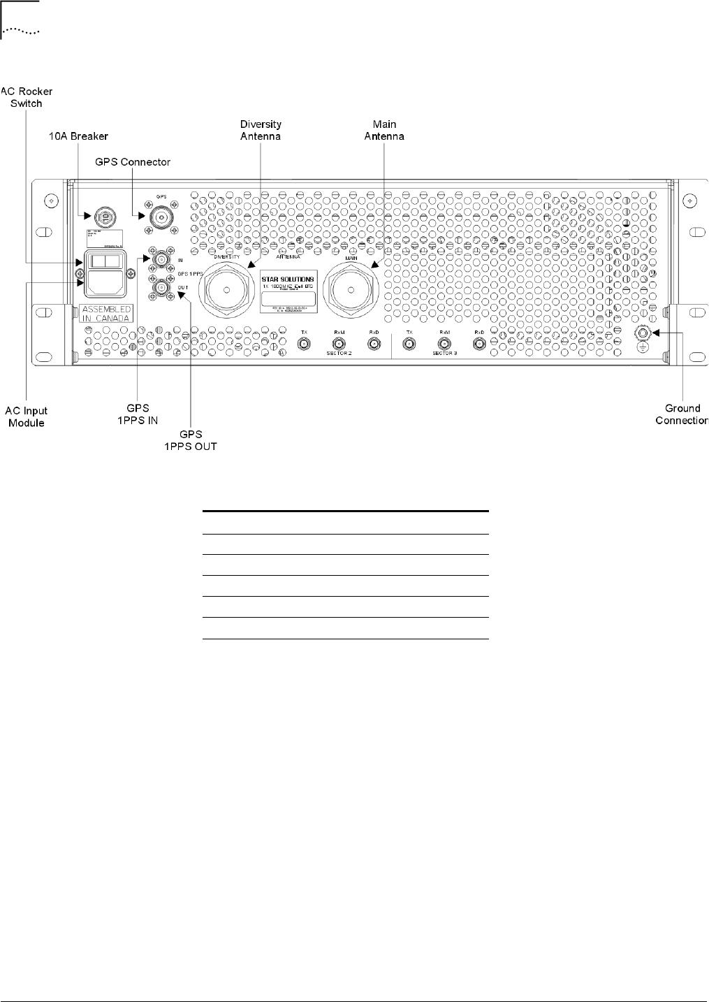
Figure8showstheCompactMacroBTSrearpanelwiringconnectors,while
Table16providesanexampleofthewiringparameters.
Table15CompactMacroBTSFrontPanelInterfaceConnections
Connection Description
ETHERNET ProvidesEthernetIPconnectiontoanRNC.
COMMIN UsedinconjunctionwithaPCtoconfiguretheIPaddressofthe
unit.
COMMOUT Attachedtoadditionalsectorsandshouldremaindisconnected.
36 Chapter2:InstallingtheCompactMacroBTS
StarSolutionsAll‐IPCDMA2000NetworkiCell PartNumberD02149A0
CompactMacroEV‐DOBTSInstallationandInitialConfigurationGuide October2008
Figure8CompactMacroBTSRearPanel
ConnectingtheGPSTheCompactMacroBTSrequiresaGPSantenna,andtheGPSsatellitesystemto
maintainprecisetiming.
GPSConnectionGuidelines
ABTSrequiresaccuratetiminginformationforbothToDandmessage
synchronization.
TheGPSisaconstellationof24active,andthreebackup,Earth‐orbitingsatellites.
AGPSreceivermustlocatefourormoreofthesesatellites,determinethe
distancetoeach,andusethisinformationtodeduceitsownlocation.This
operationisbasedontrilateration.
TheGPSreceiverandsatellitebothneedclocksthataresynchronizedtothe
nanosecond.EverysatellitecontainsanatomicclockandtheGPSreceiveritself
usesanordinaryquartzclock,whichitconstantlyresets.
Thereceiverlooksatincomingsignalsfromfourormoresatellitesandgaugesits
owninaccuracy—thereisonlyonevalueforthe"currenttime"thatthereceiver
Table16ExampleofBTSWiring
Name Type
PrimaryEthernet RJ45S
AntennaConnectors 7‐16DINFemale
1PPSINSMA
1PPSOUT SMA
PowerSupplySwitching ACPower

ConnectingtheCompactMacroBTSRearPanelInterface 37
StarSolutionsAll‐IPCDMA2000NetworkiCell PartNumberD02149A0
CompactMacroEV‐DOBTSInstallationandInitialConfigurationGuide October2008
Caution:
Caution:
Caution:
canuse.Thecorrecttimevaluewillcauseallofthesignalsthatthereceiveris
receivingtoalignatasinglepointinspace.Thattimevalueisthetimevalueheld
bytheatomicclocksinallofthesatellites.Sothereceiversetsitsclocktothat
timevalue,anditthenhasthesametimevaluethatalltheatomicclocksinallof
thesatelliteshave.
GPSReceiverProtection
TheCompactMacroBTSprovides+5VDCvoltageattheGPSantennainput
connectortopowertheexternalantenna.Verifythevoltageissufficientfor
normalantennaoperationandthepowerconsumptionoftheantennadoesnot
exceed275mW.
ConnectingaGPSCabletotheCompactMacroBTS
AGPSantennaconnectionpointisprovidedontherearpaneloftheCompact
MacroBTS(seeFigure8onpage36).
TheCompactMacroBTSconnectorsupportseitherNtypeorTMAtype
connectionsviathesuppliedN‐TMAadapter.
VerifyappropriatelightningprotectionisprovidedfortheGPSantennaand
cables.
AGPSantennaisanactiveantenna.Avoidashort‐circuitterminationoftheGPS
antennainputontheCompactMacroBTScase.Ifdifferentvoltageisfedtothe
externalGPSantenna,usetheDCblockmodulewithanexternal
lightning‐protectortoavoidback‐currentleakageintotheGPSantennainput.
ThenetworkoperatorisresponsibleforsupplyingtheGPSantennaandcables.
ToconnecttheexternalGPSantennacable:
1VerifythatexternalACpowertotheCompactMacroBTSisstopped.
Donotover‐tightenconnector.
2ConnecttheGPSantennacabletotheGPSconnectorontherearpanelofthe
CompactMacroBTS(seeFigure8onpage36).
1PPSConnections
The1PPSconnectorsaretype‐BNC.Terminationsaresuppliedwiththeunitand
shouldremaininstalledunlessasecondCompactMacroBTSisinstalled(second
FA).
■IfasecondcompactmacroBTSisinstalled,theunitconnectedtotheGPS
antennashouldsupply1PPStothesecondunit(1PPSoutto1PPSin).
38 Chapter2:InstallingtheCompactMacroBTS
StarSolutionsAll‐IPCDMA2000NetworkiCell PartNumberD02149A0
CompactMacroEV‐DOBTSInstallationandInitialConfigurationGuide October2008
Warning:
Caution:
Warning:
Warning:
Caution:
■If,forredundancyintheabovesituation,asecondGPSantennaisused,two
cablescanbeconnectedbetweentheboxes(1PPSoutto1PPSinx2).
Thenetworkoperatorisresponsibleforsupplyingthesecables.TheCompact
MacroBTSGPSportisafemaleN‐TypeconnectorandfemaleTNC‐Type.
ConnectingtheMainand
DiversityAntennas
Mainanddiversityantennaconnectionpointsareprovidedontherearpanelof
theCompactMacroBTS(seeFigure8onpage36).
BeforeConnectingRFCables
AllRFconnectorsthatarenotconnectedshouldbeterminated.Theshieldingof
allcoaxialconnectionsmustbegrounded.
ToavoidpossibledamagetoRFconnectors,donotexceed4in‐lbsoftorque.
ConnectingtheRFCables
Toconnectthemainanddiversityantennacables:
1VerifythatexternalACpowertotheCompactMacroBTSisstopped.
2VerifytheantennacablesarelabeledneartheCompactMacroBTSterminating
end.
Labelthecablesiftheyarenotalreadylabeled.
3Threadthe7‐16DIN‐typeconnector‐endoftheMAINcableontothe7‐16DIN
connector‐endontheantennaconnectionplate.
4Threadthe7‐16DIN‐typeconnector‐endoftheDIVERSITYcableontothe7‐16
DINconnector‐endontheantennaconnectionplate.
ConnectingACPowertothe
CompactMacroBTS
TheCompactMacroBTSrequiressufficientACpowertomeetoperating
requirements(forexample,thepowerconsumptionfor1F/3SwithsRNCis
approximately400watts).
SafetyAdvisory
PowerconnectionstotheCompactMacroBTSmustcomplywithlocalsafety
codes.
Powerconnectionsmustbeperformedbyqualifiedpersonnelonly.
Beforebeginning,verifythattheexternalACpowertotherackisdisconnected.

AddingSectors 39
StarSolutionsAll‐IPCDMA2000NetworkiCell PartNumberD02149A0
CompactMacroEV‐DOBTSInstallationandInitialConfigurationGuide October2008
Caution:
Caution:
ACPowerConnection
ToconnectACpowertotheCompactMacroBTS:
1VerifythattheexternalACpowertothe19in.rackisdisconnected.
2VerifythattherockerswitchonACinputmoduleisintheOFF(0)position(see
Figure8).
3ConnecttheACpowercordfromtheACinputmoduleontherearpanelofthe
CompactMacroBTStothe19in.rackpowersource.
Verifythatallinstallationandconnectionprocedureshavebeencompletedand
meetorexceedlocalstandardsbeforepoweringuptheCompactMacroBTS.
Verifyanantennaisconnectedbeforeapplyingpower.
4Restorepowertothe19in.rack.
5PoweruptheCompactMacroBTSbypressingtherockerswitchonACinput
moduletotheON(1)position.
TheCompactMacroBTSisreadyforinitialconfiguration.
AddingSectors Themainunitsupportstheadditionoftwomoresectorunits.Eachsectorunit
comesina2Uhigh,19in.wide,rack‐mountedchassis.
Thesector2andsector3connectorsaretypeQMA.Thesearesuppliedwith
terminationswhichmustremainattachedunlessadditionalsectorunitsare
beingused.
Ifadditionalsectorboxesarebeinginstalled,refertothewiringinstructions
suppliedwiththesectorexpansionboxesforinstallationprocedures.
MaintainingtheCompact
MacroBTS
TherearenouserserviceablepartsinsidetheCompactMacroBTScasing.The
BTSdoesprovideexternalfeaturesformonitoringandrestartingtheunit,if
required.
Thissectionincludes:
■FrontPanelLEDStatusLight
■ResetButton
■ReplacingtheFanModule
FrontPanelLEDStatusLight
AstatuslightonthefrontpaneloftheCompactMacroBTS(seeFigure7)
indicatesoveralloperationalstatus.
40 Chapter2:InstallingtheCompactMacroBTS
StarSolutionsAll‐IPCDMA2000NetworkiCell PartNumberD02149A0
CompactMacroEV‐DOBTSInstallationandInitialConfigurationGuide October2008
Caution:
Caution:
Table17describesthestatusinformationprovidedbythefrontpanelLEDstatus
light.
ResetButton
AresetbuttonislocatedonthefrontpaneloftheCompactMacroBTS(see
Figure7).Presstheresetbuttontoresettheunit.
Usetheresetbuttononlywhenallotherreconfigurationoptionshavefailed.
Pushingtheresetbuttontakestheunitoutofserviceungracefullyforseveral
minutes.
ReplacingtheFanModule
TheACinputpowertotheCompactMacroBTSchassismustbedisconnected,by
removingthepowercablefromtherearofthechassis,beforeremovingor
replacingthefanmodule.
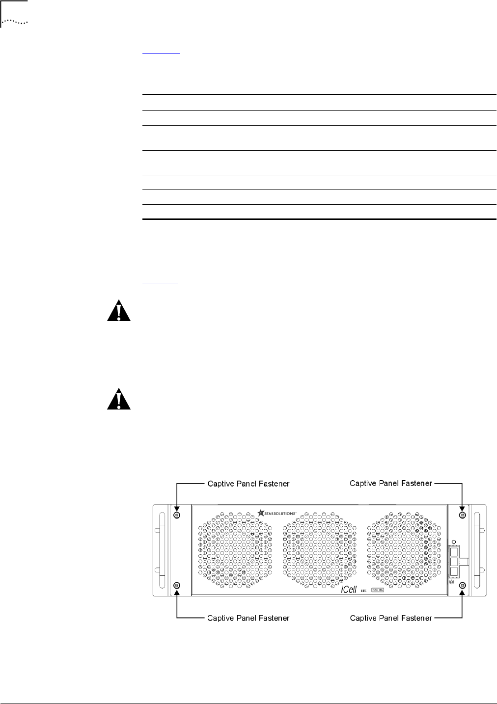
Figure9FanModule:CaptivePanelFastenerLocation
Toremovethefanmodule:
1Switchoffthepowerswitchlocatedonthebackplane.
Table17FrontPanelLEDStatusLight
Status Solid(TimingOK) Blinking(TimingNotOK) BTSOperational?
Normal Green BlinkingGreen Yes
Degrade
(MinorAlarms)
Orange BlinkingGreen Yes
SystemDisabled
(MajorAlarm)
Red BlinkingRed No
ACMJinBoot FlashingBlueandRed FlashingBlueandRed BTSisbootingup
UserDisabled Blue BlinkingBlue No
NoPower Off Off No

MaintainingtheCompactMacroBTS 41
StarSolutionsAll‐IPCDMA2000NetworkiCell PartNumberD02149A0
CompactMacroEV‐DOBTSInstallationandInitialConfigurationGuide October2008
2UnplugtheACpowercablelocatedonthebackplane.
3UsingaNo.2Phillipsscrewdriver,unfastenthefourcaptivepanel‐fasteners
locatedonthefrontfanpanel.
4Unplugthefanconnectors(followthewiresfromthefanstotheconnectors).
Toinstallthefanmodule:
1PlugthefanconnectorsintotheconnectorlocatedunderthePA.
2UsingaNo.2Phillipsscrewdriver,fastenthefourcaptivepanel‐fastenerslocated
onthefrontfanpanel.
3PlugtheACpowercableintothebackplane.
4Switchonthepowerswitchlocatedonthebackplane.

42 Chapter2:InstallingtheCompactMacroBTS
StarSolutionsAll‐IPCDMA2000NetworkiCell PartNumberD02149A0
CompactMacroEV‐DOBTSInstallationandInitialConfigurationGuide October2008

StarSolutionsAll‐IPCDMA2000NetworkiCell PartNumberD02149A0
CompactMacroEV‐DOBTSInstallationandInitialConfigurationGuide October2008
3CONFIGURINGTHECOMPACTMACROBTS
AboutThisChapter Thischapterincludes:
■InitialSetup
■ConfiguringtheBTSBAPIP
■ConfiguringtheBTS(s)
InitialSetup Thissectionincludes:
■ConfiguringaTestClient
■ConnectingtheTestClienttotheEthernetSwitch
■PerformingaPingTest
■ConfiguringtheIPSwitch
■UpdatingtheRNCSoftwareandConfiguration
■ModifyingtheRNCandBTSConfigurationFiles
WhentheCompactMacroBTSships,itscomponentnetworkelementsare
pre‐configuredwithnon‐routableIPaddresses.Thissectiondescribeshowto
changetoaddressesthatareroutableonyournetwork.
Table18liststhefactorydefaultIPconfigurationplan.
Table18FactoryDefaultIPConfigurationPlan
Device IPAddress Name
Gateway 10.10.10.1 DGW
EthernetSwitch 10.10.10.2 ES
RNC1 10.10.10.50 RNC1
RNC2 10.10.10.51 RNC2
RNCn(nmustbelessthan10) 10.10.10.(50+n‐1) RNCn
BMPBTS110.10.10.60 BMPBTS1
BMPBTS210.10.10.61 BMPBTS2
BMPBTSn(nmustbelessthan10)10.10.10.(60+n‐1) BMPBTSn
BAPBTS110.10.10.70 BAPBTS1
BAPBTS210.10.10.71 BAPBTS2
BAPBTSn(nmustbelessthan10)10.10.10.(70+n‐1) BAPBTSn
46 Chapter3:ConfiguringtheCompactMacroBTS
StarSolutionsAll‐IPCDMA2000NetworkiCell PartNumberD02149A0
CompactMacroEV‐DOBTSInstallationandInitialConfigurationGuide October2008
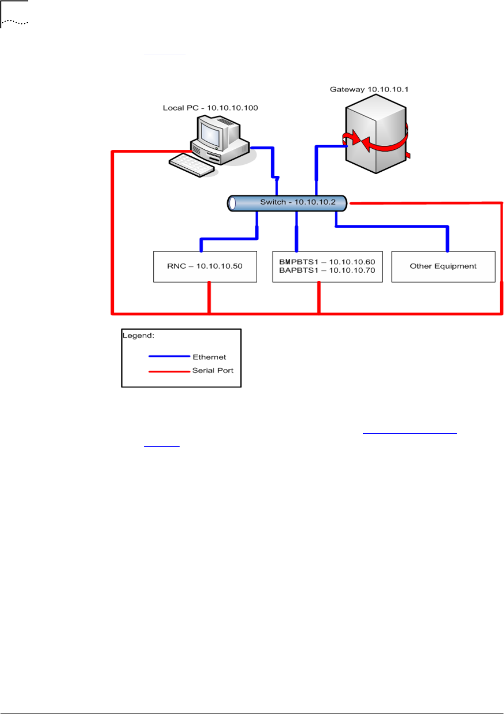
Figure10showstheBSSconnections.
Figure10ConnectionDiagram
ConfiguringaTestClientConfigureatestclientwithtwoIPaddresses(seeTestClientHardwareon
page24).ConfigureoneIPaddressontheshipping(10.10.10.xx)networkandthe
otheronyourlocalnetwork.
Toconfigureatestclient:
1InWindows,clicktheStartbutton.
2Right‐clickMyNetworkPlaces,thenclickProperties.
3Right‐clickLocalAreaConnection,thenclickProperties.
4IntheGeneraltab,double‐clickInternetProtocol(TCP/IP).
5IntheGeneraltab,clickUsethefollowingTCP/IPaddress.
aEnteranIPaddressthatisvalidonyournetwork.
bEnterthesubnetmaskforyournetwork.
cEnterthedefaultgatewayaddressforyoursubnet.
6ClickAdvanced.
aInIPaddresses,clickAdd.
bForIPaddress,enter10.10.10.100.

InitialSetup 47
StarSolutionsAll‐IPCDMA2000NetworkiCell PartNumberD02149A0
CompactMacroEV‐DOBTSInstallationandInitialConfigurationGuide October2008
cForSubnetmask,enter255.255.255.0.
dClickAdd.
eInDefaultgateways,clickAdd
fForGatewayaddress,enter10.10.10.1.
gClickAdd.
hClickOK,thenOK,thenOK.
Table19liststheserialbaudrates.
ConnectingtheTestClientto
theEthernetSwitch
ConnectanEthernetcablefromaportonthetestclienttoanemptyportonthe
Ethernetswitch.
PerformingaPingTestPingeachofthenetworkelementsontheshippingnetwork.
Toperformthepingtest:
1Fromthetestclient,clickStart|Run.
2Entercmd.PingtheEthernetswitchbyentering:
ping10.10.10.2
3PingtheRNCbyentering:
ping10.10.10.50
4PingBTS1byentering:
ping10.10.10.60
5PingBTS1byentering:
ping10.10.10.70
ConfiguringtheIPSwitchWhentheBTSships,itscomponentnetworkelementsarepre‐configuredwith
non‐routableIPaddresses.Thissectiondescribeshowtochangetheaddressesto
the10.10.10.xxnetwork.
ConfiguringtheLENOVOSwitch
ToconfiguretheLenovoEthernetswitchserialconnection:
1ConnectanEthernetportontheswitchtotheEthernetportonthetestclient.
2Connecttheserialportontheswitchtotheserialportonthetestclient.
Table19SerialBaudRates
Device BPS Bits/Character ParityBit StopBits
RNC 38400 8None 1
EthernetSwitch Lenovo: 38400
Cisco: 9600
8None 1
BTS1 115200 8None 1

48 Chapter3:ConfiguringtheCompactMacroBTS
StarSolutionsAll‐IPCDMA2000NetworkiCell PartNumberD02149A0
CompactMacroEV‐DOBTSInstallationandInitialConfigurationGuide October2008
3Openupaterminalsoftwareprogram(forexample,HyperTerminal).
4PressenterandwaitfortheSwitch>prompt
5Enterthefollowingcommandsaseachpromptisdisplayed:
Switch>en
password:******
ContactStarSolutionssupportengineeringforpasswordinformation.
Switch#password
Switch#******
Switch#******
Switch#ipaddress<ipaddress><netmask>
Switch#ipgateway<gatewayaddress>
Switch#save
Switch#showswitch
IpAddress:10.10.10.2
SubnetMask:255.255.255.0
DefaultGateway:10.10.10.1
MACAddress:00:09:ca:14:94:10
SpanningTree:Disable
IGMPSnooping:Disable
Switch#exit
Switch><Ctrl‐a,thenz,thenx>
root@acmServer:/home/acmuser#
6Repeatsteps1through6forthenextunit.
UpdatingtheRNCSoftware
andConfiguration
ThissectionliststheproceduresrequiredtoupdatetheRNCsoftwareandthe
RNCconfiguration.
ThefollowingprocedureassumesthattheRNCimageisinthetemporary
directorythatwascreatedinthepreviousprocedure.
ToupdatetheRNCsoftwareandtheRNCconfiguration:
1Verifybootstrapdserviceisstopped.Ifbootstrapdserviceisstillrunning,stopit
byentering:/etc/rc.d/init.d/bootstrapdstop
2Installandupgradethelatestbootstrapdrpm(x.y.zistheversion,latestis0.9.3as
ofMay2007)byentering:
cd/tmp
rpm‐ebootstrapd‐x.y.z‐1.x86_64

InitialSetup 49
StarSolutionsAll‐IPCDMA2000NetworkiCell PartNumberD02149A0
CompactMacroEV‐DOBTSInstallationandInitialConfigurationGuide October2008
(Removestheoldoneifitexists)
rpm‐ivhbootstrapd‐x.y.z‐1.x86_64.rpm
3Zerooutoldsoftwareandconfigurationpartitionsbyentering:
ddif=/dev/zeroof=/dev/sda2
ddif=/dev/zeroof=/dev/sda3
ddif=/dev/zeroof=/dev/sda5
ddif=/dev/zeroof=/dev/sda6
ddif=/dev/zeroof=/dev/sda7
ddif=/dev/zeroof=/dev/sda8
ddif=/dev/zeroof=/dev/sda9
Donotperformthecommandfor/dev/sda4,ortheOSwillhavetoreinstalled.
4CopytheRNCsoftwareimage“bsc.img”intotheprimaryandsecondary
softwarebanksbyentering:
cd/tmp
ddif=bsc.imgof=/dev/sda2
ddif=bsc.imgof=/dev/sda3
5FirstmodifyandmakesuretheRNCconfigurationfile“bsc.cfg”isupdatedwith
thecorrectinformationandtheIPaddressesforallrelatedsystemcomponents.
ThenupdatetheRNCconfigurationbycopyingthe“bsc.cfg”configurationfileto
thesoftwareconfigurationbanksbyentering:
catbsc.cfg>/dev/sda6
catbsc.cfg>/dev/sda7
catbsc.cfg>/dev/sda8
catbsc.cfg>/dev/sda9
6Updatetheglobalconfigurationfiletotheglobalconfigurationbankbyentering:
catbsc‐gc.txt>/dev/sda5
7IfthenewRNCsoftwareimage“bsc.img”requiresupgradingtosoftwarebank2
and3abovewithoutchangingtheconfigurationfile,itisnotnecessarytoupdate
theconfigurationsoftwarebanks5to9.
8Rebootthesystembyentering:
reboot
ModifyingtheRNCandBTS
ConfigurationFiles
BeforetheRNCandtheBTSsoftwareconfigurationbanksareupdatedwiththe
configurationfiles(bsc.cfgandbts.cfg),thesefilesneedtobemodifiedwiththe
followingfieldsupdatedtomatchthesystembeingsetup.Theseconfiguration
filescurrentlycontainfactorydefaultinformationsuchasIPaddressandgateway
information.Theymustbeupdated,beforethedatacanbewrittentotheRNC
andtheBTSsystemssoftwareconfigurationbanks6to9.
50 Chapter3:ConfiguringtheCompactMacroBTS
StarSolutionsAll‐IPCDMA2000NetworkiCell PartNumberD02149A0
CompactMacroEV‐DOBTSInstallationandInitialConfigurationGuide October2008
ModifyingtheRNCConfiguration
1UseanyUnix‐compatibleeditingtooltoedittheRNCconfigurationfile(bts.cfg).
EditingtheconfigfilewithMS‐DOSeditors,suchasMSNotepadcanchangethe
filetoMS‐DOSformatandcorruptthebootprocess.Theconfigurationfilemust
beinUNIXformat.
MakesuretoupdatealltheIPaddressinformationforthesystem.IncorrectIP
systemaddressinformationwillcauseremoteconnectionfailure.
2RefertoTable20forthecorrectvaluesforthebsc.cfgfile.Changevalues,as
required,usingthevaluesspecifiedinthe“SetTo”columnofTable21.
ModifyingtheBTSConfigurationFile
UseanyUnix‐compatibleeditingtooltoedittheBTSconfigurationfile(bts.cfg).
EditingtheconfigfilewithMS‐DOSeditors,suchasMSNotepadcanchangethe
filetoMS‐DOSformatandcorruptthebootprocess.Theconfigurationfilemust
beinUNIXformat.
Thebootprocesswillstopat:
InitializeRFMmodule:...Ok
InitializeTIMEmodule:...Ok
Componentsinitialized.
RefertoTable21onpage51forthecorrectvaluesforthebts.cfgfile.Change
values,asrequired,usingthevaluesspecifiedinthe“SetTo”columnofTable21.
Table20bsc.cfgConfiguration
Ro
wColumn Name Type Value SetTo:
UTDORA‐BSC‐MIB::btsCount Integer 1Totalno.ofBTSs
UTDORA‐BSC‐MIB::bscPrimaryLansIp Integer 10.10.10.50 BSCaddress
UTDORA‐BSC‐MIB::bscIp Integer 10.10.10.50 BSCaddress
UTDORA‐BSC‐HRPD‐MIB::uatiColorCode Integer 42
UTDORA‐BSC‐HRPD‐MIB::uatiSubnetMask Integer 104
UTDORA‐BSC‐HRPD‐MIB::uatiSubnet String 0x00000000000000000000000001000000
TheabovethreefieldsmustmatchtheBTSconfiguration
0Normal UTDORA‐A11‐MIB::pdsnSharedSecret String 0x00000000 “delimitedvalue,ex:
“telostech”
UTDORA‐A11‐MIB::pdsnCount Integer 1No.ofPDSNs
0Start UTDORA‐A12‐MIB::aaaSharedSecret String 0x00000000 “delimitedvalue,ex:
“telostech”
ConfiguringtheBTSBAPIP 51
StarSolutionsAll‐IPCDMA2000NetworkiCell PartNumberD02149A0
CompactMacroEV‐DOBTSInstallationandInitialConfigurationGuide October2008
TheabovethreefieldsmustmatchtheRNCconfiguration.
ConfiguringtheBTSBAPIP
ToconfiguretheBTSApplicationProcessor(BAP)IPfortheBTS,pleasecontact
StarSolutionssupportengineering.
ConfiguringtheBTS(s) First,setuptheserialconnectiontotheBTS.ThenconfiguretheIPsettingsusing
theBTScommandpromptandthehttpinterface.RepeatforeachadditionalBTS
intherack.
ConfiguringtheSerial
ConnectiontotheBTS
ToconfiguretheserialconnectiontotheBTS:
1ConnecttheserialcabletotheBTSModemProcessor(BMP)serialportonthe
BTS.
2Enter:ctrl‐x
3WhenPressanykey…displays,clickanykeytointerrupttheprocess.
4Enterctochangetheinformation.
SeeFigure11,onpage53,beforeproceedingwithstep5.
5Changethefollowingvalues:
bootdevice :mottsec
processornumber :0
hostname :boothost
filename :vxworksT22ppc8560_IDORA_BMP.st
inetonethernet(e) :10.10.10.60:fffffe00
inetonbackplane(b) :
Table21bts.cfgConfiguration
Row Column Name Type Value SetTo
0End UTDORA‐BTS‐MIB::sectorAdministrativeState Integer 0 1
0 Start UTDORA‐BTS‐MIB::bscAbisRowStatus Integer 3 1
0Normal UTDORA‐BTS‐MIB::bscAbisIp Integer 10.10.10.50 IPofthe
BSC
0End UTDORA‐BTS‐MIB::bscAbisAdministrativeState Integer 0 1
0 Start UTDORA‐BTS‐CSM6800‐MIB::sectorValid Integer 3 1
0End UTDORA‐BTS‐HRPD‐MIB::sectorValid Integer 3 1
UTDORA‐BTS‐HRPD‐MIB::uatiColorCode Integer 42
UTDORA‐BTS‐HRPD‐MIB::uatiSubnet String 0x00000000000000000000000001000000
UTDORA‐BTS‐HRPD‐MIB::subnetMask Integer 104

52 Chapter3:ConfiguringtheCompactMacroBTS
StarSolutionsAll‐IPCDMA2000NetworkiCell PartNumberD02149A0
CompactMacroEV‐DOBTSInstallationandInitialConfigurationGuide October2008
hostinet(h) :10.10.10.70
gatewayinet(g) :10.10.10.1
user(u) :target
ftppassword(pw)(blank=usersh) :target
flags(f) :0x0
targetname(tn) :bts1
startupscript(s) :bmptest.txt
other(o) :
Theflashmustbeupdatedbyenteringw,beforeproceedingtoenter@.
6Verifythefollowingconditionsexist:
■StartingRFsector1...OK.
■StartingRFsector2...OK.
■StartingRFsector3...OK.
7NotetheMACAddressforfutureuse.
8Verifythattheunitresets.

ConfiguringtheBTS(s) 53
StarSolutionsAll‐IPCDMA2000NetworkiCell PartNumberD02149A0
CompactMacroEV‐DOBTSInstallationandInitialConfigurationGuide October2008
Figure11ExampleofTheChangeCommand
BootLinefrom/fd0/BOOTCFG.TXT:
<mottsec(0,0)boothost:vxworksT22ppc8560_IDORA_BM
P.ste=172.25.136.168:fffffe00h=172.25.136.169g=172.25.136.1
u=targetpw=targe
ttn=bmps=bmptest.txt>
Pressanykeytostopauto‐boot...
a7
[VxWorksBoot]:c
'.'=clearfield;'‐'=gotopreviousfield;^D=quit
bootdevice:mottsec0<Enter>
processornumber:0<Enter>
hostname:boothost<Enter>
filename:vxworksT22ppc8560_IDORA_BMP.st<Enter>
inetonethernet(e):172.25.136.168:fffffe00<Enter>
inetonbackplane(b):<Enter>
hostinet(h):172.25.136.169<Enter>
gatewayinet(g):172.25.136.1<Enter>
user(u):target<Enter>
ftppassword(pw)(blank=usersh):target<Enter>
flags(f):0x0<Enter>
targetname(tn):bmp<Enter>
startupscript(s):bmptest.txt<Enter>
other(o):<Enter>
[VxWorks Boot]:w <Enter>
[VxWorks Boot]:@ <Enter>
->

54 Chapter3:ConfiguringtheCompactMacroBTS
StarSolutionsAll‐IPCDMA2000NetworkiCell PartNumberD02149A0
CompactMacroEV‐DOBTSInstallationandInitialConfigurationGuide October2008

StarSolutionsAll‐IPCDMA2000NetworkiCell PartNumberD02149A0
CompactMacroEV‐DOBTSInstallationandInitialConfigurationGuide October2008
AREGULATORYNOTICES
Caution:
U.S.RegulatoryStatement ThisdevicecomplieswithPart15oftheFCCRules.Operationofthisdeviceis
subjecttothefollowingtwoconditions:(1)thisdevicemaynotcauseharmful
interference,and(2)thisdevicemustacceptanyinterferencereceivedincluding
interferencethatmaycauseundesiredoperation.
ThisequipmenthasbeentestedandfoundtocomplywiththelimitsforaClassA
digitaldevice,pursuanttopart15oftheFCCRules.Theselimitsaredesignedto
providereasonableprotectionagainstharmfulinterferencewhentheequipment
isoperatedinacommercialenvironment.Thisequipmentgenerates,uses,and
canradiateradiofrequencyenergyand,ifnotinstalledandusedinaccordance
withtheinstructionmanual,maycauseharmfulinterferencetoradio
communications.Operationofthisequipmentinaresidentialareaislikelyto
causeharmfulinterferenceinwhichcasetheuserwillberequiredtocorrectthe
interferenceathisownexpense.
CanadianRegulatory
Statement
ThisClassAdigitalapparatuscomplieswithCanadianICES‐003.
CetappareilnumériquedelaclasseAestconformeàlanormeNMB‐003du
Canada.
UnauthorizedmodificationsorchangesnotexpresslyapprovedbyGlobalStar
SolutionsULCcouldvoidcompliancewithregulatoryrules,andtherebyyour
authoritytousethisequipment.
RFExposureMPEExhibit Thisdeviceoperatesatfrequenciesinthe1900MHzregion.Maximum
permissibleexposureinthisregionisspecifiedunderperFCCPart1,Section
1.1310,Table1,as1mW/cm2.
FCCPart1,Section1.1307statesthatPart24E(BroadbandPCS)devicesare
excludedfromroutineenvironmentalevaluationwhenoperatingatpowerlevels
beneathamaximumEIRPof3280W.
EIRP(EffectiveIsotropicRadiatedPower)istheamountofpowerthata
theoreticalisotropicantenna(thatevenlydistributespowerinalldirections)
wouldemittoproducethepeakpowerdensityobservedinthedirectionof
maximumantennagain.
EIRPcantakeintoaccountthelossesintransmissionlineandconnectorsand
includesthegainoftheantenna.

58 AppendixA:RegulatoryNotices
StarSolutionsAll‐IPCDMA2000NetworkiCell PartNumberD02149A0
CompactMacroEV‐DOBTSInstallationandInitialConfigurationGuide October2008
EIRP=Pt‐Lc+Ga
WhereEIRPandPt(poweroftransmitter)areindBm,cablelosses(Lc)isindB,
andantennagain(Ga)isexpressedindBi,relativetoa(theoretical)isotropic
referenceantenna.
Noantennaissuppliedwiththisunit.Therefore,basedonmeasuredRFoutput
powerof26.18wattsat1947.5MHzandassumptionofcablelossiszero,the
maximumantennagainthatwillallowtheEIRPtoremainunderthe
environmentalevaluationexclusionlimitof3280wattsis20.97dB.
MPEisdeterminedbythefollowingrelationship:
PowerDensityPd(mW/cm2)=EIRP/4 d2
Whered=distance.
3280watts=3.28x10⁶mW
Therefore:
d = (EIRP/4 Pd)1/2
= (3.28x10⁶ mW/ 4 1 mW/cm2)) 1/2
=510.89=511cm
Theminimumsafedistancefromaradiatingstructureexhibitingamaximumgain
of20.97dBconnectedtotheCompactMacroBTS,wheninstalledand
transmittingatfulloutputpower,is511cm.

StarSolutionsAll‐IPCDMA2000NetworkiCell PartNumberD02149A0
CompactMacroEV‐DOBTSInstallationandInitialConfigurationGuide October2008
BACRONYMSANDABBREVIATIONS
Thisappendixdefinesacronymsandabbreviationsthatmaybeusedinthis
guide.
Table22ListofAcronyms
Acronym Definition
1PPS 1PulsePerSecond
AC AlternatingCurrent
ANSI AmericanNationalStandardsInstitute
AWG AmericanWireGauge
BAP BTSApplicationProcessor
BMP BTSModemProcessor
BSS BaseStationSubsystem
BTS BaseTransceiverStation
CAT‐5Category5Cable
CDMA CodeDivisionMultipleAccess
DB‐9Standardserialcableconnector
DC DirectCurrent
DIN DeutschesInstitutfürNormung
EIRP EffectiveIsotopicRadiatedPower
ESD ElectrostaticDischarge
EV‐DO Evolution‐DataOptimized
FA FrequencyAllocation
FCC FederalCommunicationsCommission
GHz Gigahertz
GND Ground
GPS GlobalPositioningSystem
HA HomeAgent
HLR HomeLocationRegister
IGMP InternetGroupManagementProtocol
IP InternetProtocol
LAN LocalAreaNetwork
MAC MediaAccessControl
MIB ManagementInformationBase
MSC MobileSwitchingCenter
PC PersonalComputer
PCM PulseCodeModulation
PDSN PacketDataServingNode

60 AppendixB:AcronymsandAbbreviations
StarSolutionsAll‐IPCDMA2000NetworkiCell PartNumberD02149A0
CompactMacroEV‐DOBTSInstallationandInitialConfigurationGuide October2008
PSTN PublicSwitchedTelephoneNetwork
RF RadioFrequency
RJ‐45 RegisteredJack‐45
RNC RadioNetworkController
RS232 RecommendedStandard232
QMA QuickdisconnectversionoftheSMAconnector
SMA SubMiniatureversionA[connector]
SSH SecureShell
TCP TransmissionControlProtocol
TDM TimeDivisionMultiplexed
ToD TimeofDay
USB UniversalSerialBus
VAC Volts,AlternatingCurrent
VDC Volts,DirectCurrent
Table22ListofAcronyms(continued)
Acronym Definition

GlobalStarSolutionsULC
120‐4600JacombsRoad
Richmond,BritishColumbiaV6V3B1Canada
www.starsolutions.com
Copyright©2008GlobalStarSolutionsULC
PartNumberD02149A0


