Starix Technology RWPC06 UltraWideband PC Card Adapter User Manual Wionics NECCardbusDemoBoardUser sGuide
Realtek Semiconductor Corp. - Wionics Research UltraWideband PC Card Adapter Wionics NECCardbusDemoBoardUser sGuide
RWPC06 users guide
Wionics Research, Realtek Group, Irvine, CA
1
All Rights Reserved by Wionics Research
Wionics/NEC Cardbus Demo Board
User’s Guide
Revision A
Wionics Research
RealTEK Group
Wionics Research, Realtek Group, Irvine, CA
2
All Rights Reserved by Wionics Research
Table of Contents
1. Introduction.............................................................................................................3
2. System Description..................................................................................................3
2.1. UWB PHY...................................................................................................4
2.2. FPGA S200..................................................................................................4
2.3. NEC MAC...................................................................................................4
2.4. EEPROM.....................................................................................................4
Wionics Research, Realtek Group, Irvine, CA
3
All Rights Reserved by Wionics Research
1 Introduction
This document describes the operations, interfaces, schematic and layout of the
Wionics/NEC Cardbus Demo Board.
This equipment may only be operated indoors. Operation outdoors is in violation 47 USC
301 and could subject the user to serious legal penalties
This device complies with 47 CFR Part 15 of the FCC rules. Operation is subject to 1)
this device may not cause harmful interference and 2) this device must accept any
interference received, including interference that may cause undesired operation
2 System Description
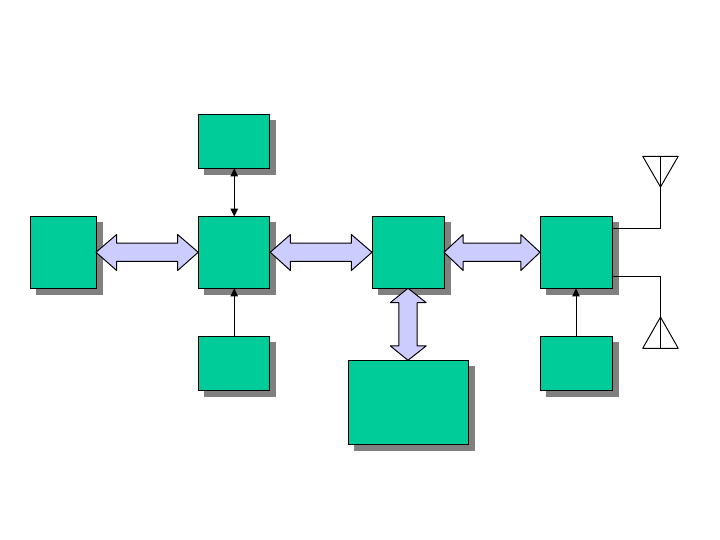
Figure 1 shows the system block diagram of the Wionics/NEC Cardbus Demo Board.
UWB
PHY
UWB
PHY
FPGA
S200
FPGA
S200
NEC
MAC
NEC
MAC
ANT2
ANT1
MPI_PHYMPI_MAC
PHY Debugging
&
FPGA JTAG
Interface
PHY Debugging
&
FPGA JTAG
Interface
Cardbus
Interface
Cardbus
Interface
512K
EEPROM
512K
EEPROM
MPI_DBG
30MHz
Xtal
30MHz
Xtal 66MHz
OSC
66MHz
OSC
Figure 1 System Block Diagram
The demo system mainly consists of three main chips – (i) UWB PHY, (ii) FPGA S200
and (iii) NEC MAC. Up to two antennas can be supported by the UWB PHY for
performance improvement. The existence of FPGA S200 is not necessary for a real
product. It serves the purpose of PHY development. The FPGA bridges all the mac-phy
interface signals between the NEC MAC and UWB PHY. For the users of the demo
board, the FPGA and the PHY debugging interface are transparent in nature. A serial
EEPROM is required to store proper data/commands for the PHY chip and MAC chip.
To make the system work properly, the EEPROM should be loaded with proper content
Wionics Research, Realtek Group, Irvine, CA
4
All Rights Reserved by Wionics Research
by using the EEPROM utility provided by NEC. Two basic clock frequencies are used in
the system – 30MHz for MAC and 66MHz for PHY. Some more details of the
components are shown in the following sections.
2.1 UWB PHY
This chip integrates the RF and baseband functions of a UWB PHY defined by the
standard organization. This version of PHY chip is packaged in 64 QFN form factor. The
analog/RF section requires 1.8V and 3.3V to operate. The digital core operates with 1.5V
and the I/O voltage can support a range of 1.8V~3.3V.
2.2 FPGA S200
This is an FPGA chip from Xilinx (XC3S200). When PHY debugging is needed,
debugging code will be loaded to the FPGA to bypass the MPI signals to the PHY
debugging interface. The problems between MAC and PHY can be isolated during
development. In normal operating mode with normal FPGA code loaded, the FPGA is
simply transparent to the demo board users. In short, the users do not need to care about
detail with the FPGA. Three voltages are required by this chip in the system – 1.2V, 2.5V,
3.3V and VIO (1.8V in this system).
2.3 NEC MAC
This MAC chip is from NEC which has a standard MPI interface to communicate with a
standard UWB PHY, as well as a standard cardbus/PCI interface to connect directly to a
PC. This chip requires a clean analog voltage of 1.5V. Other digital voltages are 1.5V and
3.3V.
2.4 EEPROM
This chip is a serial EEPROM from Atmel with a capacity of 512Kb. It is used by the
MAC to store the initialization data and command sequence required by the MAC and
PHY on start up. This chip requires 3.3V only.
shows the PCB stackup and some layer usage information.
3 Software Install
• First you should copy the NEC control software (example:
UPD720170Utilities_060302.zip) and unzip to a convenient directory.
• Plug the PCCard Demo board into the PC.
• Found new hardware wizard will automatically start.
• When prompted, point the wizard to the Driver sub-directory that you just
unzipped.
Wionics Research, Realtek Group, Irvine, CA
5
All Rights Reserved by Wionics Research
• This should happed a second time.
• Now the device will be ready for operation.
4 Software Operation
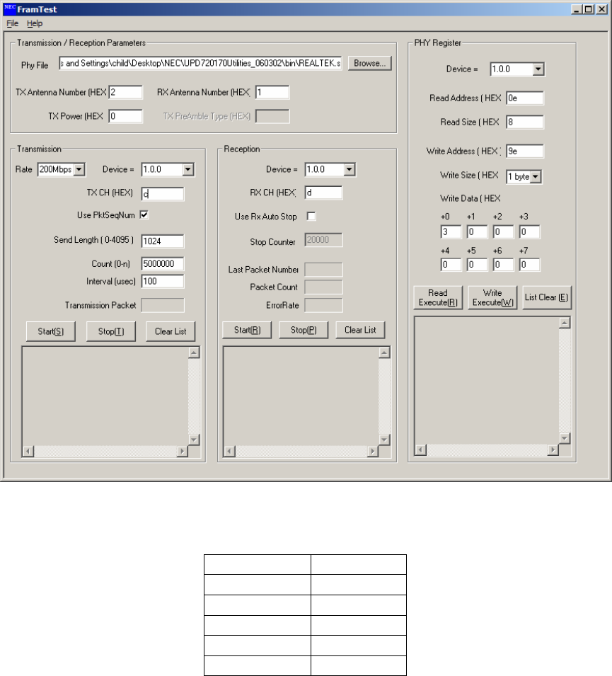
The executable is named FramTest.exe in the bin sub-directory. The application will let
you select transmit and receive. For transmit you may select parameters such as channel,
data rate and packet length. For spectrum measurements be sure to set a long packet
length (longest packet is 4095) and a short packet interval (shortest is 5 usec). A screen
shot of the application is in Figure 2. Table 1 shows the correspondence between the
application channel selection and the MBOA channel definitions.
Figure 2. FramTest application screen shot.
Table 1. Channel Selection Table
TFC Channel
HEX Value
1 9
2 A
3 B
4 C
5 D
Wionics Research, Realtek Group, Irvine, CA
6
All Rights Reserved by Wionics Research
6 E
7 F