Statsignal Systems WTR171 Water Meter Interface, Model WTR171 User Manual WTR171 Instruction Manual
Statsignal Systems Inc Water Meter Interface, Model WTR171 WTR171 Instruction Manual
Users Manual

© Copyright 2002, StatSIGNAL Systems, Inc.
All Rights Reserved
* * C O N F I D E N T A L * *
PN# 100171-03
Water Meter Interface
Final Assembly Procedures
Document # 8000171-60-01
March 11, 2003
Confidential Document
This is a confidential document which is owned and Copyrighted by StatSIGNAL
Systems, Inc., which reserves all its rights. This document may be reproduced
only with the express written permission of StatSIGNAL Systems, Inc.

Final Assembly Procedures
100171-03 Water Meter Interface Document 8000171-60-01
March 11, 2003 Page i
© Copyright 2003, StatSignal Systems, Inc.
All Rights Reserved
* * C O N F I D E N T A L * *
SIGN OFF PAGE
Engineering Manager: Executive Vice President:
Print Name: Print Name:
Signature: Signature:
Date: Date:
Production Manager:
Print Name:
Signature:
Date:

Final Assembly Procedures
100171-03 Water Meter Interface Document 8000171-60-01
March 11, 2003 Page ii
© Copyright 2003, StatSignal Systems, Inc.
All Rights Reserved
* * C O N F I D E N T A L * *
Revision History
Date Revision Description Author
11/15/02 00 First Draft J. Davis, E. Ocheseanu, H.
Westergren
11/20/02 00 2nd Draft H. Westergren, J. Davis
11/25/02 00 3rd Draft J. Davis, E. Ocheseanu, H.
Westergren
03/11/03 01 Changed Base Assembly I & II procedure;
Released for Production
H. Westergreen
E. Ocheseanu
Final Assembly Procedures
100171-03 Water Meter Interface Document 8000171-60-01
March 11, 2003 Page iii
© Copyright 2003, StatSignal Systems, Inc.
All Rights Reserved
* * C O N F I D E N T A L * *
Table of Contents
1. SCOPE................................................................................................................................................................1
2. REFERENCES ....................................................................................................................................................1
3. SAFETY PRECAUTIONS..................................................................................................................................1
4. MATERIALS AND TOOLS REQUIRED...........................................................................................................1
4.1 MATERIALS ................................................................................................................................................1
4.2 TOOLS........................................................................................................................................................2
5. PROCEDURES ....................................................................................................................................................2
5.1 PREPARATION ............................................................................................................................................2
5.2 22 AWG 3.5” RED/BLACK WIRE ASSEMBLY (222051).......................................................................2
5.3 22/3 AWG 3FT WIRE ASSEMBLY (222056) ..........................................................................................2
5.4 BATTERY ASSEMBLY (171500) ..................................................................................................................2
5.5 LID ASSEMBLY (171501)..........................................................................................................................2
5.6 BASE ASSEMBLY-I (171502)...................................................................................................................3
5.7 BASE ASSEMBLY-II (171503) ................................................................................................................3
5.8 FINAL ASSEMBLY (100171-XXX)..............................................................................................................3
100171-03 Water Meter Interface
Final Assembly Procedures 8000171-60-01
March 11, 2003 Page 1
© Copyright 2003, StatSignal Systems, Inc.
All Rights Reserved
* * C O N F I D E N T A L * *
1. SCOPE
This document provides the procedures required to safely and
efficiently install the 200171-xx Water Meter Circuit Board
Assembly with a 171404-xx battery assembly into the 171400-
xx enclosure to produce the 100171-xx finished good Water
Meter used by StatSIGNAL Systems, Inc.
2. REFERENCES
3. FCC STATEMENT
This equipment has been tested and found to comply with the
limits for a Class A digital device, pursuant to part 15 of
the FCC Rules. These limits are designed to provide
reasonable protection against harmful interference when the
equipment is operated in a commercial environment. This
equipment generates, uses, and can radiated radio frequency
energy and, if not installed and used in accordance with the
instruction manual, may cause harmful interference to radio
communications. Operation of this equipment in a
residential area is likely to cause harmful interference in
which case the user will be required to correct the
interference at his own expense.
4. MATERIALS AND TOOLS REQUIRED
4.1 Materials
The following materials are required to enable
completion of the installation process:
a. 1 each Water Meter Circuit Board Assembly
(200171-xx)
b. 1 each Water Meter Lid (171501)
c. 1 each Water Meter Base (171502)
d. 1 each Battery Assembly (171500)
e. 1 each 3V BR-AG Lithium battery (362001)
f. 2 each 1” Double Stick Tape (777005)
g. 1 each 1.5-5.0 mm PG7 Cord Grip (222059)
h. 1 each O-RING Gasket (777000)
i. 4 each 4/40 x ¼ Pan Head Phillips Screws (777001)
j. 1 each 22 AWG 3.5” long red/black wire asby.
100171-03 Water Meter Interface
Final Assembly Procedures 8000171-60-01
March 11, 2003 Page 2
© Copyright 2003, StatSignal Systems, Inc.
All Rights Reserved
* * C O N F I D E N T A L * *
(222051)
k. 1 each 3ft. long 22/3-AWG wire asby. (222056)
l. 1 each paper tie (999110)
4.2 Tools
The following tools are required to enable completion
of the installation process:
a) 1 Phillips Head screwdriver
b) Wire Strippers/cutter
c) 1 Drill with a 1/2” bit
5. PROCEDURES
5.1 Preparation
Prior to beginning the following procedures, the
operator must make sure he/she is grounded to avoid
electrostatic discharge.
5.2 22 AWG 3.5” Red/Black Wire Assembly (222051)
1) Assemble a Molex connector (222058) with one 3.5”
Red 22 AWG wire and one 3.5” Black 22 AWG wire to
complete the 222051 wire assembly
5.3 22/3 AWG 3ft Wire Assembly (222056)
1) Assemble a Molex connector (222058) with one 3 ft
22/3 AWG wire.
2) On the opposite side from the Molex connector
(222058) strip 1.5” of the outer jacket,
a. Strip 1/8” of the red and black inner wires,
b. Cut the green inner wire.
5.4 Battery Assembly (171500)
1) Solder the 22 AWG 3.5” long red wire of the 222051
wire assembly to the positive side of the battery
(362001)
2) Solder the 22 AWG 3.5” long black wire of the
222051 wire assembly to the negative side of the
battery (362001)
5.5 Lid Assembly (171501)

100171-03 Water Meter Interface
Final Assembly Procedures 8000171-60-01
March 11, 2003 Page 3
© Copyright 2003, StatSignal Systems, Inc.
All Rights Reserved
* * C O N F I D E N T A L * *
1) Drill a ½” hole in the center of lid (171401).
2) Insert the 22/3 AWG Wire Assembly (222056) through
the ½” Hole in the lid (171401) leaving 3ft of
Wire Assembly (222056) with the connector on the
inside of the Lid (171401) – see figure 2.
3) Secure Wire Assembly (222056) to the Lid (171401)
with the 1.5-5.0 mm PG7 Cord Grip (222059) -
leaving 3” of the wire (connector end) inside the
171501 Lid Assembly.
4) Coil the wire and secure with a paper tie
(999110).
5.6 Base Assembly-I (171502)
1) Apply 1” strip of Double Stick Tape (777005) on
the bottom of the 171402 enclosure, along the
edge, with one of the screw posts at the center
(for reference).
2) Strip the protective paper from the Double Stick
Tape (777005) and press the Battery Assembly
(171500) onto the Double Stick (777005), as close
to the edge of the 171402 base enclosure as
possible, keeping the screw post as a center point
of reference and the battery leads facing the
center of the 171402 enclosure with the positive
side on the right.
5.7 Base Assembly-II (171503)
1) Apply 1” Strip of Double Stick Tape (777005) in
the middle of the 171402 base enclosures parallel
with the Battery Assembly (171500).
2) Strip the protective paper from the Double Stick
Tape (777005) and press the 200171 Circuit Board
Assembly onto the tape making sure that the top
two corners of the 200171 Circuit Board Assembly
are pressed against the edge of the 171402
enclosure.
*** NOTE***
Before proceeding to the next step, make sure the 200171
Circuit Board Assembly is securely in place.
5.8 Final Assembly (100171-xxx)
1) Insert the O-RING Gasket (777000) into the lid
channel.
2) Connect the 3ft 22/3 AWG wire assembly (222056) to

100171-03 Water Meter Interface
Final Assembly Procedures 8000171-60-01
March 11, 2003 Page 4
© Copyright 2003, StatSignal Systems, Inc.
All Rights Reserved
* * C O N F I D E N T A L * *
the Pulse input of the 200171 Circuit Board
Assembly.
3) Connect the battery leads to the 2/pin header at
reference point BATT of the 200171 Circuit Board
Assembly.
4) Check the O-RING Gasket (777000) for seal.
5) Push the 22/3 AWG wire assembly (222056) away from
the Circuit Board Assembly (200171) and over the
battery assembly (171404) and carefully place the
Lid Assembly (171501) on the Base Assembly
(171503).
*** NOTE***
Before proceeding to the next step, make sure the O-Ring
Gasket is properly installed to ensure the seal.
6) Using the Phillips Head Screwdriver and the 4
screws secure the Lid Assembly (171501) tightly to
the Base Assembly (171503).
Final Assembly Procedures Document 8000171-60-00
100171-xx Water Meter Interface Appendix
November 25, 2002 Page 5
© Copyright 2003, StatSignal Systems, Inc.
All Rights Reserved
* * C O N F I D E N T A L * *
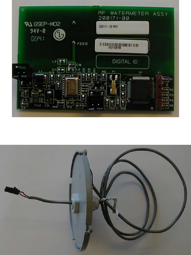
Figure 1 – 200171-xx Circuit Board Assembly
Figure 2 – 171501 Lid Assembly
Final Assembly Procedures Document 8000171-60-00
100171-xx Water Meter Interface Appendix
November 25, 2002 Page 6
© Copyright 2003, StatSignal Systems, Inc.
All Rights Reserved
* * C O N F I D E N T A L * *
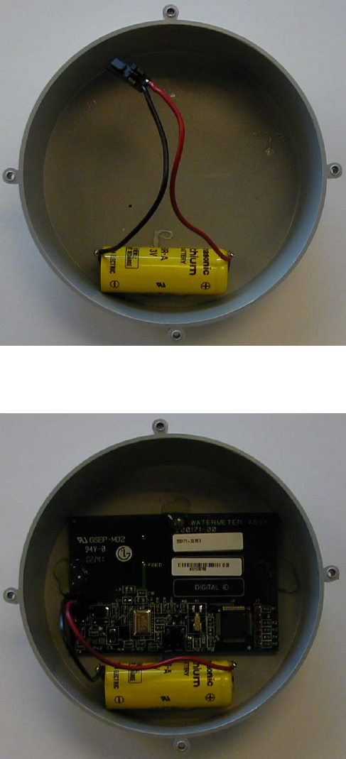
Figure 3 – 171502 Base Assembly I
Figure 4 – 171502 Base Assembly II