Steinberg HALion Sonic 3 – Operation Manual Instruction OM En
User Manual: Steinberg HALion Sonic 3 - Instruction Manual Free User Guide for Steinberg HALion Software, Manual
Open the PDF directly: View PDF ![]() .
.
Page Count: 276 [warning: Documents this large are best viewed by clicking the View PDF Link!]
- Table of Contents
- Installation and Setup
- Introduction
- Common Editing Methods
- Global Functions and Settings
- Plug-in Functions Section
- Plug-in Name and Steinberg Logo
- Toolbar
- Performance Controls
- Quick Controls
- Value Tooltips
- Accessing Quick Controls
- Assigning Quick Controls
- Unassigning Quick Controls
- Quick Control Assignments Editor
- Managing Quick Controls
- Adjusting the Curvature
- Setting the Mode for the Quick Control Assignment
- Neutral Setting
- Bypassing Quick Controls
- Assigning Quick Controls in the Modulation Matrix
- Trigger Pads
- Options Page
- Editing Programs
- Editing Layers
- FlexPhraser
- Managing Your Sounds
- Automation
- MIDI Editing and Controllers
- Mixing and Effect Handling
- Included Instruments
- Effects Reference
- Note Expression
- Library Manager
- Using the Standalone Version of the Plug-In
- Index

Operation Manual
Matthias Klag, Michael Ruf
Cristina Bachmann, Heiko Bischoff, Christina Kaboth, Insa Mingers, Matthias Obrecht, Sabine Pfeifer,
Benjamin Schütte, Marita Sladek
This PDF provides improved access for vision-impaired users. Please note that due to the complexity and
number of images in this document, it is not possible to include text descriptions of images.
The information in this document is subject to change without notice and does not represent a commitment
on the part of Steinberg Media Technologies GmbH. The software described by this document is subject to
a License Agreement and may not be copied to other media except as specifically allowed in the License
Agreement. No part of this publication may be copied, reproduced, or otherwise transmitted or recorded, for
any purpose, without prior written permission by Steinberg Media Technologies GmbH. Registered licensees
of the product described herein may print one copy of this document for their personal use.
All product and company names are ™ or ® trademarks of their respective owners. For more information,
please visit www.steinberg.net/trademarks.
© Steinberg Media Technologies GmbH, 2017.
All rights reserved.

Table of Contents
3
5Installation and Setup
5Conventions
6System Requirements
7Downloading Program Files
7Installing the Program
7Activating Your License
8Registering Your Software
8How You Can Reach Us
8About the Documentation
8Setting Up
10 Introduction
10 Window Overview
12 Common Editing Methods
12 Dials and Sliders
12 Buttons
12 Value Fields
13 Using Key Commands
13 Presets
15 Global Functions and Settings
15 Plug-in Functions Section
17 Plug-in Name and Steinberg Logo
17 Toolbar
17 Performance Controls
18 Quick Controls
24 Trigger Pads
26 Options Page
32 Editing Programs
32 Program Page Parameters
36 Editing Layers
36 Voice Tab
40 Pitch Tab
40 Oscillator Tab
43 Filter Tab
46 Amplifier Tab
48 Envelopes
54 LFOs
58 Using the Keymap
58 AUX Tab
59 Expression Controls for Instrument Layers
61 Insert Effects
62 Step Modulator
64 Modulation Matrix
76 FlexPhraser
77 Loading Phrases
77 FlexPhraser Parameters
81 Recording the MIDI Output of the
FlexPhraser
81 Phrase Playback Types
82 Variations
82 User Phrases
88 Managing Your Sounds
88 About Programs, Layers, Multis, Macro
Pages, and Presets
89 Loading Programs
90 Load Dialog
90 Slot Rack
92 Managing and Loading Files
100 Automation
100 Automation Page
100 Setting Up Automation
102 MIDI Editing and Controllers
102 MIDI Page
103 MIDI Controllers
106 Mixing and Effect Handling
106 Mix Page
107 Effect Handling
109 Included Instruments
109 Auron
117 Trium
125 Voltage
131 Model C
137 HALiotron
139 B-Box
145 World Instruments
149 World Percussion
153 Anima
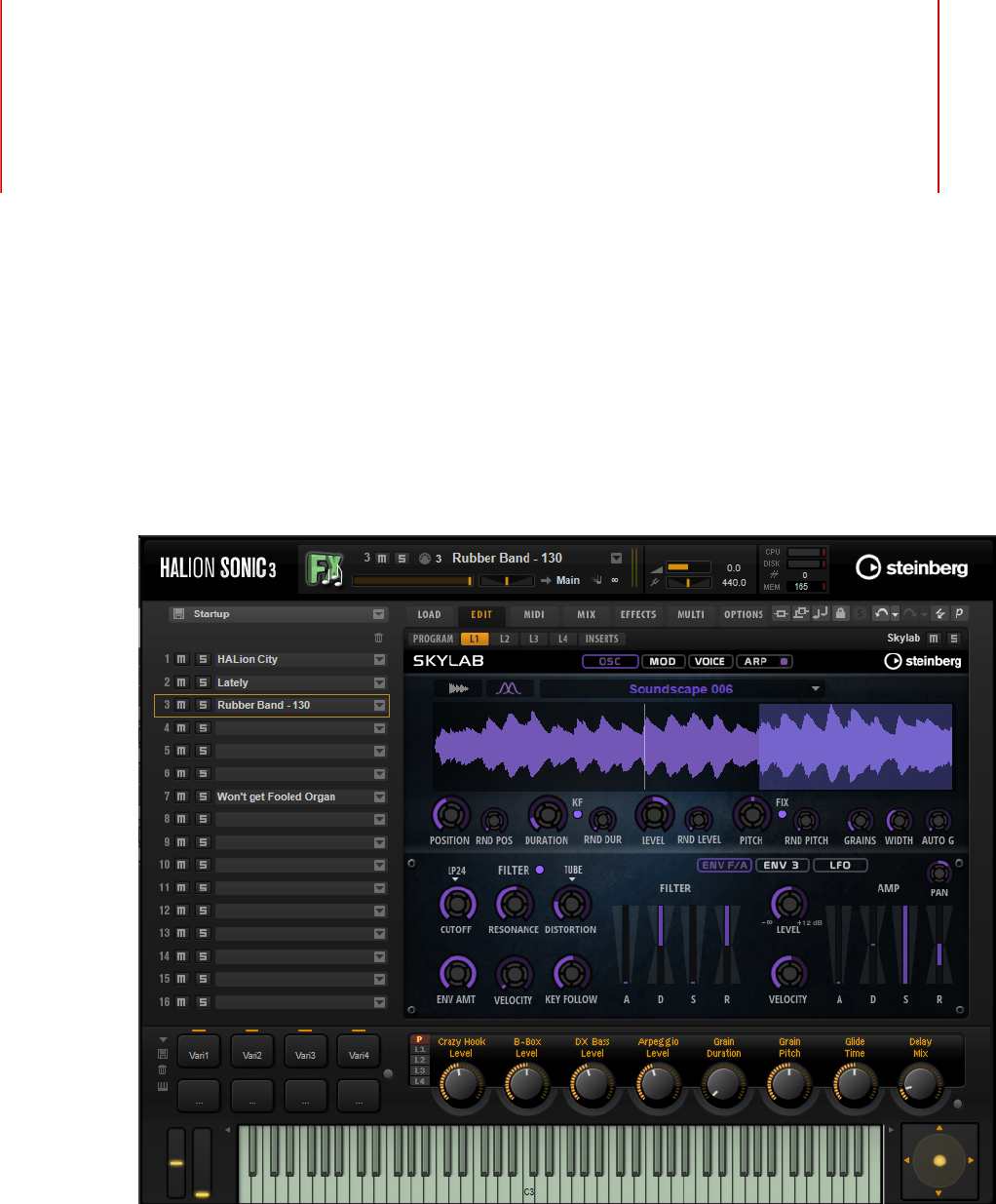
171 Skylab
185 Raven
186 Eagle
188 Hot Brass
199 Studio Strings
210 Effects Reference
210 Reverb Effects
214 Delay Effects
215 EQ Effects

Table of Contents
4
217 Filter Effects
225 Distortion Effects
229 Pitch Shift Effects
230 Modulation Effects
241 Dynamics Effects
251 Spatial and Panner Effects
252 Legacy Effects
264 Note Expression
264 Note Expression Editor
266 Library Manager
266 Library Manager Editor
269 Using the Standalone Version of the Plug-In
269 Making Preferences Settings
269 Preferences Dialog
271 Selecting the MIDI Input and the Audio
Output
271 Scratch Pad
273 Loading a MIDI File
274 Saving a MIDI File
274 Master Volume
275 Index

Installation and Setup
5
Conventions
In our documentation, we use typographical and markup elements to structure information.
Typographical Elements
The following typographical elements mark the following purposes.
PREREQUISITE
Requires you to complete an action or to fulfill a condition before starting a
procedure.
PROCEDURE
Lists the steps that you must take to achieve a specific result.
IMPORTANT
Informs you about issues that might affect the system, the connected hardware,
or that might bring a risk of data loss.
NOTE
Informs you about issues that you should consider.
EXAMPLE
Provides you with an example.
RESULT
Shows the result of the procedure.
AFTER COMPLETING THIS TASK
Informs you about actions or tasks that you can undertake after completing the
procedure.
RELATED LINKS
Lists related topics that you can find in this documentation.

Installation and Setup
System Requirements
6
Markup
Bold text indicates the name of a menu, option, function, dialog, window, etc.
EXAMPLE
In the header of the plug-in panel, click the Preset Management button next to the preset
name field and select Load Preset.
If bold text is separated by a greater-than symbol, this indicates a sequence of different
menus to open.
EXAMPLE
To save a specific layer, right-click it and select Load/Save> Save Layer As.
Key Commands
Many of the default key commands, also known as keyboard shortcuts, use modifier keys,
some of which are different depending on the operating system.
For example, the default key command for Undo is Ctrl-Z on Windows and Cmd-Z on Mac OS.
When key commands with modifier keys are described in this manual, they are shown with
the Windows modifier key first, in the following way:
•Windows modifier key/Mac OS modifier key-key
EXAMPLE
Ctrl/Cmd-Z means: press Ctrl on Windows or Cmd on Mac OS, then press Z.
System Requirements
Your computer must meet the following minimum requirements:
Mac
•Mac OS X Version 10.11/macOS 10.12
•VST 3, AAX, or AU compatible host application for using HALion Sonic as a
plug-in
•64-bit Intel or AMD mutli-core processor (Intel i5 or faster recommended)
•4 GB RAM (8 GB recommended)
•40 GB of free hard-disk space
•Display resolution of 1366 x 768 pixels (1920 x 1080 recommended)
•OS-compatible audio hardware*
•Internet connection required for activation, account setup, and personal/
product registration
•Downloads are required for the installation
*ASIO-compatible audio hardware recommended for low-latency performance

Installation and Setup
Downloading Program Files
7
Windows
•64-bit Windows 7*/8.x/10
•VST 2, VST 3, or AAX compatible host application for using HALion Sonic as
a plug-in
•64-bit Intel or AMD mutli-core processor (Intel i5 or faster recommended)
•4 GB RAM (8 GB recommended)
•40 GB of free hard-disk space
•Display resolution of 1366 x 768 pixels (1920 x 1080 recommended)
•OS-compatible audio hardware**
•Internet connection required for activation, account setup, and personal/
product registration
•Downloads are required for the installation
*Windows 7 Service Pack 1, Microsoft.NET Framework 4.0 and Platform Update
for Windows
**ASIO-compatible audio hardware recommended for low-latency performance
Downloading Program Files
The Steinberg Download Assistant helps you download the required files to your computer.
1. Start the Steinberg Download Assistant.
2. On the left, select the program that you want to install.
3. On the right, select which version you want to install.
You can install a new program, update an existing program, etc.
4. Click Download to download the files.
Installing the Program
After downloading the required files, you can install HALion Sonic on your computer.
•On Windows systems, double-click the product installer and follow the instructions
on screen.
•On a Mac, double-click the file HALion Sonic.pkg and follow the instructions on
screen.
Activating Your License
HALion Sonic uses a software-based copy protection scheme. This Soft-eLicenser is
installed automatically with HALion Sonic. It can be accessed via the eLicenser Control
Center application that is installed automatically with the product.
After installation, you must activate your product.
If you purchased HALion Sonic in a shop, the product package contains a “Download Access
Code” that allows you to download both the software and the license of the product.
If you purchased the download version of HALion Sonic, you receive an e-mail with the
activation code and a description of the activation process.

Installation and Setup
Registering Your Software
8
IMPORTANT
The process for license activation is described in detail on the Steinberg web site.
Registering Your Software
Register your product at the MySteinberg online customer portal. As a registered user,
you are entitled to technical support, you gain access to exclusive offers such as software
updates and upgrades, and more.
PROCEDURE
1. Start your software.
2. Select Help> Register now.
An online registration form opens in your web browser.
3. Follow the instructions on screen to register at MySteinberg.
How You Can Reach Us
Click the Steinberg logo in the top right corner of the control panel to open a pop-up menu
containing items for getting additional information and help.
•This menu contains links to various Steinberg web pages. Select a link to open
the corresponding page. On the web pages, you can find support and compatibility
information, answers to frequently asked questions, links for downloading new drivers,
etc.
•You also find a menu item for the registration of your product.
As a registered user, you are entitled to technical support, you gain access to exclusive
offers such as software updates and upgrades, and more.
About the Documentation
The documentation is available online and most of it can be downloaded in PDF format from
steinberg.help.
•To visit steinberg.help, enter steinberg.help in the address bar of your web
browser or open HALion Sonic, click the Steinberg logo in the top right corner and
select Help> HALion Sonic Help.
Setting Up
The following sections describe how to use HALion Sonic as a plug-in in different host
applications.
NOTE
HALion Sonic can also be used as a standalone application.

Installation and Setup
Setting Up
9
Selecting Outputs
HALion Sonic loads with a stereo output configuration by default. However, you can use up to
15 additional outputs in the Steinberg DAW. This allows you to route all 16 program slots to a
dedicated channel in the MixConsole.
PROCEDURE
1. To make the outputs available in the VST instrument, open the VST Instruments
window.
2. Click the Activate Outputs button for the instrument.
3. Activate the outputs that you want to use.
RESULT
The Steinberg DAW automatically adds an output channel for each additional output to
the MixConsole. You can now route programs or layers to these outputs for further signal
processing within the DAW.
Using the Instrument in an AU-Compatible Application
The AU version of HALion Sonic is installed in your AU plug-ins folder and lets HALion Sonic
work in an AU environment without any performance loss or incompatibilities.
For example, to load HALion Sonic as an AU instrument for Logic Pro, proceed as follows:
PROCEDURE
1. Open the Track Mixer and select the instrument channel that you want to use.
2. Click in the I/O field and select AU Instruments> Steinberg> HALion Sonic.
3. Select one of the available channel configurations.
Using the Instrument as Standalone Application
HALion Sonic can be used as a standalone application, independently of any host application.
In this case, you can connect the instrument directly to your audio hardware.
RELATED LINKS
Using the Standalone Version of the Plug-In on page 269
Introduction
10
Window Overview
The application interface follows a fixed-size single window concept.
The window is subdivided into several sections:
• The plug-in functions section at the top of the application window.
• The multi program rack on the left.
• The toolbars above the edit display.
• The edit display on the right. It contains the Load, Edit, MIDI, Mix, Effects, Multi, and
Options pages.
• The performance section at the bottom. It contains the trigger pads, the quick controls,
the performance controllers, and the sphere control.

Introduction
Window Overview
11
• If you are using the standalone version of HALion Sonic, you find a number of specific
functions in an extra section at the top of the application window.
View Options
You have two view options: the full-size editor view and the smaller player view. In the player
view, only the plug-in functions, the trigger pads, the quick controls, and the performance
controllers are visible.
• Click the p button in the toolbar above the edit display to switch between the views.
When the player view is active, the button changes to e, indicating that clicking again
lets you return to the editor view.

Common Editing Methods
12
Dials and Sliders
Dials and sliders can be unidirectional or bidirectional. Unidirectional values, for example
level values, start at a minimum value and go up to the maximum. Bidirectional controls
start from the middle position and go to the left for negative and to the right for positive
values.
Most of the editing methods are the same for dials and sliders.
• To adjust a value, click a dial or a fader and drag up and down, or use the mouse
wheel.
If you press Alt when clicking a dial, a small fader appears, allowing you to set the
parameter.
• To make fine adjustments, press Shift and move the dial or use the mouse wheel.
• To restore the default value for a parameter, press Ctrl/Cmd and click on the control.
Buttons
On/Off Buttons
These buttons have two states: on and off. If you move the mouse over an On/Off button, it
changes its appearance to show that you can click it.
Push Buttons
Push buttons trigger an action and then go back to their inactive state. These buttons open
menus or file dialogs.
Value Fields
To set a value, you have the following possibilities:
• Double-click in a value field, enter a new value, and press Enter.
If the entered value exceeds the parameter range, it is automatically set to the
maximum or the minimum value, respectively.
• Click in the value field and drag up or down.
• Position the mouse over a value field and use the mouse wheel.
• Click the up/down triangles next to the field.

Common Editing Methods
Using Key Commands
13
• To set the parameter to its default value, Ctrl/Cmd-click the value field.
• To use a fader to adjust the value, Alt-click a value field.
• To enter musical values, such as key ranges or the root key, with your MIDI keyboard,
double-click the value field, press a key on your MIDI keyboard, and press Return.
• To navigate to the next parameter, press Tab. To jump backwards to the previous
parameter, press Shift-Tab.
If no parameter is selected inside the focused view, pressing Tab always jumps to the
first parameter.
Using Key Commands
The commands are arranged in a hierarchical folder structure on the left. When you open
a category folder, the items and functions are displayed with any currently assigned key
commands.
• To set up a key command, select the function in the list, enter the key command in
the Type in Key field and click the Assign button to the right of the field. If this key
command is already used for another function, this is displayed in the field below.
• To delete a key command, select the function in the list, select the key command in the
Keys list and click the Delete button.
• To search for a specific function, enter its name in the search field at the top of the
dialog and click the search button.
NOTE
You can set up several key commands for the same function.
Presets
HALion Sonic offers two types of presets: section/module presets and VST presets. Section
and module presets store and recall the setup of a specific component on the HALion Sonic
panel. VST presets contain all information necessary to restore the complete state of the
plug-in.
During setup, the factory presets are installed in a dedicated folder and a user folder is
created for your own presets. The handling of presets is the same throughout the program.
NOTE
Factory presets are write-protected, but may be overwritten when a software update is
executed. Presets in your user folder are never changed by the software update.
For more information on VST presets, see the Operation Manual of your Steinberg DAW.
Handling Section and Module Presets
The preset controls can be found throughout the program. The handling is always the same.
• To save a preset, click Save .
Common Editing Methods
Presets
14
NOTE
You cannot overwrite factory presets. If you want to save changes made to a factory
preset, save the preset under a new name or in a new location.
• To load a preset, click the arrow icon and select a preset from the list.
• To delete a preset, click Delete .
NOTE
Factory presets cannot be deleted.
Handling VST Presets
Loading VST Presets
PROCEDURE
1. In the header of the plug-in panel, click the Preset Management button next to the
preset name field and select Load Preset.
2. Do one of the following:
•Select a preset to load it.
•Double-click a preset to load it and close the preset loader.
Saving VST Presets
PROCEDURE
•In the header of the plug-in panel, click the Preset Management button next to the
preset name field and select Save Preset.

Global Functions and Settings
15
Plug-in Functions Section
The plug-in functions section at the top of the window gives you access to global functions
that affect both the currently loaded programs, and the general working of the plug-in.
The plug-in functions section contains the multi slot section, the program slot section, the
master section, and the performance displays.
Program Slot Section
This section contains a copy of the slot that is selected in the multi program rack, as well as
the main parameters of the program.
The slot parameters are the same as in the multi program rack. In addition, the following
parameters are available:
Slot Number
The number of the active slot. You can switch to another slot by clicking the slot
number and selecting an entry from the list.
NOTE
Only slots that contain programs are available on the list.
Load Icon
Click the Load icon to the right of the slot to open the program loader. Double-
click a program to load it.
MIDI Activity Indicator
The MIDI symbol starts blinking when incoming MIDI data is detected.
Level
Adjusts the output level of the slot.
Pan
Adjusts the position of the slot in the stereo panorama.
Output
On the output selector, you define the output destination of the slot signal.

Global Functions and Settings
Plug-in Functions Section
16
Polyphony
Sets the number of keys that can be played simultaneously.
NOTE
One key can trigger several layers. On the performance meter, you can see how
many voices are triggered by your playing.
Program Icon
The program icon indicates the sound category to which the program belongs. It
depends on the category and subcategory tags that are specified for a program in
the MediaBay.
Master Section
The master section can be used to set volume and tuning of the plug-in.
Master Volume
Adjusts the overall volume of the plug-in.
Master Tune
You can set the Master Tune slider from 415.3 Hz to 466.2 Hz, which equals -100
cents to +100 cents.
Performance Displays
The meters and text displays indicate the system load of the plug-in.
CPU
This meter shows the processor load during playback. The more voices you play,
the higher the processor load. If the overload indicator lights up, reduce the Max
Voices setting on the Options page.
Disk
This meter shows the hard disk transfer load during the streaming of samples
or when loading presets. If the overload indicator lights up, the hard disk is not
supplying data fast enough. In such a case, open the Options page and adjust the
Disk vs. RAM slider towards RAM or decrease the Max Voices setting.
Polyphony
This display indicates the number of samples that are currently played back, to
help you trace performance problems. For example, if you have to reduce the Max
Voices setting on the Options page, you can verify your settings by monitoring the
number of samples that are currently playing.
Memory
This display indicates the overall amount of RAM that is currently used by the
plug-in and the loaded programs. The number refers to the streaming buffer and
the preloaded samples. The MEM display helps you trace performance problems.
For example, if you need to free up memory for other applications, you can adjust

Global Functions and Settings
Plug-in Name and Steinberg Logo
17
the Disk vs. RAM slider on the Options page toward Disk. You can verify your
settings by monitoring the MEM display.
Plug-in Name and Steinberg Logo
To get information regarding the version and build number of the plug-in, click the plug-
in logo. This opens the About box. To close the About box, click it or press Esc on your
computer keyboard.
If you click the Steinberg logo in the top right corner of the plug-in interface, a pop-up menu
opens. Select one of the options to navigate to Steinberg web pages containing information
on software updates, troubleshooting, etc.
Toolbar
The toolbar below the plug-in functions section contains controls for loading multi-programs
on the left, the buttons to switch between the different pages, and various useful global
functions.
Global insert, AUX, and FlexPhraser buttons
Use these buttons to switch off all insert effects, AUX effects, and FlexPhrasers
for the whole plug-in at once. You can use this to compare sounds with and
without effects or to use a preset without the FlexPhrasers, for example.
Lock button
If this button is activated, loading another program or layer does not overwrite
the current FlexPhraser and trigger pad settings.
MIDI Reset
Click this button to stop playback and reset all MIDI controllers to their default
values.
Undo/Redo
To undo or redo a single operation, click the Undo or Redo buttons. To undo or
redo multiple operations, click the arrow next to the button to open the history
and select the step to which you want to return.
Editor/Player
This button toggles between the two views: the full-size editor view (e) and the
smaller player view (p).
Performance Controls
The performance controls are located in the lower part of the window.
Global Functions and Settings
Quick Controls
18
Wheel Controls
To the left of the internal keyboard, the pitchbend wheel and the modulation wheel are
located.
The modulation wheel is hardwired to MIDI controller #1, which is normally used as a source
in the modulation matrix, but can be used as a quick control as well.
Keyboard
The virtual 88-note keyboard can be used to trigger MIDI notes. By clicking the keys at
different vertical positions you can control the note-on velocity. Furthermore, the keyboard
displays keys that are not used to trigger notes but act as key switches. The Shift Keyboard
buttons to the left and right of the keyboard shift the keyboard range by octaves. This allows
you to display key switches that are located on lower keys, for example.
Sphere Control
The sphere is a two-dimensional control. It allows you to adjust two parameters
simultaneously, by dragging the mouse horizontally (Sphere H) and vertically (Sphere V).
Typically, two parameters that belong together are assigned to the sphere, such as cutoff and
resonance.
If parameters are assigned to Sphere H and Sphere V, triangles for indicating the horizontal
and vertical axis are available.
You can reset the sphere to the center position using the corresponding options on the
context menu.
• If Center Horizontal and/or Center Vertical are activated, the sphere returns to the
corresponding center position as soon as you release the mouse button.
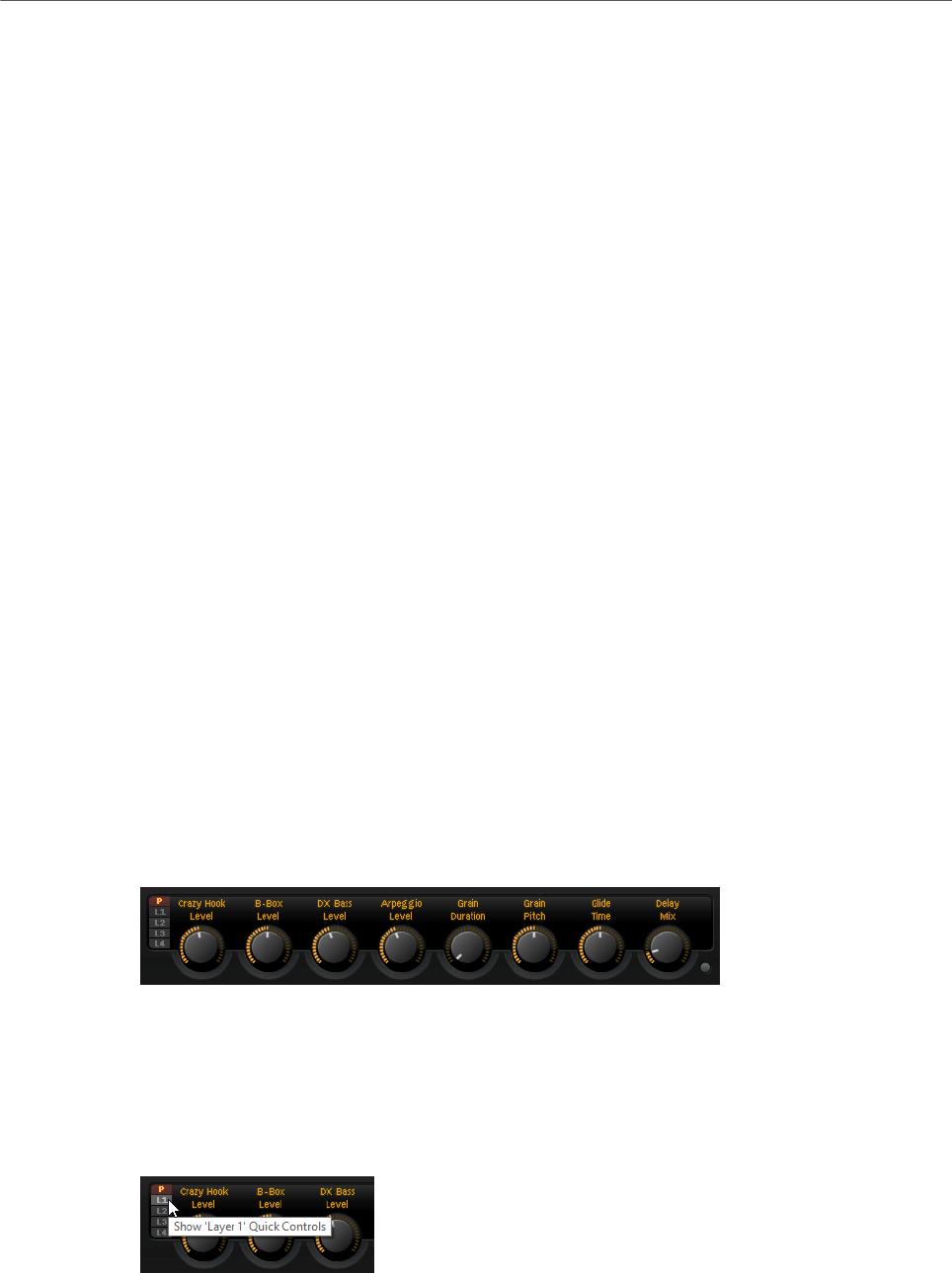
Quick Controls
Quick controls allow you to remote-control any parameter inside the program.
For each program and layer, eight quick controls are available. Furthermore, Sphere H,
Sphere V, and the modulation wheel can also serve as quick controls.
If a layer contains zones, these zones are also affected by the quick controls of the layer.
•To switch between the quick controls of the program and the layers, use the buttons to
the left of the potentiometer controls.
Value Tooltips
If you use quick controls, the following situations can happen:

Global Functions and Settings
Quick Controls
19
•The actual value of a parameter and the value that is displayed in its value field differ.
•A button on the user interface is deactivated but the corresponding parameter is
active.
For example, this can happen if the quick control introduces an offset or if a button is
controlled by a quick control.
Therefore, parameters that are assigned to a quick control show a value tooltip. This value
tooltip indicates the resulting parameter value and the name of the assigned quick control.
Value tooltips can be activated or deactivated on the Options page.
RELATED LINKS
Global Section on page 29
Accessing Quick Controls
PROCEDURE
1. Select the program that you want to edit in the multi program rack.
2. Use the buttons to the left of the quick controls to select whether you want to access
the quick controls for the program or for one of the layers.
The quick controls change to the settings of the program or the selected layer.
Assigning Quick Controls
PROCEDURE
1. In the editor for a program, a layer, or an insert effect, right-click the control to which
you want to assign a quick control.
NOTE
•Parameters of a layer can only be assigned to the quick controls of this layer.
•If you want to assign the parameters of a layer to the quick controls of a
program, you must first assign the parameter to a quick control of the layer, and
then assign the quick control of the layer to a quick control of the program.
2. On the Assign Quick Control submenu, select the quick control that you want to assign.
RESULT
The assignment is created.
NOTE
You can also assign a quick control as modulation source or modulation modifier in the
modulation matrix. This allows you to combine the quick control with other modulation
sources.

Global Functions and Settings
Quick Controls
20
RELATED LINKS
Modulation Matrix Parameters on page 67
Setting the Minimum/Maximum Range
You can set the minimum and maximum range for each assignment separately. This gives
you better control over the parameter change.
•Right-click a control and define the range using the Set Minimum and Set Maximum
commands.
•In the Quick Control Assignments editor, enter the values in the Minimum Value and
Maximum Value fields or click and drag the handles in the curve display.
Trimming the Range
The Trim Range function allows you to automatically set the best quick control range,
depending on the current parameter value.
PROCEDURE
•In the Quick Control Assignments editor, right-click the assignment in the list on the
right.
•To trim the range of a single assignment, select Trim Range.
•To trim the range of all quick controls, select Trim Range of All Quick Controls.
RESULT
The minimum and maximum values are set automatically.
NOTE
If you change the original parameter, you have to apply the Trim Range function again to
guarantee the best control range.
Setting the Default Range
PROCEDURE
•In the Quick Control Assignments editor, right-click the assignment on the right.
•To set the default range of a single assignment, select Set Default Range.
•To set the default range of all quick controls, select Set Default Range of All
Quick Controls.
RESULT
The quick controls are set to their maximum possible range.
NOTE
If you change the original parameter, you must apply the Set Default Range function again to
guarantee the best control range.
Global Functions and Settings
Quick Controls
21
Unassigning Quick Controls
PROCEDURE
•Do one of the following:
•To remove a quick control assignment, right-click the parameter in the Quick
Control Assignments editor and select Remove Assignment.
•To remove all assignments of the selected quick control, open the context menu
and select Remove All Assignments.
•To remove all quick control assignments for all 8 quick controls, select Remove
All Assignments of All Quick Controls.
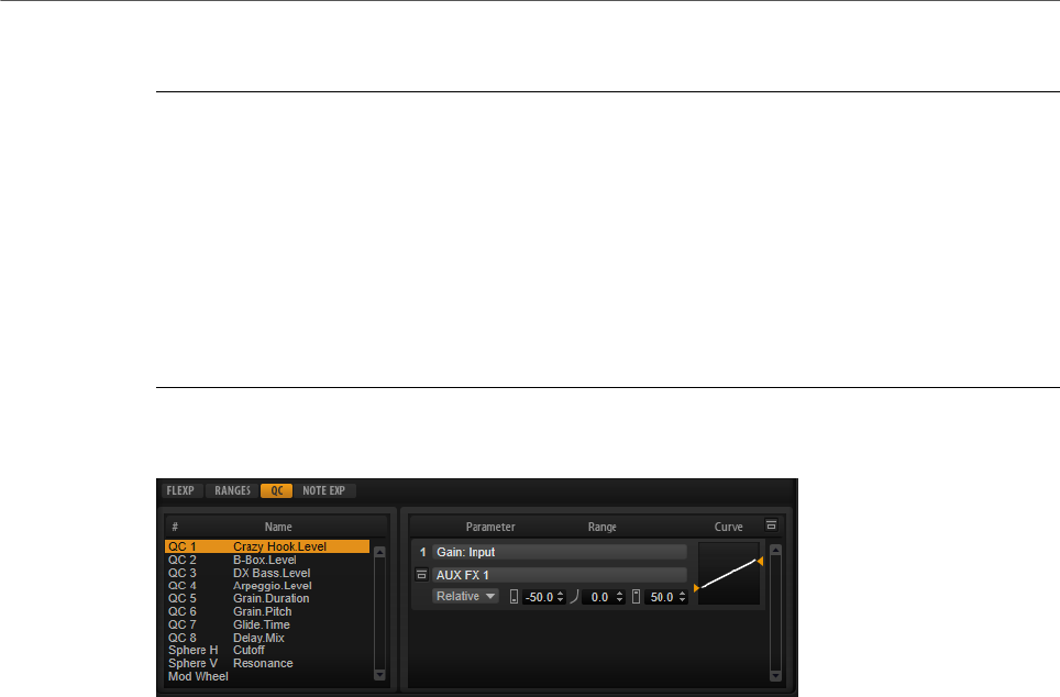
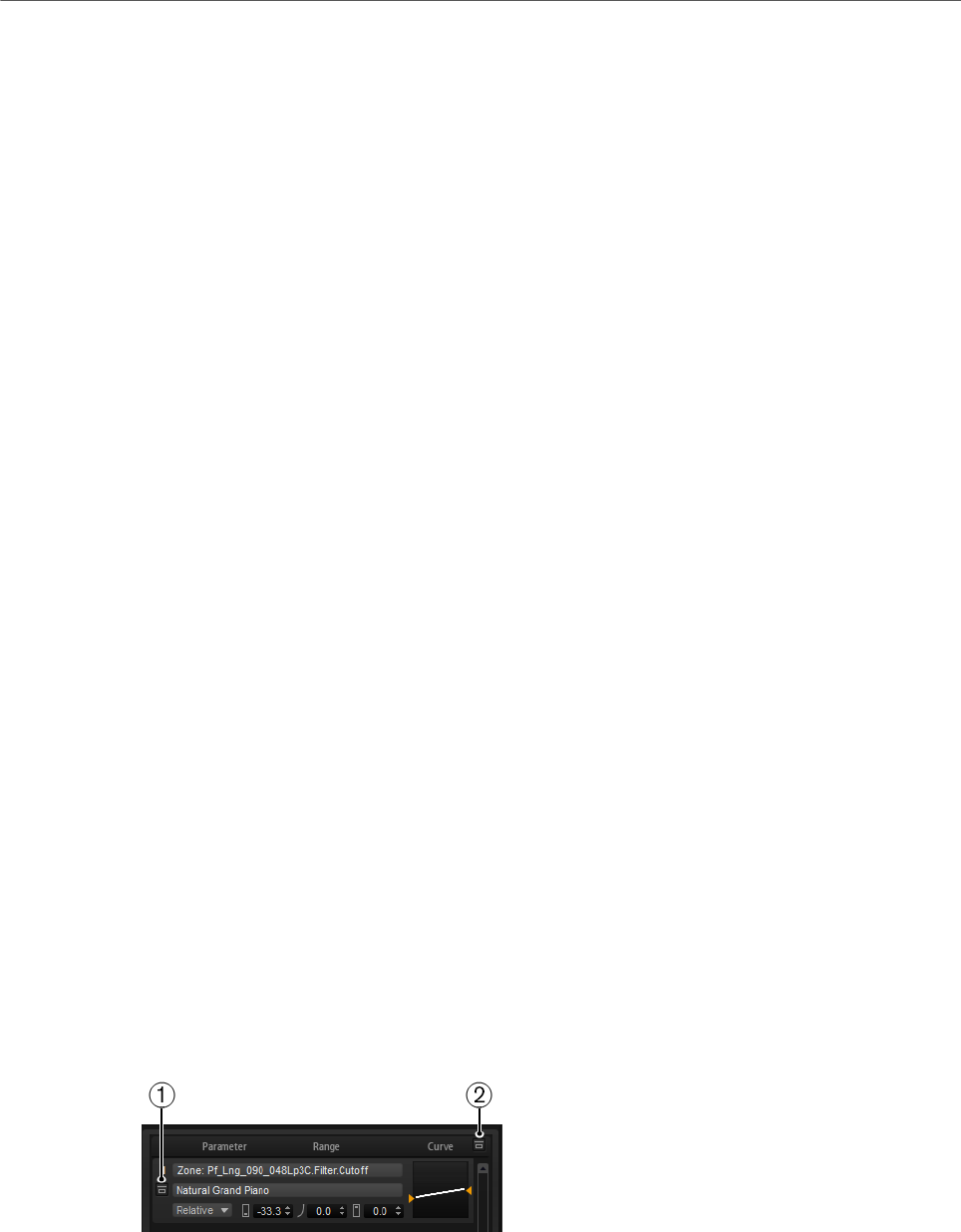
Quick Control Assignments Editor
• To open the Quick Control Assignments editor, right-click a quick control and select
Edit Quick Control or open the Edit page for a program and select the QC tab in the
lower part of the page.
Bypass All Quick Control Assignments
Allows you to hear a sound without quick control assignments.
Quick Controls List
The eight quick controls are listed on the left. The assignments of the selected
quick control are listed on the right. You can edit the parameters for each
assignment separately.
Quick Control Parameter
Displays the parameter assignment for the selected quick control.
Affected Layers/Modules
Displays which program, layer, or module is affected by the quick control.
Bypass Single Quick Control Assignment
Bypasses the corresponding quick control assignment.
For example, if a quick control is assigned to several layers, this option allows
you to bypass the quick control assignment for one of the layers only.
Mode
Determines the mode that is used for changing the parameter values.

Global Functions and Settings
Quick Controls
22
Minimum Value
Sets the minimum value for the quick control assignment.
Curvature
Sets the curvature. You can also set the curvature by clicking and dragging in the
curve display.
Maximum Value
Sets the maximum value for the quick control assignment.
Bypass All Quick Control Assignments
Bypasses all assignments for the selected quick control.
RELATED LINKS
Setting the Mode for the Quick Control Assignment on page 23
Adjusting the Curvature on page 22
Bypassing Quick Controls on page 23
Managing Quick Controls
The Quick Control Assignments editor allows you to manage and edit assigned quick
controls.
•To rename a quick control, click in the Name column and enter a new name.
•To change the order of quick control assignments, drag an assignment between two
other quick controls. When a line is shown, release the mouse button to insert the
quick control assignment.
•To replace a quick control assignment, drag it onto another quick control. When a
rectangle is shown, release the mouse button to replace the quick control assignment.
Adjusting the Curvature
You can adjust the curvature of each assignment in the Quick Controls Assignment editor
separately.
PROCEDURE
•To adjust the curvature, do one of the following:
•Select the quick control that you want to edit and specify a value in the Curvature
value field.
Positive values change the curvature towards logarithmic behavior and negative
values towards exponential behavior.
•Click and drag the curvature in the display on the right.
Global Functions and Settings
Quick Controls
23
Setting the Mode for the Quick Control Assignment
A quick control behaves either as continuous control or as a switch. In addition, it remote-
controls a parameter either in relative or absolute mode. You can specify a mode for each
assignment.
You can set the behavior in the context menu for the control itself or via the pop-up menu in
the Quick Control Assignments editor.
Absolute
Remote-controls the parameter values continuously. Absolute mode changes the
assigned parameters by overwriting them with the current quick control value,
that is, parameter changes are overwritten.
Relative
Remote-controls the parameter values continuously. Relative mode changes the
values of the assigned parameters without losing their relative settings, that is,
parameter changes can still be heard.
Switch Relative
Switches between the minimum and maximum value. Parameter changes can
still be heard.
Neutral Setting
If you adjust the range of a quick control assignment, it can become necessary to change its
neutral setting, to prevent the resulting sound from changing.
If you adjust the range of a quick control that has a single assignment that uses Absolute or
Relative mode, HALion Sonic adjusts the setting of the quick control automatically so that
the sound does not change. Likewise, if you assign multiple parameters to the same quick
control, HALion Sonic sets the range of this quick control assignment automatically.
However, if a quick control has multiple assignments and you change the range of one or
more assignments, the neutral setting cannot be set automatically. In this case, you can
specify the neutral setting manually using the Set Quick Control to Neutral Setting command
on the context menu for the quick control.
Bypassing Quick Controls
Bypassing quick controls allows you to hear a sound without quick control assignments.
1. To bypass a single assignment for one quick control, click Bypass Single Quick Control
Assignment in the Quick Control Assignments editor.
2. To bypass all assignments for one quick control, select the quick control in the Quick
Control Assignments editor, and click Bypass All Quick Control Assignments in the
upper right of the parameter section.
Global Functions and Settings
Trigger Pads
24
Assigning Quick Controls in the Modulation Matrix
In addition to assigning the quick controls directly to parameter controls, you can also assign
them as source or modifier in the modulation matrix. This way, you can combine the quick
control with other modulation sources.
PROCEDURE
1. Open the layer editor and go to the modulation matrix.
2. On the pop-up menu in the Source/Modifier column, open the Assign Quick Control
submenu and select the quick control.
The submenu lists the quick controls of the layer.
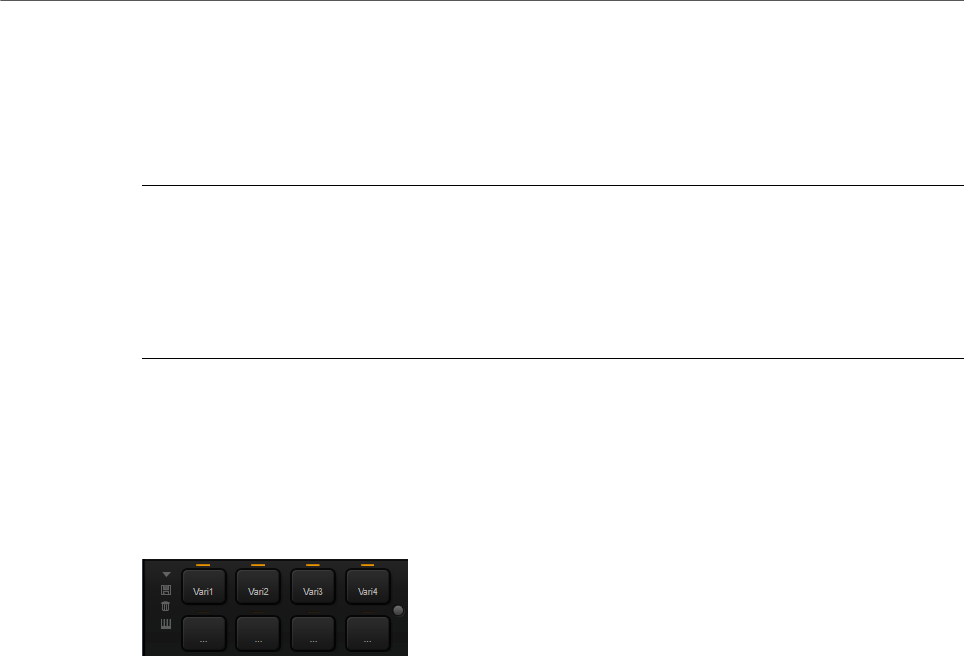
Trigger Pads
You can use the trigger pads to trigger single notes or whole chords and to switch between
FlexPhraser variations.
Many of the programs that come with HALion Sonic make use of the trigger pads.
If a note or a chord is assigned to a pad, this pad turns orange. If a pad switches between
FlexPhraser variations, the line above the pad turns orange.
•To trigger a pad, click on it.
Presets
Pad presets save trigger notes and chord snapshots, but not FlexPhraser
snapshots. This means that you can exchange trigger notes and chords by
loading presets without loosing your FlexPhraser snapshots.
Bypass
With the Bypass Pads button to the right of the trigger pads, you can bypass the
entire pads section. This deactivates any functionality you assigned to the trigger
pads.
Assigning Trigger Notes to Pads
You can assign a MIDI note to a pad and trigger the pad by playing this note.
To define the trigger note, do one of the following:
•Right-click a pad, open the Assign Trigger Note submenu, and from the further
submenus, select the octave and note that you want to assign.
•Open the context menu for a pad, select Learn Trigger Note, and play the note on your
MIDI keyboard or click a key on the internal keyboard.
The name of the assigned trigger note is displayed in the top left corner of the pad.
On the internal keyboard, keys that serve as trigger notes are shown in blue. These keys do
not play sounds, but trigger the corresponding pads instead.

Global Functions and Settings
Trigger Pads
25
•To remove a trigger note from a pad, right-click the pad and select Forget Trigger
Note.
Assigning Chords or Notes to Trigger Pads
PROCEDURE
1. Right-click a pad and select Snapshot Chord.
The pad starts blinking.
2. Do one of the following:
•Play a chord or a single note and then click the pad that is blinking to assign the
chord or note to the pad.
•Drag a chord event from the chord track of your Steinberg DAW onto a trigger
pad. This transfers the corresponding MIDI notes to the pad.
If you drag a chord event onto the internal keyboard first, the corresponding
chord is played back. This is useful to verify whether you selected the correct
chord.
If you define a chord that contains a key switch, you can trigger the chord with a
specific instrument expression.
If you add keys to a chord that also work as trigger notes, they trigger the underlying
MIDI note instead of the trigger note.
RESULT
Triggering the pad now plays the chord or note.
Default Trigger Note Settings
Assigned trigger notes are saved with each program to allow for maximum flexibility.
However, you can save a fixed set of default trigger notes to reflect an existing hardware
setup, for example.
•To specify a default set of trigger notes, set up the trigger notes for all pads, right-click
a pad, and select Save Trigger Notes as Default.
•To activate the default trigger note settings, right-click a pad and select Use Default
Trigger Notes.
Now, changing programs or multi-programs does not change the trigger notes
anymore.
If you deactivate Use Default Trigger Notes, the last set of trigger notes remains active. To
return to the trigger notes that were saved with the program, reload the program.
Assigning Key Switches to Trigger Pads
To use the pads for switching between expressions, assign them to the corresponding key
switches.
PROCEDURE
•Right-click a pad, select Snapshot Chord, and play the key switch.

Global Functions and Settings
Options Page
26
Removing Chords or Notes from Trigger Pads
PROCEDURE
•Right-click the trigger pad and select Clear Chord.
Switching between Variations
You can switch between variations using the trigger pads.
Variations are available for the FlexPhraser and the B-Box, for example.
PROCEDURE
1. Right-click the trigger pad that you want to use for switching to the selected
FlexPhraser variations.
2. On the menu, select Snapshot Variation.
The line above the pad turns orange to indicate that a FlexPhraser snapshot is
assigned.
RESULT
If you trigger the pad, it switches to the variation that was selected when you made the
snapshot.
NOTE
Instead of saving the variation settings themselves, the trigger pad saves only the variations
that were selected when you made the snapshot. This allows you to modify variations after
creating the snapshot. However, if you replace or add layers, you must first remove the
assignment using the Clear FlexPhrasers command on the context menu and then take the
FlexPhraser snapshot again.
RELATED LINKS
Creating FlexPhraser Variations on page 82
B-Box on page 139
Naming Pads
Entering names for pads allows you to get a better overview of their functionality, for
example.
PROCEDURE
1. Right-click the pad to open the context menu and select Rename Pad.
2. Enter the new name and press Enter.
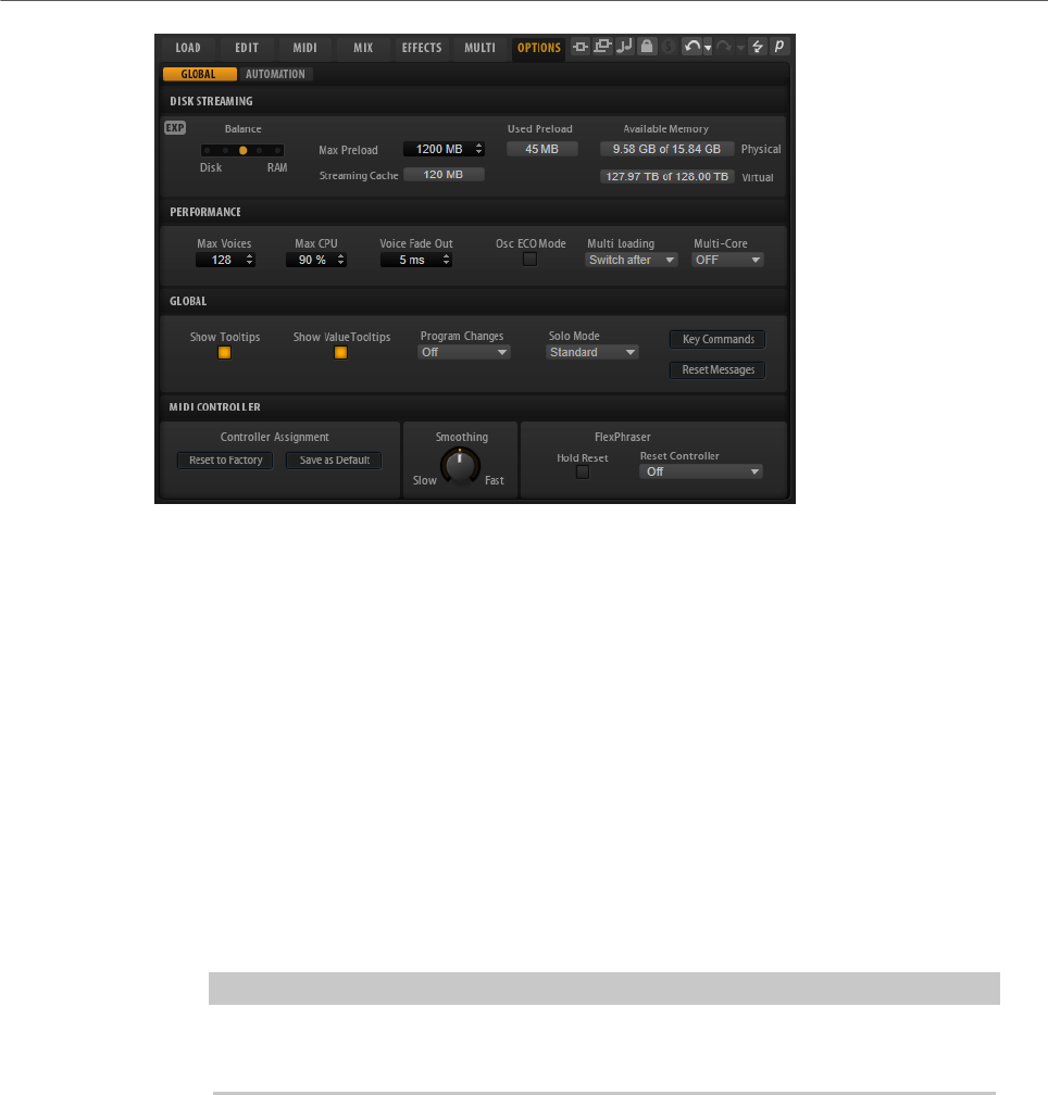
Options Page
The Options page contains global settings regarding performance optimization, global
functions, and MIDI controllers.
Global Functions and Settings
Options Page
27
Disk Streaming Section
Some of the programs come with up to 1 GB of samples. That is a large amount of data and
your computer cannot load all samples completely into the RAM, especially if you are using
all slots. Therefore, HALion Sonic loads only the initial milliseconds of each sample into
RAM. You can specify how much RAM should be used and how much HALion Sonic should
rely on accessing the hard-disk.
Balancing Disk vs. RAM
Use the Balance slider to balance the hard disk versus the RAM usage.
• If you need more RAM for other applications, drag the slider to the left
towards the Disk setting.
• If your hard disk is not supplying data fast enough, drag the slider to the
right towards the RAM setting.
NOTE
The Disk vs. RAM setting always applies to all plug-in instances. It is not saved
with the project. You set it up only once for your computer system.
Used Preload and Available Memory
These displays provide information of the memory load in MB according to the
current balance slider setting.
Max Preload
Determines the maximum amount of RAM that HALion Sonic uses for preloading
samples. In most cases, the default values are sufficient. However, it may
become necessary to reduce this value, for example, when working with other
applications or plug-ins that require a lot of memory.
Expert Mode
Activate Expert Mode if you want to adjust the Disk Streaming settings in greater
detail.
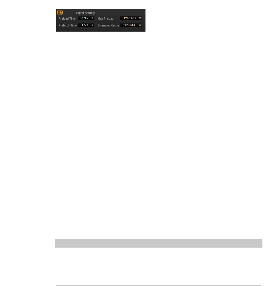
Global Functions and Settings
Options Page
28
•Preload Time defines how much of the start of the samples is preloaded
into the RAM. Larger values allow for more samples to be triggered in a
short time.
•Prefetch Time determines the read-ahead capacity into the RAM while
streaming samples for a voice that is playing. Larger values allow for
better transfer rates from disk, and usually for more voices. However, this
requires larger streaming cache in RAM. If you increase the Prefetch Time,
it is recommended to also increase the Streaming Cache.
•Streaming Cache determines the amount of RAM that is reserved for
prefetching. The actually needed size depends on the prefetch time, the
number of simultaneously streaming voices and the audio format of the
samples. For example, higher sample and bit rates need more RAM.
Performance Section
The Performance section contains settings to optimize the overall CPU performance of the
plug-in.
Max Voices
Determines the total number of voices that a plug-in instance can play back. As
soon as this limit is reached, HALion Sonic starts stealing voices.
Max CPU
To avoid clicks from CPU overloads, you can specify a maximum limit for the CPU
load of the plug-in instance. HALion Sonic steals voices automatically when this
limit is exceeded. At a setting of 100 %, this parameter is deactivated.
NOTE
Because of the reaction time of the plug-in, it is possible that you get CPU peaks
that exceed the set limit. This can lead to artifacts, such as audio drop-outs.
Therefore, it is good practice to set the Max CPU setting at a value a bit lower
than actually needed.
Voice Fade Out
Sets the time to fade out voices that need to be stolen because the Max Voices
setting or the Max CPU setting have been reached.
Osc ECO Mode
Activate this option to run the oscillators of synth layers in ECO mode. In ECO
mode, the oscillators use less CPU at the cost of producing more aliasing at
higher pitches. If this option is activated, you can play more voices with synth
layers.

Global Functions and Settings
Options Page
29
Multi Loading
Normally, when loading multi-programs, the previous multi is kept in the RAM
until the new multi has been completely loaded. Therefore, replacing a large
multi by another can lead to RAM overload on 32-bit systems.
• To clear a multi before loading a new one, select Clear before on the pop-
up menu.
Multi-Core
On this pop-up menu, you can specify how many of the available CPU cores of
your system can be used by the plug-in. This allows HALion Sonic to compute
each program on a different core, for example. The best setting here depends on
multiple factors, and varies from system to system, and project to project. A good
starting point is to set this value to one core less than the available number of
cores.
NOTE
If problems occur, reduce the number of cores, or set the pop-up menu to Off and
load multiple instances of HALion Sonic instead. This way, the host application
distributes the work load across the available cores.
Global Section
Here, you find common settings of HALion Sonic and the General MIDI mode parameter.
NOTE
The settings in this section are not saved with a project, but affect the plug-in as a whole.
Show Tooltips
If this option is activated, a tooltip is shown when you move the mouse over a
control.
Show Value Tooltips
If this option is activated, parameters without a value field display their value in a
tooltip when you use the corresponding control.
Solo Mode
• In Standard mode, you can solo multiple programs or layers to hear them
combined.
• In Exclusive mode, only one program or layer can be soloed at a time.
Program Changes
Determines how HALion Sonic handles incoming MIDI program change
messages.
• In GM Mode, program change messages are used to switch programs in
the slots of the multi program rack.
• In Multi Mode, program change messages are used to switch between the
128 multis that can be configured on the Multi page.
• Select Off to ignore incoming controller change messages.

Global Functions and Settings
Options Page
30
General MIDI Mode
Select General MIDI Mode to play back MIDI files that have been arranged for
General MIDI sound sets. General MIDI mode supports MIDI program change
messages and preloads a global chorus and reverb effect on AUX FX 1 and 3 for
immediate use.
If General MIDI mode is activated, all loaded programs are removed and the 16
slots are assigned to the 16 MIDI channels. As long as General MIDI mode is
active, the 16 MIDI channels on the MIDI page cannot be changed.
The MediaBay sets an instrument set filter and displays only the General MIDI
sounds. The MIDI program changes 0–127 refer to the corresponding GM Sound
attributes of the MediaBay. This means that you can make any of your sounds
part of the General MIDI sound set by setting the GM Sound attribute on the
corresponding sound.
NOTE
The General MIDI sounds that come with HALion Sonic are optimized for fast
loading times. However, larger programs take longer to load.
Key Commands
Opens the Key Commands dialog, where you can view and assign key commands.
Reset Messages
If you click this button, all message dialogs that have been suppressed with the
Don't Show Again option are displayed again.
MIDI Controller Section
Controller Assignment
With the two buttons in this section, you can save your customized MIDI
controller assignments as default or restore the factory MIDI controller
assignments.
NOTE
Save as Default does not include any of the MIDI controller assignments of the
AUX FX.
The current MIDI controller mapping is also saved with each project. This way,
you can transfer your settings to other systems. The project includes the MIDI
controller assignments of the AUX FX as well.
MIDI Controller Smoothing
MIDI controllers have a maximum resolution of 128 steps. This is rather low.
Therefore, if you use a MIDI controller as a modulation source in the modulation
matrix or to remote-control a quick control, the parameter change may occur in
audible steps, causing an effect often referred to as “zipper noise”. To avoid this,
HALion Sonic provides MIDI controller smoothing, so that parameter changes
occur more gradually.

Global Functions and Settings
Options Page
31
• If MIDI controller changes cause audible artifacts, turn the control
towards slower settings. This way, MIDI controller changes do not occur
immediately, but are spaced over a period of time (in milliseconds).
• If you want more immediate MIDI controller changes, turn the control
towards faster settings. Note, however, that this may introduce audible
artifacts.
FlexPhraser
Hold Reset sends a global hold reset message to all FlexPhraser modules that
are used.
The Reset Controller pop-up menu allows you to assign a dedicated MIDI
controller to the Hold Reset button for remote-controlling it.
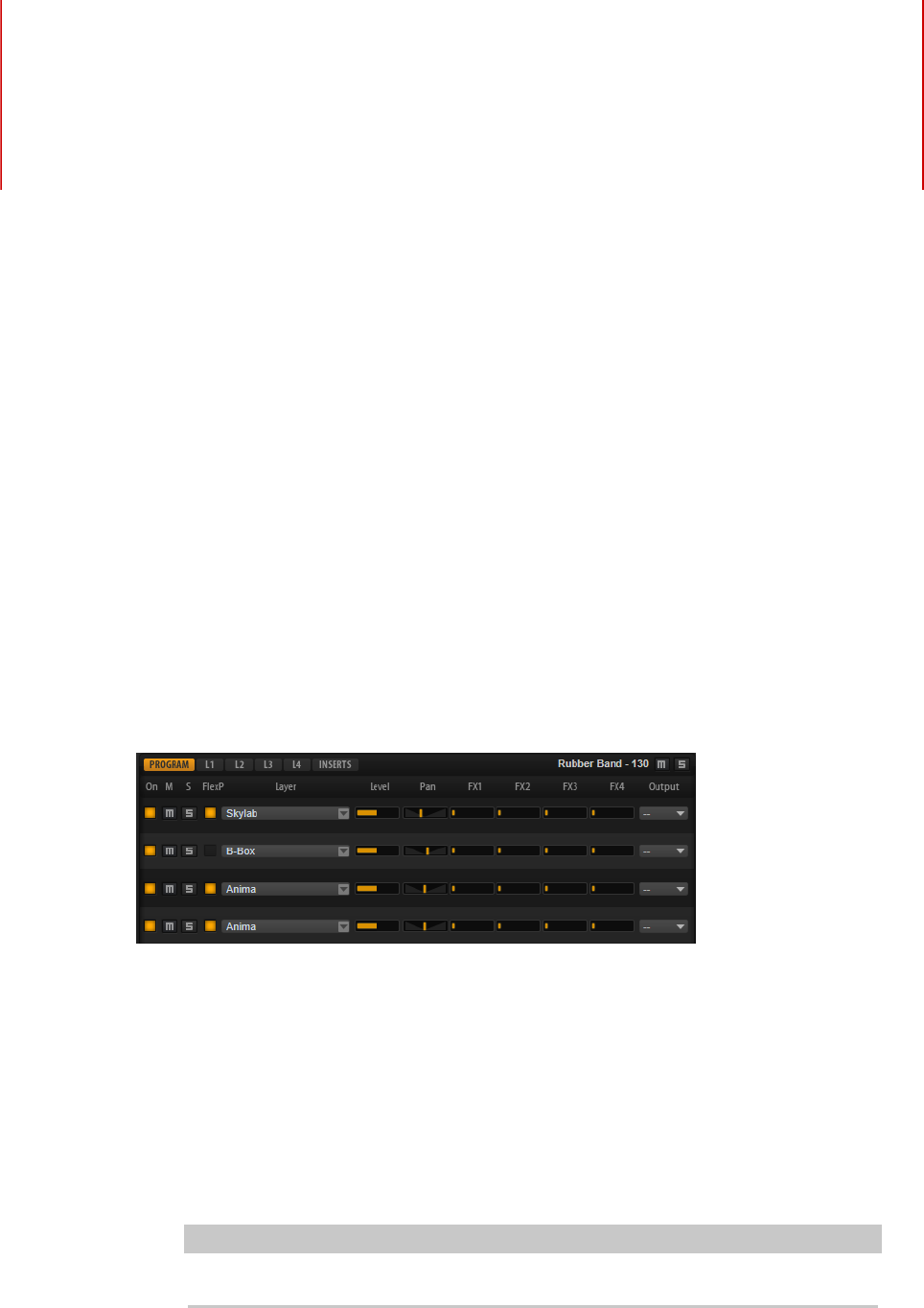
Editing Programs
32
The Edit page is where you edit your program, load different layers for a program, and edit
the layers. A program contains up to four layers that can all be mapped to different velocity
and key ranges. Each of the layers can use a FlexPhraser and can be routed freely to one of
the available outputs.
To edit a program, click the Program button at the top of the Edit page.
Program Page Parameters
The Program page is divided into two sections. The section at the top is used to load
and save layers, and to set up the mix parameters such as level, pan, and FX sends. The
bottom section is used to display layer ranges, program FlexPhraser editors, quick control
assignments, or Note Expression parameters.
On/Off
Activates/Deactivates the corresponding layer. If a layer is deactivated, it does not
use any processing power.
Mute
Mutes the corresponding layer.
Solo
Solos the corresponding layer. You can solo multiple layers at the same time.
NOTE
The Mute and Solo buttons at the top of the page mute the entire program.
FlexPhraser On/Off
Activates/Deactivates the FlexPhraser for a layer.
You can edit the FlexPhraser on the edit page for the corresponding layer.
Editing Programs
Program Page Parameters
33
NOTE
This button is only available for layers that support the FlexPhraser functionality.
Layer Slots
The layer slots allow you to load up to four layers for a program.
Right-click a slot to open the context menu with the following options:
•Load Layer opens the Load Layer dialog. Select a layer and click OK to load
it into this slot.
•Save Layer saves the layer in this slot with the current settings, under the
same name.
NOTE
Write-protected content can only be saved under a new name.
•Save Layer As opens the Save Layer dialog where you can save the layer
under a new name.
•Remove Layer removes the layer from the slot.
•Init Layer loads a neutral synth layer.
•Copy Layer copies the layer to the clipboard.
•Paste Layer pastes the copied layer into the current slot.
Level
Adjusts the loudness of the layer.
Pan
Sets the position of the layer in the stereo panorama.
FX1–4 Send Levels
These four sliders adjust the send levels for the global AUX FX busses for each
layer.
Output
Sets the output for each layer. If you do not change this setting, the signal is sent
to the output that is specified for the program. But you can also select the main
output or one of the plug-in outputs.
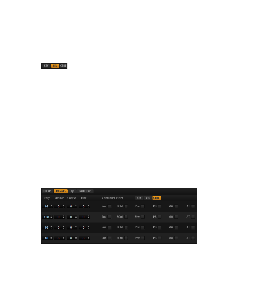
Ranges Tab

Editing Programs
Program Page Parameters
34
Poly
Specifies how many notes can be played at the same time.
NOTE
Polyphony is part of the layer settings and is therefore restored when you load a
layer.
If a layer is monophonic, this setting has no effect.
Octave
Allows you to shift the octave of a layer by ±5 octaves.
Coarse
Allows you to shift the pitch of a layer by ±12 semitones.
Fine
Allows you to detune a layer by ±100 cents.
Key Range (Low Key, High Key)
Allows you to limit the key range for a slot.
Velocity Range (Low Vel, High Vel)
Allows you to limit the velocity range for a slot.
Controller Filter
Allows you to filter out the most commonly used MIDI controllers.
FlexP, QC, and NoteExp Tabs
The FlexP, QC, and NoteExp tabs are described in separate sections.
RELATED LINKS
FlexPhraser on page 76
Quick Controls on page 18
Note Expression on page 264
Editing the Key Range on page 34
Editing the Velocity Range on page 35
Filtering Controllers on page 35
Editing the Key Range
Each slot can be limited to a specific key range.
To show the key range, activate the Key button above the range controls.
You can set the key range in the following ways:
• Set the range with the Low Key and High Key value fields or by dragging the ends of
the keyboard range control.
• To move the key range, click in the middle of the range control and drag.
Editing Programs
Program Page Parameters
35
• To set the range via MIDI input, double-click in a value field and play the note.
Editing the Velocity Range
Each slot can be limited to a specific velocity range.
To show the velocity range, activate the Vel button above the range controls.
• Set the velocity range with the Low Vel and High Vel value fields or by dragging the
ends of the velocity range control.
To move the velocity range, click in the middle of the range control and drag.
Filtering Controllers
You can filter out the most commonly used MIDI controllers for each slot separately.
For example, if you set up a keyboard split with bass and piano playing on the same MIDI
channel, both sounds receive the same MIDI controllers. However, you usually do not want
the bass to receive the sustain pedal. To avoid that all sounds on the same MIDI channel
receive the same MIDI controllers, use the controller filter.
Filtering out control change messages can also be used to avoid unwanted program changes
on MIDI channel 10 (drums), for example.
PROCEDURE
1. Activate the Ctrl button above the range controls.
2. For each slot, activate the MIDI controllers that you want to filter out.
You can filter out the following MIDI controllers: Sustain Pedal #64, Foot Controller #4,
Foot Switches #65-69, Pitchbend, Modulation Wheel #1, and Aftertouch.
Editing Layers
36
A program contains up to four layers. Each layer can be edited separately. The available
parameters and tabs vary depending on the type of layer.
On the Edit page, you can select which layer to edit by clicking the corresponding button at
the top of the page.
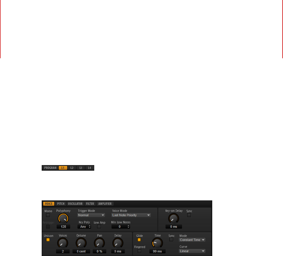
Voice Tab
Mono
Allows you to switch between monophonic and polyphonic playback.
• Activate Mono to switch to monophonic playback. Usually, this allows a
more natural sounding performance for solo instruments.
• Deactivate Mono to play polyphonically with the number of notes specified
by the Polyphony control.
Retrigger
This option is only available in Mono mode. If Retrigger is activated, a note that
was stolen by another note is retriggered if you still hold the stolen note when
you release the new one.
This way, you can play trills by holding one note and quickly and repeatedly
pressing and releasing another note, for example.
Polyphony
Sets the upper limit for the number of notes that you can play if Mono is
deactivated.

Editing Layers
Voice Tab
37
NOTE
If the program has a lower value for polyphony than any of its layers, the
maximum number of notes is determined by the program.
Trigger Mode
Defines the trigger behavior for new notes.
•Normal triggers a new note when the previous note gets stolen. The
sample and the envelope of the new note are triggered from the start.
To minimize discontinuities, use the Fade Out parameter of the zone.
•Resume does not always trigger a new note.
If the new note stays within the same zone, the envelope is retriggered, but
resumes at the level of the stolen note. The pitch of the zone is set to the
new note.
If the new note plays in a different zone, the sample and the envelope of the
new note are triggered from the start.
•Legato does not always trigger a new note.
If the new note stays within the same zone, the envelope keeps running.
The pitch of the zone is set to the new note.
If the new note plays in a different zone, the sample and the envelope of the
new note are triggered from the start.
•Resume Keeps Zone does not trigger a new note upon note stealing. The
envelope resumes at the level of the stolen note and the pitch of the zone is
set to the new note, even if the new note plays in a different zone.
•Legato Keeps Zone does not trigger a new note upon note stealing. The
envelope keeps running and the pitch of the zone is set to the new note,
even if the new note plays in a different zone.
Voice Mode
Determines which notes are stolen during playback and whether new notes are
triggered when the Polyphony setting is exceeded.
•Last Note Priority – New notes have playback priority over the notes that
were played before them.
If you exceed the maximum number of notes, the notes that were played
first are stolen in chronological order (First in/First Out) and the new notes
are triggered.
•First Note Priority – Older notes have playback priority over newer notes.
If you exceed the maximum number of notes while older notes are still
being held, no notes are stolen. New notes are only triggered if a free voice
is available.
•Low Note Priority – Low notes have playback priority over higher notes.
If you exceed the maximum number of notes by playing a lower note than
the ones that are held, the highest note is stolen and the new note is
triggered.
If you exceed the maximum number of notes by playing a higher note than
the ones that are held, no note is stolen and no new note is triggered.

Editing Layers
Voice Tab
38
•High Note Priority – High notes have playback priority over lower notes.
If you exceed the maximum number of notes by playing a higher note
than the ones that are held, the lowest note is stolen and the new note is
triggered.
If you exceed the maximum number of notes by playing a lower note than
the ones that are held, no note is stolen and no new note is triggered.
•Steal Lowest Amplitude – New notes have playback priority over notes with
a low amplitude.
If you exceed the maximum number of notes, the note with the lowest
amplitude is stolen and the newest note is triggered.
•Steal Released Notes – New notes have priority over notes that enter the
release phase.
If you exceed the maximum number of notes, the oldest note that is in its
release phase is stolen and the new note is triggered.
If no note is playing in release and you exceed the maximum number of
notes, the first played notes are stolen in chronological order and the new
notes are triggered.
Key Poly
With this parameter, you can specify an upper limit for the number of notes that
can be played for a key. The notes that were played last have priority. For this
parameter to have an effect, the Mono button must be deactivated.
NOTE
Key Poly is limited by the Polyphony setting.
Low Amp
By default, the oldest note is removed first when notes are stolen due to a Key
Poly limitation. If you want the note with the lowest amplitude to be removed
instead, activate Low Amp.
Min Low Notes
Defines the number of low notes that cannot be stolen, regardless of the Voice
Mode setting.
Make sure that the polyphony of the program is high enough for your specific Min
Low Notes setting and allows to play additional higher notes.
Key On Delay
With this parameter, you can delay the playback of the layer by a specified time or
a note value.
If Sync is deactivated, the delay is specified in milliseconds. If Sync is activated,
the delay is specified in fractions of beats.
To synchronize the delay time to the host tempo, activate the Sync button and
select a note value from the pop-up menu. To change the selected note value to a
triplet, activate the T button.

Editing Layers
Voice Tab
39
Unison
Allows you to trigger multiple voices simultaneously with each note that you play.
If you activate Unison, the following parameters become available:
•Voices determines the number of voices that are triggered simultaneously
(max. 8).
•Detune detunes the pitch of each unison voice in cents. This produces a
fatter sound.
•Pan spreads the unison voices across the stereo panorama. The higher the
value, the broader the stereo image.
•Delay allows you to introduce a small random delay for each unison voice.
With a value of 0 %, all unison voices are triggered at the same time. Values
from 1 % to 100 % add a random delay to each unison voice. The higher the
value, the more random the delay. This is especially useful to avoid comb
filter effects with two or more slightly detuned samples.
Glide
Allows you to bend the pitch between notes that follow each other. You achieve
the best results in Mono mode. If you activate Glide, the following parameters
become available:
•Time specifies the time needed to bend the pitch from one note to the
other.
• Activate Sync to synchronize the delay time to the host tempo. Select a note
value from the pop-up menu. To change the selected note value to a triplet,
activate the T button.
•Mode determines the glide time.
Set this parameter to Constant Time to keep the glide time constant and
independent from the note interval.
Set this parameter to Constant Speed to change the glide time with the
note interval. Larger intervals result in longer glide times.
•Curve allows you to select one of three curve types to define the glide
behavior.
With the Linear curve, the pitch glides at continuous speed from the start
to the end pitch.
With the Exponential curve, the pitch starts gliding at higher speed and
decelerates towards the end pitch. This behavior is similar to the natural
pitch glide produced by a singer.
With the Quantized curve, the pitch glides in semitones from the start to
the end pitch.
•Fingered allows you to glide the pitch only between notes that are played
legato.
NOTE
If you use Cutoff Key Follow, Level Key Follow, and Pan Key Follow, the
corresponding parameters also change with the Glide effect.
Editing Layers
Pitch Tab
40
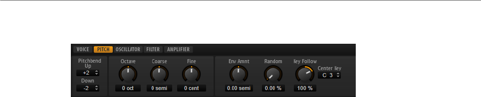
Pitch Tab
Pitchbend Up/Pitchbend Down
Determines the range for the modulation that is applied when you move the
pitchbend wheel.
Octave
Allows you to shift the octave of a layer by ±5 octaves.
Coarse
Allows you to shift the pitch of a layer by ±12 semitones.
Fine
Allows you to detune a layer by ±100 cents.
Pitch Envelope Amount
Determines how much the pitch is affected by the pitch envelope.
Random Pitch
Allows you to randomly offset the pitch with each played note. Higher values
cause stronger variations. At a setting of 100 %, the random offsets can vary from
-6 to +6 semitones.
Pitch Key Follow
Allows you to adjust the pitch modulation by MIDI note number. Set this
parameter to positive values in order to raise the pitch the higher you play. Use
negative values to lower the pitch the higher you play. At a setting of +100 %, the
pitch follows the played note exactly.
Center Key
Specifies the MIDI note that is used as the central position for the Pitch Key
Follow function.
Oscillator Tab
The Oscillator tab offers six sound sources: three main oscillators, the sub oscillator, the
ring modulation, and the noise generator. To create interesting electronic spectra, you can
mix any of these sound sources. The resulting signal is sent to the Filter and Amplifier tabs
for further sound shaping.
The three main oscillators (OSC 1, OSC 2, and OSC 3) offer several wave shapes and
algorithms.
• To activate an oscillator, click its On/Off button.
Editing Layers
Oscillator Tab
41
OSC 1/2/3 Type
The oscillator type defines the basic sound character of the oscillator. This pop-
up menu lists the waveforms (sine, triangle, saw, or square), followed by the
algorithm (PWM, Sync, CM, or XOR). The combination of waveform and algorithm
controls the sound of the oscillator.
The following algorithms are available:
•PWM (pulse width modulation) is only supported by the square waveform.
The Waveform parameter sets the ratio between the high and low value
of the square wave. A setting of 50 % produces a pure square wave. With
settings below or above 50 %, the oscillator produces rectangular waves.
•Sync provides different hard-sync oscillators, where each is a combination
of a master and slave oscillator. The wave shape of the slave oscillator
(sine, triangle, saw, or square) is reset with each full wave cycle of the
master oscillator. This means that a single oscillator can produce a
rich sync-sound without using other oscillators as slave or master. The
Waveform parameter adjusts the pitch of the slave oscillator, producing the
typical sync sound.
•CM (cross modulation) provides a combination of two oscillators where
a master oscillator is modulating the pitch of a slave oscillator (sine,
triangle, saw, or square) at the rate of the audio sample. The Waveform
parameter adjusts the pitch ratio between slave and master oscillator,
resulting in a sound close to frequency modulation.
•XOR (exclusive OR) compares two square waveforms with an XOR
operation. Depending on the outcome of the XOR operation, the waveform
shape of a third oscillator (sine, triangle, saw, or square) is reset. The
Waveform parameter adjusts the pitch ratio of the square oscillators
resulting in a sound close to ring modulation of the third oscillator.
Osc 1/2/3 Waveform
Modifies the sound of the oscillator algorithm. Its effect depends on the selected
oscillator type.
NOTE
• Except for PWM, all algorithms support the sine, triangle, saw, and square
wave shapes. PWM supports only the square wave shape.
• The Waveform parameter for the three main oscillators can be assigned as
modulation destinations in the modulation matrix.
OSC 1/2/3 Octave
Adjusts the pitch in octave steps.

Editing Layers
Oscillator Tab
42
OSC 1/2/3 Coarse
Adjusts the pitch in semitone steps.
OSC 1/2/3 Fine
Adjusts the pitch in cent steps. This allows you to fine-tune the oscillator sound.
OSC 1/2/3 Level
Adjusts the output level of the oscillator.
NOTE
Waveform, pitch, and level of oscillator 1, 2, and 3 can be modulated separately in
the modulation matrix.
Multi-Oscillator Mode
For the three main oscillators, you can activate Multi-Oscillator mode. This allows you to
create a richer sound by producing up to eight oscillators simultaneously.
• To activate Multi-Oscillator mode, activate the MO button.
If Multi-Oscillator mode is activated, you can click the edit button to show the
corresponding parameters.
NOTE
If Multi-Oscillator mode is active for an oscillator, you can modulate the corresponding
parameters in the modulation matrix.
Multi Oscillator Number, Detune, and Spread
Each of the main oscillators offers these multi-oscillator functions. They allow
you to create a richer sound by producing up to eight oscillators simultaneously.
•Number determines the number of oscillators that play back
simultaneously. You can also set fractions of numbers. For example, with
a setting of 2.5, you hear two oscillators at full level and a third one at half
level.
•Detune detunes the oscillators.
•Spread narrows or widens the stereo panorama. With a setting of 0 %, you
create a mono signal, and with 100 %, you create a stereo signal.
Sub Oscillator
The pitch of the sub oscillator is always one octave lower than the overall pitch. The overall
pitch is determined by the Octave setting.
On/Off
Activates/Deactivates the sub oscillator.
Type
The wave shape of the sub oscillator. You can choose between Sine, Triangle,
Saw, Square, Pulse Wide, and Pulse Narrow.
Editing Layers
Filter Tab
43
Level
Adjusts the output level of the sub oscillator.
Ring Modulator
Ring modulation produces sums and differences between the frequencies of two signals.
Ring Modulation Source 1/Ring Modulation Source 2
Determines the sources to be ring modulated. You can select OSC 1 or Sub as
Source 1, and OSC 2 or OSC 3 as Source 2.
NOTE
Make sure that the corresponding oscillators are activated when you select them.
Otherwise, no sound is heard.
Ring Modulation Level
Adjusts the output level of the ring modulation.
Noise Generator
The Noise parameter is used for non-pitched sounds. In addition to standard white and pink
noise, there are also band-pass filtered versions of white and pink noise.
Noise Type
The sound color of the noise. You can choose between standard and band-pass
filtered (BPF) versions of white and pink noise.
Noise Level
Adjusts the output level of the noise generator.
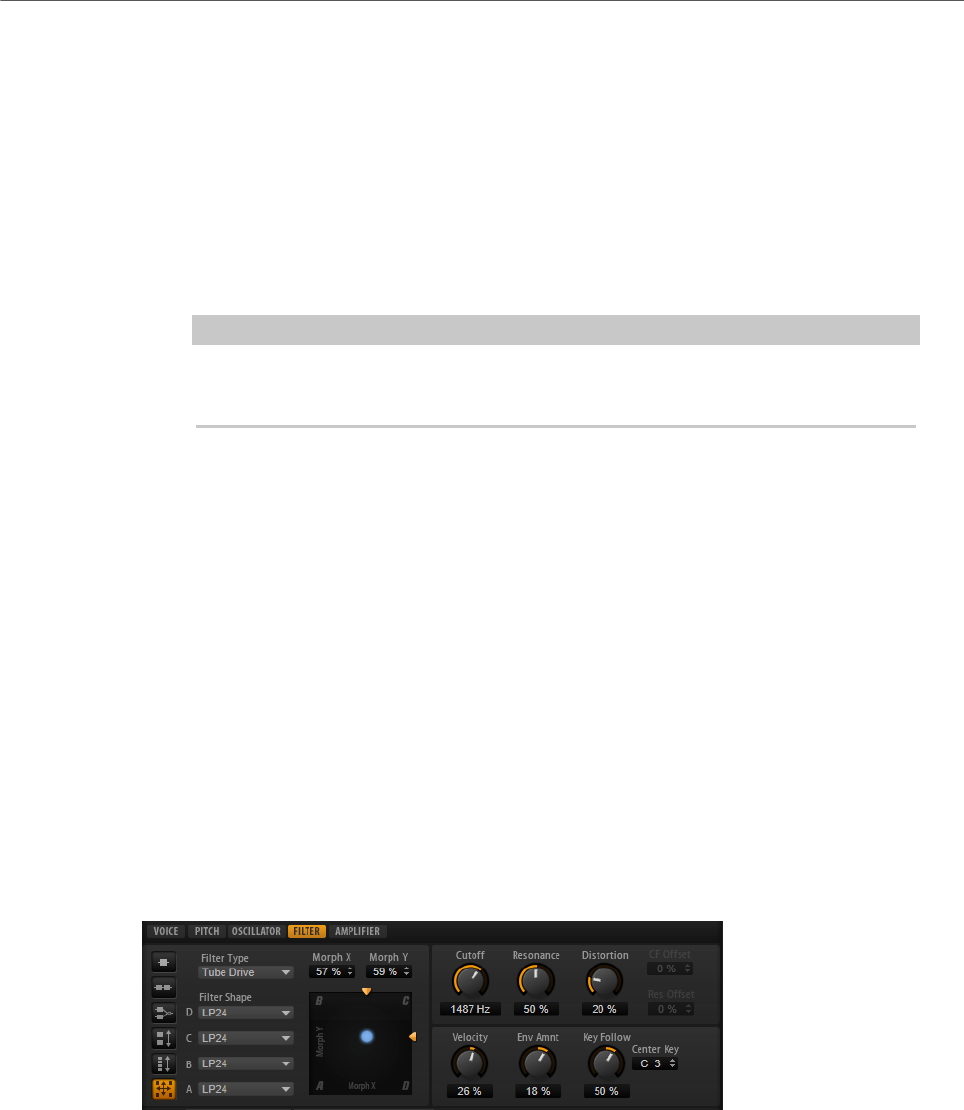
Filter Tab
Filter Mode
The buttons on the left determine the overall filter structure.
•Single Filter uses one filter with one selectable filter shape.
•Dual Filter Serial uses two separate filters connected in series.
You can select the filter shapes for each filter independently. The
parameters Cutoff and Resonance control both filters simultaneously.
However, you can offset these parameters for the second filter with the
parameters CF Offset and Res Offset.

Editing Layers
Filter Tab
44
•Dual Filter Parallel uses two separate filters connected in parallel.
You can select the filter shapes for each filter independently. The
parameters Cutoff and Resonance control both filters simultaneously.
However, you can offset these parameters for the second filter with the
parameters CF Offset and Res Offset.
•Morph 2 morphs between filter shape A and B.
Adjust the morphing with the Morph Y parameter.
•Morph 4 morphs sequentially from filter shape A to D.
Adjust the morphing with the Morph Y parameter.
•Morph XY morphs freely between the filter shapes A, B, C, and D.
Adjust the morphing with the Morph X and Morph Y parameters.
Filter Type
Specifies the basic sound character of the filter.
•Off deactivates the filter section.
•Classic offers 24 filter shapes with resonance.
•Tube Drive adds warm, tube-like distortion. You can set the amount of tube
drive with the Distortion parameter.
•Hard Clip adds bright, transistor-like distortion. You can set the amount of
hard clipping with the Distortion parameter.
•Bit Red (Bit Reduction) adds digital distortion by means of quantization
noise. You can adjust the bit reduction with the Distortion parameter.
•Rate Red adds digital distortion by means of aliasing. You can adjust the
rate reduction with the Distortion parameter.
•Rate Red KF adds digital distortion by means of aliasing. In addition, Key
Follow is used. The rate reduction follows the keyboard, so the higher you
play, the higher the sample rate.
•HALion 3 offers the five legacy filter shapes from HALion3.
•Waldorf offers 13 filter shapes, including two comb filters.
•Eco is a performance-optimized low-pass filter without Resonance or
Distortion parameters. It allows you to adapt the brilliance of samples for
different velocity layers of the same key, for example.
NOTE
Filters without distortion use less processing power.
Filter Shape
• LP24, 18, 12, and 6 are low-pass filters with 24, 18, 12, and 6 dB/oct.
Frequencies above the cutoff are attenuated.
• BP12 and BP24 are band-pass filters with 12 and 24 dB/oct. Frequencies
below and above the cutoff are attenuated.
• HP6+LP18 and HP6+LP12 are combinations of a high-pass filter with 6 dB/
oct and a low-pass filter with 18 and 12 dB/oct, respectively (asymmetric
band-pass filter). Frequencies below and above the cutoff are attenuated.
Attenuation is more pronounced for the frequencies above the cutoff.

Editing Layers
Filter Tab
45
• HP12+LP6 and HP18+LP6 are combinations of a high-pass filter with 12
and 18 dB/oct and a low-pass filter with 6 dB/oct (asymmetric band-pass
filter). Frequencies below and above the cutoff are attenuated. Attenuation
is more pronounced for the frequencies below the cutoff.
• HP24, 18, 12, and 6 are high-pass filters with 24, 18, 12, and 6 dB/oct.
Frequencies below the cutoff are attenuated.
• BR12 and BR24 are band-reject filters with 12 and 24 dB/oct. Frequencies
around the cutoff are attenuated.
• BR12+LP6 and BR12+LP12 are combinations of a band-reject filter with 12
dB/oct and a low-pass filter with 6 and 12 dB/oct, respectively. Frequencies
around and above the cutoff are attenuated.
• BP12+BR12 is a band-pass filter with 12 dB/oct plus a band-reject filter
with 12 dB/oct. Frequencies below, above, and around the cutoff are
attenuated.
• HP6+BR12 and HP12+BR12 are combinations of a high-pass filter with 6
and 12 dB/oct and a band-reject filter with 12 dB/oct. Frequencies below
and around the cutoff are attenuated.
• AP is an all-pass filter with 18 dB/oct. Frequencies around the cutoff are
attenuated.
• AP+LP6 is an all-pass filter with 18 dB/oct plus a low-pass filter with 6 dB/
oct. Frequencies around and above the cutoff are attenuated.
• HP6+AP is a high-pass filter with 6 dB/oct plus an all-pass filter with 18
dB/oct. Frequencies around and below the cutoff are attenuated.
X/Y Control
Allows you to adjust two parameters simultaneously.
• For the filter types Single, Dual Serial, and Dual Parallel, the X/Y control
adjusts the cutoff frequency on the horizontal axis and the resonance on
the vertical axis.
• For the filter types Morph 2 and Morph 4, the X/Y control adjusts the
morphing between the filter shapes on the vertical axis. The horizontal axis
adjusts the cutoff frequency.
• For Morph XY, the X/Y control adjusts the morphing between the filter
shapes AD and BC on the horizontal axis, and AB and DC on the vertical
axis.
Cutoff
Controls the cutoff frequency of the filter.
Resonance
Emphasizes the frequencies around the cutoff. At higher settings, the filter self-
oscillates, which results in a ringing tone.
Distortion
Adds distortion to the signal. The effect depends largely on the selected filter
type. At higher settings, it creates a very intense distortion effect.
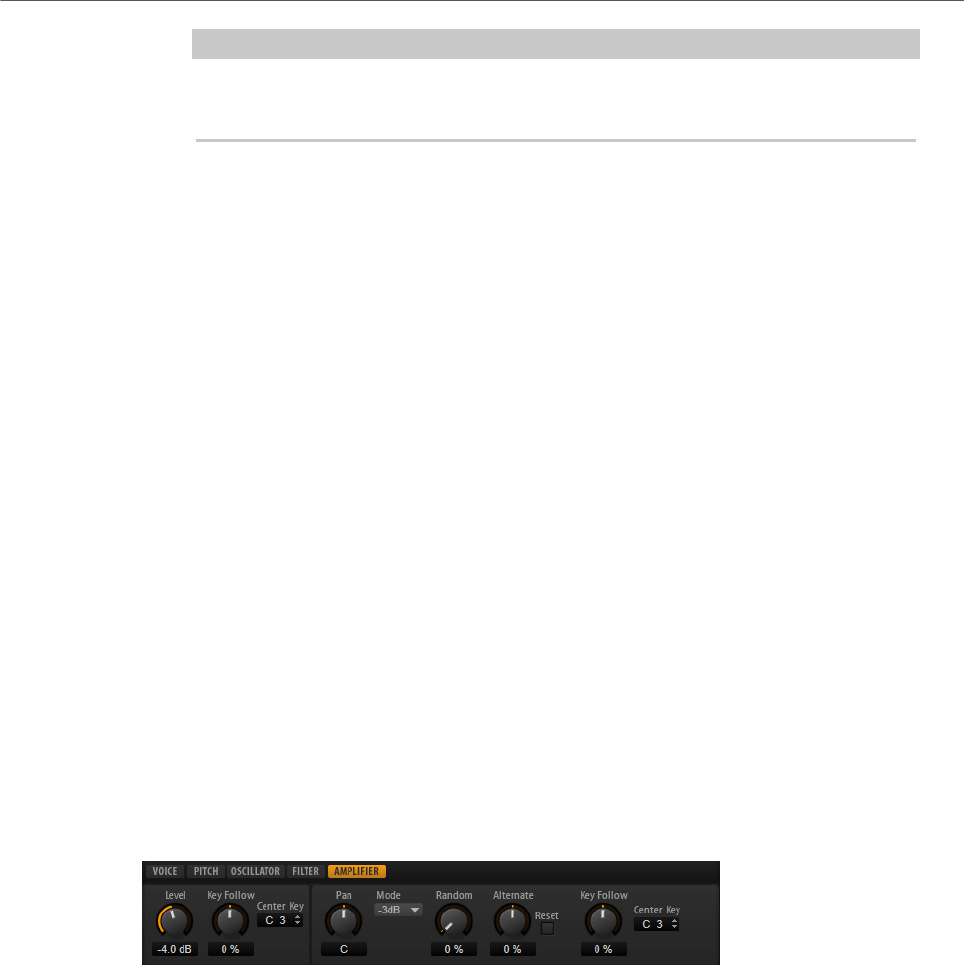
Editing Layers
Amplifier Tab
46
NOTE
This parameter is only available for the filter types Tube Drive, Hard Clip, Bit Red,
Rate Red, and Rate Red KF.
CF Offset
For the dual filters, this parameter allows you to offset the cutoff frequency of the
second filter, that is, of filter shape B.
Res Offset
For the dual filters, this parameter allows you to offset the resonance of the
second filter, that is, of filter shape B.
Cutoff Velocity
Controls the cutoff modulation from velocity.
Envelope Amount
Controls the cutoff modulation from the filter envelope.
Cutoff Key Follow
Adjusts the cutoff modulation using the note number. Increase this parameter
to raise the cutoff with higher notes. At 100 %, the cutoff follows the played pitch
exactly.
Center Key
Specifies the MIDI note that is used as the central position for the Key Follow
function.
Amplifier Tab
Level
Controls the overall volume of the sound.
Level Key Follow
Allows you to control the volume depending on the note pitch. Positive values
mean that the volume is higher the higher the notes you play. With negative
values, the volume decreases the higher the notes you play.
Center Key
Specifies the MIDI note that is used as the center position for Level Key Follow.
Pan
Determines the position of the sound in the stereo panorama. At a setting of -100
%, the sound is panned hard left, and at +100 %, it is panned hard right.

Editing Layers
Amplifier Tab
47
Mode
With this option you can specify how the loudness changes across the stereo
panorama.
• If this parameter is set to 0 dB, it works like a balance control.
Setting the pan control towards the left fades out the right channel and vice
versa. At the center position, the loudness is not cut.
• If this parameter is set to -3 dB, the option uses the cosine/sine pan law.
The loudness is cut by -3 dB at the center position, but the energy is
preserved when moving the source signal across the stereo panorama.
The -3 dB option sounds more natural. The transition from hard left to hard
right sounds much smoother than with the 0 dB or the -6 dB setting.
• If this parameter is set to -6 dB, this option uses the linear pan law.
The loudness is cut by -6 dB at the center position, and the energy is not
preserved when moving the source signal across the stereo panorama. The
-6 dB option sounds more synthetic. The transition from hard left to hard
right sounds more abrupt than with the -3 dB setting.
• If this parameter is set to Off, no panning is applied.
Random Pan
Allows you to offset the pan position randomly with each played note. Higher
values cause stronger variations. At a setting of 100 %, the random offsets can
vary from fully left to fully right.
Alternate Pan
Allows you to alternate the pan position each time that you play a note. To start
panning on the left, use negative values. Use positive values to begin on the right.
At a setting of +100 %, the first note plays hard right, the second note hard left,
and so on.
Reset
The initial pan position is set once when HALion Sonic is loaded. After that, each
note that you play is counted to determine the next pan position. To reset this
counter, click the Reset button.
Pan Key Follow
Allows you to adjust the pan modulation via the MIDI note number. Set this
parameter to positive values to offset the pan position towards the right for notes
above, and towards the left for notes below the center key. Use negative values to
offset the pan position towards the left for notes above, and towards the right for
notes below the center key.
At the maximum setting of +200 %, the pan position moves from hard left to hard
right within two octaves: Fully left is reached one octave below and fully right is
reached one octave above the center key.
Center Key
Specifies the MIDI note that is used as the center position for Pan Key Follow.
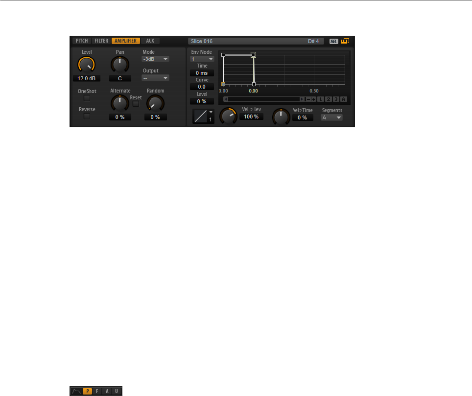
Editing Layers
Envelopes
48
Additional Parameters for Drum and Loop Layers
One Shot
If this button is activated, any MIDI note-off messages are ignored. The release
segments of the envelopes is not played. Instead, the envelopes play until the
sustain is reached and remain on that level for as long as the sample plays back.
Any loop settings of the sample are ignored.
Reverse
If this button is activated, the sample is played in reverse. Any loop settings the
sample may contain are ignored.
Envelopes
On the Edit page, you can edit the pitch (P), filter (F), amp (A), and user (U) envelopes. Each of
these is a multi-segment envelope with up to 128 nodes. The nodes specify the overall shape
of the envelope. The amp, filter, and pitch envelopes are pre-assigned to the amplitude, the
filter cutoff frequency, and the pitch of the layer. The user envelope is freely assignable.
All envelopes can be used as sources in the modulation matrix.
• Click P to display the parameters of the pitch envelope.
The pitch envelope modulates the pitch over time. The pitch envelope is bipolar, which
means it allows for negative and positive values to bend the pitch.
• Click F to display the parameters of the filter envelope.
The filter envelope controls the cutoff frequency to shape the harmonic content over
time.
• Click A to display the parameters of the amplifier envelope.
The amplifier envelope shapes the volume over time.
• Click U to display the parameters of the freely assignable user envelope.
The user envelope is bipolar, which means it allows for negative and positive values,
for example, to modulate the pan from left to right.
Mode
Determines how the envelope is played back when it is triggered.
• Select Sustain to play the envelope from the first node to the sustain node.
The sustain level is held for as long as you play the note. When you release
the note, the envelope continues with the stages following the sustain. This
mode is ideal for looped samples.

Editing Layers
Envelopes
49
• Select Loop to play back the envelope from the first node to the loop nodes.
Then, the loop is repeated for as long as the key is held. When you release
the note, the envelope continues playing the stages that follow the sustain.
This mode is ideal for adding motion to the sustain of the envelope.
• Select One Shot to play the envelope from the first to the last node, even if
you release the key. The envelope has no sustain stage. This mode is ideal
for drum samples.
• Select Sample Loop to preserve the natural attack of the sample. The
decay of the envelope does not start until the sample has reached the
sample loop start.
If you set the second node to the maximum level and use the following
nodes to shape the decay during the loop phase of the sample, the
envelope only affects the loop phase. The attack of the envelope is still
executed.
NOTE
Sample Loop mode is only available for sample layers.
Sync
Allows you to synchronize the envelopes to the tempo of your host application.
Snap
You can select a second envelope to be displayed in the background of the edited
envelope. If Snap is activated and you change the position of nodes, they snap to
the nodes of the envelope that is shown in the background.
• To specify the envelope for the background, open the pop-up menu to the
right of the Snap button and select an envelope from the list.
Fill
Allows you to add multiple envelope nodes after the selected nodes.
Fixed
• If Fixed is activated and you move selected nodes on the time axis, only the
selected nodes are moved.
• If Fixed is deactivated, all nodes that follow the edited nodes are also
moved.
Env Node
Displays the focused envelope node.
Time
Specifies the period of time between two nodes. Depending on the Sync mode,
the Time parameter is displayed in milliseconds and seconds, or in fractions of
beats.
Curve
Allows you to adjust the curvature of the envelope curve between two nodes from
linear to logarithmic or exponential behavior.

Editing Layers
Envelopes
50
Level
Specifies the amplitude of the envelope at the position set by the Time
parameter.
Level Velocity Curve
You can select the curve type to specify how the incoming velocity translates to
the level of the envelope. The characteristic of each curve is displayed by a small
icon.
Level Velocity (Vel>Lev)
Determines how the velocity affects the level of the envelope.
The level of the envelope depends on two factors: the setting of this parameter
and how hard you hit a key. Positive values increase the level of the envelope
the harder you hit a key. Negative values decrease the level of the envelope the
harder you hit a key.
Time Velocity (Vel>Time)
Adjusts the influence of velocity on the phases of the envelope. Positive values
decrease the length of the phases for higher velocity values. Negative values
increase the length of the phases for higher velocity values.
Segments
Here, you can select which phases of the envelope are affected by the Time
Velocity parameter.
•Attack – The velocity affects the attack only.
•Attack + Decay – The velocity affects all phases until the sustain.
•Decay – The velocity affects all phases until the sustain but without the
attack.
•Attack + Release – The velocity affects the attack and the release phases.
•All – The velocity affects all phases.
Time Key Follow, Center Key, and KeyF Rel (Key Follow Release)
With the Time Key Follow and KeyF Rel parameters, you can scale the envelope
phases across the keyboard.
•Time Key Follow scales all times before the sustain node.
•KeyF Rel scales all times after the sustain node, that is, the release phase
of the envelope.
The value that you specify for Center Key is used as the central position for the
Time Key Follow and KeyF Rel functions.
The envelope phases depend on the keyboard range in which the note is played
and on the corresponding Time Key Follow setting:
• Positive values decrease the phase lengths for notes above and increase
the phase lengths for notes below the set Center Key, that is, the envelope
becomes faster the higher the note you play.

Editing Layers
Envelopes
51
• Negative values increase the phase lengths for notes above and decrease
the phase lengths for notes below the Center Key, that is, the envelope
becomes slower the higher the note you play.
Zooming
The vertical axis of the graphical envelope editor displays the level. The horizontal axis
displays the time.
• To zoom in or out, click the + or - buttons to the right of the scrollbar below the
graphical editor.
• To zoom in or out at the current position, click in the timeline and drag up or down.
• To toggle between full zoom and the previous zoom setting, click the A button to the
right of the horizontal zoom slider.
• To zoom to a specific region, hold Alt, click and drag the mouse over the region.
Zoom Snapshots
Zoom snapshots save the zoom factor and scroll position of the editor. These are restored
when you load the snapshot.
To the right of the scrollbar, you can find three numbered buttons that allow you to save and
load zoom snapshots.
• To save the current state of the editor as snapshot, Shift-click one of the numbered
buttons to the right of the scrollbar.
• To load a zoom snapshot, click the corresponding button. The button color changes if a
snapshot is active.
NOTE
If you perform any manual zooming or scrolling, the zoom snapshot is deactivated.
Selecting Nodes
• To select a node, click on it in the graphical editor.
The focused node is indicated by a frame. The value fields to the left of the graphical
envelope editor display the parameters of the focused node.
• If multiple nodes are selected, you can use the Env Node pop-up menu to set the focus
to a different node without losing the current selection.
• To add a node to a selection, Shift-click the node. Selected nodes are edited together.
• You can select multiple nodes by drawing a rectangle around the nodes with the
mouse.
• If the graphical editor has the focus, you can select the next or the previous node with
the left and right arrow keys.

Editing Layers
Envelopes
52
Adjusting the Time Parameter
The Time parameter specifies the period of time between two nodes. Depending on the Sync
mode, the Time parameter is displayed in milliseconds and seconds, or in fractions of beats.
• To set the Time parameter, select the nodes that you want to adjust and enter a value
in the Time field.
• You can also adjust the Time parameter in the graphical envelope editor, by dragging
the nodes left or right, to decrease or to increase the time span.
For a higher resolution, hold Shift while moving the nodes.
To limit the movement to the time axis, that is, to change only the horizontal position of
a node, hold down Ctrl/Cmd while dragging.
Adjusting the Level Parameter
The Level parameter specifies the amplitude of the envelope at the position set by the Time
parameter.
• To set the Level parameter, select the nodes that you want to adjust and enter a value
in the Level field.
• You can also adjust the Level parameter in the graphical envelope editor by dragging
the selected nodes up or down, to decrease or increase the levels.
For a higher resolution, hold Shift while moving the nodes.
To limit the movement to the level axis, that is, to change only the vertical position of a
node, hold down Alt while dragging.
Adjusting the Curve Parameter
The Curve parameter allows you to adjust the curvature of the envelope curve between two
nodes from linear to logarithmic or exponential behavior.
• To set the Curve parameter, select the nodes that you want to adjust and enter a value
in the Curve field. Positive curve values change the curvature towards logarithmic and
negative values towards exponential behavior.
• You can also adjust the Curve parameter in the graphical envelope editor by dragging
the curve between two nodes.
Ctrl/Cmd-click a curve to reset it to linear.
Adding and Removing Nodes
• To add a node, double-click at the position where you want to add the node.
• To remove a node, double-click it.
• To delete several selected nodes, press Delete.
NOTE
• You cannot remove the first, the last, or the sustain node.
• All nodes added after the sustain node always affect the release phase of the envelope.

Editing Layers
Envelopes
53
Adding Nodes Using the Fill Function
The Fill function allows you to add multiple envelope nodes after the selected nodes.
PROCEDURE
1. On the pop-up menu to the right of the Fill button, select the number of nodes that you
want to add.
2. In the graphical envelope editor, select the node after which you want to add nodes.
If several nodes are selected, the new nodes are inserted after the last selected node.
If Fixed is deactivated, the added nodes are placed with the interval specified by the
Time parameter of the selected node. If multiple nodes are selected, the interval is
specified by the focused node.
By activating Sync, you can specify the interval with the Sync note value. For example,
if 1/4 is selected, new nodes are added at exact quarter note intervals.
If Fixed is activated, the added nodes fill the space between the last selected node and
the following one.
3. Click the Fill button.
Using Sync
You can synchronize the envelopes to the tempo of your host application. This allows you to
set envelope times that relate to musical time intervals, regardless of any tempo changes.
PROCEDURE
1. Click Sync to activate sync mode for the envelope.
Sync mode is active if the button is highlighted. A grid spaced in fractions of beats is
displayed in the graphical envelope editor.
2. On the pop-up menu located to the right of the Sync button, select a note value.
This sets the resolution of the grid.
NOTE
The Time field of a node displays times in fractions of beats. The fraction is always
reduced to the smallest possible value. 2/16 is displayed as 1/8, for example.
3. To use triplet note values, activate the T button.
NOTE
•Envelope nodes that do not exactly match a note value display the closest note
value.
•Nodes that exactly match a note value are indicated by a red dot inside the
handle of the node. This is useful if you switch the grid between triplets and
normal note values, for example. The triplet nodes still indicate that they match
a note value, even if the grid shows normal note values.
You can also enter note values and triplets manually in the value field.
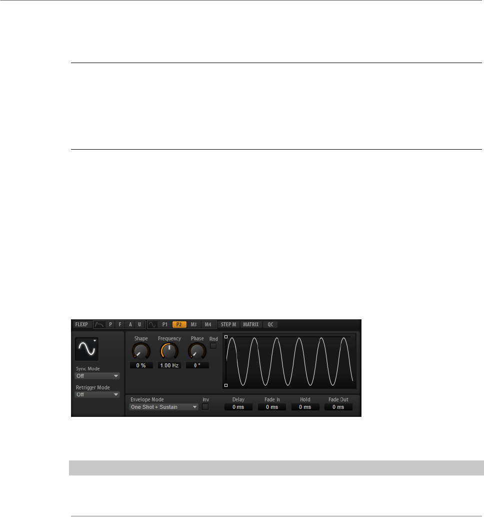
Editing Layers
LFOs
54
Setting Up the Loop
You can set up the envelope to repeat its playback between the selected nodes.
PROCEDURE
1. Set the envelope mode to Loop.
2. The loop is indicated by the green region in the graphical envelope editor. Specify the
loop start and end by dragging the borders of the region.
The loop region can only be set up in the decay phase of the envelope.
LFOs
HALion Sonic offers two polyphonic and two monophonic LFOs. Polyphonic means the LFOs
are calculated per voice, allowing for independent modulations with each triggered note. You
can use this to create a richer sound, for example, with an independent pitch modulation per
note. Monophonic means the LFOs are calculated only once per layer. The same modulation
is sent to all voices simultaneously. The LFOs can be assigned freely in the modulation
matrix.
• Click P1 or P2 to show the settings for the corresponding polyphonic LFO.
• Click M1 or M2 to show the settings for the corresponding monophonic LFO.
You can adjust the times of the envelope in the graphical editor by dragging nodes left or
right.
NOTE
How many nodes are available in the graphical editor depends on the selected Envelope
Mode.
• The first node adjusts the Delay time.
• The second node adjusts the Fade In time.
• The third node adjusts the Hold time.
• The fourth node adjusts the Fade Out time.
Parameters for Monophonic and Polyphonic LFOs
LFO Waveform and Shape
•Sine produces smooth modulation, suitable for vibrato or tremolo. Shape
adds additional harmonics to the waveform.
•Triangle is similar to Sine. Shape continuously changes the triangle
waveform to a trapezoid.

Editing Layers
LFOs
55
•Saw produces a ramp cycle. Shape continuously changes the waveform
from ramp down to triangle to ramp up.
•Pulse produces stepped modulation, where the modulation switches
abruptly between two values. Shape continuously changes the ratio
between the high and low state of the waveform. If Shape is set to 50 %, a
square wave is produced.
•Ramp is similar to the Saw waveform. Shape increasingly puts silence
before the sawtooth ramp up begins.
•Log produces a logarithmic modulation. Shape continuously changes the
logarithmic curvature from negative to positive.
•S & H 1 produces randomly stepped modulation, where each step is
different. Shape puts ramps between the steps and changes the S & H into
a smooth random signal when fully turned right.
•S & H 2 is similar to S & H 1. The steps alternate between random high and
low values. Shape puts ramps between the steps and changes the S & H
into a smooth random signal when fully turned right.
Sync Mode
The Sync Mode is used to match the LFO to the tempo of the host application.
• Select Off to adjust the speed of the modulation in Hertz.
• Select Tempo + Retrig to adjust the speed of the modulation in fractions of
beats. You can also set dotted and triplet note values. The restart behavior
of the LFO depends on the Retrigger Mode.
• Select Tempo + Beat to adjust the speed of the modulation in fractions of
beats. You can also set dotted and triplet note values. The LFO restarts
with the transport of the host and lines up to the beats of the song. The
Retrigger Mode setting is not taken into account.
NOTE
The behavior of the Frequency parameter changes with the selected option.
Retrigger Mode (Monophonic LFOs)
Determines whether the LFO is restarted when a note is triggered. If this is set
to First Note or Each Note, the waveform starts at the position specified by the
Phase parameter.
• If this is set to Off, the LFO runs freely.
• If this is set to First Note, the LFO restarts when a note is triggered and no
other notes are held.
• If this is set to Each Note, the LFO restarts each time a note is triggered.
Frequency
Controls the frequency of the modulation, that is, the speed of the LFO.
Phase
Sets the initial phase of the waveform when the LFO is retriggered.

Editing Layers
LFOs
56
Rnd (Random Phase)
If this button is activated, each note starts with a randomized start phase.
NOTE
The Phase control cannot be used if Rnd is activated.
Additional Parameters for Polyphonic LFOs
Retrigger Mode
Determines whether the LFO is restarted when a note is triggered. The waveform
restarts at the position set with the Phase parameter.
The polyphonic LFOs can switch between On and Off.
• If this parameter is set to Off, the LFO runs freely.
• If this parameter is set to On, the LFO starts with each triggered note.
Envelope Mode
Allows you to specify how the LFO envelope reacts to your playing on the
keyboard. The One Shot modes do not react to note-off events.
• Select One Shot to play the envelope from start to end in the time specified
by the Delay, Fade In, Hold, and Fade Out parameters.
•One Shot + Sustain is similar to One Shot. The Delay and Fade In
parameters are always applied when you play a note. The Hold and Fade
Out parameters are not available.
• If Hold + Fade Out is selected and you play a note, the Delay and Fade In
parameters are applied. The envelope fades out after the time specified by
the Hold parameter or when a key is released. Releasing a key during the
fade in starts the fade out from the current level.
• If Sustain + Fade Out is selected and you play a note, the Delay and Fade In
parameters are applied. The Hold parameter is not available. The fade out
is applied when releasing the key. Releasing a key during the fade in starts
the fade out from the current level.
• If Sustain is selected and you play a note, the Delay and Fade In
parameters are applied. The Hold and Fade Out parameters are not
available. Releasing a key during the fade in sustains the current level. This
prevents a change in modulation when a key is released.
Inv (Invert Envelope)
If this parameter is activated, the behavior of the LFO envelope is inverted, that
is, the LFO modulation starts at its maximum level and decreases to zero in the
time specified by the Fade In parameter. After the Hold time has elapsed, or
when the key is released, the modulation increases to its maximum level in the
time specified by the Fade Out parameter.
Delay
Determines the delay time between the moment you play a note and the moment
the LFO comes into effect.
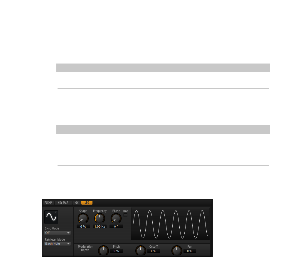
Editing Layers
LFOs
57
Fade In
Determines how long the LFO takes to fade in after the note was triggered and
the Delay time has elapsed.
Hold
Determines the amount of time the LFO is running before the fade out begins.
NOTE
Hold is only available for the envelope modes One Shot and Hold + Fade Out.
Fade Out
Determines how long the LFO takes to fade out after the hold time has elapsed or
a note has been released.
NOTE
To deactivate the fade out, use the envelope modes One Shot + Sustain or
Sustain. This ensures that the modulation does not change when a note is
released.
LFO Tab for Loop Layers
Loop layers offer a monophonic LFO with adjustable depth for Pitch, Cutoff, and Pan.
For loop layers, the following additional parameters are available:
Pitch
Adjusts how much the LFO affects the pitch of the slices.
Cutoff
Adjusts how much the LFO affects the cutoff of the slices.
Pan
Adjusts how much the LFO affects the pan of the slices.
When using the LFO of loop layers, the following applies:
• The modulation of Pitch, Cutoff, and Pan goes to all slices simultaneously. The
modulation depth cannot be set separately per slice.
• The filter must be activated to hear the modulation of the Cutoff.
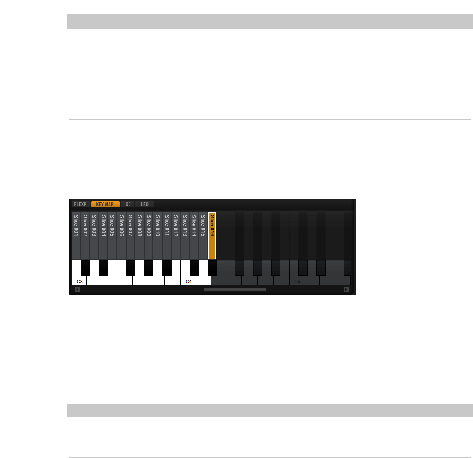
Editing Layers
Using the Keymap
58
NOTE
With a Resonance of 100 %, you might hear clicks because the slice ends abruptly, but the
filter still produces a sound from self-oscillation. In this case, go to the corresponding
FlexPhraser and reduce the Gate Scale until the clicks are gone. In addition, you can adjust
the amplifier envelope of the slices, for example, to increase the release of the envelopes.
Apart from the Pitch, Cutoff, and Pan parameters, all other parameters correspond to the
parameters on the LFO pages for sample and synth layers.
Using the Keymap
In the key map at the bottom of the editor, you see the drum instruments or loop slices that
are part of the drum or loop layer, and how they are mapped across the keyboard.
•Keys with a drum instrument or loop slice assigned display in normal white and black.
•The names of the drum instruments or loop slices are displayed vertically above the
keys.
•Keys with nothing assigned are deactivated and displayed in gray.
•For loop layers, the pitched part of the keyboard is displayed in orange.
•Clicking a key plays and selects the corresponding drum instrument or loop slice.
NOTE
The key map is used for indication and selection only. The mapping of the drum instruments
and loop slices cannot be changed.
To edit a drum instrument or loop slice, you must select it first. You can select drum
instruments or loop slices by clicking the corresponding keys on the key map or by using
your MIDI keyboard.
To select a drum instrument or loop slice with your MIDI keyboard, activate Select Zones via
MIDI in the top section of the layer editor and press the key that plays the drum instrument
or loop slice that you want to adjust.
You can edit the selected drum instrument or loop slice using the parameters on the Pitch,
Filter, Amplifier, and AUX tabs.
AUX Tab
Each drum instrument and loop slice has individual send levels that feed the four global AUX
FX busses. This allows you to add more reverb to the snare drum and less effect to the bass
drum, for example.
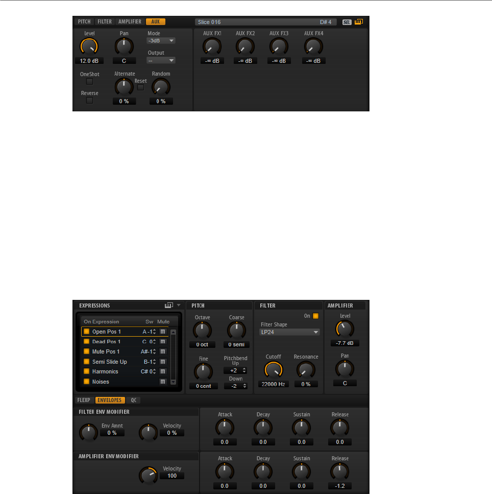
Editing Layers
Expression Controls for Instrument Layers
59
AUX FX1 – 4
These dials adjust the send levels for the four global AUX FX busses for each
drum instrument or loop slice separately.
Expression Controls for Instrument Layers
Instrument layers contain expressions. Typically, an expression is a particular playing style of
the instrument. In some cases, it can also be a part of the sound that can be turned on or off,
for example, to add realism or to maximize the performance.
The list of expressions is displayed on the left and on the right and in the lower section, you
can find the pitch, filter and amplifier settings of the selected expression.
• To load an expression, activate its On button.
• To mute an expression, activate its Mute button.
• If you want the editor to follow incoming MIDI key switches or MIDI controller values,
activate Select Expression via MIDI.
The parameters on the Pitch, Filter, and Amplifier sections are the same as on the
corresponding tabs for the other layer types.
Filter Env Modifier Section
This section offers parameters to modify the filter envelope of the expression.
Envelope Amount
Controls the cutoff modulation from the filter envelope.

Editing Layers
Expression Controls for Instrument Layers
60
Velocity
Determines how the velocity affects the level of the filter envelope.
The level of the envelope depends on two factors: the setting of this parameter
and how hard you hit a key. Positive values increase the level of the envelope
the harder you hit a key. Negative values decrease the level of the envelope the
harder you hit a key.
Attack
Controls the attack time of the filter envelope.
Decay
Controls the decay time of the filter envelope.
Sustain
Controls the sustain level of the filter envelope.
Release
Controls the release time of the filter envelope.
Amplifier Env Modifier Section
This section offers parameters to modify the amplifier envelope of the expression.
Velocity
Use this parameter to adjust how velocity affects the level of the amplifier
envelope.
The level of the envelope depends on two factors: the setting of this parameter
and how hard you hit a key. Positive values increase the level of the envelope
the harder you hit a key. Negative values decrease the level of the envelope the
harder you hit a key.
Attack
Controls the attack time of the amplifier envelope.
Decay
Controls the decay time of the amplifier envelope.
Sustain
Controls the sustain level of the amplifier envelope.
Release
Controls the release time of the amplifier envelope.
RELATED LINKS
Pitch Tab on page 40
Filter Tab on page 43
Amplifier Tab on page 46
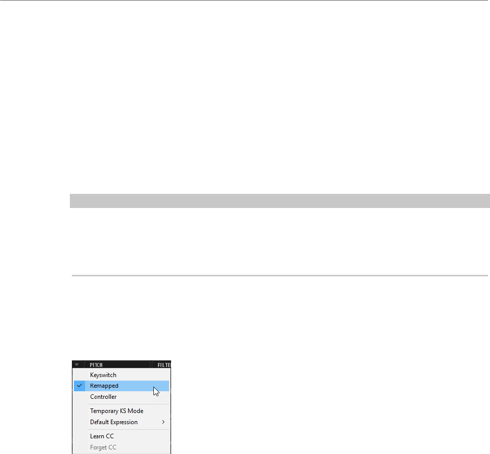
Editing Layers
Insert Effects
61
Expression Maps
For more realistic performances, many instrument layers use key switches to switch
between different expressions, that is, between different articulations and playing styles of
the same instrument. These key switches are set to low keys to maximize the playable range
and they cannot be changed internally to ensure that performances played by FlexPhrasers
always sound the same.
However, in some cases you need to shift the key switches into the playable keyboard range
to get access to them. You may also want to select the expression using a MIDI controller.
You can use so-called expression maps to customize the internal setting.
•To specify the expressions that you want to use in your expression map, activate them
in the expressions list.
NOTE
Some instrument layers consist of multiple expressions that are not switchable via a key
switch. For example, instrument noises typically do not have a key switch assigned. In this
case, you can select the individual expressions and edit them, but you cannot apply any key
switch functionality.
Expression Map Options Menu
You can define whether you want to use the internal key switches, remap them to other keys,
or use a MIDI controller by selecting a mode from the pop-up menu above the expression
list.
• Select Keyswitch to use the internal key switches to switch to an expression.
• Select Remapped if you want to remap the original key switches to other keys.
• Select Controller to use a MIDI controller to remotely control the internal key switches.
To assign a MIDI controller, open the menu, select Learn CC, and use the controller on
your MIDI hardware.
• If you activate Temporary KS Mode, expressions other than the default expression are
only active for as long as the corresponding key switch is held. This allows you to enter
notes with other expressions by pressing a key switch temporarily.
•Default Expression sets the default expression for Temporary KS Mode. This is also
the expression that is active after loading the program or layer.
Insert Effects
The Inserts tab offers you up to four insert effects for each of the layers and for the program
itself. The insert effects you assign to a layer affect only that layer. The insert effects you
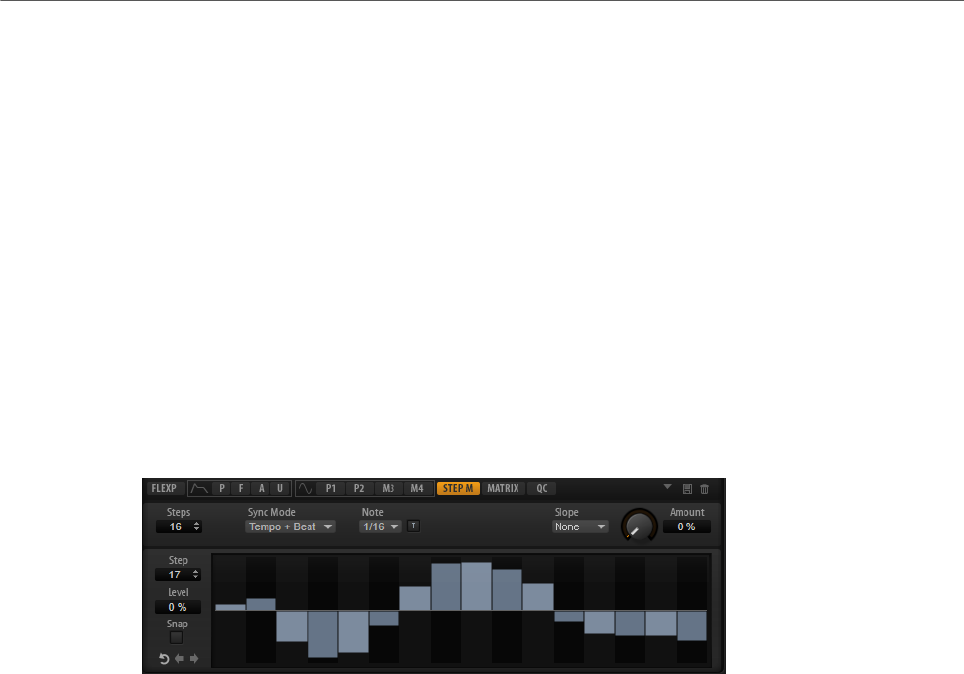
Editing Layers
Step Modulator
62
assign to the program affect all layers. Typically, you assign effects like EQ or distortion to
separate layers, but effects like delay or reverb to the entire program.
Each layer and the program have four slots for assigning insert effects. The handling is the
same for all slots and corresponds to the global effect handling.
To the right of the insert slots, you find faders for adjusting the output levels of the program
and layers.
RELATED LINKS
Using the Insert Effect Slots on page 107
Step Modulator
Synth and sample layers feature a polyphonic step modulator for creating rhythmic control
sequences.
The step modulator can be freely assigned in the modulation matrix.
Steps
Sets the number of steps in the sequence. The maximum number of steps is 32.
Sync Mode
• If Off is selected, you can adjust the speed at which the sequence repeats.
Whether the sequence restarts when you play a note depends on the
Retrigger mode.
• If Tempo + Retrig is selected, you can adjust the length of the steps in
fractions of beats. The speed of the modulation depends on the number of
steps, the note value, and the tempo you set in your host application. To use
triplet note values, activate Triplet.
Whether the sequence restarts when you play a note depends on the
selected Retrigger Mode.
• If Tempo + Beat is selected, you can adjust the length of the steps in
fractions of beats. The speed of the modulation depends on the number of
steps, the note value, and the tempo you set in your host application. To use
triplet note values, activate Triplet.
The sequence restarts with the transport of the host application and lines
up to the beats of the project. The Retrigger Mode is not taken into account.
Frequency
If Sync Mode is set to Off, this controls the speed at which the sequence is
repeated.

Editing Layers
Step Modulator
63
Note
If Sync Mode is set to one of the Tempo settings, this adjusts the length of the
steps in fractions of beats. You can also select triplet values.
Triplet
Activate this button to use triplet note values.
Retrigger Mode
Determines whether the sequence restarts when you play a note. This parameter
is only available if Sync Mode is set to Off or Tempo + Retrig.
• If this parameter is set to Off, the sequence is not restarted. Instead, it
resumes playback at the position at which you released the key.
• If this parameter is set to First Note, the sequence restarts when a note is
triggered and no other notes are held.
• If this parameter is set to Each Note, the sequence restarts each time a
note is triggered.
Slope
Determines whether the step modulator jumps from step to step or creates
ramps between the steps.
•No Slope produces hard steps.
•Slope on Rising Edges creates ramps only for rising edges.
•Slope on Falling Edges creates ramps only for falling edges.
•Slope on All Edges creates ramps for all edges.
Amount
If Slope is set to Rising, Falling, or All, this parameter determines the time of the
ramp between two steps. The higher the setting, the smoother the transitions
between steps.
Step
Allows you to select a specific step.
Level
Shows the level of the selected step.
Snap
If Snap is activated, the level of each step can only be adjusted in steps of 1/12th.
Shift Phrase Right/Shift Phrase Left
These commands shift all the steps to the right/left. If you shift the rhythm of the
phrase to the left, the first step is moved to the end. If you shift the phrase to the
right, the last step is moved to the beginning.
Reverse Phrase
Reverses the phrase, that is, inverts the order of all steps.
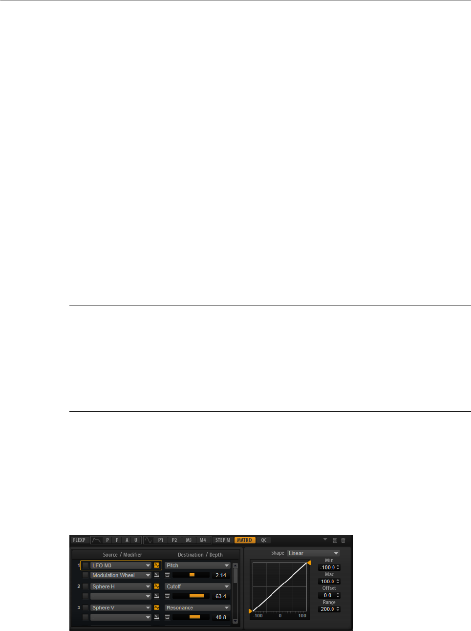
Editing Layers
Modulation Matrix
64
Editing Steps
•To set the level of a step, click at the corresponding position in the graphical editor.
•To change the value of a step, drag the step up or down or enter a new value in the
Level value field.
•To reset the level of a step to 0 %, Ctrl/Cmd-click the step.
•To reset all steps, hold Shift-Ctrl/Cmd and click in the graphical editor.
•To adjust all steps at the same time, Shift-click and drag a step.
•To draw a ramp with steps, hold down Alt and draw a line.
•To draw symmetric ramps at the beginning and the end of the sequence, hold down
Shift-Alt and draw a line.
•To gradually raise or lower the value of the selected step, use the up and down arrow
keys.
By default, the value changes in increments of 1 %. Hold Shift to use increments of 0.1
% instead.
•If the graphical editor has the keyboard focus, you can use the left and right arrow keys
to select the previous or next step.
Producing Modulations in Steps of Semitones
PROCEDURE
1. Activate Snap.
2. In the modulation matrix, assign the Step Modulator to Pitch.
3. Set the Modulation Depth to +12.
Now, the levels of the steps represent semitone intervals.
4. In the Step Modulator, adjust each step to the interval that you want to use.
Modulation Matrix
The concept of controlling one parameter by another is called modulation. HALion Sonic
offers many fixed assigned modulations, such as the amplitude and filter envelopes, or pitch
key follow. In the modulation matrix, you can assign additional modulations.
Assigning modulations means interconnecting modulation sources, like LFOs and envelopes,
with modulation destinations, like pitch, cutoff, amplitude, etc.
The modulation matrix offers you up to 32 freely assignable modulations, each with a source,
an offset parameter, a modifier, and a destination with adjustable depth. All modulation
sources and destinations can be assigned several times. The polarity of each source can be
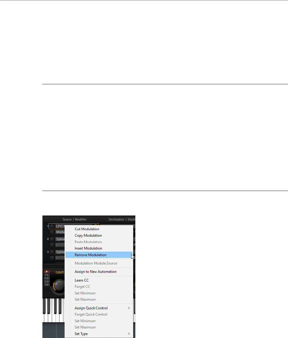
Editing Layers
Modulation Matrix
65
switched between unipolar and bipolar. An additional modifier and user-definable curves and
ranges give you further control over the modulation.
The modulation matrix is divided into two sections. On the left, you can assign modulation
sources to destinations and adjust the modulation depth. The section on the right contains
settings for the curve and range editor, where you can make further settings for the selected
modulation source.
Creating Modulations
PROCEDURE
1. Select the synth or sample layer that you want to adjust.
2. Click Show Modulation Matrix.
3. Select a modulation source and a modulation destination, for example, LFO1 as source
and Pitch as destination.
4. Use the horizontal fader below the destination to adjust the modulation depth.
5. Optional: Click the Source 2 field and select a modifier or change the polarity of the
source.
For example, select Pitch Bend as modifier and set it to unipolar.
6. Optional: Use the curve and range settings on the right to limit the modulation range
or to adjust the characteristics of the modulation.
Modulation Matrix Context Menu
Cut Modulation
Cuts the modulation data from the current slot.
Copy Modulation
Copies the modulation data from the current slot to the clipboard.
Paste Modulation
Pastes the modulation data from the clipboard to the current modulation slot.

Editing Layers
Modulation Matrix
66
NOTE
You can copy modulation rows between different programs and between different
plug-in instances.
Insert Modulation
Inserts an empty modulation slot.
Remove Modulation
Removes the modulation slot.
Name of the Assigned Source/Modulator/Destination
Depending on where you click, the assigned modulation source, the modulator, or
the modulation destination is shown on the context menu.
Assign to New Automation
Assigns this modulation source as automation parameter.
Learn CC
Allows you to assign a MIDI controller to the modulation slot.
Forget CC
Removes the MIDI controller assignment for the current slot.
Set Minimum
Allows you to set the minimum value for the MIDI controller that is assigned to
the modulation slot.
Set Maximum
Allows you to set the maximum value for the MIDI controller that is assigned to
the modulation slot.
Assign Quick Control
Allows you to assign a quick control to the modulation slot.
Forget Quick Control
Removes the quick control assignment of the modulation slot.
Set Minimum
Allows you to set the minimum value for the quick control that is assigned to the
modulation slot.
Set Maximum
Allows you to set the maximum value for the quick control that is assigned to the
modulation slot.
Set Type
•Absolute remote-controls the parameter values continuously.
Absolute mode changes the assigned parameters by overwriting them with
the current quick control value, that is, parameter changes are overwritten.

Editing Layers
Modulation Matrix
67
•Relative remote-controls the parameter values continuously.
Relative mode changes the values of the assigned parameters without
losing their relative settings, that is, parameter changes can still be heard.
•Switch Absolute switches between the minimum and maximum value.
Parameter changes are overwritten.
•Switch Relative switches between the minimum and maximum value.
Parameter changes can still be heard.
RELATED LINKS
Setting Up Automation on page 100
Modulation Matrix Parameters
Modulation Sources
LFO P1/P2
The LFOs 1 and 2 produce cyclic modulation signals.
These LFOs are polyphonic, that is, a new LFO signal is created with each new
note.
LFO M3/M4
The LFOs 3 and 4 produce cyclic modulation signals.
Amp Envelope
The amplifier envelope. This modulation source is unipolar. The shape of the
envelope determines the modulation signal.
Filter Envelope
The filter envelope. This modulation source is unipolar. The shape of the envelope
determines the modulation signal.
Pitch Envelope
The pitch envelope. This modulation source is bipolar. The shape of the envelope
determines the modulation signal.
User Envelope
The user envelope. This modulation source is bipolar. The shape of the envelope
determines the modulation signal.
Step Modulator
The step modulator of the layer. This modulation source is bipolar. It produces
cyclic, rhythmically stepped modulation signals.
Glide
The glide signal of the source. This modulation source is unipolar.

Editing Layers
Modulation Matrix
68
Key Follow
This produces an exponential modulation signal derived from the MIDI note
number. Exponential means this source works with destinations such as Pitch or
Cutoff. This modulation source is bipolar.
Note-on Velocity
Note-on velocity can be used as modulation signal. This modulation source is
unipolar.
Note-on Vel Squared
The squared version of Note-on Velocity. The harder you press the key, the higher
the modulation values.
Note-on Vel Normalized
The note-on velocity is normalized according to the velocity range of the
corresponding sample zone. At the lowest velocity of the zone, the modulation is
0, at the highest velocity, the modulation is 1.
Note-off Velocity
Note-off velocity can be used as modulation signal. This modulation source is
unipolar. Most MIDI keyboards cannot send note-off velocity messages. However,
most sequencer software is able to produce such messages.
Pitchbend
The position of the pitchbend wheel can be used as modulation signal. This
modulation source is bipolar.
Modulation Wheel
The position of the modulation wheel can be used as modulation signal. This
modulation source is unipolar.
Aftertouch
Aftertouch can be used as modulation signal. This modulation source is unipolar.
Some MIDI keyboards cannot send aftertouch messages. However, most
sequencer software is able to produce such messages.
MIDI Controller
Any of the 127 available MIDI controllers can be used as modulation signal. You
can select the MIDI controller from the corresponding submenu.
In addition, you can select the eight global MIDI controllers Contr. A-Contr. H
that can be used as placeholders in the modulation matrix. These controllers
allow you to remap specific MIDI controllers to the placeholder controllers, for
example, using the CC Mapper. This way, you can use the global controllers in
several places, and set up the assignment only once.
Quick Control
The quick controls of the layer can be used as modulation signal. You can select
the quick control from the corresponding submenu.

Editing Layers
Modulation Matrix
69
Note Expression
This submenu lists the eight Note Expression parameters that can be used as
modulation signals.
Noise
Produces a random modulation signal. This modulation source is bipolar.
Output
The audio output of the layer can be used as modulation signal. This modulation
source is unipolar.
Bus 1–16
Modulations that are sent to one of the 16 busses can be reused as sources. This
way, you can combine several modulations to produce more complex signals.
Modulation Modifiers
All modulation sources can also be used as modifiers. A modifier is used to scale the output
of the modulation source. A typical example is an LFO as a source and the modulation wheel
as the modifier. This allows you to control the intensity of the LFO modulation using the
wheel.
The Sample & Hold modifier is only available on the Source 2 pop-up menu. It takes a
sample of the modulation source whenever it receives a trigger signal. It holds the sampled
value until it receives a new trigger. This way, you can quantize a continuous modulation
signal.
The following Sample & Hold options are available:
Trigger on Note-on
Triggers the Sample & Hold modifier manually each time that you hit a key.
Trigger on LFO 1
Triggers the Sample & Hold modifier each time that the waveform of LFO 1
crosses the zero line from below.
Trigger on LFO 2
Triggers the Sample & Hold modifier each time that the waveform of LFO 2
crosses the zero line from below.
Trigger on Modulation Wheel
Triggers the Sample & Hold modifier each time that the modulation wheel
passes the center position.
Trigger on Sustain
Triggers the Sample & Hold modifier each time that you press the sustain pedal.
Sample until Release
Triggers the Sample & Hold modifier each time that you release a key.

Editing Layers
Modulation Matrix
70
Unipolar vs. Bipolar Sources
The polarity of a modulation source specifies the value range that it produces. Unipolar
sources modulate between 0 and +1. Bipolar sources modulate between -1 and +1.
• To change the polarity of a modulation source, click its Polarity button.
Modulation Depth
The horizontal fader below the destination adjusts the modulation depth.
Bypass Modulation
Click the Bypass button in front of the depth fader to bypass the modulation.
Modulation Destinations
Depending on the selected type of layer, the available modulation destinations vary.
Pitch
Modulates the pitch. For example, assign one of the LFOs to create a vibrato
effect. If Pitch is selected, the modulation depth is set in semitones (-60 to +60).
Cutoff
Modulates the filter cutoff.
For example, to create rhythmic patterns in the spectral timbre, assign the Step
Modulator.
Resonance
Modulates the filter resonance. Resonance changes the character of the filter.
For example, to accent the filter the harder you hit a key, assign Velocity to
Resonance.
Distortion
Modulates the filter distortion.
This has no effect on the Classic, HALion 3, and Waldorf filters.
Morph X
Modulates the x-axis of the filter in Morph XY mode. Use this to morph between
the filter shapes AD and BC.
Morph Y
Modulates the y-axis of the filter in Morph 2, Morph 4, or Morph XY mode. Use
this to morph between the filter shapes AB and DC, for example.
Cutoff Offset
Modulates the cutoff offset of the second filter in Dual Filter Serial or Dual Filter
Parallel mode. For example, to lower or raise the cutoff of the second filter while
you play, assign the modulation wheel.

Editing Layers
Modulation Matrix
71
Resonance Offset
Modulates the resonance offset of the second filter in Dual Filter Serial or Dual
Filter Parallel mode. For example, to lower or raise the resonance of the second
filter while you play, assign the modulation wheel.
Level
This modulation adds to the level setting. It can be used to create level offsets
using the mod wheel, for example.
Volume 1
Modulates the gain. The volume modulation multiplies with the level.
This modulation is ideal for crossfades between layers.
Volume 2
As Volume 1. Volume 1 is multiplied with Volume 2. This way, you can build more
complex modulations.
Pan
Modulates the position of the layer in the panorama. For example, to move the
layer around freely, assign the User Envelope.
Sample Start
Modulates the start position of the sample playback. For example, assign Note-
on Velocity to play back more of the attack of a sample the harder you hit a key.
This modulation destination cannot be modulated continuously. The parameter is
updated only when you hit a key.
Speed Factor
Modulates the speed factor of the sample.
Formant Shift
Modulates the formant shifting.
Osc 1/2/3 Pitch
Modulates the pitch of the corresponding oscillator.
For example, to detune an oscillator cyclically, assign one of the LFOs.
Osc 1/2/3 Level
Modulates the level of the corresponding oscillator.
For example, to fade an oscillator in and out while you play, assign the
modulation wheel.
Osc 1/2/3 Waveform
Modulates the shape and character of the corresponding oscillator.
For example, to change the character of an oscillator over time, assign one of the
envelopes.

Editing Layers
Modulation Matrix
72
Osc 1/2/3 Multi Detune
Modulates the Detune parameter of the individual oscillator voices that are
produced by multi-oscillator mode.
Osc 1/2/3 Multi Pan
Modulates the pan position of the individual oscillator voices that are produced by
multi-oscillator mode.
Osc 1/2/3 Multi Voices
Modulates the number of oscillator voices that are produced by multi-oscillator
mode.
Sub Osc Level
Modulates the level of the sub oscillator. For example, to fade in the oscillator
while you play, assign the modulation wheel.
Ring Mod Level
Modulates the level of the ring modulation effect. For example, to fade in the ring
modulation while you play, assign the modulation wheel.
Noise Level
Modulates the level of the noise generator. For example, to fade in the noise
generator while you play, assign the modulation wheel.
LFO 1/2 Frequency
Modulates the speed of the corresponding LFO.
For example, to control the speed of a vibrato effect while you play, assign
Aftertouch.
LFO 1/2 Shape
Modulates the waveform of the corresponding LFO.
For example, to vary the waveform with the playing position on the keyboard,
assign Key Follow.
Step Mod Frequency
Modulates the speed of the step modulator. For example, assign an LFO to
increase or decrease the speed cyclically.
Step Mod Slope
Modulates the shape of the edges of the step modulator if the Slope parameter is
active. For example, assign the modulation wheel to blend from hard to smooth
edges.
Amp Env Attack Time
Modulates the attack time of the amplitude envelope. This modulation
destination cannot be modulated continuously. The time is updated only when the
segment starts.

Editing Layers
Modulation Matrix
73
Amp Env Decay Time
Modulates the decay time of the amplitude envelope. This modulation destination
cannot be modulated continuously. The time is updated only when the segment
starts.
Amp Env Sustain Level
Modulates the sustain level of the amplitude envelope. This modulation
destination cannot be modulated continuously. The level is updated only when the
segment starts.
Amp Env Release Time
Modulates the release time of the amplitude envelope. This modulation
destination cannot be modulated continuously. The time is updated only when the
segment starts.
Filter Env Attack Time
Modulates the attack time of the filter envelope. This modulation destination
cannot be modulated continuously. The time is updated only when the segment
starts.
Filter Env Decay Time
Modulates the decay time of the filter envelope. This modulation destination
cannot be modulated continuously. The time is updated only when the segment
starts.
Filter Env Sustain Level
Modulates the sustain level of the filter envelope. This modulation destination
cannot be modulated continuously. The level is updated only when the segment
starts.
Filter Env Release Time
Modulates the release time of the filter envelope. This modulation destination
cannot be modulated continuously. The time is updated only when the segment
starts.
Pitch Env Start Level
Modulates the level of the first pitch envelope node. This modulation destination
cannot be modulated continuously. The level is updated only when the segment
starts.
Pitch Env Attack Time
Modulates the attack time of the pitch envelope. This modulation destination
cannot be modulated continuously. The time is updated only when the segment
starts.
Pitch Env Attack Level
Modulates the level of the second pitch envelope node. This modulation
destination cannot be modulated continuously. The level is updated only when the
segment starts.

Editing Layers
Modulation Matrix
74
Pitch Env Decay Time
Modulates the decay time of the pitch envelope. This modulation destination
cannot be modulated continuously. The time is updated only when the segment
starts.
Pitch Env Sustain Level
Modulates the sustain level of the pitch envelope. This modulation destination
cannot be modulated continuously. The level is updated only when the segment
starts.
Pitch Env Release Time
Modulates the release time of the pitch envelope. This modulation destination
cannot be modulated continuously. The time is updated only when the segment
starts.
Pitch Env Release Level
Modulates the level of the last pitch envelope node. This modulation destination
cannot be modulated continuously. The level is updated only when the segment
starts.
User Env Start Level
Modulates the level of the first user envelope node. This modulation destination
cannot be modulated continuously. The level is updated only when the segment
starts.
User Env Attack Time
Modulates the attack time of the user envelope. This modulation destination
cannot be modulated continuously. The time is updated only when the segment
starts.
User Env Attack Level
Modulates the level of the second user envelope node. This modulation
destination cannot be modulated continuously. The level is updated only when the
segment starts.
User Env Decay Time
Modulates the decay time of the user envelope. This modulation destination
cannot be modulated continuously. The time is updated only when the segment
starts.
User Env Sustain Level
Modulates the sustain level of the user envelope. This modulation destination
cannot be modulated continuously. The level is updated only when the segment
starts.
User Env Release Time
Modulates the release time of the user envelope. This modulation destination
cannot be modulated continuously. The time is updated only when the segment
starts.

Editing Layers
Modulation Matrix
75
User Env Release Level
Modulates the level of the last user envelope node. This modulation destination
cannot be modulated continuously. The level is updated only when the segment
starts.
Bus 1-16
You can send any modulation to one of the 16 busses, for example, to produce
more complex modulation signals. Select the bus that you want to send the
signals to as a destination. To use the modulation that was sent to a bus, assign
the corresponding bus as a modulation source.
Curve and Range Editor
You can set up a curve and range for each modulation source.
• The curve editor allows you to change the characteristics of a modulation. The
displayed curve is superimposed on the modulation source.
This way, you can change the modulation from linear to exponential or logarithmic, for
example.
• By setting the minimum and maximum values, you limit the modulation to a specific
range only. In addition, you can specify an offset and a range for the modulation.
For example, with an offset and range of +50 %, only the second half of the displayed
curve is superimposed on the modulation.
• If a MIDI or Note Expression controller is selected as modulation source, the
Smoothing parameter is available. This allows for parameter changes to occur more
gradually. Set this to Default to use the global Smoothing parameter set up on the
Options page or enter a value in the value field.
The curve editor offers different presets that you can select from the Shape pop-up menu
above the curve. To set up your own curve, select the Custom preset.
You can edit the custom curve in the following way:
• Double-click in the editor to insert a new node.
• Double-click on a node to delete it.
• Drag the nodes to new positions to adjust the basic shape of the curve.
• Drag the lines between the nodes up or down to change the curvature.

FlexPhraser
76
The FlexPhraser is an arpeggio and phrase player.
Each program features up to five FlexPhrasers: one for each layer and one for the program.
While the program FlexPhrasers always work with phrases, the functionality of layer
FlexPhrasers changes with the layer type. For synth, sample, instrument, or drum layers, a
FlexPhraser can play back anything from basic synth arpeggios over dynamic drum phrases
to realistic accompaniment phrases for guitar, bass, piano, etc.
You can select from a great variety of phrases that suit a wide range of musical instruments
and styles. Depending on the selected phrase, the FlexPhraser uses your live playing to
modify the phrase in real-time. This allows you to re-harmonize phrases by playing different
chords, for example.
If you are working with loop layers, the FlexPhraser triggers the slices of the loop with their
original timing and order. You can trigger a transposed version of the loop, playing higher or
lower in pitch. In addition, you can vary the order with a random function and export the slice
sequence to your host sequencer via drag and drop.
NOTE
You can play the individual slices or the entire loop. The lower half of the key range triggers
the loop and the upper half is used to play single slices. The loop keys are displayed in green
on the keyboard.
Presets
FlexPhraser presets contain the selected phrase, as well as the performance settings of the
FlexPhraser, such as Tempo, Tempo Scale, Loop, Swing, etc.
NOTE
Presets can only be saved and loaded for phrases, not for sliced loops.
RELATED LINKS
Handling Section and Module Presets on page 13
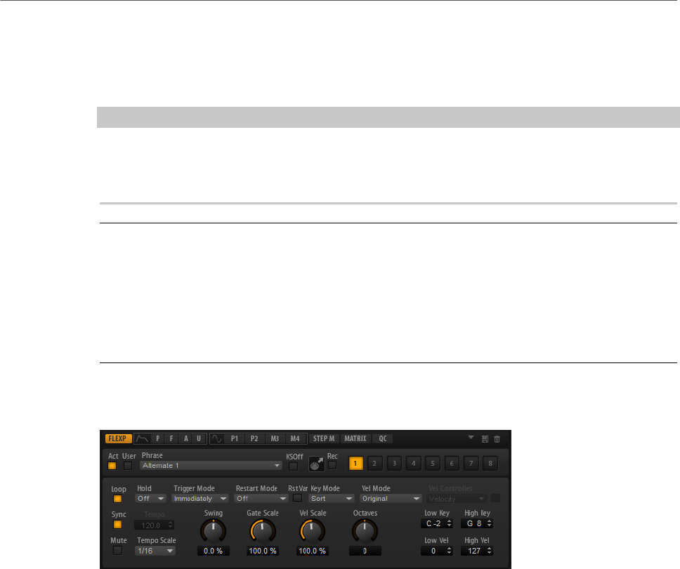
FlexPhraser
Loading Phrases
77
Loading Phrases
Phrases are sorted into subfolders, according to the type of instrument. Each instrument
subfolder contains phrases of different musical styles.
NOTE
Some FlexPhrases make extensive use of key switches to switch between multiple playing
styles of an instrument while playing. These phrases can be found on the Construction Sets
submenu. They work best with the corresponding instrument layers.
PROCEDURE
1. At the top of the FlexPhraser, click in the Phrase field.
2. On the pop-up menu, open the submenu for the instrument, and select the phrase that
you want to load.
In general, you can apply any phrase to any type of instrument. However, a phrase for
guitar might not be suitable for use with a piano, for example.
FlexPhraser Parameters
Act
Activates the FlexPhraser.
User
Activates the user phrase.
If this button is activated, the Show Editor Page button becomes available. Click it
to open the user phrase editor.
Phrase
Allows you to select a phrase.
KSOff (Key Switches Off)
Construction set phrases that make use of key switches and noises, such as fret
noises for guitar phrases, for example, usually work only with programs for the
same type of instrument. Programs without key switches and noises interpret
these events as regular notes and includes them during playback, which yields
unexpected results. To avoid the playback of key switches and noises, activate
KSOff.

FlexPhraser
FlexPhraser Parameters
78
NOTE
KSOff filters out any note events that do not transpose with your playing.
Therefore, it is not recommended for the use with drum phrases.
MIDI Record
Allows you to record the MIDI output of the FlexPhraser.
Variation buttons
Allow you to create up to eight variations of your phrase.
Loop
If this option is activated, the phrase plays in a loop.
Sync
Synchronizes the phrase to the tempo of your host application.
NOTE
In addition, you can set Restart Mode to Sync to Host. This aligns the phrase with
the beats and measures of your host application.
Mute
Mutes the FlexPhraser. The phrase still plays in the background. If you deactivate
Mute, playback resumes immediately.
Hold
Allows you to prevent the phrase from stopping or changing when the keys are
released.
• If Off is selected, the phrase changes as soon as you release a key. The
phrase stops immediately when you release all keys.
• If On is selected, the phrase plays to the end, even if the keys are released.
If Loop is activated, the phrase repeats continuously.
• If Gated is selected, the phrase starts to play when the first key is played. It
plays silently in the background, even if the keys are released, and resumes
playback at the current position when you press any of the keys again. This
way, you can gate the playback of the phrase.
Trigger Mode
Determines at which moment the FlexPhraser scans for new notes that you play
on the keyboard.
• If this is set to Immediately, the FlexPhraser scans for new notes all the
time. The phrase changes immediately in reaction to your playing.
• If this is set to Next Beat, the FlexPhraser scans for new notes at every
new beat. The phrase changes in reaction to your playing on each new beat.
• If this is set to Next Measure, the FlexPhraser scans for new notes at the
start of new measures. The phrase changes in reaction to your playing on
each new measure.

FlexPhraser
FlexPhraser Parameters
79
Restart Mode
• If this is set to Off, the phrase runs continuously and does not restart at
chord or note changes.
•New Chord restarts the phrase on new chords.
NOTE
The phrase does not restart upon notes that are played legato.
•New Note restarts the phrase with each new note that you play.
•Sync to Host aligns the phrase with the beats and measures of your host
application each time that you start the transport.
RstVar (Restart on Variation Change)
This option is available for new chords and new notes. If this button is activated,
changing a variation restarts the FlexPhraser, even if no new notes or chords
were triggered.
Key Mode
Defines whether the order in which the notes are played on the keyboard affects
the playback of the phrase.
• If Sort is selected, the notes are played in the order of the selected pattern.
The chronological order does not have any influence.
• If As Played is selected, the notes are played in the order in which you play
them on the keyboard.
• If Direct is selected, the phrase creates controller events instead of notes.
You hear the notes that you play plus any controller events of the phrase,
such as pitch bend, volume, pan, etc.
Vel Mode
• If Original is selected, the notes of the phrase play with the velocity that is
saved in the phrase.
• If Vel Controller is selected, you can choose a velocity controller that is
used to generate or modulate the velocities of the notes.
• If Original + Vel Controller is selected, the phrase velocity is determined by
the combination of the velocity saved in the phrase and the velocity derived
from the velocity controller.
Vel Controller
If the Vel Mode pop-up menu is set to Vel Controller or Original + Vel Ctrl., the
Vel Controller pop-up menu is available. It allows you to generate or modulate
the velocities of the notes using the incoming controller values.
• If Velocity is selected, the triggered notes get the velocity of the note that
you play.
• Select Controller to open a submenu where you can select a MIDI
controller.
The value of this MIDI controller is used as velocity for the triggered notes.

FlexPhraser
FlexPhraser Parameters
80
• If Aftertouch is selected, the triggered notes get their velocity from the
aftertouch controller.
• If Poly Pressure is selected, the triggered notes get their velocity from the
poly pressure controller. This allows you to control the velocity per key.
Fetch
If the Vel Controller pop-up menu is set to Aftertouch, Poly Pressure, or a MIDI
controller, the Fetch option can be used to change the way that the notes are
generated.
• If Fetch is activated, the first note that you play defines the initial velocity.
As soon as the controller value exceeds this velocity, new notes get their
velocity from the controller.
• If Fetch is deactivated, the generated notes get their velocity from the
current controller value.
NOTE
Fetch is not available if the Vel Controller pop-up menu is set to Velocity.
Tempo
If Sync is deactivated, you can use the Tempo control to set the internal playback
speed of the FlexPhraser. The playback speed of the phrase is specified in BPM.
If Sync is activated, the Tempo parameter is not available.
Tempo Scale
Defines the rate at which notes are triggered, that is, the speed at which the
phrase is running. In addition to the Tempo parameter, this gives you further
control over the playback speed. You can specify a value in fractions of beats. You
can also set dotted and triplet note values.
For example, if you change the Tempo Scale setting from 1/16 to 1/8, the speed
is cut in half. If you set it to 1/32, the speed is doubled. Other values increase or
decrease the speed accordingly.
Swing
Shifts the timing of notes on even-numbered beats. This way, the phrase gets
a swing feeling. Negative values shift the timing backward, and the notes are
played earlier. Positive values shift the timing forward, and the notes are played
later.
Gate Scale
Allows you to shorten or lengthen the notes of the phrase. At a value of 100 %,
the notes play with their original gate length.
Vel Scale
Allows you to raise or lower the note-on velocities of the phrase. At a value of 100
%, the notes are played with their original velocity.

FlexPhraser
Recording the MIDI Output of the FlexPhraser
81
Octaves
Extends the phrase playback to include higher or lower octaves. Positive
settings extend the playback to higher and negative settings to lower octaves.
For example, a value of +1 first plays the phrase in the octave range that you
originally played. Then, it repeats the phrase one octave higher.
Key Range
The Low Key and High Key parameters determine the key range that is used to
trigger phrase playback.
Velocity Range
The Low Vel and High Vel parameters determine the velocity range that is used to
trigger phrase playback.
Recording the MIDI Output of the FlexPhraser
The phrases played by the FlexPhraser depend on the notes that are played and can
therefore not be exported directly. However, it is possible to generate exportable phrases by
recording the MIDI output of the FlexPhraser.
PROCEDURE
1. Click Record FlexPhraser MIDI Output.
The arrow in the Drag MIDI field starts blinking to indicate record mode.
2. Play some notes.
3. When you are done, click Record FlexPhraser MIDI Output again.
Recording stops. In the Drag MIDI field, the arrow remains lit to indicate that a MIDI
phrase can be exported.
4. Click the Drag MIDI field and drag the phrase on a MIDI track in your host sequencer
application.
Phrase Playback Types
HALion Sonic features a huge amount of phrase types, organized in submenus and
categorized according to functional descriptions or musical styles, such as Classic Arp,
Synth Seq, Chord Seq, Bass, etc.
The Construction Sets submenu contains phrases made for instrument layers. These
phrases use key switches to switch between different playing styles, to increase the realism
of your performance. The phrases that can be found in the various other categories use a
number of different playback types to allow phrase-specific user interaction while playing.
For example, with drum patterns, pressing any note triggers the same rhythm pattern. Other
phrases are played back using only the played note and its octave notes. And if you play back
a programmed sequence according to the played chord, the following applies:
• If you press a single key, the phrase is played back using the programmed sequence,
which means that notes other than the ones you play are triggered.

FlexPhraser
Variations
82
• If you are adding notes to those already held, the sequence changes accordingly, for
example, the phrase plays back according to the chord you play.
Variations
For each FlexPhraser, you can set up 8 different variations of phrases. You can switch
between them with the variation buttons at the top right.
You can remote-control the variation buttons using the trigger pads, which gives you the
possibility to switch between variations by playing the trigger keys that are assigned to the
trigger pads.
NOTE
To avoid that the variation switches in the middle of a beat or measure, use the trigger
modes Next Beat or Next Measure.
Creating FlexPhraser Variations
PROCEDURE
1. Click one of the variation buttons at the top right of the FlexPhraser.
2. You can either start from scratch or base the new variation on an existing variation.
•To start from scratch, assign a phrase and edit the FlexPhraser settings.
•To use an existing variation as base, use the context menu commands Copy
FlexPhraser Variation and Paste FlexPhraser Variation.
RESULT
The variation can now be recalled by clicking the corresponding variation button.
NOTE
The parameters Loop, Sync, Hold, Trigger Mode, Restart Mode, Key Mode, Vel Mode, Low/
High Key, and Low/High Vel are not part of the variations. You set them up only once for each
inserted FlexPhraser module.
RELATED LINKS
Switching between Variations on page 26
User Phrases
The user pattern of the FlexPhraser has up to 32 steps. Each step has an adjustable
velocity, gate length, and transpose value. By setting the steps, adjusting their length,
or leaving pauses, you define the rhythm of the user pattern. Consecutive steps can be
combined to create longer notes. By selecting a mode, you define how the notes play back. In
addition, there are two MIDI control sequences, that is, each step can send two modulation
signals.In addition, there are three MIDI control sequences, that is, each step can send three
modulation signals.
To create your own phrases, activate User and Show Editor Page.

FlexPhraser
User Phrases
83
For user phrases, the regular FlexPhraser parameters are available, except for the KSOff
button.
User Phrase Editor
In the user phrase editor, you can set up your user phrases.
To open the user phrase editor, click Show Editor Page .
You can display the velocity curve or two MIDI controller sequences for the phrase.
Phrase
To load a phrase, select it from the Phrase pop-up menu.
NOTE
Saved phrases include the Mode, Key Replace, and Wrap parameters, as well
as the steps with their Level, Length, and Legato settings. The selected MIDI
controllers or any settings on the main FlexPhraser page are not saved.
Mode
Determines how the notes are played back.
• If Step is selected, the last note that is received triggers a monophonic
sequence.
• If Chord is selected, the notes are triggered as chords.
• If Up is selected, the notes are arpeggiated in ascending order.
• If Down is selected, the notes are arpeggiated in descending order.
• If Up/Down 1 is selected, the notes are arpeggiated first in ascending, then
in descending order.
• If Up/Down 2 is selected, the notes are arpeggiated first in ascending, then
in descending order. This mode depends on the set Key Mode.
If Key Mode is set to Sort, the highest and the lowest note are repeated.
If Key Mode is set to As Played, the first and the last note are repeated.
• If Down/Up 1 is selected, the notes are arpeggiated first in descending,
then in ascending order.
• If Down/Up 2 is selected, the notes are arpeggiated first in descending,
then in ascending order. This mode depends on the set Key Mode.
If Key Mode is set to Sort, the highest and the lowest note are repeated.
If Key Mode is set to As Played, the first and the last note are repeated.
• If Random is selected, the notes are arpeggiated in random order.
Groove Q
To adapt the timing of a phrase to an external MIDI file, you can drop this MIDI
file on the Groove Quantize drop field. You can quantize the playback of the user
phrase to the timing of a sliced loop by dragging its MIDI file from the MIDI export
drag field to the Groove Quantize drop field.
The Groove Quantize Depth parameter to the right of the drop field determines
how accurately the phrase follows the timing of the MIDI file.
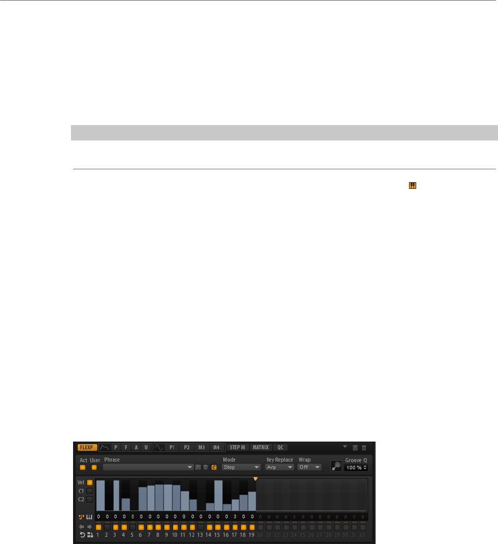
FlexPhraser
User Phrases
84
Key Select
The FlexPhraser scans the keyboard and writes the keys that are pressed into a note buffer.
Depending on the selected Key Mode, this note buffer is sorted either by pitch or in the order
in which you play the keys.
Key Select allows you to play back a defined key from the note buffer. You can set up Key
Select for each step separately, which allows you to create very elaborate phrases.
NOTE
Key Select cannot be used in Step or Chord mode.
• To access the Key Select values of the steps, click Show Key Values to the left of the
editor.
• To switch between the available Key Select values for a step, click the value and drag
up/down or use the scroll wheel.
The following options are available:
•P (Phrase) plays the note of the user phrase, according to the selected mode, for
example, Up, Down, Up/Down 1, etc.
• The settings 1 - 8 play the corresponding keys from the note list. Which key is
played depends on the Key Mode setting. For example, if Key Mode is set to Sort,
the setting 1 plays the lowest key.
•L (Last) always plays the last key from the note buffer. Depending on the Key
Mode, this is the highest note or the last note in the note buffer.
•A (All) plays all keys from the note buffer as a chord.
Velocity Curve
• To display the velocity curve, activate the Vel button on the left.
Key Replace
With this parameter, you can deactivate the Key Select function or specify how
missing keys are replaced.
For example, if Key Select is set to 1 - 2 - 3 - 4 and you play a chord with 3 notes,
key 4 is considered missing.
•Off deactivates Key Replace and Key Select. The selected arpeggio plays
back normally.
•Arp replaces the missing keys with the note that the arpeggio would
normally play.
•Rest does not replace any missing keys. The arpeggio plays a rest instead.
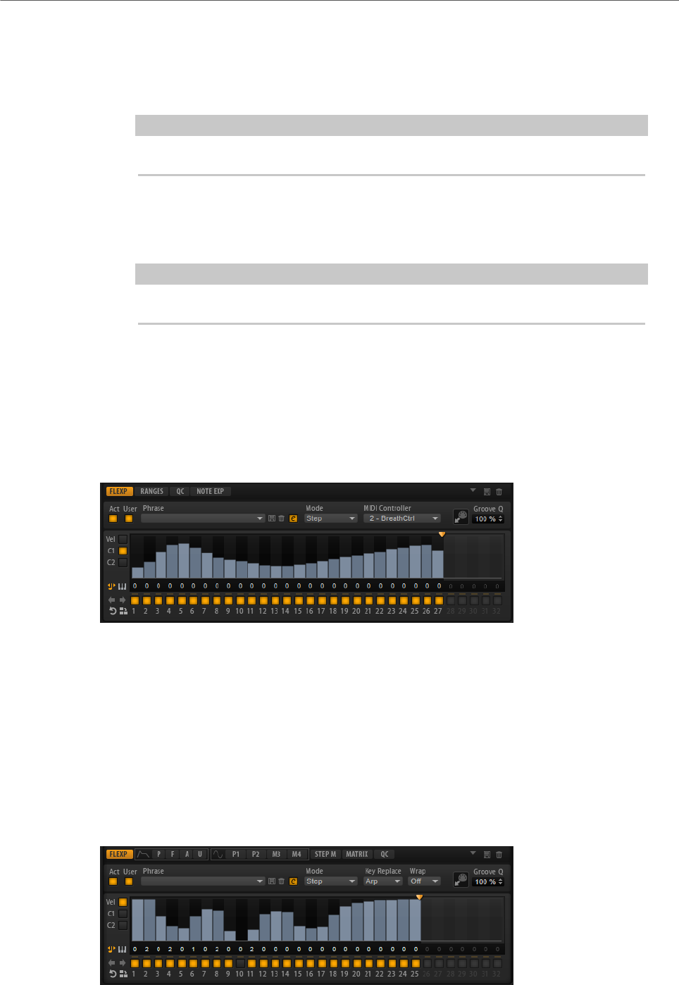
FlexPhraser
User Phrases
85
•1st replaces the missing keys by the first note in the note buffer.
•Last replaces the missing keys with the last note in the note buffer.
•All replaces the missing keys with all notes in the note buffer. The notes
are played as a chord.
NOTE
Key Replace can be set separately for each variation.
Wrap
For all modes except Step and Chord, you can use this parameter to restart the
arpeggio after a specified number of steps.
NOTE
Deactivated steps are taken into account.
In Step and Chord mode, this parameter only affects the Octaves setting.
If the Octaves parameter is active, the arpeggio traverses the octaves and
restarts from the original octave after the specified number of steps.
Controller Curve
To show a controller curve, click one of the controller buttons on the left.
MIDI Controller
Allows you to select the MIDI controller that you want to use.
Editing User Phrases
You can make detailed settings for the user phrase in the editor for the user phrases.
To set up the phrase, activate the Vel button to the left of the step display.
To set up a controller curve for the phrase, activate one of the controller buttons to the left of
the step display.
FlexPhraser
User Phrases
86
•To specify the number of steps for the pattern, drag the pattern length handle to the
right or left.
Activating Steps
A phrase can contain up to 32 steps. Only the steps that are activated are played.
• To activate a step, click its On/Off button below the display.
This can be necessary if you change the gate length of one step so that it overlaps the
following step, thereby deactivating it.
NOTE
If you activate a step that was inactive because of an overlapping previous step, the
previous step is shortened.
• To activate all steps, right-click in the step display and select Enable All Steps from
the context menu.
Editing Steps
The height of a step represents its value. You can edit the steps in the following way:
• To activate all steps, select Enable All Steps from the context menu.
• To adjust a value, click a step and drag up or down.
• To adjust multiple steps, click and draw a curve.
• To adjust the velocity of all steps relatively, Shift-click and drag.
• To draw a ramp with steps, hold down Alt and draw a line.
• To draw symmetric ramps at the beginning and the end of the sequence, hold down
Shift-Alt and draw a line.
• To transpose a step, click in the field below it and enter the number of semitones for
the transposition.
NOTE
You can only transpose steps if Show Transpose Values is activated.
• To reset the velocity of a step to 127, Ctrl/Cmd-click the step.
• To reset the velocity of all steps to 127, hold Shift-Ctrl/Cmd and click a step.
• To introduce a legato between 2 steps, click the number below the first of these steps,
so that a small arrow is shown.
If Legato is activated, the Gate Scale parameter is not taken into account.
For velocity steps, the width of a step represents its gate length.
• To adjust the gate length of a step, drag its right border.
• To adjust the gate length of all steps, hold down Shift and drag the right border of a
step.

FlexPhraser
User Phrases
87
You can only adjust the length this way until a step reaches the next step. If you
increase the gate length of a step so that it overlaps the following step, this following
step is deactivated.
• To reset the length of a step to 1, Ctrl/Cmd-click its highlighted right border.
• To reset the length of all steps, hold down Shift-Ctrl/Cmd and click on a highlighted
right border.
• To fill the gaps between consecutive steps, select Fill Gap or Fill All Gaps from the
context menu.
Each MIDI controller lane can send a MIDI controller. By selecting the same MIDI controller
as source in the Modulation Matrix, you can modulate any of the destinations with the MIDI
controller sequence.
• To assign a controller, open the MIDI Controller pop-up menu and select the controller
or use the corresponding control on your hardware.
Adjusting the Phrase
• To shift the rhythm of the phrase, click Shift Phrase Right or Shift Phrase Left .
If you shift the rhythm of the phrase to the left, the first step is moved to the end. If you
shift the phrase to the right, the last step is moved to the beginning.
• To reverse the phrase, click Reverse Phrase .
• To duplicate short phrases, click Duplicate Phrase .
NOTE
The maximum number of steps is 32. Therefore, phrases that contain more than 16
steps cannot be duplicated entirely.

Managing Your Sounds
88
About Programs, Layers, Multis, Macro Pages, and Presets
Programs
A program is a complex instrument or sound that can consist of up to 4 layers. Often, a
program contains a single layer that comes with all necessary components, such as the
synthesis part or insert effects. Programs add the possibility of combining different layers to
build up more complex sounds or to create combinations of sounds that you want to load as a
unit. A typical example is a bass/piano split sound or a piano/string layer sound.
Because of the various layer types that come with HALion Sonic, these combinations can do
a lot more. For example, think of combining a pulsating synthesizer sequence with a sliced
loop completed by a bass on the lower keys, and so on. Finally, add some effects to individual
layers or to the whole program and you get a unique sound experience.
Layers
Programs are combinations of up to 4 layers. HALion Sonic offers 5 different layer types. You
can choose between synth, sample, instrument, drum, and sliced loop layers. Each layer type
is based on an individual sound architecture and has a dedicated editor.
Synth and Sample Layers
For synth and sample layers, you get access to a synthesizer editor with
components such as a highly flexible filter section, powerful multi-stage
envelopes, LFOs, a step modulator, and a modulation matrix. These layer types
differ in their basic sound source. While a synth layer provides an oscillator
section with three main oscillators, a sub oscillator, a noise generator, and a ring
modulation stage, the sample layer loads a specific multi-sample instead.
Drum Layers
The drum layers load a multi-sampled drum set, for which you can individually
adjust the most important parameters of each drum instrument. Each drum
instrument can be set to a specific pan position or an individual output, or it can
be filtered, reversed, and so on.
Loop Layers
Loop layers load a sliced loop, that is, a combination of a loop-specific MIDI
phrase and the individual slices mapped across the keyboard. You can either play
the original loop or a transposed version of it, or trigger single slices manually.
Each slice can be modified with the same parameters as the drum instruments.

Managing Your Sounds
Loading Programs
89
Instrument Layers
Instrument layers contain several multi-samples of an instrument that can be
parts of single sounds or different articulations. These sublayers are called
expressions. You can modify expression parameters. By switching off an
expression, you can shorten the load time of a sound.
Multis
HALion Sonic is a multitimbral plug-in that can load up to 16 sounds (or programs) and
combine them. This combination is called a multi-program, or multi for short. You can use
multis to layer several programs or to create split sounds by setting several programs to the
same MIDI input channel, for example. However, the most common usage is to create sound
sets with different instruments set to individual MIDI channels.
VST Sound Instrument Sets and Macro Pages
VST Sound Instrument Sets from Steinberg provide additional content for VST instruments
based on the HALion technology. They come with their own edit pages, called macro pages,
that feature a customized look and a collection of controls that match the functions of
the VST Sound Instrument Set. When you edit a program or layer of a certain VST Sound
Instrument Set, the accompanying macro page opens. For details on the functions and
controls of a particular macro page, refer to the documentation that comes with the
corresponding VST Sound Instrument Set.
Presets
You can save and load all types of sounds as presets, that is, you can create presets for
single programs, for layers, and for multis.
Content Files and Folder Structure
HALion Sonic comes with a large amount of ready-to-use sound content, made up of
hundreds of multis, programs, and layers. This content is write-protected. You can edit files
while they are loaded, but you cannot overwrite the factory content files.
To save edits to the factory content, save the files under a new name. These files get the file
name extension .vstpreset and are referred to as user content. They can be searched and
categorized in the same way as factory content.
User content is saved in a predefined folder structure on your hard disk. You can create
subfolders within this structure to facilitate moving or exchanging content.
Loading Programs
There are several ways to load programs:
• Via drag and drop from the File Explorer/Mac OS Finder
• Via the slot context menu
• By clicking the Load Program button at the right of the slot
NOTE
Programs containing lots of sample data may take some time to load.
Managing Your Sounds
Load Dialog
90
RELATED LINKS
Slot Context Menu on page 91
Load Dialog
The Load dialog contains many of the MediaBay functions, allowing for very sophisticated
search criteria.
RELATED LINKS
Applying Filters on page 93
Managing Files via the MediaBay on page 93
Results List on page 94
Slot Rack
The Slot Rack has 16 slots. Each slot can hold a program, that is, you can work with 16
programs at the same time.
Once a program is loaded in the Slot Rack, it can be played and edited.

Managing Your Sounds
Slot Rack
91
Slot Context Menu
The context menu provides a number of functions for managing programs.
Load Program
Opens the program loader. Double-click a program or layer to load it into this
slot.
Save Program
Saves the program. If you try to overwrite write-protected factory content, a
dialog opens that allows you to save the edited program under a new name.
Save Program As
Allows you to save the program under a new name.
Save All Programs
Allows you to save all programs as a VST preset.
Remove Program
Removes the program from the slot.
Init Program
Loads the Init program. This contains a neutral synth layer.
Revert to Last Saved Program
Discards any changes that you made to the program since the last time it was
saved.
Cut Program
Copies the program and removes it from the slot.
Copy Program
Copies the program.
Paste Program
Pastes the copied program into the slot. If the slot already contains a program, it
is replaced.
Rename Program
Allows you to rename the program.
Reset Slot
Resets the slot to the default values.
Reset All Slots
Resets all slots to the default values.
NOTE
You can also cut, copy, and paste programs from one plug-in instance to another.

Managing Your Sounds
Managing and Loading Files
92
Managing and Loading Files
You can use the MediaBay to manage, navigate to, and load different file types.
Managing Multis
Multis can load multiple sounds or programs and combine them.
You can use multis to layer several programs or to create split sounds by setting several
programs to the same MIDI input channel, for example. However, the most common usage is
to create sound sets with different instruments set to individual MIDI channels.
A multi-program contains all plug-in parameters. If you use HALion Sonic as a plug-in in a
Steinberg DAW, these multis are listed in the Preset Management pop-up menu of the host
application. You can drag multis and programs from the MediaBay to a slot in HALion Sonic.
If you use HALion Sonic as a plug-in in a different host application, you can use the preset
functionality from the host application or the multi management features provided by HALion
Sonic.
Loading Multis
You can load multis in the following ways:
• Open the MediaBay and double-click a multi or drag a multi onto the multi slot.
• Click the Load Multi-Program button in the multi slot to open the Load Multi-Program
dialog, select a multi, and click OK.
Renaming Multis
PROCEDURE
•To rename a multi, click in the name field, enter a new name, and press Return.
Removing Multis
• To remove all programs of the current multi, click the Remove All Programs button on
the toolbar of the multi program rack.
This also resets all slot parameters and removes effects from the slot busses.
However, AUX and Master effects are not removed.
Clearing the Plug-In Instance
• To reset the entire plug-in instance to an empty state, right-click the multi loader and
select Clear Plug-in Instance from the context menu.
Saving Multis
PROCEDURE
1. Click the Save Multi-Program button.
2. Enter the name of the multi.
3. Assign any attributes that you want to use and click OK.

Managing Your Sounds
Managing and Loading Files
93
If the entered name already exists, the Make Unique Name option adds a number
suffix to the name of the new multi.
Saving a Multi as Default
• To specify a default multi to be loaded with HALion Sonic, use the Save as Default
command on the context menu for the multi loader.
Creating Subfolders for User-Defined Multis
You can create subfolders inside the user preset folder to organize presets.
• To create a new folder, click the Create New Folder icon at the top left of the Save
Multi-Program dialog.
Navigating Through the Folder Hierarchy
You can move through the folder hierarchy using the three navigation buttons at the top left
of the dialog.
These buttons allow you to navigate to the previous or next browse location, or browse the
containing folder.
Editing Attributes
You can edit the attribute values that are assigned to the preset.
PROCEDURE
1. Open the Save Multi-Program dialog and navigate to the New Preset Tags section.
2. To edit an attribute, click on a value field and enter the new name or value.
3. Click OK to save the preset.
Managing Files via the MediaBay
The MediaBay functionality can be found on the Load page.
In the top section of the MediaBay, you specify which sounds to look for. The lower section
presents the corresponding results.
•To adjust the size of the two sections, drag the divider at the top of the results list.
Applying Filters
Category Filter
You can filter the results list based on up to 4 filter criteria using the configurable attribute
columns. The standard attributes are Category, Sub Category, Style, and Character.
Only the files that match the filter are displayed in the results list.
• To define the filter, click on specific values in the columns.
• To refine the filter, select more values from other columns.
Managing Your Sounds
Managing and Loading Files
94
• To select different filter criteria, click the column header and select a different
attribute from the submenu.
Content Set Filter
Use the Select Content Set pop-up menu to search a specific content set. By default, the
search is performed in all installed content sets.
Results List
The results list shows all files that have been found according to the category filter.
Text Search
In the text search field on the results list toolbar, you can enter text contained in
the name or any of the attributes of a preset that you are looking for. The results
list is updated immediately and the category search section above shows all
categories that contain presets matching the text search.
To reset the text-based result filter, click Clear Search Text next to the search
field.
View Filters
The toolbar has three filter buttons that allow you to define which preset types to
display: multis, programs, or layers. In the results list, the corresponding icon is
shown to the left of the preset name.
Rating Filter
You can limit the results list according to the rating of the presets. Use the rating
slider to define the minimum rating.
Managing Your Sounds
Managing and Loading Files
95
Content Filters
The content filter buttons allow you to define whether to show all presets, only
the factory presets, or only your user presets.
Columns
The columns show all the attribute values for the presets that match the filters
that you set up in the top section.
Set Up Result Columns
Allows you to select which attribute columns to display on the toolbar.
Results Counter
The number of presets that match the filter criteria is displayed at the right of the
toolbar.
Configuring the Results List
•To configure which attributes are shown in the results list, click Set up Result Columns
in the upper right corner of the results list and activate the corresponding entries. New
attributes are added at the right of the list.
•To reorder the columns in the results list, drag the column headers to another
position.
•To change the sorting of the list entries, click the column header. The triangle in the
column header shows the sorting direction.
Assigning General MIDI Program Change Numbers to Sounds
PROCEDURE
1. In the MediaBay, click Set up Result Columns on the title bar of the lower section.
2. Select Musical> GM Sound.
3. Select the sound to which you want to apply the GM program change number.
4. In the GM Sound column for the sound, select the General MIDI program change
number that you want to use.
You can assign the same GM Sound program number several times. If a program
number is used more than once, the Rating attribute can be used to decide which
program to load.

Managing Your Sounds
Managing and Loading Files
96
RESULT
Now, you can use MIDI program change messages to load the assigned sounds into the slot
of the corresponding MIDI channel.
NOTE
Slot 10 ignores any program change messages and keeps the loaded drum set.
Loading Programs into Slots
To load a program into one of the slots of the Slot Rack, you have the following possibilities:
• Select the slot into which you want to load the program, and double-click the program
in the results list.
• Drag a program from the results list to an empty space in the Slot Rack to create a
new slot.
If you drag it to an existing slot, the current program is replaced.
• Right-click the program and select Load Program into selected Slot from the context
menu.
Importing Presets
You can import program presets from any file location using the File Explorer/Mac OS
Finder.
PROCEDURE
1. Select the preset in the File Explorer/Mac OS Finder.
2. Drag it to the MediaBay.
RESULT
The imported presets are copied to your user folder.
Editing Preset Attributes
Presets can be described by using a predefined set of attributes.
PROCEDURE
1. In the New Preset Attributes section of the Save dialog, click in the field of the
attribute value that you want to set.
Depending on the attribute, a menu or a dialog opens.
2. Select a value.
Attribute values are written into the corresponding preset files.
NOTE
If you change the attributes for write-protected factory presets, these changes are only
saved in the MediaBay database, not in the preset file.

Managing Your Sounds
Managing and Loading Files
97
Deleting User Presets
• To delete a user preset, right-click it and select Delete from the context menu.
NOTE
Factory presets cannot be deleted.
Multi Chains
On the Multi page, you can combine up to 128 multis as a multi chain.
You can step through the multis manually or via MIDI control change messages. This feature
is particularly useful when performing live on stage. It allows you to set up a list of sounds
that follows the order of their appearance during your performance, for example.
NOTE
•To use a hardware controller to switch between the multis, add MIDI controllers to the
Load Previous Multi/Load Next Multi buttons.
•If Multi Mode is selected on the Program Change pop-up menu on the Options page,
you can use program change messages to switch between the multis.
Setting Up a Multi Chain
PROCEDURE
1. On the Multi page, click the down arrow button for a list entry to open the Load Multi-
Program dialog.
2. Select a multi and click OK.
3. Select the next slot in the list and repeat the procedure.
4. Continue until all multis that you want to add are part of the chain.
AFTER COMPLETING THIS TASK
You can rearrange the order of a chain by dragging an entry to a new position in the list.
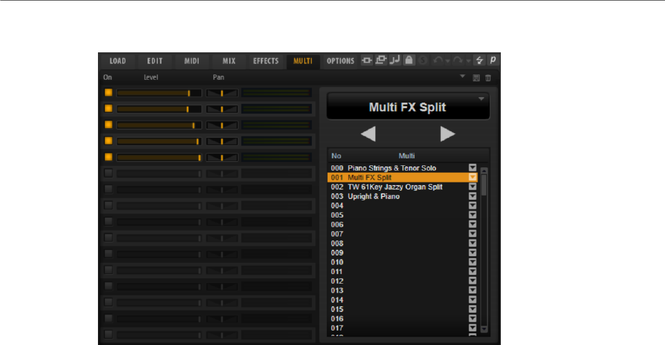
Managing Your Sounds
Managing and Loading Files
98
Multi Page
The list of multis in your chain is displayed on the right. If you select a multi in this list, its
name is displayed in the field above the list, and the corresponding programs are displayed
on the left.
• To load the next or the previous multi, use the Load Previous Multi/Load Next Multi
buttons above the list.
• To load a specific multi, select it in the list.
On
Activates/Deactivates the corresponding program.
Level
Sets the level of the corresponding program.
Pan
Sets the pan of the corresponding program.
Active Multi Display
The field at the top op the multi list shows the selected multi.
Click the arrow button on the right to open a pop-up menu with the following
options:
•Clear Multi Chain removes all multis from all slots in the list.
•Remove Selected Multi removes the selected multi from its slot in the list.
Load Previous Multi/Load Next Multi
Use these buttons to step through the multi list.
• To assign a MIDI controller to a button, right-click it, select Learn CC, and
use a control on your hardware controller.
• To remove an assigned MIDI controller, right-click the button and select
Forget CC.

Managing Your Sounds
Managing and Loading Files
99
Multi List
The multi list contains 128 slots.
To load a multi in a slot, click the arrow button and select a multi.
Assigning MIDI Controllers to the Previous/Next Buttons
For switching through the multi chain, you can also use MIDI controllers, such as a
potentiometer, a fader, or the modulation wheel.
You can use the same MIDI controller for Load Previous Multi and Load Next Multi, or select
a different controller for each function.
NOTE
• If the same MIDI controller is assigned to both buttons, the Load Next Multi command
is triggered by the transition from the center position to the upper range of the control,
and the Load Previous Multi command by the transition from the center position to the
lower range of the control
• If different MIDI controllers are assigned, any transition from the lower to the upper
range of the control triggers the Load Previous Multi/Load Next Multi command.
PROCEDURE
1. Right-click the Load Previous Multi button and select Learn CC.
2. On your hardware controller, use the control that you want to assign.
3. Right-click the Load Next Multi button and select Learn CC.
4. On your hardware controller, use the control that you want to assign.
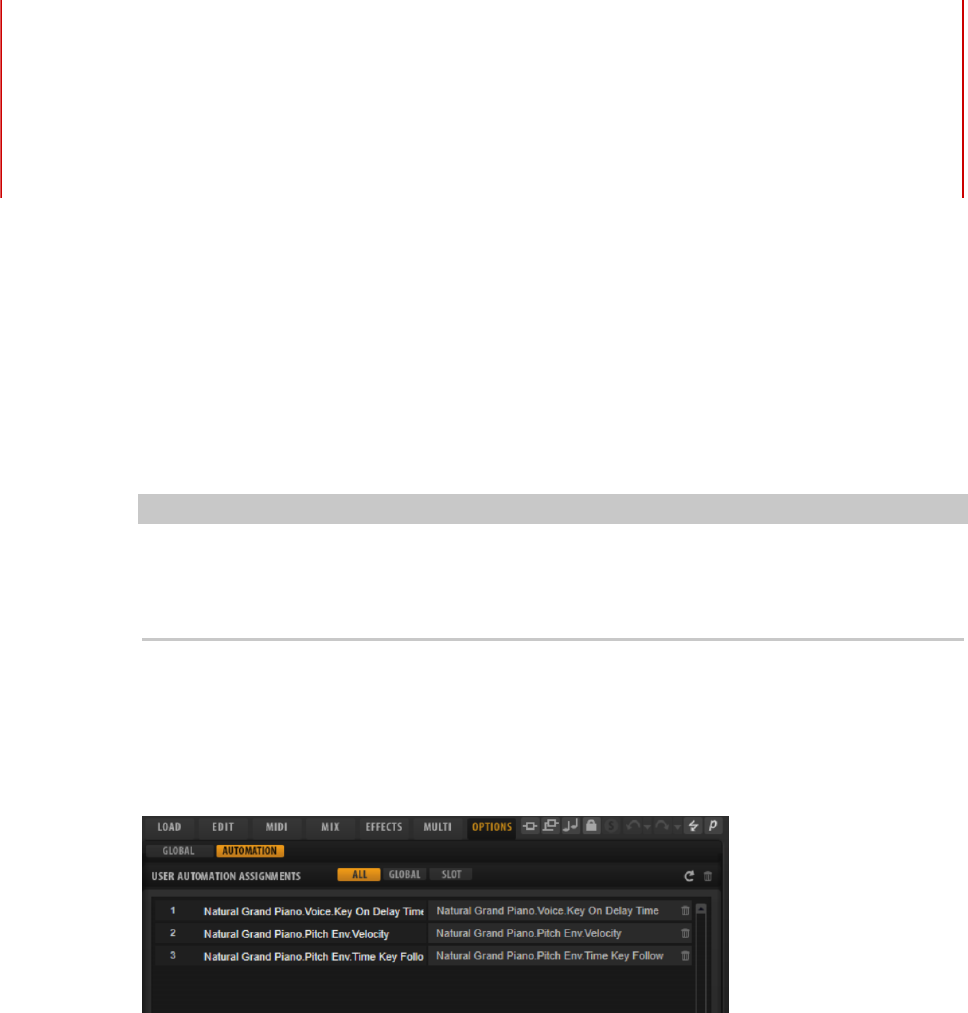
Automation
100
You can automate most of the HALion Sonic parameters from within your host application,
whether these are parameters of a program or global parameters such as AUX effects.
NOTE
• To automate parameters of multiple layers relatively, use quick controls and automate
these instead.
• Not all parameters can be automated.
Automation Page
All assigned automation parameters are shown on the Automation page.
To access this page, open the Options page and activate the Automation tab at the top.
With the tabs at the top, you can specify whether you want to show the automation
parameters for the slot, the global parameters, or all automation parameters.
On the left, the name of the automation parameter is shown, and on the right, the name of
the assigned HALion Sonic parameter. If multiple HALion Sonic parameters are assigned to
one automation parameter, these are listed below each other on the right.
• To remove an automation parameter, click the trash icon to the right of the parameter
name.
• To remove all automation parameters, click Delete All Parameters at the top of the
page.
• To rename an automation parameter, double-click the parameter name and enter the
new name. This name is then used in your host application.
Setting Up Automation

Automation
Setting Up Automation
101
Creating Automation Parameters
• To assign a parameter to an automation parameter, right-click the parameter control
and select Assign to New Automation. The automation parameter is created on the
first free automation parameter.
• To add a parameter to an existing automation parameter, right-click the control, select
Add to Automation and select the automation parameter.
• To remove a parameter from the automation, right-click an automated control and
select Forget Automation.
• To assign a parameter to an automation parameter automatically while working in
your host application, activate Automation Read/Write, start playback, and use the
controls on the HALion Sonic interface.
NOTE
If you have assigned automation parameters for a program and then load another program
into this slot, it can become necessary to verify the automation settings.
If the new program has the same structure as the previous program, for example if you
exchange a Voltage preset with another Voltage preset, HALion Sonic reconnects the
automation parameters correctly and no manual modifications are necessary. However, if
you load a preset with a different structure, for example a Model C preset, the automation
parameters cannot be reconnected. In this case, the disconnected automation parameters
are still displayed in the automation list.
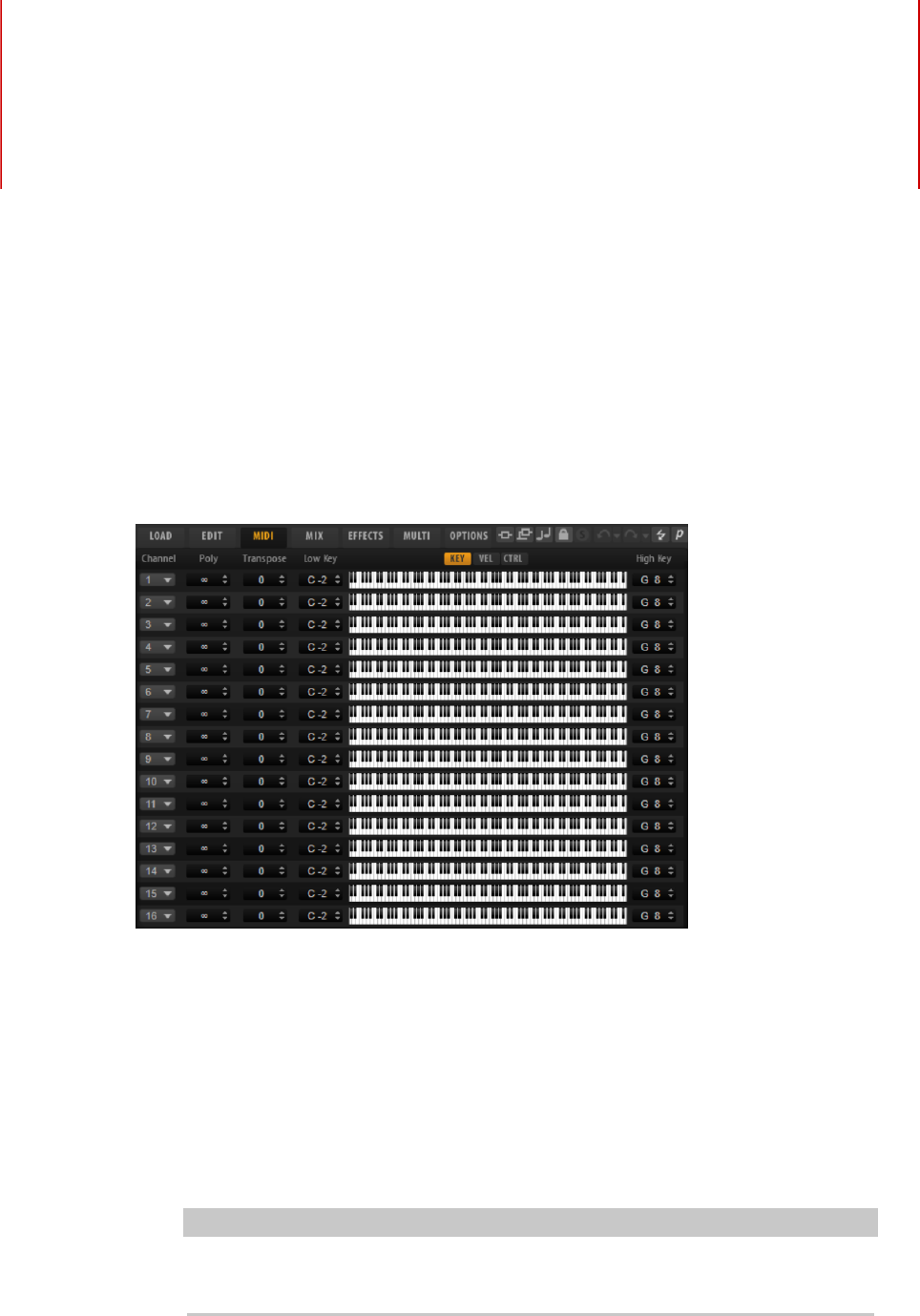
MIDI Editing and Controllers
102
MIDI Page
The MIDI page gives you access to the MIDI slot parameters of HALion Sonic.
Parameters
Channel
The slot receives MIDI signals on the MIDI port and channel that are specified
here. You can set multiple slots to the same MIDI channel and trigger them
simultaneously with the same note events.
Polyphony
Specifies how many notes can be played at the same time.
NOTE
Programs can contain various layers, therefore, the resulting number of voices
can be much higher than the value that is specified here.
Transpose
Allows you to shift the incoming MIDI notes by ±64 semitones before they are sent
to the loaded program.

MIDI Editing and Controllers
MIDI Controllers
103
Key Range (Low Key, High Key)
Allows you to limit the key range for a slot.
Velocity Range (Low Vel, High Vel)
Allows you to limit the velocity range for a slot.
Controller Filter
Allows you to filter out the most commonly used MIDI controllers.
MIDI Controllers
You can assign the parameters volume, pan, mute, solo, send FX 1–4, and the quick controls
of each slot to a MIDI controller. In addition to the slot parameters, you can also assign the
parameters of the AUX FX and most of the edit parameters.
By default, volume, pan, send FX 1–4, and the program quick controls are already assigned.
You can customize this factory MIDI controller mapping by assigning your own MIDI
controllers. This way, you can adapt the mapping to your MIDI keyboard or controller.
To provide more control, you can set the minimum and maximum range for each assignment
separately.
Assigning MIDI Controllers
To assign a MIDI controller to a parameter, proceed as follows:
PROCEDURE
1. Right-click the control that you want to control remotely and select Learn CC.
2. On your MIDI keyboard or controller, use the potentiometer, fader, or button.
The next time you right-click the control, the menu shows the assigned MIDI
controller.
NOTE
You can assign the same MIDI controller several times to different parameters.
However, you cannot assign different MIDI controllers to the same parameter.
RELATED LINKS
MIDI Controller Section on page 30
Unassigning MIDI Controllers
PROCEDURE
•To remove a MIDI controller assignment, right-click the control and select Forget CC.
Restoring the Factory MIDI Controller Assignment
To restore the factory MIDI controller assignments, open the Options page and click Reset to
Factory in the MIDI Controller section.

MIDI Editing and Controllers
MIDI Controllers
104
Setting the Parameter Range
You can set the minimum and maximum values for the parameter for each assignment
separately. This gives you more control over the parameter, for example, when you are
performing live on stage.
PROCEDURE
1. Set the parameter to the minimum value.
2. Right-click the control and select Set Minimum from the context menu.
3. Set the parameter to the maximum value.
4. Right-click the control and select Set Maximum.
MIDI Controllers and AUX FX
You can assign the parameters of the AUX FX to MIDI controllers.
Unlike the slots, the AUX FX do not have a MIDI port and channel of their own. Instead, they
listen to any incoming MIDI controller message, regardless of the MIDI channel. Therefore, if
you assign a parameter to a MIDI controller, you should use a controller number that is not
already in use by any of the assignments that you made for the slots.
NOTE
If you unload or replace the effect, the MIDI controller assignment of this effect is lost.
Saving a MIDI Controller Mapping as Default
After customizing the factory MIDI controller assignments, you can save them as default.
PROCEDURE
•Open the Options Editor and, in the MIDI Controller section, click Save as Default.
RESULT
Now, each time that you load a new instance of the plug-in, your customized MIDI controller
mapping is available as default.
NOTE
• Saving the controller mapping as default does not include the MIDI controller
assignments of the AUX FX.
• The MIDI controller mapping is saved with each project. This way, you can transfer your
settings to other systems. The project also includes the MIDI controller assignments of
the AUX FX.

MIDI Editing and Controllers
MIDI Controllers
105
Automation and Factory MIDI Controller Assignment
Several parameters on the plug-in interface are available for automation from your host
software and can be assigned to an external MIDI controller.
The table shows the controller numbers and names of the default factory MIDI controller
assignment. The assigned MIDI controller numbers are the same for all slots. However, the
MIDI controllers listen only to the MIDI channels of the corresponding slot.
Parameter Controller Number Name
Volume #7 Volume
Pan #10 Pan
Send FX 1 #91 Effect 1 Depth
Send FX 2 #92 Effect 2 Depth
Send FX 3 #93 Effect 3 Depth
Send FX 4 #94 Effect 4 Depth
Program QC 1 #74 Brightness
Program QC 2 #71 Harmonic Content
Program QC 3 #73 Attack Time
Program QC 4 #72 Release Time
Program QC 5 #75 Sound Controller #6
Program QC 6 #76 Sound Controller #7
Program QC 7 #77 Sound Controller #8
Program QC 8 #78 Sound Controller #9
NOTE
•Send FX 1-4 are only available if the corresponding AUX send effects are loaded.
•You can remotely control any other parameter by assigning the parameter first to a
quick control and then to a MIDI controller.
•You can use MIDI controllers inside the modulation matrix of a synth or sample layer to
control the cutoff, for example.
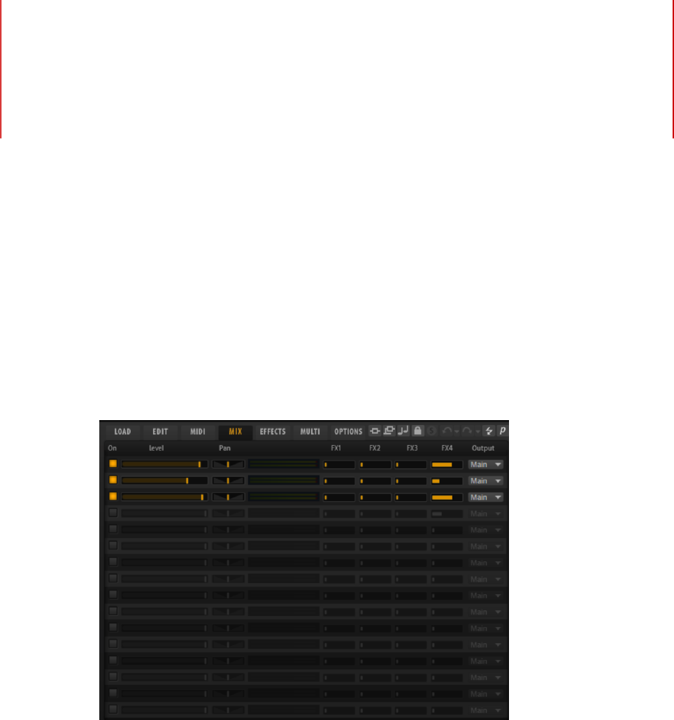
Mixing and Effect Handling
106
Mix Page
The Mix page gives you access to the audio parameters of HALion Sonic. This comprises the
level and pan settings, as well as the AUX effect sends and the output selector. To monitor
the output levels, each slot also features a level meter.
Mix Page Parameters
On
Activates/Deactivates MIDI input of the slot. If you deactivate a slot, its MIDI
communication is interrupted and sounds are no longer processed in the
background.
Level
Sets the output level of the slot.
Pan
Sets the position in the stereo panorama.
Meter
Indicates the output level of the slot.
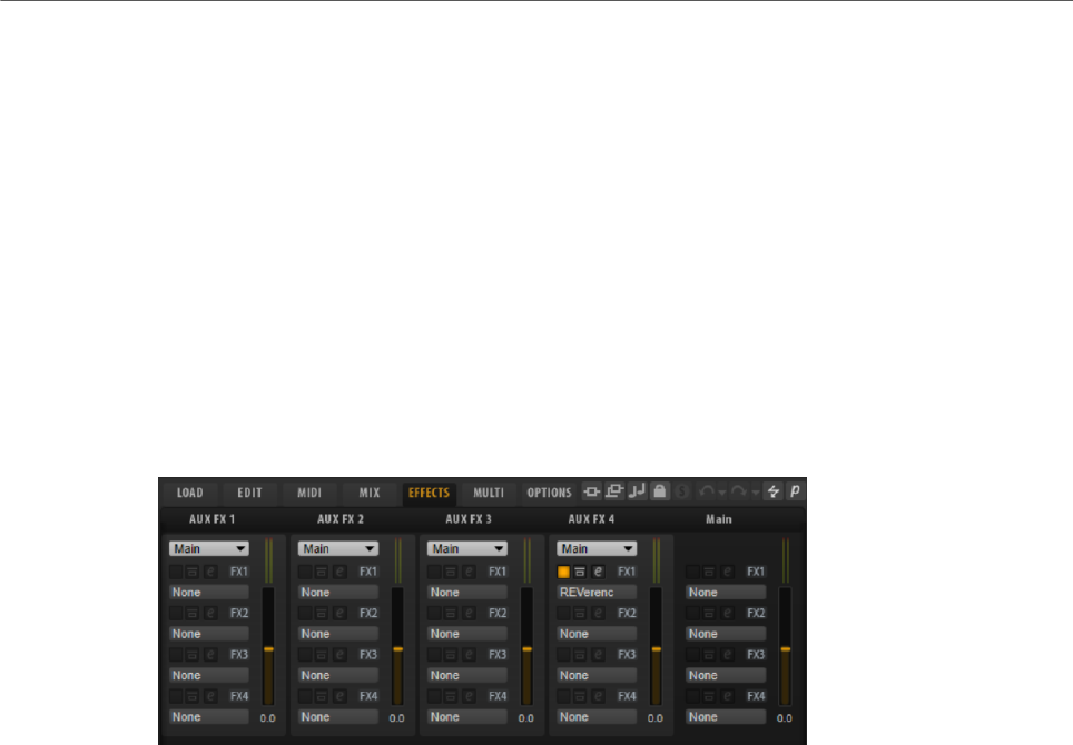
Mixing and Effect Handling
Effect Handling
107
FX 1–4
These controls specify the amount of signal that is sent to the four auxiliary
busses that host up to four effects each.
Output
Specifies to which of the 16 plug-in outputs the slot is routed.
Effect Handling
The busses can be routed to the main plug-in output or to one of the individual outputs.
The Effects page also provides access to the main output bus which also features four
inserts. These can be used to add a global EQ or compressor to the signal chain, for
example.
Default Effect Settings
Each effect comes with factory default settings. However, you can save your own default
settings for each effect as a preset.
• Set up the effect.
• Click the Save Preset button in the title bar of the effect section and save the preset
under the name “--Default--”.
The preset is saved in the presets folder of the effect and is loaded each time you load the
effect.
• To return to the factory default settings, delete your default preset.
Using the Insert Effect Slots
On the Effects page, you can set up insert effects for AUX busses.
•To assign an insert effect, click the effect slot and select the effect from the menu.
•To remove an insert effect including its current settings, click the effect slot and select
None from the menu.
•To deactivate an effect without removing it, click its On/Off button above the slot. This
way, you can switch off the effect without losing its settings.
•To bypass an effect, activate the Bypass button of the slot. Bypass is active when the
button lights up.

Mixing and Effect Handling
Effect Handling
108
•To edit an insert effect, click the e button of the corresponding slot. You can edit only
one effect at a time. The parameters of the insert effect are displayed in the bottom
section.
•To move an effect to another slot, click its drag icon and drag it to another slot. This
replaces any effect loaded in this slot.
•To change the order of the effects, drag them by their drag icon to a new position
between two slots.
•To copy an effect into another slot, Alt-click the drag icon and drag it onto the new slot.
This replaces any effect loaded in this slot.
NOTE
You can also copy effects between the different mixers. First drag an effect to the
corresponding mixer tab. Then drag it to the position where you want to insert it.
•To copy an effect and insert it between two effect slots, Alt-click its drag icon and drag
it between two slots.
NOTE
You can also copy effects between the different mixers. First drag an effect to the
corresponding mixer tab. Then drag it to the position where you want to insert it.
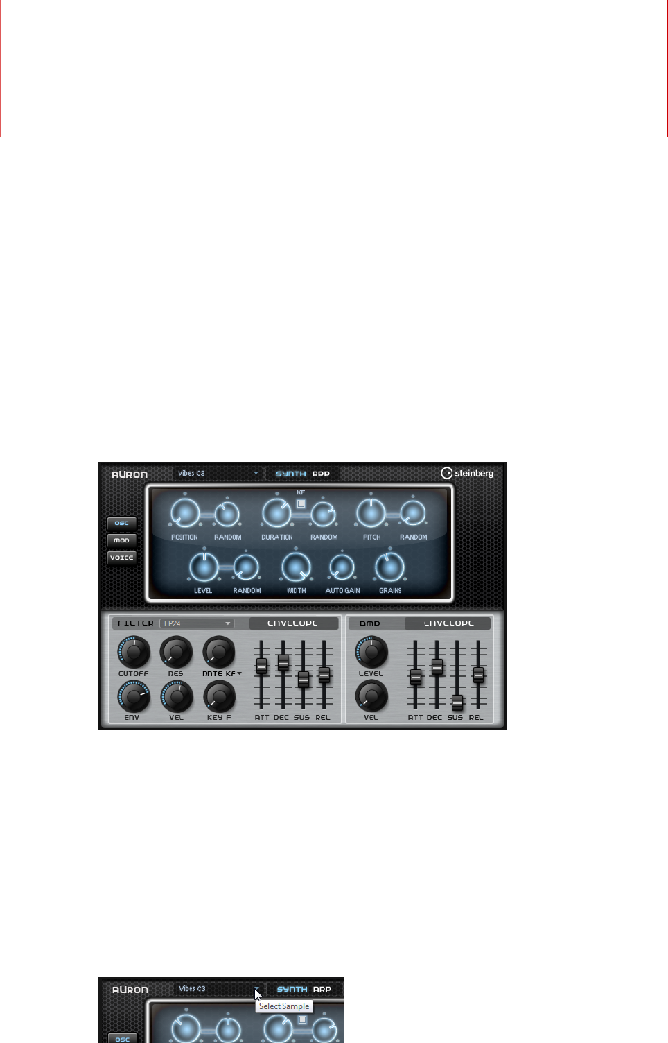
Included Instruments
109
HALion Sonic comes with a factory library containing powerful instruments. For each
instrument, an intuitive macro page is available, offering a rich palette of presets.
Auron
The Auron synth uses granular synthesis with up to 8 grain streams to produce oscillator
waveforms. With the integrated arpeggiator and step sequencer, you can create anything
from sequencer lines to stepped chords.
The granular oscillator is followed by a multi-mode filter that offers a large number of
different filter shapes. The filter can be modulated by modulation sources like the keyboard,
velocity, and LFO, but also by the controller lanes of the step sequencer, for example.
Auron includes 2 LFOs for pitch, grain position, formant, and duration as well as filter
modulations. The first LFO can be synchronized to the tempo of the host application and
allows for modulations of grain position, formant and duration, as well as filter cutoff. The
second LFO is controlled by the modulation wheel and is used to create a vibrato.
For the grain synthesizer, three pages are available: Osc, Mod, and Voice. To open a page,
click the corresponding button in the upper left of the Auron panel.
Selecting Samples

Included Instruments
Auron
110
You can select samples on the sample selector that is opened by clicking the little triangle in
the upper left of the page.
Osc Page
On this page, you can make settings for the grain oscillator.
Position
You can set the playback position of the grains manually. For example, at a
setting of 50 %, the playback position is in the middle of the sample. The playback
position is updated with every new grain.
Random Position
Selects a random playback position within a specific range around the current
position. At a setting of 100 %, the playback position jumps to a random position
between the start and the end of the sample.
Duration
Increases the grain period by a factor ranging from 1 to 1000.
For very short grains, the sound gets the pitch of the frequency at which the
grains repeat. For grains longer than 30 ms, the sound gets the pitch of the
original sample.
Random Duration
Sets the random grain duration. This duration is calculated at the start of a new
grain.
Duration Key Follow
Determines how the grain duration changes with the notes you play. It is mostly
used with short durations. Longer durations sound with the original pitch of the
sample and therefore do not need to follow the keyboard.
Pitch
Allows you to specify an interval between -12 and +12 semitones. The grains are
played randomly at their original pitch, or are transposed according to the pitch
interval. This parameter is suited for longer grain durations.
Random Pitch
Sets the random pitch range in semitones and cents. At a setting of +12, the
random pitch values lie between -12 and +12 semitones. This parameter can be
used to enrich the sound.
Level
Adjusts the overall level of the grain oscillator. When you increase the number
of grains, it might become necessary to lower the oscillator level. When you play
back a very quiet portion of a sample, you can use this control to raise the level.
Random Level
Sets a random level for each new grain. At a setting of 100 %, the level varies
between a factor of 0 and 2 of the original level.
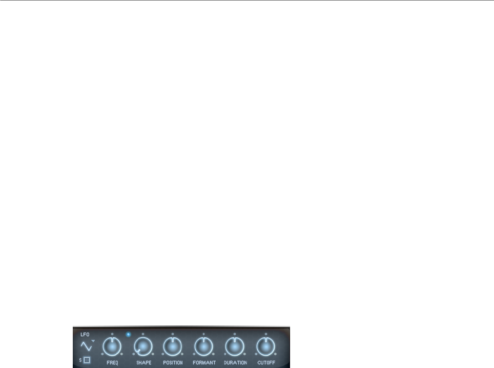
Included Instruments
Auron
111
Width
Narrows the stereo width of the grain oscillator. It is applied after the grain
oscillator and does not affect the stereo width of the actual sample. At a setting
of 0 %, the output of the grain oscillator is monophonic.
Auto Gain
Allows you to automatically adjust the level of grains using quieter sample parts.
This way, you get a more homogeneous signal and you can use a quiet part of a
sample as source.
Grains
Allows you to specify the number of grains, from 1 to 8. For example, with a
setting of 4, you get 4 grains per period of the grain duration.
To hear the effect of this setting, you have to play a new note.
Mod Page
The Mod page contains the LFO settings in the upper section and the mod wheel, or vibrato,
settings in the lower section.
LFO Settings
LFO Waveform and Shape
•Sine produces smooth modulation, suitable for vibrato or tremolo. Shape
adds additional harmonics to the waveform.
•Triangle is similar to Sine. Shape continuously changes the triangle
waveform to a trapezoid.
•Saw produces a ramp cycle. Shape continuously changes the waveform
from ramp down to triangle to ramp up.
•Pulse produces stepped modulation, where the modulation switches
abruptly between two values. Shape continuously changes the ratio
between the high and low state of the waveform. If Shape is set to 50 %, a
square wave is produced.
•Ramp is similar to the Saw waveform. Shape increasingly puts silence
before the sawtooth ramp up begins.
•Log produces a logarithmic modulation. Shape continuously changes the
logarithmic curvature from negative to positive.
•S & H 1 produces randomly stepped modulation, where each step is
different. Shape puts ramps between the steps and changes the S & H into
a smooth random signal when fully turned right.
•S & H 2 is similar to S & H 1. The steps alternate between random high and
low values. Shape puts ramps between the steps and changes the S & H
into a smooth random signal when fully turned right.
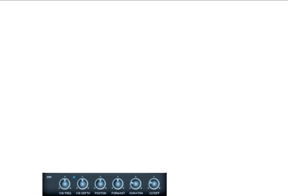
Included Instruments
Auron
112
Freq
Controls the frequency of the modulation, that is, the speed of the LFO.
Sync
If Sync is activated, the frequency is set in fractions of beats.
Position
Controls the modulation depth of the grain position modulation.
Formant
Controls the modulation depth of the grain formant modulation.
Duration
Controls the modulation depth of the grain duration modulation.
Cutoff
Controls the modulation depth of the filter cutoff modulation.
Mod Wheel Settings
Vib Freq
Controls the frequency of the second LFO that is used for pitch modulation
(vibrato).
Vib Depth
Controls the depth of the pitch modulation (vibrato).
Position
Controls the influence of the mod wheel on the grain position.
Formant
Controls the influence of the mod wheel on the grain formant.
Duration
Controls the influence of the mod wheel on the grain duration.
Cutoff
Controls the influence of the mod wheel on the filter cutoff.

Included Instruments
Auron
113
Voice Page
Polyphony
If Mono mode is deactivated, you can use this parameter to specify how many
notes can be played simultaneously.
Octave
Adjusts the pitch in octave steps.
Coarse
Adjusts the pitch in semitone steps.
Fine
Allows you to fine-tune the pitch in cent steps.
Fixed Pitch
Activate this option if you do not want the sample to be transposed over the
keyboard. If you work with short grain durations and Duration Key Follow is
activated on the Osc page, the pitch of the played key still follows the keyboard,
and only the frequency response changes.
Pitchbend Up/Pitchbend Down
Determines the range for the modulation that is applied when you move the
pitchbend wheel.
Glide
Allows you to bend the pitch between notes that follow each other. You achieve
the best results in Mono mode.
Glide Time
Sets the glide time, that is, the time it takes to bend the pitch from one note to
the next.
Fingered
Activate this parameter to glide the pitch only between notes that are played
legato.
Mono
Activates monophonic playback.
Retrigger
If this option is activated, a note that was stolen is retriggered if you still hold the
stolen note when releasing the newer note. This lets you play trills by holding

Included Instruments
Auron
114
one note and quickly and repeatedly pressing and releasing another note, for
example.
Trigger Mode
Defines the trigger behavior for new notes.
•Normal triggers a new note when the previous note gets stolen. The
sample and the envelope of the new note are triggered from the start.
To minimize discontinuities, use the Fade Out parameter of the zone.
•Resume does not always trigger a new note.
If the new note stays within the same zone, the envelope is retriggered, but
resumes at the level of the stolen note. The pitch of the zone is set to the
new note.
If the new note plays in a different zone, the sample and the envelope of the
new note are triggered from the start.
•Legato does not always trigger a new note.
If the new note stays within the same zone, the envelope keeps running.
The pitch of the zone is set to the new note.
If the new note plays in a different zone, the sample and the envelope of the
new note are triggered from the start.
•Resume Keeps Zone does not trigger a new note upon note stealing. The
envelope resumes at the level of the stolen note and the pitch of the zone is
set to the new note, even if the new note plays in a different zone.
•Legato Keeps Zone does not trigger a new note upon note stealing. The
envelope keeps running and the pitch of the zone is set to the new note,
even if the new note plays in a different zone.
Filter Section
Filter Shape
• LP24, 18, 12, and 6 are low-pass filters with 24, 18, 12, and 6 dB/oct.
Frequencies above the cutoff are attenuated.
• BP12 and BP24 are band-pass filters with 12 and 24 dB/oct. Frequencies
below and above the cutoff are attenuated.
• HP6+LP18 and HP6+LP12 are combinations of a high-pass filter with 6 dB/
oct and a low-pass filter with 18 and 12 dB/oct, respectively (asymmetric
band-pass filter). Frequencies below and above the cutoff are attenuated.
Attenuation is more pronounced for the frequencies above the cutoff.
• HP12+LP6 and HP18+LP6 are combinations of a high-pass filter with 12
and 18 dB/oct and a low-pass filter with 6 dB/oct (asymmetric band-pass
filter). Frequencies below and above the cutoff are attenuated. Attenuation
is more pronounced for the frequencies below the cutoff.
• HP24, 18, 12, and 6 are high-pass filters with 24, 18, 12, and 6 dB/oct.
Frequencies below the cutoff are attenuated.
• BR12 and BR24 are band-reject filters with 12 and 24 dB/oct. Frequencies
around the cutoff are attenuated.

Included Instruments
Auron
115
• BR12+LP6 and BR12+LP12 are combinations of a band-reject filter with 12
dB/oct and a low-pass filter with 6 and 12 dB/oct, respectively. Frequencies
around and above the cutoff are attenuated.
• BP12+BR12 is a band-pass filter with 12 dB/oct plus a band-reject filter
with 12 dB/oct. Frequencies below, above, and around the cutoff are
attenuated.
• HP6+BR12 and HP12+BR12 are combinations of a high-pass filter with 6
and 12 dB/oct and a band-reject filter with 12 dB/oct. Frequencies below
and around the cutoff are attenuated.
• AP is an all-pass filter with 18 dB/oct. Frequencies around the cutoff are
attenuated.
• AP+LP6 is an all-pass filter with 18 dB/oct plus a low-pass filter with 6 dB/
oct. Frequencies around and above the cutoff are attenuated.
• HP6+AP is a high-pass filter with 6 dB/oct plus an all-pass filter with 18
dB/oct. Frequencies around and below the cutoff are attenuated.
Cutoff
Controls the cutoff frequency of the filter.
Resonance
Emphasizes the frequencies around the cutoff. At higher settings, the filter self-
oscillates, which results in a ringing tone.
Distortion
Adds distortion to the signal. The following distortion types are available:
•Tube adds warm, tube-like distortion.
•Hard Clip adds bright, transistor-like distortion.
•Bit Reduction adds digital distortion by means of quantization noise.
•Rate Reduction adds digital distortion by means of aliasing.
•Rate Reduction Key Follow adds digital distortion by means of aliasing, but
with Key Follow. The rate reduction follows the keyboard, so the higher you
play, the higher the sample rate.
Envelope Amount
Controls the cutoff modulation from the filter envelope.
Cutoff Velocity
Controls the cutoff modulation from velocity.
Cutoff Key Follow
Adjusts the cutoff modulation using the note number. Increase this parameter
to raise the cutoff with higher notes. At 100 %, the cutoff follows the played pitch
exactly.
Filter Envelope Section
Attack
Controls the attack time of the filter envelope.
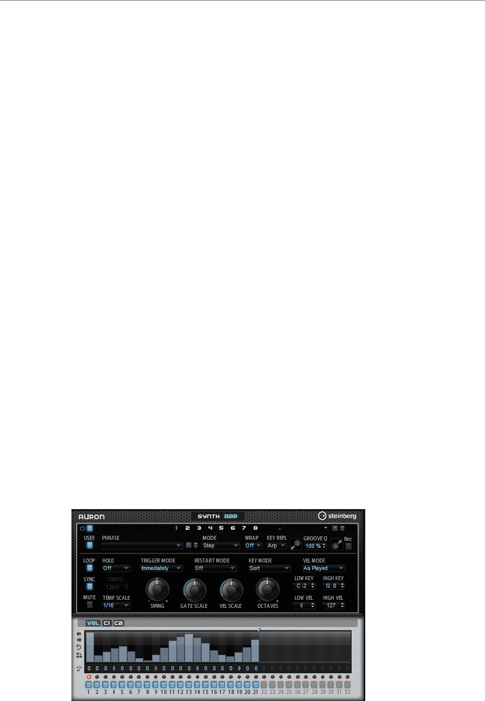
Included Instruments
Auron
116
Decay
Controls the decay time of the filter envelope.
Sustain
Controls the sustain level of the filter envelope.
Release
Controls the release time of the filter envelope.
Amplifier Section
Level
Controls the overall volume of the sound.
Velocity
Controls the level modulation from velocity. At 0, all notes are played with the
same level.
Amplifier Envelope Section
Attack
Controls the attack time of the amplifier envelope.
Decay
Controls the decay time of the amplifier envelope.
Sustain
Controls the sustain level of the amplifier envelope.
Release
Controls the release time of the amplifier envelope.
Arp Page
This page contains the same parameters as the FlexPhraser.
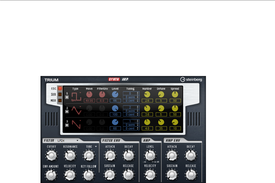
Included Instruments
Trium
117
RELATED LINKS
FlexPhraser on page 76
Trium
Trium was designed to create modern and rich sounds. It comes with 3 oscillators, a sub
oscillator, a ring modulator, and a noise generator. With the integrated arpeggiator and step
sequencer, you can create anything from sequencer lines to stepped chords.
The oscillators are followed by a multi-mode filter that offers a large number of different
filter shapes. The filter can be modulated using modulation sources like the keyboard,
velocity, and LFO, but also by the controller lanes of the step sequencer, for example.
Trium includes two LFOs for pitch, PWM, and filter modulations. The first LFO can be
synchronized to the tempo of the host application and allows for filter cutoff, pitch, and
waveform modulation of the three main oscillators. The second LFO is controlled by the
modulation wheel and is used to create a vibrato.
Osc Page
The Osc page contains the parameters for the three main oscillators.
• To activate an oscillator, click its On/Off button.
OSC 1/2/3 Type
The oscillator type defines the basic sound character of the oscillator. This pop-
up menu lists the waveforms (sine, triangle, saw, or square), followed by the
algorithm (PWM, Sync, CM, or XOR). The combination of waveform and algorithm
controls the sound of the oscillator.
The following algorithms are available:
•PWM (pulse width modulation) is only supported by the square waveform.
The Waveform parameter sets the ratio between the high and low value
of the square wave. A setting of 50 % produces a pure square wave. With
settings below or above 50 %, the oscillator produces rectangular waves.
•Sync provides different hard-sync oscillators, where each is a combination
of a master and slave oscillator. The wave shape of the slave oscillator

Included Instruments
Trium
118
(sine, triangle, saw, or square) is reset with each full wave cycle of the
master oscillator. This means that a single oscillator can produce a
rich sync-sound without using other oscillators as slave or master. The
Waveform parameter adjusts the pitch of the slave oscillator, producing the
typical sync sound.
•CM (cross modulation) provides a combination of two oscillators where
a master oscillator is modulating the pitch of a slave oscillator (sine,
triangle, saw, or square) at the rate of the audio sample. The Waveform
parameter adjusts the pitch ratio between slave and master oscillator,
resulting in a sound close to frequency modulation.
•XOR (exclusive OR) compares two square waveforms with an XOR
operation. Depending on the outcome of the XOR operation, the waveform
shape of a third oscillator (sine, triangle, saw, or square) is reset. The
Waveform parameter adjusts the pitch ratio of the square oscillators
resulting in a sound close to ring modulation of the third oscillator.
Level
Adjusts the output level of the oscillator.
Waveform
Modifies the sound of the oscillator algorithm. Its effect depends on the selected
oscillator type.
NOTE
This parameter is only available for oscillator types that allow waveform
modulation.
Filter Envelope
Determines how much the modulation of the filter envelope influences the
oscillator waveform.
NOTE
This parameter is only available for oscillator types that allow waveform
modulation.
Tuning
These parameters allow you to adjust the pitch in octave, semitone, and cent
steps.
Multi Oscillator Number, Detune, and Spread
Each of the main oscillators offers these multi-oscillator functions. They allow
you to create a richer sound by producing up to eight oscillators simultaneously.
•Number determines the number of oscillators that play back
simultaneously. You can also set fractions of numbers. For example, with
a setting of 2.5, you hear two oscillators at full level and a third one at half
level.
•Detune detunes the oscillators.
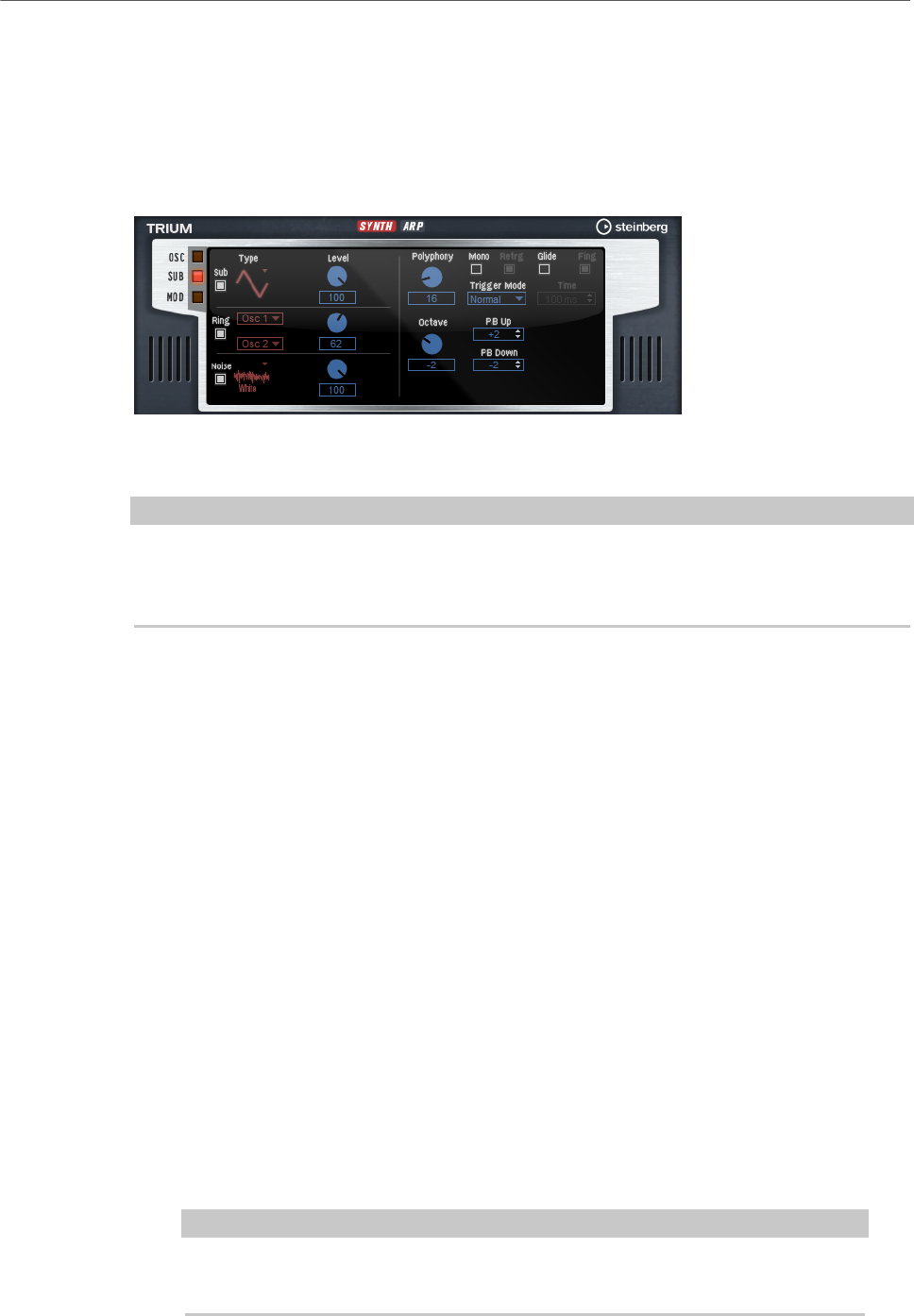
Included Instruments
Trium
119
•Spread narrows or widens the stereo panorama. With a setting of 0 %, you
create a mono signal, and with 100 %, you create a stereo signal.
Sub Page
The Sub page contains the parameters for the sub oscillator, the ring modulator, and the
noise generator.
Activate the sub oscillator, the ring modulator, and the noise generator by clicking their On/
Off buttons.
NOTE
Deactivate the sub oscillator, the ring modulator, and the noise generator if they are not
needed, because they use CPU cycles even if they are not heard, such as in a situation where
the level is set to 0 %.
Sub Oscillator
The pitch of the sub oscillator is always one octave lower than the overall pitch. The overall
pitch is determined by the Octave setting.
On/Off
Activates/Deactivates the sub oscillator.
Type
The wave shape of the sub oscillator. You can choose between Sine, Triangle,
Saw, Square, Pulse Wide, and Pulse Narrow.
Level
Adjusts the output level of the sub oscillator.
Ring Modulator
Ring modulation produces sums and differences between the frequencies of two signals.
Ring Modulation Source 1/Ring Modulation Source 2
Determines the sources to be ring modulated. You can select OSC 1 or Sub as
Source 1, and OSC 2 or OSC 3 as Source 2.
NOTE
Make sure that the corresponding oscillators are activated when you select them.
Otherwise, no sound is heard.

Included Instruments
Trium
120
Ring Modulation Level
Adjusts the output level of the ring modulation.
Noise Generator
The Noise parameter is used for non-pitched sounds. In addition to standard white and pink
noise, there are also band-pass filtered versions of white and pink noise.
Noise Type
The sound color of the noise. You can choose between standard and band-pass
filtered (BPF) versions of white and pink noise.
Noise Level
Adjusts the output level of the noise generator.
Voice Parameters
On the right, the voice parameters are available.
Polyphony
If Mono mode is deactivated, you can use this parameter to specify how many
notes can be played simultaneously.
Octave
Adjusts the pitch in octave steps.
Pitchbend Up/Pitchbend Down
Determines the range for the modulation that is applied when you move the
pitchbend wheel.
Glide
Allows you to bend the pitch between notes that follow each other. You achieve
the best results in Mono mode.
Glide Time
Sets the glide time, that is, the time it takes to bend the pitch from one note to
the next.
Fingered
Activate this parameter to glide the pitch only between notes that are played
legato.
Mono
Activates monophonic playback.
Retrigger
If this option is activated, a note that was stolen is retriggered if you still hold the
stolen note when releasing the newer note. This lets you play trills by holding
one note and quickly and repeatedly pressing and releasing another note, for
example.
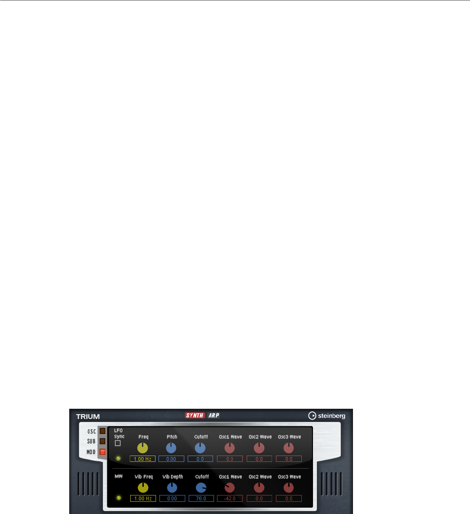
Included Instruments
Trium
121
Trigger Mode
Defines the trigger behavior for new notes.
•Normal triggers a new note when the previous note gets stolen. The
sample and the envelope of the new note are triggered from the start.
To minimize discontinuities, use the Fade Out parameter of the zone.
•Resume does not always trigger a new note.
If the new note stays within the same zone, the envelope is retriggered, but
resumes at the level of the stolen note. The pitch of the zone is set to the
new note.
If the new note plays in a different zone, the sample and the envelope of the
new note are triggered from the start.
•Legato does not always trigger a new note.
If the new note stays within the same zone, the envelope keeps running.
The pitch of the zone is set to the new note.
If the new note plays in a different zone, the sample and the envelope of the
new note are triggered from the start.
•Resume Keeps Zone does not trigger a new note upon note stealing. The
envelope resumes at the level of the stolen note and the pitch of the zone is
set to the new note, even if the new note plays in a different zone.
•Legato Keeps Zone does not trigger a new note upon note stealing. The
envelope keeps running and the pitch of the zone is set to the new note,
even if the new note plays in a different zone.
Mod Page
The Mod page contains the LFO settings in the upper section and the mod wheel, or vibrato,
settings in the lower section.
LFO Settings
Sync
If Sync is activated, the frequency is set in fractions of beats.
Freq
Controls the frequency of the modulation, that is, the speed of the LFO.
Pitch
Controls the modulation depth of the pitch modulation.

Included Instruments
Trium
122
Cutoff
Controls the modulation depth of the filter cutoff modulation.
Osc1/2/3 Wave
These parameters control the modulation depth of the waveform modulation of
the three main oscillators.
NOTE
These controls are only available if the selected oscillator type supports
waveform modulation.
Mod Wheel Settings
Vib Freq
Controls the frequency of the second LFO that is used for pitch modulation
(vibrato).
Vib Depth
Controls the depth of the pitch modulation (vibrato).
Cutoff
Controls the influence of the mod wheel on the filter cutoff.
Osc1/2/3 Wave
These parameters control the influence of the mod wheel on the waveform of the
three main oscillators.
NOTE
These controls are only available if the selected oscillator type supports
waveform modulation.
Filter Section
Filter Shape
• LP24, 18, 12, and 6 are low-pass filters with 24, 18, 12, and 6 dB/oct.
Frequencies above the cutoff are attenuated.
• BP12 and BP24 are band-pass filters with 12 and 24 dB/oct. Frequencies
below and above the cutoff are attenuated.
• HP6+LP18 and HP6+LP12 are combinations of a high-pass filter with 6 dB/
oct and a low-pass filter with 18 and 12 dB/oct, respectively (asymmetric
band-pass filter). Frequencies below and above the cutoff are attenuated.
Attenuation is more pronounced for the frequencies above the cutoff.
• HP12+LP6 and HP18+LP6 are combinations of a high-pass filter with 12
and 18 dB/oct and a low-pass filter with 6 dB/oct (asymmetric band-pass
filter). Frequencies below and above the cutoff are attenuated. Attenuation
is more pronounced for the frequencies below the cutoff.

Included Instruments
Trium
123
• HP24, 18, 12, and 6 are high-pass filters with 24, 18, 12, and 6 dB/oct.
Frequencies below the cutoff are attenuated.
• BR12 and BR24 are band-reject filters with 12 and 24 dB/oct. Frequencies
around the cutoff are attenuated.
• BR12+LP6 and BR12+LP12 are combinations of a band-reject filter with 12
dB/oct and a low-pass filter with 6 and 12 dB/oct, respectively. Frequencies
around and above the cutoff are attenuated.
• BP12+BR12 is a band-pass filter with 12 dB/oct plus a band-reject filter
with 12 dB/oct. Frequencies below, above, and around the cutoff are
attenuated.
• HP6+BR12 and HP12+BR12 are combinations of a high-pass filter with 6
and 12 dB/oct and a band-reject filter with 12 dB/oct. Frequencies below
and around the cutoff are attenuated.
• AP is an all-pass filter with 18 dB/oct. Frequencies around the cutoff are
attenuated.
• AP+LP6 is an all-pass filter with 18 dB/oct plus a low-pass filter with 6 dB/
oct. Frequencies around and above the cutoff are attenuated.
• HP6+AP is a high-pass filter with 6 dB/oct plus an all-pass filter with 18
dB/oct. Frequencies around and below the cutoff are attenuated.
Cutoff
Controls the cutoff frequency of the filter.
Resonance
Sets the filter resonance.
Distortion
Adds distortion to the signal. The following distortion types are available:
•Tube adds warm, tube-like distortion.
•Hard Clip adds bright, transistor-like distortion.
•Bit Reduction adds digital distortion by means of quantization noise.
•Rate Reduction adds digital distortion by means of aliasing.
•Rate Reduction Key Follow adds digital distortion by means of aliasing, but
with Key Follow. The rate reduction follows the keyboard, so the higher you
play, the higher the sample rate.
Envelope Amount
Controls the cutoff modulation from the filter envelope.
Cutoff Velocity
Controls the cutoff modulation from velocity.
Cutoff Key Follow
Adjusts the cutoff modulation using the note number. Increase this parameter
to raise the cutoff with higher notes. At 100 %, the cutoff follows the played pitch
exactly.

Included Instruments
Trium
124
Filter Envelope Section
Attack
Controls the attack time of the filter envelope.
Decay
Controls the decay time of the filter envelope.
Sustain
Controls the sustain level of the filter envelope.
Release
Controls the release time of the filter envelope.
Amplifier Section
Level
Controls the overall volume of the sound.
Velocity
Controls the level modulation from velocity. At 0, all notes are played with the
same level.
Amplifier Envelope Section
Attack
Controls the attack time of the amplifier envelope.
Decay
Controls the decay time of the amplifier envelope.
Sustain
Controls the sustain level of the amplifier envelope.
Release
Controls the release time of the amplifier envelope.
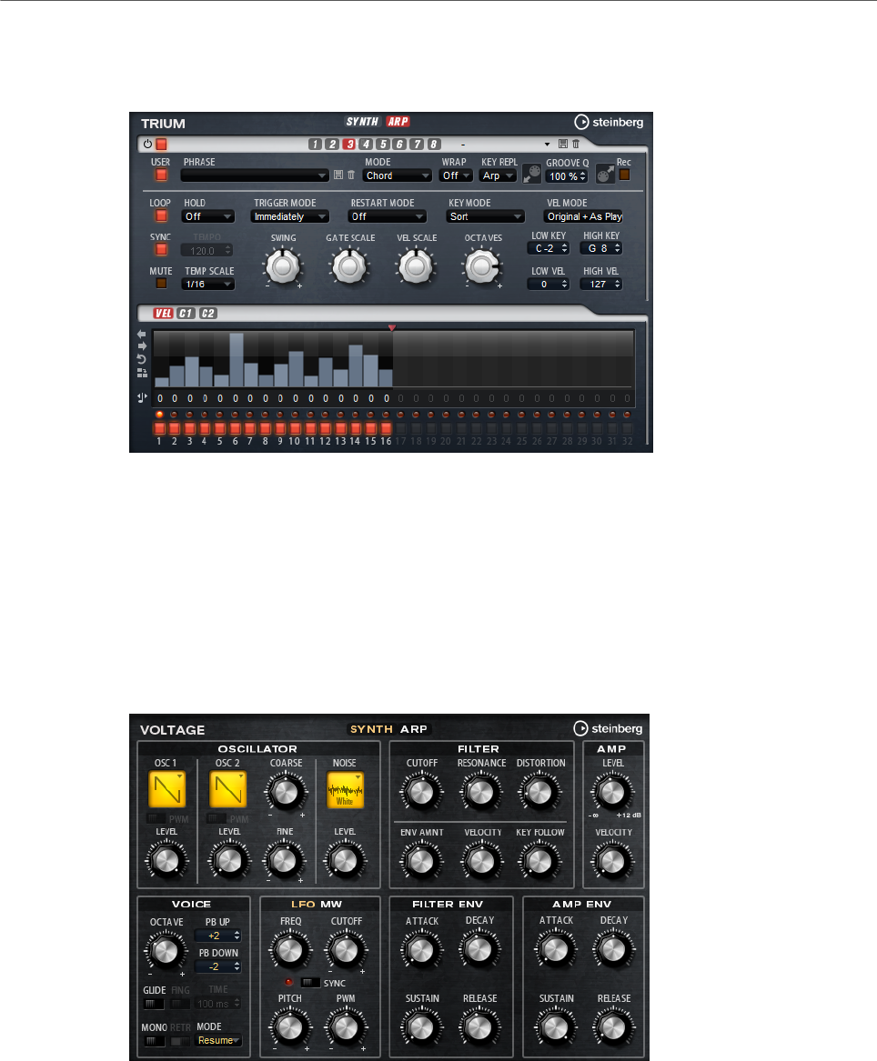
Included Instruments
Voltage
125
Arp Page
This page contains the same parameters as the FlexPhraser.
RELATED LINKS
FlexPhraser on page 76
Voltage
Voltage is a two-oscillator and noise synthesizer that can be used for synth basses, but it
also allows you to create any kind of classic monophonic and polyphonic synth sound. With
the integrated arpeggiator and step sequencer, you can create anything from sequencer lines
to stepped chords.
The two oscillators and the noise generator are followed by a 24 dB low-pass filter. The filter
can be modulated using modulation sources like the keyboard, velocity, and LFO, but also by
the controller lanes of the step sequencer, for example. Voltage includes 2 LFOs for pitch,
PWM, and filter modulations. The first LFO can be synchronized to the tempo of the host
application and allows for filter and pitch modulation. The second LFO is controlled by the
modulation wheel and is used to create a vibrato.
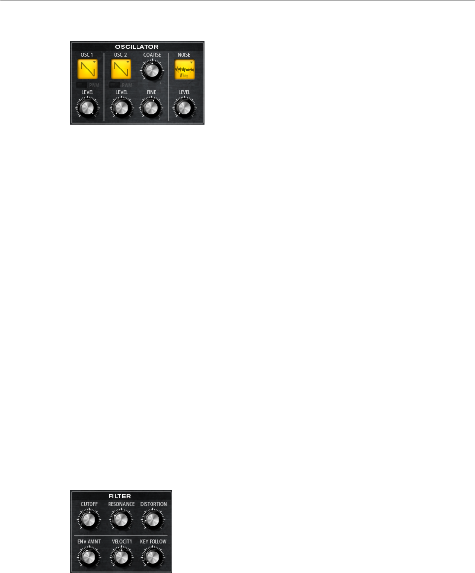
Included Instruments
Voltage
126
Oscillator Section
Oscillator 1/2 Waveform
Sets the waveform for the oscillator. You can choose between saw, triangle, and
square.
Oscillator 1/2 Level
Controls the level of the oscillators.
PWM
PWM (pulse width modulation) is only available for the square waveform. Activate
this option if you want to be able to let the LFO modulate the width of the wave.
Osc 2 Coarse
Detunes the second oscillator by +/-12 semitones.
Osc 2 Fine
Detunes the second oscillator by +/- 100 cents.
Noise Type
The sound color of the noise. You can choose between standard and band-pass
filtered (BPF) versions of white and pink noise.
Level
Controls the level of the noise generator.
Filter Section
Cutoff
Controls the cutoff frequency of the filter.
Resonance
Emphasizes the frequencies around the cutoff. At higher settings, the filter self-
oscillates, which results in a ringing tone.
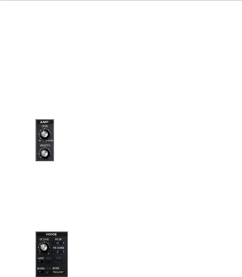
Included Instruments
Voltage
127
Distortion
Adds tube-like distortion to the signal.
Envelope Amount
Controls the cutoff modulation from the filter envelope.
Cutoff Velocity
Controls the cutoff modulation from velocity.
Cutoff Key Follow
Adjusts the cutoff modulation using the note number. Increase this parameter
to raise the cutoff with higher notes. At 100 %, the cutoff follows the played pitch
exactly.
Amplifier Section
Level
Controls the overall volume of the sound.
Velocity
Controls the level modulation from velocity. At 0, all notes are played with the
same level.
Voice Section
Octave
Adjusts the pitch in octave steps.
Pitchbend Up/Pitchbend Down
Determines the range for the modulation that is applied when you move the
pitchbend wheel.

Included Instruments
Voltage
128
Glide
Allows you to bend the pitch between notes that follow each other. You achieve
the best results in Mono mode.
Fingered
Activate this parameter to glide the pitch only between notes that are played
legato.
Mono
Activates monophonic playback.
Retrigger
This option is only available in Mono mode. If Retrigger is activated, a note that
was stolen by another note is retriggered if you still hold the stolen note when
you release the new one.
This way, you can play trills by holding one note and quickly and repeatedly
pressing and releasing another note, for example.
Trigger Mode
Defines the trigger behavior for new notes.
•Normal triggers a new note when the previous note gets stolen. The
sample and the envelope of the new note are triggered from the start.
To minimize discontinuities, use the Fade Out parameter of the zone.
•Resume does not always trigger a new note.
If the new note stays within the same zone, the envelope is retriggered, but
resumes at the level of the stolen note. The pitch of the zone is set to the
new note.
If the new note plays in a different zone, the sample and the envelope of the
new note are triggered from the start.
•Legato does not always trigger a new note.
If the new note stays within the same zone, the envelope keeps running.
The pitch of the zone is set to the new note.
If the new note plays in a different zone, the sample and the envelope of the
new note are triggered from the start.
•Resume Keeps Zone does not trigger a new note upon note stealing. The
envelope resumes at the level of the stolen note and the pitch of the zone is
set to the new note, even if the new note plays in a different zone.
•Legato Keeps Zone does not trigger a new note upon note stealing. The
envelope keeps running and the pitch of the zone is set to the new note,
even if the new note plays in a different zone.
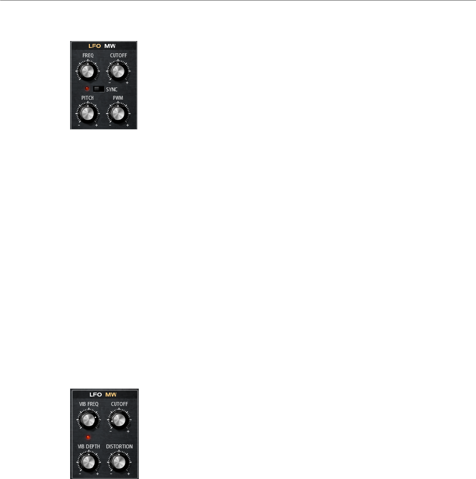
Included Instruments
Voltage
129
LFO Section
Freq
Controls the frequency of the modulation, that is, the speed of the LFO.
Sync
If Sync is activated, the frequency is set in fractions of beats.
Cutoff
Controls the modulation depth of the filter cutoff modulation.
Pitch
Controls the modulation depth of the pitch modulation.
PWM
Controls the modulation depth of the pulse width modulation of the square
oscillators.
Mod Wheel Section
Vib Freq
Controls the frequency of the second LFO that is used for pitch modulation
(vibrato).
Cutoff
Controls the influence of the mod wheel on the filter cutoff.
Vib Depth
Controls the depth of the pitch modulation (vibrato).
Distortion
Controls the influence of the mod wheel on the filter distortion.
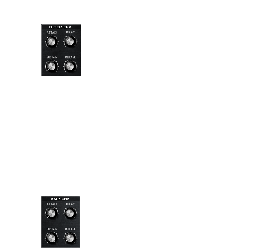
Included Instruments
Voltage
130
Filter Envelope Section
Attack
Controls the attack time of the filter envelope.
Decay
Controls the decay time of the filter envelope.
Sustain
Controls the sustain level of the filter envelope.
Release
Controls the release time of the filter envelope.
Amp Envelope Section
Attack
Controls the attack time of the amplifier envelope.
Decay
Controls the decay time of the amplifier envelope.
Sustain
Controls the sustain level of the amplifier envelope.
Release
Controls the release time of the amplifier envelope.
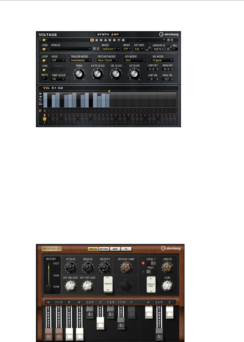
Included Instruments
Model C
131
Arp Page
This page contains the same parameters as the FlexPhraser.
RELATED LINKS
FlexPhraser on page 76
Model C
Model C is a classic tonewheel organ emulation with 9 drawbars and 3 additional drawbars
for the percussion.
Model C comes with an integrated and highly configurable rotary effect, as well as an
amplifier emulation using VST Amp technology. The effect section provides additional effects,
such as phaser, delay, and reverb, and also offers a ring modulator which allows to add non-
harmonic tones. Model C contains four pages: Organ, Rotary, Amp, and FX.
•To open a page, click the corresponding button in the top section of the window.
Organ Page
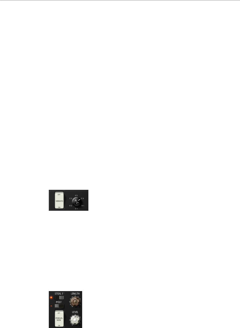
Included Instruments
Model C
132
Drawbars
The main drawbars on the left adjust the levels of the individual tonewheels. The
three drawbars on the right adjust the levels of the tonewheels that are used for
percussion.
Rotary
Allows you to switch from fast to slow speaker rotation. In the middle position,
rotation is stopped. On the Rotary page, you can make detailed settings for the
effect.
Attack
Adjusts the attack time of the organ sound. Typically, the attack is very short, but
you can set longer times to create pad-like sounds.
Release
Adjusts the release time of the organ sound. Typically, the release time is very
short, but you can set longer times to achieve a slow fade out of the sound when
a key is released.
Velocity
Determines the influence of the velocity on the level of the organ sound.
Key On Click/Key Off Click
Electromechanical organs produce short noise signals when a note is triggered
and when it is released. The level of these clicks is set here.
Vibrato
Click the pedal button to activate the integrated vibrato effect. If it is activated,
you can select a type using the control on the right.
Rotary/Amp
The organ signal is sent in parallel to the rotary speaker and to the internal amp.
This control allows you to specify how the signal is distributed between these two
destinations.
• If you turn the control all the way to the left, the signal is sent only to the
rotary speaker. All the way to the right, it is sent only to the amp.
Percussion
Click the pedal button to activate the percussion signal. The following percussion
parameters are available:
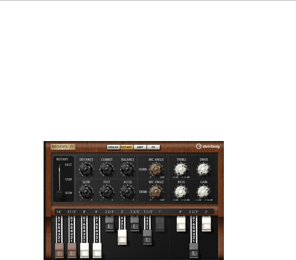
Included Instruments
Model C
133
•Steal 1' – Typically, on an electromechanical organ, the 1' drawbar is not
available when percussion is activated. To prevent this, deactivate the Steal
1' option.
•Poly – Typically, percussion in drawbar organs is monophonic, that is, when
you play a key, the percussion envelope is triggered for this note. As long as
the key is held, no new percussion can be retriggered. If you play a legato
section, for example, percussion is only applied to the very first note or
chord. Percussion can only be retriggered after all notes are released.
To trigger the percussion with every new note, activate Poly.
•Level adjusts the loudness of the percussion signal.
Rotary Page
The settings on this page only have an effect on the sound when signals are sent to the rotary
effect using the Rotary/Amp dial on the Organ page.
The Rotary effect on this page has the same parameters as the included Rotary effect, except
for Input and Color.
RELATED LINKS
Rotary on page 238
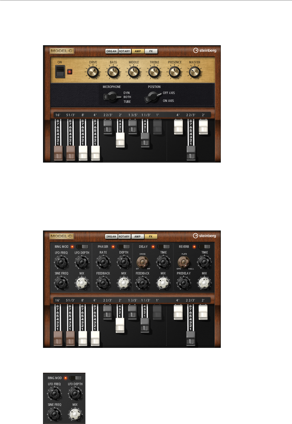
Included Instruments
Model C
134
Amp Page
The settings on this page only have an effect on the sound if signals are sent to the amp
using the Rotary/Amp dial on the Organ page.
The parameters correspond to those of the VST Amp effect, with reduced microphone and
microphone position options.
RELATED LINKS
VST Amp on page 227
FX Page
Ring Modulator
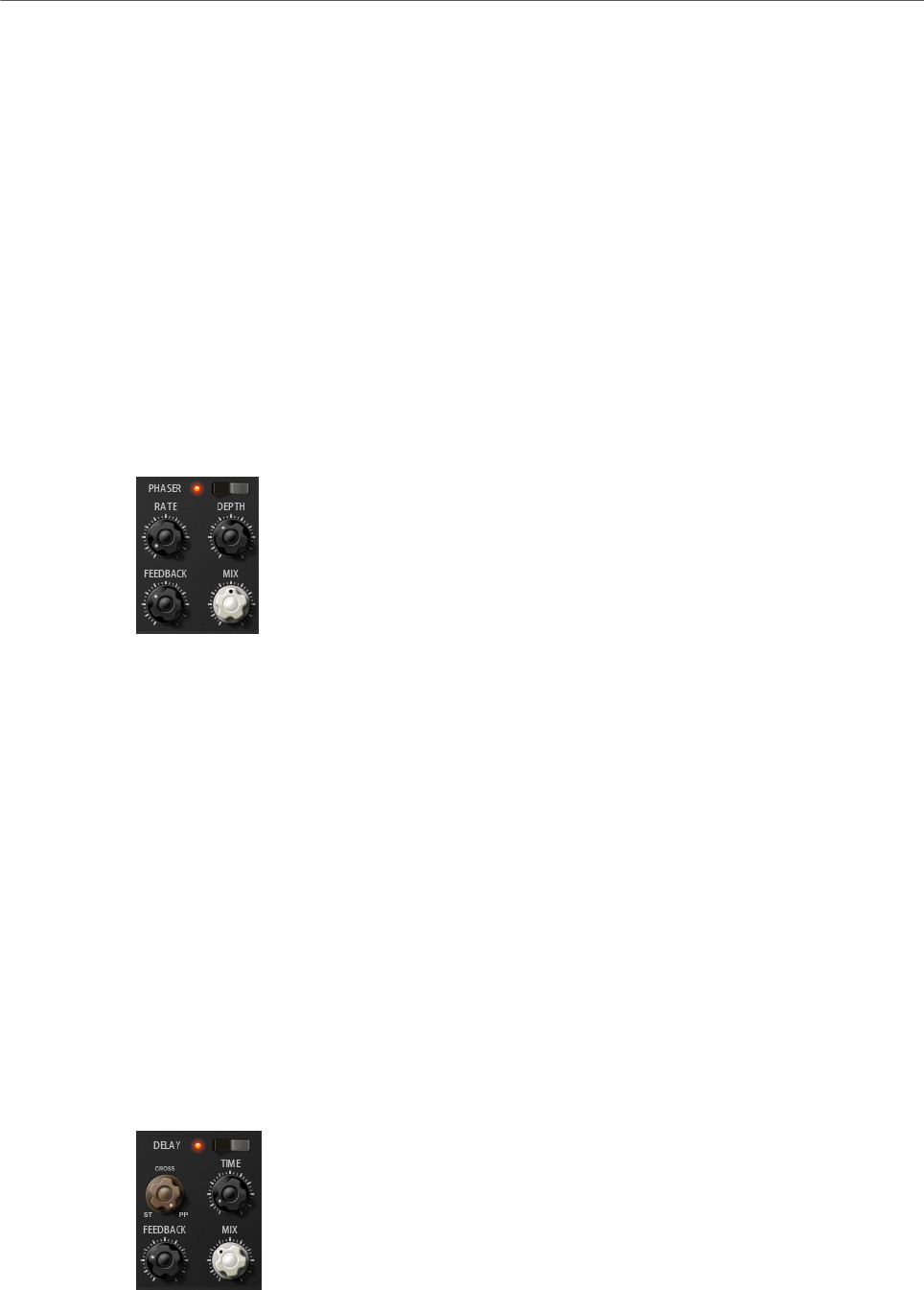
Included Instruments
Model C
135
On/Off
Activates/Deactivates the ring modulator effect.
LFO Freq
Sets the frequency of the LFO for modulating the frequency of the sine oscillator.
LFO Depth
Sets the intensity of the LFO modulation of the sine oscillator frequency.
Sine Freq
Sets the frequency of the sine oscillator.
Mix
Sets the ratio between the dry and the wet signal.
Phaser
On/Off
Activates/Deactivates the Phaser effect.
Rate
Sets the frequency of the phase modulation in Hertz.
Depth
Sets the intensity of the phase modulation.
Feedback
Adds resonances to the effect. Higher settings produce a more pronounced
effect.
Mix
Sets the ratio between the dry and the wet signal.
Delay
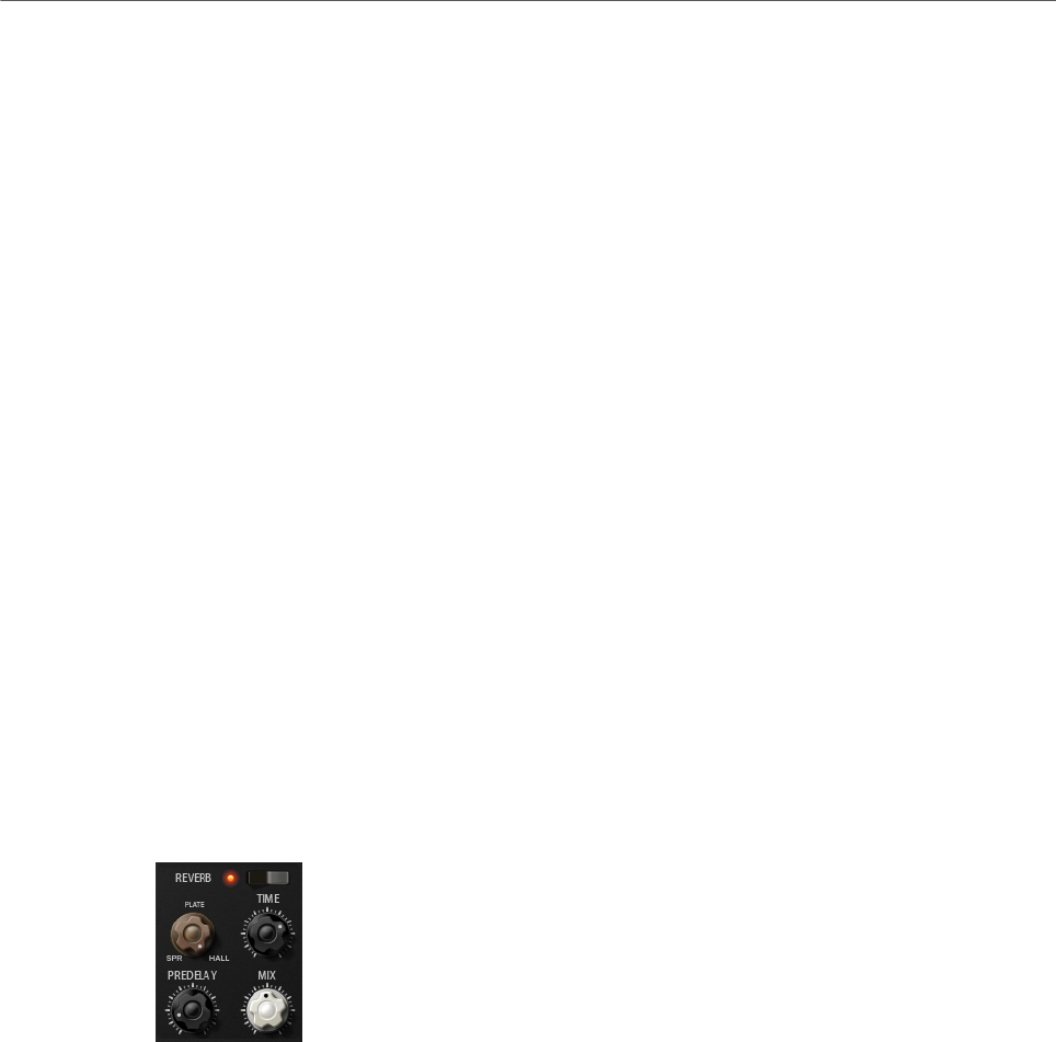
Included Instruments
Model C
136
On/Off
Activates/Deactivates the Delay effect.
Delay Mode
With this dial, you can switch between the three available delay modes:
•St (Stereo) – This mode has two delays in parallel, one for the left and one
for the right audio channel, each with a feedback path of its own.
•Cross – This mode has two delays with cross feedback. Cross feedback
means that the delay of the left channel is fed back into the right delay and
vice versa.
•PP (Ping-Pong) – This mode mixes the left and right input and sends it to
hard-panned left and right delays. This way, the echoes bounce like a ping-
pong ball between left and right in the stereo panorama.
Delay Time
Sets the overall time for the left and right delay in milliseconds.
Feedback
Sets the overall amount of feedback for the left and right delay. Feedback means
the output of the delay is fed back to its input. At a setting of 0 %, you hear only
one echo. At a setting of 100 %, the echoes repeat endlessly.
Mix
Sets the ratio between the dry and the wet signal.
Reverb
On/Off
Activates/Deactivates the Reverb effect.
Reverb Type
Use this dial to switch between the available reverb types: Spring, Plate, and Hall.
Time
Allows you to set the reverb time in seconds.
Predelay
Controls how much time passes before the reverb is applied. This allows you to
simulate larger spaces by increasing the time it takes for first reflections to reach
the listener.
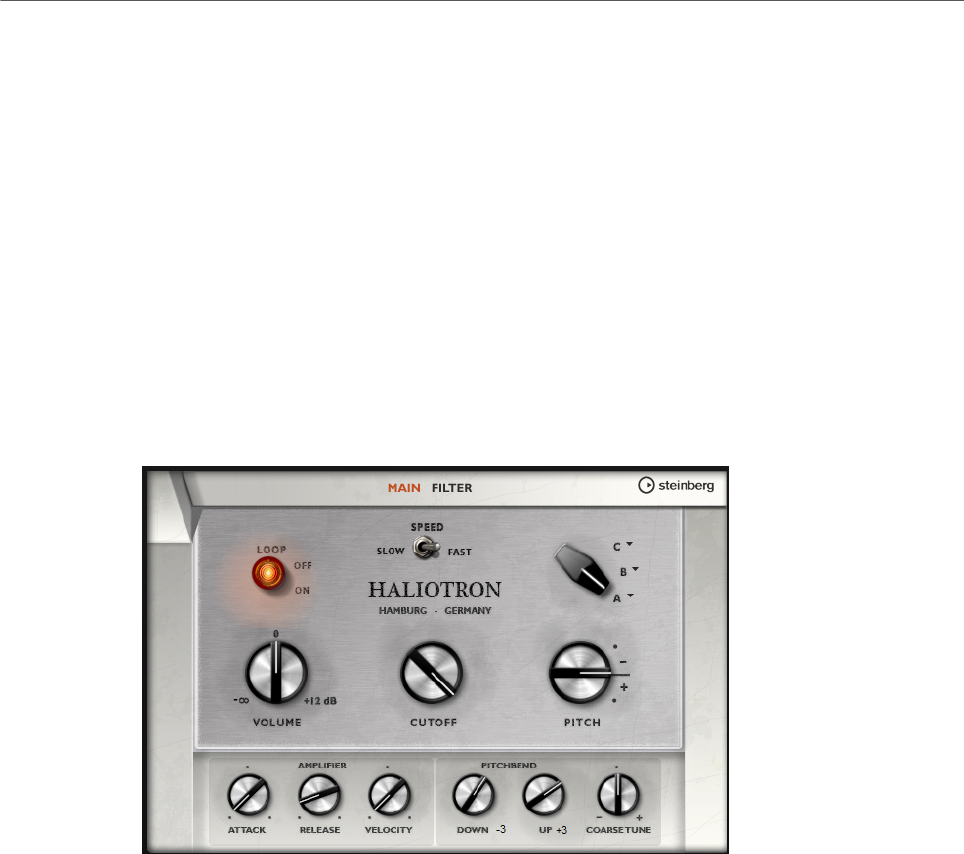
Included Instruments
HALiotron
137
Mix
Sets the ratio between the dry and the wet signal.
HALiotron
HALiotron emulates the sound generation of the pre-digital sampling era.
Before the introduction of digital samplers, original instrument sounds were created by
playing a pre-recorded tape for every key. HALiotron comes with seven different tapes
from these days, which can be blended to create sound mixtures. In addition to its classic
archetype, HALiotron offers a set of the most important synthesis parameters, allowing you
to vary the shape of the sound. Furthermore, you can play sounds dynamically by controlling
filter and amp via velocity.
Main Page
Loop On/Off
Set this to On if you want the notes to be played using looped versions of the
underlying samples and to Off if you want the notes to stop when the tape
reaches its end.
Volume
Adjusts the main volume of the sound.
Speed
Adjusts the speed of the tape playback. If this is set to Slow, the samples are
played back an octave lower.
Cutoff
Adjusts the cutoff frequency of the built-in low-pass filter.
Pitch
Adjusts the tuning of the sound. When you combine several HALiotron presets,
this can be used to make the sound richer.
Included Instruments
HALiotron
138
A, B, C
Click here to select one of the included tapes for each dial position. Use the dial
to blend seamlessly between the tapes.
Attack
Adjusts the attack time of the sound.
Release
Adjusts the release time of the sound.
Velocity
Controls the influence of the velocity on the level of the sound.
Pitchbend Up/Pitchbend Down
Determines the range for the modulation that is applied when you move the
pitchbend wheel.
Coarse Tune
Adjusts the sound in semitone steps. This allows you to play intervals with
multiple layered HALiotron sounds.
Filter Page
Resonance
Adjusts the resonance of the low-pass filter.
Velocity
Sets the influence of the velocity on the level of the sound.
Env Amount
Adjusts the influence of the filter envelope on the cutoff frequency.
KYB
Adjusts the cutoff modulation from the keyboard, that is, cutoff key follow.
Included Instruments
B-Box
139
Attack
Controls the attack time of the filter envelope.
Decay
Controls the decay time of the filter envelope.
Sustain
Controls the sustain level of the filter envelope.
B-Box
B-Box provides you with a veritable drum computer inside HALion Sonic. It comes with 13
instrument lanes that can make use of up to 128 different sounds. You can set up your drum
patterns, create variations, and modify each drum sound using a low-pass filter and several
distortion modes.
B-Box contains three pages: Pattern, Mix, and Aux.
•To open a page, click the corresponding button in the top section of the window.
Pattern Page
The Pattern page is where you create and edit the drum patterns. It gives you access to the
pattern editor as well as to some of the most important sound parameters.
The pattern editor section in the center of the window allows you to create and edit drum
patterns.
• To specify the number of steps for a pattern, drag the small triangle in the lower part
of the pattern display.
The maximum length is 16 steps.
Included Instruments
B-Box
140
• To change the drum sound for a lane, set a new value in the Sound column.
You can choose between up to 128 drum sounds, depending on the selected drum
instrument.
• To preview a drum sound, click the trigger button to the right of the instrument name.
• To add drum steps to the pattern, click on the step fields in the pattern editor.
To add drum steps for all fields on a lane in one go, hold down Shift and click on a field.
• To mute or solo individual lanes, click the corresponding Mute and Solo buttons.
• To set up the velocity for a step, click it and drag up or down or use the mouse wheel.
A step can be set to low, medium, or high velocity.
To change the velocity of all steps in a lane at the same time, hold down Shift and use
the mouse.
NOTE
This function inserts drum steps for every step field on the lane and sets it to the same
velocity. If you want to use only several steps of this lane, you must modify the velocity
separately for each step.
• To remove a step, click it.
To remove all steps, hold down Shift-Ctrl/Cmd and click a step.
Editing the Entire Pattern
• To load a pattern, click in the field below the editor and select it from the pop-up
menu.
• To move all steps of the pattern one step to the left or right, click Shift Pattern Left
or Shift Pattern Right .
This is useful if you have created a pattern that sounds the way you want but does not
start on the first beat, for example.
•To mirror the pattern around its middle step, click Reverse Pattern .
• To copy all steps in the current pattern and insert them behind the current steps, click
Duplicate Pattern .
NOTE
The maximum number of steps in a pattern is 16. If you select Duplicate Pattern and
the resulting pattern would be longer than 16 steps, new steps are inserted until the
maximum length is reached.
• To remove all steps in a pattern, click Clear Pattern .
Setting Up the Drum Sounds
With the controls to the left and right of the pattern editor, you can make settings for the
selected drum instrument.
Coarse
Adjusts the tuning of the instrument in semitone steps.

Included Instruments
B-Box
141
Fine
Fine-tunes the instrument in cent steps.
Pan
Adjusts the panorama position.
Cutoff
Adjusts the cutoff frequency for the instrument.
Resonance
Adjusts the filter resonance for the instrument.
Distortion Type
Sets the distortion type. You can choose between Tube, Hard Clip, Bit Reduction,
and Rate Reduction.
Distortion
Sets the amount of distortion for the instrument.
Level
Sets the level of the instrument.
Playing Back the Pattern
• To play back the pattern, use the play button at the top of the window.
An indicator below the step number shows which step is playing.
Exporting Patterns
• To export a pattern as a MIDI file, drag the MIDI export field into your host application.
Variations
B-Box offers up to 8 variations that can be used to create different rhythm patterns, such as
intros, fills, and endings, for example.
•To switch between variations, click the variation buttons above the pattern editor.
•You can copy and paste variations using the commands on the context menu.
NOTE
The parameters Loop, Sync, Hold, Trigger Mode, Restart Mode, and Input Mode are not part
of the variations.
Variations can be assigned to the trigger pads, allowing you to switch variations on the fly.
RELATED LINKS
Trigger Pads on page 24
Included Instruments
B-Box
142
Mix Page
On the Mix page, you can add effects to the patterns.
Level
Adjusts the level of the instrument.
Pan
Adjusts the panorama position of the instrument.
Delay
Determines how much of the signal is sent to the delay effect.
Reverb
Determines how much of the signal is sent to the reverb effect.
Output
Here, you can select one of the available plug-in outputs.
AUX Page
On the Aux page, you can make global settings for B-Box and the included effects.
The page is divided into two sections. The left section gives you access to the global
performance settings, and the right section allows you to edit the integrated delay and reverb
effects.
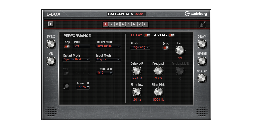
Included Instruments
B-Box
143
Performance Section
Loop
If this option is activated, the pattern plays back in a loop.
Hold
• If this parameter is set to Off, the pattern changes immediately when a key
is released. The pattern stops immediately when all keys are released.
• If the parameter is set to On, the pattern plays to the end even when
the keys are released. If the Loop option is activated, the pattern plays
continuously in a cycle.
• If the parameter is set to Gated, the pattern starts playback with the first
key being played. It plays silently in the background even if the keys are
released, and resumes playback at the current position when you press any
of the keys again. This way, you can gate the playback of the pattern.
Trigger Mode
The trigger mode determines at which moment B-Box changes the pattern when
you select another variation.
• If the parameter is set to Immediately, the pattern changes as soon as you
switch to another variation.
• If the parameter is set to Next Beat, the pattern changes on the first new
beat after switching to another variation.
• If the parameter is set to Next Measure, the pattern changes at the first
new measure after switching to another variation.
Restart Mode
Determines whether the pattern playback is restarted when a note is triggered.
•Off – Playback is not restarted if it is already running.
•First Note – Restarts playback when a note is triggered and no other notes
are playing.
•Each Note – Restarts playback every time a note is triggered.
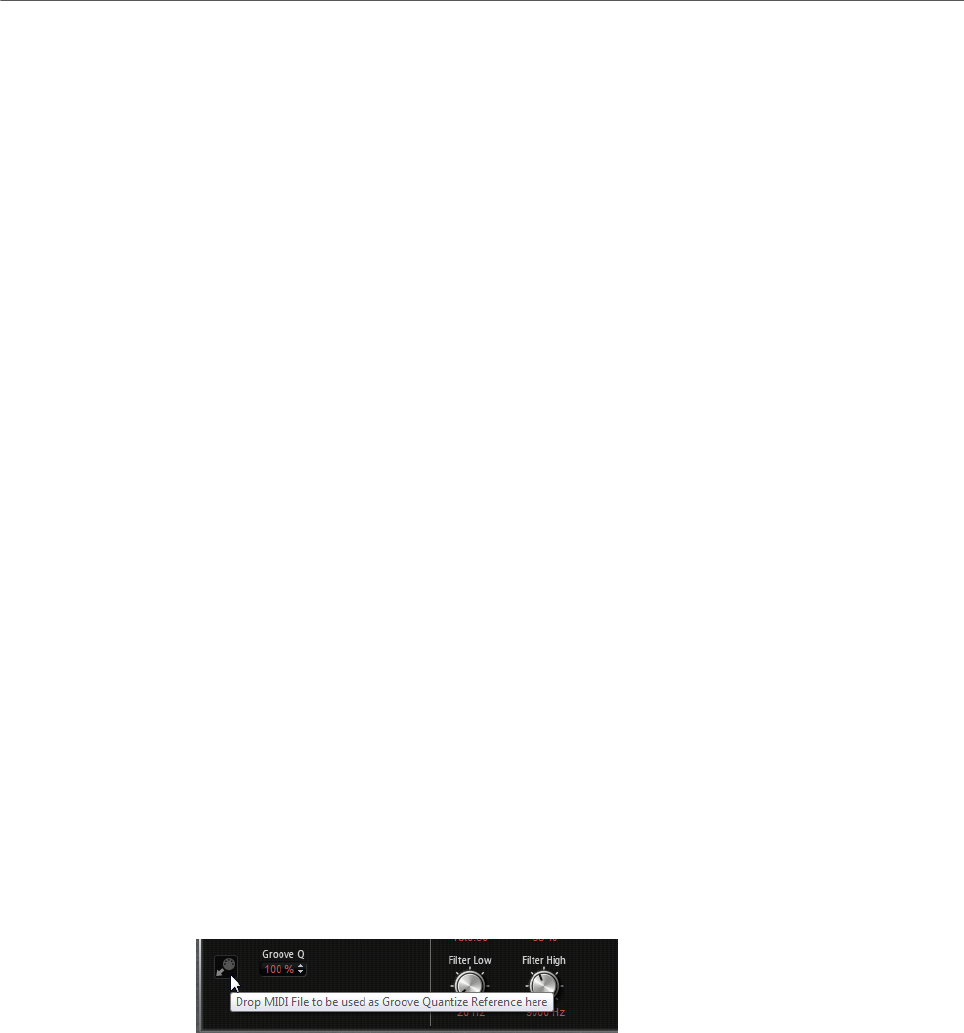
Included Instruments
B-Box
144
•Sync to Host – Aligns playback with the beats and measures of your host
application. Playback is synchronized every time you start the transport.
•Follow Transport – Playback starts and stops automatically together with
the transport controls in your host application.
Input Mode
Keys that trigger the pattern are shown in green on the HALion Sonic keyboard.
Keys that are assigned to an instrument sound are shown as regular black and
white keys.
Depending on the Input Mode, the black and white keys either trigger or mute the
assigned instrument.
•Off triggers the pattern with any key that you play.
•Trigger plays back the sound of the assigned instrument.
•Mute mutes the track for as long as you press the key.
Sync
To synchronize the pattern to the tempo of your host application, activate Sync.
For the modes Sync to Host and Follow Transport, synchronization to the host
application is established automatically. In these modes, the Sync parameter
cannot be edited.
Tempo
If Sync is deactivated, you can use the Tempo parameter to set the internal
playback speed.
Tempo Scale
Defines the speed at which the pattern is running. You can specify a value in
fractions of beats. You can also set dotted and triplet note values. For example, if
the Tempo parameter is set to 1/16 and you set this value to 1/8, the speed is cut
in half.
Groove Quantizing Patterns
To adapt the timing of a pattern to an external MIDI file, you can drop this MIDI
file on the Groove Quantize drop field. You can quantize the playback of the
pattern to the timing of a sliced loop by dragging its MIDI file from the MIDI
export drag field to the Groove Quantize drop field.
The Groove Quantize Depth parameter to the right of the drop field determines
how accurately the pattern follows the timing of the MIDI file.
Swing
Shifts the timing of notes on even-numbered beats. This way, the pattern gets a
swing feeling. Negative values let the notes play earlier, positive values let the
notes play later.
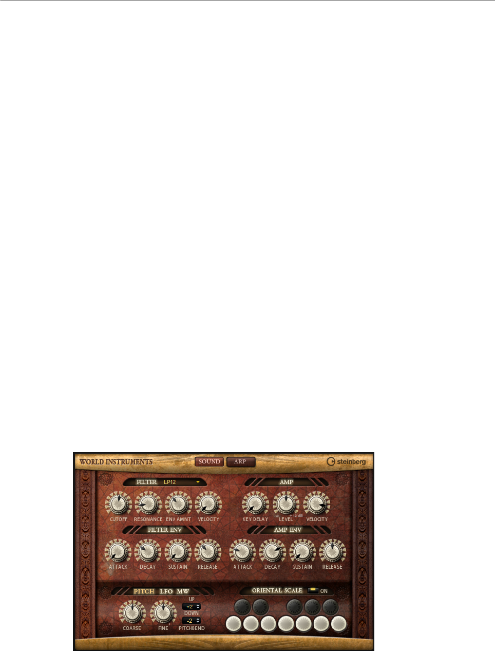
Included Instruments
World Instruments
145
Velocity Scale
Allows you to raise or lower the note-on velocities of the pattern. At a value of 100
%, the notes play with their original velocity.
Delay and Reverb Section
The delay and reverb effect have the same parameters as the Multi Delay and Reverb effects.
Delay
Adjusts the general amount of delay.
Reverb
Adjusts the general amount of reverb.
Master
Adjusts the overall volume of B-Box.
RELATED LINKS
Multi Delay on page 214
Reverb on page 211
World Instruments
World Instruments delivers a great variety of ethnic instruments that can either be played
manually or use the integrated arpeggiator.
On the Sound page, the instruments can be fine-tuned with filter and amp settings. In
addition, you can use the built-in micro-tuning functionality to decrease the pitch of each key
by a quarter note, to realize typical oriental scales.
Sound Page

Included Instruments
World Instruments
146
Filter Section
Filter Shape
• LP24, 18, 12, and 6 are low-pass filters with 24, 18, 12, and 6 dB/oct.
Frequencies above the cutoff are attenuated.
• BP12 and BP24 are band-pass filters with 12 and 24 dB/oct. Frequencies
below and above the cutoff are attenuated.
• HP6+LP18 and HP6+LP12 are combinations of a high-pass filter with 6 dB/
oct and a low-pass filter with 18 and 12 dB/oct, respectively (asymmetric
band-pass filter). Frequencies below and above the cutoff are attenuated.
Attenuation is more pronounced for the frequencies above the cutoff.
• HP12+LP6 and HP18+LP6 are combinations of a high-pass filter with 12
and 18 dB/oct and a low-pass filter with 6 dB/oct (asymmetric band-pass
filter). Frequencies below and above the cutoff are attenuated. Attenuation
is more pronounced for the frequencies below the cutoff.
• HP24, 18, 12, and 6 are high-pass filters with 24, 18, 12, and 6 dB/oct.
Frequencies below the cutoff are attenuated.
• BR12 and BR24 are band-reject filters with 12 and 24 dB/oct. Frequencies
around the cutoff are attenuated.
• BR12+LP6 and BR12+LP12 are combinations of a band-reject filter with 12
dB/oct and a low-pass filter with 6 and 12 dB/oct, respectively. Frequencies
around and above the cutoff are attenuated.
• BP12+BR12 is a band-pass filter with 12 dB/oct plus a band-reject filter
with 12 dB/oct. Frequencies below, above, and around the cutoff are
attenuated.
• HP6+BR12 and HP12+BR12 are combinations of a high-pass filter with 6
and 12 dB/oct and a band-reject filter with 12 dB/oct. Frequencies below
and around the cutoff are attenuated.
• AP is an all-pass filter with 18 dB/oct. Frequencies around the cutoff are
attenuated.
• AP+LP6 is an all-pass filter with 18 dB/oct plus a low-pass filter with 6 dB/
oct. Frequencies around and above the cutoff are attenuated.
• HP6+AP is a high-pass filter with 6 dB/oct plus an all-pass filter with 18
dB/oct. Frequencies around and below the cutoff are attenuated.
Cutoff
Controls the cutoff frequency of the filter.
Resonance
Emphasizes the frequencies around the cutoff. At higher settings, the filter self-
oscillates, which results in a ringing tone.
Envelope Amount
Controls the cutoff modulation from the filter envelope.
Cutoff Velocity
Controls the cutoff modulation from velocity.

Included Instruments
World Instruments
147
Filter Envelope
Attack
Controls the attack time of the filter envelope.
Decay
Controls the decay time of the filter envelope.
Sustain
Controls the sustain level of the filter envelope.
Release
Controls the release time of the filter envelope.
Amp Section
Key Delay
Delays playback of the notes. This parameter can be used when working with
multiple programs or layers. Setting up different key delay values for the different
layers allows you to spread the notes, so that they do not all begin at the same
time.
Level
Controls the overall volume of the sound.
Velocity
Controls the level modulation from velocity. At 0, all notes are played with the
same level.
Amp Envelope
Attack
Controls the attack time of the amplifier envelope.
Decay
Controls the decay time of the amplifier envelope.
Sustain
Controls the sustain level of the amplifier envelope.
Release
Controls the release time of the amplifier envelope.
Pitch Section
Coarse
Adjusts the tuning in semitones.
Fine
Adjusts the tuning in cents.

Included Instruments
World Instruments
148
Pitchbend Up/Pitchbend Down
Determines the range for the modulation that is applied when you move the
pitchbend wheel.
LFO Section
Freq
Controls the frequency of the modulation, that is, the speed of the LFO.
Sync
If Sync is activated, the frequency is set in fractions of beats.
Pitch
Controls the modulation depth of the pitch modulation.
Cutoff
Controls the modulation depth of the filter cutoff modulation.
MW Section
Vib Freq
Controls the frequency of the second LFO that is used for pitch modulation
(vibrato).
Vib Depth
Controls the depth of the pitch modulation (vibrato).
Cutoff
Controls the influence of the mod wheel on the filter cutoff.
Oriental Scale Section
Scale On/Off
Activates/Deactivates the influence of the scale settings on the played notes.
Note Switches
Activate a switch to decrease the tuning of the corresponding note by a quarter
note.
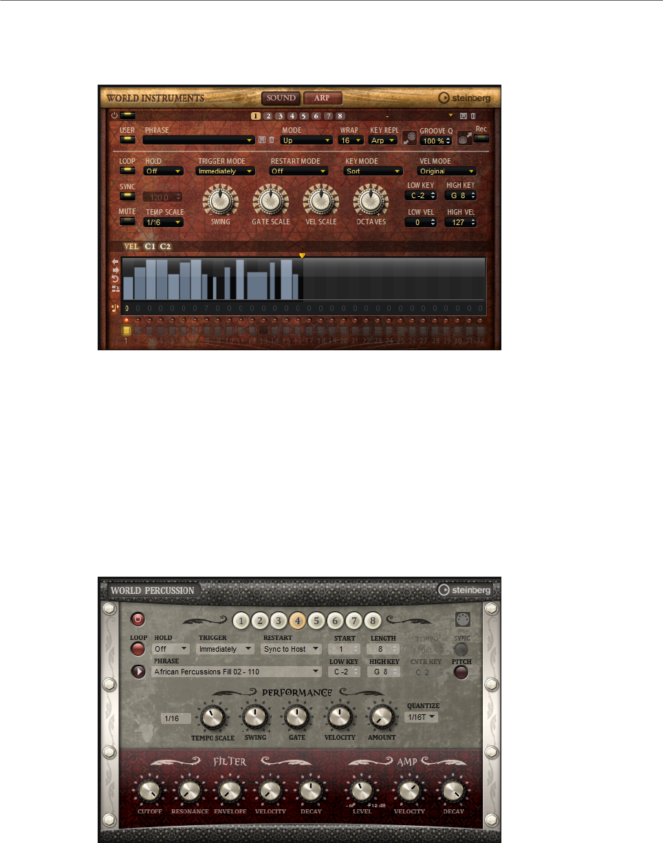
Included Instruments
World Percussion
149
Arp Page
This page contains the same parameters as the FlexPhraser.
RELATED LINKS
FlexPhraser on page 76
World Percussion
World Percussion delivers a great variety of ethnic percussion instruments and associated
MIDI phrases.
The instruments can be globally fine-tuned with filter and amp settings which in turn can
make use of envelope settings. The built-in MIDI player allows you to use the included MIDI
phrases or to import your own MIDI phrases.
MIDI Player Parameters
In the top section of the macro page, the MIDI player parameters are available.

Included Instruments
World Percussion
150
On/Off button
Activates/Deactivates the MIDI player part of World Percussion.
Variation buttons
You can configure up to eight different variations of your sounds and switch
between them with the variation buttons.
NOTE
To avoid switching variations in the middle of a beat or measure, use the trigger
modes Next Beat or Next Measure.
Loading Phrases
To load a phrase, click in the Phrase field and select a phrase from the selector.
Exporting MIDI Phrases
You can export your MIDI phrase as a MIDI file using drag and drop.
Loop
If this button is activated, the phrase plays back in a loop. If this button is
deactivated, the phrase is played once.
Hold
Allows you to prevent the phrase from stopping or changing when the keys are
released.
• If Off is selected, the phrase changes as soon as you release a key. The
phrase stops immediately when you release all keys.
• If On is selected, the phrase plays to the end, even if the keys are released.
If Loop is activated, the phrase repeats continuously.
• If Gated is selected, the phrase starts to play when the first key is played. It
plays silently in the background, even if the keys are released, and resumes
playback at the current position when you press any of the keys again. This
way, you can gate the playback of the phrase.
Trigger Mode
Determines at which moment the player changes the phrase when you select
another variation.
•Immediately – The phrase changes as soon as you switch to another
variation.
•Next Beat – The phrase changes on the first new beat after switching to
another variation.
•Next Measure – The phrase changes on the first new measure after
switching to another variation.
Restart
Depending on the selected Restart mode and your playing, you can restart
playback from the beginning of the loop.
•Off – The loop runs continuously and will not restart upon note changes.

Included Instruments
World Percussion
151
•First Note – The loop restarts when a note is triggered and no other notes
are already held.
•Each Note – The loop restarts each time a note is triggered.
•Sync to Host – Select this to align the loop with the beats and measures of
your host application. The loop aligns to the beats and measures each time
you start the transport.
•Follow Transport – Playback starts and stops automatically together with
the transport controls in your host application.
Start
Shifts the start of the loop in steps of 1/4 notes. The length of the loop is
shortened accordingly.
Length
Allows you to shorten the length of the loop in steps of 1/4 notes.
NOTE
The control range of Start and Length varies with the original length of the loop.
Tempo
• If Sync is deactivated, the Tempo control sets the internal playback speed
of the loop, in BPM. In addition, Tempo Scale gives you further control over
the playback speed.
• If Sync is activated, the Tempo control is inactive.
Sync
To synchronize the loop to the tempo of your host application, activate Sync.
NOTE
In the Restart modes Sync to Host and Follow Transport, synchronization to
the host application is established automatically. In these modes, the Sync
parameter cannot be edited.
Play/Stop
Starts/Stops playback of the phrase.
Low Key
Defines the lowest key on which the phrase is triggered.
High Key
Defines the highest key on which the phrase is triggered.
Center Key
Determines the MIDI note that is used as the central position for the Key Follow
function.

Included Instruments
World Percussion
152
Pitch
Activate this option to set the pitch of the drum sounds according to the center
key.
Performance Section
Tempo Scale
Defines the rate at which notes are triggered, that is, the speed at which the
phrase is running. In addition to the Tempo parameter, this gives you further
control over the playback speed. You can specify a value in fractions of beats. You
can also set dotted and triplet note values.
For example, if you change the Tempo Scale setting from 1/16 to 1/8, the speed
is cut in half. If you set it to 1/32, the speed is doubled. Other values increase or
decrease the speed accordingly.
Swing
Shifts the timing of notes on even-numbered beats. This way, the phrase gets
a swing feeling. Negative values shift the timing backward, and the notes are
played earlier. Positive values shift the timing forward, and the notes are played
later.
Gate Scale
Allows you to shorten or lengthen the notes of the phrase. At a value of 100 %,
the notes play with their original gate length.
Velocity Scale
Raises or lowers the note-on velocities of the phrase. At a value of 100 %, the
notes are played with their original velocity.
Quantize Note Value
This pop-up menu allows you to set up a quantization grid, in fractions of beats.
You can also specify dotted and triplet values. This way, you can force the timing
of the MIDI note events to play back only at the selected note value.
Quantize Amount
Defines how much of the quantization grid is applied. A value of 100 % means
that the MIDI note events play back only at the specified Quantize note value.
Smaller values move the notes only partially towards the next Quantize note
value. At a value of 0 %, no quantization is applied.
Filter Section
Cutoff
Controls the cutoff frequency of the filter.
Resonance
Emphasizes the frequencies around the cutoff. At higher settings, the filter self-
oscillates, which results in a ringing tone.
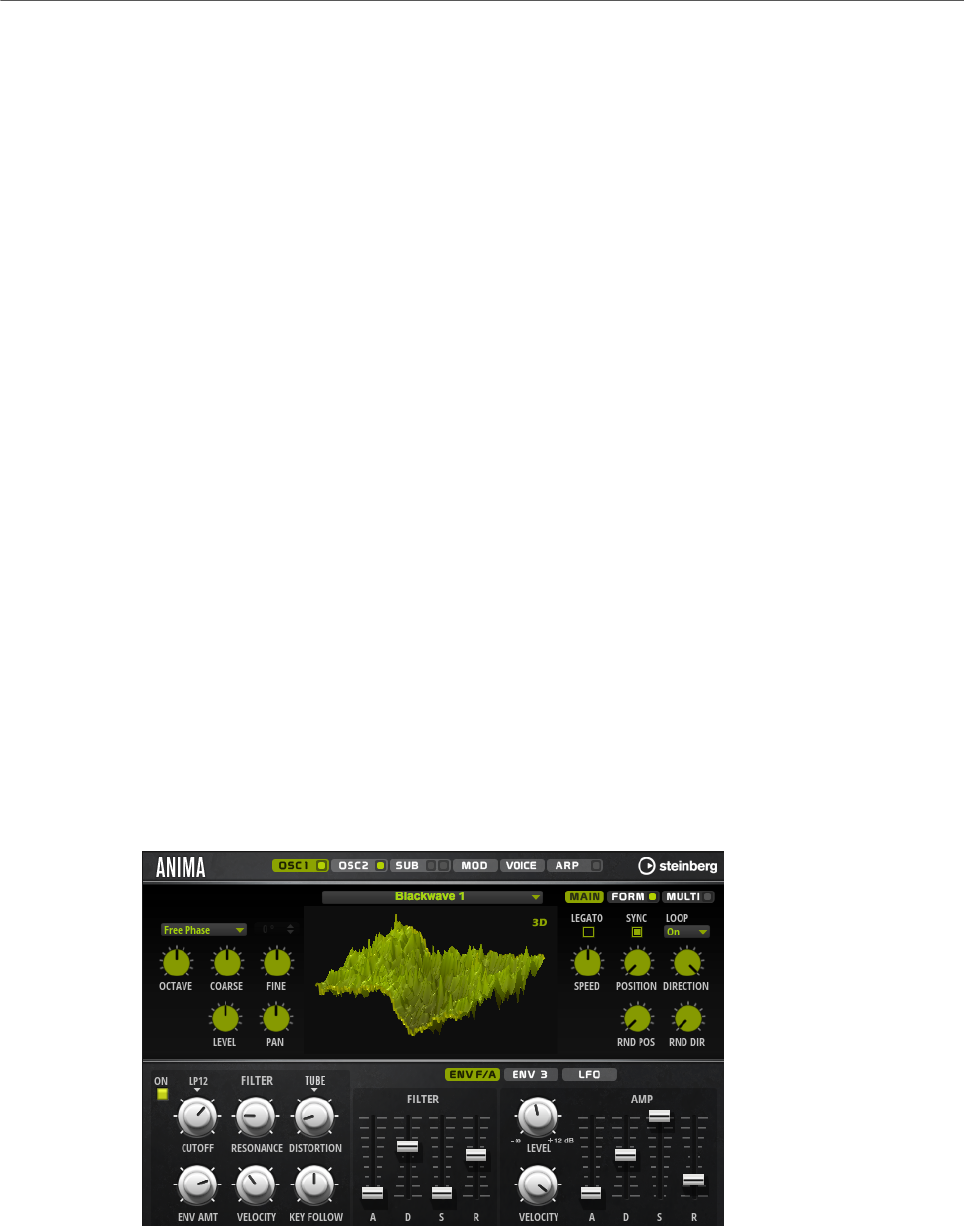
Included Instruments
Anima
153
Envelope Amount
Controls the cutoff modulation from the filter envelope.
Cutoff Velocity
Controls the cutoff modulation from velocity.
Decay
Controls the decay time of the filter envelope.
Amp Section
Level
Controls the overall volume of the sound.
Velocity
Controls the level modulation from velocity. At 0, all notes are played with the
same level.
Decay
Controls the decay time of the amplifier envelope.
Anima
The Anima synth is a wavetable instrument using HALion Sonic’s wavteable synthesis which
crossfades the waves smoothly in real time based on an integrated wavetable envelope. This
envelope makes it very easy to control the playback of the wavetable, because no further
modulation settings are required. All you have to do is set up the Speed parameter. The
modulation matrix allows you to control the playback position of the oscillator using one of
the integrated LFOs, the velocity, or the modulation wheel, for example.
Anima provides two wavetable oscillators that can be used in parallel. Each oscillator
features a multi-oscillator that allows you to create up to eight additional voices for each
oscillator and then separately detune them and distribute them in the stereo panorama.
The sub-oscillator comes with classic oscillator waves like sine, triangle, saw, square and
two different pulses, and also features a noise generator. The noise generator delivers a
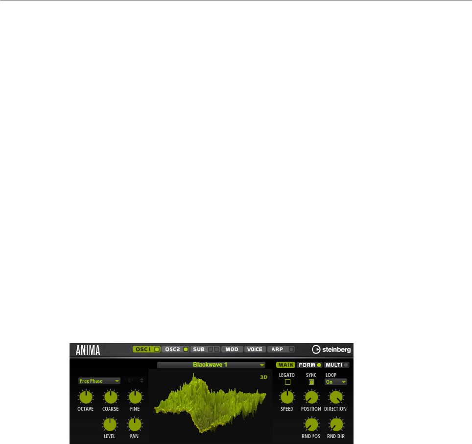
Included Instruments
Anima
154
large number of different noise types. These range from classic noises like white and pink
noise over drum attacks and rhythmical noises to specifically filtered colored noises and
unique circuit noises, recorded from various electronic devices. This powerful collection
of noises can be used to add inharmonic frequencies to create atmospheric sound or add
transients for rich and percussive attacks, for example. The integrated arpeggiator and step
sequencer allows you to play rhythmic patterns and/or add modulations to the synthesis
parameters using the three available controller lanes.
The oscillator is followed by a multi-mode filter that offers a large number of different filter
shapes. The filter can be modulated by modulation sources like the keyboard, velocity, and
LFO, but also by the controller lanes of the step sequencer, for example.
Anima includes two monophonic LFOs that can be synchronized to the host tempo and allow
you to modulate a large number of modulation destinations using the modulation matrix.
In addition, a user-defined envelope can be assigned to destinations like Pitch, Pan, or
Wavetable parameters in the modulation matrix.
Anima contains six pages: Osc1, Osc2, Sub, Mod, Voice, and Arp. To show the settings for a
page, click the corresponding page button.
If a page button itself contains an On/Off button, which is the case for the Arp page button,
for example, you can use this to activate/deactivate the corresponding element without
having to open the page first.
Oscillator Pages
The Osc 1 and Osc 2 pages contain the settings for the two main oscillators.
• To show the settings for oscillator 1 or oscillator 2, click the corresponding button.
• To activate/deactivate an oscillator, click the On/Off button on the right of the
corresponding page button.
Select Wavetable
This pop-up menu allows you to select one of the included wavetables for the
wavetable oscillator.
Show 3D Wavetable Map/2D Wave
Toggles between displaying a single cycle of the current waveform and a
topographic map of the entire wavetable.
Retrigger Mode
• If Free Phase is selected, the behavior of analog synthesizers is emulated.
The oscillator is running freely and continuously.
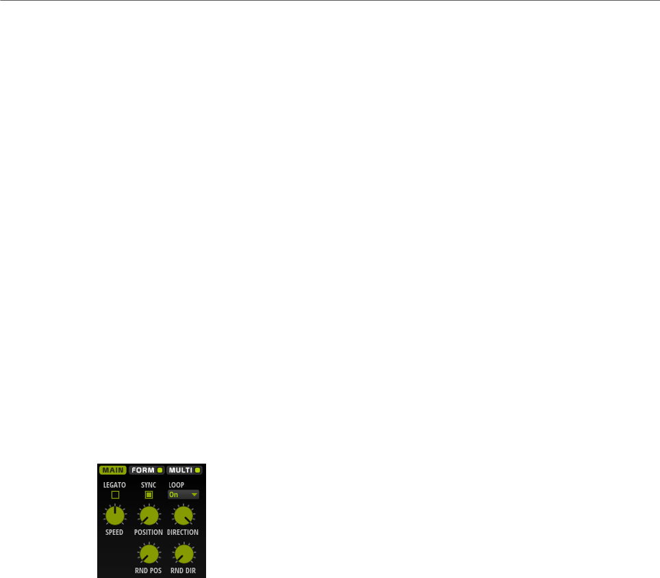
Included Instruments
Anima
155
• If Random Phase is selected, the start phase is randomly set to a different
value each time that you trigger a note. In contrast to Free Phase, there is
no continuity in the phase of the waveform.
• If Fixed Phase is selected, the oscillator runs with a fixed start phase that
can be specified between 0 and 360 degrees.
Octave
Adjusts the pitch in octave steps.
Coarse
Adjusts the pitch in semitone steps.
Fine
Adjusts the pitch in cent steps. This allows you to fine-tune the oscillator sound.
Level
Adjusts the output level of the oscillator.
Pan
Adjusts the position of the oscillator in the stereo panorama. At a setting of -100
%, the sound is panned hard left, and at +100 %, it is panned hard right.
Main Tab
Legato
If Legato is deactivated, each note starts playback from the position cursor.
If Legato is activated, the first note starts playback from the position cursor, and
any following notes start from the current playback position for as long as the
first note is held.
Sync to Host
Allows you to sync the wavetable to the beats and measures of your host
application.
Loop Mode
•Off: If Playback Direction is set to a positive value, the wavetable plays from
the position cursor to the end.
If Playback Direction is set to a negative value, the wavetable plays from
the position cursor to the start.
•On: Depending on the Playback Direction setting, the wavetable plays
forward or backward in a loop.

Included Instruments
Anima
156
•Alt: The wavetable plays in an alternate loop, that is, the loop is alternately
played forward and backward. The first direction depends on the Playback
Direction setting.
Speed
Determines the rate at which the envelope plays through the wavetables. At +100
%, the envelope plays back at its original speed. A value of +50 % corresponds to
half the original speed, and +200 % to twice the original speed, for example.
This parameter is unipolar.
Position
Determines where the envelope starts.
Playback Direction
Allows you to set the playback speed in smaller increments. Furthermore, this
parameter determines the playback direction.
• If you enter negative values, you reverse playback, that is, the playback
position moves backward through the wavetable.
Random Position
Adds a random value to the current position when you play a note.
For example, if you want the position to vary between 25.0 % and 75.0 %, set
Position to 25.0 % and Random Position to 50.0 %.
Random Direction
Adds a negative or positive random value to the current direction when you play a
note.
For example, if you want the direction to vary between -100 % and +100 %, set
Direction to 0.0 % and Random Direction to 100.0 %. If you want the direction to
vary within the full positive range, set Direction to 50 % and Random Direction to
50 %, for example.
Form Tab
Formants are harmonics within the spectrum of a note which are pronounced and help
to define the character of an instrument. The positions of the formants in the spectrum
mainly depend on the construction of an instrument, such as the body of a guitar, the form
of the vocal tract in a human body, the filter settings for electronic instruments, etc. These
conditions lead to specific frequency ranges that are emphasized regardless of the pitch
of the note. Playing back samples or wavetables with a different pitch than the original is
usually done by increasing or decreasing the playback speed. This leads to the well known
monster or Mickey Mouse effect, because all harmonics are also affected, that is, the
characteristic formants are shifted. To avoid this, you can activate the Formant option.
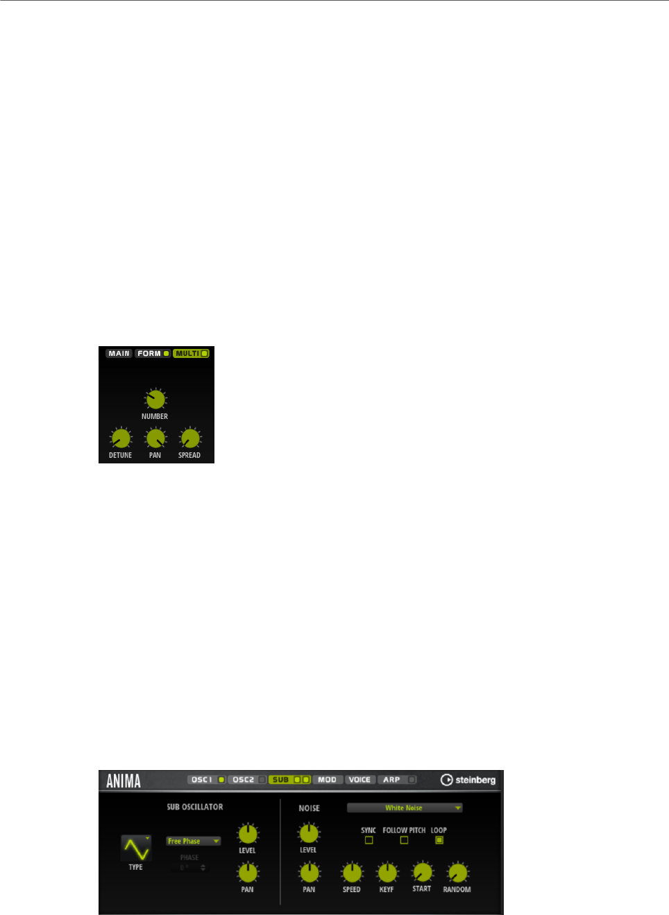
Included Instruments
Anima
157
On/Off
Activates/Deactivates the formant settings.
Formant
Allows you to shift the formants of the entire wavetable by a fixed value.
Key Follow
Allows you to shift the formants depending on the played note.
• A value of 100 % means that the formant frequency moves with the played
note.
• A value of 0 % means that the formants kept the same for all notes.
You can invert the behavior of the formant shift by setting Key Follow to negative
values.
Multi Tab
The multi-oscillator function allows you to trigger multiple voices simultaneously with each
note that you play. If you activate Multi, the following parameters become available:
•Number determines the number of oscillators that play back simultaneously. You
can also set fractions of numbers. For example, with a setting of 2.5, you hear two
oscillators at full level and a third one at half level.
•Detune detunes the oscillators.
•Pan narrows or widens the stereo panorama. With a setting of 0 %, you create a mono
signal and with 100 %, you create a stereo signal.
•Spread distributes the oscillators so that each oscillator plays from a different position
in the wavetable.
Sub Page
The Sub page contains the settings for the sub oscillator and the noise oscillator.

Included Instruments
Anima
158
Sub Oscillator Section
Type
The wave shape of the sub oscillator. You can choose between Sine, Triangle,
Saw, Square, Pulse Wide, and Pulse Narrow.
Retrigger Mode
• If Free Phase is selected, the behavior of analog synthesizers is emulated.
The oscillator is running freely and continuously.
• If Random Phase is selected, the start phase is randomly set to a different
value each time that you trigger a note. In contrast to Free Phase, there is
no continuity in the phase of the waveform.
• If Fixed Phase is selected, the oscillator runs with a fixed start phase that
can be specified between 0 and 360 degrees.
Level
Adjusts the output level of the sub oscillator.
Pan
Adjusts the position of the oscillator in the stereo panorama. At a setting of -100
%, the sound is panned hard left, and at +100 %, it is panned hard right.
Noise Oscillator Section
The noise oscillator offers you a large amount of different noise types that can be used to
add inharmonic frequencies to the overall spectrum, either for the entire sound, with looped
noises or with one-shot noise samples. This allows you to add characteristic transients to
percussive instruments based on samples, for example.
Noise Type
This pop-up menu offers you a choice of classic noises, attack transients,
soundscapes, and ambience noise samples.
Level
Adjusts the output level of the Noise section.
Sync
Activate Sync to synchronize the speed of the noise oscillator to the host tempo.
This is particularly useful for rhythmic noises that are based on a tempo of 120
BPM.
Pan
Determines the position of the noise in the stereo panorama. At a setting of -100
%, the sound is panned hard left, and at +100 %, it is panned hard right.
Follow Pitch
If Follow Pitch is activated, zone pitch settings like Octave, Coarse, and Fine, as
well as modulations like Glide, Pitchbend, or other pitch modulations, affect the
duration length. A higher sample pitch leads to a shorter duration.
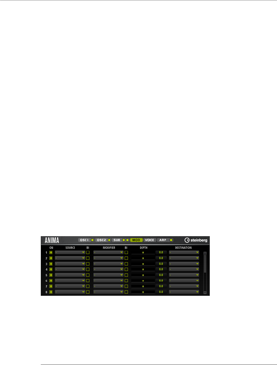
Included Instruments
Anima
159
If Follow Pitch is deactivated, the duration is independent of the zone pitch and
determined by the Duration settings.
Loop
Activate this button to play the noise sample in a loop.
If this button is not activated, the sample is played once.
Speed
Adjusts the playback speed of the noise sample. A setting of 800.0 % equals an
increase of three octaves in pitch.
Speed Key Follow
Allows you to adjust the speed modulation by MIDI note number. At a setting of
+100 %, the speed doubles per octave.
Start
Adjusts the start of the noise sample. With a value of 50 %, playback starts in the
middle of the sample.
Random Start
Selects a random playback start within a specific range around the current
position.
At a setting of 100 %, the playback position jumps to a random position between
the specified Start value and the end of the noise sample.
Mod Page
The Mod page contains the modulation matrix.
The modulation matrix offers you up to 16 freely assignable modulations, each with a source,
a modifier, and a destination with adjustable depth. The polarity of each source and each
modifier can be switched between unipolar and bipolar.
Creating Modulations
You create modulations by selecting a source, a modifier, and a destination from the pop-up
menus in the modulation matrix.
PROCEDURE
1. Click the modulation Source field and select the modulation source.
2. Optional: Click in the modulation Modifier field and select the parameter that you want
to use to modify the modulation.

Included Instruments
Anima
160
This modifier is used to scale the output of the modulation source.
3. Optional: Specify whether you want the Source and Modifier parameters to be unipolar
or bipolar.
4. Set the modulation intensity with the Depth parameter.
5. Click in the modulation Destination field and select the parameter that you want to
modulate.
Modulation Matrix Parameters
Modulation Sources and Modulation Modifiers
The following options are available as modulation sources and as modulation modifiers.
LFO A/B
The LFOs A and B produce cyclic modulation signals.
Amp Envelope
The amplifier envelope. The shape of the envelope determines the modulation
signal.
Filter Envelope
The filter envelope. The shape of the envelope determines the modulation signal.
Env 3
A freely assignable envelope. It is suited for pan or pitch modulation, for example.
Key Follow
This produces an exponential modulation signal derived from the MIDI note
number. Exponential means this source works with destinations such as Pitch or
Cutoff.
Note-on Velocity
Note-on velocity can be used as modulation signal.
Note-on Vel Squared
The squared version of Note-on Velocity. The harder you press the key, the higher
the modulation values.
Pitchbend
The position of the pitchbend wheel can be used as modulation signal.
Modulation Wheel
The position of the modulation wheel can be used as modulation signal.
Aftertouch
Aftertouch can be used as modulation signal. Some MIDI keyboards cannot send
aftertouch messages. However, most sequencer software is able to produce such
messages.

Included Instruments
Anima
161
Arp Controller 1–3
The 3 controllers available on this submenu correspond to the three controller
lanes on the Arp page.
Bus 1–8
Modulations that are sent to one of the eight busses can be reused as sources.
This way, you can combine several modulations to produce more complex
signals.
Quick Control 1–8
The quick controls can be used as modulation signal.
Unipolar vs. Bipolar Sources
The polarity of a modulation source specifies the value range that it produces. Unipolar
sources modulate between 0 and +1. Bipolar sources modulate between -1 and +1.
• To change the polarity of a modulation source or modifier from unipolar to bipolar,
activate its Bipolar button.
Modulation Destinations
Pitch
Modulates the pitch. For example, assign one of the LFOs to create a vibrato
effect. If Pitch is selected, the modulation depth is set in semitones.
Cutoff
Modulates the filter cutoff.
Resonance
Modulates the filter resonance. Resonance changes the character of the filter.
For example, to accent the filter the harder you hit a key, assign Velocity to
Resonance.
Distortion
Modulates the filter distortion.
Level
This modulation adds to the level setting. It can be used to create level offsets
using the mod wheel, for example.
Volume
Modulates the gain. The volume modulation multiplies with the level.
Pan
Modulates the position of the sound in the panorama.
WT 1/2 Pitch
Modulates the Pitch parameter of the corresponding wavetable oscillator.

Included Instruments
Anima
162
WT 1/2 Level
Modulates the Level parameter of the corresponding wavetable oscillator.
WT 1/2 Pan
Modulates the Pan parameter of the corresponding wavetable oscillator.
WT 1/2 Multi Detune
Modulates the multi-oscillator Detune parameter of the corresponding wavetable
oscillator.
WT 1/2 Multi Pan
Modulates the multi-oscillator Pan parameter of the corresponding wavetable
oscillator.
WT 1/2 Multi Spread
Modulates the multi-oscillator Spread parameter of the corresponding wavetable
oscillator.
WT 1/2 Multi Voices
Modulates the multi-oscillator Voices parameter of the corresponding oscillator.
WT 1/2 Position
Modulates the Position parameter of the corresponding wavetable oscillator.
WT 1/2 Direction
Modulates the Direction parameter of the corresponding wavetable oscillator.
WT 1/2 Speed
Modulates the Speed parameter of the corresponding wavetable oscillator.
WT Sub Pitch
Modulates the Pitch parameter of the wavetable sub-oscillator.
WT Sub Level
Modulates the Level parameter of the wavetable sub-oscillator.
WT Sub Pan
Modulates the Pan parameter of the wavetable sub-oscillator.
WT Noise Speed
Modulates the Speed parameter of the wavetable noise oscillator.
WT Noise Level
Modulates the Level parameter of the wavetable noise oscillator.
WT Noise Pan
Modulates the Pan parameter of the wavetable noise oscillator.

Included Instruments
Anima
163
Amp Env Attack
Modulates the attack time of the amplitude envelope. This modulation
destination cannot be modulated continuously. The time is updated only when the
segment starts.
Amp Env Decay
Modulates the decay time of the amplitude envelope. This modulation destination
cannot be modulated continuously. The time is updated only when the segment
starts.
Amp Env Sustain
Modulates the sustain level of the amplitude envelope. This modulation
destination cannot be modulated continuously. The level is updated only when the
segment starts.
Amp Env Release
Modulates the release time of the amplitude envelope. This modulation
destination cannot be modulated continuously. The time is updated only when the
segment starts.
Filter Env Attack
Modulates the attack time of the filter envelope. This modulation destination
cannot be modulated continuously. The time is updated only when the segment
starts.
Filter Env Decay
Modulates the decay time of the filter envelope. This modulation destination
cannot be modulated continuously. The time is updated only when the segment
starts.
Filter Env Sustain
Modulates the sustain level of the filter envelope. This modulation destination
cannot be modulated continuously. The level is updated only when the segment
starts.
Filter Env Release
Modulates the release time of the filter envelope. This modulation destination
cannot be modulated continuously. The time is updated only when the segment
starts.
Env 3 Start Level
Modulates the start level of the user-definable envelope 3, that is, the level
of the first envelope node. This modulation destination cannot be modulated
continuously. The level is updated only when the segment starts.
Env 3 Attack
Modulates the attack time of the user-definable envelope 3. This modulation
destination cannot be modulated continuously. The time is updated only when the
segment starts.
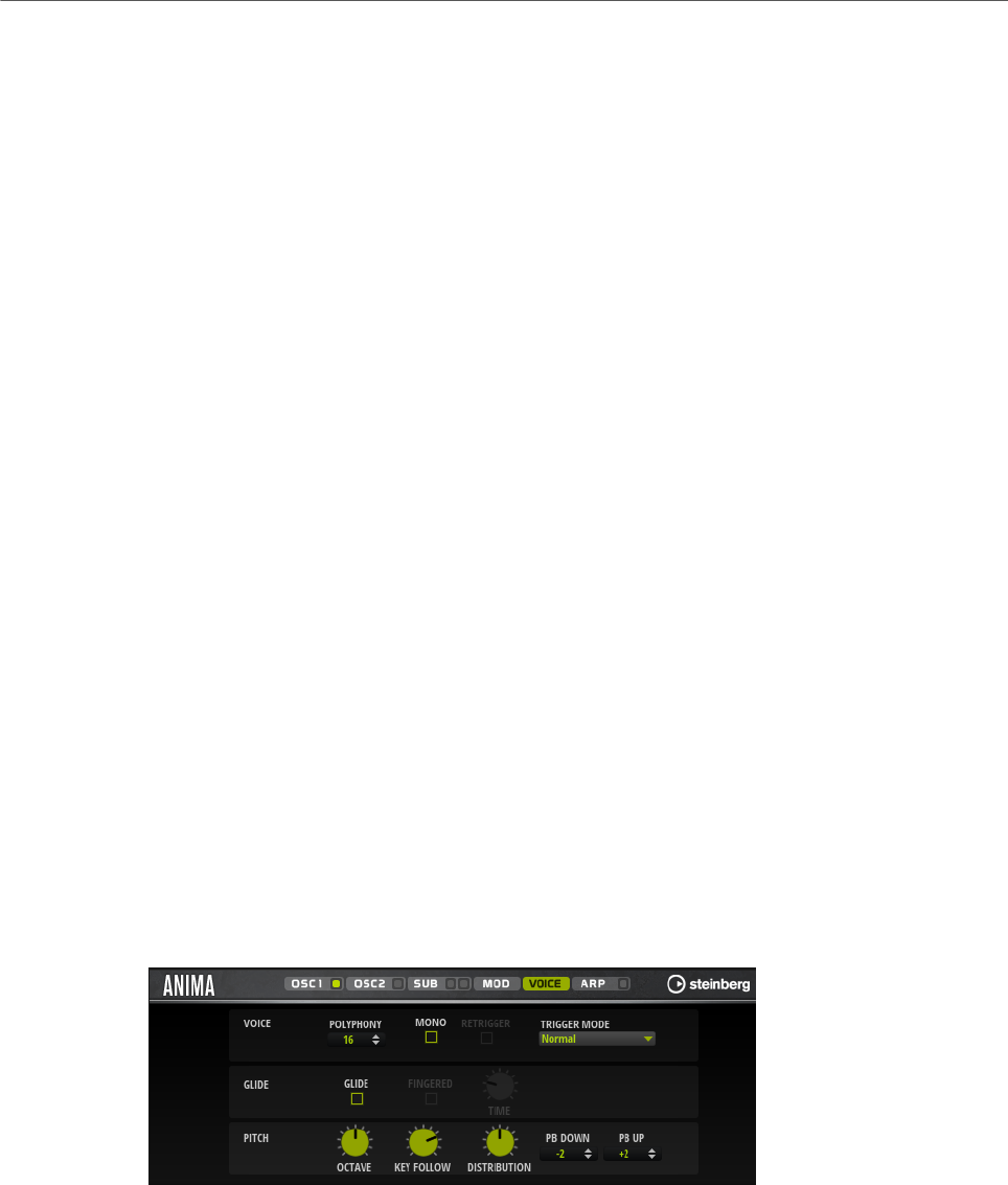
Included Instruments
Anima
164
Env 3 Attack Level
Modulates the attack level of the user-definable envelope 3, that is, the level of
the second envelope node. This modulation destination cannot be modulated
continuously. The level is updated only when the segment starts.
Env 3 Decay
Modulates the decay time of the user-definable envelope 3. This modulation
destination cannot be modulated continuously. The time is updated only when the
segment starts.
Env 3 Sustain
Modulates the sustain level of the user-definable envelope 3. This modulation
destination cannot be modulated continuously. The level is updated only when the
segment starts.
Env 3 Release
Modulates the release time of the user-definable envelope 3. This modulation
destination cannot be modulated continuously. The time is updated only when the
segment starts.
Env 3 Release Level
Modulates the release level of the user-definable envelope 3, that is, the
last user envelope node. This modulation destination cannot be modulated
continuously. The level is updated only when the segment starts.
Bus 1-8
You can send any modulation to one of the 8 busses, for example, to produce
more complex modulation signals. Select the bus that you want to send the
signals to as a destination. To use the modulation that was sent to a bus, assign
the corresponding bus as a modulation source.
Voice Page
Polyphony
If Mono mode is deactivated, you can use this parameter to specify how many
notes can be played simultaneously.
Mono
Activates monophonic playback.

Included Instruments
Anima
165
Retrigger
This option is only available in Mono mode. If Retrigger is activated, a note that
was stolen by another note is retriggered if you still hold the stolen note when
you release the new one.
This way, you can play trills by holding one note and quickly and repeatedly
pressing and releasing another note, for example.
Trigger Mode
Defines the trigger behavior for new notes.
•Normal triggers a new note when the previous note gets stolen. The
sample and the envelope of the new note are triggered from the start.
To minimize discontinuities, use the Fade Out parameter of the zone.
•Resume does not always trigger a new note.
If the new note stays within the same zone, the envelope is retriggered, but
resumes at the level of the stolen note. The pitch of the zone is set to the
new note.
If the new note plays in a different zone, the sample and the envelope of the
new note are triggered from the start.
•Legato does not always trigger a new note.
If the new note stays within the same zone, the envelope keeps running.
The pitch of the zone is set to the new note.
If the new note plays in a different zone, the sample and the envelope of the
new note are triggered from the start.
•Resume Keeps Zone does not trigger a new note upon note stealing. The
envelope resumes at the level of the stolen note and the pitch of the zone is
set to the new note, even if the new note plays in a different zone.
•Legato Keeps Zone does not trigger a new note upon note stealing. The
envelope keeps running and the pitch of the zone is set to the new note,
even if the new note plays in a different zone.
Glide
Allows you to bend the pitch between notes that follow each other. You achieve
the best results in Mono mode.
Fingered
Activate this parameter to glide the pitch only between notes that are played
legato.
Glide Time
Sets the glide time, that is, the time it takes to bend the pitch from one note to
the next.
Octave
Adjusts the pitch in octave steps.
Pitch Key Follow
Allows you to adjust the pitch modulation by MIDI note number. Set this
parameter to positive values in order to raise the pitch the higher you play. Use
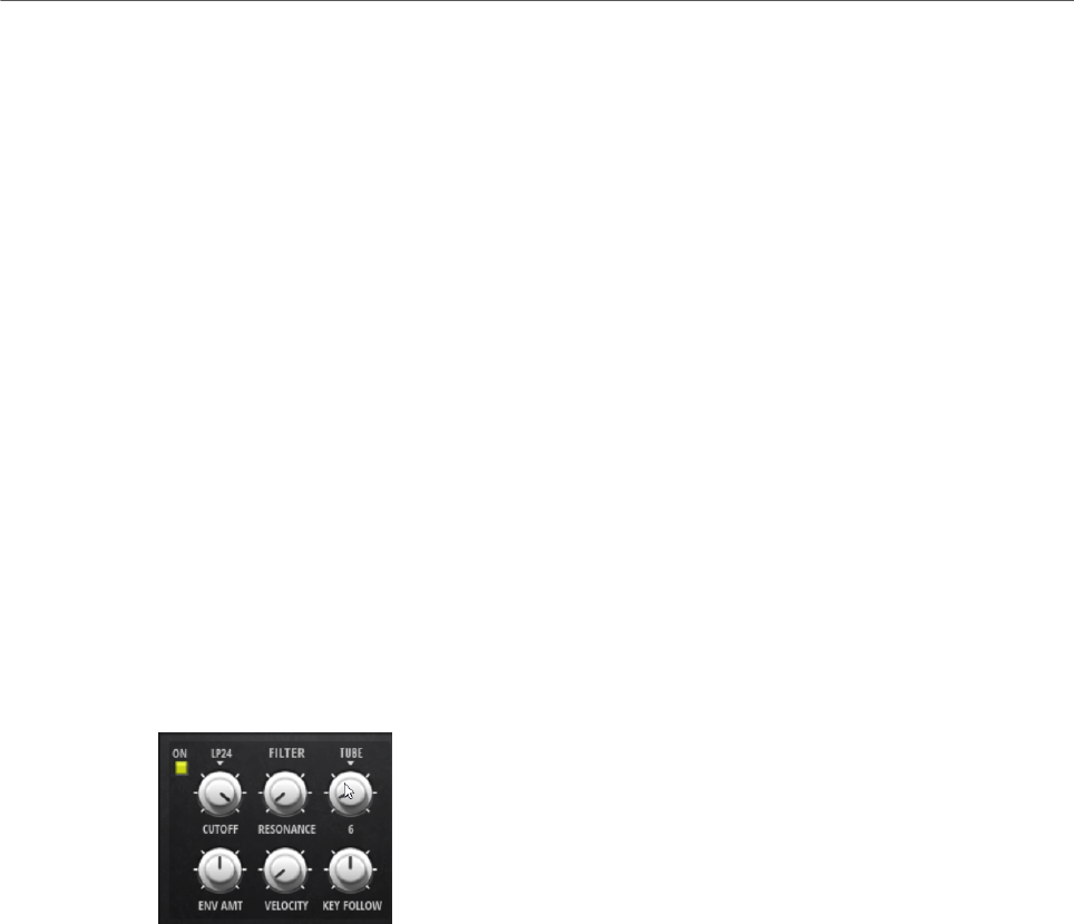
Included Instruments
Anima
166
negative values to lower the pitch the higher you play. At a setting of +100 %, the
pitch follows the played note exactly.
Distribution
Allows you to specify how unison voices are spread in pitch. Changing the unison
voice distribution will create different modulations between the unison voices.
• If this is set to 0, the distribution is linear, that is, all voices have an equal
distance in their pitch offset.
• Raising the value stretches the distribution using an exponential curve, so
that the first unison voices have a smaller pitch offset than the second and
third.
• Decreasing the value stretches the distribution using a negative
exponential curve,so that the first unison voices have a larger pitch offset
than the second and third voices.
Pitchbend Up/Pitchbend Down
Determines the range for the modulation that is applied when you move the
pitchbend wheel.
Filter Section
In the filter section in the lower left, you can activate and set up the filter.
Filter On/Off
Activates/Deactivates the filter.
Filter Shape
• LP24, 18, 12, and 6 are low-pass filters with 24, 18, 12, and 6 dB/oct.
Frequencies above the cutoff are attenuated.
• BP12 and BP24 are band-pass filters with 12 and 24 dB/oct. Frequencies
below and above the cutoff are attenuated.
• HP6+LP18 and HP6+LP12 are combinations of a high-pass filter with 6 dB/
oct and a low-pass filter with 18 and 12 dB/oct, respectively (asymmetric
band-pass filter). Frequencies below and above the cutoff are attenuated.
Attenuation is more pronounced for the frequencies above the cutoff.
• HP12+LP6 and HP18+LP6 are combinations of a high-pass filter with 12
and 18 dB/oct and a low-pass filter with 6 dB/oct (asymmetric band-pass
filter). Frequencies below and above the cutoff are attenuated. Attenuation
is more pronounced for the frequencies below the cutoff.
• HP24, 18, 12, and 6 are high-pass filters with 24, 18, 12, and 6 dB/oct.
Frequencies below the cutoff are attenuated.

Included Instruments
Anima
167
• BR12 and BR24 are band-reject filters with 12 and 24 dB/oct. Frequencies
around the cutoff are attenuated.
• BR12+LP6 and BR12+LP12 are combinations of a band-reject filter with 12
dB/oct and a low-pass filter with 6 and 12 dB/oct, respectively. Frequencies
around and above the cutoff are attenuated.
• BP12+BR12 is a band-pass filter with 12 dB/oct plus a band-reject filter
with 12 dB/oct. Frequencies below, above, and around the cutoff are
attenuated.
• HP6+BR12 and HP12+BR12 are combinations of a high-pass filter with 6
and 12 dB/oct and a band-reject filter with 12 dB/oct. Frequencies below
and around the cutoff are attenuated.
• AP is an all-pass filter with 18 dB/oct. Frequencies around the cutoff are
attenuated.
• AP+LP6 is an all-pass filter with 18 dB/oct plus a low-pass filter with 6 dB/
oct. Frequencies around and above the cutoff are attenuated.
• HP6+AP is a high-pass filter with 6 dB/oct plus an all-pass filter with 18
dB/oct. Frequencies around and below the cutoff are attenuated.
Cutoff
Controls the cutoff frequency of the filter.
Resonance
Emphasizes the frequencies around the cutoff. At higher settings, the filter self-
oscillates, which results in a ringing tone.
Distortion
Adds distortion to the signal. The following distortion types are available:
•Tube adds warm, tube-like distortion.
•Hard Clip adds bright, transistor-like distortion.
•Bit Reduction adds digital distortion by means of quantization noise.
•Rate Reduction adds digital distortion by means of aliasing.
•Rate Reduction Key Follow adds digital distortion by means of aliasing, but
with Key Follow. The rate reduction follows the keyboard, so the higher you
play, the higher the sample rate.
Envelope Amount
Controls the cutoff modulation from the filter envelope.
Cutoff Velocity
Controls the cutoff modulation from velocity.
Cutoff Key Follow
Adjusts the cutoff modulation using the note number. Increase this parameter
to raise the cutoff with higher notes. At 100 %, the cutoff follows the played pitch
exactly.
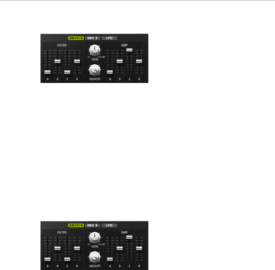
Included Instruments
Anima
168
Filter Envelope
On the left on the Env F/A tab, you can set up the filter envelope.
Attack
Controls the attack time of the filter envelope.
Decay
Controls the decay time of the filter envelope.
Sustain
Controls the sustain level of the filter envelope.
Release
Controls the release time of the filter envelope.
Amplifier and Amplifier Envelope
On the right of the Env F/A tab, you can make settings for the amplifier and the amplifier
envelope.
Amplifier Parameters
Level
Controls the overall volume of the sound.
Velocity
Controls the level modulation from velocity. At 0, all notes are played with the
same level.
Amplifier Envelope Parameters
Attack
Controls the attack time of the amplifier envelope.
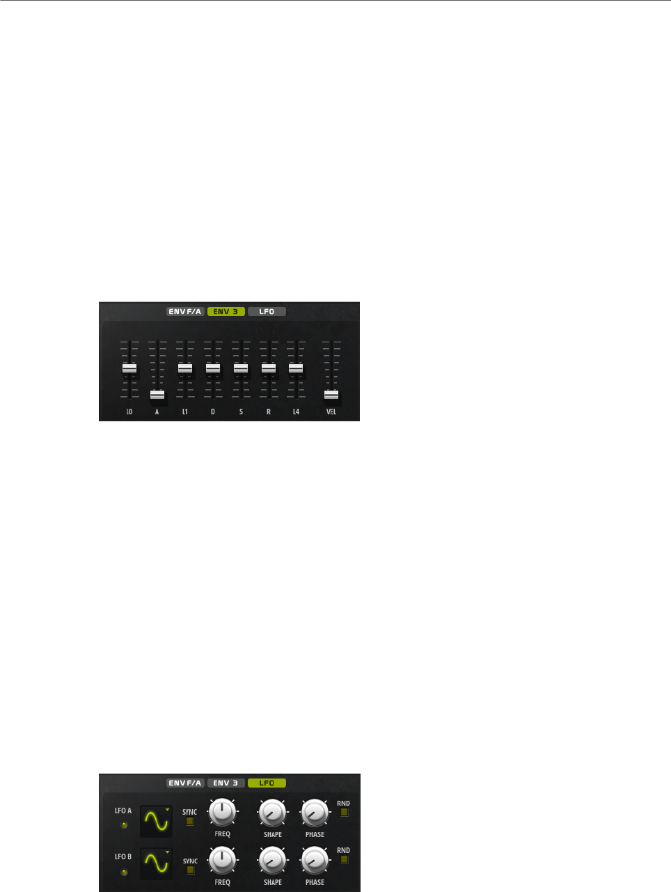
Included Instruments
Anima
169
Decay
Controls the decay time of the amplifier envelope.
Sustain
Controls the sustain level of the amplifier envelope.
Release
Controls the release time of the amplifier envelope.
Env3 Section
The Env3 section provides an additional envelope that can be routed freely in the modulation
matrix. This envelope is bipolar, therefore, it is particularly suited to modulate destinations
like pan or pitch, for example.
The faders below the envelope display set the following parameters:
•L0 sets the start level.
•A sets the attack time.
•L1 sets the attack level.
•D sets the decay time.
•S sets the sustain level.
•R sets the release time.
•L4 sets the end level.
•Vel determines how much the envelope intensity depends on the velocity.
If this fader is set to 0, the envelope is fully applied. Higher values reduce the intensity
for lower velocities.
LFO Section
In the LFO section, you can make settings for the two included LFOs.
LFO Waveform and Shape
•Sine produces smooth modulation, suitable for vibrato or tremolo. Shape
adds additional harmonics to the waveform.

Included Instruments
Anima
170
•Triangle is similar to Sine. Shape continuously changes the triangle
waveform to a trapezoid.
•Saw produces a ramp cycle. Shape continuously changes the waveform
from ramp down to triangle to ramp up.
•Pulse produces stepped modulation, where the modulation switches
abruptly between two values. Shape continuously changes the ratio
between the high and low state of the waveform. If Shape is set to 50 %, a
square wave is produced.
•Ramp is similar to the Saw waveform. Shape increasingly puts silence
before the sawtooth ramp up begins.
•Log produces a logarithmic modulation. Shape continuously changes the
logarithmic curvature from negative to positive.
•S & H 1 produces randomly stepped modulation, where each step is
different. Shape puts ramps between the steps and changes the S & H into
a smooth random signal when fully turned right.
•S & H 2 is similar to S & H 1. The steps alternate between random high and
low values. Shape puts ramps between the steps and changes the S & H
into a smooth random signal when fully turned right.
Sync
If Sync is activated, the frequency is set in fractions of beats.
Freq
Controls the frequency of the modulation, that is, the speed of the LFO.
Phase
Sets the initial phase of the waveform when the LFO is retriggered.
Sync
If Sync is activated, the frequency is set in fractions of beats.
Freq
Controls the frequency of the modulation, that is, the speed of the LFO.
Phase
Sets the initial phase of the waveform when the LFO is retriggered.
Rnd (Random Phase)
If this button is activated, each note starts with a randomized start phase.
NOTE
The Phase control cannot be used if Rnd is activated.
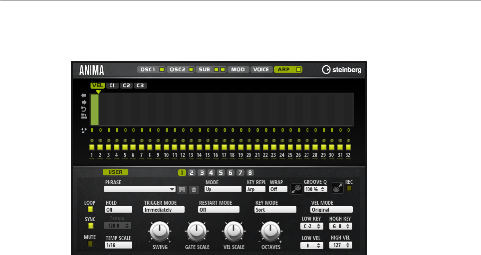
Included Instruments
Skylab
171
Arp Page
This page contains the same parameters as the FlexPhraser.
RELATED LINKS
FlexPhraser on page 76
Skylab
The Skylab synth is an instrument that produces a wide range of sounds that are perfectly
suited to create cinematic or ambient soundtracks. It comes with a large number of multi-
samples that provide a variety of evolving pads and soundscapes as well as typical orchestral
sounds like strings, brass, and choirs, allowing you to create huge and epic sounds.
Furthermore, percussive sample sets of orchestral percussion and taikos are available that
can be used with the integrated arpeggiator to create rhythmic patterns, for example.
Skylab’s oscillator section can be switched between Sample Mode and Grain Mode.
Grain Mode uses granular synthesis with up to eight grain streams, which allows you to
produce even more variations of the source samples. The oscillator is followed by a multi-
mode filter that offers a large number of different filter shapes. The filter can be modulated
by modulation sources like the keyboard, velocity, and LFO, but also by the controller lanes
of the step sequencer, for example. Skylab includes two monophonic LFOs that can be
synchronized to the host tempo and allow you to modulate a large number of modulation
destinations using the modulation matrix. In addition, a third envelope is included that can be
assigned to destinations like Pitch, Pan, or Wavetable parameters in the modulation matrix.
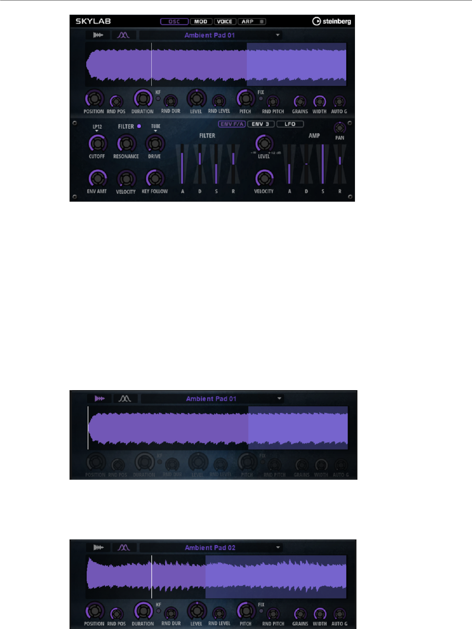
Included Instruments
Skylab
172
Skylab contains four pages: Osc, Mod, Voice, and Arp. To show the settings for a page, click
the corresponding page button.
The button for the Arp page also contains an On/Off button for the arpeggiator.
Osc Page
On this page, you can specify whether you want to use a sample or a grain oscillator and
make settings for the oscillator.
Sample Mode
In Sample Mode, you can load different multi-samples. These samples are played back
normally.
Grain Mode
In Grain Mode, Skylab uses a grain oscillator for playback.

Included Instruments
Skylab
173
Position
You can set the playback position of the grains manually. For example, at a
setting of 50 %, the playback position is in the middle of the sample. The playback
position is updated with every new grain.
Random Position
Selects a random playback position within a specific range around the current
position. At a setting of 100 %, the playback position jumps to a random position
between the start and the end of the sample.
Duration
Increases the grain period by a factor ranging from 1 to 1000.
For very short grains, the sound gets the pitch of the frequency at which the
grains repeat. For grains longer than 30 ms, the sound gets the pitch of the
original sample.
Random Duration
Sets the random grain duration. This duration is calculated at the start of a new
grain.
Duration Key Follow
Determines how the grain duration changes with the notes you play. It is mostly
used with short durations. Longer durations sound with the original pitch of the
sample and therefore do not need to follow the keyboard.
Pitch
Allows you to specify an interval between -12 and +12 semitones. The grains are
played randomly at their original pitch, or are transposed according to the pitch
interval. This parameter is suited for longer grain durations.
Random Pitch
Sets the random pitch range in semitones and cents. At a setting of +12, the
random pitch values lie between -12 and +12 semitones. This parameter can be
used to enrich the sound.
Level
Adjusts the overall level of the grain oscillator. When you increase the number
of grains, it might become necessary to lower the oscillator level. When you play
back a very quiet portion of a sample, you can use this control to raise the level.
Random Level
Sets a random level for each new grain. At a setting of 100 %, the level varies
between a factor of 0 and 2 of the original level.
Width
Narrows the stereo width of the grain oscillator. It is applied after the grain
oscillator and does not affect the stereo width of the actual sample. At a setting
of 0 %, the output of the grain oscillator is monophonic.
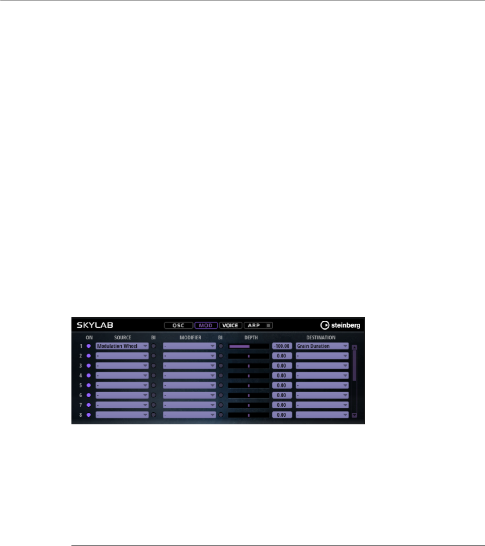
Included Instruments
Skylab
174
Auto Gain
Allows you to automatically adjust the level of grains using quieter sample parts.
This way, you get a more homogeneous signal and you can use a quiet part of a
sample as source.
Grains
Allows you to specify the number of grains, from 1 to 8. For example, with a
setting of 4, you get 4 grains per period of the grain duration.
To hear the effect of this setting, you have to play a new note.
Fixed Pitch
Plays the sample at a fixed pitch.
• If this button is activated, the sample follows the pitch of the keyboard.
The root key is C3.
• If this button is deactivated, the sample plays at its original pitch, and any
pitch modulations for the zone have no effect.
Mod Page
The Mod page contains the modulation matrix.
The modulation matrix offers you up to 16 freely assignable modulations, each with a source,
a modifier, and a destination with adjustable depth. The polarity of each source and each
modifier can be switched between unipolar and bipolar.
Creating Modulations
You create modulations by selecting a source, a modifier, and a destination from the pop-up
menus in the modulation matrix.
PROCEDURE
1. Click the modulation Source field and select the modulation source.
2. Optional: Click in the modulation Modifier field and select the parameter that you want
to use to modify the modulation.
This modifier is used to scale the output of the modulation source.
3. Optional: Specify whether you want the Source and Modifier parameters to be unipolar
or bipolar.
4. Set the modulation intensity with the Depth parameter.

Included Instruments
Skylab
175
5. Click in the modulation Destination field and select the parameter that you want to
modulate.
Modulation Matrix Parameters
Modulation Sources and Modulation Modifiers
The following options are available as modulation sources and as modulation modifiers.
LFO A/B
The LFOs A and B produce cyclic modulation signals.
Amp Envelope
The amplifier envelope. The shape of the envelope determines the modulation
signal.
Filter Envelope
The filter envelope. The shape of the envelope determines the modulation signal.
Env 3
A freely assignable envelope. It is suited for pan or pitch modulation, for example.
Key Follow
This produces an exponential modulation signal derived from the MIDI note
number. Exponential means this source works with destinations such as Pitch or
Cutoff.
Note-on Velocity
Note-on velocity can be used as modulation signal.
Note-on Vel Squared
The squared version of Note-on Velocity. The harder you press the key, the higher
the modulation values.
Pitchbend
The position of the pitchbend wheel can be used as modulation signal.
Modulation Wheel
The position of the modulation wheel can be used as modulation signal.
Aftertouch
Aftertouch can be used as modulation signal. Some MIDI keyboards cannot send
aftertouch messages. However, most sequencer software is able to produce such
messages.
Arp Controller 1–3
The 3 controllers available on this submenu correspond to the three controller
lanes on the Arp page.

Included Instruments
Skylab
176
Bus 1–8
Modulations that are sent to one of the eight busses can be reused as sources.
This way, you can combine several modulations to produce more complex
signals.
Quick Control 1–8
The quick controls can be used as modulation signal.
Unipolar vs. Bipolar Sources
The polarity of a modulation source specifies the value range that it produces. Unipolar
sources modulate between 0 and +1. Bipolar sources modulate between -1 and +1.
• To change the polarity of a modulation source or modifier from unipolar to bipolar,
activate its Bipolar button.
Modulation Destinations
Pitch
Modulates the pitch. For example, assign one of the LFOs to create a vibrato
effect. If Pitch is selected, the modulation depth is set in semitones.
Cutoff
Modulates the filter cutoff.
Resonance
Modulates the filter resonance. Resonance changes the character of the filter.
For example, to accent the filter the harder you hit a key, assign Velocity to
Resonance.
Distortion
Modulates the filter distortion.
Level
This modulation adds to the level setting. It can be used to create level offsets
using the mod wheel, for example.
Volume
Modulates the gain. The volume modulation multiplies with the level.
Pan
Modulates the position of the sound in the panorama.
Grain Position
Modulates the playback position. The modulation is not continuous, but it is
updated at the start of each grain.

Included Instruments
Skylab
177
Grain Duration
Modulates the grain duration, that is, the frequency at which the grains repeat.
The maximum modulation range at a modulation depth of 100 % is -5 to +5
octaves.
Grain Pitch
Modulates the pitch of a grain. The modulation is not continuous, but it is updated
at the start of a new grain. For continuous pitch modulation, use Pitch instead of
Grain Pitch as destination and make sure that Follow Zone Pitch is activated in
the grain oscillator.
Grain Formant
Modulates the pitch of the source sample independently from the grain duration.
This results in formant shifting for short durations.
Grain Level
Modulates the grain level. The modulation is not continuous, but it is updated at
the start of each new grain.
Amp Env Attack
Modulates the attack time of the amplitude envelope. This modulation
destination cannot be modulated continuously. The time is updated only when the
segment starts.
Amp Env Decay
Modulates the decay time of the amplitude envelope. This modulation destination
cannot be modulated continuously. The time is updated only when the segment
starts.
Amp Env Sustain
Modulates the sustain level of the amplitude envelope. This modulation
destination cannot be modulated continuously. The level is updated only when the
segment starts.
Amp Env Release
Modulates the release time of the amplitude envelope. This modulation
destination cannot be modulated continuously. The time is updated only when the
segment starts.
Filter Env Attack
Modulates the attack time of the filter envelope. This modulation destination
cannot be modulated continuously. The time is updated only when the segment
starts.
Filter Env Decay
Modulates the decay time of the filter envelope. This modulation destination
cannot be modulated continuously. The time is updated only when the segment
starts.

Included Instruments
Skylab
178
Filter Env Sustain
Modulates the sustain level of the filter envelope. This modulation destination
cannot be modulated continuously. The level is updated only when the segment
starts.
Filter Env Release
Modulates the release time of the filter envelope. This modulation destination
cannot be modulated continuously. The time is updated only when the segment
starts.
Env 3 Start Level
Modulates the start level of the user-definable envelope 3, that is, the level
of the first envelope node. This modulation destination cannot be modulated
continuously. The level is updated only when the segment starts.
Env 3 Attack
Modulates the attack time of the user-definable envelope 3. This modulation
destination cannot be modulated continuously. The time is updated only when the
segment starts.
Env 3 Attack Level
Modulates the attack level of the user-definable envelope 3, that is, the level of
the second envelope node. This modulation destination cannot be modulated
continuously. The level is updated only when the segment starts.
Env 3 Decay
Modulates the decay time of the user-definable envelope 3. This modulation
destination cannot be modulated continuously. The time is updated only when the
segment starts.
Env 3 Sustain
Modulates the sustain level of the user-definable envelope 3. This modulation
destination cannot be modulated continuously. The level is updated only when the
segment starts.
Env 3 Release
Modulates the release time of the user-definable envelope 3. This modulation
destination cannot be modulated continuously. The time is updated only when the
segment starts.
Env 3 Release Level
Modulates the release level of the user-definable envelope 3, that is, the
last user envelope node. This modulation destination cannot be modulated
continuously. The level is updated only when the segment starts.
Bus 1-8
You can send any modulation to one of the 8 busses, for example, to produce
more complex modulation signals. Select the bus that you want to send the
signals to as a destination. To use the modulation that was sent to a bus, assign
the corresponding bus as a modulation source.
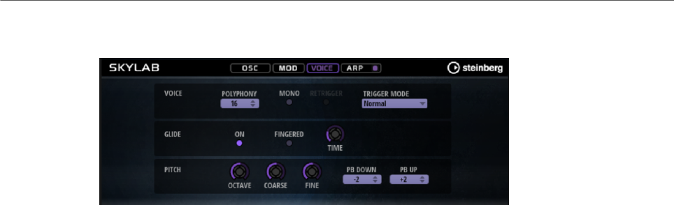
Included Instruments
Skylab
179
Voice Page
Voice Section
Polyphony
If Mono mode is deactivated, you can use this parameter to specify how many
notes can be played simultaneously.
Mono
Activates monophonic playback.
Retrigger
This option is only available in Mono mode. If Retrigger is activated, a note that
was stolen by another note is retriggered if you still hold the stolen note when
you release the new one.
This way, you can play trills by holding one note and quickly and repeatedly
pressing and releasing another note, for example.
Trigger Mode
Defines the trigger behavior for new notes.
•Normal triggers a new note when the previous note gets stolen. The
sample and the envelope of the new note are triggered from the start.
To minimize discontinuities, use the Fade Out parameter of the zone.
•Resume does not always trigger a new note.
If the new note stays within the same zone, the envelope is retriggered, but
resumes at the level of the stolen note. The pitch of the zone is set to the
new note.
If the new note plays in a different zone, the sample and the envelope of the
new note are triggered from the start.
•Legato does not always trigger a new note.
If the new note stays within the same zone, the envelope keeps running.
The pitch of the zone is set to the new note.
If the new note plays in a different zone, the sample and the envelope of the
new note are triggered from the start.
•Resume Keeps Zone does not trigger a new note upon note stealing. The
envelope resumes at the level of the stolen note and the pitch of the zone is
set to the new note, even if the new note plays in a different zone.

Included Instruments
Skylab
180
•Legato Keeps Zone does not trigger a new note upon note stealing. The
envelope keeps running and the pitch of the zone is set to the new note,
even if the new note plays in a different zone.
Glide Section
Glide
Allows you to bend the pitch between notes that follow each other. You achieve
the best results in Mono mode.
Fingered
Activate this parameter to glide the pitch only between notes that are played
legato.
Glide Time
Sets the glide time, that is, the time it takes to bend the pitch from one note to
the next.
Pitch Section
Octave
Adjusts the pitch in octave steps.
Coarse
Adjusts the pitch in semitone steps.
Fine
Adjusts the pitch in cent steps. This allows you to fine-tune the oscillator sound.
Pitchbend Up/Pitchbend Down
Determines the range for the modulation that is applied when you move the
pitchbend wheel.
Filter Section
Filter On/Off
Activates/Deactivates the filter.
Filter Shape
• LP24, 18, 12, and 6 are low-pass filters with 24, 18, 12, and 6 dB/oct.
Frequencies above the cutoff are attenuated.
• BP12 and BP24 are band-pass filters with 12 and 24 dB/oct. Frequencies
below and above the cutoff are attenuated.

Included Instruments
Skylab
181
• HP6+LP18 and HP6+LP12 are combinations of a high-pass filter with 6 dB/
oct and a low-pass filter with 18 and 12 dB/oct, respectively (asymmetric
band-pass filter). Frequencies below and above the cutoff are attenuated.
Attenuation is more pronounced for the frequencies above the cutoff.
• HP12+LP6 and HP18+LP6 are combinations of a high-pass filter with 12
and 18 dB/oct and a low-pass filter with 6 dB/oct (asymmetric band-pass
filter). Frequencies below and above the cutoff are attenuated. Attenuation
is more pronounced for the frequencies below the cutoff.
• HP24, 18, 12, and 6 are high-pass filters with 24, 18, 12, and 6 dB/oct.
Frequencies below the cutoff are attenuated.
• BR12 and BR24 are band-reject filters with 12 and 24 dB/oct. Frequencies
around the cutoff are attenuated.
• BR12+LP6 and BR12+LP12 are combinations of a band-reject filter with 12
dB/oct and a low-pass filter with 6 and 12 dB/oct, respectively. Frequencies
around and above the cutoff are attenuated.
• BP12+BR12 is a band-pass filter with 12 dB/oct plus a band-reject filter
with 12 dB/oct. Frequencies below, above, and around the cutoff are
attenuated.
• HP6+BR12 and HP12+BR12 are combinations of a high-pass filter with 6
and 12 dB/oct and a band-reject filter with 12 dB/oct. Frequencies below
and around the cutoff are attenuated.
• AP is an all-pass filter with 18 dB/oct. Frequencies around the cutoff are
attenuated.
• AP+LP6 is an all-pass filter with 18 dB/oct plus a low-pass filter with 6 dB/
oct. Frequencies around and above the cutoff are attenuated.
• HP6+AP is a high-pass filter with 6 dB/oct plus an all-pass filter with 18
dB/oct. Frequencies around and below the cutoff are attenuated.
Cutoff
Controls the cutoff frequency of the filter.
Resonance
Emphasizes the frequencies around the cutoff. At higher settings, the filter self-
oscillates, which results in a ringing tone.
Distortion
Adds distortion to the signal. The following distortion types are available:
•Tube adds warm, tube-like distortion.
•Hard Clip adds bright, transistor-like distortion.
•Bit Reduction adds digital distortion by means of quantization noise.
•Rate Reduction adds digital distortion by means of aliasing.
•Rate Reduction Key Follow adds digital distortion by means of aliasing, but
with Key Follow. The rate reduction follows the keyboard, so the higher you
play, the higher the sample rate.
Envelope Amount
Controls the cutoff modulation from the filter envelope.
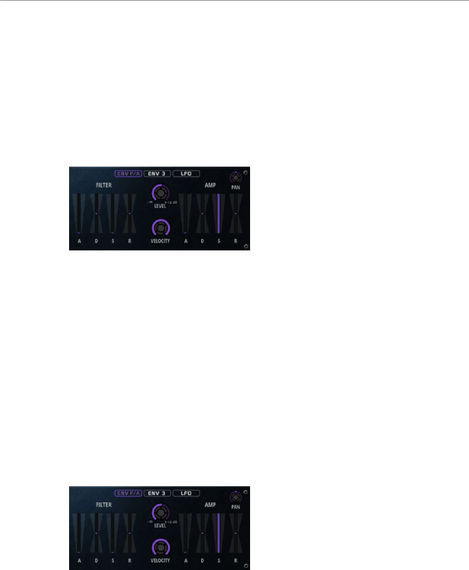
Included Instruments
Skylab
182
Cutoff Velocity
Controls the cutoff modulation from velocity.
Cutoff Key Follow
Adjusts the cutoff modulation using the note number. Increase this parameter
to raise the cutoff with higher notes. At 100 %, the cutoff follows the played pitch
exactly.
Filter Envelope
On the left on the Env F/A tab, you can set up the filter envelope.
Attack
Controls the attack time of the filter envelope.
Decay
Controls the decay time of the filter envelope.
Sustain
Controls the sustain level of the filter envelope.
Release
Controls the release time of the filter envelope.
Amplifier and Amplifier Envelope
On the right of the Env F/A tab, you can make settings for the amplifier and the amplifier
envelope.
Amplifier Parameters
Level
Controls the overall volume of the sound.
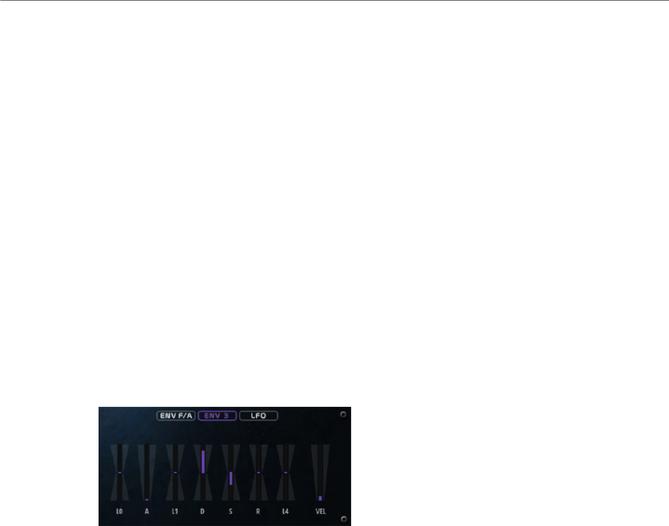
Included Instruments
Skylab
183
Velocity
Controls the level modulation from velocity. At 0, all notes are played with the
same level.
Amplifier Envelope Parameters
Attack
Controls the attack time of the amplifier envelope.
Decay
Controls the decay time of the amplifier envelope.
Sustain
Controls the sustain level of the amplifier envelope.
Release
Controls the release time of the amplifier envelope.
Env3 Section
The faders below the envelope display set the following parameters:
•L0 sets the start level.
•A sets the attack time.
•L1 sets the attack level.
•D sets the decay time.
•S sets the sustain level.
•R sets the release time.
•L4 sets the end level.
•Vel determines how much the envelope intensity depends on the velocity.
If this fader is set to 0, the envelope is fully applied. Higher values reduce the intensity
for lower velocities.

Included Instruments
Skylab
184
LFO Section
In the LFO section, you can make settings for LFO A and LFO B.
LFO Waveform and Shape
•Sine produces smooth modulation, suitable for vibrato or tremolo. Shape
adds additional harmonics to the waveform.
•Triangle is similar to Sine. Shape continuously changes the triangle
waveform to a trapezoid.
•Saw produces a ramp cycle. Shape continuously changes the waveform
from ramp down to triangle to ramp up.
•Pulse produces stepped modulation, where the modulation switches
abruptly between two values. Shape continuously changes the ratio
between the high and low state of the waveform. If Shape is set to 50 %, a
square wave is produced.
•Ramp is similar to the Saw waveform. Shape increasingly puts silence
before the sawtooth ramp up begins.
•Log produces a logarithmic modulation. Shape continuously changes the
logarithmic curvature from negative to positive.
•S & H 1 produces randomly stepped modulation, where each step is
different. Shape puts ramps between the steps and changes the S & H into
a smooth random signal when fully turned right.
•S & H 2 is similar to S & H 1. The steps alternate between random high and
low values. Shape puts ramps between the steps and changes the S & H
into a smooth random signal when fully turned right.
Sync
If Sync is activated, the frequency is set in fractions of beats.
Freq
Controls the frequency of the modulation, that is, the speed of the LFO.
Phase
Sets the initial phase of the waveform when the LFO is retriggered.
Rnd (Random Phase)
If this button is activated, each note starts with a randomized start phase.
NOTE
The Phase control cannot be used if Rnd is activated.
Included Instruments
Raven
185
Arp Page
This page contains the same parameters as the FlexPhraser.
RELATED LINKS
FlexPhraser on page 76
Raven
Raven provides the sound of a classical Italian concert grand with six velocity layers and
adjustable sustain resonances. Its Tone control allows you to adapt the tonal range from very
soft romantic to more intense colors. In addition, you can modify the character of the note-off
behavior by adding a dedicated note-off layer.
Tone
Raven comes with 6 different velocity layers. The Tone control allows you to
specify how these layers are used.
• If the Tone control is in middle position, different input velocities trigger all
6 layers.

Included Instruments
Eagle
186
• If you turn the knob to the left, the number of hard velocity layers that are
used in the sound is reduced, that is, the sound becomes softer.
• If you turn the knob to the right, the number of soft velocity layers that are
used is reduced, that is, the sound becomes harder.
NOTE
The Tone control is independent from the influence that the velocity has on the
level of the piano. That means that you can always play the entire level range,
even with the softest or the hardest layer.
Dynamics – Curve
Allows you to specify how the input velocity is affecting the level of the piano.
The curve that is used by this control goes from linear to exponential/negative
exponential. The curve display on the right reflects the current setting.
Dynamics – Minimum Level
Specifies the minimum level for the note that is playing the lowest MIDI velocity.
This allows you to simulate the behavior of real pianos where you cannot play a
note without a minimum amount of pressure. If you set this control to the lowest
setting, you get a behavior that is more common with electronic instruments.
Sustain Resonance
Allows you to decide whether or not to use the additional sustain resonance layer
of the piano.
If this option is activated, the sustain resonance layers are played when the
sustain pedal is held and notes are played. You can adjust the level of the
resonance layer with the dial on the right.
NOTE
The piano also allows for repedaling, which means that the sustain resonances
will also be blended in when the sustain pedal is pressed again shortly after
notes have been played.
If you do not want to use the sustain resonance layers, deactivate this option to
save CPU power.
Note Off
Allows you to decide whether or not to use an additional note-off layer.
If this option is deactivated, the sound of the piano stops faster when a key is
released. If this option is activated, the release is slightly longer and smoother.
Polyphony
Determines the number of notes that can be played before notes are stolen.
Eagle
Eagle provides the sound of a classical German concert grand with 12 velocity layers and
adjustable sustain resonances. Its Tone control allows you to adapt the tonal range from very
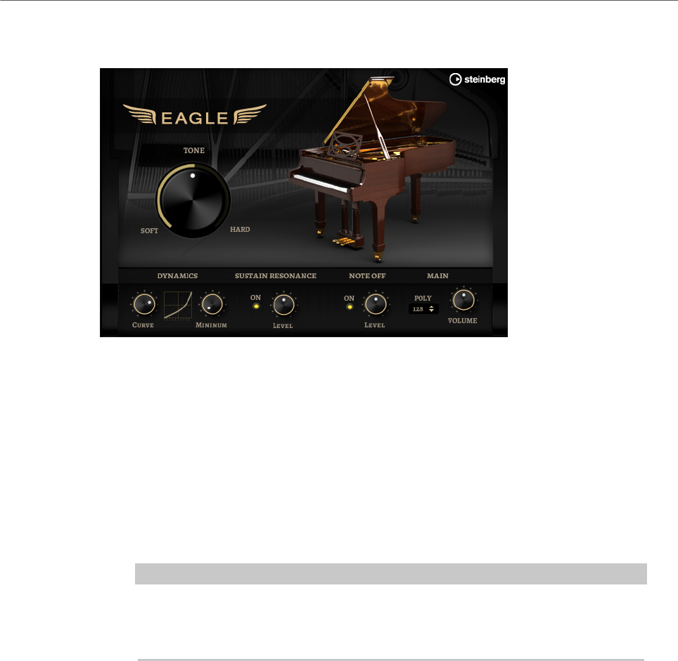
Included Instruments
Eagle
187
soft romantic to more intense colors. In addition, you can modify the character of the note-off
behavior by adding a dedicated note-off layer.
Tone
Eagle comes with 12 different velocity layers. The Tone control allows you to
specify how these layers are used.
• If the Tone control is in middle position, different input velocities trigger all
12 layers.
• If you turn the knob to the left, the number of hard velocity layers that are
used in the sound is reduced, that is, the sound becomes softer.
• If you turn the knob to the right, the number of soft velocity layers that are
used is reduced, that is, the sound becomes harder.
NOTE
The Tone control is independent from the influence that the velocity has on the
level of the piano. That means that you can always play the entire level range,
even with the softest or the hardest layer.
Dynamics – Curve
Allows you to specify how the input velocity is affecting the level of the piano.
The curve that is used by this control goes from linear to exponential/negative
exponential. The curve display on the right reflects the current setting.
Dynamics – Minimum Level
Specifies the minimum level for the note that is playing the lowest MIDI velocity.
This allows you to simulate the behavior of real pianos where you cannot play a
note without a minimum amount of pressure. If you set this control to the lowest
setting, you get a behavior that is more common with electronic instruments.
Sustain Resonance
Allows you to decide whether or not to use the additional sustain resonance layer
of the piano.

Included Instruments
Hot Brass
188
If this option is activated, the sustain resonance layers are played when the
sustain pedal is held and notes are played. You can adjust the level of the
resonance layer with the dial on the right.
NOTE
The piano also allows for repedaling, which means that the sustain resonances
will also be blended in when the sustain pedal is pressed again shortly after
notes have been played.
If you do not want to use the sustain resonance layers, deactivate this option to
save CPU power.
Note Off
Allows you to decide whether or not to use an additional note-off layer.
If this option is deactivated, the sound of the piano stops faster when a key is
released. If this option is activated, the release is slightly longer and smoother.
Polyphony
Determines the number of notes that can be played before notes are stolen.
Hot Brass
Hot Brass delivers a broad range of brass sounds and articulations suited for rock, soul,
funk, and other music styles that need sharp and accentuated brass tone colors. This
instrument is particularly suited to play concise licks and riffs.
The instrument’s sample oscillators are followed by a synthesis section with a flexible filter
where you can modify the sounds further. With the FlexPhraser functionality on the Arp
page, you can play typical brass phrases and licks with a single note on your keyboard.
Hot Brass contains four pages: Main, Mod, Voice, and Arp. To show the settings for a page,
click the corresponding page button.
The button for the Arp page also contains an On/Off button for the arpeggiator.
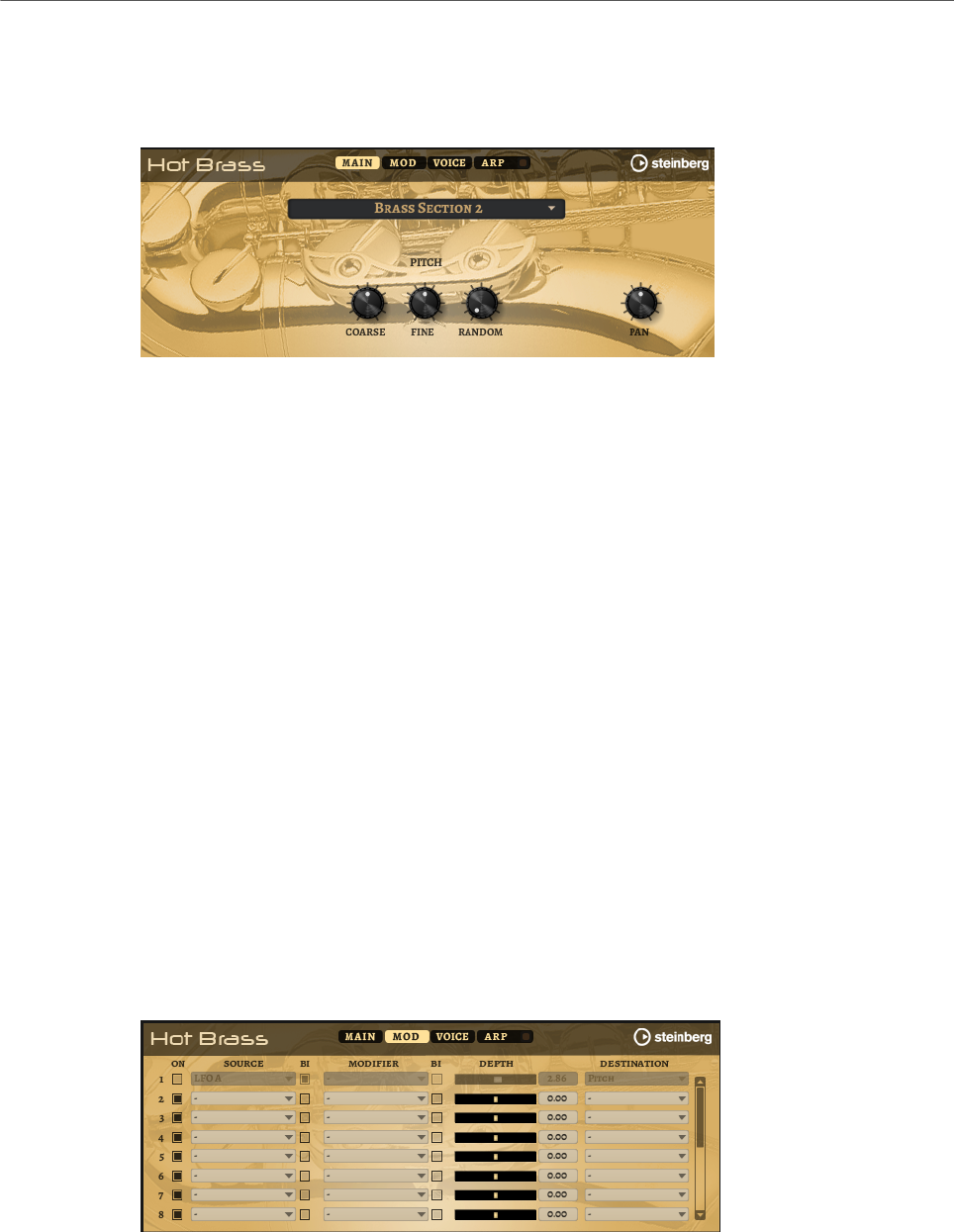
Included Instruments
Hot Brass
189
Main Page
The Main page allows you to select the sample for Hot Brass and to make basic pitch
settings.
Select Samples
Allows you to choose from a range of included samples. Hot Brass provides three
differently mixed sections and a pure saxophone section. You can add additional
authenticity to your play using the included falls, growls, doits, shakes, and
staccato articulations.
Coarse
Adjusts the pitch in semitone steps.
Fine
Allows you to fine-tune the pitch in cent steps.
Random Pitch
Allows you to randomly offset the pitch with each played note. Higher values
cause stronger variations. At the maximum setting, the random offsets can vary
from -60 cents to +60 cents.
Pan
Defines the position of the instrument in the stereo panorama
Mod Page
The Mod page contains the modulation matrix.
The modulation matrix offers you up to 16 freely assignable modulations, each with a source,
a modifier, and a destination with adjustable depth. The polarity of each source and each
modifier can be switched between unipolar and bipolar.

Included Instruments
Hot Brass
190
Creating Modulations
You create modulations by selecting a source, a modifier, and a destination from the pop-up
menus in the modulation matrix.
PROCEDURE
1. Click the modulation Source field and select the modulation source.
2. Optional: Click in the modulation Modifier field and select the parameter that you want
to use to modify the modulation.
This modifier is used to scale the output of the modulation source.
3. Optional: Specify whether you want the Source and Modifier parameters to be unipolar
or bipolar.
4. Set the modulation intensity with the Depth parameter.
5. Click in the modulation Destination field and select the parameter that you want to
modulate.
Modulation Matrix Parameters
Modulation Sources and Modulation Modifiers
The following options are available as modulation sources and as modulation modifiers.
LFO A/B
The LFOs A and B produce cyclic modulation signals.
Amp Envelope
The amplifier envelope. The shape of the envelope determines the modulation
signal.
Filter Envelope
The filter envelope. The shape of the envelope determines the modulation signal.
Env 3
A freely assignable envelope. It is suited for pan or pitch modulation, for example.
Key Follow
This produces an exponential modulation signal derived from the MIDI note
number. Exponential means this source works with destinations such as Pitch or
Cutoff.
Note-on Velocity
Note-on velocity can be used as modulation signal.
Note-on Vel Squared
The squared version of Note-on Velocity. The harder you press the key, the higher
the modulation values.
Pitchbend
The position of the pitchbend wheel can be used as modulation signal.

Included Instruments
Hot Brass
191
Modulation Wheel
The position of the modulation wheel can be used as modulation signal.
Aftertouch
Aftertouch can be used as modulation signal. Some MIDI keyboards cannot send
aftertouch messages. However, most sequencer software is able to produce such
messages.
Arp Controller 1–3
The 3 controllers available on this submenu correspond to the three controller
lanes on the Arp page.
Bus 1–8
Modulations that are sent to one of the eight busses can be reused as sources.
This way, you can combine several modulations to produce more complex
signals.
Quick Control 1–8
The quick controls can be used as modulation signal.
Unipolar vs. Bipolar Sources
The polarity of a modulation source specifies the value range that it produces. Unipolar
sources modulate between 0 and +1. Bipolar sources modulate between -1 and +1.
• To change the polarity of a modulation source or modifier from unipolar to bipolar,
activate its Bipolar button.
Modulation Destinations
Pitch
Modulates the pitch. For example, assign one of the LFOs to create a vibrato
effect. If Pitch is selected, the modulation depth is set in semitones.
Cutoff
Modulates the filter cutoff.
Resonance
Modulates the filter resonance. Resonance changes the character of the filter.
For example, to accent the filter the harder you hit a key, assign Velocity to
Resonance.
Distortion
Modulates the filter distortion.
Level
This modulation adds to the level setting. It can be used to create level offsets
using the mod wheel, for example.

Included Instruments
Hot Brass
192
Volume
Modulates the gain. The volume modulation multiplies with the level.
Pan
Modulates the position of the sound in the panorama.
Amp Env Attack
Modulates the attack time of the amplitude envelope. This modulation
destination cannot be modulated continuously. The time is updated only when the
segment starts.
Amp Env Decay
Modulates the decay time of the amplitude envelope. This modulation destination
cannot be modulated continuously. The time is updated only when the segment
starts.
Amp Env Sustain
Modulates the sustain level of the amplitude envelope. This modulation
destination cannot be modulated continuously. The level is updated only when the
segment starts.
Amp Env Release
Modulates the release time of the amplitude envelope. This modulation
destination cannot be modulated continuously. The time is updated only when the
segment starts.
Filter Env Attack
Modulates the attack time of the filter envelope. This modulation destination
cannot be modulated continuously. The time is updated only when the segment
starts.
Filter Env Decay
Modulates the decay time of the filter envelope. This modulation destination
cannot be modulated continuously. The time is updated only when the segment
starts.
Filter Env Sustain
Modulates the sustain level of the filter envelope. This modulation destination
cannot be modulated continuously. The level is updated only when the segment
starts.
Filter Env Release
Modulates the release time of the filter envelope. This modulation destination
cannot be modulated continuously. The time is updated only when the segment
starts.
Env 3 Start Level
Modulates the start level of the user-definable envelope 3, that is, the level
of the first envelope node. This modulation destination cannot be modulated
continuously. The level is updated only when the segment starts.

Included Instruments
Hot Brass
193
Env 3 Attack
Modulates the attack time of the user-definable envelope 3. This modulation
destination cannot be modulated continuously. The time is updated only when the
segment starts.
Env 3 Attack Level
Modulates the attack level of the user-definable envelope 3, that is, the level of
the second envelope node. This modulation destination cannot be modulated
continuously. The level is updated only when the segment starts.
Env 3 Decay
Modulates the decay time of the user-definable envelope 3. This modulation
destination cannot be modulated continuously. The time is updated only when the
segment starts.
Env 3 Sustain
Modulates the sustain level of the user-definable envelope 3. This modulation
destination cannot be modulated continuously. The level is updated only when the
segment starts.
Env 3 Release
Modulates the release time of the user-definable envelope 3. This modulation
destination cannot be modulated continuously. The time is updated only when the
segment starts.
Env 3 Release Level
Modulates the release level of the user-definable envelope 3, that is, the
last user envelope node. This modulation destination cannot be modulated
continuously. The level is updated only when the segment starts.
Bus 1-8
You can send any modulation to one of the 8 busses, for example, to produce
more complex modulation signals. Select the bus that you want to send the
signals to as a destination. To use the modulation that was sent to a bus, assign
the corresponding bus as a modulation source.
Voice Page
Polyphony
If Mono mode is deactivated, you can use this parameter to specify how many
notes can be played simultaneously.

Included Instruments
Hot Brass
194
Mono
Activates monophonic playback.
Retrigger
This option is only available in Mono mode. If Retrigger is activated, a note that
was stolen by another note is retriggered if you still hold the stolen note when
you release the new one.
This way, you can play trills by holding one note and quickly and repeatedly
pressing and releasing another note, for example.
Trigger Mode
Defines the trigger behavior for new notes.
•Normal triggers a new note when the previous note gets stolen. The
sample and the envelope of the new note are triggered from the start.
To minimize discontinuities, use the Fade Out parameter of the zone.
•Resume does not always trigger a new note.
If the new note stays within the same zone, the envelope is retriggered, but
resumes at the level of the stolen note. The pitch of the zone is set to the
new note.
If the new note plays in a different zone, the sample and the envelope of the
new note are triggered from the start.
•Legato does not always trigger a new note.
If the new note stays within the same zone, the envelope keeps running.
The pitch of the zone is set to the new note.
If the new note plays in a different zone, the sample and the envelope of the
new note are triggered from the start.
•Resume Keeps Zone does not trigger a new note upon note stealing. The
envelope resumes at the level of the stolen note and the pitch of the zone is
set to the new note, even if the new note plays in a different zone.
•Legato Keeps Zone does not trigger a new note upon note stealing. The
envelope keeps running and the pitch of the zone is set to the new note,
even if the new note plays in a different zone.
Glide
Allows you to bend the pitch between notes that follow each other. You achieve
the best results in Mono mode.
Fingered
Activate this parameter to glide the pitch only between notes that are played
legato.
Glide Time
Sets the glide time, that is, the time it takes to bend the pitch from one note to
the next.
Pitchbend Up/Pitchbend Down
Determines the range for the modulation that is applied when you move the
pitchbend wheel.
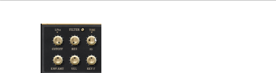
Included Instruments
Hot Brass
195
Filter Section
Filter On/Off
Activates/Deactivates the filter.
Filter Shape
• LP24, 18, 12, and 6 are low-pass filters with 24, 18, 12, and 6 dB/oct.
Frequencies above the cutoff are attenuated.
• BP12 and BP24 are band-pass filters with 12 and 24 dB/oct. Frequencies
below and above the cutoff are attenuated.
• HP6+LP18 and HP6+LP12 are combinations of a high-pass filter with 6 dB/
oct and a low-pass filter with 18 and 12 dB/oct, respectively (asymmetric
band-pass filter). Frequencies below and above the cutoff are attenuated.
Attenuation is more pronounced for the frequencies above the cutoff.
• HP12+LP6 and HP18+LP6 are combinations of a high-pass filter with 12
and 18 dB/oct and a low-pass filter with 6 dB/oct (asymmetric band-pass
filter). Frequencies below and above the cutoff are attenuated. Attenuation
is more pronounced for the frequencies below the cutoff.
• HP24, 18, 12, and 6 are high-pass filters with 24, 18, 12, and 6 dB/oct.
Frequencies below the cutoff are attenuated.
• BR12 and BR24 are band-reject filters with 12 and 24 dB/oct. Frequencies
around the cutoff are attenuated.
• BR12+LP6 and BR12+LP12 are combinations of a band-reject filter with 12
dB/oct and a low-pass filter with 6 and 12 dB/oct, respectively. Frequencies
around and above the cutoff are attenuated.
• BP12+BR12 is a band-pass filter with 12 dB/oct plus a band-reject filter
with 12 dB/oct. Frequencies below, above, and around the cutoff are
attenuated.
• HP6+BR12 and HP12+BR12 are combinations of a high-pass filter with 6
and 12 dB/oct and a band-reject filter with 12 dB/oct. Frequencies below
and around the cutoff are attenuated.
• AP is an all-pass filter with 18 dB/oct. Frequencies around the cutoff are
attenuated.
• AP+LP6 is an all-pass filter with 18 dB/oct plus a low-pass filter with 6 dB/
oct. Frequencies around and above the cutoff are attenuated.
• HP6+AP is a high-pass filter with 6 dB/oct plus an all-pass filter with 18
dB/oct. Frequencies around and below the cutoff are attenuated.
Cutoff
Controls the cutoff frequency of the filter.
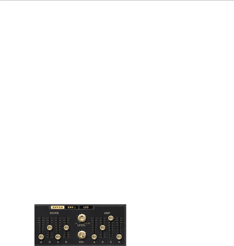
Included Instruments
Hot Brass
196
Resonance
Emphasizes the frequencies around the cutoff. At higher settings, the filter self-
oscillates, which results in a ringing tone.
Distortion
Adds distortion to the signal. The following distortion types are available:
•Tube adds warm, tube-like distortion.
•Hard Clip adds bright, transistor-like distortion.
•Bit Reduction adds digital distortion by means of quantization noise.
•Rate Reduction adds digital distortion by means of aliasing.
•Rate Reduction Key Follow adds digital distortion by means of aliasing, but
with Key Follow. The rate reduction follows the keyboard, so the higher you
play, the higher the sample rate.
Envelope Amount
Controls the cutoff modulation from the filter envelope.
Cutoff Velocity
Controls the cutoff modulation from velocity.
Cutoff Key Follow
Adjusts the cutoff modulation using the note number. Increase this parameter
to raise the cutoff with higher notes. At 100 %, the cutoff follows the played pitch
exactly.
Filter Envelope
On the left on the Env F/A tab, you can set up the filter envelope.
Attack
Controls the attack time of the filter envelope.
Decay
Controls the decay time of the filter envelope.
Sustain
Controls the sustain level of the filter envelope.
Release
Controls the release time of the filter envelope.
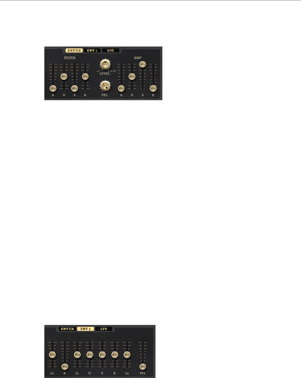
Included Instruments
Hot Brass
197
Amplifier and Amplifier Envelope
On the right of the Env F/A tab, you can make settings for the amplifier and the amplifier
envelope.
Amplifier Parameters
Level
Controls the overall volume of the sound.
Velocity
Controls the level modulation from velocity. At 0, all notes are played with the
same level.
Amplifier Envelope Parameters
Attack
Controls the attack time of the amplifier envelope.
Decay
Controls the decay time of the amplifier envelope.
Sustain
Controls the sustain level of the amplifier envelope.
Release
Controls the release time of the amplifier envelope.
Env3 Section
The faders below the envelope display set the following parameters:
•L0 sets the start level.
•A sets the attack time.
•L1 sets the attack level.
•D sets the decay time.
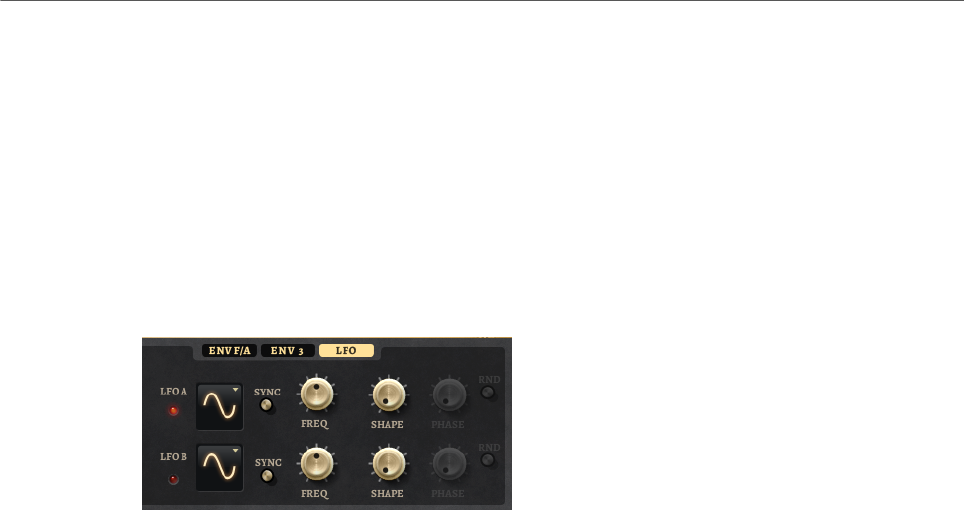
Included Instruments
Hot Brass
198
•S sets the sustain level.
•R sets the release time.
•L4 sets the end level.
•Vel determines how much the envelope intensity depends on the velocity.
If this fader is set to 0, the envelope is fully applied. Higher values reduce the intensity
for lower velocities.
LFO Section
In the LFO section, you can make settings for LFO A and LFO B.
LFO Waveform and Shape
•Sine produces smooth modulation, suitable for vibrato or tremolo. Shape
adds additional harmonics to the waveform.
•Triangle is similar to Sine. Shape continuously changes the triangle
waveform to a trapezoid.
•Saw produces a ramp cycle. Shape continuously changes the waveform
from ramp down to triangle to ramp up.
•Pulse produces stepped modulation, where the modulation switches
abruptly between two values. Shape continuously changes the ratio
between the high and low state of the waveform. If Shape is set to 50 %, a
square wave is produced.
•Ramp is similar to the Saw waveform. Shape increasingly puts silence
before the sawtooth ramp up begins.
•Log produces a logarithmic modulation. Shape continuously changes the
logarithmic curvature from negative to positive.
•S & H 1 produces randomly stepped modulation, where each step is
different. Shape puts ramps between the steps and changes the S & H into
a smooth random signal when fully turned right.
•S & H 2 is similar to S & H 1. The steps alternate between random high and
low values. Shape puts ramps between the steps and changes the S & H
into a smooth random signal when fully turned right.
Sync
If Sync is activated, the frequency is set in fractions of beats.
Freq
Controls the frequency of the modulation, that is, the speed of the LFO.
Phase
Sets the initial phase of the waveform when the LFO is retriggered.
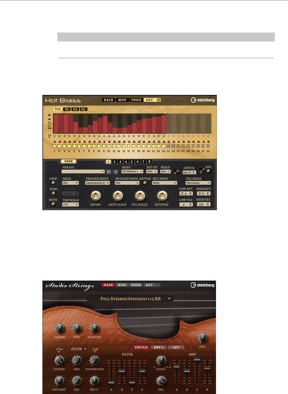
Included Instruments
Studio Strings
199
Rnd (Random Phase)
If this button is activated, each note starts with a randomized start phase.
NOTE
The Phase control cannot be used if Rnd is activated.
Arp Page
This page contains the same parameters as the FlexPhraser.
RELATED LINKS
FlexPhraser on page 76
Studio Strings
Studio Strings delivers a broad range of string sounds and articulations comprising solo
strings, small chamber, and full orchestra sections.
The instrument’s sample oscillators are followed by a synthesis section with a flexible
filter where you can modify the sounds further. With the FlexPhraser functionality on the
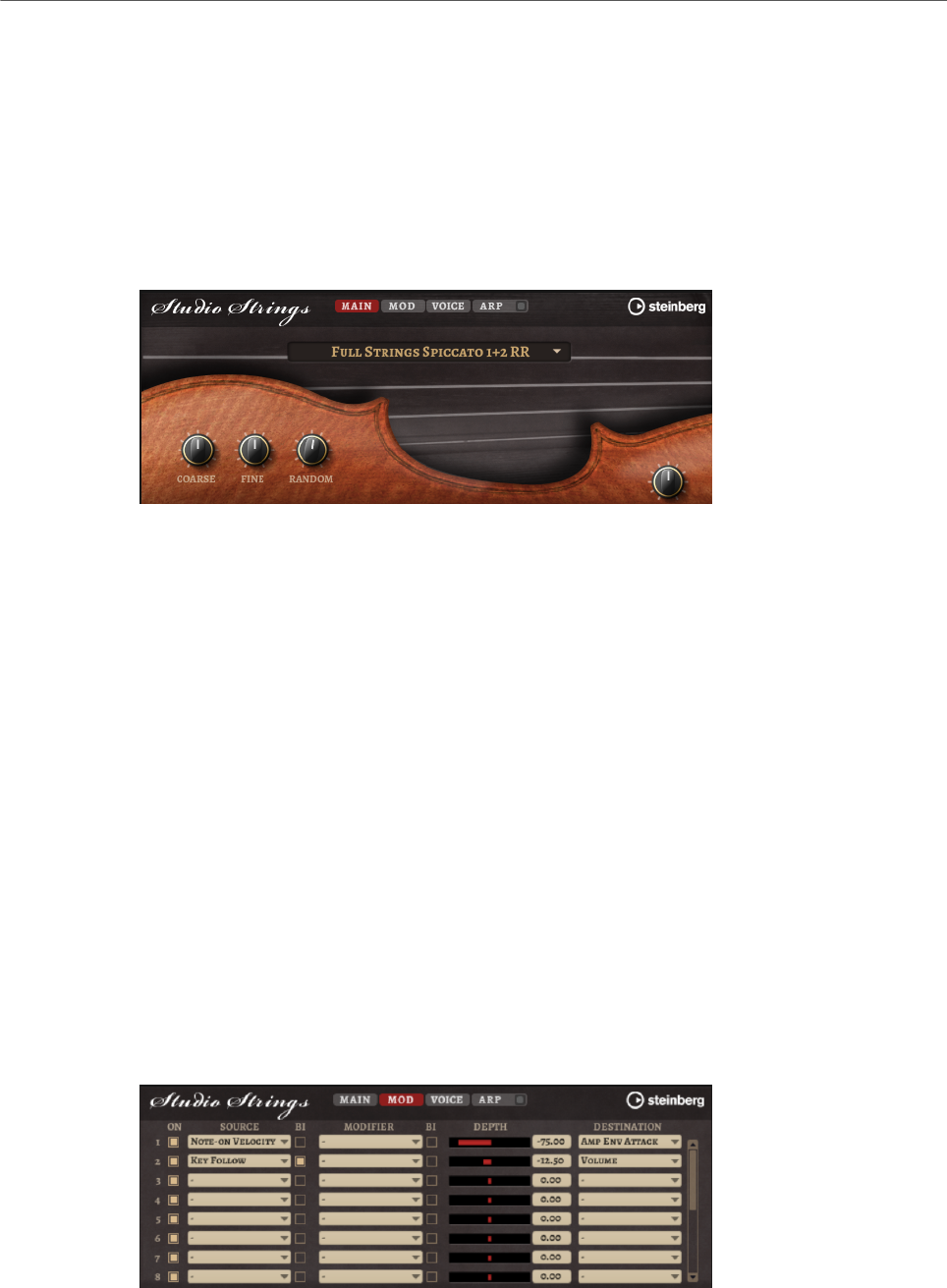
Included Instruments
Studio Strings
200
Arp page, you can play typical phrases with a single note on your keyboard. Studio Strings
contains four pages: Main, Mod, Voice, and Arp. To show the settings for a page, click the
corresponding page button.
The button for the Arp page also contains an On/Off button for the arpeggiator.
Main Page
The Main page allows you to select the sample for Studio Strings and to make basic pitch
settings.
Select Samples
Allows you to choose from a range of included samples.
Coarse
Adjusts the pitch in semitone steps.
Fine
Allows you to fine-tune the pitch in cent steps.
Random Pitch
Allows you to randomly offset the pitch with each played note. Higher values
cause stronger variations. At the maximum setting, the random offsets can vary
from -60 cents to +60 cents.
Pan
Defines the position of the instrument in the stereo panorama.
Mod Page
The Mod page contains the modulation matrix.

Included Instruments
Studio Strings
201
The modulation matrix offers you up to 16 freely assignable modulations, each with a source,
a modifier, and a destination with adjustable depth. The polarity of each source and each
modifier can be switched between unipolar and bipolar.
Creating Modulations
You create modulations by selecting a source, a modifier, and a destination from the pop-up
menus in the modulation matrix.
PROCEDURE
1. Click the modulation Source field and select the modulation source.
2. Optional: Click in the modulation Modifier field and select the parameter that you want
to use to modify the modulation.
This modifier is used to scale the output of the modulation source.
3. Optional: Specify whether you want the Source and Modifier parameters to be unipolar
or bipolar.
4. Set the modulation intensity with the Depth parameter.
5. Click in the modulation Destination field and select the parameter that you want to
modulate.
Modulation Matrix Parameters
Modulation Sources and Modulation Modifiers
The following options are available as modulation sources and as modulation modifiers.
LFO A/B
The LFOs A and B produce cyclic modulation signals.
Amp Envelope
The amplifier envelope. The shape of the envelope determines the modulation
signal.
Filter Envelope
The filter envelope. The shape of the envelope determines the modulation signal.
Env 3
A freely assignable envelope. It is suited for pan or pitch modulation, for example.
Key Follow
This produces an exponential modulation signal derived from the MIDI note
number. Exponential means this source works with destinations such as Pitch or
Cutoff.
Note-on Velocity
Note-on velocity can be used as modulation signal.
Note-on Vel Squared
The squared version of Note-on Velocity. The harder you press the key, the higher
the modulation values.

Included Instruments
Studio Strings
202
Pitchbend
The position of the pitchbend wheel can be used as modulation signal.
Modulation Wheel
The position of the modulation wheel can be used as modulation signal.
Aftertouch
Aftertouch can be used as modulation signal. Some MIDI keyboards cannot send
aftertouch messages. However, most sequencer software is able to produce such
messages.
Arp Controller 1–3
The 3 controllers available on this submenu correspond to the three controller
lanes on the Arp page.
Bus 1–8
Modulations that are sent to one of the eight busses can be reused as sources.
This way, you can combine several modulations to produce more complex
signals.
Quick Control 1–8
The quick controls can be used as modulation signal.
Unipolar vs. Bipolar Sources
The polarity of a modulation source specifies the value range that it produces. Unipolar
sources modulate between 0 and +1. Bipolar sources modulate between -1 and +1.
• To change the polarity of a modulation source or modifier from unipolar to bipolar,
activate its Bipolar button.
Modulation Destinations
Pitch
Modulates the pitch. For example, assign one of the LFOs to create a vibrato
effect. If Pitch is selected, the modulation depth is set in semitones.
Cutoff
Modulates the filter cutoff.
Resonance
Modulates the filter resonance. Resonance changes the character of the filter.
For example, to accent the filter the harder you hit a key, assign Velocity to
Resonance.
Distortion
Modulates the filter distortion.

Included Instruments
Studio Strings
203
Level
This modulation adds to the level setting. It can be used to create level offsets
using the mod wheel, for example.
Volume
Modulates the gain. The volume modulation multiplies with the level.
Pan
Modulates the position of the sound in the panorama.
Amp Env Attack
Modulates the attack time of the amplitude envelope. This modulation
destination cannot be modulated continuously. The time is updated only when the
segment starts.
Amp Env Decay
Modulates the decay time of the amplitude envelope. This modulation destination
cannot be modulated continuously. The time is updated only when the segment
starts.
Amp Env Sustain
Modulates the sustain level of the amplitude envelope. This modulation
destination cannot be modulated continuously. The level is updated only when the
segment starts.
Amp Env Release
Modulates the release time of the amplitude envelope. This modulation
destination cannot be modulated continuously. The time is updated only when the
segment starts.
Filter Env Attack
Modulates the attack time of the filter envelope. This modulation destination
cannot be modulated continuously. The time is updated only when the segment
starts.
Filter Env Decay
Modulates the decay time of the filter envelope. This modulation destination
cannot be modulated continuously. The time is updated only when the segment
starts.
Filter Env Sustain
Modulates the sustain level of the filter envelope. This modulation destination
cannot be modulated continuously. The level is updated only when the segment
starts.
Filter Env Release
Modulates the release time of the filter envelope. This modulation destination
cannot be modulated continuously. The time is updated only when the segment
starts.

Included Instruments
Studio Strings
204
Env 3 Start Level
Modulates the start level of the user-definable envelope 3, that is, the level
of the first envelope node. This modulation destination cannot be modulated
continuously. The level is updated only when the segment starts.
Env 3 Attack
Modulates the attack time of the user-definable envelope 3. This modulation
destination cannot be modulated continuously. The time is updated only when the
segment starts.
Env 3 Attack Level
Modulates the attack level of the user-definable envelope 3, that is, the level of
the second envelope node. This modulation destination cannot be modulated
continuously. The level is updated only when the segment starts.
Env 3 Decay
Modulates the decay time of the user-definable envelope 3. This modulation
destination cannot be modulated continuously. The time is updated only when the
segment starts.
Env 3 Sustain
Modulates the sustain level of the user-definable envelope 3. This modulation
destination cannot be modulated continuously. The level is updated only when the
segment starts.
Env 3 Release
Modulates the release time of the user-definable envelope 3. This modulation
destination cannot be modulated continuously. The time is updated only when the
segment starts.
Env 3 Release Level
Modulates the release level of the user-definable envelope 3, that is, the
last user envelope node. This modulation destination cannot be modulated
continuously. The level is updated only when the segment starts.
Bus 1-8
You can send any modulation to one of the 8 busses, for example, to produce
more complex modulation signals. Select the bus that you want to send the
signals to as a destination. To use the modulation that was sent to a bus, assign
the corresponding bus as a modulation source.
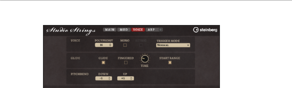
Included Instruments
Studio Strings
205
Voice Page
Polyphony
If Mono mode is deactivated, you can use this parameter to specify how many
notes can be played simultaneously.
Mono
Activates monophonic playback.
Retrigger
This option is only available in Mono mode. If Retrigger is activated, a note that
was stolen by another note is retriggered if you still hold the stolen note when
you release the new one.
This way, you can play trills by holding one note and quickly and repeatedly
pressing and releasing another note, for example.
Trigger Mode
Defines the trigger behavior for new notes.
•Normal triggers a new note when the previous note gets stolen. The
sample and the envelope of the new note are triggered from the start.
To minimize discontinuities, use the Fade Out parameter of the zone.
•Resume does not always trigger a new note.
If the new note stays within the same zone, the envelope is retriggered, but
resumes at the level of the stolen note. The pitch of the zone is set to the
new note.
If the new note plays in a different zone, the sample and the envelope of the
new note are triggered from the start.
•Legato does not always trigger a new note.
If the new note stays within the same zone, the envelope keeps running.
The pitch of the zone is set to the new note.
If the new note plays in a different zone, the sample and the envelope of the
new note are triggered from the start.
•Resume Keeps Zone does not trigger a new note upon note stealing. The
envelope resumes at the level of the stolen note and the pitch of the zone is
set to the new note, even if the new note plays in a different zone.
•Legato Keeps Zone does not trigger a new note upon note stealing. The
envelope keeps running and the pitch of the zone is set to the new note,
even if the new note plays in a different zone.
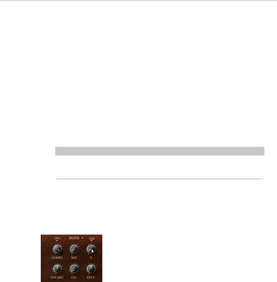
Included Instruments
Studio Strings
206
Glide
Allows you to bend the pitch between notes that follow each other. You achieve
the best results in Mono mode.
Fingered
Activate this parameter to glide the pitch only between notes that are played
legato.
Glide Time
Sets the glide time, that is, the time it takes to bend the pitch from one note to
the next.
Start Range
Activate Start Range to use a shorter sample attack for notes that are played
legato in Mono mode. This allows for a more realistic transition between notes,
especially in combination with the Glide parameter. Use the Attack Time of the
amplifier envelope to shape the effective attack of a note.
NOTE
The Start Range affects only sustained articulations. For staccato, pizzicato, and
crescendo articulations, it has no effect.
Pitchbend Up/Pitchbend Down
Determines the range for the modulation that is applied when you move the
pitchbend wheel.
Filter Section
Filter On/Off
Activates/Deactivates the filter.
Filter Shape
• LP24, 18, 12, and 6 are low-pass filters with 24, 18, 12, and 6 dB/oct.
Frequencies above the cutoff are attenuated.
• BP12 and BP24 are band-pass filters with 12 and 24 dB/oct. Frequencies
below and above the cutoff are attenuated.
• HP6+LP18 and HP6+LP12 are combinations of a high-pass filter with 6 dB/
oct and a low-pass filter with 18 and 12 dB/oct, respectively (asymmetric
band-pass filter). Frequencies below and above the cutoff are attenuated.
Attenuation is more pronounced for the frequencies above the cutoff.

Included Instruments
Studio Strings
207
• HP12+LP6 and HP18+LP6 are combinations of a high-pass filter with 12
and 18 dB/oct and a low-pass filter with 6 dB/oct (asymmetric band-pass
filter). Frequencies below and above the cutoff are attenuated. Attenuation
is more pronounced for the frequencies below the cutoff.
• HP24, 18, 12, and 6 are high-pass filters with 24, 18, 12, and 6 dB/oct.
Frequencies below the cutoff are attenuated.
• BR12 and BR24 are band-reject filters with 12 and 24 dB/oct. Frequencies
around the cutoff are attenuated.
• BR12+LP6 and BR12+LP12 are combinations of a band-reject filter with 12
dB/oct and a low-pass filter with 6 and 12 dB/oct, respectively. Frequencies
around and above the cutoff are attenuated.
• BP12+BR12 is a band-pass filter with 12 dB/oct plus a band-reject filter
with 12 dB/oct. Frequencies below, above, and around the cutoff are
attenuated.
• HP6+BR12 and HP12+BR12 are combinations of a high-pass filter with 6
and 12 dB/oct and a band-reject filter with 12 dB/oct. Frequencies below
and around the cutoff are attenuated.
• AP is an all-pass filter with 18 dB/oct. Frequencies around the cutoff are
attenuated.
• AP+LP6 is an all-pass filter with 18 dB/oct plus a low-pass filter with 6 dB/
oct. Frequencies around and above the cutoff are attenuated.
• HP6+AP is a high-pass filter with 6 dB/oct plus an all-pass filter with 18
dB/oct. Frequencies around and below the cutoff are attenuated.
Cutoff
Controls the cutoff frequency of the filter.
Resonance
Emphasizes the frequencies around the cutoff. At higher settings, the filter self-
oscillates, which results in a ringing tone.
Distortion
Adds distortion to the signal. The following distortion types are available:
•Tube adds warm, tube-like distortion.
•Hard Clip adds bright, transistor-like distortion.
•Bit Reduction adds digital distortion by means of quantization noise.
•Rate Reduction adds digital distortion by means of aliasing.
•Rate Reduction Key Follow adds digital distortion by means of aliasing, but
with Key Follow. The rate reduction follows the keyboard, so the higher you
play, the higher the sample rate.
Envelope Amount
Controls the cutoff modulation from the filter envelope.
Cutoff Velocity
Controls the cutoff modulation from velocity.
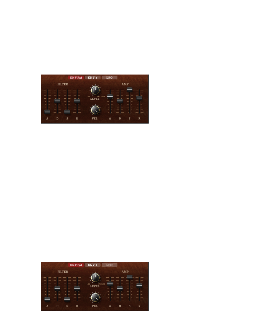
Included Instruments
Studio Strings
208
Cutoff Key Follow
Adjusts the cutoff modulation using the note number. Increase this parameter
to raise the cutoff with higher notes. At 100 %, the cutoff follows the played pitch
exactly.
Filter Envelope
On the left on the Env F/A tab, you can set up the filter envelope.
Attack
Controls the attack time of the filter envelope.
Decay
Controls the decay time of the filter envelope.
Sustain
Controls the sustain level of the filter envelope.
Release
Controls the release time of the filter envelope.
Amplifier and Amplifier Envelope
On the right of the Env F/A tab, you can make settings for the amplifier and the amplifier
envelope.
Amplifier Parameters
Level
Controls the overall volume of the sound.
Velocity
Controls the level modulation from velocity. At 0, all notes are played with the
same level.
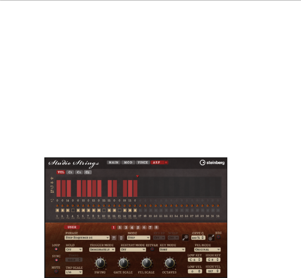
Included Instruments
Studio Strings
209
Amplifier Envelope Parameters
Attack
Controls the attack time of the amplifier envelope.
Decay
Controls the decay time of the amplifier envelope.
Sustain
Controls the sustain level of the amplifier envelope.
Release
Controls the release time of the amplifier envelope.
Arp Page
This page contains the same parameters as the FlexPhraser.
RELATED LINKS
FlexPhraser on page 76
Effects Reference
210
Reverb Effects
REVerence
REVerence is a convolution tool that allows you to apply room characteristics (reverb) to the
audio.
By recording an impulse in a room, you capture the characteristics of this room. Convolution
superimposes these characteristics to the sound. The result is a very natural sounding
reverb. Included with this effect is a collection of high-quality reverb impulse responses.
Impulse Response
Allows you to select an impulse response. This determines the basic sound
character of the reverb.
Reverse
Reverses the impulse response.
Predelay
Determines the amount of time between the dry signal and the onset of the
reverb. With higher predelay values, you can simulate larger rooms.
Time
Controls the reverb time. At a setting of 100 %, the impulse response is applied
with its original length.
Size
Scales the size of the simulated room. At a setting of 100 %, the impulse
response is applied as recorded in the original room.
Effects Reference
Reverb Effects
211
Level
Adjusts the level of the impulse response.
Equalizer
Activates the built-in three-band equalizer.
ER/Tail Split
Sets the split point between the early reflections and the reverb tail.
ER/Tail Mix
Sets the balance between the early reflections and the reverb tail. At a setting of
50 % the early reflections and the tail have the same volume level. Settings below
50 % raise the early reflections and lower the tail, as a result the sound source
moves towards the front of the room. Settings above 50 % raise the tail and lower
the early reflections, as a result the sound source moves towards the back of the
room.
Reverb
This effect produces a high-quality algorithmic reverb with early reflections and reverb tail.
The early reflections are responsible for the spatial impression in the first milliseconds of
the reverb. For emulating different rooms, you can choose between different early reflection
patterns and adjust their size. The reverb tail, or late reverberation, offers parameters for
controlling the room size and the reverb time. You can adjust the reverb time individually in
three frequency bands.
Predelay
Determines how much time passes before the reverb is applied. This allows you
to simulate larger rooms by increasing the time it takes for the first reflections to
reach the listener.
Early Reflections
Here, you select an early reflections pattern. The early reflections pattern
contains the most important delays that deliver the key information for the
spatial impression of the room.
Show Early Reflections Page/Show Chorusing Page
With these two buttons below the Early Reflections pop-up menu, you can choose
whether to display the early reflections settings or the chorusing settings in the
lower left part of the effect panel.

Effects Reference
Reverb Effects
212
ER/Tail
Sets the level balance between the early reflections and the reverb tail. At a
setting of 50 %, early reflections and tail have the same volume. Settings below
50 % raise the early reflections and lower the tail, as a result the sound source
moves towards the front of the room. Settings above 50 % raise the tail and lower
the early reflections, as a result the sound source moves toward the back of the
room.
Delay
Delays the onset of the reverb tail.
Room Size
Controls the dimensions of the simulated room. At a setting of 100 %, the
dimensions correspond to a cathedral or a large concert hall. At a setting of 50 %,
the dimensions correspond to a medium-sized room or studio. Settings below 50
% simulate the dimensions of small rooms or a booth.
Main Time
Controls the overall reverb time of the tail. The higher this value, the longer the
reverb tail will decay. At a setting of 100 %, the reverb time is infinitely long. The
Main Time parameter also represents the mid band of the reverb tail.
High Time
Controls the reverb time for the high frequencies of the reverb tail. With positive
values, the decay time of the high frequencies is longer. With negative values, it is
shorter. Frequencies are affected depending on the High Freq parameter.
Low Time
Controls the reverb time for the low frequencies of the reverb tail. With positive
values, low frequencies decay longer and vice versa. Frequencies will be affected
depending on the Low Freq parameter.
High Freq
Sets the cross-over frequency between the mid and the high band of the reverb
tail. You can offset the reverb time for frequencies above this value from the main
reverb time with the High Time parameter.
Low Freq
Sets the cross-over frequency between the low and the mid band of the reverb
tail. The reverb time for frequencies below this value can be offset from the main
reverb time with the Low Time parameter.
Size
Adjusts the length of the early reflections pattern. At a setting of 100 %, the
pattern is applied with its original length and the room sounds the most natural.
At settings below 100 %, the early reflections pattern is compressed and the
room is perceived smaller.
ER Low Cut
Attenuates the low frequencies of the early reflections. The higher this value, the
fewer low frequencies are present in the early reflections.

Effects Reference
Reverb Effects
213
ER High Cut
Attenuates the high frequencies of the early reflections. The lower this value, the
fewer high frequencies the early reflections will have.
Shape
Controls the attack of the reverb tail. At a setting of 0 %, the attack is more
immediate, which is a good setting for drums. The higher this value, the less
immediate the attack.
Density
Adjusts the echo density of the reverb tail. At a setting of 100 %, single reflections
from walls cannot be heard. The lower this value, the more single reflections can
be heard.
Tail High Cut
Attenuates the high frequencies of the reverb tail. The lower this value, the fewer
high frequencies the reverb tail will have.
Width
Adjusts the output of the reverb signal between mono and stereo. At a setting of 0
%, the output of the reverb is mono, at 100 % it is stereo.
Mix
Sets the ratio between the dry and the wet signal.
Chorusing
Chorusing allows you to enrich the reverb tail through subtle pitch modulations. To access
the chorusing parameters, click the Show Chorusing Page button.
Chorusing On/Off
Activates/Deactivates the chorusing effect.
Chorusing Rate
Specifies the frequency of the pitch modulation.
Chorusing Depth
Sets the intensity of the pitch modulation.
Effects Reference
Delay Effects
214
Delay Effects
Multi Delay
This effect produces delays, with adjustable time, feedback, and filters.
Mode
•Stereo has two independent delay lines, one for the left and one for the
right audio channel, each with a feedback path of its own.
•Cross has two delay lines with cross feedback, where the delay of the left
channel is fed back into the delay of the right channel, and vice versa.
•Ping-Pong mixes the left and right input channels and sends the mixed
signal to hard-panned left and right delays. This way, the echoes bounce
like a ping-pong ball between left and right in the stereo panorama.
Time
Sets the overall time for the left and right delay. Use the Delay L/R parameter to
shorten the time for the left or right delay.
Sync
Activate Sync to synchronize the delay time to the host tempo. If Sync is activated,
the time is set as a note value.
NOTE
The maximum delay time is 5000 ms. If the note length exceeds this value, it is
automatically shortened.
Delay L/R
Offsets the time of the left or right delay from the overall delay time. At a factor of
1, the right or left delay time has the same length as the overall delay time. At a
factor of 0.5, the time is half as long as the overall delay time.
• To offset the left delay time, turn the control to the left.
• To offset the right delay time, turn the control to the right.
Feedback
Sets the overall amount of feedback for the left and right delay. Feedback means
that the output of the delay is fed back to its input. At a setting of 0 %, you hear
one echo. At a setting of 100 %, the echoes repeat endlessly.
Effects Reference
EQ Effects
215
Feedback L/R
Offsets the amount of feedback of the left or right delay from the overall
feedback. A factor of 1 means that the amount of feedback corresponds to
the overall feedback. A factor of 0.5 means that the amount is half the overall
feedback.
• To offset the left feedback, turn the control to the left.
• To offset the right feedback, turn the control to the right.
NOTE
This parameter is only available in Stereo mode.
High Freq
Attenuates the high frequencies of the delays.
Low Freq
Attenuates the low frequencies of the delays.
Mix
Sets the ratio between the dry and the wet signal.
EQ Effects
Studio EQ
Studio EQ is a high-quality 4-band parametric equalizer.
With the four frequency bands, you can shape the tone color, to create a brighter or darker
sound, for example. The two mid-range bands act as peak filters and the low and high bands
act as shelving filters. All bands are fully parametric with adjustable gain, frequency, and Q
factor. Each frequency band offers the following controls:
On/Off
Activates/Deactivates the frequency band.
Gain
Sets the amount of cut or boost for the corresponding band.
Freq
Sets the frequency that is cut or boosted with the Gain parameter.
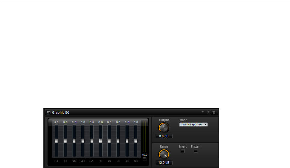
Effects Reference
EQ Effects
216
Q (Quality)
Adjusts the bandwidth of the mid-range peak filters from wide to narrow. By
increasing the Q value on the low and high shelving filters, you can add a dip to
their shape.
• To adjust the parameters Gain and Freq simultaneously, drag the points in the EQ
curve display.
Graphic EQ
Graphic EQ is an equalizer with ten frequency bands that can be cut or boosted by up to 12
dB. In addition, you can specify the overall range and output of the equalizer.
Output
Controls the overall output level of the equalizer.
Mode
Allows you to add color or character to the equalized output. The following
options are available:
•True Response mode uses serial filters with accurate frequency response.
•Classic mode uses parallel filters where the resonance depends on the
amount of gain.
•Constant Q mode uses parallel filters where the resonance is raised when
boosting the gain.
Range
Adjusts the maximum cut or boost for all frequency bands together.
Invert
Activate this to invert the EQ curve.
Flatten
Resets all frequency bands to 0 dB.
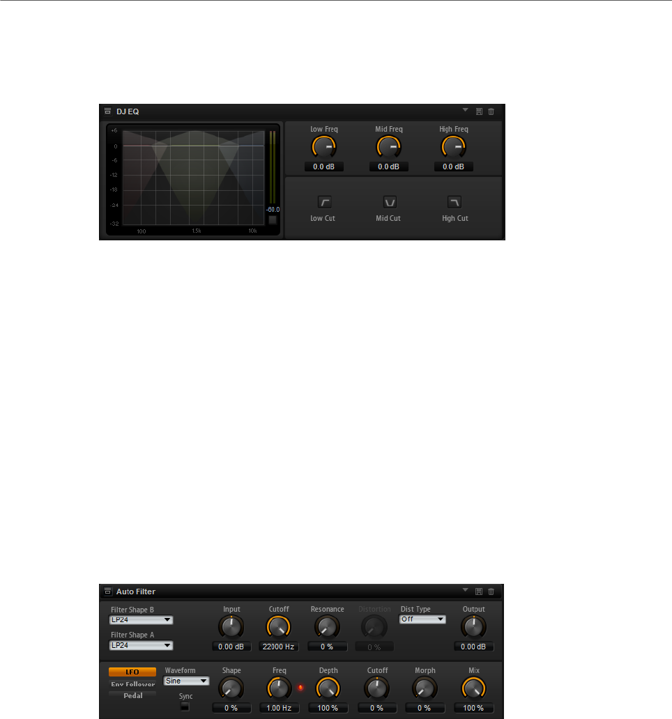
Effects Reference
Filter Effects
217
DJ-EQ
This plug-in is an easy-to-use 3-band parametric equalizer that resembles the EQs found on
typical DJ mixers. This plug-in is designed for quick sound fixes.
Low Freq/Mid Freq/High Freq
Set the amount of boost or attenuation for the low, mid, and high bands.
You can also click and drag in the display to change these values.
Low Cut/Mid Cut/ High Cut
Cut the low, mid, and high bands.
Reset Output Peak Level
Resets the peak level that is displayed in the output meter.
Filter Effects
Auto Filter
Auto Filter provides two morphable filter shapes with distortion.
The morphing between the two shapes, as well as the cutoff, can be controlled with a manual
pedal control, an LFO, or an envelope shaper.
Filter Parameters
Filter Shape
• LP24, 18, 12, and 6 are low-pass filters with 24, 18, 12, and 6 dB/oct.
Frequencies above the cutoff are attenuated.
• BP12 and BP24 are band-pass filters with 12 and 24 dB/oct. Frequencies
below and above the cutoff are attenuated.
• HP6+LP18 and HP6+LP12 are combinations of a high-pass filter with 6 dB/
oct and a low-pass filter with 18 and 12 dB/oct, respectively (asymmetric

Effects Reference
Filter Effects
218
band-pass filter). Frequencies below and above the cutoff are attenuated.
Attenuation is more pronounced for the frequencies above the cutoff.
• HP12+LP6 and HP18+LP6 are combinations of a high-pass filter with 12
and 18 dB/oct and a low-pass filter with 6 dB/oct (asymmetric band-pass
filter). Frequencies below and above the cutoff are attenuated. Attenuation
is more pronounced for the frequencies below the cutoff.
• HP24, 18, 12, and 6 are high-pass filters with 24, 18, 12, and 6 dB/oct.
Frequencies below the cutoff are attenuated.
• BR12 and BR24 are band-reject filters with 12 and 24 dB/oct. Frequencies
around the cutoff are attenuated.
• BR12+LP6 and BR12+LP12 are combinations of a band-reject filter with 12
dB/oct and a low-pass filter with 6 and 12 dB/oct, respectively. Frequencies
around and above the cutoff are attenuated.
• BP12+BR12 is a band-pass filter with 12 dB/oct plus a band-reject filter
with 12 dB/oct. Frequencies below, above, and around the cutoff are
attenuated.
• HP6+BR12 and HP12+BR12 are combinations of a high-pass filter with 6
and 12 dB/oct and a band-reject filter with 12 dB/oct. Frequencies below
and around the cutoff are attenuated.
• AP is an all-pass filter with 18 dB/oct. Frequencies around the cutoff are
attenuated.
• AP+LP6 is an all-pass filter with 18 dB/oct plus a low-pass filter with 6 dB/
oct. Frequencies around and above the cutoff are attenuated.
• HP6+AP is a high-pass filter with 6 dB/oct plus an all-pass filter with 18
dB/oct. Frequencies around and below the cutoff are attenuated.
Input
Adjusts the gain before the filter and distortion. This parameter only affects the
wet signal.
Cutoff
Specifies the cutoff frequency of the filter.
Resonance
Emphasizes the frequencies around the cutoff. At higher resonance settings, the
filter self-oscillates, which results in a ringing tone.
Distortion Type
The following options are available:
• When this parameter is set to Off, the filter offers no distortion.
•Tube Drive offers a lot of character by adding warm, tube-like distortion.
•Hard Clip adds bright, transistor-like distortion.
•Bit Red adds digital distortion by means of quantization noise.
•Rate Red adds digital distortion by means of aliasing.

Effects Reference
Filter Effects
219
Distortion
Adds distortion to the signal. The effect depends on the selected distortion type.
At higher settings, it creates a very intense distortion effect.
NOTE
This parameter is not available if Distortion Type is set to Off.
Output
Adjusts the gain after the filter and distortion. This parameter only affects the wet
signal.
Mix
Sets the ratio between the dry and the wet signal.
LFO Section
LFO Waveform and Shape
Waveform selects the basic type of waveform. Shape changes the characteristic
of the waveform.
•Sine produces smooth modulation. Shape adds additional harmonics to the
waveform.
•Triangle is similar in character to Sine. The waveform periodically ramps
up and down. Shape continuously changes the triangle waveform to a
trapezoid.
•Saw produces a ramp cycle. Shape continuously changes the waveform
from ramp down to triangle to ramp up.
•Pulse produces stepped modulation, where the modulation switches
abruptly between two values. Shape continuously changes the ratio
between the high and low state of the waveform. At 50 %, it produces a
square wave.
•Ramp is similar to the Saw waveform. Shape increasingly puts silence
before the sawtooth ramps up.
•Log is a logarithmic curvature. Shape continuously changes the curvature
from negative to positive.
•S & H 1 produces random stepped modulation, where each step is
different. Shape puts ramps between the steps and produces a smooth
random signal when fully turned right.
•S & H 2 is similar to S & H 1. The steps alternate between random high and
low values. Shape puts ramps between the steps and produces a smooth
random signal when fully turned right.
Freq
Determines the frequency of the cutoff modulation.
Sync
Activate this to set the Freq parameter in fractions of beats.

Effects Reference
Filter Effects
220
Depth
Determines the output level of the LFO modulation signal.
Cutoff
Determines the modulation intensity of the LFO on the filter cutoff.
Morph
Determines the modulation intensity of the LFO on the filter morph.
Envelope Follower Section
The Envelope Follower traces the input signal with an adjustable attack and release time and
delivers a modulation signal representing the level envelope of the signal.
Sensitivity
All input signals are mixed down to mono before they are sent to the Envelope
Follower. This parameter sets the optimum input level for the Envelope Follower.
Attack
Adjusts the attack time, that is, the time the Envelope Follower needs to
approach increasing input levels.
Release
Adjusts the release time, that is, the time the Envelope Follower needs to
approach decreasing input levels.
Depth
Determines the output level of the modulation signal of the Envelope Follower.
Cutoff
Determines the modulation intensity of the Envelope Follower on the filter cutoff.
Morph
Determines the modulation intensity of the Envelope Follower on the filter
morph.
Pedal Section
Pedal
Sets the position of the pedal.
Depth
Determines the output level of the pedal modulation signal.
Cutoff
Determines the modulation intensity of the pedal on the filter cutoff.
Morph
Determines the modulation intensity of the pedal on the filter morph.
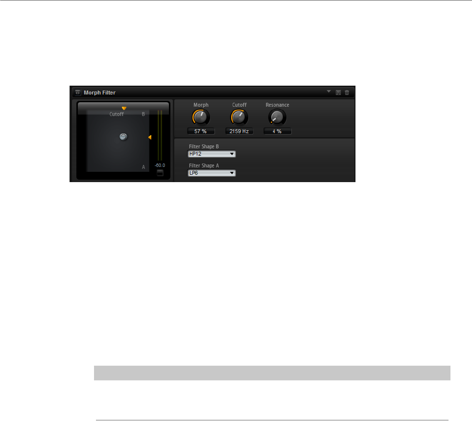
Effects Reference
Filter Effects
221
Morph Filter
Morph Filter allows you to mix low-pass and high-pass filter effects, allowing for creative
morphings between two filters. You can specify the filter shapes independently for filter
shape A and B.
Filter Shape B
Here, you can choose between several high-pass and band-rejection filter
shapes.
Filter Shape A
Here, you can select a low-pass or a band-pass filter shape.
Morph
Allows you to mix the output between the two selected filters.
Cutoff
Adjusts the cutoff frequency of the filters.
NOTE
You can also set the Cutoff and Morph parameters simultaneously by clicking in
the display and dragging.
Resonance
Emphasizes the frequencies around the cutoff frequency. For an electronic
sound, increase the resonance. At higher resonance settings, the filter self-
oscillates, which results in a ringing tone.
Resonator
The sound of the human voice or of acoustic instruments can be characterized by their
distinctive formant regions, that is, by resonances in the frequency spectrum that are typical
for a particular sound.
For example, the vowel “ah” (as in father) sung by a male singer has three characteristic
formants: F1 = 570 Hz, F2 = 840 Hz, and F3 = 2410 Hz. The Resonator effect allows you to
induce such formant regions to a sound by using three filters that are connected in parallel.
You can specify the positions and levels of the formant regions by adjusting the Cutoff,
Resonance, and Gain parameters of the filters.
The Resonator effect comes with 14 predefined filter shapes that determine the basic sound
character. In addition, three LFOs can be used to modulate each filter separately, which
allows for adding extra motion to the sound.

Effects Reference
Filter Effects
222
Resonator Shape
Defines the basic sound character of the effect. Each shape is a unique
combination of different filter types for the low, mid, and high frequency bands.
Option Filter Low/Mid/High
Low-Pass 1 LP6/LP6/LP6
Low-Pass 2 LP12/LP12/LP12
Band-Pass 1 BP12/(-1)BP12/BP12*
Band-Pass 2 BP12/BP12/BP12
High-Pass 1 HP6/HP6/HP6
High-Pass 2 HP12/HP12/HP12
Peak 1 LP6/(-1)BP12/HP6*
Peak 2 LP6/BP12/HP6
Bat 1 HP12/BP12/LP12
Bat 2 HP6/BP12/LP6
Wings 1 LP6/BR12/HP6
Wings 2 HP12/BR12/LP12
Wings 3 LP6/(-1)BR12/HP6*
Wings 4 HP12/(-1)BR12/LP12*
*(-1) means that the phase is inverted
Mix
Sets the ratio between the dry and the wet signal.
Cutoff Spread
Spreads the cutoff frequencies between the channels of the effect.
For example, if the effect is used in stereo, positive Cutoff Spread values shift the
cutoff down on the left channel and up on the right channel.
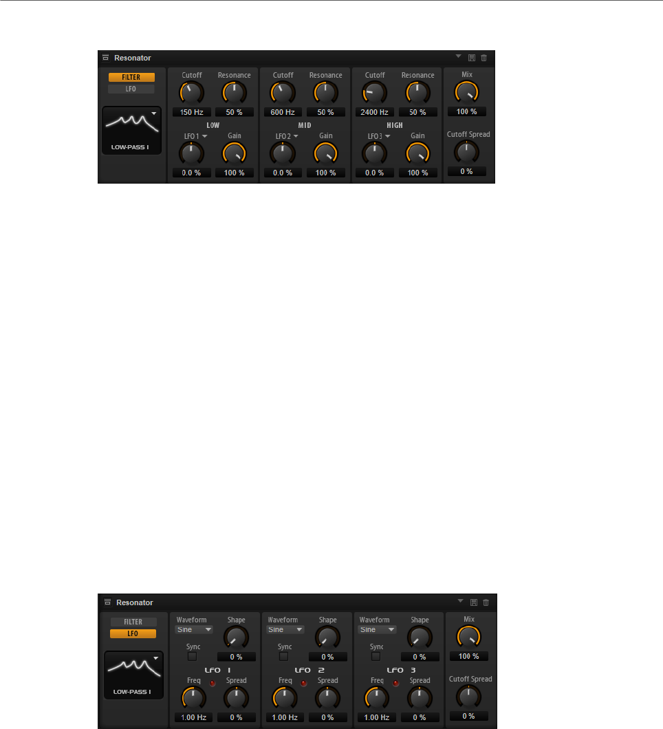
Effects Reference
Filter Effects
223
Filter Tab
Cutoff
Adjusts the cutoff frequency of the filter, that is, the center frequency of the
formant region.
Resonance
Adjusts the resonance of the filter. The resonance determines how much the
formant region is emphasized. At higher settings, the filter self-oscillates, which
results in a ringing tone.
Gain
Adjusts the input gain of the filter. The gain determines the level of the formant
region.
LFO Modulation Source
Allows you to select the LFO that modulates the cutoff.
LFO Modulation Depth
Adjusts the cutoff modulation from the LFO.
LFO Tab
LFO Waveform and Shape
•Sine produces smooth modulation, suitable for vibrato or tremolo. Shape
adds additional harmonics to the waveform.
•Triangle is similar to Sine. Shape continuously changes the triangle
waveform to a trapezoid.
•Saw produces a ramp cycle. Shape continuously changes the waveform
from ramp down to triangle to ramp up.
•Pulse produces stepped modulation, where the modulation switches
abruptly between two values. Shape continuously changes the ratio
Effects Reference
Filter Effects
224
between the high and low state of the waveform. If Shape is set to 50 %, a
square wave is produced.
•Ramp is similar to the Saw waveform. Shape increasingly puts silence
before the sawtooth ramp up begins.
•Log produces a logarithmic modulation. Shape continuously changes the
logarithmic curvature from negative to positive.
•S & H 1 produces randomly stepped modulation, where each step is
different. Shape puts ramps between the steps and changes the S & H into
a smooth random signal when fully turned right.
•S & H 2 is similar to S & H 1. The steps alternate between random high and
low values. Shape puts ramps between the steps and changes the S & H
into a smooth random signal when fully turned right.
Spread
For each channel of the effect, there is a separate LFO signal. This parameter
spreads the phase of the LFO signals across the different channels.
For example, if the effect is used in stereo, positive values shift the LFO phase
forward on the left channel and backward on the right channel.
Sync
Activate this to set the Freq parameter in fractions of beats.
Freq
Determines the frequency of the cutoff modulation.
WahWah
WahWah is a variable slope band-pass filter modeling the well-known analog pedal effect.
You can independently specify the frequency, width, and the gain for the low and high pedal
positions. The crossover point between the low and high pedal positions lies at 50.
Pedal
Controls the filter frequency sweep.
Freq Low/Freq High
These parameters determine the frequency of the filter for the low and high
pedal positions.
Width Low/Width High
These parameters determine the width (resonance) of the filter for the low and
high pedal positions.
Effects Reference
Distortion Effects
225
Gain Low/Gain High
These parameters determine the gain of the filter for the low and high pedal
positions.
Slope
Here, you can choose between two filter slope values: 6 dB or 12 dB.
Distortion Effects
Amplifier
This effect emulates the sound of an amplifier with speakers.
There are different amplifiers and speaker models you can combine.
Amp Model
Determines the type of amplifier. The sound character of the overdrive changes
with the amplifier. To bypass the amplifier, select No Amp.
Speaker Model
Determines the speaker model type. Each model colors the sound uniquely. To
bypass the model, select No Speaker.
Drive
Adjusts the amount of overdrive.
Bass
Adjusts the tone color of the low frequencies.
Middle
Adjusts the tone color of the mid frequencies.
Treble
Adjusts the tone color of the high frequencies.
Presence
Adds brightness to the sound.
Low Damp
Attenuates the low frequencies of the speakers.
Effects Reference
Distortion Effects
226
High Damp
Attenuates the high frequencies of the speakers.
Channel Mode
Defines which output channels of the amplifier deliver a distorted signal. You can
set it to L (Left), R (Right) or L/R (Both). When set to L or R, the other channel
provides a clean signal.
Output
Controls the output level of the amplifier.
Distortion
This effect offers the whole range of distortion, from low fidelity, digital distortion to high
fidelity, analog sounding distortion. The available distortion types (Rate Red, Tube Drive,
Hard Clip, and Bit Red) can be freely combined.
In Gain
Adjusts the input level of the sound.
Rate Red (Rate Reduction)
Rate reduction distorts the sound by means of aliasing. Enable the Rate Red
option to activate the control that adjusts the amount of aliasing. The lower the
setting, the more aliasing is added.
Tube Drive
Adds warm, tube-like distortion to the sound. Enable the Tube Drive option to
activate the control that adjusts the amount of distortion. The higher the setting,
the more distortion is added.
Hard Clip
Adds bright, transistor-like distortion to the sound. Enable the Hard Clip option to
activate the control that adjusts the amount of distortion. The higher the setting,
the more distortion is added.
Bit Red (Bit Reduction)
Bit reduction distorts the sound by means of quantization noise. Enable the Bit
Red option to activate the control that adjusts the amount of quantization noise.
The lower the setting, the more quantization noise is added.
Out Gain
Adjusts the output level of the sound.
Mix
Sets the ratio between the dry and the wet signal.
Effects Reference
Distortion Effects
227
VST Amp
This effect emulates the sound of an amplifier with speakers. There are different amplifiers
and speaker models you can combine.
Amp Model
Specifies the amplifier type. The sound character of the overdrive changes with
the amplifier. To bypass the amp modeling, select No Amplifier.
Speaker Model
Specifies the speaker model type. Each model colors the sound uniquely. To
bypass the speaker modeling, select No Cabinet.
Drive
Adjusts the amount of overdrive.
Bass
Adjusts the tone color of the low frequencies.
Middle
Adjusts the tone color of the mid frequencies.
Treble
Adjusts the tone color of the high frequencies.
Presence
Adjusts the brightness of the sound.
Mic Type
You can choose between two microphone types. If this control is set to 0 %, a
large-diaphragm condenser microphone is used. At 100 %, you get a dynamic
microphone. Settings in between allow you to fade between the characteristics of
these two microphones.
Microphone Position
Here, you can choose between seven positions to place the microphone. These
positions result from two different angles (center and edge) and three different
distances from the speaker, as well as an additional center position at an even
greater distance from the speaker.
Channel Mode
Determines in which way the two input channels are distorted.
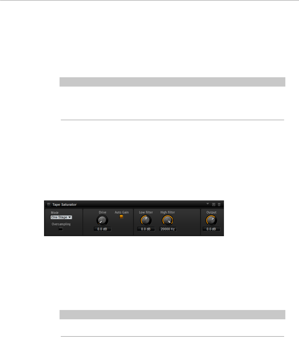
Effects Reference
Distortion Effects
228
•L (Left) only distorts the left input channel. The right channel remains
clean and unprocessed.
•R (Right) only distorts the right input channel. The left channel remains
clean and unprocessed.
•L+R (Left + Right) sums the two input channels into a mono signal which is
then distorted.
•Stereo distorts the two input channels independently.
NOTE
The L and R modes allow you to cascade two VST Amp effects, that is, to use the
first one to processes the left channel and the second one to process the right
channel at different settings.
Output
Controls the output level of the amplifier.
Tape Saturator
Tape Saturator simulates the behavior of classic tape recorders. These machines produced a
specific saturation when recording higher input levels, which led to a compressed signal with
light distortion.
Mode
Here, you can choose between the effect of a single (One Stage) or two cascaded
tape machines (Two Stage). Two Stage mode leads to higher saturation and
compression.
Oversampling
Activate this parameter to increase the accuracy of the effect by oversampling.
NOTE
If this parameter is activated, the effect requires more processing power.
Drive
Determines the level of the input signal and thus the amount of saturation.
Auto Gain
Activate this option for an automatic level compensation.
Low Filter
Here, you can adjust the low frequency range below 1000 Hz by +/- 3 dB.
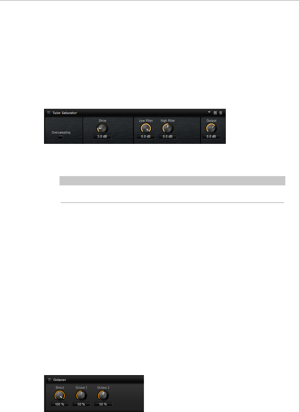
Effects Reference
Pitch Shift Effects
229
High Filter
Here, you can attenuate the high frequency range. This high-cut filter works with
a slope of 24 dB/octave.
Output
Determines the level of the output signal.
Tube Saturator
This effect enriches the sound by adding the characteristic harmonics of a saturated tube to
the audio signal.
Oversampling
Increases the accuracy of the effect by oversampling.
NOTE
If this parameter is activated, the effect requires more processing power.
Drive
Determines the level of the input signal and thus the amount of saturation.
Low Filter
Allows you to reduce the low frequency range by up to 6 dB before saturation.
High Filter
Allows you to adjust the high frequency range by -/+ 6 dB before saturation.
Output
Determines the level of the output signal.
Pitch Shift Effects
Octaver
Octaver allows you to create two additional voices that follow the original voice an octave
below and above. This effect is best suited for monophonic signals.
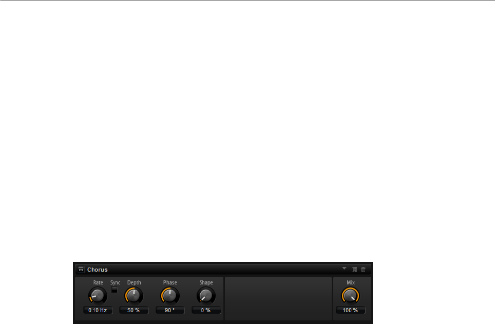
Effects Reference
Modulation Effects
230
Direct
Determines the level of the input signal.
Octave 1
Determines the level of the signal that is produced an octave below the original
voice.
Octave 2
Determines the level of the signal that is produced an octave above the original
voice.
Modulation Effects
Chorus
Chorus thickens and broadens the sound by means of pitch modulation.
Rate
Determines the frequency of the pitch modulation, in Hertz.
Sync
Activate this to set the Rate value in fractions of beats.
Depth
Sets the intensity of the pitch modulation.
Phase
Widens the sound image of the effect from mono to stereo.
Shape
Adjusts the characteristics of the modulation. At a setting of 0 %, the pitch
changes continuously, producing a steady modulation. At a setting of 100 %, the
pitch does not change all the time, producing a less steady modulation.
Mix
Sets the ratio between the dry and the wet signal.
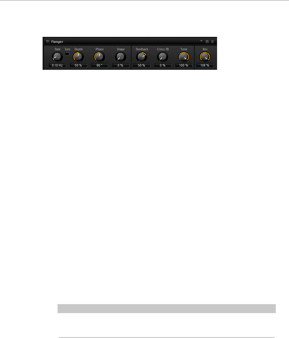
Effects Reference
Modulation Effects
231
Flanger
This effect thickens and broadens the sound by means of pitch modulation.
Rate
Allows you to specify the frequency of the pitch modulation in Hertz.
Sync
Activate this to set the Rate value in fractions of beats.
Depth
Sets the intensity of the pitch modulation.
Phase
Widens the sound image of the effect from mono to stereo. This parameter also
changes the characteristic of the Cross FB parameter.
Shape
Adjusts the characteristics of the modulation. You hear this best when Feedback
is activated. At a setting of 0 %, the sound sweeps linearly up and down. At a
setting of 100 %, the sound sweeps exponentially up and down.
Mix
Sets the ratio between the dry and the wet signal.
Feedback
Adds resonances to the effect. This allows for jet-like sweeps of the sound.
Cross FB
Mixes the feedback of the left channel with the right channel, and vice versa. The
effect of this parameter is influenced by the Phase parameter.
NOTE
This parameter only takes effect if the Feedback parameter is set to a value
above 0 %.
Tone
Adjusts the tone color of the feedback. At lower values, the feedback is less
bright.
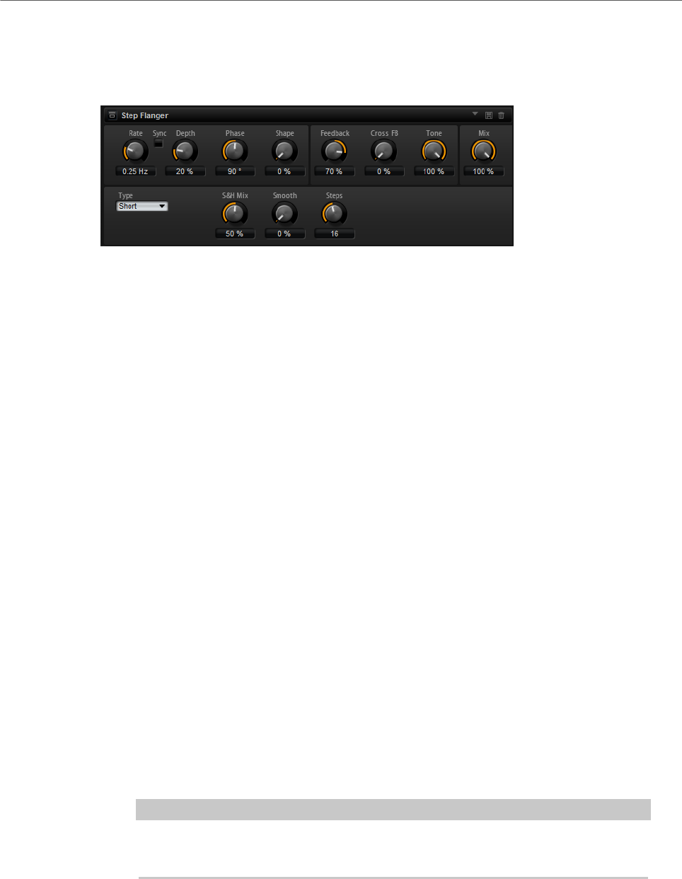
Effects Reference
Modulation Effects
232
Step Flanger
The Step Flanger expands the Flanger with a Sample and Hold section that divides the
modulation signal into a definable number of steps.
Rate
Allows you to specify the frequency of the pitch modulation in Hertz.
Sync
Activate this to set the Rate value in fractions of beats.
Depth
Sets the intensity of the pitch modulation.
Phase
Widens the sound image of the effect from mono to stereo. This parameter also
changes the characteristic of the Cross FB parameter.
Shape
Adjusts the characteristics of the modulation. You hear this best when Feedback
is activated. At a setting of 0 %, the sound sweeps linearly up and down. At a
setting of 100 %, the sound sweeps exponentially up and down.
Mix
Sets the ratio between the dry and the wet signal.
Feedback
Adds resonances to the effect. This allows for jet-like sweeps of the sound.
Cross FB
Mixes the feedback of the left channel with the right channel, and vice versa. The
effect of this parameter is influenced by the Phase parameter.
NOTE
This parameter only takes effect if the Feedback parameter is set to a value
above 0 %.
Tone
Adjusts the tone color of the feedback. At lower values, the feedback is less
bright.
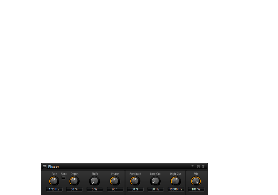
Effects Reference
Modulation Effects
233
Type
Defines the length of the delay line that is modulated. Short produces a sharper
and Long a less defined, more blurred flanger sound.
S&H Mix
Use this parameter to blend the normal modulation signal with the stepped
modulation signal. At 100 %, only the stepped modulation is used.
Smooth
Use this parameter to create ramps between the steps. This way, the stepped
modulation signal sounds smoother.
Steps
Determines into how many steps the modulation signal is divided. You can use up
to 32 steps.
Phaser
The Phaser effect thickens and broadens the sound by means of phase modulation.
Rate
Specifies the frequency of the phase modulation.
Sync
Activate this to set the Rate value in fractions of beats.
Depth
Sets the intensity of the phase modulation.
Shift
Shifts the phase modulation upwards to higher frequencies of the spectrum.
Phase
Widens the sound image of the effect from mono to stereo.
Feedback
Adds resonances to the effect. Higher settings produce a more pronounced
effect.
Low Cut
Attenuates the low frequencies.
High Cut
Attenuates the high frequencies.
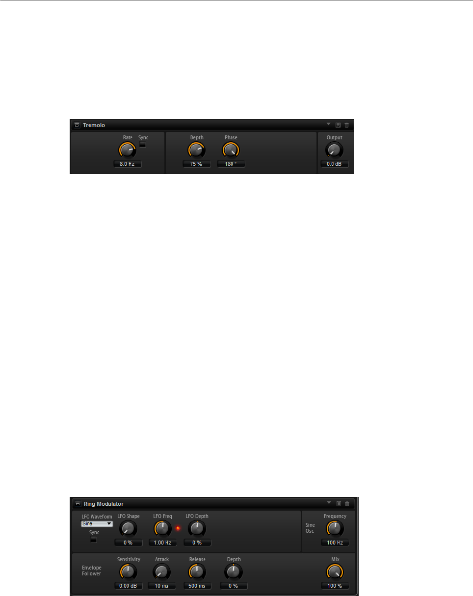
Effects Reference
Modulation Effects
234
Mix
Sets the ratio between the dry and the wet signal.
Tremolo
This effect produces amplitude modulation, that is, cyclic modulation of the level of the
sound.
Rate
Determines the frequency of the amplitude modulation.
Sync
Activate this to set the Rate value in fractions of beats.
Depth
Sets the intensity of the amplitude modulation.
Phase
Widens the sound image of the effect from mono to stereo.
Output
Sets the output level of the effect.
Ring Modulator
The Ring Modulator provides a sine oscillator that is multiplied with the input signal. This
creates metallic, or bell-like, frequencies.
The integrated LFO modulates the frequency of the sine oscillator to vary the created
frequencies over time. In addition, an envelope follower is available, which can be used to
modulate the frequency of the sine oscillator depending on the level of the input signal.
LFO Waveform and Shape
Waveform selects the basic type of waveform. Shape changes the characteristic
of the waveform.
•Sine produces smooth modulation. Shape adds additional harmonics to the
waveform.

Effects Reference
Modulation Effects
235
•Triangle is similar in character to Sine. The waveform periodically ramps
up and down. Shape continuously changes the triangle waveform to a
trapezoid.
•Saw produces a ramp cycle. Shape continuously changes the waveform
from ramp down to triangle to ramp up.
•Pulse produces stepped modulation, where the modulation switches
abruptly between two values. Shape continuously changes the ratio
between the high and low state of the waveform. At 50 %, it produces a
square wave.
•Ramp is similar to the Saw waveform. Shape increasingly puts silence
before the sawtooth ramps up.
•Log is a logarithmic curvature. Shape continuously changes the curvature
from negative to positive.
•S & H 1 produces random stepped modulation, where each step is
different. Shape puts ramps between the steps and produces a smooth
random signal when fully turned right.
•S & H 2 is similar to S & H 1. The steps alternate between random high and
low values. Shape puts ramps between the steps and produces a smooth
random signal when fully turned right.
LFO Freq
Use this to specify the frequency of the LFO for modulating the frequency of the
sine oscillator.
Sync
Activate this to set the LFO Freq value in fractions of beats.
LFO Depth
Sets the intensity of the LFO modulation of the sine oscillator frequency.
Frequency
Determines the frequency of the sine oscillator.
Mix
Sets the ratio between the dry and the wet signal.
Envelope Follower
The Envelope Follower traces the input signal with an adjustable attack and
release time and delivers a modulation signal representing the level envelope of
the signal.
Sensitivity
All input signals are mixed down to mono before they are sent to the Envelope
Follower. The Sensitivity parameter sets the optimum input level for the
Envelope Follower.
Attack
This adjusts the attack time, that is, the time the Envelope Follower needs to
approach increasing input levels.
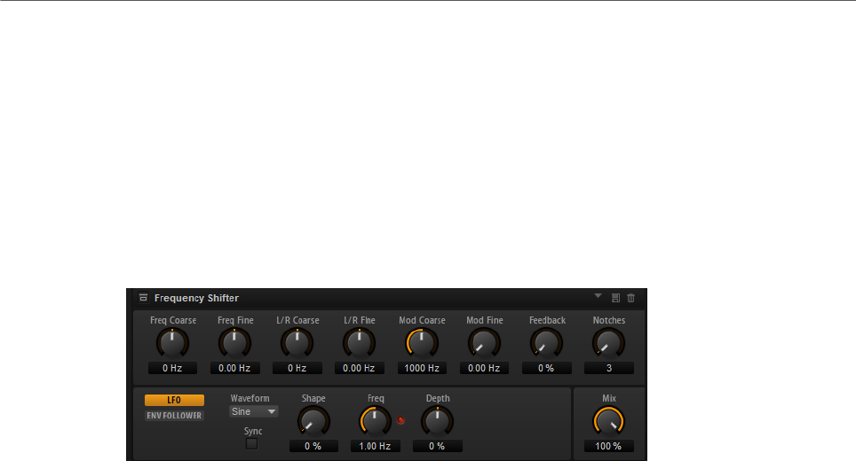
Effects Reference
Modulation Effects
236
Release
This adjusts the release time, that is, the time the Envelope Follower needs to
approach decreasing input levels.
Depth
Determines the output level of the modulation signal of the Envelope Follower.
Frequency Shifter
A frequency shifter shifts each frequency of the input signal by a fixed amount.
Unlike pitch shifters, where the frequencies are shifted by a factor, and where the harmonic
relations are kept, a frequency shifter alters the harmonic relations. Therefore, a larger
frequency shift usually results in a disharmonic sound.
Furthermore, a frequency shifter alters the frequencies by adding an offset, while a pitch
shifter multiplies the frequencies by a factor. The frequency shifter alters lower frequencies
more than higher frequencies.
For example, if the input signal has the frequencies 100 Hz, 1000 Hz, and 10000 Hz, and you
shift the frequency by +100 Hz, the resulting frequencies are 200 Hz, 1100 Hz, and 10100 Hz.
Freq Coarse
Here you set the amount of frequency shift.
Freq Fine
Here you can fine adjust the amount of frequency shift.
L/R Offset Coarse
Sets an offset for the left and right channels. Positive values shift the right
channel upwards and the left channel downwards, and vice versa.
L/R Offset Fine
Allows for fine-adjustments of the offset between the left and right channels.
Positive values shift the right channel upwards and the left channel downwards,
and vice versa.
Mod Coarse
Sets the maximum amount of frequency shift via modulation from LFO and
Envelope Follower.
Mod Fine
Allows for fine-adjustments to the amount of frequency shift via modulation from
LFO and Envelope Follower.

Effects Reference
Modulation Effects
237
Feedback
Sets the amount of feedback, that is, the amount of signal that is sent from the
output of the effect back to its input. The sound is similar to that of a phaser.
You can control the direction and speed of this effect with the Frequency Fine
parameter.
Notches
Here you set the number of notches the phaser effect produces when you use
larger amounts of Feedback.
LFO Section
LFO Waveform and Shape
Waveform selects the basic type of waveform. Shape changes the characteristic
of the waveform.
•Sine produces smooth modulation. Shape adds additional harmonics to the
waveform.
•Triangle is similar in character to Sine. The waveform periodically ramps
up and down. Shape continuously changes the triangle waveform to a
trapezoid.
•Saw produces a ramp cycle. Shape continuously changes the waveform
from ramp down to triangle to ramp up.
•Pulse produces stepped modulation, where the modulation switches
abruptly between two values. Shape continuously changes the ratio
between the high and low state of the waveform. At 50 %, it produces a
square wave.
•Ramp is similar to the Saw waveform. Shape increasingly puts silence
before the sawtooth ramps up.
•Log is a logarithmic curvature. Shape continuously changes the curvature
from negative to positive.
•S & H 1 produces random stepped modulation, where each step is
different. Shape puts ramps between the steps and produces a smooth
random signal when fully turned right.
•S & H 2 is similar to S & H 1. The steps alternate between random high and
low values. Shape puts ramps between the steps and produces a smooth
random signal when fully turned right.
Freq
Specifies the frequency of the LFO in Hertz.
Sync
Activate this to set the Freq parameter in fractions of beats.
Depth
Determines the direction and amount of frequency shift from the LFO modulation
signal.
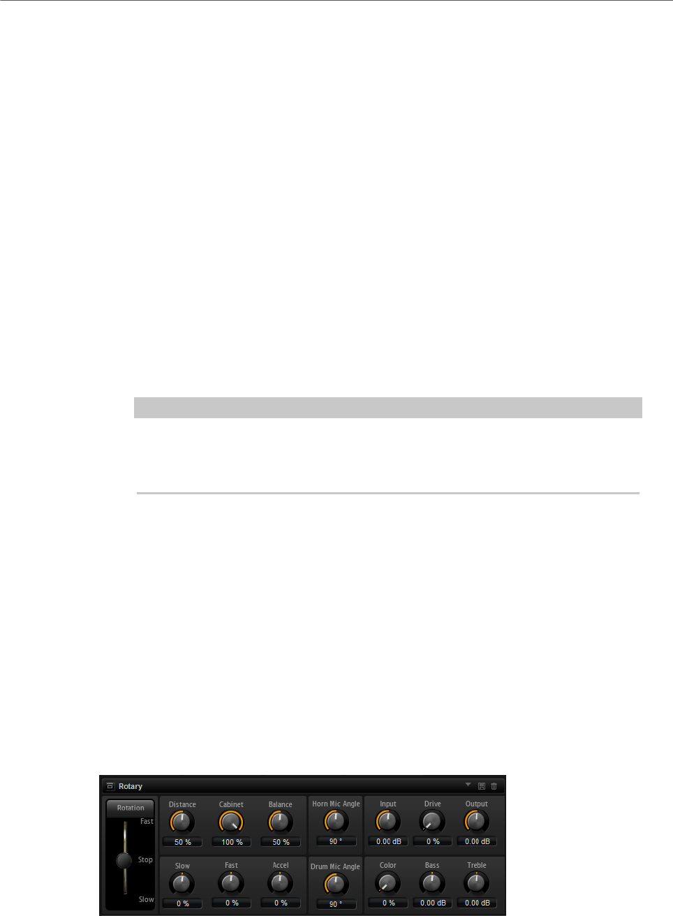
Effects Reference
Modulation Effects
238
Envelope Follower
The Envelope Follower traces the input signal with an adjustable attack and release time and
delivers a modulation signal representing the level envelope of the signal.
Sensitivity
All input signals are mixed down to mono before they are sent to the Envelope
Follower. This parameter sets the optimum input level for the Envelope Follower.
Attack
Adjusts the attack time, that is, the time the Envelope Follower needs to
approach increasing input levels.
Release
Adjusts the release time, that is, the time the Envelope Follower needs to
approach decreasing input levels.
Depth
Determines the direction and amount of frequency shift from the envelope
follower modulation signal.
NOTE
The maximum frequency shift via modulation from LFO or the Envelope Follower
is determined by the parameters Modulation Range Coarse and Modulation
Range Fine.
Mix
Sets the ratio between the dry and the wet signal.
Rotary
The Rotary effect emulates the sound of a vintage rotary speaker including amplifier, horn,
drum, and cabinet.
By emitting the sound via a rotating horn and drum, the rotary speaker produces a Doppler
effect that thickens the sound. The horn and drum rotate at variable speed producing
different amounts of Doppler effect. The amplifier of the rotary speaker adds a warm
sounding distortion, and the horn, drum, and cabinet color the sound uniquely. The horn and
drum are recorded via (virtual) microphones that can be set to different angles to broaden
the sound image. Typically, rotary speakers are used with electric organs.

Effects Reference
Modulation Effects
239
Rotation
This parameter changes the rotation speed of the horn and drum. When set to
Fast, the Doppler effect is stronger. When set to Stop, there is no Doppler effect
because the drum and horn do not rotate. Because the horn and drum accelerate
and decelerate at different speeds, the transition from Slow to Fast and vice
versa sounds the most interesting.
Distance
Sets the distance between the microphones and the horn and drum. The
amplitude modulation of the sound decreases with the distance of the
microphones. Set this to higher values for less amplitude modulation.
Cabinet
The horn and drum sound different when recorded through the louvers of the
cabinet. Use this to color the horn and drum with the sound of the cabinet. At a
setting of 100 %, you get the full sound of the cabinet.
Balance
Here you adjust the balance between the horn and drum microphones. At a
setting of 0 %, you hear only the drum. At a setting of 100 %, you hear only the
horn.
Slow
Adjusts the slow speed of the horn and drum together.
Fast
Adjusts the fast speed of the horn and drum together.
Accel
Adjusts the acceleration time for raising and lowering the rotation speed of the
horn and drum.
Horn Mic Angle
This adjusts the stereo spread of the horn microphones. At a setting of 0°, the
sound image is monophonic. At a setting of 180°, the sound image is fully stereo.
Drum Mic Angle
This adjusts the stereo spread of the drum microphones. At a setting of 0°, the
sound image is monophonic. At a setting of 180°, the sound image is fully stereo.
Input
Adjusts the gain before the rotary and drive.
Drive
Adjusts the distortion of the amplifier.
Output
Adjusts the gain after the rotary and drive.
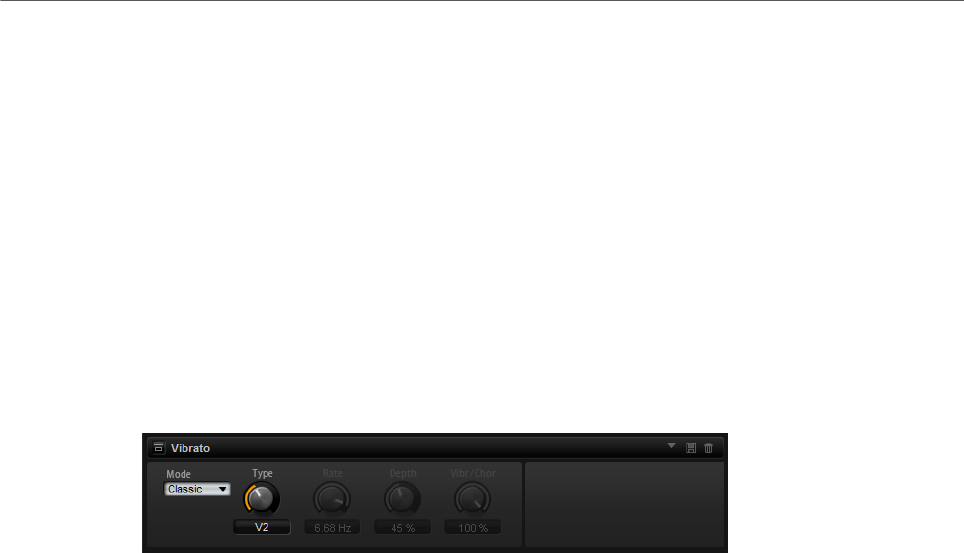
Effects Reference
Modulation Effects
240
Color
Alters the sound of the Rotary effect by changing the timbre, which leads to the
rotation of the horn and the drum being perceived with greater depth.
Bass
Adjusts the tone color of the low frequencies.
Treble
Adjusts the tone color of the high frequencies.
Vibrato
The Vibrato effect emulates the chorus and vibrato effects of vintage organs. It thickens the
sound by means of pitch modulation.
The effect provides direct access to the classic chorus and vibrato settings (C1, C2 and C3
and V1, V2 and V3). In addition, there is a custom mode that allows you to adjust the amount
of chorus or vibrato freely.
Type
Here, you can select the classic chorus and vibrato settings. This control is only
available if the effect is set to Classic mode.
Custom Mode
Activate this to adjust the chorus and vibrato settings freely with the Rate, Depth,
and Vibr/Chor controls.
Rate
Sets the frequency of the pitch modulation.
Depth
Sets the intensity of the pitch modulation.
Vibr/Chor
Controls the mix between the vibrato and the chorus signal. At 100 %, you only
hear the chorus effect.
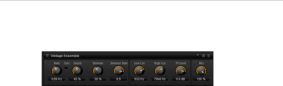
Effects Reference
Dynamics Effects
241
Vintage Ensemble
This effect emulates the sound of classic ensemble modulation effects. It is based on a
delay with LFO-modulated delay times. A secondary LFO with higher frequencies is used to
produce the so-called shimmer.
Rate
Sets the frequency of the LFO.
Sync
If Sync is activated, you can set the Rate value in fractions of beats.
Depth
Sets the intensity of the delay time modulation by the LFO.
Shimmer
Sets the intensity of a secondary faster delay time modulation.
Shimmer Rate
Determines the relation between the speed of the primary and the secondary
delay modulation. For example, with a value of 10, the secondary modulation is
10 times faster.
Low Cut
Applies a low-cut filter to the signal. Only frequencies above the set frequency
are sent to the effect.
High Cut
Applies a high-cut filter to the signal. Only frequencies below the set frequency
are sent to the effect.
FX Level
Allows you to adapt the effect signal level to compensate for level reductions
caused by the low-cut and high-cut filters.
Mix
Sets the ratio between the dry and the wet signal.
Dynamics Effects
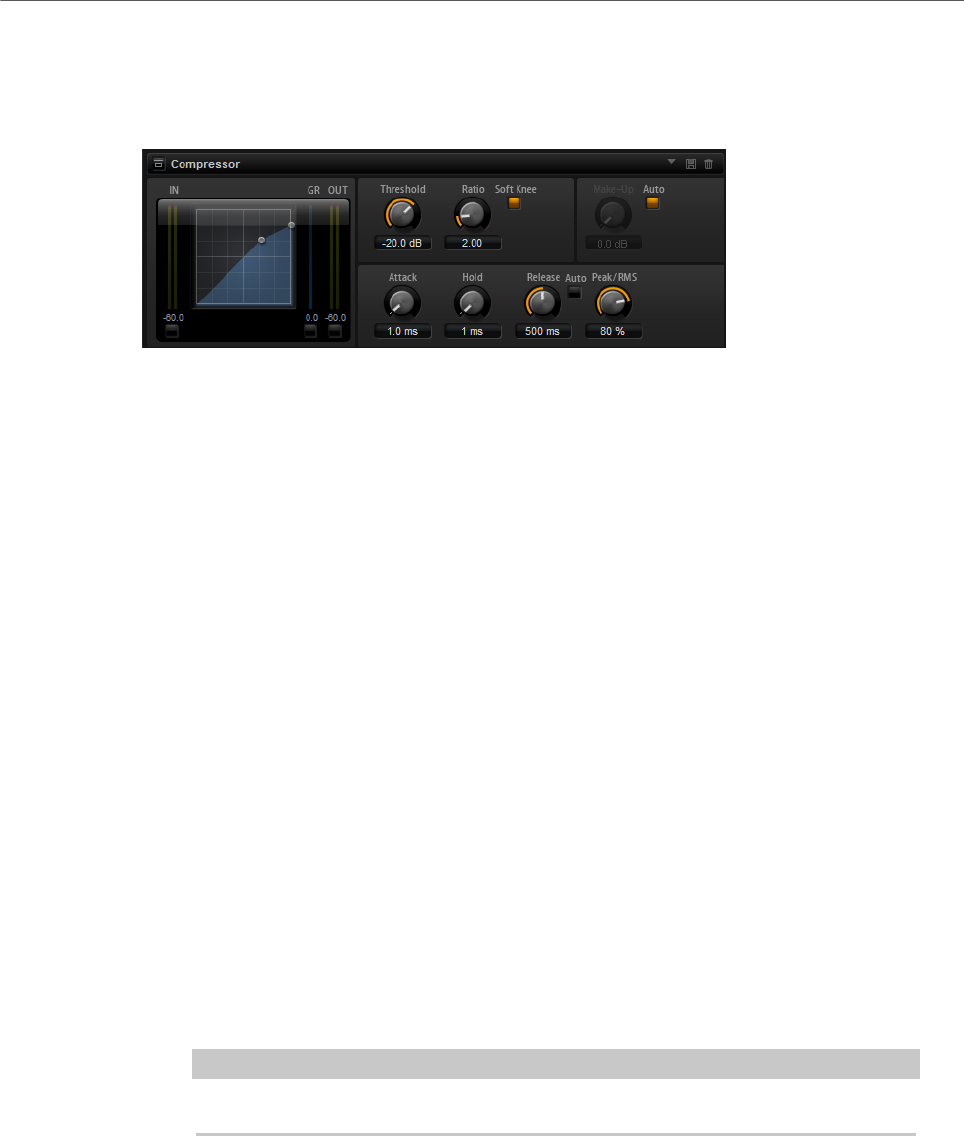
Effects Reference
Dynamics Effects
242
Compressor
The Compressor reduces the dynamic range of a sound. This way, the sound gains
headroom. You can use this extra headroom to make the overall sound louder again.
The graphical control to the left indicates the compression curve. You can edit the Threshold
and Ratio values with the handles of this control. The input and output VU meters indicate
the level before and after the compression. The Gain Reduction meter indicates the current
attenuation of the level.
Threshold
Sets the threshold. Sounds that are louder than the threshold are reduced in
gain. Sounds below the threshold stay untreated.
Ratio
Sets the amount of gain reduction for sounds that are louder than the threshold.
The higher the ratio, the more the output is lowered. For example, if the ratio is
set to 2:1 and the amplitude of the sound is 4 dB above the threshold, the output
is lowered by 2 dB. If the amplitude is 8 dB above the threshold, the output is
lowered by 4 dB.
Soft Knee
If this button is deactivated, signals above the threshold are compressed instantly
according to the set ratio. If Soft Knee is activated, the onset of the compression
is more gradual, producing a less drastic result.
Make-Up
Raises the overall sound. This can become necessary if too much gain reduction
is introduced by the Threshold and Ratio parameters. You can see the amount of
gain reduction in the Gain Reduction meter.
NOTE
This parameter is not available if the Auto button is activated.
Auto Make-Up Gain
Sets the Make-Up value automatically, depending on the current Threshold and
Ratio settings.
Attack
Determines how fast the Compressor reacts to sounds that exceed the threshold.
The longer the attack time, the longer the time it takes to reduce the gain. With
longer attack times, the onset of sounds exceeding the threshold pass through
unprocessed.
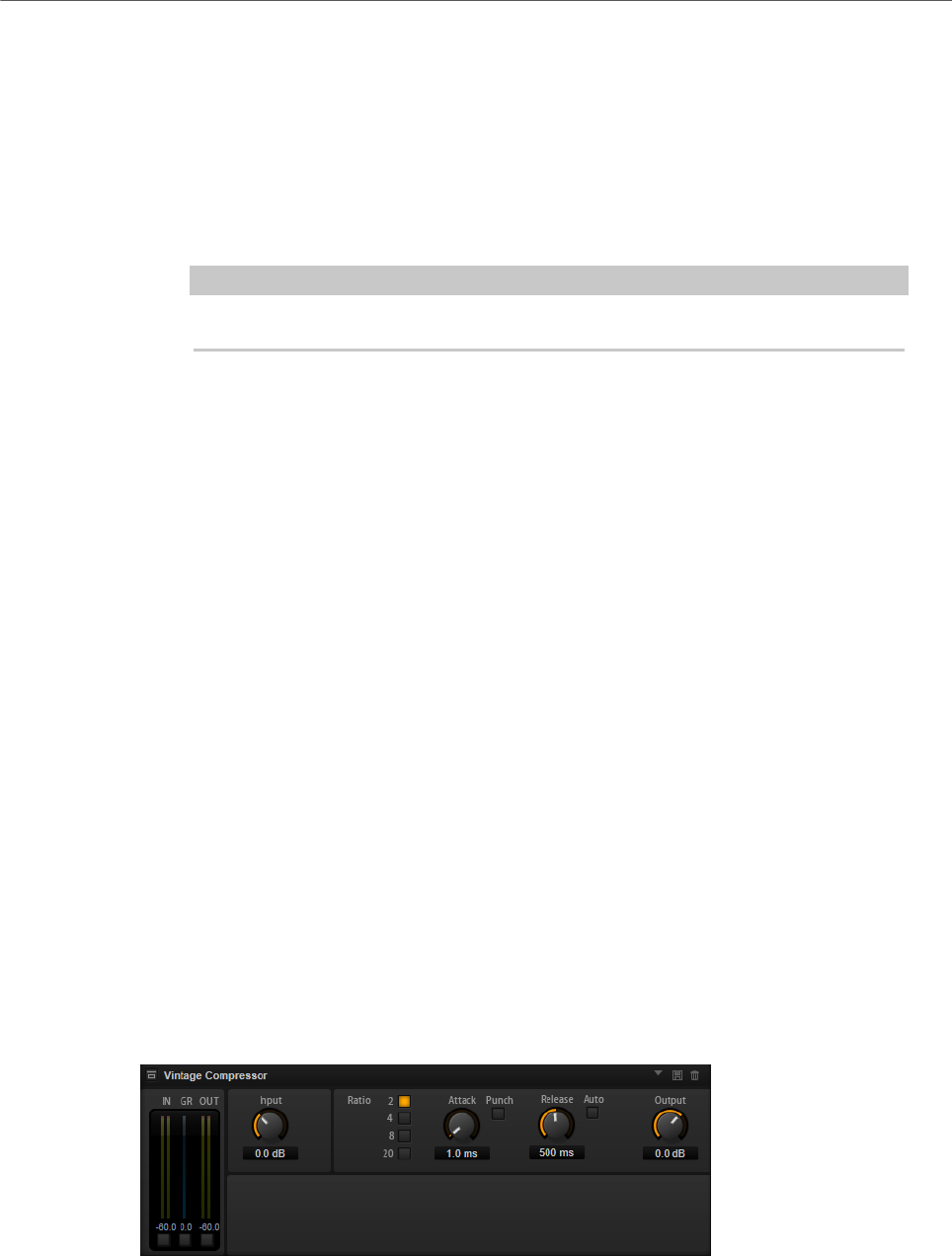
Effects Reference
Dynamics Effects
243
Hold
Sets the time period during which the compression is applied after the sound
exceeds the set threshold.
Release
Determines how fast the Compressor effect reacts to sounds that fall below the
set threshold. The longer the release time, the longer it takes to return to the
original level.
NOTE
This parameter is not available if the Auto Release button is activated.
Auto Release
Activate this to set the release time automatically. The Compressor analyzes the
input sound continuously to find the optimal setting.
Peak/RMS
Determines whether the input signal is analyzed according to peak or RMS values
or a mixture of both. At a setting of 0 %, the Compressor uses Peak sensing
only and at 100 %, RMS sensing only. Peak means that the Compressor directly
senses the peak level of the sound. RMS means that the Compressor senses the
average power of the sound. Peak sensing responds faster than RMS sensing.
Typically, Peak sensing is used for transient and RMS sensing for sustained
sounds.
Live
If this button is activated, the look-ahead feature of the effect is disengaged.
Look-ahead produces more accurate processing, but adds a certain amount
of latency as a trade-off. If Live mode is activated, there is no latency, which is
better for live processing.
Vintage Compressor
Vintage Compressor is modeled after vintage type compressors.
This compressor features separate controls for Input and Output gain, Attack, and Release.
In addition, there is a Punch mode which preserves the attack phase of the signal and a
program-dependent Auto feature for the Release parameter.
In/Out Meters
Show the highest peaks of all available input and output channels.
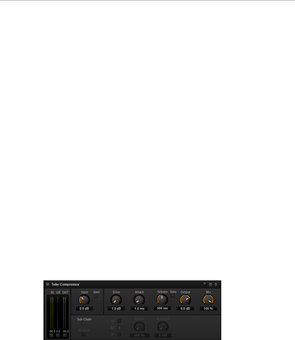
Effects Reference
Dynamics Effects
244
GR Meter
Shows the amount of gain reduction.
Input
Determines the compression amount. The higher the input gain, the more
compression is applied.
Ratio
Sets the amount of gain reduction for sounds that are louder than the threshold.
The higher the ratio, the more the output is lowered.
Attack (0.1 to 100 ms)
Determines how fast the compressor responds. If the attack time is long, more of
the initial part of the signal passes through unprocessed.
Punch
If this is activated, the early attack phase of the signal is preserved, retaining the
original punch in the audio material, even with short Attack settings.
Release (10 to 1000 ms or Auto mode)
Sets the time after which the gain returns to its original level. If the Auto button
is activated, the plug-in automatically finds the best release setting for the audio
material.
Output (-48 to 24 dB)
Sets the output gain.
Tube Compressor
This versatile compressor with integrated tube-simulation allows you to achieve smooth
and warm compression effects. The GR meter shows the amount of gain reduction. Tube
Compressor features an internal side-chain section that lets you filter the trigger signal.
In/Out Meters
Show the highest peaks of all available input and output channels.
GR Meter
Shows the amount of gain reduction.
Input
Determines the compression amount. The higher the input gain, the more
compression is applied.

Effects Reference
Dynamics Effects
245
Limit
Increases the ratio of the compressor for a limiting effect.
Drive (1.0 to 6.0)
Controls the amount of tube saturation.
Attack (0.1 to 100 ms)
Determines how fast the compressor responds. If the attack time is long, more of
the initial part of the signal passes through unprocessed.
Release (10 to 1000 ms or Auto mode)
Sets the time after which the gain returns to its original level. If the Auto button
is activated, the plug-in automatically finds the best release setting for the audio
material.
Output (-12 to 12 dB)
Sets the output gain.
Mix
Adjusts the mix between dry signal and wet signal preserving the transients of
the input signal.
Side-Chain
Activates the internal side-chain filter. The input signal can then be shaped
according to the filter parameters. Internal side-chaining is useful for tailoring
how the gate operates.
Monitor
Allows you to monitor the filtered signal.
Filter buttons (LP, BP, and HP)
If the Side-Chain button is activated, you can use these buttons to set the filter
type to low-pass, band-pass, or high-pass.
Center (50 to 20000 Hz)
If the Side-Chain button is activated, this sets the center frequency of the filter.
Q-Factor
If the Side-Chain button is activated, this sets the resonance or width of the filter.
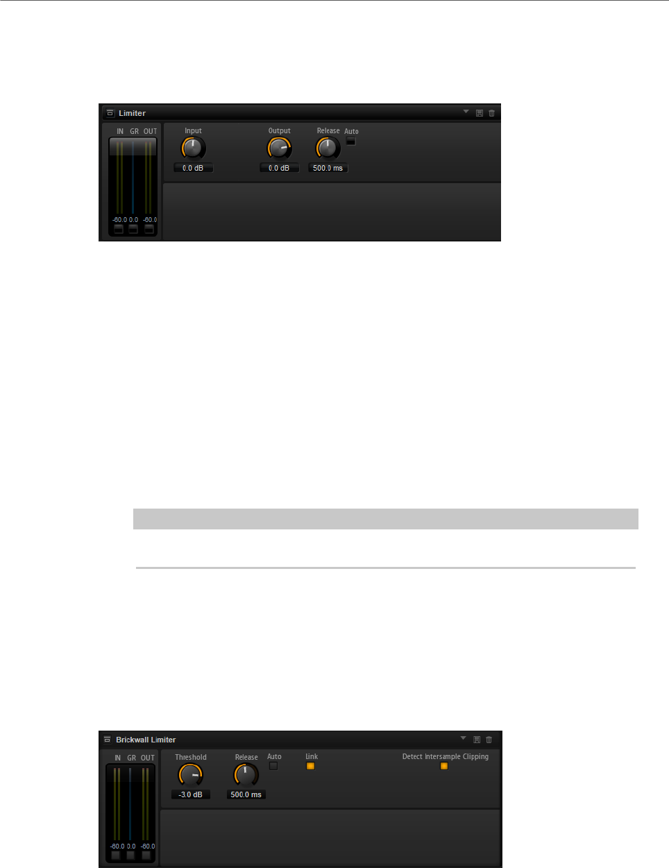
Effects Reference
Dynamics Effects
246
Limiter
The Limiter effect prevents the sound from exceeding the set output level. This can be used
to avoid clipping in following effects, for example.
The input and output meters indicate the level before and after the Limiter. The Gain
Reduction meter in the middle indicates the current attenuation of the level.
Input
Adjusts the input level of the sound. By increasing the input level, you can drive
the sound more and more into limiting.
Output
Sets the maximum output level of the sound.
Release
Sets the time that the gain needs to return to its original level. The longer the
release time, the longer it takes to return to the original level.
NOTE
This parameter is not available if the Auto button is activated.
Auto
Activate this to set the release time automatically. The Limiter analyzes the input
sound continuously to find the optimal setting.
Brickwall Limiter
Brickwall Limiter ensures that the output level never exceeds a set limit.
Due to its fast attack time, Brickwall Limiter can reduce even short audio level peaks without
creating audible artifacts. However, this plug-in creates a latency of 1 ms. Brickwall Limiter
features separate meters for input, output, and the amount of limiting.
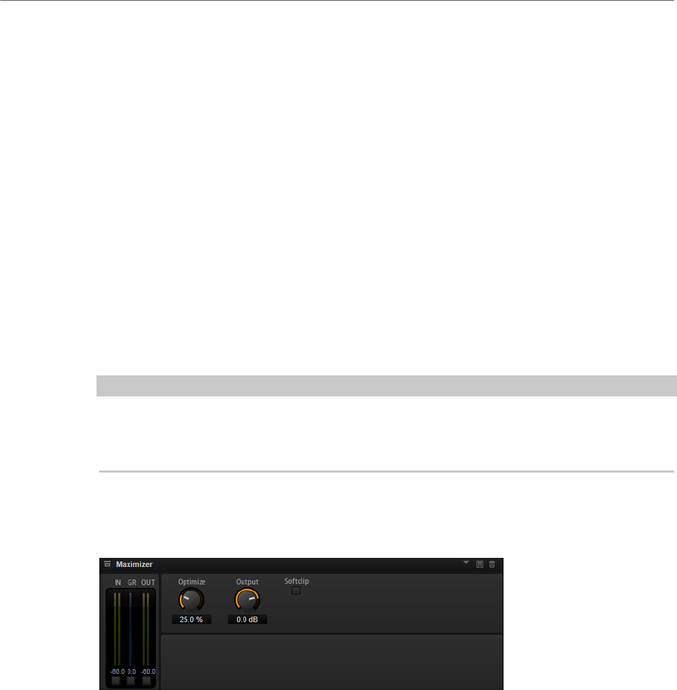
Effects Reference
Dynamics Effects
247
Threshold (-20 to 0 dB)
Determines the level where the limiter kicks in. Only signal levels above the set
threshold are processed.
Release (ms or Auto mode)
Sets the time after which the gain returns to the original level when the
signal drops below the threshold. If the Auto button is activated, the plug-in
automatically finds the best release setting for the audio material.
Link
If this button is activated, Brickwall Limiter uses the channel with the highest
level to analyze the input signal. If the button is deactivated, each channel is
analyzed separately.
Detect Intersample Clipping
If this option is activated, Brickwall Limiter uses oversampling to detect and limit
signal levels between two samples to prevent distortion when converting digital
signals into analog signals.
NOTE
Brickwall Limiter is designed for the reduction of occasional peaks in the signal. If the Gain
Reduction meter indicates constant limiting, try raising the threshold or lowering the overall
level of the input signal.
Maximizer
This plug-in raises the loudness of audio material without the risk of clipping.
Optimize
Determines the loudness of the signal.
Output
Sets the maximum output level.
Soft Clip
If this button is activated, Maximizer starts limiting or clipping the signal softly. At
the same time, harmonics are generated, adding a warm, tube-like characteristic
to the audio material.
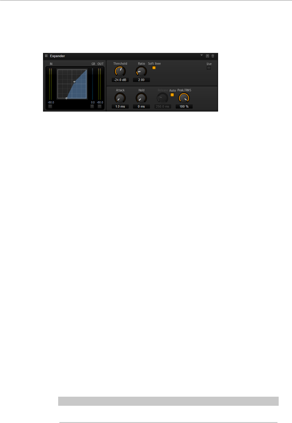
Effects Reference
Dynamics Effects
248
Expander
The Expander reduces the output level in relation to the input level for signals below the
set threshold. This is useful to enhance the dynamic range or reduce the noise in quiet
passages.
The graphical control to the left shows the expansion curve. You can edit the Threshold and
Ratio values with the handles of this control. The input and output meters indicate the level
before and after the expansion. The Gain Reduction meter indicates the current attenuation
of the level.
Threshold
Sets the threshold. Sounds that are softer than the threshold are reduced in gain.
Sounds above the threshold stay untreated.
Ratio
Sets the amount of gain reduction for sounds that are softer than the threshold.
The higher the ratio, the more the output is lowered. For example, if the ratio is
set to 2:1 and the amplitude of the sound is 4 dB below the threshold, the output
is lowered by 2 dB. If the amplitude is 8 dB below the threshold, the output is
lowered by 4 dB.
Soft Knee
If this button is deactivated, signals above the threshold are compressed instantly
according to the set ratio. When Soft Knee is activated, the onset of the expansion
is more gradual, producing a less drastic result.
Attack
Determines how fast the Expander reduces the gain when the sound falls below
the set threshold. The longer the attack time, the longer it takes to reduce the
gain.
Hold
Sets the time period during which the expansion is applied after the sound falls
below the set threshold.
Release
Determines how fast the Expander effect raises the gain after the sound exceeds
the set threshold. The longer the release time, the longer it takes to raise the
gain.
NOTE
This parameter is not available when the Auto Release button is activated.
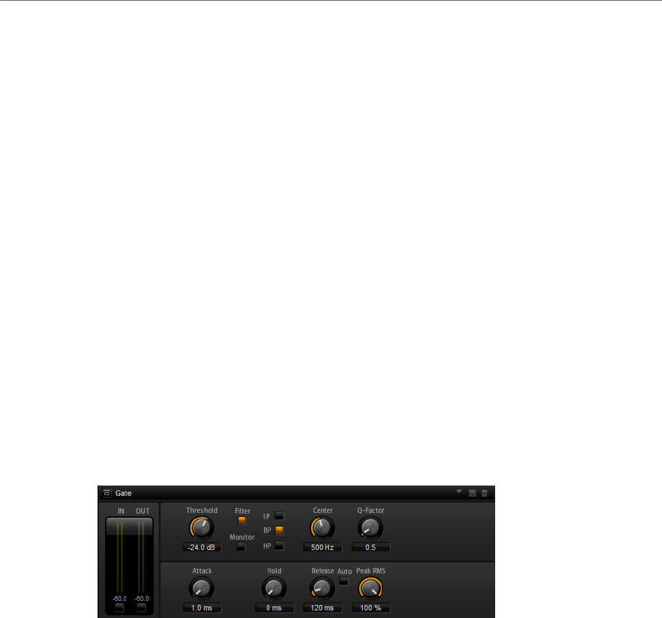
Effects Reference
Dynamics Effects
249
Auto
Activate this to set the release time automatically. The Expander analyzes the
input sound continuously to find the optimal setting.
Peak/RMS
Determines whether the input signal is analyzed according to peak or RMS values
or a mixture of both. At a setting of 0 %, the Expander uses Peak sensing only and
at 100 %, RMS sensing only. Peak means that the Expander directly senses the
peak level of the sound. RMS means that the Expander senses the average power
of the sound. Peak sensing responds faster than RMS sensing. Typically, Peak
sensing is used for transient and RMS sensing for sustained sounds.
Live
If this button is activated, the look-ahead feature of the effect is disengaged.
Look-ahead produces more accurate processing, but adds a certain amount
of latency as a trade-off. If Live mode is activated, there is no latency, which is
better for live processing.
Gate
The Gate effect passes sound only to its output if the input sound exceeds the set threshold.
Sounds below the threshold are silenced.
An internal side-chain filter allows you to analyze a filtered version of the input sound
instead. This way, the gate detects only certain frequencies of the input sound.
Threshold
Determines the level that activates the gate. Signal levels above the set threshold
trigger the gate to open, and signal levels below the set threshold close the gate.
Filter
Activates the internal side-chain filter. If this button is activated, the input sound
is filtered before it is analyzed. The gate opens only if the filtered sound exceeds
the set threshold. When the Filter button is deactivated, the filter controls are not
available.
Filter Type
Sets the filter type for the side-chain filter. Select high-pass (HP) to detect high
frequencies, band-pass (BP) to detect mid frequencies, and low-pass (LP) to
detect low frequencies only.

Effects Reference
Dynamics Effects
250
Monitor
Activate this button to listen to the sound of the side-chain filter. The gate is
inactive when the Monitor button is activated.
Center
Sets the center frequency of the side-chain filter.
Q-Factor
Adjusts the bandwidth of the filter from wide to narrow.
Attack
Determines how fast the gate opens when the sound exceeds the set threshold.
The longer the attack time, the longer it takes for the sound to fade in.
Hold
Sets the time period during which the gate is applied after the sound falls below
the set threshold.
Release
Determines how fast the gate closes after the sound falls below the set
threshold. The longer the release time, the longer it takes for the sound to fade
out.
NOTE
This parameter is not available when the Auto button is activated.
Auto
Activate this to set the Release time automatically. The Gate analyzes the input
sound continuously to find the optimal setting.
Peak/RMS
Determines whether the input signal is analyzed according to peak or RMS values
(or a mixture of both). At a setting of 0 %, the Gate uses Peak sensing only and
at 100 %, RMS sensing only. Peak means that the Gate directly senses the peak
level of the sound. RMS means that the Gate senses the average power of the
sound. Peak sensing responds faster than RMS sensing. Typically, Peak sensing
is used for transient and RMS sensing for sustained sounds.
Live
If this button is activated, the look-ahead feature of the effect is disengaged.
Look-ahead produces more accurate processing, but adds a certain amount
of latency as a trade-off. If Live mode is activated, there is no latency, which is
better for live processing.
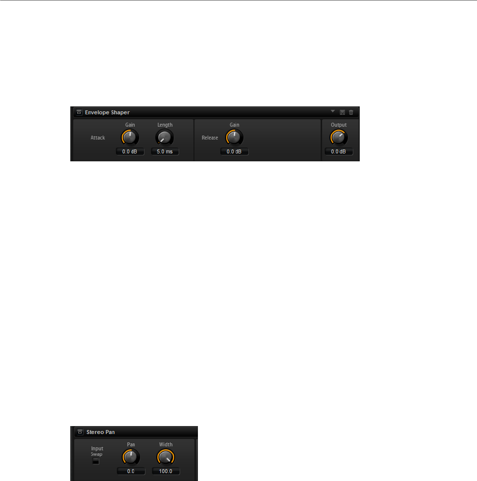
Effects Reference
Spatial and Panner Effects
251
Envelope Shaper
This effect can be used to attenuate or boost the gain of the attack and release phase of
audio material.
Be careful with levels when boosting the gain and, if needed, reduce the output level to avoid
clipping.
Attack – Gain
Changes the gain of the attack phase of the signal.
Attack - Length
Determines the length of the attack phase of the signal.
Release - Gain
Changes the gain of the release phase of the signal.
Output
Sets the output level.
Spatial and Panner Effects
Stereo Pan
This effect allows you to set the stereo position and width of the signal.
Input Swap
Swaps the stereo channels.
Pan
Sets the pan position of the signal. The panning is available for mono and stereo
input signals.
Width
Adjusts the stereo width of the signal from stereo to mono.

Effects Reference
Legacy Effects
252
Stereo Enhancer
This plug-in expands the stereo width of (stereo) audio material. It cannot be used with mono
files.
Width
Controls the width or depth of the stereo enhancement. Turn clockwise to
increase the enhancement.
Delay
Increases the amount of differences between the left and right channels to
further increase the stereo effect.
Color
Generates additional differences between the channels to increase the stereo
enhancement.
Mono
Switches the output to mono, to check for possible unwanted coloring of the
sound which sometimes can occur when enhancing the stereo image.
Legacy Effects
HALion 3 Legacy Effects
In addition to the standard effects, a number of effects from HALion 3 is also provided. These
effects can be selected from the Legacy submenu of the effects menu.
Hall Reverb
A simple reverb with adjustable pre-delay and damping.
PreDelay
Delays the wet signal to simulate larger acoustic spaces or to create a slap-back
effect.
Time
Length of reverb tail.
Damp
Progressive damping of high frequencies.
Low EQ
Low-cut EQ.
High EQ
High-cut EQ.
Mix
Wet/dry mix.

Effects Reference
Legacy Effects
253
Non-Linear Reverb
A gated reverb with a sharp cutoff.
Time
Length of reverb tail. It also allows you to change the sound from dense early
reflections to a trashy, grainy 1980’s-type reverb.
Low EQ
Low-cut EQ.
High EQ
High-cut EQ.
Mix
Wet/dry mix.
Early Reflections
A short, dense reverb for simulating small acoustic spaces and to thicken or blur sounds.
Time
Length of reverb tail. It also allows you to change the sound from dense early
reflections to a trashy, grainy 80’s-type reverb.
Low EQ
Low-cut EQ.
High EQ
High-cut EQ.
Mix
Wet/dry mix.
Delay
A simple mono-in/stereo-out delay.
Time
Delay time.
Sync
If Sync is activated, you can set the delay time in fractions of beats.
Feedback
Controls the number of delay repeats.
Balance
Ratio of left delay time to right delay time.

Effects Reference
Legacy Effects
254
Damp
High-cut filter to soften delay repeats.
Stereo Delay
A stereo-in/stereo-out delay.
Time
Delay time.
Feedback
Controls the number of delay repeats. For minimum feedback, set the slider to
the mid position. By moving the slider to the left or right, cross delay is applied,
where left output feeds back into right input or vice versa.
Sync
If Sync is activated, you can set the delay time in fractions of beats.
Balance
Ratio of left delay time to right delay time.
Damp
High-cut filter to soften delay repeats.
Long Delay
This effect provides the same parameter set as the Delay effect, except that longer delays of
up to four seconds can be set.
Tape Delay
Simulation of a vintage 4-head analog tape delay.
Time
Delay time.
Sync
If Sync is activated, you can set the delay time in fractions of beats.
Feedback
Controls the number of delay repeats.
Vintage
Amount of vintage color and tape flutter.
Mix
Wet/dry mix.
Head 1
Delay level 1 (the output is panned left).

Effects Reference
Legacy Effects
255
Head 2
Delay level 2 (the output is panned right).
Head 3
Delay level 3.
Head 4
Delay level 4.
Pan 3+4
Varies the panning of delays 3 and 4 from center to hard left/right.
Vol 3+4
Varies the volume of delay outputs 3 and 4.
Chorus
A straightforward chorus effect that can be used to widen sounds.
Rate
The modulation rate.
Depth
The amount of pitch modulation.
PreDelay
The initial delay, to vary the tightness of the chorused voices in relation to the dry
signal.
Mix
Wet/dry mix.
Ensemble
Chorus with a more complex modulation waveform for a lively thickening effect.
Rate
The modulation rate.
Depth
The amount of pitch modulation.
Shimmer
Creates a more complex modulation effect.
Width
Stereo width adjustment.
Mix
Wet/dry mix.

Effects Reference
Legacy Effects
256
Flanger
A classic flanger effect.
Rate
Sweep rate.
Depth
Sweep depth.
Feedback
Feedback amount. Increase for a more intense flanging effect.
PreDelay
Initial delay. Adjusts the minimum delay time/maximum flange frequency.
Mix
Wet/dry mix.
Phaser
A four pole phaser for subtle phasing effects.
Rate
Sweep rate.
Depth
Sweep depth.
Feedback
Feedback amount. Increase for a more pronounced effect.
Stereo
Offset between left and right modulation.
Center
Sets the center frequency around which the modulation occurs.
Mix
Wet/dry mix.
Pan & Tremolo
Autopan and Tremolo effect as used in vintage electric pianos.
Rate
Sweep rate.
Phase
Relative phase of left and right channel amplitude modulation, to vary from
tremolo to autopan.

Effects Reference
Legacy Effects
257
Shape
Shape of modulation waveform from thin pulse, through sine, to fat pulse.
Mix
Wet/dry mix.
Stereo Width
A stereo width enhancer with 4 modes.
Mode
•Adjust mode adjusts the existing width of the stereo signal.
•Swap mode adjusts the existing width of the stereo signal and additionally
swaps the left and right channels.
•Comb mode applies a stereo comb filter effect.
•Haas mode synthesizes the stereo width by delaying one channel.
Delay
Delay time (not used in Adjust and Swap modes).
Width
Overall width adjustment.
Low/Mid/High
Width adjustment for the low, mid, and high frequencies.
Output
Output level trim.
Rotary Speaker
Simulation of a rotary speaker cabinet with high and low rotors.
Rate
Master speed control: Stop, Slow, Fast.
Dirt
Amount of overdrive.
LoHi
Crossover frequency between low and high rotors.
Width
Stereo width.
Tone
Adjusts the tone of the overdriven signal.
Low/High Speed
Speed of the high and low rotors.

Effects Reference
Legacy Effects
258
Low/High Acceleration
Acceleration of the high and low rotors.
Mix
Wet/dry mix.
Wah Pedal
An auto-wah effect.
Rate
Modulation rate.
Depth
Modulation depth.
Pedal
Adjusts the filter frequency.
Mode
•Auto Wah: Envelope controlled wah effect.
•Pedal Wah: No modulation. The Pedal parameter sets the frequency.
•Mod Wah: LFO modulation. The Rate parameter controls the modulation
rate.
Resonance
Sets the amount of filter resonance.
Tracking
Adjusts the envelope tracking speed in Auto mode, and the envelope rate
modulation in Mod mode.
Mix
Wet/dry mix.
TalkBox
Modulated vowel formant filter.
Rate
LFO modulation rate.
Depth
LFO modulation depth.
Vowel
In center setting, vowels are produced when there is no modulation.
Env Mod
Amount of vowel modulation by input signal level.

Effects Reference
Legacy Effects
259
Env Att
Rate of response to a rising input signal level.
Env Rel
Rate of response to a falling input signal level.
Mix
Wet/dry mix.
Shelf EQ
Simple tone control.
Output
Output level trim.
Bass
Low frequency cut/boost.
Treble
High frequency cut/boost.
Parametric EQ
Two-band parametric equalizer.
Gain 1/2
Cut/boost amount for the two bands.
Freq 1/2
Sets the center frequency for the two bands.
Width 1/2
Sets the bandwidth for the two bands (Q).
Output
Output level trim.
Enhancer
Psycho acoustic spectrum shaping.
High Depth
High frequency boost, combined with mid cut.
High Tune
High/mid tune.
Low Depth
Low frequency boost.

Effects Reference
Legacy Effects
260
Low Tune
Low frequency tune.
Limiter
Hard level limiting.
Drive
Input signal drive.
Attack
Attack time.
Release
Release time.
Output
Output level trim.
Compressor
A simple compressor effect.
Threshold
Compression threshold.
Ratio
Compression amount.
Attack
Attack time.
Release
Release time.
Output
Output level trim.
Multiband
Three-band compressor.
Drive
Input signal drive (increase for more density).
Lo/Hi
Balance of low and high frequency bands.
Mid
Level of mid frequency band.

Effects Reference
Legacy Effects
261
Attack
Attack time.
Release
Release time.
Output
Output level trim.
Gate
Simple gate effect.
Threshold
Gate threshold.
Range
Level reduction when gate closed.
Attack
Attack time.
Release
Release time.
Output
Output level trim.
Distortion
Hard clipping distortion.
Drive
Distortion amount.
Bias
Adjusts the balance between even and odd harmonics, that is, the character of
the distortion.
Tone
Distortion tone.
Out
Output level trim.
Mix
Wet/dry mix.
Overdrive
Softer distortion with a gradual onset.

Effects Reference
Legacy Effects
262
Drive
Overdrive amount.
Bias
Overdrive character. Adjusts the balance between even and odd harmonics.
Out
Output level trim.
Mix
Wet/dry mix.
Bit Reduction
Digital, lo-fi, quality degradation.
Mode
Determines whether the bit depth is fixed (Linear) or depends on the signal level
(Companding).
Rate
Simulated sample rate.
Depth
Sample bit depth.
Slew Rate
Maximum rate of change of output waveform, for a soft, wooly distortion.
Mix
Wet/dry mix.
Amp Simulator
Amplifier modeling effect.
Model
The type of amplifier model. This changes the tone character.
Mode
Mono/Stereo operation. Mono saves CPU, and in some cases sounds more solid.
Drive
Overdrive amount.
Feedback
Feedback amount. The result depends on the input signal.
Treble
Treble boost. Optionally in or out of phase for different tones.

Effects Reference
Legacy Effects
263
Mix
Wet/dry mix.
Modulate L/R
This effect features three modes of signal distortion, where one side of a stereo signal is
used to modulate the other.
Mode
•Ring Mod: Ring modulation.
•Env Mod: The signal level of the right channel is modulated by the level of
the left channel.
•Duck: The signal level of the right channel is reduced when the level of the
left channel increases.
Thru
Defines which input signals are used as the dry signal for the Mix.
Smooth
Smoothing of modulation.
Drive
Level trim.
Mix
Wet/dry mix.
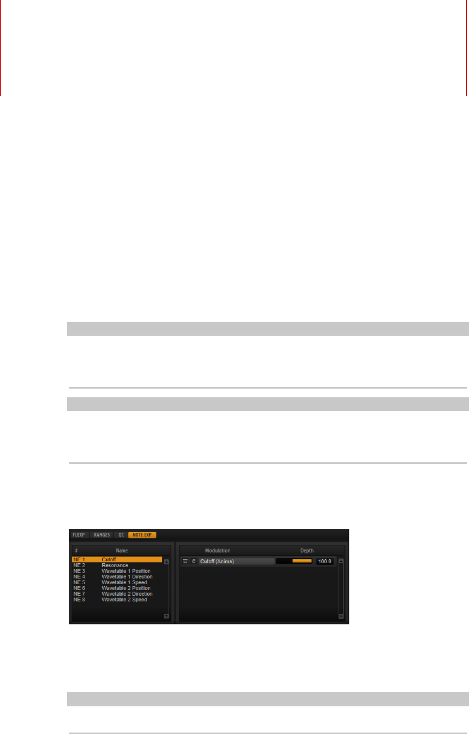
Note Expression
264
Steinberg’s Note Expression technology was developed for creating realistic instrument
performances. Note Expression allows you to create automated modulations for each note.
HALion Sonic supports Note Expression for volume, pan, and tuning. If you use a Steinberg
DAW that supports Note Expression, you can automate the Note Expression parameters for
any program in HALion Sonic per note.
Furthermore, in programs that give you access to the modulation matrix, you can assign up
to eight Note Expression controllers to the available modulation destinations. These work in
addition to the preassigned pitch, pan, and level modulations.
NOTE
The Note Expression controllers of a program are shared by all its layers. This means that
the controller data affects all layers simultaneously. Depending on how the Note Expression
controllers are set up, each layer can react differently.
NOTE
If you use HALion Sonic with host applications that do not support Note Expression, the Note
Expression editor page and the Note Expression controllers in the modulation matrix are
visible, but they do not have any influence on the program.
Note Expression Editor
• To open the Note Expression editor, open the Edit page and select the Program tab.
The editor shows the Note Expression controllers on the left and the assigned modulation
destinations on the right. This gives you a quick overview of how the Note Expression
controllers are routed in the modulation matrix and what their influence on the sound will
be.
NOTE
A Note Expression controller can be assigned to several destinations.

Note Expression
Note Expression Editor
265
Name
If you assign a Note Expression controller for the first time, it gets the name of
the modulation destination that it is assigned to. Any further assignments do not
change the name. You can specify a name manually by entering it in the Name
field.
Bypass Note Expression Controller
To deactivate the effect of the controller, click the Bypass Note Expression
Controller button. It is linked to the Bypass button of the corresponding
modulation destination in the modulation matrix.
Depth
This slider adjusts the intensity of the Note Expression modulation. It is linked to
the Depth slider of the corresponding modulation destination in the modulation
matrix.
Edit
Click Edit to jump to the first modulation assignment of the Note Expression
controller in the modulation matrix.
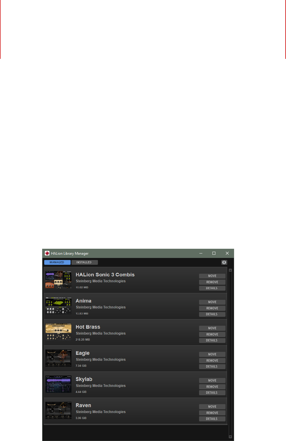
Library Manager
266
HALion Sonic’s Library Manager allows you to register and to manage libraries that have
been created with HALion 6 and newer. It also displays all libraries that were created earlier
and therefore were installed with a classic installer.
The Library Manager is installed on your computer as a standalone application and can be
run independently from HALion, HALion Sonic, and HALion Sonic SE.
For actions such as registering, moving, or deleting libraries, the Library Manager requires
full access to all VST Sound libraries. Therefore, you must close HALion, HALion Sonic,
HALion Sonic SE, and your Steinberg DAW first, so that they release these files.
Library Manager Editor
All libraries are displayed in the Library Manager, either on the Managed or the Installed
tab. For each library, an icon, the name, the manufacturer, as well as its total file size are
shown.

Library Manager
Library Manager Editor
267
• The libraries in the Managed list were created with HALion 6 and newer and can be
moved between hard disks or deleted.
• The libraries on the Installed list were installed using an installer. These libraries
cannot be moved or deleted, to avoid interference with the original installers.
For both library types, a Details button is available, which will extend the list entry and show
which VST Sound containers are part of the library and where on your hard disks they are
located.
Installing VST Sound Libraries
To install a new library, you must register the corresponding VST Sound container files.
PREREQUISITE
You have moved the VST Sound container files to a hard disk and folder where you want to
store them and from where you want to register them.
NOTE
If you have downloaded a library, for example, you most probably do not want to keep it in
the Downloads folder. To keep your system clean and uncluttered, you might want to create
a dedicated folder for all your libraries and then create subfolders for each new library. You
can also create multiple Library folders on different hard disks.
PROCEDURE
•Navigate to the folder where the new VST Sound container files are located and
double-click one of them.
The Library Manager opens and registers all VST Sound containers from that folder.
This process does not change the location of the library files, but registers them to the
MediaBay of HALion, HALion Sonic, and HALion Sonic SE, as well as your Steinberg
DAW.
NOTE
•If the folder contains VST Sound containers that have already been registered,
they are ignored.
•You can also register user VST Sound containers that were created with versions
4 and 5 of HALion. HSB files from HALion 3 are not supported.
RESULT
All VST Sound containers in that folder are now registered and can be used the next time that
you open HALion Sonic.
Moving Libraries
You can move the file location of a library, for example, to a faster SSD hard disk or because
you have accidentally registered it from the wrong folder and you do not want it to remain in
this location.
PROCEDURE
1. Navigate to the library in the list and click Move.

Library Manager
Library Manager Editor
268
2. In the dialog, navigate to the new location and click OK.
Removing Libraries
You can remove a library if it is no longer needed.
PROCEDURE
1. Navigate to the library in the list and click Remove.
2. Do one of the following:
•To delete the library from your hard disk, select Move to Trash.
•To unregister the library while keeping the corresponding VST Sound container,
select Unregister.
NOTE
•Libraries can have dependencies to other libraries. For example, if a preset
library is based on samples that were delivered exclusively with another library.
If you try to delete this second library, the Library Manager will warn you that
this library is required by another library.

Using the Standalone Version
of the Plug-In
269
If you use HALion Sonic as a standalone application, an additional section is available at the
top of the control panel. Here, you can define key commands, set up audio and MIDI interface
routings, adjust the master volume, and access the integrated MIDI scratch pad, which
allows you to record your musical ideas without having to start a MIDI sequencer application.
It can also be used to play multitrack arrangements that trigger the different programs.
Making Preferences Settings
You can configure the standalone version of HALion Sonic in the Plug-In Preferences dialog.
•To open the Plug-In Preferences dialog, click the Open Preferences button to the
right of the audio output field or right-click in the topmost section of the control panel
and select Plug-In Preferences on the context menu.
Preferences Dialog
The Plug-In Preferences dialog has several pages on which you can make settings.
MIDI Page
MIDI Input Ports
Use this pop-up menu to specify a MIDI input.
Channel Filter
Determines whether MIDI events are recorded on all MIDI channels, or only on
one specific channel.
Filter ‘All Notes Off’ Controller
Activate this parameter to avoid unwanted “All Notes Off” messages. Such
messages are sent by some keyboards when the last key is released. This causes
HALion Sonic to stop playback, even when the sustain pedal is still in use.
Outputs Page
You can use the Audio Output Ports pop-up menus to assign different audio outputs. You can
assign different audio outputs for each channel.
• To map an output to a channel, select it from the pop-up menu.
• To set the front and rear channels to incrementing audio output ports, hold down Shift
and select an audio output.

Using the Standalone Version of the Plug-In
Preferences Dialog
270
• To assign the audio outputs in pairs to the front and rear channels, hold down Alt-Shift
and select an audio output.
Metronome Page
On the Metronome page, a number of settings can be made regarding the use of a
metronome.
Mode
Activates/Deactivates the metronome or sets it to Count In mode.
Accent
Accentuates the first beat of each bar.
Level
Adjusts the volume of the metronome.
Connections
Allows you to select a separate stereo output for the metronome.
General Page
• If you want the plug-in to close without prompting when you quit the program, activate
Don’t prompt for confirmation when quitting HALion Sonic.
ASIO Driver Page
On the ASIO Driver pop-up menu, you can select your audio hardware driver.
Release Driver when Application is in Background
Activate this option if you plan to use several audio applications simultaneously.
Input Latency/Output Latency
The input and output latency values for your audio hardware are displayed.
Latency is the amount of time it takes for your system to respond to any
messages that are sent to it. High latency results in a noticeable delay between
when you press a key and when you hear the sound.
You can change the latency with the Buffer Size parameter in the control panel
for your driver, opened by clicking the Control Panel button on the Advanced tab.
Sample Rate
Below the latency values, you can set the sample rate for the connected audio
hardware.
Audio Priority
Determines which of the HALion Sonic processes gets priority when accessing
processor resources on your computer.
• In Normal mode, non-audio processes and audio playback get roughly
equal priorities.
• In Boost mode, audio precedes MIDI in priority. Try this mode if audio
playback problems occur when playing back MIDI and audio material.
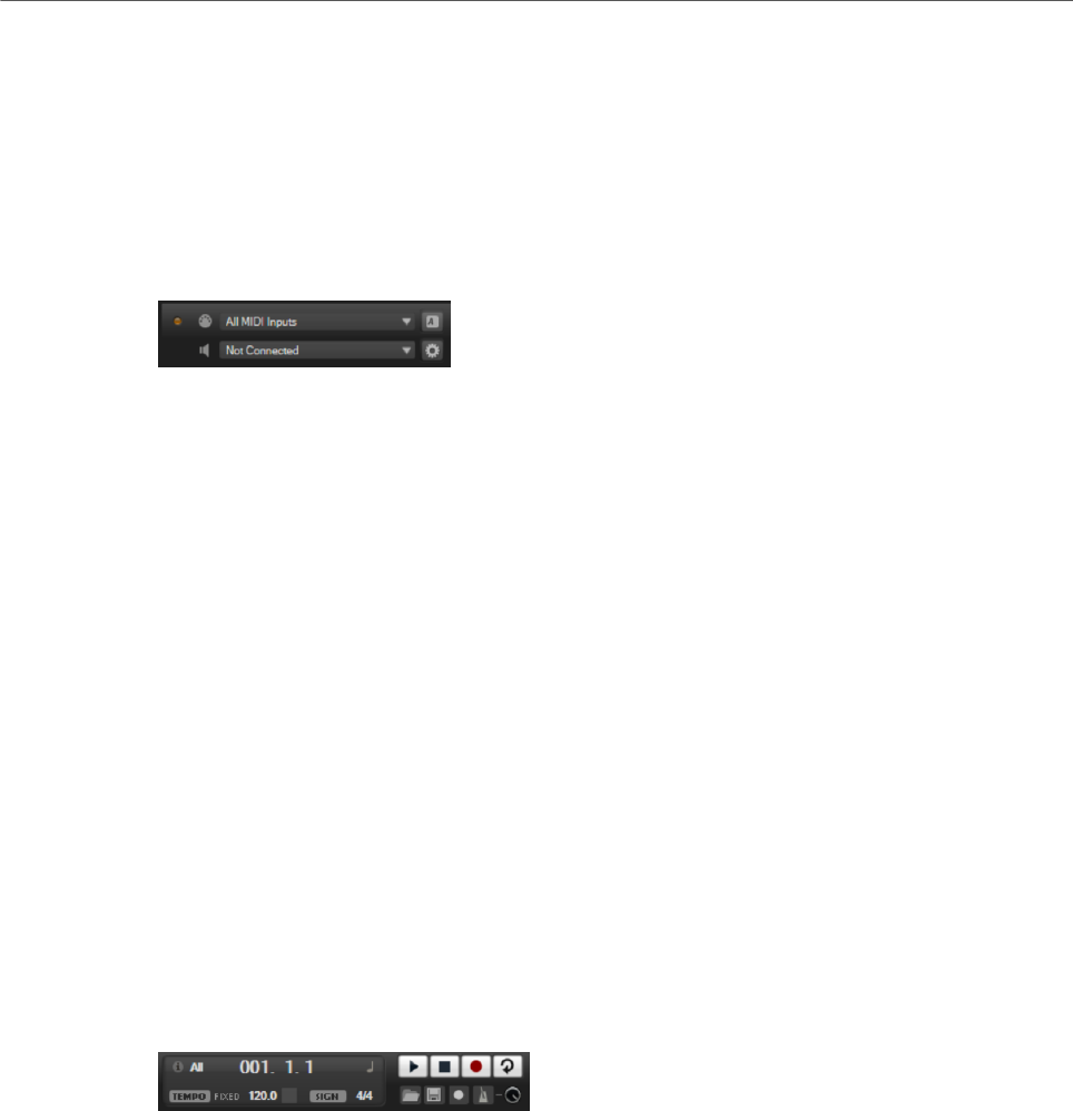
Using the Standalone Version of the Plug-In
Selecting the MIDI Input and the Audio Output
271
Advanced Page
Once you have selected the driver, you can specify which inputs and outputs to use and
name these on the Advanced page. Click the Control Panel button to open the control panel
for the audio hardware and adjust the settings as recommended by the audio hardware
manufacturer.
Selecting the MIDI Input and the Audio Output
The MIDI input pop-up menu lists all MIDI devices that are installed on your system.
• Select the MIDI device that you want to use from the MIDI Input pop-up menu.
The MIDI activity LED in the top left corner of the control panel indicates incoming
MIDI messages via the selected MIDI input. The LED lights up on receiving note-on and
controller messages. This way, you can check if HALion Sonic and your MIDI keyboard
are connected to the same MIDI device input.
The Audio output pop-up menu lists all outputs of the selected ASIO device.
• To select an audio output for the main stereo channel of the plug-in, open the Audio
Output pop-up menu.
If you select an audio output, the front and rear channels are set to incrementing
audio output ports. To assign the audio outputs in pairs to the front and rear channels
instead, hold down Alt-Shift and select an output.
RELATED LINKS
ASIO Driver Page on page 270
Scratch Pad
The scratch pad allows you to record and play back MIDI files in Standard MIDI File format.
You can load existing MIDI files and you can record your own files and save them.
The transport section provides buttons for play, stop, record, and loop. The display shows
the song position, the tempo, and the time signature of the MIDI file. In addition, there is a
metronome that you can use for recording and practicing.
The scratch pad can play back multi-track MIDI files sending notes on all 16 MIDI channels.
It also sends MIDI program change messages when a MIDI file is loaded.
Transport Controls
Play
Click Play to start playback of the MIDI file. Playback always starts at the song
position.

Using the Standalone Version of the Plug-In
Scratch Pad
272
Stop
Click Stop to pause the MIDI file at the current position. Click the button twice to
reset the song position to the start.
Record
Click Record to start recording.
Loop
Activate Loop to play the entire MIDI file in a loop.
Info Icon
To check which MIDI file is loaded, point the mouse at the info icon in the top left corner of
the scratch pad. A tooltip appears, showing the name of the MIDI file.
Song Position Indicator
The song position indicator shows the position of the transport. Above the song position
indicator, the position is displayed numerically.
After loading a MIDI file, the display shows the full length of the file.
•To move the transport to a different song position, drag the song position indicator to
the new position.
•To switch the time format between Time and Bars, click Select Time Format in the top
right corner of the display.
Tempo and Time Signature
Below the song position display, the Tempo and Time Signature fields are located. These
fields provide HALion Sonic with tempo and time signature information. These settings are
used by the scratch pad and the metronome.
Fixed Tempo/Tempo Track
Set this parameter to Track to follow the original tempo of the MIDI file.
Set this parameter to Fixed to enter the tempo manually. You can either enter the
value directly in the value field or you can enter a tempo by repeatedly clicking
the Tap to set Tempo field next to the value field.
Tempo Value
Determines the tempo of the MIDI file.
Adjust Tempo
If the Tempo Track option is selected, this parameter is available, allowing you to
scale the playback relatively to the original tempo of the MIDI file.
Time Signature
Determines the time signature. You can enter the new signature as fractions of
beats.

Using the Standalone Version of the Plug-In
Loading a MIDI File
273
Recording Your Performance
PROCEDURE
1. Click the record symbol below the Record button to select a record mode.
•To start recording immediately when you click the record button, select Direct.
•To start recording with the first MIDI note, select MIDI.
•To start the recording after a count-in of one bar, select Count In 1.
•To start the recording after a count-in of 2 bars, select Count In 2.
2. Click the Record button to start recording.
To indicate that the recording is running, the song position indicator moves from left to
right.
3. When you are done recording, click the Stop button.
RELATED LINKS
Saving a MIDI File on page 274
Using the Metronome
PROCEDURE
•To select the playback mode of the metronome, click Metronome and select one of the
options from the pop-up menu:
•If On is selected, the metronome is activated and plays continuously.
•If Count In is selected, the metronome plays only during the count-in of a
recording.
•To deactivate the metronome, select Off.
Loading a MIDI File
You can load MIDI files in Standard MIDI File format (file name extension .mid).
PROCEDURE
1. Click the Load MIDI File button below the transport buttons.
2. In the file dialog, select the file that you want to use.
3. Click Open to load the MIDI file.
MIDI Channel Filter
If a multitrack MIDI file is loaded, you can play back all MIDI events or only the events of a
specific MIDI channel.
• To specify which events to play back, click the MIDI Channel Filter field to the right of
the info icon and select an option from the pop-up menu.

Using the Standalone Version of the Plug-In
Saving a MIDI File
274
Saving a MIDI File
PROCEDURE
1. Click the Save MIDI File button below the transport buttons.
2. In the file dialog, specify a location and a file name.
3. Click Save to save your recorded performance as a MIDI file.
Master Volume
Use the volume control on the right to set the master volume of the outputs of the
standalone version of HALion Sonic. This includes the volume of the main outputs, the rear
outputs, and the output of the metronome.

Index
275
A
Anima
About 153
Audio Output 271
Auron
About 109
B
B-Box
About 139
D
Delay Effects 214
Distortion Effects 225
Dynamics Effects 241
E
Eagle
About 186
Edit Page
Amplifier Tab 46
AUX Tab 58
Envelopes 48
Expressions Section 59
Filter Tab 43
Inserts 61
Keymap Tab 58
LFO Tab 54
Oscillator Tab 40
Pitch Tab 40
Voice Tab 36
Effect Slots 107
Effects 106
About 107
Amplifier 225
Auto Filter 217
Brickwall Limiter 246
Chorus 230
Compressor 242
Distortion 226
DJ-EQ 217
Envelope Shaper 251
Expander 248
Flanger 231
Frequency Shifter 236
Gate 249
Graphic EQ 216
Limiter 246
Maximizer 247
MorphFilter 221
Multi Delay 214
Octaver 229
Phaser 233
Resonator 221
Reverb 211
REVerence 210
Ring Modulator 234
Rotary 238
Step Flanger 232
Stereo Pan 251
StereoEnhancer 252
Studio EQ 215
Tape Saturator 228
Tremolo 234
Tube Compressor 244
Tube Saturator 229
Using 107
Vibrato 240
Vintage Compressor 243
Vintage Ensemble 241
VST Amp 227
WahWah 224
Effects Page 107
Envelopes
About 48
Selecting Nodes 51
Setting up the Loop 54
EQ Effects 215
F
Filter Effects 217
FlexPhraser 76
H
HALion 3 Effects 252
HALiotron
About 137
Hot Brass
About 188
I
Insert Effects
About 61

Index
276
K
Keymap
About 58
L
Layers
Editing 36
Legacy Effects 252
M
Macro Pages
About 88
Master Section 16
MediaBay
About 93
Filters 93
Managing files 93
Results List 94
MIDI Controllers
About 103
Assigning 103
Factory Controller Assignment 105
Parameter Range 104
MIDI File
Loading 273
MIDI Input 271
MIDI Page 102
Mix Page
About 106
Mixing 106
Model C
About 131
Modulation Effects 230
Modulation Matrix
About 64
Multis
About 88
N
Note Expression
About 264
Editor 264
O
Options Page 26
P
Panner Effects 251
Pitch Shift Effects 229
Preferences Dialog 269
Preferences Settings 269
Presets
About 88
Module Presets 13
VST Presets 13
Program Page
Parameters 32
Program Slot Section 15
Programs 32
About 88
Editing 32
Loading 89
Q
Quick Control Assignments 21
Quick Controls 18
Bypassing 23
Managing 22
R
Raven
About 185
Reverb Effects 210
S
Skylab
About 171
Spatial Effects 251
Standalone Plug-In Version
About 269
Saving MIDI Files 274
Studio Strings
About 199
T
Trigger Pads 24
Trium
About 117
V
Voltage
About 125
W
World Instruments
About 145
World Percussion
About 149
