Steinberg Cubase AI – Operation Manual 5.0 OM
User Manual: Steinberg AI - 5.0 - Operation Manual Free User Guide for Cubase Software, Manual - page1
Open the PDF directly: View PDF ![]() .
.
Page Count: 284 [warning: Documents this large are best viewed by clicking the View PDF Link!]
- Table of Contents
- About this manual
- VST Connections: Setting up input and output busses
- The Project window
- Playback and the Transport panel
- Recording
- Fades, crossfades and envelopes
- The mixer
- Audio effects
- VST Instruments and Instrument tracks
- Automation
- Audio processing and functions
- The Sample Editor
- The Audio Part Editor
- The Pool
- Working with Track Presets
- Remote controlling Cubase AI
- MIDI realtime parameters
- MIDI processing and quantizing
- The MIDI editors
- Introduction
- Opening a MIDI editor
- The Key Editor - Overview
- Key Editor operations
- The Drum Editor - Overview
- Drum Editor operations
- Working with drum maps
- Using drum name lists
- The List Editor - Overview
- List Editor operations
- Working with System Exclusive messages
- Recording System Exclusive parameter changes
- Editing System Exclusive messages
- The Score Editor - Overview
- Score Editor operations
- Editing tempo and signature
- Export Audio Mixdown
- Synchronization
- Video
- File handling
- Customizing
- Key commands
- Index

Operation Manual
Cristina Bachmann, Heiko Bischoff, Marion Bröer, Sabine Pfeifer, Heike Schilling
The information in this document is subject to change without notice and does not represent a commitment on the part
of Steinberg Media Technologies GmbH. The software described by this document is subject to a License Agreement
and may not be copied to other media except as specifically allowed in the License Agreement. No part of this publica-
tion may be copied, reproduced or otherwise transmitted or recorded, for any purpose, without prior written permission
by Steinberg Media Technologies GmbH.
All product and company names are ™ or ® trademarks of their respective owners. Windows XP is a trademark of
Microsoft Corporation. Windows Vista is a registered trademark or trademark of Microsoft Corporation in the United
States and/or other countries. The Mac logo is a trademark used under license. Macintosh and Power Macintosh are
registered trademarks.
Release Date: June 04, 2009
© Steinberg Media Technologies GmbH, 2009.
All rights reserved.
Table of Contents
4
Table of Contents
7About this manual
8Welcome!
9VST Connections: Setting up input and
output busses
10 About this chapter
10 Setting up busses
12 Using the busses
13 About monitoring
14 The Project window
15 Background
17 Window Overview
21 Operations
40 Options
42 Playback and the Transport panel
43 Background
44 Operations
45 Options and Settings
47 The Virtual Keyboard
48 Recording
49 Background
49 Basic recording methods
51 Audio recording specifics
55 MIDI recording specifics
59 Options and Settings
61 Recovery of audio recordings after system failure
62 Fades, crossfades and envelopes
63 Creating fades
65 The Fade dialogs
66 Creating crossfades
67 The Crossfade dialog
68 Auto Fades and Crossfades
69 The mixer
70 About this chapter
70 Overview
70 Configuring the mixer
73 The audio-related channel strips
73 The MIDI channel strips
74 The output channels
74 Basic mixing procedures
76 Audio-specific procedures
81 MIDI-specific procedures
82 Utilities
85 Audio effects
86 About this chapter
86 Overview
87 Insert effects
90 Send effects
94 Editing effects
94 Effect presets
96 Installing and managing effect plug-ins
99 VST Instruments and Instrument
tracks
100 Introduction
100 VST Instrument channels vs. instrument tracks
100 VST Instrument channels
102 Instrument tracks
103 What do I need? Instrument channel or Instrument
track?
103 VST instruments and processor load
103 Using presets for VSTi configuration
106 About latency
108 Automation
109 Introduction
109 Enabling and disabling the writing of automation
data
110 What can be automated?
111 Hints and further options
111 Automation track operations
114 Working with automation curves
116 MIDI Part Data vs Track Automation
117 Audio processing and functions
118 Background
118 Audio processing
123 Freeze Edits
124 The Sample Editor
125 Background
126 Window overview
128 General Operations
132 Options and settings
132 AudioWarp: Tempo matching audio
134 Working with hitpoints and slices
5
Table of Contents
138 The Audio Part Editor
139 Background
139 Opening the Audio Part Editor
139 Window overview
141 Operations
142 Common methods
142 Options and Settings
143 The Pool
144 Background
144 Window overview
146 Operations
155 Working with Track Presets
156 Introduction
156 Types of track presets
157 Applying track presets
158 Creating a track preset
159 Creating tracks from track presets or VST presets
159 Previewing MIDI, instrument and VST presets
independently of tracks
160 Remote controlling Cubase AI
161 Introduction
161 Setting Up
162 Operations
163 The Generic Remote device
165 Apple Remote (Macintosh only)
166 MIDI realtime parameters
167 Introduction
167 The Inspector – General handling
167 The Inspector sections
171 MIDI processing and quantizing
172 Introduction
172 The Quantizing functions
176 Permanent settings with Freeze MIDI Modifiers
177 Dissolve Part
178 Other MIDI functions
181 The MIDI editors
182 Introduction
182 Opening a MIDI editor
184 The Key Editor – Overview
186 Key Editor operations
199 The Drum Editor – Overview
200 Drum Editor operations
202 Working with drum maps
205 Using drum name lists
206 The List Editor – Overview
207 List Editor operations
210 Working with System Exclusive messages
211 Recording System Exclusive parameter changes
211 Editing System Exclusive messages
213 The Score Editor – Overview
214 Score Editor operations
221 Editing tempo and signature
222 Background
222 Tempo and signature display
223 Editing tempo and signature
226 Export Audio Mixdown
227 Introduction
227 Mixing down to audio files
228 The available file formats
232 Synchronization
233 Background
233 Synchronization signals
234 Synchronizing the transport vs. synchronizing
audio
235 Making basic settings and connections
236 Synchronization settings
240 Sync Options
240 Working with VST System Link
240 Preparations
243 Activating VST System Link
246 Application examples
248 Video
249 Background
249 Before you start
251 Operations
253 File handling
254 Working with Projects
258 Importing audio
259 Exporting and importing standard MIDI files
6
Table of Contents
261 Customizing
262 Background
262 Using the Setup options
263 Customizing track controls
265 Appearance
265 Applying track and event colors
267 Where are the settings stored?
268 Key commands
269 Introduction
269 Setting up key commands
271 Setting up tool modifier keys
272 The default key commands
275 Index
1
About this manual
8
About this manual
Welcome!
This is the Operation Manual for Steinberg’s Cubase AI.
Here you will find detailed information about all the fea-
tures and functions in the program.
About the program versions
The documentation covers two different operating systems
or “platforms”; Windows and Mac OS X.
Some features and settings are specific to one of the plat-
forms. This is clearly stated in the applicable cases. In other
words:
ÖIf nothing else is said, all descriptions and procedures
in the documentation are valid for both Windows and Mac
OS X.
The screenshots are taken from the Windows version of Cubase AI.
Key command conventions
Many of the default key commands in Cubase AI use mod-
ifier keys, some of which are different depending on the
operating system. For example, the default key command
for Undo is [Ctrl]-[Z] under Windows and [Command]-[Z]
under Mac OS X.
When key commands with modifier keys are described in
this manual, they are shown with the Windows modifier
key first, in the following way:
[Win modifier key]/[Mac modifier key]-[key]
For example, [Ctrl]/[Command]-[Z] means “press [Ctrl]
under Windows or [Command] under Mac OS X, then
press [Z]”.
Similarly, [Alt]/[Option]-[X] means “press [Alt] under Win-
dows or [Option] under Mac OS X, then press [X]”.
ÖPlease note that this manual often refers to right-click-
ing, e.g. to open context menus. If you are using a Mac with
a single-button mouse, hold down [Ctrl] and click.
2
VST Connections: Setting up input and
output busses
10
VST Connections: Setting up input and output busses
About this chapter
Cubase AI uses a system of input and output busses to
transfer audio between the program and the audio hard-
ware.
• Input busses let you route audio from the inputs on your audio
hardware into the program. This means that when you record
audio, you will always do this through one or several input
busses.
• Output busses let you route audio from the program to the
outputs on your audio hardware. When you play back audio,
you will always do this through one or several output busses.
As you can see, the input and output busses are vital when
you work with Cubase AI. This is why you find this chapter
at the beginning of the Operation Manual – once you un-
derstand the bus system and know how to set up the bus-
ses properly, it will be easy to go on with recording, playing
back and mixing.
Setting up busses
Strategies
In Cubase AI, you can create up to 8 stereo busses or up
to 16 mono busses.
ÖThe bus configuration is saved with the project –
therefore it is a good idea to add and set up the busses
you need and save these in a template project (see “Save
as Template” on page 256).
When you start working on new projects, you start from this template.
That way you get your standard bus configuration without having to make
new bus settings for each new project. If you need to work with different
bus configurations in different projects, you can either create several dif-
ferent templates or store your configurations as presets (see “Other bus
operations” on page 12). The templates can of course also contain other
settings that you regularly use – sample rate, record format, a basic track
layout, etc.
Input busses
• Most likely you need at least one stereo input bus assigned to
an analog input pair. This would let you record stereo material. If
you want to be able to record in stereo from other analog input
pairs as well, you add stereo input busses for these, too.
• Although you can record mono tracks from one side of a ste-
reo input, it may be a good idea to add a dedicated mono in-
put bus. This could be assigned to an analog input to which
you have connected a dedicated microphone pre-amp for ex-
ample. Again, you can have several different mono busses.
• You probably want a dedicated stereo input bus assigned to
the digital stereo input, for digital transfers.
Output busses
• For digital transfers, you need a stereo bus assigned to the
digital stereo output as well.
Preparations
Before you set up busses, you should name the inputs and
outputs on your audio hardware.
The reason for this is compatibility – it makes it easier to
transfer projects between different computers and setups.
For example, if you move your project to another studio,
the audio hardware may be of a different model. But if
both you and the other studio owner have given your in-
puts and outputs names according to the setup (rather
than names based on the audio hardware model), Cubase
AI will automatically find the correct inputs and outputs for
your busses and you will be able to play and record with-
out having to change the settings.
Use the Device Setup dialog to assign names to the in-
puts and outputs of your audio hardware:
1. Open the Device Setup dialog from the Devices menu.
2. Make sure that the correct driver for your audio hard-
ware is selected on the VST Audio System page, so that
the audio card is listed in the Devices list.
3. Select your audio card in the list.
The available input and output ports on your audio hardware are listed on
the right.
4. To rename a port, click its name in the “Show as” col-
umn and enter a new name.
•If needed, you can also disable ports by deactivating
them in the “Visible” column.
Disabled ports will not show up in the VST Connections window when
you are making bus settings. If you attempt to disable a port that is used
by a bus, you will be asked whether this is really what you want – note
that this will remove the port from the bus!
5. Click OK to close the Device Setup dialog.
11
VST Connections: Setting up input and output busses
ÖIf you open a project created on another computer and
the port names do not match (or the port configuration is
not the same), the Missing Ports dialog will appear.
This allows you to manually re-route ports used in the project to ports
available in your system.
Mac OS X only: Retrieving channel names
For some audio cards, you can automatically retrieve the
ASIO channel names for the ports of your audio hardware:
1. Open the Device Setup dialog via the Devices menu.
2. On the VST Audio System page, select your audio
card on the “ASIO driver” pop up menu.
3. In the Devices list to the left, select your audio card.
The available settings are displayed.
4. In the settings section to the right, click the Control
Panel button.
This opens the control panel for your audio hardware.
5. Activate the “Use CoreAudio Channel Names” option.
6. When you now open the VST Connections window to
set up the busses in your system, you will find that the port
names in the Device Port column correspond to the names
that are used by the CoreAudio driver.
ÖIf you want to use the project later on with an earlier
version of Cubase AI, you will have to re-assign the port
connections in the VST Connections window (see below).
Mac OS X only: Port selection and activation
On the settings page for your audio card (opened via the
Device Setup dialog, see above), you can specify which
input and which output port should be active. This allows
you, for example, to use the Microphone input instead of
the Line input or even to deactivate the audio card input or
output completely, if required.
ÖThis function is only available for Built-In Audio, stan-
dard USB audio devices and a certain number of other au-
dio cards (e.g. Pinnacle CineWave).
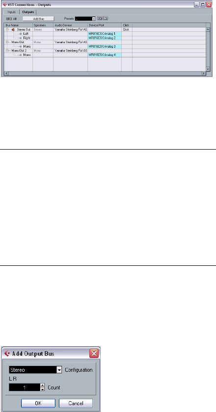
The VST Connections window
You add and set up busses in the VST Connections win-
dow, opened from the Devices menu.
This window contains the Inputs and Output tabs for view-
ing input busses and output busses.
Depending on which tab you have selected, the window
lists the current input or output busses, with the following
columns:
Adding a bus
1. Click the Inputs or Outputs tab depending on which
you want to add.
2. Click the Add Bus button.
A dialog appears.
3. Select the desired (channel) configuration.
You can add stereo and mono busses.
Column Description
Bus Name Lists the busses. You can select busses and rename
them by clicking on them in this column.
Speakers Indicates the speaker configuration (mono, stereo) of
each bus.
Audio Device This shows the currently selected ASIO driver.
Device Port When you have “opened” a bus (by clicking its + button
in the Bus Name column) this column shows which phys-
ical inputs/outputs on your audio hardware are used by
the bus.
Click You can route the click to a specific output bus.
12
VST Connections: Setting up input and output busses
•Alternatively you can right-click in the VST Connections
window and add a bus in the desired format directly from
the context menu.
The new bus appears with the ports visible.
4. Click in the Device Port column to select an input/out-
put port for a channel in the bus.
The pop-up menu that appears lists the ports with the names you have as-
signed in the Device Setup dialog. Repeat this for all channels in the bus.
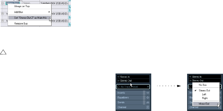
Setting the Main Mix bus (the default output bus)
The Main Mix is the output bus that each new channel in
the mixer will be assigned to when it is created.
Any of the output busses in the VST Connections window
can be the default output bus. By right-clicking on the
name of an output bus, you can set this bus as the Main
Mix bus.
Setting the default output bus in the VST Connections window.
When creating new audio, group or FX channels in the
mixer, they will automatically be routed to the default bus.
Presets
On the Inputs and Outputs tabs, you will find a Presets
menu. Here you can find three different types of presets:
•A number of standard bus configurations.
•Automatically created presets tailored to your specific
hardware configuration.
On each startup, Cubase AI will analyze the physical inputs and outputs
provided by your audio hardware and create a number of hardware-
dependent presets with the following possible configurations:
• one stereo bus
• various combinations of stereo and mono busses
• a number of mono busses
•You can also save your own setups as presets.
To store the current configuration as a preset, click the Store “+” button
and enter a name for the preset. You can then select the stored configu-
ration directly from the Presets pop-up menu at any time. To remove a
stored preset, select it and click the “-” button.
Other bus operations
•To change the port assignment for a bus, you proceed
as when you added it: Make sure the channels are visible
(by clicking the “+” button next to the bus, or by clicking
the “+ All” button at the top of the window) and click in the
Device Port column to select ports.
•To remove a bus you do not need, select it in the list,
right-click and select “Remove Bus” from the pop-up
menu, or press [Backspace].
Using the busses
This section describes briefly how to use the input and out-
put busses you have created. For details refer to the chap-
ters “Recording” on page 48 and “The mixer” on page 69.
Routing
When you play back an audio track (or any other audio-re-
lated channel in the mixer), you route it to an output bus. In
the same way, when you record on an audio track you se-
lect from which input bus the audio should be sent.
•You can select input and output busses in the Inspec-
tor, using the Input and Output Routing pop-up menus.
ÖFor audio-related channel types other than audio track
channels (i.e. VST Instrument channels, Group channels
and FX channels), only the Output Routing pop-up menu
is available.
!
The default bus is indicated by an orange colored
speaker icon next to its name in the VST Connec-
tions window.
13
VST Connections: Setting up input and output busses
When selecting an input bus for a track you can only se-
lect busses that correspond to the track’s channel config-
uration. Here are the details for input busses:
• Mono tracks can be routed to mono input busses or individual
channels within a stereo input bus.
• Stereo tracks can be routed to mono or stereo input busses.
For output busses any assignment is possible.
To disconnect input or output bus assignments, select
“No Bus” from the corresponding pop-up menu.
Viewing the busses in the mixer
ÖNote that only the output busses are available in the
mixer – not the input busses.
The available output busses are represented as output
channel strips in the mixer (shown in a separate pane to
the right). You can show or hide output channels by click-
ing the corresponding button in the mixer common panel:
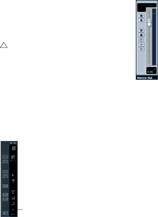
Output channels
The output channels are shown to the right in the mixer.
Here you can do the following:
•Adjust the output level for the busses with the faders.
•Open the Channel Settings window to add effects or EQ.
These will affect the whole bus. Examples of effects you may want to add
here include compressors, limiters and dithering, see the chapter “Audio
effects” on page 85.
About monitoring
The Main Mix bus (the default output bus) is used for mon-
itoring (see “Setting the Main Mix bus (the default output
bus)” on page 12).
You can adjust the monitoring level in the Mixer.
!
Assignments that will lead to feedback are not avail-
able in the pop-up menu. This is also indicated by a
one-way symbol.
Hide Output Channels
3
The Project window
15
The Project window
Background
The Project window is the main window in Cubase AI. This
provides you with an overview of the project, allowing you
to navigate and perform large scale editing. Each project
has one Project window.
About tracks
The Project window is divided vertically into tracks, with a
timeline running horizontally from left to right. The follow-
ing track types are available:
About parts and events
The tracks in the Project window contain parts and/or
events. Events are the basic building blocks in Cubase AI.
Different event types are handled differently in the Project
window:
• Video events and automation events (curve points) are always
viewed and rearranged directly in the Project window.
• MIDI events can always be found in MIDI parts, which are con-
tainers for one or more MIDI events. MIDI parts are rearranged
and manipulated in the Project window. To edit the individual
MIDI events in a part, you have to open the part in a MIDI edi-
tor (see “The MIDI editors” on page 181).
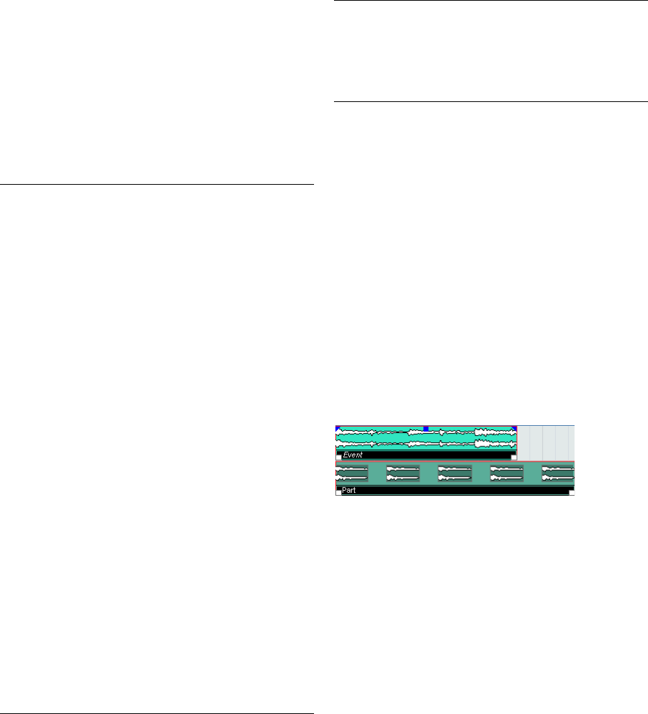
• Audio events can be displayed and edited directly in the
Project window, but you can also work with audio parts con-
taining several events. This is useful if you have a number of
events which you want to treat as one unit in the project. Au-
dio parts also contain information about the time position in
the project.
An audio event and an audio part
Audio handling
When you work with audio files, it is crucial to understand
how audio is handled in Cubase AI:
When you edit or process audio in the Project window,
you always work with an audio clip that is automatically
created on import or during recording. This audio clip re-
fers to an audio file on the hard disk that itself remains un-
touched. This means, that audio editing and processing is
“non-destructive”, in the sense that you can always undo
changes or revert to the original versions.
Track type Description
Audio For recording and playing back audio events and audio
parts. Each audio track has a corresponding audio chan-
nel in the mixer.
An audio track can have an automation track for automat-
ing mixer channel parameters, effect settings, etc.
Folder Folder tracks function as containers for other tracks, mak-
ing it easier to organize and manage the track structure.
They also allow you to edit several tracks at the same time,
see “Folder tracks” on page 37.
FX Channel FX channel tracks are used for adding send effects. Each
FX channel can contain up to eight effect processors – by
routing effect sends from an audio channel to an FX chan-
nel, you send audio from the audio channel to the effect(s)
on the FX channel. Each FX channel has a corresponding
channel strip in the mixer – in essence an effect return
channel, see the chapter “Audio effects” on page 85.
All FX channel tracks are automatically placed in a special
FX channel folder in the Track list, for easy management.
An FX channel can also have an automation track for au-
tomating mixer channel parameters, effect settings, etc.
Group
Channel By routing several audio channels to a Group channel,
you can submix them, apply the same effects to them,
etc. (see “Using group channels” on page 80).
A Group channel track contains no events as such, but
displays settings and automation curves for the corre-
sponding Group channel. Each Group channel track has
a corresponding channel strip in the mixer. In the Project
window, Group channels are organized as tracks in a
special Group Tracks folder.
Instrument This allows you to create a track for a dedicated instru-
ment, making e.g. VST instrument handling easier and
more intuitive. Instrument tracks have a corresponding
channel strip in the mixer. Each instrument track can have
an automation track in the Project window. However, Vol-
ume and Pan are automated from within the mixer. For
more information on instrument tracks, see the chapter
“VST Instruments and Instrument tracks” on page 99.
MIDI For recording and playing back MIDI parts. Each MIDI
track has a corresponding MIDI channel strip in the mixer.
A MIDI track can have an automation track for automating
mixer channel parameters, etc.
Marker The Marker track displays markers which can be moved
and renamed directly in the Project window (see “Mark-
ers” on page 38). A project can have only one marker
track.
Video For playing back video events. A project can have only
one video track.
Track type Description
16
The Project window
An audio clip does not necessarily refer to just one origi-
nal audio file! If you apply e.g. some processing to a spe-
cific section of an audio clip, this will create a new audio
file containing only this section. The processing will then
be applied to the new audio file only, leaving the original
audio file unchanged. Finally, the audio clip is automati-
cally adjusted, so that it refers both to the original file and
to the new, processed file. During playback, the program
will switch between the original file and the processed file
at the correct positions. You will hear this as a single re-
cording, with processing applied to one section only. This
feature makes it possible to undo processing at a later
stage, and to apply different processing to different audio
clips that refer to the same original file.
An audio event is the object that you place on a time po-
sition in Cubase AI. If you make copies of an audio event
and move them to different positions in the project, they
will still all refer to the same audio clip. Furthermore, each
audio event has an Offset value and a Length value. These
determine at which positions in the clip the event will start
and end, i.e. which section of the audio clip will be played
back by the audio event. For example, if you resize the au-
dio event, you will just change its start and/or end position
in the audio clip – the clip itself will not be affected.
ÖIf you want to use one audio file in different contexts,
or if you want to create several loops from one audio file,
you should convert the corresponding regions of the au-
dio clip to events and bounce them into separate audio
files. This is necessary since different events that refer to
the same clip access the same clip information.
17
The Project window
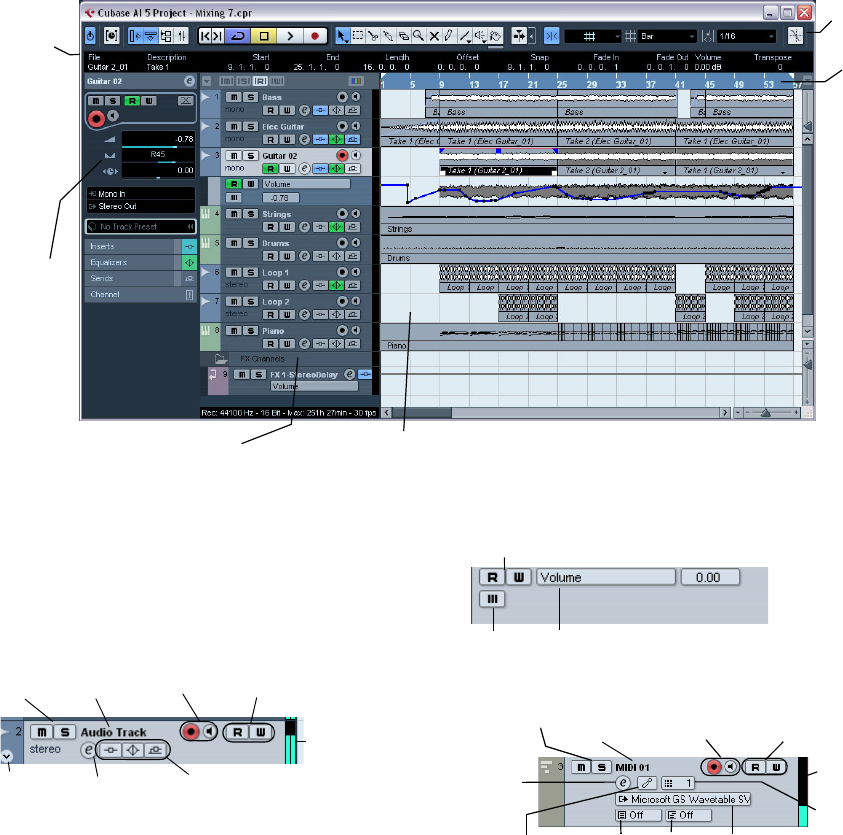
Window Overview
The Track list
The Track list displays all the tracks used in a project. It
contains name fields and settings for the tracks. Different
track types have different controls in the Track list. To see
all the controls you may have to resize the track in the Track
list (see “Resizing tracks in the Track list” on page 23).
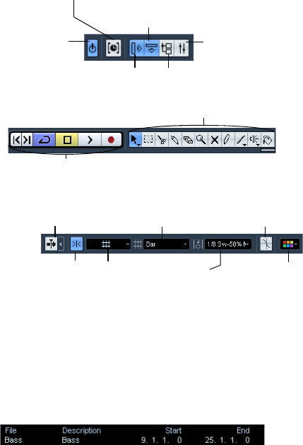
•The Track list area for an audio track:
•The Track list area for an automation track (opened by
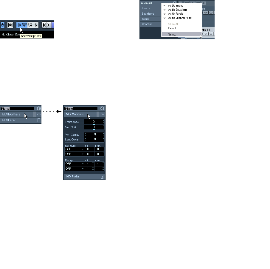
clicking the Show/Hide Automation button on a track):
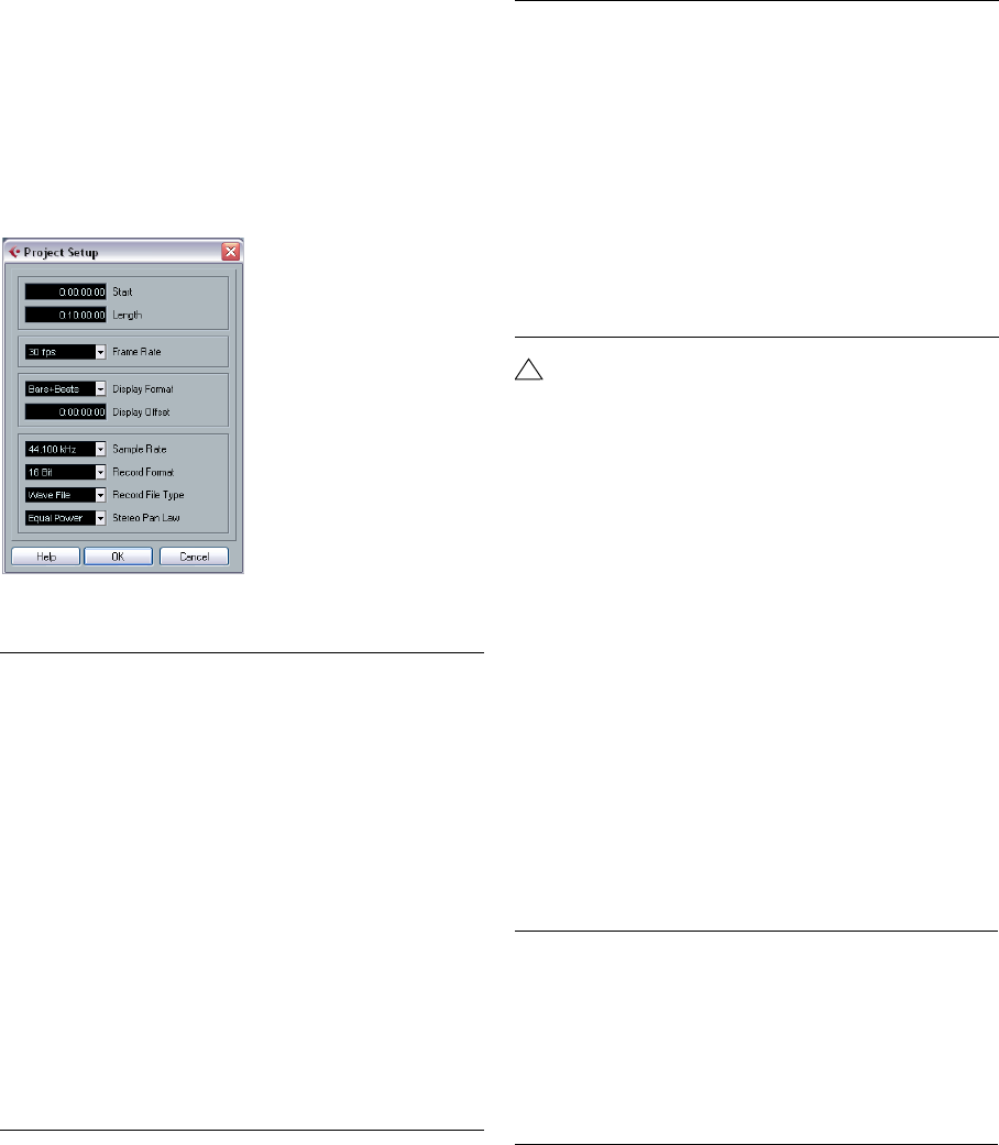
•The Track list area for a MIDI track:
Inspector
Ruler
Info line
Toolbar
The Track list with various track types The event display, showing audio parts and events, MIDI parts, automation, markers, etc.
Mute &
Solo Record Enable &
Monitor
Track
name
Show/hide
automation Indicate whether effect sends, EQ
or insert effects are activated for the
track. Click to bypass.
Automation
Read/Write
Track activity
indicator
Edit channel
settings
Automation Read/Write
Automation parameter (click to select parameter)
Mute
Record Enable &
Monitor
Track
name
MIDI Output
Bank Patch
MIDI channel
Drum map
Automation
Read/Write
Edit
channel
settings
Mute & Solo
Track activity
indicator
18
The Project window
The Inspector
The area to the left of the Track list is called the Inspector.
This shows additional controls and parameters for the track
you have selected in the Track list. If several tracks are se-
lected (see “Handling tracks” on page 26), the Inspector
shows the setting for the first (topmost) selected track.
To hide or show the Inspector, click the Inspector icon in
the toolbar.
The Inspector icon
•For most track classes, the Inspector is divided into a
number of sections, each containing different controls for
the track. You can hide or show sections by clicking on
their names.
Clicking the name for a hidden section brings it into view and hides the
other sections. [Ctrl]/[Command]-clicking the section name allows you
to hide or show a section without affecting the other sections. [Alt]/[Op-
tion]-clicking a section name shows or hides all sections in the Inspector.
•You can also use key commands to show different In-
spector sections.
These are set up in the Key Commands dialog, see “Setting up key com-
mands” on page 269.
ÖHiding a section does not affect its functionality.
For example, if you have set up a track parameter or activated an effect,
your settings will still be active even if you hide the respective Inspector
section.
Which sections are available in the Inspector depends on
the selected track.
ÖPlease note that not all Inspector tabs are shown by
default. You can show/hide Inspector sections by right-
clicking on an Inspector tab and activating/deactivating
the desired option(s).
Make sure you right-click on an inspector tab and not on the empty area
below the Inspector, as this will open the Quick context menu instead.
The Inspector Setup context menu
Inspector sections
The Inspector contains the controls that can be found on
the Track list, plus some additional buttons and parame-
ters. In the table below, these additional settings and the
different sections are listed. Which sections are available
for which track type is described in the following sections.
Parameter Description
Auto Fades
Settings
button
Opens a dialog in which you can make separate Auto
Fade settings for the audio track, see “Making Auto Fade
settings for a separate track” on page 68.
Edit Channel
settings Opens the Channel Settings window for the track, allow-
ing you to view and adjust effect and EQ settings, etc.,
see “Using Channel Settings” on page 76.
Volume Use this to adjust the level for the track. Changing this
setting will move the track’s fader in the mixer window,
and vice versa. See “Setting volume in the mixer” on page
74 to learn more about setting levels.
Pan Use this to adjust the panning of the track. As with the
Volume setting, this corresponds to the Pan setting in the
mixer.
Delay This adjusts the playback timing of the audio track. Positive
values delay the playback while negative values cause the
track to play earlier. The values are set in milliseconds.
Input Routing This lets you specify which Input bus or MIDI input the
track should use. See “Setting up busses” on page 10
for information about Input busses.
Output
Routing Here you decide to which output the track should be
routed. For audio tracks you select an output bus (see
“Setting up busses” on page 10) or Group channel, for
MIDI tracks you select a MIDI output and for Instrument
tracks, you select the Instrument to which it is routed.
Inserts section Allows you to add insert effects to the track, see the
chapters “Audio effects” on page 85 and “MIDI realtime
parameters” on page 166. The Edit button at the top of
the section opens the control panels for the added insert
effects.

19
The Project window
Audio tracks
For audio tracks, all settings and sections listed above are
available.
Instrument tracks
As explained in the chapter “VST Instruments and Instru-
ment tracks” on page 99, the Inspector for an Instrument
track shows some of the sections you would find for VST
Instrument channels and MIDI tracks.
MIDI tracks
When a MIDI track is selected, the Inspector contains a
number of additional sections and parameters, affecting the
MIDI events in realtime (e.g. on playback). Which sections
are available for MIDI tracks is described in the chapter
“MIDI realtime parameters” on page 166.
Folder tracks
When a folder track is selected, the Inspector shows the
folder and its underlying tracks, much like a folder struc-
ture in the Windows Explorer or Mac OS X Finder.
ÖYou can click one of the tracks shown under the folder
in the Inspector to have the Inspector show the settings
for that track. This way, you don’t have to “open” a folder
track to make settings for tracks within it.
FX channel tracks
When an FX channel track is selected, the following con-
trols and sections are available:
• Edit button
• Volume control
• Pan control
• Output Routing pop-up menu
• Inserts section
• Equalizers section
• Sends section
• Channel section
FX channel tracks are automatically placed in a special
folder, for easier management. When this folder track is
selected, the Inspector shows the folder and the FX chan-
nels it contains. You can click one of the FX channels
shown in the folder to have the Inspector show the set-
tings for that FX channel – this way you don’t have to
“open” a folder track to access the settings for the FX
channels in it.
Group channel tracks
When a Group channel track is selected, the following
controls and sections are available:
• Edit button
• Volume control
•Pan control
• Output Routing pop-up menu
• Inserts section
• Equalizers section
• Sends section
• Channel section
Just like FX channel tracks, all Group channel tracks are
placed in a separate folder – when this is selected, the In-
spector shows the folder and the Group channels it con-
tains. You can click one of the Group channels shown in
the folder to have the Inspector show the settings for that
Group channel – this way, you don’t have to “open” a folder
track to access the settings for the Group channels in it.
Marker tracks
When the marker track is selected, the Inspector shows
the marker list. For more information, see the section
“Markers” on page 38.
Video tracks
When a video track is selected, the Inspector contains a
Mute button for interrupting video playback.
Equalizers
section Lets you adjust the EQs for the track. You can have up to
four bands of EQ for each track, see “Making EQ set-
tings” on page 77. The Edit button at the top of the sec-
tion opens the Channel Settings window for the track.
Channel
section Shows a duplicate of the corresponding mixer channel
strip. The channel overview strip to the left lets you acti-
vate and deactivate insert effects, EQs and sends.
Parameter Description
20
The Project window
The toolbar
The toolbar contains tools and shortcuts for opening other
windows and various project settings and functions:
ÖIn addition to these, the toolbar can contain a number
of other tools and shortcuts, not visible by default. How to
set up the toolbar and specify which tools should be dis-
played or hidden is described in the section “Using the
Setup options” on page 262.
The info line
The info line shows information about the currently selected
event or part in the Project window. You can edit almost all
values on the info line using regular value editing. Length
and position values are displayed in the format currently se-
lected for the ruler (see “The ruler” on page 21).
•To hide or show the info line, click the Show Event Info
Line button on the toolbar.
The following elements can be selected for display and
editing on the info line:
• Audio events
•Audio parts
• MIDI parts
• Video events
•Markers
• Automation curve points
When several elements are selected
•If you have several elements selected, the info line will
show information about the first item in the selection. The
values will be shown in yellow to indicate that several ele-
ments are selected.
•If you edit a value on the info line, the value change is
applied to all selected elements, relatively to the current
values.
If you have two audio events selected and the first is one bar long and
the other two bars long, the info line shows the length of the first event
(one bar). If you now edit this value to 3 bars in the info line, the other
event will be resized by the same amount – and will thus be 4 bars long.
•If you press [Ctrl]/[Command] and edit on the info line,
the values will be absolute instead. In our example above,
both events would be resized to 3 bars. Note that [Ctrl]/
[Command] is the default modifier key for this – you can
change this in the Preferences (Editing–Tool Modifiers
page, under the Info Line category).
Editing Transpose and Velocity for MIDI parts
When one or several MIDI parts are selected, the info line
contains Transpose and Velocity fields.
•Adjusting the Transpose field transposes the selected
parts in semitone steps.
Note that this transposition doesn’t change the actual notes in the part –
it’s just a “play parameter”, affecting the notes on playback. The transpo-
sition you specify for a part on the info line is added to the transposition
set for the whole track.
•Adjusting the Velocity field shifts the velocity for the se-
lected parts – the value you specify is added to the veloc-
ities of the notes in the parts.
Again, this velocity shift only affects the notes on playback, and again,
the value you specify is added to the Vel.Shift. value set for the whole
MIDI track in the Inspector.
Active project
indicator
Show/hide Inspector
Show/hide info line
Open Mixer
Open Pool
Constrain delay compensation (see “Constrain Delay Compensation”
on page 106).
Project window tools
Transport controls
(Previous/Next Marker, Cycle, Stop, Play, and Record)
Snap on/off Snap mode
Grid pop-up
menu
Quantize
value Color pop-up
menu
Snap to Zero
Crossing
Autoscroll and Suspend
Autoscroll when Editing

21
The Project window
Getting on-the-fly info with the Arrow tool
If the option “Select Tool: Show Extra Info” is activated in
the Preferences (Editing–Tools page), a tooltip will be
shown for the Arrow tool, displaying information depending
on where you point it. For example, in the Project window
event display, the tool will show the current pointer position
and the name of the track and event you’re pointing at.
The ruler
The ruler at the top of the event display shows the timeline.
Initially, the Project window ruler uses the display format
specified in the Project Setup dialog (see “The Project
Setup dialog” on page 22), as do all other rulers and posi-
tion displays in the project. However, you can select an in-
dependent display format for the ruler by clicking the arrow
button to the right of it and selecting an option from the
pop-up menu (you can also bring up this pop-up menu by
right-clicking anywhere in the ruler).
•The selection you make here affects the ruler, the info
line and tooltip position values (which appear when you
drag an event in the Project window).
You can also select independent formats for other rulers and position
displays.
•To set the display format globally (for all windows), use
the primary display format pop-up on the Transport panel,
or hold down [Ctrl]/[Command] and select a display for-
mat in any ruler.
•If you use the “Timecode” option and the option “Show
Timecode Subframes” is activated in the Preferences
(Transport page), the frames will also display subframes.
There are 80 subframes per frame.
Operations
Creating a new project
You create a new project in the following way:
1. Select “New Project…” from the File menu.
The Project Assistant dialog appears, listing a number of recently
opened projects as well as the available templates. For detailed informa-
tion about this dialog, see “New Project” on page 254.
•To create the project based on an existing template (in-
cluding the corresponding tracks, events and settings),
select a template from the desired category.
•To create an empty project, select the Empty template
from the More category.
An emtpy project is also created if no template is selected in the cur-
rently shown category.
2. Select a location for saving the project.
•To create the project in the default location, select the
corresponding option. You can also enter a name for the
project folder in the “Project folder” field.
If you do not enter a name here, the project will reside in a folder named
“Untitled”. Naming is recommended at this stage, since having many fold-
ers titled “Untitled1”, “Untitled2”, etc. can be very confusing.
•To save your project in a different location, activate the
“Prompt for project location” button.
Click Continue to specify a location and set a project folder before creating
the project. New projects created like this are always untitled to begin with.
3. Depending on your choice above, click Create or
Continue.
If you selected the “Prompt for project location” option, a file dialog opens,
otherwise the new project is directly opened in the Project window.
Option Positions and lengths displayed as
Bars+Beats Bars, beats, sixteenth notes and ticks. By default there
are 120 ticks per sixteenth note.
Seconds Hours, minutes, seconds and milliseconds.
Timecode This format displays hours, minutes, seconds and frames.
The number of frames per second (fps) is set in the
Project Setup dialog (see “The Project Setup dialog” on
page 22). You can choose between 24, 25, 29.97 and
30fps or 29.97 and 30dfps (“drop frame”).
Samples Samples.
Time Linear When this is selected, the ruler will be linear relative to
time. This means that if there are tempo changes on the
tempo track, the distance between the bars will vary in
Bars+Beats mode.
Bars+Beats
Linear When this is selected, the ruler will be linear relative to
the meter position – bars and beats. This means that if
there are tempo changes on the tempo track, there still
will be the same distance between bars in Bars+Beats
mode. If the ruler is set to a time-based mode, the dis-
tance between seconds will vary depending on the
tempo changes.
22
The Project window
The Project Setup dialog
General settings for the project are made in the Project
Setup dialog. This is opened by selecting “Project
Setup…” from the Project menu.
ÖIf the “Run Setup on Create New Project” option is ac-
tivated in the Preferences dialog (General page), the Pro-
ject Setup dialog will open automatically when you create
a new project.
The following settings are available in the Project Setup
dialog:
Zoom and view options
Zooming in the Project window is done according to the
standard zoom techniques, with the following special notes:
•When you are using the Zoom tool (magnifying glass),
the result depends on the option “Zoom Tool Standard
Mode: Horizontal Zooming Only” in the Preferences (Edit-
ing–Tools page).
If this is activated and you drag a selection rectangle with the Zoom tool,
the window will only be zoomed horizontally (track height will not change).
If the option is off, the window will be zoomed both horizontally and verti-
cally.
•When using the vertical zoom sliders, the tracks are
scaled relatively.
In other words, if you have made any individual track height adjustments
(see below), the relative height differences are maintained.
You find the following options are available on the Zoom
submenu on the Edit menu:
Setting Description
Start The start time of the project. Allows you to have the project
start at another time than zero. Also used for setting the
sync start position when synchronizing Cubase AI to exter-
nal devices (see “Setting up Cubase AI for external sync to
timecode” on page 237). When you change this setting
you will be asked whether you want to keep the project
content at its timecode positions. “Yes” means that all
events will stay at their original timecode positions – i.e.
they will be moved in relation to the start of the project.
“No” means that all events keep their position relative to
the project start.
Length The length of the project.
Frame Rate Used when synchronizing Cubase AI with external equip-
ment. If Cubase AI is slave, this value is automatically set
to the frame rate of the incoming sync signal. If Cubase
AI is the master, this determines the frame rate of the sent
sync signal, see “Setting the Frame Rate” on page 235.
Display Format This is the global display format used for all rulers and
position displays in the program. However, you can make
independent display format selections for the individual
rulers and displays if you like.
For descriptions of the different display format options,
see “The ruler” on page 21.
Display Offset Offsets the time positions displayed in the ruler etc., al-
lowing you to compensate for the Start position setting.
Typically, if you synchronize Cubase AI to an external
source starting at a frame other than zero, you set the
Start position to this value. However, if you still want the
display in Cubase AI to start at zero, set the Display Off-
set to the same value.
Sample Rate The sample rate at which Cubase AI records and plays
audio.
Record
Format/
File Type
When you record audio in Cubase AI, the files that are
created will be of this resolution and file type, see “Se-
lecting a recording file format” on page 51.
Stereo Pan
Law Decides whether panning should use power compensa-
tion or not, see “About the “Stereo Pan Law” setting (au-
dio channels only)” on page 76.
!
While most Project Setup settings can be changed
at any time, you must select a sample rate once and
for all when starting with a new project! All audio files
must be of this sample rate to play back correctly.
Option Description
Zoom In Zooms in one step, centering on the project cursor.
Zoom Out Zooms out one step, centering on the project cursor.
Zoom Full Zooms out so that the whole project is visible. “The
whole project” means the timeline from the project
start to the length set in the Project Setup dialog (see
above).
Zoom to
Selection Zooms in horizontally and vertically so that the current
selection fills the screen.
Setting Description
23
The Project window
•If the option “Zoom while Locating in Time Scale” is ac-
tivated in the Preferences (Transport page), you can also
zoom by clicking in the main ruler and dragging up or
down with the mouse button pressed.
Drag up to zoom out; drag down to zoom in.
•You can zoom the contents of parts and events vertically,
using the waveform zoom slider in the top right corner of
the event display.
This is useful when viewing quiet audio passages.
•If you activate the option Quick Zoom in the Prefer-
ences (Editing page), the contents of parts and events will
not be continuously redrawn when you zoom manually.
Instead, the contents are redrawn once you have stopped changing the
zoom – activate this if screen redraws are slow on your system.
Resizing tracks in the Track list
•You can change the height of an individual track by
clicking on its lower border in the Track list and dragging
up or down.
To change the height of all tracks simultaneously, hold down [Ctrl]/
[Command] and resize one of the tracks in this way. If “Snap Track
Heights” is activated on the Track scale pop-up (see below), the track
height will change in fixed increments when you resize it.
•You can also change the width of the Track list area, by
dragging the border between the Track list and the event
display.
•By default, the controls shown for tracks in the Track list
will adapt to the track size. This means that when resizing
a track’s height or width the controls will be placed where
they best “fit in”.
If you prefer to have the controls in fixed positions, you can deactivate the
option “Wrap Controls” in the Track Controls settings dialog (see “Cus-
tomizing track controls” on page 263).
•You can decide for each track type which controls
should be shown in the Track list – see “Customizing
track controls” on page 263.
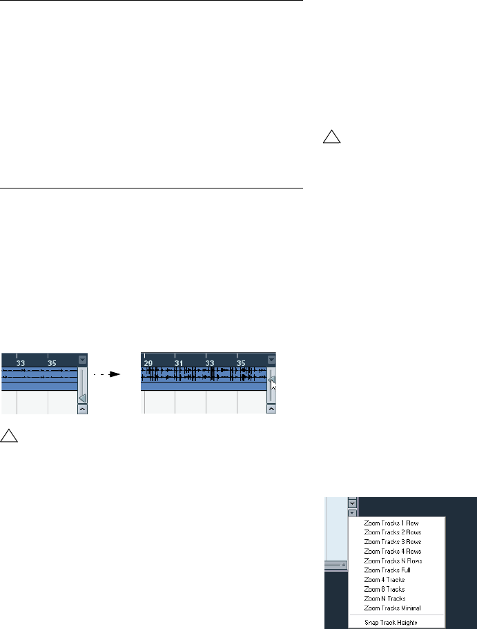
•You can use the Track scale pop-up (opened by clicking
the arrow button above the vertical zoom control) to set the
number of tracks to view in the current Project window.
The track height will be adjusted to show only the number of tracks spec-
ified on the pop-up menu. By selecting “Zoom N Tracks” from the pop-
up you can manually set the number of tracks to fit in the current Project
window.
Zoom to Selec-
tion (Horiz) Zooms in horizontally so that the current selection fills
the screen.
Zoom to Event This option is available only in the Sample Editor (see
“Zooming” on page 128).
Zoom In Vertically Zooms in one step vertically.
Zoom Out
Vertically Zooms out one step vertically.
Zoom In Tracks Zooms in on the selected track(s) one step vertically.
Zoom Out Tracks Zooms out the selected track(s) one step vertically.
Zoom Selected
Tracks This zooms in vertically on the selected track(s) and
minimizes the height of all other tracks.
!
To get an approximate reading on the level of the au-
dio events by viewing the waveforms, make sure this
slider is all the way down. Otherwise, zoomed wave-
forms may be mistaken for clipped audio.
Option Description
!
This behavior is different when “Enlarge Selected
Track” is activated on the Edit menu (see below).
24
The Project window
The Enlarge Selected Track option
When this option is activated on the Edit menu (or in the
Preferences, Editing–Project & Mixer page), the selected
track is enlarged automatically. This is useful if you are
stepping through the tracks in the Track list, to check or
edit the settings. The tracks will revert to the size they had
before when they are deselected. You can adjust the size
directly in the Track list if the default enlargement factor
does not suit you.
While this is the program behavior you will want in most
cases, it may be a disadvantage when changing the track
height you started out with for one or more tracks (i.e. their
“original” height, before “Enlarge Selected Track” was ac-
tivated). As soon as you try to resize a track, it is selected
and automatically enlarged. Instead of turning off “Enlarge
Selected Track”, resizing the desired track(s) and the acti-
vating “Enlarge Selected Track” again, you can resize a
track in the Track list without selecting it.
Proceed as follows:
1. Move the mouse pointer over the lower border of the
(unselected) track you want to resize.
The mouse pointer turns into a divider symbol.
2. Hold down [Alt]/[Option] and drag the lower border of
the track until it reaches the desired height.
Now, when you select this track, (and “Enlarge Selected Track” is acti-
vated), it will be enlarged. It will revert to the changed size, when you se-
lect a different track.
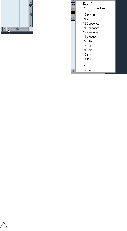
Zoom presets and Cycle markers
The pop-up menu to the left of the horizontal zoom control
allows you to select, create and organize zoom presets.
These are useful if you want to toggle between different
zoom settings (e.g. one where the whole project is dis-
played in the project window and another with a high zoom
factor for detailed editing). With this pop-up menu, you can
also zoom in on the area between cycle markers in the
project.
The upper part of the menu lists the zoom presets:
•To store the current zoom setting as a preset, select
Add from the pop-up menu.
A dialog appears, allowing you to type in a name for the preset.
•To select and apply a preset, select it from the pop-up
menu.
•The “Zoom Full” preset is always available. Selecting
this option zooms out so that the whole project is visible.
“The whole project” means the timeline from the project
start to the length set in the Project Setup dialog (see
“The Project Setup dialog” on page 22).
•If you want to delete a preset, select “Organize…” from
the pop-up menu.
In the dialog that appears, select the preset in the list and click the De-
lete button. The preset is removed from the list.
•If you want to rename a preset, select “Organize…”
from the pop-up menu.
In the dialog that appears, select the desired preset in the list and click
the Rename button. A second dialog opens, allowing you to type in a
new name for the preset. Click OK to close the dialogs.
The middle part of the pop-up lists any cycle markers you
have added in the project:
•If you select a cycle marker from this menu, the event
display is zoomed in to encompass the marker area (see
“Markers” on page 38).
!
Zoom presets are global for all projects, i.e. they are
available in all projects you open or create.
Click here…
…to open the context
menu.
25
The Project window
•You cannot edit the cycle markers in this pop-up menu.
For information on editing markers, see “Editing markers in
the Marker window” on page 38.
Adjusting how parts and events are shown
The Preferences on the File menu (the Cubase AI menu,
under Mac OS X) contains several settings for customiz-
ing the display in the Project window.
The Event Display page contains common settings for all
track types:
The Event Display–Audio page contains settings for audio
events:
The Event Display–MIDI page contains settings for MIDI
parts:
The Event Display–Video page contains settings for video
events:
!
Only the cycle markers you create in the current
project are available on the menu.
Option Description
Colorize Event
Background Determines whether the backgrounds or “contents”
(waveforms, etc.) of parts and events will be colorized,
see “Handling tracks” on page 26.
Show Event
Names Determines whether the names of parts and events
should be shown in the Project window.
Transparent
Events When this is activated, events and parts will be transpar-
ent, showing the waveforms and MIDI events only.
Show Data on
Small Track
Heights
If this is activated, the contents of events and parts will be
shown, even if the height of a track is very small.
Option Description
Interpolate
Audio Images If the option is deactivated, single sample values are
drawn as “steps”. If the option is activated they are inter-
polated to form “curves”.
Wave Image
Style Determines whether audio waveforms should be dis-
played as solid images, frames or “inverted” images
(solid+frame). This selection affects all waveform images
in the Project window, Sample Editor and Audio Part Ed-
itor.
Note that the “Framed” and “Solid and Framed” styles
are more demanding for the computer. If the system feels
slower in these modes, please switch back to “Solid”
wave image style.
Show Event
Volume Curves
Always
If this is activated the “volume curves” created with the
volume and fade handles are always shown – if not, the
curves are only shown for selected events.
Fade Handles
always on top When this option is activated, the fade handles stay at
the top of the event, and vertical help lines indicate the
exact end or start points of fades.
Thick Fade
Lines If this option is activated, the fade lines and volume
curves are thicker, increasing their visibility.
Show
Waveforms Determines whether audio waveforms should be shown
at all.
Background
Color
Modulation
When this is activated, the backgrounds of audio wave-
forms are displayed in a different way, reflecting the
waveform dynamics. This is especially useful to get an
overview when working with small track heights.
Option Description
Default Edit
Action Determines which editor should be opened when you
double-click a MIDI part or select it and press [Ctrl]/
[Command]-[E]: the Key, List, Drum or Score Editor.
Note that this setting is overridden for tracks with drum
maps if the option “Edit as Drums when Drum Map is as-
signed” (see below) is activated.
Part Data Mode Determines if and how events in MIDI parts should be
shown in the Project window: as score notes, as drum
notes or as lines. If “No Data” is selected, events will not
be shown at all. Note that this setting is overridden for
tracks with drum maps if the option “Edit as Drums when
Drum Map is assigned” (see below) is activated.
Show
Controllers Governs whether non-note events (controllers, etc.)
should be shown in MIDI parts in the Project window.
Edit as Drums
when Drum
Map is
assigned
If this is activated, parts on MIDI tracks with drum maps
assigned will be shown with drum note symbols in the
Project window. Also, the parts will automatically open in
the Drum Editor when double-clicked (overriding the De-
fault Edit Action setting above).
Note Name
Style Determines how MIDI note names (pitches) should be
displayed in editors, etc.
Option Description
Show Video
Thumbnails When this is activated, thumbnail frames of the video
contents are shown on the Video track.
Video Cache
Size This determines how much memory is available for video
thumbnails. If you have long video clips and/or work with
a large zoom factor (so that a lot of frames are shown in
the thumbnails), you may have to raise this value.
Option Description
26
The Project window
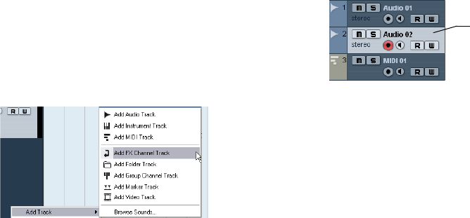
Handling tracks
To add a track to the project, select “Add Track” from the
Project menu and select a track type from the submenu
that appears. The new track is added below the currently
selected track in the Track list.
•The items on the “Add Track” submenu are also avail-
able on the context menu.
This is accessed by right-clicking in the Track list.
•If you select Audio, MIDI, Group Channel or Instrument
from the Add Track submenu, a dialog opens, allowing
you to insert several tracks in one go.
Just enter the desired number of tracks in the value field.
•For audio and group channel tracks, the channel config-
uration – mono or stereo – can be set in the Configuration
pop-up.
•The Browse Sounds option in the Add Track dialog is
described in the chapter “Working with Track Presets” on
page 155.
•In the Preferences (Editing–Project & Mixer page), you
can find the option “Auto Track Color Mode”.
This offers you several options for automatically assigning colors to
tracks that are added to the project.
Once you have created tracks, you can manipulate and re-
arrange them in various ways:
•To rename a track, double-click in the name field and
type in a new name.
If you hold down any modifier key when pressing [Return] to close the
name field, all events on the track will get the name you entered.
•To select a track, click on it in the Track list.
A selected track is indicated by a light gray color in the Track list.
It is possible to select several tracks by pressing [Ctrl]/[Command] and
clicking on them. [Shift]-click to select a continuous range of tracks.
•To move a track, click and drag it up or down in the list.
•To duplicate a track, complete with all contents and
channel settings, right-click in the Track list and select
“Duplicate tracks” from the context menu, or select “Dupli-
cate tracks” from the Project menu.
The duplicated track will appear below the original track.
•You can select a default color for a track by activating
“Show Track Colors” above the Track list and selecting a
color from the Color pop-up menu on the toolbar. This color
will be used for all events on the track and will also be
shown in the Mixer. You can override the default track color
for individual events and parts by using the Color tool or the
Color Selector pop-up menu. For more information, see
“Applying track and event colors” on page 265.
The option “Colorize Event Background” in the Preferences dialog
(Event Display page) determines whether the backgrounds or waveforms
of events will be colorized.
•To remove a track, right-click on it in the Track list and
select “Remove Selected Tracks” from the context menu.
You can also remove multiple selected tracks, by selecting “Remove Se-
lected Tracks” either from the context menu or from the Project menu.
•To change the track height of an individual track, click
on its lower border in the Track list and drag up or down,
see “Resizing tracks in the Track list” on page 23.
ÖNote that you can also automatically enlarge the se-
lected track, see “The Enlarge Selected Track option” on
page 24.
This track is selected.
27
The Project window
Disabling audio tracks
Audio tracks can be disabled by selecting “Disable Track”
from the Track list context menu. Disabling a track is simi-
lar to muting it (see “Muting events” on page 33), since a
disabled track will not be played back. However, disabling
a track not only “zeroes” the output volume from the track,
but actually shuts down all disk activity for it. See “About
track disable/enable” on page 45 for more information.
Adding events to a track
There are a number of ways to add events to a track:
•By recording (see “Basic recording methods” on page
49).
•By dragging files and dropping them on the track at the
desired position.
You can create events by dragging and dropping from the
following locations:
•The desktop
•The Pool
• The “Find media” dialog
• The Project window of another open project
• The Audio Part Editor of any open project
• The Sample Editor – press [Ctrl]/[Command] and drag to cre-
ate an event of the current selection.
While you drag the clip in the Project window, its position will be indi-
cated by a marker line and a numerical position box (see also “Using
drag and drop” on page 147).
•By selecting “Audio File…” or “Video File…” from the
Import submenu on the File menu.
This opens a file dialog, allowing you to locate the file you wish to import.
When you import a file this way, a clip is created for the file and an event
that plays the whole clip is inserted on the selected track, at the position
of the project cursor.
You can also import MIDI files by using the Import submenu, but this
works in a slightly different way (see “Exporting and importing standard
MIDI files” on page 259).
•By using Copy and Paste on the Edit menu.
This allows you to copy all kinds of events between projects. You can
also copy events within the project, e.g. from the Sample Editor.
•By drawing.
Some types of events (markers and automation events) can be drawn di-
rectly into the Project window. For audio and MIDI tracks, you can draw
parts (see “Creating parts” on page 28).
Audio file import options
When you are importing audio files there are a number of
options concerning how the files should be treated by Cu-
base AI:
• You can choose to copy the file into the audio folder of the
project and have the project make reference to the copied file
rather than the original file. This helps you keep your project
“self-contained”.
• Furthermore, you may want all files in the project to have the
same sample rate and sample size (resolution).
The Preferences dialog (Editing–Audio page) contains a
setting that lets you decide which options to use. Select
one of the following options on the “On Import Audio
Files” pop-up menu:
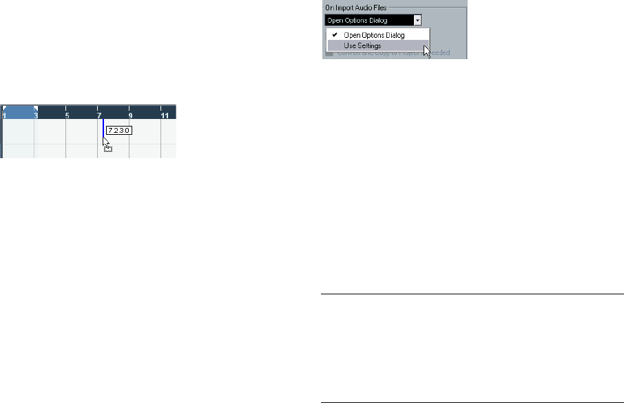
•Open Options Dialog
An Options dialog appears when you import, allowing you to select
whether you want to copy the files to the Audio folder and/or convert them
to the project settings. Please note the following:
– When importing a single file of a format other than the project settings,
you can specify which properties (sample rate and/or resolution) should be
changed.
– When importing multiple files at the same time, you can select to convert
the imported files automatically if necessary, i.e. if the sample rate is differ-
ent than the project’s or the resolution is lower than the project setting.
•Use Settings
No Options dialog will appear when you import. Instead, you can choose
to make any of the options below the pop-up the standard action(s). Ac-
tivate any number of the following options to have them performed auto-
matically each time you import audio files:
Option Description
Copy Files to
Working
Directory
If files are not already in the project’s audio folder they are
copied there before being imported.
Convert and
Copy to
Project If
Needed
If files are not already in the project’s audio folder they are
copied there before being imported. Furthermore, if the
files have a different sample rate or a lower resolution than
the project settings, they are automatically converted.
28
The Project window
Creating parts
Parts are containers for MIDI or audio events. If you record
MIDI, a MIDI part is automatically created, containing the
recorded events. You can also create empty audio or MIDI
parts and later add events to them.
There are two ways to do this:
•Draw a part on a MIDI or audio track with the Pencil tool.
You can also draw parts by pressing [Alt]/[Option] and using the Arrow
tool.
•Double-click with the Arrow tool on a MIDI or audio
track, between the left and right locator.
To add events to a MIDI part, you use the tools and func-
tions in a MIDI editor (see “The Key Editor – Overview” on
page 184). Adding events to audio parts is done in the
Audio Part Editor (see “Window overview” on page 139)
by pasting or by using drag and drop.
•You can also gather existing audio events into a part, by
using the “Events to Part” function on the Audio menu.
This creates an audio part containing all selected audio events on the
same track. To remove the part and make the events appear as indepen-
dent objects on the track again, select the part and use the “Dissolve
Part” function on the Audio menu.
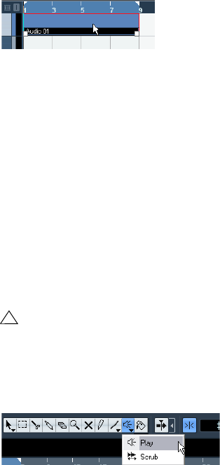
Auditioning audio parts and events
Audio parts and events can be auditioned in the Project
window with the Play tool:
1. Select the Play tool.
Note that the Play tool and the Scrub tool share the same tool button. If the
tool icon on the toolbar doesn’t show a speaker symbol, first click on the
icon to select it, then click again and select “Play” from the pop-up menu.
2. Click where you want playback to start, and keep the
mouse button pressed.
Only the track on which you click is played back, starting at the click po-
sition.
3. Release the mouse button to stop playback.
Scrubbing
The Scrub tool allows you to locate positions in the audio
by playing back, forwards or backwards, at any speed:
1. Select the Scrub tool.
Note that the Play tool and the Scrub tool share the same tool button. If the
tool icon on the toolbar doesn’t show a “scrub symbol”, first click on the
icon to select it, then click again and select “Scrub” from the pop-up menu.
2. Click at the desired position and keep the mouse but-
ton pressed.
The project cursor is moved to the position at which you click.
3. Drag to the left or right.
The project cursor follows the mouse pointer and the audio is played back.
The speed and pitch of the playback depend on how fast you move the
pointer.
You can adjust the responsiveness of the Scrub function
in the Preferences (Transport–Scrub page).
•Note that scrubbing can be quite a burden on your sys-
tem. To avoid playback problems, you will find the “CPU
Saving Scrub Mode” option in the Preferences (Transport–
Scrub page).
When you activate this option, scrubbing will be less demanding on the
processor. This can be very useful when scrubbing in a large project,
where the “normal” scrub behavior leads to processing overloads. When
“CPU Saving Scrub Mode” is activated, the effects are disabled for scrub-
bing and the resampling quality is lower.
Editing parts and events
This section describes techniques for editing in the Project
window. If not explicitly stated, all descriptions apply to both
events and parts, even though we use the term “event” for
convenience.
ÖWhen you are using the tools for editing, you can in
many cases get additional functions by pressing modifier
keys (e.g. pressing [Alt]/[Option] and dragging with the
Arrow tool creates a copy of the dragged event).
On the following pages, the default modifier keys are described – you
can customize these in the Preferences (Editing–Tool Modifiers page),
see “Setting up tool modifier keys” on page 271.
!
When auditioning, the Main Mix bus is used.

29
The Project window
Selecting events
Selecting events is done using any of the following
methods:
•Use the Arrow tool.
The standard selection techniques apply.
•Use the Select submenu on the Edit menu.
The options are:
•Select all events on a track by right-clicking on it in the
Track list and selecting “Select All Events” from the con-
text menu.
•You can also use the arrow keys on the computer key-
board to select the closest event to the left, right, above or
below.
If you press [Shift] and use the arrow keys, the current selection will be
kept, allowing you to select several events.
•If the option “Auto Select Events under Cursor” is acti-
vated in the Preferences (Editing page), all events on the
selected track(s) that are “touched” by the project cursor
are automatically selected.
This can be helpful when rearranging your project, since it allows you to
select whole sections (on all tracks) by selecting all tracks and moving
the project cursor.
•It is also possible to select ranges, regardless of the
event and track boundaries.
This is done using the Range Selection tool (see “Range editing” on
page 34).
•Note that in the Preferences (Editing page), you can
find the option “Use Up/Down Navigation Commands for
selecting Tracks only”.
By default, tracks are selected with the up/down arrow keys on the com-
puter keyboard. However, these are also used for selecting events (see
above) which can lead to confusing results in some cases. Since track
selection is a most vital operation in both editing and mixing, you have the
option to use the navigation controls for track selection only. The follow-
ing applies:
• When this option is deactivated and no event/part is selected
in the Project window, the up/down arrow keys on the com-
puter keyboard are used to step through the tracks in the
Track list – just as you would expect this to work.
• When this option is deactivated and an event/part is selected in
the Project window, the up/down arrow keys still step through
the tracks in the Track list – but on the currently selected track,
the first event/part will automatically be selected as well. If this is
not the desired behavior, you have to activate “Use Up/Down
Navigation Commands for selecting Tracks only”.
• When this option is activated, the up/down arrow keys are
only used to change the track selection – the current event/
part selection in the Project window will not be altered.
•Also in the Preferences (Editing–Tools page), you can
find the Cross Hair Cursor options section.
This allows you to display a cross hair cursor when working in the Project
window and editors, facilitating navigation and editing, especially when
arranging in large projects. You can set up the colors for the line and the
mask of the cross hair cursor, and define its width. The cross hair cursor
works as follows:
• When the Selection tool (or one of its subtools) is selected,
the cross hair cursor appears when you start moving/copying
a part/event, or when using the event trim handles.
• When the Pencil tool, the Scissors tool or any other tool that
makes use of this function is selected, the cross hair cursor ap-
pears as soon as you move the mouse over the event display.
• The cross hair cursor is only available for tools where such a
function is of any use. The Mute tool for example does not use
a cross hair cursor, as you have to click directly on an event to
mute it.
Option Description
All Selects all events in the Project window.
None Deselects all events.
In Loop Selects all events that are partly or wholly between
the left and right locator.
From Start to
Cursor Selects all events that begin to the left of the project
cursor.
From Cursor to
End Selects all events that end to the right of the project
cursor.
All on Selected
Tracks Selects all events on the selected track.
Select Event This is available in the Sample Editor (see “Window
overview” on page 126).
Left/Right Selec-
tion Side to Cursor These two functions are only used for range selection
editing (see “Creating a selection range” on page 34).
!
Note that these functions work differently when the
Range Selection tool is selected (see “Creating a
selection range” on page 34).
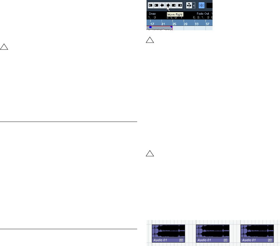
30
The Project window
Moving events
To move events in the Project window, use the following
methods:
•Click and drag to a new position.
All selected events will be moved, maintaining their relative positions. You
can only drag events to tracks of the same type. If Snap is activated, this
determines to which positions you can move the events (see “The Snap
function” on page 40).
Note also that you can restrict movement to be either horizontal or vertical
only, by holding down [Ctrl]/[Command] while dragging.
•Select the event and edit the Start position in the info
line.
•Use the “Move to” options on the Edit menu.
The following options are available:
•Use the Nudge buttons in the toolbar.
These move the selected events to the left or right. The amount of move-
ment depends on the selected display format (see “The Project Setup di-
alog” on page 22) and the value set on the Grid pop-up menu.
ÖThe Nudge buttons are not visible in the toolbar by de-
fault.
You can decide which items should be visible by right-clicking in the
toolbar and activating the corresponding option on the context menu.
See “The setup context menus” on page 262 for more information.
Duplicating events
Events can be duplicated in the following ways:
•Hold down [Alt]/[Option] and drag the event to a new
position.
If Snap is activated, this determines to which positions you can copy the
events (see “The Snap function” on page 40).
•Audio and MIDI parts can also be duplicated by press-
ing [Alt]/[Option]-[Shift] and dragging.
This creates a shared copy of the part. If you edit the contents of a
shared copy, all other shared copies of the same part are automatically
edited in the same way.
Shared copies are indicated by showing the name in italic text and an
icon in the right corner of the part.
!
You will note that there is a slightly delayed response
when you move an event by dragging. This helps you
avoid accidentally moving events when you click on
them in the Project window. You can adjust this de-
lay with the Drag Delay setting in the Preferences
(Editing page).
Option Description
Cursor Moves the selected event to the project cursor position. If
there are several selected events on the same track, the
first event will start at the cursor, and the following will be
lined up end-to-start after the first one.
Origin Moves the selected events to their original positions, i.e.
the positions at which they were originally recorded.
Front/Back This function doesn’t actually change the position of the
events, but moves the selected events to the front or
back, respectively. This is useful if you have overlapping
events, and want to see one that is partially obscured.
For audio events, this is an extra important feature, since
only the visible sections of events will be played back.
Moving an obscured audio event to front (or moving the
obscuring event to back) will allow you to hear the whole
event on playback (see also “Overlapping events” on
page 140).
Note that it is also possible to use the “To Front” function
on the event context menu for this.
!
When the Range Selection tool is used, the Nudge
buttons move the selection range (see “Moving and
duplicating” on page 36).
!
If you hold down [Ctrl]/[Command] as well, move-
ment direction is restricted to either horizontal or ver-
tical. That means if you drag an event vertically it
cannot be moved horizontally at the same time.
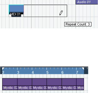
31
The Project window
Note:
•When you duplicate audio events, the copies are al-
ways shared. This means that shared copies of audio
events always refer to the same audio clip (see “Audio
processing” on page 118).
•You can convert a shared copy to a real copy by select-
ing “Convert to Real Copy” from the Edit menu. This cre-
ates a new version of the clip (that can be edited indepen-
dently) and adds this to the Pool. Note that no new files are
created by this operation – for that you need to use the
“Bounce Selection” function from the Audio menu.
•Selecting “Duplicate” from the Edit menu creates a
copy of the selected event and places it directly after the
original.
If several events are selected, all of these are copied “as one unit”, main-
taining the relative distance between the events.
•Selecting “Repeat…” from the Edit menu opens a dia-
log, allowing you to create a number of copies (regular or
shared) of the selected event(s).
This works just like the Duplicate function, but you can specify the num-
ber of copies.
•You can also perform the Repeat function by dragging:
Select the event(s) to repeat, press [Alt]/[Option], click the
handle in the lower right corner of the last selected event
and drag to the right.
The longer to the right you drag, the more copies are created (as shown
by the tooltip).
•Selecting “Fill Loop” from the Edit menu creates a num-
ber of copies starting at the left locator and ending at the
right locator.
The last copy is automatically shortened to end at the right locator position.
Using Cut, Copy and Paste
You can cut or copy selected events, and paste them in
again, using the functions on the Edit menu.
•When you paste an audio event, it is inserted on the se-
lected track, positioned so that its snap point is aligned
with the cursor position.
If the selected track is of the wrong type, the event will be inserted on its
original track. See “The Snap function” on page 40 for information about
the snap point.
•If you use the “Paste at Origin” function, the event is
pasted at its original position (the position from which you
cut or copied it).
Renaming events
By default, audio events show the name of their clip, but
you can enter a separate descriptive name for separate
events if you like. This is done by selecting the event and
typing in a new name in the “Description” field in the info
line.
•You can also give all events on a track the same name
as the track by changing the track name, holding down a
modifier key and pressing [Return].
See “Handling tracks” on page 26.
Splitting events
You can split events in the Project window in the following
ways:
•Click with the Scissors tool on the event you want to
split.
If Snap is activated, this determines the exact split position (see “The
Snap function” on page 40). You can also split events by pressing [Alt]/
[Option] and clicking with the Arrow tool.
•Select “Split at Cursor” from the Edit menu.
This splits the selected events at the position of the project cursor. If no
events are selected, all events (on all tracks) that are intersected by the
project cursor will be split.
•Select “Split Loop” from the Edit menu.
This splits events on all tracks at the left and right locator positions.
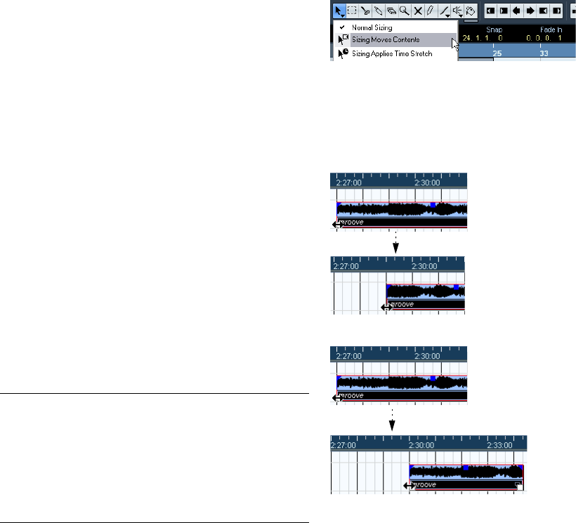
32
The Project window
ÖIf you split a MIDI part so that the split position inter-
sects one or several MIDI notes, the result depends on the
option “Split MIDI Events” in the Preferences (Editing–MIDI
page).
If the option is activated, the intersected notes will be split (creating new
notes at the beginning of the second part). If it is deactivated, the notes
will remain in the first part, but “stick out” after the end of the part.
Gluing events together
You can glue events together using the Glue Tube tool.
There are three possibilities:
•Clicking on an event with the Glue Tube tool glues it to-
gether with the next event on the track. The events do not
have to touch one another.
The result is a part containing the two events, with one exception: If you
first split an event and then glue the two sections together again (without
moving or editing them first), they become a single event again.
•You can select several events on the same track and
click on one of them with the Glue Tube tool.
A single part is created.
•When you hold down [Alt]/[Option] while clicking on an
event with the Glue Tube tool, this event will be glued to-
gether with all following events on this track.
You can change the default key command for this in the Preferences
(Editing–Tool Modifiers page).
Resizing events
Resizing events means to move their start or end positions
individually. In Cubase AI, there are three types of resizing:
To select one of the resizing modes, select the Arrow tool
and then click again on the Arrow tool icon on the toolbar.
This opens a pop-up menu from which you can select one
of the resizing mode options.
The icon on the toolbar will change, indicating the selected resizing
mode.
The actual resizing is done by clicking and dragging the
lower left or right corner of the event. If Snap is activated,
the Snap value determines the resulting length (see “The
Snap function” on page 40).
Normal sizing
Sizing moves contents.
•If several events are selected, all will be resized in the
same way.
•You can also resize events with the Scrub tool.
This works just the same as when resizing with the Arrow tool, but the
audio under the pointer is played back (scrubbed) while you drag.
Resizing type Description
Normal Sizing The contents of the event stay fixed, and the start or end
point of the event is moved to “reveal” more or less of the
contents.
Sizing Moves
Contents The contents follow the moved start or end of the event
(see the figure below).
Sizing Applies
Time Stretch The contents will be time stretched to fit the new event
length (see the separate section “Resizing events using
time stretch” on page 33).
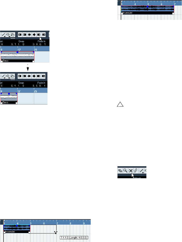
33
The Project window
•It is also possible to resize events by using the Trim but-
tons (located in the Nudge palette) on the toolbar.
This will move the start or end position of the selected Event(s) by the
amount set on the Grid pop-up menu. The sizing type currently selected
applies to this method too, with the exception of “Sizing Applies Time
Stretch” which is not possible with this method. You can also use key
commands for this (by default, press [Ctrl]/[Command] and use the left
and right arrow key).
ÖNote that the Nudge palette is not visible in the toolbar
by default. See “The setup context menus” on page 262 for
instructions on how to show and hide items in the toolbar.
ÖWhen resizing events, any automation data will not be
taken into account.
Resizing events using time stretch
If you want to resize a part and make its contents “fit” the
new size, you should use this option. Proceed as follows:
1. Click the Arrow icon on the toolbar and select the “Siz-
ing Applies Time Stretch” option from the pop-up menu.
2. Point close to the end point of the part you want to
stretch.
3. Click and drag left or right.
When you move the mouse, a tooltip shows the current mouse position
and length of the part. Note that the snap value applies, as with any part
operation.
4. Release the mouse button.
The part is “stretched” or “compressed” to fit the new length.
•For MIDI parts, this means that the note events are
stretched (moved and resized).
Controller data will be moved.
•For audio parts, this means that the events are moved,
and that the referenced audio files are time stretched to fit
the new length.
A dialog shows the progress of the time stretch operation.
Sliding the contents of an event or part
You can move the contents of an event or part without
changing its position in the Project window. By default,
this is done by pressing [Alt]/[Option]-[Shift], clicking in
the event or part and dragging to the left or right.
Muting events
To mute individual events in the Project window, proceed
as follows:
•To mute or unmute a single event, click on it with the
Mute tool.
•To mute or unmute several events, select them – either
by using the standard selection techniques, or by using
one of the options on the Select submenu on the Edit
menu – and click on one of the selected events with the
Mute tool.
All selected events will be muted.
•You can also click in an empty area with the Mute tool
and drag a selection rectangle around several events you
want to mute or unmute, and then click on one of them
with the Mute tool.
!
When sliding the contents of an audio event, you can-
not slide past the start or end of the actual audio clip.
If the event plays the whole clip, you cannot slide the
audio at all.
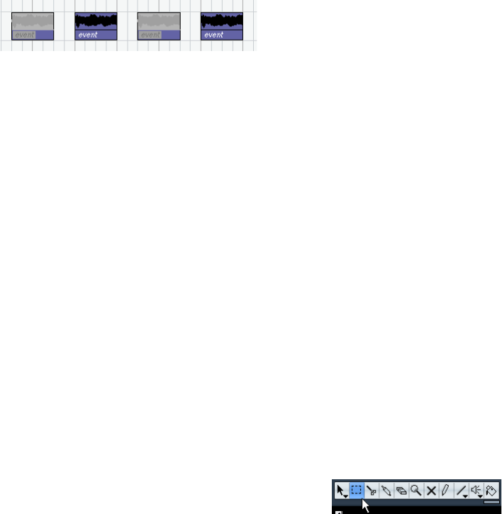
34
The Project window
•You can mute events by selecting them and selecting
“Mute” from the Edit menu.
Similarly, you can unmute the selected events by selecting “Unmute”
from the Edit menu.
•You can also change the mute status of selected events
on the info line.
Muted events can be edited as usual (with the exception
of adjusting fades), but are not played back.
Muted events are “grayed out”.
•You can also mute whole tracks by clicking the Mute
(“M”) button in the Track list, the Inspector or the mixer.
Clicking the Solo (“S”) button for a track mutes all other tracks. Note that
there are two modes for the track solo function:
If the option “Enable Solo on Selected Track” is activated in the Prefer-
ences (Editing–Project & Mixer page) and you have soloed a track, se-
lecting another track in the Track list will automatically solo that track
instead – the solo state “moves” with the track selection.
If the option isn’t activated, the track you solo stays soloed, regardless of
the selection.
Removing events
To remove an event from the Project window, use any of
the following methods:
•Click on the event with the Erase tool.
Note that if you press [Alt]/[Option] while you click, all following events
on the same track will be deleted, but not the event you clicked and all
events before it.
•Select the event(s) and press [Backspace], or select
“Delete” from the Edit menu.
Creating new files from events
An audio event plays a section of an audio clip, which in
turn refers to one or more audio files on the hard disk.
However, in some situations you may want to create a new
file that consists only of the section played by the event.
This is done with the function “Bounce Selection” on the
Audio menu:
1. Select one or several audio events.
2. Set up fade in, fade out and event volume (on the info
line or using the volume handle) as desired.
These settings will be applied to the new file. For details on fades and
event volume, see “Creating fades” on page 63.
3. Select “Bounce Selection” from the Audio menu.
You are asked whether you want to replace the selected event or not.
•If you click “Replace”, a new file is created, containing
only the audio in the original event. A clip for the new file is
added to the Pool, and the original event is replaced by a
new event playing the new clip.
•If you click “No”, a new file is created and a clip for the
new file is added to the Pool.
The original event is not replaced.
You can also apply the Bounce Selection function to an au-
dio part. In that case, the audio from all events in the part
will be combined into a single audio file. If you choose “Re-
place” when asked, the part will be replaced with a single
audio event playing a clip of the new file.
Range editing
Editing in the Project window isn’t necessarily restricted
to handling whole events and parts. You can also work
with selection ranges, which are independent from the
event/part and track boundaries.
Creating a selection range
To make a selection range, drag with the Range Selection
tool.
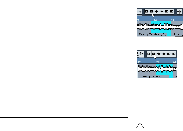
35
The Project window
When the Range Selection tool is selected, the Select
submenu on the Edit menu has the following items for
making selection ranges:
•Double-clicking on an event with the Range Selection
tool creates a selection range encompassing the event.
If you hold down [Shift] you can double-click several events in a row, and
the selection range will expand to encompass them all. Double-clicking a
second time on an event opens it for editing in the Sample Editor.
Adjusting the size of the selection range
You can adjust the size of a selection range in the follow-
ing ways:
•By dragging its edges.
The pointer takes the shape of a double arrow when you move it over an
edge of the selection range.
•By holding down [Shift] and clicking.
The closest selection range edge will be moved to the position at which
you clicked.
•By adjusting the selection range start or end position on
the info line.
•By using the Trim buttons on the toolbar.
The left Trim buttons will move the start of the selection range and the
right buttons will move the end. The edges will be moved by the amount
specified on the Grid pop-up.
Clicking this Trim button…
…will move the start of the selection range to the right by 1beat.
•By using the Nudge buttons on the toolbar.
These will move the whole selection range to the left or the right. The
amount of movement depends on the selected display format (see “The
Project Setup dialog” on page 22) and the value specified on the Grid
pop-up menu.
ÖThe Trim buttons and the Nudge buttons are located
in the Nudge palette, which is not visible in the toolbar by
default.
See “The setup context menus” on page 262 for instructions on how to
show and hide items in the toolbar.
Option Description
All Makes a selection that covers all tracks, from the start of
the project to the end (as defined by the Length setting
in the Project Setup dialog).
None Removes the current selection range.
In Loop Makes a selection between the left and right locator, on
all tracks.
From Start to
Cursor Makes a selection on all tracks, from the start of the
project to the project cursor.
From Cursor to
End Makes a selection on all tracks, from the project cursor
to the end of the project.
All on Selected
Tracks Only used for event selection (see “Selecting events” on
page 29).
Select Event This is available in the Sample Editor (see “Using the
Select menu” on page 130).
Left Selection
Side to Cursor Moves the left side of the current selection range to the
project cursor position.
Right Selection
Side to Cursor Moves the right side of the current selection range to
the project cursor position.
!
Note that the contents of the selection are not moved
– using the Nudge buttons is the same as adjusting
the start and end of the selection range at the same
time, by the same amount.
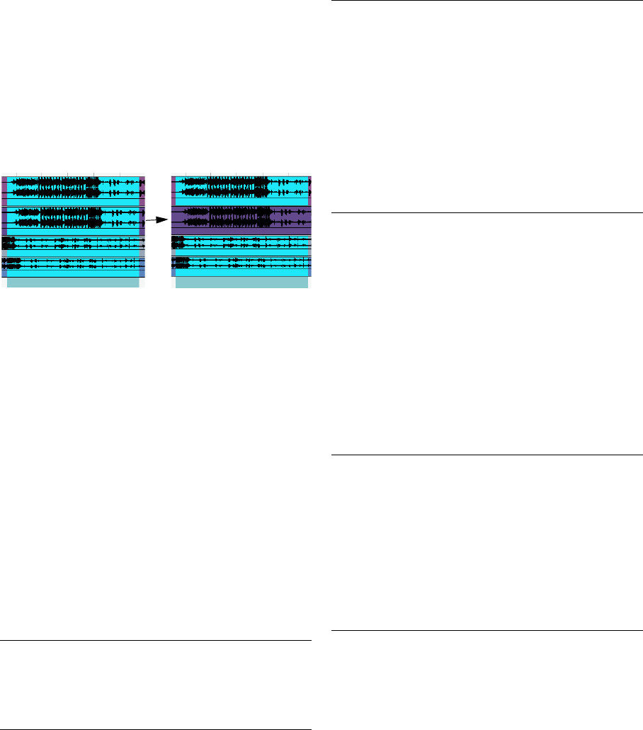
36
The Project window
Making selection ranges for several non-contiguous
tracks
You can create selection ranges that cover several tracks
by pressing [Alt]/[Option]-[Shift]. However, it is also pos-
sible to exclude tracks from a selection range:
1. Create a selection range from the first to the last de-
sired track.
2. Press [Alt]/[Option] and click in the selection range on
the tracks you want to exclude from the selection.
3. In the same manner, you can add a track to the selec-
tion range by [Alt]/[Option]-clicking in the selection range
area on the track.
Moving and duplicating
•To move a selection range, click and drag it to a new
position.
This will move the contents of the selection range to the new position. If
the range intersected events or parts, these will be split before moving,
so that only the sections within the selection range are affected.
•To duplicate a selection range, hold down [Alt]/[Option]
and drag.
You can also use the Duplicate, Repeat and Fill Loop functions, just as
when duplicating events (see “Duplicating events” on page 30).
Using Cut, Copy and Paste
When working with selection ranges, you can either use
Cut, Copy and Paste on the Edit menu, or use the func-
tions “Cut Time” and “Paste Time” on the Range submenu
on the Edit menu. These work differently to their related
functions on the Edit menu:
Deleting selection ranges
Again, you can either use “regular” Delete or “Delete Time”:
•If you use the Delete function on the Edit menu (or press
[Backspace]), the data within the selection range is re-
placed by empty track space.
Events to the right of the range keep their position.
•If you use “Delete Time” on the Edit menu’s Range sub-
menu, the selection range is removed and events to the
right are moved to the left to close up the gap.
Other functions
On the Range submenu on the Edit menu, you will find
three more range editing functions:
Function Description
Cut Cuts out the data in the selection range and moves it to
the clipboard. The selection range is replaced by empty
track space in the Project window, meaning that events
to the right of the range keep their positions.
Copy Copies the data in the selection range to the clipboard.
Paste Pastes the clipboard data at the start position and track
of the current selection. Existing events are not moved to
make room for the pasted data.
Paste at Origin Pastes the clipboard data back at its original position. Ex-
isting events are not moved to make room for the pasted
data.
Cut Time Cuts out the selection range and moves it to the clip-
board. Events to the right of the removed range are
moved to the left to fill out the gap.
Paste Time Pastes the clipboard data at the start position and track
of the current selection. Existing events are moved to
make room for the pasted data.
Paste Time at
Origin Pastes the clipboard data back at its original position. Ex-
isting events are moved to make room for the pasted data.
Function Description
Split Splits any events or parts that are intersected by the selec-
tion range, at the positions of the selection range edges.
Crop All events or parts that are partially within the selection
range are cropped, that is, sections outside the selection
range are removed. Events that are fully inside or outside
the selection range are not affected.
Insert Silence Inserts empty track space from the start of the selection
range. The length of the silence equals the length of the
selection range. Events to the right of the selection range
start are moved to the right to “make room”. Events that
are intersected by the selection range start are split, and
the right section is moved to the right.
Function Description
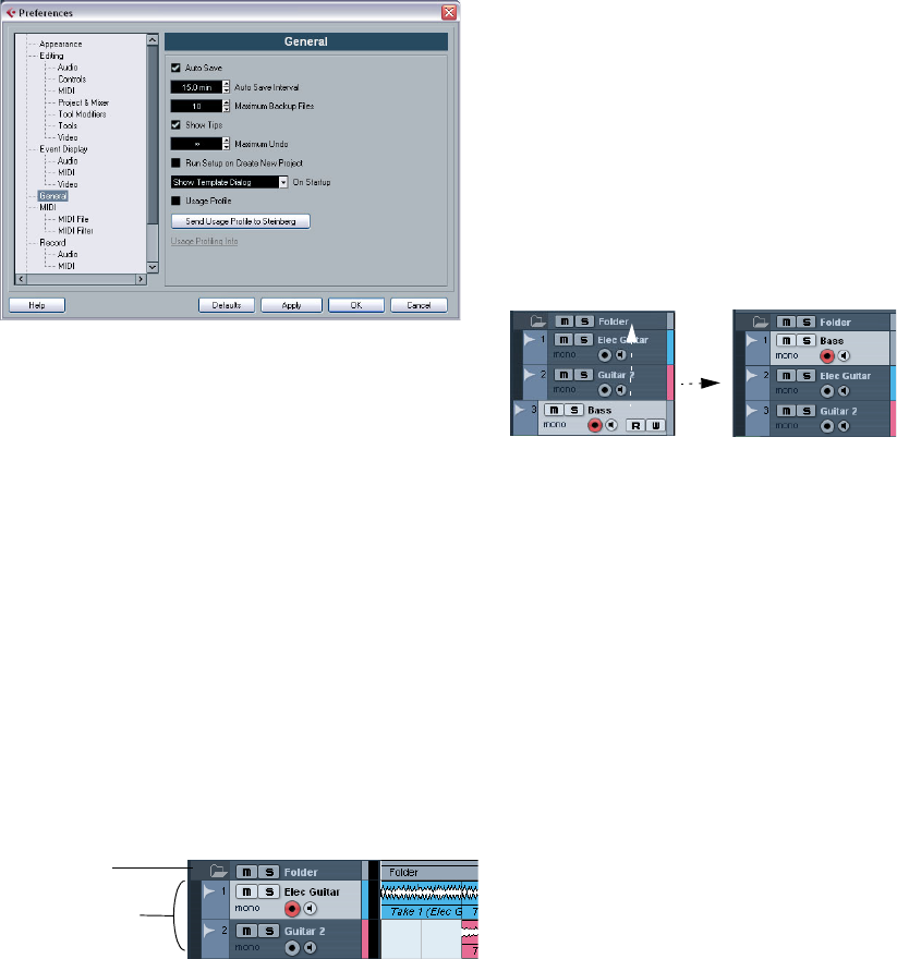
37
The Project window
The Preferences dialog
When you open the File menu (the Cubase AI menu on a
Mac) and select “Preferences…”, the Preferences dialog is
opened. This dialog provides a large number of options and
settings that control the global behavior of Cubase AI.
The dialog has a number of pages, each containing op-
tions and settings belonging to a particular topic.
•In the list on the left, click on one of the entries to open
the corresponding page.
•You can find detailed descriptions of all Preferences
options in the dialog help, opened by clicking the Help
button at the bottom left of the dialog.
Folder tracks
Moving tracks into a folder is a way to structure and orga-
nize tracks in the Project window. By grouping tracks in
folder tracks, you can solo and mute them in a quicker and
easier way and perform editing on several tracks as one
entity. Folder tracks can contain any type of track includ-
ing other folder tracks.
Handling folder tracks
•Creating a folder track
Select “Add Track” from the Project menu and select “Folder” from the
submenu that appears, or right-click in the Track list and select “Add
Folder Track” from the context menu to create a folder track.
•Moving tracks into a folder
In the Track list, click on a track that you want to move into a folder and
drag it onto a folder track. A green arrow pointing to a folder appears when
you drag the track onto the folder track in the list. The track is placed in the
folder track, and all parts and events on the track will be represented by a
corresponding folder part (see below). You can also create sub-folders by
moving one folder track into another. For example, you could have a folder
containing all the vocals in a project, and each vocal part could have a
folder containing all the takes for easier handling etc.
•Removing tracks from a folder
Drag a track out of the folder and release it in the Track list to remove it
from the folder.
•Hiding/showing tracks in a folder
Click on the “Expand/Collapse Folder” button (the folder icon) to hide or
show the tracks located in a folder. Hidden tracks are played back as
usual.
•Muting and soloing folder tracks
Click the Mute or Solo button on the folder track to mute or solo all
tracks in the folder as one unit.
Working with folder parts
A folder part is a graphic representation of events and
parts on the tracks in the folder. Folder parts indicate the
position and length of the events and parts, as well as on
which track they are (their vertical position). If part colors
are used, these are also shown in the folder part.
Any Project window editing you perform to a folder part
affects all the events and parts it contains. You can select
several folder parts if you like – this allows you to handle
and edit them together. The editing you can perform in-
cludes:
• Moving a folder part. This will move its contained events and
parts (possibly resulting in other folder parts, depending on
how the parts overlap).
A folder track
Tracks in the folder
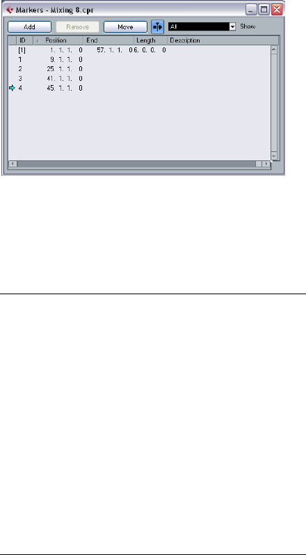
38
The Project window
• Using cut, copy and paste.
• Deleting a folder part. This will delete its contained events and
parts.
• Splitting a folder part with the Scissors tool.
• Gluing folder parts together with the Glue tube tool. This will
only work if the adjacent folder parts contain events or parts
on the same track.
• Resizing a folder part resizes the contained events and parts
according to the selected resizing method, see “Resizing
events” on page 32.
• Muting a folder part. This will mute its contained events and
parts.
Tracks inside a folder can be edited as one entity by per-
forming the editing directly on the folder part containing
the tracks. You can also edit individual tracks within the
folder by showing the contained tracks, selecting parts
and opening editors as usual.
Double-clicking a folder part opens the editors for the cor-
responding track classes present in the folder. The follow-
ing applies:
•All MIDI parts located on the tracks within the folder are
displayed as if they were on the same track, just like when
opening the Key Editor with several MIDI parts selected.
To be able to easily discern the different tracks in the editor, give each
track a different color in the Project window and use the “Part Colors”
option in the editor (see “Coloring notes and events” on page 188).
•If the folder contains tracks with audio events and/or au-
dio parts, the Sample and/or Audio Part Editors are opened
with each audio event and audio part in a separate window.
Markers
Markers are used to locate certain positions quickly. If you
often find yourself jumping to a specific position within a
project, you should insert a marker at this position. There
are two types of markers:
•Cycle markers allow you to store the start and end posi-
tions of a range.
On the Marker track they are shown as two markers bridged by a hori-
zontal line. They are ideal for setting sections of a song, for example “In-
tro”, “Verse”, and “Chorus”, this enables you to quickly navigate to the
song sections, and also to optionally repeat the section (by activating
Cycle on the Transport panel). Cycle markers can freely overlap.
•Standard markers store a specific position.
ÖThe left and right locators are handled separately –
see “The left and right locators” on page 45.
Editing markers in the Marker window
The Marker window lists the markers in the order in which
they occur in the project. To open the Marker window, se-
lect “Markers” from the Project menu, click the “Show”
button in the Marker section on the Transport panel or use
the key command (by default [Ctrl]/[Command]-[M]).
The Marker window is divided into six columns:
Click on a column heading to sort the marker list by that
column. The Marker columns can also be reordered by
dragging and dropping the column headers.
Column Description
Locate (left-
most column) If you click in this column the project cursor will be moved
to the corresponding marker position. A blue arrow indi-
cates the marker at the project cursor position (or the
closest marker before the project cursor).
ID In this column you can edit marker ID numbers. Each time
you add a marker, it is automatically and sequentially as-
signed an ID number, starting from ID 1. IDs for cycle
markers are shown in brackets and start from [1]. The
nine first markers (1 to 9) can be recalled by using key
commands (by default [Shift]-[1] to [9] on the typewriter
part of the keyboard).
Position In this column you can view and edit the markers’ time
positions (or start positions for cycle markers).
End In this column you can view and edit the end positions of
cycle markers.
Length In this column you can view and edit the length of cycle
markers.
Description Here you can enter names or descriptions for markers.
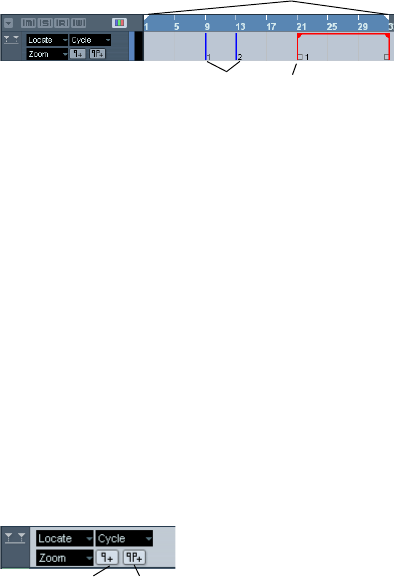
39
The Project window
The following actions can be performed in the Marker
window:
•Adding markers
Click the Add button or press [Ins] (Windows only) on the computer key-
board to add position markers at the current project cursor position.
Select “Cycle Markers” from the Show pop-up menu and click the Add
button to add a cycle marker between the left and right locator.
•Removing markers
Select a marker and click the Remove button to remove it.
•Moving marker positions
Set the project cursor to the position to which you want to move (or re-
program) a marker, select the marker that you want to change in the
Marker window and click the Move button. If a cycle marker is selected,
the Move operation affects the cycle marker start position, the length of
the range is not affected. You can also move markers by editing their po-
sition numerically in the Position column.
Editing markers on the Marker track
The Marker track is used for viewing and editing markers.
Any changes made on the Marker track are reflected in the
Marker window and vice versa. Standard position markers
are shown as vertical lines with the marker name (if as-
signed) and number beside it. If you select the Marker
track, all markers are shown in the Inspector.
To add the Marker track to the Project, select “Marker” from
the Add Track submenu of the Project menu (or right-click
in the Track list and select “Add Marker Track”). You can
only have one Marker track in a project.
The following editing functions can be performed directly
on the Marker track:
•Adding markers
Press the [Insert] key (Win) or the “Add Marker” button in the Track list,
to add a position marker at the current cursor position during playback.
Click the “Add Cycle Marker” button in the Track list, to add a cycle
marker at the left and right locator positions.
•Selecting markers
Use the standard techniques.
•Drawing markers
Use the Pencil tool (or press [Alt]/[Option] and use the Arrow tool) to
draw position markers. Snap is taken into account.
Hold down [Ctrl]/[Command] while using the Pencil or the Arrow tool to
draw cycle markers. Snap is taken into account.
•Resizing
Select and drag a cycle marker by the handles that appear at the bottom
of the start and end events to resize it. This can also be done numerically
on the info line.
•Moving
Click and drag, or edit the positions on the info line to move a marker.
Snap is taken into account if activated.
•Removing
Select a position marker and press [Delete] or use the Erase tool to re-
move it.
Click with the Erase tool to delete a cycle marker. If you hold down [Alt]/
[Option] when you click, all consecutive markers will also be deleted.
•Naming
Select a marker and enter a name on the info line.
•Moving the left and right locators
Double-click on a cycle marker or select it from the Cycle pop-up menu
in the Track list, to move the left and right locators to encompass the cy-
cle marker.
Use the numeric pad keys [1] and [2] to move the project cursor position
to the start or the end of the cycle marker. You can also use key com-
mands for this – see “Editing markers using key commands” on page 39.
•Zooming
Select a cycle marker on the Zoom pop-up menu, to zoom in the event
display to encompass the selected range only (see the section “Zoom
presets and Cycle markers” on page 24).
You can also do this by pressing [Alt]/[Option] and double-clicking on
the cycle marker in the event display.
•Making range selections in the Project window
Double-click with the Range Selection tool between any two markers to
create a selection range between the markers, spanning all tracks in the
project. This is a quick way to move or copy (hold down [Alt]/[Option])
complete sections of the project (on all tracks).
Editing markers using key commands
You can use key commands for marker operations, see
“Transport category” on page 274.
Cycle markerMarkers
Locators
Add Marker/Add Cycle Marker buttons
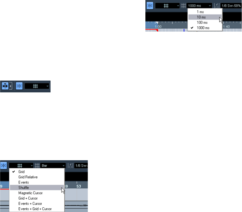
40
The Project window
Options
The Snap function
The Snap function helps you to find exact positions when
editing in the Project window. It does this by restricting
horizontal movement and positioning to certain positions.
Operations affected by Snap include moving, copying,
drawing, sizing, splitting, range selection, etc.
•You turn Snap on or off by clicking the Snap icon in the
toolbar.
Snap activated.
When you are moving audio events with Snap activated, it
isn’t necessarily the beginning of the event that is used as
Snap position reference. Instead, each audio event has a
snap point, which you can set to a relevant position in the
audio (such as a downbeat, etc.).
Exactly how Snap works depends on which mode is se-
lected on the Snap mode pop-up menu.
The following sections describe the different Snap
modes:
Grid
In this mode, the Snap positions are set with the Grid
Type pop-up menu to the right. The options depend on
the display format selected for the ruler. For example, if the
ruler is set to show bars and beats, the grid can be set to
bars, beats or the quantize value set with the next pop-up
menu to the right. If a time or frame-based ruler format is
selected, the Grid Type pop-up menu contains time or
frame-based grid options, etc.
When Seconds is selected as ruler format, the Grid Type pop-up menu
contains time-based grid options.
Grid Relative
When you move events and parts in this mode they will not
be “magnetic” to the grid. Rather, the grid determines the
step size for moving the events. This means that a moved
event will keep its original position relative to the grid.
For example, if an event starts at the position 3.04.01 (one
beat before bar 4), Snap is set to Grid Relative and the Grid
Type pop-up menu is set to “Bar”, you can move the event
in steps of one bar – to the positions 4.04.01, 5.04.01 and
so on. The event will keep its relative position to the grid, i.e.
stay one beat before the bar lines.
•This only applies when dragging existing events or parts
– when you create new events or parts this mode works
like the Grid mode.
Events
In this mode, the start and end positions of other events
and parts become “magnetic”. This means that if you drag
an event to a position near the start or end of another
event, it is automatically aligned with the start or end of the
other event. For audio events, the position of the snap
point is also magnetic (see “Adjusting the snap point” on
page 129).
•Note that this includes marker events on the marker
track.
This allows you to snap events to marker positions, and vice versa.
Shuffle
Shuffle mode is useful when you want to change the order
of adjacent events. If you have two adjacent events and
drag the first one to the right, past the second event, the
two events will change places.
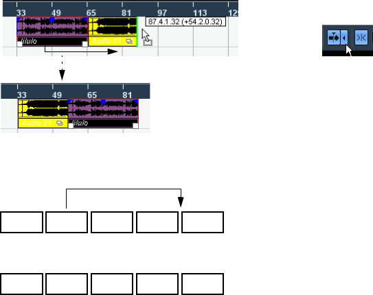
41
The Project window
The same principle works when changing the order of
more than two events:
Magnetic Cursor
When this mode is selected, the project cursor becomes
“magnetic”. Dragging an event near the cursor causes the
event to be aligned with the cursor position.
Grid + Cursor
This is a combination of the “Grid” and “Magnetic Cursor”
modes.
Events + Cursor
This is a combination of the “Events” and “Magnetic Cur-
sor” modes.
Events + Grid + Cursor
This is a combination of the “Events”, “Grid” and “Mag-
netic Cursor” modes.
Snap to Zero Crossing
When this option is activated on the toolbar or in the Prefer-
ences (Editing–Audio page), splitting and sizing of audio
events is done at zero crossings (positions in the audio
where the amplitude is zero). This helps you avoid pops and
clicks which might otherwise be caused by sudden ampli-
tude changes.
Autoscroll
“Autoscroll” and “Suspend Autoscroll when Editing” are activated
When the Autoscroll option is activated, the waveform dis-
play will scroll during playback, keeping the project cursor
visible in the window. You can find the Autoscroll button in
the toolbars of the Project window and all editors.
•If the option “Stationary Cursors” is activated in the
Preferences (Transport page), the project cursor will be
positioned in the middle of the screen (if possible).
Suspending autoscroll
When editing parts or events during playback with Auto-
scroll enabled, you may suddenly “loose sight” of the ed-
ited material as the display follows the project cursor.
If you don’t want the Project window display to change
when editing during playback, you can activate the “Sus-
pend Autoscroll when Editing” button. You will find this
button right next to the Autoscroll button. When this op-
tion is enabled, autoscrolling is suspended as soon as you
click anywhere in the event display during playback.
Proceed as follows:
1. Open a project that contains audio or MIDI parts/events.
2. Enable both the “Autoscroll” and the “Suspend Auto-
scroll when Editing” buttons (both buttons turn blue).
3. Start playback.
4. Edit an audio or MIDI part/event of your project (e.g.
click and drag it to a different location on its track).
The Autoscroll button will turn orange.
Autoscrolling is now suspended, i.e. when the project cur-
sor moves to the right edge of the Project window, the
display will not follow to keep the cursor visible.
As soon as playback stops, or when you click the Auto-
scroll button again (so it turns blue), Cubase AI will return
to the normal Autoscroll behavior.
12345
52431
Dragging event 2 past event 4…
…changes the order of events 2, 3 and 4.
4
Playback and the Transport panel
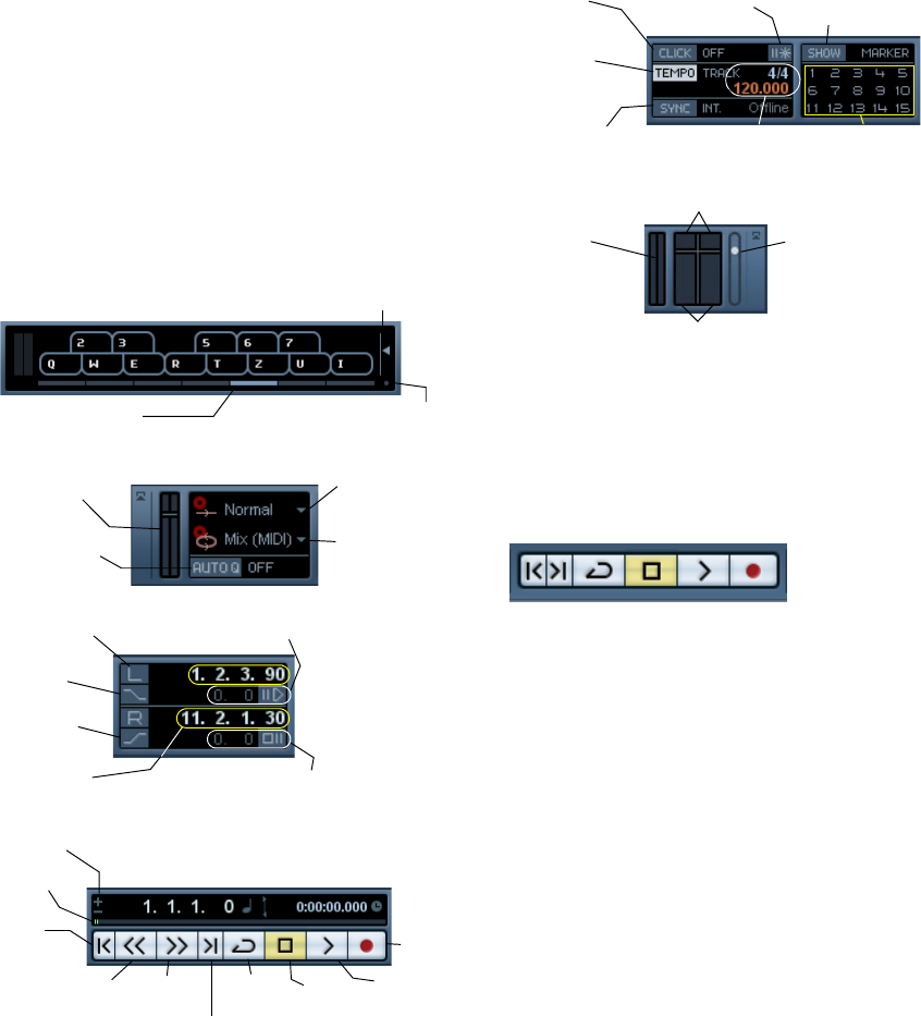
43
Playback and the Transport panel
Background
This chapter describes the various methods available for
controlling Playback and Transport functions in Cubase AI.
The Transport panel
Below you can find a brief description of each item on the
Transport panel.
The pictures below show the Transport panel with all con-
trols visible. The Transport panel is divided into the follow-
ing sections, from left to right.
ÖNote that the Output Activity and Clipping indicator as
well as the Output Level Control refer to the Main Mix
Output bus as defined on the Outputs tab in the VST
Connections window.
•The main Transport functions (Cycle/Stop/Play/Record)
can also be shown on the toolbar.
In addition, various play options are available on the Trans-
port menu.
Hiding and showing the Transport Panel
The Transport panel is shown automatically when you
launch a new project. To hide or show it, select “Transport
Panel” on the Transport menu (or use a key command – by
default [F2]).
About Pre-roll and Post-roll
These items are described in the chapter “Recording”,
see “About Pre-roll and Post-roll” on page 59.
Changing the Transport panel setup
You can customize the appearance of the Transport panel
by right-clicking anywhere on the panel and selecting/de-
selecting the corresponding options on the context menu.
This is described in detail in the section “The setup con-
text menus” on page 262.
Octave Offset
Note Velocity Level
Change Virtual Keyboard
Display Type
Activates Auto
Quantize
Record mode
pop-up menu
Cycle Record mode
pop-up menu
CPU load and
Disk Cache
meters
Right locator
Punch In
Left locator
Postroll: value and on/off
Preroll: value and on/off
Punch Out
Position
slider
Record
Play
Fast
forward
Go to next marker/ project end
Nudge position
right/left
Go to
previous
marker/
project
start Cycle
on/off Stop
Rewind
Tempo track
on/off
Synchronization
on/off The tempo and time
signature display
Metronome
click on/off Show Markers (opens
Marker window)
Jump to Marker
Precount on/off
MIDI In/Out
activity
(left/right)
Output Level
Control
Clipping indicators
Audio input/output activity
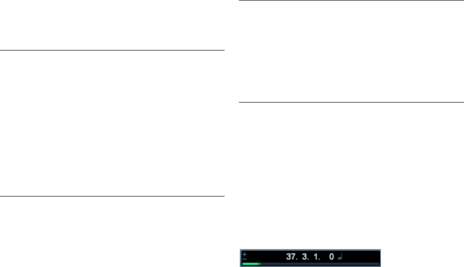
44
Playback and the Transport panel
The numeric keypad
In the default Key Command settings, various Transport
panel operations are assigned to the numeric keypad on
the computer keyboard. The keypads are slightly different
on PC and Macintosh computers:
Operations
Setting the project cursor position
There are several ways to move the project cursor position:
•By using Fast Forward and Rewind.
•By dragging the project cursor in the lower part of the
ruler.
•By clicking in the ruler.
Double-clicking in the ruler moves the cursor and starts/stops playback.
•If the option “Locate when Clicked in Empty Space” is
activated in the Preferences (Transport page) you can click
anywhere in an empty section of the Project window to
move the cursor position.
•By changing the value in any of the position displays.
•By using the position slider above the transport buttons
in the Transport panel.
The range of the slider relates to the Length setting in the Project Setup
dialog. Hence, moving the slider all the way to the right will take you to
the end of the project.
•By using markers (see “Markers” on page 38).
•By using playback options (see “Playback functions” on
page 46).
•By using functions on the Transport menu.
The following functions are available:
ÖIf Snap is activated when dragging the project cursor,
the Snap value is taken into account. This is helpful for
finding exact positions quickly.
ÖThere are also numerous key commands available for
moving the project cursor (in the Transport category in the
Key Commands dialog).
For example, you can assign key commands to the “Step Bar” and “Step
Back Bar” functions, allowing you to move the project cursor in steps of
one bar, backwards and forwards.
About the Transport panel display format
The time display in the Transport panel
The time unit shown in the ruler can be independent from
the time unit shown in the time display on the Transport
panel. This means that you can display timecode in the
transport position display and bars and beats in the ruler,
for example.
The following rules apply:
•If you change the time format of the time display on the
Transport panel, the time format of the ruler will be changed
as well.
This is the same as changing the display format in the Project Setup.
Therefore, to have different display formats in the ruler and the time dis-
play you should change the format in the ruler.
•The time display format is set on the pop-up menu to
the right in the position display.
•This setting also determines the time format displayed
for the left and right locators on the Transport panel.
Numeric Key Function
[Enter] Play
[+] Fast Forward
[-] Rewind
[*] Record
[÷] (Win)/[/] (Mac) Cycle On/Off
[,] Return to Zero
[0] Stop
[1] Go to Left Locator
[2] Go to Right Locator
[3-9] Go to marker 3 to 9
Function Description
Locate Selec-
tion/Locate
Selection End
Moves the project cursor to the beginning or end of the
current selection. For this to be available, you must
have selected one or more events or parts, or made a
selection range.
Locate Next/
Previous Marker This moves the project cursor to the closest marker to
the right or left (see “Marker tracks” on page 19).
Locate Next/
Previous Event This moves the project cursor forwards or backwards
respectively, to the closest beginning or end of any
event on the selected track(s).

45
Playback and the Transport panel
The left and right locators
The left and right locators are a pair of position markers
used for specifying punch-in and punch-out positions dur-
ing recording, and as boundaries for cycle playback and
recording.
ÖWhen cycle mode is activated on the Transport panel,
the area between the left and right locator will be repeated
(cycled) on playback.
However, if the right locator is positioned before the left, this will work as
a “jump” or “skip mode” – when the project cursor reaches the right lo-
cator it will immediately jump to the left locator position and continue
playback from there.
There are several ways to set locator positions:
•To set the left locator, press [Ctrl]/[Command] and click
at the desired position in the ruler.
Similarly, pressing [Alt]/[Option] and clicking in the ruler sets the right lo-
cator. You can also drag the locator “handles” directly in the ruler.
The locators are indicated by the “flags” in the ruler. The area between
the locators is highlighted in the ruler and in the Project window (see
“Appearance” on page 265). Note that if the right locator is before the
left locator, the color of the ruler between the locators will change (from
blue to red).
•Click and drag in the upper half of the ruler to “draw” a
locator range.
If you click on an existing locator range, you can drag to move it.
•Pressing [Ctrl]/[Command] and pressing [1] or [2] on
the numeric keypad sets the left or right locator to the
project cursor position.
Similarly, you can press [1] or [2] on the numeric keypad (without [Ctrl]/
[Command]) to set the project cursor position to the left or right locator
position. Note that these are default key commands – you can change
these if you like.
•By creating cycle markers you can store any number of
left and right locator positions, which can be recalled by
simply double-clicking on the corresponding marker (see
“Editing markers on the Marker track” on page 39).
•The “Locators to Selection” item on the Transport menu
(default key command [P]) sets the locators to encompass
the current selection.
This is available if you have selected one or several events or made a se-
lection range.
•You can also adjust the locators numerically on the
Transport panel.
Clicking the L/R buttons in the locator section on the Transport panel will
move the project cursor to the respective locator. If you press [Alt]/[Op-
tion] and click the L or R button, the corresponding locator will be set to
the current project cursor position.
Options and Settings
The “Return to Start Position on Stop”
preference
This setting is found on the Transport page in the Prefer-
ences (found on the File menu under Windows, or on the
Cubase AI menu under Mac OS X).
•If “Return to Start Position on Stop” is activated when
you stop playback, the project cursor will automatically re-
turn to the position where recording or playback last
started.
•If “Return to Start Position on Stop” is deactivated, the
project cursor will remain at the position where you stop
playback.
Pressing Stop again will return the project cursor to the position where
recording or playback last started.
About track disable/enable
For audio tracks, the track context menu contains an item
named “Disable Track”. This shuts down all disk activity for
the track, as opposed to using Mute, which merely turns
down the output volume for a track. For example, if you of-
ten record “alternative takes” you can easily build up a large
number of takes on different tracks. Even though these
tracks are muted, they are actually still “playing back” from
the hard disk during playback. This puts an unnecessary
load on your disk system, so using “Disable Track” is rec-
ommended for such situations.
•Select “Disable Track” for tracks that you want to keep in
the project for later use but do not want to play back now.
The track color changes to indicate that the track is disabled.
•Select “Enable Track” from the track context menu to
re-enable disabled tracks.
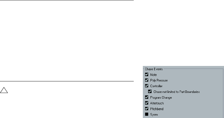
46
Playback and the Transport panel
Playback functions
Apart from the standard transport controls on the Trans-
port panel, you can also find a number of functions on the
Transport menu that can be used to control playback. The
items have the following functionality:
ÖIn the Preferences dialog (Editing–Audio page) you
will find the option “Treat Muted Audio Events like De-
leted”. When you activate this option, any events over-
lapped by a muted event will become audible.
About Chase
Chase is a function that makes sure your MIDI instruments
sound as they should when you locate to a new position
and start playback. This is accomplished by the program
transmitting a number of MIDI messages to your instru-
ments each time you move to a new position in the project,
making sure all MIDI devices are set up correctly with re-
gard to program change, controller messages (such as
MIDI Volume), etc.
For example, let’s say you have a MIDI track with a pro-
gram change event inserted at the beginning. This event
makes a synth switch to a piano sound.
At the beginning of the first chorus you have another pro-
gram change event which makes the same synth switch to
a string sound.
You now play back the song. It begins with the piano sound
and then switches to the string sound. In the middle of the
chorus you stop and rewind to some point between the be-
ginning and the second program change. The synth will
now still play the string sound although in this section it re-
ally should be a piano!
The Chase function takes care of that. If program change
events are set to be chased, Cubase AI will track the music
back to the beginning, find the first program change and
transmit it to your synth, setting it to the correct sound.
The same thing can apply to other event types as well. The
Chase Events settings in the Preferences dialog (MIDI
page) determine which event types will be chased when
you locate to a new position and start playback.
ÖEvent types for which the checkbox is activated here
will be chased.
•In this section of the Preferences dialog, you will also
find the option “Chase not limited to Part Boundaries”.
When you activate this option, MIDI controllers are also chased outside
the part boundaries, i.e. the Chase will be performed on the part touched
by the cursor as well as on all the parts to the left of it. Please note that
this option should be deactivated for very large projects, as it consider-
ably slows down operations such as positioning and soloing. When you
deactivate this option, the MIDI controllers are only chased within the
parts under the position cursor.
Option Description
Play from Selection
Start/End Activates playback from the beginning or end of
the current selection.
Play until Selection
Start/End Activates playback two seconds before the start or
end of the current selection and stops at the selec-
tion start or end, respectively.
Play until Next Marker This activates playback from the project cursor and
stops at the next marker.
Play Selection Range This activates playback from the start of the current
selection and stops at the selection end.
Loop Selection This activates playback from the start of the current
selection and keeps starting over again when
reaching the selection end.
!
The functions listed above (except “Play until Next
Marker”) are only available if you have selected one
or more events or made a selection range.
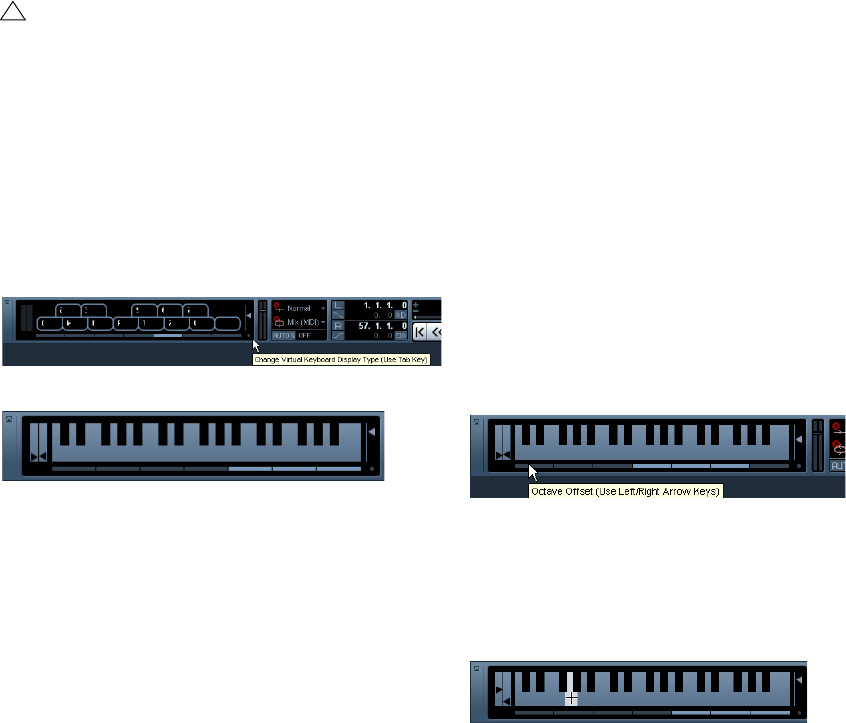
47
Playback and the Transport panel
The Virtual Keyboard
The Virtual Keyboard can be displayed in the Transport
panel. It allows you to play and record MIDI notes by using
your computer keyboard or mouse. This is useful if you have
no external MIDI instrument at hand and you do not want to
draw in notes with the Pencil tool. The Virtual Keyboard can
perform all functions that can be controlled by external MIDI
keyboards, e.g. playing and recording MIDI notes.
•You can choose between two different keyboard dis-
play modes: computer keyboard and piano keyboard. To
switch between these two modes, click the “Change Vir-
tual Keyboard Display Type” button or use the [Tab] key.
The Virtual Keyboard in computer keyboard display mode
The Virtual Keyboard in piano keyboard display mode
To record MIDI using the Virtual Keyboard, proceed as fol-
lows:
1. Create or choose a MIDI or an instrument track and ac-
tivate the “Record Enable” button for it.
2. Open the Virtual Keyboard by selecting “Virtual Key-
board” on the Devices menu or by pressing [Alt]/[Option]-
[K]. You can also open the Virtual Keyboard by right-click-
ing on the Transport panel and selecting “Virtual Keyboard”
on the context menu.
The Virtual Keyboard is displayed in the Transport panel.
3. Activate the Record button and press a key on your
computer keyboard to enter a note.
You can also click on the keys of the Virtual Keyboard to enter notes.
•You can also press several keys simultaneously to enter
polyphonic parts. The maximum number of notes that can
be played at one time varies between the different operat-
ing systems and hardware configurations.
4. Use the fader “Note velocity level” to the right of the
virtual keyboard to adjust the volume.
You can also use the up and down arrow keys for this.
5. Enter the desired notes this way.
6. When you are done, hit the Stop button and close the
Virtual Keyboard.
When the Virtual Keyboard is hidden, all key commands are available
again.
Options and settings
•In piano keyboard mode, you have a wider range of keys
at your disposal, allowing you to enter two voices simulta-
neously, for example bass and lead voice or bass drums
and HiHats.
In computer keyboard mode, you can use the two rows of keys that are dis-
played on the Virtual Keyboard to enter notes. In piano keyboard mode, you
can also use the two rows of keys below these.
•You have seven full octaves at your disposal. Use the
“Octave Offset” buttons at the bottom of the virtual key-
board to offset the octave range of the keyboard.
You can also use the left and right arrow keys to switch the keyboard range
to a lower or higher octave, respectively.
•In piano keyboard mode, you can use the two sliders to
the left of the keyboard to introduce pitchbend (left slider)
or modulation (right slider).
You can also click on a key, hold the mouse button pressed until the
mouse pointer becomes a crosshair tool and drag upwards/downward to
introduce modulation or left/right to create pitchbend.
!
When the Virtual Keyboard is displayed, the usual key
commands are blocked because they are reserved for
the Virtual Keyboard. The only exceptions are: [Ctrl]/
[Command]-[S] (Save), Num [*] (Start/Stop Record),
[Space] (Start/Stop Playback), Num [1] (Jump to left
locator), [Delete] or [Backspace] (Delete), Num [/]
(Cycle on/off), [F2] (Show/Hide Transport panel), and
[Alt]/[Option]-[K] (Show/Hide Virtual Keyboard).
5
Recording
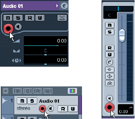
49
Recording
Background
This chapter describes the various recording methods
that you can use in Cubase AI. As it is possible to record
both audio and MIDI tracks, both recording methods are
covered in this chapter.
Before you start
This chapter assumes that you are reasonably familiar with
certain basic recording concepts, and that the following
initial preparations have been made:
•You have properly set up, connected and calibrated
your audio hardware.
•You have opened a project and set the project setup
parameters to your specifications.
Project setup parameters determine the record format, sample rate, project
length etc. that affect the audio recordings you make during the course of
the project, see “The Project Setup dialog” on page 22.
•If you plan to record MIDI, your MIDI equipment should
be set up and connected correctly.
Basic recording methods
This section describes the general methods used for re-
cording. However, there are additional preparations and
procedures that are specific to audio and MIDI recording
respectively. Make sure to read these sections before you
start recording (see “Audio recording specifics” on page
51 and “MIDI recording specifics” on page 55).
Record-enabling tracks
Cubase AI can record on a single track or on several
tracks (audio and/or MIDI) simultaneously. To make a
track ready for recording, click the Record Enable button
for the track in the Track list, in the Inspector or in the
mixer. When activated, the buttons turn red, indicating
record ready mode.
Record Enable in the Inspector, Track list and mixer
ÖIf the option “Enable Record on Selected Track” is ac-
tivated in the Preferences (Editing–Project & Mixer page),
tracks are automatically record-enabled when you select
them in the Track list.
ÖThe exact number of audio tracks you can record si-
multaneously depends on your computer CPU and hard
disk performance.
In the Preferences (VST page), you can find the option “Warn on Proces-
sing Overloads”. When this is activated, a warning message will be dis-
played as soon as the CPU clip indicator (on the Transport panel) lights
up during recording.
Manually activating recording
You activate recording by clicking the Record button on
the Transport panel or toolbar or by using the correspond-
ing key command (by default [*] on the numeric keypad).
Recording can be activated in Stop mode (from the current
cursor position or from the left locator) or during playback:
•If you activate recording in Stop mode, and the option
“Start Record at Left Locator” is activated on the Trans-
port menu, recording will start from the left locator.
The pre-roll setting or the metronome count-in will be applied (see
“About Pre-roll and Post-roll” on page 59).
•If you activate recording in Stop mode, and “Start Record
at Left Locator” is deactivated, recording will start from the
current project cursor position.
•If you activate recording during playback, Cubase AI will
immediately enter Record mode and start recording from
the current project cursor position.
This is known as “manual punch in”.
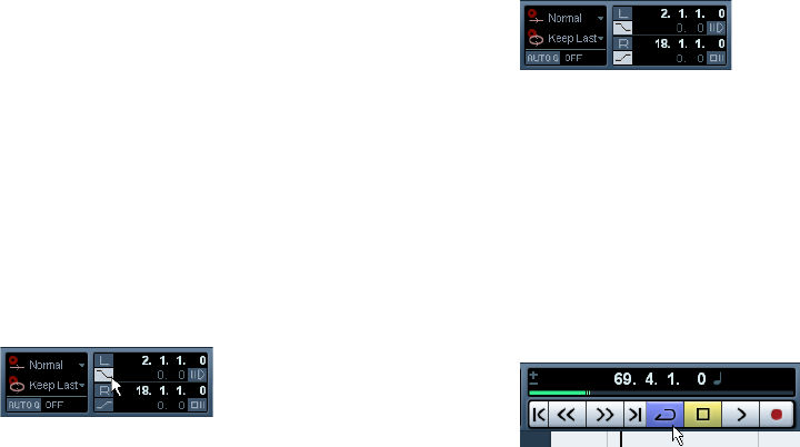
50
Recording
Activating recording in Sync mode
If you are synchronizing the Cubase AI transport to external
equipment (Sync is activated on the Transport panel) and
you activate recording, the program will go into “record
ready” mode (the record button on the Transport panel will
light up). In this case, recording will start when a valid time-
code signal is received (or when you click the Play button).
See the chapter “Synchronization” on page 232 for more
information.
Automatically activating recording
Cubase AI can automatically switch from playback to re-
cording at a given position. This is known as “automatic
punch in”. A typical use for this would be if you need to re-
place a section of a recording, and want to listen to what is
already recorded, up to the recording start position.
1. Set the left locator to the position where you want re-
cording to start.
2. Activate the Punch In button on the Transport panel.
Punch In activated
3. Activate playback from some position before the left
locator.
When the project cursor reaches the left locator, recording is automati-
cally activated.
Stopping recording
Again, this can be done automatically or manually:
•If you click the Stop button on the Transport panel (or
use the corresponding key command, by default [0] on the
numeric keypad), recording is deactivated and Cubase AI
goes into Stop mode.
•If you click the Record button (or use the key command
for recording, by default [*]), recording is deactivated but
playback continues.
This is known as “manual punch out”.
•If the Punch Out button is activated on the Transport
panel, recording will be deactivated when the project cur-
sor reaches the right locator.
This is known as “automatic punch out”. By combining this with automatic
punch in, you can set up a specific section to record – again very useful if
you want to replace a certain part of a recording (see also “Stop after Au-
tomatic Punch Out” on page 59).
Punch In and Out activated
Cycle recording
Cubase AI can record and play back in a cycle – a loop.
You specify where the cycle starts and ends by setting the
left and right locators. When the cycle is active, the se-
lected section is seamlessly repeated until you hit Stop or
deactivate cycle mode.
•To activate cycle mode, click the cycle button on the
Transport panel.
Cycle activated
•To record in cycle mode, you can start recording from
the left locator, from before the locators or from within the
cycle, in Stop mode or during playback.
As soon as the project cursor reaches the right locator, it will jump back
to the left locator and continue recording a new lap.
•The results of cycle recording depend on the selected
cycle record mode and are different for audio (see “Re-
cording audio in cycle mode” on page 54) and MIDI (see
“Recording MIDI in cycle mode” on page 57).

51
Recording
Audio recording specifics
Selecting a recording file format
The format for recorded files is set in the Project Setup dia-
log on the Project menu. There are three settings: sample
rate, record format (bit depth) and record file type. While
the sample rate is set once and for all when you start work-
ing on a new project, the bit depth and file type can be
changed at any time.
Record file type
The Record File Type setting determines which type of
files will be created when you record:
Record format (bit depth)
The available options are 16 bit and 24 bit. Use the follow-
ing guidelines:
•Normally, select the record format according to the bit
depth delivered by your audio hardware.
For example, if your audio hardware has 20 bit A/D converters (inputs),
you may want to record at 24 bit resolution to capture the full bit depth.
On the other hand, if your hardware has 16 bit inputs, it is pointless to
record with a higher bit depth – this will only make the audio files larger,
with no difference in audio quality.
•The higher the bit depth, the larger the files and the
more strain is put on the disk system.
If this is an issue, you may want to lower the record format setting.
Setting up the track
Creating a track and selecting the channel configuration
Audio tracks can be configured as mono or stereo tracks.
This allows you to record or import a file containing multi-
ple channels and treat it as one entity, with no need to split
it up into several mono files etc. The signal path for an au-
dio track maintains its channel configuration all the way
from the input bus, via EQ, level and other mixer settings
to the output bus.
You specify the channel configuration for a track when you
create it:
1. Select “Add Audio Track” from the Track list context
menu or the Project menu (or, if an audio track is already
selected, double-click in an empty area of the Track list).
A dialog appears with a channel configuration pop-up menu.
2. Select the desired format from the pop-up menu.
You can choose between mono and stereo.
•The Browse item in this dialog allows you to browse
your disk(s) for created Track Presets, which can be used
as a basis (or template) for tracks.
This is described in detail in the chapter “Working with Track Presets” on
page 155.
3. Click OK.
A track appears, set to the specified channel configuration. In the mixer,
a corresponding channel strip appears. You cannot change the channel
configuration for a track.
File type Description
Wave File Wave files have the extension “.wav” and are a common
file format on the PC platform.
AIFF File Audio Interchange File Format, a standard defined by Ap-
ple Inc. AIFF files have the extension “.aif” and are used
on most computer platforms. AIFF files can contain em-
bedded text strings (see below).
!
For further information on the options in the Project
Setup dialog, see “The Project Setup dialog” on
page 22.
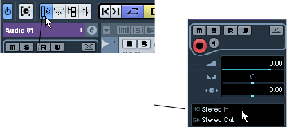
52
Recording
Selecting an input bus for a track
Here we assume that you have added and set up the re-
quired input busses (see “Setting up busses” on page
10). Before you record, you need to specify from which in-
put bus the track should record. You can do this in the In-
spector.
•Select an input bus on the Input Routing pop-up menu
in the top section.
As described in the section “The Inspector” on page 18, the Inspector
shows the settings for the selected track. You show or hide the Inspector
by clicking the “Show/Hide Inspector” button on the Project window
toolbar.
Setting input levels
When recording digital sound, it is important to set the in-
put levels correctly – loud enough to ensure low noise and
high audio quality, but not so loud that clipping (digital dis-
tortion) occurs.
Clipping typically occurs in the audio hardware when a
too loud analog signal is converted to digital in the hard-
ware’s A/D converters.
You need to check the level at the channel strip for the
track on which you are recording:
1. Locate the channel strip for the track you’re about to
record on.
2. Activate monitoring for the channel by clicking the
speaker button next to the fader.
When monitoring is activated, the meter shows the level of the incoming
audio signal.
3. Play the audio source that you want to record and
check the level meter for the channel.
4. Adjust the output level of your audio source so that the
meters go reasonably high without reaching 0.0dB.
Check the numerical peak level indicator below the meter in the bus
channel strip. To reset the peak level indicator, click on it.
ÖYou must adjust the output level of the audio source –
you cannot use the faders in Cubase AI to adjust the input
level!
ÖAn alternative way of checking the input levels would
be to use the control panel for your audio hardware (if it
features input level meters). It may also be possible to ad-
just the input level in the control panel.
See the documentation of your audio hardware for details.
Monitoring
In this context, “monitoring” means listening to the input
signal during recording. There are three fundamentally dif-
ferent ways to do this: via Cubase AI, externally (by listening
to the signal before it reaches Cubase AI), or by using
ASIO Direct Monitoring (which is a combination of both
other methods – see below).
Monitoring via Cubase AI
If you monitor via Cubase AI, the input signal is mixed in
with the audio playback. The advantage of this is that you
can adjust the monitoring level and panning in the mixer,
and add effects and EQ to the monitor signal just as dur-
ing playback (using the track’s channel strip – not the in-
put bus!).
The disadvantage of monitoring via Cubase AI is that the
monitored signal will be delayed according to the latency
value (which depends on your audio hardware and driv-
ers). Therefore, monitoring via Cubase AI requires an au-
dio hardware configuration with a low latency value. You
can check the latency of your hardware in the Device
Setup dialog (VST Audio System page).
ÖIf you are using plug-in effects with large inherent de-
lays, the automatic delay compensation function in Cubase
AI will increase the latency.
If this is a problem, you can use the Constrain Delay Compensation func-
tion while recording, see “Constrain Delay Compensation” on page 106.
Click here to select an input
bus for the track.
Click here to show/hide
the Inspector.
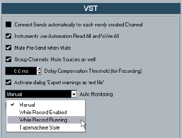
53
Recording
When monitoring via Cubase AI, you can select one of four
Auto Monitoring modes in the Preferences (VST page):
•Manual
This option allows you to turn input monitoring on or off by clicking the
Monitor button in the Inspector, the Track list or in the mixer.
•While Record Enabled
With this option, you will hear the audio source connected to the channel
input whenever the track is record enabled.
•While Record Running
This option switches to input monitoring only during recording.
•Tapemachine Style
This option emulates standard tapemachine behavior: input monitoring in
Stop mode and during recording, but not during playback.
External monitoring
External monitoring (listening to the input signal before it
goes into Cubase AI) requires some sort of external mixer
for mixing the audio playback with the input signal. This
can be a stand-alone physical mixer or a mixer application
for your audio hardware, if this has a mode in which the in-
put audio is sent back out again (usually called “Thru”,
“Direct Thru” or similar).
When using external monitoring, you cannot control the
level of the monitor signal from within Cubase AI or add
VST effects or EQ to the monitor signal. The latency value
of the audio hardware configuration does not affect the
monitor signal in this mode.
ÖIf you want to use external monitoring, you need to make
sure that monitoring via Cubase AI is not activated as well.
Select the “Manual” monitoring mode in the Preferences (VST page) and
do not activate the Monitor buttons.
ASIO Direct Monitoring
If your audio hardware is ASIO 2.0 compatible, it may sup-
port ASIO Direct Monitoring (this feature may also be avail-
able for audio hardware with Mac OS X drivers). In this
mode, the actual monitoring is done in the audio hardware,
by sending the input signal back out again. However, moni-
toring is controlled from Cubase AI. This means that the au-
dio hardware’s direct monitoring feature can be turned on
or off automatically by Cubase AI, just as when using inter-
nal monitoring.
•To activate ASIO Direct Monitoring, open the Device
Setup dialog on the Devices menu and activate the Direct
Monitoring checkbox on the page for your audio hardware.
If the checkbox is grayed out, your audio hardware (or its driver) does not
support ASIO Direct Monitoring. Consult the audio hardware manufac-
turer for details.
•When ASIO Direct Monitoring is activated, you can se-
lect a monitoring mode in the Preferences (VST page), as
when monitoring via Cubase AI (see “Monitoring via Cu-
base AI” on page 52).
•Depending on the audio hardware, it may also be possi-
ble to adjust the monitoring level and panning from the
mixer by adjusting the volume faders, and the input gain
controls.
Consult the documentation of the audio hardware if in doubt.
•VST effects and EQ cannot be applied to the monitor
signal in this mode, since the monitor signal does not pass
through Cubase AI.
•Depending on the audio hardware, there may be special
restrictions as to which audio outputs can be used for di-
rect monitoring.
For details on the routing of the audio hardware, see its documentation.
The latency value of the audio hardware configuration
does not affect the monitor signal when using ASIO Direct
Monitoring.
When using Steinberg hardware (MR816 series) in com-
bination with ASIO Direct Monitoring, monitoring will be
virtually latency-free.
ÖIf you are using RME Audio Hammerfall DSP audio
hardware, make sure that the pan law is set to -3dB in the
card’s preferences.
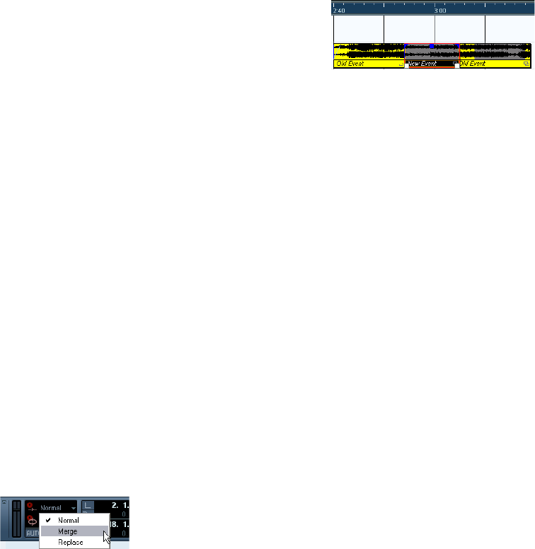
54
Recording
Recording
Recording is done using any of the general recording meth-
ods (see “Basic recording methods” on page 49). When
you finish recording, an audio file is created in the Audio
folder within the project folder. In the Pool, an audio clip is
created for the audio file, and an audio event that plays the
whole clip appears on the recording track. Finally, a wave-
form image is calculated for the audio event. If the recording
was very long, this may take a while.
ÖIf the option “Create Audio Images During Record” is
activated in the Preferences (Record–Audio page), the
waveform image will be calculated and displayed during
the actual recording process.
This realtime calculation uses some processing power – if your proces-
sor is slow or you are working on a CPU-intensive project, you should
consider turning this option off.
Undoing recording
If you decide that you do not like what you just recorded,
you can delete it by selecting Undo from the Edit menu.
The following will happen:
• The event(s) you just created will be removed from the Project
window.
• The audio clip(s) in the Pool will be moved to the Trash folder.
• The recorded audio file(s) will not be removed from the hard
disk.
However, since their corresponding clips are moved to
the Trash folder, you can delete the files by opening the
Pool and selecting “Empty Trash” from the Media menu,
see “Deleting from the hard disk” on page 147.
Recording overlapping events
The basic rule for audio tracks is that each track can play
back a single audio event at a time. This means that if two
or more events are overlapping, only one of them will be
heard at any given time.
What happens when you record overlapping events
(record in an area where there are already events on the
track) depends on the Linear Record Mode setting on the
Transport panel:
•In “Normal” or “Merge” mode, recording where some-
thing has already been recorded creates a new audio
event that overlaps the previous one(s).
When you record audio, there is no difference between “Normal” and
“Merge” mode – the difference only applies to MIDI recording (see
“About overlap and the Record Mode setting” on page 56).
•In “Replace” mode, existing events (or portions of events)
that are overlapped by the new recording will be removed.
This means that if you record a section in the middle of a longer existing
recording, the original event will be cut into two events with a gap for the
new event.
Which event will be heard?
If two or more events are overlapping, you will only hear the
events (or portions of events) that are actually visible. Over-
lapped (hidden) events or sections are not played back.
•The functions “Move to Front” and “Move to Back” on
the Edit menu (Move submenu, see “Moving events” on
page 30) are useful for managing overlapping events, as is
the “To Front” function (see below).
Recording audio in cycle mode
If you are recording audio in cycle mode, the last complete
“take” (the last completely recorded lap) is kept as an au-
dio event.
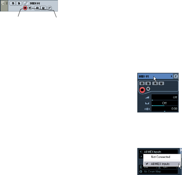
55
Recording
MIDI recording specifics
Activating MIDI Thru
Normally, when working with MIDI, you will have MIDI Thru
activated in Cubase AI, and Local Off selected in your MIDI
Instrument(s). In this mode, everything you play during re-
cording will be “echoed” back out again on the MIDI output
and channel selected for the recording track.
1. Make sure the option “MIDI Thru Active” is activated in
the Preferences (MIDI page).
2. Record enable the track(s) on which you want to
record.
Now, incoming MIDI is “echoed” back out again for all record-enabled
MIDI tracks.
ÖIf you just want to use the Thru function for a MIDI
track without recording, activate the monitor button for the
track instead.
This is useful e.g. if you want to try out different sounds or play a VST
instrument in realtime without recording your playing.
Setting MIDI channel, input and output
Setting the MIDI channel in the instrument
Most MIDI synthesizers can play several sounds at the
same time, each on a different MIDI channel. This is the
key to playing back several sounds (bass, piano etc.) from
the same instrument. Some devices (such as General
MIDI compatible sound modules) always receive on all 16
MIDI channels. If you have such an instrument, there is no
specific setting you need to make in the instrument. On
other instruments, you will have to use the front panel con-
trols to set up a number of “Parts”, “Timbres” or similar so
that they receive on one MIDI channel each. See the man-
ual that came with your instrument for more information.
Naming MIDI ports in Cubase AI
MIDI inputs and outputs are often displayed with unneces-
sarily long and complicated names. However, you can re-
name your MIDI ports to more descriptive names:
1. Open the Device Setup dialog from the Devices menu.
2. Select the MIDI Port Setup item in the Device list.
The available MIDI inputs and outputs are listed. Under Windows, which
device to choose depends on your system.
3. To change the name of a MIDI port, click in the “Show
As” column and type in a new name.
After closing the dialog, the new name will appear on the MIDI Input and
Output Routing pop-up menus.
Setting the MIDI input in the Inspector
You select MIDI inputs for tracks in the Inspector (the area
to the left of the Track list in the Project window):
1. If the Inspector is hidden, click the Show Inspector
button on the toolbar.
2. Select the track(s) by clicking in the Track list.
To select multiple tracks, press [Shift] or [Ctrl]/[Command] and click. The
Inspector shows the settings for the first selected track (for details, see
“The Inspector” on page 18).
3. Click the track name in the Inspector to make sure the
topmost section is shown.
4. Pull down the Input Routing pop-up menu and select
an input.
The available MIDI inputs are shown. The items on the menu depend on
the type of MIDI interface you are using, etc.
•If you select the “All MIDI Inputs” option, the track will
receive MIDI data from all available MIDI inputs.
Record Enable button Monitor button
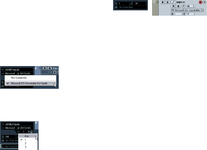
56
Recording
•If you hold down [Shift]-[Alt]/[Option] and select a MIDI
input, this will be used for all selected MIDI tracks.
Setting the MIDI channel and output
The MIDI channel and output settings determine where
the recorded MIDI is routed during playback, but are also
relevant for MIDI Thru in Cubase AI. Channel and output
can be selected in the Track list or in the Inspector. The
procedure below describes how to make the settings in
the Inspector, but it can be done in largely the same man-
ner in the Track list as well.
1. To select the track(s) and show the settings in the
Inspector, proceed as when selecting a MIDI input (see
above).
2. Pull down the Output Routing pop-up menu and se-
lect an output.
The available MIDI outputs are shown. The items on the menu depend on
what type of MIDI interface you are using etc.
•If you hold down [Shift]-[Alt]/[Option] and select a MIDI
output, this is selected for all selected MIDI tracks.
3. Use the Channel pop-up menu to select a MIDI chan-
nel for the track.
•If you set the track to MIDI channel “Any”, each MIDI
event on the track will be sent out on the channel stored in
the event itself.
In other words, the MIDI material will be played back on the channel(s)
used by the MIDI input device (the MIDI instrument you play during re-
cording).
Selecting a sound
You can select sounds from within Cubase AI by instruct-
ing the program to send Program Change and Bank Se-
lect messages to your MIDI device. This is done using the
“Patch Selector” and “Bank Selector” fields in the Inspec-
tor or Track list.
Program Change messages give access to 128 different
program locations. If your MIDI instruments have more
than 128 programs, Bank Select messages (set in the
“Bank Selector” field) allow you to select different banks,
each containing 128 programs.
ÖBank Select messages are recognized differently by
different MIDI instruments. The structure and numbering
of banks and programs may also vary. Consult the docu-
mentation of your MIDI instruments for details.
Recording
Recording MIDI is done according to the basic recording
methods (see “Basic recording methods” on page 49).
When you finish recording, a part containing MIDI events
is created in the Project window.
About overlap and the Record Mode setting
MIDI tracks are different from audio tracks when it comes
to overlapping parts:
ÖAll events in overlapping parts are always played back.
If you record several parts at the same locations (or move parts so that
they overlap), you will hear the events in all parts on playback, even
though some of the parts are obscured in the Project window.
When recording overlapping parts, the result depends on
the Linear Record Mode setting on the Transport panel:
• If the record mode is set to “Normal”, overdub recording
works as with audio tracks, i.e. if you record again where
something has already been recorded, you get a new part that
overlaps the previous one(s).
• If the record mode is set to “Merge”, the overdubbed events
are added to the existing part.
• If the record mode is set to “Replace”, the new recording re-
places any existing events in the area on that track.

57
Recording
About punch in and out on MIDI tracks
Performing and setting up manual and automatic punch
in/out recording for MIDI tracks is done in exactly the
same way as for audio tracks. There is one thing to note,
however:
•Punching in and out on recordings with Pitchbend or
controller data (modulation wheel, sustain pedal, volume
etc.) may lead to strange effects (apparently hanging
notes, constant vibrato etc.).
If this happens, you may need to use the Reset item on the MIDI menu
(see “The Reset function” on page 58).
About the Automatic MIDI Record Quantize function
If Auto Quantize is activated on the Transport panel (the
“Auto Q” button), the notes you record are automatically
quantized according to the current Quantize settings. For
more information about quantizing, see “The Quantizing
functions” on page 172.
Recording MIDI in cycle mode
When you record MIDI in cycle mode, the result depends
on which Cycle Record mode is selected on the Transport
panel:
Cycle Record mode: Mix (MIDI)
For each completed lap, everything you record is added to
what was previously recorded in the same part. This is use-
ful for building up rhythm patterns, for example. Record a
hi-hat part on the first lap, the bass drum part on the sec-
ond lap etc.
Cycle Record mode: Overwrite (MIDI)
As soon as you play a MIDI note (or send any MIDI mes-
sage), all MIDI you have recorded on previous laps is over-
written from that point on in the part. An example:
1. You start recording in an eight bar cycle.
2. The first take was not good enough – you start directly
with a new take on the next cycle lap and overwrite the
first take.
3. After recording the second take you let the recording
roll on and listen, without playing anything.
You find that the take was good up until bar seven, for example.
4. On the next lap, you wait until bar seven and start
playing.
This way you will overwrite the last two bars only.
5. Make sure you stop playing before the next lap begins
– otherwise you will overwrite the entire take.
Cycle Record mode: Keep Last
Each completed lap replaces the previously recorded lap.
Note the following:
•The cycle lap must be completed – if you deactivate re-
cording or press Stop before the cursor reaches the right
locator, the previous take will be kept.
•If you do not play or input any MIDI during a lap, nothing
happens (the previous take will be kept).
Recording different types of MIDI messages
Notes
When you press and release a key on your synth or other
MIDI keyboard, a Note On (key down) and a Note Off (key
up) message are sent out. The MIDI note message also
contains the information which MIDI channel was used.
Normally, this information is overridden by the MIDI channel
setting for the track, but if you set the track to MIDI channel
“Any”, the notes will be played back on their original chan-
nels.
Continuous messages
Pitchbend, aftertouch and controllers (like modulation
wheel, sustain pedal, volume etc.) are considered as MIDI
continuous events (as opposed to the momentary key
down and key up messages). If you move the Pitchbend
wheel on your synthesizer while recording, this movement
is recorded together with the key (Note On and Note Off
messages), just as you’d expect. But the continuous mes-
sages can also be recorded after the notes have been re-
corded (or even before). They can also be recorded on
their own tracks, separately from the notes to which they
belong.
!
You can decide exactly which event types should be
recorded by using the MIDI filters – see “Filtering
MIDI” on page 59.
58
Recording
Say, for instance, that you record one or several bass
parts on track 2. If you now set another track, like track 55,
to the same output and MIDI channel as track 2, you can
make a separate recording of just pitchbends for the bass
parts on track 55. This means that you activate recording
as usual and only move the pitchbend wheel during the
take. As long as the two tracks are set to the same output
and MIDI channel, it will appear to the MIDI instrument as
if the two recordings were made at the same time.
Program Change messages
Normally, when you switch from one program to another
on your keyboard (or whatever you use to record), a num-
ber corresponding to that program is sent out via MIDI as
a Program Change message. These can be recorded on
the fly with the music, recorded afterwards on a separate
track, or manually entered in the Key or List Editors.
System Exclusive messages
System Exclusive (SysEx) is a special type of MIDI mes-
sage used to send data that only makes sense to a unit of
a certain make and type. SysEx can be used to transmit a
list of the numbers that make up the settings of one or
more sounds in a synth. For details about viewing and ed-
iting SysEx messages, see the section “Working with Sys-
tem Exclusive messages” on page 210.
The Reset function
The Reset function on the MIDI menu sends out note-off
messages and resets controllers on all MIDI channels.
This is sometimes necessary if you experience hanging
notes, constant vibrato, etc.
There are two other options to perform a reset:
•Cubase AI can automatically perform a MIDI reset on
stop.
You can turn this function on or off in the Preferences (MIDI page).
•Cubase AI can automatically insert a reset event at the
end of a recorded part.
Open the Preferences (MIDI page) and activate the option “Insert Reset
Events after Record”. The inserted Reset event will reset controller data
such as Sustain, Aftertouch, Pitchbend, Modulation, Breath Control, etc.
This is useful if a MIDI part is recorded and e.g. the Sustain pedal is still
held after stopping recording. Usually, this would cause all following parts
to be played with Sustain, as the Pedal Off command was not recorded.
This can be prevented by activating “Insert Reset Events after Record”.
Retrospective Record
This feature allows you to capture any MIDI notes you play
in Stop mode or during playback and turn them into a MIDI
part “after the fact”. This is possible due to the fact that
Cubase AI can capture MIDI input in buffer memory, even
when not recording.
Proceed as follows:
1. Enable the Retrospective Record option in the Prefer-
ences (Record–MIDI page).
This activates the buffering of MIDI input, making Retrospective Record
possible.
2. Make sure a MIDI track is record-enabled.
3. When you have played some MIDI material you want
to capture (either in Stop mode or during playback), select
Retrospective Record from the Transport menu (or use
the key command, by default [Shift]-Num[*]).
The content of the MIDI buffer (i.e. what you just played) is
turned into a MIDI part on the record enabled track. The
part will appear where the project cursor was when you
started playing – this means that if you played along during
playback, the captured notes will end up exactly where you
played them in relation to the project.
•The Retrospective Record Buffer Size setting in the
Preferences (Record–MIDI page) determines how much
data can be captured.
MIDI Preferences
There are several other options and settings in the Prefer-
ences that affect MIDI recording and playback:
MIDI page
•Length Adjustment
Adjusts the length of notes so that there is always a short time between the
end of one note and the start of another (of the same pitch and on the
same MIDI channel). The time is set in ticks. By default there are 120 ticks
per 1/16 note.
Record–MIDI page
•Snap MIDI Parts to Bars
When this is activated, recorded MIDI parts will automatically be length-
ened to start and end at whole bar positions. If you are working in a
Bars+Beats-based context, this can make editing (moving, duplicating,
repeating, etc.) easier.
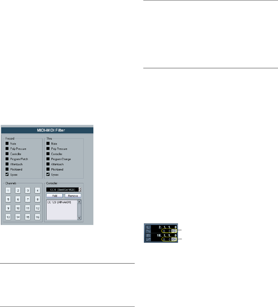
59
Recording
•Solo Record in MIDI Editors
If this is activated and you open a part for editing in a MIDI editor, its track
is automatically record-enabled. Furthermore, Record Enable is deacti-
vated for all other MIDI tracks until you close the editor again.
This makes it easier to record MIDI data when you’re editing a part – you
will always be sure the recorded data ends up in the edited part and not
on any other track.
•MIDI Record Catch Range in ms
When you record starting at the left locator, this setting helps you make
sure the very start of the recording is included. A very annoying scenario is
when you have recorded a perfect MIDI take, only to find out that the very
first note was not included – because you started playing a little bit too
early! If you raise the Record Catch Range, Cubase AI will catch the events
played just before the recording start point, eliminating this problem.
For a description of the other options, click the Help but-
ton in the Preferences.
Filtering MIDI
The MIDI–MIDI Filter page in the Preferences allows you
to prevent certain MIDI messages from being recorded
and/or “thruput” (echoed by the MIDI Thru function).
The dialog is divided into four sections:
Options and Settings
Recording-related Transport Preferences
A couple of settings in the Preferences (Transport page)
are relevant for recording. Set these according to your
preferred method of work:
Deactivate Punch In on Stop
If this is activated, punch in on the Transport panel is auto-
matically deactivated whenever you enter Stop mode.
Stop after Automatic Punch Out
If this is activated, playback will automatically stop after
automatic punch out (when the project cursor reaches the
right locator and punch out is activated on the Transport
panel). If the post-roll value on the Transport panel is set
to a value other than zero, playback will continue for the
set time before stopping (see below).
About Pre-roll and Post-roll
The pre-roll and post-roll value fields (below the left/right
locator fields) on the Transport panel have the following
functionality:
•By setting a pre-roll value, you instruct Cubase AI to
“roll back” a short section whenever playback is activated.
This applies whenever you start playback, but is perhaps most relevant
when recording from the left locator (punch in activated on the Transport
panel) as described below.
Section Description
Record Activating any of these options prevents that type of MIDI
message from being recorded. It can, however, be thru-
put, and if already recorded, it will play back normally.
Thru Activating any of these options prevents that type of MIDI
message from being thruput. It can, however, be recorded
and played back normally.
Channels If you activate a channel button, no MIDI messages on
that MIDI channel will be recorded or thruput. Already re-
corded messages will, however, be played back normally.
Controller Allows you to prevent certain MIDI controller types from
being recorded or thruput.
To filter out a controller type, select it from the list at the
top of the Controller section and click “Add”. It will ap-
pear on the list below.
To remove a controller type from the list (allow it to be re-
corded and thruput), select it in the lower list and click
“Remove”.
Section Description
Post-roll value field and on/off switch.
Pre-roll value field and on/off switch.
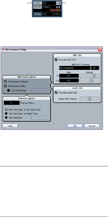
60
Recording
•By setting a post-roll value, you instruct Cubase AI to
play back a short section after automatic punch out before
stopping.
This is only relevant when punch out is activated on the Transport panel
and “Stop after Automatic Punch Out” is activated in the Preferences
(Transport page).
•To turn pre-roll or post-roll on or off, click the corre-
sponding button on the Transport panel (next to the pre/
post-roll value) or use the “Use Pre-roll” and “Use Post-
roll” options on the Transport menu.
An example:
1. Set the locators to where you want to start and end re-
cording.
2. Activate Punch in and Punch out on the Transport
panel.
3. Activate the option “Stop after Automatic Punch Out”
in the Preferences (Transport page).
4. Set suitable pre-roll and post-roll times by clicking in
the corresponding fields on the Transport panel and typ-
ing in time values.
5. Activate pre-roll and post-roll by clicking the buttons
next to the pre-roll and post-roll times so that they light up.
6. Activate recording.
The project cursor “rolls back” by the time specified in the pre-roll field
and playback starts. When the cursor reaches the left locator, recording
is automatically activated. When the cursor reaches the right locator, re-
cording is deactivated, but playback continues for the time set in the
post-roll field before stopping.
Using the metronome
The metronome can output a click that can be used as a
timing reference. The two parameters that govern the tim-
ing of the metronome are tempo and time signature, as set
in the Tempo Track Editor (see “Editing the tempo curve”
on page 223).
You can use the metronome for a click during recording
and/or playback or for a precount (count-in) that will be
heard when you start recording from Stop mode. Click
and precount are activated separately:
•To activate the metronome, click the Click button on the
Transport panel.
You can also activate the “Metronome On” option on the Transport menu
or use the corresponding key command (by default [C]).
•To activate the precount, click the Precount button on
the Transport panel.
You can also activate the “Precount On” option on the Transport menu
or set up a key command for this.
Metronome settings
You make settings for the metronome in the Metronome
Setup dialog, opened from the Transport menu.
The metronome can use either an audio click played back
via the audio hardware, send MIDI data to a connected
device which will play back the click or do both.
The following metronome settings can be made in the
dialog:
Metronome
Options Description
Metronome in
Record / Play Allows you to specify whether the metronome should be
heard during playback, recording or both (when Click is
activated on the Transport panel).
Use Count
Base If this option is activated, a field appears to the right where
you specify the “rhythm” of the metronome. Normally, the
metronome plays one click per beat, but setting this to e.g.
“1/8” gives you eighth notes – two clicks per beat. It is
also possible to create unusual metronome rhythms such
as triplets etc.
Click on/off Precount on/off
61
Recording
Recovery of audio recordings after
system failure
Normally, when a computer crashes, all changes made to
your current project since you last saved it will be lost. Usu-
ally, there is no quick and easy way to recover your work.
With Cubase AI, when your system crashes while you are
recording (because of a power cut or other mishap), you
will find that your recording is still available, from the mo-
ment when you started recording to the time when your
computer crashed.
When you experience a computer crash during a record-
ing, simply relaunch the system and check the project
record folder (by default this is the Audio subfolder inside
the project folder). It should contain the audio file you
were recording at the time of the crash.
Precount
Options Description
Precount Bars Sets the number of bars the metronome will count in be-
fore it starts recording if precount is activated on the
Transport panel.
Use Time
Signature at
Record Start
Time
When this is activated, the precount will automatically
use the time signature and tempo set at the position
where you start recording.
Use Time
Signature at
Project Time
When this is activated, the precount will be in the time
signature set on the tempo track. Furthermore, any tempo
changes on the tempo track during the precount will be
applied.
Use Signature This lets you set a time signature for the precount. In this
mode, tempo changes on the tempo track will not affect
the precount.
MIDI Click Description
Activate MIDI
Click Selects whether or not the metronome will sound via
MIDI.
MIDI Port/
Channel This is where you select a MIDI output and channel for the
metronome click. Note that you can select a VST Instru-
ment previously set up in the VST Instruments window
from this menu, allowing you to use a VST Instrument
sound for the Metronome click.
Hi Note/
Velocity Sets the MIDI note number and velocity value for the
“high note” (the first beat in a bar).
Lo Note/
Velocity Sets the MIDI note number and velocity for the “low
notes” (the other beats).
Audio Click Description
Activate
Audio Click Selects whether or not the metronome will sound via the
audio hardware. You can set the level of the click with the
slider.
!
This feature does not constitute an “overall” guaran-
tee by Steinberg. While the program itself was im-
proved in such a way that audio recordings can be
recovered after a system failure, it is always possible
that a computer crash, power cut, etc. might have
damaged another component of the computer, mak-
ing it impossible to save or recover any of the data.
!
Please do not try to actively bring about this kind of
situation to test this feature. Although the internal
program processes have been improved to cope
with such situations, Steinberg cannot guarantee
that other parts of the computer are not damaged as
a consequence.
6
Fades, crossfades and envelopes
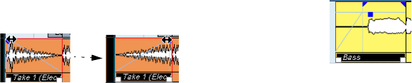
63
Fades, crossfades and envelopes
Creating fades
There are two main types of fade-ins and fade-outs in au-
dio events in Cubase AI: fades created by using the fade
handles (see below) and fades created by processing
(see “Fades created by processing” on page 64).
Fades created by using the fade handles
Selected audio events have blue handles in the upper left
and right corners. These can be dragged to create a fade-
in or fade-out respectively.
Creating a fade-in. The fade is automatically reflected in the shape of
the event’s waveform, giving you a visual feedback of the result when
you drag the fade handle.
Fades created with the handles are not applied to the au-
dio clip as such but calculated in realtime during playback.
This means that several events referring to the same audio
clip can have different fade curves. It also means that hav-
ing a huge number of fades may demand a lot of processor
power.
•If you select multiple events and drag the fade handles
on one of them, the same fade will be applied to all se-
lected events.
•A fade can be edited in the Fade dialog, as described
on the following pages.
You open the dialog by double-clicking in the area above the fade curve,
or by selecting the event and selecting “Open Fade Editor(s)” from the
Audio menu (note that this will open two dialogs if the event has both
fade-in and fade-out curves).
If you adjust the shape of the fade curve in the Fade dialog, this shape
will be maintained when you later adjust the length of a fade.
•You can make the fade longer or shorter at any time, by
dragging the handle.
You can actually do this even without selecting the event first, i.e. without
visible handles. Just move the mouse pointer along the fade curve until
the cursor turns into a bidirectional arrow, then click and drag.
•If the option “Fade Handles always on Top” is activated
in the Preferences dialog (Event Display–Audio page), the
fade handles stay at the top of the event, and vertical help
lines indicate the exact end or start points of fades.
This is useful in situations where you want the event volume to be very
low, as this option allows you to still see the fade handles.
•If the option “Show Event Volume Curves Always” is ac-
tivated in the Preferences (Event Display–Audio page), the
fade curves will be shown in all events, regardless of
whether they are selected or not.
If the option is deactivated, the fade curves are shown in selected events
only.
•If the option “Thick Fade Lines” is activated in the Prefer-
ences dialog (Event Display–Audio page), the fade lines
and volume curve are thicker, increasing their visibility.
Fade handles on top of the event and thicker fade and volume lines al-
low you to edit and view fades even in situations where event volume is
very low.
•When the option “Use Mouse Wheel for Event volume
and Fades” is activated in the Preferences dialog (Edit-
ing–Audio page), you can use the mouse wheel to move
the volume curve up or down. When you hold down [Shift]
while moving the mouse wheel, this will change the fade
curves. This is useful in situations where the fade handles
are not visible (e.g. because of a very high zoom factor).
When you position the mouse pointer somewhere in the left half of the
event, the fade in end point is moved. When the mouse pointer is in the
right half of the event, the fade out start point will move.
ÖYou can set up key commands for changing the event
volume curve and any fade curves, if you do not want to
use the mouse for this.
You will find these commands in the Key Commands dialog, in the Audio
category, see “Key commands” on page 268.
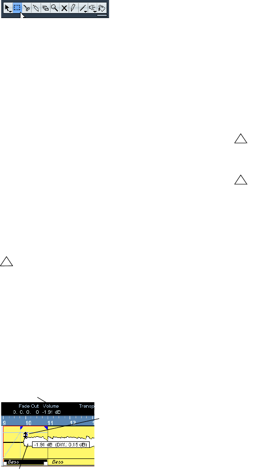
64
Fades, crossfades and envelopes
Creating and adjusting fades with the Range Selection
tool
“Handle-type” fades can also be created and adjusted
with the Range Selection tool, in the following way:
1. Select a section of the audio event with the Range Se-
lection tool.
The result depends on your selection:
• If you select a range from the beginning of the event, a fade-in
will be created within the range.
• If you select a range that reaches the end of an event, a fade-
out will be created in the range.
• If you select a range encompassing a middle section of the
event, but not reaching neither the start nor the end, both a
fade-in and a fade-out will be created outside of the selected
range. In other words, the fade-in will cover the area from the
beginning of the event to the beginning of the selected range,
and the fade-out will cover the area from the end of the se-
lected range to the end of the event.
2. Pull down the Audio menu and select “Adjust Fades to
Range”.
The fade areas are adjusted according to the selection range.
About the volume handle
A selected audio event also has a blue handle in the top
middle. This is the volume handle, and it provides a quick
way of changing the volume of an event, directly in the
Project window. It is linked directly to the volume setting
on the info line, that is, dragging the volume handle also
changes the value on the info line.
Removing fades
To remove the fades for an event, select the event and se-
lect “Remove Fades” from the Audio menu.
You can also use the Range Selection tool to remove
fades and crossfades within the selected range this way.
Fades created by processing
If you have selected an audio event or a section of an au-
dio event (using the Range Selection tool), you can apply
a fade-in or fade-out to the selection by using the “Fade
In” or “Fade Out” functions on the Process submenu on
the Audio menu. These functions open the corresponding
Fade dialog, allowing you to specify a fade curve.
Fades created this way are applied to the audio clip rather
than to the event. Please note the following:
• If you later create new events that refer to the same clip, these
will have the same fades.
If other events refer to the same audio clip, you will be
asked whether you want the processing to be applied to
these events or not.
• Continue will apply the processing to all events that refer to
the audio clip.
• New Version will create a separate, new version of the audio
clip for the selected event.
•You can also activate the option “Do not show this mes-
sage again”. Regardless of whether you then choose “Con-
tinue” or “New Version”, any further processing will conform
to the option you select.
You can change this setting at any time in the Preferences (Editing–Audio
page), under “On Processing Shared Clips”.
!
You can select multiple audio events on separate
tracks with the Range Selection tool, and apply the
fade to all of them simultaneously.
Drag the Volume handle
up or down to change the
volume of the event.
The volume change is displayed numerically on the info line.
The event waveform reflects the volume change.
!
Note that the length of the fade area is determined
by your selection. In other words, you specify the
length of the fade before you enter the Fade dialog.
!
Also note that you can select multiple events and ap-
ply the same processing to all of them simultaneously.
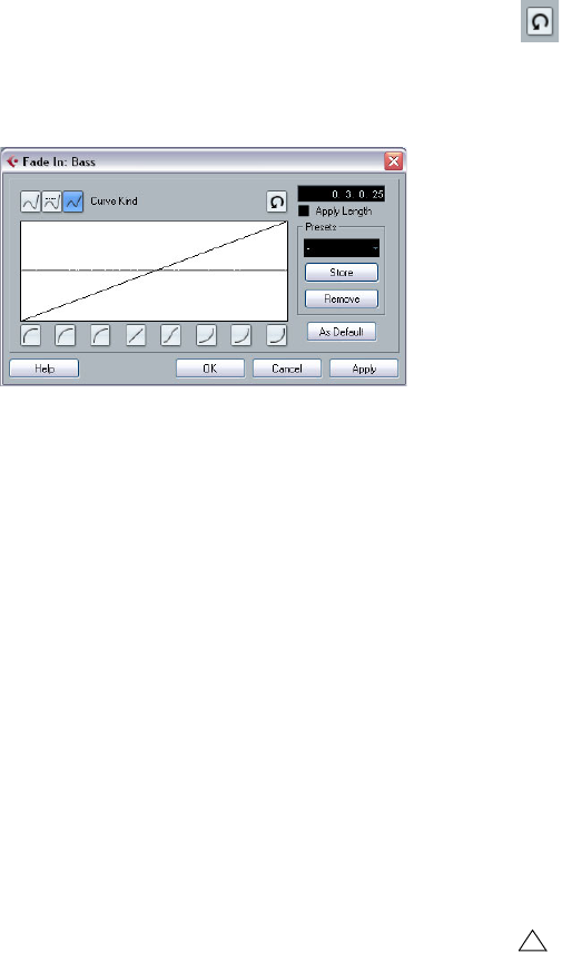
65
Fades, crossfades and envelopes
The Fade dialogs
The Fade dialogs appear when you edit an existing fade or
use the Fade In/Fade Out functions on the Process sub-
menu on the Audio menu. The picture below shows the
Fade In dialog; the Fade Out dialog has identical settings
and features.
•If you open the Fade dialog(s) with several events se-
lected, you can adjust the fade curves for all these events
at the same time.
This is useful if you want to apply the same type of fade-in to more than
one event, etc.
Curve Kind
These buttons determine whether the fade curve should
consist of spline curve segments (left button), damped
spline segments (middle button) or linear segments (right
button).
Fade display
The Fade display shows the shape of the fade curve. The
resulting waveform shape is shown in dark gray, with the
current waveform shape in light gray.
You can click on the curve to add points, and click and
drag existing points to change the shape. To remove a
point from the curve, drag it outside the display.
Curve shape buttons
These buttons give you quick access to some common
curve shapes.
Restore button
The Restore button (to the right above the fade display) is
only available when editing fades made by dragging the
fade handles. Click this to cancel any changes you have
made since opening the dialog.
As Default button
The “As Default” button is only available when editing
fades made by dragging the fade handles. Click this to
store the current settings as the default fade. This shape
will be used whenever you create new fades.
Fade Length Value
The Fade Length Value is only available when editing fades
made by dragging the fade handles. It can be used to enter
fade lengths numerically. The format of values displayed
here are determined by the Time Display in the Transport
Panel.
When you activate the “Apply Length” option, the value en-
tered in the Fade Length value field will be used when click-
ing “Apply” or “OK”. This setting is deactivated by default.
When you set the current Fade as the Default fade, the
length value is included as part of the default settings.
Presets
If you have set up a fade in or fade out curve that you may
want to apply to other events or clips, you can store it as a
preset by clicking the Store button.
•To apply a stored preset, select it from the pop-up menu.
•To rename the selected preset, double-click on the
name and type a new one.
•To remove a stored preset, select it from the pop-up
menu and click Remove.
!
Stored fade in presets will only appear in the Fade In
dialog, and fade out presets will only appear in the
Fade Out dialog.
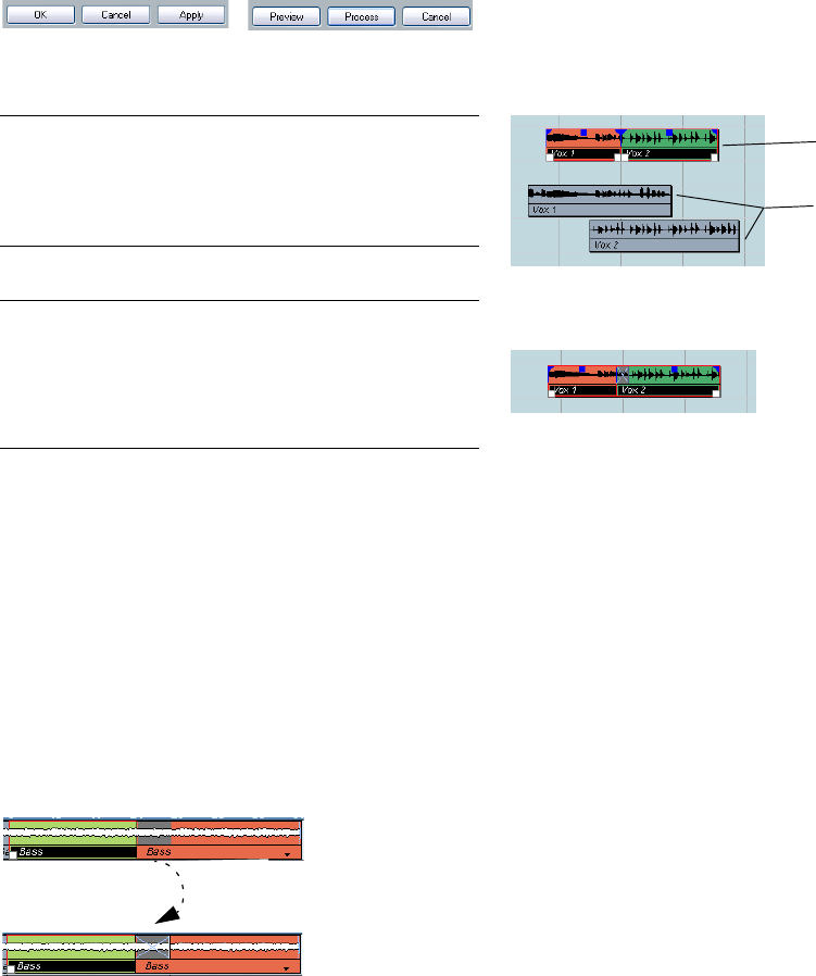
66
Fades, crossfades and envelopes
Preview, Apply and Process
The buttons in the bottom row are different depending on
whether you are editing a fade made with the fade handles
or applying a fade using processing:
The Edit Fade dialogs have the following buttons:
The Process Fade dialogs have the following buttons:
Creating crossfades
Overlapping audio material on the same track can be cross-
faded, for smooth transitions or special effects. You create
a crossfade by selecting two consecutive audio events and
selecting the Crossfade command on the Audio menu (or
by using the corresponding key command, by default [X]).
The result depends on whether the two events overlap or
not:
•If the events overlap, a crossfade is created in the over-
lapping area.
The crossfade will be of the default shape – initially a linear, symmetric
crossfade, but you can change this as described below.
•If the events do not overlap but are directly consecutive
(lined up end-to-start, with no gap) it is still possible to
crossfade them – provided that their respective audio
clips overlap! In this case, the two events are resized so
that they overlap, and a crossfade of the default length
and shape is applied.
The default crossfade length and shape are set in the Crossfade dialog
(see “Default buttons” on page 68).
An example:
The events themselves do not overlap, but their clips do. Therefore, the
events can be resized so that they overlap, which is required for a cross-
fade to be created.
When you select the Crossfade function, the two events are resized so that
they overlap, and a default crossfade is created in the overlapping section.
•If the events do not overlap, and cannot be resized
enough to overlap, a crossfade cannot be created.
•Once you have created a crossfade, you can edit it by
selecting one or both crossfaded events, and selecting
“Crossfade” from the Audio menu again (or by double-
clicking in the crossfade zone).
This opens the Crossfade dialog, see below.
Removing crossfades
To remove a crossfade, proceed as follows:
•Select the events and select “Remove Fades” from the
Audio menu.
You can also use the Range Selection tool: drag the Range Selection
tool so that the selection encloses all the fades and crossfades you wish
to remove, and select “Remove Fades” from the Audio menu.
•You can also remove a crossfade by clicking and drag-
ging it outside the track.
Button Function
OK Applies the set fade curve to the event, and closes the dialog.
Cancel Closes the dialog.
Apply Applies the set fade curve to the event, without closing the
dialog.
Button Function
Preview Plays back the fade area. Playback will repeat until you click
the button again (the button is labeled “Stop” during play-
back).
Process Applies the set fade curve to the clip, and closes the dialog.
Cancel Closes the dialog without applying any fade.
The Edit Fade dialog The Process Fade dialog
Overlapping
section
Audio clips
Audio events
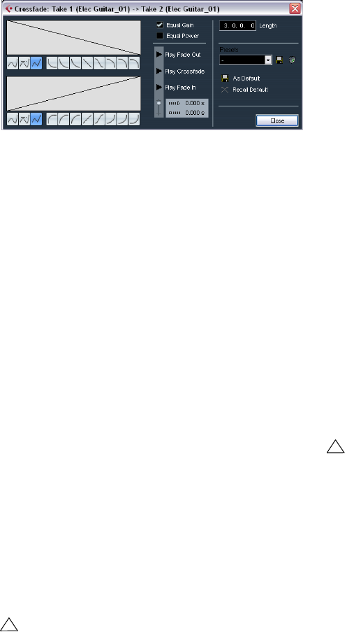
67
Fades, crossfades and envelopes
The Crossfade dialog
The Crossfade dialog contains separate, but identical,
sections for the fade-in and fade-out curve settings in the
crossfade on the left, and common settings on the right.
Fade Displays
Shows the shape of the fade-out and fade-in curve, re-
spectively. You can click on the curve to add points, and
click and drag existing points to change the shape. To re-
move a point from the curve, drag it outside the display.
Curve kind buttons
These buttons determine whether the corresponding fade
curve should consist of spline curve segments (left but-
ton), damped spline segments (middle button) or linear
segments (right button).
Curve shape buttons
These buttons give you quick access to some common
curve shapes.
Equal Power and Gain
•If you activate the “Equal Gain” checkbox, the fade
curves are adjusted so that the summed fade-in and fade-
out amplitudes will be the same all along the crossfade
region. This is often suitable for short crossfades.
•If you activate the “Equal Power” checkbox, the fade
curves are adjusted, so that the energy (power) of the
crossfade will be constant all along the crossfade region.
Play buttons
•The “Play Fade Out” and “Play Fade In” buttons allow
you to audition the fade-out or fade-in part only, without
the crossfade.
•The “Play Crossfade” button plays back the whole
crossfade.
You can also use the Transport panel controls to play back
the crossfaded audio events. However, that method will
play back all unmuted audio events on other tracks as well.
Pre-roll and Post-roll
When auditioning with the Play buttons, you can choose
to activate pre-roll and/or post-roll. Pre-roll lets you start
playback before the fade area, and post-roll lets you stop
playback after the fade area. This can be useful for audi-
tioning the fade in a context.
•To specify how long the pre-roll and post-roll should be,
click in the time fields and enter the desired time (in sec-
onds and milliseconds).
•To activate pre-roll and post-roll, click the respective
button. To deactivate it, click the button again.
Length settings
You can adjust the length of the crossfade area numeri-
cally in the “Length” field. If possible, the length change
will be applied equally to “both sides” of the crossfade
(i.e. Cubase AI tries to “center” the crossfade).
Presets
If you have set up a crossfade shape that you may want to
apply to other events, you can store it as a preset by click-
ing the Store button.
•To apply a stored preset, select it from the pop-up menu.
•To rename the selected preset, double-click on the
name and type in a new one.
•To remove a stored preset, select it from the pop-up
menu and click Remove.
!
Equal Power curves have only one editable curve
point. You cannot use the Curve kind buttons or the
presets when this mode is selected.
!
To be able to resize a crossfade this way, it must be
possible to resize the corresponding event. For ex-
ample, if the left crossfaded event already plays its
audio clip to the end, its endpoint cannot be moved
any further to the right.
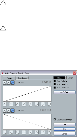
68
Fades, crossfades and envelopes
Default buttons
•Clicking the “As Default” button stores all of the current
settings as the default crossfade. These settings will then
be used whenever you create new crossfades.
•The Crossfade Length setting is included in the Default
settings. However, it is only applied if the events to be
crossfaded do not overlap, otherwise the crossfade will be
in the overlap area (see “Creating crossfades” on page 66).
•Clicking the “Recall Default” button copies the curves
and settings of the Default crossfade to the Crossfade
dialog.
Auto Fades and Crossfades
Cubase AI features an Auto Fade function that can be set
both globally, i.e. for the entire project, and separately for
each audio track. The idea behind the Auto Fade function
is to create smoother transitions between events by ap-
plying short (1–500ms) fade-ins and fade-outs.
Making global Auto Fade settings
1. To make Auto Fades settings globally for the project,
select “Auto Fades Settings…” from the Project menu.
This opens the Auto Fades dialog for the project.
2. Use the checkboxes in the upper right corner to acti-
vate or deactivate Auto Fade In, Auto Fade Out and Auto
Crossfades, respectively.
3. Use the Length value field to specify the length of the
Auto Fade or Crossfade (1–500ms).
4. To adjust the shapes of Auto Fade In and Auto Fade
Out, select the “Fades” tab and make settings as in the
regular Fade dialogs.
5. To adjust the shape of the Auto Crossfade, select the
“Crossfades” tab and make settings as in the regular
Crossfade dialog.
6. If you want to use the settings you have made in future
projects, click the “As Default” button.
The next time you create a new project, it will use these settings by default.
7. Click OK to close the dialog.
Making Auto Fade settings for a separate track
By default, all audio tracks will use the settings you have
made in the project’s Auto Fades dialog. However, since
Auto Fades use computing power, a better approach may
be to turn Auto Fades off globally and activate them for in-
dividual tracks, as needed:
1. Right-click the track in the Track list and select “Auto
Fades Settings…” from the context menu (or select the
track and click the “Auto Fades Settings” button in the In-
spector).
The Auto Fades dialog for the track opens. This is identical to the project’s
Auto Fades dialog, with the addition of a “Use Project Settings” option.
2. Deactivate the “Use Project Settings” option.
Now, any settings you make will be applied to the track only.
3. Set up the Auto Fades as desired and close the dialog.
Reverting to project settings
If you want a track to use the global Auto Fade settings,
open the Auto Fades dialog for the track and activate the
“Use Project Settings” checkbox.
!
As mentioned earlier, fades are calculated in realtime
during playback. This means that the larger the num-
ber of audio tracks with Auto Fades activated in a
project, the higher the demands on the processor.
!
Note that auto fades are not indicated by the fade
lines!
7
The mixer
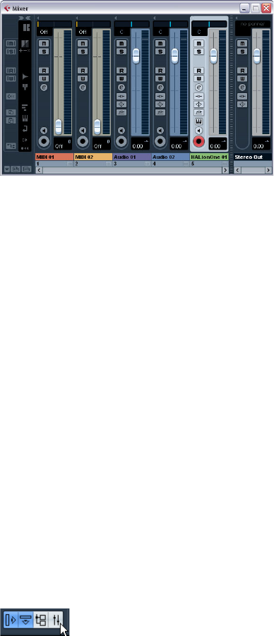
70
The mixer
About this chapter
This chapter contains detailed information about the ele-
ments used when mixing audio and MIDI, and the various
ways you can configure the mixer.
Some mixer-related features are not described in this
chapter. These are the following:
•Setting up and using audio effects.
See the chapter “Audio effects” on page 85.
•Automation of all mixer parameters.
See the chapter “Automation” on page 108.
•How to mix down several audio tracks (complete with
automation and effects if you wish) to a single audio file.
See the chapter “Export Audio Mixdown” on page 226.
Overview
The mixer offers a common environment for controlling
levels, pan, solo/mute status etc. for both audio and MIDI
channels.
Opening the mixer
The mixer can be opened in several ways:
•By selecting Mixer from the Devices menu.
•By clicking the Mixer icon on the toolbar.
•By using a key command (by default [F3]).
•By clicking the Mixer button in the Devices panel.
You open the Devices panel by selecting Show Panel from the Devices
menu.
What channel types can be shown in the mixer?
The following track-based channel types are shown in the
mixer:
•Audio
•MIDI
• Effect return channels (referred to as FX channels in the
Project window)
• Group channels
• Instrument track channels
The order of audio, MIDI, instrument, group and effect re-
turn channel strips (from left to right) in the mixer corre-
sponds to the Project window Track list (from the top
down). If you reorder tracks of these types in the Track list,
this will be mirrored in the mixer.
In addition to the above, the following channel types are
also shown in the mixer:
• VST Instrument channels (see the chapter “VST Instruments
and Instrument tracks” on page 99).
The other track types are not shown in the mixer.
Output busses in the mixer
Output busses are represented by output channels in the
mixer. They appear in a separate “pane” separated by a
movable divider and with its own horizontal scrollbar, see
“The output channels” on page 74.
Configuring the mixer
The mixer window can be configured in various ways to
suit your needs and to save screen space. Here follows a
run through of the various view options (the following de-
scriptions assume that you have an active project contain-
ing some tracks).
The mixer shows the channel faders for the various tracks
of your project. On the right of the fader panel you find the
output channel fader. On the left is the common panel
which allows for global settings affecting all channels.
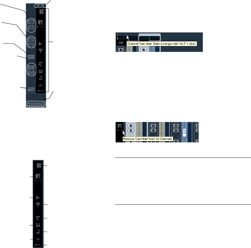
71
The mixer
The common panel
The common panel appears to the left in the mixer window
and contains settings for changing the look and behavior of
the mixer, as well as global settings for all channels.
Selecting what channel types to show/hide
You can specify what channel types to show or hide in the
mixer. In the lower part of the common panel you find a
vertical strip with different indicator buttons. Each indica-
tor represents a channel type to show or hide in the mixer:
•To hide or show a channel type, click the corresponding
indicator.
If an indicator is dark, the corresponding channel type will be shown in
the mixer. If it is orange, the corresponding channel type will be hidden.
Showing/hiding individual channels
(the “Can Hide” setting)
You can also show/hide individual channels of any type in
the mixer. For this, you can assign channels a “Can Hide”
status, which allows you to hide these channels collec-
tively. Proceed as follows:
1. [Alt]/[Option]-click in the top middle section of the
channel strip activate the “Can Hide” option.
The “/” icon is shown if “Can Hide” is activated for a channel strip.
2. Repeat this for all channels you want to hide.
3. Click the button “Hide Channels set to ‘Can Hide’” on
the common panel.
This hides all channels set to “Can Hide”. To show them again, click the
button again or click the “Reveal All Channels” button at the bottom of
the common panel.
Below the “Hide Channels set to ‘Can Hide’” button, there
are three additional buttons.
These have the following functionality:
Global automation Read/
Write buttons
Store/Remove View set
buttons (+/-) and Select
View set pop-up, see
“Channel view sets” on
page 72.
With these indicator but-
tons you can select which
channel types are shown
in the mixer (see “Selec-
ting what channel types to
show/hide” on page 71)
and/or will be affected by
commands (see “About
the Command Target” on
page 72).
Toggle channel strips in the
mixer between “All Targets
Wide” and “All Targets Nar-
row”.
Opens the VST Connec-
tions window, see “The
VST Connections win-
dow” on page 11.
Reset Mixer/
Reset Channels
Channel settings copy/
paste, see “Copying set-
tings between audio
channels” on page 79.
Global Mute and
Solo buttons
Audio Channels
Group Channels
MIDI Channels
VST Instrument Channels
FX Channels
Output Channels
“Can Hide” options,
see below
Reveal all channels
“Command Target” options –
see “About the Command
Target” on page 72.
Option Description
Set Target Channels
to ‘Can Hide’ This activates “Can Hide” for all Channels you
specified as “Command Targets”, see below.
Remove ‘Can Hide’
from Target Channels This deactivates “Can Hide” for all Channels you
specified as “Command Targets”, see below.
Remove ‘Can Hide’
from All Channels This deactivates “Can Hide” for all Channels in the
Mixer.
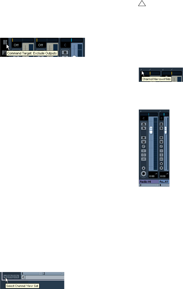
72
The mixer
About the Command Target
Command targets let you specify which channels should
be affected by the “commands” (basically all the functions
that can be assigned key commands) when working with
the Mixer, e.g. the width setting of the channel strips, etc.
You can set command targets using the Mixer common
panel or the context menu.
The Command Target Controls on the common panel
The following options are available:
• All Channels – Select this if you want your commands to af-
fect all channels.
• Selected Only – Select this if you want your commands to af-
fect the selected channels only.
• Exclude Outputs – Select this if you do not want your com-
mands to affect the output channels.
Channel view sets
Channel view sets are saved configurations of the mixer
window, allowing you to quickly switch between different
layouts for the mixer. Proceed as follows:
1. Set up the mixer the way you wish to store it as a view
set.
The following settings will be stored:
• Settings for individual channel strips (e.g. narrow or wide mode
and whether the channel strip is (or can be) hidden or not).
• The hide/show status for channel types.
2. Click the “Store View Set” button (the plus sign) at the
bottom of the common panel.
3. A dialog appears, allowing you to enter a name for the
view set.
4. Click OK to store the current mixer view set.
•You can now return to this stored configuration at any
time, by clicking the “Select Channel View Set” button
(the down arrow to the left of the “Store View Set” button)
and selecting it from the pop-up menu.
•To remove a stored channel view set, select it and click
the “Remove View Set” button (the minus sign).
Setting the width of channel strips
Each channel strip can be set to either “Wide” or “Narrow”
mode by using the Channel Narrow/Wide button on the left
above the fader strip.
The Channel Narrow/Wide button
•Narrow channel strips contain a narrow fader, miniature
buttons, and the View options pop-up.
Wide and narrow channel strips
•When selecting “All targets narrow” or “All targets
wide” on the common panel, all channel strips selected as
command targets (see “About the Command Target” on
page 72) are affected.
!
Some remote control devices (such as Steinberg’s
Houston) feature this function, which means that you
can use the remote device to switch between the
channel view sets.
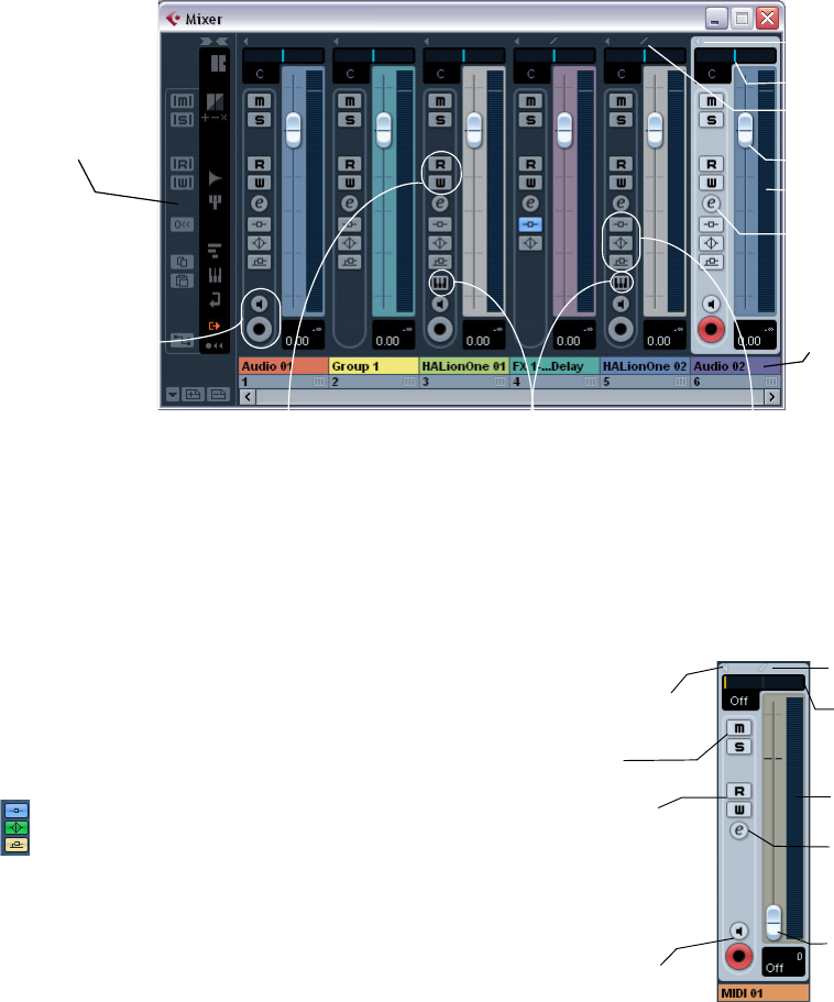
73
The mixer
The audio-related channel strips
All audio-related channel types (audio, instrument track,
output channels, group, effect return, VST Instrument) ba-
sically have the same channel strip layout, with the follow-
ing differences:
• Only audio and instrument track channels have a Monitor and
Record Enable button.
• Output channels do not have sends.
• Instrument track and VST Instrument channels have an addi-
tional button for opening the instrument’s control panel.
• Output channels have clipping indicators.
About the Insert/EQ/Send indicators and bypass buttons
The three indicator buttons in each audio channel strip
have the following functionality:
•If an Insert or Send effect or an EQ module is activated
for a channel, the corresponding button is lit.
The effect indicators will be blue, the EQ indicator will be green.
•If you click these buttons when lit, the corresponding
EQ or effects section will be bypassed.
Bypass is indicated by yellow buttons. Clicking the button again deacti-
vates bypass.
The MIDI channel strips
The MIDI channel strips allow you to control volume and
pan in your MIDI instrument (provided that they are set up to
receive the corresponding MIDI messages). The settings
here are also available in the Inspector for MIDI tracks.
The common
panel (see “The
common panel”
on page 71)
Channel automation controls
Record Enable
and Monitor
buttons
Opens the control panel for the
VST Instrument
Level meter
Level fader
Edit button (opens
the Channel Settings
window)
Insert/EQ/Send indicators and bypass
buttons (see below)
Channel name
The Can Hide State for
the channel
Narrow/Wide button
Pan control
Level fader
(MIDI volume)
Level (velocity) meter
Channel automation
controls
Pan control
Monitor and Record
Enable buttons
Edit button
Mute and Solo
Channel Narrow/Wide
button
Can Hide State
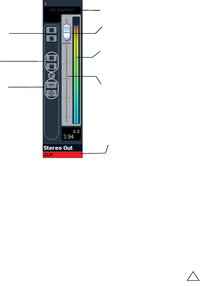
74
The mixer
The output channels
The output busses you set up in the VST Connections
window are represented by output channels in the mixer.
They are shown in a separate “pane” (to the right of the
regular channel strips), with its own divider and horizontal
scrollbar. The output channel strip is very similar to other
audio channels.
•For information on how to set up input and output bus-
ses, see the chapter “VST Connections: Setting up input
and output busses” on page 9.
•How to route audio channels to busses is described in
the section “The output channels” on page 74.
•The Main Mix (the default output) bus is used for moni-
toring. For information about Monitoring, see “About moni-
toring” on page 13.
Basic mixing procedures
Setting volume in the mixer
In the mixer, each channel strip has a volume fader.
•For audio channels, the faders control the volume of the
channels before they are routed (directly or via a group)
channel to an output bus.
•An output channel fader determines the master output
level of all audio channels routed to that output bus.
•MIDI channels handle fader volume changes in the mixer
by sending out MIDI volume messages to the connected in-
strument(s).
Connected instruments must be set to respond to MIDI messages (such
as MIDI volume in this case) for this to function properly.
•The fader settings are displayed numerically below the
faders, in dB for audio channels and in the MIDI volume 0
to 127 value range for MIDI channels.
You can click in the fader value fields and enter a volume setting by typing.
•To make fine volume adjustments, hold down [Shift]
when you move the faders.
•If you hold down [Ctrl]/[Command] and click on a fader,
it will be reset to its default value, i.e. 0.0dB for audio
channels, or MIDI volume 100 for MIDI channels.
This reset to default values works for most mixer parameters.
You can use the faders to set up a volume balance be-
tween the audio and MIDI channels and perform a manual
mix by moving the faders and other controls while playing
back. By using the Write function (see “Enabling and
disabling the writing of automation data” on page 109),
you can automate the levels and most mixer actions.
Bus level meter
Read/Write
Automation
Clipping indicator, see
“Setting input levels”
on page 52.
Edit button
Inserts and EQ
indicators and
Bypass buttons
Pan control
Mute and Solo
buttons
Bus volume fader
!
It is also possible to make static volume settings for
an event on the info line or with the volume handle
(see “About the volume handle” on page 64).
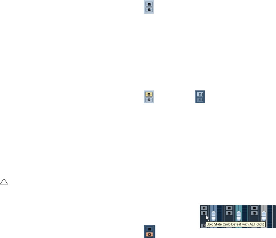
75
The mixer
About the level meters for audio channels
When playing back audio in Cubase AI, the level meters in
the mixer show the level of each audio channel.
•Directly below the level meter is a small level readout –
this shows the highest registered level in the signal.
Click this to reset the peak levels.
If the peak level of the audio goes above 0dB, the numer-
ical level indicator will show a positive value (i.e. a value
above 0dB).
ÖCubase AI uses 32 bit floating point processing inter-
nally, so there is virtually limitless headroom – signals can
go way beyond 0dB without clipping. Having higher levels
than 0dB for individual audio channels is therefore not a
problem in itself. The audio quality will not be degraded by
this.
However, when many high level signals are mixed in an output bus, this
may require that you lower the output channel level a lot (see below).
Therefore it is good practice to keep the maximum levels for individual
audio channels roughly around 0dB.
About the level meters for output channels
For the output channels, things are different. These chan-
nels have clipping indicators.
•When you are recording, clipping can occur when the
analog signal is converted to digital in the audio hardware.
It is also possible to get clipping in the signal being recorded to disk. For
more information, see “Setting input levels” on page 52.
•In the output busses, the floating point audio is converted
to the resolution of the audio hardware. In the integer audio
domain, the maximum level is 0dB – higher levels will cause
the clipping indicator for each bus to light up.
If the clipping indicators light up for a bus, this indicates actual clipping –
digital distortion which should always be avoided.
Level meters for MIDI channels
The level meters for MIDI channels do not show actual vol-
ume levels. Instead, they indicate the velocity values of the
notes played back on MIDI tracks.
MIDI tracks set to the same MIDI channel and output
If you have several MIDI tracks set to the same MIDI chan-
nel (and routed to the same MIDI output), making volume
and pan settings for one of these MIDI tracks/mixer chan-
nels will also affect all other mixer channels set to the
same MIDI channel/output combination.
Using Solo and Mute
The Mute and Solo buttons
You can use the Mute and Solo buttons to silence one or
several channels. The following applies:
•The Mute button silences the selected channel.
Clicking the Mute button again unmutes the channel. Several channels
can be muted simultaneously. Muting Group channels can have two dif-
ferent results depending on how the Preferences are set (see “Settings
for group channels” on page 80). A muted channel is indicated by a lit
Mute button and also by the lit Global Mute indicator on the common
panel.
•Clicking the Solo button for a channel mutes all other
channels.
A soloed channel is indicated by a lit Solo button, and also by the lit Glo-
bal Solo indicator on the common panel. Click the Solo button again to
turn off Solo.
•Several channels can be soloed at the same time.
However, if you press [Ctrl]/[Command] and click the Solo button for a
channel, any other soloed channels will automatically be un-soloed (i.e.
this Solo mode is exclusive).
•[Alt]/[Option]-clicking a Solo button activates “Solo De-
feat” for that channel.
In this mode the channel will not be muted if you solo another channel. To
turn off Solo Defeat, [Alt]/[Option]-click the Solo button again.
•You can un-mute or un-solo all channels by clicking the
Mute or Solo indicator on the common panel.
!
If the clipping indicator lights up for an output chan-
nel, reset the indicator by clicking on it, and lower the
level until the indicator does not light up.
A muted channel
in the mixer. A lit Global Mute indicator on the
common panel shows that one or
more channels are muted.
[Alt]/[Option]-click a Solo
button…
…to activate Solo Defeat for that channel.

76
The mixer
Setting pan in the mixer
The pan control
The pan controls in the mixer are used to position a chan-
nel between the left and right side of the stereo spectrum.
By default for stereo audio channels, pan controls the bal-
ance between the left and right channels. You can change
this in the Preferences. By selecting one of the other pan
modes (see below), you can set pan independently for the
left and right channel.
•To make fine pan adjustments, hold down [Shift] when
you move the pan control.
•To select the (default) center pan position, hold down
[Ctrl]/[Command] and click on the pan control.
•For MIDI channels, the pan control sends out MIDI pan
messages.
The result depends on how your MIDI instrument is set to respond to pan
– check your documentation for details.
About the “Stereo Pan Law” setting (audio channels only)
In the Project Setup dialog there is a pop-up menu named
“Stereo Pan Law”, on which you can select one of several
pan modes. This is related to the fact that without power
compensation, the power of the sum of the left and right
side will be higher (louder) if a channel is panned center
than if it is panned left or right.
To remedy this, the Stereo Pan Law setting allows you to
attenuate signals panned center, by -6, -4.5 or -3dB (de-
fault). Selecting the 0dB option effectively turns off con-
stant-power panning. Experiment with the modes to see
which fits best in a given situation. You can also select
“Equal Power” on this pop-up menu, which means that the
power of the signal will remain the same regardless of the
pan setting.
Audio-specific procedures
This section describes the options and basic procedures
regarding audio channels in the mixer.
Using Channel Settings
For each audio channel strip in the mixer and in the Inspec-
tor and Track list for each audio track, there is an Edit but-
ton (“e”).
Clicking this opens the VST Audio Channel Settings win-
dow. By default, this window contains:
• A section with eight insert effect slots (see “Audio effects” on
page 85).
• Four EQ modules and an associated EQ curve display (see
“Making EQ settings” on page 77).
• A section with eight sends (see “Audio effects” on page 85).
• A duplicate of the mixer channel strip
You can customize the Channel Settings window, by
showing/hiding the different panels and/or by changing
their order:
• To specify which panels should be shown/hidden, right-click
in the Channel settings window, and activate/deactivate the
respective options on the Customize View submenu on the
context menu.
• To change the order of the panels, select “Setup…” on the
Customize View pop-up menu and use the “Move up” and
“Move Down” buttons.
ÖFor further information, see the chapter “Customizing”
on page 261.
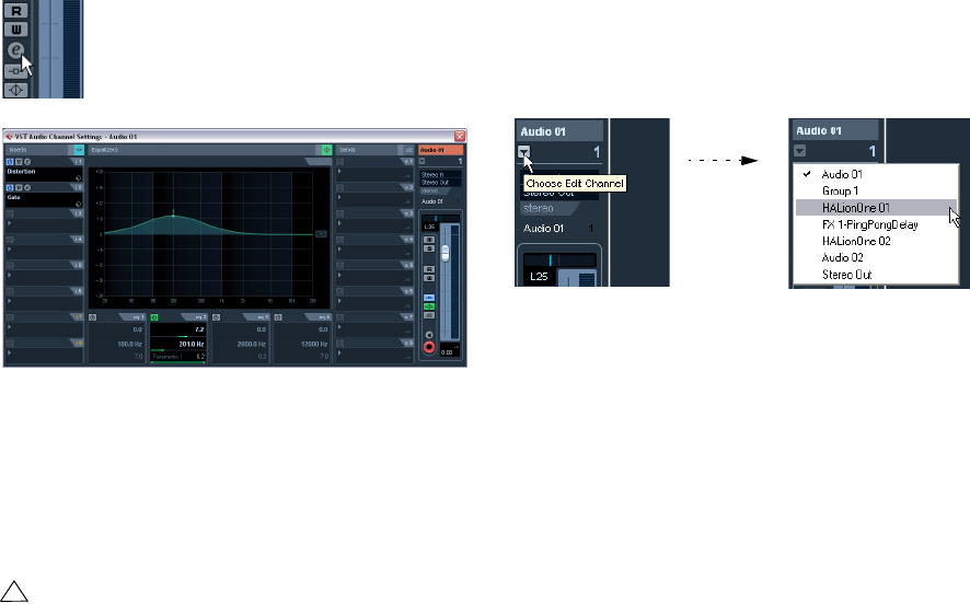
77
The mixer
Every channel has its own channel settings window (al-
though you can view each in the same window if you like –
see below).
The Channel Settings window is used for the following
operations:
• Apply equalization, see “Making EQ settings” on page 77.
• Apply send effects, see “Audio effects” on page 85.
• Apply insert effects, see “Audio effects” on page 85.
• Copy channel settings and apply them to another channel, see
“Copying settings between audio channels” on page 79.
Changing channels in the Channel Settings window
You can view any channel’s settings from a single window.
If the option “Sync Project and Mixer Selection” is acti-
vated in the Preferences (Editing–Project & Mixer page),
this can be done “automatically”:
•Open the Channel Settings window for a track and po-
sition it so that you can see both the Project window and
the Channel Settings window.
Selecting a track in the Project window automatically
selects the corresponding channel in the mixer (and vice
versa). If a Channel Settings window is open, this will im-
mediately switch to show the settings for the selected
channel. This allows you to have a single Channel Settings
window open in a convenient position on the screen, and
use it for all your EQ and channel effect settings.
You can also select a channel manually (thereby changing
what is shown in the open Channel Settings window).
Proceed as follows:
1. Open the Channel Settings window for any channel.
2. Open the Choose Edit Channel pop-up menu by
clicking the arrow button to the left of the channel number
at the top of the Fader view.
3. Select a channel from the pop-up to show the settings
for that channel in the open Channel Settings window.
•Alternatively, you can select a channel in the mixer by
clicking its channel strip (make sure not to click on a con-
trol as this will change the respective parameter setting
instead).
This selects the channel, and the Channel Settings window is updated.
•To open several Channel Settings windows at the same
time, press [Alt]/[Option] and click the Edit buttons for the
respective channels.
Making EQ settings
Each audio channel in Cubase AI has a built-in parametric
equalizer with up to four bands. There are several ways to
view and adjust the EQs:
•By selecting the “Equalizers” tab in the Inspector.
The “Equalizers” section is similar to the “Equalizers” section in the
Channel Settings window. Setting EQ in the Inspector is only possible
for track-based audio channels.
•By using the Channel Settings window.
This offers both parameter sliders and a clickable curve display (the
Equalizer + Curve pane) and also lets you store and recall EQ presets.
Below we describe how to set up EQ in the Channel Set-
tings window, but the parameters are the same in the mixer.
!
All channel settings are applied to both sides of a
stereo channel.
Click the Edit button to open the Channel Settings
window.
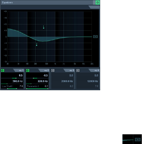
78
The mixer
The Equalizers + Curve pane in the Channel Settings win-
dow consists of four EQ modules with parameter sliders, an
EQ curve display and some additional functions at the top.
Using the parameter controls
1. Activate an EQ module by clicking its on/off button.
Although the modules have different default frequency values and differ-
ent Q names, they all have the same frequency range (20Hz to 20kHz).
The only difference between the modules is that you can specify different
filter types for each individual module (see below).
2. Set the amount of cut or boost with the gain control –
the upper slider.
The range is ± 24dB.
3. Set the desired frequency with the frequency slider.
This is the center frequency of the frequency range (20Hz to 20kHz) to
be cut or boosted.
4. Click on the lower slider (to the left) to open the filter
type pop-up menu and select the desired filter type.
The “eq1” and “eq4” bands can act as parametric, shelving or high/low-
pass filters, while “eq2” and “eq3” will always be parametric filters.
5. Set the Q value with the lower slider (to the right).
This determines the width of the affected frequency range. Higher values
give narrower frequency ranges.
6. If needed, you can activate and make settings for up to
four modules.
•Note that you can edit the values numerically as well, by
clicking in a value field and entering the desired gain, fre-
quency or Q value.
Using the curve display
When you activate EQ modules and make settings, you will
see that your settings are automatically reflected in the
curve display above. You can also make settings directly in
the curve (or combine the two methods any way you like):
1. To activate an EQ module, click in the curve display.
This adds a curve point and one of the modules below are activated.
2. Make EQ settings by dragging the curve point in the
display.
This allows you to adjust gain (drag up or down) and frequency (drag left
or right).
3. To set the Q parameter, press [Shift] and drag the
curve point up or down.
You will see the EQ curve become wider or narrower as you drag.
•You can also restrict the editing by pressing [Ctrl]/
[Command] (sets gain only) or [Alt]/[Option] (sets fre-
quency only) while you drag the curve point.
4. To activate another EQ module, click somewhere else
in the display and proceed as above.
5. To turn off an EQ module, double-click its curve point
or drag it outside the display.
6. To mirror (“inverse”) the eq curve on the x axis, click
the button to the right of the curve display.
The Inverse Equalizers button
EQ bypass
Whenever one or several EQ modules are activated for a
channel, the EQ button will light up in green in the mixer
channel strip, Inspector (Equalizer and Channel sections),
Track list and Channel Settings window (top right corner
of the EQ section).
You can also bypass all EQ modules. This is useful, as it
allows you to compare the sound with and without EQ.
Proceed as follows:
•In the mixer, the Track list and in the Channel section in
the Inspector, click the EQs state button so that it turns
yellow.
To deactivate EQ Bypass, click the button again, so that it turns green
again.
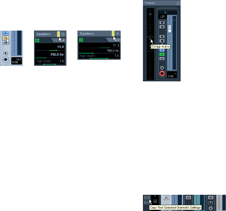
79
The mixer
•In the Inspector (Equalizers tab) and in the Channel
Settings window, click the Bypass button (next to the EQ
button) so that it turns yellow.
Click again to deactivate EQ Bypass mode.
EQ bypass in the mixer, the Channel Settings window and the Inspector
EQ reset
On the Presets pop-up menu in the Channel Settings win-
dow and in the Inspector, you will find the Reset command.
Select this to turn off all EQ modules and reset all EQ pa-
rameters to their default values.
Using EQ presets
Some useful basic presets are included with the program.
You can use them as they are, or as a starting point for fur-
ther “tweaking”.
•To call up a preset, pull down the presets pop-up menu
in the Channel Settings window or in the Inspector and
select one of the available presets.
•To store the current EQ settings as a preset, select
“Store Preset” on the presets pop-up menu and enter the
desired name for the preset in the dialog that appears.
•To rename the selected preset, select “Rename Preset”
on the pop-up menu and enter a new name.
•To delete the selected preset, select “Remove Preset”
on the pop-up menu.
ÖYou can also apply EQ (and Inserts) settings from
Track presets, see “Applying Inserts and EQ settings from
track presets” on page 158.
EQ in the channel overview
If the “Channel” section is selected in the Inspector, you
will get an overview of which EQ modules, insert effects
and sends are activated for the channel.
By clicking the respective indicator (1 to 4), you can turn
the corresponding EQ module on or off.
The channel overview in the Inspector
Copying settings between audio channels
It is possible to copy all channel settings for an audio chan-
nel and paste them to one or several other channels. This
applies to all audio-based channel types. For example, you
can copy EQ settings from an audio track and apply these
to a group or VST Instrument channel, if you want them to
have the same sound.
Proceed as follows:
1. In the mixer, select the channel you want to copy set-
tings from.
2. Click the “Copy First Selected Channel’s Settings”
button on the common panel.
3. Select the channel(s) you want to copy the settings to
and click the “Paste Settings to Selected Channels” button
(below the “Copy First Selected Channel Settings” button).
The settings are applied to the selected channel(s).
You can copy channel settings between different types of
channels, but only those channels will be used for which
corresponding settings are available in the target channel:
• For example, since output channels do not have send effects,
copying from them will leave the Sends settings in the target
channel unaffected.

80
The mixer
Initialize Channel and Reset Mixer
The Initialize Channel button can be found in the lower
part of the Control Strip section in the Channel Settings
window (if this section is not shown in the Channel Set-
tings window, open the context menu and select “Control
Strip” on the Customize View submenu). Initialize Channel
resets the selected channel to the default settings.
Similarly, the mixer common panel holds a Reset Mixer/
Reset Channels button – when you click this, you will be
asked whether you want to reset all channels or just the
selected channels.
The default settings are:
• All EQ, Insert and Send effect settings are deactivated and re-
set.
• Solo/Mute is deactivated.
• The fader is set to 0dB.
• Pan is set to center position.
Using group channels
You can route the outputs from multiple audio channels to
a group. This enables you to control the channel levels us-
ing one fader, apply the same effects and equalization to all
of them etc. To create a group channel, proceed as follows:
1. Select Add Track from the Project menu and select
“Group Channel” from the submenu that appears.
2. Select the desired channel configuration and click OK.
A group channel track is added to the Track list and a corresponding
group channel strip is added to the mixer. By default the first group chan-
nel strip is labeled “Group 1”, but you can rename it just like any channel
in the mixer.
3. Pull down the Output Routing pop-up for a channel
you want to route to the group channel, and select the
group channel.
The output of the audio channel is now redirected to the selected group.
4. Do the same for the other channels you wish to route
to the group.
Settings for group channels
The group channel strips are (almost) identical to audio
channel strips in the mixer. The descriptions of the mixer
features earlier in this chapter apply to group channels as
well. Some things to note:
•You can route the output of a group to an output bus or
to another group.
You cannot route a group to itself. Routing is done with the Output Rout-
ing pop-up menu in the Inspector (select the subtrack for the Group in
the Track list).
•There are no Input Routing pop-ups, Monitor buttons or
Record Enable buttons for group channels.
This is because inputs are never connected directly to a group.
•Solo functionality is automatically linked for channels
routed to a group and the group channel itself.
This means that if you solo a group channel, all channels routed to the
group are automatically soloed as well. Similarly, soloing a channel
routed to a group will automatically solo the group channel.
•Mute functionality depends on the setting “Group Chan-
nels: Mute Sources as well” in the Preferences (VST page).
By default, when you mute a group channel no audio will pass through
the group. However, other channels that are routed directly to that group
channel will remain unmuted. If any of those channels have aux sends
routed to other group channels, FX channels or output busses, those will
still be heard.
If the option “Group Channels: Mute Sources as well” is activated in the
Preferences (VST page), muting a group channel will cause all other
channels directly routed to it to be muted as well. Pressing mute again
will unmute the group channel and all other channels directly routed to it.
Channels that were muted prior to the group channel being muted will
not remember their mute status and will be unmuted when the group
channel is unmuted.
One application of group channels is to use them as “effect
racks” – see the chapter “Audio effects” on page 85.
!
The option “Group Channels: Mute Sources as well”
does not affect how mute automation is written. Writ-
ing mute automation on a group channel only affects
the group channel and not channels routed to it.
When writing the automation, you will see the other
channels being muted when this option is activated.
However, upon playback, only the group channel will
respond to the automation.
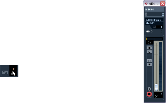
81
The mixer
About output busses
Cubase AI uses a system of input and output busses
which are set up using the VST Connections dialog. This
is described in the chapter “VST Connections: Setting up
input and output busses” on page 9.
Output busses let you route audio from the program to the
outputs on your audio hardware.
Viewing the output busses in the mixer
Output busses are shown as output channels in a sepa-
rate pane to the right in the mixer. You show or hide this
pane by clicking the Hide Output Channels button in the
mixer’s common panel.
Each output channel resembles a regular audio channel
strip. Here you can do the following:
• Adjust master levels for all configured output busses using the
level faders.
• Add effects or EQ to the output channels (see the chapter
“Audio effects” on page 85).
MIDI-specific procedures
This section describes basic procedures for MIDI chan-
nels in the mixer.
Using Channel Settings
For each MIDI channel strip in the mixer (and MIDI track in
the Track list or the Inspector), there is an Edit (“e”) button.
Clicking this opens the MIDI Channel Settings window.
By default, this window contains a duplicate of the mixer
channel strip.
You can customize the Channel Settings window, by
showing/hiding the different panels and/or by changing
their order:
• To specify, which panels should be shown/hidden, right-click
in the Channel settings window, and activate/deactivate the
respective options on the Customize View submenu on the
context menu.
• To change the order of the panels, select “Setup” on the Cus-
tomize View pop-up menu and use the “Move up” and “Move
Down” buttons in the dialog that opens.
Every MIDI channel has its own channel settings window.
The MIDI Channel Settings window
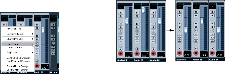
82
The mixer
Utilities
Link/Unlink channels
This function is used to “link” selected channels in the
mixer so that any change applied to one channel will be
mirrored by all channels in that group. You can link as
many channels as you like, and you can also create as
many groups of linked channels as you like. To link chan-
nels in the mixer, proceed as follows:
1. Press [Ctrl]/[Command] and click on all the channels
you want to link.
[Shift]-clicking allows you to select a continuous range of channels.
2. Right-click somewhere on the gray mixer panel.
The Mixer context menu appears.
3. Select “Link Channels” from the context menu.
•To unlink channels, select one of the linked channels and
select “Unlink Channels” from the Mixer context menu.
The channels are unlinked. Note that you do not have to select all the
channels that are linked, only one of them.
ÖIt is not possible to remove individual channels from
Link status.
To make individual settings to a linked channel, press [Alt]/[Option] when
changing the setting.
What will be linked?
The following rules apply for linked channels:
•Only level, mute, solo, select, monitor and record enable
will be linked between channels.
Effect/EQ/pan/input and output routing settings are not linked.
•Any individual channel settings you have made before
linking will remain until you alter the same setting for any of
the linked channels.
For example, if you link three channels, and one of them was muted at the
time you applied the Link Channel function, this channel will remain muted
after linking. However, if you mute another channel all linked channels will
be muted. Thus, the individual setting for one channel is lost as soon as
you change the same parameter setting for any of the linked channels.
•Fader levels will be “ganged”.
The relative level offset between channels will be kept if you move a
linked channel fader.
The three channels shown are linked. Pulling down one fader changes
the levels for all three channels, but keeps the relative level mix.
•By pressing [Alt]/[Option], you can make individual set-
tings and changes for channels that are linked.
ÖLinked channels have individual automation tracks.
These are completely independent, and are not affected
by the Link function.
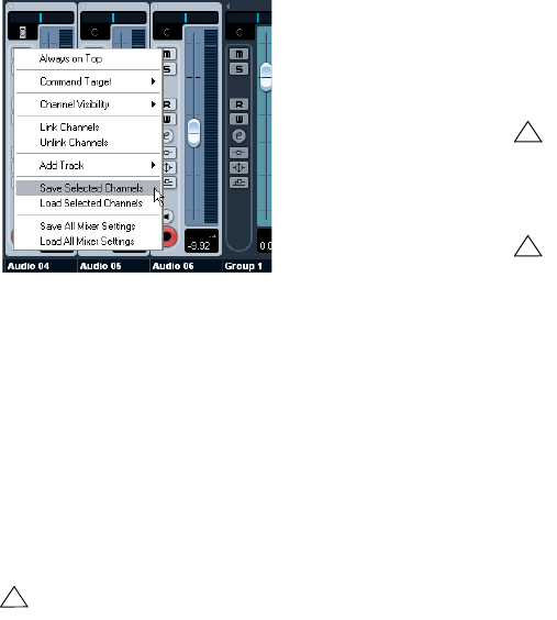
83
The mixer
Saving mixer settings
It is possible to save complete mixer settings for all or all
selected audio-related channels in the mixer. These can
later be loaded into any project. Channel settings are saved
as mixer settings files. These have the file extension “.vmx”.
Right-clicking somewhere in the mixer panel or in the
Channel Settings window brings up the context menu
where the following Save options can be found:
•“Save Selected Channels” will save all channel settings
for the selected channels.
•“Save All Mixer Settings” saves all channel settings for
all channels.
When you select any of the above options, a standard file
dialog opens where you can select a name and storage lo-
cation on your disk for the file.
Loading mixer settings
Loading Selected Channels
To load mixer settings saved for selected channels, pro-
ceed as follows:
1. Select the same number of channels in the new project
to match the number of channels you saved settings for in
the previous project.
For example, if you saved settings for six channels, select six channels in
the mixer.
•Mixer settings will be applied in the same order as they
were in the mixer.
Thus, if you save settings from channels 4, 6 and 8 and apply these set-
tings to channels 1, 2 and 3, the settings saved for channel 4 would be ap-
plied to channel 1, the settings saved for channel 6 to channel 2 and so on.
2. Right-click the mixer panel to open the context menu,
and select “Load Selected Channels”.
A standard file dialog appears, where you can locate the saved file.
3. Select the file and click “Open”.
The channel settings are applied to the selected channels.
Loading All Mixer Settings
Selecting “Load All Mixer Settings” from the context menu
allows you to open a saved mixer settings file, and have
the stored settings applied to all channels for which there
is information included in the file. All channels, output set-
tings, VST Instruments, sends and “master” effects will be
affected.
ÖPlease note that if the saved mixer settings were for
24 channels, for example, and the mixer you apply it to
currently contains 16 channels, only the settings for chan-
nels 1 to 16 will be applied – this function will not auto-
matically add channels.
!
Saving mixer settings does not apply to MIDI chan-
nels in the mixer – only audio-related channels
(group, audio, instrument, effect return, and VSTi)
are saved with this function!
!
Loading mixer settings does not apply to MIDI chan-
nels in the mixer – only audio-related channels (group,
audio, instrument, effect return, VSTi) are saved and
can be loaded with this function!
!
If you choose to apply mixer settings to fewer chan-
nels than you saved, the order of the saved channels
in the mixer applies – i.e. the saved channels that are
“left over” and not applied will be the channels with
the highest channel numbers (or furthest to the right
in the mixer).
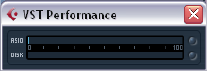
84
The mixer
About the VST Performance window
The VST Performance window is opened from the Devices
menu. The window shows two meter displays: The ASIO
meter, which indicates CPU load, and the Disk meter,
which shows the hard disk transfer rate. It is recommended
that you check this from time to time, or keep it always
open. Even if you have been able to activate a number of
audio channels in the project without getting any warning,
you may run into performance problems when adding EQ
or effects.
•The ASIO meter (at the top) shows the ASIO time usage,
i.e. the time required to complete the current processing
tasks. The more tracks, effects, EQ etc. you use in your
project, the longer processing will take, and the longer the
ASIO meter will show activity.
If the red Overload indicator lights up, you need to decrease the number
of EQ modules, active effects and/or audio channels playing back simul-
taneously.
•The lower bar graph shows the hard disk transfer load.
If the red overload indicator lights up, the hard disk is not supplying data
fast enough to the computer. You may need to reduce the number of tracks
playing back by using the Disable Track function (see “About track disable/
enable” on page 45). If this does not help, you need a faster hard disk.
Note that the overload indicator may occasionally blink, e.g. when you lo-
cate during playback. This does not indicate a problem, but happens be-
cause the program needs a moment for all channels to load data for the
new playback position.
ÖThe ASIO and Disk load meters can also be shown on
the Transport panel (as “Performance”) and on the Project
window toolbar (as “Performance Meter”).
There they are shown as two miniature vertical meters (by default at the
left side of the panel/toolbar).
8
Audio effects
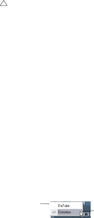
86
Audio effects
About this chapter
Cubase AI comes with a number of effect plug-ins in-
cluded. This chapter contains general details about how to
assign, use and organize effect plug-ins. The effects and
their parameters are described in the separate manual
“Plug-in Reference”.
Overview
There are two ways to use audio effects in Cubase AI:
•As insert effects.
An insert effect is inserted into the signal chain of an audio channel, which
means that the whole channel signal passes through the effect. This makes
inserts suitable for effects for which you do not need to mix dry and wet
sound, e.g. distortion, filters or other effects that change the tonal or dy-
namic characteristics of the sound. You can have up to eight different in-
sert effects per channel (and the same is true for output busses – for
recording with “master effects”).
•As send effects.
Each audio channel has eight sends, each of which can be freely routed
to an effect (or to a chain of effects). Send effects are practical for two
reasons: you can control the balance between the dry (direct) and wet
(processed) sound individually for each channel using the sends, and
several different audio channels can use the same send effect. In Cu-
base AI, send effects are handled by means of FX channel tracks.
About VST 3
The new VST 3 plug-in standard offers many improve-
ments over the previous VST 2 standard, yet retains full
backwards compatibility, i.e. you will still be able to use
your previous VST effects and presets.
In the program, effects compatible with previous VST ver-
sions will be easily recognized:
VST Preset management
From a user perspective, the main difference between
VST 2 and VST 3 is in the effect preset management. The
“.fxp/.fxb” files used in VST 2 have been replaced by
VST 3 Presets (extension “.vstpreset”). Using the preset
management features, you can assign various attributes to
your effect presets to help you quickly find the right patch.
You can also preview effect presets before you load them.
A large number of presets for effects are included with the
program. If you have any previous VST plug-ins installed
on your computer, you can still use them, and you can also
convert their programs to VST 3 presets, see “Effect pre-
sets” on page 94.
Smart plug-in processing
Another feature of the VST3 standard is “smart” plug-in
processing. Previously, any loaded plug-in was processing
continuously, regardless of whether a signal was present or
not. In VST3, processing by a plug-in can be disengaged if
there is no signal present. This can greatly reduce the CPU
load, thus allowing for more effects to be used.
This is achieved by activating the option “Suspend VST3
plug-in processing when no audio signals are received” in
the Preferences dialog (VST–Plug-ins page).
When this is activated, VST 3 plug-ins will not consume
CPU power on silent passages, i.e. when no audio data
runs through them.
Be aware, however, that this can lead to a situation where
you added more plug-ins on “transport stop” than the sys-
tem can handle on playback. Therefore, you should always
find the passage with the largest number of events playing
simultaneously to make sure that your system offers the re-
quired performance.
ÖActivating this option can increase your system perfor-
mance a lot in certain projects, but it also makes it more
unpredictable whether the project can play back fine on
any timecode position of the project.
!
This chapter describes audio effects, i.e. effects that
are used to process audio, group, and VST Instrument
channels.
An effect compatible
with a previous VST
version A VST 3 effect
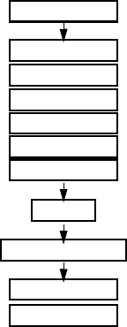
87
Audio effects
About plug-in delay compensation
A plug-in effect may have some inherent delay or latency.
This means that it takes a brief time for the plug-in to pro-
cess the audio fed into it – as a result, the output audio
will be slightly delayed. This especially applies to dynam-
ics processors featuring “look-ahead” functionality.
Cubase AI provides full plug-in delay compensation
throughout the entire audio path. All plug-in delays are
compensated for, maintaining the sync and timing of all
audio channels.
Normally, you do not have to make any settings for this.
However, VST3 dynamics plug-ins with look-ahead func-
tionality have a “Live” button, allowing you to disengage
the look-ahead to minimize latency, if they are to be used
during realtime recording (see the separate manual “Plug-
in Reference”).
You can also constrain the delay compensation, which is
useful to avoid latency when recording audio or playing a
VST Instrument in real time, see “Constrain Delay Com-
pensation” on page 106.
About tempo sync
Plug-ins can receive timing and tempo information from the
host application (in this case, Cubase AI). Typically, this is
used to synchronize certain plug-in parameters (such as
modulation rates or delay times) to the project tempo.
•This information is automatically provided to any VST
plug-in (2.0 or later) that “requests it”.
You do not have to make any special settings for this.
•You set up tempo sync by specifying a base note value.
You can use straight, triplet or dotted note values (1/1 to 1/32).
Please refer to the separate manual “Plug-in Reference”
for details about the included effects.
Insert effects
Background
As the name implies, insert effects are inserted into the
audio signal path – this means that the audio channel data
will be routed through the effect. You can add up to eight
different insert effects independently for each audio-re-
lated channel (audio track, group channel track, FX chan-
nel track or VST Instrument channel) or output bus. The
signal passes through the effects in series from the top
downwards, with the signal path shown below:
As you can see, the last two insert slots (for any channel)
are post-EQ and post-fader. Post-fader slots are best
suited for insert effects where you do not want the level to
be changed after the effect, such as dithering (see “Dithe-
ring” on page 89) and maximizers – both typically used as
insert effects for output busses.
ÖApplying several effects on several channels may be
too much for your CPU to handle!
If you want to use the same effect with the same settings on several
channels, it may be more efficient to set up a group channel and to apply
your effect only once, as a single insert for this group. You can use the
VST Performance window to keep an eye on the CPU load.
Input gain
Insert effect 1
Insert effect 2
Insert effect 3
Insert effect 6
EQ
Volume (fader)
Insert effect 7
Insert effect 8
Insert effect 4
Insert effect 5
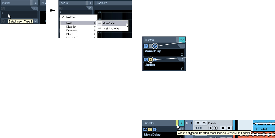
88
Audio effects
Routing an audio channel or bus through
insert effects
Insert effect settings are available in the Channel Settings
window and the Inspector. The examples below show the
Channel Settings window, but the procedures are the
same for all the inserts sections:
1. Bring up the Channel Settings window.
By default, the inserts are located to the far left.
2. Pull down the effect type pop-up for one of the insert
slots, and select an effect.
The effect is loaded and automatically activated and its con-
trol panel opens. You can open or close the control panel
for an effect by clicking the “e” button for the insert slot.
•If the effect has a dry/wet Mix parameter, you can use
this to adjust the balance between the dry signal and the
effect signal.
See “Editing effects” on page 94 for details about editing effects.
•To remove an effect, pull down the effect type pop-up
menu and select “No Effect”.
You should do this for all effects that you do not intend to use, to reduce
the CPU load.
•You can add up to 8 insert effects per channel this way.
•You can reorder the effects by clicking in the area above
the name field and dragging the effect onto another slot.
•You can copy an effect into another effect slot (for the
same channel or between channels) by holding down [Ctrl]/
[Command] and dragging it onto another effect slot.
Deactivating vs. bypassing
If you want to listen to the track without having it pro-
cessed by a particular effect, but do not want to remove
this effect completely from the insert slot, you can either
deactivate or bypass it.
Deactivating means to terminate all processing, whereas
bypassing means to play back only the unprocessed origi-
nal signal – a bypassed effect is still processing in the
background. Bypassing allows for crackle-free comparison
of the original (“dry”) and the processed (“wet”) signal.
•To deactivate an effect, click the blue button on the left
above the insert slot.
•To bypass an effect, click its Bypass button (the middle
button above the insert slot).
When an effect is bypassed, this button is yellow.
•To bypass all inserts for a track, click the global bypass
button.
This button can be found at the top of the Inserts section in the Inspector
or the Channel Settings window. It lights up in yellow to indicate that the
inserts of this track are bypassed. In the Track list and the channel strip in
the mixer, the Inserts State button will also light up in yellow.
This effect is activated, and its control
panel is open.
This insert effect is bypassed.
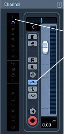
89
Audio effects
Insert effects in the channel overview
If the “Channel” section is selected in the Inspector, you will
get an overview of which insert effects, EQ modules and ef-
fect sends are activated for the channel.
You can activate or deactivate individual insert effect slots
by clicking the corresponding number (in the top part of
the overview).
The channel overview in the Inspector
Adding insert effects to output busses
All output busses have eight insert slots, just like regular
audio channels. The procedures for adding insert effects
are the same.
•Insert effects added to an output bus will affect all audio
routed to that bus, like a “master insert effect”.
Typically you would add compressors, limiters, EQ or other plug-ins to
tailor the dynamics and sound of the final mix. Dithering is a special case,
as described below.
ÖPlease note that the output busses only appear as
tracks in the Track list, when their automation W(rite) but-
tons have been activated once. Therefore you can only
use the Inspector section to make Inserts settings for the
busses if you have activated Write automation for the re-
spective bus beforehand.
However, you can always make Inserts settings in the Channel Settings
window.
Dithering
Dithering is a method for controlling the noise produced
by quantization errors in digital recordings. The theory be-
hind this is that during low level passages, only a few bits
are used to represent the signal, which leads to quantiza-
tion errors and hence distortion.
For example, when “truncating bits”, as a result of moving
from 24 to 16 bit resolution, quantization errors are added
to an otherwise immaculate recording. By adding a spe-
cial kind of noise at an extremely low level, the effect of
these errors is minimized. The added noise could be per-
ceived as a very low-level hiss under exacting listening
conditions. However, this is hardly noticeable and much
preferred to the distortion that otherwise occurs.
ÖNote that there is no Dithering plug-in included with
Cubase AI. To use this function, you have to have a dither-
ing plug-in installed on your computer.
When should I use dithering?
•Consider dithering when you mix down to a lower reso-
lution, either in realtime (during playback) or with the Ex-
port Audio Mixdown function.
A typical example is when you mix down a project to a 16-bit stereo au-
dio file for audio CD burning.
What is a “lower resolution” then? Well, Cubase AI uses
32-bit float resolution internally, which means that all inte-
ger resolutions (16 bit, 24 bit, etc.) are lower. The negative
effects of truncation (no dithering) are most noticeable
when mixing down to 8 bit, 16 bit and 20 bit format;
whether to dither when mixing down to 24 bits is a matter
of taste.
Applying dithering
1. Open the VST Output Channel Settings window by
clicking the “e” button for the Output channel in the mixer.
2. Open the Inserts pop-up menu for slot 7 or 8.
The two last Insert effect slots (for all channels) are post-fader, which is
crucial for a dithering plug-in. The reason is that any master gain change
applied after dithering would bring the signal back to the internal 32 bit
float domain, rendering the dithering settings useless.
3. Select a dithering plug-in from the pop-up menu.
The blue color of inserts 1 and 2 and the
blue Inserts State button in the channel strip
indicate that this track has active inserts.
90
Audio effects
4. Make sure the plug-in is set to dither to the correct
resolution.
This would be the resolution of your audio hardware (on playback) or the
desired resolution for the mixdown file you want to create (as set in the
Export Audio Mixdown dialog, see the chapter “Export Audio Mixdown”
on page 226).
5. Use the other parameters in the control panel to set up
the dithering to your liking.
Using group channels for insert effects
Like all other channels, group channels can have up to
eight insert effects. This is useful if you have several audio
tracks that you want to process through the same effect
(e.g. different vocal tracks that all should be processed by
the same compressor).
Another special use for group channels and effects is the
following:
If you have a mono audio track and want to process this
through a stereo insert effect (e.g. a stereo chorus or an
auto panner device), you cannot just insert the effect as
usual. This is because the audio track is in mono – the
output of the insert effect will be in mono as well, and the
stereo information from the effect will be lost.
One solution would be to route a send from the mono track
to a stereo FX channel track, set the send to pre-fader
mode and lower the fader completely for the mono audio
track. However, this makes mixing the track cumbersome,
since you cannot use the fader.
Here’s another solution:
1. Create a group channel track in stereo and route it to
the desired output bus.
2. Add the desired effect to the group channel as an in-
sert effect.
3. Route the mono audio track to the group channel.
Now the signal from the mono audio track is sent directly
to the group, where it passes through the insert effect, in
stereo.
Send effects
Background
As their name implies, send effects are outside of an audio
channel’s signal path, i.e. the audio data to be processed
must be sent to the effect (as opposed to insert effects,
which are inserted into the channel’s signal path).
To this end, Cubase AI provides FX channel tracks. When
you have created such a track, it is added to the Track list
and can be selected as a routing target in the Send slots
of audio channels.
•When selecting an FX channel track in one of the send
slots of an audio channel, the audio is sent to the FX chan-
nel and through any insert effects set up for it.
Each audio channel has eight sends, which can be routed to different FX
channels, and thus different FX channel insert effect configurations. You
control the amount of signal sent to the FX channel by adjusting the effect
send level.
•If you have added several effects to the FX channel, the
signal passes through the effects in series, from the top
(the first slot) downward.
This allows for “custom” send effect configurations – e.g. a chorus fol-
lowed by a reverb followed by an EQ and so on.
•The FX channel track has its own channel strip in the
mixer, the effect return channel.
Here you can adjust the effect return level and balance, add EQ and
route the effect return to any output bus.
•Each FX channel track can have an automation track, for
automating various effect parameters.
See the chapter “Automation” on page 108 for more information.
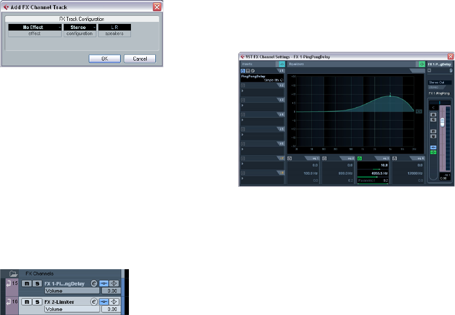
91
Audio effects
Setting up send effects
Adding an FX channel track
1. Pull down the Project menu and select “FX Channel”
from the “Add Track” submenu.
A dialog appears.
2. Select a channel configuration for the FX channel track.
Normally, stereo is a good choice since most effect plug-ins have stereo
outputs.
3. Select an effect for the FX channel track.
This is not strictly necessary at this point – you can also leave the plug-in
pop-up menu set to “No Effect” and add effects to the FX channel later.
4. Click OK.
An FX channel track is added to the Track list, and the selected effect, if
any, is loaded into the first insert effect slot for the FX channel (in that
case, the lit Inserts tab for the FX channel track in the Inspector indicates
that an effect has been assigned and automatically activated).
•All FX channel tracks you create will appear in a dedi-
cated “folder” track in the Track list.
This makes it easy to manage and keep track of all your FX channel
tracks, and also allows you to save screen space by folding in the FX
Channel folder.
FX channel tracks are automatically named “FX 1”, “FX 2” etc., but you
can rename them if you wish. Just double-click the name of an FX chan-
nel track in either the Track list or the Inspector and type in a new name.
Adding and setting up effects
As mentioned above, you can add a single insert effect
when you create the FX channel track. To add and set up
effects after the FX channel track is created, you can ei-
ther use the Inspector for the track (click the Inserts tab)
or the VST FX Channel Settings window:
1. Click the Edit (“e”) button for the FX channel track (in
the Track list, mixer or Inspector).
The VST FX Channel Settings window appears, similar to a regular
Channel Settings window.
On the left in the window you can find the Inserts section with eight ef-
fect slots.
2. Make sure the FX channel is routed to the correct out-
put bus.
This is done with the Output Routing pop-up menu at the top of the fader
section (also available in the Inspector).
3. To add an insert effect in an empty slot (or to replace
the current effect in a slot), click in the slot and select an
effect from the pop-up menu.
This works just like when selecting insert effects for a regular audio
channel.
4. When you add an effect, its control panel will automat-
ically appear. When you set up send effects, you would
normally set the wet/dry Mix control to all “wet”.
This is because you control the balance between the wet and the dry sig-
nal with the effect sends. For more information, see “Editing effects” on
page 94.
•You can add up to eight effects for an FX channel.
The signal will pass through all the effects in series. It is not possible to
adjust the send and return levels separately for the effects – this is done
for the FX channel as a whole. If what you want is several separate send
effects (where you can control the send and return levels independently),
you should instead add more FX channel tracks – one for each effect.
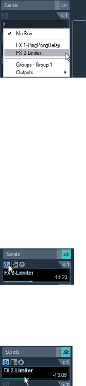
92
Audio effects
•You can reorder the effects by clicking in the area above
the name field and dragging the effect onto another slot.
•You can copy an effect into another effect slot (for the
same channel or between channels) by holding down [Ctrl]/
[Command] and dragging it onto another effect slot.
•To remove an insert effect from a slot, click in the slot
and select “No Effect” from the pop-up menu.
You should do this for all effects that you do not intend to use, to reduce
the CPU load.
•You can bypass individual effects (or all effects) by
clicking the corresponding Bypass button(s) for the FX
channel track.
See “Routing an audio channel or bus through insert effects” on page 88.
•You can also adjust level, pan and EQ for the effect re-
turn in the FX Channel Settings window.
This can also be done in the mixer or in the Inspector.
ÖRemember that the more effect units you use, the
higher the CPU load.
Making settings for the sends
The next step is to set up a send for an audio channel and
route it to the FX channel. This can be done in the Chan-
nel Settings window or in the Inspector for the audio track.
The example below shows the Channel Settings window,
but the procedure is similar for all the sections:
1. Click the “e” button for an audio channel to bring up its
Channel Settings window.
By default, the send section is located to the left of the
channel strip. Each of the eight sends has the following
controls:
• An On/Off button for activating/deactivating the effect
• A send level slider
• A pre/post-fader switch
• An “e” (edit) button
Note that the last three items are not shown until the send
is activated and an effect has been loaded.
2. Pull down the Routing pop-up menu for a send by
clicking in the empty slot, and select the desired routing
destination.
• If the first item on this menu (“No Bus”) is selected, the send is
not routed anywhere.
• Items called “FX 1”, “FX 2” etc. correspond to existing FX
tracks. If you renamed an FX track (see “Adding an FX channel
track” on page 91), that name will appear on this menu instead
of the default.
• The menu also allows for routing a send directly to output bus-
ses, separate output bus channels or Group channels.
3. Select an FX channel track from the pop-up menu.
Now the send is routed to the FX channel.
4. Click the power button for the effect send so that it
lights up in blue.
This activates the send.
5. Click and drag the send level slider to a moderate
value.
The send level determines how much of the signal from the audio chan-
nel is routed to the FX channel via the send.
Setting the Send level.
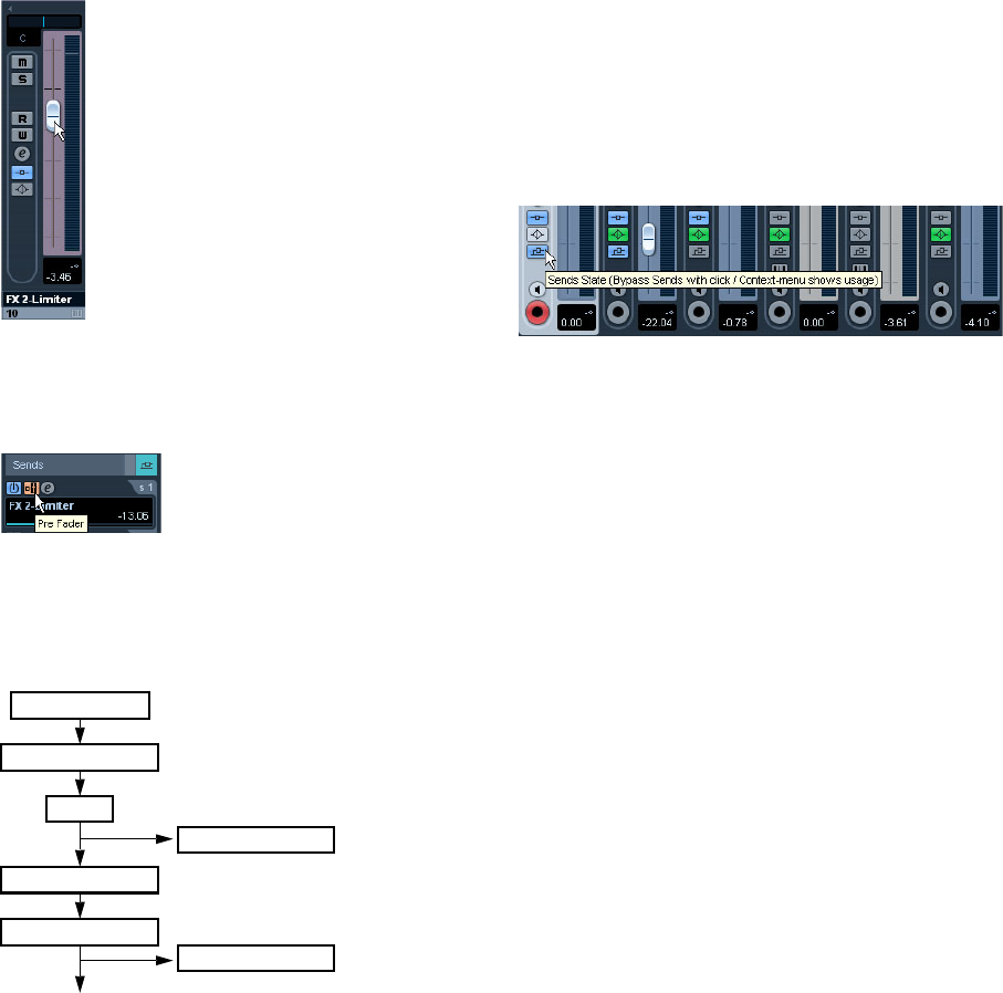
93
Audio effects
•In the mixer, you can use the level fader for the FX chan-
nel to set the effect return level.
By adjusting the return level, you control the amount of the signal sent
from the FX channel to the output bus.
Setting the effect return level.
6. If you want the signal to be sent to the FX channel be-
fore the audio channel’s volume fader in the mixer, click on
the Pre-Fader button for the send so that it lights up.
A send set to pre-fader mode.
Normally you want the effect send to be proportional to
the channel volume (post-fader send). The picture below
shows where the sends are “tapped” from the signal in
pre and post-fader mode:
ÖYou can choose whether a send in pre-fader mode
should be affected by the channel’s Mute button or not.
This is done with the option “Mute Pre-Send when Mute” in the Prefe-
rences dialog (VST page).
•When one or several sends are activated for a channel,
the Send Effects buttons light up in blue.
Bypassing the sends
•In the mixer, you can click on the lit (blue) Sends State
button for a channel to bypass (disable) all its sends.
When the sends are bypassed, the button is yellow. Click the button again
to enable the sends.
•In the Inspector and the Channel Settings window, click
the button to the left of the Sends button (so that it lights
up yellow) to bypass the sends.
•You can also bypass individual sends in the channel
overview.
See “Insert effects in the channel overview” on page 89.
•You can also bypass the send effects by clicking the
“Bypass Inserts” button for the FX channel.
This bypasses the actual effects which may be used by several different
channels. Bypassing a send affects that send and that channel only. If
you bypass the insert effects, the original sound will be passed through.
This may lead to unwanted side effects (higher volume). To deactivate all
effects, use the mute button in the FX channel.
FX channels and the Solo Defeat function
When mixing, you might sometimes want to solo specific
audio channels, and listen only to these while other chan-
nels are muted. However, this will mute all FX channels as
well. If the soloed audio channels have sends routed to FX
channels, this means you will not hear the send effects for
the channels.
To remedy this, you can use the Solo Defeat function for
the FX channel:
1. [Alt]/[Option]-click the Solo button for the FX channel.
This activates the Solo Defeat function for the FX channel. In this mode,
the FX channel will not be muted if you solo another channel in the mixer.
Insert effects 1–6
EQ
Volume (fader)
Pre-fader sends
Post-fader sends
Insert effects 7–8
Input gain
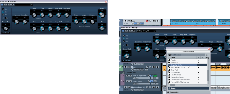
94
Audio effects
2. You can now solo any of the audio channels without
having the effect return (the FX channel) muted.
•To turn off the Solo Defeat function for the FX channel,
[Alt]/[Option]-click the Solo button for the FX channel
again.
Editing effects
All inserts and sends have an Edit (“e”) button. Clicking
this opens the control panel for the effect, in which you
can make parameter settings.
The contents, design and layout of the control panel de-
pends on the selected effect. However, all effect control
panels have an On/Off button, a Bypass button, Read/
Write automation buttons (for automating effect parame-
ter changes, see the chapter “Automation” on page 108),
a preset pop-up menu and a Preset Management pop-up
menu for saving and loading effect presets.
The Rotary effect control panel
•Please note that all effects can be edited using a simpli-
fied control panel (horizontal sliders only, no graphics). This
panel is opened by pressing [Ctrl]/[Command]-[Alt]/[Op-
tion]-[Shift] and clicking on the Edit button for the effect
send or slot.
Effect control panels may have any combination of knobs,
sliders, buttons and graphic curves.
ÖThe included effects and their parameters are de-
scribed in detail in the separate manual “Plug-in Refer-
ence”.
•If you edit the parameters for an effect, these settings
are saved automatically with the project.
•You can also save the current settings as a preset, see
below.
•Effects parameters can be automated – see the chapter
“Automation” on page 108.
Effect presets
Effect preset management in Cubase AI is very versatile.
In the Save Preset dialog you can assign attributes to pre-
sets which allow you to organize and browse them ac-
cording to various criteria. Cubase AI comes with
categorized track and VST presets that you can use
straight out of the box. You can also preview effect pre-
sets before loading them which considerably speeds up
the process of finding the right effect preset.
Selecting effect presets
Most VST effect plug-ins come with a number of useful
presets for instant selection.
To select an effect preset in the Presets browser, proceed
as follows:
1. Load an effect, either as a channel insert or into an FX
channel.
The control panel for the effect is displayed.
2. Click in the preset field at the top of the control panel.
This opens the Presets browser.
•You can also open the Presets browser from the In-
spector (Inserts tab) or the Channel Settings window.
3. Select the desired preset in the list.
4. Activate playback to audition the selected preset.
Simply step through the presets until you found the right sound. It may be
helpful to set up cycle playback of a section to make comparisons be-
tween different preset settings easier.
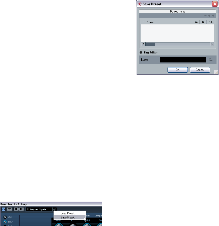
95
Audio effects
5. Double-click on the desired preset (or click outside
the Presets browser) to apply the preset.
•To return to the preset that was selected when you
opened the Presets browser, click the Reset button.
•You can also open the Presets browser by clicking the
button to the right of the preset field an selecting “Load
Preset” from the Preset Management pop-up menu.
•The preset handling for VST 2 plug-ins is slightly differ-
ent, see “About earlier VST effect presets” on page 96.
The Browser sections
The Presets browser contains the following sections:
•The “Search & Viewer” section (displayed by default)
lists the available presets for the selected effect.
•The Filter section (displayed when you click the Catego-
ries button) shows the available preset attributes for the
selected effect.
If no attributes have been specified for the effect presets, the columns
will be empty. If attributes have been assigned to a preset for this effect,
you can click on the attribute in the respective column (Category, Style
etc.), to filter out all presets that do not match the selected attribute(s).
•If you also activate the “Show Location” button, the
Browser & Filter section is displayed, allowing you to
specify the Presets folder that should be searched for
preset files.
Saving effect presets
You can save your edited effect settings as presets for
further use (e.g. in other projects):
1. Open the Preset Management pop-up menu.
2. Select “Save Preset…” from the pop-up menu.
This opens a dialog where you can save the current settings as a preset.
3. In the File name field in the lower part of the Save Pre-
set dialog, enter a name for the new preset.
•If you wish to assign attributes to the preset, click the
Tag Editor button.
Click in the Value column to select an appropriate “tag” for one or sev-
eral of the available categories in the Attributes column.
4. Click OK to store the preset and exit the dialog.
User-defined presets are saved in the following location:
• Windows XP: \Documents and Settings\<user name>\Appli-
cation data\VST3 presets\<company>\<plug-in name>
• Windows Vista: \Users\<user name>\AppData\Roaming\
VST3 presets\<company>\<plug-in name>
• Mac: /Users/<user name>/Library/Audio/Presets/<com-
pany>/<plug-in name>
You cannot change the default folder, but you can add fur-
ther subfolders inside the individual effect preset folders.
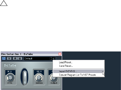
96
Audio effects
About earlier VST effect presets
As stated previously, you can use any VST 2.x plug-ins in
Cubase AI. For a description of how to add VST plug-ins,
see “Installing and managing effect plug-ins” on page 96.
When you add a VST 2 plug-in, any previously stored pre-
sets for it will be in the old FX program/bank format (.fxp/
.fxb). You can import such files, but the preset handling will
be slightly different. You will not be able to use the new fea-
tures until you have converted the old “.fxp/.fxb” presets to
VST 3 presets. If you save new presets for the included
VST 2 plug-ins, these will automatically be saved in the new
“.vstpreset” format.
Importing and converting FXB/FXP files
To import .fxp/.fxb files, proceed as follows:
1. Load any VST 2 effect you may have installed, and
open the Preset Management pop-up menu.
2. Select “Import FXB/FXP…” from the pop-up.
This menu item is only available for VST 2 plug-ins.
3. In the file dialog that opens, locate the .fxp file and
click Open.
If you load a bank (.fxb), it will replace the current set of all effect pro-
grams. If you load a single program, it will replace the currently selected
effect program only. Note that such files exist only if you created your
own .fxp/.fxb presets with a previous version of Cubase AI (or any other
VST 2 application).
4. After importing, you can convert the current program
list to VST presets by selecting “Convert Program List to
VST Presets” from the Preset Management pop-up.
After converting, the presets will be available in the Presets browser. The
new converted presets will be stored in the VST3 Preset folder.
Installing and managing effect
plug-ins
Cubase AI supports two plug-in formats; the VST 2 format
(with the file name extensions “.dll” on the PC and “.VST”
on the Mac) and the VST 3 format (extension “.vst3” on
both platforms). The formats are handled differently when
it comes to installation and organizing.
Installing additional VST plug-ins
Installing VST 3 plug-ins under Mac OS X
To install a VST 3.x plug-in under Mac OS X, quit Cubase
AI and drag the plug-in file into one of the following folders:
•/Library/Audio/Plug-Ins/VST3/
This is only possible if you are the system administrator. Plug-ins in-
stalled in this folder will be available to all users, for all programs that
support them.
•/Users/<user name>/Library/Audio/Plug-Ins/VST3/
“<user name>” is the name you use to log on to the computer (the easi-
est way to open this folder is to go to your “Home” folder and use the
path /Library/Audio/Plug-Ins/VST3/ from there). Plug-ins installed in this
folder are only available to you.
When you launch Cubase AI again, the new effects will ap-
pear on the effect pop-up menus. In the VST 3 protocol, the
effect category, sub-folder structure etc. are built-in and
cannot be changed. The effect(s) will simply show up in the
assigned category folder(s) on the Effect pop-up menu.
Installing VST 2.x plug-ins under Mac OS X
To install a VST 2.x plug-in under Mac OS X, quit Cubase
AI and drag the plug-in file to one of the following folders:
•/Library/Audio/Plug-Ins/VST/
This is only possible if you are the system administrator. Plug-ins in-
stalled in this folder will be available to all users, for all programs that
support them.
•<user name>/Library/Audio/Plug-Ins/VST/
“<user name>” is the name you use to log on to the computer (the easi-
est way to open this folder is to go to your “Home” folder and use the
path /Library/Audio/Plug-Ins/VST/ from there). Plug-ins installed in this
folder are only available to you.
When you launch Cubase AI again, the new effects will
appear on the effect pop-up menus.
!
All VST 2 presets can be converted to VST 3 presets.
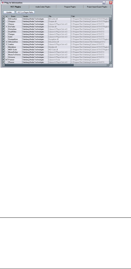
97
Audio effects
ÖIf an effect plug-in comes with its own installation ap-
plication, you should use this.
As a general rule, always read the documentation or readme files before
installing new plug-ins.
Installing VST 3 plug-ins under Windows
Under Windows, VST 3 plug-ins are installed by dragging
the files (with the extension “.vst3”) into the vst3 folder in
the Cubase AI application folder. When you launch Cubase
AI again, the new effects will appear on the Effect pop-up
menus. In the VST 3 protocol, the effect category, sub-
folder structure etc. are built-in and cannot be changed.
The installed new effect(s) will simply show up in the as-
signed category folder(s) on the effect pop-up menu.
Installing VST 2 plug-ins under Windows
Under Windows, VST 2.x plug-ins are installed by dragging
the files (with the extension “.dll”) into the Vstplugins folder
in the Cubase AI application folder, or into the Shared VST
Plug-in folder – see below. When you launch Cubase AI
again, the new effects will appear on the effect pop-up
menus.
ÖIf an effect plug-in comes with its own installation ap-
plication, you should use this.
As a general rule, always read the documentation before installing new
plug-ins.
Organizing VST 2 plug-ins
If you have a large number of VST 2 plug-ins, having them
all on a single pop-up menu in the program may become
unmanageable. For this reason, the VST 2 plug-ins in-
stalled with Cubase AI are placed in appropriate subfold-
ers according to the effect type.
•Under Windows, you can organize VST plug-ins by mov-
ing, adding or renaming subfolders within the Vstplugins
folder.
When you launch the program and pull down an effects pop-up menu,
the subfolders will be represented by hierarchical submenus, each listing
the plug-ins in the corresponding subfolder.
•Under Mac OS X, you cannot change the hierarchic ar-
rangement of the “built-in” VST plug-ins.
However, you can arrange any additional plug-ins you have installed (in the
/Library/Audio/Plug-Ins/VST/ folders, see above) by placing them in sub-
folders. In the program, the subfolders will be represented by hierarchical
submenus, each listing the plug-ins in the corresponding subfolder.
The Plug-in Information window
On the Devices menu, you will find an item called “Plug-in
Information”. Selecting this opens a dialog listing all the
available VST compatible plug-ins in your system (includ-
ing VST Instruments).
Managing and selecting VST plug-ins
To display all available VST plug-ins, open the “VST
PlugIns” tab.
•To enable a plug-in (make it available for selection), put
a check mark in the left column.
Only the enabled plug-ins will appear on the effect menus.
•The Instances column indicates how many instances of
the plug-in are currently used in Cubase AI.
Clicking in this column for a plug-in which is already in use produces a
pop-up showing exactly where each use occurs.
ÖA plug-in may be in use even if it is not enabled in the
left column.
You might for example have opened a project containing effects that are
currently disabled on the menu. The left column only determines whether
or not the plug-in will be visible on the effect menus.
•All columns can be resized by dragging the divider in
the column header.
The other columns show the following information about
each plug-in:
Column Description
Name The name of the plug-in.
Vendor The manufacturer of the plug-in.
File This shows the complete name of the plug-in (with extension).
Category This indicates the category of each plug-in (such as VST In-
struments, etc.).
Version Shows the version of the plug-in.

98
Audio effects
Update button
Clicking this button will make Cubase AI re-scan the des-
ignated VST folders for updated plug-in information.
VST 2.x Plug-in Paths button
This opens a dialog where you can see the current paths
to where VST 2.x plug-ins are located. You can add/re-
move folder locations by using the corresponding buttons.
If you click “Add”, a file dialog is opened, where you can
select a folder location.
About the “shared” plug-ins folder (Windows and VST
2.x only)
You can designate a “shared” VST 2.x plug-ins folder.
This will allow VST 2.x plug-ins to be used by other pro-
grams that support this standard.
You designate a shared folder by selecting a folder in the
list and clicking the “Set As Shared Folder” button in the
VST 2.x Plug-in Paths dialog.
Exporting plug-in information files
You can also save plug-in information as an .xml file, e.g.
for archiving purposes or troubleshooting. The Export func-
tion is available for VST, MIDI and Audio Codec plug-ins.
Proceed as follows:
1. Right-click on the desired tab in the Plug-in Information
window to open the context menu and select “Export”.
A file dialog opens.
2. In the dialog, specify a name and location for the Plug-
in Information export file and click OK to export the file.
•The Plug-in Information file contains information on the
installed/available plug-ins, their version, vendor, etc.
•The .xml file can then be opened in any editor applica-
tion supporting the xml format.
SDK Shows with which version of the VST protocol a plug-in is
compatible.
Latency This shows the delay (in samples) that will be introduced if the
effect is used as an Insert. This is automatically compensated
for by Cubase AI.
I/O This column shows the number of inputs and outputs for each
plug-in.
Path The path and name of the folder in which the plug-in file is
located.
Column Description
9
VST Instruments and Instrument tracks
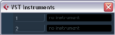
100
VST Instruments and Instrument tracks
Introduction
VST Instruments are software synthesizers (or other sound
sources) that are contained within Cubase AI. They are
played internally via MIDI. You can add effects or EQ to
VST Instruments, just as with audio tracks.
The VST Instrument HALionOne is included with Cubase
AI, others can be purchased separately from Steinberg
and other manufacturers.
ÖThis chapter describes the general procedures for
setting up and using VST Instruments.
For a description of HALionOne and its parameters, see the separate
PDF document “Plug-in Reference”.
ÖDepending on the VST version the instrument is com-
patible with, an icon may be displayed in front of the in-
strument name, see “About VST 3” on page 86.
VST Instrument channels vs.
instrument tracks
Cubase AI allows you to make use of VST Instruments in
two different ways:
•By activating instruments in the VST Instruments window.
This creates a VST Instrument channel, which can be played by one (or
several) MIDI track(s) routed to it.
•By creating instrument tracks.
Instrument tracks are a combination of a VST Instrument, an instrument
channel and a MIDI track. You play and record MIDI note data directly for
this track.
Both methods have their advantages, and should be se-
lected according to what best suits your needs. The fol-
lowing sections describe the two approaches.
VST Instrument channels
You can access a VST Instrument from within Cubase AI
by creating a VST Instrument channel and associating this
channel with a MIDI track. Proceed as follows:
1. On the Devices menu, select “VST Instruments”.
The VST Instruments window opens.
2. Click in one of the empty slots to open the instrument
pop-up menu and select the desired instrument.
3. You will be asked if you want to create an associated
MIDI track connected to the VST Instrument. Do so.
The instrument is loaded and activated, and its control panel is opened.
A MIDI track with the name of the instrument is added to the Track list.
The output of this track is routed to the instrument.
In the Preferences dialog (VST–Plug-ins page), you can
specify what should happen when loading a VST instru-
ment in an instrument slot. Open the pop-up menu “Cre-
ate MIDI track when loading VSTi” and select one of the
available options:
• When you select “Always”, a corresponding MIDI track will al-
ways be created.
• When you select “Do not”, no track will be created and only
the instrument will be loaded.
• Select “Always ask to” if you want to decide whether a MIDI
track should be created whenever you load an instrument.
You can also use modifiers to specify what should happen
when you load a VST instrument (overriding the Prefer-
ence setting):
• When you hold down [Ctrl]/[Command] while selecting a VST
Instrument for an instrument slot, a corresponding MIDI track
with the name of the instrument is automatically created.
• When you hold down [Alt]/[Option] while selecting a VST In-
strument for an instrument slot, no MIDI track will be created
for the instrument.
•If you do not want the plug-in control panels to open ev-
ery time you load a plug-in, open the Preferences dialog
(VST–Plug-ins page) and deactivate “Open Effect Editor
After Loading it”.
You can open a plug-in panel at any time by clicking the “e” button of the
corresponding plug-in slot.
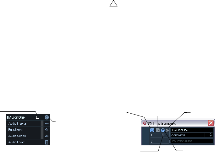
101
VST Instruments and Instrument tracks
4. If you now look in the Project window Track list, you
will find that a dedicated folder for the chosen instrument
has been added, within a “VST Instruments” folder (where
all your VST Instrument channels will be listed).
The separate folder for the added VST Instrument contains two types of
automation tracks: one for automating the plug-in parameters and one for
each mixer channel used by the VST Instrument. For example, if you add a
VST Instrument with four separate outputs (four separate mixer channels),
the folder will contain five automation tracks. To keep the screen less clut-
tered, you may want to close the folder for the VST Instrument until you
need to view or edit any of the automation tracks. For details about auto-
mation, see the chapter “Automation” on page 108.
•When you select the MIDI track routed to the VST in-
strument, you will see that the Inspector contains a sepa-
rate section for the instrument.
This section contains the audio channel settings for the VST Instrument
(inserts, EQs, Sends and fader settings). The tab has two buttons for
opening the Channel Settings window (for the VST Instrument channel)
and the Edit Instrument button which opens the control panel for the VST
Instrument.
5. Depending on the selected VST Instrument, you may
also need to select a MIDI channel for the track.
For example, a multitimbral VST Instrument can play back different
sounds on different MIDI channels – check the documentation for the
VST Instrument for MIDI implementation details.
6. Make sure the option “MIDI Thru Active” is activated in
the Preferences dialog (MIDI page).
7. Activate the Monitor button for the MIDI track (in the
Track list, Inspector or mixer).
When this is activated (or when the track is record enabled), incoming
MIDI is passed on to the selected MIDI output (in this case the VST In-
strument), see the chapter “Recording” on page 48.
8. Open the mixer.
You will find one or more channel strips for the audio outputs of the VST
Instrument. VST Instrument channel strips have the same features and
functionality as group channel strips, with the addition of an Edit button at
the bottom of the strip for opening the VST Instrument control panel. In
the Inspector you will also find an Output Routing pop-up menu for rout-
ing the VST instrument, e.g. to an output channel or group. Routing is de-
scribed in detail in the chapter “VST Connections: Setting up input and
output busses” on page 9.
9. Play the VST Instrument from your MIDI keyboard.
You can use the mixer settings to adjust the sound, add EQ or effects, etc.,
just as with regular audio channels. Of course, you can also record or man-
ually create MIDI parts that play back sounds from the VST Instrument.
•VST Instrument channels give you full access to multi-
timbral instruments.
You can have several MIDI tracks routed to the VST Instrument, each
playing a different part.
•Similarly, you can route channels to any available output
provided by the VST Instrument.
The VST Instruments window
When a VST Instrument is loaded, six controls are dis-
played for this slot in the VST Instruments window.
•The On/Off button is used to activate or deactivate the
VST Instrument.
When an instrument is selected from the instrument pop-up menu, it is
activated automatically, i.e. the on/off control lights up in blue.
For some instruments you may also bypass the instrument by clicking the
Bypass button to the right of the on/off button.
•Click the Edit (“e”) button to open the control panel for
the VST Instrument.
•Below the Edit button is a small LED that will light up
when MIDI data is received by the instrument.
•The rightmost button allows you to activate the desired
output for the instrument.
This is useful when you are using VST Instruments that have a large num-
ber of audio busses, which may be confusing. Click one of the entries in
the pop-up list to activate/deactivate output busses for this instrument.
Opens the Channel
Settings window.
Opens the control
panel for the VST
Instrument.
!
You can have up to 2 VST Instruments activated at the
same time, either different instruments or two in-
stances of the same instrument.
Instrument
on/off Activate
outputs
Bypass
instrument
Open instrument panel
Event received
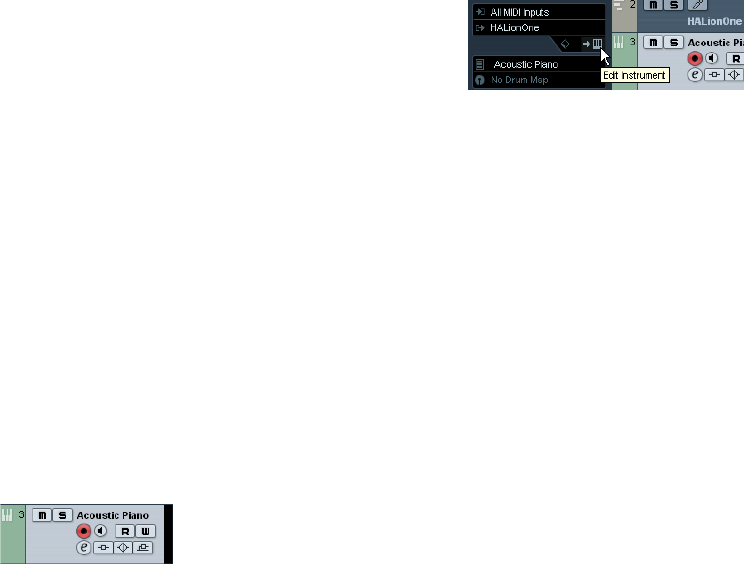
102
VST Instruments and Instrument tracks
Instrument tracks
An instrument track is a combination of a VST Instrument, a
MIDI track, and a VST Instrument channel, in other words:
it is a track coupled with a sound – it allows you to think in
terms of sounds rather than in terms of track and instru-
ment settings.
Adding Instrument tracks
To open and use an Instrument track, proceed as follows:
1. Open the Project menu and select Instrument from the
Add Track submenu.
You can also right-click in the Track list and select “Add Instrument
Track” on the context menu.
2. The Add Instrument Track dialog is opened.
You can select an instrument for the track from the pop-up (but you can
also leave this until later if you wish). Specify the number of instrument
tracks you wish to create in the “count” field. If you click the “Browse
Presets” button, the dialog expands to show the Presets browser, where
you can browse for sounds.
3. Click OK to add the Instrument track.
When you select an Instrument in the Add Track dialog, the new track
will get the name of the instrument. When no instrument is selected, the
track is named “Instrument track”.
An instrument track in the Track list
Properties
•Each Instrument track has a corresponding channel
strip in the mixer.
•In the Inspector, you can select a VST Instrument from
the Instrument pop-up menu.
When you select an instrument from this pop-up, its control panel will
open automatically.
•You can also exchange the “sound” of an instrument
track (i.e. the VST Instrument and its settings) by extract-
ing these data from another instrument track or a VST pre-
set, see “Extracting sound from an instrument track or VST
preset” on page 158.
•On the Input Routing pop-up menu, you can select a
MIDI input.
Instrument tracks have only one MIDI input.
•To open the control panel for the VST Instrument, click
the “Edit Instrument” button in the Inspector.
•As with MIDI tracks, you can perform the usual MIDI edit-
ing procedures on the instrument track, like duplicate, split,
or repeat the track, drag and drop the MIDI parts of an in-
strument track etc. For more information, see the chapter
“MIDI realtime parameters” on page 166.
•As with the MIDI track inspector and track controls, you
can adjust track delay, choose MIDI input, work with VST
Instrument panels, choose drum maps etc. For more infor-
mation, see the chapter “MIDI realtime parameters” on
page 166.
•Instrument tracks have all options that VST Instrument
channels have, i.e. Inserts, Sends, EQ, etc.
ÖVST Instruments used in Instrument tracks do not ap-
pear in the VST Instruments window.
For an overview of all used VST Instruments, open the Plug-in Information
window via the Devices menu. For further information, see the section “The
Plug-in Information window” on page 97.
Restrictions
•MIDI volume and pan cannot be controlled (there is no
“MIDI fader” tab in the Inspector); instead, the VST Instru-
ment volume and pan are used (via the “Channel” tab in the
Inspector). This applies also to the respective automation
parameters.
ÖDue to there being only one volume and pan control for
the instrument track, the Mute button will mute the com-
plete track including the VST Instrument. (As opposed to a
MIDI track with an assigned VST Instrument, for which mut-
ing the MIDI track still allows you to monitor and record the
VST Instrument.)
•Instrument tracks always have one stereo output chan-
nel only. This means that VST Instruments that do not pro-
vide a stereo output as their first output channel cannot be
used with instrument tracks, and must be loaded via the
VST Instruments window.
103
VST Instruments and Instrument tracks
•Due to the limitation to one output channel, instrument
tracks play only the first voice of a multi-timbral VST In-
strument. If you want to use all voices, you have to load the
instrument via the VST Instruments window and set up a
MIDI channel to play it.
Exporting instrument tracks as MIDI file
You can also export instrument tracks as standard MIDI
files, see “Exporting MIDI files” on page 259.
Please note:
•As there is no MIDI patch information in an instrument
track, this information is missing in the resulting MIDI file.
•If you activate “Export Inspector Volume/Pan”, volume
and pan information of the VST Instrument will be con-
verted and written into the MIDI file as controller data.
What do I need? Instrument channel
or Instrument track?
•If you need a particular sound without knowing which
VST Instrument to use, create an instrument track and use
the preview features to find the sound you want.
•Do likewise if the Instrument track restrictions described
above do not matter.
•If you are planning to create an instrument track preset,
complete with inserts and EQ settings, you have to use an
instrument track.
•If you need to use multitimbral parts and/or multiple out-
puts, set up a VST Instrument channel.
VST instruments and processor load
If you are working with VST 3 instruments, another way to
relieve processor load is the option “Suspend VST3 plug-in
processing when no audio signals are received” in the Pre-
ferences dialog (VST–Plug-ins page). This is described in
the section “Smart plug-in processing” on page 86.
Using presets for VSTi configuration
About track presets and VST presets
Track presets and VST presets allow you to quickly set up
tracks or instruments with all the settings required for the
sound you want. Cubase AI provides various types of pre-
sets for various purposes. Two of these are of relevance
for VST Instruments:
•Track presets for instrument tracks store the parameter
settings of a VST Instrument together with all track/chan-
nel settings (applied audio insert effects, etc.).
Instrument track presets can only be applied to instrument tracks, not to
instrument channels activated in the VST Instruments window.
•VST presets store all panel settings for a plug-in (VST In-
struments and VST effects), but no track/channel settings.
Note that you can create instrument tracks from VST 3 presets, i.e. se-
lecting a VST 3 preset will create an instrument track with all settings
stored in the VST preset plus an “empty” track.
As described in the chapter “Audio effects” on page 85,
there are two types of VST presets that can be used: the
VST 2 standard “.fxb/.fxp” files and the VST 3 preset stan-
dard with the extension “.vstpreset”. Some of the included
VST Instruments use the VST 2 preset standard, and oth-
ers use the VST 3 standard.
All VST 2 instruments can import “.fxb/.fxp” files and also
convert them to the VST 3 standard. Once converted, you
can use all VST 3 features, see “About earlier VST Instru-
ment presets” on page 106.
ÖFor further information on Track presets and VST pre-
sets, see the chapter “Working with Track Presets” on
page 155.
Browsing for sounds
One important and often time-consuming aspect of music
creation is the search for the right sounds. You might spend
a huge amount of time trying out the presets for a particular
instrument only to find out later that the preset for another
instrument contains the sound you were looking for.
This is why Cubase AI features extensive browsing possi-
bilities, allowing you to preview all available presets without
having to load them first!
In addition, you can filter your search by specifying cate-
gory, style, etc.
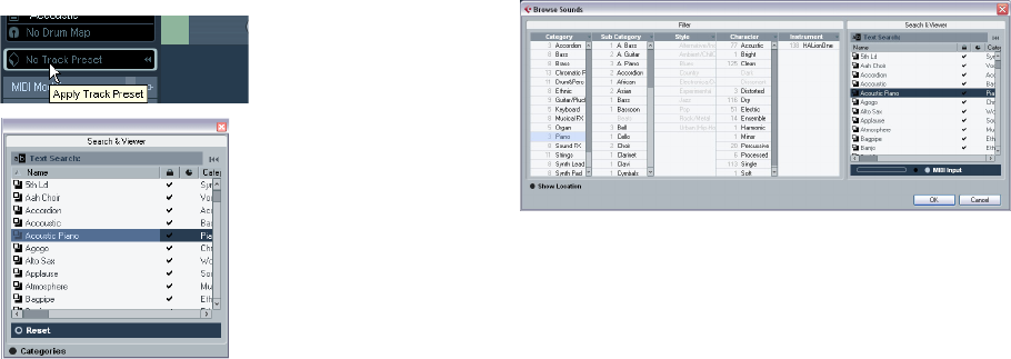
104
VST Instruments and Instrument tracks
For example, if you are looking for a bass sound, simply
select the Bass category and you can browse and preview
all bass sounds for all instruments. If you know you want a
synth bass sound, select Synth Bass as sub-category and
all synth bass sounds will be shown, etc.
You can also browse and preview track presets for instru-
ment tracks, i.e. instrument sounds plus all track settings
and all channel insert effect settings for this track.
These features combined speed up the process of finding
the right sound immensely.
•When creating your own presets, it is always a good
idea to set up attributes for them, as it allows you to fully
use the browsing features for your files, too.
There are two ways of browsing for sounds:
•Using the Presets browser.
This will apply preset settings to an existing track.
•Using the Browse Sounds dialog.
Use this dialog if you have not set up a track yet.
Using the Presets browser
1. Create an instrument track and select it in the Track list.
You do not have to assign an instrument to the track, but make sure to
specify a MIDI input.
2. Make sure that the track settings are shown in the
Inspector.
3. Click in the Track Preset field in the Inspector (the text
field currently reads “No Track Preset”).
4. The Presets browser is opened. It contains three sec-
tions (Browser, Search & Viewer and Filter). By default, only
the Search & Viewer section is shown. Note that it may take
a moment before all available sounds appear in the Viewer.
•The Viewer section to the right displays all track presets
for instrument tracks and all VST 3 presets.
Track presets for audio tracks, MIDI tracks or “multi” track setups are not
displayed. The preset icon to the left of the file name indicates the type of
preset.
5. Select a preset in the list.
6. Play a few notes on your MIDI keyboard to hear the
preset sound. You can switch between presets and hear
the sound when you play. You can also play back/loop a
MIDI part on a track. Each time you select a preset, all as-
sociated track and/or instrument settings are automati-
cally loaded.
7. Use the Filter section to search for specific attributes if
you wish.
You can click on the attributes in the respective column (Category, Style
etc.), to filter out all presets that do not match the selected attribute(s).
8. Double-click the desired preset to select it and close
the dialog.
Using the “Browse Sounds” dialog
1. Open the Project menu–Add Track submenu and se-
lect “Browse Sounds…”.
The Browse Sounds dialog is opened. It contains the same sections as the
Apply Track Presets dialog (Browser, Viewer and Filter).
The Viewer section of the Browse Sounds dialog displays
all preset sounds for all track types and all VST Instru-
ments. To preview the presets, you have play MIDI notes
on your MIDI keyboard because at this stage there is no
track connected.
Click here…
…to open the Presets browser.
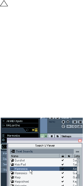
105
VST Instruments and Instrument tracks
2. When you have found the right sound, click OK to
close the dialog.
An instrument track is created with all track and/or instrument settings
that were saved in the preset.
Selecting VST Instrument presets
The previous sections focussed on selecting presets for
the creation of new instrument tracks, or for changing the
setup of an existing track. However, you can also use pre-
sets to change the settings of a VST Instrument.
To select a VST Instrument preset, proceed as follows:
1. Load a VST Instrument (either in the VST Instruments
window or via an instrument track).
2. If you use the VST Instruments window, select a MIDI
track routed to the instrument. If you use an instrument
track, select this.
3. If necessary, click on the track name at the top of the
Inspector to open the basic track settings.
4. Click in the Programs field in the Inspector.
The Presets browser is opened.
5. Step through the presets during playback to find the
sound you are looking for.
6. Double-click the desired preset to load it and close
the Presets browser.
•You can also open the Presets browser by clicking in
the preset name field in the control panel of a VST Instru-
ment or by clicking the button next to the Preset name in
the control panel and selecting “Load Preset…” from the
pop-up menu.
•Selecting another preset in the Presets browser will
load it directly, replacing the previous preset.
•When the Presets browser is open, you can still use
Project window key commands, allowing you to start/stop
playback or locate to different positions in the project.
•Clicking the Reset button below the Viewer will reload
the last loaded preset.
Saving VST Instrument presets
You can save your settings as presets for further use (e.g.
in other projects):
1. In the VST Instrument panel, click the button to the right
of the preset name and select “Save Preset…” from the
pop-up menu.
This opens a dialog where you can save the current settings as a preset.
Presets are saved into a default folder named VST3 Pre-
sets. Within this folder, there is a folder called “Steinberg
Media Technologies” where the included presets are ar-
ranged in subfolders named after each instrument.
You cannot change the default folder, but you can add fur-
ther subfolders inside the instrument’s preset folder.
•Under Windows XP, the default preset folder is in the
following location: \Documents and Settings\<user
name>\Application data\VST3 Presets.
•Under Windows Vista, the default preset folder is in the
following location: \Users\<user name>\AppData\Roam-
ing\VST3 Presets.
•Under Mac OS, the default preset folder is in the follow-
ing location: /Users/<user name>/Library/Audio/Presets/
<company>/<plug-in name>.
2. Enter a name for the new preset in the File name field
in the lower part of the dialog.
•If you wish to assign attributes to the preset, click the
Tag Editor button.
Click in the Value column to select an appropriate “tag” for one or sev-
eral of the available categories in the Attributes column.
3. Click OK to store the preset and exit the dialog.
!
Note that the following refers to the selection of VST 3
presets (.vstpreset). If you want to apply .fxp/.fxb pre-
sets to your VST 2 instruments in this way, see “About
earlier VST Instrument presets” on page 106.
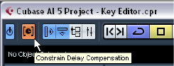
106
VST Instruments and Instrument tracks
Extracting sounds from Track Presets
You can extract a sound from a Track preset (disregarding
any track/channel settings) and save it as a VST preset.
Proceed as follows:
1. Click the button “Extract sound from Track Preset” be-
low the Output Routing pop-up menu in the Inspector.
This opens a dialog where all Track Presets are shown.
2. Select an instrument track preset or VST preset by
double-clicking it.
The VST Instrument and the settings (but no inserts, EQs or modifiers) of
the existing track are overwritten using the data of the track preset. The
previous VST Instrument for this instrument track is removed and the
new VST Instrument with its settings is set up for the instrument track.
Track Presets are described in detail in the chapter
“Working with Track Presets” on page 155.
About earlier VST Instrument presets
You can use any VST 2.x Instrument plug-ins in Cubase AI.
Installing VST Instrument plug-ins works the same way as
for audio effects – see “Installing additional VST plug-ins”
on page 96.
When you install a VST 2 instrument, any previously stored
presets for it will be of the old FX program/bank (.fxp/.fxb)
standard. You can import such files, but the preset handling
will be slightly different. You will not be able to use the new
features like the Preview function until you have converted
the old “.fxp/.fxb” presets to VST 3 presets. If you save new
presets for a VST 2 plug-in these will automatically be
saved in the new “.vstpreset” format in the default location.
Importing and converting FXB/FXP files
To import .fxp/.fxb files, proceed as follows:
1. Load any VST 2 instrument you may have installed, and
click on the VST Sound button to open the Preset Ma-
nagement pop-up menu.
2. Select “Import FXB/FXP” from the pop-up menu.
This menu item is only available for VST 2 instrument plug-ins.
3. In the file dialog that opens, locate the .fxp file and
click “Open”.
If you load a bank (.fxb), it will replace the current set of all effect programs.
If you load a single program, it will replace the currently selected effect pro-
gram only. Note that such files exist only if you created your own .fxp/fxb
presets with a previous program version (or any other VST 2 application).
•After importing, you can convert the current program list
to VST presets by selecting “Convert Program List to VST
Presets” from the Preset Management pop-up.
When the presets are converted, they will be available in the Presets
browser. The presets will be stored in the VST3 Preset folder.
About latency
Depending on your audio hardware and its ASIO driver,
the latency (the time it takes for the instrument to produce
a sound when you press a key on your MIDI controller)
may simply be too high to allow comfortable realtime VST
Instrument playback from a keyboard.
If this is the case, a workaround is to play and record your
parts with another MIDI sound source selected, and then
switch to the VST Instrument for playback.
ÖYou can check the latency for your audio hardware in
the Device Setup dialog (VST Audio System page).
The input and output latency values are shown below the ASIO Driver
pop-up menu. For live VST Instrument playing, these values should ide-
ally be a few milliseconds (although the limit for “comfortable” live playing
is a matter of personal taste).
Constrain Delay Compensation
Cubase AI features full delay compensation throughout
the entire audio path. This means that any delay inherent in
the VST plug-ins you use will automatically be compen-
sated for during playback, so that all channels are kept in
perfect sync (see “About plug-in delay compensation” on
page 87).
However, when you play a VST Instrument in realtime or
record live audio (with monitoring through Cubase AI acti-
vated), this delay compensation may sometimes result in
added latency. To avoid this, you can activate the Con-
strain Delay Compensation button on the Project window
toolbar. This function tries to minimize the latency effects
of the delay compensation, while maintaining the sound of
the mix as far as possible.
107
VST Instruments and Instrument tracks
•In the Preferences dialog (VST page) you will find a set-
ting called Delay Compensation Threshold. Only plug-ins
with a delay higher than this setting will be affected by the
Constrain Delay Compensation function.
•VST plug-ins (with higher delay than the threshold value)
which are activated for VST Instrument channels, audio
track channels that are record enabled, group channels and
output channels will be turned off when you activate Con-
strain Delay Compensation.
•VST plug-ins activated for FX channels are not turned
off but their delay is disregarded by the program (delay
compensation is turned off).
After recording or using a VST Instrument with Constrain
Delay Compensation, you should turn off the function to
restore full delay compensation.
10
Automation
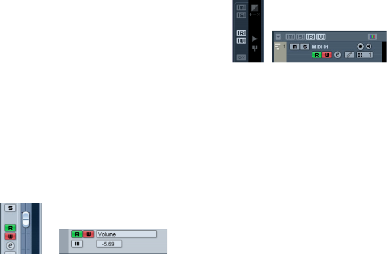
109
Automation
Introduction
In essence, automation means finding and recording, for
each and every moment of your project, the right values for
a particular mixer parameter. When you create your final
mix, you will not have to worry about having to adjust this
particular parameter control yourself – Cubase AI will do it
for you.
Cubase AI provides very powerful and yet intuitive auto-
mation of virtually every mixer and effect parameter.
The following sections provide detailed descriptions of the
Cubase AI automation features.
Enabling and disabling the writing
of automation data
Tracks and mixer channels in Cubase AI can be “automa-
tion enabled” by activating their automation Write (W)
buttons.
The following track types feature Write (W) and Read (R)
buttons in the mixer, in the Track list and in the Channel
Settings window: Audio, MIDI, Instrument, FX Channel
and Group Channel tracks. Furthermore, the control pan-
els for all plug-in effects and VST Instruments also feature
Write and Read buttons.
•If you activate Write for a channel, virtually all mixer pa-
rameters you adjust during playback for that specific
channel will be recorded as automation events.
•If Read is activated for a channel, all your recorded
mixer actions for that channel will be performed during
playback, just like you performed them in Write mode.
•The W and R buttons for a track in the Track list are mir-
rors of the W and R buttons in the corresponding channel
strip in the mixer.
ÖNote that the Read button is automatically enabled
when you enable the Write button. This allows Cubase AI
to read existing automation data at any time.
You can separately deactivate Write, if you want to only read existing
data. There is no status Write on/Read off.
There are also global Read and Write indicator buttons
(“All Automation to Read/Write Status”) in the common
panel of the mixer and at the top of the Track list:
These buttons light up as soon as there is a single en-
abled Read or Write button on any channel/track within
your project.
•When “All Automation to Read/Write Status” is dis-
abled and you click on one of these buttons, all Read/
Write buttons on all tracks/channels are enabled.
When “All Automation to Read/Write Status” is enabled, this means that
at least one of the Read/Write buttons on one of the channels of your
project is enabled.
•When “All Automation to Read/Write Status” is enabled
and you click on one of these buttons, any enabled Read/
Write buttons on the tracks/channels of your project are
disabled.
Creating automation data
Within a Cubase AI project, the changes in a parameter
value over time are reflected as curves on so-called auto-
mation tracks. The curves are drawn in realtime while you
write the automation data. Most of the tracks in your
project have automation tracks, one for each automated
parameter.
ÖAutomation tracks are hidden by default. For informa-
tion on automation track handling, see the sections “Auto-
mation track operations” on page 111 and “Working with
automation curves” on page 114.
The Write and Read buttons for a channel in the mixer
and for an automation track in the Track list
The “All Automation to Read/Write Status” buttons in the
mixer, and in the Track list
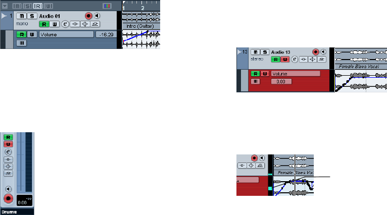
110
Automation
There are two approaches you can use to create automa-
tion curves:
•“Offline”, by manually drawing the curves on automation
tracks in the Project window.
See “Editing automation events” on page 115.
•“Online”, by enabling the Write button and adjusting
parameters in the mixer or channel settings window while
rolling through the project in realtime. The value settings are
recorded and displayed as a curve on the automation track.
In the following sections, this online writing of automation data is also re-
ferred to as an “automation pass”.
The methods are not different in terms of how the auto-
mation data is applied. They only differ in the way the au-
tomation events are created – manually drawing them or
recording them during automation passes. Any applied
automation data will be reflected in both the mixer (a fader
will move for example) and in a corresponding automation
track curve.
There are no hard and fast rules regarding which method
you should use. For example, you can create your automa-
tion data online without ever even opening an automation
track. Or you can stick to drawing automation curves off-
line. Every method has its advantages, but of course it is
up to you to decide what to use and when.
•Editing curves on automation tracks offers a graphical
overview in relation to the track contents and the time
position.
This makes it easy to quickly change parameter values at specific points,
without having to activate playback. For example, this method gives you a
good overview if you have a voice-over or a dialog on one track and a
music bed on another track, the level of which needs to be lowered by a
specific amount every time the dialog occurs.
•By using write automation in the mixer you do not have
to manually select parameters from the Add Parameter list.
You can work much like you would using a “real” physical mixer. Every
action you perform is automatically recorded on automation tracks which
you can later open for viewing and editing.
The automation tracks themselves indicate the writing of
automation data:
•While writing automation data, the color of the automa-
tion track in the Track list changes to red.
•The delta indicator in the automation track shows the
relative amount by which the new parameter setting devi-
ates from any previously automated value.
This is an additional visual aid when writing new automation data.
What can be automated?
You can automate virtually every parameter in the Cubase
AI mixer.
•To find out which parameters can be automated for a
particular track, click in the Parameter display of the auto-
mation track to open a pop-up menu. Select “More…” to
open the Add Parameter dialog.
This dialog lists all automatable parameters for a particular track type. It is
described in detail in the section “Assigning a parameter to an automa-
tion track” on page 112.
Options and Settings
About the Automation Reduction Level preference
This item can be found on the Editing page in the Prefer-
ences dialog. The automation reduction function automati-
cally reduces the number of automation events. During an
automation pass (or when drawing automation with the
Pencil tool), these are added as a continuous stream of
densely packed break-points. This is necessary because
the program cannot “guess” what you will be doing next.
The delta indicator
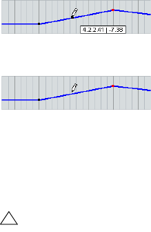
111
Automation
However, when punching out, the reduction function will
remove all break-points that are not needed. The automa-
tion curve will contain only the break-points necessary to
reproduce your actions.
For example, all break-points that lie between two other
points, but do not deviate from the curve, will be automat-
ically removed by reduction.
If you try to add a break-point that does not deviate from the existing
curve between two existing points…
…it will be removed when the mouse is released. If you move the se-
lected break-point by any amount so that the resulting curve is not a
straight line, a new event will be added.
•If you are unhappy with the default setting (a reduction
of roughly 50%), you can change it, but normally the de-
fault setting works well.
Hints and further options
Automation key commands
In the Key Commands dialog (opened from the File menu
in Cubase AI), in the Commands section on the left, you
will find an Automation category which lists all automation
commands to which you can assign key commands.
How to assign key commands is described in detail in the
chapter “Key commands” on page 268.
About linking and automation
•Cubase AI allows you to link, in the mixer window, vari-
ous parameters between different channels (see “Link/
Unlink channels” on page 82).
When automating the settings of a channel that is linked to another
channel in the mixer, the parameters of the linked channel will NOT be
automated.
About automation undo
Every automation write operation you perform creates its
own event in the undo history, so you can undo or redo
any of your automation moves at any time.
Automation track operations
About automation tracks
Audio tracks, group channel tracks and FX channel tracks
all have automation tracks. These allow you to view and edit
the automation of all mixer settings for the track, including
settings for the track’s insert effects. There is one automa-
tion track for each parameter, and automation tracks can be
shown or hidden in any combination.
Similarly, MIDI tracks have automation tracks for mixer set-
tings, track parameters and (if used) for send and insert ef-
fect settings.
VST Instruments have special automation tracks that ap-
pear in the Project window when you load a VST Instrument
via the VST Instruments window. There is one automation
track for the plug-in parameters, and one track for each
mixer channel used by the instrument. These tracks have
automation subtracks, giving you access to all parameters
and mixer settings.
Instrument tracks, as a combination of a MIDI track and a
VST Instrument, have automation tracks that provide auto-
mation parameters for the VST Instrument itself, for the
VST Instrument channel and the respective MIDI automa-
tion parameters.
Opening automation tracks
Every track has one automation track, showing one auto-
mation parameter.
For audio, Instrument, group channel, MIDI and FX chan-
nel tracks, there are two ways you can open an automa-
tion track for the channel:
•By right-clicking the track in the Track list and selecting
“Show Automation” from the context menu.
!
The higher the number of automation events, the
higher the CPU load. If performance is an issue in
your workflow, you should consider raising the re-
duction level, to remove more events.
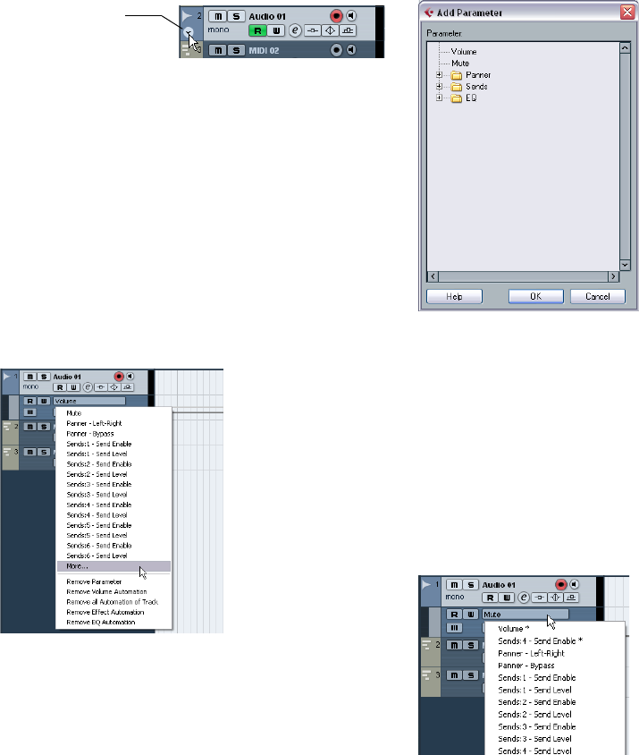
112
Automation
•By clicking along the left edge of the track in the Track
list. (Also, when you position the mouse pointer over the
lower left corner of the track, a corresponding arrow icon
(“Show/Hide Automation”) appears.)
An automation track opens in the Track list. When you open an automa-
tion track for the first time, the Volume parameter is selected by default.
Assigning a parameter to an automation track
Default parameters are already assigned to automation
tracks when you open them, according to their order in the
Add Parameter list (see below).
To select which parameter an open automation track
should display, proceed as follows:
1. If none exists, open an automation track using one of
the methods described above.
2. Click in the parameter display for the automation track.
A pop-up list is shown, containing some of the automation parameters
plus the item “More…” at the bottom of the list. The contents of the list
depend on the track type.
•If the parameter you wish to automate is on the pop-up
menu, you can select it directly.
The parameter will then replace the current parameter in the automation
track.
•If you wish to add a parameter not available on the pop-
up menu or want to view all parameters that can be auto-
mated, go on to the next step.
3. Select “More…”.
The Add Parameter dialog appears. This dialog shows a list with all pa-
rameters that can be automated for the selected channel (sorted into dif-
ferent categories), including the parameters for any assigned insert
effects. To view the parameters in each category, click the “+” sign for
the category folder.
The Add Parameter dialog for an audio track
4. Select a parameter from the list and click OK.
The parameter will then replace the current parameter in the automation
track.
ÖNote that the “replacing” of the parameter displayed in
the automation track is completely non-destructive.
If the automation track contained any automation data for the parameter
you just replaced, this data will still be there, although it will not be visible
after you replaced the parameter. If you click in the parameter display you
can switch back to the replaced parameter. On the pop-up menu, all au-
tomated parameters are indicated by an asterisk (*) after the parameter
name.
The first two parameters are automated.
Click here to open an
automation track.
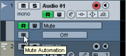
113
Automation
Removing automation tracks
To remove all automation for the selected parameter, click
the parameter name and select “Remove Parameter” from
the pop-up menu. This will delete any automation events
on the automation track, and the track will be closed.
Hiding automation tracks
•To hide a single automation track, position the pointer
over the top left border of the automation track in the
Track list and click the “Hide Automation Track” button
(the minus sign).
•To hide all automation tracks for all tracks in the Track
list, right-click any track and select “Hide All Automation”
from the context menu.
Muting automation tracks
You can mute individual automation tracks by clicking their
Mute buttons in the Track list. Unlike the Read (R) button,
which will activate or deactivate Read mode for all auto-
mation tracks of a track, the Mute button allows you to turn
off automation for a single parameter.
The “Automation follows Events” setting
If you activate “Automation follows Events” on the Edit
menu (or in the Preferences–Editing page), automation
events will automatically follow when you move an event or
part on the track.
This makes it easy to set up automation related to a spe-
cific event or part, rather than to a specific position in the
project. For example, you can automate the panning of a
sound effect event (having the sound pan from left to right,
etc.) – if you need to move the event, the automation will
automatically follow! The rules are:
•All automation events for the track between the start
and end of the event or part will be moved.
If there are automation events in the new position (to which you move the
part or event), these will be overwritten.
•If you copy an event or part, the automation events will
be duplicated as well.
Recording your actions – an example
If the settings in your current project are crucial, you may
not want to “experiment” with automation until you know
more about how it all fits together. If so, you can create a
new project for the following example. It does not even
have to contain any audio events, just a few audio tracks.
Proceed as follows:
1. Open the Mixer window.
2. Click the global Write button (“All Automation to Write
Status”) in the mixer common panel.
Cubase AI is now in global Write mode.
3. Start playback and adjust some volume faders and/or
other parameter settings in the mixer or perhaps in a
Channel Settings window.
Stop playback when you are done, and return to the position where you
started playback.
4. Deactivate Write mode and click the global Read but-
ton (“All Automation to Read Status”) in the mixer com-
mon panel.
Cubase AI is now in global Read mode.
5. Start playback, and watch the Mixer window.
All your actions performed during the previous playback will be repro-
duced exactly.
6. If you wish to redo anything that was recorded, acti-
vate Write mode again and start playback from the same
position.
•You can have Write and Read activated simultaneously,
if you want to watch and listen to your recorded mixer ac-
tions while you’re recording fader movements for another
mixer channel, etc.
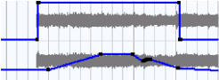
114
Automation
Recording plug-in automation
Every parameter for every assigned effect or VST Instru-
ment can be automated in much the same manner as de-
scribed above.
The following example assumes that you have assigned an
insert effect to an FX channel track (see the chapter “Au-
dio effects” on page 85), and describes how to record au-
tomation for the effect:
1. Select the FX channel track in the Track list and open
its Inserts section in the Inspector.
2. Open the control panel for the effect by clicking the Edit
button (“e”) above the insert effect slot in the Inspector.
3. Click the Write button in the control panel to enable
Write mode.
The Read button is enabled as well. All effects and VST Instruments have
Write/Read buttons on their control panels. These work exactly like the
corresponding buttons in the mixer or in the Track list.
4. Start playback and adjust some effect parameters in
the control panel.
When you are finished, stop playback and return to the position where
you started playback.
5. Disable Write.
The Read button remains enabled.
6. Start playback and watch the control panel.
All actions you performed during the previous playback will be repro-
duced exactly.
Dragging and dropping of insert plug-ins
You can drag an insert plug-in from one insert slot to an-
other, either on the same channel or on a different channel.
•When dragging a plug-in to a different insert slot on the
same channel, any existing automation data will move with
the plug-in.
•When dragging a plug-in to a different insert slot on a
different channel, any existing automation data will not be
transferred to the new channel.
Where did the automation data I recorded end
up?
When using global Write automation, you can write auto-
mation data on the automation tracks of all channels. In
the previous write operations, you probably added auto-
mation events for many different channels and parameters.
•To view all the automation events you recorded during
the operations, select “Show All Used Automation” from
the Project menu or from the Track list context menu.
For each of the channels one subtrack with automation data is now
shown in the Project window. The automation events recorded are
shown as points in the automation curves.
Working with automation curves
About automation curves
There are two kinds of automation curves, “ramp” and
“jump”:
•Jump curves are created for any parameter that only has
on/off values, like a Mute button, for example.
•Ramp curves are created for any parameter that gener-
ates continuous multiple values, such as fader or encoder
movements, etc.
Examples of jump and ramp automation curves
About the static value line
When you open an automation track for a parameter for the
first time, it does not contain any automation events (unless
you have previously adjusted that parameter with write au-
tomation activated), and this is reflected in the event display
as a straight horizontal black line, the “static value” line. This
line represents the current parameter setting.
•If you have manually added any automation events or
used write automation for the corresponding parameter,
and then disable the reading of automation data, the auto-
mation curve will be grayed-out in the automation track
event display and the static value will be used instead.
As soon as Read mode is enabled, the automation curve will become
available.
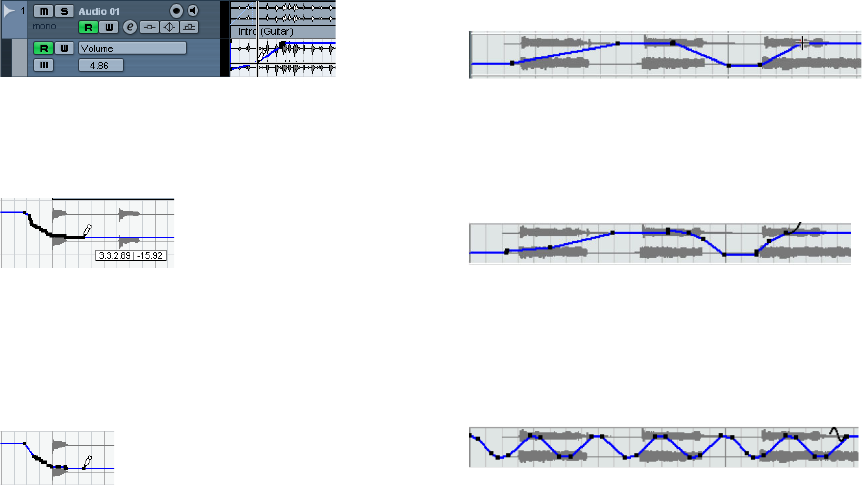
115
Automation
Editing automation events
Drawing automation events
By using write automation in the mixer, you generate auto-
mation events by moving parameter encoders and faders
in the mixer. You can also add them manually by drawing
automation curves on an automation track. Proceed as
follows:
1. Open an automation track for the track you want to
make settings for.
The static value line is shown in the event display for the automation track
and the Volume parameter is selected.
2. Select the Pencil tool.
You can also use the various modes of the Line tool for drawing curves,
see below.
3. Click on the static value line. An automation event is
added, read automation mode is automatically activated,
and the static value line changes to a blue automation
curve.
4. If you click and hold, you can draw a curve by adding a
multitude of single automation events.
Note that the track color in the Track list changes to red to indicate that
automation data is being written.
5. When you release the mouse button, the number of
automation events is reduced to a few events, but the ba-
sic shape of the curve still remains the same.
This “thinning out” of events is governed by the Reduction Level setting
in the Preferences dialog, see “About the Automation Reduction Level
preference” on page 110.
6. If you now activate playback, the volume will change
with the automation curve.
In the mixer, the corresponding fader moves accordingly.
7. Simply redo the operation if you are not happy with the
result.
If you draw over existing events, a new curve is created.
•If the automation track is in Read mode already, you can
also add automation events by clicking with the Arrow
tool.
If you are trying to add a break-point between two existing points and the
new point does not deviate from the existing curve, it will be removed by
reduction as soon as you release the mouse button (see “About the Au-
tomation Reduction Level preference” on page 110).
Using the various modes of the Line tool to draw
automation curves
The Line tool can be very useful for drawing automation
events. The various modes are accessed by selecting the
Line tool on the toolbar, clicking on it a second time and
selecting from the pop-up menu that appears.
•Clicking and dragging with the Line tool in Line mode
shows a line in the automation track and creates automa-
tion events aligned with this line.
This is a quick way to create linear fades, etc.
•The Line tool in Parabola mode works in the same way,
but aligns the automation events with a parabolic curve in-
stead, resulting in more “natural” curves and fades.
Note that the result depends on the direction from which you draw the
parabolic curve.
•The Sine, Triangle and Square Line tool modes create
automation events aligned with continuous curves.
If snap is activated and set to Grid, the period of the curve (the length of
one curve “cycle”) is determined by the grid setting. If you press [Shift]
and drag, you can set the period length manually, in multiples of the grid
value.
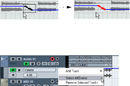
116
Automation
Selecting automation events
•To select a single automation break-point, click on it
with the Arrow tool.
The break-point turns red, and you can drag it in any horizontal or vertical
direction between two points.
•To select multiple break-points, you can either [Shift]-
click or drag a selection rectangle with the Arrow tool.
All break-points inside the selection rectangle will be selected.
Drawing a selection rectangle around break-points to select them.
•To select all automation events on an automation track,
right-click the automation track in the Track list and choose
“Select All Events” from the context menu.
Removing automation events
There are several ways to remove break-points:
•By selecting points and pressing [Backspace] or [De-
lete] or selecting Delete from the Edit menu, or by clicking
on a break-point with the Erase tool.
This will remove the break-points. The curve is redrawn to connect the
break-points immediately to the left and right of the removed points.
•By selecting a range (with the Range Selection tool),
and pressing [Backspace] or [Delete] or selecting Delete
from the Edit menu.
•By clicking in the parameter display on an automation
track and selecting “Remove Parameter” from the pop-up.
This will remove all automation events from the automation track, and the
automation track will be closed.
Editing automation events
Automation events can be edited much like other events.
You can use cut, copy and paste, and nudge events, etc.
MIDI Part Data vs Track Automation
In Cubase AI, you can enter (or record) MIDI Controller
data in two ways: as automation data on an automation
track or as part data in the MIDI part. The following ap-
plies:
•When the Automation Read button for a track is en-
abled, controller data will be written as automation data on
an automation track in the Project window.
•When the Read button is disabled, the controller data
will be written in the MIDI part and can be viewed and ed-
ited for example in the Key Editor.
Nevertheless, you can end up with both kinds of controller
data for a MIDI part if you recorded controller part data in
one pass and automation data during another. In this case,
these “conflicting” data types will be combined during
playback as follows:
•Part automation only begins when the first controller
event within the part is reached. At the end of the part, the
last controller value will be kept until an automation break-
point is reached on the automation track.
11
Audio processing and functions
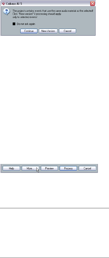
118
Audio processing and functions
Background
Audio processing in Cubase AI can be called “non-de-
structive”, in the sense that you can always undo changes
or revert to the original versions. This is possible because
processing affects audio clips rather than the actual audio
files, and because audio clips can refer to more than one
audio file. This is how it works:
1. If you process an event or a selection range, a new audio
file is created in the Edits folder, within your project folder.
This new file contains the processed audio, while the original file is unaf-
fected.
2. The processed section of the audio clip (the section
corresponding to the event or selection range) then refers
to the new, processed audio file.
The other sections of the clip will still refer to the original file.
•Since all edits are available as separate files, it is possi-
ble to undo any processing, at any point and in any order!
•Furthermore, the original, unprocessed audio file can still
be used by other clips in the project, by other projects or by
other applications.
Audio processing
Basically, you apply processing by making a selection and
selecting a function from the Process submenu on the Au-
dio menu. Processing is applied according to the follow-
ing rules:
•When events are selected in the Project window or the
Audio Part Editor, the processing will be applied to these
events only.
Processing will only affect the clip sections that are referenced by the
events.
•When an audio clip is selected in the Pool, the process-
ing will be applied to the whole clip.
•When you have made a selection range, the processing
will be applied to this range only.
Other sections of the clip are not affected.
If you attempt to process an event that is a shared copy
(i.e. the event refers to a clip that is used by other events in
the project), you are asked whether you want to create a
new version of the clip or not.
Select “New Version” if you want the processing to affect the selected
event only. Select “Continue” if you want the processing to affect all
shared copies.
ÖIf you activate “Do not show this message again”, any
further processing you do will conform to the selected
method (“Continue” or “New Version”).
You can change this setting at any time by using the “On Processing
Shared Clips” pop-up in the Preferences (Editing–Audio page). Also,
“Create New Version” will now be displayed as an option in the dialog for
the processing function.
Common settings and features
If there are any settings for the selected Audio processing
function, these will appear when you select the function
from the Process submenu. While most settings are spe-
cific for the function, some features and settings work in
the same way for several functions.
The “More…” button
If the dialog has a lot of settings, some options may be
hidden when the dialog appears. To reveal these, click the
“More…” button.
To hide the settings, click the button again (now labeled
“Less…”).
The Preview, Process and Cancel buttons
These buttons have the following functionality:
Button Description
Preview Allows you to listen to the result of the processing with the
current settings. Playback will continue repeatedly until
you click the button again (the button is labeled “Stop”
during Preview playback). You can make adjustments dur-
ing Preview playback, but the changes are not applied until
the start of the next “lap”. Some changes may automati-
cally restart the Preview playback from the beginning.
Process Performs the processing and closes the dialog.
Cancel Closes the dialog without processing.
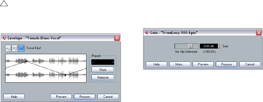
119
Audio processing and functions
Pre/Post-Crossfade
Some processing functions allow you to gradually mix the
effect in or out. This is done with the Pre/Post-Crossfade
parameters. If you activate Pre-Crossfade and specify a
value of e.g. 1000ms, the processing will be applied grad-
ually from the start of selection, reaching full effect 1000ms
after the start. Similarly, if you activate Post-Crossfade, the
processing will gradually be removed, starting at the speci-
fied interval before the end of the selection.
Envelope
The Envelope function allows you to apply a volume enve-
lope to the selected audio. The dialog contains the follow-
ing settings:
Curve Kind buttons
These determine whether the envelope curve should con-
sist of spline curve segments (left button), damped spline
segments (middle button) or linear segments (right button).
Envelope display
Shows the shape of the envelope curve. The resulting
waveform shape is shown in dark gray, with the current
waveform shape in light gray. You can click on the curve
to add points, and click and drag existing points to change
the shape. To remove a point from the curve, drag it out-
side the display.
Presets
If you have set up an envelope curve that you may want to
apply to other events or clips, you can store it as a preset
by clicking the Store button.
•To apply a stored preset, select it from the pop-up
menu.
•To rename the selected preset, double-click on the
name and enter a new one in the dialog that appears.
•To remove a stored preset, select it from the pop-up
menu and click Remove.
Fade In and Fade Out
For a description of these functions, see the chapter “Fa-
des, crossfades and envelopes” on page 62.
Gain
Allows you to change the gain (level) of the selected audio.
The dialog contains the following settings:
Gain
This is where you set the desired gain, between -50 and
+20dB. The setting is also indicated below the Gain dis-
play as a percentage.
Clipping detection text
If you use the Preview function before applying the pro-
cessing, the text below the slider indicates whether the
current settings result in clipping (audio levels above
0dB). If that is the case, lower the Gain value and use the
Preview function again.
•If you want to increase the level of the audio as much as
possible without causing clipping, you should use the Nor-
malize function instead (see “Normalize” on page 121).
Pre- and Post-Crossfade
See “Pre/Post-Crossfade” on page 119.
!
The sum of the Pre- and Post-Crossfade times can-
not be larger than the length of the selection.
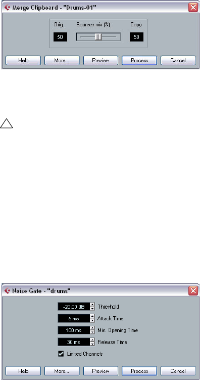
120
Audio processing and functions
Merge Clipboard
This function mixes the audio from the clipboard into the
audio selected for processing, starting at the beginning of
the selection.
The dialog contains the following settings:
Sources mix
Allows you to specify a mix ratio between the original (the
audio selected for processing) and the copy (the audio on
the clipboard).
Pre- and Post-Crossfade
See “Pre/Post-Crossfade” on page 119.
Noise Gate
Scans the audio for sections weaker than a specified
threshold level and replaces them with silence. The dialog
contains the following settings:
Threshold
The level below which you want audio to be silenced.
Levels below this value will close the gate.
Attack Time
The time it takes for the gate to open fully after the audio
level has exceeded the threshold level.
Min. Opening Time
This is the shortest time the gate will remain open. If you
find that the gate opens and closes too often when pro-
cessing material that varies rapidly in level, you should try
raising this value.
Release Time
The time it takes for the gate to close fully after the audio
level has dropped below the threshold level.
Linked Channels
This is available for stereo audio only. When it is activated,
the Noise Gate is opened for both channels as soon as
one or both channels exceed the Threshold level. When
Linked Channels is deactivated, the Noise Gate works in-
dependently for the left and right channel.
Dry/Wet mix
Allows you to specify a mix ratio between “dry” and pro-
cessed sound.
Pre- and Post-Crossfade
See “Pre/Post-Crossfade” on page 119.
!
For this function to be available, you need to have cut
or copied a range of audio in the Sample Editor first.
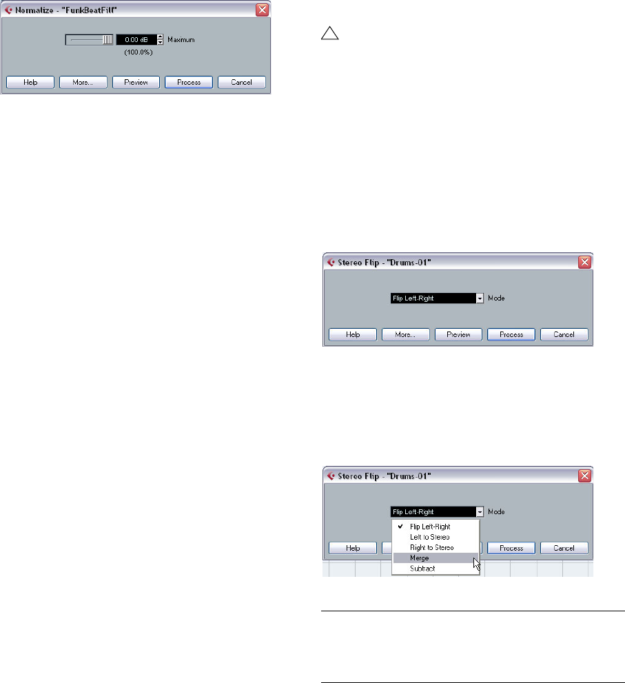
121
Audio processing and functions
Normalize
The Normalize function allows you to specify the desired
maximum level of the audio. It then analyzes the selected
audio and finds the current maximum level. Finally it sub-
tracts the current maximum level from the specified level
and raises the gain of the audio by the resulting amount (if
the specified maximum level is lower than the current max-
imum, the gain will be lowered instead). A common use for
Normalizing is to raise the level of audio that was recorded
at too low an input level. The dialog contains the following
settings:
Maximum
The desired maximum level for the audio, between -50 and
0dB. The setting is also indicated below the Gain display
as a percentage.
Pre- and Post-Crossfade
See “Pre/Post-Crossfade” on page 119.
Phase Reverse
Reverses the phase of the selected audio, turning the
waveform “upside down”.
The dialog contains the following settings:
Phase Reverse on
When processing stereo audio, this pop-up menu allows
you to specify which channel(s) should be phase-reversed.
Pre- and Post-Crossfade
See “Pre/Post-Crossfade” on page 119.
Remove DC Offset
This function will remove any DC offset in the audio selec-
tion. A DC offset is when there is too large a DC (direct
current) component in the signal, sometimes visible as the
signal not being visually centered around the “zero level
axis”. DC offsets do not affect what you actually hear, but
they affect zero crossing detection and certain process-
ing, and it is recommended that you remove them.
Reverse
Reverses the audio selection, as when playing a tape
backwards. There are no parameters for this function.
Silence
Replaces the selection with silence. There are no parame-
ters for this function.
Stereo Flip
This function works with stereo audio selections only. It al-
lows you to manipulate the left and right channel in various
ways.
The dialog contains the following parameters:
Mode
This pop-up menu determines what the function does:
!
It is recommended that this function is applied to
complete audio clips, since the DC offset (if any) is
normally present throughout the entire recording.
Option Description
Flip Left-Right Swaps the left and right channel.
Left to Stereo Copies the left channel sound to the right channel.
Right to Stereo Copies the right channel sound to the left channel.
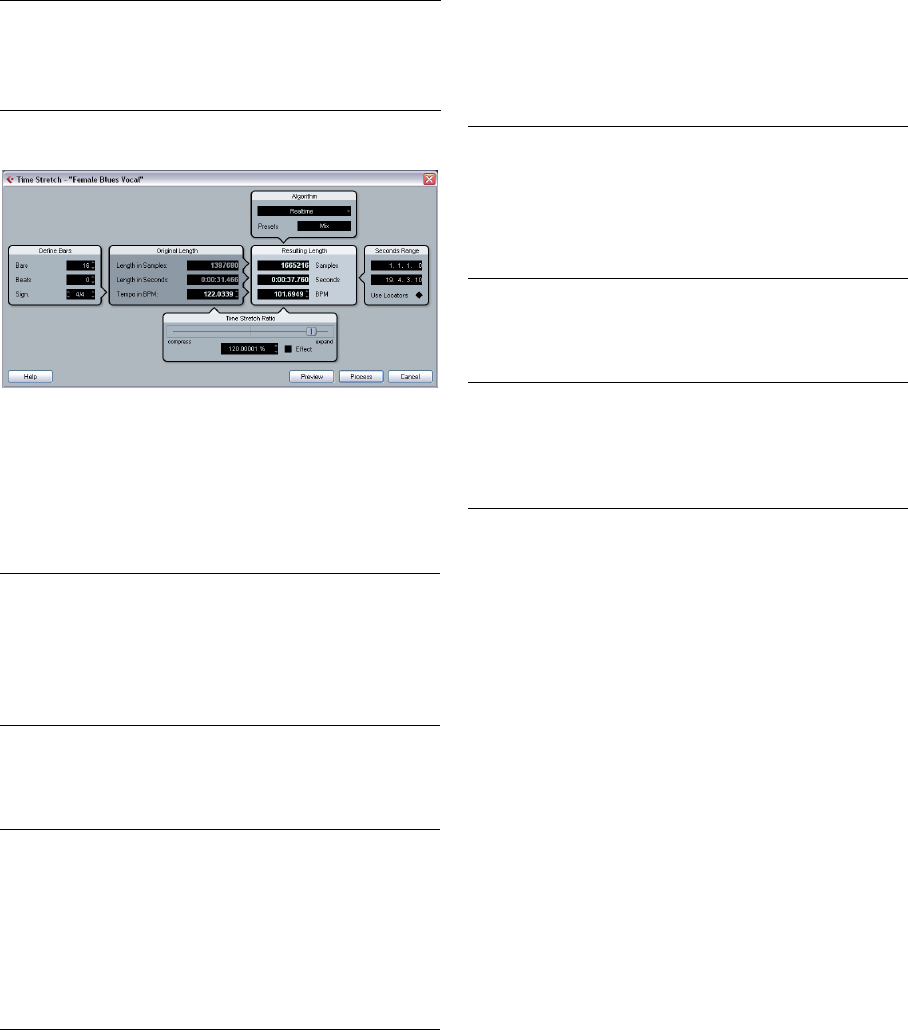
122
Audio processing and functions
Time Stretch
This function allows you to change the length and “tempo”
of the selected audio without affecting the pitch. The dia-
log contains the following parameters:
Define Bars section
In this section, you set the length of the selected audio
and the time signature:
Original Length section
This section contains information and settings regarding
the audio selected for processing:
Resulting Length section
These settings are used if you want to stretch the audio to
fit within a specific time span or tempo. The values will
change automatically if you adjust the Time Stretch Ratio
(see below).
Seconds Range section
These settings allow you to set the desired range for the
time stretch.
Time Stretch Ratio section
The Time Stretch Ratio determines the amount of time
stretch as a percentage of the original length. If you use
the settings in the Resulting Length section to specify the
amount of time stretch, this value will change automati-
cally. The possible range depends on the “Effect” option:
•If the “Effect” checkbox is deactivated, the range is 75–
125%.
This is the preferred mode if you want to preserve the character of the
sound.
•If the “Effect” checkbox is activated, you can specify val-
ues between 10 and 1000%.
This mode is mainly useful for special effects, etc.
Algorithm section
Here you can choose a preset for the Realtime algorithm.
This is the algorithm used for the realtime time stretching
features in Cubase AI. The Presets pop-up contains the
same presets as found in the Algorithm pop-up in the
Sample Editor.
Merge Merges both channels on each side for mono sound.
Subtract Subtracts the left channel information from the right and
vice versa. This is typically used as a “Karaoke effect”, for
removing centered mono material from a stereo signal.
Option Description
Bars If you use the tempo setting (see below), you can specify
the length of the selected audio here, in bars.
Beats If you use the tempo setting, you can specify the length of
the selected audio here, in beats.
Sign. If you use the tempo setting, you can specify the time sig-
nature here.
Option Description
Length in
Samples The length of the selected audio, in samples.
Length in
Seconds The length of the selected audio, in seconds.
Tempo in BPM If you are processing music, and know the actual tempo
of the audio, you can enter it here as beats per minute.
This makes it possible to time-stretch the audio to an-
other tempo, without having to compute the actual time
stretch amount.
Option Description
Option Description
Samples The desired length in samples.
Seconds The desired length in seconds.
BPM The desired tempo (beats per minute). For this to work,
you have to know the actual tempo of the audio, and
specify this (along with time signature and length in bars)
in the Original Length section to the left.
Option Description
Range Allows you to specify the desired length as a range be-
tween two time positions.
Use Locators Clicking the diamond-shaped button below the Range
fields sets the Range values to the left and right Locator
positions, respectively.
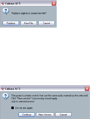
123
Audio processing and functions
Freeze Edits
The Freeze Edits function on the Audio menu allows you
to make all processing and applied effects permanent for
a clip:
1. Select the clip in the Pool or one of its events in the
Project window.
2. Select “Freeze Edits…” from the Audio menu.
•If there is only one edit version of the clip (no other clips
refer to the same audio file), the following dialog will appear:
If you select “Replace”, all edits will be applied to the orig-
inal audio file (the one listed in the clip’s Path column in
the Pool). If you select “New File”, the Freeze Edits opera-
tion will create a new file in the Audio folder within the
project folder (leaving the original audio file unaffected).
•If the selected clip (or the clip played by the selected
event) has several edit versions (i.e. there are other clips
referring to the same audio file), the following alert will
appear:
As you can see, you do not have the option to Replace the
original audio file in this case. This is because that audio
file is used by other clips. Select “New File” to have a new
file created in the Audio folder within the project folder.
12
The Sample Editor
125
The Sample Editor
Background
The Sample Editor allows you to view and manipulate audio
by cutting and pasting, removing or drawing audio data or
processing audio (see “Audio processing and functions”
on page 117). This editing can be called “non-destructive”:
The actual file (if created or imported from outside the
project) will remain untouched.
The Sample Editor also contains most of the AudioWarp
related functions, i.e. the realtime time stretching functions
in Cubase AI. These can be used to match the tempo of au-
dio loops to the project tempo (see “AudioWarp: Tempo
matching audio” on page 132).
Another special feature of the Sample Editor is hitpoint
detection. Hitpoints allow you to create “slices”, which are
useful, for example, if you want to change the tempo with-
out affecting the pitch (see “Working with hitpoints and
slices” on page 134).
Opening the Sample Editor
You open the Sample Editor by double-clicking an audio
event in the Project window or the Audio Part Editor, or by
double-clicking an audio clip in the Pool. You can have
more than one Sample Editor window open at the same
time.
•Note that double-clicking an audio part in the Project
window will open the Audio Part Editor, even if the part
only contains a single audio event.
This is described in a separate chapter, see “The Audio Part Editor” on
page 138.
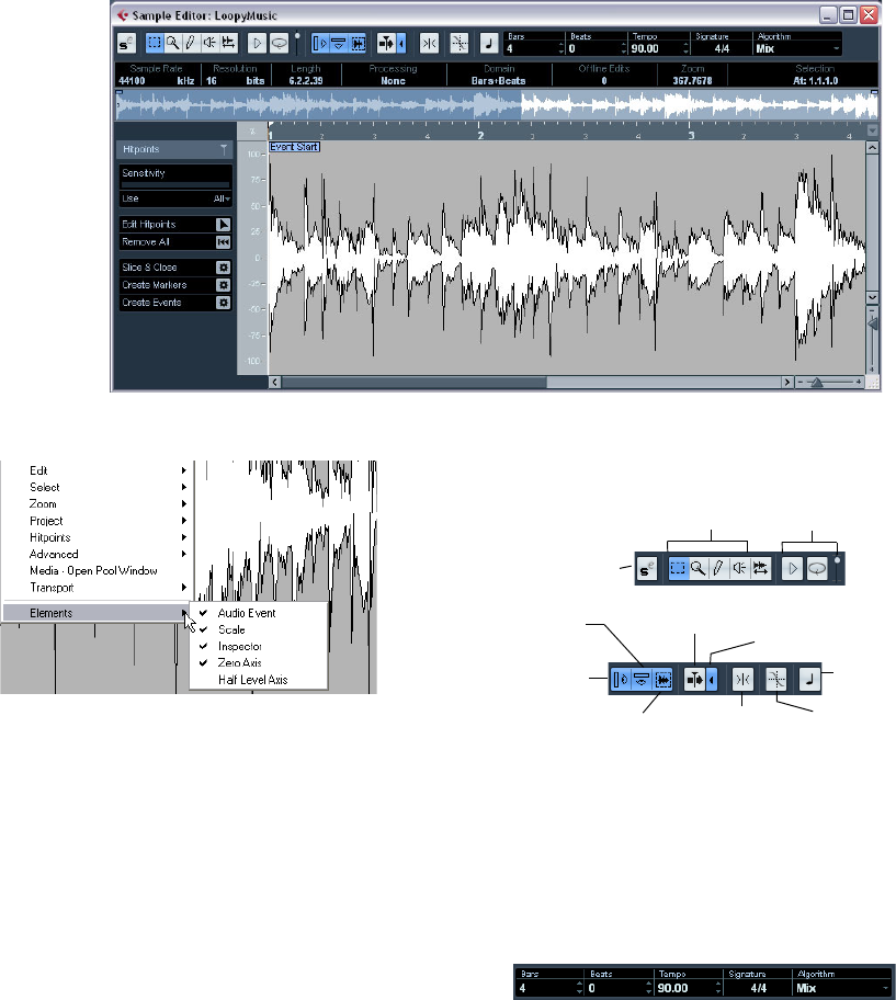
126
The Sample Editor
Window overview
The Elements menu
If you hold [Alt]/[Option] and right-click in the Sample Ed-
itor to bring up the context menu, you will find a submenu
called “Elements”. By activating or deactivating options on
this submenu, you specify what is shown in the editor win-
dow. Some of these options are also available as icons on
the toolbar.
ÖProvided that the “Popup Toolbox on Right Click” op-
tion in the Preferences dialog (Editing–Tools page) is ac-
tivated, a right-click holding a modifier key brings up the
context menu.
The toolbar
The toolbar contains the following tools:
To the right of the tools the estimated length of your audio
file is displayed in bars and beats (PPQ) together with the
estimated tempo and the time signature. If you want to use
Musical mode, you should always verify if the length in bars
corresponds to the audio file you imported. If necessary,
listen to your audio and enter the correct bar length. The
Algorithm pop-up allows you to select an algorithm for the
realtime time stretching.
•You can customize the toolbar by right-clicking it and
using the context menu to hide or show items.
The Sample
Editor tools Audition, Loop & Volume
controls
Solo Editor
Autoscroll
Show
Inspector
Snap on/offShow Audio Event
Show Info Suspend Autoscroll
when Editing
Snap to Zero Crossing
Musical Mode
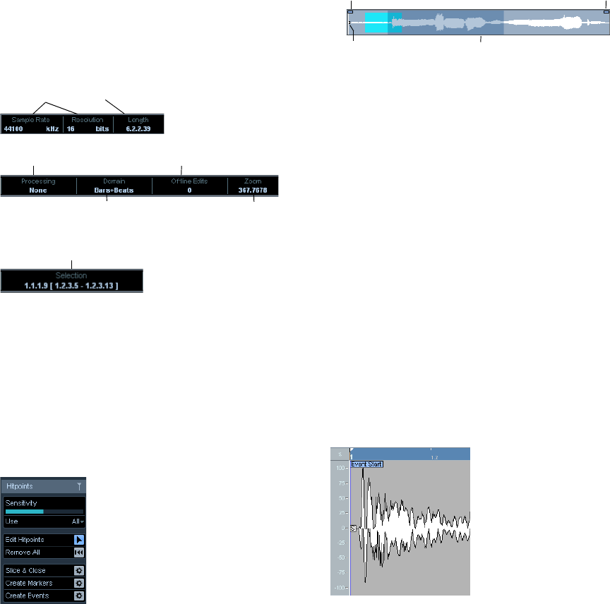
127
The Sample Editor
•Selecting “Setup…” from the context menu allows you
to rearrange sections on the toolbar, store toolbar presets,
etc., see “Using the Setup options” on page 262.
The info line
If you activate the Show Info button on the toolbar, the info
line will show information about the edited audio clip:
Initially, length and position values are displayed in the for-
mat specified in the Project Setup dialog. The info line can
be customized, see “The Setup dialogs” on page 262.
The Sample Editor Inspector
To the left in the Sample Editor, you will find the Sample Ed-
itor Inspector. It contains tools and functions for working in
the Sample Editor.
The Hitpoints tab
On this tab, the transients or hitpoints of the audio can be
marked and edited (see “Working with hitpoints and sli-
ces” on page 134). Hitpoints allow you to slice your audio,
and to create markers and events.
The thumbnail display
The thumbnail display provides an overview of the whole
clip. The section currently shown in the main waveform dis-
play of the Sample Editor is indicated by a blue rectangle in
the thumbnail, while the current selection range is shown in
light blue. If the “Show Audio Event” button is activated in
the toolbar, event start/end and snap point will also be
shown in the thumbnail display.
•You can move the blue rectangle in the thumbnail to
view other sections of the clip.
Click in the lower half of the rectangle and drag to the left or right to
move it.
•You can resize the blue rectangle (by dragging its left or
right edge) to zoom in or out, horizontally.
•You can define a new viewing area by clicking in the up-
per half of the overview and dragging a rectangle.
The ruler
The Sample Editor ruler is located between the thumbnail
and the waveform displays. The ruler is explained in detail
in the section “The ruler” on page 21.
The waveform display and the level scale
The waveform display shows the waveform image of the
edited audio clip according to the wave image style set in
the Preferences (Event Display–Audio page), see “Adjus-
ting how parts and events are shown” on page 25. To the
left of the waveform display a level scale can be shown, in-
dicating the amplitude of the audio.
Audio format and length
Selected display format
(for info line and ruler)
Number of edits made to the clip
Zoom factor
Realtime status
Current selection range
Event Start Event End
Snap Point Blue rectangle
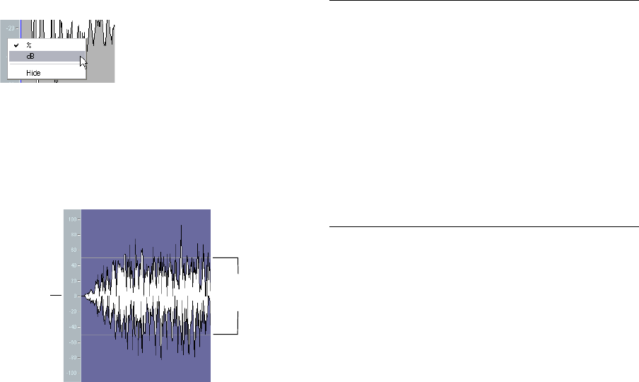
128
The Sample Editor
•When the level scale is shown, you can select whether
the level should be shown as a percentage or in dB.
This is done by right-clicking the level scale and selecting an option from
the context menu. This also allows you to hide the level scale.
•To display the level scale after hiding it, bring up the
Sample Editor context menu and activate Scale on the
Elements submenu.
•The Elements submenu also allows you to select
whether you want the zero axis and/or the half level axis in-
dicated in the waveform display.
General Operations
Zooming
Zooming in the Sample Editor is done according to the
standard zoom procedures, with the following special
notes:
•The vertical zoom slider changes the vertical scale rela-
tive to the height of the editor window, in a way similar to
the waveform zooming in the Project window (see “Zoom
and view options” on page 22).
The vertical zoom will also be affected if the Preference “Zoom Tool
Standard Mode: Horizontal Zooming only” (Editing–Tools page) is deac-
tivated and you drag a rectangle with the Zoom tool.
•The following options relevant to the Sample Editor are
available on the Zoom submenu of the Edit menu or the
context menu:
•You can also zoom by resizing the rectangle in the
thumbnail display.
See “The thumbnail display” on page 127.
•The current zoom setting is shown in the info line, as a
“samples per screen pixel” value.
•Note that you can zoom in horizontally to a scale of less
than one sample per pixel!
This is required for drawing with the Pencil tool (see “Drawing in the
Sample Editor” on page 131).
•If you have zoomed in to one sample per pixel or less,
the appearance of the samples depends on the option
“Interpolate Audio Images” in the Preferences (Event Dis-
play–Audio page).
If the option is deactivated, single sample values are drawn as “steps”. If
the option is activated, they are interpolated to a “curve” form.
Auditioning
While you can use the regular play commands to play
back audio when the Sample Editor is open, it is often
useful to listen to the edited material only.
ÖYou can adjust the auditioning level with the miniature
level fader on the toolbar.
Half
level
axis
Zero axis
Option Description
Zoom In Zooms in one step, centering on the position cursor.
Zoom Out Zooms out one step, centering on the position cursor.
Zoom Full Zooms out so that the whole clip is visible in the editor.
Zoom to
Selection Zooms in so that the current selection fills the editor
display.
Zoom to
Selection (Horiz.) Zooms in horizontally so that the current selection fills
the editor display.
Zoom to Event Zooms in so that the editor shows the section of the
clip corresponding to the edited audio event. This is
not available if you opened the Sample Editor from the
Pool (in which case the whole clip is opened for edit-
ing, not an event).
Zoom In/Out
Vertical This is the same as using the vertical zoom slider (see
above).
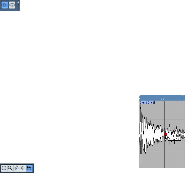
129
The Sample Editor
Using key commands
If you activate the “Playback Toggle triggers Local Preview”
option in the Preferences (Transport page), you can start/
stop auditioning by pressing [Space]. This is the same as
clicking the Audition icon on the toolbar.
Using the Audition icon
Clicking the Audition icon on the toolbar plays back the
edited audio, according to the following rules:
• If you have made a selection, this selection will be played back.
• If there is no selection, but the option “Show Event” is acti-
vated (see “Show Audio Event” on page 132), the section of
the clip corresponding to the event will be played back.
• If there is no selection, and “Show Event” is deactivated, play-
back will start at the cursor position (if the cursor is outside
the display, the whole clip will be played back).
• If the Audition Loop icon is activated, playback will continue
repeatedly until you deactivate the Audition Loop icon. Other-
wise, the section will be played back once.
Using the Speaker tool
If you click somewhere in the waveform display with the
Speaker (“Play”) tool and keep the mouse button pressed,
the clip will be played back from the position at which you
clicked. Playback will continue until you release the mouse
button.
Scrubbing
The Scrub tool allows you to locate positions in the audio
by playing back, forwards or backwards, at any speed:
1. Select the Scrub tool.
2. Click in the waveform display and keep the mouse
button pressed.
The project cursor is moved to the position at which you click.
3. Drag to the left or right.
The project cursor follows the mouse pointer and the audio is played
back. The speed and pitch of the playback depends on how fast you
move the pointer.
•You can adjust the response of the Scrub tool with the
Scrub Response (Speed) setting in the Preferences
(Transport–Scrub page).
You will also find a separate Scrub Volume setting on this page.
Adjusting the snap point
The snap point is a marker within an audio event (or clip,
see below). This is used as a reference position when you
are moving events with snap activated, so that the snap
point is “magnetic” to whatever snap positions you have
selected.
By default, the snap point is set at the beginning of the au-
dio event, but often it is useful to move the snap point to a
“relevant” position in the event, such as a downbeat, etc.
1. Activate the “Show Audio Event” option on the toolbar,
so that the event is displayed in the editor.
2. Scroll so that the event is visible, and locate the “S”
flag in the event.
If you haven’t adjusted this previously, it will be located at the beginning
of the event.
3. Click on the “S” flag and drag it to the desired position.
When you drag the snap point, a tooltip shows its current position (in the
format selected on the Sample Editor ruler).
•If the Scrub tool is selected when you move the snap
point, you will hear the audio while dragging (just like
when scrubbing).
This makes it easier to find the correct position.
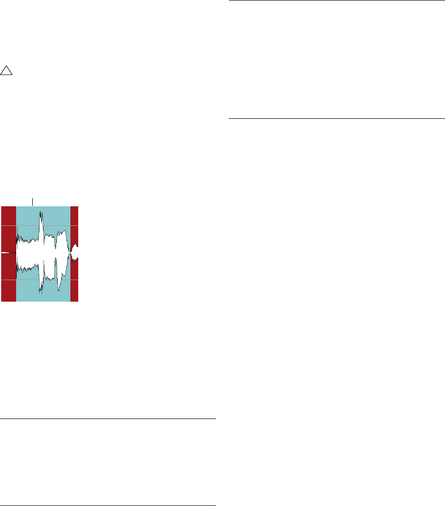
130
The Sample Editor
•It is also possible to define a snap point for a clip (for
which there is no event yet).
To open a clip in the Sample Editor, double-click it in the Pool. After hav-
ing set the snap point using the procedure described above, you can in-
sert the clip into the project from the Pool or the Sample Editor, taking
the snap point position into account.
Making selections
To select an audio section in the Sample Editor, you click
and drag with the Range Selection tool.
•If Snap to Zero Crossing is activated on the toolbar, the
start and end of the selection will always be at zero cross-
ings (see “Snap” on page 132).
•You can resize the selection by dragging its left and
right edge or by [Shift]-clicking.
Using the Select menu
In the Select submenu of the Edit menu you can find the
following options:
Editing selection ranges
Selections in the Sample Editor can be processed in sev-
eral ways. Please note the following:
•If you attempt to edit an event that is a shared copy (i.e.
the event refers to a clip that is used by other events in the
project), you are asked whether you want to create a new
version of the clip.
Select “New Version” if you want the editing to affect the selected event
only. Select “Continue” if you want the editing to affect all shared copies.
Note: If you activate the option “Do not show this message again” in the
dialog, any further editing you do will conform to the selected method
(“Continue” or “New Version”). You can change this setting at any time
with the “On Processing Shared Clips” pop-up menu in the Preferences
(Editing–Audio page).
Cut, Copy and Paste
The Cut, Copy and Paste commands (on the Edit menu in
the Sample Editor context menu or in the main Edit menu)
work according to the following rules:
•Selecting Copy copies the selection to the clipboard.
•Selecting Cut removes the selection from the clip and
moves it to the clipboard.
The section to the right of the selection is moved to the left to fill the gap.
!
Events and clips can have different snap points. If
you open a clip from the Pool you can edit the clip
snap point. If you open a clip from within the project
window, you can edit the event snap point. The clip
snap serves as a template for the event snap point
and does not affect snapping.
Function Description
All Selects the whole clip.
None Selects no audio (the selection length is set to “0”).
In Loop Selects all audio between the left and right locator.
Select Event Selects the audio that is included in the edited event
only. This is not available if you opened the Sample Edi-
tor from the Pool (in which case the whole clip is
opened for editing, not an event).
A selected range
From Start
to Cursor Selects all audio between the clip start and the project
cursor.
From Cursor
to End Selects all audio between the project cursor and the
end of the clip. For this to work, the project cursor must
be within the clip boundaries.
Left Selection
Side to Cursor Moves the left side of the current selection range to the
project cursor position. For this to work, the cursor must
be within the clip boundaries.
Right Selection
Side to Cursor Moves the right side of the current selection range to
the project cursor position (or the end of the clip, if the
cursor is to the right of the clip).
Function Description
131
The Sample Editor
•Selecting Paste copies the data on the clipboard into
the clip.
If there is a selection in the editor, this will be replaced by the pasted
data. If there is no selection, the pasted data will be inserted starting at
the selection line. The section to the right of the line will be moved to
make room for the pasted material.
The pasted data will be inserted at the selection line.
Delete
Selecting Delete (on the Edit menu in the Sample Editor
context menu or in the main Edit menu or by pressing
[Backspace]) removes the selection from the clip. The
section to the right of the selection is moved to the left to
fill out the gap.
Insert Silence
Selecting “Insert Silence” (in the Range submenu of the
main Edit menu) will insert a silent section with the same
length as the current selection, at the selection start.
•The selection will not be replaced, but moved to the
right to make room.
If you want to replace the selection, use the “Silence” function instead
(see “Silence” on page 121).
Processing
The Processing features (in the Process submenu on the
Audio menu) can be applied to selections in the Sample
Editor. See the chapter “Audio processing and functions”
on page 117.
Creating a new event from the selection using drag&drop
You can create a new event that plays only the selected
range, using the following method:
1. Make a selection range.
2. Press [Ctrl]/[Command] and drag the selection range
to the desired audio track in the Project window.
Creating a new clip or audio file from the selection
You can extract a selection from an event and either cre-
ate a new clip or a new audio file, in the following way:
1. Make a selection range.
2. Holding [Alt]/[Option], right-click to open the context
menu and select “Bounce Selection” from the Audio sub-
menu.
Provided that the “Popup Toolbox on Right Click” option in the Prefer-
ences dialog (Editing–Tools page) is activated, a right-click holding a
modifier key brings up the context menu.
A new clip is created and added to the Pool, and another
Sample Editor window opens with the new clip. This clip
refers to the same audio file as the original clip, but only
contains the audio corresponding to the selection range.
Drawing in the Sample Editor
It is possible to edit the audio clip at sample level by draw-
ing with the Pencil tool. This can be useful if you need to
manually edit out a spike or click, etc.
1. Zoom in to a zoom value lower than 1.
This means that there is more than one screen pixel per sample.
2. Select the Pencil tool.
3. Click and draw at the desired position in the waveform
display.
When you release the mouse button, the edited section is automatically
selected.
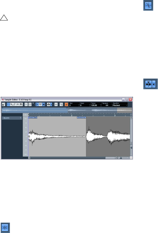
132
The Sample Editor
Options and settings
Show Audio Event
When the Show Audio Event button is activated on the
toolbar (or the option “Audio Event” is activated on the
Elements submenu of the context menu), the section cor-
responding to the edited event is highlighted in the wave-
form and thumbnail displays. The sections of the audio
clip not belonging to the event are shown with a dark gray
background.
•In this mode, you can adjust the start and end of the
event in the clip by dragging the event handles in the
waveform display.
When you move the pointer over the event handles (no matter what tool
may be selected), it takes on the shape of an arrow, to indicate that you
can click and drag.
Snap
Snap activated.
The Snap function helps you to find exact positions when
editing in the Sample Editor. It does this by restricting hor-
izontal movement and positioning to certain grid positions.
You turn Snap on or off by clicking the Snap button in the
Sample Editor toolbar.
ÖThe Sample Editor Snap function is independent of
the Snap setting in the Project window toolbar or other
editors. It has no effect outside the Sample Editor.
Snap to Zero Crossing
Snap to Zero Crossing activated.
This setting is linked to the Snap to Zero Crossing setting
in the Project window, see the section “Snap to Zero
Crossing” on page 41.
ÖIf hitpoints have been calculated, these will also be
taken into account when snapping to zero crossings.
Autoscroll
Autoscroll and Suspend Autoscroll when Editing activated.
When this option is activated on the Sample Editor tool-
bar, the waveform display will scroll during playback,
keeping the project cursor visible in the editor.
This setting is independent of the Autoscroll setting in the
Project window toolbar or other editors. For more infor-
mation on this function, see the section “Autoscroll” on
page 41.
AudioWarp: Tempo matching audio
In Cubase AI you can use the Musical mode to tempo-
match audio loops to the project tempo. It allows you to
lock audio clips to the project tempo by using realtime
time stretching. This is very useful if you want to use loops
in your project and do not want to worry too much about
timing.
When Musical mode is activated, audio events will adapt
to any tempo changes in Cubase AI, just like MIDI events.
However, using this function should not be confused with
quantizing: the timing, i.e. the rhythmic feeling will be
maintained.
It is also possible to activate/deactivate Musical mode from
within the Pool by clicking the corresponding checkbox in
the Musical Mode column.
!
This is only available if you opened the Sample Editor
by double-clicking an audio event in the Project win-
dow or the Audio Part Editor and not, if you opened
the audio event from within the Pool.
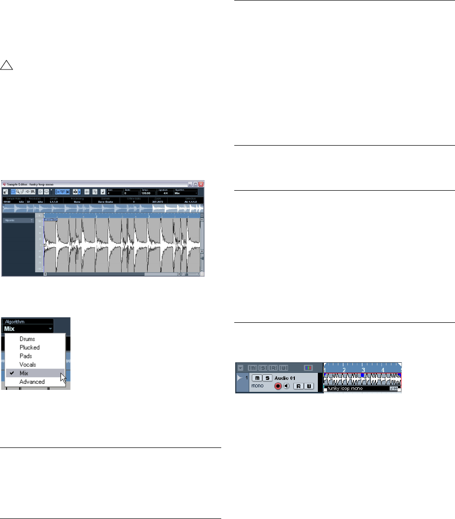
133
The Sample Editor
When you have correctly set a tempo or length for an au-
dio clip, this information is saved with the project. This al-
lows you to import files into the project with Musical mode
already activated. The tempo (if set) is also saved when
exporting files.
Proceed as follows to tempo match an audio loop to the
project tempo:
1. Import your loop into the project and double-click it to
open it in the Sample Editor.
2. From the Algorithm pop-up in the toolbar, select the
algorithm to be applied on realtime playback.
In this pop-up you can find various options that govern the
audio quality of the realtime time stretching. There are pre-
sets for common types of audio material and an Advanced
option which allows you to manually set warp parameters:
If you select the Advanced menu item, a dialog opens
where you can manually adjust the three parameters that
govern the sound quality of the time stretching:
3. Activate the Musical Mode button on the toolbar.
Your loop will automatically be adapted to the project tempo.
As you can see, it is very easy to adapt audio loops to the
project tempo.
!
Cubase AI supports ACID® loops. These loops are
standard audio files but with embedded tempo/length
information. When ACID® files are imported into Cu-
base AI, Musical mode is automatically activated and
the loops will adapt to the tempo set in the project.
Option Description
Drums This mode is best for percussive sounds, because it will not
change the timing of your audio. Using this option for pitched
audio will lead to noticeable artifacts. In this case, you can try
the Mix mode.
Plucked This should be used for audio with transients and a relatively
stable spectral sound character (e.g. plucked instruments).
Pads Use this mode for pitched audio with slower rhythm and a sta-
ble spectral sound character. This will minimize sound arti-
facts, but the rhythmic accuracy will not be preserved.
Vocals This mode was optimized for slower signals with transients
and a prominent tonal character (e.g. vocals).
Mix This mode will preserve the rhythm and minimize the artifacts
for pitched material which does not meet the above criteria
(i.e. with a less homogenous sound character).
This will be selected by default for audio that is not catego-
rized.
Advanced This allows for a manual tweaking of the time stretching pa-
rameters. The settings that are shown when you open the dia-
log are those of the last used preset. The Advanced settings
are described in more detail below this table.
Parameter Description
Grainsize The realtime time stretching algorithm splits the audio into
small pieces called “grains”. This parameter determines the
size of the grains. For material with many transients you
should use low Grainsize values for best results.
Overlap Overlap is the percentage of the whole grain that will over-
lap with other grains. Use higher values for material with a
stable sound character.
Variance Variance is also a percentage of the whole length of the
grains and sets a variation in positioning so that the overlap-
ping area will sound smooth. A Variance setting of 0 will
produce a sound akin to time stretching used in early sam-
plers, whereas higher settings will produce more (rhythmic)
“smearing” effects but less audio artifacts.
Option Description

134
The Sample Editor
Working with hitpoints and slices
Hitpoint detection is a special feature of the Sample Edi-
tor. It detects attack transients in an audio file and then
adds a type of marker, i.e. a “hitpoint”, at each transient.
These hitpoints allow you to create “slices”, where each
slice ideally represents each individual sound or “beat” in
a loop (drum or other rhythmic loops work best with this
feature). When you have successfully sliced the audio file,
you can do a number of useful things with it:
• Change the tempo without affecting the pitch.
• Replace individual sounds in a drum loop.
• Edit the actual playing in the drum loop without affecting the
basic feel.
• Extract sounds from loops.
You can further edit these slices in the Audio Part Editor.
For example you can:
• Remove or mute slices.
• Change the loop by reordering or replacing slices.
• Apply processing to individual slices.
• Create new files from individual slices using the “Bounce Se-
lection” function on the Audio menu.
• Edit slice envelopes.
ÖThe term “loop” is used throughout this section. Loop
in this context usually means an audio file with a musical
time base, i.e. the length of the loop represents a certain
number of bars and beats at a certain tempo. Playing the
loop back at the right tempo in a cycle set to the correct
length will produce a continuous loop without gaps.
Using hitpoints
The main functionality of using hitpoints to slice up a loop is
to make a loop fit the tempo of a song, or alternatively to
create a situation that allows the song tempo to be changed
while retaining the timing of a rhythmic audio loop, just like
when using MIDI files.
Which audio files can be used?
Here are some guidelines as to what type of audio files are
suited for slicing using hitpoints:
•Each individual sound in the loop should have a notice-
able attack.
Slow attacks, legato playing, etc. may not produce the desired result.
•Poorly recorded audio might be difficult to slice correctly.
In these cases, try to normalize the files or to remove DC Offset.
•There may be problems with sounds drowned in smear-
ing effects, like short delays.
Calculating hitpoints and slicing a loop
Before proceeding, find a suitable loop using the criteria
above. Proceed as follows:
1. Open the event or clip for editing in the Sample Editor.
You can do this by double-clicking an event on an audio track in the
Project window or a clip in the Pool. In this example, we assume you
work with an event on a track.
2. Open the Hitpoints tab in the Sample Editor Inspector
and select an option from the Use pop-up.
The Use pop-up menu on the Hitpoints tab affects which hitpoints are
shown and is a useful tool for removing unwanted hitpoints.
It contains the following options:
3. Move the Sensitivity slider to the right to add hitpoints
or to the left to remove unwanted hitpoints until one indi-
vidual sound is played between each hitpoint.
If your main reason for slicing the loop is to change the tempo, you gener-
ally need as many slices as you can get, but never more than one per indi-
vidual “hit” in the loop.
In the next step, the loop will be adapted to the project
tempo set in Cubase AI.
!
When a selection range is defined, hitpoints will only
be detected within this range.
!
Hitpoints will only be displayed in the waveform if the
Hitpoints tab is open.
Option Description
All All hitpoints are shown (taking the Sensitivity slider into ac-
count).
1/4, 1/8,
1/16, 1/32 Only hitpoints that are close to the selected note value posi-
tions within the loop are shown (e.g. close to exact sixteenth
note positions). Again, the Sensitivity slider is taken into ac-
count.
Metric Bias This is like the “All” mode, but all hitpoints that are close to
even meter divisions (1/4, 1/8, 1/16, etc.) get a “sensitivity
boost” – they are visible at lower sensitivity settings. This is
useful if you are working with dense or cluttered material with
a lot of hitpoints, but you know that the material is based on a
strict meter. By selecting Metric Bias it will be easier to find
the hitpoints close to the meter position (although most other
hitpoints are also available, at higher sensitivity settings).
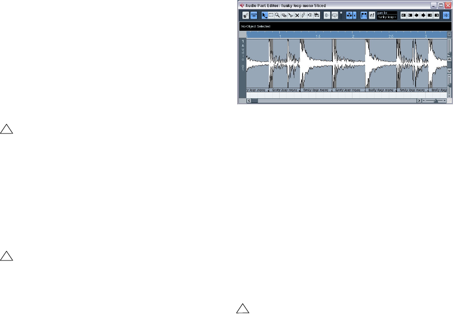
135
The Sample Editor
4. Verify the Tempo and Bars values in the toolbar.
5. On the Hitpoints tab, click on the Slice & Close button
or select “Create Audio Slices from Hitpoints” from the
Hitpoints submenu on the Audio menu to create audio
slices from the hitpoints.
The following happens:
•The Sample Editor closes.
•The audio event is “sliced” so that the sections between
the hitpoints become separate events, all referring to the
same original file.
•The audio event is replaced by an audio part, containing
the slices (double-click the part to view the slices in the Au-
dio Part Editor). If you edited a clip from the Pool, you need
to drag it to an audio track to get a part with the slices.
•The loop is automatically adapted to the project tempo.
This takes the loop length you specified into account: e.g., if
the loop was one bar long, the part is resized to fit exactly
one bar in the Cubase AI tempo, and the slices are moved
accordingly, keeping their relative positions within the part.
•In the Pool, the sliced clip is shown with a different icon.
Dragging the sliced clip from the Pool to an audio track will create an audio
part with the slices adapted to the project tempo, just as above.
6. Activate cycle playback on the Transport panel.
The loop should now play back seamlessly at the tempo set in the project!
•If the project tempo is lower than the original tempo of
the loop, there may be audible gaps between each slice
event in the part.
This can be remedied by using the Close Gaps function on the Advanced
submenu of the Audio menu, see “Close Gaps” on page 136. You should
also consider activating auto fades for the corresponding audio track –
fade-outs set to about 10ms will help eliminate any clicks between the
slices when you play back the part. See “Fades, crossfades and envelo-
pes” on page 62 for details.
•If the project tempo is higher than the loop’s original
tempo, you may want to activate auto crossfades for the
track.
You can use the Close Gaps functions in this case as well, see “Close
Gaps” on page 136.
The slices in the Audio Part Editor. Here, the project tempo was higher
than the loop’s original tempo – the slice events overlap slightly.
Setting hitpoints manually
If you cannot get the desired result by adjusting the sensi-
tivity, try to set and edit hitpoints manually.
1. Zoom in on the waveform at the point where you wish
to add a hitpoint.
2. Select the Edit Hitpoints tool to audition the area and
make sure that the start of the sound is in view.
•Activate Snap to Zero Crossing on the Sample Editor
toolbar.
By finding zero crossings in the waveform (positions where the amplitude
is close to zero), manually added slices won’t introduce any clicks or pops.
All hitpoints calculated by the program are automatically placed at zero
crossings.
3. Press [Alt]/[Option] so that the mouse pointer changes
to a pencil tool and click just before the start of the sound.
A new hitpoint appears. Manually added hitpoints are locked by default.
•If you notice that a hitpoint was either placed too far
away from the start of the sound or too far into the sound,
you can move it by clicking on the hitpoint handle and
dragging it to the new position.
!
When you create slices, all events containing the ed-
ited clip will also be replaced.
!
Only when the audio tempo has been defined and
the audio grid matches the project tempo, your slices
will be straight (quantized).
!
“Snap to Zero Crossing” may alter the timing. In
some cases it might therefore be better to deactivate
it. However, if you create slices afterwards, auto
fades will be necessary.
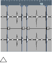
136
The Sample Editor
4. Audition the slices by pointing and clicking in any slice
area.
The pointer changes to a speaker icon and the corresponding slice will be
played back from the beginning to the end.
•If you hear a single sound split into two slice you can
disable an individual slice by pressing [Alt]/[Option] (the
pointer turns into a cross) and clicking on the correspond-
ing hitpoint handle.
The hitpoint handle gets smaller and its line disappears to indicate that it
is disabled. To reactivate a disabled hitpoint, [Alt]/[Option]-click on the
hitpoint handle again.
•If you hear “double hits” (e.g. a snare hit being followed
by a hi-hat hit within the same slice) you can add further hit-
points manually, or you can move the Sensitivity slider to the
right until the hitpoint appears, lock this hitpoint by pointing
on the handle until it becomes green and click on it.
Locked hitpoints are displayed in a darker color. After locking the hitpoint
you can drag the sensitivity slider to the original setting and the locked
hitpoint will remain shown. You can unlock a locked hitpoint by clicking
on its handle.
•If you want to delete a hitpoint, simply drag it out of the
Sample Editor window.
Hitpoints that you have created manually can also be deleted by clicking
their handle.
Match-quantizing audio
Hitpoints can have individual Q-points. These are mainly
used for audio quantizing. Their function is to define the
point to which the quantizing will apply. Sometimes a slice
might have a slow attack, and a peak further into the slice
which you wish to use as the Q-point. When you apply
quantize, the Q-point will define where the warp tab will be
added. This also defines the point which will be stretched
to a grid position when quantizing.
•To activate Q-points, open the Preferences (Editing–
Audio page) and activate the option “Hitpoints have
Q-Points”.
Next time you use the Calculate Hitpoints function, the hitpoints will have
Q-points.
•To offset the position of a Q-point in relation to the hit-
point, simply click on the “Q” icon and drag it to the right
to the desired position.
Other hitpoint functions
On the Hitpoints tab of the Sample Editor Inspector and
on the various submenus of the Audio menu, you will also
find the following functions:
Create Markers
If an audio event contains calculated hitpoints, you can
click on the Create Markers button in the Hitpoints tab to
add a marker for each hitpoint (see “Marker tracks” on
page 19). This can be useful to snap to hitpoints, e.g. for
locating hitpoints.
Create Events
When you wish to create separate events according to the
hitpoints for a file, you can click on the Create Events but-
ton in the Hitpoints tab. This means that you do not have to
make the same considerations as when slicing for tempo
changes. You can use any method you like to set hitpoints.
•The slices created will appear in the Project window as
separate events.
Close Gaps
This function from the Advanced submenu on the Audio
menu is useful if you sliced a loop for tempo changes.
Lowering the tempo below the loop’s original tempo will
create gaps between the slices. The lower the tempo is in
relation to the original tempo, the wider the gaps will be.
Close Gaps can be used to remedy this.
Proceed as follows:
1. Set the desired tempo.
2. Select the part containing the slices in the Project win-
dow.
!
Sounds with a slow attack have their rhythmic center
at some point before the peak.
137
The Sample Editor
3. Select “Close Gaps” from the Advanced submenu on
the Audio menu.
Time stretch is applied to each slice to close the gaps. Depending on the
length of the part and the algorithm set in the Preferences (Editing–Au-
dio page), this can take a little while.
4. The waveform is redrawn and the gaps are closed!
•Note that this feature creates new clips in the Pool, one
for each slice.
•Close Gaps can also be used when the project tempo
is higher than the original loop tempo.
This will use the time stretch function to compress the slices to fit.
•If you decide to change the tempo again after using the
Close Gaps function, you should undo the Close Gaps op-
eration or start over again, using the original unstretched
file.
•You can also use this function on individual events (in
the Audio Part Editor or Project window).
The events don’t have to be slices – you can use Close Gaps simply to
stretch an audio event to the start position of the next event.
ÖThere are some restrictions concerning the highest
and lowest possible note pitch. You cannot choose note
pitches above C5 and below E0.
13
The Audio Part Editor
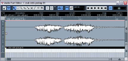
139
The Audio Part Editor
Background
The Audio Part Editor allows you to view and edit the events
inside audio parts. Essentially, this is the same type of edit-
ing that you do in the Project window, which means that
this chapter contains a lot of references to the chapter “The
Project window” on page 14.
Audio parts are created in the Project window in one of
the following ways:
•By selecting one or several audio events on the same
track, and selecting “Events to Part” from the Audio menu.
•By gluing together two or more audio events on the
same track with the Glue Tube tool.
•By drawing an empty part with the Pencil tool.
•By double-clicking between the left and right locator on
an audio track.
With the last two methods, an empty part is created. You can then add
events to the part by pasting, or by using drag and drop from the Pool.
Opening the Audio Part Editor
You open the Audio Part Editor by selecting one or more
audio part(s) in the Project window and double-clicking
on any one of them (or using the Edit-Open key command,
by default [Ctrl]/[Command]-[E]). The Audio Part Editor
can display several parts at once, and you can also have
more than one Audio Part Editor open at the same time.
ÖDouble-clicking on an audio event in the Project win-
dow will open the Sample Editor (see “Opening the
Sample Editor” on page 125).
Window overview
The toolbar
The tools, settings and icons on the toolbar have the same
functionality as in the Project window, with the following
differences:
• A Solo button (see “Auditioning” on page 141).
• Separate tools for auditioning (Speaker) and scrubbing (see
“Scrubbing” on page 141).
• No Line, Glue Tube or Color tools.
• Play and Loop icons and an Audition Volume control (see
“Auditioning” on page 141).
• Part List controls for handling several parts: activating parts
for editing, restricting editing to active parts only and showing
part borders (see “Handling several parts” on page 141).
ÖYou can customize the toolbar by hiding or reordering
its items.
See “Using the Setup options” on page 262.
The ruler and info line
These have the same functionality and appearance as
their counterparts in the Project window.
•You can select a separate display format for the Audio
Part Editor ruler by clicking on the arrow button on the right
and selecting an option from the pop-up menu.
For a list of the available formats, see “The ruler” on page 21.
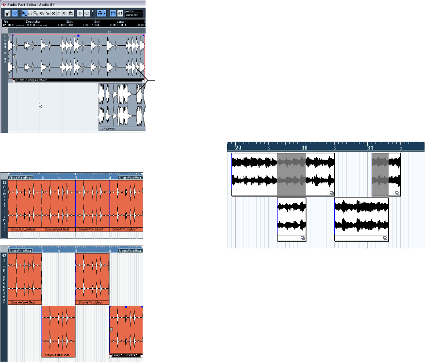
140
The Audio Part Editor
About lanes
If you make the editor window larger, this will reveal addi-
tional space below the edited events. This is because an
audio part is divided vertically in lanes.
Lanes can make it easier to work with several audio events
in a part:
In the upper figure it is unnecessarily hard to discern, se-
lect and edit the separate events. In the lower figure, some
of the events have been moved to another lower lane,
making selection and editing much easier.
•To move an event to another lane without accidentally
moving it horizontally, press [Ctrl]/[Command] and drag it
up or down.
This is the default modifier key for this – you can adjust this in the Prefe-
rences if you like.
Overlapping events
Only one event per track can be played back at the same
time! This means that if you have overlapping events (on
the same lane or different lanes) these will cut each other
off, according to the following rules:
•For events on the same lane, the ones that are on top
(visible) will be played.
To move overlapping events to the front or back, use the Move to Front
and Move to Back functions on the Edit menu.
•For events on different lanes, the event on the lowest
lane gets playback priority.
The overlapping sections of the upper event will not be played since the
event on the lower lane has playback priority!
Imagine the following situation: You have two overlapping
audio events, with the top event audible during playback.
What happens when you mute the audible event?
•By default, you will not hear the overlapped event when
muting an event that has playback priority over another
event.
This default behavior ensures that you do not suddenly hear audio events
that previously were not part of your mix.
•In the Preferences dialog (Editing–Audio page) you will
find the option “Treat Muted Audio Events like Deleted”.
When you activate this option, any events overlapped by a
muted event will become audible.
Lanes
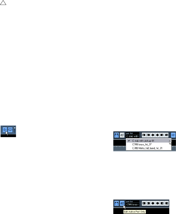
141
The Audio Part Editor
Operations
•Note that if a part is a shared copy (i.e. you have previ-
ously copied the part by [Alt]/[Option]-[Shift] and drag-
ging), any editing you perform will affect all shared copies
of this part.
To indicate that it is a shared copy, its name is displayed in italics and a
symbol is displayed in the lower right corner of the part in the Project
window.
Auditioning
There are three ways to listen to the events in the Audio
Part Editor:
By using the Speaker tool
If you click somewhere in the editor’s event display with the
Speaker tool and keep the mouse button pressed, the part
will be played back from the position where you clicked.
Playback will continue until you release the mouse button.
By using the Audition icon
The Audition and Audition Loop icons.
Clicking the Audition icon on the toolbar plays back the
edited audio, according to the following rules:
• If you have selected events in the part, only the section bet-
ween the first and last selected event will be played back.
• If you have made a range selection, only this section will be
played back.
• If there is no selection, the whole part will be played back. If
the project cursor is within the part, playback starts from the
current cursor position. If the cursor is outside the part, play-
back starts from the beginning of the part.
• If the Audition Loop icon is activated, playback will continue
until you deactivate the Audition icon. Otherwise, the section
will be played back once.
•When auditioning with the Speaker tool or Audition
icon, audio will be routed directly to the Main Mix (the de-
fault output bus).
By using regular playback
You can of course use the regular playback controls while
in the Audio Part Editor. Furthermore, if you activate the
Solo Editor button on the toolbar, only the events in the
edited part will be played back.
Scrubbing
In the Audio Part Editor, the Scrub tool has a separate icon
on the toolbar. Apart from that, scrubbing works exactly as
in the Project window (see “Scrubbing” on page 28).
Handling several parts
When you open the Audio Part Editor with several parts se-
lected – all on the same track or on different tracks – they
might not all “fit” in the editor window, which can make it
hard to get an overview of the different parts when editing.
Therefore, the toolbar features a few functions to make
working with multiple parts easier and more comprehen-
sive:
•The Part List menu lists all parts that were selected
when you opened the editor, and lets you select which
part should be active for editing.
When you select a part from the list, it is automatically made active and
centered in the display.
ÖNote that it is also possible to activate a part by click-
ing on it with the Arrow tool.
•The button “Edit Active Part Only” lets you restrict edit-
ing operations to the active part only.
If you for example select “All” from the Select submenu on the Edit menu
with this option activated, all events in the active part will be selected but
not the events in other parts.
“Edit Active Part Only” activated on the toolbar.
•You can zoom in on an active part so that it fills the
screen by selecting “Zoom to Event” from the Zoom sub-
menu on the Edit menu.
!
Zooming, selecting and editing in the Audio Part Ed-
itor are done just as in the Project window (see
“Operations” on page 21).
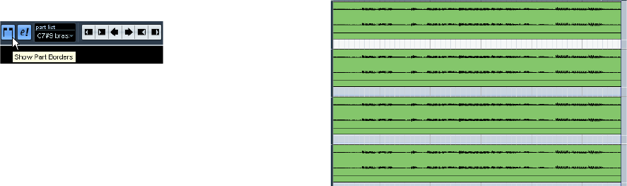
142
The Audio Part Editor
•The button “Show Part Borders” can be used if you
want to see clearly defined borders for the active part.
When this is activated, all parts except the active one are grayed out,
making the borders easily discernible. There are also two “markers” in
the ruler with the name of the active part, marking its beginning and end.
These can be moved freely to change the part borders.
“Show Part Borders” activated on the toolbar.
•It is possible to cycle between parts, making them ac-
tive using key commands.
In the Key Commands dialog – Edit category, there are two functions:
“Activate Next Part” and “Activate Previous Part”. If you assign key com-
mands to these, you can use them to cycle between parts. See “Setting
up key commands” on page 269 for instructions on how to set up key
commands.
Common methods
Assembling a “perfect take”
When you record audio in Cycle mode, an event is cre-
ated for each recorded lap (see “Recording audio in cycle
mode” on page 54). These events are named “Take X”,
where “X” is the number of the take. You can create a per-
fect take by putting together sections of the different takes
in the Audio Part Editor.
ÖThe procedure below will not work if you recorded
with “Keep Last” mode selected on the Transport panel.
In that case, only the last take will be kept on the track.
First, you have to create an audio part from the takes.
Creating an audio part from events
1. In the Project window, use the Object Selection tool to
draw a rectangle around the recorded events.
This is necessary, since clicking on the event may just select the event on
top (the last take). If in doubt, check the info line – the info text should be
yellow.
2. Pull down the Audio menu and select “Events to Part”.
The events are converted to an audio part.
Assembling a take
1. Double-click the part to open the Audio Part Editor.
Now, the different takes will be placed on different lanes, with the last
take at the bottom.
2. Use the tools to cut out pieces of the takes and as-
semble the final result.
This can include splitting with the Scissors tool, resizing events with the
Arrow tool or deleting with the Erase tool.
•Remember that the events on the lowest lane have play-
back priority.
Use the Audition icon to audition the result.
3. Close the Audio Part Editor.
You have now assembled a “perfect take”!
Options and Settings
The following options and settings are available in the
Audio Part Editor:
•Snap
You can specify an independent Snap mode (and snap value for the Grid
mode) in the editor. The functionality is exactly the same as in the Project
window.
•Autoscroll
When Autoscroll is activated on the toolbar, the window will scroll during
playback, keeping the project cursor visible in the editor. This setting can
be activated or deactivated individually for each window.
•Snap to Zero Crossing
When this option is activated, all audio edits are done at zero crossings
(positions in the audio where the amplitude is zero). This helps you avoid
pops and clicks which might otherwise be caused by sudden amplitude
changes.
14
The Pool
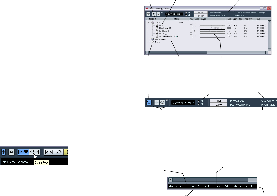
144
The Pool
Background
Every time you record on an audio track, a file is created
on your hard disk. A reference to this file – a clip – is also
added to the Pool. Two general rules apply to the Pool:
•All audio and video clips that belong to a project are
listed in the Pool.
•There is a separate Pool for every project.
The way the Pool displays folders and their contents is
similar to the way the Mac OS X Finder and the Windows
Explorer display folders and lists of files.
In the Pool you can, among other things, perform the fol-
lowing operations:
Operations that affect files on disk
• Importing clips (audio files can automatically be copied and/or
converted)
• Converting file formats
• Renaming clips (this will also rename the referenced files on
disk)
• Deleting clips
• Preparing file archives for backup
• Minimizing files
Operations that only affect clips
• Copying clips
• Auditioning clips
• Organizing clips
• Applying audio processing to clips
Opening the Pool
You can open the Pool in any of the following ways:
•By clicking the Open Pool button on the Project window
toolbar.
•By selecting “Pool” on the Project menu or “Open Pool
Window” on the Media menu.
•By using a key command (by default [Ctrl]/[Command]-
[P] – note that using this key command a second time will
close the Pool again).
The content of the Pool is divided into three main folders:
•The Audio folder
This contains all audio clips currently in the project.
•The Video folder
This contains all video clips currently in the project.
•The Trash folder
Unused clips can be moved into the Trash folder for later permanent re-
moval from the hard disk.
These folders cannot be renamed or deleted from the Pool,
but any number of subfolders can be added (see “Organi-
zing clips and folders” on page 152).
Window overview
Toolbar overview
The info line
Click the “Show Info” button on the toolbar to show or
hide the info line at the bottom of the Pool window. It
shows the following information:
Audio folder
Trash folder Video folder
Audio clip name
Waveform image
Toolbar
Open/Close all
folders
View/Attributes
pop-up
Show Info
button Project Folder
path
Pool Record
Folder path
Audition, Audition Loop, and
Volume controls Import and Search
buttons
Number of audio files in
the Pool
Number of files in the Pool that are not in
the project folder (e.g. video files)
Total size of all audio files in
the Pool
Number of audio files
in use
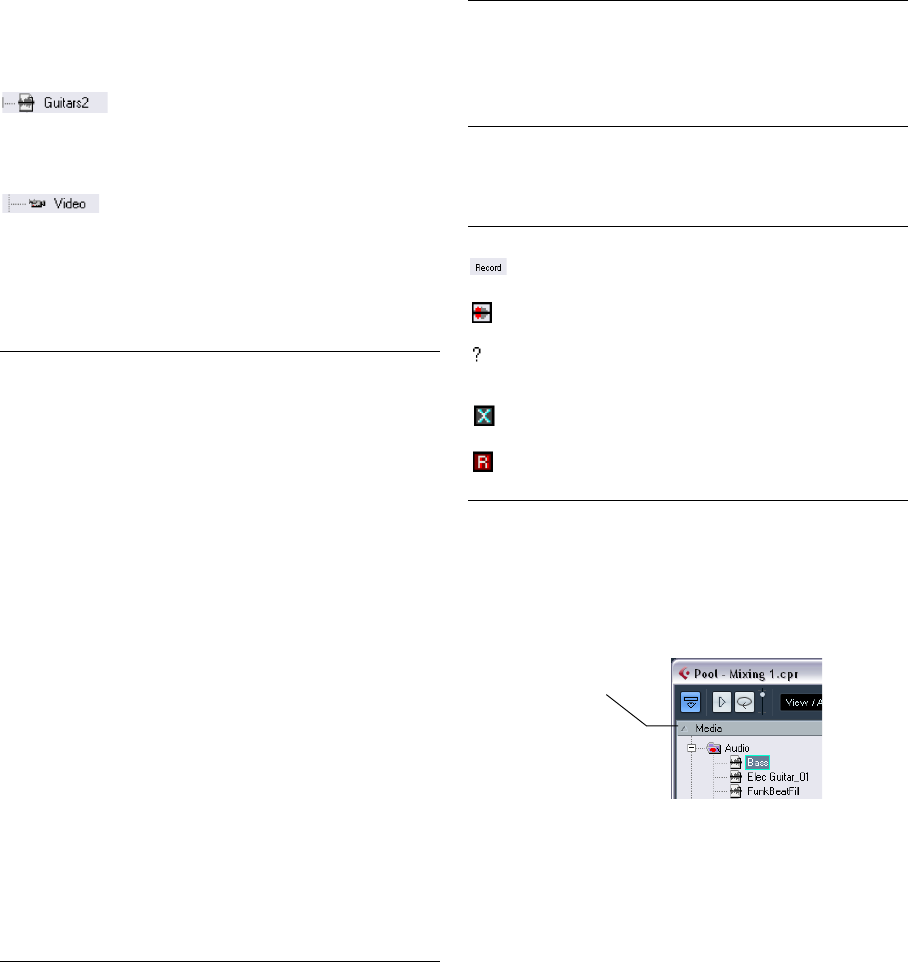
145
The Pool
How clips are displayed in the Pool
• Audio clips are represented by a waveform icon followed by
the clip name.
• Video clips are represented by a camera icon followed by the
clip name.
The Pool window columns
Various information about the clips can be viewed in the
Pool window columns. The columns contain the following
information:
About the Status column symbols
The Status column can display various symbols that relate
to the clips status. The following symbols can be shown:
Sorting the Pool contents
You can sort the clips in the Pool by name, date etc. This
is done by clicking on the corresponding column heading.
Clicking again on the same heading switches between as-
cending and descending sort order.
Column Description
Media This column contains the Audio, Video and Trash folders. If
the folders are opened, the clip names are shown and can
be edited. This column is always shown.
Used This column displays the number of times a clip is used in
the project. If there is no entry in this column, the corre-
sponding clip is not used.
Status This column displays various icons that relate to the cur-
rent Pool and clip status. See “About the Status column
symbols” on page 145 for a description of the icons.
Musical Mode The checkbox in this column allows you to activate or de-
activate Musical Mode. If the Tempo column (see below)
displays “???”, you have to enter the correct tempo be-
fore you can activate Musical Mode.
Tempo This shows the tempo of audio files, if available. If no
tempo has been specified, the column displays “???”.
Sign. This is the time signature, e.g. “4/4”.
Key This is the root key, if one was specified for the file.
Info This column shows the following information for audio
clips: The sample rate, bit resolution, number of channels
and the length in seconds. For video clips it displays the
frame rate, number of frames, and length in seconds.
Type This column shows the file format of the clip.
Date This column shows the date and time when the audio file
was last changed.
Origin Time This column shows the original start position where a clip
was recorded in the project. This value can be used as a
basis for the option “Insert into Project” in the Media or
context menu (and other functions).
Image This column displays waveform images of audio clips.
Path This column shows the path to the location of a clip on
the hard disk.
Reel Name Audio files may include this attribute, which is then shown
in this column. The Reel Name describes the “physical”
reel or tape from which the media was originally captured.
Symbol Description
This indicates the current Pool Record folder (see
“Changing the Pool Record folder” on page 152).
This symbol is shown if a clip has been processed.
The question mark indicates that a clip is referenced in
the project but missing from the Pool (see “About mis-
sing files” on page 149).
This indicates that the clip file is external, i.e. located out-
side the current Audio folder for the project.
This indicates that the clip has been recorded in the cur-
rently open version of the project. This is useful for finding
recently recorded clips quickly.
Column Description
The arrow indicates the sort
column and sort order.
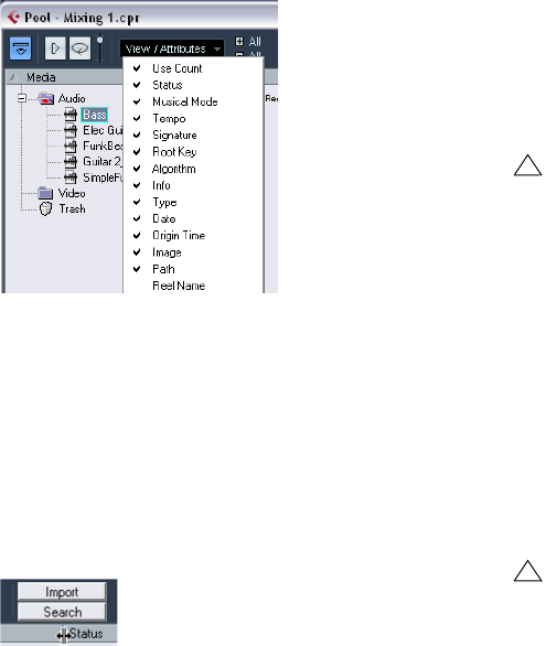
146
The Pool
Customizing the view
•You can specify which of the columns are shown or hid-
den by opening the View/Attributes pop-up menu on the
toolbar and selecting/deselecting items.
•You can rearrange the order of the columns by clicking
on a column heading and dragging the column to the left
or right.
The mouse pointer changes to a hand when you place it on the column
heading.
•The width of a column can also be adjusted by placing
the pointer between two column headers and dragging
left or right.
The pointer changes to a divider when you place it between two column
headers.
Operations
ÖMost of the Pool-related main menu functions are also
available on the Pool context menu (opened by right-click-
ing in the Pool window).
Renaming clips in the Pool
To rename a clip in the Pool, select it and click on the ex-
isting name, type in a new name and press [Return].
ÖThis will also rename the referenced files on disk!
Duplicating clips in the Pool
To duplicate a clip, proceed as follows:
1. Select the clip you wish to copy.
2. Select “New Version” on the Media menu.
A new version of the clip appears in the same Pool folder, with the same
name but with a “version number” after it, to indicate that the new clip is a
duplicate. The first copy made of a clip will get the version number “2” and
so on.
Inserting clips into a project
To insert a clip into a project, you can either use the Insert
commands on the Media menu or use drag and drop.
Using menu commands
Proceed as follows:
1. Select the clip(s) you want to insert into the project.
2. Pull down the Media menu and select an “Insert into
Project” option.
“At Cursor” will insert the clip(s) at the current project cursor position.
“At Origin” will insert the clip(s) at their Origin Time position(s).
!
Renaming a clip in the Pool is much preferred to re-
naming it outside Cubase AI (for example on the com-
puter desktop). This way, Cubase AI already “knows”
about the change, and will not lose track of the clip the
next time you open the project. See “About missing
files” on page 149 for details about lost files.
!
Duplicating a clip does not create a new file on disk,
but a new edit version of the clip (referring to the same
audio file).
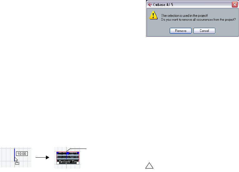
147
The Pool
•Note that the clip will be positioned so that its snap
point is aligned with the selected insert position.
You can also open the Sample Editor for a clip by double-clicking it, and
perform the insert operation from there. This way you can set the snap
point before inserting a clip.
3. The clip is inserted on the selected track or on a new
audio track.
If several tracks are selected, the clip will be inserted on the first selected
track.
Using drag and drop
When using drag and drop to insert clips into the Project
window, please note the following:
•Snap is taken into account if activated.
•While you drag the clip in the Project window, its position
is indicated by a marker line and a numerical position box.
Note that these indicate the position of the snap point in the clip. For ex-
ample, if you drop the clip at the position 10.00, this will be where the snap
point ends up. See “Adjusting the snap point” on page 129 for information
on how to set the snap point.
•If you position the clip in an empty area in the event dis-
play (i.e. below existing tracks), a new track is created for
the inserted event.
Deleting clips
Removing clips from the Pool
To remove a clip from the Pool without deleting it from the
hard disk, proceed as follows:
1. Select the clip(s) and select “Delete” from the Edit
menu (or press [Backspace] or [Delete]).
A prompt asks whether you want to move the clip to the Trash or remove
it from the Pool.
•If you try to delete a clip that is used by one or more
events, the program will ask you whether to remove these
events from the project.
If you cancel, neither the clip nor the associated events are deleted.
2. In the window that appears, select “Remove from Pool”.
The clip is no longer associated with the project, but still exists on the hard
disk and can be used in other projects, etc. This operation can be undone.
Deleting from the hard disk
To delete a file permanently from the hard disk, it must first
be moved to the Trash folder:
1. Follow the instructions for deleting clips above, but click
the Trash button instead of the Remove from Pool button.
Alternatively, you can drag and drop clips into the Trash folder.
2. On the Media menu, select “Empty Trash”.
A warning message is displayed.
3. Click “Erase” to delete the file on the hard disk perma-
nently.
This operation cannot be undone!
ÖTo retrieve a clip from the Trash folder, drag it back
into an Audio or Video folder.
Removing unused clips
This function finds all clips in the Pool that are not used in
the project. You can then decide whether to move them to
the Trash folder (from where they can be permanently de-
leted) or to remove them from the Pool:
1. Select “Remove Unused Media” on the Media or con-
text menu.
A message appears asking you whether you want to move the file to the
Trash or to remove it from the Pool.
2. Make your selection.
Snap point
!
Before you permanently delete audio files from the
hard disk, make sure that they are not used by another
project!
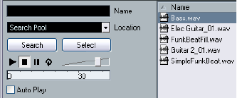
148
The Pool
Locating events and clips
Locating events via clips in the Pool
If you want to find out which events in the project refer to a
particular clip in the Pool, proceed as follows:
1. Select one or more clips in the Pool.
2. Select “Select in Project” on the Media menu.
All events that refer to the selected clip(s) are now selected in the Project
window.
Locating clips via events in the Project window
If you want to find out which clip belongs to a particular
event in the Project window, proceed as follows:
1. Select one or more events in the Project window.
2. Pull down the Audio menu and select “Find Selected
in Pool”.
The corresponding clip(s) are located and highlighted in the Pool.
Searching for audio files
The search functions can help you locate audio files in the
Pool, on your hard disk or on other media. This works
much like the regular file search, but with a couple of extra
features:
1. Click the Search button in the toolbar.
A search pane appears at the bottom of the window, displaying the
search functions.
The search pane in the Pool
By default, the search parameters available in the search
pane are “Name” and “Location”. For using other filter cri-
teria, see “Extended Search functionality” on page 148.
2. Specify the name of the file(s) to search for in the
Name field.
You can use partial names or wildcards (*). Note that only audio files of
the supported formats will be found.
3. Use the Location pop-up menu to specify where to
search.
The pop-up menu will list all your local drives and removable media.
•If you want to limit the search to certain folders, choose
“Select Search Path” and select the desired folder in the
dialog that appears.
The search will include the selected folder and all subfolders. Note also
that folders you have recently selected using the “Select Search Path”
function will appear on the pop-up menu, allowing you to quickly select
them again.
4. Click the Search button.
The search is started and the Search button is labeled Stop – click this
to cancel the search if needed.
When the search is finished, the files found are listed to
the right.
•To audition a file, select it in the list and use the play-
back controls to the left (Play, Stop, Pause and Loop).
If Auto Play is activated, selected files will automatically be played back.
•To import a file into the Pool, double-click on it in the list
or select it and click the Import button.
5. To close the search pane, click the Search button in
the toolbar again.
Extended Search functionality
Apart from the search criterion Name, additional search fil-
ters are available. The Extended Search options allows for
a very detailed search, helping you to master even the
largest sound database.
To use them, proceed as follows:
1. Click the Search button on the toolbar.
The Search pane is displayed in the lower part of the Pool window.

149
The Pool
2. Move the mouse pointer over the “Name” text to the
right of the name field and click on the arrow that appears.
3. The Extended Search pop-up menu opens.
It contains six options determining which search criterion is displayed
above the Location field (Name, Size, Bitsize, Channels, Sample Rate or
Date), as well as the Add Filter and Presets submenus.
The search criteria have the following parameters:
• Name: partial names or wildcards (*)
• Size: Less than, More than, Equal, Between (two values), in
seconds, minutes, hours and bytes
• Bitsize (resolution): 8, 16, 24, 32
• Channels: Mono, Stereo and from 3 to 16
• Sample Rate: various values, choose “Other” for free setting
• Date: various search ranges
4. Select one of the search criteria in the pop-up menu to
change the search option above the Location pop-up
menu.
5. If you want to display more search options, select the
desired element from the “Add filter” submenu.
This allows you, for example, to add the Size or the Sample Rate parame-
ters to the already displayed Name and Location parameters.
•You can save presets of your search filter settings. To
do this, click Save Preset on the Presets submenu and
enter a name for the preset.
Existing presets can be found at the bottom of the list. To remove a pre-
set, click on the preset to activate it, then select Remove Preset.
The Find Media window
Alternatively to the search pane in the Pool, you can open a
stand-alone Find Media window by selecting the “Search
Media…” option from the Media or context menu (also
available from the Project window). This offers the same
functionality as the search pane.
•To insert a clip directly into the project from the Find
Media window, select it in the list and choose one of the
“Insert into Project” options from the Media menu.
The options are described in the section “Inserting clips into a project”
on page 146.
About missing files
When you open a project, the Resolve Missing Files dialog
(see below) may open, warning you that one or more files
are “missing”. If you click Close, the project will open any-
way, without the missing files. In the Pool, you can check
which files are considered missing. This is indicated by a
question mark in the Status column.
A file is considered missing under one of the following
conditions:
•The file has been moved or renamed outside the pro-
gram since the last time you worked with the project, and
you ignored the Resolve Missing Files dialog when you
opened the project for the current session.
•You have moved or renamed the file outside the pro-
gram during the current session.
•You have moved or renamed the folder in which the
missing files are located.
Move the mouse pointer over
the “Name” text to the right of
the name field and click…
…to show the Extended Search pop-up menu.
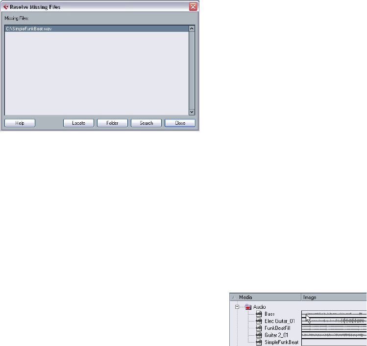
150
The Pool
Locate missing files
1. Select “Find Missing Files…” from the Media or con-
text menu.
The Resolve Missing Files dialog opens.
2. Decide if you want the program to try to find the file for
you (Search), if you want to do it yourself (Locate) or if you
want to specify in which directory the program should
search for the file (Folder).
•If you select Locate, a file dialog opens, allowing you to
locate the file manually.
Select the file and click “Open”.
•If you select Folder, a dialog opens to let you specify the
directory in which the missing file can be found.
This might be the preferred method if you have renamed or moved the
folder containing the missing file, but the file still has the same name. Once
you select the correct folder, the program finds the file and you can close
the dialog.
•If you select Search, a dialog opens to let you specify
which folder or disk should be scanned by the program.
Click the Search Folder button, select a directory or a disk and click the
Start button. If found, select the file from the list and click “Accept”.
Afterwards Cubase AI tries to map all other missing files automatically.
Reconstructing missing edit files
If a missing file cannot be found (e.g. if you have acciden-
tally deleted it from the hard disk), it will normally be indi-
cated with a question mark in the Status column in the
Pool. However, if the missing file is an edit file (a file cre-
ated when you process audio, stored in the Edits folder
within the project folder), it may be possible for the pro-
gram to reconstruct it by recreating the editing to the orig-
inal audio file.
Proceed as follows:
1. Open the Pool and locate the clip(s) for which files are
missing.
2. Check the Status column – if it says “Reconstruct-
ible”, the file can be reconstructed by Cubase AI.
3. Select the reconstructible clips and select “Recon-
struct” from the Media menu.
The editing is performed and the edit files are recreated.
Removing missing files from the Pool
If the Pool contains audio files that cannot be found or re-
constructed, you may want to remove these. For this, select
“Remove Missing Files” from the Media or context menu.
This will remove all missing files from the Pool as well as the
corresponding events from the Project window.
Auditioning clips in the Pool
There are three ways to audition clips in the Pool:
•By using key commands.
If you activate the “Playback Toggle triggers Local Preview” option in the
Preferences (Transport page), you can use [Space] to audition. This is
the same as clicking the Audition icon on the toolbar.
•By selecting a clip and activating the Audition button.
The whole clip will play back, unless you stop playback by clicking the
Audition button again.
•By clicking somewhere in the waveform image for a clip.
The clip will play from the position in the waveform you click until the end
of the clip, unless you stop playback by clicking the Audition button, or
by clicking anywhere else in the Pool window.
Click in the waveform image to audition a clip.
The audio is routed directly to the Main Mix (the default
output) bus, bypassing the audio channel’s settings, ef-
fects and EQs.
ÖYou can adjust the auditioning level with the miniature
level fader on the toolbar. This does not affect the regular
playback level.
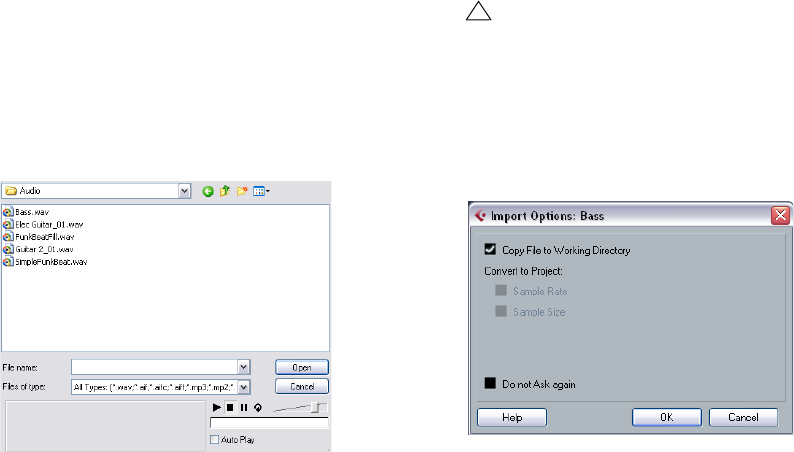
151
The Pool
If you have activated the Audition Loop button before you
audition, the following will happen:
•When you click the Audition button to audition a clip,
the clip is repeated indefinitely until you stop playback by
clicking the Audition or Audition Loop button again.
•When you click in the waveform image to audition, the
section from the point you clicked to the end of the clip is
repeated indefinitely until you stop playback.
Opening clips in the Sample Editor
The Sample Editor allows you to perform detailed editing
on the clip (see “The Sample Editor” on page 124). You
can open clips in the Sample Editor directly from the Pool
in the following way:
•If you double-click a clip waveform icon or a clip name
in the Media column, the clip opens in the Sample Editor.
One practical use for this is to set a snap point for a clip
(see “Adjusting the snap point” on page 129). When you
later insert the clip from the Pool into the project, you can
have it be properly aligned according to the set snap point.
About the Import Medium dialog
The Import Medium dialog lets you import files directly into
the Pool. It is opened from the Media or context menu or
using the Import button in the Pool window.
This is a standard file dialog, where you can navigate to
other folders, audition files, etc. The following audio file
formats can be imported:
• Wave (Normal or Broadcast, see “Broadcast Wave files” on
page 230)
• AIFF and AIFC (Compressed AIFF)
•REX or REX 2 (see “Importing ReCycle files” on page 258)
• SD2 (Sound Designer II)
• MPEG Layer 3 (mp3 files – see “Importing compressed audio
files” on page 258)
• Windows Media Audio (Windows – see “Importing com-
pressed audio files” on page 258)
They may have the following characteristics:
•Stereo or mono
• Any sample rate (although files with another sample rate than
the one used in the project will play back at the wrong speed
and pitch – see below).
• 8, 16, 24 bit or 32 bit float resolution
The following videos formats can also be imported:
• AVI (Audio Video Interleaved)
• MOV and QT (QuickTime)
•DV (Mac OS X only)
• MPEG 1 and 2 video files
ÖIt is also possible to use the commands on the Import
submenu on the File menu to import audio or video files
into the Pool.
When you select a file in the Import Medium dialog and
click Open, the Import Options dialog opens.
!
For video files to be played back correctly, the right
codecs have to be installed.
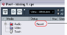
152
The Pool
It contains the following options:
•Copy File to Working Directory
Activate this if you want a copy of the file to be made in the Audio folder of
the project, and have the clip refer to this copy. If the option is off, the clip
will refer to the original file in the original location (and will thus be marked
as “external” in the Pool – see “About the Status column symbols” on
page 145).
•Convert to Project section
Here you can choose to convert the sample rate (if the sample rate is dif-
ferent than the one set for the project) or the sample size, i.e. resolution
(if the sample size is lower than the record format used in the project).
The options are only available if necessary. Note that if you are importing
several audio files at once, the Import Options dialog will instead contain
a “Convert and Copy to Project if needed” checkbox. When this is acti-
vated, the imported files will be converted only if the sample rate is differ-
ent or the sample size is lower than the project’s.
•Do not Ask again
If this is activated, files will always be imported according to the settings
you have made, without this dialog appearing. This can be reset in the
Preferences (Editing–Audio page).
ÖYou can always convert files later by using the Convert
Files (see “Convert Files” on page 153) or Conform Files
(see “Conform Files” on page 154) options.
Changing the Pool Record folder
All audio clips that you record in the project will end up in
the Pool Record folder. The Pool Record folder is indicated
by the text “Record” in the Status column and by a red dot
on the folder itself. By default, this is the main Audio folder.
You can, however, at any time create a new Audio sub-
folder and designate this as your Pool Record folder.
To do this, proceed as follows:
1. Select the Audio folder or any audio clip.
You cannot designate the Video folder (or any of its subfolders) as the
Pool Record folder.
2. Select “Create Folder” on the Media or context menu.
A new empty subfolder named “New Folder” appears in the Pool.
3. Select the new folder and rename it as desired.
4. Select “Set Pool Record Folder” on the Media or con-
text menu, or click in the Status column of the new folder.
The new folder now becomes the Pool Record folder, and any audio re-
corded in the project will be saved in this folder.
Organizing clips and folders
If you accumulate a large number of clips in the Pool, it
may sometimes be difficult to quickly find specific items. In
such cases, organizing clips in new subfolders with suit-
able names that reflect the content can be a solution. For
example, you could put all sound effects in one folder, all
lead vocals in another, etc. Proceed as follows:
1. Select the type of folder, audio or video, for which you
want to create a subfolder.
You cannot put audio clips in a video folder and vice versa.
2. Select “Create Folder” on the Media or context menu.
A new empty subfolder named “New Folder” appears in the Pool.
3. Rename the folder as desired.
4. Drag and drop the clips you wish to move to the new
folder.
5. Repeat steps 1–4 as necessary.
Applying processing to clips in the Pool
You can apply audio processing to clips from within the
Pool in the same way as to events in the Project window.
Simply select the clip(s) and choose a processing method
from the Audio menu. To find out more about audio pro-
cessing, see the chapter “Audio processing and functions”
on page 117.
Undoing processing
If you have applied processing to a clip, in the Project win-
dow, the Sample Editor, or in the Pool, this is indicated by
the red and gray waveform symbol in the Status column.
Freeze Edits
You can use the Freeze Edits function to create a new file
with processing applied or to replace the original with a
processed version, see “Freeze Edits” on page 123.
The Pool Record
folder
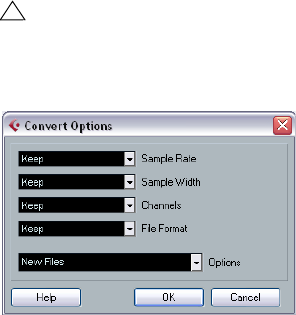
153
The Pool
Minimize File
The option “Minimize File” on the Media or context menu
allows you shrink the audio files according to the size of
the audio clips referenced in a project. The files produced
using this option only contain the audio file portions actu-
ally used in the project. This can significantly reduce the
size of the project, if large portions of the audio files are
unused. Therefore, the option is useful for archiving pur-
poses after you have completed a project.
ÖThis operation will permanently alter the selected au-
dio files in the Pool. This cannot be undone!
If this is not what you want, you can use the option “Back up Project” on
the File menu instead, see “Back up Project” on page 256. This function
also has the option of minimizing files, but copies all files into a new
folder, leaving the original project untouched.
Proceed as follows:
1. Select the file(s) you wish to minimize.
2. Select “Minimize File” on the Media menu.
An alert appears, informing you that the entire Edit History will be cleared.
Click Minimize to proceed or Cancel to stop the process.
3. After the minimizing is finished, another alert appears,
because the file references in the stored project have be-
come invalid.
Click Save Now to save the updated project or click Later to proceed
with the unsaved project.
Only the audio portions actually used in the project remain
in the corresponding audio file(s) in the Pool Record folder.
Prepare Archive
The option “Prepare Archive” on the Media menu is useful
if you want to archive a project. It verifies that every clip
referenced in the project is located in the same folder, and
takes actions if that is not the case:
•Any files that are located outside the current project
folder will be copied into it.
Please note that audio files residing within the project folder will not be
copied to the audio folder. You will therefore have to copy them there
manually before backing up the audio folder or save them separately dur-
ing backup, see below.
•If any processing has been applied, you will be asked
whether you want to Freeze Edits.
If you do this, you do not have to archive the Edits folder. Everything be-
longing to the project will be contained in the project file and the Audio
folder.
Once you have performed a Prepare Archive, you can copy
the project file, the Audio folder and any other audio mate-
rial you saved in the project folder to a different location,
e.g. a backup disk.
It is not necessary to archive the Images folder, since these
Images can be recreated by Cubase AI. You may also find a
file with the extension “.csh” in the project folder. This con-
tains image information for edited clips and other data that
can be recreated, so it can safely be deleted.
Convert Files
Selecting the option “Convert Files” on the Media or con-
text menu opens the Convert Options dialog which oper-
ates on selected files. Use the pop-up menus to specify
which audio file attributes you want to keep and which you
want to convert. The available settings are:
•Sample Rate
Keep as is, or convert to a sample rate between 8.000 and 96.000 kHz.
•Sample Width
Keep the sample width (resolution) as is, or convert to 16 Bit, 24 Bit or
32 Bit Float.
•Channels
Keep as is, or convert the file to Mono or Stereo Interleaved.
•File Format
Keep as is, or convert to Wave or AIFF format.
!
Video clips are always referenced and not stored in
the project folder.

154
The Pool
Options
When you convert a file, you can use the Options pop-up
to set one of the following options regarding what to do
with the new file:
Conform Files
By using this command, you will change all selected files
that have different file attributes than what is specified for
the project, to conform to this standard.
Proceed as follows:
1. Select the clips in the Pool.
2. Select “Conform Files…” on the Media menu.
A dialog opens allowing you to choose between keeping or replacing the
original unconverted files in the Pool.
The following applies:
• Clip/event references in the Pool are always redirected to the
conformed files.
• If any “keep” option is selected, original files remain in the
Project’s Audio folder and new files are created.
• If you select the “Replace” option, files in the Pool and in the
Project’s Audio folder are replaced.
Option Description
New Files Creates a copy of the file in the audio folder and converts
this new file according to the chosen attributes. The new
file is added to the Pool, but all clip references will still
point to the original, unconverted file.
Replace Files Converts the original file without changing clip refer-
ences. The references are however saved with the next
save action.
New +
Replace in
Pool
Creates a new copy with the chosen attributes, replaces
the original file with the new one in the Pool and redirects
the current clip references from the original file to the new
file. This is the option to select if you want your audio clips
to refer to the converted file, but still want to keep the orig-
inal file on disk (e.g. if the file is used in other projects).
15
Working with Track Presets
156
Working with Track Presets
Introduction
Track presets are templates from audio, MIDI or instrument
tracks that can be applied to newly created or existing
tracks of the same type. They contain sound and channel
settings, thus allowing you to quickly browse, preview, se-
lect and change sounds, or reuse channel settings across
projects.
Types of track presets
There are four kinds of track presets (audio, instrument,
MIDI and Multi) and two kinds of VST presets (VST Instru-
ment presets and VST effect plug-in presets). These are
described in the following sections.
ÖNote that volume and pan will be restored only when
creating a new track from a track preset.
Audio track presets
Track presets for audio tracks include all settings that “de-
fine” the sound. You can use the factory presets as a
starting point for your own editing and save the audio set-
tings that you optimized for an artist you often work with as
a preset for future recordings.
The following data will be saved in audio track presets:
• Insert FX settings (including VST effect presets)
•EQ settings
• Volume + Pan
Instrument track presets
Instrument track presets offer both MIDI and audio features
and are best choice when handling sounds of simple,
mono-timbral VST Instruments. Use instrument track pre-
sets for auditioning your tracks, inspiration, or saving your
preferred sound settings. You can directly extract sounds
from instrument track presets for use in instrument tracks.
The following data will be saved in instrument track presets:
•Audio Insert FX
•Audio EQ
• Audio Volume + Pan
•MIDI Track Parameters
•VST Instrument
• Staff settings
• Color settings
• Drum map settings
MIDI track presets
MIDI tracks should be used for multi-timbral VST Instru-
ments. When creating MIDI track presets you can either in-
clude the currently set channel, or the currently set patch.
See “Creating a track preset” on page 158 for details.
The following data will be saved in MIDI track presets:
• MIDI Modifiers (Transpose, etc.)
• Output + Channel or Program Change
•Volume + Pan
• Staff settings
• Color settings
• Drum map settings
Multi track presets
You can use multi track presets e.g. when recording setups
that require several microphones (a drum set or a choir,
where you record always under the same conditions) and
have to edit the resulting tracks in a similar way, or for lay-
ered tracks, where you use several tracks to generate a
certain sound instead of manipulating only one track.
If you select more than one track when creating a track
preset, the settings of all selected tracks will be saved as
one multi track preset. Since you can apply a multi track
preset only if the target tracks are of the same type, num-
ber and sequence as the tracks in the track preset, multi
track presets are useful when you have a recurring situa-
tion with very similar tracks and settings.
VST (Instrument) presets
VST Instrument presets (extension .vstpreset) are VST
presets that behave like instrument track presets in the
context of the Project window and contain a VST Instru-
ment and its settings but no modifiers, inserts or EQ set-
tings. You can directly extract sounds from VST presets
for use in instrument tracks.
The following data is saved in VST Instrument presets:
•VST Instrument
•VST Instrument settings
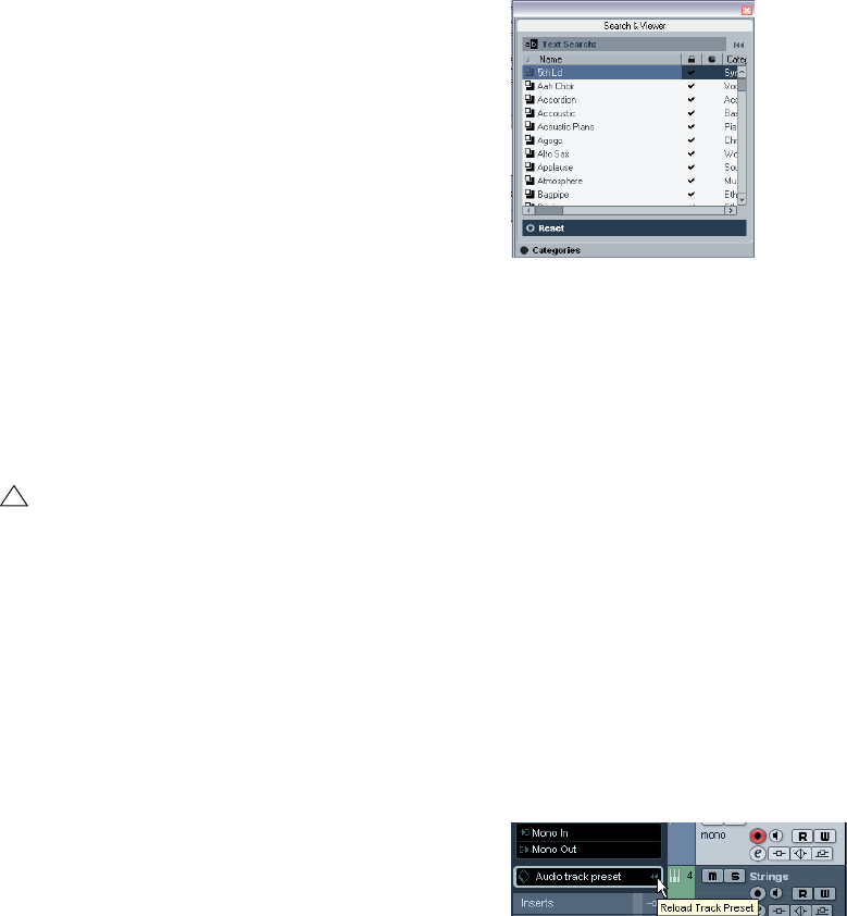
157
Working with Track Presets
VST effect plug-ins are available in VST3 and VST2 for-
mat. Presets for these effects are also saved as VST pre-
sets. These that can be part of audio track presets (see
“Audio track presets” on page 156).
ÖIn this manual, “VST presets” stands for VST3 Instru-
ment presets, unless stated otherwise.
Applying track presets
When you apply a track preset, all saved settings are ap-
plied, see “Types of track presets” on page 156. Track
presets can be applied to tracks of their own type only, i.e.
audio track presets to audio tracks, etc. The only excep-
tion are instrument tracks: for these VST presets are also
available. Note that applying VST presets to instrument
tracks leads to removal of modifiers, inserts or EQs, since
these settings are not stored in VST presets, see “Previe-
wing MIDI, instrument and VST presets independently of
tracks” on page 159.
Applying track or VST presets via drag and drop
1. Open the Save Track Preset dialog for the desired
track type and select a preset.
2. Drag and drop it onto a track of the same type.
ÖYou can also drag and drop track presets from the
Windows Explorer or the Mac OS Finder.
Applying track or VST presets in the Inspector
or the context menu of the track
1. Select a track in the Project window.
2. Click the VST Sound button in the Inspector or right-
click the track to open the context menu and select “Apply
Track Preset”.
The Presets browser opens. Here, the files are presented in list form.
3. Select a track or VST preset from the list.
If needed, activate the Categories option in order to show a customiz-
able filter section.
4. Click outside the browser to apply the selected preset
or click the Reset button below the list to return to the un-
changed track.
Applying a multi track preset
1. Select several tracks in your project.
The selected tracks have to be of the same type, number and sequence
as the tracks in the track preset.
2. Right-click the track to open the context menu and se-
lect “Apply Track Preset”.
The Presets browser opens. Only multi track presets corresponding to
the selection of tracks in the project will be shown.
3. Select a multi track preset from the list.
4. Click outside the browser to apply the selected preset
or click the Reset button below the list to return to the un-
changed track.
Reloading track or VST presets
To revert to the default settings of the applied preset, click
the “Reload Track Preset” button.
!
Once a track preset is applied, you cannot undo the
changes! It is not possible to remove an applied pre-
set from a track and return to the previous state. If you
are not satisfied with the track settings, you can either
edit the settings manually or apply another preset.
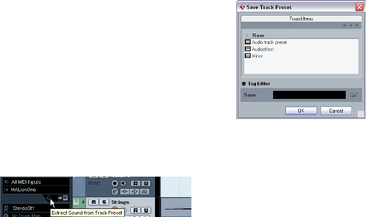
158
Working with Track Presets
Applying Inserts and EQ settings from track
presets
Instead of handling complete track presets, it is also pos-
sible to apply Insert or Equalizer settings from track pre-
sets:
1. Select the desired track, open the Inspector or the
Channel Settings window and click the VST Sound button
on the Inserts or Equalizers tab/section.
The presets pop-up menu is opened.
2. Select “From Track Preset…” in the pop-up menu.
The Presets browser opens, showing all available track presets that con-
tain Inserts or EQ settings.
3. Select the track preset with the desired Inserts or EQs
and click outside the browser.
For information on the general handling of Inserts presets,
see “Effect presets” on page 94. The general handling of
EQ presets is described in the section “Using EQ pre-
sets” on page 79.
Extracting sound from an instrument track or
VST preset
For instrument tracks, you can extract the “sound” of an
instrument track preset or VST preset, that means the VST
Instrument and its settings.
Proceed as follows:
1. Select the instrument track to which you want to apply
a sound.
2. Click the VST Sound button below the Output Rou-
ting field in the Inspector.
The Presets browser opens, showing a list of all available
presets.
3. Select an instrument track preset or VST preset by
double-clicking on it.
The VST instrument and its settings (but no inserts, EQs and modifiers)
of the existing track are overwritten with the data of the track preset. The
previous VST instrument for this instrument track is removed and the new
VST instrument with its settings is set up for the instrument track.
ÖThe VST instrument of an instrument track does not
show up in the VST Instrument window but only in the
Plug-In Information window, see the section “The Plug-in
Information window” on page 97.
Creating a track preset
A track preset is created from an existing audio, MIDI or
instrument track – or several of these tracks. Proceed as
follows:
1. Select one or more tracks in the Project window.
If several tracks are selected, all of them are stored in one combined
multi track preset, see “Multi track presets” on page 156.
2. Right-click one of the selected tracks in the Track list to
open the context menu and select “Create Track Preset”.
The Save Track Preset dialog opens.
3. Enter a file name in the “File Name” field.
The track preset file name extension .trackpreset is assigned automatically.
•If you selected a MIDI track, you can include either the
MIDI channel or the MIDI patch in your track preset.
ÖIf you want to use a MIDI track preset for a pre-config-
ured VST Instrument setup, load the VST Instrument(s) in
the VST Instruments window, select a VST Instrument
patch, save the track preset and do not change the patch
afterwards. To ensure this, use a template project with the
VSTi setup included and save the sounds (track presets)
of this template project in specific subfolders, as they only
work within this setup.
4. Open the “Tag Editor” by clicking on the correspond-
ing option and edit the tags.
5. Click OK to create the track preset.

159
Working with Track Presets
Track presets are saved within the application folder in the
“Track Presets” folder (in default subfolders named accord-
ing to their track type: audio, MIDI, instrument and multi).
Creating tracks from track presets
or VST presets
Using drag and drop
1. Open the Save Track Preset dialog for the desired
track type and select a preset.
2. Drag and drop the preset onto the Track list in the
Project window.
One or more (in case of multi track presets) tracks will be created. If you
drag and drop a VST instrument preset, this will result in an instrument
track.
ÖYou can also drag and drop from the Windows Ex-
plorer or the Mac OS Finder.
Using the Browse Sounds dialog
1. Right-click the Track list to open the context menu and,
on the Add Track submenu, select “Browse Sounds…”.
The Browse Sounds dialog with all available presets opens.
2. Select a track or VST preset from the list of all presets.
At this point you can preview selected MIDI and instrument track presets
as well as VST presets, see “Previewing MIDI, instrument and VST presets
independently of tracks” on page 159. If you want to list a certain track pre-
set type only, open the respective folder in the Browser section.
3. Click OK to create one or more (in case of multi track
presets) tracks.
Using the Add Track function
1. Right-click the Track list to open the context menu and
select the desired option on the context menu.
•If you want to create more than one track of the same
type, enter the number in the Count field.
2. Click “Browse Presets” to open the Browse Presets
section of the “Add Track” dialog with the search pane
and a list of all available presets.
The view is filtered to show only the corresponding track presets.
•If you want to see the contents of presets subfolders
within the VST Sound node, click the “Show Location”
option to open the Browser section.
3. Select a track or VST preset.
4. Click OK to create the track.
Notice that the new track will not be named after the track preset.
ÖThis method is not available for multi track presets.
Previewing MIDI, instrument and
VST presets independently of tracks
1. Open the “Browse Sounds” dialog and select a MIDI,
an instrument track or a VST preset.
2. Make sure the “In ‘All MIDI Inputs’” option is activated
for your MIDI input device (default setting).
Only MIDI data incoming via “All MIDI Inputs” is used for preview.
3. Click the MIDI Input button.
4. Play some MIDI notes via your MIDI input device, for
example a keyboard.
The Activity meter on the far right mirrors the MIDI in activity.
!
You cannot change the default folders, but you can
add further subfolders, e.g. “drums” and “choir”.
16
Remote controlling Cubase AI
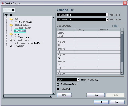
161
Remote controlling Cubase AI
Introduction
It is possible to control Cubase AI via MIDI. A large num-
ber of MIDI control devices is supported. This chapter de-
scribes how to set up Cubase AI for remote control. The
supported devices are described in the separate PDF
document “Remote Control Devices”.
•There is also a Generic Remote Device option, allowing
you to use any MIDI controller to remote control Cubase AI.
How to set this up is described in the section “The Generic Remote de-
vice” on page 163.
Setting Up
Connecting the remote device
Connect the MIDI Out on the remote unit to a MIDI In on
your MIDI interface. Depending on the remote unit model,
you may also need to connect a MIDI Out on the interface
to a MIDI In on the remote unit (this is necessary if the re-
mote unit features “feedback devices” such as indicators,
motorized faders, etc.).
If you will be recording MIDI tracks, you do not want any
MIDI data from the remote unit to accidentally be recorded
as well. To avoid this, you should also make the following
setting:
1. Open the Device Setup dialog from the Devices menu.
2. Select “MIDI Port Setup” in the list to the left.
3. Check the table to the right and locate the MIDI input
to which you have connected the MIDI remote unit.
4. Deactivate the checkbox in the “In ‘All MIDI Inputs’”
column for that input, so that the State column reads “In-
active”.
5. Click OK to close the Device Setup dialog.
Now you have removed the remote unit input from the “All
MIDI Inputs” group. This means that you can record MIDI
tracks with the “All MIDI Inputs” port selected without risk-
ing to record the data from the remote unit at the same time.
Selecting a remote device
1. Pull down the Devices menu and select Device Setup.
A dialog window opens with a list of device categories and devices shown
in the left part of the window.
2. If you cannot find the remote device you are looking
for, click on the plus sign in the top left corner and select
the device from the pop-up menu.
The selected device is added to the Devices list.
•Note that it is possible to select more than one remote
device of the same type.
If you have more than one remote device of the same type, these will be
numbered in the Devices list. For example, to be able to use a Mackie
Control Extender, you must install a second Mackie control device.
3. Now select your MIDI control device model from the
Devices list.
Depending on the selected device, either a list of programmable function
commands or a blank panel is shown in the right half of the dialog window.
A Yamaha 01x selected as remote control device.
4. Select the correct MIDI input from the pop-up menu.
If necessary, select the correct MIDI output from the pop-up menu.
5. Click OK to close the dialog.
You can now use the MIDI control device to move faders and knobs, ac-
tivate Mute and Solo, etc. The exact parameter configuration depends on
which external MIDI control device you are using.
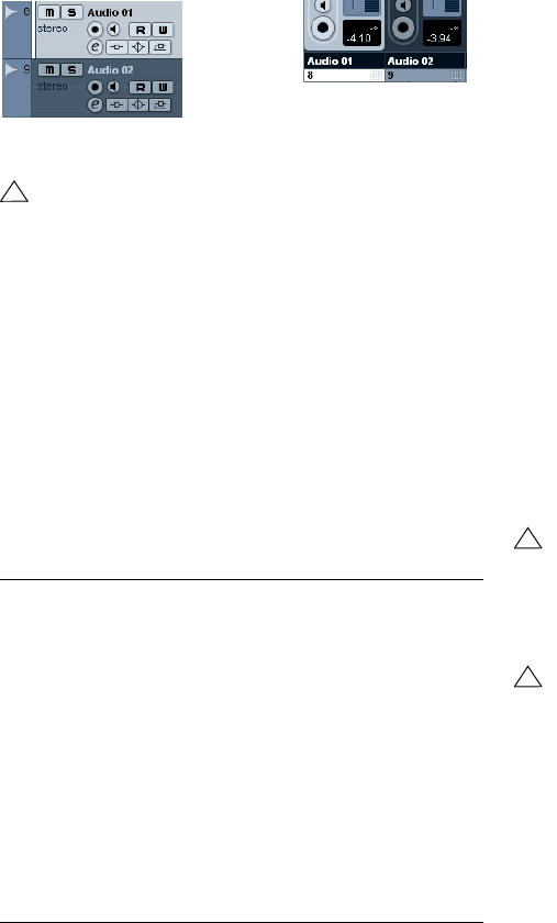
162
Remote controlling Cubase AI
•In the Project window (Track list) and the mixer (bottom
of channel strips) you will now see white stripes indicating
which channels are currently linked to the remote control
device.
Audio 01 can be remote controlled, while Audio 02 is not linked to the
remote control device.
Operations
Global options for remote controllers
In the Device Setup dialog, on the page for your remote
device, some (or all) of the following global functions may
be available (depending on your remote device):
Writing automation using remote controls
Automating the mixer using a remote control device is done
in the same way as when you operate on-screen controls in
Write mode. However, when it comes to replacing existing
automation data, there is one important difference:
•If you activate Write mode and move a control on the re-
mote control device, all data for the corresponding para-
meter is replaced from the position where you moved the
control, up until the position where playback is stopped!
In other words, as soon as you move a control in Write mode, it remains
“active” until you stop playback. The reason for this is explained below.
As a consequence, an additional precaution must be taken:
•Make sure you move only the controller you want to re-
place!
In order to replace existing automation data for a control,
the computer needs to know how long the user actually
“grabbed” or used the control. When doing this “on
screen”, the program simply detects when the mouse but-
ton is pressed and released. When you are using an exter-
nal remote control device, however, there is no mouse
button involved, and Cubase AI cannot tell whether you
“grab and hold” a fader, or simply move it and release it.
Instead, you have to indicate that you have “released” the
control by stopping playback.
!
Sometimes communication between Cubase AI and
a remote device is interrupted or the handshaking
protocol fails to create a connection. To re-establish
communication with any device in the Devices list,
select it and click the Reset button in the Device
Setup dialog. Also, the “Send Reset Message to all
Devices” button at the top of the dialog will reset ev-
ery device in the Devices list.
Option Description
Reset This allows you to revert to the factory default settings for
the remote device.
Bank If your remote device contains several banks, you can se-
lect the bank you want to use on this pop-up menu.
The bank you select here will be the one used by default
when Cubase AI is launched.
Smart Switch
Delay Some of the Cubase AI functions (e.g. Solo and Mute)
support the so called “smart switch” behavior: In addition
to regular activation/deactivation of a function by clicking
a button, you can also activate the function for as long as
the button is pressed. Upon releasing the mouse button,
the function is deactivated.
This pop-up menu allows you to specify how long a button
must be pressed before it goes into “smart switch” mode.
When “Off” is selected, the “smart switch” function is de-
activated in Cubase AI.
!
The above does not apply to the Mackie Control or
any other remote control device with touch sensitive
controls. These devices will stop writing as they have
touch sensitive faders, which means that they stop
writing as soon as you release the fader.
!
This is only relevant when you are using a remote con-
trol device and Write mode is activated in the mixer.
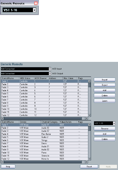
163
Remote controlling Cubase AI
Assigning remote key commands
For some of the supported remote devices, you can assign
any Cubase AI function (to which a key command can be
assigned) to generic buttons, wheels or other controls. As
of this writing, these devices are:
•Tascam US-428
• Yamaha 01x
• Yamaha DM 2000v2
• Yamaha DM 1000v2
•Steinberg Houston
Proceed as follows:
1. Open the Device Setup dialog and select one of the
remote devices that support this feature.
On the right side of the window you will find a three column table. This is
where you assign commands.
2. Use the “Button” column to locate a remote device con-
trol or button to which you wish to assign a Cubase AI func-
tion.
3. Click in the “Category” column for the control, and se-
lect one of the Cubase AI function categories from the
pop-up menu.
4. Click in the “Command” column, and select the desired
Cubase AI function from the pop-up menu.
The available items on the pop-up menu depend on the selected category.
5. Click “Apply” when you are done.
The selected function is now assigned to the button or
control on the remote device.
A note about remote controlling MIDI tracks
While most remote control devices will be able to control
both MIDI and audio channels in Cubase AI, the parame-
ter setup may be different. For example, audio-specific
controls (such as EQ) will be disregarded when control-
ling MIDI channels.
The Generic Remote device
If you have a generic MIDI controller, you can use this for
remote control of Cubase AI by setting up the Generic
Remote device:
1. Open the Device Setup dialog on the Devices menu.
If the Generic Remote device is not on the Devices list, you need to add it.
2. Click the “+” sign in the top left corner and select the
“Generic Remote” device from the pop-up menu.
•When the Generic Remote device is added in the Device
Setup dialog, you can open the corresponding window by
selecting “Generic Remote” from the Devices menu.
The Generic Remote window
3. Select the Generic Remote device in the Devices list
to the left.
The settings for the Generic Remote device are displayed, allowing you
to specify which control on your device should control which parameter
in Cubase AI.
4. Use the MIDI Input and Output pop-up menus to se-
lect the MIDI port(s) to which your remote device is con-
nected.

164
Remote controlling Cubase AI
5. Use the pop-up menu to the right to select a bank.
Banks are combinations of a certain number of channels, and are used be-
cause most MIDI devices can control only a limited number of channels at
a time (often 8 or 16). For example, if your MIDI control device has 16 vol-
ume faders, and you are using 32 mixer channels in Cubase AI, you would
need two banks of 16 channels each. When the first bank is selected you
control channel 1 to 16; when the second Bank is selected you control
channel 17 to 32. Since you can control Transport functions as well, you
may need several banks.
6. Set up the table at the top according to the controls
on your MIDI control device.
The columns have the following functionality:
•If you find that the table at the top holds too many or too
few controls, you can add or remove controls with the Add
and Delete buttons to the right of the table.
•If you are uncertain of which MIDI message a certain
controller sends, you can use the Learn function.
Select the control in the upper table (by clicking in the Control Name co-
lumn), move the corresponding control on your MIDI device and click the
Learn button to the right of the table. The MIDI Status, MIDI Channel and
Address values are automatically set to those of the moved control.
7. Use the table at the bottom to specify which Cubase
AI parameters you want to control.
Each row in the table is associated to the controller in the corresponding
row in the first table (as indicated by the Control Name column). The
other columns have the following functionality:
8. If necessary, make settings for another bank.
Note that you only need to make settings in the bottom table for this bank.
The table at the top is already set up according to the MIDI remote device.
•If necessary, you can add banks by clicking the Add
button below the Bank pop-up.
Clicking the Rename button allows you to assign a new name to the cur-
rently selected bank, and you can remove an unneeded bank by selecting it
and clicking the Delete button.
Column Description
Control Name Double-clicking this field allows you to enter a descriptive
name for the control (typically a name written on the con-
sole). This name is automatically reflected in the Control
Name column in the lower table.
MIDI Status Clicking in this column pulls down a pop-up menu, allow-
ing you to specify the type of MIDI message sent by the
control. The options are Controller, Program Change, Note
On, Note Off, Aftertouch and Polyphonic Pressure. Also
available are Continuous Control NRPN and RPN, a way
to extend the available control messages. The “Ctrl JLCoo-
per” option is a special version of a Continuous Controller
where the 3rd byte of a MIDI message is used as address
instead of the 2nd byte (a method supported by various
JL-Cooper remote devices).
MIDI Channel Clicking in this column opens a pop-up menu, allowing
you to select the MIDI channel on which the controller is
transmitted.
Address The Continuous Controller number, the pitch of a note or
the address of a NRPN/RPN Continuous Controller.
Max. Value The maximum value the control will transmit. This value is
used by the program to “scale” the value range of the MIDI
controller to the value range of the program parameter.
Flags Clicking in this column pulls down a pop-up menu, allow-
ing you to activate or deactivate three flags:
Receive – activate this if the MIDI message should be
processed on reception.
Transmit – activate this if a MIDI message should be trans-
mitted when the corresponding value in the program
changes.
Relative – activate this if the control is an “endless” rotary
encoder, which reports the number of turns instead of an
absolute value.
Column Description
Device Clicking in this column pulls down a pop-up menu, used
for determining which device in Cubase AI should be
controlled. The special option “Command” allows you to
perform certain command actions by remote control. One
example of this is the selection of remote banks.
Channel/
Category This is where you select the channel to be controlled or, if
the “Command” Device option is selected, the Command
category.
Value/Action Clicking in this column pulls down a pop-up menu, allow-
ing you to select the parameter of the channel to be
controlled (typically, if the “VST Mixer” Device option is
selected you can choose between volume, pan, send
levels, EQ, etc.).
If the “Command” Device option is selected, this is where
you specify the “Action” of the category.
Flags Clicking in this column pulls down a pop-up menu, allow-
ing you to activate or deactivate three flags:
Push Button – When activated, the parameter is only
changed if the received MIDI message shows a value
unequal to 0.
Toggle – When activated, the parameter value is switched
between minimum and maximum value each time a MIDI
message is received. The combination of Push Button and
Toggle is useful for remote controls which do not latch the
state of a button. One example is controlling mute status
with a device on which pressing the Mute button turns it
on, and releasing the Mute button turns it off. If Push But-
ton and Toggle are activated, the Mute status will change
between on and off whenever the button is pressed on the
console.
Not Automated – When activated, the parameter will not
be automated.
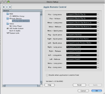
165
Remote controlling Cubase AI
9. When you are finished, close the Device Setup window.
Now, you can control the specified Cubase AI parameters from the MIDI
remote device. To select another bank, use the pop-up menu in the Re-
mote Status window (or use a control on the MIDI remote device, if you
have assigned one for this).
Importing and exporting remote setups
The Export button in the top right corner of the Generic
Remote Setup window allows you to export the current
setup, including the Control configuration (the table at the
top) and all banks. The setup is saved as a file (with the file
extension “.xml”). Clicking the Import button allows you to
import saved remote setup files.
•The last imported or exported remote setup will auto-
matically be loaded when the program starts or the Ge-
neric Remote control is added in the Device Setup dialog.
Apple Remote (Macintosh only)
Many Apple computers come with an Apple Remote Con-
trol, a small hand-held device akin to TV remote controls. It
allows you to remotely control certain features in Cubase
AI.
1. Open the Device Setup dialog and select Apple Re-
mote Control from the Add Device pop-up.
2. In the list on the right, the Apple Remote’s buttons are
listed. For each button you can open a pop-up menu from
which you can select a Cubase AI parameter.
The parameter you select will be assigned to the corresponding button
on the Apple Remote.
By default, the Apple Remote always controls the applica-
tion that currently has the focus on your Macintosh com-
puter (provided that this application supports the Apple
Remote).
•When the option “Disable when application is not in
front” is not selected, the Apple Remote will control Cu-
base AI even if it does not have the focus.
17
MIDI realtime parameters
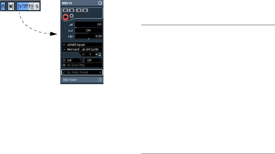
167
MIDI realtime parameters
Introduction
For each MIDI track, you can set up a number of track pa-
rameters, or modifiers. These affect how the MIDI data is
played back, “transforming” MIDI events in realtime before
they are sent to the MIDI outputs.
On the following pages, the available parameters are de-
scribed. Keep in mind:
• The actual MIDI events will not be affected – the changes
happen “on the fly”.
• Since the modifier settings do not change the actual MIDI
data on the track, they will not be reflected in the MIDI editors.
To convert the track settings into “real” MIDI events, use the
Freeze MIDI Modifiers function (see “Permanent settings with
Freeze MIDI Modifiers” on page 176).
The Inspector – General handling
The MIDI modifiers are set up in the Inspector. Here’s a
brief rundown on how to handle the Inspector:
•To show or hide the Inspector, click the Inspector icon
on the Project window toolbar.
The Inspector for a MIDI track
•For a MIDI track, up to three sections are available.
Which of these sections are displayed in the Inspector is
determined in the setup context menu or the Setup dialog
of the Inspector.
For information about setting up the Inspector, see “Using the Setup op-
tions” on page 262.
•You can fold or unfold the sections individually by click-
ing on the section name.
Clicking the name for a hidden section brings it to view and hides the
other sections. [Ctrl]/[Command]-clicking the tab allows you to hide or
show a section without affecting other sections. [Alt]/[Option]-clicking a
tab shows or hides all sections in the Inspector.
ÖFolding or hiding (via the Setup dialog) a section does
not affect the functionality but merely hides the section
from view.
This means your settings will still be active even if you fold or hide the In-
spector settings.
The Inspector sections
Apart from the basic track settings in the topmost Inspector
section (see below), the Inspector for a MIDI track also con-
tains the following sections: MIDI Modifiers, MIDI Fader and
one for a connected VST Instrument. These are described
below.
Basic track settings
These are settings that either affect the basic functionality
for the track (mute, solo, enable record, etc.) or send out
additional MIDI data to the connected devices (program
change, volume, etc.). The section contains all settings in
the Track list (see “The Track list” on page 17), with a few
additional parameters:
Parameter Description
Track name
field Click once to show/hide the topmost Inspector section.
Double-click to rename the track.
Edit button This opens the Channel Settings window for the track (a
window showing a channel strip with volume fader and
other controls, along with effect settings – see “Using
Channel Settings” on page 76).
Mute/Solo
buttons Mutes or solos the MIDI track.
Read/Write
buttons Used for automating the track settings – see “Enabling
and disabling the writing of automation data” on page 109.
Record enable
button Activate this to make the track ready for recording.
Monitor button When this is activated (and the option “MIDI Thru Active”
is activated in the Preferences–MIDI page), incoming
MIDI will be routed to the selected MIDI output.
Volume Use this to adjust the level for the track. Changing this set-
ting will move the track’s fader in the mixer window, and
vice versa. See “Setting volume in the mixer” on page 74
for details about setting levels.
Pan Use this to adjust the panning of the track.
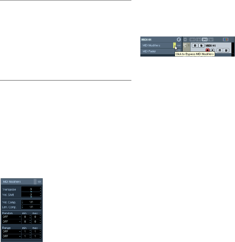
168
MIDI realtime parameters
ÖNote that the functionality of the Bank and Patch selec-
tor settings (used for selecting sounds in the connected
MIDI instrument) depends on the instrument to which the
MIDI output is routed, and how you have set it up in the
MIDI Device Manager.
The MIDI Device Manager allows you to specify which MIDI instruments
and other devices are connected to the various MIDI outputs, thus mak-
ing it possible to select patches by name.
ÖMany of the basic track settings are duplicated in
“mixer channel strip form” in the MIDI Fader section of the
Inspector (see below).
MIDI Modifiers
The settings on this tab affect the MIDI events on the track
in realtime during playback. They will also be in effect if you
play “live” with the track selected and record enabled (pro-
vided that “MIDI Thru Active” is activated on the Prefer-
ences–MIDI page). This makes it possible, for example, to
transpose or adjust the velocity of your live playing.
ÖIf you want to compare the result of your modifier set-
tings with the “unprocessed” MIDI, you can use the Bypass
button in the MIDI Modifiers section.
When this is activated, the MIDI Modifiers settings will be temporarily
disabled. A bypassed section is indicated by a yellow Bypass button.
Transpose
This allows you to transpose all notes on the track in semi-
tones. The available range is -127 to +127 semitones, but
remember that the total range of MIDI note numbers is 0
to 127. Furthermore, not all instruments can play back
notes over the whole range. Therefore, extreme transposi-
tions can give rather strange and unwanted results.
•You can also transpose individual MIDI parts using the
Transpose field in the info line.
The transposition in the info line (for the individual part) is added to the
transpose value you have set up for the whole track in the Inspector.
Velocity Shift
This setting lets you change the dynamics of all notes on
the track. The value in this field is added to the velocity of
each note message that is sent out (use negative values to
lower the velocities). The range is -127 to +127 with 0
representing no change in velocity.
Note that the effect of changing the velocity depends on
the sound and instrument.
ÖYou can also adjust the velocity of events in individual
MIDI parts using the Velocity field in the info line.
The velocity shift in the info line (for the individual part) is added to the
velocity shift you have set up for the whole track in the Inspector.
Velocity Compression
This function multiplies the velocity values with the factor
you specify. This factor is set using a numerator (left value)
and a denominator (right value), resulting in a fractional
number (1/2, 3/4, 3/2 etc.). For example, if you set the fac-
tor to 3/4, the velocities will be three quarters of their origi-
nal values. This will also affect the difference in velocity
between the notes, thus compressing or expanding the ve-
locity scale. Typically, you would combine this setting with
the Velocity Shift parameter.
Delay This adjusts the playback timing of the MIDI track. Positive
values delay the playback while negative values cause the
track to play earlier. The values are set in milliseconds.
In/Out/Chn
pop-ups This is where you select MIDI input, MIDI output and MIDI
channel for the track.
Edit Instru-
ment button If the MIDI track is routed to a VST instrument, clicking this
button opens the control panel for the VST instrument.
Bank and
Patch Selec-
tor pop-up
Allows you to select a sound, see below. (If no bank is
available, only the Patch selector is shown.)
Apply Track
Preset button Allows you to apply a track preset, see “Applying track
presets” on page 157.
Parameter Description

169
MIDI realtime parameters
An example:
Let’s say you have three notes with the velocity values 60,
90 and 120, and wish to “even out” the velocity differences
somewhat. If you set the Velocity Compression value to 1/
2, the notes will play back with the velocities 30, 45 and 60.
By adding 60 in the Velocity Shift field, the notes will play
back with the velocities 90, 105 and 120, meaning you
have compressed the velocity range.
In a similar way, you can use Velocity Compression values
greater than 1/1 together with negative values in the Ve-
locity Shift field, to expand the velocity range.
Length Compression
This value adjusts the lengths of all notes on the track. As
with Velocity Compression, the value is set with a numer-
ator and denominator. For example, the value 2/1 means
that all note lengths will be doubled, while 1/4 means all
note lengths will be a quarter of the actual lengths.
Random
The Random settings let you introduce random variations
to various properties of MIDI notes. Anything from very
subtle variations to dramatic changes can be applied.
There are two separate “random generators”, set up in the
following way:
1. Pull down the Random pop-up menu and select which
note property should be randomized.
The options are position, pitch, velocity and length.
ÖKeep in mind that depending on the content of the
track, certain parameter changes might not be immediately
noticeable or have any effect at all (as would be the case if
applying random length to a percussion track playing “one-
shot” samples for example).
To best audition the random changes, choose a track with clearly defined
rhythm and note content (as opposed to a string pad).
2. Set the desired range of random deviation by entering
values in the two number fields.
The two values govern the limits of the randomization, so that the values
will vary between the left value and the right value (you cannot set the left
value higher than the right value). The maximum random range for each
property is listed in the table below:
ÖYou can make independent settings for the two random
generators.
•To deactivate the Random function, pull down the Ran-
dom pop-up menu(s) and select “OFF”.
Range
The Range function lets you specify a note (pitch) or ve-
locity range and either force all notes to fit within this
range, or exclude all notes outside this range from play-
back. As with the Random function, there are two sepa-
rate Range settings. Set them up as follows:
1. Pull down the Range pop-up menu and select one of
the following four modes:
!
Remember that the maximum velocity is always 127
no matter how much you try to expand.
Property Range
Position -500 to +500 ticks
Pitch -120 to +120 semitones
Velocity -120 to +120
Length -500 to +500 ticks
Mode Description
Vel. Limit This function affects all velocity values outside the speci-
fied range. Velocity values below the Min setting (the lower
limit of the range) are set to the Min value, and velocity val-
ues above the Max setting are set to the Max value. Notes
with velocity values within the set range are not affected.
Use this if you want to force all velocity values to fit within a
certain range.
Vel. Filter Velocity Filter works by excluding all notes with velocity
values outside the specified range. Notes with velocity
values below the Min setting or above the Max setting will
not be played back. Use this to “isolate” notes with cer-
tain velocity values.
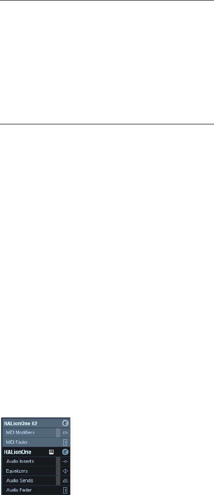
170
MIDI realtime parameters
2. Use the two fields to the right to set the minimum and
maximum values.
These values will be shown as numbers (0–127) for the velocity modes
and as note numbers (C-2 to G8) for the pitch modes.
ÖNote that you can make independent settings for the
two Range functions.
•To deactivate the Range function, pull down the Range
pop-up menu(s) and select “OFF”.
MIDI Fader section
This contains a single channel strip, allowing you to set
volume, pan, mute/solo and other parameters for the track,
and a panel view of the active sends/inserts. This is a “mir-
ror” of the track’s channel strip in the Cubase AI mixer –
see “The MIDI channel strips” on page 73.
VST Instrument section
If the MIDI track is routed to a VST Instrument, a new sub-
panel will appear at the bottom of the Inspector, labeled
with the name of the VST instrument. Clicking this section
shows a duplicate of the Inspector settings for the VST In-
strument channel. This makes it easy to adjust the channel
settings for the VST Instrument while you are editing the
MIDI track.
•If the VST Instrument has multiple outputs (and thus
several mixer channels), there will be a setting called
“Output” at the top of the VST Instrument section.
New sub-panels will also be added in the following cases:
• When a MIDI track is routed to an effect plug-in that also re-
ceives audio data, i.e. that is used as an insert effect for an au-
dio track (e.g. MIDI Gate), a sub-panel for this audio track
appears in the MIDI track inspector.
• If a MIDI track is routed to a plug-in assigned to a FX Channel
track, a corresponding FX sub-panel is added to the Inspector.
ÖFor an easy way to combine MIDI and VST instruments,
check out instrument tracks (see “VST Instruments and In-
strument tracks” on page 99).
Note Limit This function allows you to specify a pitch range, and
forces all notes to fit within this range. Notes outside the
specified range are transposed up or down in octave
steps until they fit within the range.
Note: If the range is too “narrow”, so that some notes
cannot be fit within the range by octave-transposing,
these notes will get a pitch in the middle of the range. For
example, if you have a note with a pitch of F3, and the
range is C4-E4, that note will be transposed to D4.
Note Filter Note Filter works by excluding all notes with pitches out-
side the specified range. Notes lower than the Min set-
ting or higher than the Max setting will not be played
back. Use this to “isolate” notes with certain pitches.
Mode Description
18
MIDI processing and quantizing
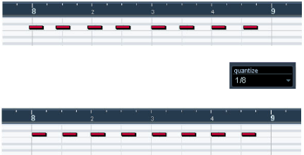
172
MIDI processing and quantizing
Introduction
This chapter describes the various MIDI processing func-
tions available on the MIDI menu. They offer various ways
to edit MIDI notes and other events, either in the Project
window or from within a MIDI editor.
MIDI functions vs. MIDI modifiers
In some cases, the result of a MIDI function can also be
obtained by using MIDI modifiers (see “MIDI realtime pa-
rameters” on page 166). For example, the operations
“Transpose” and “Quantize” are available both as MIDI
modifiers and as MIDI functions.
The main difference is that MIDI modifiers do not affect the
actual MIDI events on the track in any way, while MIDI func-
tions change the events “permanently” (although recent
changes can be undone).
Use the following guidelines to decide which path to
choose for operations that are available both as modifiers
and as functions:
•If you want to adjust a few parts or events only, use MIDI
functions. The MIDI modifiers affect the output of the
whole track.
•If you want to experiment with different settings, use
MIDI modifiers.
•MIDI modifiers settings are not reflected in the MIDI edi-
tors, since the actual MIDI events are not affected. This can
be potentially confusing; if you have transposed notes using
modifiers for example, the MIDI editors will still show the
notes with their original pitch (but they will play back at their
transposed pitch). Therefore, MIDI functions are a better
solution if you want to see the effects of your editing in the
MIDI editors.
What is affected by the MIDI functions?
Which events are affected when you use a MIDI function
depends on the function, the active window and the cur-
rent selection:
•Some MIDI functions only apply to MIDI events of a cer-
tain type.
For example, quantization only affects notes, while the Delete Controllers
function only applies to MIDI controller events.
•In the Project window, the MIDI functions apply to all
selected parts, affecting all events (of the relevant types)
in them.
•In the MIDI editors, the MIDI functions apply to all se-
lected events. If no events are selected, all events in the
edited part(s) will be affected.
The Quantizing functions
What is quantizing?
Quantizing in its fundamental form is a function that auto-
matically moves recorded notes, positioning them on ex-
act note values:
However, quantizing is not only a method of correcting er-
rors, it can also be used creatively in various ways. For ex-
ample, the “quantize grid” does not have to consist of
perfectly straight notes, some notes can automatically be
excluded from quantizing, etc.
ÖWhen quantizing MIDI, only MIDI notes are affected
(no other event types).
However, you can choose to move the controllers together with their re-
spective notes by activating the “Move Controller” option in the Quantize
Setup dialog, see “The Move Controller setting” on page 174.
For example, if you record a series of eighth notes, some of them may
end up slightly beside the exact eighth note positions.
Quantizing the notes with the quantize
grid set to eighth notes will move the
“misplaced” notes to exact positions.
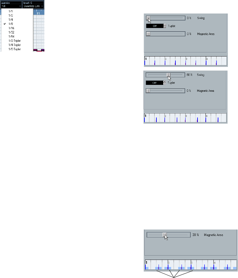
173
MIDI processing and quantizing
Setting up quantize on the toolbar
At its most basic, setting up quantizing consists of select-
ing a note value from the Quantize pop-up menu on the
toolbar (in the Project window or a MIDI editor).
This allows you to quantize to exact note values (straight,
triplet or dotted notes) only.
Setting up quantize in the Quantize Setup
dialog
If you want more options than those available on the pop-
up menu, select “Quantize Setup…” from the MIDI menu
(or “Setup…” from the Quantize pop-up menu) to open
the Quantize Setup dialog.
ÖAny settings you make in the dialog are immediately
reflected in the Quantize pop-up menus. However, if you
want your settings permanently available on the Quantize
pop-up menus, you have to use the presets functions (see
“Presets” on page 174).
The grid display in the middle of the dialog shows one bar
(four beats), with blue lines indicating the quantize grid
(the positions that notes will be moved to). Value changes
in the grid, presets and quantize options will be graphically
reflected here, see below.
The Quantize Setup dialog contains the following settings:
The Grid and Type pop-ups
These are used to determine the basic note value for the
quantizing grid. In other words, these have the same func-
tionality as the Quantize pop-up menu on the toolbar.
Swing
The Swing slider is only available when a straight note
value is selected for the grid and Tuplet is off (see below).
It lets you offset every second position in the grid, creating
a swing or shuffle feel. When you adjust the Swing slider,
the result is shown in the grid display.
A straight eighth note grid compared with a grid with 60% swing.
Tuplet
Allows you to create more rhythmically complex grids by
dividing the grid into smaller steps.
Magnetic Area
This allows you to specify that only notes within a certain
distance from the grid lines should be affected by quantiz-
ing.
•When the slider is set to 0%, the Magnetic Area func-
tion is deactivated, i.e. all notes are affected by quantizing.
If you move the slider gradually to the right, you will note how the mag-
netic areas are shown around the blue lines in the grid display.
Only notes within the indicated zones will be affected by quantizing.
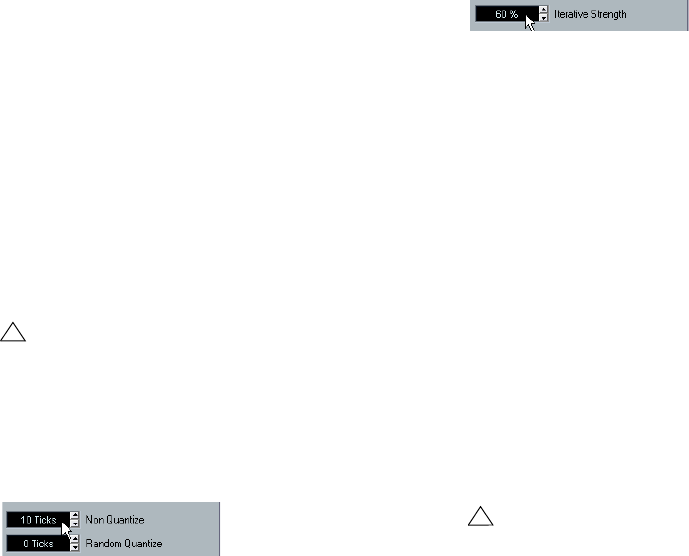
174
MIDI processing and quantizing
Presets
The controls in the lower left corner of the dialog allow you
to store the current settings as a preset, which will then be
available on the Quantize menus on the toolbars. The
usual preset procedures apply:
•To store the settings as a preset, click the Store button.
•To load a stored preset into the dialog, simply select it
from the pop-up menu.
This is useful if you want to modify an existing preset.
•To rename the selected preset, double-click on the
name and type in a new one.
•To remove a stored preset, select it from the pop-up
menu and click Remove.
Apply and Auto
These functions allow you to apply quantizing directly from
the dialog, see below.
The Non Quantize setting
This setting affects the result of the quantizing. It allows you
to set a “distance” in ticks (120ths of sixteenth notes).
Events that already are within the specified distance from
the quantize grid will not be quantized. This allows you to
keep slight variations when you quantize, but still correct
notes that are too far from the grid.
The Random Quantize setting
This setting affects the result of the quantizing. It allows you
to set a “distance” in ticks (120ths of sixteenth notes).
Events will be quantized to random positions within the
specified “distance” from the quantize grid, thus creating
a more “loose” quantizing. Much like the Non Quantize
setting, this allows for slight variations, while at the same
time keeping notes from ending up too far from the grid.
The Iterative Strength setting
Here you specify how much the notes should be moved
towards the grid when using the Iterative Quantize func-
tion, see below.
The Move Controller setting
When this is activated, controllers related to notes (pitch-
bend, etc.) are automatically moved with the notes when
these are quantized.
Applying quantize
There are several ways to apply the quantize:
•The standard method is to select “Over Quantize” from
the MIDI menu (or using a key command, by default [Q]).
This quantizes the selected MIDI parts or notes according to the current
Quantize pop-up menu setting.
•You can also apply quantizing directly from the Quantize
Setup dialog, by clicking the “Apply Quantize” button.
•If you activate the “Auto” checkbox in the Quantize Setup
dialog, any change you make in the dialog is immediately
applied to the selected MIDI parts or notes.
A great way of using this feature is to set up a playback loop, and adjust
the settings in the dialog until you get the desired result.
The Auto Quantize function
If you activate the Auto Q button on the Transport panel,
all MIDI recordings you make are automatically quantized
according to the settings you have made in the Quantize
Setup dialog.
!
If you do not want to apply the quantizing you have
set up in the dialog, close the window by clicking its
close button.
!
When you apply quantize, the result is based on the
original position of the notes. Therefore, you can
freely try out different quantize settings with no risk of
“destroying” anything (see also “Undo Quantize” on
page 175).
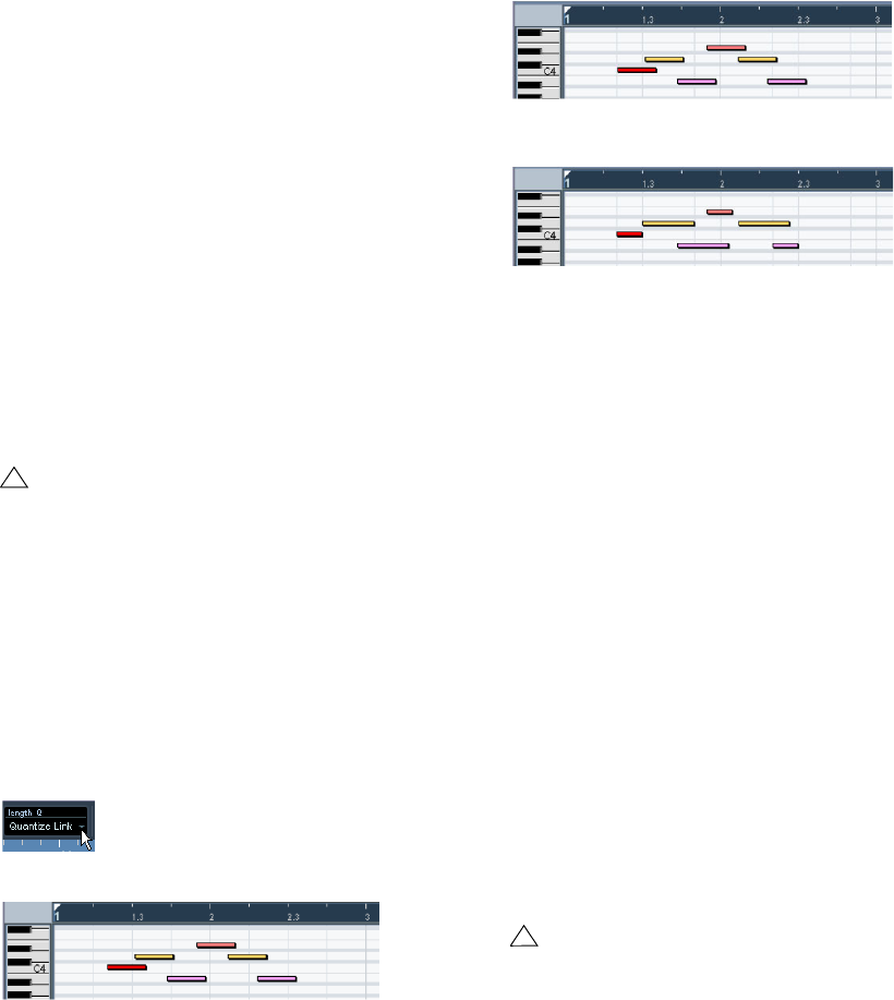
175
MIDI processing and quantizing
Iterative Quantize
Another way to apply “loose” quantization is to use the Iter-
ative Quantize function on the MIDI menu. It works like this:
Instead of moving a note to the closest quantize grid posi-
tion, Iterative Quantize moves it only part of the way. You
specify how much the notes should be moved towards the
grid with the “Iterative Strength” setting in the Quantize
Setup dialog.
Iterative Quantize also differs from “regular” quantization
in that the operation is not based on the notes’ original po-
sitions but on their current, quantized position. This makes
it possible to repeatedly use Iterative Quantize, gradually
moving the notes closer to the quantize grid until you have
found the desired timing.
Advanced Quantize functions
Quantize Lengths
This function (on the Advanced Quantize submenu on the
MIDI menu) will quantize the length of the notes, without
changing their start positions. At its most basic level, this
function will set the length of the notes to the Length
Quantize value on the MIDI editor toolbar. However, if you
have selected the “Quantize Link” option on the Length
Quantize pop-up menu, the function will resize the note
according to the quantize grid, taking the Swing, Tuplet
and Magnetic Area settings into account.
An example:
1. Length Quantize set to “Quantize Link”.
2. Some 16th notes.
3. Here, the quantize value has been set to straight 16th notes with
Swing at 100%.
4. Selecting Quantize Lengths will adjust the note lengths according to
the grid. If you compare the result to the first figure above, you will find
that notes that started within the odd sixteenth note “zones” show the
longer grid length, and notes in the even zones have the shorter length.
Quantize Ends
The Quantize Ends function on the Advanced Quantize
submenu will only affect the end positions of notes. Apart
from that, it works just like regular quantizing, taking the
Quantize pop-up menu setting into account.
Undo Quantize
As mentioned above, the original position of each quan-
tized note is stored. Therefore, you can make the selected
MIDI notes revert to their original, unquantized state at any
time by selecting Undo Quantize from the Advanced
Quantize submenu. This is independent from the regular
Undo History.
Freeze Quantize
There may be situations when you want to make the quan-
tized positions “permanent”. For example, you may want to
quantize notes a second time, having the results based on
the current quantized positions rather than the original po-
sitions. To make this possible, select the notes in question
and select “Freeze Quantize” from the Advanced Quantize
submenu. This makes the quantized positions permanent.
!
This function is only available from within the MIDI
editors.
!
After you have performed a Freeze Quantize for a
note, you cannot undo its quantization.
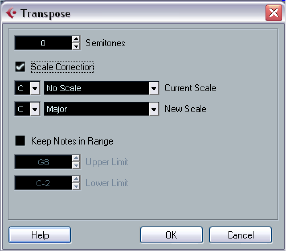
176
MIDI processing and quantizing
Transpose
The Transpose item on the MIDI menu opens a dialog with
settings for transposing the selected notes.
Semitones
This is where you set the amount of transposition.
Scale Correction
Scale Correction transposes the selected notes by for-
cing them to the closest note of the selected scale type.
This can be used for creating interesting key and tonal
changes, either by itself or in conjunction with the other
settings in the Transpose dialog.
•To activate Scale Correction, click the checkbox.
•Select a root note and scale type for the current scale
from the upper pop-up menus.
•Select a root note and scale type for the new scale from
the lower pop-up menus.
Make sure to select the correct root note if you want to keep the result in
the same key as the original notes, or select an entirely different key if you
want to experiment.
Keep Notes in Range
When this is activated, transposed notes will remain
within the Upper and Lower Limit values.
•If a note ends up outside the limits after transposition, it
will be shifted to another octave, keeping the correct
transposed pitch if possible.
If this is not possible (if you have set a very narrow range between the
Upper and Lower Limit), the note will be transposed “as far as possible”,
i.e. to the Upper or Lower Limit note. If you set the Upper and Lower Lim-
its to the same value, all notes will be transposed to this pitch!
OK and Cancel
Clicking OK performs the transposition. Clicking Cancel
closes the dialog without transposing.
Permanent settings with Freeze
MIDI Modifiers
The MIDI Modifier settings in the Inspector do not change
the MIDI events themselves, but work like a “filter”, affecting
the music on playback. Therefore, you may want to make
them permanent, i.e. convert them to “real” MIDI events, for
example to transpose a track and then edit the transposed
notes in a MIDI editor. For this, you can use the “Freeze
MIDI Modifiers” command from the MIDI menu. This applies
all filter settings permanently to the respective track.
The “Freeze MIDI Modifiers” function affects the following
settings for MIDI tracks:
• Several settings on the main tab of the Inspector (program
and bank selection and the Delay parameter).
• The settings on the MIDI Modifiers tab (i.e. Transpose, Veloc-
ity Shift, Velocity Compression and Length Compression).
The following settings for MIDI parts are taken into ac-
count as well:
• The Transpose and Velocity settings for parts displayed on the
info line – please note that the Volume setting is not taken into
account.
To use the “Freeze MIDI Modifiers” function, proceed as
follows:
1. Select the desired MIDI track.
2. Pull down the MIDI menu and select “Freeze MIDI
Modifiers”.
The Inspector settings will be converted to MIDI events and inserted at
the beginning of the part(s). All notes of the part(s) will be modified ac-
cordingly and the Inspector settings will be reset.
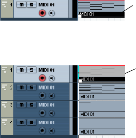
177
MIDI processing and quantizing
Dissolve Part
The Dissolve Part function on the MIDI menu allows you to
separate MIDI events according to channels or pitches:
•When you work with MIDI parts (on MIDI channel “Any”)
containing events on different MIDI channels, activate the
option “Separate Channels”.
•To separate MIDI events according to pitch, activate the
option “Separate Pitches”.
A typical example would be drum and percussion tracks, where different
pitches usually correspond to separate drum sounds.
ÖWhen dissolving a part into either separate channels
or separate pitches, you can automatically remove the si-
lent (empty) areas of the resulting parts by activating the
“Optimized Display” checkbox in the Dissolve Part dialog.
Dissolving parts into separate channels
Setting a track to MIDI channel “Any” will cause each MIDI
event to play back on its original MIDI channel, rather than
a channel set for the whole track. There are two main situ-
ations when “Any” channel tracks are useful:
•When you record several MIDI channels at the same
time.
You may for example have a MIDI keyboard with several keyboard zones,
where each zone sends MIDI on a separate channel. Recording on an
“Any” channel track allows you to play back the recording with different
sounds for each zone (since the different MIDI notes play back on sepa-
rate MIDI channels).
•When you have imported a MIDI file of Type 0.
MIDI files of Type 0 contain only one track, with notes on up to 16 different
MIDI channels. If you were to set this track to a specific MIDI channel, all
notes in the MIDI file would be played back with the same sound; setting
the track to “Any” will cause the imported file to play back as intended.
The Dissolve Part function scans MIDI parts for events on
different MIDI channels and distributes the events into new
parts on new tracks, one for each MIDI channel found. This
allows you to work with each musical part individually. Pro-
ceed as follows:
1. Select the parts containing MIDI data on different
channels.
2. Select “Dissolve Part” from the MIDI menu.
3. In the dialog that appears, select the “Separate Chan-
nels” option.
Now, for each MIDI channel used in the selected parts, a
new MIDI track is created and set to the corresponding
MIDI channel. Each event is then copied into the part on
the track with the corresponding MIDI channel. Finally, the
original parts are muted.
An example:
Dissolving parts into separate pitches
The Dissolve Part function can also scan MIDI parts for
events of different pitches, and distribute the events into
new parts on new tracks, one for each pitch. This is useful
when the different pitches are not used in a melodic con-
text, but rather for separating different sounds (e.g. MIDI
drum tracks or sampler sound FX tracks). By dissolving
such parts, you can work with each sound individually, on
a separate track.
Proceed as follows:
1. Select the parts containing MIDI data.
2. Select “Dissolve Part” from the MIDI menu.
3. In the dialog that appears, select the “Separate
Pitches” option.
A new MIDI track is created for each used pitch in the selected parts.
The events are then copied into the parts on the track for the corres-
ponding pitch. Finally, the original parts are muted.
This part contains
events on MIDI
channels 1, 2 and 3.
Selecting “Dissolve Part” creates new parts on new tracks, set to
channels 1, 2 and 3. Each new part contains only the events on the
respective MIDI channel.
The original MIDI part is
muted.
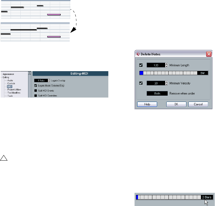
178
MIDI processing and quantizing
Other MIDI functions
The following items can be found on the Functions sub-
menu of the MIDI menu:
Legato
Extends each selected note so that it reaches the next note.
You can specify a gap or overlap for this function with the
“Legato Overlap” setting in the Preferences (Editing–MIDI
page).
When using Legato with this setting, each note will be extended to end
5 ticks before the next note.
When you activate “Legato Mode: Selected Only”, the
length of the note will be adjusted so that it reaches the
next selected note, allowing you e.g. to only apply Legato
to your bass line (when playing on a keyboard).
Fixed Lengths
This function resizes all selected notes to the length set
with the Length Quantize pop-up menu on the MIDI editor
toolbar.
Delete Doubles
This function removes double notes, i.e. notes of the same
pitch on the exact same position from the selected MIDI
parts. Double notes can occur when recording in Cycle
mode, after Quantizing, etc.
Delete Controllers
This function removes all MIDI controllers from the se-
lected MIDI parts.
Delete Continuous Controllers
This function removes all “continuous” MIDI controller
events from the selected MIDI parts. Therefore, “on/off”
events such as sustain pedal events are not removed.
Delete Notes
Allows you to delete very short or weak notes. This is use-
ful for automatically removing unwanted “ghost notes” af-
ter recording. Selecting “Delete Notes…” opens a dialog
in which you set up the criteria for the function.
The parameters have the following functionality:
Minimum Length
When the Minimum Length checkbox is activated, the note
length is taken into account, allowing you to remove short
notes. You can either specify the minimum length (for notes
to be kept) in the value field or by dragging the blue line in
the graphical length display below.
•The graphical length display can correspond to 1/4 bar,
one bar, two bars or four bars.
You change this setting by clicking in the field to the right of the display.
In this case, the whole length display corresponds to two bars, and the
Minimum Length is set to 32nd notes (60 ticks).
!
This function is only available from within the MIDI
editors.
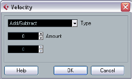
179
MIDI processing and quantizing
Minimum Velocity
When the Minimum Velocity checkbox is activated, the ve-
locity of notes is taken into account, allowing you to re-
move weak notes. You specify the minimum velocity (for
notes to be kept) in the value display.
Remove when under
This setting is only available when both Minimum Length
and Minimum Velocity is activated. By clicking in this field,
you select whether both the length and the velocity criteria
must be met for notes to be deleted, or whether one of the
criteria will suffice.
OK and Cancel
Clicking OK performs the automatic delete according to
the rules set up. Clicking Cancel closes the dialog without
deleting notes.
Restrict Polyphony
Selecting this item opens a dialog in which you can spec-
ify how many “voices” should be used (for the selected
notes or parts). Restricting the polyphony this way is use-
ful when you have an instrument with limited polyphony
and want to make sure all notes will be played. The effect
is achieved by shortening notes as required, so that they
end before the next note starts.
Pedals to Note Length
This function scans for Sustain pedal on/off events, length-
ens the affected notes to match the Sustain pedal off posi-
tion, and then removes the Sustain Controller on/off events.
Delete Overlaps (mono)
This function allows you to make sure that no notes of the
same pitch overlap (i.e. that one starts before the other
ends). Overlapping notes of the same pitch can confuse
some MIDI instruments (a new Note On is transmitted be-
fore the Note Off is transmitted). This command can then
be used to automatically solve the problem.
Delete Overlaps (poly)
This function shortens notes when required, so that no
note begins before another ends. This happens regard-
less of which pitch the notes have.
Velocity
This function opens a dialog that allows you to manipulate
the velocity of notes in various ways.
The following types of velocity processing are available:
Add/Subtract
This simply adds a fixed number to the existing velocity
values. You set the value (positive or negative) with the
Amount parameter.
Compress/Expand
Compresses or expands the “dynamic range” of MIDI
notes by scaling the velocity values according to the Ratio
setting (0–300%). The principle behind this is that multi-
plying different velocity values with a factor higher than 1
(over 100%) will also make the differences between ve-
locity values greater, while using a factor lower than 1 (un-
der 100%) will make the differences smaller. In short:
•To compress (“even out” velocity differences), use ratio
values below 100%.
After compression, you would probably want to add a velocity amount
(with the Add/Subtract function) to maintain the average velocity level.
•To expand (create greater difference in velocity), use ra-
tio values above 100%.
Before you expand, you may want to adjust the velocity with the Add/
Subtract function, so that the average velocity is somewhere in the mid-
dle of the range. If the average velocity is high (near 127) or low (near 0),
expansion will not work properly, simply because velocity values can only
be between 0 and 127!
Limit
This function allows you to make sure that no velocity val-
ues fall outside a given range (the Lower and Upper val-
ues). Any velocity values outside this range are raised/
lowered to exactly the Lower/Upper values.
180
MIDI processing and quantizing
Fixed Velocity
This function sets the velocity of all selected notes to the
Insert Velocity value on the toolbar in the MIDI editors.
Thin Out Data
Thins out MIDI data. Use this to ease the load on your ex-
ternal MIDI devices if you have recorded very dense con-
troller curves etc.
You can also manually thin out the controller data by using
the quantize function in the Key Editor.
Extract MIDI Automation
This is an extremely useful function as it allows you to
quickly and easily convert the continuous controllers of
your recorded MIDI parts into MIDI track automation data,
making them available for editing in the Project window.
Proceed as follows:
1. Select the desired MIDI part containing the continuous
controller data.
2. Select “Extract MIDI Automation”. (This command is
also available on the Key Editor context menu.)
The controller data will automatically be removed from the controller lane
in the editor.
3. In the Project window, open the automation track for
the respective MIDI track. When you select one the con-
tinuous controllers from the parameter pop-up menu, the
respective automation data will be displayed on the auto-
mation track.
This function can only be used for continuous controllers.
Data such as Aftertouch, Pitchbend or SysEx cannot be
converted to MIDI track automation data.
ÖRemember that to be able to hear the automation data,
you have to activate the Read button for the respective au-
tomation track(s).
Reverse
This function inverts the order of the selected events (or of
all events in the selected parts), causing the MIDI music to
play backwards. Note that the effect is different from re-
versing an audio recording. With MIDI, the individual notes
will still play as usual in the MIDI instrument – it is only the
order of playback that is changed.
19
The MIDI editors
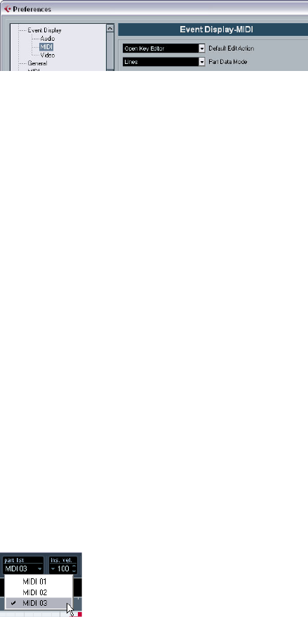
182
The MIDI editors
Introduction
There are several ways to edit MIDI in Cubase AI. You can
use the tools and functions in the Project window for large-
scale editing, or the functions on the MIDI menu to process
MIDI parts in various ways (see “What is affected by the
MIDI functions?” on page 172). For hands-on graphical ed-
iting of the contents of MIDI parts, you use the MIDI editors:
•The Key Editor is the default MIDI editor, presenting
notes graphically in an intuitive piano roll-style grid.
The Key Editor also allows for detailed editing of non-note events such as
MIDI controllers. For more information, see “The Key Editor – Overview” on
page 184.
•The Drum Editor is similar to the Key Editor, but takes
advantage of the fact that with drum parts, each key corre-
sponds to a separate drum sound.
This is the editor to use when you’re editing drum or percussion parts.
For more information, see “The Drum Editor – Overview” on page 199.
•The List Editor shows all events in the selected MIDI
parts as a list, allowing you to view and edit their properties
numerically. It also allows you to edit SysEx messages.
For more information, see “The List Editor – Overview” on page 206 and
“Working with System Exclusive messages” on page 210.
•The Score Editor shows MIDI notes as a musical score.
This offers basic score editing and printing – see “The Score Editor –
Overview” on page 213 for details).
ÖYou can define each of the editors mentioned above
as your default MIDI editor, see below.
Please note that features that are identical in these editors
(especially in the Key and Drum Editors) will be described
in the Key Editor section. The sections about the Drum Ed-
itor (see “The Drum Editor – Overview” on page 199), and
the List Editor (see “The List Editor – Overview” on page
206) describe the specific features of these editors only.
Opening a MIDI editor
There are two ways to open a MIDI editor:
•Select one or several parts (or a MIDI track, with no parts
selected), pull down the MIDI menu and select Open Key
Editor, Open Drum Editor, Open List Editor or Open Score
Editor from the Scores submenu (or use the corresponding
key command).
The selected parts (or all parts on the track, if no part was selected) will
open in the chosen editor.
•Double-click a part to open it in the default editor.
Which editor opens depends on the Default Edit Action setting in the
Preferences (Event Display–MIDI page).
If the option “Edit as Drums when Drum Map is assigned”
is activated and a drum map is selected for the edited
track (see “Selecting a drum map for a track” on page
204), the Drum Editor will open. This way you can double-
click to open the Key Editor (or the Score Editor or List
Editor, depending on your preferences) but drum tracks
will automatically open in the Drum Editor.
ÖIf the part you open for editing is a shared copy, any ed-
iting you perform will affect all shared copies of this part.
Shared copies are created by pressing [Alt]/[Option]-[Shift] and drag-
ging, or by using the Repeat function with the “Shared copies” option
activated. In the Project window, shared copies are indicated by the part
name in italics and an icon in the bottom right corner of the part.
Handling several parts
When you open a MIDI editor with several parts (or a MIDI
track containing several parts) selected, you might find it
somewhat hard to get an overview of the different parts
when editing.
For such cases the editor toolbar features a few functions
to make working with multiple parts easier and more com-
prehensive:
•The Part List menu lists all parts that were selected when
you opened the editor (or all parts on the track, if no parts
were selected), and lets you select which part should be
active for editing.
When you select a part from the list, it is automatically made active and
centered in the note display.
ÖNote that it is also possible to activate a part by select-
ing an event within this part with the Arrow tool.
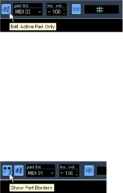
183
The MIDI editors
•The button “Edit Active Part Only” lets you restrict edit-
ing operations to the active part only.
For example, if you select “All” from the Select submenu on the Edit menu
with this option activated, only events in the active part will be selected.
Similarly, if you select notes by dragging with the Arrow tool (making a se-
lection rectangle), only the notes in the active part will be selected.
“Edit Active Part Only” is activated on the toolbar.
•You can zoom in on the active part so that it fills the
screen by selecting “Zoom to Event” from the Zoom sub-
menu on the Edit menu.
•The button “Show Part Borders” can be used if you
want to see clearly defined borders for the active part.
When this is activated, all parts except the active one are grayed out, mak-
ing the borders easily discernible. In the Key Editor, there are also two
“markers” in the ruler with the name of the active part, marking its begin-
ning and end. These can be moved freely to change the size of the part.
“Show Part Borders” is activated on the toolbar.
•It is possible to cycle between parts (making them ac-
tive) using key commands.
In the Key Commands dialog – Edit category, you will find two functions for
this: “Activate Next Part” and “Activate Previous Part”. If you assign key
commands to these, you can use them to cycle between parts in the edi-
tors. For further information, see “Setting up key commands” on page 269.
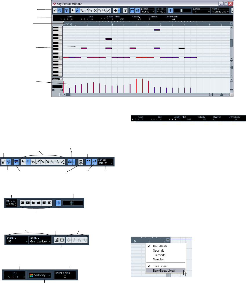
184
The MIDI editors
The Key Editor – Overview
The toolbar
As in other windows, the toolbar contains tools and vari-
ous settings. You can specify which toolbar items should
be shown and store/recall different toolbar configurations
– see “Using the Setup options” on page 262.
The info line
The info line shows information about selected MIDI
notes. You can edit all values on the info line using regular
value editing (see “Editing on the info line” on page 192
for details). Length and position values are displayed in
the format currently selected for the ruler (see below).
•To hide or show the info line, click the icon in the toolbar.
The ruler
The ruler shows the timeline, by default in the display format
selected on the Transport panel. You can select a separate
format for a MIDI editor ruler on the Ruler pop-up menu,
opened by clicking the arrow button to the right of it. For a
list of the available formats, see “The ruler” on page 21.
At the bottom of the pop-up menu, there are two additional
items:
Toolbar
Info line
Ruler
Note
display
Controller
display
Show/Hide
Info line
Solo Editor
button Key Editor
tools Autoscroll
Acoustic
Feedback Part list
Show/Hide Part
borders
Edit active
part only
Auto Select
Controllers
Nudge Tools Snap on/off
Velocity for inserted notes Grid modes
Quantize settings Step Input
MIDI Input
Step/MIDI input controls
Color pop-up menu
Chord recognition
display
Mouse pointer display: current
pitch and meter position
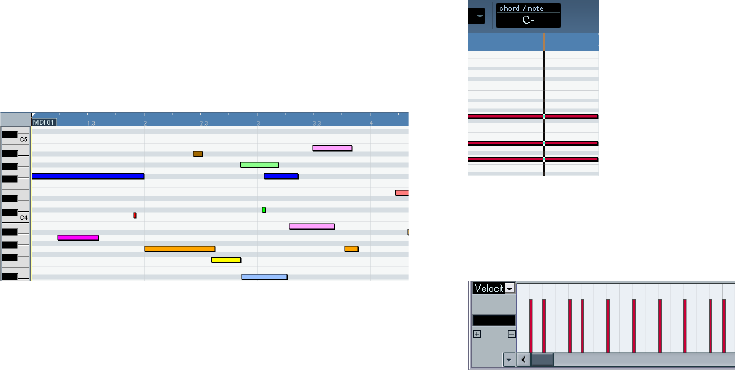
185
The MIDI editors
•If “Time Linear” is selected, the ruler, note display and
controller display will be linear in relation to time.
This means that if the ruler shows bars and beats, the distance between
the bar lines will vary depending on the tempo.
•If “Bars+Beats Linear” is selected, the ruler, note display
and controller display will be linear in relation to tempo.
This means that if the ruler shows bars and beats, the distance between
beats will be constant.
In most cases, you would probably set the display format
to “Bars+Beats” in “Bars+Beats Linear” mode when edit-
ing MIDI.
The note display
The note display is the main area in the Key Editor. It con-
tains a grid in which MIDI notes are shown as boxes. The
width of a box corresponds to the note length, and the
vertical position of a box corresponds to the note number
(pitch), with higher notes higher up in the grid. The piano
keyboard to the left serves as a guide for finding the right
note number.
For a description of how to display colors in the note dis-
play, see “Coloring notes and events” on page 188.
The chord recognition function
Cubase AI features a handy chord recognition function
that helps you identify chords in the Key Editor note dis-
play. To find out which chord is formed by simultaneously
played notes, place the project cursor over the notes. All
MIDI notes currently “touched” by the project cursor are
analyzed and the chord recognition display in the toolbar
shows you which chord the notes form.
In the picture above, the project cursor touches the notes C, Eb and G.
As shown in the chord recognition display, this results in a C minor chord.
The controller display
The area at the bottom of the Key Editor window is the
controller display. This consists of one or several control-
ler lanes, each showing one of the following properties or
event types:
• Velocity values of the notes
• Pitchbend events
• Aftertouch events
• Poly Pressure events
• Program Change events
• SysEx events
• Any type of continuous controller event (see “Editing conti-
nuous controllers on the controller lane” on page 197)
To change the size of the controller display, drag the di-
vider between the controller display and the note display.
This will make the controller display larger and the note
display smaller, or vice versa.
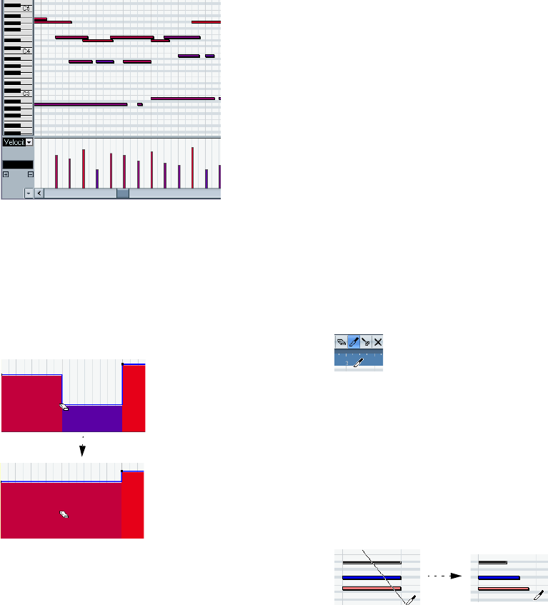
186
The MIDI editors
Velocity values are shown as vertical bars in the controller
display, with higher bars corresponding to higher velocity
values.
Each velocity bar corresponds to a note in the note display.
Events other than velocity values are shown as blocks, the
heights of which correspond to the values of the events.
The beginning of an event is marked by a curve point. To
select an event, click on the curve point, so that it turns red.
ÖUnlike notes, events in the controller display have no
length. The value of an event in the display is “valid” until
the start of the next event.
For a description of editing in the controller display, see
“Editing in the controller display” on page 193.
Key Editor operations
Zooming
Zooming in the Key Editor is done according to the stan-
dard zoom procedures, using the zoom sliders, the Zoom
tool or the Zoom submenu on the Edit menu.
•When you drag a rectangle with the Zoom tool, the result
depends on the option “Zoom Tool Standard Mode: Hori-
zontal Zooming Only” in the Preferences (Editing–Tools
page).
If this is activated, the window will only be zoomed horizontally; if not, the
window will be zoomed both horizontally and vertically.
Using the Trim tool
The Trim tool allows you to change the length of note
events by cutting off the end or the beginning of notes. It
is available in the Key Editor and in the List Editor.
Using the Trim tool means moving the note-on or the note-
off event for one or several notes to a position defined with
the mouse. Proceed as follows:
1. Select the Trim tool in the toolbar.
The mouse pointer changes to a knife symbol.
2. Locate the notes that you wish to edit.
3. To edit a single note, click on it with the Trim tool. The
range between the mouse pointer and the end of the note
will be removed.
You can use the mouse position display in the toolbar to find the exact
position for the trim operation.
4. To edit several notes, click and drag with the mouse
across the notes.
A line is displayed. The notes will be trimmed along this line.
Trimming the end of three note events.
•By default, the Trim tool will cut off the end of notes. To
trim the beginning of the note(s), press [Alt]/[Option] while
dragging.
If you delete the second event…
…the first event will be “valid”
until the start of the third event.
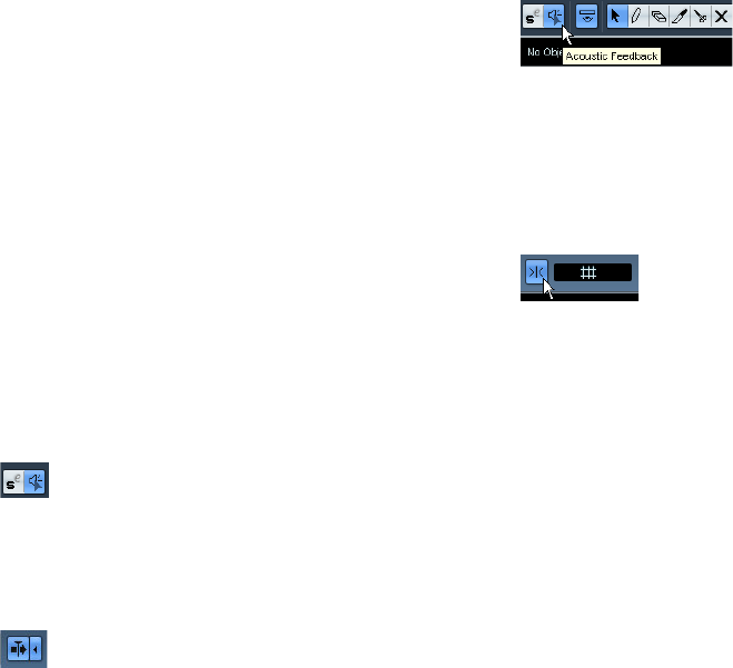
187
The MIDI editors
•If you press [Ctrl]/[Command] while dragging, you will
get a vertical trim line, allowing you to set the same start or
end time for all edited notes.
You can change the Trim tool key commands in the Prefe-
rences (Editing–Tool Modifiers page).
ÖNote that when you trim the beginning of a note in the
List Editor, the note may move to a different position in the
list (since other events may now begin before the edited
event).
ÖNote that the trimmed note ends or starts do not snap
to the grid.
Playing back
You can play back your music as usual when working in a
MIDI editor. There are several features designed to make
editing easier during playback:
Solo button
If you activate the Solo button, only the edited MIDI parts
will be heard during regular playback.
Autoscroll
As described in the section “Autoscroll” on page 41, the
Autoscroll function makes the window “follow” the project
cursor during playback, so that the current play position is
visible at all times. However, when you are working in a
MIDI editor, you may want to deactivate Autoscroll – this
way, the events you are working with will stay visible.
The Autoscroll buttons in each MIDI editor are independent
of the Project window Autoscroll setting, which means that
Autoscroll can be activated in the Project window and de-
activated in the MIDI editor you are working in.
Acoustic Feedback
If the speaker icon on the toolbar is activated, individual
notes will automatically be played back (auditioned) when
you move or transpose them, or when you create new notes
by drawing. This makes it easier to hear what you’re doing.
Snap
Snap is activated on the toolbar.
The Snap function helps you find exact positions when ed-
iting in a MIDI editor. It does this by restricting horizontal
movement and positioning to certain positions. Operations
affected by snap include moving, duplicating, drawing, siz-
ing, etc.
•How Snap works depends on the Snap mode pop-up
menu next to the Snap button.
See “The Snap function” on page 40.
•When the “Bars+Beats” display format is selected in
the ruler, the snap grid is set by the Quantize value on the
toolbar.
This makes it possible to snap not only to straight note values but also to
swing grids set up in the Quantize Setup dialog (see “The Quantizing
functions” on page 172).
When any of the other display formats is selected in the
ruler, positioning is restricted to the displayed grid, i.e. you
can snap in finer increments by zooming in, and in coarser
increments by zooming out the display.
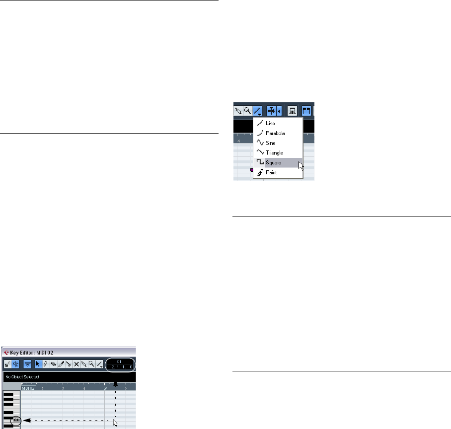
188
The MIDI editors
Coloring notes and events
By using the Colors pop-up menu on the toolbar, you can
select a color scheme for the events in the editor. The fol-
lowing options are available:
When any of the options (apart from “Part”) is selected,
you can select “Setup…” from the Colors pop-up menu.
This opens a dialog in which you can specify which colors
should be associated with which velocities, pitches or
channels, respectively.
Creating and editing notes
To draw in new notes in the Key Editor, you use the Pencil
tool or the Line tool.
Drawing notes with the Pencil tool
With the Pencil tool, you insert single notes by clicking at
the desired time (horizontal) and pitch position (vertical).
•When you move the pointer in the note display, its bar
position is indicated in the toolbar, and its pitch is indicated
both in the toolbar and on the piano keyboard to the left.
This makes it easy to find the right note and insert position.
•If Snap is activated, this determines the start position of
the created note.
•If you click once, the created note will have the length
set on the Length Quantize pop-up menu on the toolbar.
You can create a longer note by clicking and dragging. The length of the
created note will be a multiple of the Length Quantize value.
Drawing notes with the Line tool
The Line tool can be used for creating series of contigu-
ous notes. To do so, click and drag to draw a line and then
release the mouse button.
ÖThe Line tool has several different modes.
To select one of the modes, click on the Line tool icon on the toolbar
when the tool is already selected. This opens a pop-up menu from which
you can select one of the Line tool modes.
The tool icon will change appearance according to the se-
lected mode.
Option Description
Velocity The notes get different colors depending on their velocity
values.
Pitch The notes get different colors depending on their pitch.
Channel The notes get different colors depending on their MIDI
channel value.
Part The notes get the same color as their respective part in
the Project window. Use this option when you are work-
ing with two or more tracks in an editor, to make it easier
to see which notes belong to which track.
GridMatch The notes get different colors depending on their time
position. This mode makes it easy to see e.g. if the notes
in a chord start at the exact same beat.
Mode Description
Line This is the default mode for the Line tool. When this
mode is selected, you click and drag to create a straight
line, in any angle. When you release the mouse button a
series of notes will be created, aligned with the line. If
Snap is activated, the notes will be spaced and sized ac-
cording to the Quantize value.
Parabola, Sine,
Triangle,
Square
These modes insert events along different curve shapes.
While they can be used for creating notes, they are prob-
ably best suited for controller editing (see “Adding and
editing events in the controller display” on page 195).
Paint Allows you to insert multiple notes by dragging with the
mouse button pressed. If Snap is activated, the notes will
be positioned and sized according to the Quantize and
Length Quantize values. If you press [Ctrl]/[Command]
while painting, movement will be restricted to horizontal
(i.e. the painted notes will have the same pitch).
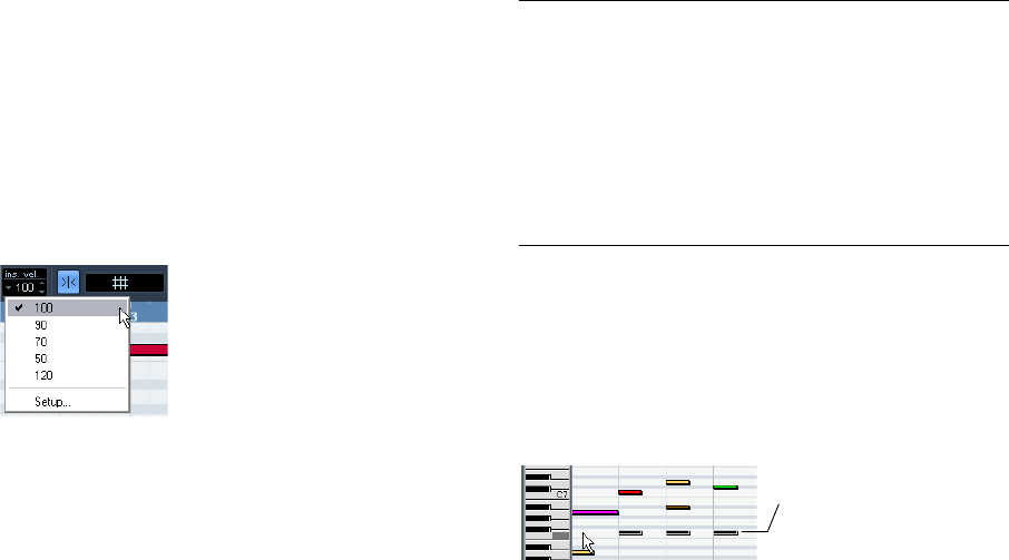
189
The MIDI editors
Setting velocity values
When you draw notes in the Key Editor, the notes will get
the velocity value set in the insert velocity field on the tool-
bar.
You can use one of four different methods for determining
the velocity:
•When a tool modifier is assigned for the Select tool–
Edit Velocity action (in the Editing–Tool Modifiers page of
the Preferences dialog), you can select one or more notes,
press the modifier (by default [Ctrl]/[Command]-[Shift])
and click on one of the selected notes to change the ve-
locity.
The cursor changes into a speaker and, next to the note, a field with the
velocity value appears – the Note Velocity slider. Move the mouse
pointer up or down to change the value. Value changes will be applied to
all selected notes, as you can see in the controller lane.
•Selecting a predefined velocity value from the insert ve-
locity pop-up menu.
The menu contains five different predefined velocity values. The “Setup…”
item opens a dialog that allows you to specify which five velocity values
should be available on the pop-up menu. (This dialog can also be opened
by selecting “Insert Velocities…” from the MIDI menu.)
•Manually entering the desired velocity value by clicking
in the insert velocity field and typing in the desired value.
•Using a key command.
You can assign a key command to each of the five available velocity val-
ues in the Key Commands dialog (MIDI category – the items Insert Ve-
locity 1–5). This allows for quick switching between different velocity
values when entering notes. See “Setting up key commands” on page
269 for instructions on how to set up key commands.
Selecting notes
Selecting notes is done using any of the following methods:
•Use the Arrow tool.
The standard selection techniques apply, like selecting by clicking on the
note or using a selection rectangle. Note that when you press [Shift] and
click on notes or draw a selection rectangle, these notes will be added to
the overall selection. When you press [Ctrl]/[Command] and click on
notes or draw a selection rectangle, these notes will be removed from
the overall selection (standard Windows behavior).
•Use the Select submenu on the Edit menu or context
menu.
The Select menu options are:
•You can also use the left and right arrow keys on the
computer keyboard to step from one note to another.
If you press [Shift] and use the arrow keys, the current selection will be
kept, allowing you to select several notes.
•To select all notes of a certain pitch, press [Ctrl]/[Com-
mand] and click on the desired key in the keyboard display
to the left.
You can also press [Shift] and double-click on a note to select all the fol-
lowing notes of the same pitch.
•If the option “Auto Select Events under Cursor” is acti-
vated in the Preferences (Editing page), all notes “touched”
by the project cursor are automatically selected.
Option Description
All Selects all notes in the edited part.
None Deselects all events.
In Loop Selects all notes that are partially or completely inside the
boundaries of the left and right locators (only visible if lo-
cators are set).
From Start
to Cursor Selects all notes that begin to the left of the project cur-
sor.
From Cursor
to End Selects all notes that end to the right of the project cur-
sor.
All notes of the corresponding
pitch are selected.
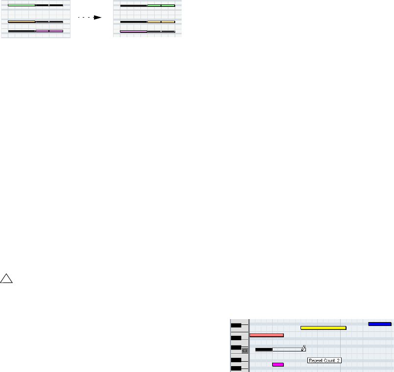
190
The MIDI editors
Toggle selections
If you want to toggle the selected elements within a selec-
tion rectangle, press [Ctrl]/[Command] and enclose the
same elements within a new selection rectangle. Once
you release the mouse button, the previous selection is
deselected and vice versa.
Selecting controllers within the note range
You can select the controllers within the range of the se-
lected notes. The following applies:
•When the Auto Select Controllers button is activated
on the toolbar, the controllers will always be selected
when the respective notes are selected.
•A note range lasts until the start of the next note or the
end of the part.
•Selected controllers for notes are moved when the cor-
responding notes are moved.
Moving and transposing notes
To move notes in the editor, use any of the following me-
thods:
•Click and drag to a new position.
All selected notes will be moved, maintaining their relative positions. If
Snap is activated, this determines to which positions you can move the
notes, see “Snap” on page 187.
•Use the up and down arrow keys on the computer key-
board.
This method allows you to transpose the selected notes, without risking
to move them horizontally. You can also use the Transpose function (see
“Transpose” on page 176) for this. Note that pressing [Shift] and using
the up and down arrow keys will transpose notes in steps of one octave.
•Use the Move to Cursor function on the Edit menu.
This moves the selected notes to the project cursor position.
•Select a note and adjust its position or pitch on the info
line.
See “Editing on the info line” on page 192.
•Use the Move buttons in the Nudge palette on the tool-
bar.
This moves the selected note(s) by the amount set on the Quantize pop-
up menu.
By default, the Nudge palette is not shown on the toolbar – see “Using
the Setup options” on page 262 for more information.
ÖNote that when you move selected notes to a different
position, any selected controllers for these notes will move
accordingly.
See also “Moving and copying events” on page 197.
You can also adjust the position of notes by quantizing
(see “The Quantizing functions” on page 172).
Duplicating and repeating notes
Notes are duplicated much in the same way as events in
the Project window:
•Hold down [Alt]/[Option] and drag the note(s) to a new
position.
If Snap is activated, this determines to which positions you can copy
notes (see “Snap” on page 187).
•Selecting Duplicate from the Edit menu creates a copy
of the selected note and places it directly after the original.
If several notes are selected, all of these are copied “as one unit”, main-
taining the relative distance between the notes.
•Selecting “Repeat…” from the Edit menu opens a dia-
log, allowing you to create a number of copies of the se-
lected note(s).
This works like the Duplicate function, but you can specify the number of
copies.
•You can also perform the Repeat function by dragging:
Select the note(s) to repeat, press [Alt]/[Option], click the
right edge of the last selected note and drag to the right.
The longer to the right you drag, the more copies are created (as indi-
cated by the tooltip).
!
Note also that you can restrict movement to horizon-
tal or vertical only by holding down [Ctrl]/[Command]
while dragging.
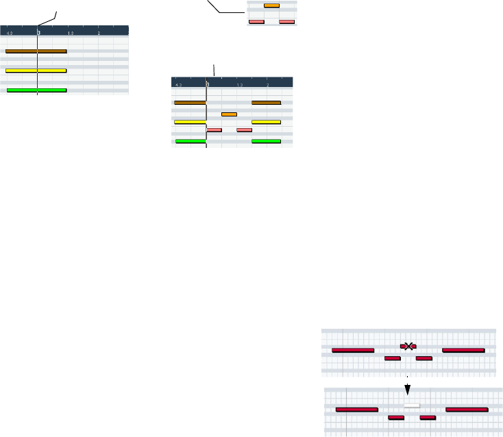
191
The MIDI editors
Using cut and paste
You can use the Cut, Copy and Paste options on the Edit
menu to move or copy material within a part or between
different parts. When you paste copied notes, you can ei-
ther use the regular Paste function or the function “Paste
Time” from the Range submenu of the Edit menu.
• “Paste” inserts the copied notes at the project cursor position
without affecting existing notes.
• “Paste Time” inserts at the project cursor position, but moves
(and if necessary, splits) existing notes to make room for the
pasted notes.
Resizing notes
To resize a note, use one of the following methods:
•Position the arrow tool at the start or end of the note, so
that the pointer takes on the shape of a small double ar-
row. Click and drag to the left or right to resize the note.
This method allows you to resize the note from either direction.
•Click with the Pencil tool within the note box and drag
to the left or the right (to make the note shorter or longer,
respectively).
With both these methods, the resulting length will be a
multiple of the Length Quantize value on the toolbar.
•Use the Trim Start/End buttons on the Nudge palette on
the toolbar.
This resizes the selected note(s) by moving their start or end positions, in
steps according to the Length Quantize value on the toolbar. By default,
the Nudge palette is not shown on the toolbar – see “Using the Setup op-
tions” on page 262 for more information.
•Select the note and adjust its length on the info line.
See “Editing on the info line” on page 192 for details on info line editing.
•Use the Trim tool, see “Using the Trim tool” on page 186.
Splitting notes
There are three ways to split notes:
•Clicking on a note with the Scissors tool splits the note
at the position you pointed (taking the Snap setting into
account if activated).
If several notes are selected, they are all split at the same position.
•If you select “Split at Cursor” from the Edit menu, all
notes that are intersected by the project cursor are split at
the cursor position.
•If you select “Split Loop” from the Edit menu, all notes
that are intersected by the left or right locator are split at
the locator positions.
Gluing notes
Clicking on a note with the Glue Tube tool will “glue it to-
gether” with the next note of the same pitch. The result will
be one long note spanning from the start of the first note
to the end of the second note and with the properties (ve-
locity, etc.) of the first note.
Muting notes
Individual notes can be muted in the Key Editor, as op-
posed to muting an entire MIDI part in the Project window.
This allows you to exclude notes from playback, but keep
the option to bring them back again at any time. To mute a
note, use one of the following methods:
•Click on it with the Mute tool.
•Drag a rectangle with the Mute tool, enclosing all notes
you want to mute.
•Select the note(s) and choose Mute from the Edit menu.
The default key command for this is [Shift]-[M].
Muted notes are “dimmed” in the note display.
To unmute a note, either click it or enclose it with the Mute
tool, or select it and choose Unmute from the Edit menu.
The default key command for this is [Shift]-[U].
Selecting “Paste Time” with this data on the clipboard
and the project cursor here…
…will give you this.
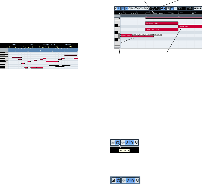
192
The MIDI editors
Deleting notes
To delete notes, either click on them with the Erase tool or
select them and press [Backspace].
Editing on the info line
The info line shows the values and properties of the se-
lected event(s). If a single event is selected, its values are
displayed on the info line. If several events are selected,
the info line shows the values of the first of these events in
yellow.
Several events are selected.
You can edit the values on the info line using regular value
editing. This allows you to move, resize, transpose or
change velocity of events in a very precise manner. It is
also possible to click the Pitch or Velocity field in the info
line and play a note on your MIDI keyboard – the pitch or
velocity will be adjusted according to the note you played.
ÖIf you have several events selected and change a value,
all selected events will be changed by the set amount.
ÖIf you have several events selected, hold down [Ctrl]/
[Command] and change a value, the change will be abso-
lute.
In other words, the value setting will be the same for all selected events.
How the Key Editor handles drum maps
When a drum map is assigned to a MIDI or instrument track
(see “Working with drum maps” on page 202), the Key Ed-
itor will display the drum sound names as defined by the
drum map.
In Cubase AI, the name of the drum sound is displayed in
the following locations:
This allows you to use the Key Editor for drum editing, e.g.
when editing drum note lengths (which may be necessary
for some external instruments) or when editing several
parts, to identify drum events.
Editing notes via MIDI
You can change the properties of notes via MIDI. For ex-
ample, this can be a fast way to get the right velocity value,
since you will hear the result even as you edit:
1. Select the note you want to edit.
2. Click on the MIDI Input button on the toolbar to enable
editing via MIDI.
3. Use the note buttons on the toolbar to decide which
properties should be changed by the MIDI input.
You can enable editing of pitch, note-on and/or note-off velocity.
With this setting, the edited notes will get the pitch and velocity values
of the notes input via MIDI, but the note-off velocities will be kept as
they are.
4. Play a note on your MIDI instrument.
The note selected in the editor will get the pitch, velocity and/or note-off
velocity of the played note.
The next note in the edited part is automatically selected,
making it easy to quickly edit a series of notes.
In the info line, in the Pitch field. In the Mouse Note Value field.
In the event itself (provided that the
zoom factor is high enough).
When dragging a note.
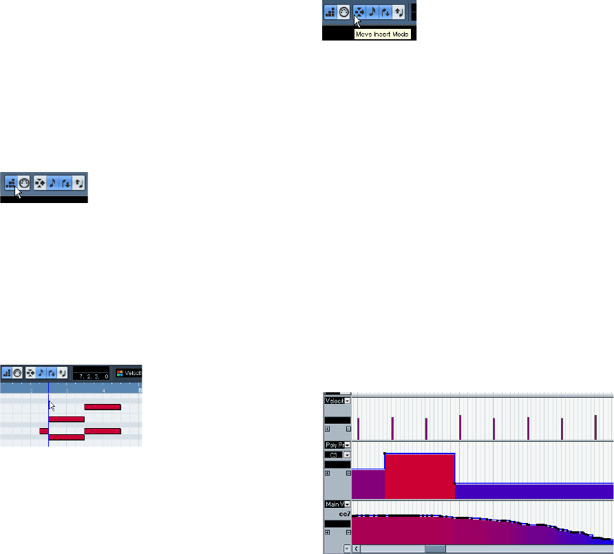
193
The MIDI editors
•If you want another try, select the note again (e.g. by
pressing the left arrow key on the computer keyboard) and
again play a note on your MIDI instrument.
Step input
Step input, or step recording, is when you enter notes one
at a time (or one chord at a time) without worrying about
the exact timing. This is useful e.g. when you know the part
you want to record but are not able to play it exactly as you
want it.
Proceed as follows:
1. Click the Step Input button on the toolbar to activate
Step Input mode.
2. Use the note buttons to the right to decide which
properties should be included when you input the notes.
For example, you may not want to include the velocity and/or note-off ve-
locity of the played notes. It is also possible to turn off the pitch property,
in which case all notes will get the pitch C3, no matter what you play.
3. Click anywhere in the note display to set the start po-
sition (the desired position of the first note or chord).
The step input position is shown as a blue line in the note display, and in
the lower mouse pointer display in the toolbar.
4. Specify the desired note spacing and length with the
Quantize and Length Quantize pop-up menus.
The notes you input will be positioned according to the Quantize value
and have the length set with the Length Quantize value. For instance, if
you set Quantize to 1/8 notes and Length Quantize to 1/16 note, the
notes will be sixteenth notes, appearing on each eighth note position.
5. Play the first note or chord on your MIDI instrument.
The note or chord appears in the editor and the step input position ad-
vances one quantize value step.
ÖIf Move Insert Mode is activated, all notes to the right
of the step input position will be moved to “make room” for
the inserted note or chord.
Move Insert Mode is activated.
6. Continue in the same way with the rest of the notes or
chords.
You can adjust the Quantize or Length Quantize value as you go along,
to change the timing or note lengths. You can also move the step input
position manually by clicking anywhere in the note display.
•To insert a “rest”, press the right arrow key on the com-
puter keyboard.
This advances the step input position one step.
7. When you are done, click the Step Input button again
to deactivate step input.
Editing in the controller display
About controller lanes
By default, the controller display has a single lane, show-
ing one event type at a time. However, you can add lanes
by clicking the plus button or by opening the context menu
and selecting “Create New Controller Lane”. The use of
several controller lanes allows you to view and edit differ-
ent controllers at the same time.
The controller display with three lanes set up
•To remove a lane, click on the minus sign or open the
context menu and select “Remove this Lane”.
This hides the lane from view – it does not affect the events in any way.
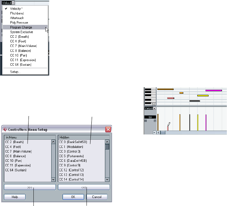
194
The MIDI editors
•If you remove all lanes, the controller display will be
completely hidden.
To bring it back again, select “Create New Controller Lane” from the
context menu.
•Editing the events in the controller display is much like
editing automation data on an automation track in the Pro-
ject window (except for velocity values, see “Editing velo-
city values” on page 194).
Selecting the event type
Each controller lane shows one event type at a time. To
select which type should be displayed, use the event type
pop-up menu to the left of the lane.
•Selecting “Setup…” opens a dialog in which you can
specify which continuous controller event types should be
available on the pop-up menu.
•Each MIDI track has its own controller lane setup (num-
ber of lanes and selected event types).
When you create new tracks, they get the controller lane setup used last.
Controller lane presets
Once you have added the required number of controller
lanes and selected the event types you need, you can
store this combination as a controller lane preset. You
could for example have a preset with one velocity lane
only, another with a combination of velocity, pitchbend
and modulation, and so on. This can make working with
controllers much quicker.
•To add the current controller lane setup as a preset, pull
down the pop-up menu to the left of the horizontal scroll-
bar and select “Add”.
Enter a name for the preset in the dialog that appears and click OK.
•To apply a stored preset, select it from the pop-up menu.
This immediately brings up the controller lanes and event types in the
preset.
•To remove or rename presets, select “Organize…” from
the pop-up menu.
Editing velocity values
When “Velocity” is selected, the lane shows the velocity of
each note as a vertical bar.
Velocity values are edited with the Pencil or the Line tool.
The different tools and Line tool modes offer several pos-
sibilities, as listed below:
ÖThe Arrow tool automatically switches to the Pencil tool
when you move the pointer into the controller display.
If you want to use the Arrow tool to select events in the controller display,
press [Alt]/[Option].
ÖIf the Speaker icon (Acoustic Feedback) is activated
on the toolbar, the notes will be played back when you ad-
just the velocity, allowing you to audition your changes.
Controller types in this list are
already listed on the pop-up
menu.
Controller types in this list are
not listed on the pop-up menu.
Click this button to add the
selected controller type to the
pop-up menu.
Click this button to remove the
controller type selected in the left
list from the pop-up menu.
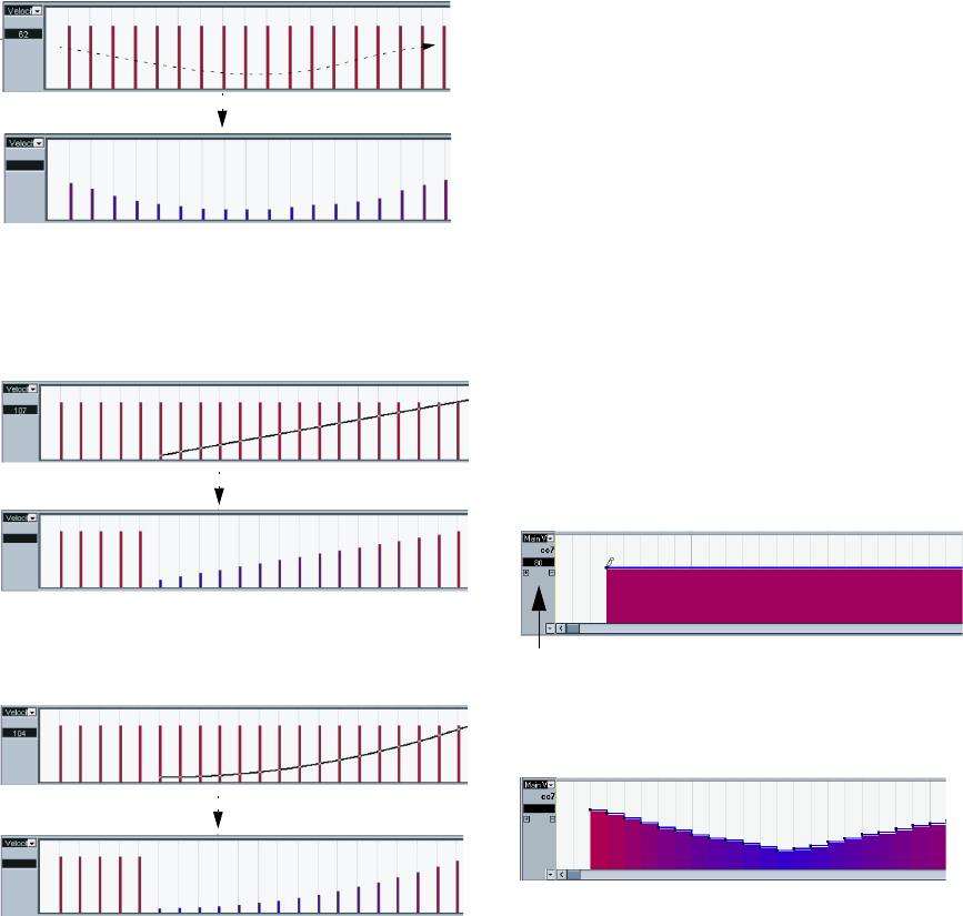
195
The MIDI editors
•You can use the Pencil tool to change the velocity of a
single note: click on its velocity bar and drag the bar up or
down.
While you drag, the current velocity value is shown in the display to the left.
•You can use the Pencil tool or the Line tool in Paint
mode to change the velocity values of several notes by
painting a “freehand curve”.
When editing velocity, these two methods have the same functionality.
•Use the Line tool in Line mode for creating linear veloc-
ity ramps.
Click where you want the ramp to start and drag the cursor to where you
want the ramp to end. When you release the mouse button, the velocity
values are aligned with the line between the two points.
•Parabola mode works in the same way, but aligns the
velocity values to a Parabola curve instead.
Use this for smooth, “natural” velocity fades, etc.
•The remaining three Line tool modes (Sine, Triangle and
Square) align the velocity values to continuous curve
shapes (see below).
ÖIf there is more than one note at the same position
(e.g. a chord), their velocity bars will overlap in the control-
ler lane.
If none of the notes are selected, all notes at the same position will be set
to the same velocity value when you draw. To edit the velocity of only one
of the notes at the same position, first select the note in the note display.
Now, editing will only affect the velocity of the selected note.
You can also adjust the velocity of a single note by select-
ing it and changing its velocity value on the info line.
Adding and editing events in the controller display
When any option other than “Velocity” is selected for a
controller lane, you can create new events or edit the val-
ues of existing events using the Pencil tool or the Line tool
in its various modes:
•Click with the Pencil tool or the Line tool in Paint mode
to create a new event.
•Press [Alt]/[Option] and use the Pencil tool or the Line
tool in Paint mode to modify the value of an event (without
creating a new one).
Note that you can click and drag to change or add multiple events, draw
controller curves, etc. You can press or release [Alt]/[Option] while draw-
ing, switching dynamically between “edit mode” and “create mode”.
If you want to enter or adjust a single event, click once
with the Pencil tool or the Line tool in Paint mode.
If you want to “paint a curve”, drag with the tool in the con-
troller lane (keeping the mouse button pressed):
When you move the pointer in the controller lane, the corresponding
value is displayed in this field.
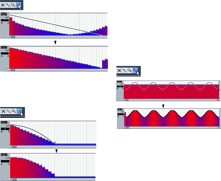
196
The MIDI editors
ÖWith the Pencil tool and the Line tool in Paint mode, the
quantize value determines the “density” of created control-
ler curves (if Snap is activated, see “Snap” on page 187).
For very smooth curves, you should use a small quantize value or turn off
Snap. However, this will create a very large number of MIDI events, which
can cause MIDI playback to “stutter” in some situations. A medium-low
density is often sufficient.
•Clicking and dragging with the Line tool in Line mode
shows a line in the controller lane, and creates events with
values aligned to this line.
This is the best way to draw linear controller ramps. If you press [Alt]/[Op-
tion], no new events are created – use this mode for modifying existing
controller curves.
•The Parabola mode works in the same way, but aligns
the values to a parabola curve instead, giving more “natu-
ral” curves and fades.
Note that the result depends on the direction from which you draw the
parabola.
•In Parabola mode, you can use modifier keys to deter-
mine the shape of the parabola curve.
If you press [Ctrl]/[Command], the parabola curve will be reversed. If you
press [Alt]/[Option]-[Ctrl]/[Command] while Snap is activated, you can
change the position of the whole curve (in both cases the snap value for
the positioning will be a quarter of the quantize value). If you press [Shift],
the exponent will be increased or decreased.
ÖIn Line and Parabola modes, the length quantize value
determines the “density” of created controller curves (if
Snap is activated).
For very smooth curves, you should use a small length quantize value or
turn off Snap. To avoid over-dense controller curves (which may cause
MIDI playback to “stutter”), use a medium-low density.
•The Sine, Triangle and Square modes create events
with values aligned to continuous curves.
In these modes, the quantize value determines the period of the curve
(the length of one curve “cycle”) and the length quantize value deter-
mines the density of the events (the lower the length quantize note value,
the smoother the curve).
•In Sine, Triangle and Square mode you can also use
modifier keys to determine the shape of the curve.
If you press [Ctrl]/[Command] you can change the phase of the beginning
of the curve, if you press [Alt]/[Option]-[Ctrl]/[Command] while snap is ac-
tivated you can change the position of the whole curve (in both cases the
snap value for the positioning will be a quarter of the quantize value).
ÖYou can also set the curve period freely by holding
down [Shift] when you insert events in Sine, Triangle or
Square mode.
Activate Snap, [Shift]-click and drag to set the length of one period. The
period length will be a multiple of the quantize value.
•In Triangle and Square mode, you can press [Shift]-
[Ctrl]/[Command] to change the maximum position of the
triangle curve (to create sawtooth curves) or the pulse of
the square curve. As in other modes, you can press [Alt]/
Converting a controller curve to a ramp using the
Line tool.
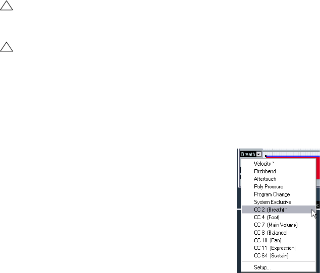
197
The MIDI editors
[Option] if you want to change the existing events rather
than creating new ones. Again, the snap value for the po-
sitioning will be a quarter of the quantize value.
Moving and copying events
You can move or duplicate events in a controller lane,
much like you can with notes:
1. Click with the Arrow tool to select the events you want
to cut or copy.
You can also click and drag to create a selection rectangle encompass-
ing the desired events.
2. Click on a curve point and drag the events to move
them.
If Snap is activated, this determines to which positions you can move the
events (see “Snap” on page 187).
Using cut, copy and paste
You can use the standard Cut, Copy and Paste options on
the Edit menu to move or copy events in the controller dis-
play:
1. Select the events you want to cut or copy.
2. Select Cut or Copy from the Edit menu.
3. If you want to paste the events into another MIDI part,
open that part in another Key Editor window.
4. Position the project cursor where you want to paste
the events.
5. Select Paste from the Edit menu.
The events on the clipboard are added, starting at the project cursor po-
sition, maintaining their relative distances. If a pasted event ends up at
the same position as an existing event of the same type, the old event is
replaced.
Deleting events in the controller display
You delete events by clicking on them with the Erase tool
or by selecting them and pressing [Backspace]. Please
note:
•Deleting a controller event makes the last event before
this valid up until the next event. It does not “zero” any
controller changes.
•You can delete notes by deleting their velocity bars in
the controller display.
Please be aware that if there is more than one note on the same position,
there may still only be one velocity bar visible – make sure you delete only
the desired notes!
Editing continuous controllers on the controller lane
When a continuous controller is selected for a controller
lane, additional data is displayed on the controller lane.
This is due to the fact that MIDI controller data can be re-
corded (or entered) either for an automation track or for a
MIDI part.
The following applies:
•In the event type pop-up menu, an asterisk is displayed
next to the controller name if automation data already ex-
ists for this controller.
This can be either controller data you entered in a MIDI editor (the data
will then be displayed on the controller lane), or controller data recorded
on an automation track in the Project window (in which case no events
are displayed on the controller lane).
For this controller, automation data is available.
•On the controller lane, you can also see the controller
curve that is applied before the part starts. That way, you
know which controller value (if any) is currently being used
at the starting point of the part so that you can choose the
start value accordingly.
!
Remember that a non-note event does not have a
length – it is “valid” until the next event (see “The
controller display” on page 185).
!
When the Auto Select Controllers button is activated
in the Key Editor toolbar, selecting notes will also se-
lect the corresponding controller events. Moving
events (either using cut/copy/paste or drag & drop)
in the note display will also move the corresponding
controller events (see also “Selecting controllers
within the note range” on page 190).
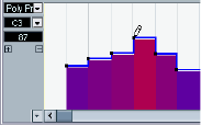
198
The MIDI editors
Adding and editing Poly Pressure events
Poly Pressure events are special, in that they “belong to” a
specific note number (key). That is, each Poly Pressure
event has two editable values: the note number and the
amount of pressure. Therefore, when Poly Pressure is se-
lected on the event type pop-up menu, there are two value
fields to the left of the controller display, one for the note
number and one for the amount.
To add a new Poly Pressure event, proceed as follows:
1. Select Poly Pressure on the event type pop-up menu.
2. Set the note number by clicking on the keyboard dis-
play.
The selected note number is displayed in the upper value field to the left
of the controller display. Note that this only works for the topmost lane. If
you have selected “Poly Pressure” for several controller lanes, you have
to type in the desired note number directly in the lower value field to the
left of each lane.
3. Use the Pencil tool to add a new event, just as when
adding regular controller events.
To view and edit existing Poly Pressure events, proceed
as follows:
1. Select Poly Pressure on the event type pop-up menu.
2. Click on the arrow button next to the note number field
to the left of the controller lane.
A pop-up menu appears, listing all note numbers for which there already
are Poly Pressure events.
3. Select a note number from the pop-up menu.
The Poly Pressure events for the selected note number are shown in the
controller lane.
4. Use the Pencil tool to edit the events as usual.
Press [Alt]/[Option] to edit existing events without adding any new ones.
•Poly Pressure events can also be added and edited in
the List Editor.
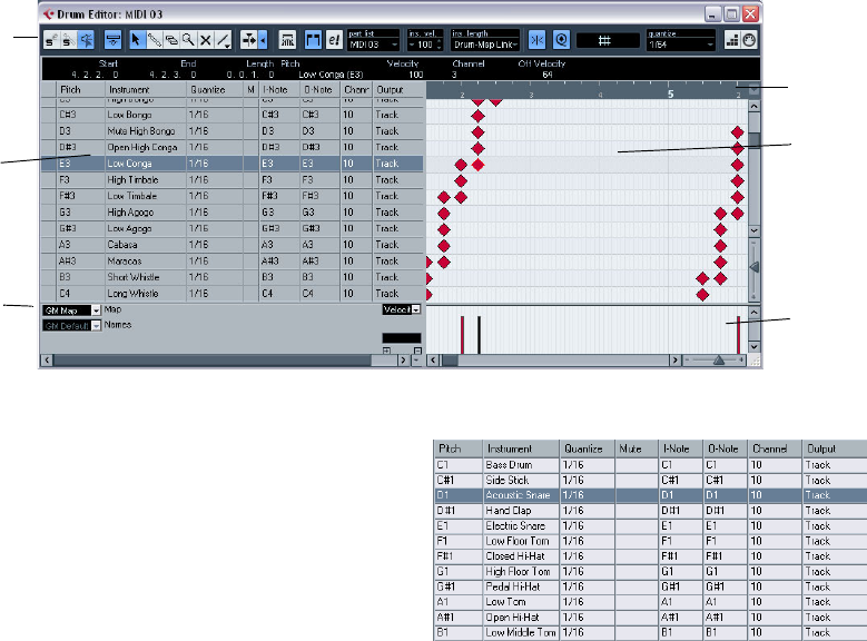
199
The MIDI editors
The Drum Editor – Overview
The toolbar and info line
These are much the same as the toolbar and info line in
the Key Editor (see “The Key Editor – Overview” on page
184), with the following differences:
•The Drum Editor has no Pencil tool – instead there is a
Drumstick tool (for entering and removing notes) and a
Line tool with various line and curve modes (for drawing
several notes in one go or editing controller events).
•There are no Scissors and Glue Tube tools in the Drum
Editor.
•As in the Key Editor, the mouse pointer display in the
toolbar shows the pitch and position of the pointer, but the
pitch is shown as a drum sound name rather than a note
number.
•The Use Global Quantize button allows you to select
which value should be used when Snap is activated – the
global quantize value on the toolbar or the individual quan-
tize values for the drum sounds.
•Instead of a Length Quantize pop-up, there is an Insert
Length pop-up menu.
It is used in much the same way, as described on the following pages.
The drum sound list
A drum sound list for GM Drum Map
The purpose of the Drum Editor is to edit MIDI tracks where
each note (pitch) plays a separate sound, as is typically the
case with a MIDI drum kit. The drum sound list to the left
lists all drum sounds by name (according to the selected
drum map or name list – see below), and lets you adjust
and manipulate the drum sound setup in various ways.
Please note the following:
•The number of columns in the list depends on whether a
drum map is selected for the track or not.
See “Working with drum maps” on page 202.
•You can reorder the columns by dragging the column
headings, and resize them by dragging the dividers be-
tween the column headings.
Toolbar
Ruler
Note
display
Controller
display
Drum
sound
list
Drum
Maps
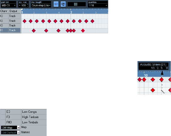
200
The MIDI editors
The note display
The note display of the Drum Editor displays notes as dia-
mond symbols. The vertical position of the notes corres-
ponds to the drum sound list to the left, while the horizontal
position corresponds to the note’s position in time, just as in
the Key Editor. Note, however, that the diamond symbols do
not indicate the length of the notes. This makes sense,
since drum sounds most often are “one-shot” samples that
play to their end regardless of the note lengths.
Drum map and name pop-up menus
Below the drum sound list you will find two pop-up menus,
used for selecting a drum map for the edited track or (if no
drum map is selected) a list of drum sound names. For an
explanation of drum maps, see “Working with drum maps”
on page 202.
Controller display
The controller display in the Drum Editor is the same as in
the Key Editor. You can add or remove controller lanes via
the context menu, and create and edit events as described
in the section “Editing in the controller display” on page
193.
•Note that when you select a line in the drum sound list
(to the left of the event display), only the velocity controller
events belonging to the note events on this line are dis-
played in the controller display.
•You can select more than one line in the drum sound list
(using [Shift] or [Ctrl]/[Command] as usual), which will
show all velocity controller events for all notes on all se-
lected lines.
This will help you when having to adjust the controller values between
different drum sounds.
Drum Editor operations
The basic handling (zooming, playback, auditioning, etc.)
is the same as in the Key Editor (see “Key Editor opera-
tions” on page 186). The following sections describe the
procedures and features specific to the Drum Editor.
Creating and editing notes
The standard way of entering notes in the Drum Editor is
to click with the Drumstick tool.
When you move the pointer in the note display, its bar position and
drum sound is indicated in the toolbar, making it easy to find the right
sound and position.
The position of the created note depends on the following
factors:
•If Snap is deactivated on the toolbar, the note will ap-
pear exactly where you clicked.
In this mode, notes can be positioned freely.
•If Snap is activated and Use Global Quantize is deacti-
vated on the toolbar, the note will snap to positions ac-
cording to the quantize value set for the sound in the drum
sound list.
You can set up different quantize values for different drum sounds. You
may for example want hi-hat notes snap to sixteenth notes, but snare and
bass drum snap to eighth notes.
•If Snap and Use Global Quantize are activated, the note
will snap to positions according to the Quantize setting on
the toolbar (next to the Use Global Quantize button).
The length of the inserted note is determined by the Insert
Length setting on the toolbar. However, if this is set to
“Drum-Map Link”, the note will get the length of the quan-
tize value for the drum sound.
ÖYou can quickly audition the drum sounds by clicking
in the leftmost column in the drum sound list.
This plays the corresponding note.
ÖClicking with the Drumstick tool on an existing note
will remove it.
This makes drum pattern editing very quick and intuitive.
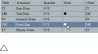
201
The MIDI editors
Setting velocity values
The notes you enter will get the insert velocity value set in
the insert velocity field on the toolbar – to speed up things
you may want to assign key commands to the insert velo-
city options, see “Setting velocity values” on page 189.
Selecting notes
Selecting notes is done by any of the following methods:
•Use the Arrow tool.
The standard selection techniques apply.
•Use the Select submenu on the context menu (see
“Selecting notes” on page 189).
•Use the left and right arrow keys on the computer key-
board to step from one note to the next or previous note.
If you press [Shift] and use the arrow keys, the current selection will be
kept, allowing you to select several notes.
•You can also press [Shift] and double-click on a note to
select all the following notes for the same drum sound.
•If the option “Auto Select Events under Cursor” is acti-
vated in the Preferences (Editing page), all notes currently
“touched” by the project cursor are automatically selected.
Moving, duplicating or repeating notes
To move or copy notes in the editor (to other positions or
other drum sounds), you use the same methods as in the
Key Editor: click and drag, use the arrow keys or Edit
menu functions, etc. – see “Moving and transposing no-
tes” on page 190. To help you identify the right notes, the
drum sound names as defined in the drum map are dis-
played in the Pitch field on the Drum Editor info line and,
when dragging notes in the event display, in the text fields
displayed next to the mouse pointer.
There is one other thing to note:
When you move or copy several selected notes by drag-
ging them and Snap is activated but Use Global Quantize
is deactivated, the notes will snap to positions according
to the quantize values for the drum sounds. If the moved/
copied notes have different quantize values, the largest
value will determine snapping. For example, if you are
moving two notes, with the quantize values 1/16 and 1/4
respectively, the notes will snap to quarter notes (1/4).
ÖYou can also adjust the position of notes by quantizing
(see “The Quantizing functions” on page 172).
Again, which quantize value is used depends on whether Global Quan-
tize is used.
Muting notes and drum sounds
You can mute individual notes by clicking or enclosing
them with the Mute tool or by using the Mute function on
the Edit menu (see “Muting notes” on page 191).
Furthermore, if a drum map is selected (see “Selecting a
drum map for a track” on page 204), the drum sound list will
have a Mute column. Click in the Mute column for a drum
sound to mute that sound. Clicking the Drum Solo button
will mute all drum sounds other than the selected one.
Muted drum sounds
Deleting notes
To delete notes, click on them with the Drumstick or Erase
tool, or select them and press [Backspace].
Other editing methods
As in the Key Editor, you can edit notes on the info line or
via MIDI, and enter notes using step input, see “Editing on
the info line” on page 192.
!
Please note that the mute state for drum sounds is
part of the drum map, so any other tracks using the
same map will also be affected.
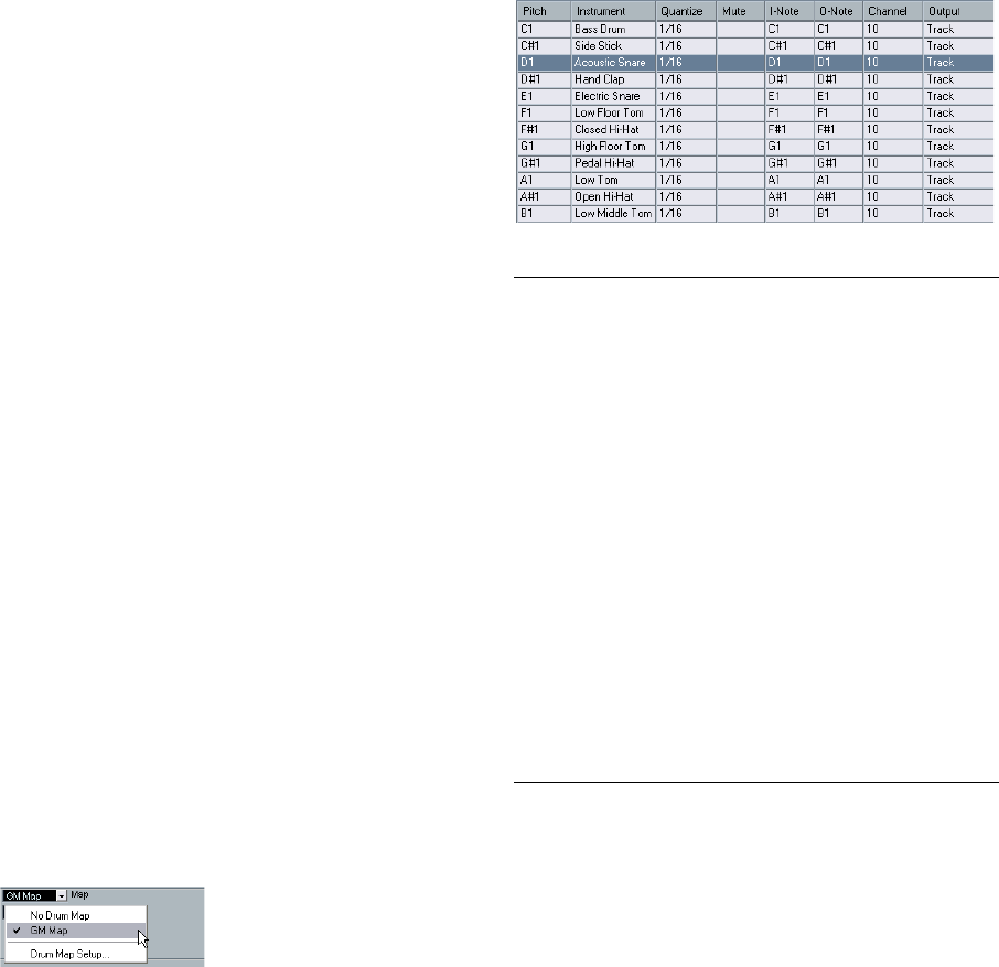
202
The MIDI editors
Working with drum maps
Background
A drum kit in a MIDI instrument is most often a set of dif-
ferent drum sounds with each sound placed on a separate
key (i.e. the different sounds are assigned to different MIDI
note numbers). One key plays a bass drum sound, another
a snare and so on.
Unfortunately, different MIDI instruments often use differ-
ent key assignments. This can be troublesome if you have
made a drum pattern using one MIDI device, and then
want to try it on another. When you switch the device, it is
very likely that your snare drum becomes a ride cymbal, or
your hi-hat becomes a tom, etc. – just because the drum
sounds are distributed differently in the two instruments.
To solve this problem, and simplify several aspects of MIDI
drum kits (like using drum sounds from different instru-
ments in the same “drum kit”), Cubase AI features so-
called drum maps. A drum map is a list of drum sounds,
with a number of settings for each sound. When you play
back a MIDI track for which you have selected a drum
map, the MIDI notes are “filtered” through the drum map
before being sent to the MIDI instrument. Among other
things, the map determines which MIDI note number is
sent out for each drum sound, and so which sound is
played in the receiving MIDI device.
A solution to the problem above would therefore be to set
up drum maps for all your instruments. When you want to
try your drum pattern on another instrument, you simply
switch to the corresponding drum map and your snare
drum sound will remain a snare drum sound.
Drum map settings
A drum map consists of settings for 128 drum sounds
(one for each MIDI note number). To get an overview of
these settings, open the Drum Editor and use the Map
pop-up menu below the drum sound list to select the “GM
Map” drum map.
This drum map is set up according to the General MIDI standard. For in-
formation on how to load, create and select other drum maps, see
“Managing drum maps” on page 204.
Now, take a look at the drum sound list (you may have to
drag the divider between the list and the note display to
the right to see all columns). The columns show the set-
tings of the drum map for each sound.
Here’s a brief description (details follow below):
ÖAll settings in a drum map (except the pitch) can be
changed directly in the drum sound list or in the Drum
Map Setup dialog (see “The Drum Map Setup dialog” on
page 204).
Note that the changes you make will affect all tracks that use the drum
map.
Column Description
Pitch The actual note number of the drum sound. This is what
links notes on a MIDI track to drum sounds. For example,
with the above drum map, all MIDI notes with the pitch
C1 would be mapped to the Bass Drum sound.
Instrument The name of the drum sound.
Quantize This value is used when entering and editing notes as de-
scribed in the sections “Creating and editing notes” on
page 200 and “Moving, duplicating or repeating notes”
on page 201.
Mute Allows you to mute a drum sound, excluding it from play-
back, see “Muting notes and drum sounds” on page 201.
I-note This is the “input note” for the drum sound. When this
MIDI note is sent into Cubase AI, (i.e. played by you), the
note will be mapped to the corresponding drum sound
(and automatically transposed according to the Pitch set-
ting for the sound).
O-note This is the “output note”, i.e. the MIDI note number that is
sent out every time the drum sound is played back.
Channel The drum sound will be played back on this MIDI channel.
Output The drum sound will be played back on this MIDI output.
If you set this to “Default”, the MIDI output selected for
the track will be used.
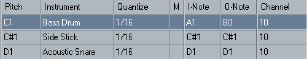
203
The MIDI editors
About Pitch, I-note and O-note
This can be a somewhat confusing area, but once you
have grasped how it all works it is not very complicated.
Going through the following “theory” will help you make
the most out of the drum map concept – especially if you
want to create your own drum maps.
As mentioned earlier, a drum map is a kind of “filter”,
transforming notes according to the settings in the map. It
does this transformation twice; once when it receives an
incoming note (i.e. when you play a note on your MIDI
controller) and once when a note is sent from the program
to the MIDI sound device.
In the following example, we have modified the drum map,
so that the Bass Drum sound has different Pitch, I-note
and O-note values.
I-notes (input notes)
Let’s look at what happens on input: When you play a note
on your MIDI instrument, the program will look for this note
number among the I-notes in the drum map. If you play the
note A1, the program will find that this is the I-note of the
Bass Drum sound.
This is where the first transformation happens: the note
will get a new note number according to the Pitch setting
for the drum sound. In our case, the note will be trans-
formed to a C1 note, because that is the pitch of the Bass
Drum sound. If you record the note, it will be recorded as a
C1 note.
O-notes (output notes)
The next step is the output. This is what happens when you
play back the recorded note, or when the note you play is
sent back out to a MIDI instrument in realtime (MIDI Thru):
The program checks the drum map and finds the drum
sound with the pitch of the note. In our case, this is a C1
note and the drum sound is the Bass Drum. Before the
note is sent to the MIDI output, the second transformation
takes place: the note number is changed to that of the O-
note for the sound. In our example, the note sent to the
MIDI instrument will be a B0 note.
Usage
Again, the purposes are different for I-notes and O-notes:
ÖChanging the I-note settings allows you to choose
which keys will play which drum sounds, when playing or
recording from a MIDI instrument.
For example, you may want to place some drum sounds near each other
on the keyboard so that they can be easily played together, move sounds
so that the most important sounds can be played from a short keyboard,
play a sound from a black key instead of a white, and so on.
If you never play your drum parts from a MIDI controller (but draw them in
the editor) you need not care about the I-note setting.
ÖThe O-note settings let you set things up so that the
“Bass Drum” sound really plays a bass drum.
If you are using a MIDI instrument in which the bass drum sound is on the
C2 key, you set the O-note for the Bass Drum sound to C2. When you
switch to another instrument (in which the bass drum is on C1) you want
the Bass Drum O-note set to C1. Once you have set up drum maps for
all your MIDI instruments, you need not care about this anymore – you
just select another drum map when you want to use another MIDI instru-
ment for drum sounds.
The channel and output settings
You can set separate MIDI channels and/or MIDI outputs
for each sound in a drum map. The following rules apply:
•When a drum map is selected for a track, the MIDI
channel settings in the drum map override the MIDI chan-
nel setting for the track.
In other words, the MIDI channel setting you make in the Track list or In-
spector for the track is normally disregarded. If you want a drum sound to
use the channel of the track, set it to channel “Any” in the drum map.
•If the MIDI output is set to “default” for a sound in a
drum map, the sound will use the MIDI output selected for
the track.
Selecting any other option allows you to direct the sound to a specific
MIDI output.
By making specific MIDI channel and output settings for
all sounds in a drum map, you can direct your drum tracks
directly to another MIDI instrument simply by selecting an-
other drum map – you need not make any channel or out-
put changes for the actual track.
ÖTo select the same MIDI channel for all sounds in a
drum map, click in the Channel column, press [Ctrl]/
[Command] and select the desired channel.
All drum sounds will be set to this MIDI channel. The same procedure
can be used for selecting the same MIDI output for all sounds as well.
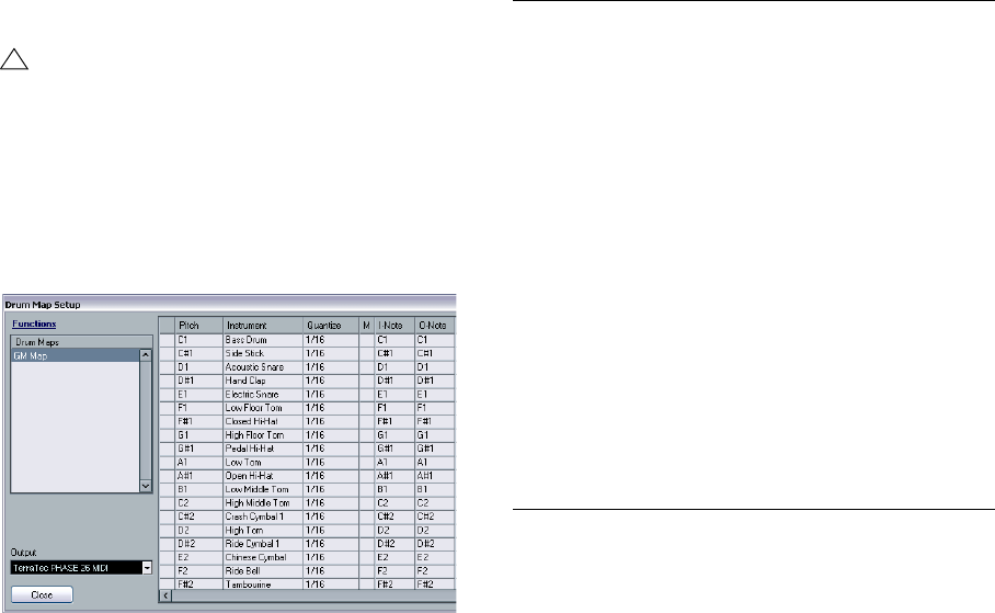
204
The MIDI editors
It can also be useful to select different channels and/or out-
puts for different sounds. This allows you to construct drum
kits with sounds from several different MIDI devices, etc.
Managing drum maps
Selecting a drum map for a track
To select a drum map for a MIDI track, use the Map pop-
up menu in the Inspector or in the Drum Editor.
Selecting “No Drum Map” turns off the drum map func-
tionality in the Drum Editor. Even if you do not use a drum
map, you can still separate sounds by name using a name
list (see “Using drum name lists” on page 205).
The Drum Map Setup dialog
To set up and manage your drum maps, select Drum Map
Setup from the Map pop-up menu or the MIDI menu. This
opens the following dialog:
The Drum Map Setup dialog
This is where you load, create, modify and save drum
maps. The list to the left shows the currently loaded drum
maps; selecting a drum map in the list displays its sounds
and settings to the right.
ÖThe settings for the drum sounds are exactly the same
as in the Drum Editor (see “Drum map settings” on page
202).
As in the Drum Editor, you can click the leftmost column to audition a
drum sound. Note: if you audition a sound in the Drum Map Setup dialog,
and the sound is set to MIDI output “Default”, the output selected on the
Output pop-up menu in the lower left corner will be used. When audi-
tioning a Default output sound in the Drum Editor, the MIDI output se-
lected for the track will be used, as described in section “The channel
and output settings” on page 203.
Open the Functions pop-up menu in the top left corner to
open a list of available functionalities:
ÖDrum maps are saved with the project files. If you have
created or modified a drum map, you should use the Save
function to store it as a separate XML file, available for
loading into other projects.
If you always want to have the same drum map(s) included in your projects,
you may want to load these into the template – see “Save as Template” on
page 256.
!
Initially, the Map pop-up menu will only contain one
map: “GM Map”. However, you will find a number of
drum maps included on the program DVD – how to
load these is described below.
Button Description
New Map Click this to add a new drum map to the project. The
drum sounds will be named “Sound 1, Sound 2” and so
on, and have all parameters set to default values. The
map will be named “Empty Map”, but you can rename it
by clicking and typing in the list.
New Copy Adds a copy of the currently selected drum map. This is
probably the quickest way to create a new drum map: se-
lect the map that is similar to what you want, create a
copy, change the desired drum sound settings and re-
name the map in the list.
Remove Removes the selected drum map from the project.
Load Opens a file dialog, allowing you to load drum maps from
disk. On the Cubase AI DVD you will find a number of
drum maps for different MIDI instruments – use this func-
tion to load the desired maps into your project.
Save Opens a file dialog for saving the drum map selected in
the list. If you have created or modified a drum map, you
should use this function to save it as a file on disk – this
allows you to load it into other projects. Drum map files
have the extension “.drm”.
Init Display
Notes Allows you to reset the Display Notes entry to the original
setting, i.e. the Pitch entry.
Close Closes the dialog.
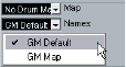
205
The MIDI editors
O-Note Conversion
This function on the MIDI menu goes through the selected
MIDI part(s) and sets the actual pitch of each note accord-
ing to its O-note setting. This is useful if you want to con-
vert a track to a “regular” MIDI track (with no drum map)
and still have the notes play back the correct drum sound.
A typical application is if you want to export your MIDI re-
cording as a standard MIDI file (see “Exporting and impor-
ting standard MIDI files” on page 259) – by first performing
an O-Note Conversion you make sure that your drum
tracks play back as they should when they are exported.
Using drum name lists
Even if no drum map is selected for the edited MIDI track,
you can still use the Drum Editor if needed. As previously
mentioned, the drum sound list will then only have four col-
umns: Audition, Pitch, Instrument (drum sound name) and
Quantize. There will be no I-note and O-note functionality.
In this mode, the names shown in the Instrument column
depend on the selection on the Names pop-up menu, just
below the Map pop-up in the Drum Editor.
The options on this pop-up menu are the currently loaded
drum maps plus a “GM Default” item which is always avail-
able. This means you can use the drum sound names in any
loaded drum map without using I-notes and O-notes, if you
want to.
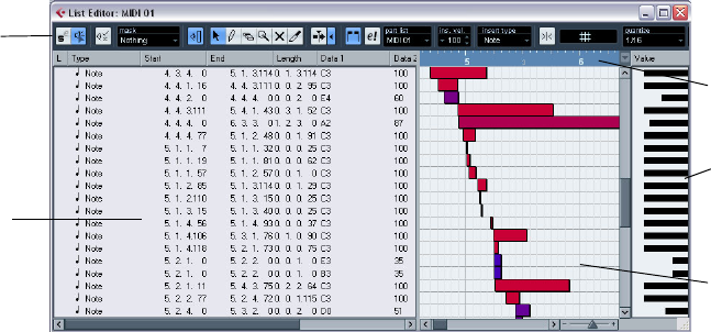
206
The MIDI editors
The List Editor – Overview
The toolbar
The toolbar contains several items that are the same as in
the Key Editor (edit solo, snap, quantize settings, etc.).
These are described earlier in this chapter. The following
toolbar items are unique to the List Editor:
•The Insert pop-up menu is used when creating new
events.
This is where you determine what type of event to add (see “Inserting
events” on page 207).
•The Mask pop-up menu and Filter view (Show Filter
View button) allow you to hide events from view, based on
their type and other properties.
See “Filtering” on page 208.
•The Value View button can be used for hiding and
showing the Value display (see below).
The List Editor has no info line (numerical editing is avail-
able in the list instead).
ÖIf you see an empty or incomplete list of items although
the items are visible in the Key Editor, check if you have ac-
tivated any filters (see “Filtering” on page 208).
The event list
This lists all events in the selected MIDI part(s), in the or-
der (from top to bottom) in which they are played back.
You can edit the event properties by using regular value
editing, see “Editing in the list” on page 207.
The event display
This shows the events graphically. The vertical position of
an event in the display corresponds to its entry in the list
(i.e. to the playback order), while the horizontal position cor-
responds to its actual position in the project. This is where
you add new parts or events, drag to move them, etc.
The value display
This display shows the “value” of each event, allowing for
easy viewing and graphical editing. Typically, the value
shown is the “Data 2” or “Value 2” property (amounts to
MIDI controller events, velocity for notes, etc.). You can
show or hide this display by clicking the “Show List Value
View” button on the toolbar.
Event display
Event list
Value
display
Ruler
Toolbar
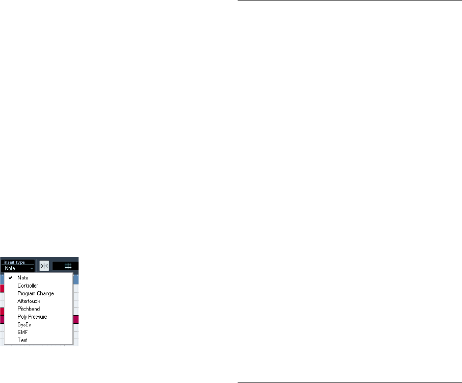
207
The MIDI editors
List Editor operations
Customizing the view
You can click and drag the divider between the list and
the event display to make one area wider and the other
narrower. Furthermore, the list can be customized in the
following ways:
•You can change the order of the columns by dragging
the column headings.
•You can resize columns by dragging the dividers be-
tween the column headings.
Setting the display format
Just like in the Project window, you set the display format
(bars+beats, seconds, etc.) by right-clicking in the ruler
and selecting an option from the pop-up menu. This set-
ting affects both the ruler and all start, end and length val-
ues shown in the list.
Zooming
You can change the horizontal magnification in the event
display by using the zoom slider below the display or the
Zoom tool (the magnification glass).
Inserting events
To add a new event to the edited part, proceed as follows:
1. Use the Insert Type pop-up menu on the toolbar to se-
lect the event type.
2. Select the Pencil tool and click in the event display at
the desired position (relative to the ruler).
If you are creating note events, you can click and drag to set the length of
the note.
The new event appears in the list and in the display. Its
properties will be set to default values, but can be ad-
justed in the list.
•Notes will get the insert velocity value set in the insert
velocity field on the toolbar, see “Setting velocity values”
on page 189.
Editing in the list
The list allows you to perform detailed numerical editing of
the events properties. The columns have the following
functionality:
Column Description
L An arrow in this column indicates the event that starts
closest before the project cursor position. If you click in
this column for an event, the project cursor is moved to
the start of that event. Double-clicking moves the cursor
position and starts/stops playback – useful for audition-
ing when editing in the list.
Type The event type. This cannot be changed.
Start The start position of the event, shown in the format se-
lected for the ruler. Changing this is the same as moving
the event. Note that moving the event past any other
event in the list will re-sort the list (the list always shows
the events in the order they are played back).
End This is only used for note events, allowing you to view and
edit the end position of a note (thereby resizing it).
Length This is only used for note events. It shows the length of
the note – changing this resizes the note and automati-
cally changes the End value as well.
Data 1 This is the “data 1” or “value 1” property of the event. The
content of this depends on the event type – for notes,
this is the pitch, for example. Where applicable, the val-
ues are shown in the most relevant form. For instance, the
Data 1 value for notes is shown as a note number in the
format selected in the Preferences (Event Display–MIDI
page). See also the table in the section “Editing in the va-
lue display” on page 209.
Data 2 This is the “data 2” or “value 2” property of the event. The
content of this depends on the event type – for notes,
this is the note-on velocity value, for example. See the ta-
ble in the section “Editing in the value display” on page
209.
Data 3 This is the “data 3” or “value 3” property of the event. This
value is only used for note events, where it corresponds
with the note-off velocity.
Channel The MIDI channel of the event. Note that this setting is
normally overridden by the channel setting for the track.
To make a MIDI event play back on “its own” channel, set
its track to channel “Any” in the Project window.
Comment This column is used for some event types only, providing
an additional comment about the event.
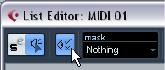
208
The MIDI editors
•You can edit several events at once. If several events
are selected and you edit a value for one event, the other
selected events’ values will be changed as well.
Normally, any initial value differences between the events will be main-
tained – i.e. the values will change by the same amount. If you press [Ctrl]/
[Command] when you edit, however, all events will get the same value.
ÖFor SysEx (system exclusive) events, you can only edit
the position (Start) in the list.
However, when you click the Comment column, the MIDI SysEx Editor
opens, in which you can perform detailed editing of system exclusive
events (see “Working with System Exclusive messages” on page 210).
Editing in the event display
The event display allows you to edit the events graphically
using the tools on the toolbar. You can edit single events
as well as several selected events simultaneously.
•To move an event, click and drag it to a new position.
Note that moving the event past any other event in the display will re-sort
the list (the list always shows the events in the order they are played
back). As a result, the vertical position of the event in the display will
change as well.
•To make a copy of an event, press [Alt]/[Option] and
drag it to a new position.
•To resize a note, select it and drag its end point with the
Arrow tool as in the Project window.
This only works with notes.
•To mute or unmute an event, click on it with the Mute
tool.
You can mute or unmute several events in one go by enclosing them in a
selection rectangle with the Mute tool.
•You can select a color scheme for the events with the
Colors pop-up menu on the toolbar.
This affects how all MIDI events are shown in the List, Key and Drum Ed-
itors – see “Coloring notes and events” on page 188.
•To delete an event, select it and press [Backspace] or
[Delete], or click on it with the Erase tool in the event dis-
play.
Filtering
Clicking the “Show Filter View” button on the toolbar
opens an additional filter bar that allows you to hide spe-
cific event types from view. For example, it may be hard to
find note events if the part contains a lot of controllers. By
hiding these, the list becomes more manageable.
•To hide an event type, activate its checkbox on the filter
view.
•To see one event type only (hide all other event types),
press [Ctrl]/[Command] and click its checkbox. If you
[Ctrl]/[Command]-click again, all checkboxes are cleared
(all events will be visible).
ÖThe event types remain hidden even if you close the fil-
ter view.
To make sure you see all events, open the filter view and check that all
checkboxes are deactivated.
ÖThe filter view does not remove, mute or change the
events in any way.
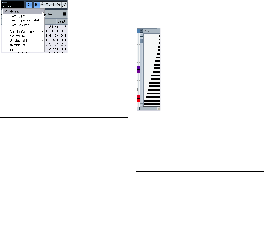
209
The MIDI editors
Masking
The Mask function is similar to the filter view but allows
you to hide events based on other criteria as well. Pro-
ceed as follows:
1. Select an event (or several events) of the type you want
to view.
2. Pull down the Mask pop-up menu on the toolbar and
select one of the options.
The results are as follows:
In addition to the above options, the menu also gives you
access to the Logical presets.
When you apply any of the Logical presets, only the
events that meet the criteria specified will be visible.
•To deactivate the Mask function, select “Nothing” from
the Mask pop-up menu.
The most typical usage of the Mask function is to view a
certain type of controller only (e.g. Modulation, Breath
Control, etc.). Since these are all the same event types
(controller), this would not be possible using the filter
view. With the “Event Types and Data 1” option on the
Mask pop-up menu, it is!
Editing in the value display
The value display to the right of the event display is a tool
for quick viewing and editing of multiple values, e.g. veloci-
ties or controller amounts. The values are shown as hori-
zontal bars, with the bar length corresponding to the value.
A velocity ramp in the value display
You edit the values by clicking and dragging. Note that the
pointer automatically takes on the shape of the Pencil tool
when you move it into the value display – you do not have
to select the Pencil tool for this.
Exactly which value is shown for an event depends on the
event type. The following table shows what is displayed
and edited in the Data columns and the value display:
•For note events there will also be a value in the Data 3
column, which is used for note-off velocity.
Option Description
Event Types Only events with the type of the selected event will be
shown. This does the same as the filter view but is
quicker if you only want to view a single event type.
Event Types
and Data 1 Only events of the same type and with the same “Data 1”
value will be shown. For example, if a note event is se-
lected, only notes with the same pitch will be shown. If a
controller event is selected, only controllers of the same
type will be shown.
Event
Channels Only events with the same MIDI channel value as the se-
lected event will be shown. Event type Data 1 Data 2 Value display
Note Pitch
(note number) Note-on
velocity Velocity
Controller Controller type Controller
amount Controller
amount
Program
Change Program
number Not used Program
number
Aftertouch Aftertouch
amount Not used Aftertouch
amount
Pitchbend Bend amount Not used Bend amount
SysEx Not used Not used Not used
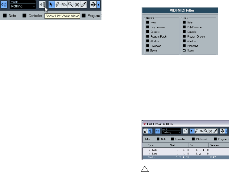
210
The MIDI editors
•The value display can be hidden from view by clicking the
“Show List Value View” button on the toolbar, so that it is
not lit.
Working with System Exclusive
messages
SysEx (System Exclusive) messages are model-specific
messages for setting various parameters of a MIDI device.
This makes it possible to address device parameters that
would not be available via normal MIDI syntax.
Every major MIDI manufacturer has its own SysEx identity
code. SysEx messages are typically used for transmitting
patch data, i.e. the numbers that make up the settings of
one or more sounds in a MIDI instrument.
Cubase AI allows you to record and manipulate SysEx
data in various ways. The following sections point to vari-
ous features that help you manage and create SysEx data.
Bulk dumps
Recording a bulk dump in Cubase AI
In any programmable device, the settings are stored as
numbers in computer memory. Change those numbers,
and you will change the settings.
Normally, MIDI devices allow you to dump (transmit) all or
some settings in the device’s memory in the form of MIDI
SysEx messages. A dump is therefore (among other
things) a way of making backup copies of the settings of
your instrument: sending such a dump back to the MIDI
device will restore the settings.
If your instrument allows the dumping of a few or all of its
settings via MIDI by activating some function on the front
panel, this dump will probably be recordable in Cubase AI.
1. Open the Preferences dialog from the File menu (on
the Mac, this is located on the Cubase AI menu) and select
the MIDI–MIDI Filter page.
This allows you to govern which MIDI event types should be recorded
and/or thru-put.
2. Make sure that recording of SysEx data is not filtered,
by deactivating the SysEx checkbox in the Record section.
The SysEx checkbox in the Thru section can be left as it is
(by default activated).
This way, SysEx messages will be recorded but not echoed back out to
the instrument (which might lead to unpredictable results).
3. Activate recording on a MIDI track and initiate the
dump from the front panel of the instrument.
4. When done recording, select the new part and open
the List Editor from the MIDI menu.
This allows you to check that the SysEx dump was recorded – there
should be one or several SysEx events in the part/event list.
Transmitting a bulk dump back to a device
1. Make sure the MIDI track with the System Exclusive
data is routed to the device.
You may want to check your device’s documentation to find details about
which MIDI channel should be used, etc.
2. Solo the track.
This might not be necessary, but it is a good safety measure.
!
If your MIDI instrument does not offer a way to initiate
a dump “by itself”, you have to send a Dump Request
message from Cubase AI to start the dump. In that
case, use the MIDI SysEx Editor (see “Editing System
Exclusive messages” on page 211) to insert the spe-
cific Dump Request message (see the instrument’s
documentation) at the beginning of a MIDI track.
When you activate recording, the Dump Request
message will be played back (sent to the instrument),
the dump will start and be recorded as above.
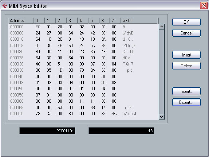
211
The MIDI editors
3. Make sure the device is set up to receive SysEx mes-
sages (often, receiving SysEx is turned off by default).
4. If necessary, put the device in “Standby to Receive
System Exclusive” mode.
5. Play back the data.
Some advice
• Do not transmit more data than you need. If all you want is a
single program, do not send them all, it will only make it harder
to find the one you want. Usually, you can specify exactly what
you want to send.
• If you want the sequencer to dump the pertinent sounds to
your instrument each time you load a project, put the SysEx
data in a silent “count-in” before the project itself starts.
• If the dump is very short (for instance, a single sound) you can
put it in the middle of the project to re-program a device on the
fly. However, you can achieve the same effect by using Program
Change. This is definitely preferable, since less MIDI data is
sent and recorded. Some devices may be set up to dump the
settings for a sound as soon as you select it on the front panel.
• If you create parts with useful SysEx dumps, you can put these
on a special muted track. When you want to use one of them,
drag it to an empty unmuted track and play it back from there.
• Do not transmit several SysEx dumps to several instruments at
the same time.
• Make a note of the current device ID setting of the instrument.
If you change this, the instrument may refuse to load the dump
later.
Recording System Exclusive
parameter changes
Often you can use SysEx to remotely change individual
settings in a device, e.g. open a filter, select a waveform,
change the decay of the reverb etc. Many devices are also
capable of transmitting changes made on the front panel
as SysEx messages. These can be recorded in Cubase AI,
and thus incorporated into a regular MIDI recording.
Here’s how it works: let’s say you open up a filter while
playing some notes. In that case, you will record both the
notes and the SysEx messages generated when you
opened of the filter. When you play it back, the sound
changes exactly like it did when you recorded it.
1. Open the Preferences dialog from the File menu, se-
lect the MIDI–MIDI Filter page and make sure that SysEx is
recorded, i.e. the SysEx checkbox in the Record section is
deactivated.
2. Make sure the instrument is actually set to transmit
changes of front panel controls as SysEx messages.
3. Record normally.
When you’re done, you can check that the events were recorded pro-
perly in the List Editor.
Editing System Exclusive messages
While SysEx events are shown in the List Editor, their en-
tire content is not (only the beginning of the message is
displayed in the Comment column for the event). Also, you
cannot edit the event (other than moving it) as you can
with other event types in the List Editor.
Instead, you have to use the MIDI SysEx Editor for this.
•To open the MIDI SysEx Editor for an event, click in the
Comments column for the event in the List Editor.
The display shows the entire message on one or several
lines. SysEx messages always begin with F0 and end with
F7 with a number of arbitrary bytes in between. If the mes-
sage contains more bytes than fit on one line, it continues
on the next. The Address indication to the left helps you
find out on which position in the message a certain value
resides.
You can edit all values except for the first (F0) and last one
(F7).
212
The MIDI editors
Selecting and viewing values
To select a value, either click on it or use the cursor keys.
The selected byte is displayed in various formats:
• In the main display, values are shown in hexadecimal format.
• To the right of this, values are shown in ASCII format.
• At the bottom of the dialog, the selected value is shown in
binary and decimal formats.
Editing a value
The selected value can be edited directly in the main dis-
play or in the decimal and binary displays. Just click on it
and type in the desired value as usual.
Adding and deleting bytes
Using the Insert and Delete buttons or their corresponding
computer keyboard keys, you can add and delete bytes
from the message. Inserted data will appear before the se-
lection.
To delete the complete SysEx message, select it in the
List Editor and press [Delete] or [Backspace].
Importing and exporting data
The Import and Export buttons allow you to get SysEx data
from disk and to export the edited data to a file. The file
has to be in “MIDI SysEx” (.SYX) binary format. Only the
first dump in a .SYX file will be loaded.
This format should not be confused with MIDI files, which
have the extension .MID.
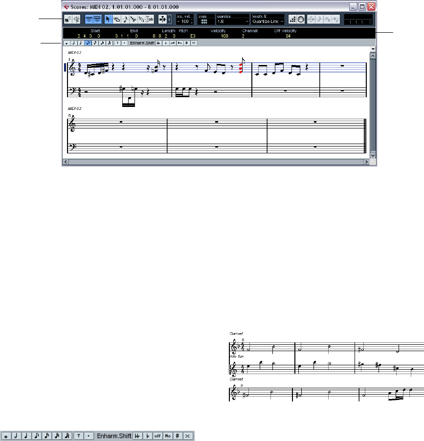
213
The MIDI editors
The Score Editor – Overview
The Score Editor shows the MIDI notes as a musical score.
The window contains the following sections and items:
The toolbar
The Score Editor toolbar is similar to the toolbar in the Key
Editor, with the following differences:
• The Score Editor toolbar has a button for showing or hiding
the extended toolbar (see below).
• There are no active part settings – in the Score Editor, parts
on different tracks are shown on different staves.
• There are no chord recognition functions.
The info line
The info line shows information about selected MIDI
notes, just like in the Key and Drum Editors. You can edit
all values on the info line using regular value editing (see
“Editing on the info line” on page 192 for details).
•To hide or show the info line, click the “Show Info” but-
ton in the toolbar.
The extended toolbar
The extended toolbar (shown or hidden by clicking the
“Show Tool Strip” button on the main toolbar) contains
the following items:
Note value buttons
Click one of these to select a note value for input. The “T”
and “.” options are for triplet and dotted note values. You
can also press [Ctrl]/[Command] and click one of the note
value buttons – this will resize all selected notes to the
note value you choose.
Enharmonic shift
Allows you to manually select whether a note should be
shown with flat or sharp accidentals, see “Enharmonic
Shift” on page 219.
The score display
The main area of the Score Editor window shows the
notes in the edited parts on one or several staves.
•If you are editing one or several parts on the same track,
as much of them as possible is shown on several staves –
one above the other – just as with a score on paper.
Toolbar
Info line
Extended
Toolbar
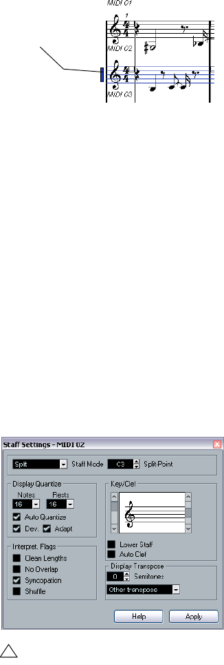
214
The MIDI editors
•If you are editing parts on several tracks, they are put on
a grand staff (multiple staves, tied together by bar lines).
•The number of bars across the screen depends on the
size of the window and the number of notes in each bar.
The maximum number of bars across the page is four.
•The end of the last part is indicated by a double bar line.
•Unlike the other MIDI editors, the Score Editor does not
have a ruler.
A conventional ruler would not make sense, since there is no exact rela-
tionship between a note’s horizontal position in the score and its musical
position in the project.
Score Editor operations
Opening the Score Editor
To open one or several parts in the Score Editor, select
one or several tracks or any number of parts (on the same
or different tracks), and select “Open Score Editor” from
the Scores submenu on the MIDI menu. The default key
command for this is [Ctrl]/[Command]-[R].
•You can also select the Score Editor as your default ed-
itor, allowing you to open it by double-clicking parts.
This is done with the Default Edit Action pop-up menu in the Preferences
dialog (Event Display–MIDI page).
About editing parts on different tracks
If you have selected parts on two or more tracks and open
the Score Editor, you will get one staff for each track (al-
though you can split a staff in two, e.g. when scoring for
piano). The staves are tied together by bar lines and
placed in the order of the tracks in the Project window.
•If you need to rearrange the staves: close the editor, go
back into the Project window, drag the tracks to the order
you want them, and open the Score Editor again.
The active staff
Just as in the other editors, all MIDI input (as when record-
ing from your instrument) is directed to one of the tracks,
here called the active staff. The active staff is indicated by
a blue rectangle to the left of the cleft symbol.
To change the active staff, click on the staff you want to
activate.
Getting the score displayed correctly
When you open the Score Editor for a part recorded in
real time, the score may not look as legible as you expect.
The Score Editor can ignore the minor time variances in
performance and make a neater score almost instantly. To
achieve this, there are a number of Staff Settings that de-
termine how the program displays the music.
ÖNote that the time signature follows the time signa-
ture(s) set in the Tempo Track Editor, and that these set-
tings are common to all tracks/staves in the score.
There are two ways to open the Staff Settings dialog:
•Double-click in the area to the left of the staff.
•Activate a staff by clicking in it, and select “Staff Set-
tings…” from the Scores submenu on the MIDI menu.
The Staff Settings dialog appears.
!
The settings you make in this dialog are independent
for each staff (track), but common for a piano staff
which you have created by choosing the “Split” Staff
Mode option (see below).
The active staff
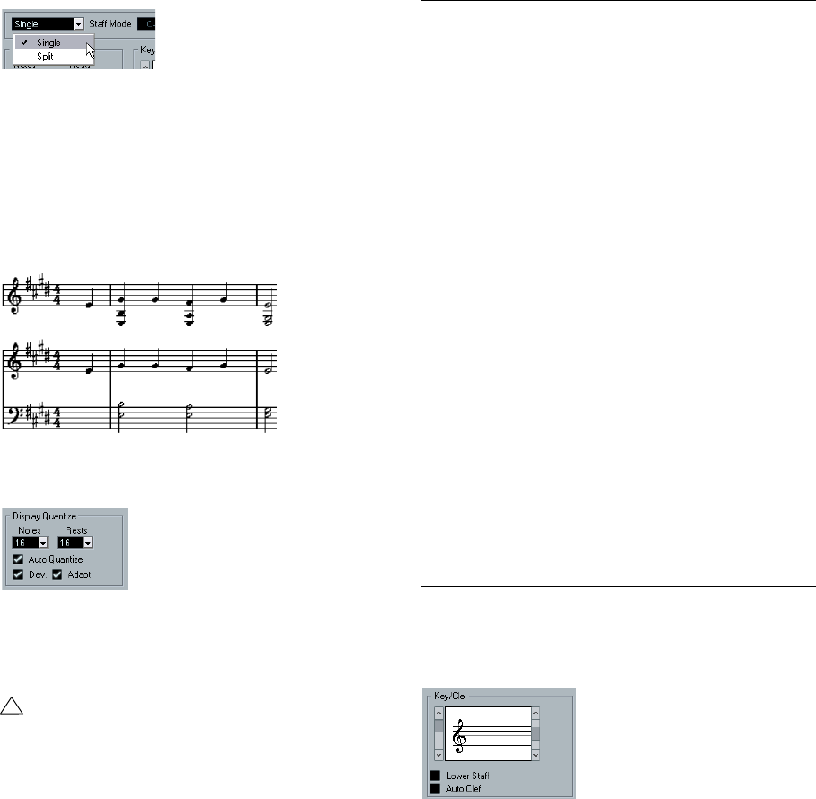
215
The MIDI editors
Staff Mode
This pop-up menu determines how the staff is shown:
•When set to “Single”, all notes in the part are shown in
the same staff.
•When set to “Split”, the part is split on the screen into a
bass and treble clef, as in a piano score.
You use the Split-Point value field to set the note where you want the
split to occur. Notes above and including the split note will appear on the
upper staff, and notes below the split note will appear on the lower staff.
Before and after setting a split at C3.
Display Quantize
Notes are not an absolute language, and you must give
the program a few hints on how the score should be dis-
played. This is done using the Display Quantize section of
the Staff Settings dialog.
Here is a description of the functions:
Key and Clef
The correct Key and Clef are set using the two scroll bars
in the Key/Clef section.
If you activate the “Auto Clef” checkbox, the program attempts to guess
the correct clef, judging from the pitch of the music.
•To set the clef and key for the lower staff, activate the
“Lower Staff” checkbox in the Key/Clef section.
!
These are only display values used for the graphics
in the Score Editor. They do not affect the actual
playback in any way.
Parameter Description
Notes Determines the smallest note value to be displayed and
the “smallest position” to be recognized and properly dis-
played. Set this to the smallest significant note position
used in your music.
For example, if you have notes on odd sixteenth note po-
sitions, you should set this value to 16.
The “T” values are for triplet note values.
This setting is partly overridden by Auto Quantize (see
below).
Rests This value is used as a “recommendation” – the program
will not display rests smaller than this value, except where
necessary. In effect, this setting also determines how the
length of notes should be displayed. Set this value ac-
cording to the smallest note value (length) you want to be
displayed for a single note, positioned on a beat.
Auto Quantize Generally, if your music contains mixed triplets and
straight notes, try activating this checkbox. Otherwise,
make sure it is deactivated.
Auto Quantize is used to make your score look as legible
as possible. Auto Quantize allows you to mix straight
notes with tuplets (triplets) in a part. But Auto Quantize
also uses the (display) Quantize value. If it can not find an
appropriate note value for a certain note or group of
notes, it will use the set Quantize value to display it.
If the part is imprecisely played and/or complex, Auto
Quantize may have a problem “figuring out” exactly what
you “mean”.
Dev. This option is only available if Auto Quantize is on. When
Dev. (Deviation) is activated, triplets/straight notes will be
detected even if they are not exactly “on the beat”. How-
ever, if you know your triplets/straight notes are perfectly
recorded (quantized or entered by hand), turn this off.
Adapt This option is only available if Auto Quantize is on. When
Adapt is activated, the program “guesses” that when one
triplet is found, there are probably more triplets surround-
ing it. Turn this on if not all of your triplets are detected.
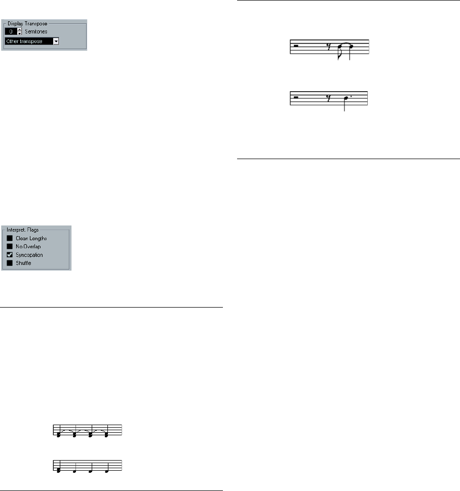
216
The MIDI editors
Display Transpose
Some instruments, for example a lot of brass instruments,
are scored transposed. For this purpose, the Staff Set-
tings dialog allows you to specify a separate Display
Transpose setting for each staff (track). This transposes
the notes in the score (i.e. how they are displayed) without
affecting how the notes play back. This allows you to
record and play back a multi staff arrangement, and still
score each instrument according to its own transposition.
•Use the pop-up menu to select the instrument for which
you are scoring.
You can also manually set a display transpose value with the Semitones
box above.
Interpret. Flags
These provide additional options for how the score should
be displayed:
Applying your settings
After you have made your settings, click Apply to apply
them to the active staff. You can select another staff in the
score and make settings for that, without having to close
the Staff Settings dialog first – just remember to click Ap-
ply before you change staff, otherwise your changes will
be lost.
Entering notes with the mouse
To enter notes into a part in the Score Editor, you use the
Note tool. However, first you need to set the note value
(length) and spacing:
Selecting a note value for input
This can be done in two ways:
•By clicking the note symbols on the extended toolbar.
You can select any note value from 1/1 to 1/64th and turn on and off the
dotted and triplet options by clicking the two buttons to the right. The se-
lected note value is displayed in the Length value field on the toolbar and
in the Note tool cursor shape.
•By selecting an option from the Length Q pop-up on the
toolbar.
Selecting a Quantize value
When you move the mouse pointer over the score, you will
see that the position box on the toolbar tracks your move-
ment and shows the current position in bars, beats, six-
teenth notes and ticks.
Parameter Description
Clean Lengths When this is activated, notes that are considered to be
chords will be shown with identical lengths. This is done
by showing the longer notes as shorter than they are.
When Clean Lengths is turned on, notes with very short
overlaps are also cut off; a bit as with No Overlap (see
below), but with a more subtle effect.
No Overlap When this is activated one note will never be shown as
overlapping another, lengthwise. This allows long and
short notes starting at the same point to be displayed
without ties; the long notes are cut off in the display. This
will make the music more legible.
An example measure with No Overlap deactivated…
…and with No Overlap activated.
Syncopation When this function is activated, syncopated notes are
shown in a more legible way.
This is a dotted quarter at the end of a bar when Syn-
copation is Off…
…and when it is On.
Shuffle Activate this function when you have played a shuffle
beat and want it displayed as straight notes (not triplets).
This is very common in jazz notation.
Parameter Description
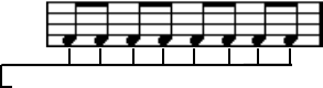
217
The MIDI editors
Positioning on screen is controlled by the current Quantize
value. If, for example, you set this to 1/8 you can only insert
and move notes to eighth note positions, at quarter notes,
at half bars or at bar positions. It is a good strategy to set
the Quantize value to the smallest note value in the piece.
This does not stop you from inputting notes at “coarser”
positions. However, if you set the Quantize value to too
small a note value, it is easier to make mistakes.
The Quantize value is set with the Quantize pop-up menu
on the toolbar.
•You can also assign key commands to the different
Quantize values.
This is done in the Key Commands dialog, in the “MIDI Quantize” cate-
gory.
•Just like in the other MIDI editors, you can use the
Quantize Setup dialog to create other quantize values, ir-
regular grids, etc.
However, this is not often used when entering score notes.
Entering a note
To add a note to the score, proceed as follows:
1. Make the staff active.
Notes are always put in on the active staff.
2. Select the type of note by selecting a note value.
This is described in detail above.
3. If you selected the note value by clicking on a symbol
on the extended toolbar, the Note tool was automatically
selected – otherwise select the Note tool from the toolbar
or context menu.
4. Select a Quantize value.
As described above, the Quantize value will determine the spacing be-
tween notes. If you have Quantize set to 1/1 you will only be able to add
notes at downbeats. If you set Quantize to 1/8 you will be able to add
notes at all eighth note positions etc.
5. Click in the staff and keep the mouse button pressed.
A note appears under the mouse pointer.
6. Move the mouse horizontally to find the correct posi-
tion.
Check the lower mouse position box on the toolbar – the position is
“magnetically” attracted to the grid defined by the current Quantize
value. This allows you to easily find the correct position.
7. Move the mouse vertically to find the correct pitch.
The upper mouse position box shows the pitch at the pointer position,
making it easy to find the right pitch.
8. Release the mouse button.
The note appears in the score.
The notes you enter will get the insert velocity value set in
the insert velocity field on the toolbar, see “Setting velocity
values” on page 189.
Selecting notes
There are several ways to select notes in the Score Editor:
By clicking
To select a note, click on its note head with the Arrow tool.
The note head gets red to indicate that it is selected.
•To select more notes, hold down [Shift] and click on
them.
•To deselect notes, hold [Shift] down and click on them
again.
•If you hold down [Shift] and double-click on a note, this
note and all the following notes in the same staff are se-
lected.
Using a selection rectangle
1. Press the mouse button with the Arrow tool in some
free (white) space in the score.
2. Drag the mouse pointer to create a selection rectangle.
You can drag to select notes on several voices or staves if you wish.
3. Release the mouse button.
All notes with their note heads inside the rectangle get selected.
If you want to deselect one or more of the notes, hold
down [Shift] and click as described above.
Using the keyboard
By default, you can step through the notes in the staff us-
ing the left and right arrow keys. If you press [Shift], you
will select the notes as you step through them.
With the Quantize value set to 1/8, you can only input
notes at eighth note positions.
218
The MIDI editors
•If you want to use other keys for selecting notes, you
can customize the settings in the Key Commands dialog
(in the Navigate category).
Deselecting everything
To deselect everything, simply click with the Arrow tool in
some “free” (white) space in the score.
Deleting notes
Notes can be deleted in two ways:
Using the Erase tool
1. Select the Erase tool from the toolbar or context menu.
2. One at a time, click on the note(s) you want to erase,
or drag over them with the mouse button pressed.
Using the keyboard or delete menu item
1. Select the note(s) you want to delete.
2. Select Delete from the Edit menu, or press [Delete] or
[Backspace] on the computer keyboard.
Moving notes
To move or transpose notes, proceed as follows:
1. Set the Quantize value.
The Quantize value will restrict your movement in time. You cannot place
the notes on positions smaller than the Quantize value. If Quantize for ex-
ample is set to 1/8, you will not be able to move the notes to a sixteenth
note position. However, you will be able to put them on any eighth note,
quarter note, half note or whole note position.
2. If you want to hear the pitch of the note while moving,
activate the speaker icon on the toolbar.
When it is on, you will hear the current pitch of the “dragged” note.
3. Select the note(s) you plan to move.
4. Click one of the selected notes and drag it to a new
position and/or pitch.
The horizontal movement of the note is “magnetically attracted” to the
current Quantize value. The position boxes on the toolbar show what the
new position and pitch for the dragged note will be.
5. Release the mouse.
The notes appear at their new position.
•If you hold [Ctrl]/[Command] and drag, movement is re-
stricted to vertical or horizontal (depending on the direc-
tion in which you drag).
•You can also move selected notes by using key com-
mands, as assigned in the Nudge category in the Key
Commands dialog.
When moving notes to the left or right using key commands, the notes
will be moved in steps according to the current Quantize value. The keys
assigned for up/down nudging will transpose notes in semitone steps.
Duplicating notes
1. Set the Quantize value and select the notes, as for
moving.
2. Hold down [Alt]/[Option] and drag the notes to their
new position.
•If you want to restrict movements to one direction, press
[Ctrl]/[Command].
This works just as for moving, as described above.
•[Alt]/[Option] is the default modifier key for copying/du-
plicating. If you like, you can change this in the Prefer-
ences dialog (Editing–Tool Modifiers page).
The entry for this is found in the Drag & Drop category (“Copy”).
Changing the length of notes
As described earlier (see “Getting the score displayed
correctly” on page 214), the displayed length of a note is
not necessarily the actual note length, but also depends
on the Notes and Rests values for Display Quantize in the
Staff Settings dialog. This is important to remember when
you change the length of a note, since it can lead to con-
fusing results.
There are several ways to change the length of a note in
the Score Editor:
By using the Note tool
1. Select the notes you want to change.
2. Select a Note value that you wish to apply to the
note(s).
This can be done by clicking a note value icon in the extended toolbar or
by selecting a new Length value.
3. Select the Note tool if it is not already selected.
4. Hold down [Alt]/[Option] and click on the notes you
wish to set to this length.
219
The MIDI editors
By using the note value icons on the extended toolbar
Using the extended toolbar is another quick way to set a
number of notes to the same length:
1. Select the notes you want to change.
2. Hold down [Ctrl]/[Command] and click on one of the
note icons on the extended toolbar.
All the selected notes are now given the length of the clicked note.
By using the info line
You can also edit length values numerically on the info
line, just like in the Key and Drum Editors (see “Editing on
the info line” on page 192).
Splitting and Gluing notes
•If you have two notes strung together by a tie, and click
on the “tied” note head with the Scissors tool, the note will
be divided into two, with the respective length of the
“main” and the tied note.
•Conversely, if you click on a note with the Glue Tube
tool it will be joined to the next note with the same pitch.
Enharmonic Shift
The buttons to the right on the extended toolbar allow you
to shift the display of selected notes so that for example
an F# (F sharp) is instead shown as a Gb (G flat) and vice
versa:
1. Select the note(s) you want to affect.
2. Click on one of the buttons to display the selected
note(s) a certain way.
The “off” button resets the notes to original display. The other five op-
tions are double flats, flats, No (no accidentals shown, regardless of
pitch), sharps and double sharps.
Flip Stems
Normally the direction of the note stems is automatically
selected according to the note pitches, but you can
change this manually if you like:
1. Select the notes for which you want to change (flip) the
stem direction.
2. Pull down the MIDI menu and select Flip Stems from
the Scores submenu.
Working with text
You can use the Text tool to add comments, articulation or
instrumentation advice and other text strings anywhere in
the score:
Adding a text string
1. Select the Text tool from the toolbar or context menu.
2. Click anywhere in the score.
A text input line dialog box appears.
3. Enter the text and press [Return].
Editing text
To edit an already added text string, double-click it with
the Arrow tool. This opens the text for editing, and you can
use the arrow keys to move the cursor, delete characters
with the [Delete] or [Backspace] keys and type new text as
usual. Finish by pressing [Return].
•To delete a text block, select it with the Arrow tool and
press [Backspace] or [Delete].
•You can move or duplicate text blocks by dragging (or
[Alt]/[Option]-dragging) them, just as with notes.
Changing the text font, size and style
To change the font settings for the text you have added,
proceed as follows:
1. Select the text by clicking it with the Arrow tool.
2. Pull down the MIDI menu and select “Set Font…” from
the Scores submenu.
The Font Settings dialog appears, containing the following settings:
Item Description
Font This is where you specify the font for the text. Which
fonts are available on the pop-up menu depends on the
fonts you have installed on you computer. You probably
do not want to use the “Steinberg” fonts – these are spe-
cial fonts used by the program (e.g. for score symbols)
and not suited for common text.
Size Sets the size of the text.
Frame Allows you to encase the text in a rectangular (box) or
oval frame.
Font options These checkboxes determine whether the text should be
bold, italic, and/or underlined.

220
The MIDI editors
3. When you have made your settings, click Apply.
If you like, you can leave the Font Settings dialog open, select another
text block and adjust the settings for that – just remember to click Apply
before you select a new text block.
•If you make settings in the Font Settings dialog with no
text selected, the settings will be used as default for all
new text.
In other words, all text you enter from then on will get the settings you
have specified (although you can of course change this manually for
each text as usual).
Printing
To print your score, proceed as follows:
1. Open the parts you want to print in the Score Editor.
Printing is only available from within the Score Editor.
2. Select “Page Setup…” from the File menu and make
sure all your printer settings are correct. Close the dialog.
3. Select “Print…” from the File menu.
4. A standard print dialog appears. Fill out the options as
desired.
5. Click Print.
!
If you change your setting for paper size, scale and
margins now, the score may change its look.
20
Editing tempo and signature
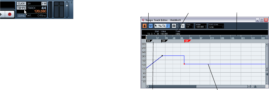
222
Editing tempo and signature
Background
Whenever you create a new project, Cubase AI will auto-
matically set the tempo and time signature for this project.
The tempo and signature settings can be displayed in the
Tempo Track Editor.
Tempo modes
Before we go into detail about tempo and signature set-
tings, you should understand the different tempo modes.
For tempo-based tracks, the tempo can either be fixed
throughout the entire project (this is called “fixed tempo
mode”) or follow the tempo track (this is called “tempo
track mode”), which may contain tempo changes.
•To switch between fixed tempo mode and tempo track
mode, use the Tempo button on the Transport panel:
When the Tempo button is lit (and the text “Track” is
shown), the tempo follows the tempo track; when it is de-
activated (and the text “Fixed” is shown), a fixed tempo is
used (see “Setting the fixed tempo” on page 224). You
can also switch the tempo mode with the Activate Tempo
Track button on the Tempo Track Editor toolbar.
In tempo track mode, the tempo cannot be changed on
the Transport panel, i.e. the tempo information here is for
display purposes only.
Signature events are always active, regardless of whether
fixed tempo mode or tempo track mode is selected.
A note about tempo-based audio tracks
For tempo-based tracks, the start position of audio events
on the timeline depends on the current tempo setting. How-
ever, it is important to realize that the actual audio (“within”
the events) will play back as recorded, regardless of any
tempo changes you make. Therefore, it is good practice to
make the proper tempo and time signature settings before
you start recording tempo-based audio.
ÖTo make an already recorded audio track follow the
tempo changes, you can use the Sample Editor, see the
chapter “The Sample Editor” on page 124.
How well this works depends on the character of the audio recordings,
since the hitpoint detection feature works best with fairly rhythmical
material.
Tempo and signature display
You can view the current tempo and signature settings of
your project in a number of ways:
•On the Transport panel.
See above, and the section “The Transport panel” on page 43.
•In the Tempo Track Editor.
Open the Project menu and select Tempo Track Editor, or [Ctrl]/[Com-
mand]-click the Tempo button on the Transport panel.
About the Tempo Track Editor
The Tempo Track Editor has a toolbar, info line and ruler
just like other editors in Cubase AI, plus an area for the dis-
play of time signature events and a tempo curve display.
Toolbar Info line Ruler
Time Signature area Tempo curve display
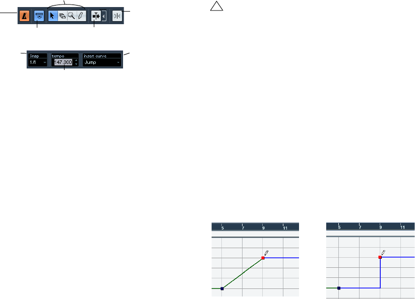
223
Editing tempo and signature
The toolbar
The toolbar contains various tools and settings:
•The tools for Object Selection, Erase, Zoom and Draw
are used in the same way as in other editors. The Snap
and Autoscroll functions also work exactly like in the
Project window.
Note that in the Tempo Track Editor, the Snap function affects tempo
events only. Time signature events always snap to the beginning of bars.
•The info line in the Tempo Track Editor allows you to
change settings for selected time signature events, and
the type and tempo of selected tempo curve points.
•The ruler in the Tempo Track Editor shows the timeline,
and is similar to the ruler in the Project window. See “The
ruler” on page 21 for details.
•The area below the ruler shows time signature events.
•The main display shows the tempo curve (or, if fixed
tempo mode is selected, the fixed tempo – see “Setting
the fixed tempo” on page 224). To the left of the display
you will find a tempo scale to help you quickly locate the
desired tempo.
Note that the vertical “grid lines” in the tempo curve display correspond
to the display format selected for the ruler.
Editing tempo and signature
Editing the tempo curve
Adding tempo curve points
1. Use the “Insert curve” pop-up menu in the toolbar of the
Tempo Track Editor to select whether you want the tempo
to change gradually from the previous curve point to the new
one (“Ramp”) or change instantly to the new value (“Jump”).
You can also set this to Automatic. In this case, the types of existing tempo
curve points will be used when inserting new points at the same position.
2. Select the Pencil tool.
3. Click and drag in the tempo curve display to draw a
tempo curve.
When you click, the tempo display in the toolbar shows the tempo value. If
Snap is activated on the toolbar, this determines at which time positions
you can insert tempo curve points, see “The Snap function” on page 40.
•You can also click on the tempo curve with the Arrow
tool.
This adds a single point with each click.
Tools
Activate
Tempo
Track
Autoscroll
Snap on/off
Show Info
Curve type for new
tempo events
The selected tempo
Snap pop-up
!
This section assumes that you are working in tempo
track mode, i.e. the Tempo button must be activated
on the Transport panel.
Insert curve set to “Ramp” Insert curve set to “Jump”
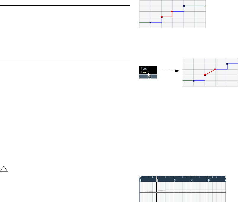
224
Editing tempo and signature
Selecting tempo curve points
Curve points can be selected as follows:
•Using the Arrow tool.
The standard selection techniques apply.
•Using the Select submenu on the Edit menu.
The options are:
•You can also use the left and right arrow keys on the
computer keyboard to go from one curve point to the next.
If you press [Shift] and use the arrow keys, you can select several points
at the same time.
Editing tempo curve points
Curve points can be edited in the following ways:
•By clicking and dragging horizontally and/or vertically
with the Arrow tool.
If several points are selected, all of them are moved. If Snap is activated
on the toolbar, this determines to which time positions you can move
curve points, see “The Snap function” on page 40.
•By adjusting the tempo value. You can do this in the
tempo display on the Tempo Track Editor toolbar.
Adjusting the curve type
You can change the curve type of a tempo curve segment
at any time, using the following method:
1. With the Arrow tool, select all curve points within the
segment you want to edit.
2. In the info line, click below the word “Type” to switch
the curve type between “Jump” and “Ramp”.
The curve sections between the selected points are adjusted.
Removing tempo curve points
To remove a curve point, either click on it with the Erase
tool or select it and press [Backspace]. The first tempo
curve point cannot be removed.
Setting the fixed tempo
When the tempo track is deactivated, the tempo track
curve is grayed out (but still visible). Since the tempo is
fixed throughout the whole project, there are no tempo
curve points. Instead, the fixed tempo is displayed as a
horizontal black line in the tempo curve display.
To set the tempo in fixed mode:
•Adjust the value numerically in the tempo display on the
Tempo Track Editor toolbar.
•On the Transport panel, click on the tempo value to se-
lect it, enter a new value and press [Enter].
Option Description
All Selects all curve points on the tempo track.
None Deselects all curve points.
In Loop Selects all curve points between the left and right locator.
From Start
to Cursor Selects all points to the left of the project cursor.
From Cursor
to End Selects all points to the right of the project cursor.
!
Dragging tempo curve points with a time-based dis-
play format (any other format than “Bars+Beats”) may
lead to confusing results. This is because moving a
point will change the relationship between tempo and
time. Let’s say you move a tempo point to the right and
drop it at a certain time position. When you release
the mouse button, the mapping between tempo and
time will be adjusted (since you have changed the
tempo curve). As a result, the moved point will appear
at another position. For this reason, we recommend
using the Bars+Beats display format when editing
tempo curves.
225
Editing tempo and signature
Adding and editing time signature events
•To add a time signature event, click in the time signature
area with the Pencil tool.
This adds a default 4/4 time signature event at the closest bar position.
•To edit the value of a time signature event, select it and
adjust the value on the info line, or double-click the event
and enter a new value.
Note that there are two controls for the signature display; the left one ad-
justs the numerator and the right one adjusts the denominator.
•You can move a time signature event by clicking and
dragging it with the Arrow tool.
Note that you can [Shift]-click to select multiple events. Also note that
time signature events can only be positioned at the start of bars. This is
also true if Snap is deactivated.
•To remove a time signature, either click on it with the
Erase tool or select it and press [Backspace] or [Delete].
The first time signature event cannot be removed.
21
Export Audio Mixdown
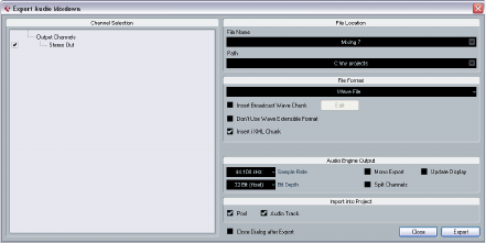
227
Export Audio Mixdown
Introduction
The Export Audio Mixdown function in Cubase AI allows
you to mix down audio from the program to a file on your
hard disk.
You always mix down an output channel. For example, if
you have set up a stereo mix with tracks routed to a stereo
output bus, mixing down that output bus would give you a
mixdown file containing the whole mix.
Please note the following:
•The Export Audio Mixdown function mixes down the
area between the left and right locators.
•When you mix down, you get what you hear – mutes,
mixer settings and insert effects are taken into account.
Note though that you will only include the sound of the channel you se-
lect for mixdown.
•MIDI tracks are not included in the mixdown!
To make a complete mixdown containing both MIDI and audio, you first
need to record all your MIDI music onto audio tracks (by connecting the
outputs of your MIDI instruments to your audio inputs and recording, as
with any other sound source).
Mixing down to audio files
1. Set up the left and right locators to encompass the
section you want to mix down.
2. Set up your tracks so that they play back the way you
want.
This includes muting unwanted tracks or parts, making manual mixer set-
tings and/or activating the R (Read) automation buttons for some or all
mixer channels.
3. Pull down the File menu and select “Audio Mixdown…”
from the Export submenu.
The Export Audio Mixdown dialog appears.
The available settings and options differ depending on the
selected file format (see “The available file formats” on
page 228).
4. In the Channel Selection section to the left, select the
channel you want to mix down. The list contains all output
channels available in the project (see “About the Channel
Selection section” on page 228).
5. In the File Location section at the top you can specify
a name and path for the mixdown file.
To the right of the File Name and the Path fields you will
find two pop-up menus with a number of options:
Naming Options pop-up menu:
•Select “Set to Project Name” to use the project name
for the export file.
•Activate the “Auto Update Name” option (so that a
checkmark is displayed before it) to add a number to the
specified file name every time you click the Export button.
Path Options pop-up menu:
•Select “Choose…” to open a dialog in which you can
browse for a path and enter a file name.
The file name will automatically be shown in the File Name/Prefix field.
•Select an entry from the Recent Paths section to reuse
a path specified for a previous export.
This section is only shown after an export has been completed. With the
“Clear Recent Paths” option you can delete all entries from the Recent
Paths section.
•Activate the option “Use Project Audio Folder” to save
the mixdown file in the project’s Audio folder.
6. Choose an entry from the File Format pop-up menu.
7. Activate the Split Channels option if you want to export
the two channels of a stereo bus as separate mono files.
8. Make additional settings for the file to be created.
This includes selecting sample rate, bit depth, etc. The available options
depend on the selected file format – see “The available file formats” on
page 228.
9. If you want to automatically import the resulting audio
file back into Cubase AI, activate any of the checkboxes in
the “Import into project” section.
If you activate the Pool checkbox, a clip referring to the file will appear in
the Pool. Activating the Audio Track checkbox as well will create an au-
dio event that plays the clip, and place it on a new audio track, starting at
the left locator.

228
Export Audio Mixdown
10. If you activate Update Display, the meters will be up-
dated during the export process.
This allows you to check for clipping, for example.
11. Click Export.
A dialog with a progress bar is displayed while the audio file
is created. If you change your mind during the file creation,
you can click the Abort button to cancel the operation.
•If the option “Close dialog after export” is activated, the
dialog will be closed.
•If you have activated any of the “Import into project” op-
tions, the file will be imported back into the same project.
When playing back the re-imported file, remember to mute the original
tracks so that you really hear the correct file.
About the Channel Selection section
The Channel Selection section shows all output and au-
dio-related channels available in the project. These chan-
nels are organized in a hierarchical structure that allows
you to easily identify and select the channels you want to
export. The different channel types are listed below each
other, with channels of the same type being grouped in a
node (e.g. Instrument Tracks).
•You can activate/deactivate channels by clicking on the
checkboxes in front of the channel names.
About the Import Options dialog
If you activate any of the options in the Import into project
section, the Import Options dialog will open when the ex-
port is complete. For a detailed description of the options
in this dialog see “About the Import Medium dialog” on
page 151.
The available file formats
The following pages describe the different export file for-
mats, as well as their options and settings.
• AIFF files (see “AIFF files” on page 228).
• AIFC files (see “AIFC files” on page 229).
• Wave files (see “Wave files” on page 229).
• Broadcast Wave files (see “Broadcast Wave files” on page
230).
• MP3 files (see “MPEG 1 Layer 3 files” on page 230).
• Windows Media Audio files (Windows only, see “Windows
Media Audio files (Windows only)” on page 230).
ÖMost of the settings described below for AIFF files are
available for all file types. Where this is not the case, you will
find additional information in the corresponding section.
MP3 Export
This version of Cubase AI provides a function for exporting
your audio mixdown as mp3 files. This function is limited to
20 trial encodings or a trial period of 30 days from the in-
stallation date (whichever ends first). After this period, the
function will be disabled until you purchase the mp3 en-
coder for Cubase AI.
•When the mp3 format is selected, and you click the Ex-
port button, a window opens showing you how many trial
encodings you have left. You can upgrade to an unlimited
mp3 export function by clicking the “Go to Online Shop”
button in the dialog.
This will take you to Steinberg’s online shop where you can purchase the
upgrade. Note that a working internet connection is required.
AIFF files
AIFF stands for Audio Interchange File Format, a standard
defined by Apple Inc. AIFF files have the extension “.aif”
and are used on most computer platforms.
For AIFF files the following options are available:
Option Description
File Name In this field you can enter a name for the mixdown file.
Naming options
pop-up menu This allows you to define how your project should be
named. If you select “Set to Project Name” the project
name will be used for the export file. If you activate the
“Auto Update Name” option a number will be added to
the specified file name every time you click the Export
button.
Path Here you can specify a path where you want the mix-
down to be saved.
Path options
pop-up menu This allows you to specify where the file should be
saved. If you select “Choose…” a file dialog will open
and the file name will automatically be shown in the File
Name field. If you already have exported a file, the Re-
cent Paths section will be shown where you can choose
to reuse a previous path. If you activate “Use Project
Audio Folder”, the mixdown file will be saved in the
project’s Audio folder.
Insert Broadcast
Wave Chunk This allows you to include information about the date
and time of creation, a timecode position (allowing you
to insert exported audio at the correct position in other
projects, etc.) along with author, description and refer-
ence text strings in the exported file.
Some applications may not be able to handle files with
embedded info – if you get problems using the file in an-
other application, deactivate the option and re-export.

229
Export Audio Mixdown
AIFC files
AIFC stands for Audio Interchange File Format Com-
pressed, a standard defined by Apple Inc. These files sup-
port compression ratios as high as 6:1 and contain tags in
the header. AIFC files have the extension “.aifc” and are
used on most computer platforms.
AIFC files support the same options as AIFF files.
Wave files
Wave files have the extension “.wav” and are the most
common file format on the PC platform.
Wave files support the same options as AIFF files and
have one additional option:
•Don’t Use Wave Extensible Format
The Wave Extensible format contains additional metadata, such as the
speaker configuration. It is an extension to the normal Wave format that
some applications may not be able to handle.
If you get problems using the Wave file in another application, activate
this option and re-export.
Broadcast Wave files
Concerning audio, Broadcast Wave files are the same as
regular Wave files, but without compression. To create a
Broadcast Wave file, select Wave as the file format and ac-
tivate the Insert Broadcast Wave Chunk option. Click Edit if
you wish to edit the chunk information, otherwise the de-
faults as specified in the Preferences (Record–Audio–
Broadcast Wave page) will be used. Broadcast Wave files
have the extension “.wav”.
Broadcast Wave files support the same options as regular
Wave files.
Edit button By clicking this button the “Broadcast Wave Chunk” dia-
log opens where you can enter additional information that
will be embedded in the exported files. Note that in the
Preferences (Record–Audio–Broadcast Wave page)
you can enter default text strings for author, description
and reference that will automatically be displayed in the
“Broadcast Wave Chunk” dialog.
Insert iXML
chunk This allows you to include additional project-based or
sound metadata (e.g. scene and take information) in the
exported file.
Some applications may not be able to handle files with
embedded info – if you get problems using the file in
another application, deactivate the option and re-export.
Sample Rate This setting determines the frequency range of the ex-
ported audio – the lower the sample rate, the lower the
highest audible frequency in the audio. In most cases,
you should select the sample rate set for the project,
since a lower sample rate will degrade the audio quality
(mainly reducing the high frequency content) and a
higher sample rate will only increase the file size, without
adding to audio quality. Also consider the future usage of
the file – if you e.g. plan to import the file into another ap-
plication, you should select a sample rate supported by
that application.
If you are making a mixdown for CD burning, you should
select 44.100 kHz, since this is the sample rate used on
audio CDs.
Bit Depth Allows you to select 8, 16, 24 bit or 32 bit (float) files. If
the file is an “intermediate mixdown” that you plan to re-
import and continue working on in Cubase AI, we re-
commend that you select the 32 bit (float) option.
32 bit (float) is a very high resolution (the same resolution
as used internally for audio processing in Cubase AI),
and the audio files will be twice the size of 16 bit files.
If you are making a mixdown for CD burning, you should
use the 16 bit option, as CD audio is always 16 bit.
In this case, we recommend dithering, see “Dithering” on
page 89.
8 bit resolution should only be used if required, since it
will result in limited audio quality. 8 bit audio may be
suitable in some multimedia applications, etc.
Mono Export If you activate this option, the exported audio is mixed
down to mono.
Split Channels Activate this option if you want to export the two chan-
nels of a stereo bus as separate mono files.
Update Display If you activate this option, the meters will be updated
during the export process. This allows you to check for
clipping, for example.
Pool Activate this option if you want to import the resulting
audio file automatically back into the Pool. A clip refer-
ring to the file will appear in the Pool.
If this option is activated, the Import Options dialog ap-
pears on export. For a description of the available set-
tings, see “About the Import Medium dialog” on page
151.
Option Description
Audio Track If you activate this option, an audio event that plays the
clip will be created and placed on a new audio track,
starting at the left locator.
Furthermore, the Import Options dialog appears on ex-
port. For a description of the available settings, see
“About the Import Medium dialog” on page 151.
Close Dialog
after Export If this option is activated, the dialog will be closed after
the export, otherwise it will be left open.
Option Description
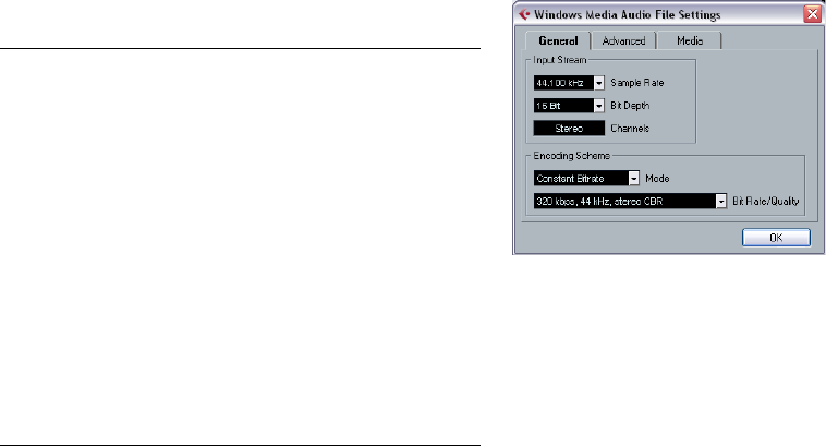
230
Export Audio Mixdown
MPEG 1 Layer 3 files
MPEG 1 Layer 3 files have the extension “.mp3”. By use of
advanced audio compression algorithms, mp3 files can be
made very small, yet maintaining good audio quality.
Apart from the Sample Rate and Bit Depth options, MPEG
1 Layer 3 files support the same settings as AIFF files in the
sections File Location, Audio Engine Output and Import into
project. The File Format settings are different, though.
For MPEG 1 Layer 3 files the following options are avail-
able in the File Format section:
Windows Media Audio files (Windows only)
This is a format developed by Microsoft Inc. Due to the ad-
vanced audio codecs and lossless compression used,
WMA files can be decreased in size with no loss of audio
quality. The files have the extension “.wma”.
When you select “Windows Media Audio File” as the file
format, you can click the “Codec Settings…” button to
open the “Windows Media Audio File Settings” window.
Windows Media Audio File Settings
Note that the configuration options may vary, depending
on the chosen output.
General tab
In the Input Stream section, you set the sample rate (44.1,
48 or 96kHz) and the bit resolution (16bit or 24bit) of the
encoded file. These should be set to match the sample rate
and bit resolution of the source material. If no value matches
that of your source material, use the closest available value
that is higher than the actual value. For example, if you’re
using 20bit source material, set the bit resolution to 24bit
rather than 16bit.
ÖThe setting in the Channels field depends on the cho-
sen output and cannot be changed manually.
The settings in the Encoding Scheme section are used for
defining the desired output from the encoder. Make set-
tings appropriate for the intended use of the file. If the file
will be downloaded or streamed on the Internet, you might
not want too high bit rates, for example. See below for de-
scriptions of the options.
Option Description
Bit Rate fader By moving this fader, you can select a bit rate for the
mp3 file. As a rule, the higher the bit rate, the better the
audio quality and the larger the file. For stereo audio,
128kBit/s is often considered to result in “good” audio
quality.
Sample Rate
pop-up On this pop-up menu you can select a Sample Rate for
the mp3 file.
High Quality
Mode option When this is activated, the encoder will use a different
resampling mode, which can give better results depend-
ing on your settings. In this mode, you cannot specify the
Sample Rate, but only the Bit Rate for the mp3 file.
Insert ID3 Tag
option This allows you to include ID3 Tag information in the
exported file.
Edit ID3 Tag
button When you click this, the ID3 Tag dialog opens, in which
you can enter information about the file. This additional
information will be embedded as text strings in the file,
and can be displayed by most mp3 playback applica-
tions.

231
Export Audio Mixdown
•Mode
The WMA encoder can use either a constant bit rate or a
variable bit rate, or it can use lossless encoding for encod-
ing to stereo. The options on this menu are as follows:
•Bit Rate/Quality
This menu allows you to set the desired bit rate. The avail-
able bit rate settings vary depending on the selected mode
and/or output channels (see above). If the Variable Bitrate
mode is used, the menu allows you to select from various
levels of quality, with 10 being the lowest and 100 the high-
est. Generally, the higher the bitrate or quality you select,
the larger the final file will be.
Advanced tab
•Dynamic Range Control
These controls allow you to define the dynamic range of
the encoded file. The dynamic range is the difference in
dB between the average loudness and the peak audio
level (the loudest sounds) of the audio. These settings af-
fect how the audio is reproduced if the file is played on a
Windows XP computer with a player from the Windows
Media series, and the “Quiet Mode” feature of the player is
activated to control the dynamic range.
The dynamic range is automatically calculated during the
encoding process, but you can specify it manually as well.
To manually specify the dynamic range, first put a check-
mark in the box to the left by clicking in it, and then enter
the desired dB values in the Peak and Average fields. You
can enter any value between 0 and -90dB. Note, how-
ever, that it is usually not recommended to change the Av-
erage value, since this affects the overall volume level of
the audio and therefore can have a negative effect on the
audio quality.
The Quiet Mode in a Windows Media player can be set to
one of three settings. Below, these settings are listed to-
gether with an explanation of how the Dynamic Range set-
tings affect them:
• Off: If Quiet Mode is off, the dynamic range settings that were
automatically calculated during the encoding will be used.
• Little Difference: If this is selected and you have not manually
changed the dynamic range settings, the peak level will be
limited to 6dB above the average level during playback. If you
have manually specified the dynamic range, the peak level will
be limited to the mean value between the peak and average
values you specified.
• Medium Difference: If this is selected and you have not manu-
ally changed the dynamic range settings, the peak level will be
limited to 12dB above the average level. If you have changed
the dynamic range, the peak level will be limited to the peak
value you specified.
Media tab
In these fields you can enter a number of text strings with
information about the file – title, author, copyright informa-
tion and a description of its contents. This information will
then be embedded in the file header and can be displayed
by some Windows Media Audio playback applications.
Mode Description
Constant Bitrate This will encode to a file with a constant bit rate (set in
the Bit Rate/Channels menu, see below). Constant bit
rate is preferably used if you want to limit the size of the
final file. The size of a file encoded with a constant bit
rate is always the bit rate times the duration of the file.
Variable Bitrate Encodes to a file with a variable bit rate, according to a
quality scale (the desired quality is set in the Bit Rate/
Quality menu, see below). When you encode with vari-
able bit rates, the bit rate fluctuates depending on the
character and intricacy of the material being encoded.
The more complex passages in the source material, the
higher the bit rate – and the larger the final file.
Lossless Encodes to a file with lossless compression.
22
Synchronization

233
Synchronization
Background
What is synchronization?
Synchronization is said to exist when you make two pieces
of equipment agree on time or tempo and position info. You
can establish synchronization between Cubase AI and a
number of other types of devices, including tape recorders
and video decks, but also MIDI devices that “play back”,
such as other sequencers, drum machines, “workstation
sequencers”, etc.
When you set up a synchronization system, you must de-
cide which unit is the master. All other devices are then
slaved to this unit, which means they will adjust their play-
back speed to the master’s.
Cubase AI as slave
When a synchronization signal is coming in to Cubase AI,
from another device, this device is the master and Cubase
AI is the slave. Cubase AI will adjust its playback to the
other device.
Cubase AI as master
When you set up Cubase AI to transmit synchronization
information to other devices, Cubase AI is the master and
the other devices are the slaves; they will adjust their play-
back to Cubase AI.
Cubase AI – both master and slave
Cubase AI is a very capable synchronization device. It can
operate as both master and slave at the same time. For ex-
ample, Cubase AI might be slaved to a tape recorder trans-
mitting timecode, while at the same time transmitting MIDI
Clock to a drum machine, acting as a master for that.
Synchronization signals
Basically there are three types of synchronization signals
for audio: timecode, MIDI clock and word clock.
Timecode (SMPTE, EBU, MTC, VITC, etc.)
Timecode appears in a number of guises. No matter which
“format” it has, it always supplies a “clock on the wall”
type of synchronization, that is, a synchronization related
to hours, minutes, seconds and two smaller units called
“frames” and “subframes”.
• LTC (SMPTE, EBU) is the audio version of timecode. This
means that it can be recorded on the audio track of an audio
or video recorder.
• VITC is the video format timecode, stored in the actual video
image.
• MTC is the MIDI version of timecode, transmitted via MIDI
cables.
• ADAT sync (Alesis) is only used with the ASIO Positioning
Protocol, see “About the ASIO Positioning Protocol (APP)” on
page 238.
For the ASIO Positioning Protocol, other high precision
timecode formats may also be supported.
Format recommendations for timecode – without ASIO
Positioning Protocol
• When using synchronizer to synchronize your system to exter-
nal timecode, the most common timecode format is MTC.
Contrary to some reports you might have heard, MTC delivers
good precision for external sync. This is due to the fact that
the operating system can “time stamp” incoming MIDI mes-
sages, which increases precision.
Format recommendations for timecode – with ASIO
Positioning Protocol
• LTC and VITC are the formats with the highest precision and
are recommended when available.
• MTC is the next best option and probably the most common
choice, since few audio hardware solutions have built-in LTC
or VITC readers. However, LTC and VITC offer even higher
precision when available.
!
For a description of the VST System Link feature
(with which you can synchronize separate computers
running Cubase AI or Nuendo for example), see
“Working with VST System Link” on page 240.

234
Synchronization
MIDI Clock
MIDI Clock is a tempo-based type of synchronization sig-
nals, i.e. it is related to the number of “beats per minute”.
MIDI Clock signals are suitable for synchronizing two de-
vices that agree on tempo, such as Cubase AI and a drum
machine.
Word Clock
Word clock is basically a replacement for the sample rate
clock (e.g. in an audio card). Word clock hence runs at
the same rate as the sample rate in the audio, 44.1kHz,
48kHz, etc.
Word clock does not contain any position information, it is
only a “simple” signal for clocking the audio at its sample
rate.
Word clock comes in many formats, analog on coaxial ca-
ble, digital as part of an S/PDIF, AES/EBU or ADAT audio
signal, etc.
Synchronizing the transport vs.
synchronizing audio
How timing is handled in a non-synchronized
system
Let’s first look at the situation where Cubase AI is not syn-
chronized to any external source:
Any digital playback system has an internal clock that ulti-
mately affects the playback speed and stability, and PC au-
dio hardware is no exception. This clock is extremely stable.
When Cubase AI is playing back with no external synchro-
nization, all playback is internally synchronized to the inter-
nal digital audio clock.
Synchronizing Cubase AI’s playback
Let’s assume now that we use external timecode synchro-
nization with Cubase AI. For example, we might synchro-
nize playback to a tape recorder.
Timecode coming from an analog tape recorder will al-
ways vary slightly in speed. Different timecode generators
and different tape recorders will also supply timecode with
slight differences in speed. In addition, the shuttling of
tape mechanisms due to overdubs and re-recordings can
cause the physical tape to wear and stretch, which affects
the speed of the timecode.
If you use a synchronizer that generates word clock and set
up Cubase AI to sync to incoming timecode, it will vary its
overall playback speed to compensate for such fluctuations
in the speed of the timecode – that’s the whole purpose of
synchronization.
What happens with the digital audio?
The fact that Cubase AI’s playback is synchronized to the
timecode does not affect the playback of the digital audio.
It still relies on the perfectly stable, built-in clock in the au-
dio hardware.
As might be expected, problems will appear when the per-
fectly stable digital audio gets related to the slightly vary-
ing speed of a system synchronized to timecode.
The playback timing of each event will not be in total ac-
cordance with the tape or the MIDI playback, since the
playback speed of the audio is determined by the digital
audio hardware’s built-in clock.
Resolving to word clock
The solution to this problem is to use one external clock for
all components in the system. One master clock is used to
derive whatever type of clock signal each component in
the system needs. For example, something called a house
clock can be used to generate sample rate clocks for the
digital audio hardware and timecode for Cubase AI. This
ensures that all components in the system use the same
reference source for their timing.
Synchronizing digital audio to external clocks running at
sample rate is often called “resolving” or “synchronizing to
word clock”.
!
MIDI Clock is not suitable as a master sync source
for an application like Cubase AI. Therefore Cubase
AI will transmit MIDI Clock signals to other devices,
but it will not receive MIDI Clock.

235
Synchronization
If you aim to perform synchronization to external signals,
we strongly recommend that you obtain proper synchroni-
zation equipment. This encompasses:
• An audio card that can be slaved to external word clock.
• A synchronizer that can read timecode (and possibly house
clock) and generate the required sync signals from that, such
as the Steinberg TimeLock Pro.
or…
• An audio system with complete built-in synchronization possi-
bilities, preferably supporting the ASIO Positioning Protocol
(see “About the ASIO Positioning Protocol (APP)” on page
238).
Using timecode without word clock
Of course, it is possible to set up a synchronization system
where you lock Cubase AI to timecode without using word
clock. However, please note that the timing of audio vs.
MIDI cannot be guaranteed and that fluctuations in speed in
the incoming timecode will not affect the playback of audio
events. This means that synchronizing to timecode may
work in the following situations:
•When the timecode was originally generated by the au-
dio card itself.
•When the source providing the timecode is extremely
stable (such as a digital video system, a digital tape re-
corder or another computer).
•When you remain synchronized to that same stable
source throughout the entire process, both while record-
ing and playing back audio.
Making basic settings and
connections
Setting the Frame Rate
The frame rate is the number of frames per second in a film
or on a video tape. However, the frame rate used varies with
the type of media (film or video), which country the video
tape has been produced in, and other circumstances.
In the Project Setup dialog are two settings for frame rates:
•The Frame Rate pop-up is automatically adjusted to the
frame rate of the incoming timecode.
There is an exception to this when you are synchronizing Cubase AI to
MIDI Timecode: If you have selected 29.97fps or 30dfps as Frame Rate in
Cubase AI, this selection will be kept, since these frame rates are not in-
cluded in the MTC format.
The following frame rates are available:
•The Display Format pop-up contains a number of for-
mats that function as the “master” setting for the display
format used in the various rulers and position displays.
Making connections
The following connections are required for external sync
via a synchronizer, including resolving of the audio card.
For details on audio card and synchronizer settings and
connections, see the manuals for these devices.
•Route the master clock signal (LTC, VITC, etc.) to an in-
put on the synchronizer.
•Connect the word clock output on the synchronizer to a
word clock input on the audio card.
•Connect the MIDI Timecode (MTC) output on the syn-
chronizer to the corresponding input on the computer.
Frame Rate Description
24 fps The traditional frame rate of 35mm film.
25 fps The frame rate used for all video and audio in Europe (EBU).
29.97 fps Straight 29.97 frames per second.
29.97 dfps “Drop frame” code running at 29.97 frames per second,
most often used in the United States of America for work
with color video.
30 fps Straight 30 frames per second. This is often used in the
United States for audio only work.
30 dfps Very rarely used.
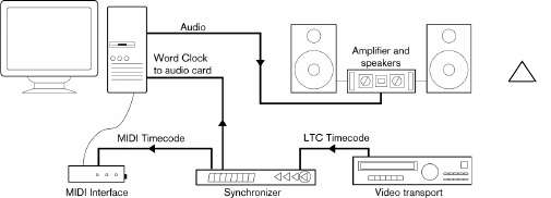
236
Synchronization
•Set up the synchronizer and make sure the frame rate
settings are in accordance with the master clock.
A typical synchronization setup
Synchronization settings
In the following sections you will find a description of how
to set up your system for the different timecode sources.
Internal Timecode
In this mode, Cubase AI is the master.
Use the “MIDI Timecode Destinations” and “MIDI Clock
Destinations” sections to specify which devices should be
slaved to Cubase AI.
Synchronizing other Equipment to Cubase AI
You may have other MIDI devices that you want to syn-
chronize to Cubase AI. There are two types of synchroni-
zation signals that Cubase AI can transmit: MIDI Clock
and MIDI Timecode.
Transmitting MIDI Clock
If you transmit MIDI Clock to a device supporting this type
of synchronization signal, the other device will follow Cu-
base AI’s tempo. The tempo setting in the other device is
of no relevance. If the device also reacts to Song Position
Pointers (which Cubase AI transmits) it will follow when
you wind, rewind and locate using the Cubase AI Trans-
port panel.
ÖMIDI Clock transport commands include “Start”, “Stop”
and “Continue”. However, some MIDI equipment (e.g.
some drum machines) do not recognize the “Continue”
command. If this is the case with your equipment, activate
the option “Always Send Start Message” in the Project
Synchronization Setup dialog (MIDI Clock Destinations).
When this is activated, only the Start command is used.
•Activate “MIDI Clock Follows Project Position” if you
want the other device to follow when you loop, jump and
locate during playback.
When this is activated, the sent MIDI Clock signals will follow the se-
quencer time and tempo position at all times.
Send MIDI Clock in Stop Mode
When the option “Send MIDI Clock in Stop Mode” in the
Project Synchronization Setup dialog (MIDI Clock Desti-
nations section) is activated, Cubase AI will send MIDI
Clock signals to the selected MIDI Clock destinations
even when Cubase AI is in Stop mode.
This is, for example, useful if you are working with a key-
board that has a built-in arpeggiator, the tempo of which
you are controlling via MIDI Clock messages. This way,
the arpeggiator will keep the right tempo even when Cu-
base AI is in Stop mode. You may also be able to use this
feature with some external drum machines, as it allows you
to play the drum patterns in the current sequencer tempo
even when Cubase AI is stopped.
•When this option is deactivated, Cubase AI will send
MIDI Clock signals to the selected MIDI Clock destina-
tions only during playback.
In this mode, you will not be able to use the above-mentioned arpeggia-
tor of your keyboard in Stop mode.
ÖKeep in mind that the MIDI Clock information always
refers to the tempo at the current project position.
Transmitting MIDI Timecode
If you transmit MIDI Timecode to a device supporting this
type of synchronization signal, the device will synchronize
time-wise to Cubase AI, that is, the time displays on Cu-
base AI’s Transport panel and on the other device will
agree. When you wind and locate Cubase AI and then ac-
tivate playback, the other device will follow from the same
position (if it has this capability and is set up for it!).
!
Please note that some external devices may not react
smoothly to these repositioning messages. Espe-
cially when working with some older devices, it may
take some time for them to synchronize accurately to
the project time.
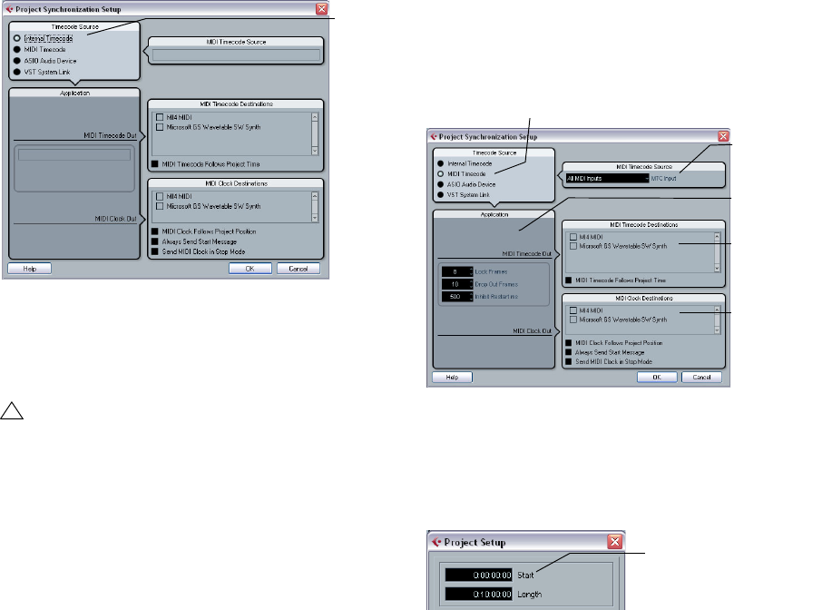
237
Synchronization
Setting Up
1. Connect the desired MIDI Outputs from Cubase AI to
the device(s) that you plan to synchronize.
2. Open the Project Synchronization Setup dialog from
the Transport menu.
3. Activate the sync outputs by using the corresponding
checkboxes.
You can output any combination of MIDI Timecode and MIDI Clock to
any combination of outputs (however, you probably do not want to send
MTC and MIDI Clock to the same output).
4. Set the other device(s) to their “external synchroniza-
tion” mode (or some other mode with a similar name) and
activate playback on them if necessary.
5. Activate playback in Cubase AI, and the other de-
vice(s) will follow.
MIDI Timecode
In this mode, Cubase AI is the slave and the timecode is
sent by the MIDI Timecode Source specified in the corre-
sponding section.
Setting up Cubase AI for external sync to timecode
1. In the Project Synchronization Setup dialog, set Time-
code Source to MIDI Timecode.
2. Use the pop-up menu in the MIDI Timecode Source
section to select an input for the timecode.
3. Close the Project Synchronization Setup dialog and
open the Project Setup dialog from the Project menu.
4. Use the Start value to set which frame on the external
device (e.g. a video tape) should correspond to the begin-
ning of the project.
5. In the dialog that appears, you are asked if you want to
keep the project content at its timecode positions. Select
“No”.
This will make all events and parts keep their positions relative to the pro-
ject start.
6. Close the Project Setup dialog.
7. On the Transport panel, activate the Sync button (or
select Use External Sync from the Transport menu).
!
Some MIDI interfaces will automatically send MIDI
Clock to all MIDI outputs, regardless of the MIDI
Clock Port selection in Cubase AI. If this is the case,
you should only select one MIDI Clock port (consult
the documentation of the MIDI Interface if in doubt).
Settings
for sync to
internal
timecode
Sync to timecode activated
Outputs for
MIDI Clock
Outputs for
MIDI
Timecode
Input port for
MIDI Timecode
Options for
incoming
timecode
Set this to the timecode
position where you want the
project to start.
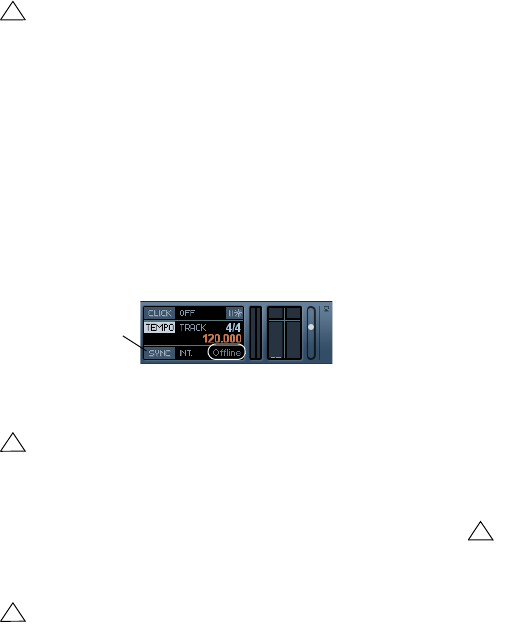
238
Synchronization
8. Start the tape (or video, or other master device) that
contains the timecode. Cubase AI starts playing when it
receives timecode with a position “higher” than or equal to
the project Start frame.
You can wind the device that sends the timecode to any
position and start from there.
You should also take a look at the Sync Options, see
“Sync Options” on page 240.
The Sync indicator
On the Transport panel you can check the status of in-
coming timecode by observing the sync indicator. It
switches between “Offline” (not waiting for sync), “Idle”
(ready for sync but no signal is coming in), and “Lock xx”
(where xx indicates the frame rate of the incoming signal).
ASIO Audio Device
In this mode, Cubase AI is the slave and the synchroniza-
tion signal can be received from another device con-
nected to a digital interface of the audio hardware.
About the ASIO Positioning Protocol (APP)
The ASIO Positioning Protocol is a technology that ex-
pands on the type of sync described above and makes
sample-accurate positioning possible.
When transferring audio digitally between devices, it is im-
portant that synchronization using word clock and time-
code is completely correlated. If not, the audio will not be
recorded at the exact intended (sample-accurate) position,
which can cause various types of problems, such as inac-
curately positioned audio material, clicks and pops, etc.
A typical situation is when transferring material from a dig-
ital multi-track tape recorder to Cubase AI (for editing)
and then back again. If you do not have sample-accurate
synchronization set up, you cannot be sure that the mate-
rial will appear in its exact original position, when trans-
ferred back to the tape recorder.
In order to take advantage of the ASIO Positioning Proto-
col, your audio hardware must be suitably equipped and
the functionality must be included in the ASIO driver for
the hardware.
An example of a system for doing sample-accurate trans-
fers would be transferring audio tracks from an Alesis
ADAT to Cubase AI. Here the ADAT will be the sync mas-
ter (though it does not necessarily have to be). It provides
both the digital audio (with an inherent word clock) and
position information (timecode) via its ADAT sync proto-
col. The master clock is generated by the ADAT itself.
Hardware and software requirements for APP
• Your computer audio hardware (in the example above, this
would be an ADAT card in your computer) must support all
the functionality required for the ASIO Positioning Protocol.
That is, it must be able to read the digital audio and the corre-
sponding position information from the external device.
• There must be an ASIO 2.0 driver for the audio hardware.
• For resolving to external timecode, the audio hardware must
have an integrated timecode reader/generator.
• For information about which audio hardware models currently
support APP, see the Steinberg web site (www.steinberg.net).
!
When the master device with the timecode is
stopped, you can use the Cubase AI transport
controls as you normally do.
!
This option is only available if your hardware is com-
patible with the ASIO Positioning Protocol.
!
The ASIO Positioning Protocol requires audio hard-
ware with specific ASIO drivers.
The Sync indicator
!
The ASIO Positioning Protocol exploits the specific
advantage of having an audio card that has an inte-
grated timecode reader. With such a card and the
ASIO Positioning Protocol, you can achieve constant
sample-accurate synchronization between the audio
source and Cubase AI.
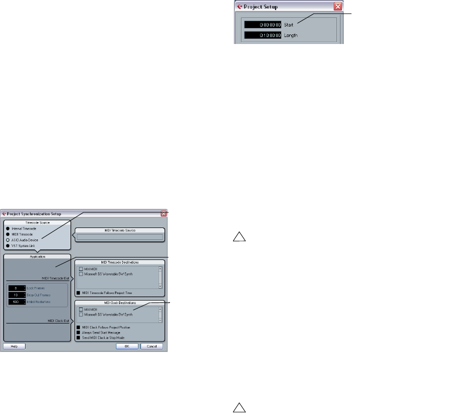
239
Synchronization
Setting up the audio card for external synchronization
1. Open the Device Setup dialog from the Devices menu
and, on the VST Audio System page, select the name of
your audio interface.
2. Click the Control Panel button to open the card’s pro-
prietary setup dialog.
If this card is accessed via a special ASIO driver (as opposed to Di-
rectX or the Generic Low Latency ASIO Driver), this dialog is provided
by the card, not by Cubase AI. Hence the settings vary with the card
brand and model.
3. Adjust the settings as recommended by the card man-
ufacturer, then close the dialog.
The dialog may also contain various diagnostic tools that allow you to
verify for example whether word clock is arriving correctly.
4. From the Clock Source pop-up, select the input to
which you routed the word clock signal.
This pop-up menu may not be used if you selected an input in the Con-
trol Panel dialog instead.
You can now set up the synchronization:
1. Open the Project Synchronization Setup dialog and
set the Timecode Source to “ASIO Audio Device”.
2. Make the necessary settings in the dialog.
For information on the different sections, click the Help button in the dialog.
3. Close the Project Synchronization Setup dialog.
4. Open the Project Setup dialog from the Project menu
and use the Start value to set which frame on the external
device (e.g. a video tape) should correspond to the begin-
ning of the project.
5. A message appears, asking you whether you want to
keep the project content at its timecode positions. Select
“No”.
This will make all events and parts keep their positions relative to the pro-
ject start.
6. Close the Project Setup dialog.
7. On the Transport panel, activate the Sync button (or
select “Use External Sync” from the Transport menu).
8. Start the tape (or video, or other master device) that
contains the timecode. Cubase AI starts playing when it
receives timecode with a position “higher” than or equal to
the project Start frame.
You can wind the device that sends the timecode to any
position and start from there.
You should also take a look at the Sync Options, see
“Sync Options” on page 240.
The Sync indicator
On the Transport panel you can check the status of incom-
ing timecode by observing the sync indicator. It switches
between “Offline” (not waiting for sync), “Idle” (ready for
sync but no signal is coming in), and “Lock xx” (where xx
indicates the frame rate of the incoming signal).
VST System Link
The ASIO
Audio Device
is selected as
Timecode
Source.
Outputs for
MIDI Clock
Options for
incoming
timecode
!
When the master device is stopped, you can use the
Cubase AI transport controls as you normally do,
when it is not synchronized.
!
For a description of the VST System Link feature
(with which you can synchronize separate computers
running Cubase AI or Nuendo for example) see
“Working with VST System Link” on page 240.
Set this to the timecode
position where you want the
project to start.
240
Synchronization
Sync Options
The following Sync options are available in the Project
Synchronization Setup dialog:
Lock Frames
Using this field you can set how many frames of “correct”
timecode Cubase AI should receive before attempting to
“lock” (synchronize) to incoming timecode. If you have an
external tape transport with a very short start-up time, you
could try lowering this number to make lock-up even faster
than it already is.
Drop Out Frames
On an analog tape with timecode, dropouts may occur. If
a drop-out is very long, Cubase AI may (temporarily) stop.
In the Drop Out Frames field you can set how long a drop-
out (in frames) should be tolerated until Cubase AI de-
cides that the tape is not good enough to synchronize to.
If you have a very stable timecode source, you may lower
this number to make Cubase AI stop more swiftly after the
tape recorder has been stopped.
Inhibit Restart
Some synchronizers will still transmit MIDI Timecode for a
short period after an external tape machine has been
stopped. These extra frames of timecode can sometimes
cause Cubase AI to restart suddenly. Inhibit Restart allows
you to control the amount of time in milliseconds that Cu-
base AI will wait to restart (ignoring incoming MTC) once it
has stopped.
Working with VST System Link
VST System Link is a network system for digital audio that
allows you to have several computers working together in
one large system. Unlike conventional networks it does not
require Ethernet cards, hubs, or CAT-5 cables; instead it
uses the kind of digital audio hardware and cables you
probably already possess in your studio.
VST System Link has been designed to be simple to set
up and operate, yet give enormous flexibility and perfor-
mance gains in use. It is capable of linking computers in a
“ring” network (the System Link signal is passed from one
machine to the next, and eventually returns to the first ma-
chine). VST System Link can send its networking signal
over any type of digital audio cable, including S/PDIF,
ADAT, TDIF, or AES, as long as each computer in the
system is equipped with a suitable ASIO compatible audio
interface.
Linking up two or more computers gives you vast possibil-
ities:
• Dedicate one computer to running VST instruments while re-
cording audio tracks on another.
• If you need lots of audio tracks, you may simply add tracks on
another computer.
• You could have one computer serve as a “virtual effect rack”,
running CPU-intensive send effect plug-ins only.
Since you can use VST System Link to connect different
VST System Link applications on different platforms, you
can take advantage of effect plug-ins and VST instru-
ments that are specific to certain programs or platforms.
Preparations
Requirements
The following equipment is required for VST System Link
operation:
•Two or more computers.
These can be of the same type or use different operating systems – it does
not matter. For example, you can link an Intel-based PC to an Apple Macin-
tosh without problems.
•Each computer must have audio hardware with specific
ASIO drivers, installed and working.
•The audio hardware must have digital inputs and outputs.
Of course, to be able to connect the computers, the digital connections
must be compatible (i.e. the same digital formats and connection types
must be available).
•At least one digital audio cable for each computer in the
network.
•A VST System Link host application installed on each
computer.
Any VST System Link applications can connect to each other.
Additionally, we recommend that you use a KVM switchbox.

241
Synchronization
Using a KVM switchbox
If you want to set up a multi-computer network, or even a
small network in a limited space, it is a good idea to invest
in a KVM (Keyboard, Video, Mouse) switchbox. With one
of these you can use the same keyboard, monitor, and
mouse to control each computer in the system, and switch
between computers very rapidly. KVM switchboxes are
not too expensive, and very easy to set up and operate. If
you decide not to go this route, the network will function
just the same, but you may end up doing a lot of jumping
from one machine to the other while setting up!
Making connections
Below, we assume that you are connecting two comput-
ers. Should you have more than two computers, it is still
best to start with two and add the others one by one once
the system is working – this makes troubleshooting easier
if you run into problems. For two computers, you will need
two digital audio cables, one in each direction:
1. Use the first digital audio cable to connect digital out-
put of computer 1 with the digital input of computer 2.
2. Use the other cable to connect the digital output of
computer 2 with the digital input of computer 1.
•If a card has more than one set of inputs and outputs,
choose whichever one that suits you – for simplicity usu-
ally the first set is best.
Synchronization
Before you proceed, you need to make sure that the clock
signals on your ASIO cards are synchronized correctly.
This is essential when cabling any kind of digital audio
system, not just VST System Link.
The Clock Mode or Sync Mode is set up in the ASIO con-
trol panel of the audio hardware. In Cubase AI, you pro-
ceed as follows:
1. Pull down the Devices menu and open the Device Set-
up dialog.
2. On the VST Audio System page, select your audio in-
terface from the “ASIO Driver” pop-up menu.
The name of the audio interface now appears as a subentry to the VST
Audio System entry in the Devices list.
3. Select your audio interface in the Devices list to the left.
4. Click the Control Panel button.
The ASIO control panel appears.
5. Open the ASIO control panel on the other computer
as well.
If you are using another VST System Link host application on that com-
puter, check its documentation for details on how to open the ASIO con-
trol panel.
6. Now, you need to make sure that one audio card is set
to be the Clock Master, and all the other cards are set to
listen for the clock signal coming from the Clock Master,
i.e. they must be Clock Slaves.
The naming and procedure for this differs depending on the audio hard-
ware – consult its documentation if required. If you are using Steinberg
Nuendo ASIO hardware, all cards default to the “AutoSync” setting – in
this case you must set one of the cards (and only one) to “Master” in the
Clock Mode section of the control panel.
•Typically, the ASIO control panel for an audio card con-
tains some indication of whether the card receives a proper
sync signal or not, and the sample rate of that signal.
This is a good indication that you have connected the cards and set up
clock sync properly. Check your audio hardware’s documentation for de-
tails.
The only exception to this procedure is if you are using an
external clock – which could be from a digital mixing desk
or special Word Clock synchronizer for example. If so, you
must leave all your ASIO cards in Clock Slave or AutoSync
!
All digital audio cables by definition always carry a
clock signal as well as audio signals, so you do not
have to use a special Word Clock input and output
for this (although you may find that you get a slightly
more stable audio system if you do, especially when
using multiple computers).
!
It is very important that one and only one card is the
clock master, otherwise the network cannot function
correctly. Once you have set this up, all the other
cards in the network will take their clock signal from
this card automatically.
242
Synchronization
mode, and make sure that each of them is listening for the
signal coming from the synchronizer, usually passed
through your ADAT cables or Word Clock connectors in a
daisy chain fashion.
VST System Link and latency
The general definition of latency is the amount of time it
takes any system to respond to whatever messages are
sent to it. For example, if your system’s latency is high and
you play VST instruments in realtime, you will get a notice-
able delay between when you press a key and when you
hear the sound of the VST instrument. Nowadays, most
ASIO-compatible audio cards are capable of operating
with very low latencies. Also, all VST applications are de-
signed to compensate for latency during playback, making
the playback timing tight.
However, the latency time of a VST System Link network
is the total latency of all the ASIO cards in the system
added together. Therefore it is extra important to minimize
the latency times for each computer in the network.
ÖThe latency does not affect the synchronization – it is
always perfectly in time. But it can affect the time it takes
to send and receive MIDI and audio signals, or make the
system seem sluggish.
To adjust the latency of a system, you adjust the size of the
buffers in the ASIO control panel – the lower the buffer
size, the lower the latency. It is best to keep to fairly low la-
tencies (buffer sizes) if your system can handle it – about
12ms or less is usually a good idea.
Setting up your software
Now it is time to set up your programs. The procedures
below describe how to set things up in Cubase AI. If you
are using another program on the other computer, please
refer to its documentation.
Setting the sample rate
The projects in both programs must be set to use the
same sample rate. Select “Project Setup…” from the Pro-
ject menu and make sure the sample rate is the same in
both systems.
Streaming digital audio between applications
1. Create input and output busses in both applications
and route these to the digital inputs and outputs.
The number and configuration of the busses depends on your audio
hardware and on your needs. If you have a system with eight digital i/o
channels (such as an ADAT connection), you could create several stereo
or mono busses, or any combination you need. The important thing is
that you should have the same configuration in both applications – if you
have four stereo output busses on computer 1, you want four stereo in-
put busses on computer 2, etc.
2. Set things up so that computer 1 plays back some
audio.
You could for example import an audio file and play it back in Cycle mode.
3. In the Inspector or Mixer, make sure the playing audio
channel is routed to one of the digital output busses you
set up.
4. In computer 2, open the Mixer and locate the corre-
sponding digital input bus.
The audio being played back should now “appear” in the program run-
ning on computer 2. You should see the input bus level meters moving.
5. Reverse this procedure so that computer 2 plays back
and computer 1 “listens”.
Now you have verified that the digital connection works as
it should.
ÖFrom this point on in this chapter, we refer to the bus-
ses connected to the digital inputs and outputs as “VST
System Link busses”.
Settings for the audio hardware
When you send VST System Link data between comput-
ers, it is important that the digital information is not
changed in any way between the programs. Therefore,
you should open the control panel (or additional applica-
tion) for your audio hardware and make sure that the fol-
lowing conditions are met:
•If there are additional “format settings” for the digital
ports that you use for VST System Link data, make sure
these are turned off.
For example, if you are using an S/PDIF connection for VST System Link,
make sure that “Professional format”, Emphasis and Dithering are turned
off.
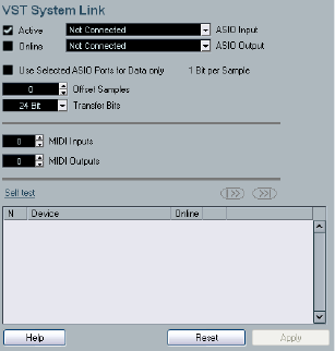
243
Synchronization
•If your audio hardware has a mixer application allowing
you to adjust the levels of digital inputs and outputs, make
sure that this mixer is disabled or that the levels for the
VST System Link channels are set to ± 0dB.
•Similarly, make sure no other forms of DSP (pan, ef-
fects, etc.) are applied to the VST System Link signal.
Notes for Hammerfall DSP users
If you are using RME Audio Hammerfall DSP audio hard-
ware, the Totalmix function allows for extremely complex
signal routing and mixing in the audio hardware. This can
in some situations lead to “signal loops” in which case the
VST System Link will not work. If you want to make abso-
lutely sure this will not cause any problems, select the de-
fault or “plain” preset for the Totalmix function.
Activating VST System Link
Before you proceed, you need to make sure that VST Sys-
tem Link is set as Timecode Source in the Project Syn-
chronization Setup dialog and that the desired Sync
options are activated, see “Sync Options” on page 240.
After setting up the inputs and outputs, you now need to
define which input/output should carry the actual VST
System Link information.
The System Link networking signal is carried on only one
bit of one channel. This means that if you have an ADAT
based system which normally carries eight channels of
24-bit audio, once you activate VST System Link you will
have seven channels of 24-bit audio and one channel of
23-bit audio (the least significant bit of this last channel
will be used for networking). In practice this makes no dis-
cernible difference to the audio quality, since you will still
have around 138dB headroom on this channel.
To set things up, open the VST System Link panel:
1. Open the Device Setup dialog on the Devices menu.
2. Select VST System Link in the Devices list to the left.
3. Use the ASIO Input and ASIO Output pop-up menus
to define which channel should be the networking channel
(and thus become a 23-bit audio channel, in our example).
Quite often you will be able to leave these pop-ups the way they are.
4. Click the Active checkbox at the top of the panel.
5. Repeat the steps above for every computer on the
network.
As the computers are made active, you should see the
small Sending and Receiving indicators flashing on each
active computer, and the name of each computer should
appear in the list at the bottom of the pane. Each computer
is assigned a random number – do not worry about this, it is
just so the network knows internally which one is which.
•You can double-click on the name in bold (which is the
name of the computer you are currently working on) and
set it to whatever other name you wish.
This name will appear in the System Link window of every computer on
the network.
ÖIf you do not see the name of each computer appear-
ing once you have made it active, you may have to check
your settings.
Go through the procedure above again and make sure that all ASIO
cards are listening to the digital clock signals correctly, and that each
computer has the correct inputs and outputs assigned to the System
Link network.
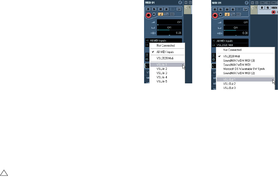
244
Synchronization
Putting the network online
After each computer’s name you will see whether it is online
or not. When a computer is online, it will receive transport
and timecode signals, and its sequencer application can be
started and stopped by remote control. If it is off-line, it can
only be started from its own keyboard – it is effectively an
independent machine, although it is still on the network.
ÖNote that any computer can control any and all of the
others – VST System Link is a peer-to-peer network and
there is no absolute “master” computer.
However, most users do like to think of one machine as the master (in a
one person/two computer network, this would be the machine you actu-
ally sit behind most of the time).
For now, let’s put all computers online:
1. Activate the Online checkbox in the VST System Link
panel for all computers.
2. Check that the system is working by pressing Play on
one computer – all computers should start almost instantly
and play perfectly in time, with sample-accurate precision.
•The Offset setting allows you to adjust whether one ma-
chine will play back slightly ahead or behind the rest.
This is normally not needed, but occasionally with some hardware you
may find that the lock is a few samples out. In that case you can adjust
the lock with the Offset value. For now, leave it set to 0 – it will most likely
be what you want.
•The Transfer Bits setting allows you to specify whether
you want to transfer 24 or 16 bits. This allows you to use
older audio cards which do not support transfer of 24 bits.
VST System Link sends and understands all transport
commands, so you can play, stop, fast forward, rewind,
etc. the entire network from one computer without a prob-
lem – try it! If you jump to a locator point on one machine,
all other machines will also instantly jump to that locator
point. You can even scrub on one computer and have the
video and audio on another computer actually scrub right
along with you.
Using MIDI
As well as supplying transport and sync control, VST Sys-
tem Link also supplies up to 16 MIDI ports, each with 16
channels. You set this up as follows:
1. Use the MIDI Inputs and Outputs value boxes to spec-
ify the number of MIDI ports you need.
The default value is 0 MIDI In and 0 MIDI Out ports.
2. Create a MIDI track in the Project window and open
the Inspector (top section).
3. If you now pull down the Input or Output Routing pop-
up menu, you will find the specified System Link ports
added to the list of MIDI Inputs and Outputs.
This allows you to route MIDI tracks to VST instruments
running on another computer, as described in the applica-
tion examples (see “Using one computer for VST instru-
ments” on page 246).
The “Use Selected ASIO Ports for Data only” setting
If you are sending huge amounts of MIDI data at once,
there is a small possibility that you might run out of band-
width on your VST System Link network. This will manifest
itself by notes “choking” or timing becoming erratic.
If this happens, you can devote more bandwidth to MIDI
by activating “Use Selected ASIO Ports for Data only” in
the VST System Link Setup panel. When this is activated,
the VST System Link information will be sent on the entire
channel instead of just one bit, more than enough for all
the MIDI you could ever hope to use. The downside is that
!
Make sure that all computers have their tempos set
to the same value, otherwise your synchronization
will be seriously skewed.
245
Synchronization
you can no longer use this ASIO channel for audio transfer
(do not connect it to a speaker!), thus leaving you only 7
channels of audio in our ADAT cable example. Depending
on how you work this might be a reasonable compromise.
Hearing the network audio
If you are using an external mixing desk, hearing your audio
really is not an issue – just plug the outputs of each com-
puter into the desired channels on the external mixing desk,
press Play on one of the computers, and you're good to go.
However, many people prefer to mix internally inside the
computer and just use a desk for monitoring (or maybe not
use any external mixer at all). In this case you will need to
select one computer to be your “main mix computer” and
send the audio from your other computers into this.
In the following example, we assume you are using two
computers, with computer 1 as your main mix computer
and computer 2 running two additional stereo audio
tracks, an FX channel track with a reverb plug-in and a
VST instrument plug-in with stereo outputs.
1. First you want to set things up so that you can listen to
the audio playback from computer 1.
In other words, you need an unused set of outputs, e.g. an analog stereo
output, connected to your monitoring equipment.
2. Go to computer 2 and route each of the two audio
tracks to a separate output bus.
These should be busses connected to the digital outputs – let’s call
them Bus 1 and 2.
3. Route the FX channel track to another VST System Link
bus (Bus 3).
4. Route the VST instrument channel to yet another bus
(Bus 4).
5. Go back to computer 1 and check the corresponding
four VST System Link input busses.
If you start playback on computer 2, the audio should “appear” on the input
busses on computer 1. However, to mix these audio sources you need ac-
tual mixer channels.
6. Add four new stereo audio tracks on computer 1 and
route these to the output bus you use for listening, e.g. to
the analog stereo outputs.
7. For each of the audio tracks, select one of the four in-
put busses.
Now, each computer 2 bus is routed to a separate audio channel on
computer 1.
8. Activate monitoring for the four tracks.
If you now start playback, the audio from computer 2 will
be sent “live” to the new tracks on computer 1, allowing
you to hear them together with any tracks you play back
on computer 1.
For more information about Monitoring, see “About moni-
toring” on page 13.
Adding more tracks
What if you have more audio tracks than you have VST
System Link busses (physical outputs)? Then you just use
the computer 2 mixer as a submixer: Route several audio
channels to the same output bus and adjust the output
bus level if needed.
Note also that if your audio cards have multiple sets of in-
put and output connections you can link up multiple ADAT
cables and send audio via any of the busses on any of the
cables.
Internal mixing and latency
One problem with mixing inside the computer is the latency
issue we mentioned earlier. The VST engine always com-
pensates for record latencies, but if you are monitoring
through computer 1 you will hear a processing delay while
you listen to signals coming from your other computers (not
on your recording!). If your audio card in computer 1 sup-
ports ASIO Direct Monitoring you should definitely turn this
on – you can find the setting in the VST Audio System De-
vice Setup panel (see “ASIO Direct Monitoring” on page
53). Most modern ASIO cards support this function. If
yours does not you may want to change the Offset value in
the VST System Link Setup panel to compensate for any la-
tency issues.
Setting up a larger network
This is not much more difficult than a two computer net-
work. The main thing to remember is that VST System Link
is a daisy chain system. In other words, the output of com-
puter 1 goes to the input of computer 2, the output of
computer 2 goes to the input of computer 3, and so on
around the chain. The output of the last computer in the
chain must always go back into the input of computer 1, to
complete the ring.
246
Synchronization
Once you have done this, the transmission of all the trans-
port, sync, and MIDI information to the whole network is
handled pretty much automatically. However, where you
may run into confusion in a large network is in the trans-
mission of audio signals back to a central mix computer.
If you have lots of hardware inputs and outputs on your
ASIO cards you do not have to send audio via the chain at
all, but can transmit it directly to the master mix computer
via one or more of its other hardware Inputs. For example, if
you have a Nuendo Digiset interface or 9652 card on com-
puter 1 you could use ADAT cable 1 for networking, ADAT
cable 2 as a direct audio input from computer 2, and ADAT
cable 3 as a direct audio input from computer 3.
You can also transmit audio via the ring system if you do
not have enough hardware I/Os for direct audio transmis-
sion. For example, in a four computer scenario you could
send audio from computer 2 into a channel in the mixer in
computer 3, and from there to a channel in the mixer in
computer 4, and from there back to the master mixer in
computer 1. This can certainly be tricky to set up, so gen-
erally it is recommended that if you want to set up a com-
plex network, you should make sure to use ASIO cards
with at least three separate digital I/Os.
Application examples
Using one computer for VST instruments
In this example, one computer will be used as main record
and playback machine, and another computer as a virtual
synth rack.
1. Record a MIDI track into computer 1.
2. Once you have finished recording, route the MIDI out-
put of that track to System Link MIDI port 1.
3. Now go to computer 2, open up the VST Instrument
rack and assign an instrument to the first slot in the rack.
4. Route the VST Instrument channel to the desired out-
put bus.
If you are using computer 1 as your main mixing computer, this would be
one of the VST System Link output busses, connected to computer 1.
5. Create a new MIDI track in the Project window of
computer 2, and assign the MIDI output of the track to the
VST Instrument you created.
6. Assign the MIDI input of the track to be VST System
Link port 1.
Now, the MIDI track on computer 1 is routed to the MIDI track on com-
puter 2, which in turn is routed to the VST Instrument.
7. Now activate monitoring for the MIDI track on com-
puter 2, so that it will listen and respond to any MIDI com-
mands coming in.
In Cubase AI, you would click the Monitor button in the Track list or In-
spector.
8. Start Playback on computer 1.
It will now send the MIDI information on the track to the VST Instrument
loaded on computer 2.
Even with a slow computer you should be able to stack a
whole bunch of extra VST Instruments this way, expanding
your sound palette considerably. Do not forget that VST
System Link MIDI is also sample-accurate, and thus has
much tighter timing than any hardware MIDI interface ever
invented!
Creating a virtual effect rack
The effect sends for an audio channel in Cubase AI can
either be routed to an FX channel track or to any activated
Group or output bus. This allows you to use a separate
computer as a “virtual effect rack”, by setting things up in
the following way:
1. Go to computer 2 (the machine you will use as effect
rack) and add a new stereo audio track.
You cannot use an FX channel track in this case, since the track must
have an audio input.
2. Add the desired effect as an insert effect for the track.
Let’s say you add a high-quality reverb plug-in.
3. In the Inspector, select one of the VST System Link
busses as input for the audio track.
You want to use a separate System Link bus, which will only be used for
this purpose.
4. Route the channel to the desired output bus.
If you are using computer 1 as your main mixing computer, this would be
one of the VST System Link output busses, connected to computer 1.
5. Activate monitoring for the track.
6. Now, go back to computer 1 and select a track to
which you want to add some reverb.
7. Bring up the effect sends for the track in the Inspector.
247
Synchronization
8. Open the Send Routing pop-up menu for one of the
sends, and select the VST System Link bus assigned to
the reverb in step 3.
9. Use the Send slider to adjust the amount of effect as
usual.
The signal will be sent to the track on computer 2 and pro-
cessed through its insert effect, without using any proces-
sor power on computer 1.
You can repeat the steps above to add more effects to the
“virtual effect rack”. The number of effects available this way
is only limited by the number of ports used in the VST Sys-
tem Link connection (and of course by the performance of
computer 2, but given that it will not have to handle any re-
cording or playback, you should be able to use quite a lot of
effects).
Getting extra audio tracks
All computers on a VST System Link network are locked
with sample-accuracy. Therefore, if you find that the hard
drive on one computer is not fast enough to run as many
audio tracks as you need, you can record new tracks on
one of the other computers instead. This would create a
“virtual RAID system”, with several disks all operating to-
gether. All tracks will remain locked together just as tightly
as if they were all running on the same machine. This
means that you effectively have an unlimited track count!
Need another 100 tracks? Just add another computer.
23
Video
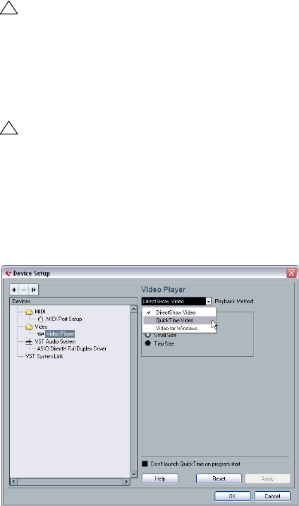
249
Video
Background
Cubase AI plays back video films in a number of formats.
Under Windows, video playback can be done using one
of three playback engines: Video for Windows, DirectS-
how or QuickTime 7.1. This ensures compatibility with as
wide a range of video files as possible. The following file
formats are supported: AVI, QuickTime and MPEG.
Under Mac OS X, QuickTime is always used as playback
engine. QuickTime supports the following video file for-
mats: AVI, MPEG, QuickTime and DV.
There are two ways to play back video:
•Without any special hardware.
See “Playing back video without any hardware” on page 250.
•Using video hardware that, for example, connects to an
external monitor.
See “Playing back video file using video hardware” on page 251.
Before you start
When working on a project involving a video file, there are
several points to bear in mind:
Have you selected the right playback engine?
(Windows only)
The playback engine is used not only for playback of the
video file, but also to provide file information in the Pool and
in the Import Video dialog. Therefore, to make sure that you
have chosen the right playback engine for a particular type
of video file, check the file information displayed in the Im-
port Video dialog or the Pool prior to trying to import or
playing back the file.
When this information reads “0x0 pixel”, “0.000 s” and “0
Frames”, the video file is either corrupt, or the format is not
supported by the codecs available to the selected video
playback engine. You will either have to change the video
playback engine, or install the required codec.
About the QuickTime video playback engine
In Cubase AI for Windows, you select a playback engine
in the Device Setup–Video Player page:
•Generally, you can expect most Windows hardware to
work with DirectShow.
On a Windows system, the DirectShow and Video for Windows players
are provided by the operating system, so you do not have to install any
additional software.
•Under Windows, QuickTime 7.1 must be installed on
your computer for QuickTime playback to be available.
There is a freeware version (a QuickTime installer is included on the Cu-
base AI DVD if required, or you can download it from www.quicktime.com)
and a “pro” version, which offers additional video cutting options. The en-
gine is the same in both versions, so for mere playback in Cubase AI there
is no need to purchase the “pro” version.
!
Trying to import or play back a file not supported by
the selected video playback engine leads to unpre-
dictable results – if no information on the number of
frames, the length and the pixel resolution is available
in the Import Video dialog or the Pool, you cannot im-
port/play this file properly with this particular video
playback engine.
!
You can change the video playback engine in the
Device Setup dialog. After having done so, make
sure to remove any previously imported video file
from the Pool first, and re-import it.
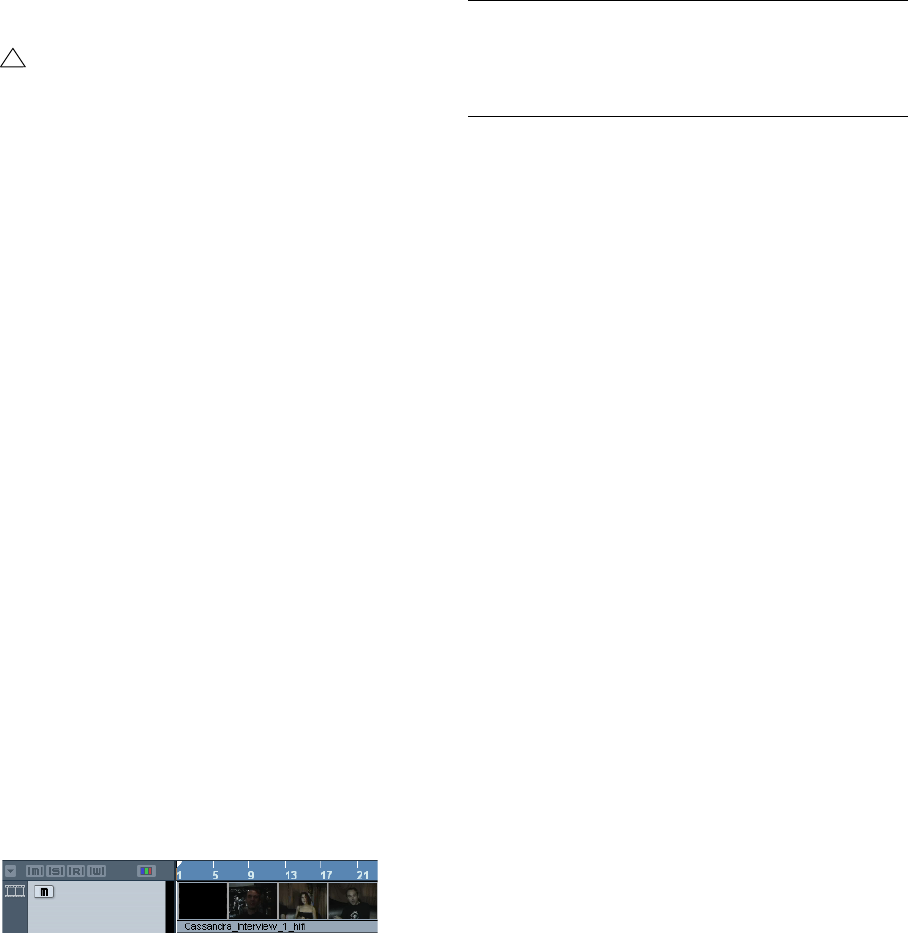
250
Video
•Under Mac OS X, only the QuickTime playback engine
is available, supporting the formats AVI, MPEG, Quick-
Time and DV. If your system has a FireWire port, there is
also a FireWire option – see below.
Video quality in QuickTime
When you are using QuickTime as your video playback
engine, you can select “High Quality” from the Video win-
dow context-menu, or “Use high-quality video settings
when available” in the Device Setup dialog, Video Player
page, in the Video Properties section for QuickTime.
•When your QuickTime video was recorded with the cor-
responding quality settings, selecting the “Use high-qual-
ity video settings when available” or the “High Quality”
option will make the video display sharper and smoother.
Note that this will also lead to increased processor load.
Video playback preferences
In the Preferences (Event Display–Video page), there are
two options for video playback:
•Show Video Thumbnails.
When this is activated, thumbnail frames of the video contents are shown
in the track.
•Video Cache Size.
This determines how much memory is available for video thumbnails. If you
have long video clips and/or work with a large zoom factor (so that a lot of
frames are shown in the thumbnails), you may have to raise this value.
Playing back a video file
Video files are displayed as events/clips on the video
track, with thumbnails representing the frames in the film
(if the option Show Video Thumbnails is activated in the
Preferences, see above).
A video event on a video track
In the Track list and Inspector, you will find the following
controls for video tracks:
To view the video on the computer screen (as opposed to
on an external monitor, see below), proceed as follows:
•If you’re running Mac OS X, open the Device Setup dia-
log from the Devices menu, click “Video Player” in the list
and make sure “Onscreen Window” is selected in the
Video Output section of the dialog.
•Under Windows, either pull down the Devices menu
and select Video, or use a key command – by default [F8],
or double-click the video clip.
A video window appears. In Stop mode, this displays the video frame at
the project cursor position.
The video will be played back together with any other
events in the Project window as usual.
Playing back video without any hardware
•For the DirectShow video player, open the Device Setup
dialog from the Devices menu, click Video Player in the De-
vices list and use the buttons in the Video Properties sec-
tion to select a size or right-click in the video window to
switch to full screen. Right-click again to exit full screen.
•For the QuickTime player (Windows and Mac), you can
drag the borders, just like resizing other windows. You can
also right-click in the video window to open the Video win-
dow context menu and select one of the Size options.
There is also a Full Screen Mode available in the menu.
Right-click again or press the [Esc] key on your computer
keyboard to exit full screen mode.
ÖPlaying back video on your computer screen puts a limit
on the size of the video window as well as the image quality.
!
QuickTime as a video playback engine is available
only if you have QuickTime 7.1 (or higher) installed
on your computer. If you do not have QuickTime, or if
a version lower than 7.1 is installed, this option will
not be available in Cubase AI.
Button Description
Mute Video When this is activated, video playback will be stopped,
but playback of any other events in the project will con-
tinue (to decrease the processor load). You may have to
use the Track Controls Settings dialog to make this but-
ton visible in the Track list.
251
Video
Playing back video file using video hardware
Under Windows, multi-head graphics cards that support
overlay functionality can be used to display the video pic-
ture on an external TV or computer monitor in full screen
mode. The manufacturers nVIDIA and Matrox have work-
ing (and tested) solutions available. Check the card’s do-
cumentation for information on how it handles video
output and how to set it up for multi-monitor display.
For Apple computers equipped with a FireWire port, you
can easily connect external video hardware via this, as
OS X has built-in video support for the most common for-
mats (NTSC/PAL/DVCPRO). FireWire is capable of high
data-transfer speed and is the most common standard for
communicating with video-related peripheral equipment.
To play back a video file via hardware connected to the
FireWire port, select “FireWire” in the Outputs pop-up of
the Device Setup–Video Player dialog. When FireWire is
selected as output, a number of format options appear on
the Format pop-up, allowing you to select between vari-
ous video formats and resolutions.
Operations
Importing a video file
Video files are imported in the same manner as audio files.
•By using the File menu (Import–Video File).
•By using drag and drop from the Windows Explorer/
Mac OS Finder or the Pool.
This requires that a video track has been added to the Project and that
you drop the video file onto this track.
•By importing the file to the Pool first and then dragging
it into the Project window (see the chapter “The Pool” on
page 143 for details).
Please note the following:
• You can only have one video track in each project. The Video
track is added like other tracks in the Project window by using
the Add Track submenu on the Project menu. If a project does
not contain a video track when you import a video file via File–
Import–Video file, this is added automatically.
• All video files on the track must be of the same size and com-
pression format.
Video import preferences
In the Preferences dialog (Editing–Video page), you will
find one option that affects the import of video files:
•Generate Thumbnail Cache on Import Video File
When this is activated, a thumbnail cache file will be created automati-
cally when you import a video file. This is handy, as a cache file will also
be created when you import a video file using drag and drop.
Advantage of thumbnail cache files
ÖTo display video thumbnails in the Project window, the
option “Show Video Thumbnails” has to be activated in
the Preferences dialog (Event Display–Video page).
When working with video in Cubase AI, video files are dis-
played as events/clips on the video track with thumbnails
representing the frames in the film. These are calculated in
realtime, i.e. they have to be redrawn during scrolling or
moving. As this consumes quite a lot of processor power,
reaction sometimes may be sluggish. To remedy this, you
can generate a thumbnail cache file.
The cache file is used in situations where the processor
load is very high and the correct redrawing or realtime cal-
culation might use system resources necessary for editing
or processing. When the cache file is used and you zoom
in on the thumbnails, you will see that they are in a lower
resolution, i.e. the pictures are not as clean as when they
are calculated. When the processes that rely heavily on the
computer CPU are finished, the frames will be automati-
cally recalculated, i.e. the program automatically switches
between realtime calculation of the pictures and using the
cache file.
The generated thumbnail cache file will be stored in the
same folder as the video file and will get the name of the
file with the suffix “.videocache”.
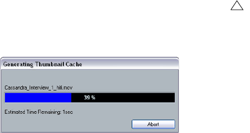
252
Video
Generating thumbnail cache files during video import
A thumbnail cache file will be created automatically before
the file is inserted in the Project window, if you activated
“Generate Thumbnail Cache on Import Video File” in the
Preferences (Editing–Video page).
A window will be displayed, showing you the progress
and the estimated time for the process.
The thumbnail cache file is being created.
After the cache file is created, the window will be closed
and the video clip is inserted as usual. When you now
start video playback and perform processor consuming
operations, the thumbnail file is used to display the video
frames in the Project window. When enough processor
power is available, the “real” calculated thumbnail frames
are displayed again.
Generating thumbnail cache files from within the Pool
When you have video files without thumbnail cache files
(e.g. if you did not create a thumbnail cache file during im-
port), you always have the possibility to generate the
thumbnail cache file at a later stage. This is done from
within the Pool.
Proceed as follows:
1. Open the Pool window and locate the video file you
want to create a thumbnail cache file for.
2. Right-click the file to open the context menu and se-
lect “Generate Thumbnail Cache”, or select “Generate
Thumbnail Cache” from the Media menu.
Just as when creating the file during import, the status window opens
(see above).
After the file is created, the window will be closed and the
thumbnail cache file is used when necessary, i.e. under
high load.
Editing a video file
Video clips are played back by events just as audio clips
are. You can use all the basic editing operations on video
events, just as with audio events. The following operations
are not possible on the video track:
•Drawing, Gluing, and Scrubbing.
Note that when you activate the Mute button for a video track, the video
playback will be stopped, but playback of any other Project events will
continue, see below.
•The video track has no editor and does not make use of
parts.
•Cubase AI allows you to cut, copy, paste and trim video
events, i.e. your video track may contain more than one
video event. However, when using the DirectShow video
player (Windows only), you may find that only the first event
on the video track is played back correctly. In such a case
make sure that the video track contains no more than one
video event.
•Under Windows, you may find that you are unable to
edit a video file copied from a CD. This is because files
copied from CD are write protected by default. Right-click
the file, and deactivate the “Read-Only” option in the File
Properties dialog.
•When you have a video file in a format not supported by
Cubase AI, use an external application to convert the file
to a format that Cubase AI can import.
!
Please note that the cache file will not be automati-
cally updated if a video file is edited. Whenever you
change a video file (e.g. in a video editing applica-
tion), you need to create a new thumbnail cache file
manually, as described above. (To refresh the “real”
thumbnails of an edited video file, resize the video
track so that they are calculated again.)
24
File handling
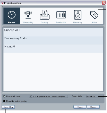
254
File handling
Working with Projects
New Project
With the “New Project…” command on the File menu you
open the Project Assistant dialog which allows you to ac-
cess recently opened projects and create new projects,
which can either be empty or based on a template.
This dialog will also open in the following cases:
•If you launch Cubase AI with the option “Show Project
Assistant” selected on the “On Startup” pop-up menu in
the Preferences (General page).
•If you hold down [Ctrl]/[Command] while launching Cu-
base AI.
Opening recent projects
The Recent category in the category bar of the Project As-
sistant dialog contains a list of recently opened projects.
When you select an item in this category, the Create but-
ton changes to “Open”, allowing you to open the corre-
sponding project. This list is similar to the list in the Recent
Projects submenu on the File menu.
Choosing a template
In the category bar of the Project Assistant dialog, the avail-
able factory templates are sorted into the predefined cate-
gories Recording, Production, Scoring, and Mastering.
Furthermore, there is a More category which contains the
default project template (see “Setting up a default temp-
late” on page 256) and all templates that are not assigned
to any of the other categories.
When you click on one of the category items, the list below
the category bar shows the available factory templates for
this category that were installed with Cubase AI. Any new
templates that you create (see “Save as Template” on page
256) are added at the top of the corresponding list for con-
venient access.
•To create an empty project that is not based on a tem-
plate, select the “Emtpy” entry in the More category and
click the Create button.
An empty project is also created if no template is selected in the cur-
rently shown category.
•You can rename or delete a template by right-clicking it
in the list and selecting the corresponding option on the
context menu.
Choosing a project location
The options in the lower part of the dialog allow you to
specify where the project should be stored.
•Select “Use default location” to create the project in the
default project location (as shown in the path field), and
click Create.
In the “Project folder” field you can also specify a name for the project
folder.
If you do not specify a project folder here, the project will reside in a folder
named “Untitled”.
ÖTo change the default project location, simply click in
the path field. A file dialog opens, allowing you to specify a
new default location.
•Select “Prompt for project location” and click Continue
to create the project in a different location.
In the dialog that appears, specify a location and a project folder.
ÖFor a description of how to create a new project, see
also “Creating a new project” on page 21.
Category
bar
Template
list
Location
options
Open Other button
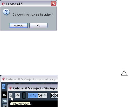
255
File handling
Open Other
The “Open Other” button allows you to open any project
file on your system. This is identical to using the Open
command from the File menu, see below.
Open
The “Open…” command on the File menu is used for
opening saved project files.
1. Select “Open…” from the File menu.
A file dialog opens, allowing you to select a project.
2. Click Open to open the selected project.
•Several projects can be open at the same time.
This is useful if you want to copy parts or entire sections from one project
to another.
3. If there is already an open project, you will be asked if
you want to activate the new project.
•Click No to open the project inactive.
This significantly reduces load times, especially for large projects.
•Click Activate to open and activate the new project.
The active project is indicated by the blue Activate Project button in the
upper left corner of the Project window. To activate a different project,
simply click its Activate Project button.
•You can also open project files by selecting an entry
from the “Recent Projects” submenu on the File menu.
This submenu lists the projects you have recently worked with, with the
most recent at the top of the list. This list can also be found in the Project
Assistant dialog, see “New Project” on page 254.
•You can also set Cubase AI to automatically open a
project when you launch the program (see “Startup Opti-
ons” on page 257).
About the “Missing Ports” dialog
If you open a Cubase AI project created on a different sys-
tem (other audio hardware), the program tries to find
matching audio inputs and outputs for the i/o busses (this is
one of the reasons why you should use descriptive, generic
names for your input and output ports – see “Preparations”
on page 10).
If the program cannot resolve all audio/MIDI inputs and
outputs used in the project, a Missing Ports dialog will
open. This allows you to manually re-route any ports spec-
ified in the project to ports available in your system.
Close
The Close command on the File menu closes the active
window. If a Project window is active, selecting this closes
the corresponding project.
•If the project contains unsaved changes, you are asked
whether you want to save it before closing.
If you select “Don’t Save” and have recorded or created new audio files
since saving, you will be asked if you want to delete or keep these.
Save and Save As
The commands Save and Save As allow you to save the
active project as a project file (file extension “.cpr”). The
Save command stores the project under its current name
and location, while Save As allows you to rename and/or
relocate the file. If a project has not been saved yet or if it
has not been changed since it was last saved, only Save
As is available.
A word about file extensions
Under Windows, file types are indicated by three letter file
name extensions (such as *.cpr for Cubase AI project files).
Under Mac OS X, it is not necessary to use file name ex-
tensions, since the file types are stored internally in the
files. However, if you want your Cubase AI projects to be
compatible with both platforms, you should make sure the
option “Use File Extension in File Dialog” is activated in
the Preferences (General page). When this is activated,
the proper file name extension is automatically added
when you save a file.
!
Generally, we recommend that you save project files
in their project folders, to keep the projects as
manageable as possible.
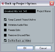
256
File handling
Save New Version
This function is only available as a key command, by de-
fault [Ctrl]/[Command]-[Alt]/[Option]-[S]. When you use
this function, an identical, new project file is being created
and activated.
The new file will get the same name as the original project,
but with an incremental number attached. For example, if
your project is called “My Project”, you will get new versions
called “My Project-01”, “My Project-02”, and so on.
Save New Version is useful if you are experimenting with
edits and arrangements and want to be able to go back to
a previous version at any time. The newest versions are al-
ways listed on the Recent Projects submenu on the File
menu for instant access (see also “Opening recent pro-
jects” on page 254).
Save as Template
This function allows you to save the current project as a
template. When you create a new project, the available
templates are listed, allowing you to base the new project
on a template.
Proceed as follows:
1. Set up a project.
2. Select “Save As Template…” from the File menu and
enter a name for the new project template.
•In the Tag Editor section you can assign the template to
one of the four template categories shown in the Project
Assistant dialog (see “New Project” on page 254) and/or
enter a description for the template.
Simply select a category value from the Template Type pop-up menu
and/or enter a description in the Content Summary field.
ÖIf you do not choose a Template Type attribute, the
new template will be shown in the More category in the
Project Assistant dialog.
3. Click OK to save the template.
•Templates can contain clips and events just like regular
projects.
If this is not what you want, make sure to remove all clips from the Pool
before you save the project as a template.
Templates are always stored in the Templates folder, see
“Where are the settings stored?” on page 267.
Setting up a default template
If you always want the same default project to open when
you launch Cubase AI, you can save a default template.
Proceed as follows:
1. Set up a project.
2. Select “Save As Template…” from the File menu and
save the project template with the name “default”.
3. Open the Preferences dialog and select the General
page.
4. Open the “On Startup” pop-up and select “Open ‘De-
fault’ Template”.
The next time you launch Cubase AI, the default template
will automatically be opened. For details on the other Star-
tup options, see “Startup Options” on page 257.
ÖIn the Project Assistant dialog, the default project tem-
plate is found in the More category.
Back up Project
This function is very useful if you want to move or backup
your project.
1. Select “Back up Project…” from the File menu.
A file dialog opens in which you can choose an existing empty folder or
create a new folder to save the project.
2. Click OK.
The “Back up Project Options” dialog opens.
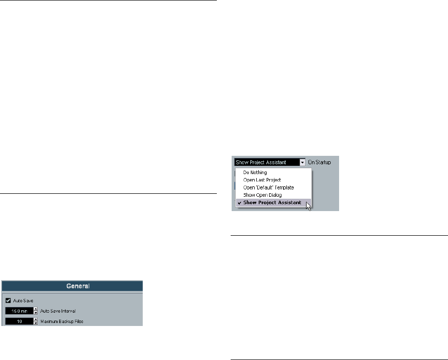
257
File handling
This dialog contains the following options:
3. Make the desired settings.
4. Click OK.
A copy of the project is saved in the new folder. The original project is
not affected.
Auto Save
If you activate the Auto Save option in the Preferences
(General page), Cubase AI will automatically save backup
copies of all open projects with unsaved changes.
These backup copies are named “<project name>-
xx.bak”, where xx is an incremental number. Unsaved
projects are backed up in a similar way as “UntitledX-
xx.bak”, with X being the incremental number for unsaved
projects. All backup files are saved in the project folder.
•Use the “Auto Save Interval” setting to specify the time
intervals in which a backup copy will be created.
•Use the “Maximum Backup Files” option to specify how
many backup files will be created with the Auto Save
function.
When the maximum number of backup files is reached, the existing files
will be overwritten (starting with the oldest file).
ÖWith this option only the project files themselves will
be backed up. If you want to include the files from the Pool
and save your project in a different location, you need to
use the “Back up Project” function.
Startup Options
The “On Startup” pop-up menu in the Preferences (Gen-
eral page) allows you to specify what should happen each
time you launch Cubase AI.
The following options are available:
Revert
If you select “Revert” from the File menu, you will be asked
whether you really want to revert to the last saved version
of the project. If you click “Revert”, all changes you have
made since saving will be discarded.
If you have recorded or created new audio files since sav-
ing, you will be asked whether you want to delete or keep
these.
Option Description
Project Name Enter a project name if you want to change it from the de-
fault (the current name of the project).
Keep Current
Project Active When this option is activated, the current project will still
be the active project after clicking OK. If you wish to
switch to the new backup project instead, you need to
deactivate this option.
Minimize Audio
Files If this is activated, only the audio file portions that are ac-
tually used in the project will be included. This can signi-
ficantly reduce the size of the project folder (if you are
using small sections of large files), but it also means you
cannot use other portions of the audio files if you con-
tinue working with the project in its new folder.
Freeze Edits This will perform a Freeze Edits operation, making all pro-
cessing and applied effects permanent to each clip in the
Pool, see “Freeze Edits” on page 123.
Remove
Unused Files When this is activated, only files in the Pool that are actu-
ally used in the project will be stored in the new folder.
Do Not Back
up Video When this is activated, any video clips on the video track
or in the Pool of the current project will not be included in
the backup project.
Option Description
Do Nothing Cubase AI launches without opening a project.
Open Last
Project The last saved project is opened on launch.
Open ‘Default’
Template The default template is opened, see “Setting up a de-
fault template” on page 256.
Show Open
Dialog The Open dialog opens on launch, allowing you to man-
ually locate and open the desired project.
Show Project
Assistant The Project Assistant dialog opens on launch, allowing
you to open a recently opened project or to create a
new project from one of the templates (see “New Pro-
ject” on page 254).

258
File handling
Importing audio
In Cubase AI audio can be imported in a variety of differ-
ent formats. For example, you can import audio files saved
in different formats (compressed and uncompressed).
For information on audio file import preferences, see “Audio
file import options” on page 27. For information on how to
import audio files into the Pool and import options, see
“About the Import Medium dialog” on page 151.
Importing ReCycle files
ReCycle by Propellerhead Software is a program designed
especially for working with sampled loops. By “slicing” a
loop and making separate samples of each beat, ReCycle
makes it possible to match the tempo of a loop and edit the
loop as if it was built of individual sounds. Cubase AI can
import two file types created by ReCycle:
• REX files (export file format of the first versions of ReCycle,
extension “.rex”).
• REX 2 files (file format of ReCycle 2.0 and later, extension
“.rx2”).
Proceed as follows:
1. Select an audio track and move the project cursor to
where you want the imported file to start.
You probably want to import REX files to tempo based audio tracks, since
this will allow you to change the tempo later on (having the imported REX
file automatically adjust).
2. Select “Audio File…” from the Import submenu on the
File menu.
3. On the file type pop-up menu in the file dialog, select
REX File or REX 2 File.
4. Locate and select the file you want to import, and click
Open.
The file is imported and automatically adjusted to the current Cubase AI
tempo.
Unlike a regular audio file, the imported REX file will con-
sist of several events, one for each “slice” in the loop. The
events will automatically be placed in an audio part on the
selected track and positioned so that the original internal
timing of the loop is preserved.
5. If you now open the part in the Audio Part Editor, you
can edit each slice separately by muting, moving and re-
sizing events, adding effects and processing, etc.
You can also adjust the tempo and have the REX file automatically follow
(provided that its track is tempo based).
ÖYou can achieve similar results by using Cubase AI’s
own loop slicing features, see “Working with hitpoints and
slices” on page 134.
Importing compressed audio files
Cubase AI can import (and export, see “Mixing down to
audio files” on page 227) several common audio com-
pression formats. The procedure is the same as when im-
porting any non-compressed audio file, with one important
thing to note:
•When you import a compressed audio file, Cubase AI
creates a copy of the file and converts this to Wave format
(Windows) or AIFF format (Mac OS X) before importing it.
The original compressed file will not be used in the project.
The imported file is placed in the designated project Audio folder.
The following file types are supported:
MPEG audio files
MPEG, which stands for Moving Picture Experts Group, is
the name of a family of standards used for encoding audio-
visual information (e.g. movies, video, music) in a digital
compressed format.
Cubase AI can read MPEG Layer 3 (*.mp3) files.
Windows Media Audio files (Windows only)
Windows Media Audio is an audio format developed by
Microsoft, Inc. Due to advanced audio compression algo-
rithms, Windows Media Audio files can be made very
small, maintaining good audio quality. The files have the
extension “.wma”.
ÖFor exporting Audio, see the chapter “Export Audio
Mixdown” on page 226.
!
For this to work, the REX Shared Library needs to be
installed on your system. If this is not the case, you will
find the corresponding installer on the installation DVD
(in the “Additional Content\Installer Data” folder).
!
The resulting Wave/AIFF file will be several times
larger than the original compressed file.
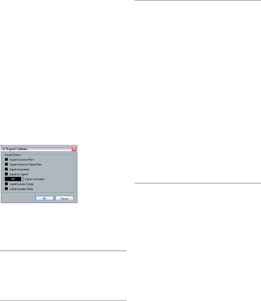
259
File handling
Exporting and importing standard
MIDI files
Cubase AI can import and export Standard MIDI Files,
which makes it possible to transfer MIDI material to and
from virtually any MIDI application on any platform. When
you import and export MIDI files, you can also specify
whether certain settings associated with the tracks should
be included in the files (automation tracks, volume and
pan settings, etc.).
Exporting MIDI files
To export your MIDI tracks as a standard MIDI file, pull
down the File menu and select “MIDI File…” from the Ex-
port submenu. A regular file dialog opens, allowing you to
specify a location and name for the file.
When you have specified a location and a name for the file,
click “Save”. The Export Options dialog opens, allowing you
to specify a number of options for the file – what should be
included in the file, its type and its resolution (see below for
a description of the options).
The Export Options dialog
You will also find these settings in the Preferences (MIDI–
MIDI File page). If you set these up in the Preferences, you
only need to click OK in the Export Options dialog to
proceed.
The dialog contains the following options:
ÖThe MIDI file will include the tempo information of the
project (i.e. it will include the tempo and time signature
events of the Tempo Track Editor or, if the Tempo Track is
deactivated on the Transport panel, the current tempo and
time signature).
ÖInspector settings other than those specified in the Ex-
port options are not included in the MIDI file!
Option Description
Export Inspec-
tor Patch If this is activated, the MIDI patch settings in the Inspec-
tor – Bank Select and Program Select (used for selecting
sounds in the connected MIDI instrument) are included
as MIDI Bank Select and Program Change events in the
MIDI file.
Export Inspec-
tor Volume/
Pan
If this is activated, Volume and Pan settings made in the
Inspector are included as MIDI Volume and Pan events in
the MIDI file.
Export
Automation If this is activated, the automation data (as heard during
playback) are converted to MIDI controller events and in-
cluded in the MIDI file, see the chapter “Automation” on
page 108.
Note that if a continuous controller (e.g. CC7) has been
recorded but the Read button is deactivated for the auto-
mation track (i.e. the automation is effectively switched
off for this parameter), only the part data for this controller
will be exported.
If this option is deactivated and the Automation Read
button is activated, no Continuous Controllers are ex-
ported. If the Read button is deactivated, the Controller
data of the MIDI part are exported (these will now be han-
dled like “regular” part data).
In most cases, you would probably activate this option.
Export as
Type 0 If this is activated, the MIDI file will be of type 0 (all data
on a single track, but on different MIDI channels). If you
do not activate this option, the MIDI file will be of Type 1
(data on separate tracks). Which type to choose de-
pends on what you want to do with the MIDI file (in which
application or sequencer it should be used, etc.).
Export
Resolution You can specify a MIDI resolution between 24 and 960
for the MIDI file. The resolution is the number of pulses, or
ticks, per quarter note (PPQ) and determines the preci-
sion with which you will be able to view and edit the MIDI
data. The higher the resolution, the higher the precision.
The resolution should be chosen depending on the appli-
cation or sequencer with which the MIDI file will be used
though, since certain applications and sequencers may
not be able to handle certain resolutions.
Export Locator
Range If this is activated, only the range between the locators
will be exported.
Export
includes Delay If this is activated, the delay of the MIDI track will be in-
cluded in the MIDI file. For more information about the
Delay option, see “Basic track settings” on page 167.
Option Description

260
File handling
Importing MIDI files
To import a MIDI file from disk, proceed as follows:
1. Select “MIDI File…” from the Import submenu on the
File menu.
2. If there is already an open project, a dialog opens in
which you can select whether a new project should be
created for the file.
If you select “No”, the MIDI file will be imported into the current project.
3. Locate and select the MIDI file in the file dialog that
opens and click Open.
•If you choose to create a new project, select the project
folder.
Select an existing project folder or create a new one.
The MIDI file is imported. The result depends on the con-
tents of the MIDI file and the Import Options settings in the
Preferences dialog (MIDI–MIDI File page). The Import Op-
tions are as follows:
Option Description
Extract First
Patch If this is activated, the first Program Change and Bank
Select events for each track are converted to Inspector
settings for the track.
Extract First
Volume/Pan If this is activated, the first MIDI Volume and Pan events
for each track are converted to Inspector settings for the
track.
Import Con-
troller as Auto-
mation Tracks
If this is activated, MIDI controller events in the MIDI file
will be converted to automation data for the MIDI tracks.
If this is deactivated, controller data for the MIDI Parts will
be imported.
Import to Left
Locator If this is activated, the imported MIDI file will be placed so
that it starts at the position of the left locator – otherwise
it will start at the beginning of the project. Note that if you
choose to have a new project created automatically, the
MIDI file will always start at the beginning of the project.
Import
dropped File
as single Part
If this is activated and you drag and drop a MIDI file into
the project, the whole file will be placed on a single track.
Ignore Master
Track Events
on Merge
If this is activated and you import a MIDI file into the cur-
rent project, tempo track data in the MIDI file are ignored.
The imported MIDI file will play according to the current
tempo track in the project.
If this option is deactivated, the Tempo Track Editor will be
adjusted according to the tempo information in the MIDI
file.
Auto Dissolve
Format 0 If this is activated and you import a MIDI file of type 0 into
the project, the file will automatically be “dissolved”: For
each embedded MIDI channel in the file, a separate track
will be inserted in the Project window.
If this is deactivated, only one MIDI track will be created.
This track will be set to MIDI Channel “Any”, allowing all
MIDI events to play back on their original channels. You
can also use the “Dissolve Part” function on the MIDI
menu to distribute the events onto different tracks with
different MIDI Channels at a later stage.
Import to In-
strument
tracks
If this is activated and you drag a MIDI file into the
project, an Instrument track will be created instead of a
MIDI track. Furthermore, the program will load the corre-
sponding track preset for the instrument track (based on
the program change events included in the MIDI file).
Option Description
25
Customizing
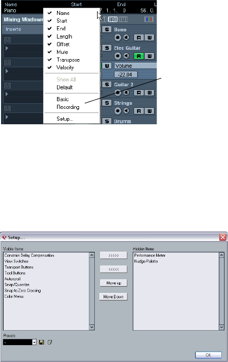
262
Customizing
Background
The user can customize the appearance and functionality
of Cubase AI in various ways.
User configurable items described in this chapter are:
•Setup dialogs
Several parts of the user interface (toolbars, Transport panel, Inspector,
info lines and Channel Settings windows) provide a Setup dialog, where
you can configure which items of the respective window area or panel are
to be shown or hidden and where they should be located – see “Using the
Setup options” on page 262.
•Track list
The controls shown in the Track list can be set for each track type – see
“Customizing track controls” on page 263.
•Appearance
The general look of the program can be adjusted – see “Appearance” on
page 265.
•Track and event colors
You can adjust which colors should be used – see “Applying track and
event colors” on page 265.
This chapter also contains a section describing where your
preferences and settings are stored (see “Where are the
settings stored?” on page 267), to help you transfer your
customized settings to another computer.
Using the Setup options
You can customize the appearance of the following ele-
ments:
• Transport panel
• Info line
• Channel Settings window
• Toolbars
• Inspector
The setup context menus
If you right-click the Transport panel, the toolbars, the info
lines, or the Inspector, the respective setup context menu
opens. For Channel Settings windows, these options are
found in the dialog’s context menu, on the Customize
View submenu. Here, you can activate/deactivate ele-
ments as desired.
The following general options are available on the setup
context menus:
•“Show All” makes all items visible.
•“Default” resets the interface to the default setting.
•“Setup…” opens the Setup dialog (see below).
If presets are available, they can be selected on the lower
half of the menu.
The info line setup context menu
The Setup dialogs
If you select “Setup…” from the setup context menus, the
Setup dialog opens. This allows you to specify which ele-
ments should be visible/hidden and to set the order of the
elements. You can also save and recall setup presets in
this dialog.
The dialog is divided into two sections. The left section
displays the currently visible items and the right section
displays the currently hidden items.
This section shows
Setup presets, if
available.
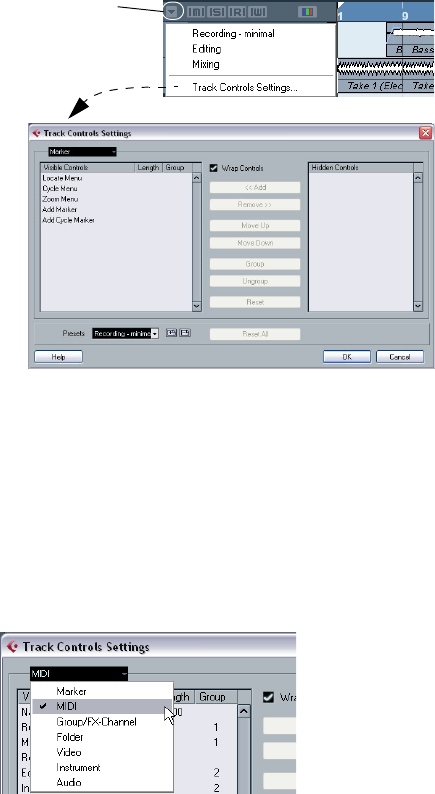
263
Customizing
•You can change the current show/hide status by select-
ing items in one section and then use the arrow buttons in
the middle of the dialog to move them to the other section.
Changes are applied directly.
•By selecting items in the “Visible Items” list and using the
Move Up and Move Down buttons, you can reorder the
items list.
Changes are applied directly. To undo all changes and revert to the stan-
dard layout, select “Default” on the setup context menu.
•If you click the Save button (disk icon) in the Presets
section, a dialog opens, allowing you to name the current
configuration and save it as a preset.
•To remove a preset, select it on the presets pop-up
menu and click the trash icon.
•Saved configurations are available for selection from the
Presets pop-up in the Setup dialog or directly from the
setup context menu.
Customizing track controls
For each track type you can configure which track controls
should be shown in the Track list. You can also specify the
order of controls and group controls so that they are always
shown adjacent to each other. This is done using the Track
Controls Settings dialog.
Opening the Track Controls Settings dialog
There are two ways to open the dialog:
•Right-click a track in the Track list and select “Track
Controls Settings…” from the context menu.
•Click the arrow in the top left corner of the Track list and
select “Track Controls Settings…”.
Setting the track type
The settings made in the Track Controls Settings dialog
apply to the selected track type, which is shown in the
menu display in the top left corner of the dialog.
•To change the track type, click the arrow to the right in
the menu display and select a track type from the pop-up
menu that opens.
All settings made in the dialog will apply to all tracks (current and subse-
quent) of the selected type.
The Track Type pop-up in the Track Controls Settings dialog
ÖAlways make sure that you have selected the desired
track type when editing the track controls!
Click here to open
the pop-up menu.
264
Customizing
Removing, adding and moving track controls
The dialog is divided into two sections. The left section
displays controls currently visible on the Track list, and the
right section displays the controls currently hidden.
•You can hide controls from the Track list by selecting
them in the list to the left and clicking the Remove button.
To show hidden elements, select them in the list to the
right and click the Add button.
Click OK to apply the changes.
ÖAll controls can be removed except the Mute and Solo
buttons.
•By selecting controls in the “Visible Controls” list and
using the Move Up and Move Down buttons, you can
change the order of the list.
Click OK to apply the changes.
Grouping track controls
If you resize the Track list, the position of the controls will
change dynamically to accommodate as many controls as
possible in the available space (given that Wrap Controls is
activated – see below). By grouping several track controls
you ensure that they are always be positioned side by side
in the Track list. To group controls, proceed as follows:
1. Make sure you have selected the correct track type.
2. In the “Visible Controls” section, select at least two
controls.
You can only group controls that are adjacent to each other in the list. To
group controls that are currently not adjacent in the list, use the Move Up/
Down buttons first.
3. Click Group.
A number is displayed in the Group column for the grouped controls. The
first group created has the number 1, the second 2, and so on.
4. Click OK.
The controls are now grouped.
•You can ungroup commands by using the Ungroup but-
ton. Please note that this will remove the selected element
and the elements below it in the list from this group. To re-
move an entire group, select the first (topmost) element
belonging to this group and click the Ungroup button.
About Wrap Controls
This is activated by default. Wrap Controls allows the con-
trols to be dynamically repositioned when resizing the Track
list. That is, as many controls as possible will be displayed
depending on the current size of the Track list.
If you deactivate Wrap Controls, the positions of the con-
trols are fixed, regardless of the size of the Track list. In this
mode, you may have to resize the tracks vertically (by drag-
ging the dividers between them) to display all the controls.
About the Length column
The Length column in the Visible Controls list allows you to
set the maximum length for certain text fields, e.g. Name.
To change the setting, click on the number in the Length
column and type in a new value.
Resetting Track list settings
You have two possibilities to reset the settings:
•Click Reset to restore all default track controls settings
for the selected track type.
•Click Reset All to restore all default track controls set-
tings for all track types.
Saving presets
You can save track controls settings as presets for later
recall:
1. Click on the Save button (the plus sign) to the right of
the Presets pop-up menu.
A dialog opens, asking you to type in a name for the preset.
2. Click OK to save the settings as a preset.
Saved presets are available for selection from the Presets pop-up menu
and from the pop-up menu in the top left corner of the Track list.
•To remove a preset, select it in the Track Controls Set-
tings dialog and click the Delete button (the minus sign).
ÖCubase AI comes with a number of Track Control Set-
tings presets available.
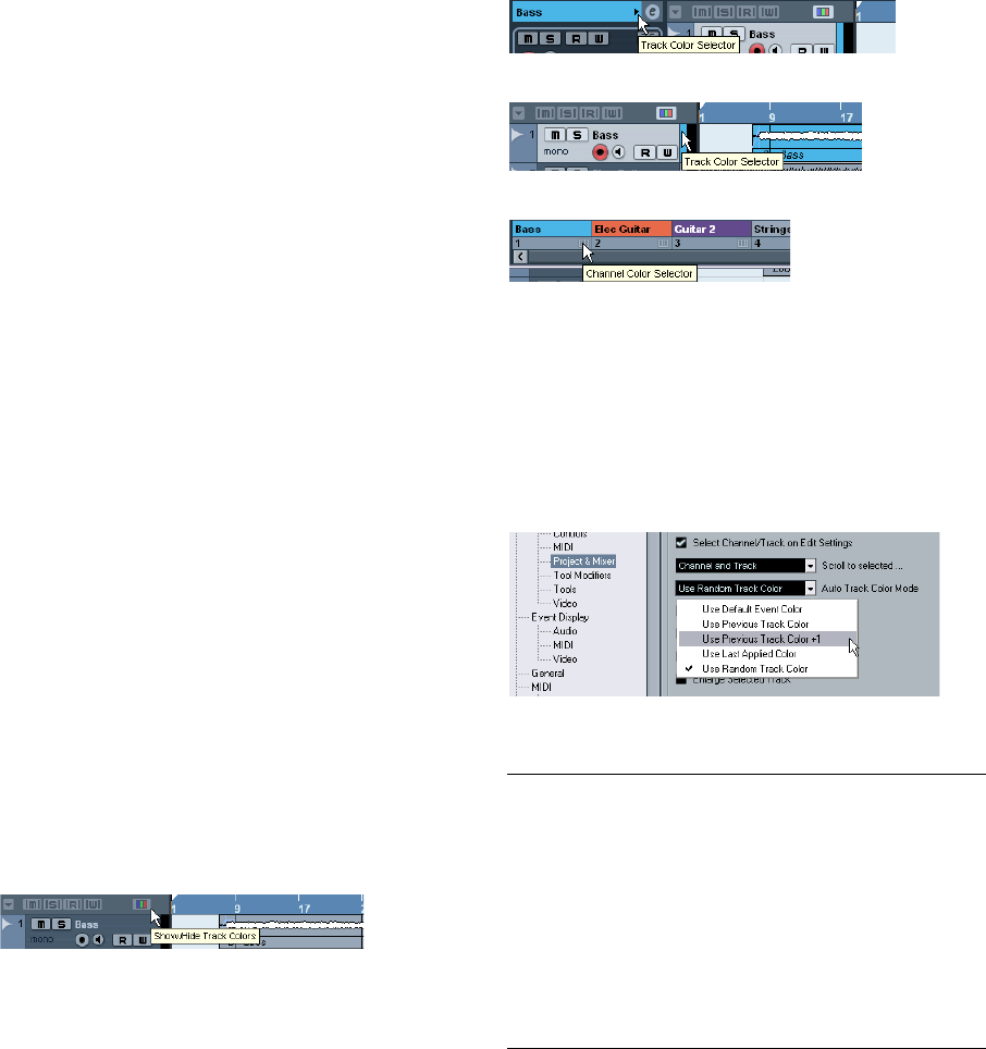
265
Customizing
Appearance
In the Preferences dialog, you will find a page called Ap-
pearance. The following settings are available:
•Basic Appearance Scheme
By selecting an option from this pop-up menu you can adjust the general
look of the program. After selecting an Appearance Scheme and clicking
Apply or OK, you need to restart the program for the changes to take
effect.
•Brightness/Intensity sliders
These sliders allow you to fine-tune the brightness and contrast in various
areas in the program. Changes take effect when you click Apply or OK.
Applying track and event colors
You can use color scheming for easier overview of tracks
and events in the Project window. Applying colors is di-
vided into two areas; track and event colors.
•A track color is shown and can be edited in the Inspector,
the Track list, and the corresponding channel in the Mixer. It
is furthermore displayed in all parts and events for the track
in the event display.
Track colors can be switched on and off globally.
•Event colors are shown for parts and events in the event
display and are independent from the track colors.
ÖAn applied event color “overrides” the track color, if
both are used.
The color palette can be customized, see “The Event Co-
lors dialog” on page 266.
Track colors
Applying track colors manually
To activate track colors, proceed as follows:
1. Click the Show/Hide Track Colors button at the top of
the Track list.
This brings up the Track Color Selector in the Inspector,
the Track list and in the Mixer.
2. To bring up the color palette, click the Track Color
Selector.
Click the arrow in the track name title bar or…
…click the color strip in the Track list.
In the Mixer, click the Channel Color Selector below the channel name.
3. Select a color from the color bar.
The track color is now applied to the Inspector title palette and the Track
list as well as the channel strips in the Mixer and any parts and events on
the selected track.
Applying track colors automatically
In the Preferences (Editing–Project & Mixer page), you
can find the option “Auto Track Color Mode”.
This offers you several options for automatically assigning
colors to tracks that are added to the project.
Option Effect
Use Default
Event Color The default color (gray) is assigned.
Use Previous
Track Color Uses the color of the track above the new one (i.e. the
track that is selected when you add a new track).
Use Previous
Track Color
+1
Uses the color next to the color of the track above the
new one (+1 refers to the color number in the palette).
Use Last
Applied Color The last manually assigned color is used.
Use Random
Track Color Track colors are assigned randomly.
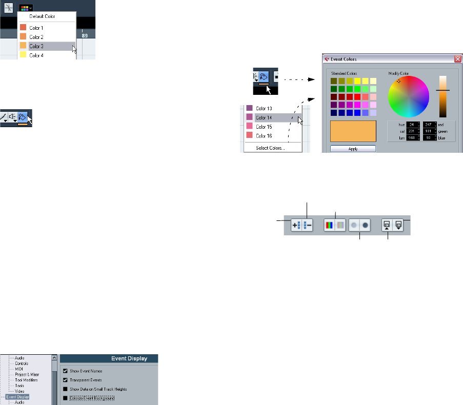
266
Customizing
Coloring parts and events
There are two ways to color parts and events in the
Project window:
Using the color selector
1. Select the desired parts or events.
2. Choose a color from the Color Selector in the toolbar.
Using the Color tool
1. On the toolbar, select the Color tool.
2. Click the small strip below it to bring up the color pal-
ette.
3. Select a color.
4. Click on a part/event to assign the color.
The color is applied to all selected parts/events and over-
rides the track color (if used).
•If you press [Ctrl]/[Command] and click on a part/event
with the Color tool, the color palette is displayed and you
can choose the desired color for an event.
•If you press [Alt]/[Option], the Color tool cursor becomes
a pipette, which can be used to select a color by clicking on
a part/event.
Customizing the event background
On the Event Display page in the Preferences dialog, you
can find the option “Colorize Event Background”.
This option affects the display of events in the Project
window.
•When this is activated, the events and parts in the event
display will have the selected background color.
•When this is deactivated, the event “content”, e.g. MIDI
events and audio waveforms, are displayed in the selected
color and the event background is gray.
The Event Colors dialog
You can open the Event Colors dialog in two ways:
•Double-click the small strip below the Color tool.
•Open the Color pop-up menu on the toolbar and select
“Select Colors…”.
In the Event Colors dialog, you can fully customize the
color palette, apart from the default color (gray).
To add new colors to the color palette, proceed as follows:
1. Click the Insert New Color button in the Event Colors
section to add a new color.
A new color icon and color name are added to the Event Colors section.
2. Click the color field next to the name field to activate
the new color for editing.
3. In the Standard Colors section, select the standard
color. You can modify the selected color as follows:
• Drag the cursor to another point in the color circle.
• Move the handle in the color meter.
• Enter the values for red, green and blue and hue, saturation
and luminosity manually.
Remove Selected Color Increase/decrease intensity
for all colors
This Set As
Default Set
Increase/decrease brightness
for all colors
Insert New
Color
Use Default Set
267
Customizing
4. Click the Apply button in the Standard Colors section.
The color setting is applied to the selected color field in the Event Colors
section.
You can edit every existing event color in the same way.
•To delete an event color item, select it and click the “Re-
move Selected Color” button in the Event Colors section.
•To increase or decrease the intensity and the brightness
of all colors, use the corresponding buttons in the Event
Colors section.
•To save the current set as default, click the button “This
Set As Default Set” in the Event Colors section. You can
then click the button “Use Default Set” to the right to ap-
ply the default set.
•To return to the standard setting of the palette in Cu-
base AI, click Reset.
Where are the settings stored?
As you have seen, there are a large number of ways in
which you can customize Cubase AI. While some of the
settings you make are stored with each project, others are
stored in separate preference files.
If you need to transfer your projects to another computer
(e.g. in another studio), you can bring all your settings along
by copying the desired preference files and installing them
on the other computer.
ÖIt is a good idea to make a backup copy of your prefer-
ence files once you have set things up the way you want!
This way, if another Cubase AI user wants to use his or her personal set-
tings when working on your computer, you can restore your own prefer-
ences afterwards.
•Under Windows XP, preference files are stored in the
folder “\Documents and Settings\<user name>\Applica-
tion Data\Steinberg\Cubase AI 5\”.
On the Start menu, you will find a shortcut to this folder for easy access.
•Under Windows Vista, preference files are stored in the
folder “\Users\<user name\AppData\Roaming\Stein-
berg\Cubase AI 5\”.
On the Start menu, you will find a shortcut to this folder for easy access.
•Under Mac OS X, preference files are stored in the
folder “/Library/Preferences/Cubase AI 5/” under your
home directory.
The full path would be: “/Users/<user name>/Library/Preferences/
Cubase AI 5/”.
ÖThe RAMpresets.xml file, which contains various pre-
sets settings (see below), is saved when exiting the pro-
gram.
ÖProgram functions (e.g. crossfade) or configurations
(e.g. panels) not used in the project will not be stored.
Some of the preferences are not stored in the default pref-
erences folder. A list can be found in the article “Files for
the program settings and preferences” in the Steinberg
Knowledge Base.
To open the Knowledge Base, browse to the Steinberg
web site, click “Support” and choose “Knowledge Base”
in the list on the left.
26
Key commands
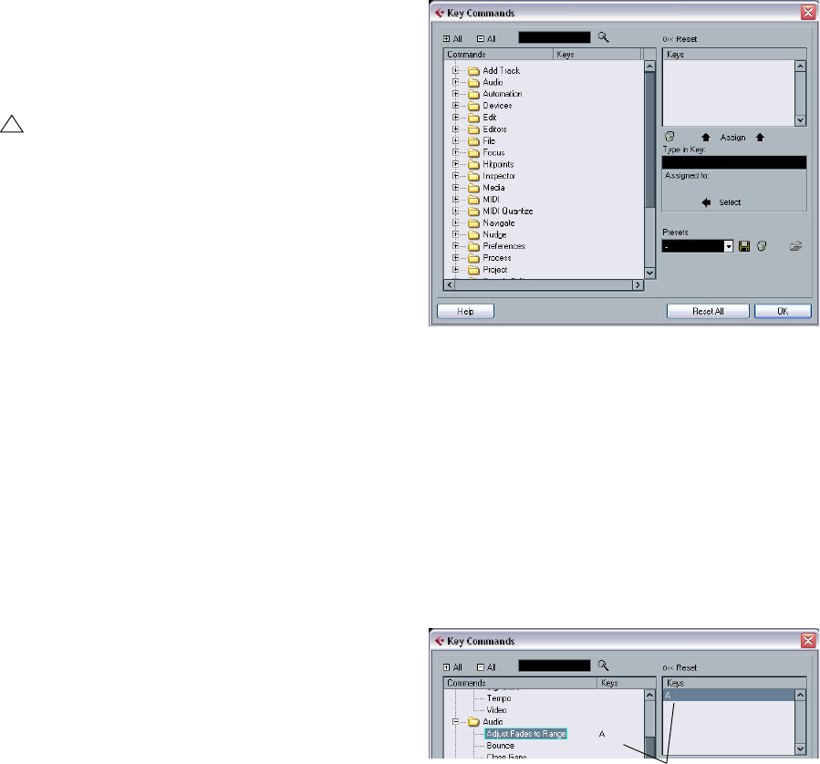
269
Key commands
Introduction
Most of the main menus in Cubase AI have key command
shortcuts for certain items on the menus. In addition, there
are numerous other Cubase AI functions that can be per-
formed via key commands. These are all default settings. If
you want, you can customize existing key commands to
your liking, and also add commands for menu items and
functions that have no key command assigned.
How are key commands settings saved?
Every time you edit or add any key command assignment,
this is stored as a global Cubase AI preference – not as
part of a project. Hence, if you edit or add a key command
assignment, any subsequent projects that you create or
open will use these modified settings. However, the de-
fault settings can be restored at any time by clicking the
Reset All button in the Key Commands dialog.
In addition, you can save key commands settings as a “key
commands file”, which is stored separately and can be im-
ported into any project. This way you can quickly and easily
recall customized settings, when moving projects between
different computers, for example. The settings are saved in
an .xml file on the hard disk.
How to save key commands settings is described in the
section “About key commands presets” on page 270.
Setting up key commands
The following is a description of how you set up key com-
mands and save them as presets for easy access. Key
commands settings are accessed and edited in the Key
Commands dialog.
Adding or modifying a key command
In the Key Commands dialog you will find all main menu
items and a large number of other functions, arranged in a
hierarchical way similar to the Windows Explorer and Mac
OS Finder. The function categories are represented by a
number of folders, each containing various menu items and
functions. When you open a category folder by clicking the
plus sign beside it, the items and functions it contains are
displayed with the currently assigned key commands.
To add a key command, proceed as follows:
1. Pull down the File menu and select “Key Commands…”.
The Key Commands dialog appears.
2. In the Commands list on the left, choose a category.
3. Click the plus sign to open the category folder and
display the items it contains.
Note that you can also click the “global” plus and minus signs in the top
left corner to open and close all category folders at once.
4. In the list, select the item to which you want to assign
a key command.
Already assigned key commands are shown in the Keys column as well
as in the Keys section in the top right corner.
5. Alternatively, you can use the search function in the
dialog to find the desired item.
For a description of how to use the search function, see below.
!
You can also assign tool modifier keys, i.e. keys that
change the behavior of various tools when pressed.
This is done in the Preferences dialog – see “Setting
up tool modifier keys” on page 271.
Key commands are displayed here.
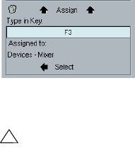
270
Key commands
6. When you have found and selected the desired item,
click in the “Type in Key” field and enter a new key com-
mand.
You can choose any single key or a combination of one or several modifier
keys ([Alt]/[Option], [Ctrl]/[Command], [Shift]) plus any key. Just press the
keys you want to use.
7. If the key command you entered is already assigned to
another item or function, this is displayed below the “Type
in Key” field.
You can either ignore this and proceed to assign the key command to
the new function instead, or you can select another key command.
8. Click the Assign button above the field.
The new key command appears in the Keys List.
9. Click OK to exit the dialog.
ÖYou can set up several different key commands for the
same function. Adding a key command to a function that
already has another key command will not replace the key
command previously defined for the function. If you wish
to remove a key command, see below.
Searching for key commands
If you want to know which key command is assigned to a
certain function in the program, you can use the Search
function in the Key Commands dialog:
1. Click in the search text field at the top left of the dialog
and type in the function for which you want to know the key
command.
This is a standard word search function, so you should type the command
as it is spelled in the program. Partial words can be used; to search for all
quantize related commands, type “Quantize”, “Quant”, etc.
2. Click the Search button (the magnifying glass icon).
The search is conducted and the first matching command is selected
and displayed in the Commands list below. The Keys column and the
Keys list show the assigned key commands, if any.
3. To search for more commands containing the word(s)
you entered, click the Search button again.
4. When you are done, click OK to close the dialog.
Removing a key command
To remove a key command, proceed as follows:
1. Use the list of categories and commands to select the
item or function for which you wish to remove a key com-
mand.
The key command is shown in the Keys column and the Keys list.
2. Select the key command in the Keys list and click the
Delete button (the trash icon).
You are asked whether you really want to remove the key command.
3. Click Remove to remove the selected key command.
4. Click OK to close the dialog.
About key commands presets
As mentioned above, any changes made to the key com-
mands are automatically stored as a Cubase AI preference.
However, it is also possible to store key commands settings
separately. This way, you can store any number of different
key command settings as presets for instant recall.
Saving key commands presets
Proceed as follows:
1. Set up the key commands to your liking.
When setting up key commands, remember to click “Assign” to make the
changes.
2. Click the Save button next to the Presets pop-up
menu.
A dialog appears, allowing you to type in a name for the preset.
3. Click OK to save the preset.
Your saved key commands settings are now available on the Presets
pop-up menu.
!
If the key command you enter is already assigned to
another function, you will get a warning message ask-
ing if you really want to reassign the command to the
new function.
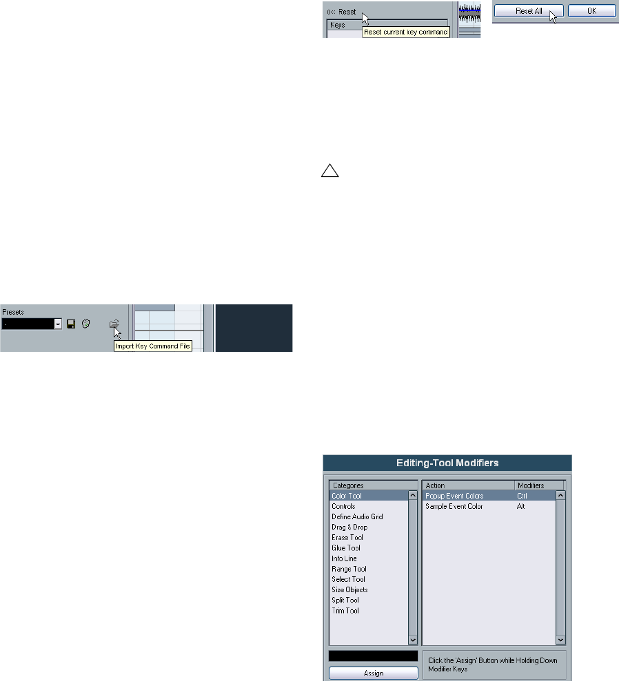
271
Key commands
Loading key command presets
To load a key command preset, simply select it from the
Presets pop-up menu.
ÖNote that this operation may replace existing key com-
mands!
The key command settings you load will replace the current key command
settings for the same functions (if any). If you want to be able to revert to
your current settings again, make sure to save them first, as described
above!
Loading earlier key commands settings
If you have saved key commands settings with an earlier
program version, it is possible to use them in Cubase AI 5,
by using the “Import Key Command File” function, which
lets you load and apply saved key commands:
1. Open the Key Commands dialog.
2. Click the “Import Key Command File” button to the
right of the Presets pop-up menu.
A standard file dialog opens.
3. In the file dialog, use the “Files of type” pop-up menu
to specify if you want to import a key commands file
(“.key”).
When you have imported an older file, you might want to save it as a pre-
set (see above) to be able to access it from the Presets pop-up menu in
the future.
4. Navigate to the file you want to import and click “Open”.
The file is imported.
5. Click OK to exit the Key Commands dialog and apply
the imported settings.
The settings in the loaded key commands file now replace the current
settings.
About the “Reset” and “Reset All” functions
These two buttons in the Key Commands dialog will both
restore the default settings. The following rules apply:
•“Reset” will restore the default key command setting for
the function selected in the Commands list.
•“Reset All” will restore the default key commands for all
commands.
Setting up tool modifier keys
A tool modifier key is a key you can press to get an alter-
nate function when using a tool. For example, clicking and
dragging an event with the Arrow tool normally moves it –
holding down a modifier key (by default [Alt]/[Option]) will
copy it instead.
The default assignments for tool modifier keys can be
found in the Preferences (Editing–Tool Modifiers page).
Here, you can also edit them:
1. Open the Preferences dialog and select the Editing–
Tool Modifiers page.
!
Note that the “Reset All” operation will cause any
changes made to the default key commands to be
lost! If you want to be able to revert to these settings
again, make sure to save them first!

272
Key commands
2. Select an option in the Categories list, and locate the
action for which you want to edit the modifier key.
For example, the “Copy” action mentioned above resides in the category
“Drag & Drop”.
3. Select the action in the Action list.
4. Hold down the desired modifier key(s) and click the
Assign button.
The current modifier keys for the action are replaced. If the modifier keys
you pressed are already assigned to another tool, you will be asked
whether you want to overwrite them. If you do, this will leave the other
tool without any modifier keys assigned.
5. When you’re done, click OK to apply the changes and
close the dialog.
The default key commands
Below, the default key commands are listed according to
category.
•As described in the section “Key command conventi-
ons” on page 8, modifier keys are written as:
[Win modifier key]/[Mac modifier key].
For example, “[Ctrl]/[Command]-[N]” in the list below means “press [Ctrl]
under Windows or [Command] under Mac OS X, then press [N]”.
Audio category
Automation category
Devices category
Edit category
!
When the Virtual Keyboard is displayed, the usual key
commands are blocked because they are reserved for
the Virtual Keyboard. The only exceptions are: [Ctrl]/
[Command]-[S] (Save), Num [*] (Start/Stop Record),
[Space] (Start/Stop Playback), Num [1] (Jump to left
locator), [Delete] or [Backspace] (Delete), Num [/]
(Cycle on/off), [F2] (Show/Hide Transport panel), and
[Alt]/[Option]-[K] (Show/Hide Virtual Keyboard).
Option Key command
Adjust Fades to Range [A]
Crossfade [X]
Find Selected in Pool [Ctrl]/[Command]-[F]
Option Key command
Toggle Read Enable All Tracks [Alt]/[Option]-[R]
Toggle Write Enable All Tracks [Alt]/[Option]-[W]
Option Key command
Mixer [F3]
Virtual Keyboard [Alt]/[Option]-[K]
Video [F8]
VST Connections [F4]
VST Instruments [F11]
VST Performance [F12]
Option Key command
Autoscroll [F]
Copy [Ctrl]/[Command]-[C]
Cut [Ctrl]/[Command]-[X]
Cut Time [Ctrl]/[Command]-[Shift]-[X]
Delete [Delete] or [Backspace]
Delete Time [Shift]-[Backspace]
Duplicate [Ctrl]/[Command]-[D]
Insert Silence [Ctrl]/[Command]-[Shift]-[E]
Left Selection Side to Cursor [E]
Move to Cursor [Ctrl]/[Command]-[L]
Mute [M]
Mute Events [Shift]-[M]
Mute/Unmute Objects [Alt]/[Option]-[M]
Open Default Editor [Ctrl]/[Command]-[E]
Open Score Editor [Ctrl]/[Command]-[R]
Open/Close Editor [Return]
Paste [Ctrl]/[Command]-[V]
Paste at Origin [Alt]/[Option]-[V]
Paste Time [Ctrl]/[Command]-[Shift]-[V]
Record Enable [R]
Redo [Ctrl]/[Command]-[Shift]-[Z]
Repeat [Ctrl]/[Command]-[K]
Right Selection Side to Cursor [D]
Select All [Ctrl]/[Command]-[A]
Select None [Ctrl]/[Command]-[Shift]-[A]
Snap On/Off [J]
Solo [S]
Split At Cursor [Alt]/[Option]-[X]
Split Range [Shift]-[X]

273
Key commands
Editors category
File category
MIDI category
Navigate category
Nudge category
Project category
Undo [Ctrl]/[Command]-[Z]
Unmute Events [Shift]-[U]
Option Key command
Show/Hide Info view [Ctrl]/[Command]-[I]
Show/Hide Inspector [Alt]/[Option]-[I]
Option Key command
Close [Ctrl]/[Command]-[W]
New [Ctrl]/[Command]-[N]
Open [Ctrl]/[Command]-[O]
Quit [Ctrl]/[Command]-[Q]
Save [Ctrl]/[Command]-[S]
Save As [Ctrl]/[Command]-[Shift]-[S]
Save New Version [Ctrl]/[Command]-[Alt]/[Option]-[S]
Option Key command
Quantize [Q]
Option Key command
Add Down:
Expand/Undo selection in the Project
window to the bottom/ Move se-
lected event in the Key Editor down
1 octave
[Shift]-[Down Arrow]
Add Left:
Expand/Undo selection in the Project
window/Key Editor to the left
[Shift]-[Left Arrow]
Add Right:
Expand/Undo selection in the Project
window/Key Editor to the right
[Shift]-[Right Arrow]
Add Up:
Expand/Undo selection in the Project
window to the top/Move selected
event in the Key Editor up one octave
[Shift]-[Up Arrow]
Down:
Select next in the Project window/
Move selected event in the Key
Editor one semitone down
[Down Arrow]
Option Key command
Left:
Select next in the Project window/
Key Editor
[Left Arrow]
Right:
Select next in the Project window/
Key Editor
[Right Arrow]
Up:
Select next in the Project window/
Move selected event in the Key
Editor one semitone up
[Up Arrow]
Bottom
Select bottom track in the Track list [End]
Top:
Select top track in the Track list [Home]
Toggle Selection [Ctrl]/[Command]-[Space]
Option Key command
End Left [Alt]/[Option]-[Shift]-[Left Arrow]
End Right [Alt]/[Option]-[Shift]-[Right Arrow]
Left [Ctrl]/[Command]-[Left Arrow]
Right [Ctrl]/[Command]-[Right Arrow]
Start Left [Alt]/[Option]-[Left Arrow]
Start Right [Alt]/[Option]-[Right Arrow]
Option Key command
Open Markers [Ctrl]/[Command]-[M]
Open/Close Pool [Ctrl]/[Command]-[P]
Open Tempo Track Editor [Ctrl]/[Command]-[T]
Setup [Shift]-[S]
Show/Hide Track Colors [Shift]-[C]
Option Key command

274
Key commands
Tool category
Transport category
Zoom category
Option Key command
Delete tool [5]
Draw tool [8]
Drumstick tool [0]
Glue tool [4]
Mute tool [7]
Next Tool [F10]
Play tool [9]
Previous Tool [F9]
Range tool [2]
Select tool [1]
Split tool [3]
Zoom tool [6]
Option Key command
Auto Punch In [I]
Auto Punch Out [O]
Cycle Num [/]
Exchange time formats [.]
Fast Forward [Shift]-Num [+]
Fast Rewind [Shift]-Num [-]
Forward Num [-]
Input Left Locator [Shift]-[L]
Input Position [Shift]-[P]
Input Right Locator [Shift]-[R]
Input Tempo [Shift]-[T]
Insert Marker [Insert] (Win)
Locate Next Event [N]
Locate Next Marker [Shift]-[N]
Locate Previous Event [B]
Locate Previous Marker [Shift]-[B]
Locate Selection [L]
Locators to Selection [P]
Loop Selection [Shift]-[G]
Metronome On [C]
Nudge Cursor right [Ctrl]/[Command]-Num [-]
Nudge Cursor left [Ctrl]/[Command]-Num [+]
Panel (Transport panel) [F2]
Play Selection Range [Alt]/[Option]-[Space]
Recall Cycle Marker 1 to 9 [Shift]-Num [1] to Num [9]
Record Num [*]
Retrospective Record [Shift]-Num [*]
Return to Zero Num [.] or Num [,]
Rewind Num [-]
Set Left Locator [Ctrl]/[Command]-Num [1]
Set Marker 1 [Ctrl]/[Command]-[1]
Set Marker 2 [Ctrl]/[Command]-[2]
Set Marker 3 to 9 [Ctrl]/[Command]-Num [3] to [9] or
[Ctrl]/[Command]- [3] to [9]
Set Right Locator [Ctrl]/[Command]-Num [2]
Play [Enter]
Start/Stop [Space]
Stop Num [0]
To Left Locator Num [1]
To Marker 1 [Shift]-[1]
To Marker 2 [Shift]-[2]
To Marker 3 to 9 Num [3] to [9] or [Shift]-[3] to [9]
To Right Locator Num [2]
Use External Sync [T]
Option Key command
Zoom Full [Shift]-[F]
Zoom In [H]
Zoom In Tracks [Alt]/[Option]-[Down Arrow]
Zoom Out [G]
Zoom Out Tracks [Alt]/[Option]-[Up Arrow] or
[Ctrl]/[Command]-[Up Arrow]
Zoom to Event [Shift]-[E]
Zoom to Selection [Alt]/[Option]-[S]
Zoom Tracks Exclusive [Z] or [Ctrl]/[Command]-
[Down Arrow]
Option Key command
Index
276
Index
A
ACID® loops 133
Acoustic Feedback 187
Activate Next/Previous Part 183
Activate project button 255
Active Part 182
Active Staff 214
Add Bus 11
Add Track 26
Adjust Fades to Range 64
Advanced Quantize 175
Aftertouch
Deleting 197
Editing 195
Recording 57
AIFF files 228
Alt/Option key 8
Always Send Start Message 236
Any (MIDI channel settings) 56
Appearance 265
Apple Remote 165
Archiving 153
ASIO 2.0 53
ASIO Direct Monitoring 53
ASIO meter 84
ASIO Positioning Protocol
About 238
Setting up 237
Audio channels
Copying settings 79
Linking 82
Making settings 76
Mixing down to file 227
Saving settings 83
Audio clips
About 118
Creating new versions 146
Definition 15
Deleting 147
Locating events 148
Managing in Pool 146
Opening in the Sample Editor 151
Audio effects
About 86
Automating 114
Editing 94
For output busses (Master
inserts) 89
Inserts 87
Organizing in subfolders 97
Post-fader inserts 87
Pre/Post-fader sends 93
Saving 95
Selecting Presets 94, 105
Sends 92
Tempo sync 87
Using VST System Link 246
Audio events
Definition 15
Editing in Sample Editor 125
Fade handles 63
Making selections 130
Slicing 135
Volume handles 64
Audio files
Converting 153
Deleting permanently 147
Exporting 227
Format for recording 51
Formats 151
Import options 27
Importing into Pool 151
Importing into Project window 27
Locating missing 150
Reconstructing missing 150
Removing missing 150
Audio parts
About 15
Creating by gluing events 32
Creating from events 28
Drawing 28
Editing in Audio Part Editor 139
Sliding contents 33
Audition icon
Sample Editor 129
Audition Loop icon
Sample Editor 129
Auditioning
Audio Part Editor 141
MIDI editors 187
Pool 150
Project window 28
Sample Editor 128
Auto Fades 68
Auto Monitoring modes 52
Auto Quantize 57
Score Editor 215
Auto Save 257
Auto Select Events under Cursor
MIDI editors 189
Project window 29
Automatic MIDI Record Quantize 57
Automation
Delta indicator 110
Opening automation tracks 111
Showing and hiding 111
Automation events
About 114
Drawing 115
Editing 115
Removing 116
Selecting 116
Automation follows Events
(Option) 113
Automation pass 110
Automation tracks
Assigning parameters to 112
Hiding and showing 113
Muting 113
Autoscroll 41, 187
B
Back up Project 256
Backup (.bak) files 257
Bars+Beats Linear
MIDI editors 185
Basic Appearance Scheme 265
Bounce (Export Audio) 227
Bounce Selection
Project window 34
Sample Editor 131
Brightness 265
Broadcast Wave files
Exporting 230
277
Index
Busses
About 10
Adding 11
Mixing down to file 227
Routing to and from 12
Viewing in the mixer 13
Bypass
Effect sends 93
Inserts 88
C
Channel (MIDI)
Setting 56
Channel Overview
Insert effects 89
Channel Settings
Audio tracks 76
Copying 79
MIDI tracks 81
Channel Settings windows
Customizing 262
Channel view sets 72
Channels (MIDI) 55
Chase events 46
Chord Recognition 185
Clean Lengths 216
Cleanup 258
Clef 215
Click 60
Clips, see “Audio clips”
Close Gaps
Sample Editor 136
Close project 255
Color pop-up menu
MIDI editors 188
Project window 26
Color tool 26
Colorize Event Background 25
Computer keyboard display
Virtual Keyboard 47
Conform Files 154
Constrain Delay Compensation 106
Controller display
About 185
Adding and removing lanes 193
Controller lane presets 194
Editing events 195
Editing velocity 194
Selecting event type 194
Controllers
Deleting 197
Editing 195
Recording 57
Showing 25
Convert Files 153
Convert to Real Copy 31
Converting MIDI to CC track
automation 180
Count-in 60
Cpr files 255
Create Audio Images During
Record 54
Create events
Sample Editor 136
Create MIDI track when loading
VSTi 100
Create new controller lane 193
Create slices 135
Crop 36
Crossfades
Creating 66
Editing in dialog 67
Presets 67
Removing 66
Csh files 153
Ctrl/Command key 8
Cursor, see “Project cursor”
Cut Time 36
Cycle
About 45
Record modes 57
Recording 50
Recording audio 54
Recording MIDI 57
Cycle markers
About 38
Adding in Marker window 39
Drawing 39
Making selections with 39
Navigating to 39
D
DC Offset 121
Deactivate
Inserts 88
Deactivate Punch In on Stop 59
Default MIDI editor 182
Default Output Bus 12
Default template 256
Delay compensation
About 87
Constraining 106
Delete
Audio files from disk 147
Events in Project window 34
MIDI controllers 178, 197
MIDI drum notes 201
MIDI notes 192
Delete Continuous Controllers 178
Delete Controllers 178
Delete Doubles 178
Delete Notes 178
Delete Overlaps
Mono (MIDI) 179
Poly (MIDI) 179
Delete Time 36
Device Ports
Selecting for busses 12
Setting up 10
Disable sends 93
Disable Track 45
Disk meter 84
Display format 21
Display Quantize 215
Display Transpose 216
Dissolve Part
Audio 28
MIDI 177
Dithering 89
Drag Delay 30
278
Index
Drag&drop Inserts
Automation 114
Draw
Hitpoints 135
In Sample Editor 131
Markers 39
MIDI controllers 195
MIDI notes 188
Parts 28
Drop Out Frames 240
Drum Editor
Creating and editing notes 200
Muting drum sounds 201
Selecting drum maps 204
Drum maps
About 202
Making settings 202
MIDI channel and output 203
Selecting 204
Setup dialog 204
Drum name lists 205
Drum Sound Solo 201
Drumstick tool 200
Duplicate
Events and parts 30
MIDI notes 190
Duplicate tracks 26
E
Edit Active Part Only 182
Edit button
Audio channel strips 76
Audio track Inspector 18
MIDI channel strips 81
MIDI track Inspector 167
Editing via MIDI 192
Edits folder 118
Elements
Sample Editor 126
Enable Record on Selected Track 49
Enable Solo on Selected Track 34
Enable Track 45
Enharmonic Shift 219
Enlarge Selected Track 24
Envelope
Process 119
EQ
Bypassing 78
Presets 79
Setting 77
Erase Tool 34
Events
Audio 15
Color 26
Duplicating 30
Moving 30
Muting 34
Overlapping in audio part 140
Overlapping in Project window 30
Removing 34
Renaming 31
Renaming all on track 26
Resizing 32
Resizing with time stretch 33
Selecting 29
Sliding contents 33
Splitting 31
Events (Snap mode) 40
Events to Part 28
Export Audio Mixdown 227
Export MIDI files 259
Export Options (MIDI files) 259
Extract MIDI Automation 180
F
Fade handles 63
Fade In/Out functions 64
Faders 74
Fades
Auto Fades 68
Creating 63
Editing in dialog 65
Presets 65
Processing 64
Removing 64
Fill Loop 31
Filter (MIDI) 59
Filter bar 208
Find missing files 150
Find Selected in Pool 148
FireWire 251
Fixed Lengths 178
Fixed tempo 222
Fixed Velocity 180
Flip Stems 219
Folder parts 37
Folder tracks
Moving tracks into 37
Muting and soloing 37
Frame rates 235
Freeze Edits 123
Freeze Quantize 175
FX channel tracks
About 90
Adding effects for 91
Mixing down to file 227
Routing sends to 92
Setting up 91
Soloing 93
G
Gain 119
Generic Remote Device 163
Glue Tool
MIDI editors 191
Project window 32
Glue Tube tool
Score Editor 219
Grid (Snap mode) 40
Grid Relative (Snap mode) 40
Group channel tracks
About 15
Routing audio to 80
Using effects 90
H
Hitpoints
About 134
Editing manually 135
Use pop-up menu 134
Horizontal Zooming Only 22
I
Import
Audio files 27
Medium in Pool 151
MIDI files 259
MPEG files 258
REX 258
Video files 27
WMA files 258
279
Index
Info line
Customizing 262
Drum Editor 199
Key Editor 184
Pool 144
Project window 20
Sample Editor 127
Score Editor 213
Inhibit Restart 240
Initialize Channel 80
I-Note 203
Input busses
About 10
Adding 11
Routing to channels 12
Input levels 52
Input selection
Multiple MIDI channels 56
Inputs (Audio) 10
Inputs (MIDI) 55
Insert effects (Audio) 87
Insert into Project 149
Insert pop-up menu 207
Insert Silence
Project window 36
Sample Editor 131
Insert Velocity (MIDI Editors) 189
Inserts
Bypassing vs. deactivating 88
Inserts drag&drop
Automation 114
Inspector
Audio tracks 19
Customizing 262
Folder tracks 19
General controls 18
Handling 18
MIDI tracks 167
Sub-panels 170
Intensity (Appearance) 265
Interpolate Audio Images 128
Iterative Quantize 175
K
Keep Last
MIDI cycle recording 57
Key (Score Editor) 215
Key commands
About 269
Conventions 8
Default 272
Importing 271
Loading 271
Modifying 269
Removing 270
Resetting 271
Searching for 270
L
Lanes
Audio Part Editor 140
Latency
Monitoring 52
VST System Link 242
Left locator 45
Legato 178
Length Adjustment 58
Length Compression 169
Length Quantize 188
Level faders 74
Line mode
Automation 115
MIDI controllers 196
MIDI velocity 195
Linear Record Mode
Audio 54
MIDI 56
List Editor
Adding events 207
Editing in the list 207
Editing in the value display 209
Filtering events 208
Masking events 209
Locate when clicked in empty
space 44
Locators 45
Lock Frames 240
M
M button 34
Mac OS X
Port activation 11
Port selection 11
Retrieving channel names 11
Magnetic Area 173
Magnetic Cursor (Snap mode) 41
Magnifying Glass tool 22
Main Mix Bus 12
Markers
About 19
Adding in Marker window 39
Drawing on Marker track 39
Editing on Marker track 39
ID numbers 38
Key commands for 39
Marker track 39
Marker window 38
Moving 39
Removing 39
Snapping to 40
Mask function 209
Merge Clipboard 120
Merge Record Mode
Audio 54
MIDI 56
Metric Bias 134
Metronome
Activating 60
Precount 60
Settings 60
MIDI
Functions 172
MIDI channel
“Any” 56
In drum maps 203
Selecting for tracks 56
MIDI Channel Settings 56, 81
MIDI Clock
About 234
Always Send “Start” 236
Transmitting 236
MIDI Clock Follows Project
Position 236
MIDI files 259
MIDI Filter 59
280
Index
MIDI Input button 192
MIDI inputs
Renaming 55
Selecting for tracks 55
MIDI Modifiers 168, 172
MIDI notes
Deleting 192
Drawing 188
Editing velocity 194
Moving 190
Muting 191
Muting in Drum Editor 201
Quantizing 172
Resizing 191
Selecting 189
Splitting and gluing 191
Transpose (Function) 176
Transposing (in editor) 190
MIDI outputs
In drum maps 203
Renaming 55
Selecting for tracks 56
MIDI parts
About 15
Drawing 28
Editing 182
Sliding contents 33
MIDI Record Catch Range 59
MIDI reset 58
MIDI Thru 55
MIDI tracks
Channel Settings window 81
MIDI Modifiers 168
Settings 167
Minimize Files 153
Missing Ports dialog 255
Mix (Cycle Record mode) 57
Mixer
Common panel 71
Exclusive Solo 75
Group channels 80
Hiding channel types 71
Link/Unlink channels 82
Loading settings 83
Output busses 74
Pan 76
Saving settings 83
Solo and Mute 75
Volume 74
Mixing down to audio file 227
Modifier keys 8, 271
Modulation
Virtual Keyboard 47
Monitor button
Audio tracks 53
MIDI tracks 55
Monitoring modes 52
Move Controller (Quantize
setting) 174
Move Hitpoints 135
Move to Back/Front 30
Move to Cursor 30
Move to Origin 30
MP3 files
Exporting 230
Importing 258
MPEG files
Audio 258
Musical mode
Activating in Pool 132
Sample Editor 132
Mute
Events in Project window 34
MIDI notes 191
Mixer 75
Pre-Send 93
Tool 34
Tracks 34
N
New Project 21, 254
No Overlap 216
Noise Gate 120
Non Quantize setting 174
Normal Record Mode
Audio 54
MIDI 56
Normal Sizing 32
Normalize
Audio effect 121
Note Velocity
Slider 189
Notes, see also “MIDI notes”
Nudge buttons
MIDI editors 190
Project window 30
Numeric keypad 44
O
Octave Offset
Virtual Keyboard 47
On Import Audio Files 27
On Processing Shared Clips 118
On Startup setting 257
Online (VST System Link) 244
O-Note 203
O-Note Conversion 205
Open 255
Option/Alt key 8
Output busses
About 10
Adding 11
Mixing down to file 227
Routing channels to 12
Viewing in the mixer 13
Output channels 74
Output selection
Multiple MIDI channels 56
Outputs (Audio) 10
Outputs (MIDI) 55
Over Quantize 174
Overlapping events
Audio Part Editor 140
Project window 30
Overwrite (Cycle Record mode) 57
P
Pan Law 76
Parabola mode
Automation 115
MIDI controllers 196
MIDI velocity 195
Part Data mode 25
Parts, see “Audio parts” or “MIDI
parts”
Paste at Origin 31
Paste Time
MIDI editing 191
Selection ranges 36
Pedals to Note Length 179
Pencil tool 28
281
Index
Phase Reverse 121
Piano keyboard display
Virtual Keyboard 47
Pitchbend
Deleting 197
Editing 195
Recording 57
Virtual Keyboard 47
Play tool
Project window 28
Plug-in delay compensation 87
Plug-in Information window
VST plug-ins 97
Plug-ins
Automating 114
Getting info 97
Installing VST 2.x 96
Organizing 97
Poly Pressure events 198
Polyphony (Restricting) 179
Pool
About 144
Audition icon 150
Auditioning 150
Convert Files 153
Duplicating clips 146
Handling audio clips 146
Import Medium 151
Locate missing files 150
Record folder 152
Search Filters 149
Search Functionality 148
Status column icons 145
Post-roll 59
Pre/Post-CrossFade 119
Precount 60
Pre-fader sends 93
Preferences
About 37
Transferring 267
Prepare Archive 153
Pre-roll 59
Printing
From the Score Editor 220
Printing Scores 220
Processing
About 118
Settings and functions 118
Project
Activating 255
Creating 21
Opening 255
Saving 255
Saving templates 256
Template 256
Project Assistant dialog 254
Project cursor
Autoscroll 41
Moving 44
Selecting events with 29
Snapping to 41
Project Setup dialog 22
Projects
Backup 256
Punch In
Automatic 50
Manual 49
Punch Out 50
Q
Q-points 136
Quantize
About 172
Applying 174
Automatic during recording 57
Ends 175
Lengths 175
Setting on toolbar 173
Setup dialog 173
Undo 175
Quick Zoom 23
R
Random (MIDI Modifier) 169
Random Quantize setting 174
Range (MIDI Modifier) 169
Range Selection tool 34
Reconstruct 150
Record Catch Range 59
Record enable 49
Record file type 51
Record format 51
Record Mode (Linear)
Audio 54
MIDI 56
Recording in MIDI editors 59
Recovering recordings 61
ReCycle files 258
Relative snapping 40
Remote control
Key commands 163
Setting up 161
Writing automation 162
Remove DC Offset 121
Remove missing files 150
Remove Parameter 116
Removing crossfades 66
Removing fades 64
Repeat
Events and parts 31
MIDI notes 190
Replace Record Mode
Audio 54
MIDI 56
Reset 58
Reset Mixer 80
Resolution (Recording) 51
Resolving 234
Restrict Polyphony 179
Retrospective Record 58
Return To Start Position on Stop 45
Reverse 121
Reverse (MIDI function) 180
Revert 257
REX files 258
Right locator 45
Routing
Audio to and from busses 12
Effect sends 92
Ruler
About 21
282
Index
S
S button 34
Sample Editor
Audio clip information 127
Audition 128
Elements menu 126
Hitpoints tab 127
Info line 127
Inspector 127
Toolbar 126
Zooming 128
Sample rate 22
Sample size 51
Save 255
Save New Version 256
Scissors tool
MIDI editors 191
Project window 31
Score Editor 219
Score
Displaying 214
Printing 220
Scrubbing
Events in Project window 28
Events in Sample Editor 129
Resizing events by 32
While setting snap point 129
Search Functionality in Pool 148
Search key commands 270
Select Tool
Show Extra Info 21
Selecting
Events in Project window 29
MIDI notes 189
Mixer channels 77
Send effects (Audio) 90
Set Pool Record Folder 152
Shared copy 30
Show All Used Automation 114
Show Controllers 25
Show Data on Small Track
Heights 25
Show Event Names 25
Show Event Volume Curves
Always 63
Show Filter View 208
Show Part Borders 183
Show Tool Strip button 213
Show Track Colors 26
Show Video Thumbnails 250
Shuffle 216
Shuffle (Snap mode) 40
Signal levels 52
Silence 121
Sine mode
Automation 115
MIDI editing 196
Sizing Applies Time Stretch 33
Sizing Moves Contents 32
Slices
Creating 135
Snap
MIDI editors 187
Project window 40
Sample Editor 132
Snap MIDI Parts to Bars 58
Snap point
Setting for clips in Pool 151
Setting in Project window 40
Setting in Sample Editor 129
Snap to Zero Crossing
Audio Part Editor 142
Preference setting 41
Sample Editor 132
Snap Track Heights 23
Solo
Audio Part Editor 141
Folder tracks 37
MIDI editors 187
Mixer 75
On Selected Track 34
Tracks 34
Solo Defeat 75, 93
Solo Record in MIDI Editors 59
Speaker icon
MIDI editors 187
Speaker tool
Audio Part Editor 141
Project window 28
Split
Events 31
Range 36
Split (Piano) Staff 215
Split at Cursor
MIDI editors 191
Project window 31
Split Loop
MIDI editors 191
Project window 31
Split MIDI Events 32
Square mode
Automation 115
MIDI editing 196
Staff Mode 215
Staff Settings 214
Start Record at Left Locator 49
Startup options 257
Static Value Line (Automation) 114
Stationary cursors 41
Step Bar (Key command) 44
Step Input 193
Stereo Flip 121
Stereo Pan Law 76
Stop after Automatic Punch Out 59
Suspend Autoscroll 41
Suspend VST3 plug-in processing
when no audio signals are
received (VST3) 86, 103
Swing 173
Sync indicator 238, 239
Sync Project and Mixer Selection 77
Synchronization
About 233
Audio card settings 239
Connections for 235
Formats 233
Frame rates 235
Indicator (Transport
panel) 238,239
Options 240
Project Synchronization Setup
dialog 236
Recording in Sync mode 50
Send MIDI Clock in Stop
Mode 236
Syncing equipment 236
To timecode 237
Syncopation 216
283
Index
System Exclusive
About 210
Bulk Dumps 210
Editing 211
Recording parameter changes 211
T
T button (Score Editor) 213
Templates 256
Tempo
About 222
Editing 223
Setting in Fixed mode 224
Thin Out Data 180
Time display 44
Time format 21
Time Linear
MIDI editors 185
Time Signature
About 222
Editing 225
Time Stretch 122
Timecode
About 233
Frame rates 235
Synchronizing to 237
Tool modifier keys 271
Toolbar
Audio Part Editor 139
Customizing 262
Drum Editor 199
Key Editor 184
List Editor 206
Pool 144
Project window 20
Sample Editor 126
Score Editor 213
Track Controls Settings 263
Track list
About 17
Customizing 263
Track presets
Extracting sound from 106
Removing 157
Track types 15
Tracks
Adding 26
Audio channel configuration 51
Changing the height 23
Color 26
Disabling/Enabling 45
Removing 26
Renaming 26
Selecting 26
Transferring
Projects and settings 267
Transparent events 25
Transport menu
Functions 43
Playback options 46
Transport panel
Customizing 262
Display format 44
Hiding and showing 43
Key commands 44
Overview 43
Transpose
Info line 20
MIDI function 176
MIDI Modifier 168
Triangle mode
Automation 115
MIDI editing 196
Trim buttons 33
Trim tool 186
Tuplet
Quantize Setup 173
U
Undo
Quantize 175
Recording 54
Update Display 229
Use File Extension in File Dialog 255
Use Selected ASIO Ports for Data
only 244
V
Velocity
Editing 194
Editing via MIDI 192
Info line 20
MIDI function 179
Virtual Keyboard 47
Velocity Compression 168
Velocity Shift
MIDI Modifier 168
Video
Generating thumbnail cache
files 252
Import preferences 251
Importing files 251
Playing back 250
Playing back via FireWire 251
Preparations (Windows) 249
Setting up 249
Video Cache Size 250
Video track
Showing thumbnails 250
Virtual Keyboard
About 47
Computer keyboard display 47
Description 47
Modulation 47
Note velocity level 47
Octave Offset 47
Piano keyboard display 47
Pitchbend 47
Volume (Info line) 74
Volume handle 64
VST 3
Suspend VST3 plug-in processing
when no audio signals are
received 86, 103
VST Channel Settings 76
VST Connections 11
Presets 12
VST Instrument channel
Setting up 100
284
Index
VST Instruments
Activating 101
Browsing for sounds 103
Channels 101
Presets for instruments 103
Saving Presets 105
Using VST System Link 246
VST Performance window 84
VST plug-ins
Getting info 97
Installing 96
VST Ports 10
VST presets
Removing 157
VST System Link
About 239
Activating 243
Connections 241
Latency 242
MIDI 244
Putting computers online 244
Requirements 240
Setting up sync 241
Settings 242
W
Wave files 229
Wave Image Style 25
Waveform zooming 23
Windows Media Audio files
Exporting 230
Importing 230, 258
WMA files
Importing 258
Word Clock
About 234
Selecting for sync 239
Setting up 235
Wrap Controls (Track list) 23
Z
Zero Crossings 41
Zoom
About 22
Presets 24
Sample Editor 128
Track height 23
Waveforms 23
Zoom N Tracks 23
Zoom Tool Standard Mode 22
Zoom while Locating in Time
Scale 23
