Stellar Industries 28000 Users Manual Articulating Crane
2015-02-02
: Stellar-Industries Stellar-Industries-28000-Users-Manual-488628 stellar-industries-28000-users-manual-488628 stellar-industries pdf
Open the PDF directly: View PDF ![]() .
.
Page Count: 56
- Introduction
- Chapter 1 - Safety
- Chapter 2 - Operation
- Chapter 3 - Maintenance
- Chapter 4 - Specifications
- Chapter 5 - Decals
- Chapter 6 - Installation
- Chapter 7 - Assembly Drawings
- Base Assembly - PN 47880
- Mast Assembly - PN 18073
- Main Boom Assembly - PN 55106
- Main Boom Cylinder Assembly - PN 20694
- Extension Boom Assembly - PN 55108
- Extension Boom Cylinder Assembly - PN 50628
- Outrigger Assembly - PN 48689
- Outrigger Cylinder Assembly - PN 48383
- Reservoir Assembly - PN 41332
- Optional 15 Ton Hook Kit - PN 55138
- Chapter 8 - Hydraulics - Electrical
- Chapter 9 - Replacement Parts
- Chapter 10 - Troubleshooting

"!,01)!*,%('1%',!''!1'+,&&,%('1*,+
2
Stellar Industries, Inc.
190 State Street
PO Box 169
Garner, IA 50438
800-321-3741
Fax: 641-923-2811
www.stellarindustries.com Last Revision: 08/31/12
Subject to Change without Notification.
© 2011 Stellar Industries, Inc.

28000 Manual Revisions
Date of Revision
November 6, 2008
May 7, 2010
Description of Revision
Updated drawings to reflect engineering
changes. Updated drawings include: Decal Kit
Placement, Reservoir Assembly, Base Assembly,
Outrigger Assembly, Control Kit, Hydraulic Kit
Updated drawings to reflect engineering
changes. Updated drawings include: Main
Boom Assembly, Extension Boom Assembly,
Control Kits, Hydraulic Kit
Section Revised
Chapter 2:
Operation
Chapter 5: Decals
Chapter 7:
Assembly Drawings
Chapter 8:
Hydraulics -
Electrical
Chapter 7:
Assembly Drawings
Chapter 8:
Hydraulics -
Electrical

Table of Contents %
Table of Contents
Introduction . . . . . . . . . . . . . . . . . . . . . . . . . . . . . . . . . . . . . . . . . . . . . . . . . . . . . . . .ii
Chapter 1 - Safety . . . . . . . . . . . . . . . . . . . . . . . . . . . . . . . . . . . . . . . . . . . . . . . . . .1
Chapter 2 - Operation . . . . . . . . . . . . . . . . . . . . . . . . . . . . . . . . . . . . . . . . . . . . . .3
Unit Operation Overview . . . . . . . . . . . . . . . . . . . . . . . . . . . . . . . . . . . . . . . . .3
Manual Operation . . . . . . . . . . . . . . . . . . . . . . . . . . . . . . . . . . . . . . . . . . . . . . .4
Radio Remote Operation . . . . . . . . . . . . . . . . . . . . . . . . . . . . . . . . . . . . . . . . .4
Hook Precautions . . . . . . . . . . . . . . . . . . . . . . . . . . . . . . . . . . . . . . . . . . . . . . . .5
Crane Transport . . . . . . . . . . . . . . . . . . . . . . . . . . . . . . . . . . . . . . . . . . . . . . . . .5
Crane Precautions . . . . . . . . . . . . . . . . . . . . . . . . . . . . . . . . . . . . . . . . . . . . . . .5
Operator Information . . . . . . . . . . . . . . . . . . . . . . . . . . . . . . . . . . . . . . . . . . . .6
Chapter 3 - Maintenance . . . . . . . . . . . . . . . . . . . . . . . . . . . . . . . . . . . . . . . . . . .7
Lubrication Recommendations . . . . . . . . . . . . . . . . . . . . . . . . . . . . . . . . . . . .9
Torque Data Chart . . . . . . . . . . . . . . . . . . . . . . . . . . . . . . . . . . . . . . . . . . . . . .10
Inspection Checklist . . . . . . . . . . . . . . . . . . . . . . . . . . . . . . . . . . . . . . . . . . . . .11
Daily Inspection . . . . . . . . . . . . . . . . . . . . . . . . . . . . . . . . . . . . . . . . . . . . . .12
Monthly Inspection . . . . . . . . . . . . . . . . . . . . . . . . . . . . . . . . . . . . . . . . . . .13
Quarterly Inspection . . . . . . . . . . . . . . . . . . . . . . . . . . . . . . . . . . . . . . . . . .14
Annual Inspection . . . . . . . . . . . . . . . . . . . . . . . . . . . . . . . . . . . . . . . . . . . .16
Inspection Notes . . . . . . . . . . . . . . . . . . . . . . . . . . . . . . . . . . . . . . . . . . . . .17
Chapter 4 - Specifications . . . . . . . . . . . . . . . . . . . . . . . . . . . . . . . . . . . . . . . . . .19
Capacity Chart - Decal PN 16055 . . . . . . . . . . . . . . . . . . . . . . . . . . . . . . . . .20
Chapter 5 - Decals . . . . . . . . . . . . . . . . . . . . . . . . . . . . . . . . . . . . . . . . . . . . . . . .21
Decals of Note . . . . . . . . . . . . . . . . . . . . . . . . . . . . . . . . . . . . . . . . . . . . . . . . .21
Decals of Note Continued... . . . . . . . . . . . . . . . . . . . . . . . . . . . . . . . . . . . . .22
Decal Kit - PN 16658 . . . . . . . . . . . . . . . . . . . . . . . . . . . . . . . . . . . . . . . . . . . .23
Chapter 6 - Installation . . . . . . . . . . . . . . . . . . . . . . . . . . . . . . . . . . . . . . . . . . . . .25
Installation Overview . . . . . . . . . . . . . . . . . . . . . . . . . . . . . . . . . . . . . . . . . . . .25
Installation Notice . . . . . . . . . . . . . . . . . . . . . . . . . . . . . . . . . . . . . . . . . . . . . .25
General Installation . . . . . . . . . . . . . . . . . . . . . . . . . . . . . . . . . . . . . . . . . . . . .25
Mounting Kit Drawing 16659 . . . . . . . . . . . . . . . . . . . . . . . . . . . . . . . . . . . . . .26
Chapter 7 - Assembly Drawings . . . . . . . . . . . . . . . . . . . . . . . . . . . . . . . . . . . . .27
Base Assembly - PN 47880 . . . . . . . . . . . . . . . . . . . . . . . . . . . . . . . . . . . . . . .27
Mast Assembly - PN 18073 . . . . . . . . . . . . . . . . . . . . . . . . . . . . . . . . . . . . . . .28
Main Boom Assembly - PN 55106 . . . . . . . . . . . . . . . . . . . . . . . . . . . . . . . . . .29
Main Boom Cylinder Assembly - PN 20694 . . . . . . . . . . . . . . . . . . . . . . . . . .30
Extension Boom Assembly - PN 55108 . . . . . . . . . . . . . . . . . . . . . . . . . . . . . .31
Extension Boom Cylinder Assembly - PN 50628 . . . . . . . . . . . . . . . . . . . . . .32
Outrigger Assembly - PN 48689 . . . . . . . . . . . . . . . . . . . . . . . . . . . . . . . . . . .33
Outrigger Cylinder Assembly - PN 48383 . . . . . . . . . . . . . . . . . . . . . . . . . . . .34
Reservoir Assembly - PN 41332 . . . . . . . . . . . . . . . . . . . . . . . . . . . . . . . . . . . .35
Optional 15 Ton Hook Kit - PN 55138 . . . . . . . . . . . . . . . . . . . . . . . . . . . . . . .36
Chapter 8 - Hydraulics - Electrical . . . . . . . . . . . . . . . . . . . . . . . . . . . . . . . . . . .37
Control Kit - PN 41919 . . . . . . . . . . . . . . . . . . . . . . . . . . . . . . . . . . . . . . . . . . .38
Control Kit (434 Mhz Option) - PN 51838 . . . . . . . . . . . . . . . . . . . . . . . . . . . .39
Control Kit (419 Mhz Option) - PN 55395 . . . . . . . . . . . . . . . . . . . . . . . . . . . .40
Hydraulic Kit - PN 48690 . . . . . . . . . . . . . . . . . . . . . . . . . . . . . . . . . . . . . . . . . .41
Chapter 9 - Replacement Parts . . . . . . . . . . . . . . . . . . . . . . . . . . . . . . . . . . . . . .43
Chapter 10 - Troubleshooting . . . . . . . . . . . . . . . . . . . . . . . . . . . . . . . . . . . . . . .45
BMS-2 Receiver Troubleshooting . . . . . . . . . . . . . . . . . . . . . . . . . . . . . . . . . .50
Warranty Information . . . . . . . . . . . . . . . . . . . . . . . . . . . . . . . . . . . . . . . . . . . . . . .52

%% 28000 Owner’s Manual
For Technical Questions, Information, Parts, or Warranty, Call Toll-Free at
800-321-3741
Hours: Monday - Friday, 8:00 a.m. - 5:00 p.m. CST
Or email at the following addresses:
Technical Questions, and Information service@stellarindustries.com
Order Parts parts@stellarindustries.com
Warranty Information warranty@stellarindustries.com
Stellar Cranes are designed to provide safe
and dependable service for a variety of
operations. With proper use and
maintenance, these cranes will operate at
peak performance for many years.
To promote this longevity, carefully study the
information contained in this manual before
putting the equipment into service. Though
it is not intended to be a training manual for
beginners, this manual should provide solid
guidelines for the safe and proper usage of
the crane.
Once you feel comfortable with the
material contained in this manual, strive to
exercise your knowledge as you safely
operate and maintain the crane. This
process is vital to the proper use of the unit.
A few notes on this manual:
A copy of this manual is provided with every
crane and shall remain with the crane at all
times. Information contained within this
manual does not cover all maintenance,
operating, or repair instructions pertinent to
all possible situations.
Please be aware that some sections of this
manual contain information pertaining to
Introduction
Stellar manufactured cranes in general and
may or may not apply to your specific
model.
This manual is not binding. Stellar Industries,
Inc. reserves the right to change, at any
time, any or all of the items, components,
and parts deemed necessary for product
improvement or commercial/production
purposes. This right is kept with no
requirement or obligation for immediate
mandatory updating of this manual.
In closing:
If more information is required or technical
assistance is needed, or if you feel that any
part of this manual is unclear or incorrect,
please contact the Stellar Customer Service
Department by phone at 800-321-3741 or
email at service@stellarindustries.com.
ATTENTION
Failure to adhere to the
instructions could result in
property damage or even serious
bodily injury to the operator or
others close to the crane.

Safety
Do not use controls and hoses as handholds. These
parts move and cannot provide stable support.
Never allow anyone to ride the crane hook or load.
MAINTENANCE SAFETY
Never modify or alter any of the equipment, whether
mechanical, electrical, or hydraulic, without explicit
approval from Stellar Industries.
Do not perform any maintenance or repair work on
the crane unless authorized and trained to do so.
Release system pressure before attempting to make
any adjustments or repairs.
Do not attempt service or repair when the PTO is
engaged.
Failure to correctly plumb and wire the crane can
cause a malfunction and damage to the crane
and/or operator.
Decals are considered safety equipment. They must
be maintained, as would other safety devices. Do
not remove any Decals. Replace any Decals that
are missing, damaged, or not legible.
The safety instruction plates, notices, load charts and
any other sticker applied to the crane or service
body must be kept legible and in good condition. If
necessary, replace them.
STABILITY
Know the crane components and their capabilities
and limitations. Overloading the crane may result in
serious injury to self and others, and damage to the
equipment and immediate surroundings.
Never exceed manufacturer’s load ratings. These
ratings are based on the machine’s hydraulic,
mechanical, and structural design rather than
stability.
The supporting surface under the service truck must
be able to support the weight of the machine and its
load. Use outrigger pads if necessary.
Park the vehicle on level ground and extend the
outriggers fully out and then down.
Keep feet and legs clear when lowering outrigger
jacks.
Never operate the crane without making sure the
outriggers are positioned on stable, flat ground.
Chapter 1 - Safety
GENERAL
It is the responsibility of the owner to instruct the
operator in the safe operation of your equipment
and to provide the operator with properly
maintained equipment.
Trainees or untrained persons shall be under the
direct supervision of qualified persons.
Do not operate equipment under the adverse
influence of alcohol, drugs, or medication.
PERSONAL SAFETY
Keep clear of all moving parts.
Always wear the prescribed personal safety devices.
Always wear approved accident-prevention clothing
such as: protective helmets, anti-slip shoes with steel
toes, protective gloves, anti-noise headphones,
protective glasses, and reflective jackets with
breathing apparatus. Consult your employer
regarding current safety regulations and accident-
prevention equipment.
Do not wear rings, wristwatch, jewelry, loose-fitting or
hanging clothing such as ties, torn garments, scarves,
unbuttoned jackets or unzipped overalls, which could
get caught up in the moving parts of the crane.
Keep a first-aid box and a fire extinguisher readily
available on the truck. Regularly check to make sure
the fire extinguisher is fully charged and the first-aid
kit is stocked.
Please Read the Following Carefully! This portion of
the manual contains information regarding all
Stellar manufactured cranes. Some items
contained within this chapter may not apply to your
specific equipment.
Safety should be the n umber one thought on every
operator’s mind. Three factors should exist for safe
operation: a qualified operator, well-maintained
equipment, and the proper use of this equipment.
The following information should be read and
understood completely by everyone working with
or near the crane before putting the unit into
operation.
Please take note that Stellar Industries, Inc. is not
liable for accidents incurred by the crane because
of non-fulfillment from the operator’s side of current
rules, laws, and regulations.

28000 Owner’s Manual
Set the parking brake and disengage the drive axle
before attempting a lift.
LOAD SAFETY
Operate the crane in compliance with the load
capacity chart at all times. Know the weight of the
load being lifted. Do not rely on the overload device
to determine maximum rated loads.
Never use a sling bar or anything larger than the
hook throat that could prevent the hook latch from
closing. This would negate the safety feature.
Do not apply side loads to the booms.
Do not leave a crane load suspended or
unattended.
Do not walk under suspended loads.
Do not position any load over a person nor should
any person be permitted to place him or herself
under a load.
Do not use the boom or the winch to drag a load.
Do not use the crane boom to push downward onto
anything.
ELECTROCUTION
Allow extra space for swaying power lines in windy
conditions.
Keep a minimum of ten feet between any portion of
the crane and an electrical line. Add an additional
12" for every additional 30,000 Volts or less.
Remember - Death or serious injury can occur when
working near power lines or during electrical storms.
Use a signal person when operating near electrical
sources.
ENVIRONMENT
Do not operate the crane during electrical storms.
In extreme cold, allow adequate time to warm the
truck before engaging the PTO. Do not rev the truck
engine and over speed the hydraulic pumps as
permanent damage to the pumps may occur.
Follow the vehicle owner’s manual regarding
operating the vehicle in such adverse conditions.
In dusty work areas, every effort must be taken to
keep dust and sand out of the moving parts of the
machinery.
In high humidity work areas, keep parts as dry as
possible and well lubricated.
Crane Controls
1. Be familiar with the sequence and operation of
the crane controls.
2. Each individual crane function should have
control function decals. Replace them
immediately if they are missing or illegible.
3. Keep hands, feet and control levers free from
mud, grease and oil.
4. Be familiar with the remote control and how it
operates before attempting to lift a load.
5. Be prepared before beginning operation of the
crane:
• All protective guards must be in place.
• Be aware of the surroundings: low branches,
power lines, unstable ground.
• Be sure all safety devices provided are in
place and in good operating condition.
• Be prepared for all situations. Keep fire
extinguisher and first aid kit near.
• Be sure all regular maintenance has been
performed.
• Visually inspect all aspects of the crane for
physical damage.
• Check for fluid leaks.
• Make sure the outriggers are down and stable.
ATTENTION
Stellar Industries, Inc. is not liable for
accidents incurred by the crane
because of the operator’s non-fulfillment
of current rules, laws and regulations

Operation
1. Engage the PTO
A. Engage the parking
brake.
B. Place the transmission in
the Neutral position.
C. Make certain the PTO
switch is in the ‘off’
position.
D. Start the vehicle engine.
E. Depress the clutch on manual
transmission vehicles.
F. Engage the PTO switch for cable and air type
shifters. Turn on the dash switch for electrical
operated style. Consult vehicle owner’s manual
for location and operation of OEM style in-dash
PTO switch.
G. Slowly release the clutch on a manual
transmission vehicle.
H. Allow a few moments to warm the hydraulic
system oil. In cold weather, it is especially
important to let the system run for a few minutes
before operating.
2. Turn on Power to Crane
Activate power to the crane and outriggers. The
power switch is located on the control panel in the
vehicle cab.
3. Position Outriggers
Once the PTO is engaged, extend the outriggers
using the control levers or switches marked
‘outrigger’. These may be located on the crane
base or in the compartment under the crane.
4.Operate Crane
A. Turn on necessary power to the crane.
B. Activate toggle switch for desired crane function.
See the Hetronic Remote Manual for detailed
information.
C. When operation is complete, store remote
handle in a safe, dry location.
5. Store Outriggers
Retract outriggers using the control levers or
switches marked ‘outrigger’.
6. Turn Off Power to Crane
Deactivate power to crane and outriggers.
7. Disengage the PTO
A. On manual transmission vehicles, depress the
clutch pedal completely.
B. Disengage the PTO switch.
C. If vehicle is a manual transmission, release the
clutch pedal gradually.
Chapter 2 - Operation
PTO Switch
Job-Site Set-Up
$(*(-#$&0)&',$!&%",!"(*!)(+%,%('%'#,$!.!$%&!
('+% !*,$!"(&&(/%'#
1. The vehicle should be positioned in an area free
from overhead obstructions to eliminate the need
for repositioning.
2. Position the vehicle so that it is impossible for any
portion of the equipment to come within the
minimum required safe distance of any power line.
Maintain a clearance of at least 10 feet between
any part of the crane, load line, or load, and any
electrical line or apparatus carrying up to 50,000
volts. One foot additional clearance is required for
every additional 30,000 volts or less. Remember to
allow for winds that cause power lines to sway. It is
recommended that a signal person be used when
the vehicle is set-up near power lines.
3. The vehicle should also be positioned on a firm
and level surface that will provide adequate
support for the outrigger loading. Use extreme
caution when setting up near overhanging banks
or excavations.
4. The parking brake must be set on the vehicle and
the drive axle disengaged before performing a
crane operation.
5. The outriggers must be extended to stabilize the
truck before beginning operation.
Unit Operation Overview
1. Engage the PTO
2. Turn on Power to Crane
3. Position Outriggers
4. Operate Crane
5. Store Outriggers
6. Turn Off Power to Crane
7. Disengage the PTO
This chapter contains information regarding the
operation of Stellar manufactured articulating
cranes. Please study the following pages to ensure
your familiarity with the operation process. This
understanding is vital to the safe and efficient
operation of the crane.
NOTICE
The parking brake must be fully engaged
in order to operate any Stellar
Equipment.
28000 Owner’s Manual
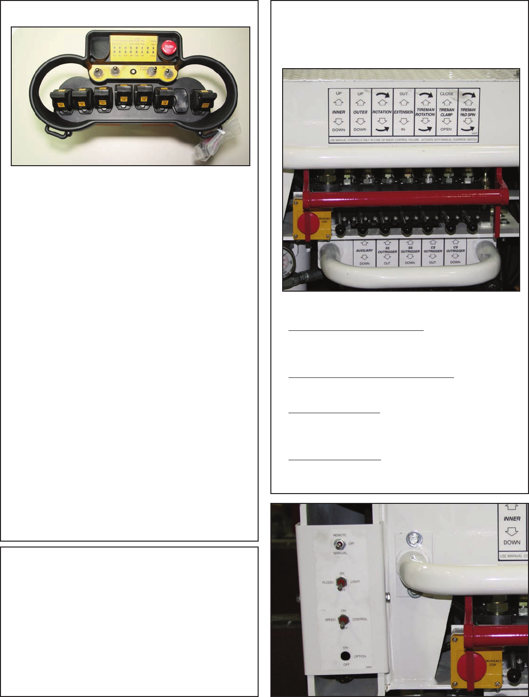
Radio Remote Operation
The crane is operated by a radio control system which
operates an electronic valve bank. The controller (as
shown above) operates the following functions:
Main Boom Up and Down
Outer Boom Up and Down
Extension Boom In and Out
Rotation Clockwise and Counter-Clockwise
TireMan Clockwise and Counter-Clockwise
TireMan Pad Clockwise and Counter-Clockwise
TireMan Open and Close
Note: If the crane does not operate, check the batteries
located in the remote handle and replace if necessary.
Start Up Procedure
For a more detailed version of this procedure, please see
the BMS-2 Remote Manual.
1. Be sure that all controls, joysticks or paddle levers are
in the Off (neutral) position. NOTE: If any control, joy-
stick or paddle lever is NOT in the Off (neutral) position
when the Start/Horn button is pushed, the transmitter
will not transmit.
2. Switch the transmitter "ON". A short buzzer signal will
sound.
3. Wait for the second buzzer signal (approx. 3 seconds).
4. Turn the E-Stop to release.
5. Press the Start/Horn button.
6. The green LED on the transmitter control panel will
flash.This indicates that the transmitter is working and is
ready to use.
7. Check that the machine functions correspond with
the transmitter functions. The receiver display will
change according to which motion is activated.
Note About Battery Condition
The batteries included with this equipment may be
rechargeable. To keep rechargeable batteries in
optimal working condition, follow these simple guidelines:
1. Keep battery away from moisture. Store in a cool, dry
location.
2. Do not store or carry battery so that metal objects
can contact exposed metal end. Keep battery cap
on when not in use.
3. The batteries should be recharged when they fail to
produce sufficient power.
4. Never attempt to open the battery for any reason.
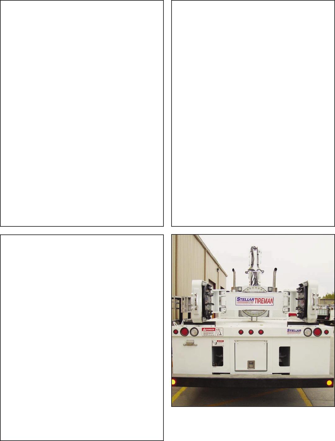
Manual Operation
In case of radio failure, the crane can be
operated using manual overrides located on the
valve bank.
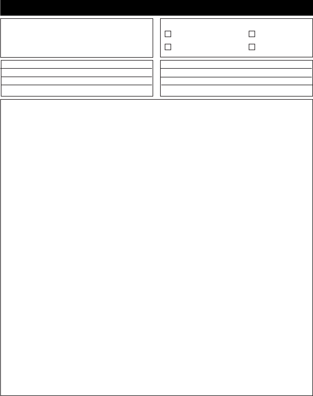
Valve Manual Override Operation
1. Switch to Manual Operation:
Flip the toggle switch (shown below) up to
“Manual”
2. Operate Levers on the Valve Bank:
Push or pull levers to operate listed function.
3. Switch Controls Off:
Flip the toggle switch to the middle “Off”
position.
4. Have Unit Serviced.
Operation
Crane Precautions
1. Movement of the control levers should be
slow and smooth to meter oil flow for safe
operation. Avoid jerky and sudden
movements.
2. The crane controls should be clearly marked
with decals. If these are missing or
illegible,replace immediately. (See Chapter
5: Decals)
3. Lift load slightly off the ground to check the
safety of the cargo. Do not use stability to
determine the safety. Consult the capacity
charts and strictly adhere to them.
4. Be constantly aware of the boom position
when operating the controls.
5. The boom tip should be centered directly
over the load before making the lift to avoid
swinging.
6. Do not drag loads with the crane.
7. Do not attempt to lift fixed loads.
8. Do not load boom in a sideways direction.
9. Know the weight of the rigging and load to
avoid overloading the crane.
10. Do not extend or rotate a load over
anyone.
11. Wear protective gear such as hard hat,
safety glasses, steel-toed boots, and gloves.
Crane Transport
Before transporting the crane, do the following:
1. The crane must be in the stored position.
2. Outriggers must be securely stowed and not
extended horizontally or vertically.
3. Hook and sheave assemblies must be
securely fastened to prevent swinging.
4. All loose accessories, tools, and remote
controls must be securely stored in their
respective compartments or fasteners.
5. The PTO must be disengaged.
6. The parking brake must not be released
until all of the above procedures are
completed.
7. Do not drive the carrier vehicle while a load
is present on the hook.
8. Do not drive the carrier vehicle with less
than proper tire inflation.
9. Do not drive the carrier vehicle in areas
where the vertical clearance is unknown.
10. Do not allow personnel to ride on the
equipment during transport.
The crane MUST be in the stored position before transporting.
Hook Precautions
1. Hooks are designed and manufactured to lift
specific loads. The specified rated load of a
hook applies to loads held uniformly in direct
tension and does not take into account
shock loads, hook tip loading, side loading,
bending, torsional, or related loads.
2. Do not attempt to lift a load that is larger
than the load rating of the hook.
3. Never use a hook’s yield point as an
indicator of its capacity.
4. Do not use a hook to lift personnel.
5. Know the rated load of the hook in use.
6. Never weld attachments to a finished hook
in field applications. This will alter and
destroy the design properties of the hook
material.
7. Keep fingers, hands, body, and loose
clothing from between the hook and the
load.
8. Avoid shock loading.
9. Inspect the hook regularly for excessive wear
and maintain it in safe operating condition.

28000 Owner’s Manual
OPERATOR REQUIREMENTS
1. Operation is limited to the following
people:
A. Designated individual.
B. Trainees under direct supervision
of the designated individual.
C. Test or maintenance individual.
D. Crane Inspector.
2. Operators must meet the following
physical qualifications:
A. Vision of at least 20/30 Snellen in
one eye and 20/50 in the other,
with or without corrective lenses.
B. Ability to distinguish colors if color
differentiation is required.
C. Adequate hearing, with or
without a hearing aid.
D. No physical or emotional defects
that may create a hazard to the
operator or others.
E. Normal depth perception and
coordination.
3. In addition to the physical qualifications,
Operators must:
A. Demonstrate the ability to
understand all decals, the
owner’s manual, and any other
information required for safe
operation of the crane.
B. Be able to demonstrate the ability
to safely control the crane.
C. Know all safety regulations.
D. Be responsible for maintenance
requirements.
E. Understand and be fully capable
of implementing all emergency
procedures.
F. Understand the operating
procedures as outlined by this
manual, ANSI B30.2, and
Federal/State Laws.
Operator Information
OPERATOR CONDUCT
1. Operators will not engage in any
operation that would cause them to divert
attention away from the operation of the
crane.
2. Operators are responsible for all
operations under their direct control.
3. Operators will not leave a suspended
load unattended.
4. Operators will be familiar with the
equipment and the maintenance required
for proper care.
HANDLING THE LOAD
1. Size of the load:
A. Do not load the crane beyond
the rated capacity.
B. It is the responsibility of the
operator to know the weight of
the handled load.
2. Attaching the load:
A. Attach the load to the hook by
means of slings or other approved
devices.
B. Do not wrap the hoist rope
around the load.
3. Moving the load:
A. Make certain that the crane is
level and properly blocked.
B. Ensure that the load is secure and
balanced within the sling before
moving it.
C. Be sure that the crane is stable
before moving the load. Use
stabilizer pads to ensure the
proper distribution of weight.
D. Do not drag the load sideways.
E. Make sure the hook is brought
over the load to minimize
swinging.
F. No suspended load should pass
over a person.
G. Avoid sudden starts and stops
when moving a load.

Maintenance
Chapter 3 - Maintenance
WARNING - Read the Following before
performing any maintenance on the
crane.
1. Only authorized service personnel are
to perform maintenance on the crane.
2. Disengage the PTO before any service
or repair is performed.
3. Do not disconnect hydraulic hoses
while there is still pressure in those
components.
4. Before disconnecting hydraulic
components, place the boom on the
ground or have it supported, shut off the
engine, release any air pressure on the
hydraulic reservoir, and move pedals
and control levers repeatedly through
their operating positions to relieve all
pressures.
5. Keep the crane and service body
clean and free from grease build-up, oil
and dirt to prevent slippery conditions.
6. Perform all safety and maintenance
checks before each period of use.
7. Replace parts with Stellar Industries, Inc.
approved parts only.
8. Immediately repair or have repaired
any components found to be
inadequate.
Maintenance Procedures
1. Position the crane where it will be out of
the way of other operations or vehicles in
the area.
2. Be sure boom is lowered to the ground or
otherwise secured from dropping.
3. Place all controls in the off position and
secure operating features from
inadvertent motion.
4. Disconnect power source.
5. Relieve hydraulic oil pressure from all
hydraulic circuits before loosening or
removing hydraulic components.
6. Label or tag parts when disassembling.
Periodic Inspection
Periodic Inspection should occur while the
crane is in use. For the duration of the
usage, inspect the crane for all of the
following:
1. Loose bolts and fasteners.
2. All pins, bearings, shafts, and gears for
wear, cracks, or distortion to include all
pivots, outriggers, sheave pins, and
bearings.
3. Hydraulic systems for proper operating
pressure.
4. Main frame mount bolts.
5. Cylinders for:
A. Damaged rods.
B. Dented barrels.
C. Drift from oil leaking internally.
D. Leaks at rod seals or holding valves.
6. PTO drive line system for proper
alignment, lubrication, and tightness.
7. Hydraulic hose and tubing for evidence of
damage such as blistering, crushing, or
abrasion.
Daily Inspection
Daily Inspection should occur each day
before the crane is put into use. Each day,
inspect the crane for all of the following:
1. Hydraulic oil level.
2. Loose parts or damage to structures or
weld.
3. Cylinder movement due to leakage.
4. Hoses and gearboxes for evidence of oil
leaks.
5. Controls, including hand throttle for
malfunction or adjustment.
6. Truck hand brake operation.
7. All securing hardware such as cotter pins,
snap rings, hairpins, and pin keepers for
proper installation.
8. All safety covers for proper installation.
9. Cylinder holding valves for proper
operation.
10. Wire rope for broken wires, extensive
wear, distortion, and heat damage.

28000 Owner’s Manual
Weekly Inspection
Weekly Inspection should occur at the
beginning of every work week. Each week,
inspect the crane for all of the following:
1. Lubrication of points required by
lubrication chart located in this chapter.
2. Proper operation of load hook safety
latch.
3. Presence of this owner’s manual.
Monthly Inspection
Monthly Inspection should occur at the
beginning of every work month. Each
month, inspect the crane for all of the
following:
1. Frame bolt tightness - turn barrel nuts and
mounting bolts during the first month of
operation on new machines and then
quarterly thereafter.
2. Cylinders and valves for leaks.
3. Lubrication.
4. Load hook for the following:
a. Cracks or having more than 5%
normal throat opening.
b. Any visible bend or twist from the
plane of the unbent hook.
5. Structural members for bends, cracks, or
broken members.
6. All welds for breaks and cracks.
7. All pins and keepers for proper installation.
8. All control, safety, and capacity placards
for readability and secure attachment.
9. Inspect all electrical wires and
connections for worn, cut, or deteriorated
insulation and bare wire. Replace or
repair wires as required.
10. Tightness of all boom wear, pad-retaining
bolts.
Service
The following general suggestions should
be helpful in analyzing and servicing your
crane. Using the following systematic
approach should be helpful in finding and
fixing problems:
1. Determine the problem.
2. List and record possible causes.
3. Devise checks.
4. Conduct checks in a logical order to
determine the cause.
5. Consider the remaining service life of
components against the cost of parts
and labor necessary to replace them.
6. Make the necessary repair.
7. Recheck to ensure that nothing has
been overlooked.
8. Functionally test the new part in its
system.
Stellar Industries recommends the first
filter change to occur after the first 250
hours of service.* The second, and
every subsequent change, should
occur after every 1,000 hours of
service. By following these guidelines,
the hydraulic oil should last up to
6,500 hours.
*Note: These recommendations are based on normal
working parameters. If operating in less than favorable
conditions (excessive dust, moisture, etc.), be sure to check
the filter gauge often for filter change notice.
Inspection Checklist
For a more detailed outline of scheduled
inspection points, refer to the Stellar
Inspection Checklist at the end of this
chapter. This list is an excellent guide for the
inspection tasks that will help maintain the
quality of your Stellar product. Feel free to
photocopy the checklist as needed.
ATTENTION
Every six (6) months, remove the
hydraulic pump from the PTO and
lubricate the splines using Chelsea
Lubricant #379831 or Stellar PN 20885.
Failure to lubricate shaft splines will cause
damage to the PTO and Hydraulic pump.

Maintenance
Engine Crankcase Apply Manufacturer’s
Recommendations
Hydraulic System
Below –5*F
-5*F to 90*F
Above 90*F
Reservoir
Petro-Canada Arctic MV 15 (ISO 22)
Petro-Canada HYDREX 32 (ISO 32)
Petro-Canada HYDREX 46 (ISO 46)
Open Gears Hand Precision XL3 Moly EP 2 (NLGI 2 grease
with moly)
Bearings, grease
(including turntable bearing
inner race)
Gun Precision XL EP 2 (NLGI 2)
Worm Drive Gearbox Gearbox Precision Synthetic EP 00 (NLGI 00)
Planetary Gearbox
(including winch)
Gearbox Traxon Synthetic 75W-90 (API GL-5)
Wear Pad Lubrication Spray Gearshield NC
Compressor Fluids
Reciprocating Single Stage
Reciprocating Double Stage
Crankcase
Crankcase
Compro 100 (ISO 100)
Compro 100 (ISO 100)
Lubrication Recommendations
Screw
-15˚F to 86˚F
-23˚F to 100˚F
32˚F to 113˚F
Crankcase
Compro XL-S 32 (ISO 32)
Compro XL-S 46 (ISO46)
Compro XL-S 68 (ISO68)
Component Location Recommendation
Greasing the Crane
Lubricate all grease gun points with
Extreme Pressure Grease - Stellar P/N: 22059.

28000 Owner’s Manual
Holding Valve Inspection Procedure
The cylinders are equipped with holding
valves that prevent sudden movement of
the cylinder rods in the event of a hydraulic
hose or hydraulic component failure. The
valve is checked in the following manner:
1. Identify the cylinder in question.
2. Identify the holding valves and the
cylinder direction in question.
a. Cylinder Extend.
b. Cylinder Retract.
3. Place the machine so that the cylinder
will be located in the appropriate testing
position.
4. Pick the load (Do not exceed capacity,
rated or stability).
5. Disengage hydraulics.
6. Operate crane functions.
A. If the cylinder creeps (lowering the
load), replace the holding valve.
B. If the cylinder does not creep (load
stays suspended), the valve is
operational.
Gear-Bearing Bolt Maintenance
Anytime a gear-bearing bolt is removed, it
must be replaced with a new bolt of the
identical grade and size. Once a bolt has
been torqued to 75% of its proof load and
then removed, the torque coefficient may
no longer be the same as when the bolt was
new thus giving indeterminate damp loads
after torquing.
Warning!
Failure to replace gear-bearing
bolts may result in bolt failure due
to metal fatigue causing serious
injury or even death.
Torque Data Chart
Note: For Crane Tie Down Rods, see
Chapter 6: Installation Overview.
When using the torque data in the charts
above, the following rules should be
observed.
1. Bolt manufacturer’s particular
specifications should be consulted when
provided.
2. Flat washers of equal strength must be
used.
3. All torque measurements are given in
foot-pounds. To convert to inch-pounds,
multiply by 12.
4. Torque values specified are for bolts with
residual oils or no special lubricants
applied. If special lubricants of high stress
ability, such as Never-Seez compound
graphite and oil, molybdenum disulphite,
colloidal copper or white lead are
applied, multiply the torque values in the
charts by the factor .90. The use of Loctite
does not affect the torque values listed
above.
5. Torque values for socket-head capscrews
are the same as for Grade 8 capscrews.
Plated
(Ft-Lb)
22
39
63
96
139
192
340
549
823
1167
1646
2158
2865
Plated
(Ft-Lb)
18
33
52
80
115
160
280
455
680
965
1360
1780
2370
Plain
(Ft-Lb)
25
44
70
105
155
220
375
605
910
1290
1815
2380
3160
Plated
(Ft-Lb)
13
23
37
57
82
115
200
295
445
595
840
110
1460
Plain
(Ft-Lb)
17
31
49
75
110
150
265
395
590
795
1120
1470
1950
Bolt DIA
(Inches)
0.3125
0.3750
0.4375
0.5000
0.5625
0.6250
0.7500
0.8750
1.000
1.1250
1.2500
1.3750
1.500
Size
(DIA-TPI)
5/16-18
3/8-16
7/16-14
1/2-13
9/16-12
5/8-11
3/4-10
7/8-9
1-8
1 1/8-7
1 1/4-7
1 3/8-6
1 1/2-6
Grade 5 Grade 8 Grade 9
Maintenance
Owner/Company:
Contact Person:
Crane Make/Model:
Crane Serial:
Type of Inspection (check one)
Inspection Checklist
Use of this checklist is subject to terms of the
Stellar Warranty information. Additional copies of
this checklist can be obtained by contacting
Stellar Customer Service at (800) 321-3741.
Date Inspected:
Hour Meter Reading:
Inspected by: (print)
Signature of Inspector:
Daily (if deficiency found)
Monthly
Quarterly
Annual
Type of Inspection Information
Daily and monthly inspections are to be performed by a “designated” person, who has
been selected by the employer or the employer’s representative as being competent to
perform specific duties.
Quarterly and annual inspections are to be performed by a “qualified” person who, by
possession of a recognized degree in an applicable field or certificate of professional
standing, or who, by extensive knowledge, training and experience has successfully
demonstrated the ability to solve or resolve problems related to the subject matter and
work.
One hour of normal crane operation assumes 20 complete cycles per hour. If operation
exceeds 20 cycles per hour, inspection frequency should be increased accordingly.
Consult the Stellar Owner’s Manual for additional inspection items.
Before inspecting and operating the crane, make certain that t he crane is set up away
from power lines and leveled with outriggers fully extended.
Daily (D): Before each day of operation, those items with a (D) must be inspected. This
inspection need not be recorded unless a deficiency is found.
Monthly (M): Monthly inspections or 100 hours of normal operation (which ever comes
first) includes all daily and monthly inspection items plus items designated with a (Q). This
inspection must be recorded.
Quarterly (Q): Every three months or 300 hours of normal operation (which ever comes
first) includes all daily and monthly inspection items plus items designated with an (M).
This inspection must be recorded.
Annual (A): Each year or 1200 hours of normal operation (which ever comes first) includes
all items on this form which encompasses daily, monthly, and quarterly inspections plus
those items designated by (A). this inspection must be recorded.

28000 Owner’s Manual
Daily Inspection
Frequency
D
D
D
D
D
D
D
D
D
D
D
D
D
D
Key
Decals
Controls
Station
Hydsystem
Hook
Rope
Pins
General
Operation
Remote Ctrls
Electrical
Anti 2-Blocking
Operation Aid
Operation Aid
Inspection Description
All load charts, safety & warning Decals, & control Decals are present and
legible.
Check all safety devices for proper operation.
Control mechanisms for proper operation of all functions, leaks, & cracks.
Control mechanisms for proper operation of all functions, leaks, & cracks.
Hydraulic system (hoses, tubes, & fittings) for leakage & proper oil level.
Presence & proper operation of hook safety latches.
Proper reeving of wire rope on sheaves & winch drum.
Proper engagement of all connecting pins & pin retaining devices.
Overall observation of crane for damage or missing parts, cracked welds &
presence of safety covers.
During operation, observe crane for abnormal performance, unusual wear.
If observed, discontinue use & determine cause & severity of hazard.
Operate remote control devices to check for proper operation.
Operate all lights, alarms, etc. to check for proper operation.
Operate anti 2-blocking device to check for proper operation.
Check presence of boom angle indicator.
Check overload device for proper operation.
Status

Maintenance
Monthly Inspection
Frequency
M
M
M
M
M
M
M
M
M
M
M
M
M
M
M
M
M
M
M
M
M
M
Key
Daily
Cylinders
Valves
Valves
Valves
General
Electrical
Structure
Welds
Pins
Hardware
Wear Pads
Pump & Motor
PTO
Hyd Fluid
Hyd Lines
Hook
Rope
Manual
Chassis
Chassis
Station
Inspection Description
All Daily Inspections.
Visual inspection of cylinders for leakage at rod, fittings, & welds. Damage
to rod & case.
Holding valves for proper operation.
Control valve for leaks at fittings & between sections.
Control valve linkages for wear, smoothness of operation & tightness of
fasteners. Relief valve for proper pressure settings.
Bent, broken or significantly rusted/corroded parts.
Electrical systems for presence of dirt, moisture & frayed wires.
All structural members for damage.
All welds for breaks & cracks.
All pins for proper installation & condition.
All bolts, fasteners & retaining rings for tightness, wear & corrosion.
Condition of wear pads.
Hydraulic pumps & motors for leakage at fittings, seals & between sections.
Check tightness of mounting bolts.
Transmission/PTO for leakage, abnormal vibration & noise, alignment &
mounting bolt torque.
Quality of hydraulic fluid and for presence of water.
Hoses & tubes for leakage, abrasion damage, blistering, cracking,
deterioration, fitting leakage, & secured properly.
Load hook for abnormal throat distance, twist, wear, & cracks.
Condition of load line.
Presence of operator's manuals with the unit.
Tire wear and air pressure.
Working backup alarm.
Fire extinguisher at cab or machinery housing.
Status

28000 Owner’s Manual
Quarterly Inspection
Frequency
Q
Q
Q
Q
Q
Q
Key
Daily
Monthly
Rotation Sys
Hardware
Structure
Hardware
Inspection Description
All daily inspections.
All monthly inspections.
Rotation bearing for proper torque of all mounting bolts.
Base mounting bolts for proper torque.
All structural members for deformation, cracks, & corrosion.
Base
Outrigger beams & legs
Mast
Inner boom
Outer boom
Extension(s)
Jib boom
Jib extension(s)
Other
Other
Pins, bearings, shafts, gears, rollers, & locking devices for wear, cracks,
corrosion, & distortion.
Inner boom pivot pin(s) & retainer(s)
Outer boom pivot pin(s) & retainer(s)
Inner boom cylinder pin(s) & retainer(s)
Outer boom cylinder pin(s) & retainer(s)
Extension cylinder pin(s) & retainer(s)
Jib boom pin(s) & retainer(s)
Jib cylinder pin(s) & retainer(s)
Jib extension cylinder pin(s) & retainer(s)
Boom tip attachments
Other
Other
Status

Maintenance
Quarterly Inspection Continued...
Frequency
Q
Q
Q
Q
Q
Q
Key
Hyd Lines
Pumps&Motors
Valves
Cylinders
Winch
Hyd Filter
Inspection Description
Hoses, fittings, & tubing for proper routing, leakage, blistering, deformation,
& excessive abrasion.
Pressure line(s) from pump to control valve
Return line(s) from control valve to reservoir
Suction line(s) from reservoir to pump
Pressure line(s) from control valve to each function
Load holding valve pipe(s) and hose(s)
Other
Pumps and motors for loose bolts/fasteners, leaks, noise, vibration, loss of
performance, heating and excess pressure.
Winch motor(s)
Rotation motor(s)
Other
Hydraulic valves for cracks, spool return to neutral, sticking spools, relief
valve failure.
Main control valve
Load holding valve(s)
Outrigger or auxiliary control valve(s)
Other
Hydraulic cylinders for drifting & leakage. Rods for nicks, scores, & dents.
Castor damage. Case & rod ends for damage & abnormal wear.
Outrigger cylinder(s)
Inner boom cylinder(s)
Outer boom cylinder(s)
Extension cylinder(s)
Rotation cylinder(s)
Jib lift cylinder(s)
Jib extension cylinder(s)
Other
Winch, sheaves, & drums for damage, abnormal wear, abrasion, & other
irregularities.
Hydraulic filters for replacement per maintenance schedule.
Status

28000 Owner’s Manual
Annual Inspection
Frequency
A
A
A
A
A
A
A
A
A
A
A
A
A
A
A
Key
Daily
Monthly
Quarterly
Hyd System
Controls
Valves
Valves
Rotation Sys
Lubrication
Hardware
Wear Pads
Loadline
Historic Data
Historic Data
Historic Data
Inspection Description
All daily inspection items.
All monthly inspection items.
All quarterly inspection items.
Hydraulic fluid change per maintenance schedule.
Control valve calibration for correct pressures & relief valve settings.
Safety valve calibration for correct pressures & relief valve settings
Valves for failure to maintain correct settings.
Rotation drive system for proper backlash clearance & abnormal wear,
deformation, & cracks.
Gear oil change in rotation drive system per maintenance schedule.
Check tightness of all fasteners and bolts.
Wear pads for excessive wear.
Loadline for proper attachment to drum.
Monthly inspection records.
Maintenance records.
Repair and modification records.
Status

Maintenance
Inspection Notes
28000 Owner’s Manual

Specifications
Chapter 4 - Specifications
Model 28000 Crane
SPECIFICATION SHEET
Crane Rating: 280,000 ft-lbs (38.71 ton meters)
Standard Boom Length: 13’ 2” (4.01 m) from CL of Crane
Boom Extension: Hydraulic 37" (94.0 cm)
Maximum Horizontal Reach: 16’ 3” (4.95 m) from CL of Crane
Maximum Vertical Lift: 25’ (7.62 m)
(From Truck Frame)
Cylinder Specifications
Inner Lift Cylinder: 9” (22.9 cm) bore with integral pilot
operated counterbalance valves.
Outer Lift Cylinder: 7” (17.8 cm) bore with integral pilot
operated counterbalance valves.
Extension Cylinder: 6” (15.2 cm) bore with integral pilot
operated counterbalance valves.
Rotation: 315 degree power
(planetary gear with pinion)
Lifting Capacities: 28,000 lbs @ 10’ (12,700 kg @ 3.05 m)
(From CL of Truck) 17,200 lbs @ 16’ 3” (7,800 kg @ 4.95 m)
Power Supply Required: PTO & Pump
(16 gpm @ 4,200 psi)
(60 lpm @ 290 bars)
Controls: Fully Proportional Paddle Controls for all
functions.
Stowed Height: 114” (289.6 cm)
(Above Truck Frame)
Mounting Space Required: 48” (121.9 cm)
Approximate Shipping Weight: 13,000 lbs (5,895 kg)
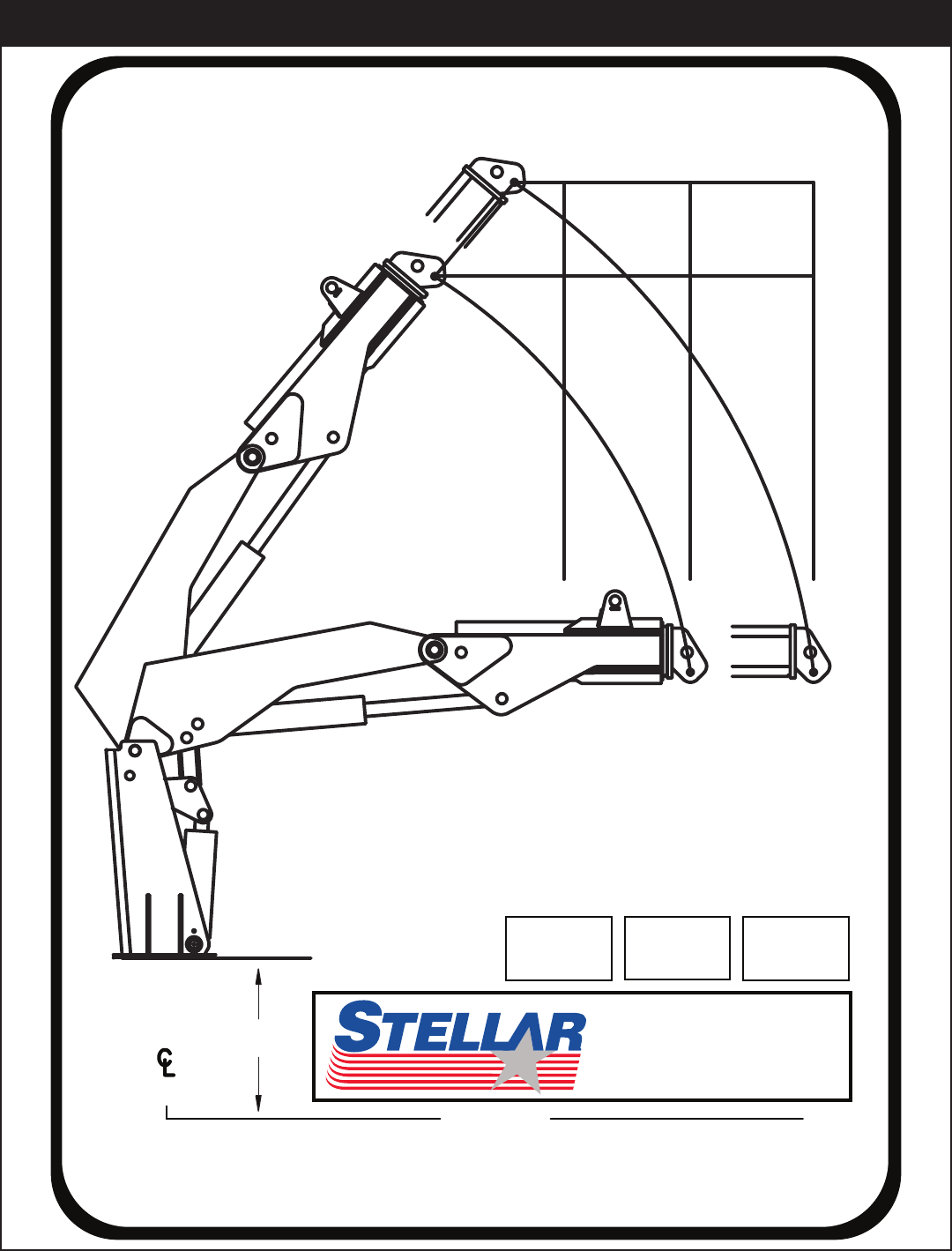
28000 Owner’s Manual
10’
3.05m
16’3”
4.95m
13’2”
4.01m
10’
3.05m
16’3”
4.95m
13’2”
4.01m
12’9”
3.89m
25’
7.62m
22’6”
6.86m
CAPACITY
CHART
28000 lbs
12700 kg
21300 lbs
9660 kg
17200 lbs
7800 kg
0’
0m
TRUCK
GROUND 0’
0m
16055
190 STATE STREET GARNER, IA 50438
PHONE: (800) 321-3741 FAX: (641) 923-2812
28000
66.00”
(167.6cm)
®
Capacity Chart - Decal PN 16055

Decals
Operation Hazard Decal
Function: To inform the opera-
tor and other personnel in the
work area of the hazard associ-
ated with improper maintenance
and unauthorized modifications,
the possible consequences
should the hazard occur, and
how to avoid the hazard.
PN: 4190
Operation Hazard Decal
Function: To inform the opera-
tor of the need for proper train-
ing, familiarity with safe operat-
ing procedures, and the possi-
ble consequences of operation
without training.
PN: C4544
Operation Hazard Decal
Function: To inform the opera-
tor of the hazard associated
with overloading the crane, the
possible consequences should
the hazard occur, and how to
avoid the hazard.
PN: 4189
Operation Hazard Decal
Function: To inform the opera-
tor of the need for proper train-
ing, familiarity with safe operat-
ing procedures and , the possi-
ble consequences without train-
ing.
PN: C4540
Moving Boom Hazard Decal
Function: To inform the opera-
tor and other personnel in the
work area of the hazard associ-
ated with a moving boom, espe-
cially while stowing and unfold-
ing the crane, the possible con-
sequences should the hazard
occur, and how to avoid the haz-
ard. PN: C4541
Foot Crush Hazard Decal
Function: To inform the opera-
tor and other personnel in the
work area of the hazard associ-
ated with the operation of the
outriggers, the possible conse-
quences should the hazard
occur, and how to avoid the
hazard. PN: C4795
Decals of Note
Chapter 5 - Decals
28000 Owner’s Manual
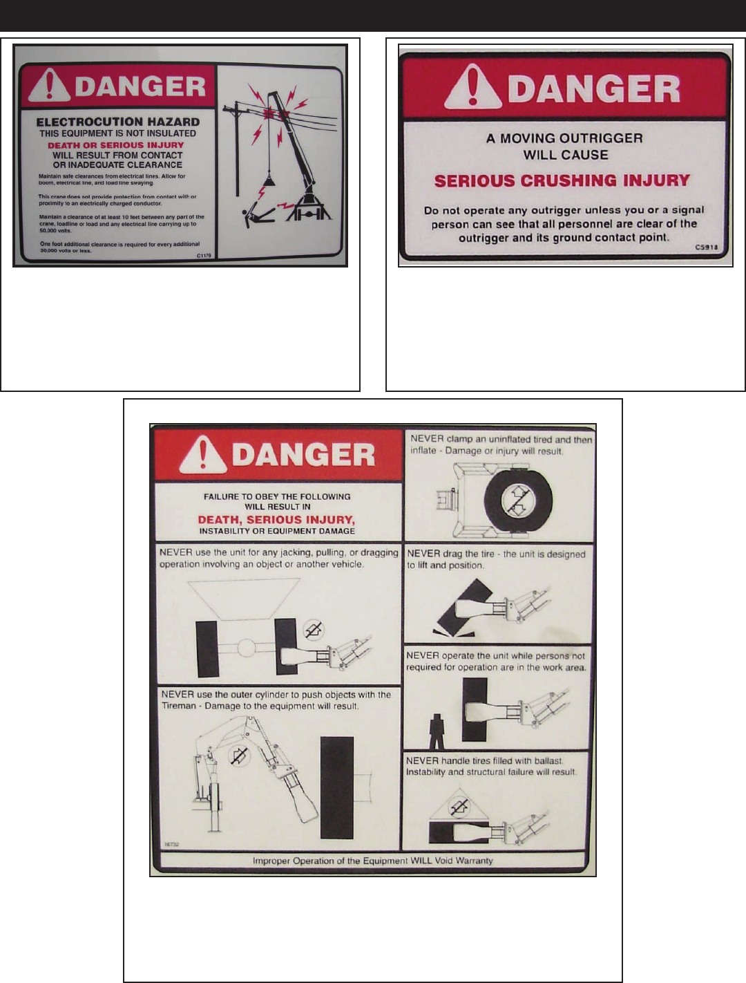
Electrocution Hazard Decal
Function: To inform the operator and other personnel
in the work area of the hazard associated with contact
or proximity to electrical lines, the possible conse-
quences should the hazard occur and how to avoid
the hazard. PN: C1179
Moving Outrigger Hazard Decal
Function: To inform the operator of the hazard asso-
ciated with outrigger operation, the possible conse-
quences should the hazard occur, and how to avoid
the hazard. PN: C5918
Tire Man Hazard Decal
Function: To inform the operator and other personnel in the work area
of the hazard associated with improper use of the Tire Man, the possi-
ble consequences should the misuse occur and how to avoid these
hazard.
PN: 16732
Decals of Note Continued...
Decals
Decal Kit - PN 16658
207 C1179 DECAL-DANGER ELECTROCUTION HORTL
DECAL- 28000 IDENTIFICATION
DECAL-DANGER OPERATION RESTRICTION
DESCRIPTION
DECAL-DANGER OPERATION CONDITION
PART No.ITEM
01 54597
THESE DECALS NOT SHOWN
PN 16658
(USE WITH BODY PACKAGE)
03 C4540
02 16055
04 4189
DECAL-DANGER
DECAL-CAPACITY
05 C4544
06 4190
DECAL-CAUTION
QTY
2
1
2
1
1
1
DECAL- TIRE MAN OVERLOAD POSITION
DECAL-GEARBOX OIL LEVEL
DECAL-GREASE WORM DRIVE
DECAL-AIR DRAIN
DECAL-DANGER FOOT
DECAL-CAUTION STAND CLEAR
DECAL SWITCH PANEL 28000 CRANE
DECAL-OUTRIGGER 28,000
DECAL-SWITCH PLATE 28,000
DECAL-DANGER ELECTROCUTION
DECAL-VB CONTROL 28000
DECAL STELLAR LOGO 4.00X9.50
DECAL-EXPLODING TANK
DECAL-STELLAR LOGO 2.00X4.50
DECAL-CONTROL HANDLE 28,000
DECAL-STELLAR ATTACHMENTS
DECAL ASME/ANSI B30.22/B30.5
C591118
10 C4795
08 C5918
09 C4541 DECAL-WARNING
11 4214
12 16620
DECAL-SERVICE
14 36248
13 43470
15 C4545
16 8998
17 8843
19 C5910
20 16657
22 43469
21 15172
23 16973
2261925
24 22618
26 16732
2
2
2
2
1
1
1
1
4
1
1
1
1
1
1
2
1
1
2
27 47404 DECAL COUPLERS 23000 1
28 54589 DECAL STELLAR LOGO 8.00x22.25 2
21
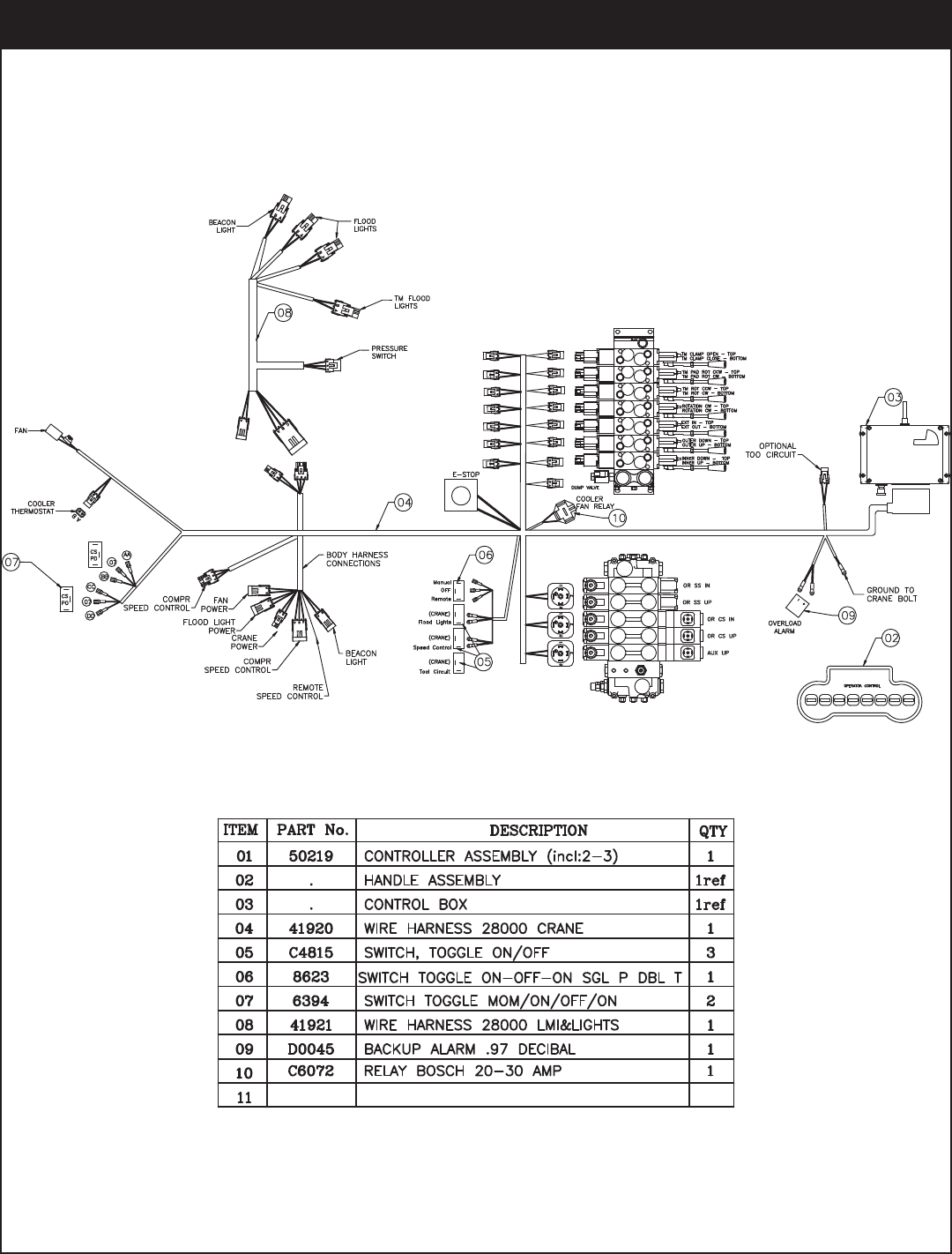
OPERATOR CONTROL
12
SS CS
14
23
26 26
25
9
10
22
24
7
11
8
6
4
35
2
10
8
7
9
2
20
13
27
28 1
The following chapter highlights many decals of note on your Stellar 28000 and possibly
the TM14160. For a complete list of decals, please refer to the Decal Placement drawing
below. Remember: Decals are considered safety equipment. They must be maintained,
as would other safety devices. Do not remove any decals. Replace any decals that are
missing, damaged, or not legible.
28000 Owner’s Manual
Installation
General Installation
This chapter is designed to serve as a general guide
for the installation of a Stellar 28000 Articulating
Crane on a Stellar Service Body. Each installation is
considered unique so certain portions of this chapter
may or may not apply to your direct application. If a
question should arise during the installation process,
please contact Stellar Customer Service at (800) 321
3741.
This crane is designed for use with a Stellar Service
Body installed on a vehicle that meets the minimum
chassis requirements of the crane. Check with Stellar
Industries before installing this crane on a body other
than a Stellar Service Body.
WARNING!
The use of this crane on a body not
capable of handling the loads imposed on
it may result in serious injury or death.
Installation Notice
According to Federal Law (49 cfr part 571), each
final-stage manufacturer shall complete the vehicle
in such a manner that it conforms to the standards in
effect on the date of manufacture of the incomplete
vehicle, the date of final completion, or a date
between those two dates. This requirement shall,
however, be superseded by any conflicting provisions
of a standard that applies by its terms to vehicles
manufactured in two or more stages.
Therefore, the installer of Stellar cranes and bodies is
considered one of the manufacturers of the vehicle.
As such a manufacturer, the installer is responsible for
compliance with all applicable federal and state
regulations. They are required to certify that the
vehicle is in compliance with the Federal Motor
Vehicle Safety Standards and other regulations issued
under the National Traffic and Motor Vehicle Safety
Act.
Please reference the Code of Federal Regulations,
title 49 - Transportation, Volume 5 (400-999), for further
information, or visit
http://www.gpoaccess.gov/nara/index.html for the
full text of Code of Federal Regulations.
Notice:
PTO and Pump installation instructions are provided
by the corresponding manufacturers. For more
information on which PTO and Pump fit your
application, please contact your local Stellar
Distributor or Stellar Customer Service.
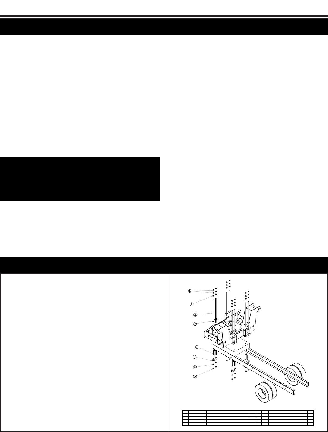
Notice: Read this Page Before Installation of the Crane
For more detail, please contact
Stellar Customer Service
1. Relocate any obstructions on the frame that will be in the
way of mounting the crane.
2. Measure the inside of the frame rails and cut the frame
support to this length. Ensure that the frame supports have
a tight fit between the frame rails.
3. Set the crane on the chassis and allow a minimum of 2”
from the cab.
4. Install the crane tie downs. Start at one corner and tighten
both tie downs to 200 ft-lbs. Move to the diagonal set and
tighten to 200 ft-lbs. Tighten the remaining 2 corners.
Continue this pattern at 200 ft-lb increments until 650-700 ft-
lbs is achieved. Be sure the mounting block stays
perpendicular to the frame rail as they are tightened
down.
5. Connect the pressure and return lines per the hydraulic kit.
6. Connect the (+12V) power and ground wires.
7. Check the reservoir for oil and fill if necessary.
8. Operate the crane for several cycles.
.YTQNOITPIRCSEDTRAPMETI.YTQNOITPIRCSEDTRAPMETI
8GNIKCOL POT 8RGHH 7-52.1 TUN43885400051 KCOLB GTM45081
2 11677 PLATE MOUNTING 23000 4 6 8978 NUT 1.25-7 HHGR8 16
4ENARC 00051 TROPPUS EMARF202878DOR NWOD EIT894413
49180 WASHER 1.25 SAE FLAT YELLOW GR8 16
PN 16659
Installation Overview
See the next page
for a larger view
Chapter 6 - Installation
28000 Owner’s Manual
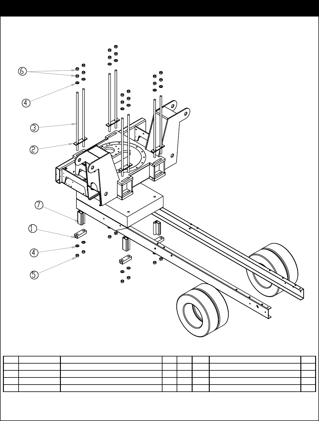
.YTQNOITPIRCSEDTRAPMETI.YTQNOITPIRCSEDTRAPMETI
8GNIKCOL POT 8RGHH 7-52.1 TUN43885400051 KCOLB GTM45081
2 11677 PLATE MOUNTING 23000 4 6 8978 NUT 1.25-7 HHGR8 16
4ENARC 00051 TROPPUS EMARF202878DOR NWOD EIT894413
49180 WASHER 1.25 SAE FLAT YELLOW GR8 16
PN 16659
Mounting Kit Drawing 16659
Assembly Drawings
2
3
35
42
16 17
18
20
5
7
6
12
14
8
11
13
15
9
19
1
23
22
38
21
10
24
37
4
32
10
9
29
6
30 31
7
27
7
26
10
25
28
27
36
27
6
33
7
34
28
7
39
NOTE: RADIO RECEIVER AND ALARM SHOWN
FOR REFERNECE
9
7
7
7
41
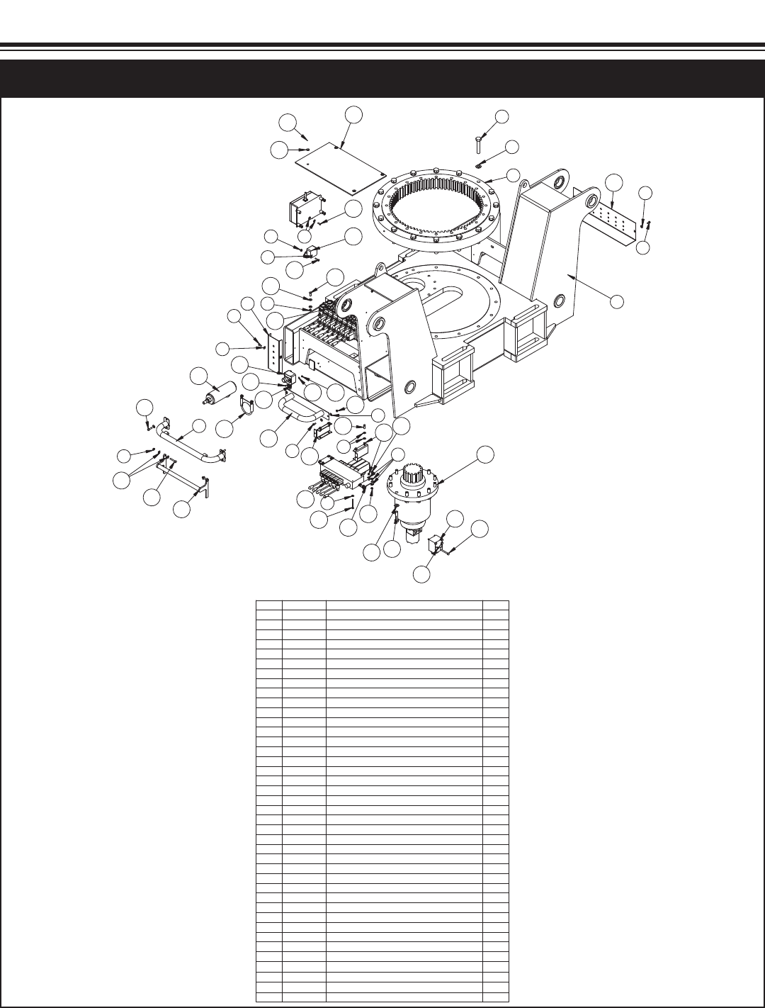
PN 47880
esaBNOITPIRCSEDTRAPMETI
100082 ESAB686841
2 18471 TURNTABLE BEARING 230001
3 18041 WASHER 0.88 SAE FLAT YELLOW GR916
4 17962 CAP SCR 0.88-9X4.50 HHGR9 ZY16
5 41336PC PLATE SWITCH MTG 230001
6 0479 CAP SCR 0.25-20X0.75 HHGR56
24TALF 52.0 REHSAW04307
100032 BV DRAUGCP480148
7COLYN HH 81-13.0 TUN24309
10 0343 WASHER 0.31 USS FLAT ZINC18
11 0485 CAP SCR 0.31-18X1.25 HHGR54
12 22921 E-STOP PANIC BAR 280001
100032 CINAP RAB2801431
14 22183 CAP SCR #8-32X0.75 BTNHD SS2
15 0488 CAP SCR 0.31-18X2.00 HHGR52
16 C6219 WASHER 0.75 SAE FLAT YELLOW GR812
17 C1028 CAP SCR 0.75-10X3.00 HHGR8 ZY12
18 22935VALVE BLOCK CBCA-LAN-XTS 1
19 5591WASHER 0.31 SAE FLAT YELLOW GR84
20 C0930 CAP SCR 0.31-18X3.00 HHGR54
21 40827 VB 5 SECT HYDRO CONTROL HC-D3M/51
100032 AGNIZ RETLIF8331422
23 41339 CLAMP ZINGA FILTER 230001
24 0420 CAP SCR 0.31-18X0.75 HHGR54
200032 TNM BV TEKCARBCP9704452
26 0482 CAP SCR 0.25-20 X 3.00 HHGR54
27 0333 NUT 0.25-20 HHGR5 NYLOC 15
28 0480 CAP SCR 0.25-20X1.00 HHGR58
29 44511 GUARD OUTRIG VB 230001
2SS TALF 91.0 REHSAW5812203
2SS COLYN HH 23-8# TUN6812213
32 C0922 CAP SCR 0.31-18X1.00 HHGR53
33 47425 CAP SCR 6MMX20MM HH CLASS 8.8 4
34 44078PC BRACKET VB MNT BASE 230002
100032 REVOC ETALPCP7331453
36 36243PC PLATE SWITCH MTG 28000 CRANE1
37 0437 CAP SCR 0.25-20X1.25 HHGR52
38 42802 VB 7 SECT DANFOSS PVG321
41 12869 STRAIN RELIEF .50 NPT .24-.47 CABLE1
42 60505 GEAR BOX W/MOTOR 23/280001
Base Assembly - PN 47880
Chapter 7 - Assembly Drawings
28000 Owner’s Manual
14 4
5
1
3
2
6
7
9
8
10
12
11
2
13
4
5
15
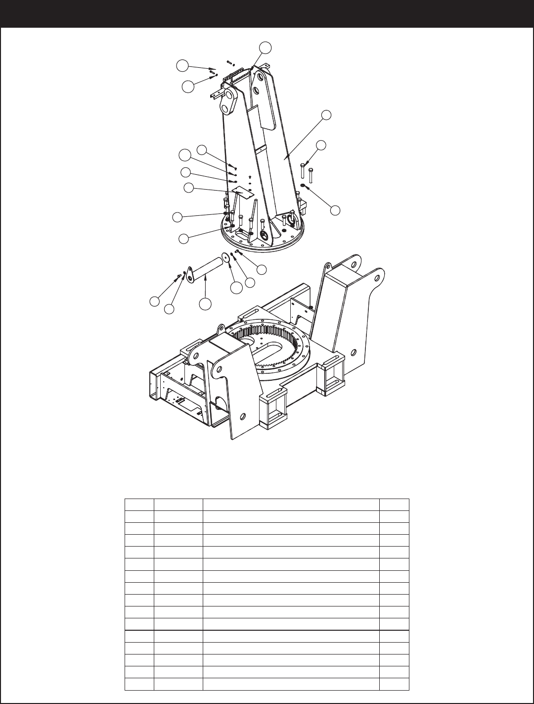
PN 18073
.YTQNOITPIRCSEDTRAPMETI
100082 TSAM304511
2 18041 WASHER 0.88 SAE FLAT YELLOW GR918
3 17963 CAP SCR 0.88-9X3.50 HHGR9 ZY16
28RG TALF 05.0 REHSAW0970D4
5 10172 CAP SCR 0.50-13X1.00 HHGR8 ZY2
6 17964 CAP SCR 0.88-9X5.50 HHGR82
7 11297 PLATE INSPECTION MAST 230001
8 0484 CAP SCR 0.31-18 X 0.50 HHGR5 2
9 0343 WASHER 0.31 USS FLAT ZINC2
100082 PMALC ESOH3317101
11 11882 CAP SCR 0.38-16X1.75 SH ZC2
2KCOL 83.0 REHSAW325021
13 15755ZP PIN TEAR DROP 3.00X16.13 1
191.0X00.4X65.0 PAC NIP5133141
2KCOL 13.0 REHSAW225051
Mast Assembly - PN 18073
Assembly Drawings
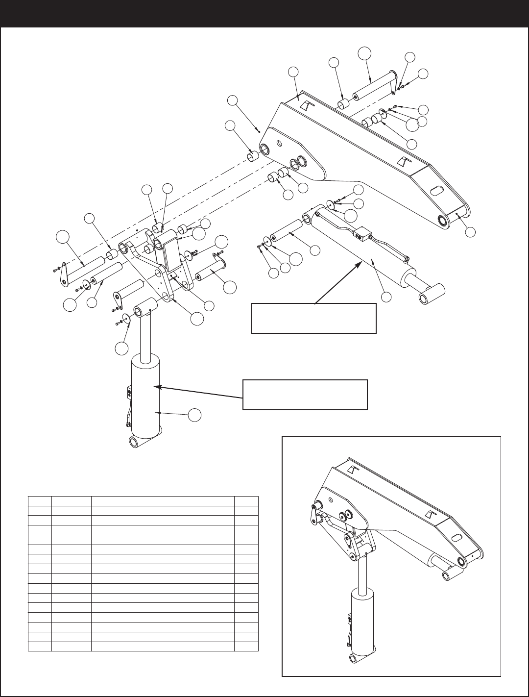
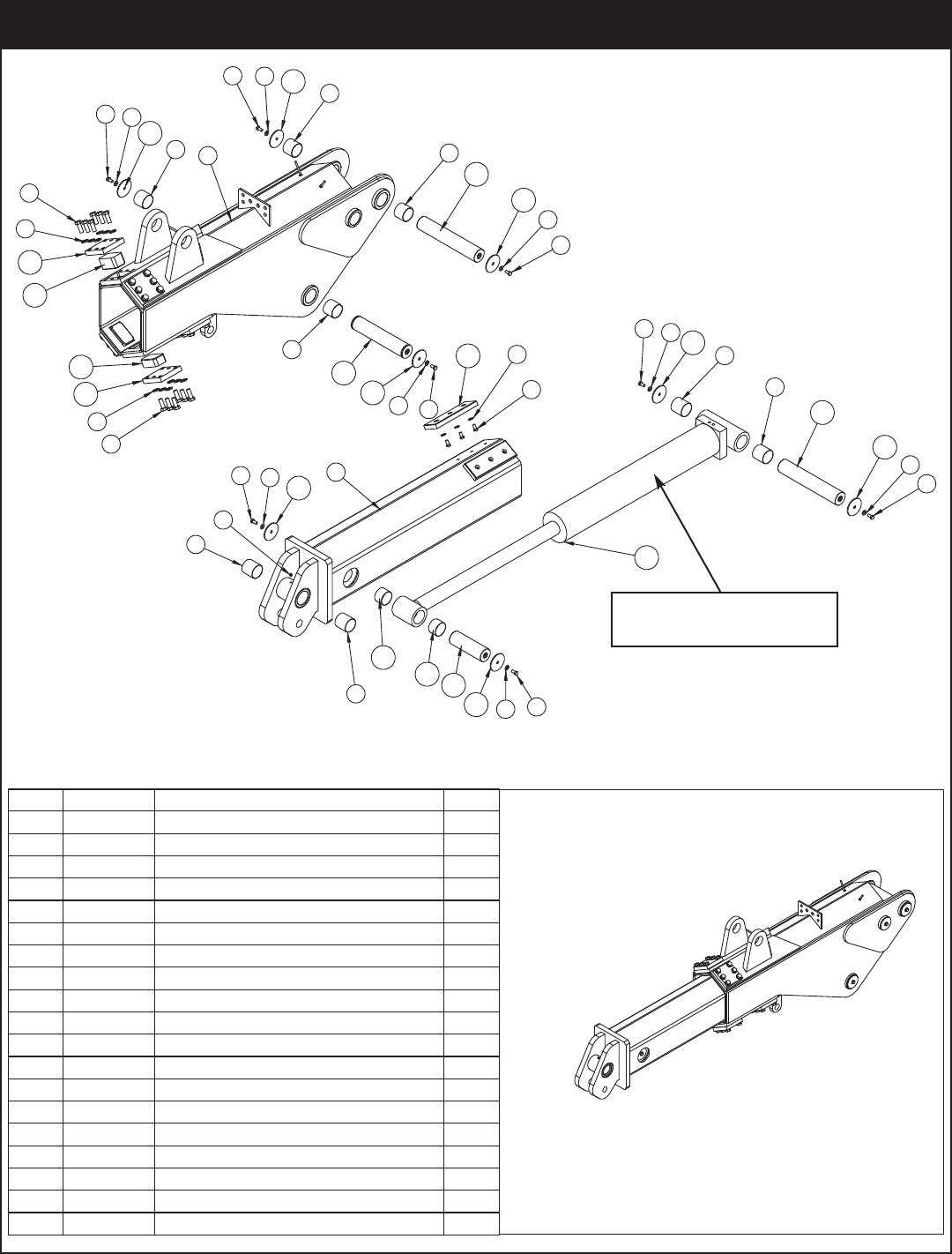
ITEMPART DESCRIPTIONQTY.
PN 55106
1 55103INNER BOOM 28000 REVISED 1
2 50628 CYLINDER ASM 7.00X38.25 1
3D0790WASHER 0.50 SAE FLAT YELLOW GR810
4 10172 CAP SCR 0.50-13X1.00 HHGR810
5c1592 ZERK 1/8 NPT STRAIGHT5
6 2227 BUSHING 48DXR48 GARLOCK6
7 0865 BUSHING 48DXR32 GARLOCK4
8 54374 BUSHING COMPOSITE MRP 3.00X2.504
9 41063ZPPIN 3.00X14.00 D&T 2
10 13315PIN CAP 0.56X4.00X0.19 6
11 15497 LINK WLDMT 28000 MAIN1
12 31056ZP PIN TEAR DROP 3.00X20.13 2
13 15495 LINK MAIN 280001
14 15763ZP TEAR DROP PIN 3.00X12.63 2
15 20694 CYLINDER ASM 28000 MAST 1
11
1
5
6
12 3
4
4
3
10
8
88
6
5
2
10
3
4
9
10
3
4
65
7
10
14
13
5
10
9
10
6
15
12
Main Boom Assembly - PN 55106
Note: Main Lift Cylinder uses
Stellar Seal Kit PN 35651
Note: Secondary Cylinder
uses Stellar Seal Kit PN 35650
28000 Owner’s Manual
3
2
4
5
5
4
6
2
3
1
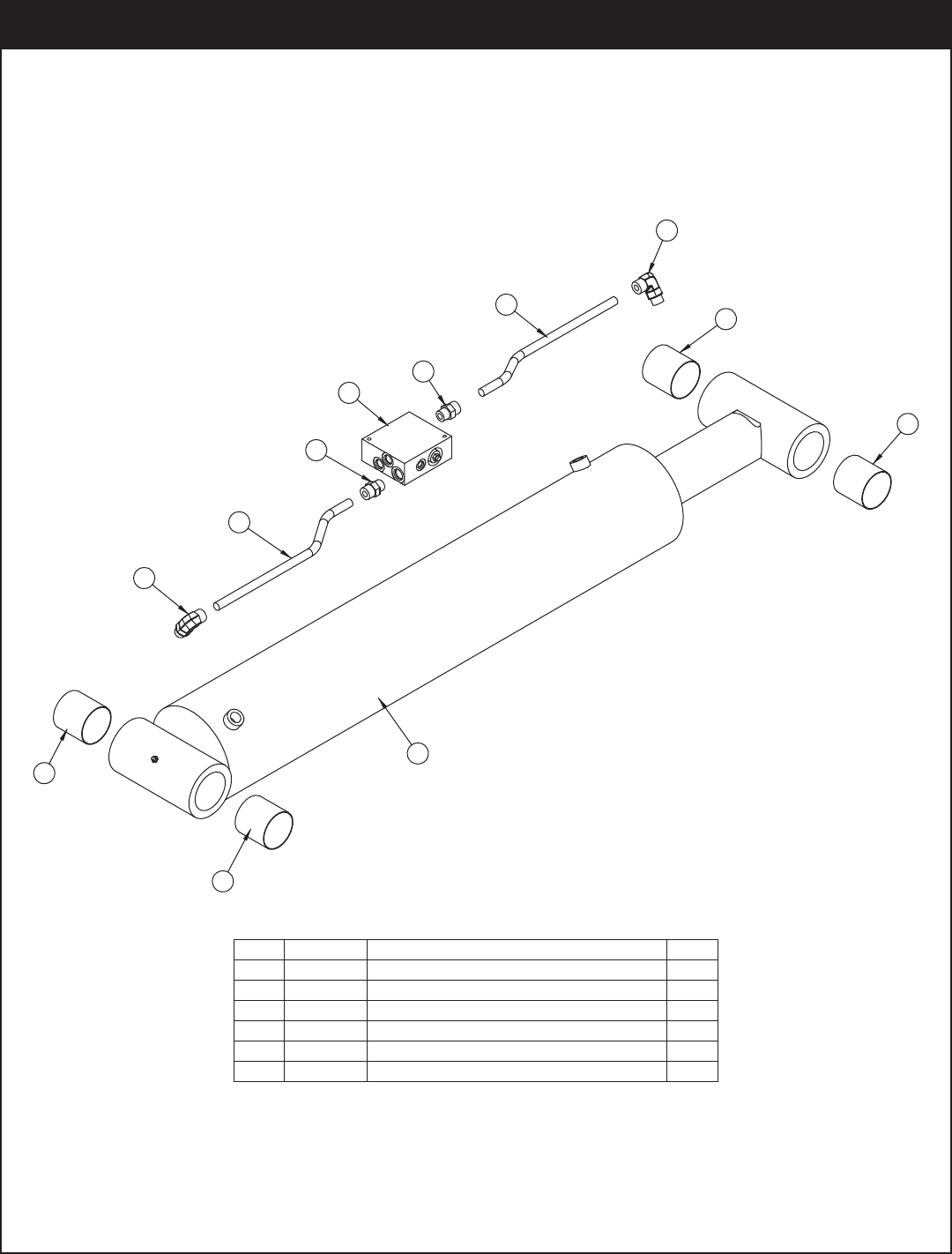
PRESSURE SWITCH
IN THIS PORT
ITEM NO.PART NO.DESCRIPTION QTY
115598 CYLINDER 9.00x4.00x21.81 1
2 16153 FTG ADAPT 10-C5OLO-S2
32227BUSHING 48DXR48 GARLOCK 4
4 16157 TUBE ASM 0.63X7.88 YZ 2
5 16152 FTG ADAPT 10-F5OLO-S2
6 15995 MANIFOLD ASM DUAL T2A 5000PSI1
PN 20694
Main Boom Cylinder Assembly - PN 20694
Assembly Drawings
11
5313 8
18
15
13
3
5
8
14
13 35
18 3
5
2
53
13
8
6
4
17
16
19
17
4
6
7
9
5313
9
10 12
13 35
5313 9
9
15
13
3
5
10
ITEMPART DESCRIPTIONQTY.
1 55107 OUTER BOOM 28000 REVISED1
2 15388EXT BOOM 280001
3D0790 WASHER 0.50 SAE FLAT YELLOW GR814
4C6219 WASHER 0.75 SAE FLAT YELLOW GR836
5 10172 CAP SCR 0.50-13X1.00 HHGR814
6 4543 CAP SCR 0.75-10X2.00 HHGR8 36
7c1592 ZERK 1/8 NPT STRAIGHT1
8 54374 BUSHING COMPOSITE MRP 3.00X2.504
9 2227 BUSHING 48DXR48 GARLOCK4
10 0865 BUSHING 48DXR32 GARLOCK2
11 15608 CYLINDER 6.00x37.001
12 15769ZPPIN 3.00X9.13 D&T 1
13 13315PIN CAP 0.56X4.00X0.19 8
14 26973ZPPIN 3.00X15.00 SR/D&T1
15 55109ZPPIN 3.00X16.88 D&T 2
16 15778 WEAR PAD 3.00X5.00X2.442
17 15609PCPLATE WEAR PAD COVER 280006
18 15601 WEAR PAD 1.00X4.00X12.002
19 15779 WEAR PAD 3.00X5.00X1.754
PN 55108
Extension Boom Assembly - PN 55108
Note: Cylinder uses Stellar
Seal Kit PN 35649
28000 Owner’s Manual
.YTQNOITPIRCSEDTRAPMETI
152.83X00.7 REDNILYC406511
2S-OLO5C-01 TPADA GTF351612
2 90.61X36.0 MSA EBUT851613
2S-OLO5F-01 TPADA GTF251614
5 15995 MANIFOLD ASM DUAL T2A 5000PSI 1
6 2227 BUSHING 48DXR48 GARLOCK 4
6
CYLINDER BUSHINGS SHOWN
FOR REFERENCE ONLY
1
6
6
2
3
4
5
4
3
2
6
PN 50628
Extension Boom Cylinder Assembly - PN 50628
Assembly Drawings
24
20
10
8
13
12
6
23
8
12
13
19
21
14
16
15
1
5
2
5
3
4
18
7
22
11
17
9
8
12
13
BASE WELDMENT SHOWN AS REFERENCE
24
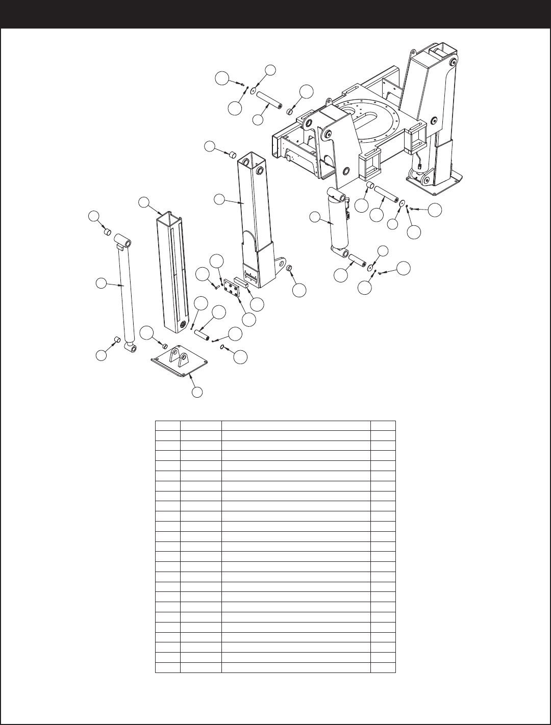
.YTQNOITPIRCSEDTRAPMETI
200032 REGGIRTUO054041
2 15502 OUTRIGGGER LEG 280002
200.05X00.4 REDNILYC49993
4 4381 BUSHING 32DXR32 2.00X2.00 GARLOCK4
5 0635 BUSHING 40DXR32 GARLOCK8
248384 MSA REDNILYC383846
7 40837 OUTRIGGER PAD 23000 96IN2
8 8377PIN CAP 0.56X3.50X0.19 12
2T&D 88.41X05.2 NIPPZ954049
2 T&D 00.41X05.2 NIPPZ5838401
400.2 EDISNI GNIR PANS752211
218RG TALF 05.0 REHSAW0970D21
13 10172 CAP SCR 0.50-13X1.00 HHGR8 ZY12
14 10180PC COVER WEAR PAD 230002
15 C5902 WASHER 0.63 SAE FLAT YELLOW GR812
16 C1025 CAP SCR 0.63-11X2.00 HHGR8 ZY12
17 25574 BUSHING 40DXR20 2.50X1.254
261-5323-ISQ GNIHSUB918881
19 13343 BUSHING 40DXR16 GARLOCK4
20 17320 BUSHING 40DXR40 GARLOCK4
21 40455 WEAR PAD 2.00X8.00X1.502
2T&D 91.8X00.2 NIPPZ6626122
2T&D 83.9X05.2 NIPPZ699932
405.0X31-05.0 WERCS TES2508542
PN 48689
Outrigger Assembly - PN 48689
28000 Owner’s Manual
Note: BUSHINGS ARE SHOWN FOR REFERENCE.
1
5
42
4
6
5
3
3
6
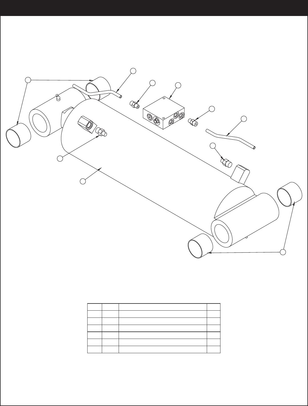
.YTQNOITPIRCSEDTRAPMETI
148384 CYLINDER 7.00X19.25 1
215822 MANIFOLD DOUBLE T11A 5000 PSI 1
3D1290 FTG ADAPT 8-6 F5OLO-S 2
40279 FTG ADAPT 6-F5OLO-S 2
519032 TUBE ASM 0.38 X 6.91 2
60635 BUSHING 40DXR32 GARLOCK 4
PN 48383
Outrigger Cylinder Assembly - PN 48383
Assembly Drawings
7
33
10
9
8
36
6
49
13
11
12
23
1
14
9
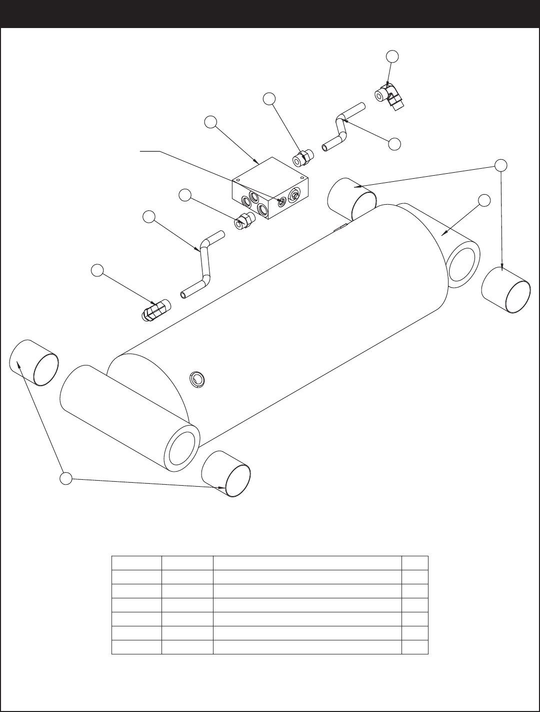
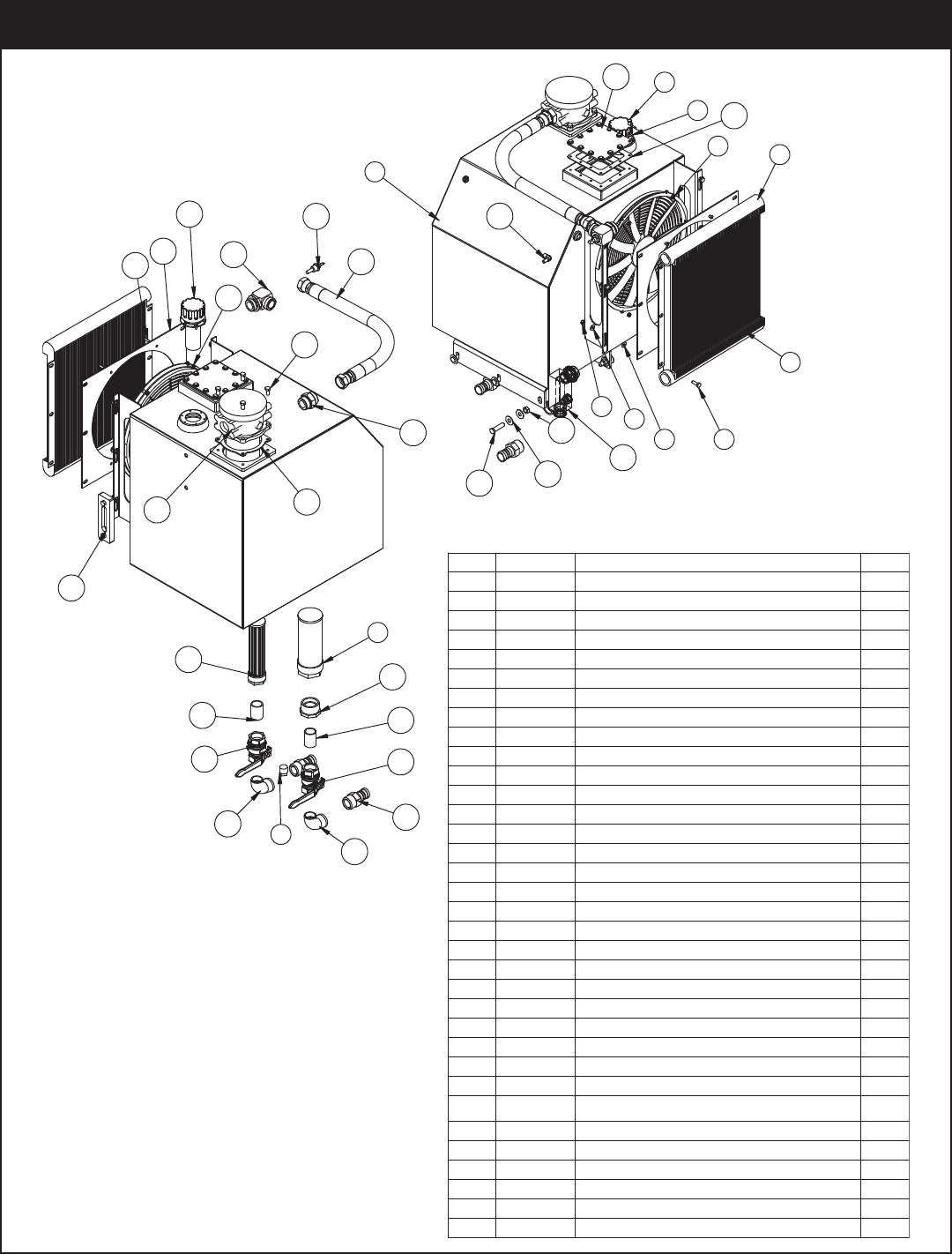
PN 41332
.YTQNOITPIRCSEDTRAPMETI
1 41333RSRVR 45GAL ORING 230001
2C2126MAGNETIC PLUG DRAIN 3/4"1
3 8241 FAN 16.00 PUSH 12 VOLT1
4C0922 CAP SCR 0.31-18X1.00 HHGR56
5C6327FILTER STRAINER 35GAL TF-20301
6 8240COOLER OIL AL 15000/230001
6COLYN HH 81-13.0 TUN24307
8 0478 CAP SCR 0.25-20X0.50 HHGR512
42TALF 52.0 REHSAW04309
10 11149 GASKET ARCTIC FOX HEATER #A-6111
11 0519 WASHER 0.44 USS FLAT ZINC12
12 0501 CAP SCR 0.50-13X2.00 HHGR56
13 C6106 NUT 0.50-13 HHGR5 NYLOC 6
14 D1263 FTG HOSE BARB 0.38 HOSE X 0.38 90DG1
1EGUAG THGIS OMREHT3645151
16 42184 FILTER TANK TOP MPF1841AG7A10HBVR1
17 19242 FTG 20-20 MFS-MORB STRAIGHT1
18 47858 HOSE 1.25(881-JC-JC-20-20-20-26)1
1PMET RVRSR 00032 GTF7587491
20 C6021 CAP SCR 0.25-20X0.75 BTNHD SS4
21 30012 SHROUD RSRVER ASM 90001
22 0333 NUT 0.25-20 HHGR5 NYLOC 4
23 47859FTG 23000 RSRVR RETURN 1
24 0492 CAP SCR 0.38-16X0.75 HHGR54
25 54393 SWITCH TEMP NC TT-F5B-100R-MP1
26 C5552 FILTER STRAINER TFS-1220-01
1KLB 52.1X00.2 GNIHSUB7094C72
28 C1057 FTG 20-20XCLOSE MP-MP NIPPLE
STRAIGHT BLK 2
252.1 LLAB EVLAV1155C92
2KLB GED 09 52.1 LE TS4964C03
31 C2282 FTG 1.25 NPT TO 1.25 BARB2
32 58284GASKET TANK TOP FILTER 1
33 11442PC PLATE COVER TANK HEATER FLANGE1
1KCEN/W MSA LLIF PAC9203643
34
19
2
5
16
17
32
18
15
21
20
22
25
24
28
29
31
30
30
29
28
26
27
Reservoir Assembly - PN 41332
28000 Owner’s Manual
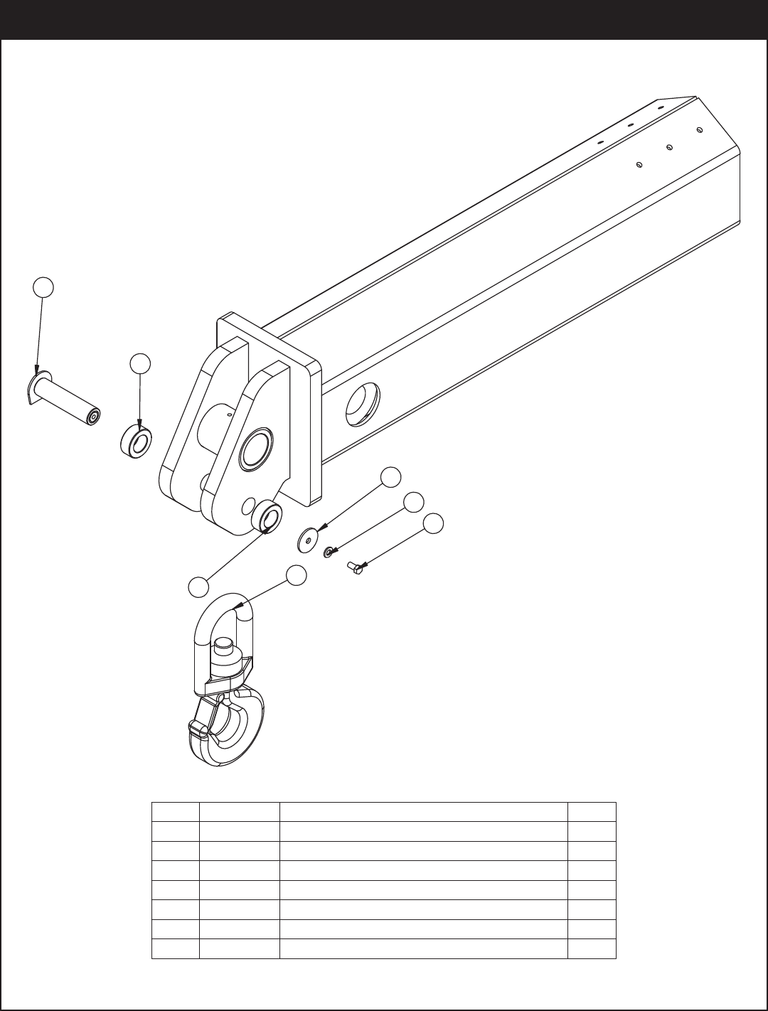
.YTQNOITPIRCSEDTRAPMETI
100082 MOOB TXE883511
2 41499 HOOK 15 TON SWIVEL CROSBY 10286541
291.1X00.3X87.1 RALLOCCP960443
191.0X05.2X65.0 PAC NIP24194
5 10172 CAP SCR 0.50-13X1.00 HHGR8 ZY1
6 16028ZP PIN TEAR DROP 1.75X7.061
18RG TALF 05.0 REHSAW0970D7
PN 55138
3
6
2
5
7
4
3
Optional 15 Ton Hook Kit - PN 55138

Hydraulics - Electrical
Chapter 8 - Hydraulics - Electrical
Never modify or alter any of the
equipment, whether mechanical,
electrical, or hydraulic, without Stellar
Industries’ approval.
Release system pressure before attempting
to make adjustments or repairs.
Do not attempt service or repair when PTO
is engaged.
Disassemble and assemble hydraulic
components on a clean surface.
Clean all metal parts in a nonflammable
cleaning fluid. Then lubricate all
components to aid in assembly.
Hydraulic fluid expands when heated. This
raises the pressure in an unventilated tank.
Release the tank pressure before removing
the cap completely. Failure to do so may
cause the oil to shoot out of the tank very
rapidly and cause severe burns.
Warning! If hydraulic fluid escapes, the
boom or crane can fall immediately.
Make sure the ground or blocking is
supporting the boom before performing
any maintenance or repair. Do not rely on
the hydraulic fluid to support the boom or
crane.
Contaminants in a hydraulic system affect
operation and will result in serious damage
to the system components. Dirty hydraulic
systems are a major cause of component
failures.
If evidence of foreign particles is found in
the hydraulic system, flush the system.
When installing metal hydraulic tubes,
tighten all bolts finger tight. Then , in order,
tighten the bolts at the rigid end, the
adjustable end, and the mounting
brackets. After tubes are mounted, install
the hoses. Connect both ends of the hose
with all bolts finger tight. Position the hose
so it does not rub the machine or another
hose and has a minimum of bending and
twisting. Tighten bolts in both couplings.
Due to manufacturing methods, there is a
natural curvature to a hydraulic hose. The
hose should be installed so any bend is
with this curvature.
WARNING!
Please read the following section before performing any work on the hydraulic/electrical
system of your crane. This section contains vital safety information and maintenance
guidlines for your crane. If questions should arise, please contact
Stellar Customer Service at 800-321-3741
28000 Owner’s Manual
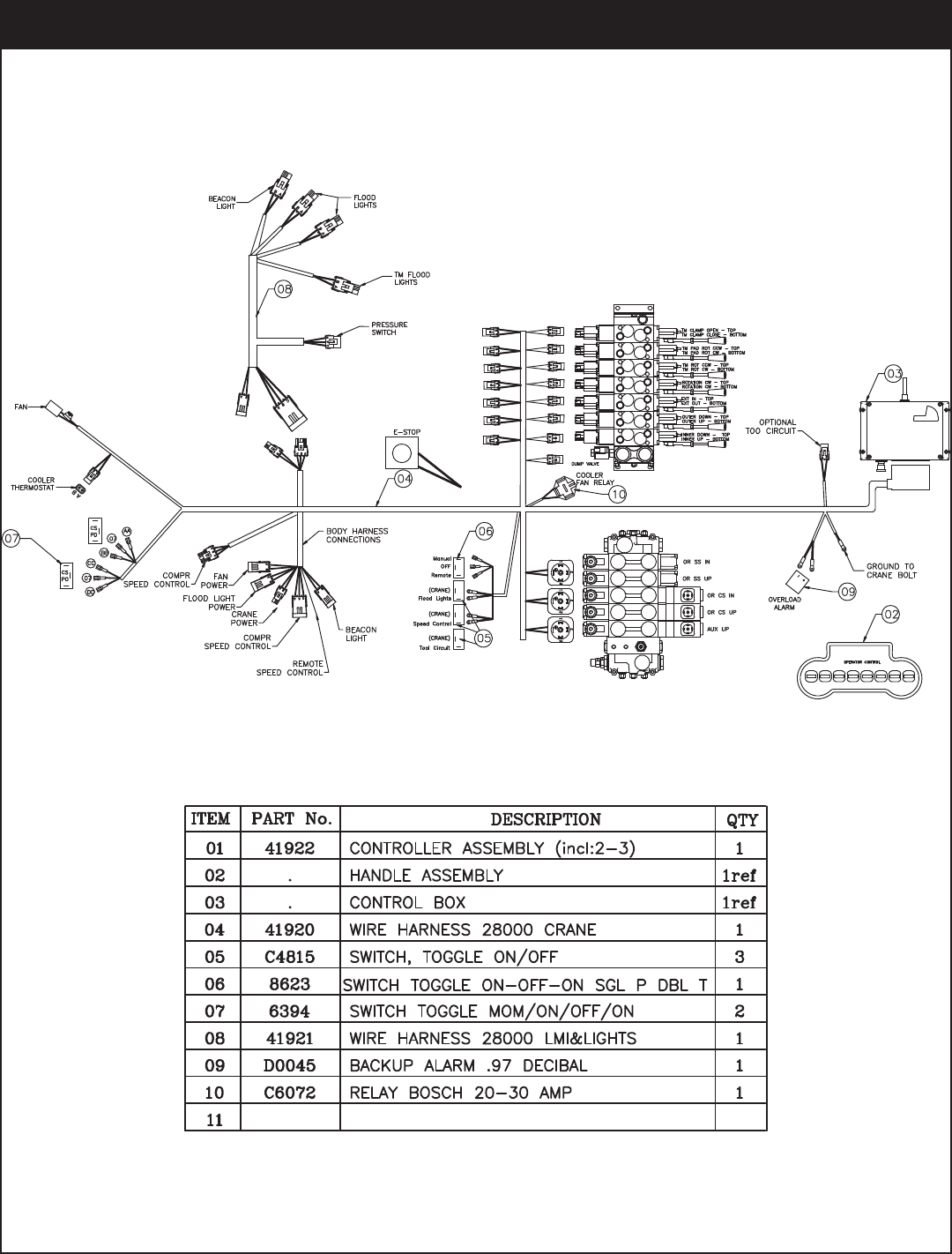
PN 41919
Control Kit - PN 41919
Hydraulics - Electrical
PN 51838
Control Kit (434 Mhz Option) - PN 51838
28000 Owner’s Manual
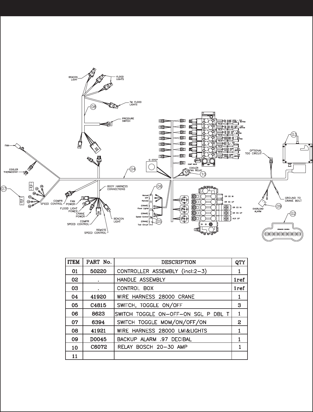
PN 55395
Control Kit (419 Mhz Option) - PN 55395
Hydraulics - Electrical
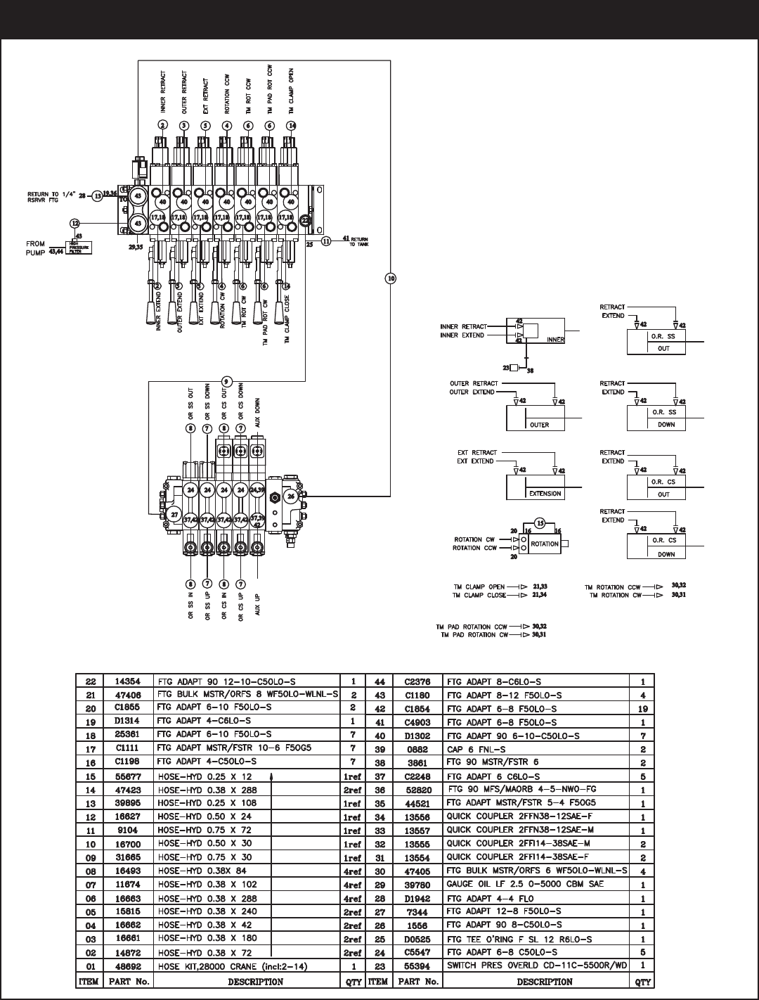
PN 48690
Hydraulic Kit - PN 48690
28000 Owner’s Manual
HYDRAULIC SYSTEM COMPONENTS
PART# DESCRIPTION
39780 Oil pressure gauge
8240 Oil cooler
22934 Hydraulic rotation motor ( Crane rotation )
22935 Valve block hydraulic motor (Crane rotation)
28485 Pressure transducer (overload)
41338 High pressure filter asm
47860 High pressure filter element (Used in p/n 41338)
18552 Fill cap assy with neck (Hydraulic reservoir)
15463 Thermo sight gauge (Hydraulic reservoir)
11149 Gasket - (Optional Artic heater cover)
C6327 Filter Strainer ( Hydraulic reservoir )
42184 Hydraulic return filter asm (Hydraulic reservoir)
47820 Hydraulic filter element (Used in p/n 42184)
47866 Control Handle - Valve bank (PVG32)
C1090 Counter balance valve ( Cylinders)
C6184 Counter balance valve (Extension & Outrigger cylinders)
15995 Manifold asm dual T2 - 5000 psi (Cylinder)
42802 Valve bank - 7 section
40827 Valve bank - 5 section
55401 Relief valve - (5 section valve bank)
50234 Dump valve - (7 section valve bank)
50235 Dump valve coil - (7 section valve bank)
47871 Valve - LMI system
13555 Hydraulic quick coupler
13554 Hydraulic quick coupler
13557 Hydraulic quick coupler
13556 Hydraulic quick coupler
C2028 O ring ( # 6 face seal ) ( hydraulic fittings )
C2029 O ring ( # 8 face seal ) ( hydraulic fittings )
32223 O ring (#10 face seal ) ( hydraulic fittings )
D1244 O ring (#12 face seal ) ( hydraulic fittings )
D1245 O ring (# 4 SAE port side ) ( hydraulic fittings )
D1246 O ring (# 6 SAE port side ) ( hydraulic fittings )
D1247 O ring (# 8 SAE port side ) ( hydraulic fittings )
D1248 O ring (#10 SAE port side ) ( hydraulic fittings )
D1249 O ring (#12 SAE port side ) ( hydraulic fittings )
D1250 O ring (#16 SAE port side ) ( hydraulic fittings )
16158 Port tube asm - ( 15604 secondary cylinder )
35647 Seal kit - Outrigger cylinder ( 9994 )
C6310 Seal kit - Outrigger cylinder ( 9993 )
35651 Seal kit - Main lift cylinder ( 15598 )
35650 Seal kit - Secondary cylinder ( 15604 )
35649 Seal kit - Extension cylinder ( 15608 )
ASSEMBLY COMPONENTS
PART# DESCRIPTION
0635 Bushing 2.50" x 2.00"
0865 Bushing 3.00" x 2.00"
2227 Bushing 3.00" x 3.00"
4381 Bushing 2.00" x 2.00"
5739 Bushing 2.50" x 3.00"
8819 Bushing 2.00" x 1.00"
13343 Bushing 2.50" x 1.00"
13817 Bushing 2.50" x 1.50"
17320 Bushing 2.50" x 2.50"
25574 Bushing 2.50" x 1.75"
8377 Pin Cap 0.56 x 3.50" x .25 SS
8597 Pin Cap 0.69 x 4.00" x .25 SS
9142 Pin Cap 0.56 x 2.50" x .25 SS
10172 Cap Screw 0.50-13 x 1.00 Gr 8
D0790 Washer 0.50 Flat Gr 8
2257 Snap ring 2.00" Internal
C5644 Grease Zerk 1/8 NPT 45 degree (Grease line kit option)
C1592 Grease Zerk 1/8 NPT (Cylinders / pivot points)
40455 Wear Pad 2.00" x 8.00" x 1.50"
15779 Wear Pad 3.00" x 5.00" x 1.75"
15778 Wear Pad 3.00" x 5.00" x 2.44"
15601 Wear Pad 1.00" x 4.00" x 12.00"
17133 Hose clamp
39959 Gear bearing rotation kit
16054 Swivel link ( 15-ton hook )
16052 Hook 15-ton Swivel
ELECTRICAL COMPONENTS
PART# DESCRIPTION
41922 Hetronic Nova radio system
47862 12v charger for Hetronic Nova radio system
47863 Battery for Hetronic Nova radio system
47867 Belt - Transmitter harness (waist)
8241 Fan 16.00 push 12 V ( Hydraulic reservoir )
6394 Toggle switch ( Outrigger operation )
8623 Toggle switch ( Outrigger operation )
C4815 Toggle switch ( Outrigger operation )
54393 Temperature switch ( Hydraulic reservoir )
22921 E-stop switch ( Crane panic bar )
61562
CONTACT SWITCH (PANIC BAR) Switch inside E-stop housing (22921)
41367 LMI system (Load Moment Indicator)
31782 Wire harness - LMI & Lights
41368 Wire harness - LMI Cinch Retro
D0045 Overload alarm
COMPRESSOR COMPONENTS (SHD245 OPTIONAL)
PART# DESCRIPTION
3853 Pilot valve 145/175 psi (SHD245 cprsr)
C4913 Solenoid valve (SHD245 cprsr)
C4914 Pressure Relief valve (SHD245 cprsr)
C0864 Hobbs air pressure switch (SHD245 cprsr)
13731 Low pressure intake valve asm (SHD245 cprsr)
13733 High pressure intake valve asm (SHD245 cprsr)
SERVICE KITS / FILTERS / LUBRICATION
PART# DESCRIPTION
4562 Air filter (SHD245 cprsr)
32893 Service Kit - 200 hour (SHD245 cprsr)
4460 Molube grease-external gear teeth for swing gears
MISCELLANEOUS COMPONENTS
PART# DESCRIPTION
51263 Flood lights ( Crane & Body )
5033 Stobe light ( Crane & Body )
14022 Compartment light
Replacement Parts
Chapter 9 - Replacement Parts
Call 800-321-3741 to Order
28000 Owner’s Manual

Troubleshooting
Chapter 10 - Troubleshooting
This chapter will list a number of
potential problems that may occur
while operating the crane. Most
problems are easily solved using the
solutions portion of this chapter. If
problems persist, please contact
Customer Service at Stellar Industries
1-800-321-3741.
Problem: Crane will not operate.
Solutions:
• Make sure that the parking brake is engaged.
• Make sure that the PTO is engaged.
• Make sure that there is 12V power going to
the radio receiver. If there is no power going
to the receiver, trace back to the power
source and check for a blown fuse or loose
ground connection.
• Make sure that the transmitter batteries are
fully charged. (Rechargeable batteries are
good for 11 months or 200 charges)
• Make sure that the hydraulic pump is
operating at its rated flow or GPMs. Check
the flow by using the flow meter to determine
the GPMs. It is possible that the hydraulic
pump is getting weak. If this is suspected,
contact Stellar Customer Service.
Problem: Crane will operate manually but
will not operate electrically.
Solutions:
• Make sure that there is 12V power going to
the radio receiver. If there is no power going
to the receiver, trace back to the power
source and check for a blown fuse or loose
ground connection.
• Make sure that the parking brake is engaged.
• Make sure that the parking brake switch is
working properly. Check the parking brake
switch by performing a continuity test. If the
switch is defective, simply replace it.
• Make sure the “Power” LED is on outside the
receiver door cover. This light is the upper
light on the receiver door. If the light does not
come on, check wiring back to the fuse. If
the fuse is OK, check system ground wires
and connections.
• Make sure the green LED on the receiver
door is lit green. This light will come on when
the red e-stop is pulled upward and the toggle
switch is activated on the transmitter. If the
radio system does not link up and no green
light is lit on the receiver - make sure that the
battery is fully charged, check the battery
contact points to make s ure they are not
tarnished or corroded. Clean contact points
and recharge or replace the battery.
• When battery voltage is acceptable, the
power LED light on the transmitter will be
solid. If the voltage becomes low, the LED
light will begin to blink and the battery will
need to be charged or replaced.
Problem: Crane operates slowly.
Solutions:
• Make sure that the crane is receiving the
recommended GPMs to operate.
• Check the level of hydraulic fluid in the
reservoir. Add fluid as needed.
• Check to see if the valve bank proportional
valve is operating.
• Make sure the proportional valve is receiving
12V power when operating a function.
If problems persist, please contact
Stellar Customer Service at:
1-800-321-3741

28000 Owner’s Manual
Problem: Cylinder drifts outward or
downward.
Solutions:
• Check to see if there is air in the hydraulic
system. Operate all cylinders connected to
the hydraulic system. Start with the extension
cylinder, then operate the main boom, winch,
rotation, and ending with the hydraulic
outriggers, if installed. When operating,
extend each cylinder halfway out, retract all
the way in, and then extend until the cylinder
rod is at the end of its stroke. Operate
cylinders slowly so air is pushed thru the
system to the reservoir. Repeat this cycle 2-3
times.
• Make sure the holding valves are operating
properly. Remove, clean, and then inspect
each holding valve. When removing a
holding valve, always relieve the pressure
inside the cylinder by loosening jam nut of the
holding valve and turning set screw
inward/clockwise. Count the number of turns
until the set screw is seated. When
reinstalling the holding valve, make sure the
valve is reset by turning the set screw the
number of turns it took to relieve the
pressure. Finish by tightening the jam nut.
• Check the cylinder rod for scratches. If a
scratch is located on the cylinder rod,
hydraulic fluid can pass thru and cause a loss
of pressure. Replace cylinder rod or cylinder.
• Check to see if the piston seals are damaged.
If they show signs of damage, install a new
cylinder seal kit.
Problem: Not all crane functions operate
using the radio remote transmitter or crane
operates intermittently.
Solutions:
• Make sure that the function switch is working
properly. If the switch is defective, simply
replace it.
• Make sure that there is power going from the
valve bank twin solenoid or to the function
that will not operate. If no power is going to
the twin solenoid, check wiring connections
on wire harness plug connector for broken
wires, loose connection or poor crimp. If
power is going to the solenoid valve, it may
not be opening to allow hydraulic oil to the
function that is not operating. Check the twin
solenoid for polarity, if solenoid does not
magnetize, replace the twin solenoid.
Problem: Outer “Extend” and Extension In and
Out will not operate Manually or Remotely.
Solutions:
• Check to see if the functional cut out connector,
located on the valve section is lit. Note:
Functional cut out connectors will have an LED
light on when electrical power is present
• Check to see if there is 12 volt power going to
functional cut out connector.
• Check to make sure the Bosch relay is
functioning properly. It is located just behind
the panic bar E-stop switch. If functional cut out
connector is lighting properly, check to make
sure the connector is tight.

Troubleshooting
Vibrations and jerking in hydraulic cylin-
der during the first maneuvers.
The temperature of the hydraulic oil is
too low.
lack of oil in reservoir.
Perform maneuvers without loads for
several minutes to warm up the oil.
Add hydraulic oil.
Vibrations with every function when oil
is hot.
Lack of oil in reservoir.
air in hydraulic system.
Add hydraulic oil to the tank.
Operate the control carrying the cylin-
ders to stroke end several times in both
directions.
All crane movements are slow, loaded
and unloaded.
Suction hose from oil tank crushed or
obstructed.
Dump valve malfunctioning.
The pump is drawing in air.
Replace or clean the suction hose.
Manually override system to detect
Tighten suction hose connections.
The hydraulic extension is not extend-
ing.
Bad lubrication.
Wear pads are worn.
Sequence valve on extension cylinder
has to be adjusted.
Lubricate the wear pads
Replace wear pads.
Check to see if there is 12V power
going to the extension function.
Crane rotation not regular Inadequate grease.
The truck is not level.
Worn rotation motor.
Gear bearings worn.
Grease gear bearing.
Level the truck.
Replace rotation motor.
Replace gear.
The crane does not lift the loads on the
load chart.
Defective hydraulic pump.
Incorrect settings of the valves.
Hydraulic cylinder seals are worn.
Replace the pump.
Adjust valve settings.
Replace worn seals.
The crane lifts the load, but cannot hold
it.
Incorrect relief setting.
Faulty holding valve.
Incorrect settings of the valves.
Hydraulic cylinder seals are worn.
Contact Stellar customer service for
proper setting.
Replace holding valve.
Adjust valve settings.
Replace worn seals.
Noise coming from Articulation points. Lack of lubrication.
Worn pin.
Worn bushing.
Grease articulation points.
Replace pin.
Replace bushing.
Troubleshooting continued...
Problem Possible Cause Possible Solution

28000 Owner’s Manual
Hydraulic legs do not hold under load. Defective holding valves
Worn seals in the stabilizer cylinder.
Clean or replace holding valves.
Replace worn seals.
Crane does not function. Truck battery discharged
Electric connections are damaged or
corroded.
Control handle turned off.
Charge battery.
Check electrical wiring, terminals, con-
nections and their integrity.
Turn on control handle
Crane does not function - Continued Battery charge low.
Burned fuses
Dump valve not operating properly.
PTO not fully engaged.
Charge transmitter battery.
Replace the fuses.
Bypass electrical circuit
Check for full engagement.
Control box lights do not operate
(green LED out)
Discharged battery.
Burned fuses.
Disconnected electrical cord.
Corroded or loose electrical connec-
tions.
Faulty manual/remote switch.
Recharge battery.
Replace fuses.
Join correctly the connection, replace
the electric coupling.
Check electrical connections.
Replace switch.
A crane function does not work. Defective switch.
Faulty solenoid.
Locked valve cartridge.
Damaged electric connection.
Replace the switch.
Replace the solenoid.
Disassemble and clean the valve car-
tridge.
Check continuity of the circuit.
Operations at high or low speed do not
work.
Parameters of control box (receiver)
set incorrectly or have failed.
Contact Stellar customer service
department.
Controls fail to respond with control
box.
Batteries dead in wireless handle.
Handle on/off button isn’t turned on.
Manual/remote switch is in manual
position.
Recharge or replace batteries in
remote handle.
Turn on on/off button on remote han-
dle.
Position manual/remote switch in
remote position.
Operation slow down. Hydraulic oil supply is low.
Hydraulic pump is operating at a
reduced speed.
Relief valve is set too low.
Pump or cylinder is worn.
Add hydraulic oil.
Engine idle speed may be too slow,
increase speed.
Check relief with gauge.
Replace cylinder seals.
Problem Possible Cause Possible Solution

Troubleshooting
Operation slow down - con’t Pump is slipping due to excessive oil
temperature, this is a factor which will
increase with worn components.
Filters are dirty.
Obstruction has occurred in boom hold-
ing valve.
Check pump GPM with flow meter if it
is suspected to be faulty.
Replace filters.
Replace or clean holding valve.
Operation slow down - con’t Defective flow valve. Replace valve.
Boom drifts when loaded and controls
neutralized.
Hydraulic oil is bypassing at piston
seal.
Main or secondary cylinder holding
valves are defective or contaminated.
Replace cylinder.
Clean or replace holding valves.
Unusual noise in operation. Cavitation is occurring due to low
hydraulic oil supply.
Restriction or collapse of suction line
has occurred.
Suction line screen is clogged and
requires replacement.
Add oil and cycle cylinders to get air
out of system.
Inspect suction line for damage.
Replace or clean screen.
Unusual noise in operation - con’t Bypass settings on relief valve are too
low.
Relief valve is damaged.
Contact customer service for correct
relief setting.
Replace relief valve.
Outriggers fail to retract Control valve is inoperative.
Cylinder seals or holding valve are
defective
Hydraulic lines are restricted or rup-
tured.
If outriggers retract using manual func-
tion, it is a probable electrical problem -
check continuity.
Replace seals or holding valve.
Inspect and replace hydraulic lines.
Outriggers fail to retract-con’t Broken electrical wire going to outrig-
ger switch to the valve bank.
Check continuity of circuit.
Outriggers yield or drift. Control valve is inoperative.
Cylinder or check valve is defective.
Hydraulic lines are restricted or rup-
tured.
Clean or replace pulsar solenoid valve.
Replace holding valve.
Check hoses for damage and replace.
Problem Possible Cause Possible Solution

28000 Owner’s Manual
BMS-2 Receiver Troubleshooting
Available on some systems. Consult BMS-2 Operator Manual for details.
Problem Probable Cause Correction
System will not initialize after
normal start-up procedure.
E-Stop reset
Joystick or paddle lever not in
center position.
E-Stop switch engaged.
Battery fully discharged.
No power to the receiver.
Push the Start button again. If the system is being initialized from an E-Stop
condition, the Start button must be pressed twice - first to clear the E-Stop, then
again, to start the system.
Be sure that all joysticks and paddle levers are in center position when the Start
button is activated.
Pull out E-Stop switch. Restart system by pressing Start twice.
Check battery to ensure a full charge. Replace with fully charged battery if
necessary.
Check the diagnostic Display on the side of the receiver to be sure power is
applied. Ensure that the system is securely grounded to the negative battery
terminal. The Display also indicates normal transmitter communication,
interference, and E-Stop conditions.
The transmitter is turned on,
but does not transmit (Power
LED not flashing)
Battery is discharged.
Coder board fuse.
Broken key switch.
Coder board failure.
Replace battery with a fully charged battery.
Check fuse and replace if necessary.
Check wiring on key switch. Replace key switch, wiring or contact element.
Contact Hetronic or your Dealer.
Transmitter is transmitting
(Power LED flashing), but
crane will not respond.
E-Stop switch engaged.
Transmitter out of range.
Joystick, paddle lever or switch
not in center position when
transmitter turned on.
Receiver power off.
Blown fuse in receiver.
E-Stop failure in transmitter.
E-Stop failure in receiver. Red E-
Stop LED on decoder board is
illuminated.
E-Stop module failure.
Pull out the E-Stop pushbutton and press the Start/Horn pushbutton.
Take the transmitter back into the range of the receiver. Press the Start/Horn
pushbutton.
Ensure that all control devices are in center (neutral) position when the Start button
is activated.
Turn on power to receiver.
Check all fuses. Replace if necessary.
Check E-Stop pushbutton for damage. Check wiring to contact element for broken
or disconnected wires. Repair or replace E-stop pushbutton or wiring.
Check wiring on E-Stop module, decoder module, E-Stop decoder module. Secure
any loose connections.
Replace E-Stop module.
All crane/machine
motions operate
intermittently
Receiver antenna loose or
missing.
External antenna (if used) has
loose connection, poor grounding
or interference.
Connector wiring too close to
power wiring.
Connector inside receiver is
loose.
Tighten or replace antenna.
Tighten antenna and ground connection. See "Connecting an External Antenna"
Section for operational precautions.
Control wiring must be run separately from power wiring.
Check all connectors, reseat if necessary.
Some crane/machine
motions operate
intermittently
Crane/machine motion wiring may
be loose.
Connector inside receiver is
loose.
Connector wiring too close to
power wiring.
Check wiring from receiver to plug and from plug to crane/machine motion
actuator.
Check all connectors, reseat if necessary.
Control wiring must be run separately from power wiring.

Limited Warranty Statement
Stellar Industries, Inc. (Stellar) warrants products designed and manufactured by Stellar to be free from defects in material and workmanship under
proper use and maintenance. Products must be installed and operated in accordance with Stellar’s written instructions and capacities. This warranty
shall cover the following:
Stellar Cranes, Stellar Hooklift Hoists, Stellar Cable Hoists, Stellar Container Carriers, Stellar Service Trucks, and Stellar X-Tra-Lift Systems:
Twelve (12) month warranty on parts from the date recorded by Stellar as the in-service date, not to extend beyond twenty-four (24) months from date
ofmanufacture,
Twelve (12) month repair labor from the date recorded by Stellar as the in-service date, not to extend beyond twenty-four (24) month from date of
manufacture, and
Thirty-six (36) month warranty on all Stellar Manufactured structural parts from the date recorded by Stellar as the in-service date, not to extend beyond
forty-eight (48) months from date of manufacture.
Stellar Tarper Systems:
Twelve (12) month warranty on parts from the date recorded by Stellar as the in-service date, not to extend beyond twenty-four (24) months from date
of manufacture and
Three (3) month repair labor from the date recorded by Stellar as the in-service date, not to extend beyond fifteen (15) month from date of
manufacture.
The in-service date will be derived from the completed warranty registration card. In the event a warranty registration card is not received by Stellar, the
factory ship date will be used.
Stellar’s obligation under this warranty is limited to, and the sole remedy for any such defect shall be, the repair and/or replacement (at Stellar’s option)
of the unaltered part and/or component in question. Stellar after-sales service personnel must be notified by telephone, fax, or letter of any warranty-
applicable damage within fourteen (14) days of its occurrence. If at all possible, Stellar will ship the replacement part within 24-hours of notification by
the most economical, yet expedient, means possible. Expedited freight delivery will be at the expense of the owner.
Warranty claims must be submitted and shall be processed in accordance with Stellar’s established warranty claim procedure. Stellar after-sales service
personnel must be contacted prior to any warranty claim. A return materials authorization (RMA) account number must be issued to the claiming party
prior to the return of any warranty parts. Parts returned without prior authorization will not be recognized for warranty consideration. All damaged parts
must be returned to Stellar freight prepaid; freight collect returns will be refused. Freight reimbursement of returned parts will be considered as part of
the warranty claim.
Warranty service will be performed by any Stellar new equipment distributor, or by any Stellar-recognized service center authorized to service the type
of product involved, or by the Stellar factory in the event of a direct sale. At the time of requesting warranty service, the owner must present evidence
of date of delivery of the product. The owner shall be obligated to pay for any overtime labor requested of the servicing company by the owner, any
field service call charges, and any towing and/or transportation charges associated with moving the equipment to the designated repair/service
provider.
All obligations of Stellar and its authorized dealers and service providers shall be voided if someone other than an authorized Stellar dealer provides
other than routine maintenance service without prior written approval from Stellar. In the case repair work is performed on a Stellar-manufactured
product, original Stellar parts must be used to keep the warranty in force. The warranty may also be voided if the product is modified or altered in any
way not approved, in writing, by Stellar.
The owner/operator is responsible for furnishing proof of the date of original purchase of the Stellar product in question. Warranty registration is the
ultimate responsibility of the owner and may be accomplished by the completion and return of the Stellar product registration card provided with the
product. If the owner is not sure of registration, he is encouraged to contact Stellar at the address below to confirm registration of the product in
question. This warranty covers only defective material and workmanship. It does not cover depreciation or damage caused by normal wear and tear,
accident, mishap, untrained operators, or improper or unintended use. The owner has the obligation of performing routine care and maintenance
duties as stated in Stellar’s written instructions, recommendations, and specifications. Any damage resulting from owner/operator failure to perform such
duties shall void the coverage of this warranty. The owner will pay the cost of labor and supplies associated with routine maintenance.
The only remedies the owner has in connection with the breach or performance of any warranty on the Stellar product specified are those set above.
In no event will Stellar, the Stellar distributor/dealer, or any company affiliated with Stellar be liable for business interruptions, costs of delay, or for any
special, indirect, incidental, or consequential costs or damages. Such costs may include, but are not limited to, loss of time, loss of revenue, loss of use,
wages, salaries, commissions, lodging, meals, towing, hydraulic fluid, or any other incidental cost.
All products purchased by Stellar from outside vendors shall be covered by the warranty offered by that respective manufacturer only. Stellar does not
participate in, or obligate itself to, any such warranty.
Stellar reserves the right to make changes in design or improvement upon its products without imposing upon itself the same upon its products
theretofore manufactured.
This warranty will apply to all Stellar Cranes, Stellar Hooklift Hoists, Stellar Cable Hoists, Stellar Container Carriers, Stellar Service Trucks, Stellar X-Tra-Lift
Systems, and Stellar Tarper Systems shipped from Stellar’s factory after January 1st, 2010. The warranty is for the use of the original owner only and is not
transferable without prior written permission from Stellar.
THIS WARRANTY IS EXPRESSLY IN LIEU OF ANY OTHER WARRANTIES, EXPRESS OR IMPLIED, INCLUDING ANY WARRANTY OF MERCHANTABILITY OR FITNESS FOR
A PARTICULAR PURPOSE. REMEDIES UNDER THIS WARRANTY ARE LIMITED TO THE PROVISION OF MATERIAL AND SERVICES, AS SPECIFIED HEREIN. STELLAR
INDUSTRIES, INC. IS NOT RESPONSIBLE FOR INCIDENTAL OR CONSEQUENTIAL DAMAGES.
Revision Date: February 2010 Document Number: 37040
