Stellar Industries 5521 Users Manual Telescopic Crane
2015-02-02
: Stellar-Industries Stellar-Industries-5521-Users-Manual-488634 stellar-industries-5521-users-manual-488634 stellar-industries pdf
Open the PDF directly: View PDF ![]() .
.
Page Count: 42
- Chapter 1 - Specifications
- Chapter 2 - Installation
- Installation Overview
- Control Kit (Flip Sheave/CDT Boost) - PN 57913
- Control Kit (Flip Sheave/CDT Non-Boost) - PN 59154
- Control Kit (Flip Sheave/12V/CDT Boost) - PN 58276
- Control Kit (Flip Sheave/12V/CDT Non-Boost) - PN 59522
- Control Kit (Cradle A2B/CDT Boost) - PN 59138
- Control Kit (Cradle A2B/CDT Non-Boost) - PN 59155
- Control Kit (Cradle A2B/12V/CDT Boost) - PN 59523
- Control Kit (Cradle A2B/12V/CDT Non-Boost) - PN 59524
- Hydraulic Kit - PN 58277
- Hydraulic Kit (12 Volt Version) - PN 58279
- Valve Bank - PN 44530
- Hydraulic Installation
- Hydraulic Syste
- Decal Kit Placement - PN 57304
- Chapter 3 - Assembly Drawings
- Base Assembly - PN 50364
- Mast Assembly - PN 57577
- Main Boom Assembly - PN 57581
- Extension Boom Assembly (Flip Sheave) - PN 57593
- Extension Boom Assembly (Cradle A2B) - PN 58290
- Extension Boom Assembly (Flip Sheave - 1 Hyd/1 Manual) - PN 57935
- Extension Boom Assembly (Cradle A2B - 1 Hyd/1 Manual) - PN 59146
- Main Cylinder Assembly - PN 54942
- Extension Cylinder Assembly - PN 49316
- Extension Cylinder Assembly (1 Hyd/1 Manual) - PN 57936
- Cable & Hook Assembly - PN 57597
- Power Unit Assembly - PN 57939
- CDT™ Radio Transmitter Assembly - PN 56647
- Chapter 4 - Replacement Parts
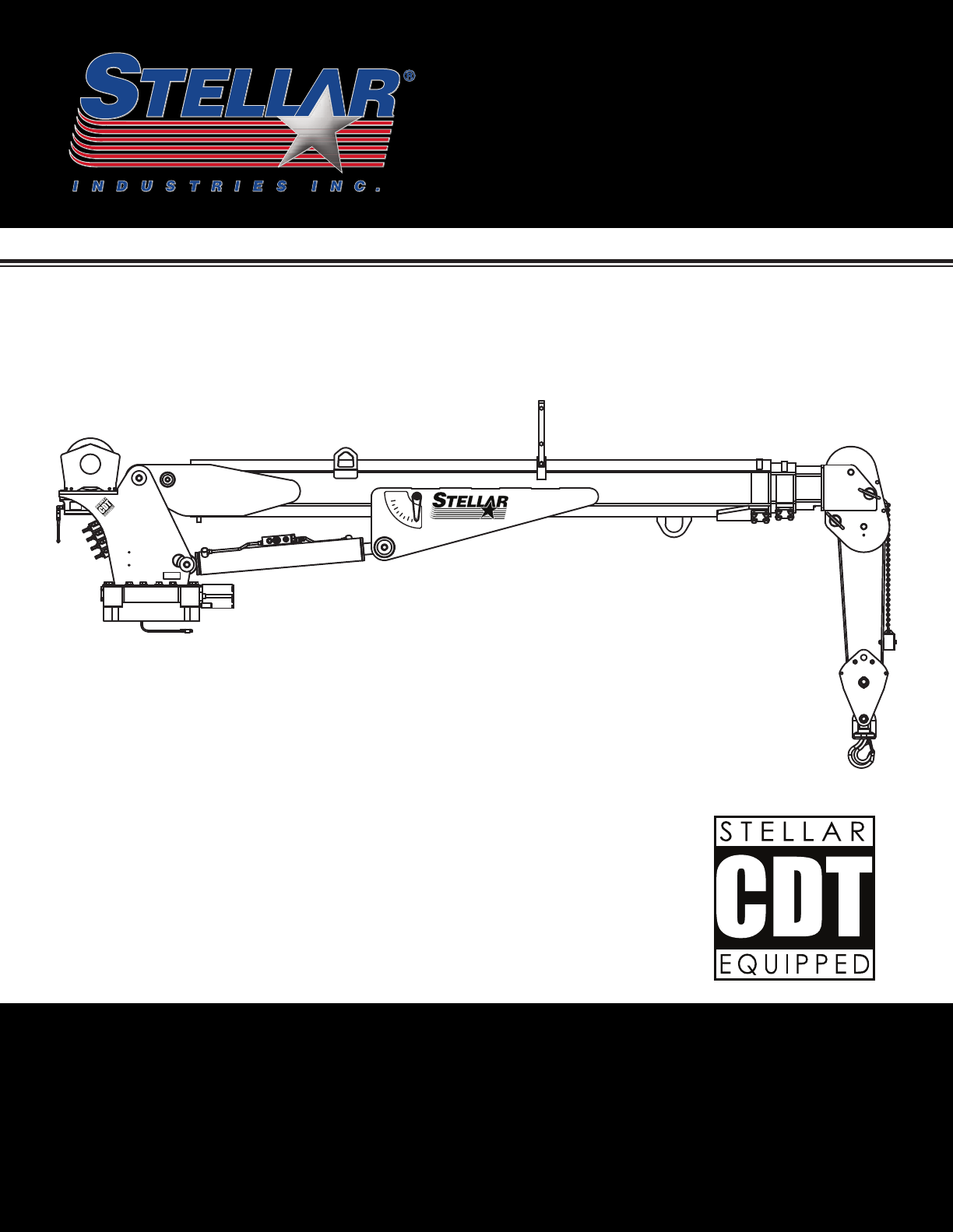
®®
5521
60
50
0
20
30
10
40
Angle Indicator
80
70
!$%%"!($$ '#&!$(#%$
)
Stellar Industries, Inc.
190 State Street
PO Box 169
Garner, IA 50438
800-321-3741
Fax: 641-923-2811
www.stellarindustries.com Last Revision: 09/06/12
Subject to Change without Notification.
© 2012 Stellar Industries, Inc.
®
TM

5521 Manual Revisions
Date of Revision Description of Revision
Section Revised

Find a Dealer Near You:
http://www.stellarindustries.com/pages/dist/distsearch.htm
For Technical Questions, Information, Parts, or Warranty, Call Toll-Free at
800-321-3741
Hours: Monday - Friday, 8:00 a.m. - 5:00 p.m. CST
Or email at the following addresses:
Technical Questions, and Information service@stellarindustries.com
Order Parts parts@stellarindustries.com
Warranty Information warranty@stellarindustries.com
Table of Contents
Chapter 1 - Specifications 1
Model Stellar® 5521 Crane Specifications Sheet 1
Stellar® 5521 Geometric Measurements 2
Capacity Chart - Decal PN 57598 3
Chapter 2 - Installation 5
Installation Overview 6
Control Kit (Flip Sheave/CDT Boost) - PN 57913 7
Control Kit (Flip Sheave/CDT Non-Boost) - PN 59154 8
Control Kit (Flip Sheave/12V/CDT Boost) - PN 58276 9
Control Kit (Flip Sheave/12V/CDT Non-Boost) - PN 59522 10
Control Kit (Cradle A2B/CDT Boost) - PN 59138 11
Control Kit (Cradle A2B/CDT Non-Boost) - PN 59155 12
Control Kit (Cradle A2B/12V/CDT Boost) - PN 59523 13
Control Kit (Cradle A2B/12V/CDT Non-Boost) - PN 59524 14
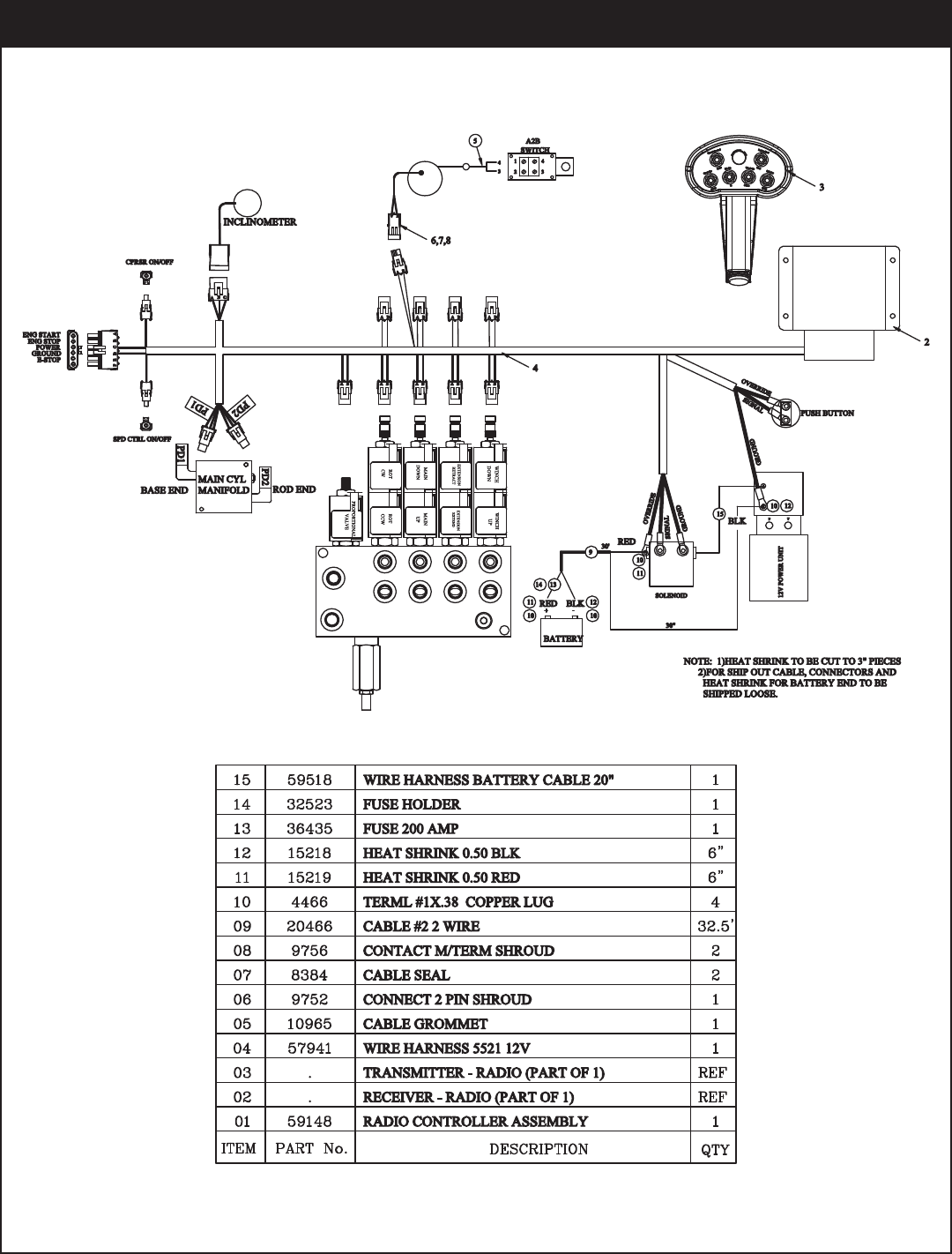
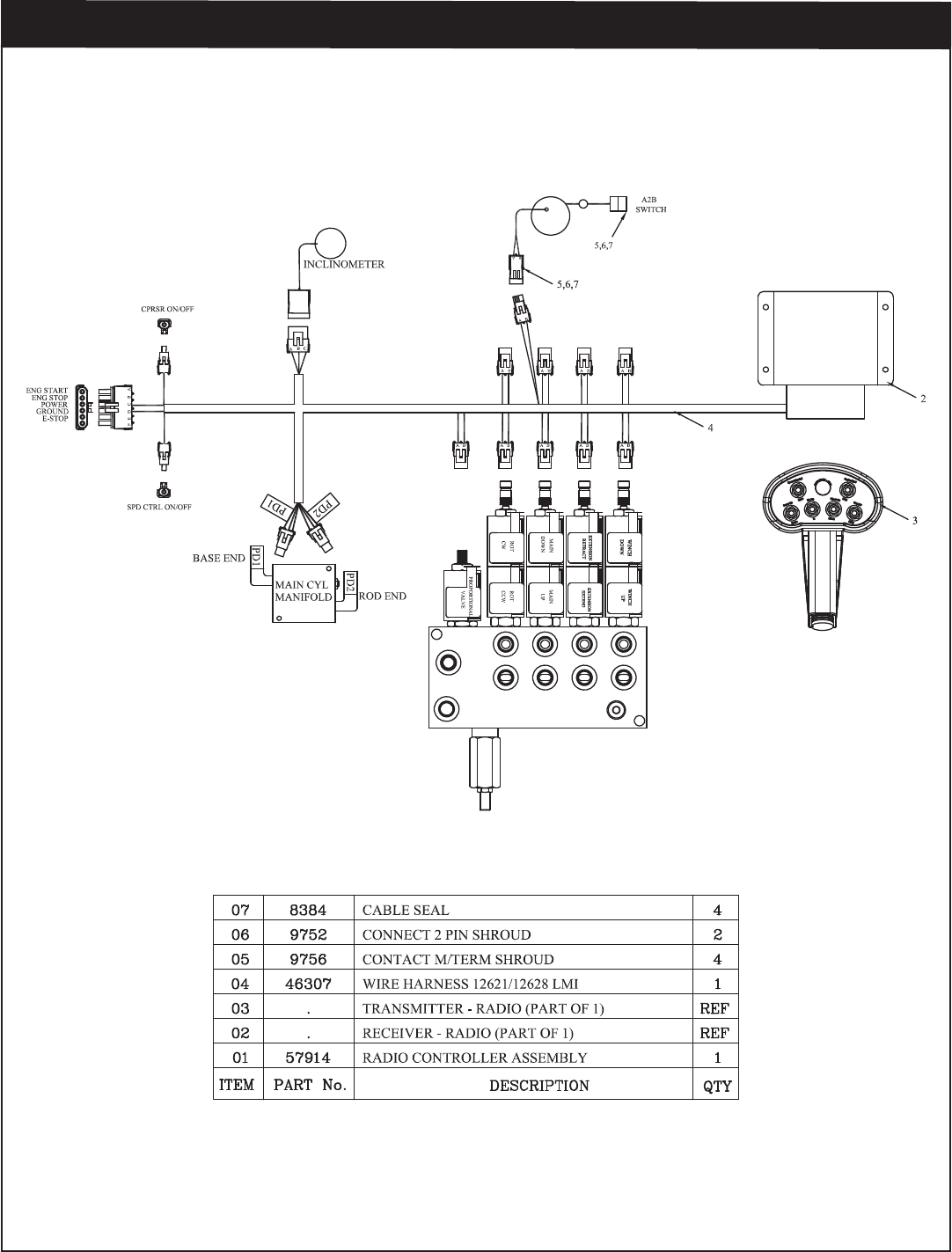
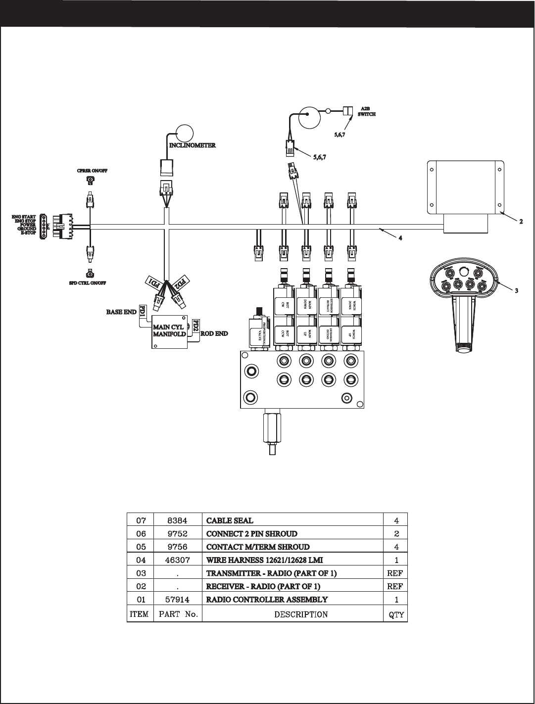
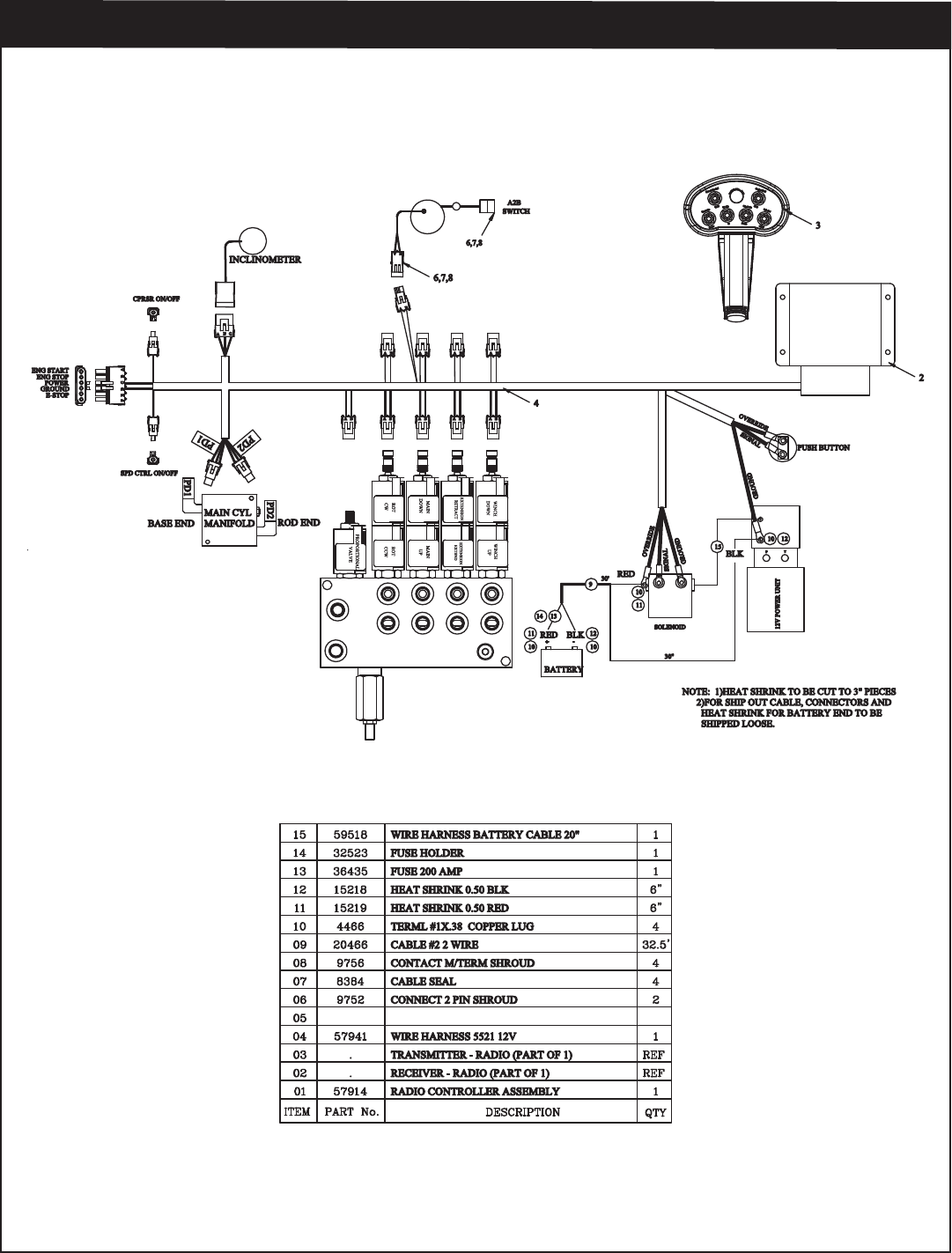
Wiring Diagram (Electrical Version) 15
Hydraulic Kit - PN 58277 16
Hydraulic Kit (12 Volt Version) - PN 58279 17
Valve Bank - PN 44530 18
Hydraulic Installation 19
Hydraulic System 20
Stability Procedure 21
Decal Kit Placement - PN 57304 22
Chapter 3 - Assembly Drawings 23
Base Assembly - PN 50364 23
Mast Assembly - PN 57577 24
Main Boom Assembly - PN 57581 25
Extension Boom Assembly (Flip Sheave) - PN 57593 26
Extension Boom Assembly (Cradle A2B) - PN 58290 27
Extension Boom Assembly (Flip Sheave - 1 Hyd/1 Manual) - PN 57935 28
Extension Boom Assembly (Cradle A2B - 1 Hyd/1 Manual) - PN 59146 29
Main Cylinder Assembly - PN 54942 30
Extension Cylinder Assembly - PN 49316 31
Extension Cylinder Assembly (1 Hyd/1 Manual) - PN 57936 32
Cable & Hook Assembly - PN 57597 33
Power Unit Assembly - PN 57939 34
CDT™ Radio Transmitter Assembly - PN 56647 35
Chapter 4 - Replacement Parts 37
Table of Contents
5521 Owner’s Manual
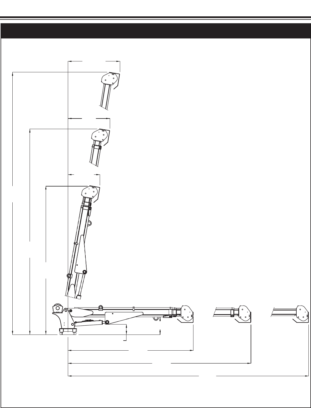
4'7"
(1.40m)
3'9"
(1.14m)
2'10"
(0.87m)
22'10"
(6.95m)
17'10"
(5.45m)
12'11"
(3.93m)
10.69”
(0.27m)
18.41”
(0.47m)
11’0”
(3.34m)
16’0”
(4.87m)
21’0”
(6.39m)
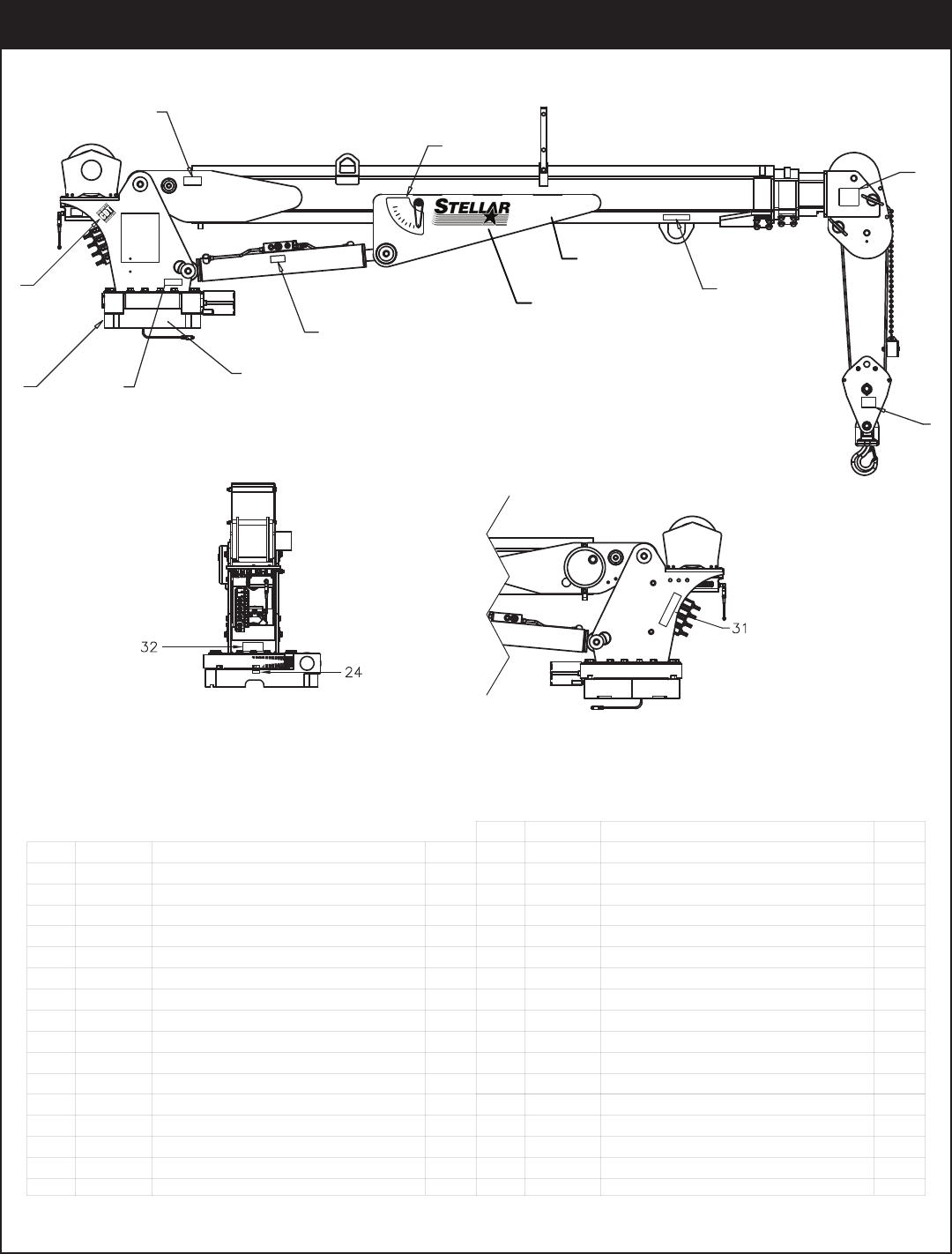
Specifications
Chapter 1 - Specifications
Crane Rating: 29,500 ft-lb (4.1 ton-m)*
Standard Boom Length: 11’ 0” (3.35 m) from CL of Crane
Boom Extension: 1st stage: Hydraulic 60” (152.4 cm)
2nd stage: Manual 60” (152.4 cm)
Optional: 2nd stage: Hydraulic 60” (152.4 cm)
Maximum Horizontal Reach: 21’ 0” (6.39 m) from CL of Crane
Maximum Vertical Lift: 22’ 10” (6.95 m)
(from crane base)
Boom Elevation: -5 to +80 degrees
Stowed Height: 32” (81.3 cm)
(crane only)
Mounting Space Required: 20” x 21” (50.8 x 53.3 cm)
Approximate Crane Weight: 1400 lbs (635 kg)
Controls: Radio control standard for all
functions.
Winch Specifications
Rope Diameter: 5/16" (8 mm)
Line pull speed: 70 ft/min (21.34 m/min)
20 ft/min (6.09 m/min) - Electric Version
Max. single part line: 2500 lbs (1130 kg)
Max. double part line: 5000 lbs (2265 kg)
Rotation: 400 degree power
(worm gear)
Lifting Capacities: 5000 lbs @ 5’10” (2265 kg @ 1.78 m)**
1400 lbs @ 21’ (635 kg @ 6.40 m)**
Power Supply Required: PTO & Pump
(8.0 gpm @ 2500 psi)
(30.31 lpm @ 173 bar)
12 volt power unit
(2.0 gpm @ 2500 psi)
(7.57 lpm @ 172 bar)
*Crane rating in Boost Mode. Normal crane rating is 25,000 ft-lbs (3.46 ton-m)
**Maximum capacities in Boost Mode.
Model Stellar® 5521 Crane Specifications Sheet
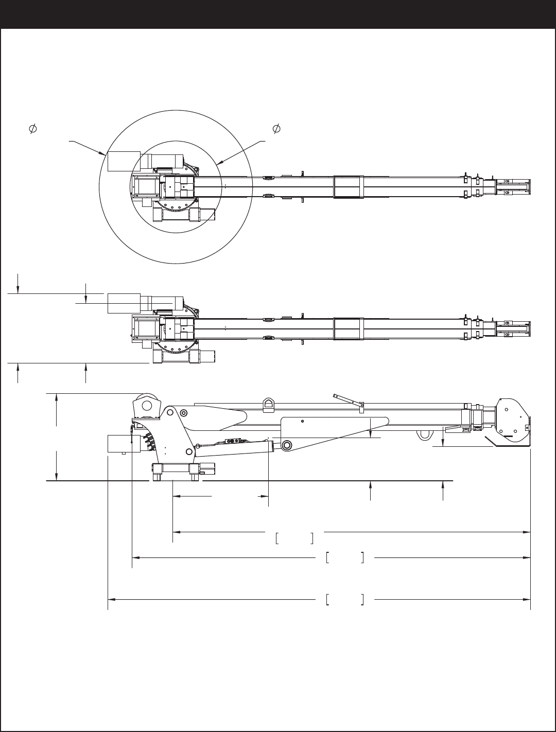
Stellar® 5521 Geometric Measurements
33.80
[0.86m]
HYD
56.47
[1.43m]
12V
35.13
[0.89m]
15.75
[0.40m]
CG
32.15
[0.82m]
12'3"
11'0"
3.34m
[0.32m]
12.61
3.72m
HYD
12'11"
12V
3.95m
[0.65m]
12V
25.70 22.11
[0.56m]
HYD
5521 Owner’s Manual
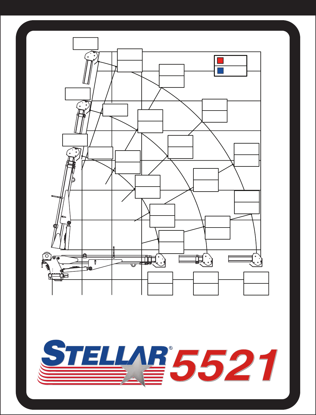
Reach in Feet/Meters
Capacity in Pounds/Kilograms
Weight of load handling devices are
part of the load lifted and must be
deducted from the capacity.
PN 57598
Maximum 1 - part line capacity is
2500 lbs (1130 kg). For greater
loads, use 2 - part line.
4080 kgs
4080 kgs
4080 kgs
4080 kgs
4080 kgs
80º
45º
75º
60º
15º
30º
9000#
9000#
9000#
9000#
9000#
4755 lbs
2155 kg
5000 lbs
2265 kg
5000 lbs
2265 kg
5000 lbs
2265 kg
5000 lbs
1870 kg
5000 lbs
2265 kg
4030 lbs
1825 kg 2665 lbs
1205 kg
2260 lbs
1025 kg
3445 lbs
1560 kg
2920 lbs
1320 kg
4865 lbs
2205 kg
4125 lbs
2840 kg
3650 lbs
1655 kg
3095 lbs
1400 kg
3090 lbs
1400 kg
2620 lbs
1185 kg
2120 lbs
960 kg
1800 lbs
815 kg
1620 lbs
730 kg
1375 lbs
620 kg
1945 lbs
880 kg
1650 lbs
745 kg
2680 lbs
1215 kg
2275 lbs
1030 kg
1840 lbs
830 kg
1560 lbs
705 kg
1400 lbs
635 kg
1190 lbs
535 kg
1475 lbs
665 kg
1250 lbs
565 kg
2535 lbs
1150 kg
2150 lbs
975 kg
1945 lbs
880 kg
1650 lbs
745 kg
0'
0 m
3'
.914 m
6'
1.83 m
9'
2.74 m
11'
3.35 m
21'
6.40 m
16'
4.88 m
12'
3.66 m
3'
.914 m
6'
1.83 m
9'
2.75 m
15'
4.57 m
18'
5.49 m
21'
6.40 m
23'
7.01 m
Boost
(If Equipped)
Standard
2905 lbs
1315 kg
2465 lbs
1115 kg
Capacity Chart - Decal PN 57598
Specifications
5521 Owner’s Manual

Installation
Chapter 2 - Installation
General Installation
This chapter is designed to serve as a
general guide for the installation of a Stellar
5521 Telescopic Crane on a Stellar Service
Body. Each installation is considered unique
so certain portions of this chapter may or
may not apply to your direct application. If
a question should arise during the installation
process, please contact Stellar Customer
Service at (800) 321 3741.
This crane is designed for use with a Stellar
Service Body installed on a vehicle that
meets the minimum chassis requirements of
the crane. It is the installer’s responsibility to
assure that the crane is mounted on a
platform that will support the maximum
crane rating of this crane.
Notice:
PTO and Pump installation instructions are
provided by the corresponding
manufacturers. For more information on
which PTO and Pump fit your application,
please contact your local Stellar Distributor
or Stellar Customer Service.
Installation Notice
According to Federal Law (49 cfr part 571),
each final-stage manufacturer shall
complete the vehicle in such a manner that
it conforms to the standards in effect on the
date of manufacture of the incomplete
vehicle, the date of final completion, or a
date between those two dates. This
requirement shall, however, be superseded
by any conflicting provisions of a standard
that applies by its terms to vehicles
manufactured in two or more stages.
Therefore, the installer of Stellar cranes and
bodies is considered one of the
manufacturers of the vehicle. As such a
manufacturer, the installer is responsible for
compliance with all applicable federal and
state regulations. They are required to
certify that the vehicle is in compliance with
the Federal Motor Vehicle Safety Standards
and other regulations issued under the
National Traffic and Motor Vehicle Safety
Act.
Please reference the Code of Federal
Regulations, title 49 - Transportation, Volume
5 (400-999), for further information, or visit
http://www.gpoaccess.gov/nara/index.html
for the full text of Code of Federal
Regulations.
Notice: Read this Page Before Installation of the Crane
Important: When installing welder units to the service
bodies, it is highly recommended that a surge
protector is installed on the chassis batteries to protect
the crane radio receiver, wiring and other electronic
devices from an unexpected electrical spike or surge.
Failure to do so could result in extensive damage to
the service body and crane electrical circuit.
1
2
.YTQNOITPIRCSEDTRAPMETI
1 5199 CAP SCR 1.00X8X3.00 HHGR8 ZY4
2 6538 WASHER 1.00 SAE FLAT YELLOW GR84
Motor
Hole Mounting Detail
Ø1.063
7.38
14.75
7.38
14.75
Ø6.00
4 Places
WARNING!
The use of this crane on a
body not capable of handling
the loads imposed on it may
result in serious injury or
death.
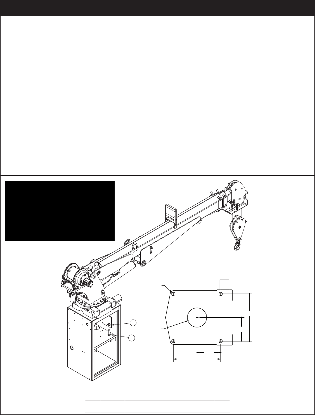
Installation Overview
1. Determine that the mounting location for the 5521 crane is at least 18” x 20” (45.7 x 50.8 cm).
2. Use the detail below to drill 1.06” diameter holes into the mounting plate. Run tap on the threads of the
base to be sure they are clean.
3. Use a crane or lifting device capable of lifting the weight of the Stellar crane. The Stellar 5521weighs
approximately 1400 lbs (635 kg). Note: cranes are shipped with rotation positioned at 200 degrees of 400
degree system. This will allow for easy installation of the crane and permanent connection of all hydraulic
and electrical components prior to repositioning into the crane saddle.
4. Connect straps or chain from the lifting device to the lifting rings on the Stellar 5521.
5. Use four (4) 1” x 3” #8 bolts and four (4) #8 flat washers.
6. Install a washer on each bolt.
7. Apply Loctite Thread locker #277 to the bolts.
8. Using the lifting device, lower the Stellar 5521 just above the crane compartment and start the bolts.
Have someone assist in leveling the crane. Note: the rotation motor should be to the door side of crane
compartment and the boom should be extended back over the rear bumper.
9. Secure the crane using the mounting hardware provided. Note: longer or shorter cap screws may be
required – recommended thread engagement into crane base is 1.75” – use grade 8, zinc plated cap
screws only.
10. Torque the cap screws to 680 ft-lbs.
11. Remove supporting crane.
12. Hook-up hydraulics and electrical.
Note: If questions should arise during any portion of this installation,
please contact Stellar Customer Service at (800) 321-3741.
5521 Owner’s Manual
Installation
PN 57913
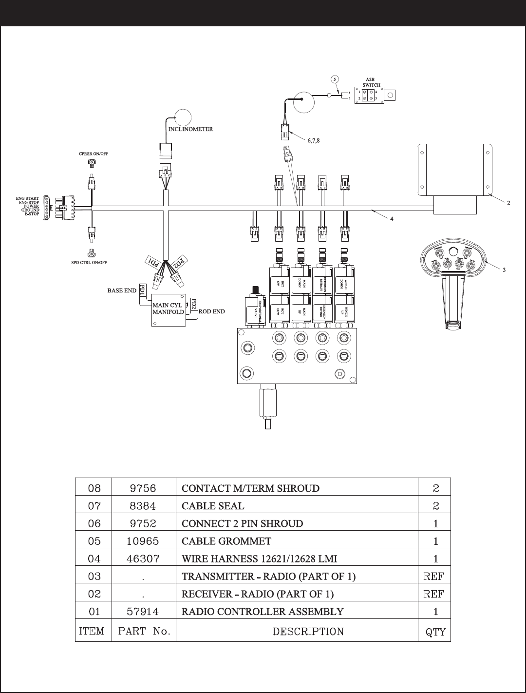
Control Kit (Flip Sheave/CDT Boost) - PN 57913
5521 Owner’s Manual
PN 59154
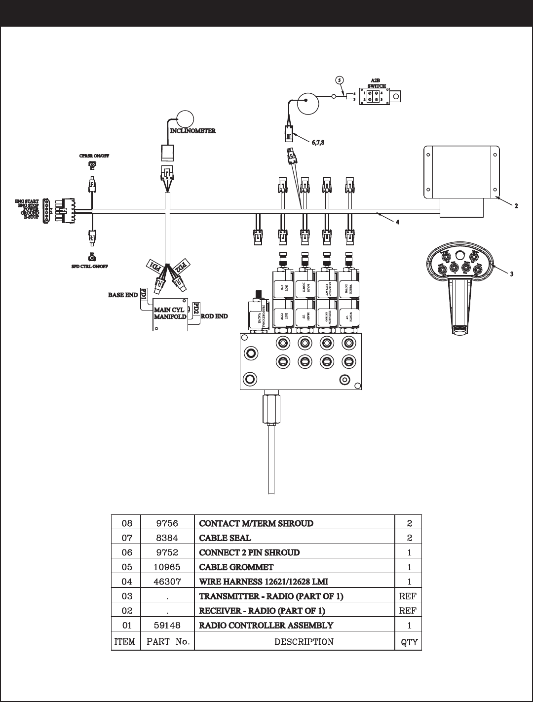
Control Kit (Flip Sheave/CDT Non-Boost) - PN 59154
Installation
PN 58276
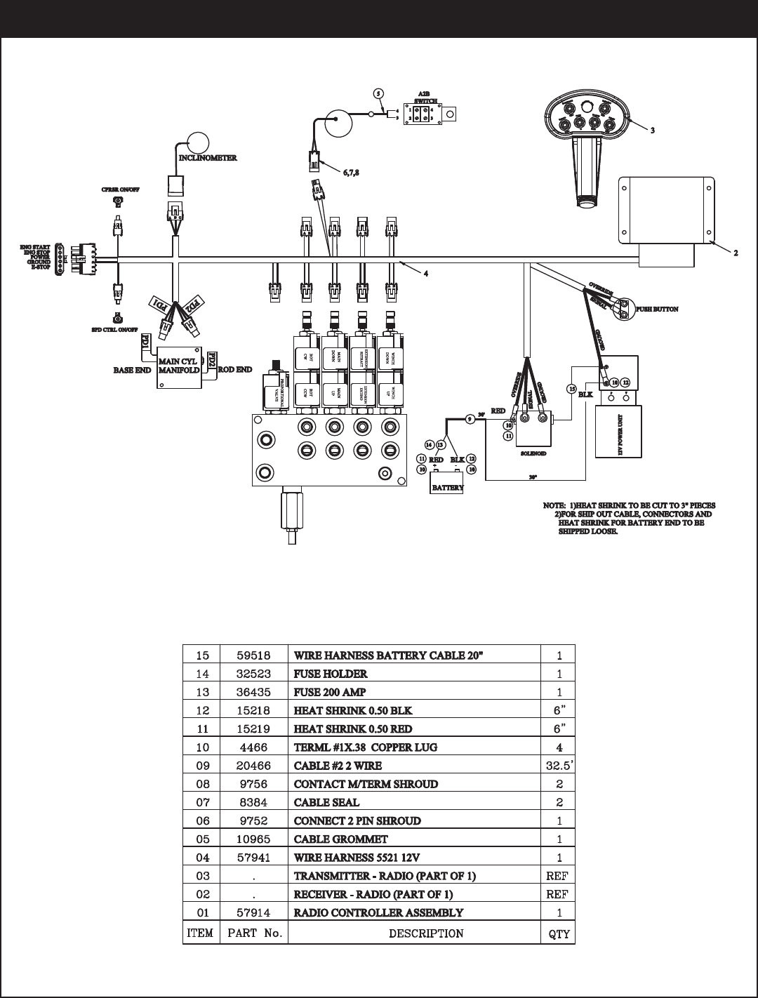
Control Kit (Flip Sheave/12V/CDT Boost) - PN 58276
5521 Owner’s Manual
PN 59522
Control Kit (Flip Sheave/12V/CDT Non-Boost) - PN 59522
Installation
PN 59138
Control Kit (Cradle A2B/CDT Boost) - PN 59138
5521 Owner’s Manual
PN 59155
Control Kit (Cradle A2B/CDT Non-Boost) - PN 59155
Installation
PN 59523
Control Kit (Cradle A2B/12V/CDT Boost) - PN 59523
5521 Owner’s Manual
PN 59524
Control Kit (Cradle A2B/12V/CDT Non-Boost) - PN 59524
Installation
+
-
FUSE 200 AMP
(STELLAR SUPPLIED)
UNDERHOOD
TRUCK BATTERY
MASTER
200 AMP
AUX BATTERY
-+
CRANE
COMPARTMENT
CAB OR CRANE
10 AMP
POWER
SWITCH
START MOTOR
SOLENOID
GROUND POST
NOTE:
MINIMUM WIRE
SIZE - 2 GA
CUSTOMER SUPPLIED
CRANE HARNESS
GROUND
GROUND
LOCATE AUX BATTERY AS
CLOSE TO CRANE AS POSSIBLE
GROUND
POWER
OPT1
OPT2
SWITCH
(NOT SUPPLIED)
POWER SOURCE FOR
RADIO REMOTE
Torque Spec
Large Nuts: 35 in-lbs
Small Nuts: 15 in-lbs
FUSE 200 AMP
(STELLAR SUPPLIED)
Wiring Diagram (Electrical Version)
5521 Owner’s Manual
NOTE: USE 32" OF HOSE PROTECTOR
P/N 17288 OVER THE ROTATION HOSES
NOTE: USE 12" OF HOSE PROTECTOR
P/N 17288 OVER THE 3 WINCH HOSES
PN 58277
Hydraulic Kit - PN 58277
Installation
NOTE: USE 32" OF HOSE PROTECTOR
P/N 17288 OVER THE ROTATION HOSES
NOTE: USE 12" OF HOSE PROTECTOR
P/N 17288 OVER THE 2 WINCH HOSES
PN 58279
Hydraulic Kit (12 Volt Version) - PN 58279
5521 Owner’s Manual
5
3
1
5
4
5
3
2
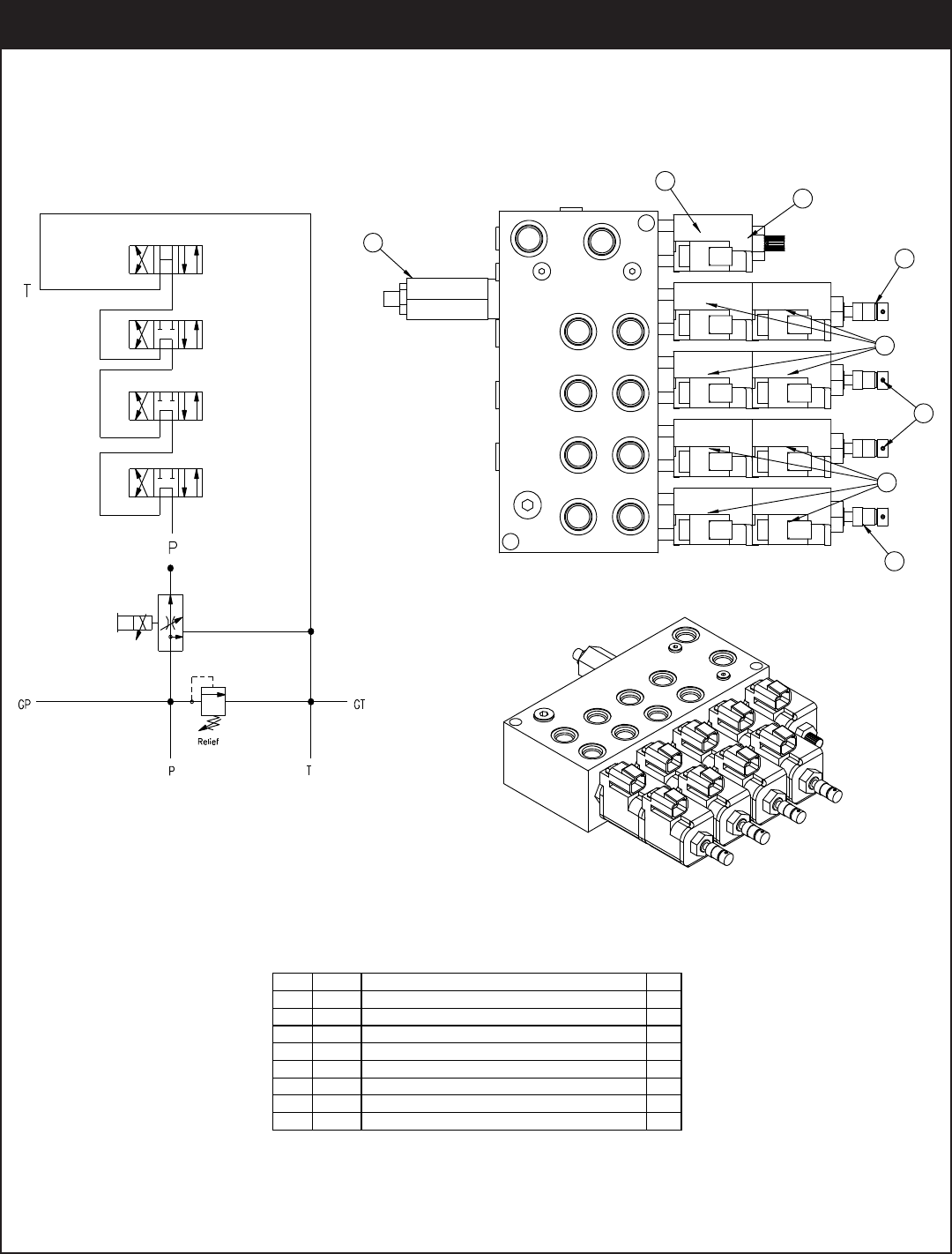
YTQNOITPIRCSEDTRAPMETI
125367 RELIEF VALVE 24685/24690 1
25368 SEAL KIT 25367
224960 VALVE FLW CTRL PRP/JP04C3150N 0-8 1
25369 SEAL KIT 24960/25381
325371 VALVE SOLND 3 POS 4 WAY TAND G04571 3
425372 VALVE SOLND 3 POS 4 WAY OPEN G04591 1
25373 SEAL KIT 25371/25372
5 44532 COIL 12VDC DUETSCH CAP012H 9
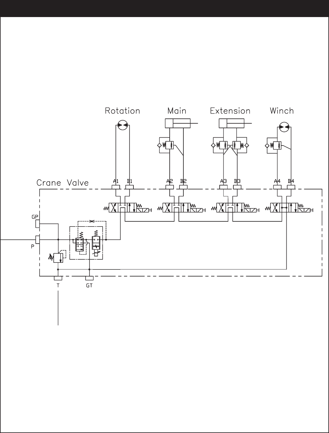
HYDRAULIC SCHEMATIC
PN 44530
Valve Bank - PN 44530
Installation
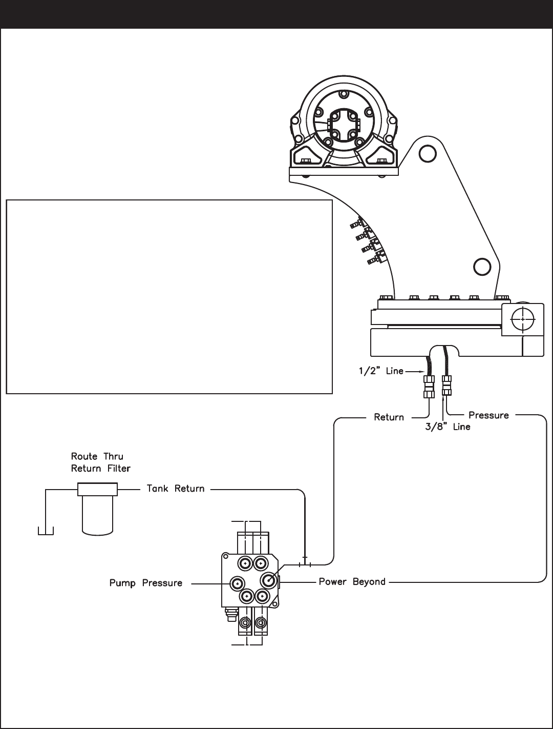
Hydraulic Installation
1. After mounting, locate the pressure and return
lines. Note: Pressure line is 3/8” hose; Return line
is 1/2” hose. Hoses are terminated using swivel
fittings.
2. Install hydraulic lines per diagram below. Note:
Stabilizer valve supplies oil to crane using the
Power Beyond feature.
3. Install hydraulic reservoir with return filter. Attach
pump pressure line to valve, return link to tank.
4. Fill system with hydraulic oil (See Stellar®
Lubrication Recommendations for fluid details).
Stabilizer Functions
Stabilizer Functions
Typical Stabilizer Valve
with Power Beyond Capabilities
5521 Owner’s Manual
Hydraulic System
Installation
Definition of Stability for the Stellar Telescopic Crane
Products:
A truck is stable until the load cannot be lifted off
the ground with the winch, without tipping over the
truck. Every Stellar crane installed must be tested for
stability to determine the actual load capacity of
the final truck package. The actual test data must
be recorded and supplied with the truck at the time
of in-service and should be kept with the truck at all
times. The following procedure will test the truck
package for stability and will provide a stability
capacity chart. The load limit information shown on
the stability capacity chart is formulated on 85%
tipping.
Set Up:
1. Locate the truck on a test course in position for
loading and engage travel brakes.
2. Set stabilizers so that they make contact with firm,
level footing.
3. Operate the crane under partial load to assure
operator proficiency and proper machine
function.
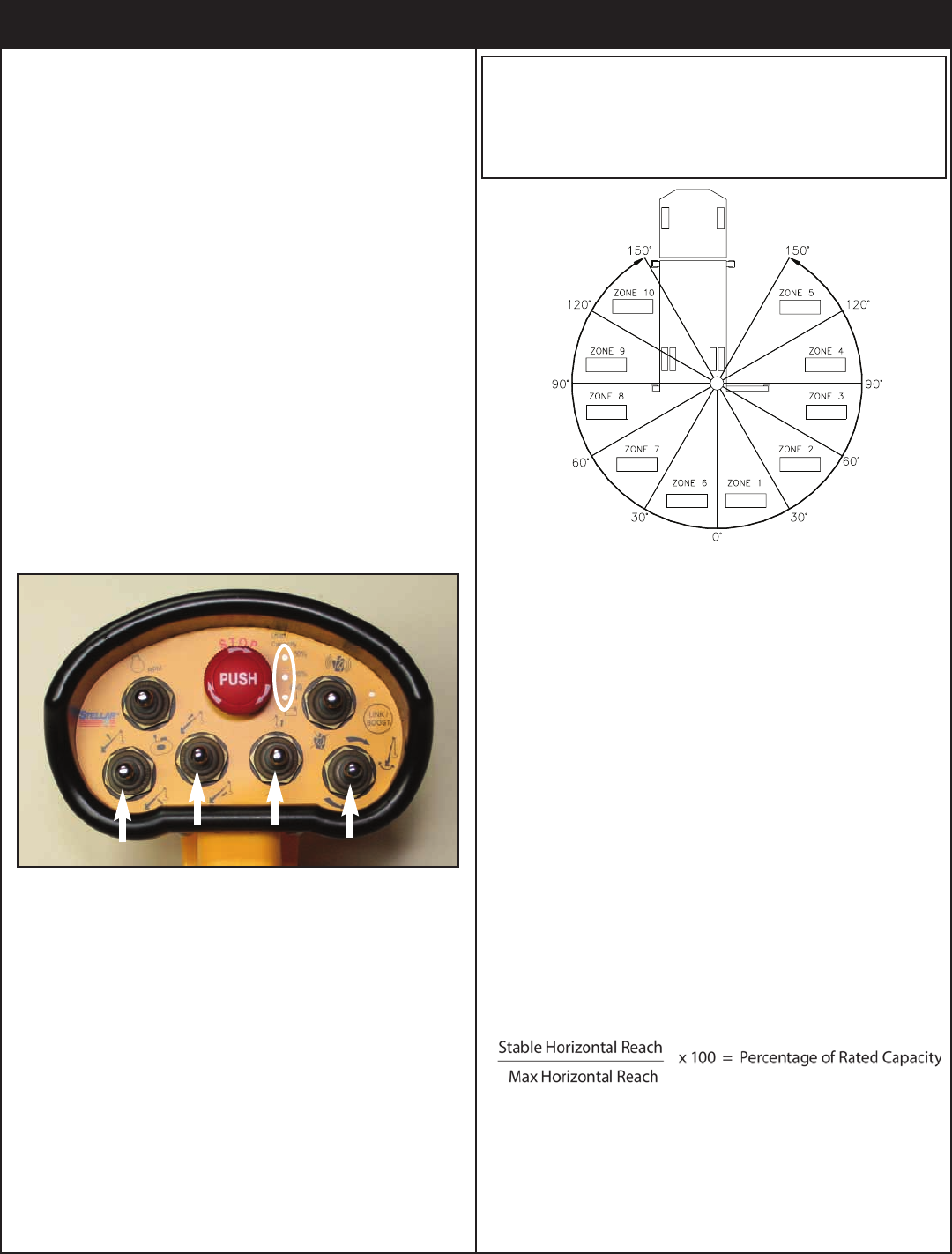
4. Put the radio into Stability Test Mode:
A. Push the bottom four switches up and hold until
all lights come on (approximately 5 seconds.)
B. At this point ,the crane will have enough
capacity to handle the weight for the stability
test.
C. The radio will timeout of stability mode after 30
minutes or when the E-Stop button is pushed.
Note: The radio can only be put into stability mode
five times. After that, the radio would have to be
returned to Stellar to be reprogrammed to allow
additional stability testing. All other radio functions
will work properly even if stability mode is not avail-
able.
Test Procedure
1. Rotate the crane into Zone 1 position.
2. With the crane fully retracted and the boom
horizontal, winch the test weight off the ground.
Note: Keep weight within six inches of the ground
at all times.
3. Extend the boom outward until full extension has
been reached or until the truck becomes unstable
(Again, use the winch to keep the weight within six
inches of the ground.)
4. If the boom goes full extension without becoming
unstable, the crane is termed stable for this zone
and 100% can be written in the Zone 1 data box.
5. If the truck becomes unstable prior to going full
extension, retract the boom until the truck
becomes stable and measure the horizontal
reach in this position (center of rotation to boom
tip). This is the stable horizontal reach for this zone.
Stable horizontal reach divided by Maximum
horizontal reach multiplied by 100 equals the
percentage of rated capacity for this zone. Use
the following formula to determine the
percentage of rated capacity:
6. Record this number in the data box for Zone 1.
This is the revised capacity due to stability for this
zone.
7. Repeat this procedure for each zone until the
worksheet is completed.
8. This is the revised capacity based on stability of
this package.
5521 Stability Data
Max Horizontal Reach: 252” (From the center of
rotation to boom tip)
Boost Stability Test Weight: 1650 lbs.
Non-Boost Stability Test Weight: 1400 lbs.
Stability Procedure
5521 Owner’s Manual
Decal Kit Placement - PN 57304
PN 57304
*USE THESE DECALS WITH BODY PACKAGE
**THESE DECALS NOT INCLUDED WITH THE DECAL KIT
ITEM
01
*04
02
*03
*05
*06
09
*07
*08
*10
*11
*12
*13
15
14
DECAL HOISTING PERSONNEL
DECAL STELLAR LOGO 6.00 X 16.50
DESCRIPTION
PART No.
52681
PART No.ITEM
QTY
*16
2
12451
DESCRIPTION QTY
1
DECAL ASME/ANSI B30.22/B30.5
DECAL GREASE WORM DRIVE BEARINGS
DECAL-ROTATION ALIGNMENT
C4545 DECAL-ELECTROCUTION 5x13
DECAL CAPACITY 5521
DECAL 5521 IDENTIFICATION57306
57598
DECAL-DANGER
DECAL-DANGERC4540
C4544
DECAL MANUAL EXT12452
4
*19
*17
2
C5910
*18
2
C5911
DECAL-STELLAR 4x9.5
DECAL-STELLAR 2x4.5
C0568
1
*20
*21
1
4214
DECAL-DIESEL
DECAL-SERVICE
9188 DECAL-ROTATE/GREASE
DECAL-DANGER
DECAL-ELECTROCUTION 2x2.754186
4189
DECAL-DANGER
DECAL-DANGER O.R.
4190
C4795
4188
1
24
22
1
12300
*23
1
C4541
DECAL-TWO BLOCKING
DECAL-CRANE STOWING
15171
1
25
26
2
15172
1
1
3
2
1
1
1
1
1
1
DECAL VB CONTROL MECH CRANE
DECAL STELLAR MADE IN THE USA
DECAL SNATCH BLOCK CAP 5 TON
DECAL WARNING OVERLOAD DEVICE
DECAL CAUTION STOW HOOK
41068
31
DECAL-ELECTROCUTION 4.5x7.5
DECAL-DANGER MOVING O.R.C5918
C1179
DECAL-ANGLE INDICATOR SS
DECAL ANGLE INDICATOR CS
D1197
D1196
27
2
24712
28
2
28256
35234
30**
1
29
1
38472
1
1
1
1
1
32 25159 DECAL WARNING MANUAL OVERRIDES 1
33 54588 DECAL CDT 2.00X2.00 2
1
2
®®
5521
3
26
14,15
27
22
29
28
30
25
9
60
50
0
20
30
10
40
Angle Indicator
80
70
33
Assembly Drawings
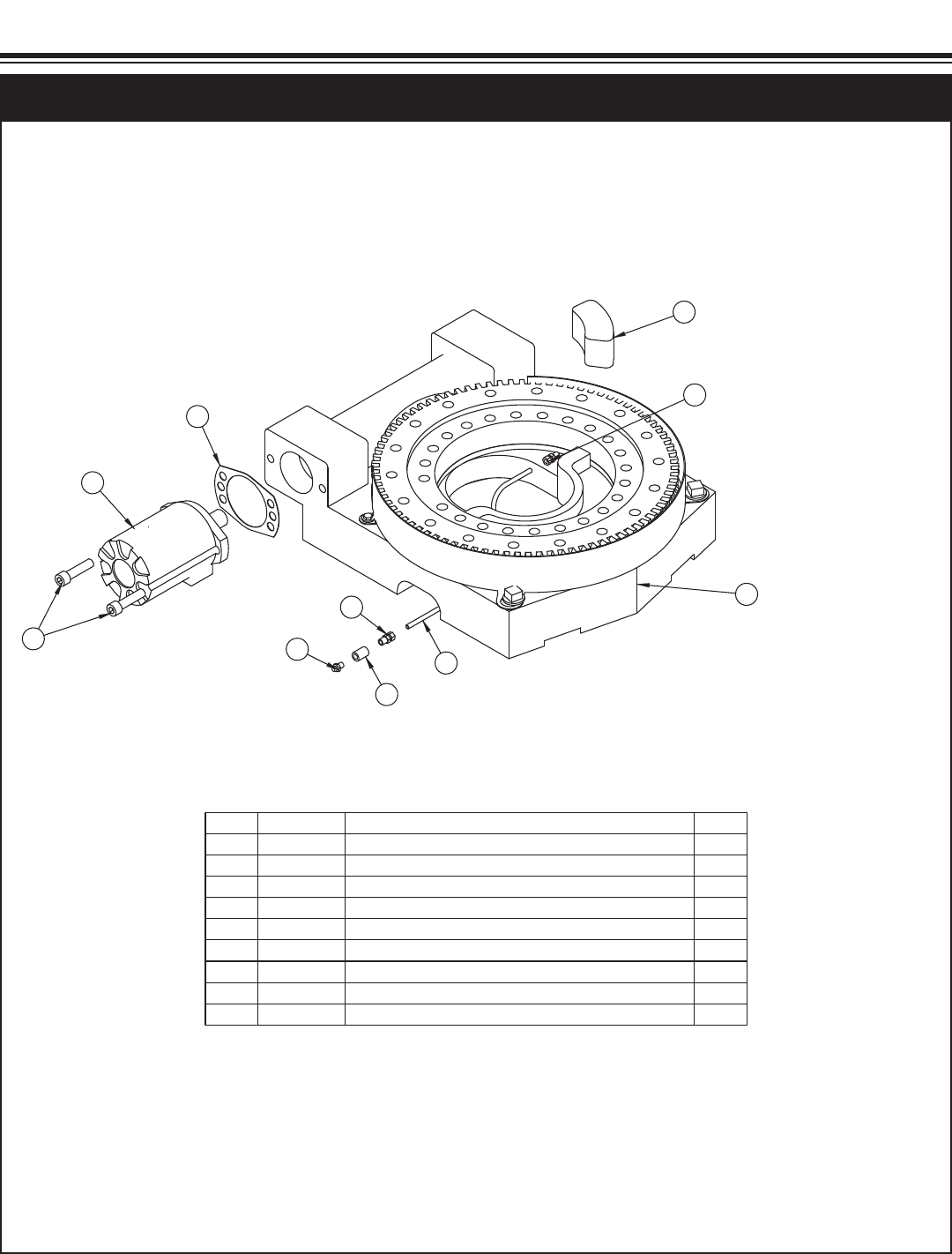
.YTQNOITPIRCSEDTRAPMETI
1 47869 BEARING SWING DRIVE CAST 6620 GEARTEK 1
1EDILS 004 0283 POTS245112
3C6069 MOTOR HYD ROSS MK080613AAAB1
11-65001-800 ROTOM TEKSAG151124
5D1345 FTG CPRSN 0.12NPT/0.25 TUBE2
6D1810 TBE AIR SAEJ844 TYPE A .25 (RM)1
131.0 EPIP RELPUOC GTF6522C7
8 56589 ZERK 1/8 NPT STRAIGHT LONG THREAD 1
2HS 00.2X31-05.0 RCS PAC594359
NOTE: ITEMS 1 INCLUDE GUARD & GUARD FASTENERS
8
2
3
GASKET SHOWN AS REFERENCE
4
5
6
5
7
9
1
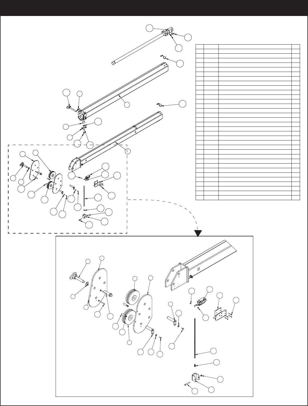
PN 50364
Base Assembly - PN 50364
Chapter 3 - Assembly Drawings
5521 Owner’s Manual
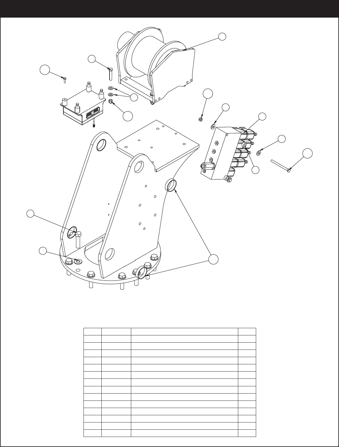
PN 57577
.YTQNOITPIRCSEDTRAPMETI
11255 TSAM692751
2 21528 WINCH 2500 5520 CRANE1
3C1026 CAP SCR 0.63-11X2.50 HHGR8 14
4C1006 CAP SCR 0.38-16X2.00 HHGR84
5C5902 WASHER 0.63 SAE FLAT YELLOW GR814
6 0343 WASHER 0.31 USS FLAT ZINC5
7C6353 WASHER 0.38 SAE FLAT YELLOW GR88
827813 COLLAR 0.38X0.75X0.38 UHMW2
9 44530 VB 4 SECT W/PROP STER8GPM DEUTSCH1
10 0342 NUT 0.31-18 HHGR5 NYLOC 2
11 56673 NUT 0.38-16 HHGR8 NYLOC 4
12 57594 BUSHING COMPOSITE MRP 2.00X.504
14 0491 CAP SCR 0.31-18X4.00 HHGR52
15 47425 CAP SCR 6MMX20MM HH 8.8(GR5)4
9
3
5
14
6
6
10
2
4
7
11
15
12
8
Mast Assembly - PN 57577
Assembly Drawings
33
15
19
423
17
22 21
14
13
20
23
25
26
24
32
12
7
3
6
5
16
16
10
1
11
2
8
9
23 4
3
4
20
20
23
26
27
22
30
29
20
4
23
31
28
18
2BUSHING BPC16DXR24 1.00X1.50006815
2PIN CAP 0.44X1.75X0.19 SS932014
1ZERK 1/8 NPT STRAIGHTc159213
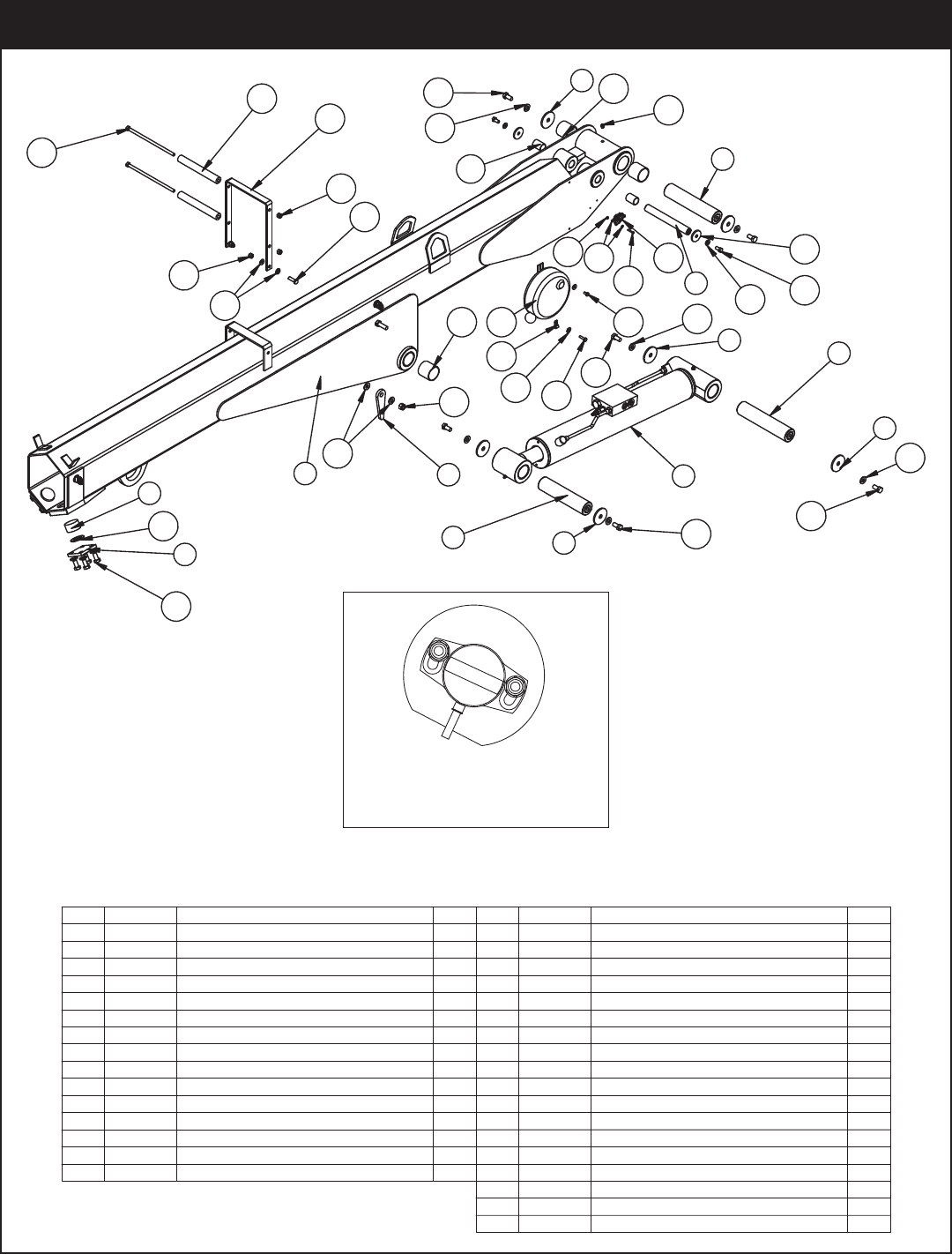
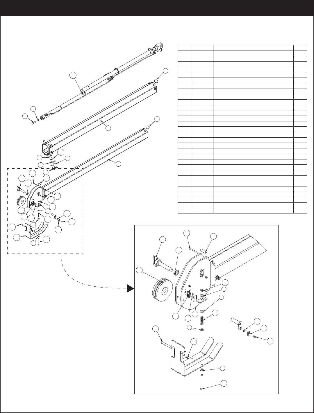
.YTQNOITPIRCSEDTRAPMETI
11255 MOOB RENNI782751
2 54942CYLINDER ASM 6620 INNER CDT1
2T&D 36.9X00.2 NIPPZ312623
691.0X05.2X65.0 PAC NIP24194
1T&D 88.8X00.2 NIPPZ11795
1T&D 83.8X00.1 NIPPZ21796
7D1194PC PLATE ANGLE INDICATOR 2
8 9363 WEAR PAD 1.12X2.00 RND NYLATRON2
9 9545PC PLATE WEAR PAD SUPPORT2
10269 EDIUG EPOR TKRBCP5343101
11 27720 SPACER ROPE GUIDE 6620 UHMW2
10266 LEER DROC4451121
.YTQNOITPIRCSEDTRAPMETI
16 4381BUSHING BPC32DXR32 2.00X2.00 4
17 0340 WASHER 0.25 USS FLAT ZINC2
18 0478 CAP SCR 0.25-20X0.50 HHGR51
19 C6106 NUT 0.50-13 HHGR5 NYLOC 2
20 D0790 WASHER 0.50 SAE FLAT YELLOW GR818
21 9843 CAP SCR 0.38-16X0.75 HHGR82
22 C6353 WASHER 0.38 SAE FLAT YELLOW GR86
23 10172 CAP SCR 0.50-13X1.00 HHGR814
24 12168 CAP SCR 0.38-16X9.00 HHGR52
25 0335 CAP SCR 0.38-16X1.25 HHGR52
26 0347 NUT 0.38-16 HHGR5 NYLOC 4
1GED 06 RETEMONILCNI3943572
28 18765 WASHER #6 SAE FLAT ZINC4
2SS COLYN HH 23-6# TUN6700D92
30 18618 SCREW #6-32X1.00 PHMS PH2
31 0425 MACHY WASHER 1.25ID 10GA2
32 0480 CAP SCR 0.25-20X1.00 HHGR51
1LYNIV KLB 52.0 PMALC6065C33
NOTE: INCLINOMETER MOUNTS
INSIDE THE BOOM. VIEW SHOWS
POSITION OF INCLINOMETER
PN 57581
Main Boom Assembly - PN 57581
5521 Owner’s Manual
22
28
30
20
31
15
12
4
7
5
9
10
17
18
13
32
11
8
3
16
14
6
2
1
19
31
14
29
25 26 21
27
24
17 23
PN 57593
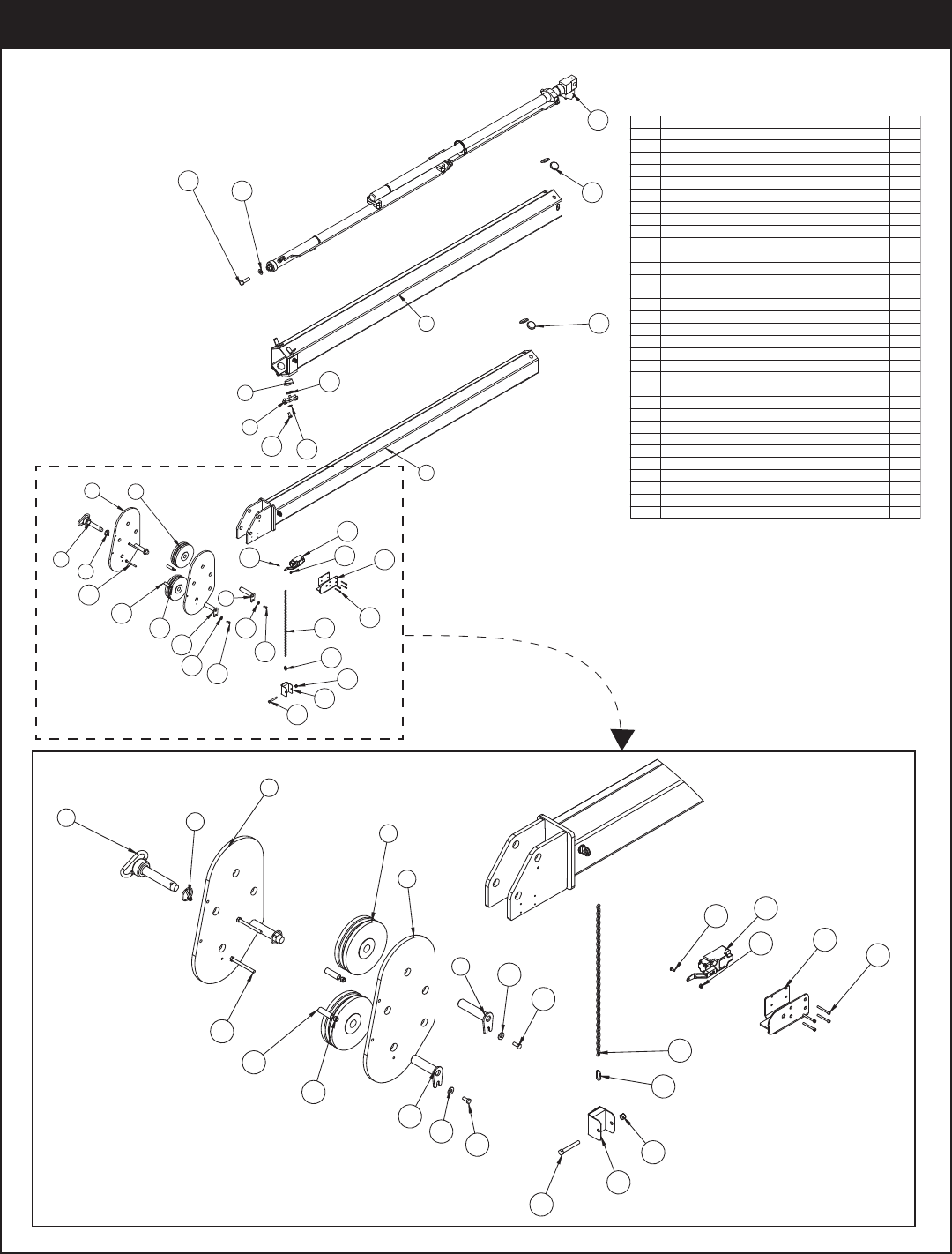
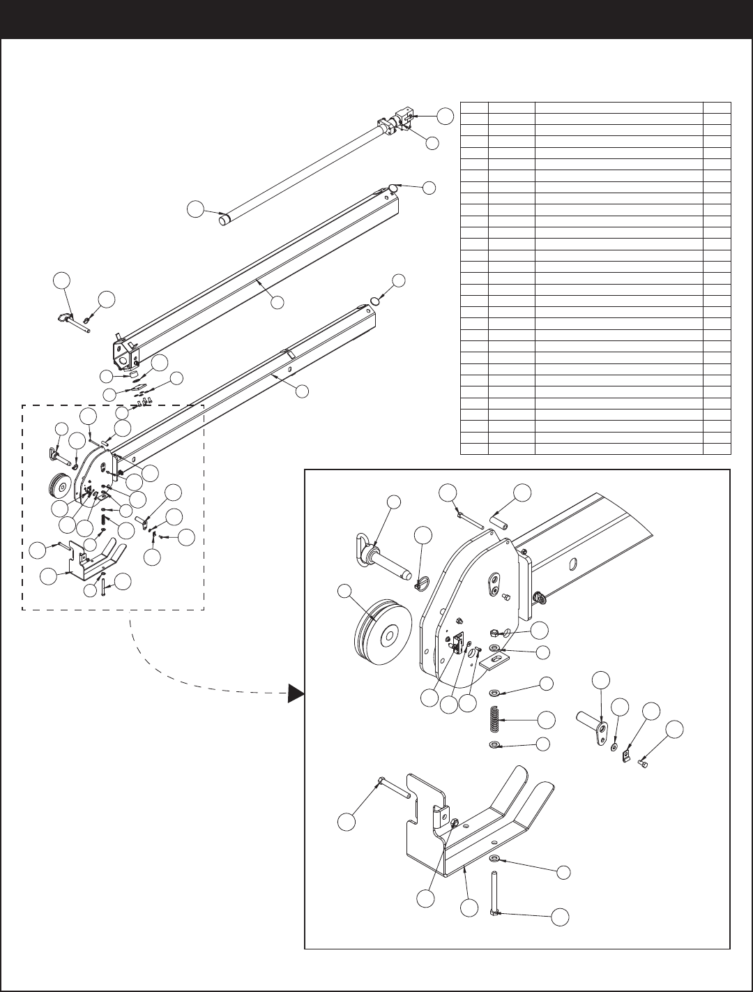
.YTQNOITPIRCSEDTRAPMETI
11255 TS1 MOOB TXE703751
2 50341EXT BOOM 2ND 6621 FLIP SHEAVE 1
3 12929PC PLATE SHEAVE MOUNTING 2
205.4X00.1 HCTIH NIP428214
2HCNYL 65.1X91.0 NIP35755
69363 WEAR PAD 1.12X2.00 RND NYLATRON2
7 9545PC PLATE WEAR PAD SUPPORT2
8 11545 SHEAVE 6620 6.75 DIA .31R/1.94 THK2
9 13400 PIN TEAR DROP 1.00X4.38 1
10 13399 PIN TEAR DROP 1.00X3.81 1
11 27719SPACER BOOM TIP 6620 UHMW2
12 10172 CAP SCR 0.50-13X1.00 HHGR88
13 0490 CAP SCR 0.31-18X3.50 HHGR52
14 0420 CAP SCR 0.31-18X0.75 HHGR5 2
15 D0790 WASHER 0.50 SAE FLAT YELLOW GR88
16 C6219 WASHER 0.75 SAE FLAT YELLOW GR81
17 0343 WASHER 0.31 USS FLAT ZINC2
18 0342 NUT 0.31-18 HHGR5 NYLOC 2
19 0425 MACHY WASHER 1.25ID 10GA2
20 49316 CYLINDER EXT ASM 6620 2.0/2.01
21 34354PC ANTI 2 BLOCK COVER LH 1
22 11938 SWITCH LIMIT A2B FURNAS 3SE31701
23 33749 CAP SCR #10-24X1.75 SH4
105.12X501.0 NIAHC4548142
25 D1711 CAP SCR #10-24X0.50 BTNHD SS1
26 C4956 NUT #10-24 HH NYLOC SS1
27 37850 CONNECTOR QUICK LINK 0.131
1KCOLB 2 ITNA THGIEWCP4625382
29 0530 CAP SCR 0.38-16X2.75 HHGR51
30 0347 NUT 0.38-16 HHGR5 NYLOC 1
31 6252 WEAR PAD 0.34X2.50 RND NYLATRON4
32 4974 CAP SCR 0.75-10X2.50 HHGR8 RED PATCH1
17
22
25
26 21
23
24
27
30
28
29
45
3
13
11
8
3
18
10
17
14
9
14
Extension Boom Assembly (Flip Sheave) - PN 57593
Assembly Drawings
PN 58290
.YTQNOITPIRCSEDTRAPMETI
11255 TS1 MOOB TXE703751
2 51117 EXT BOOM 6620 2ND CRADLE A2B 1
3C6219WASHER 0.75 SAE FLAT YELLOW GR81
4 4974 CAP SCR 0.75-10X2.50 HHGR8 ZY1
59363 WEAR PAD 1.12X2.00 RND NYLATRON2
6 9545PC PLATE WEAR PAD SUPPORT2
618RG TALF 05.0 REHSAW0970D7
8 10172 CAP SCR 0.50-13X1.00 HHGR8 ZY8
99991 WEAR PAD 0.19X2.50 RND NYLATRON4
10 11545 SHEAVE 6620 6.75 DIA .31R/1.94 THK 2
105.4X00.1 HCTIH NIP4282111
1HCNYL 65.1X91.0 NIP357521
13 9706ZP PIN TEAR DROP 1.00X3.252
14 0343WASHER 0.31 USS FLAT ZINC 2
15 0420 CAP SCR 0.31-18X0.75 HHGR51
16 0484 CAP SCR 0.31-18 X 0.50 HHGR5 1
17 27719SPACER BOOM TIP 6620 UHMW2
18 12178 CAP SCR 0.31-18X3.25 HHGR52
2COLYN HH 81-13.0 TUN243091
20 27710 SPRING ANTI 2 BLOCK SUMMIT2
21 C6106 NUT 0.50-13 HHGR5 NYLOC 3
22 0506 CAP SCR 0.50-13X4.00 HHGR51
23 31132 SCREW #10-24X0.50 SH SS2
24 D0178 WASHER #10 SAE FLAT ZINC2
1LYNIV KLB 13.0 PMALC9721352
26 35105 SWITCH LIMIT E1117-B9111-6C1
27 49316 CYLINDER EXT ASM 6620 2.0/2.01
28 0425MACHY WASHER 1.25ID 10GA2
29 51903PC PLATE CRADDLE 6620/66281
30 C1000 CAP SCR 0.50-13X5.00 HHGR52
2
1
9
9
27
4
3
5
28
6
7
8
17
18
19
11
12
22
29 30
7
7
20
21
23
24
26
15
25
14
7
16
7
17
18
11
12
10
23
24
26
7
7
21
20
7
14
25
15
22
21
30
Extension Boom Assembly (Cradle A2B) - PN 58290
5521 Owner’s Manual
.YTQNOITPIRCSEDTRAPMETI
1M1H1 1255 TS1 MOOB TXE529751
2 57930 EXT BOOM 2ND 5521 FLIP SHEAVE 1H1M1
2GNITNUOM EVAEHS ETALPCP929213
205.4X00.1 HCTIH NIP428214
3HCNYL 65.1X91.0 NIP35755
69363WEAR PAD 1.12X2.00 RND NYLATRON2
2TROPPUS DAP RAEW ETALPCP54597
8 11545 SHEAVE 6620 6.75 DIA .31R/1.94 THK2
183.4X00.1 PORD RAET NIPPZ004319
118.3X00.1 PORD RAET NIPPZ9933101
11 27719SPACER BOOM TIP 6620 UHMW2
12 10172 CAP SCR 0.50-13X1.00 HHGR88
13 0490 CAP SCR 0.31-18X3.50 HHGR52
14 0420 CAP SCR 0.31-18X0.75 HHGR5 2
15 D0790 WASHER 0.50 SAE FLAT YELLOW GR88
16 0343 WASHER 0.31 USS FLAT ZINC2
17 0342 NUT 0.31-18 HHGR5 NYLOC 2
18 0425 MACHY WASHER 1.25ID 10GA2
1HL REVOC KCOLB 2 ITNA CP4534391
20 11938 SWITCH LIMIT A2B FURNAS 3SE31701
4HS 57.1X42-01# RCS PAC9473312
105.12X501.0 NIAHC4548122
23 D1711 CAP SCR #10-24X0.50 BTNHD SS1
1SS COLYN HH 42-01# TUN6594C42
25 37850 CONNECTOR QUICK LINK 0.131
1KCOLB 2 ITNA THGIEWCP4625362
27 0530 CAP SCR 0.38-16X2.75 HHGR51
28 0347 NUT 0.38-16 HHGR5 NYLOC 1
29 6252 WEAR PAD 0.34X2.50 RND NYLATRON4
30 57936 CYLINDER ASM 5521 MANUAL1
31 C4813 WASHER 0.56 SAE FLAT YELLOW GR84
32 9004 CAP SCR 0.50-13X1.75 HHGR84
100.8X57.0 HCTIH NIP7397533
30
29
15
12
4
7
5
16
17
13
11
8
3
14
6
2
1
18
29
14
16
27 26
28
25
22
23
20
24 19
21
5
33
32
31
PN 57935
19
43
5
3
8
13 13
11
17
8
3
9
10 16 14
16
14
27 26
28
25
22
20
23
24
21
Extension Boom Assembly (Flip Sheave - 1 Hyd/1 Manual) - PN 57935
Assembly Drawings
.YTQNOITPIRCSEDTRAPMETI
1 57925 EXT BOOM 1ST 5521 1H1M1
2 59147 EXT BOOM 6620 2ND CRADLE A2B 1
39363 WEAR PAD 1.12X2.00 RND NYLATRON2
4 9545PC PLATE WEAR PAD SUPPORT2
028RG TALF 05.0 REHSAW0970D5
6 10172 CAP SCR 0.50-13X1.00 HHGR8 ZY8
79991 WEAR PAD 0.19X2.50 RND NYLATRON4
8 11545 SHEAVE 6620 6.75 DIA .31R/1.94 THK 2
105.4X00.1 HCTIH NIP428219
2HCNYL 65.1X91.0 NIP357501
11 9706ZP PIN TEAR DROP 1.00X3.252
12 0343WASHER 0.31 USS FLAT ZINC 2
13 0420 CAP SCR 0.31-18X0.75 HHGR51
14 0484 CAP SCR 0.31-18 X 0.50 HHGR5 1
15 27719SPACER BOOM TIP 6620 UHMW2
16 12178 CAP SCR 0.31-18X3.25 HHGR52
2COLYN HH 81-13.0 TUN243071
18 27710 SPRING ANTI 2 BLOCK SUMMIT2
19C6106 NUT 0.50-13 HHGR5 NYLOC 3
20 0506 CAP SCR 0.50-13X4.00 HHGR51
21 31132 SCREW #10-24X0.50 SH SS2
22 D0178 WASHER #10 SAE FLAT ZINC2
1LYNIV KLB 13.0 PMALC9721332
24 35105 SWITCH LIMIT E1117-B9111-6C1
25 0425 MACHY WASHER 1.25ID 10GA2
26 51903PC PLATE CRADDLE 6620/66281
27 C1000 CAP SCR 0.50-13X5.00 HHGR52
28 57936 CYLINDER ASM 5521 MANUAL1
29 9004 CAP SCR 0.50-13X1.75 HHGR84
100.8X57.0 HCTIH NIP7397503
PN 59146
2
1
7
7
28
30
10
3
25
4
5
6
15
16
17
9
10
20
26 27
5
5
18
19
21
22
24
13
23
12
14
5
29
5
11
22
27
5
26
20
19
13
23
12
11
8
9
10
16 15
19
5
5
18
5
24 21
Extension Boom Assembly (Cradle A2B - 1 Hyd/1 Manual) - PN 59146
5521 Owner’s Manual
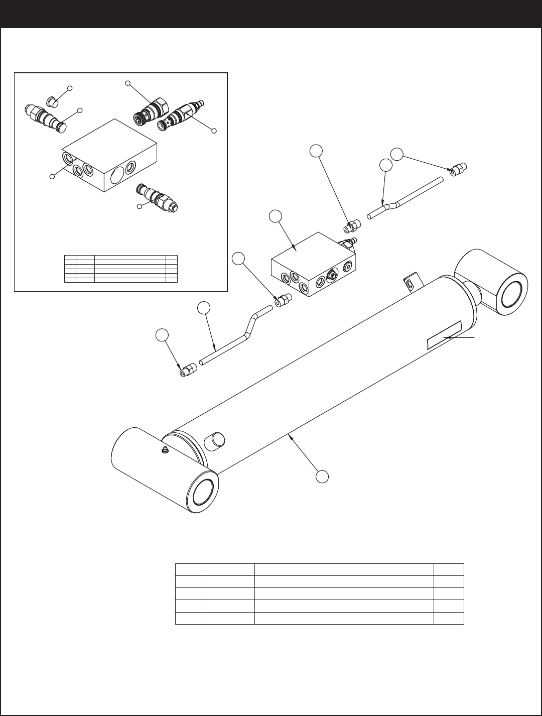
PN 54942
.YTQNOITPIRCSEDTRAPMETI
1 50918 CYLINDER INNER 4.00X21.38 NEW MAST1
2 41910 MANIFOLD ASM DUAL 10-1CBAL-RLF-CHK1
3 44066 TUBE ASM 0.38X8.25 MAIN 10628/126282
4S-OLO5F-6 TPADA GTF97204
4
3
1
4
3
4
2
4
Cylinder
Serial Tag
Location
Note: Main Cylinder uses
Stellar Seal Kit PN 17724
Manifold Assembly
PN 41910
2
3
5
4
1
4
.YTQNOITPIRCSEDTRAPMETI
1 39425 MANIFOLD CBAL DOUBLE T11A WITH RELIEF1
1NCX-DEXC KCEHC EVLAV809142
1ISP 008 NAL-ADDR EVLAV709143
4 9803 Valve C- SUN CBBD-LJN-35002
5C4961PLUG STR HOLLOW HEX 0.38 6-HP5ON1
Main Cylinder Assembly - PN 54942
Assembly Drawings
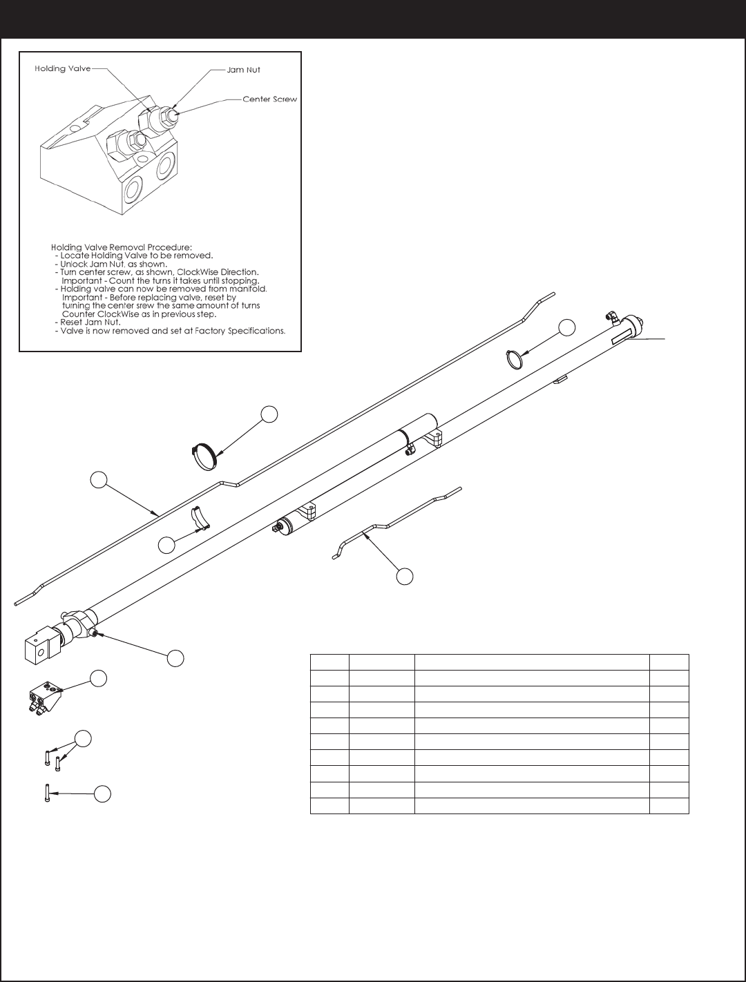
.YTQNOITPIRCSEDTRAPMETI
137548 CYLINDER EXT 2 STAGE 2.0/2.0 PTD 60 1
214115 MANIFOLD ASM 6620 EXT CBBD-LJN-XVN 1
3 11882 CAP SCR 0.38-16X1.75 SH ZC 2
414601 CAP SCR 0.38-16X2.25 SH ZC 1
514442 TUBE ASM 0.38X23.25 EXT CYL 6620 1
614443 TUBE ASM 0.38X102.25 EXT CYL 6620 1
724729 HOSE CLAMP #52 3.00 - 3.75 1
818701 CLAMP PORT TUBE ZR518 1
1 P #36 WRM GEARMALC ESOHD06559
8
2
4
1
5
6
7
3
9
PN 49316
Cylinder
Serial Tag
Location
Extension Cylinder Uses:
Upper Seal Kit - PN 54778
Lower Seal Kit - PN 20310
Extension Cylinder Assembly - PN 49316
5521 Owner’s Manual
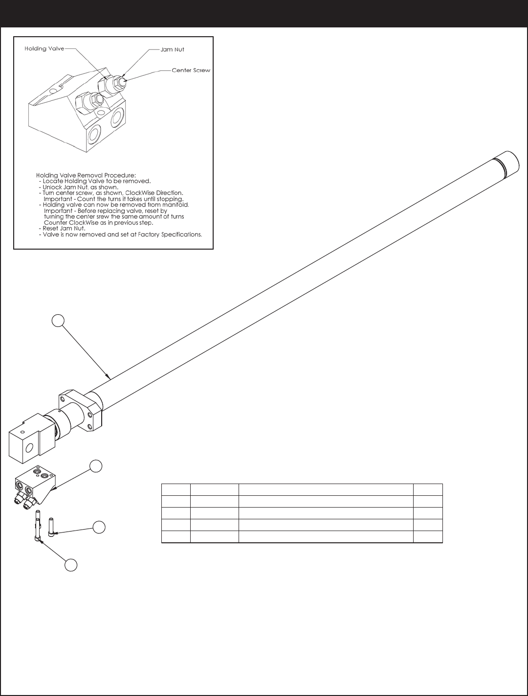
.YTQNOITPIRCSEDTRAPMETI
1 57932 CYLINDER 2.00X60.00 5521 MANUAL1
2 14115MANIFOLD ASM 6620 EXT CBBD-LJN-XVN 1
3 11882 CAP SCR 0.38-16X1.75 SH ZC2
4 14601 CAP SCR 0.38-16X2.25 SH ZC1
PN 57936
3
1
2
4
Extension Cylinder Assembly (1 Hyd/1 Manual) - PN 57936
Assembly Drawings
PN 57597
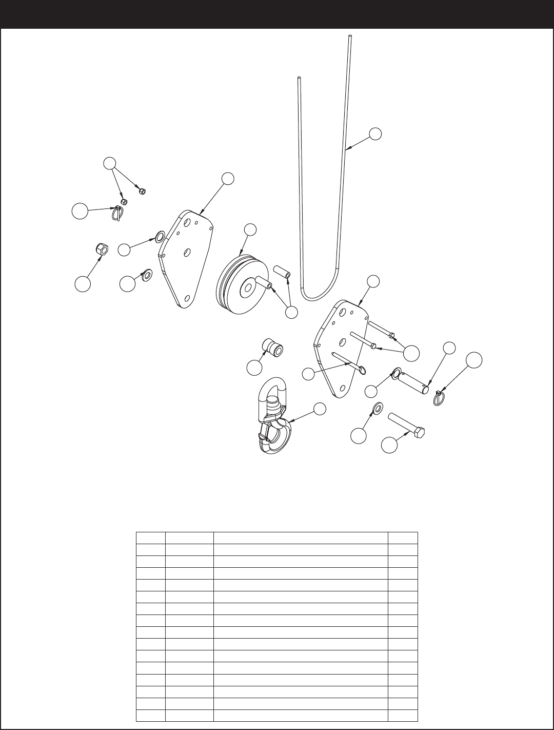
.YTQNOITPIRCSEDTRAPMETI
1 11545 SHEAVE 6620 6.75 DIA .31R/1.94 THK 1
2 57596PC PLATE SNATCH BLOCK 55212
3 13436 PIN .38X4.00 QUICK RELEASE 1
4 25831 HOOK 5 TON SWIVEL CROSBY 10286231
5 9610 WIRE ROPE 0.31 6X19 IWRC-XIP 90FT1
1RETTOC 60.4X00.1 NIPPZ478936
7 0867 MACHY WASHER 1.00ID 14GA2
200.2X57.0X44.0 RALLOCCP346448
9 0347 NUT 0.38-16 HHGR5 NYLOC 2
2HCNYL 65.1X91.0 NIP357501
1KOOH V GNIHSUB4489311
12 C6219 WASHER 0.75 SAE FLAT YELLOW GR82
13 5841 CAP SCR 0.75-10X4.50 HHGR8 1
14 C0538 NUT 0.75-10 HHGR8 NYLOC 1
15 0531 CAP SCR 0.38-16X3.50 HHGR52
10
13
5
14 12
4
11
1
2
12
7
3
9
6
10
15
2
7
8
Cable & Hook Assembly - PN 57597
5521 Owner’s Manual
10
34
1
5
7
2
8
6
8
10
6
6
9
PN 57939
.YTQNOITPIRCSEDTRAPMETI
1 19997PC COVER POWER UNIT 55201
2 16994POWER UNIT 12V 5520 HORZ 1
3 17771 SWITCH PUSH BUTTON 9216-031
4 18472 DECAL MANUAL OPERATION 55201
5 0340 WASHER 0.25 USS FLAT ZINC2
6C6353 WASHER 0.38 SAE FLAT YELLOW GR816
7 0479 CAP SCR 0.25-20X0.75 HHGR52
8 56673 NUT 0.38-16 HHGR8 NYLOC 8
9 59136 BRACKET POWER UNIT 55211
10 16962 CAP SCR 0.38-16X1.50 HHGR88
Power Unit Assembly - PN 57939
Assembly Drawings
PN 56647
.YTQNOITPIRCSEDTRAPMETI
1 20088 CONTROL HANDLE HOUSING 4 FCTN HET1
2 56657 CONTROL HANDLE FACE PLT W/LABEL 6 FCTN CDT 1
1NTCF 4 HCTIWS OIDAR DRAUG583423
4 35447 CONTROL HANDLE GRIP W/TRIGGER HT H21
524958RUBBER BOOT TRIGGER GUARD HET1
6 22600 SWITCH TOGGLE HET RADIO 630193006
7 35441 BATTERY TUBE AA HETRONIC RADIO1
1LX AVON POTS E HCTIWS658748
3
SEE NOTE
7
5
4
1
2
8
6
NOTE: 1) P/N'S 25999 & 24958 ARE OPTIONAL COVERS
FOR THE SWITCHES AND TRIGGER
CDT™ Radio Transmitter Assembly - PN 56647
5521 Owner’s Manual

Replacement Parts
Chapter 4 - Replacement Parts
PART# DESCRIPTION
C6069 HYDRAULIC SWING MOTOR
25367 RELIEF VALVE
25368 SEAL KIT - RELIEF VALVE
24960 FLOW CONTROL VALVE
25369 SEAL KIT - FLOW CONTROL VALVE
25371 SOLENOID VALVE TAND G04571
25373 SEAL KIT - SOLENOID VALVE
44532 COIL - 12VDC
9803 C-BALANCE VALVE
28485 PRESSURE TRANSDUCER
C2027 O'RING - # 4 FACE SEAL
C2028 O'RING - # 6 FACE SEAL
C2029 O'RING - # 8 FACE SEAL
D1245 O'RING - # 4 SAE
D1246 O'RING - # 6 SAE
D1247 O'RING - # 8 SAE
17724 SEAL KIT - MAIN LIFT CYLINDER
54778 SEAL KIT - EXTENSION CYLINDER (UPPER CYLINDER)
20310 SEAL KIT - EXTENSION CYLINDER (LOWER CYLINDER)
44066 TUBE ASM - MAIN CYLINDER
14442 TUBE ASM - EXTENSION CYLINDER
14443 TUBE ASM - EXTENSION CYLINDER
55827 WORM GEAR - BEARING SWING DRIVE
55829 BEARING & SEAL KIT - BEARING SWING DRIVE
55830 WORM / BEARING & SEAL KIT - BEARING SWING DRIVE
4381 BUSHING 2.00" X 2.00"
0068 BUSHING 1.00" X "1.50
44533 BUSHING 2.00" X 0.75"
9363 WEAR PAD - 2.00" ROUND
6252 WEAR PAD - 2.50" ROUND
9320 PIN CAP .44 X 2.50 X .25
9142 PIN CAP .56 X 2.50" X 0.25" SS
10172 CAP SCR. 0.50-13 X 1.00"
9843 CAP SCR. 0.38-16 X 0.75" GR8
C6353 WASHER 0.38 FLAT GR8
D0790 WASHER 0.50 FLAT GR8
11545 SHEAVE
9610 WIRE ROPE
12824 HITCH PIN 1.00" X 4.50"
57937 HITCH PIN 0.88" X 8.00"
13436 QUICK RELEASE PIN .38 X 4.00"
5753 LYNCH PIN
53493 INCLINOMETER 60 DEGREE
11938 LIMIT SWITCH (CHAIN & WEIGHT) ANTI-2-BLOCK
31670 WEIGHT & CHAIN ASSY - ANTI-2-BLOCK
35105 LIMIT SWITCH (BAR TYPE) ANTI-2-BLOCK
43488PC CRADLE PLATE - ANTI-2-BLOCK (CRADLE/BASKET STYLE)
61048 CRADLE FS/CRADLE A2B (After 8/1/2011)
27710 SPRING - LIMIT SWITCH CRADLE / BASKET
11544 CORD REEL
56647 RADIO TRANSMITTER (HETRONIC RADIO)
35441 BATTERY TUBE (AA) HOLDER (HETRONIC RADIO)
47856 E-STOP SWITCH (HETRONIC RADIO)
22600 TOGGLE SWITCH (HETRONIC RADIO)
35447 HANDLE / TRIGGER ASM (HETRONIC RADIO)
35916 BACK UP CABLE CONTROL - HETRONIC RADIO SYSTEM
18468 12V SOLENOID (12V POWER UNIT ASSEMBLY)
24956 12V SOLENOID (12V POWER UNIT ASSEMBLY)
17771 PUSH BUTTON (12V POWER UNIT ASSEMBLY)
25831 HOOK - 5 TON
19501 SAFETY LATCH FOR 5 TON SWIVEL HOOK
C1592 GREASE ZERK
4460 GEAR BEARING GREASE - MOLUBE (Open Teeth)

Limited Warranty Statement
Stellar Industries, Inc. (Stellar) warrants products designed and manufactured by Stellar to be free from defects in material and workmanship under
proper use and maintenance. Products must be installed and operated in accordance with Stellar’s written instructions and capacities. This warranty
shall cover the following:
Stellar Cranes, Stellar Hooklift Hoists, Stellar Cable Hoists, Stellar Container Carriers, Stellar Service Trucks, and Stellar X-Tra-Lift Systems:
Twelve (12) month warranty on parts from the date recorded by Stellar as the in-service date, not to extend beyond twenty-four (24) months from date
ofmanufacture,
Twelve (12) month repair labor from the date recorded by Stellar as the in-service date, not to extend beyond twenty-four (24) month from date of
manufacture, and
Thirty-six (36) month warranty on all Stellar Manufactured structural parts from the date recorded by Stellar as the in-service date, not to extend beyond
forty-eight (48) months from date of manufacture.
Stellar Tarper Systems:
Twelve (12) month warranty on parts from the date recorded by Stellar as the in-service date, not to extend beyond twenty-four (24) months from date
of manufacture and
Three (3) month repair labor from the date recorded by Stellar as the in-service date, not to extend beyond fifteen (15) month from date of
manufacture.
The in-service date will be derived from the completed warranty registration card. In the event a warranty registration card is not received by Stellar, the
factory ship date will be used.
Stellar’s obligation under this warranty is limited to, and the sole remedy for any such defect shall be, the repair and/or replacement (at Stellar’s option)
of the unaltered part and/or component in question. Stellar after-sales service personnel must be notified by telephone, fax, or letter of any warranty-
applicable damage within fourteen (14) days of its occurrence. If at all possible, Stellar will ship the replacement part within 24-hours of notification by
the most economical, yet expedient, means possible. Expedited freight delivery will be at the expense of the owner.
Warranty claims must be submitted and shall be processed in accordance with Stellar’s established warranty claim procedure. Stellar after-sales service
personnel must be contacted prior to any warranty claim. A return materials authorization (RMA) account number must be issued to the claiming party
prior to the return of any warranty parts. Parts returned without prior authorization will not be recognized for warranty consideration. All damaged parts
must be returned to Stellar freight prepaid; freight collect returns will be refused. Freight reimbursement of returned parts will be considered as part of
the warranty claim.
Warranty service will be performed by any Stellar new equipment distributor, or by any Stellar-recognized service center authorized to service the type
of product involved, or by the Stellar factory in the event of a direct sale. At the time of requesting warranty service, the owner must present evidence
of date of delivery of the product. The owner shall be obligated to pay for any overtime labor requested of the servicing company by the owner, any
field service call charges, and any towing and/or transportation charges associated with moving the equipment to the designated repair/service
provider.
All obligations of Stellar and its authorized dealers and service providers shall be voided if someone other than an authorized Stellar dealer provides
other than routine maintenance service without prior written approval from Stellar. In the case repair work is performed on a Stellar-manufactured
product, original Stellar parts must be used to keep the warranty in force. The warranty may also be voided if the product is modified or altered in any
way not approved, in writing, by Stellar.
The owner/operator is responsible for furnishing proof of the date of original purchase of the Stellar product in question. Warranty registration is the
ultimate responsibility of the owner and may be accomplished by the completion and return of the Stellar product registration card provided with the
product. If the owner is not sure of registration, he is encouraged to contact Stellar at the address below to confirm registration of the product in
question. This warranty covers only defective material and workmanship. It does not cover depreciation or damage caused by normal wear and tear,
accident, mishap, untrained operators, or improper or unintended use. The owner has the obligation of performing routine care and maintenance
duties as stated in Stellar’s written instructions, recommendations, and specifications. Any damage resulting from owner/operator failure to perform such
duties shall void the coverage of this warranty. The owner will pay the cost of labor and supplies associated with routine maintenance.
The only remedies the owner has in connection with the breach or performance of any warranty on the Stellar product specified are those set above.
In no event will Stellar, the Stellar distributor/dealer, or any company affiliated with Stellar be liable for business interruptions, costs of delay, or for any
special, indirect, incidental, or consequential costs or damages. Such costs may include, but are not limited to, loss of time, loss of revenue, loss of use,
wages, salaries, commissions, lodging, meals, towing, hydraulic fluid, or any other incidental cost.
All products purchased by Stellar from outside vendors shall be covered by the warranty offered by that respective manufacturer only. Stellar does not
participate in, or obligate itself to, any such warranty.
Stellar reserves the right to make changes in design or improvement upon its products without imposing upon itself the same upon its products
theretofore manufactured.
This warranty will apply to all Stellar Cranes, Stellar Hooklift Hoists, Stellar Cable Hoists, Stellar Container Carriers, Stellar Service Trucks, Stellar X-Tra-Lift
Systems, and Stellar Tarper Systems shipped from Stellar’s factory after January 1st, 2010. The warranty is for the use of the original owner only and is not
transferable without prior written permission from Stellar.
THIS WARRANTY IS EXPRESSLY IN LIEU OF ANY OTHER WARRANTIES, EXPRESS OR IMPLIED, INCLUDING ANY WARRANTY OF MERCHANTABILITY OR FITNESS FOR
A PARTICULAR PURPOSE. REMEDIES UNDER THIS WARRANTY ARE LIMITED TO THE PROVISION OF MATERIAL AND SERVICES, AS SPECIFIED HEREIN. STELLAR
INDUSTRIES, INC. IS NOT RESPONSIBLE FOR INCIDENTAL OR CONSEQUENTIAL DAMAGES.
Revision Date: February 2010 Document Number: 37040
