Stemco ATD003160 Control system for a trailer tail User Manual TrailerTail Spare Parts Catalog
Stemco LLC Control system for a trailer tail TrailerTail Spare Parts Catalog
Stemco >
user manual

AutoDeploy® with TracBAT RF®
Installation Manual
Revision {X.X}; Updated: {Full Date}

DRAFT
Table of Contents
03 Tool List
04 AutoDeploy Installation
04 Pre-Installation
05 TailBAT Control Unit
06 Warning Light Bracket
07 Main Wire Harness Routing to Front of Trailer
08 Main Wire Harness Routing to Rear of Trailer
10 Main Wire Harness Routing on Lateral Panel
12 Post-Install Checklist
14 Electrical System Verification
18 Spare Parts
All content subject to change without notice.
STEMCO TrailerTail® Customer Support
Warranty Claims: stemco.com/policies-warranties
Phone: (888) 283-8245 x2
Email: ATDCustomerService@stemco.com
Innovative Tire &
Mileage Solutions

DRAFT
I
ns
t
a
ll
a
ti
on
T
oo
l
Li
s
t
03Install Manual – AutoDeploy®with TracBAT RF®|Tool List
Installation of AutoDeploy® system will require the following tools:
25–50 ft wire snake
Rivet gun for 1/4" rivets
Power drill
1/4" drill bit
17/64" drill bit
5/8" drill bit
Nylon rope, thin for wire pulling
Wire strippers (18-22 ga.)
Wire connection crimpers
Tape measure
Impact gun with 7/16" socket
Vice-grip plier clamp
7/16" wrench
1/2" wrench
9/16" wrench
3/8" wrench
3/4" wrench
Installation Tool List
Tool List
DRAFT
AF
Customer Support | (888) 283-8245 x2 | ATDCustomerService@stemco.com04
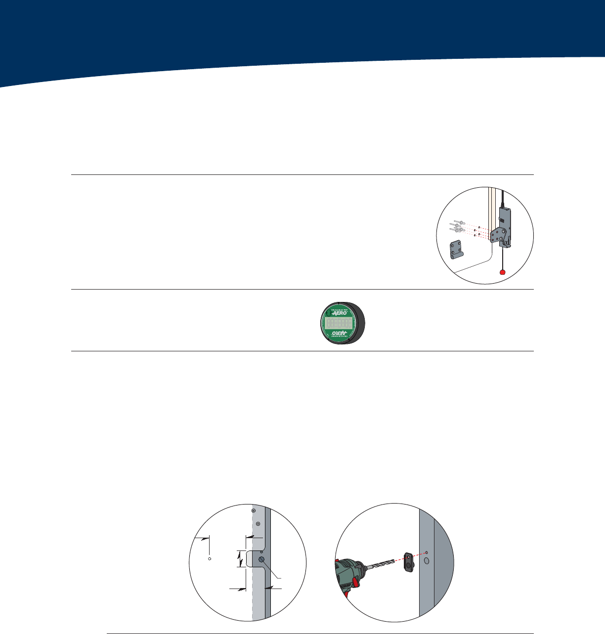
Attach Electronic Latches
Insert (4x) Ornit rivets from the outside of the Lateral Panel.
Rivet the electronic latch to the inside of the Lateral Panel.
Lateral Panel Grommet Cutout
Make a small 2" x 2" cutout where the latch cable will enter the trailer frame.
The cutout should be approximately 41" from the bottom of the TrailerTail.
The cutout may be moved up or down at most 6" to avoid a door hinge.
Drill a hole 4" horizontally from the grommet cutout with a 1/4" drill bit.
TrailerTails with custom cut lateral panels will have the grommet cutout and hole pre-drilled.
Drill Holes in Trailer Frame
Using a center punch, mark the trailer frame in the center of the 2" x 2" cutout and
centered horizontally on the frame. This mark will help keep the drill bit from wandering.
Drill a 5⁄8" hole in the frame. STEMCO recommends using a sheet metal hole saw.
Use a grommet bracket as a template to drill the rivet mounting hole for the bracket.
'RQRWULYHWJURPPHWEUDFNHWXQWLOVSHFLÀHG
Pre-Installation
STEMCO recommends installing the TrailerTail prior to installing the AutoDeploy® system.
1. Install TrailerTail
2. Latch Installation
AutoDeploy Installation
4"
2"
2"
ø⁄"
3. Install TracBAT RF® Aero™
Use TracBAT RF® install instructions found
in TracBAT box.
4. Panel & Trailer Preparation
AF
AF
AF
AF
AF
AF
AF
AF
AF
AF
AF
AF
DRAFT
05Install Manual – AutoDeploy®with TracBAT RF®|AutoDeploy Installation
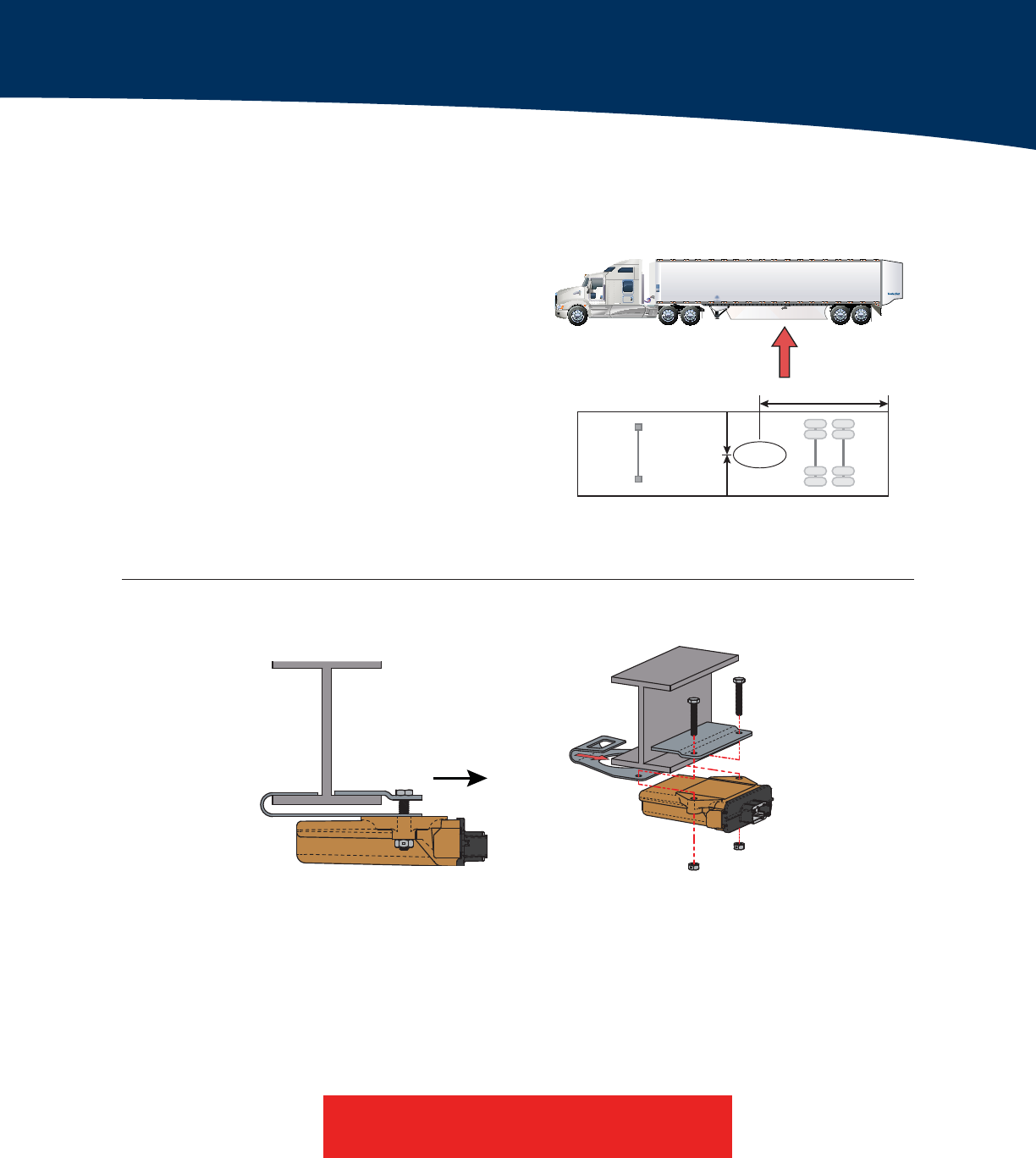
Use a tape measure to position the
TailBAT control unit. It should be
centered on the width of the trailer and
approximately 26 ft from the rear doors.
STEMCO recommends using the I-beam
located on or near the side marker lights.
You may need to move the TailBAT forward
or backward up to 2 ft to avoid I-beam
obstructions.
2. Align and Affix Bracket
Center the bracket on the width of the trailer.
Use the roll of the TailBAT base bracket to attach one side
of the bracket to an I-beam.
Place the clamp plate on the other side of the I-beam and
use the provided 1/4" bolts, washers and lock nuts to
secure the clamp plate, base bracket and TailBAT control
unit to the I-beam.
You may need to adjust the location to avoid possible obstructions.
1. Position TailBAT Control Unit
AutoDeploy Installation
TailBAT Control Unit
T
TailBAT
Control Unit
Front of
Trailer
Rear of
Trailer
Centered
on Width
26’
Connector
Towards Rear
Do not overtighten.
DRAFT
Customer Support | (888) 283-8245 x2 | ATDCustomerService@stemco.com06
AutoDeploy Installation
Warning Light Bracket
1. Position and Secure Warning Light Bracket
Position the light on the trailer’s front driver-side corner, 48" above the base of the trailer.
Match drill the 17/64" holes and rivet the bracket to the trailer using (4x) Ornit rivets.
48"
Jun
ction
Bo
x
®
ATD000743_E
®
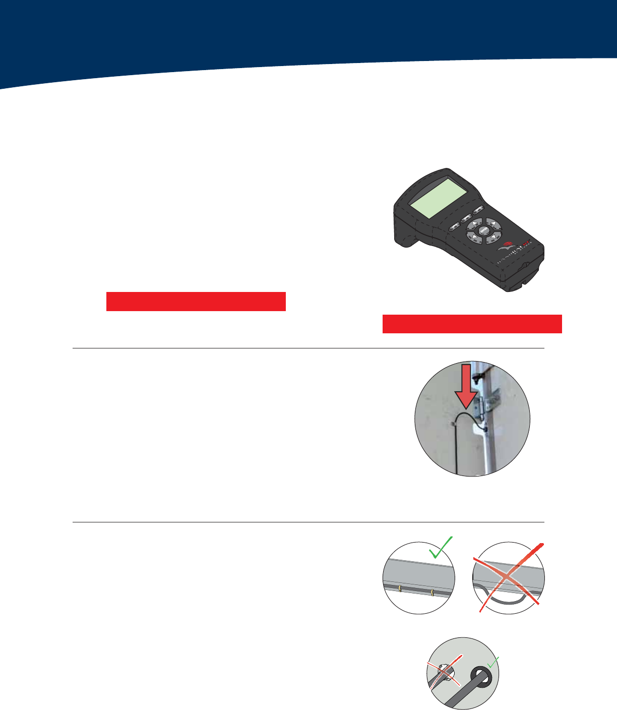
2. Route Warning Light Wire to Junction Box
Route the warning light wire to the junction box using up to 3 wire clamps.
The wire should be taught and not be able to vibrate or rub against other components.
Place the AutoDeploy Instruction Diagram decal on the front of the trailer in the bottom
right corner.
Secure the Warning Light
Route the Warning Light Wire
Riveted Wire Clamps
DRAFT
07Install Manual – AutoDeploy®with TracBAT RF®|AutoDeploy Installation
Main Wire Harness Routing to Front of Trailer
AutoDeploy Installation
1. Wire Routing
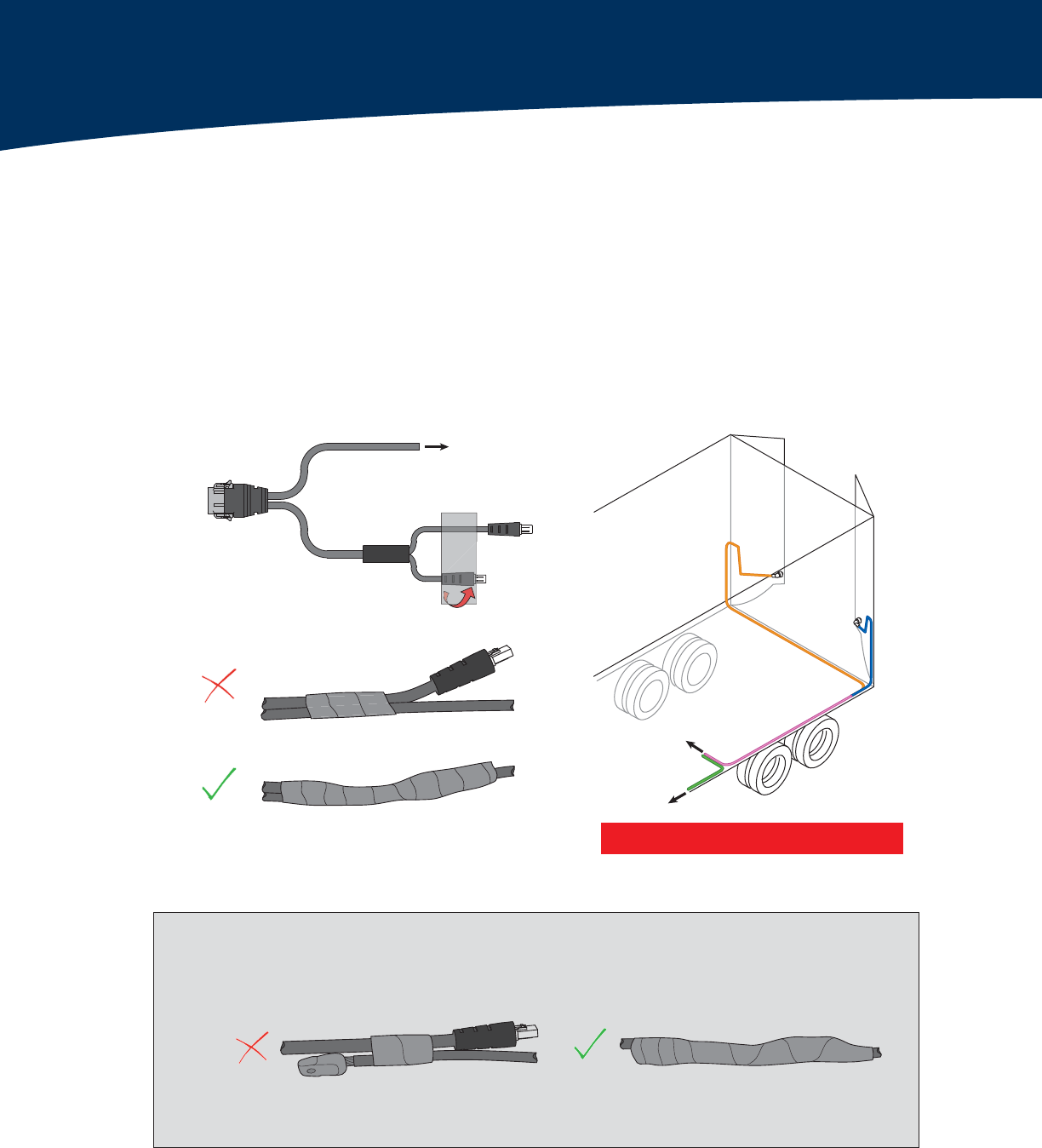
Plug in the 12-pin connector into the TailBAT control unit.
Route both the power cable (3-wire cable with no connector)
and the latch wires to the side of trailer and secure to I-beam.
Route only the power cable to the Junction Box at the front of
the trailer using an available underbody channel.
Use zip-ties along the underbody channel as needed to secure
the wires.
To TailBAT
Control Unit
To trailer harness
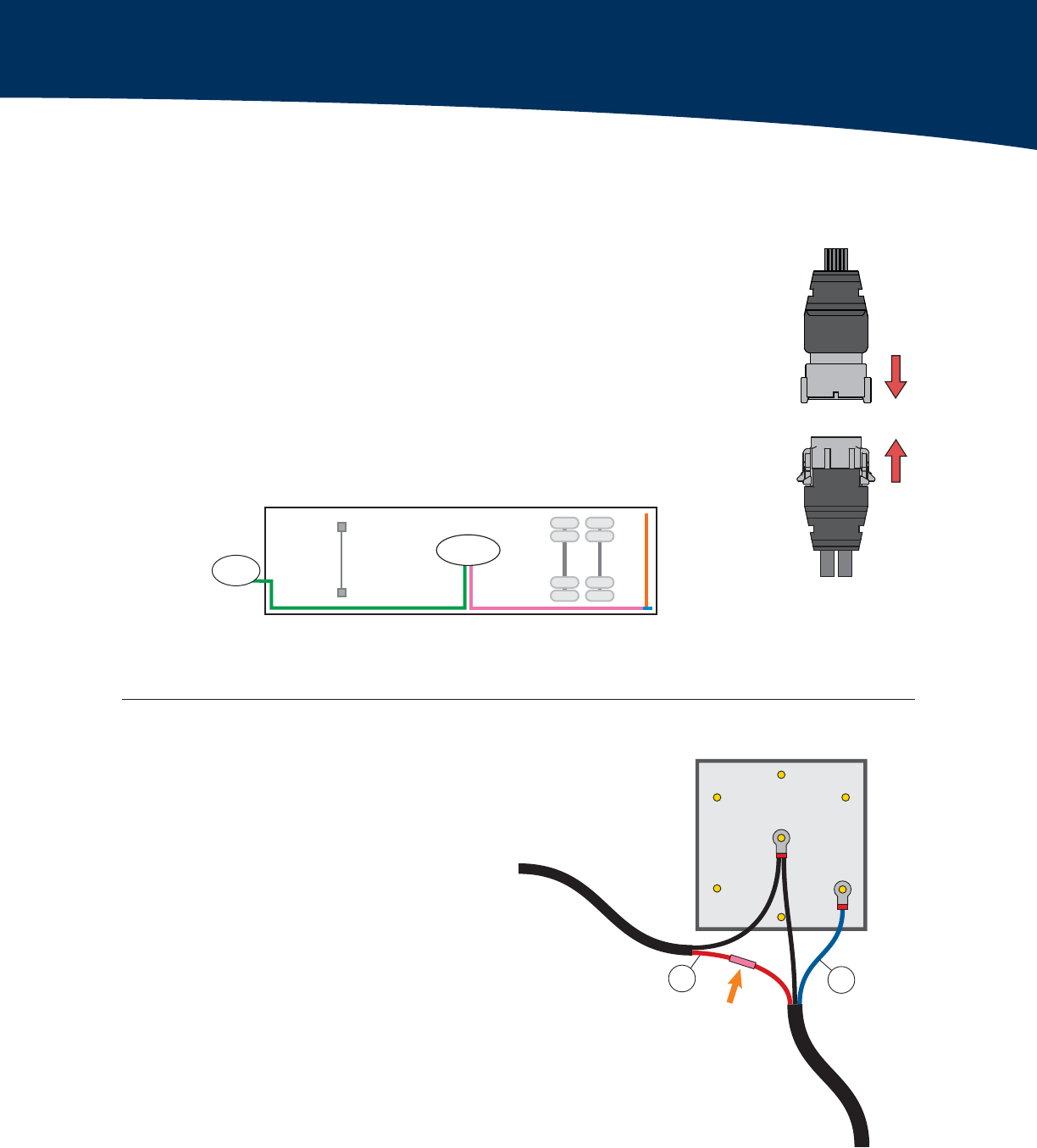
2. Junction Box Connections
Route power cable and warning light
wire into junction box.
Cut excess wire from both the warning
light wire and the power cable.
Approximately 8" of wire should remain for
completing connections.
Using a butt connector, connect the
red wire from the power cable to the
red wire of the warning light wire.
Terminate the blue and both black
wires with eye terminals.
Connect the blue wire to the
appropriate constant power pin.
Connect both black wires to the
ground terminal.
Close up access to the
junction box.
TailBAT
Control Unit
Junction
Box
Front of
Trailer
Rear of
Trailer
Curbside
Roadside
To Rear of Trailer
(Main Power)
Two-Wire
Light Cable
To Light
GND
J560 Rear Connections
PWR
(+12V)
Three-wire
Power Cable
Butt Connector
Light Power
Red Blue
Wire Harness Routing
DRAFT
Customer Support | (888) 283-8245 x2 | ATDCustomerService@stemco.com08
AutoDeploy Installation
Main Wire Harness Routing to Rear of Trailer
To Junction Box
A
A
A
A
A
A
A
INCORRECT
CORRECT
INCORRECT CORRECT
When using fish tape, secure the connector to the pulling cable.
To TailBAT
Control Unit
To Junction Box
1. Route Latch Connectors to Rear of Trailer
Route the latch wires to the rear of the trailer.
Tape the shorter latch wire to the longer latch wire.
Route the two latch connectors to the rear of the trailer along an underbody channel.
STEMCO Advice
Tape Connectors Securely Wire Harness Routing
Updated image
DRAFT
09Install Manual – AutoDeploy®with TracBAT RF®|AutoDeploy Installation
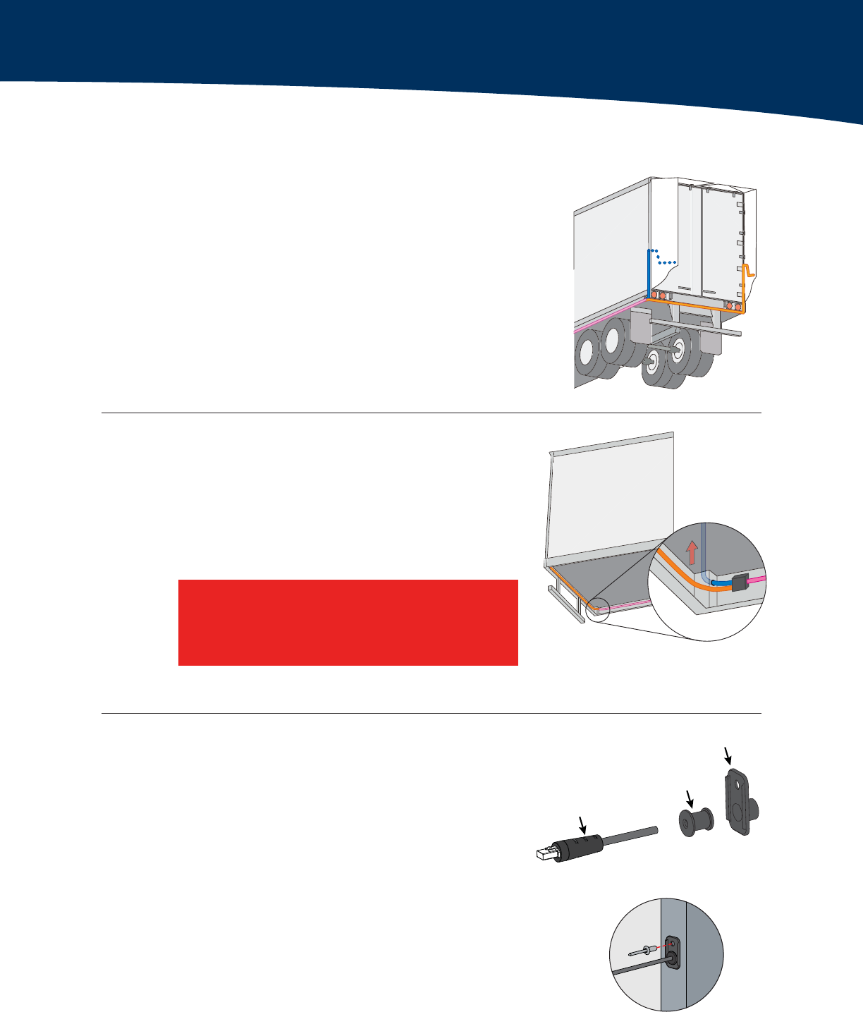
4. Assemble Grommet and
Grommet Bracket on Wire
Slide JST connector through back of plastic grommet
bracket.
Slide the grommet bracket so that approximately 3 ft of
wire is exposed.
Press the wire into the slit grommet. Push the
grommet into the grommet bracket until both lips of the
grommet sit flush against the grommet bracket.
7KHÀWPHQWRIWKHJURPPHWLVGHVLJQHGWREH
a tight seal.
Rivet the grommet bracket to the post.
2. Separate and Route Wires to Near and Far Side
Route the shorter latch wire to the near side of the trailer
and the longer latch wire to the far side.
Use zip-ties to secure the wires to the trailer frame.
FT
FT
T
T
T
T
T
T
T
T
T
T
T
T
T
T
T
T
T
T
T
T
T
T
T
FT
T
T
T
T
T
T
T
T
T
FT
FT
T
T
T
T
T
T
T
T
T
T
T
T
FT
FT
FT
T
FT
T
T
T
FT
T
T
FT
T
FT
FT
FT
T
T
FT
FT
FT
FT
FT
FT
FT
FT
FT
FT
FT
FT
FT
FT
FT
FT
FT
FT
FT
FT
FT
FT
FT
FT
FT
FT
FT
FT
FT
FT
FT
FT
FT
FT
FT
FT
FT
FT
FT
FT
FT
FT
FT
FT
FT
FT
FT
FT
FT
FT
FT
FT
FT
T
FT
FT
FT
FT
FT
FT
FT
FT
FT
T
FT
FT
FT
FT
FT
FT
FT
FT
FT
T
FT
T
T
T
T
FT
FT
FT
FT
FT
FT
FT
FT
FT
FT
FT
FT
FT
FT
FT
FT
FT
FT
FT
FT
FT
FT
FT
FT
FT
FT
FT
FT
FT
FT
T
T
T
T
T
T
T
T
T
T
T
T
FT
FT
FT
FT
FT
FT
FT
T
T
T
T
T
T
FT
FT
T
T
FT
T
T
FT
T
T
FT
T
T
T
T
T
T
T
T
T
T
T
T
FT
FT
T
T
FT
T
FT
JST Connector
Grommet
Grommet Bracket
AutoDeploy Installation
Main Wire Harness Routing to Rear of Trailer
Make sure wiring does not go through any
sharp or bare metal holes. Use grommets or
caulk to protect wire from bare metal.
A
A
A
AF
AF
A
AF
A
AF
A
AF
AF
AF
AF
AF
AF
AF
AF
A
A
A
A
A
A
A
A
A
A
A
A
AF
A
AF
A
AF
AF
A
A
AF
AF
3. Route Wire Up Through Frame Post
Send a nylon pulling rope from the 5⁄8" hole you drilled
earlier to the bottom of the post.
Use the nylon pulling rope to pull the latch cable through
the post. Make sure you do not tear the cable insulation
on any sharp corners. You may need to feed from the
bottom as you pull from the top.
Grommet Bracket Attachment
Grommet Bracket Assembly
DRAFT
FT
Customer Support | (888) 283-8245 x2 | ATDCustomerService@stemco.com10
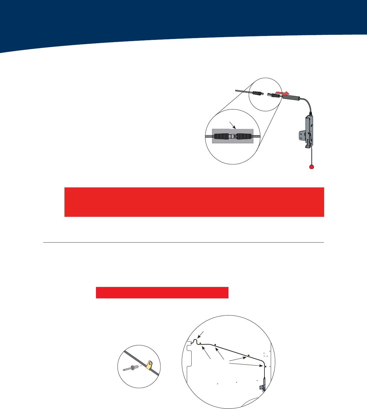
Wire Clamps
Slack for
door rotation
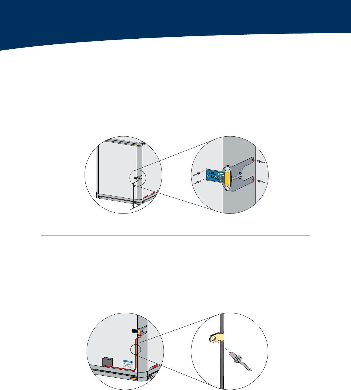
Main Wire Harness Routing on Lateral Panel
1. Connect Harness to Latches
Slide the heat shrink tubing over and past
the connector.
Plug the wire harness into the latch.
Slide heat shrink back over connector.
Evenly apply heat over the length of the
heat shrink tubing until it molds tightly to
the connector.
2. Attach Latch Wires to Panel
Place the wire clamps around the wire and rivet to the pre-drilled lateral panel holes to
secure the cable. Make sure the rivet enters from the wire clamp side.
If the holes are not pre-drilled, use a 17/64" drill bit to drill 3 holes approximately in the locations shown
below.
The cable between the clamps should be taut and not have room to move and damage itself,
except at the hinge joint between the panel and trailer frame.
If connector is damaged, replace latch wire. Do not use damaged connector.
See [ATD001905] Install Manual - AutoDeploy, Latch Wire Replacement.
FT
FT
FT
FT
Heat Shrink
AutoDeploy Installation
Riveted Wire Clamps
Harness to Latch Connection
Wiring Attached to Panel
Changed 1/4" to 17/64"
DRAFT
11Install Manual – AutoDeploy®with TracBAT RF®|AutoDeploy Installation
AF
AF
AF
AF
AF
AF
AF
AF
AF
AF
AF
AF
AF
AF
AF
AF
AF
AF
AF
AF
AF
AF
AF
AF
AF
AF
AF
AF
AF
AF
AF
AF
AF
AF
AF
AF
AF
AF
AF
AF
AF
AF
AF
AF
A
AF
AF
AF
AF
AF
AF
A
A
A
A
AF
A
AF
AF
AF
A
A
A
AF
AF
AF
AF
AF
AF
AF
AF
AF
AF
AF
AF
AF
AF
AF
AF
AF
AF
AF
AF
AF
AF
AF
AF
AF
AF
AF
AF
AF
AF
AF
AF
AF
AF
AF
AF
AF
AF
AF
AF
AF
AF
AF
AF
AF
AF
F
F
F
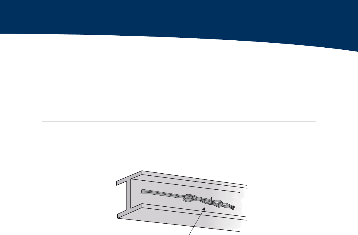
Bundle Excess Cable
4. Secure Wire Slack on Underside of Trailer
Secure any cable slack on the underside of the trailer. Zip-tie the cables in a loop behind the tail
lights inside the housing. Any movement can cause the wire jacket to wear and cause a short.
Main Wire Harness Routing on Lateral Panel
3. Open and Close TrailerTail to Test Wire Excess at Grommet
Leave approximately 3" of excess cable near the grommet. Test the excess by fully opening
the trailer door and checking for cable binding.
Feed excess wire into grommet, or pull extra wire out as needed.
AutoDeploy Installation
DRAFT
Customer Support | (888) 283-8245 x2 | ATDCustomerService@stemco.com12
3. Wiring - Trailer
Best Practices
All wire is tightly secured to the trailer and not capable
of sliding through clamps.
Wiring does not go through any sharp or bare metal holes.
Use grommets or caulk to protect wire from bare metal.
Wiring in J-Box is tight and not allowed to vibrate
against sharp edges.
This section outlines the components to inspect immediately after every AutoDeploy installation.
Post-Install Checklist
AutoDeploy® Post-Install Checklist
1. Electrical System Test
Test system by following the Electrical System Test on page
14.
If a HandBAT is not available perform the Limited System
Test on page 16.
If the system is not functional or if either test is
unsuccessful, refer to [ATD004122] AutoDeploy with
TracBAT, Field Service Manual to perform diagnostics.
The HandBAT® is available from STEMCO.
2. Wiring - Lateral Panel
There is enough slack in the wire at the area where the
wire enters the trailer frame to open the trailer door.
The wire should not be taut nor droop down by more than
a couple of inches when the door is latched to the side of
the trailer.
Wire Protected by
Grommet
Proper Wiring Slack
HandBAT®
Unsecured WiringSecured Wiring
Revised
Updated image and caption

DRAFT
13Install Manual – AutoDeploy®with TracBAT RF®|Post-Install Checklist
Post-Install Checklist
4. Heat Shrink Connections
Latch connector has heat shrink
uniformly applied.
AutoDeploy™ Post-Install Checklist
Uniform Heat Shrink
Application
DRAFT
Customer Support | (888) 283-8245 x2 | ATDCustomerService@stemco.com14
Electrical System Verification
AutoDeploy® Electrical System Verification
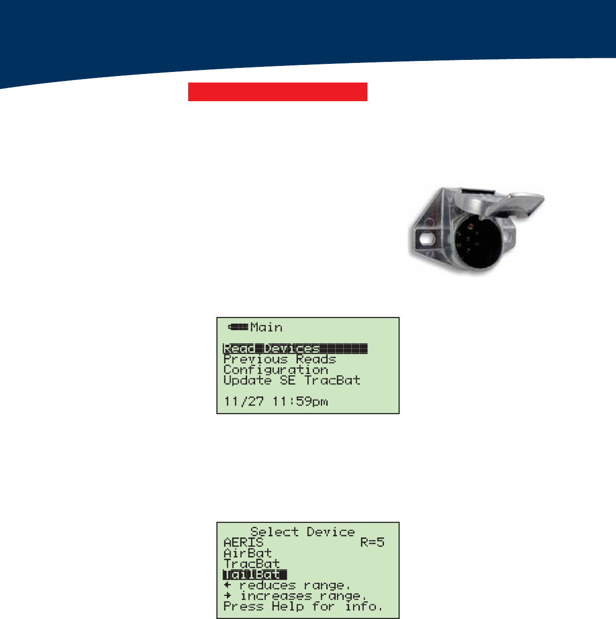
1. Plug-in Power
Plug power into the J-Box. AUX/blue line power is needed.
2. Main Menu
Select Read Devices
3. Select Device
Select TailBat
This section outlines a procedure to verify functionality of the Warning Light and
AutoDeploy components using the HandBAT.
Revised Section
The "R=5" indicates the signal range. If there are multiple AutoDeploy equipped TrailerTails in the vicinity, it
may be helpful to reduce the range to ensure proper communication with the desired device.
7KHLQGLFDWRUOLJKWRQWKH7DLO%$7ZLOOÁDVKEOXHWRVLJQDODFRPPXQLFDWLRQOLQNDIWHU(QWHULVSUHVVHG
DRAFT
15Install Manual – AutoDeploy®with TracBAT RF®|Post-Install Checklist
Electrical System Verification
AutoDeploy® Electrical System Verification
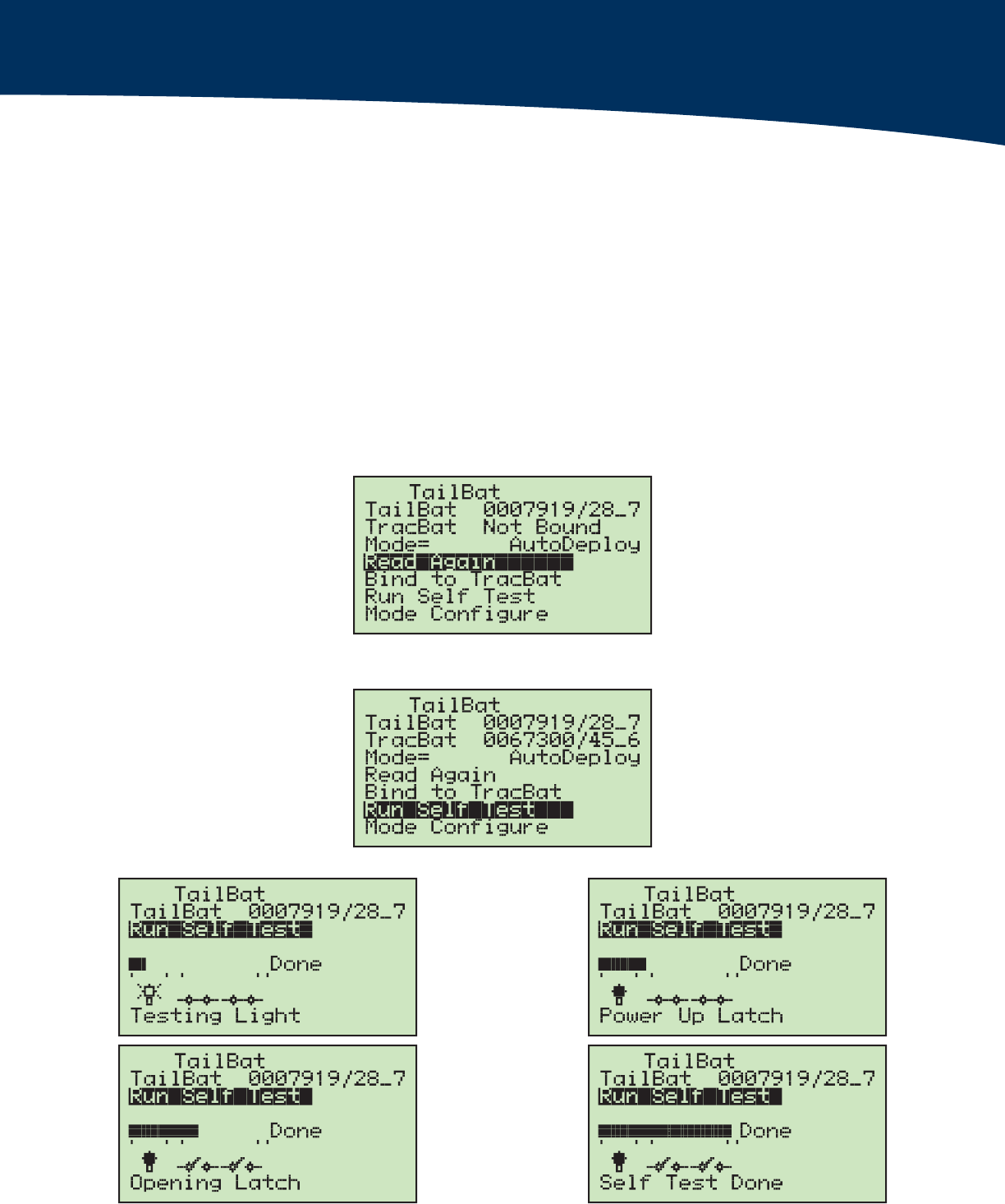
4. TracBat Not Bound
When you first read a new unit, it will read "TracBat Not Bound." This is normal — refer to
section XX "Binding Options" for more information.
Verify that the Mode is set to "AutoDeploy." If not, proceed to section XX to change the
mode and return to step 2.
If multiple TracBat devices are in range, pressing "Enter" when "Read Again" is highlighted
will randomly select a new TailBat to read.
5. Run Self Test
Select Run Self Test
The serial number shown on the screen will match the label on the TailBAT.
The following screens will appear upon successful latch testing.

DRAFT
Customer Support | (888) 283-8245 x2 | ATDCustomerService@stemco.com16
6. Self Test Complete
The HandBAT will show "No Problems Detected" upon successful completion of the test.
Verify the TrailerTail is open.

DRAFT
17Install Manual – AutoDeploy®with TracBAT RF®|Post-Install Checklist

DRAFT
Customer Support | (888) 283-8245 x2 | ATDCustomerService@stemco.com18
Spare Parts
Spare Parts List
Refer to the AutoDeploy & ZeroTouch Components section of the [ATD002975]
TrailerTail Spare Parts Catalog for a list of spare parts.

DRAFT
19Install Manual – AutoDeploy®with TracBAT RF®|Spare Parts
Certifications
Reference Material
FCC (USA)
This unit complies with Part 15 of the FCC Rules. Operation is subject to the following two
conditions: (1) this device may not cause harmful interference, and (2) this device must accept
any interference received, including interference that may cause undesired operation.
FCC ID: SRA-ATD003160
This equipment has been tested and found to comply with the limits for a Class B digital device,
pursuant to Part 15 of the FCC Rules. These limits are designed to provide reasonable protection
against harmful interference in a residential installation. This equipment generates uses and can
radiate radio frequency energy and, if not installed and used in accordance with the instructions,
may cause harmful interference to radio communications. However, there is no guarantee that
interference will not occur in a particular installation. If this equipment does cause harmful
interference to radio or television reception, which can be determined by turning the equipment off
and on, the user is encouraged to try to correct the interference by one or more of the following
measures:
„„ Reorient or relocate the receiving antenna.
„„ Increase the separation between the equipment and receiver.
„„ Connect the equipment into an outlet on a circuit different from that to which the receiver is
connected.
„„ Consult the dealer or an experienced radio/TV technician for help.
NOTE: The manufacturer is not responsible for any radio or TV interference caused by
unauthorized modifications to this equipment. Such modifications could void the user’s authority
to operate the equipment. The antenna(s) used for this transmitter must be installed to provide a
separation distance of at least 20 cm from all persons and must not be co-located or operating
in conjunction with any other antenna or transmitter. Users and installers must be provided with
antenna installation instructions and transmitter operating conditions for satisfying Rf exposure
compliance. Should you need any additional assistance with any problems or issues please contact
STEMCO Customer Service at (800) 527-8492.
Industry Canada
Contains/Contient IC: 7413A-ATD003160
NOTICE: This device complies with Industry Canada licence-exempt RSS standard(s). Operation is
subject to the following two conditions: (1) this device may not cause interference, and (2) this
device must accept any interference, including interference that may cause undesired operation of
the device.
vis: Cet appareil est conforme avec Industrie Canada RSS standard exempts de licence (s). Son
fonctionnement est soumis aux deux conditions suivantes: (1) cet appareil ne peut pas provoquer
d’interférences et (2) cet appareil doit accepter toute interférence, y compris les interférences qui
peuvent causer un mauvais fonctionnement du dispositif.

DRAFT
For more information visit www.stemco.com/trailertail or call 1-888-283-TAIL.
STEMCO USA — 300 Industrial Blvd. • Longview, Texas 75602 • (903) 758-9981 • 1-800-527-8492 • FAX 1-800-874-4297
STEMCO Mexico — Col. COLTONGO, Mèxico D.F • MEXICO C.P. 02630 • 011-52-53-68-26-37
STEMCO Canada — 5775 McLaughlin Road • Mississauga, ON L5R 3P7 • (905) 206-9922 • (877) 232-9111 • FAX (877) 244-4555
Printed in U.S.A. ISO 16949 STEMCO and TrailerTail are trademarks of STEMCO LP. © 2017 Part Number: ATD004078 2/18