Stihl Fs75 Manual FS 75
2014-07-06
: Stihl Fs75-Manual fs75-manual stihl pdf
Open the PDF directly: View PDF ![]() .
.
Page Count: 78
- Contents
- Guide to Using this Manual
- Safety Precautions and Working Techniques
- Mounting the Loop Handle
- Fitting the Carrying Eye*
- Mounting the Deflector
- Mounting the Cutting Tools
- Fuel
- Fueling
- Fitting the Harness
- Starting / Stopping the Engine
- Operating Instructions
- Cleaning the Air Filter
- Motor Management
- Adjusting the Carburetor
- Spark Arresting Screen* in Muffler
- Checking the Spark Plug
- Replacing the Starter Rope and Rewind Spring
- Storing the Machine
- Replacing Nylon Line
- Maintenance Chart
- Parts and Controls
- Specifications
- Special Accessories
- Maintenance and Repairs
- STIHL Incorporated Federal and California Emission Control Warranty Statement
Instruction Manual
Manual de instrucciones
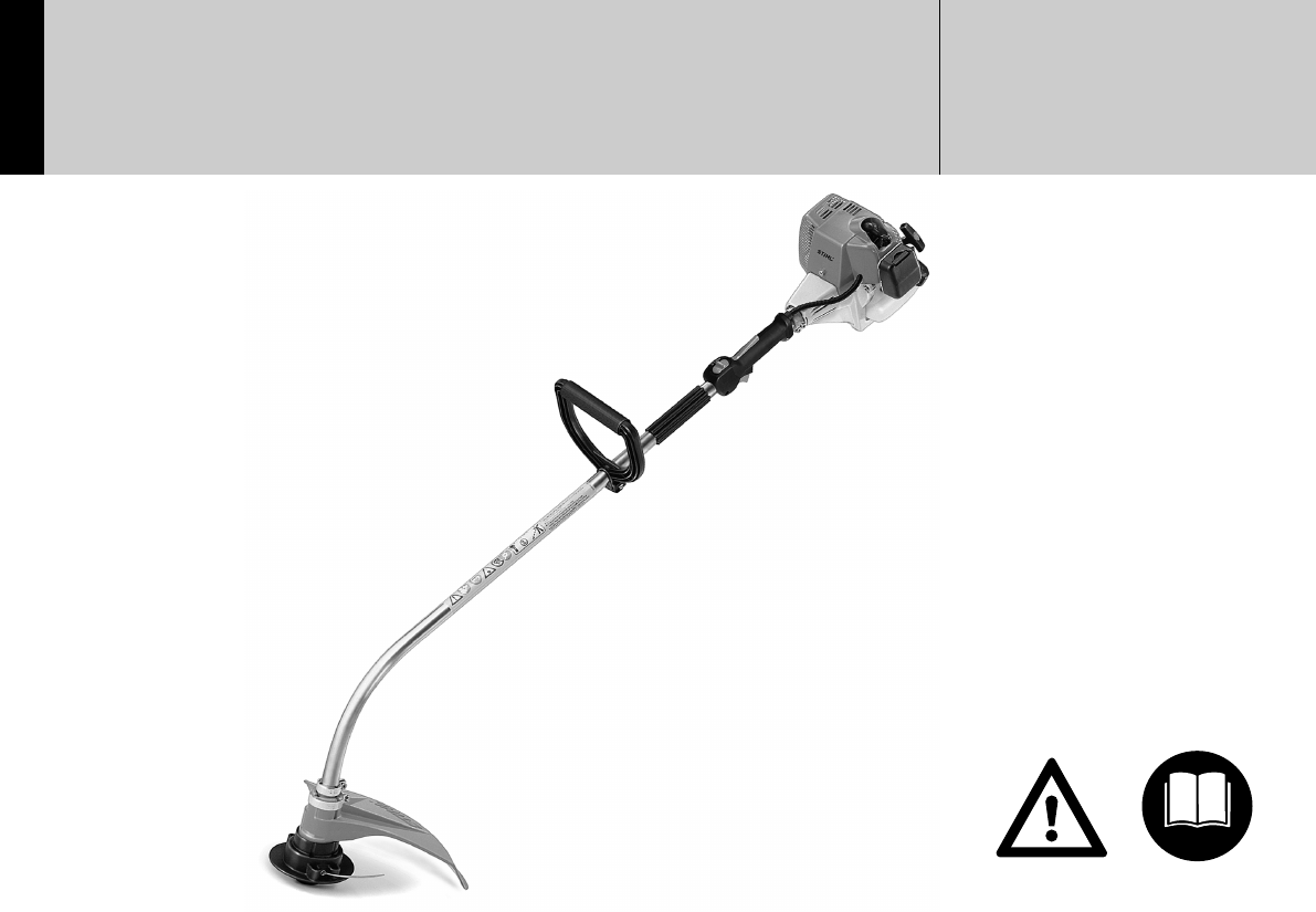
Warning!
For safe operation follow all safety
precautions in Instruction Manual - improper
use can cause serious injury.
Advertencia!
Para su seguridad durante el manejo de este
producto, siga siempre las precauciones de
seguridad dadas en el manual de
instrucciones - el uso indebido puede causar
lesiones graves.
STIH)
STIHL FS 75
BA_FS75_30_U_A4.book Seite 0 Dienstag, 20. Januar 2004 8:54 08
1FS 75
English / USA
BA_SE_068_007_01_04.fm Printed on chlorine-free paper.
Printing inks contain vegetable oils; paper can be recycled.
© ANDREAS STIHL AG & Co. KG, 2004
0458 392 3021. M3. A4. PM. Printed in USA
STIHl
Contents
Guide to Using this Manual .............. 2
Safety Precautions and
Working Techniques ......................... 3
Mounting the Loop Handle ............. 14
Fitting the Carrying Eye* ................ 15
Mounting the Deflector ................... 15
Mounting the Cutting Tools ............. 15
Fuel ................................................ 18
Fueling ............................................ 19
Fitting the Harness ......................... 20
Starting / Stopping the Engine ........ 20
Operating Instructions .................... 23
Cleaning the Air Filter ..................... 23
Motor Management ........................ 24
Adjusting the Carburetor ................ 24
Spark Arresting Screen*
in Muffler ......................................... 26
Checking the Spark Plug ................ 26
Replacing the Starter Rope
and Rewind Spring ......................... 27
Storing the Machine ........................ 30
Replacing Nylon Line ..................... 30
Maintenance Chart ......................... 32
Parts and Controls .......................... 33
Specifications ................................. 35
Special Accessories ....................... 36
Maintenance and Repairs ............... 36
STIHL Incorporated Federal
and California Emission Control
Warranty Statement ........................ 37
* see “Guide to Using this Manual”
Allow only persons who understand this
manual to operate your trimmer.
To receive maximum performance and
satisfaction from your STIHL trimmer, it
is important that you read and under-
stand the maintenance and safety
precautions, starting on page 3, before
using your trimmer.
Contact your STIHL dealer or the STIHL
distributor for your area if you do not
understand any of the instructions in this
manual.
!Warning!
Because a trimmer is a high-speed
cutting tool some special safety pre-
cautions must be observed to reduce
the risk of personal injury.
Careless or improper use may cause
serious or even fatal injury. Make sure
your unit is equipped with the proper
deflector, handle and harness for the
type of cutting attachment being used.
Always wear proper eye protection.
STIHL's philosophy is to continually
improve all of its products. As a result,
engineering changes and improve-
ments are made from time to time. If the
operating characteristics or the appear-
ance of your trimmer differs from those
described in this manual, please contact
your STIHL dealer for information and
assistance.

2
English / USA
FS 75
Pictograms
All the pictograms attached to the
machine are shown and explained in
this manual.
The operating and handling instructions
are supported by illustrations.
Symbols in text
The individual steps or procedures
described in the manual may be marked
in different ways:
:Step or procedure without direct
reference to an illustration.
Description of step or procedure that
refers directly to the illustration and
contains item numbers that appear in
the illustration.
Example:
Loosen the screw (1)
Lever (2) ...
In addition to the operating instructions,
this manual may contain paragraphs
that require your special attention. Such
paragraphs are marked with the
symbols described below:
Warning where there is a risk of an
accident or personal injury or
serious damage to property.
Warning where there is a risk of
damaging the machine or individual
components.
Note or hint which is not essential
for using the machine, but may
improve the operator’s under-
standing of the situation and result
in better use of the machine.
Note or hint on correct procedure in
order to avoid damage to the
environment.
Equipment and features
This instruction manual refers to
several models with different
features. Components that are not
installed in all models and related
applications are marked thus *.
Such components are available as
special accessories from your
STIHL dealer.
Engineering improvements
STIHL’s philosophy is to continually
improve all of its products. As a result,
engineering changes and improvements
are made from time to time. If the
operating characteristics or the
appearance of your machine differ from
those described in this manual, please
contact your STIHL dealer for
assistance.
Therefore, we cannot be responsible for
changes, modifications or
improvements not covered in this
manual.
Guide to Using this Manual

3FS 75
English / USA
Warning!
Because a trimmer is a
high-speed, fast-cutting
power tool, special safety
precautions must be
observed to reduce the
risk of personal injury.
It is important that you
read, fully understand and
observe the following
safety precautions and
warnings. Read the
owner's manual and the
safety instructions periodically.
Careless or improper use of any trimmer
may cause serious or fatal injury.
Have your STIHL dealer show you how
to operate your trimmer. Observe all
applicable local safety regulations,
standards and ordinances.
!Warning!
Do not lend or rent your trimmer without
the owner's manual. Be sure that any-
one using your trimmer understands the
information contained in this manual.
!Warning!
The use of any trimmer may be
hazardous. If the rotating cutting tool
comes in contact with your body, it will
cut you. When it comes in contact with
solid foreign objects such as rocks or
bits of metal, it may fling them directly or
by ricochet in the direction of bystanders
or the operator. Striking such objects
could damage the cutting tool. Thrown
objects or damaged cutting tools may
result in serious or fatal injury to the
operator or bystanders.
!Warning!
Minors should never be allowed to
use a trimmer. Bystanders, especially
children, and animals should not be
allowed in the area where a trimmer
is in use.
Never let the trimmer run unattended.
Most of these safety precautions and
warnings apply to the use of all STIHL
trimmers. Different models may have
different parts and controls. See the
appropriate section of your owner's
manual for a description of the controls
and function of the parts of your model
trimmer.
Safe use of a trimmer involves
1. the operator
2. the trimmer
3. the use of the trimmer.
THE OPERATOR!
Physical Condition
You must be in good physical condition
and mental health and not under the
influence of any substance (drugs,
alcohol, etc.) which might impair vision,
dexterity or judgement. Do not operate a
trimmer when you are fatigued.
Be alert - if you get tired while operating
your trimmer, take a break.
Tiredness may result in loss of control.
Working with any trimmer can be
strenuous. If you have any condition that
might be aggravated by strenuous work,
check with your doctor before operating
a trimmer.
Safety Precautions and
Working Techniques

4
English / USA
FS 75
!Warning!
Prolonged use of a trimmer (or other
machines) exposing the operator to
vibrations may produce whitefinger
disease (Raynaud's phenomenon) or
carpal tunnel syndrome.
These conditions reduce the hand's
ability to feel and regulate temperature,
produce numbness and burning
sensations and may cause nerve and
circulation damage and tissue necrosis.
All factors which contribute to white-
finger disease are not known, but cold
weather, smoking and diseases or
physical conditions that affect blood
vessels and blood transport, as well as
high vibration levels and long periods of
exposure to vibration are mentioned as
factors in the development of whitefinger
disease. In order to reduce the risk of
whitefinger disease and carpal tunnel
syndrome, please note the following:
:Most STIHL power tools are
available with an anti-vibration
("AV") system designed to reduce
the transmission of vibrations
created by the engine to the
operator's hands. An AV system is
recommended for those persons
using power tools on a regular or
sustained basis.
:Wear gloves and keep your hands
warm.
:Keep the AV system well
maintained. A trimmer with loose
components or with damaged or
worn AV buffers will tend to have
higher vibration levels.
:Maintain a firm grip at all times, but
do not squeeze the handles with
constant, excessive pressures and
take frequent breaks.
All the above mentioned precautions do
not guarantee that you will not sustain
whitefinger disease or carpal tunnel
syndrome. Therefore continual and
regular users should monitor closely the
condition of their hands and fingers. If
any of the above symptoms appear,
seek medical advice immediately.
!Warning!
The ignition system of the STIHL unit
produces an electromagnetic field of a
very low intensity. This field may
interfere with some pacemakers. To
reduce the risk of serious or fatal injury,
persons with pacemaker should consult
their physician and the pacemaker
manufacturer before operating this tool.
Proper Clothing
!Warning!
To reduce the risk of injury, the operator
should wear proper protective apparel.
!Warning!
The deflector provided with your trimmer
may not protect the operator from all
foreign objects (gravel, glass, wire, etc.)
thrown by the rotating cutting tool.
Thrown objects may also ricochet and
strike the operator.
!Warning!
To reduce the risk of injury
to your eyes never
operate a trimmer unless
wearing goggles or
properly fitted safety
glasses with adequate top
and side protection complying with ANSI
Z 87.1 (or your applicable national
standard).
To reduce the risk of injury to your face
STIHL recommends that you also wear
a face shield or face screen over your
goggles or safety glasses.

5FS 75
English / USA
!Warning!
Trimmer noise may
damage your hearing.
Wear sound barriers
(ear plugs or ear mufflers)
to protect your hearing.
Continual and regular
users should have their hearing checked
regularly.
Protect your hands with
gloves when handling the
trimmer and the cutting
tool. Heavy-duty, nonslip
gloves improve your grip
and protect your hands.
Clothing must be sturdy
and snug-fitting, but allow
complete freedom of
movement. Avoid loose-
fitting jackets, scarfs,
neckties, jewelry, flared or
cuffed pants, unconfined longhair or
anything that could become caught on
branches, brush or moving parts of the
unit. Wear long pants made of heavy
material to protect your legs. Do not
wear shorts, pants, sandals or go bare
foot. Secure hair so it is above shoulder
level.
Good footing is most
important in trimmer work.
Wear sturdy boots with
nonslip soles. Steel-toed
safety boots are
recommended.
Wear an approved safety
hard hat to reduce the risk
of injury to your head
when there is a danger of
head injuries.
THE TRIMMER
For illustrations and definitions of the
trimmer parts see the chapter on "Parts
and Controls".
!Warning!
Never modify a trimmer in any way. Only
attachments supplied by STIHL or
expressly approved by STIHL for use
with the specific STIHL trimmer models
are authorized. Although certain
unauthorized attachments are useable
for the STIHL trimmer, their use may, in
fact, be extremely dangerous.
!Warning!
To reduce the risk of injury to operator
from blade contact, metal blades may be
used on FS-trimmers equipped with a
bicycle, "J" handle or loop handle with
barrier bar and not on those FS- and
FE-models with a loop handle only.
Never use any
metal cutting
attachment on a
FS-model that has
a bent shaft.
6
English / USA
FS 75
THE USE OF THE TRIMMER
Transporting the trimmer
!Warning!
Always turn off the engine and make
sure the cutting attachment has stop-
ped before putting a trimmer down.
When transporting your trimmer in a
vehicle, properly secure it to prevent
turnover, fuel spillage and damage to the
trimmer.
Preparation for the use of the trimmer
Adjust hand grip according to
instructions in the owner's manual to suit
your size before starting work.
Always check your trimmer for proper
condition and operation before starting,
particularly the throttle trigger, throttle
trigger interlock (if applicable), stop
switch, cutting tool, and deflector.
Arrows on the deflector show the correct
direction of rotation of the cutting tool.
The throttle trigger must move freely
and always spring back to the idle
position. The cutting tool must be
properly tightened and in safe operating
condition. Inspect for loose parts (nuts,
screws, etc.).
Fueling
Your STIHL trimmer uses an oil-gasoline
mixture for fuel (see the chapter on
"Fuel" of your owner's manual).
!Warning!
Gasoline is an extremely
flammable fuel. If spilled
and ignited by a spark or
other ignition source, it
can cause fire and serious
burn injury or property
damage. Use extreme caution when
handling gasoline or fuel mix.
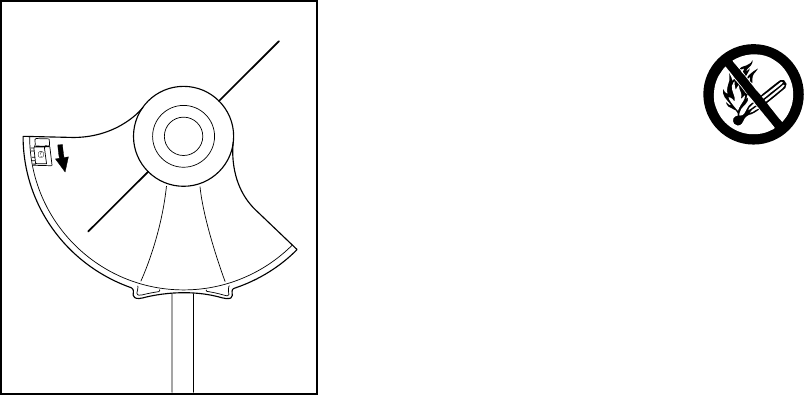
Do not smoke or bring any fire or flame
near the fuel or trimmer.
Fueling Instructions
!Warning!
Fuel your trimmer in well-ventilated
areas, outdoors. Always shut off the
engine and allow it to cool before
refueling. Gasoline vapor pressure may
build up inside the gas tank depending
on the fuel used, the weather conditions,
and the venting system of the tank. In
order to reduce the risk of burns and
other personal injury from escaping gas
vapor and fumes, remove the fuel filler
cap on your trimmer carefully so as to
allow any pressure build-up in the tank
to release slowly. Never remove fuel
filler cap while engine is running.
234BA004KN
7FS 75
English / USA
Select bare ground for fueling and move
at least 10 feet (3 m) from the fueling
spot before starting the engine. Wipe off
any spilled fuel before starting your
trimmer and check for leakage.
!Warning!
Check for fuel leakage while refueling
and during operation. If fuel or oil
leakage is found, do not start or run the
engine until leak is fixed and spilled fuel
has been wiped away. Take care not to
get fuel on your clothing. If this happens,
change your clothing immediately.
Different models may be equipped with
different fuel caps.
Cap with Grip
!Warning!
In order to reduce the risk of fuel spillage
and fire from an improperly tightened
fuel cap, correctly position and tighten
the fuel cap in the fuel tank opening.
To do this with this STIHL
cap, raise the grip on the
top of the cap until it is
upright at a 90° angle.
Insert the cap in the fuel
tank opening with the
triangular marks on the grip of the cap
and on the fuel tank opening lining up.
Using the grip, turn the cap firmly
clockwise as far as it will go (approx. a
quarter turn).
Fold the grip flush with the
top of the cap. If the grip
does not lie completely
flush with the cap and the
detent on the grip does
not fit in the
corresponding recess in the filler neck,
the cap is not properly seated and
tightened and you must repeat the
above steps.
Screw Cap
!Warning!
Unit vibrations can cause
an improperly tightened
fuel filler cap to loosen or
come off and spill
quantities of fuel.
In order to reduce the risk
of fuel spillage and fire, tighten the fuel
filler cap by hand with as much force as
possible.
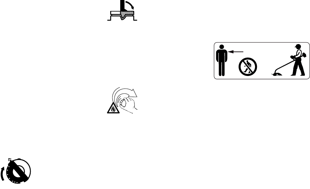
Starting
!Warning!
Your trimmer is a one-person machine.
Once started, it may fling foreign objects
for a great distance.
To reduce the risk of eye and other injury
insure that bystanders are at least
50 feet (15 m) away. Bystanders should
be encouraged to wear eye protection.
Stop the engine and cutting tool
immediately if you are approached. Start
and operate your trimmer without
assistance. For specific starting
instructions, see the appropriate section
of your manual. Place the trimmer on
firm ground or other solid surface in an
open area. Maintain a good balance and
secure footing.
15m (50ft)

8
English / USA
FS 75
!Warning!
To reduce the risk of injury from loss
of control, be absolutely sure that the
cutting tool is clear of you and all other
obstructions and objects, including the
ground, because when the engine starts
at starting-throttle, engine speed will be
fast enough for the clutch to engage and
turn the cutting tool.
!Warning!
When you pull the starter grip, don't
wrap the starter rope around your hand.
Do not allow the grip to snap back, but
guide the starter rope to rewind it
properly. Failure to follow this procedure
may result in injury to hand or fingers
and may damage the starter
mechanism.
With the engine running but at idle,
attach the trimmer to the spring hook of
your harness (see appropriate chapter
of this manual).
Catalytic converter
!Warning!
Some STIHL trimmer
models are equipped with
a catalytic converter,
which is designed to
reduce the exhaust
emissions of the engine
by a chemical process in the muffler.
Due to this process, the muffler does not
cool down as rapidly as conventional
mufflers when the engine returns to idle
or is shut off. To reduce the risk of fire
and burn injuries, the following specific
safety precautions must be observed.
!Warning!
Since a muffler with a catalytic converter
cools down less rapidly than conven-
tional mufflers, always set your trimmer
down in the upright position and never
locate it where the muffler is near dry
brush, grass, wood chips or other
combustible materials while it is still hot.
Let the engine cool down sitting on
concrete, metal, bare ground or solid
wood (e.g. the trunk of a felled tree)
away from any combustible substances.
!Warning!
To reduce the risk of fire or burn injury,
let the unit cool down before refueling
your trimmer after use.
!Warning!
Never disassemble or modify your
muffler. The muffler could be damaged
and cause an increase in heat radiation
or sparks, thereby increasing the risk of
fire or burn injury. You may also
permanently damage the engine. Have
your muffler serviced and repaired by
your STIHL Servicing Dealer only.
!Warning!
To reduce the risk of fire or burn injury,
keep the area around the muffler clean.
Remove all debris such as pine needles,
branches or leaves.

9FS 75
English / USA
!Warning!
An improperly mounted or damaged
cylinder housing or a damaged/
deformed muffler shell may interfere
with the cooling effect of the catalytic
converter. To reduce the risk of fire or
burn injury, do not continue work with a
damaged or improperly mounted
cylinder housing or a damaged/
deformed muffler shell. Your catalytic
converter is furnished with screens
designed to reduce the risk of fire from
the emission of hot particles. Due to the
heat from the catalytic reaction, these
screens will normally stay clean and
need no service or maintenance. If you
experience loss of performance and you
suspect a clogged screen, have your
muffler maintained by a STIHL Servicing
Dealer.
Working Conditions
Operate and start your trimmer only
outdoors in a ventilated area. Operate
the trimmer under good visibility and
daylight conditions only. Work carefully.
!Warning!
Your trimmer produces
toxic exhaust fumes as
soon as the engine is
running. These gases
(e.g. carbon monoxide)
may be colorless and
odorless. To reduce the risk of serious or
fatal injury from inhaling toxic fumes,
never run the trimmer indoors or in
poorly ventilated locations.
!Warning!
Use of this product can generate dust
and fumes containing chemicals known
to cause respiratory disease, cancer,
birth defects, or other reproductive
harm. If you are unfamiliar with the risks
associated with the particular dust or
fume at issue, consult your employer,
governmental agencies such as OSHA
and NIOSH, and other sources on
hazardous materials. California and
some other authorities, for instance,
have published lists of substances
known to cause cancer, reproductive
toxicity, etc. Control dust and fumes at
the source where possible. In this regard
use good work practices and follow the
recommendations of OSHA/NIOSH and
occupational and trade associations.
When the inhalation of toxic dust and
fumes cannot be eliminated, the
operator and any bystanders should
always wear a respirator approved by
NIOSH / MSHA for the type of dust and
/ or fumes encountered."
!Warning!
The muffler and other parts of the engine
(e.g. fins of the cylinder, spark plug)
become hot during operation and remain
hot for a while after stopping the engine.
To reduce risk of burns do not touch the
muffler and other parts while they are
hot.
Do not cut any material other than
weed or similar soft vegetation.
The cutting tools may be used only
for the operations described in your
manual.
10
English / USA
FS 75
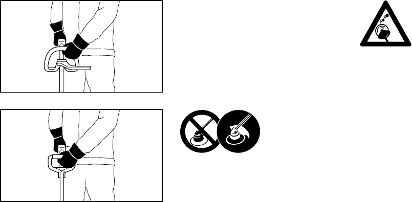
Always hold the trimmer firmly with both
hands. Wrap your fingers tightly around
the handles, keeping the handles
cradled between your thumb and fore-
finger. Keep your hands in this position
to have your trimmer under control at all
times. Make sure your trimmer handles
and grip are in good condition and free
of moisture, pitch, oil or grease.
!Warning!
Never attempt to operate any trimmer
with one hand. Loss of control of the
trimmer resulting in serious or fatal injury
may result.
!Warning!
To reduce the risk of bodily injury
resulting from loss of control and/or
contact with the cutting tool, make sure
your unit is equipped with the proper
handle and harness for the type of
cutting attachment being used.
!Warning!
To reduce the risk
of injury from
thrown objects and
blade contact,
never operate a
trimmer without a properly mounted
deflector. Keep the deflector (and the
skirt where appropriate) adjusted
properly at all times (see chapter on
mounting the various cutting tools of
your owner's manual). Do not
overreach. Keep proper footing and
balance at all times. Special care must
be taken in slippery conditions (wet
ground, snow) and in difficult, overgrown
terrain. Watch for hidden obstacles such
as tree stumps, roots and ditches to
avoid stumbling. Be extremely cautious
when working on slopes or uneven
ground.
Before cutting, inspect the
area for stones, glass,
pieces of metal, trash or
other solid objects. The
cutting attachment could
throw objects of this kind.
!Warning!
This trimmer is normally to be used at
ground level with the cutting attachment
parallel to the ground. Use of a trimmer
above ground level or with the cutting
attachment perpendicular to the ground
may increase the risk of injury, since the
cutting attachment is more fully exposed
and the trimmer may be more difficult to
control. Never use your trimmer as a
hedge trimmer.
Do not operate using the starting
throttle lock as you do not have control
of the engine speed. See section of your
owner's manual on the proper use of the
slide control.
If the cutting tool or deflector becomes
clogged or stuck, always turn off the
engine and make sure the cutting tool
has stopped, before cleaning. Grass,
weeds, etc. should be cleaned off the
cutting tool at regular intervals.
002BA057 KN002BA056 KN

11FS 75
English / USA
!Warning!
During cutting, check the tightness and
the condition of the cutting tool at
regular intervals. If the behavior of the
tool changes, stop the engine im-
mediately, and check the nut securing
the tool for tightness and the cutting
tool for cracks and damage. Replace
damaged cutting tools immediately.
Such tools may shatter at high speed
and cause serious or fatal injury.
!Warning!
Keep hands and feet
away from cutting tool.
Never touch a rotating
cutting tool with your hand
or any part of your body. It
continues to rotate for a
short period after the throttle trigger is
released (flywheel effect).
Important adjustments
!Warning!
To reduce the risk of personal injury from
loss of control or contact with the
running cutting tool, do not use a cutting
tool with incorrect idle adjustment.
At correct idle speed, the cutting tool
should not move. For directions on how
to adjust idle speed, see the appropriate
section of your owner's manual.
If you cannot set the correct idle speed,
have your STIHL dealer check your
trimmer and make proper adjustments
and repairs.
MAINTENANCE, REPAIR AND
STORING
Maintenance, replacement, or repair
of the emission control devices and
systems may be performed by any
nonroad engine repair establishment
or individual. However if you claim
warranty for a component which has
not been serviced or maintained
properly or if non-approved replace-
ment parts were used, STIHL may
deny warranty.
!Warning!
Use only STIHL replacement parts for
maintenance and repair.
Use of non-STIHL parts may cause
serious or fatal injury.
Follow the maintenance and repair
instructions in the appropriate section of
your owner's manual. Please refer to the
maintenance chart on the last pages of
this manual.
!Warning!
Always stop the engine and make sure
that the cutting tool is stopped before
doing any maintenance or repair work
or cleaning the trimmer. Do not attempt
any maintenance or repair work not
described in your owner's manual.
Have such work performed at your
STIHL service shop only.
12
English / USA
FS 75
!Warning!
Never repair damaged cutting tools by
welding, straightening or modifying the
shape. This may cause parts of the
cutting tool to come off and result in
serious or fatal injuries.
!Warning!
Check condition of cutting tool at regular
short intervals. If behavior of tool
changes, check it immediately for
tightness or any signs of cracks in
particular. Replace damaged or dull
cutting tools immediately, even if they
have only superficial cracks. If the
tool loosens after being properly
tightened, the retaining nut may be
worn or damaged and should be
replaced. If the tool continues to loosen,
see your STIHL dealer.
!Warning!
To reduce the risk of fire and burn
injuries, check fuel filler cap for leaks at
regular intervals. Use the specified
spark plug and make sure it and the
ignition lead are always clean and in
good condition.
!Warning!
Never test the ignition system with
ignition wire terminal removed from
spark plug or with unseated spark plug,
since uncontained sparking may cause
a fire.
!Warning!
To reduce the risk of fire and burn injury,
use only spark plugs authorized by
STIHL. Always press spark plug boot
snugly onto spark plug terminal of the
proper size. (Note: If terminal has
detachable SAE adapter nut, it must be
attached.) A loose connection between
spark plug terminal and ignition wire
connector in the boot may create arcing
that could ignite combustible fumes and
cause a fire. Keep spark plug clean, and
make sure ignition lead is in good
condition.
!Warning!
Do not operate your trimmer if the
muffler is damaged, missing or modified.
An improperly maintained muffler will
increase the risk of fire and hearing loss.
Never touch a hot muffler or burn will
result. If your muffler was equipped with
a spark-arresting screen to reduce the
risk of fire, never operate your trimmer if
the screen is missing or damaged. Do
not modify or remove any part of the
muffler or spark arresting screen.
Remember that the risk of forest fires is
greater in hot or dry weather.
Tighten all nuts, bolts and screws,
except the carburetor adjustment
screws, after each use.
Additionally, the daily maintenance
schedule for your trimmer set forth in
your STIHL Owner's Manual should be
strictly followed.
For any maintenance please refer to the
maintenance chart and to the warranty
statement near the end of this manual.
Store trimmer in a dry, high or locked
location out of reach of children.
Before storing for longer than a few
days, always empty the fuel tank.

13FS 75
English / USA
USING THE CUTTING TOOLS
For an illustration of the various cutting
tools and instructions on proper mount-
ing see the chapter on "mounting the
cutting head" in your owner's manual.
Using the mowing heads
The STIHL AutoCut and PolyCut
mowing heads produce a clean and tidy
finish.
They are to be used only on trimmers
equipped with a limiter blade in the
deflector in order to keep the line at the
proper length (see "Parts and Controls"
chapter of this manual).
If the lawn edges are planted with trees
or bordered by a fence etc., it is best to
use a nylon line head. It achieves a
"softer" cut with less risk of damaging
tree bark etc. than with the polymer
blades.
However, the polymer bladed STIHL
"PolyCut" produces a better cut if there
are no plants along the edge of the lawn.
Sharpening is not necessary and worn
cutting blades are easily replaced.
!Warning!
To reduce the risk of serious injury,
never use wire or metal-reinforced line
or other material in place of the nylon
cutting lines. Pieces of wire could break
off and be thrown at high speed toward
the operator or bystanders.
STIHL "AutoCut" mowing head
Nylon cutting cord advances auto-
matically when tapped against the
ground.
STIHL "PolyCut" mowing head
Uses either nylon lines or nonrigid
plastic blades
Important!
Three rectangular wear limit marks are
applied to the base (periphery) of the
Polycut 10-3. To reduce the risk of
serious injury from breakage of the head
or blades, the Polycut must not be used
when it has worn as far as one of these
marks. It is important to follow the
maintenance instructions supplied with
the head!
000BA019 KN
002BA177 KN
14
English / USA
FS 75
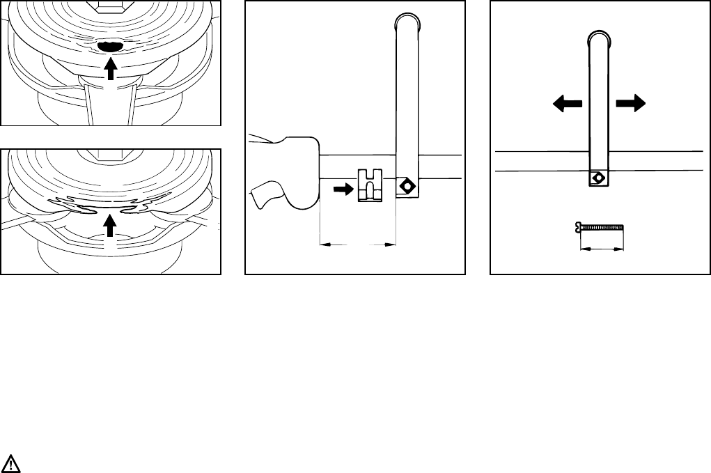
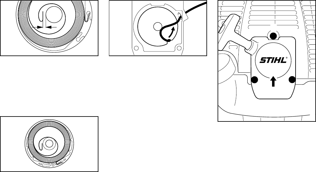
Check wear limit marks at regular
intervals.
Wear limit marks are incorporated in the
base of the PolyCut.
Stop using your PolyCut 5-3
immediately if one of the round holes
(1; arrow) becomes visible, or if the
upright rim (2; arrow) is worn as shown.
Install a new mowing head.
It is essential to observe the wear
limit marks since there is otherwise
a risk of the cutting tool shattering.
Thrown parts may result in personal
injury.
:Fit the loop handle (1) on the drive
tube, 5,9“ (15 cm) forward of the
control handle (2).
:Fit clamp (3) against drive tube and
slide it into the loop handle.
:Insert the square nut (4) in the loop
handle.
:Fit the clamp screw (5) from the
other side and tighten down firmly.
Adjusting loop handle to most
comfortable position
:Loosen the clamp screw (5).
:Slide the loop handle along the drive
tube as required.
:Retighten the clamp screw.
1
002BA073 KN
2
002BA074 KN
Mounting the Loop Handle
3
355BA030 KN
1
2
A
343BA023 KN
5
4
50 mm
( 2" )

15FS 75
English / USA
:For position of carrying eye see
"Parts and Controls"
:Place the clamp (1) with the
tapped hole on the left-hand side
of the drive tube.
:Squeeze the two ends of the clamp
together and hold in that position.
:Insert M 6 x 14 screw (2).
:Line up the carrying eye.
:Tighten down the screw firmly.
* see "Guide to Using this Manual"
:Slip the clamp (1) over the
deflector (2).
:Push deflector with clamp onto the
bearing housing (3) as far as stop.
:Tighten down the clamp.
Preparations
:Lay your trimmer on its back with
the shaft (2) facing up.
STIHL-“AutoCut 11-2“
:Take the thrust plate (1) off the
shaft (2).
STIHL-“PolyCut“
:Fit the thrust plate (1) on the shaft
(2) so that internal hexagon (3)
engages hexagon (4).
Fitting the Carrying Eye*
002BA142 KN
1
2
1
Mounting the Deflector
342BA045 KN
1
23
342BA002 KN
Mounting the Cutting Tools
342BA020 KN
1
2
3
4
16
English / USA
FS 75
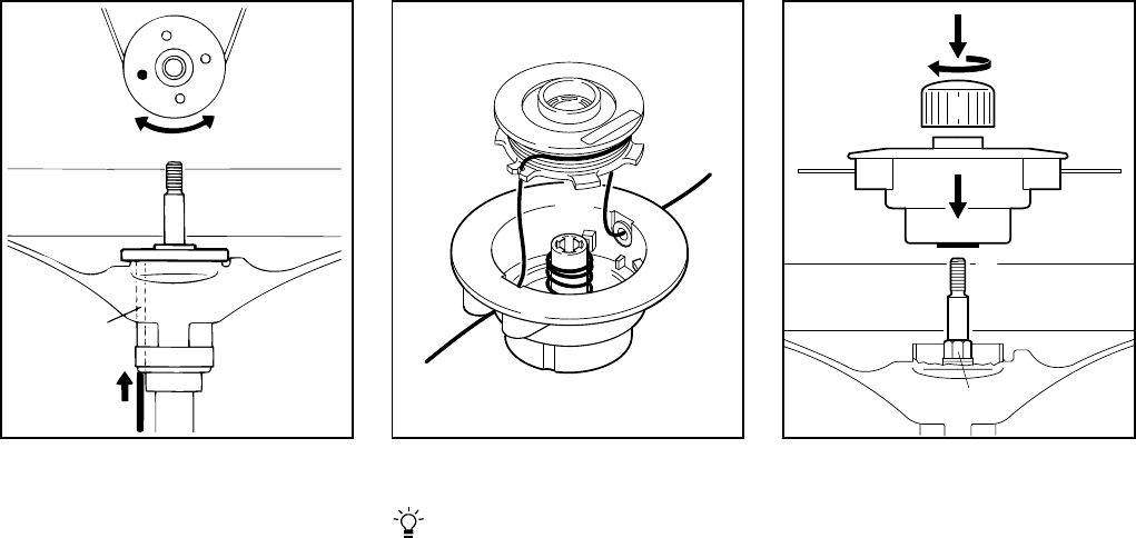
Blocking the Drive Shaft
:Insert the stop pin (1) in the bores
(2) in the defelector and thrust plate.
Turn thrust plate to and fro until the
stop pin slips into position and
blocks the shaft.
Mounting the Mowing Head
Keep instruction sheet for cutting
head in a safe place.
Assembling STIHL AutoCut 11-2
:Fit spring (1) in the spool
housing (2).
:Wind the nylon lines onto the spool:
see "Replacing Nylon Line"
:Assemble the mowing head: see
"Replacing Nylon Line"
:Slip the mowing head (2) over the
shaft (3) and engage hexagon
recess (4) on external hexagon (5).
:Fit the cap (6) on the mowing head
and screw it clockwise onto shaft as
far as stop. Tighten it down firmly.
342BA021 KN
1
2
2
1
681BA014 KN
2
4
3
6
2
5
681BA015 KN

17FS 75
English / USA
STIHL PolyCut 10-3
:Screw the mowing head (7)
clockwise onto the shaft (3) as far
as stop.
:Use stop pin to block the shaft.
:Tighten down the mowing head
firmly.
Remove the stop pin.
STIHL PolyCut 5-3
:Place the nut (8) in the mowing
head.
:Screw the mowing head (7)
clockwise onto the shaft (3) as far
as stop.
:Use stop pin to block the shaft.
:Tighten down the mowing head
firmly.
Remove the stop pin.
Adjusting Nylon Line
STIHL AutoCut 11-2
:Hold the rotating mowing head
horizontal to the ground – tap it on
the ground – about 3 cm (1 1/4")
fresh line is advanced.
:The blade (1) on the deflector (2)
trims surplus line to the correct
length. Avoid tapping the head more
than once.
3
7
681BA016 KN
3
7
8
681BA017 KN
342BA024 KN
1
2

18
English / USA
FS 75
Line feed operates only if both lines
are at least 2.5cm (1") long.
STIHL PolyCut 10-3
Refer to instructions supplied with the
mowing head.
Removing the Mowing Head
:Block the shaft.
:Unscrew the mowing head
counterclockwise.
Replacing Cutting Line
AutoCut
See chapter "Replacing Nylon Line".
PolyCut 10-3
Refer to instructions supplied with the
mowing head.
Replacing Thermoplastic Blades
PolyCut
Follow the instructions supplied with the
mowing head.
This engine is certified to operate on
unleaded gasoline and the STIHL two-
stroke engine oil at a mix ratio of 50:1.
Your two-stroke engine requires a
mixture of high-quality gasoline and
quality two-stroke air cooled engine oil.
Use mid-grade unleaded gasoline with a
minimum octane rating of 89 (R+M/2). If
the octane rating of the mid-grade
gasoline in your area is lower, use
premium unleaded fuel.
Fuel with a lower octane rating may
increase engine temperatures. This, in
turn, increases the risk of piston seizure
and damage to the engine.
The chemical composition of the fuel is
also important. Some fuel additives not
only detrimentally affect elastomers
(carburetor diaphragms, oil seals, fuel
lines, etc.), but magnesium castings and
catalytic converters as well. This could
cause running problems or even
damage the engine. For this reason
STIHL recommends that you use only
nationally recognized high-quality
unleaded gasoline!
Use only STIHL two-stroke engine oil or
equivalent high-quality two-stroke
engine oils that are designed for use
only in air cooled two-cycle engines.
We recommend STIHL 50:1 two-stroke
engine oil since it is specially formulated
for use in STlHL engines.
Do not use BIA or TCW rated (two-
stroke water cooled) mix oils or other
mix oils that state they are for use in both
water cooled and air cooled engines
(e.g., outboard motors, snowmobiles,
chainsaws, mopeds, etc.).
Take care when handling gasoline.
Avoid direct contact with the skin and
avoid inhaling fuel vapor. When filling at
the pump, first remove the canister from
your vehicle and place the canister on
the ground before filling. Do not fill fuel
canisters that are sitting in or on a
vehicle.
The canister should be kept tightly
closed in order to avoid any moisture
getting into the mixture.
The machine‘s fuel tank and the canister
in which fuel mix is stored should be
cleaned as necessary.
Fuel
19FS 75
English / USA
Fuel mix ages
Only mix sufficient fuel for a few days
work, not to exceed 3 months of storage.
Store in approved fuel-canisters only.
When mixing, pour oil into the canister
first, and then add gasoline. Close the
canister and shake it vigorously by hand
to ensure proper mixing of the oil with
the fuel.
Dispose of empty mixing-oil canisters
only at authorized disposal locations.
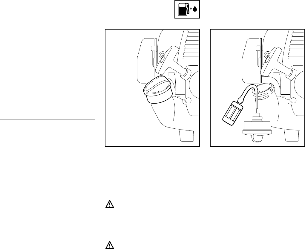
Before fueling, clean the filler cap and
the area around it to ensure that no dirt
falls into the tank.
Always thoroughly shake the mixture in
the canister before fueling your
machine.
In order to reduce the risk of burns
or other personal injury from
escaping gas vapor and fumes,
remove the fuel filler cap carefully
so as to allow any pressure build-up
in the tank to release slowly.
After fueling, tighten fuel cap as
securely as possible by hand.
Change the fuel pick up body every
year.
Before storing your machine for a long
period, drain and clean the fuel tank and
run engine until carburetor is dry.
Gaso-
line
Oil (STIHL 50:1 or
equivalent high-quality oils)
US gal. US fl.oz
12.6
2 1/2 6.4
512.8
Fueling
389BA031 KN
389BA032 KN

20
English / USA
FS 75
Shoulder Strap*
:Put on the shoulder strap (1).
:With the brushcutter attached,
adjust length of strap until the spring
hook (2) is about a hand’s width
below your right hip.
*see "Guide to Using this Manual"
Controls
Throttle trigger interlock (1)
Throttle trigger (2)
Slide control (3)
Positions of Slide Control
STOP-O (4) – engine off – the ignition is
switched off
# – normal run position (5) – the engine
is running or can start
START (6) - the ignition is switched on,
the engine can start
Symbol on slide control
h (7) – stop symbol and arrow – to stop
the engine, push the slide control in
direction of the arrow on the stop symbol
(h ) to STOP-O.
Starting
:Hold down the throttle trigger
interlock and squeeze the throttle
trigger.
:While holding both levers in this
position, move the slide control to
START and hold it there.
:Now release the throttle trigger,
slide control and trigger interlock in
that order. This is the starting
throttle position.
Fitting the Harness
1
392BA039 KN
2
Starting / Stopping
the Engine
3
STOP
2
5
6
4
7
002BA181 KN
START
STOP-
1
21FS 75
English / USA
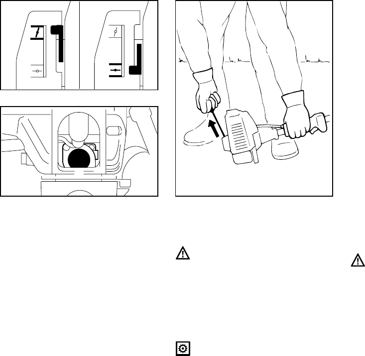
:Set the choke lever (8):
For cold start to g
For warm start to e
– also use this position if the engine
has been running but is still cold.
:Press fuel pump bulb (9) at least five
times even if bulb is filled with fuel.
:Put the unit on the ground:
It must rest securely on the engine
support and deflector.
Check that the cutting tool is not
touching the ground or any other
obstacles.
:Make sure you have a firm footing.
:Hold the unit with your left hand on
the control handle and press it down
firmly – your thumb should be
under the control handle.
Do not stand or kneel on the drive
tube! This could permanently
damage the drive tube.
:Pull the starter grip slowly with your
right hand until you feel it engage –
and then give it a brisk strong pull.
Do not pull out the starter rope all
the way – it might break.
:Do not let the starter grip snap
back – guide it slowly into the
housing so that the starter rope can
rewind properly.
:Continue cranking until the engine
runs.
When engine begins to fire:
:Move choke lever to e
:Continue cranking.
As soon as engine runs:
:Blip the throttle trigger –
the slide control moves to the run
position # – and the engine returns
to idling speed.
Make sure carburetor is correctly
adjusted – the cutting tool must not
rotate when the engine is idling.
Your power tool is ready for
operation.
393BA017 KN
8
8
393BA018 KN
9
355BA007 KN
22
English / USA
FS 75
To shut down the engine:
:Push the slide control in the
direction of the arrow (h ) to
STOP-O.
Other points to observe when
starting
At very low outside temperatures
As soon as engine runs:
:Blip the throttle trigger to disengage
the starting throttle position –
the slide control moves to the run
position # – and the engine settles
down to idle speed.
:Allow engine to warm up for a brief
period at part throttle.
If the engine does not start
If you did not move the choke lever to
e quickly enough after the engine
began to fire, the combustion chamber is
flooded.
:Move the choke lever to e
:Set the slide control, interlock lever
and throttle trigger to the starting
throttle position.
:Start the engine by pulling the
starter rope briskly – 10 to 20 pulls
may be necessary.
If the engine still does not start
:Push the slide control in the
direction of the arrow (h ) to
STOP-O.
:Pull off the spark plug boot (10).
:Unscrew and dry off the spark plug.
:Open the throttle wide.
:Crank the engine several times with
the starter to clear the combustion
chamber.
:Refit the spark plug.
:Connect the spark plug boot (press
it down firmly).
:Move the slide control to START.
:Set the choke lever to e – even if
engine is cold.
:Now start the engine.
Throttle cable adjustment
:Check adjustment of throttle cable
– see "Adjusting the Throttle Cable".
Fuel tank run until dry
:After refueling, press the fuel pump
bulb at least five times – even if bulb
is filled with fuel.
:Set the choke lever to suit the
engine temperature.
:Now start the engine.
393BA019 KN
10
23FS 75
English / USA
During break-in period
A factory new machine should not be run
at high revs (full throttle off load) for the
first three tank fillings. This avoids
unnecessary high loads during the
break-in period. As all moving parts
have to bed in during the break-in
period, the frictional resistances in the
engine are greater during this period.
The engine develops its maximum
power after about 5 to 15 tank fillings.
During operation
After a long period of full-throttle
operation, allow engine to run for a while
at idle speed so that the heat in the
engine can be dissipated by flow of
cooling air. This protects engine-
mounted components (ignition,
carburetor) from thermal overload.
After finishing work
Wait for engine to cool down. Drain the
fuel tank. Store the machine in a dry
place. Check tightness of nuts and
screws (not adjusting screws) at regular
intervals and retighten as necessary.
Dirty air filters reduce engine power
increase fuel consumption and make
starting more difficult.
If there is a noticeable loss of engine
power
:Move choke lever to g.
:Press in the tab (1).
:Ease the filter cover (2) over the tab
and take it away.
:Clean away loose dirt from around
the filter.
:Remove the foam and felt filter
elements.
:Wash the foam element in a clean,
non-flammable cleaning solution
(e.g. warm soapy water) and then
dry.
:Fit new felt element.
As a temporary measure you can
knock it out on the palm of your
hand or blow it out with compressed
air. Do not wash.
Replace damaged parts!
:Install the foam element (3) in the
filter cover (2).
:Place felt element (4) (lettering
facing inward) in filter housing (5).
:Fit filter cover so that it snaps into
position.
Operating Instructions Cleaning the Air Filter
355BA014 KN
2
1
23
355BA031 KN
45
355BA032 KN
24
English / USA
FS 75
Exhaust emissions are controlled by the
design of the fundamental engine
parameters and components (e.g.
carburation, ignition, timing and valve or
port timing) without the addition of any
major hardware.
The carburetor comes from the factory
with a standard setting.
This setting provides an optimum fuel-air
mixture under most operating
conditions.
With this carburetor it is only possible to
adjust the engine idle speed within fine
limits.
Standard Setting
:Shut off the engine.
:Mount approved cutting head
:Check the air filter and replace if
necessary.
:Check spark arresting screen* and
clean or replace as necessary.
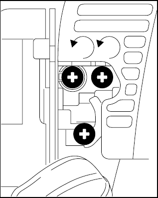
:Turn high speed screw (H)
counterclockwise (max. 3/4 turn)
as far as stop.
:Carefully screw the low speed
screw (L) down onto its seat. Then
open it one turn counterclockwise.
:Start and warm up the engine.
:Adjust idle speed with the idle speed
screw (LA) so that the cutting head
does not rotate.
Fine Tuning
A slight correction of the setting of the
high speed screw (H) may be necessary
if engine power is not satisfactory when
operating at high altitude or at sea level.
* see “Guide to Using this Manual”
Motor Management Adjusting the Carburetor
265BA024 KN
LA
HL
1
3 / 4

25FS 75
English / USA
Rule of thumb
Turn high speed screw (H) about
1/4 turn for every 1000m (3300 ft)
change in altitude.
Conditions for adjustment
Make sure the cutting lines are full
length (as far as limiter blade on the
deflector).
:Carry out standard setting.
:Warm up engine for about 3
minutes.
:Open the throttle wide.
At high altitude
:Turn high speed screw (H) clock-
wise (leaner) no further than stop
until there is no noticeable increase
in engine speed.
At sea level
:Turn high speed screw (H) counter-
clockwise (richer) no further than
stop until there is no noticeable
increase in engine speed.
It is possible that maximum engine
speed may be reached with the
standard setting in each case.
Adjusting Idle Speed
It is usually necessary to change the
setting of the idle speed screw (LA)
after every correction to the low speed
screw (L).
:Warm up engine for about 3
minutes.
Engine stops while idling
:Turn idle speed screw (LA) slowly
clockwise until the engine runs
smoothly – cutting head must not
rotate.
Cutting head rotates when engine is
idling
:Turn idle speed screw (LA) slowly
counterclockwise until cutting blade
stops rotating and then turn the
screw about another 1/2 to 1 turn in
the same direction.
Erratic idling behavior, engine stops
even though setting of LA screw is
correct, poor acceleration
Idle setting too lean:
:Turn low speed screw (L)
counterclockwise (about 1/4 turn)
until the engine runs and
accelerates smoothly.
Erratic idling behavior
Idle setting too rich:
:Turn low speed screw (L) clockwise
(about 1/4 turn) until the engine runs
and accelerates smoothly.
26
English / USA
FS 75
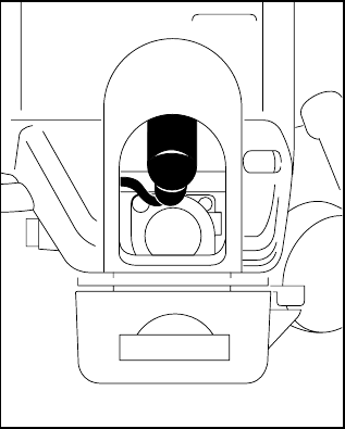
If the engine is low on power, check the
spark arresting screen in the muffler.
:Lift spark arresting screen and pull it
out sideways.
:Clean spark arresting screen if
necessary.
:If screen is damaged or coked up, fit
a new one.
:Refit the spark arresting screen.
* see “Guide to Using this Manual”
Wrong fuel mix (too much engine oil in
the gasoline), a dirty air filter and
unfavorable running conditions (mostly
at part throttle etc.) affect the condition of
the spark plug. These factors cause
deposits to form on the insulator nose
which may result in trouble in operation.
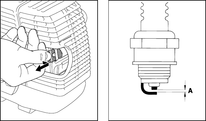
If engine is down on power, difficult to
start or runs poorly at idling speed, first
check the spark plug.
:Remove spark plug – see “Starting /
Stopping the Engine“.
:Clean dirty spark plug.
:Check electrode gap (A) and
readjust if necessary – see
"Specifications".
:Use only resistor type spark plugs
of the approved range.
Rectify problems which have caused
fouling of spark plug:
:Too much oil in fuel mix.
:Dirty air filter.
:Unfavorable running conditions,
e.g. operating at part load.
Fit a new spark plug after approx.
100 operating hours
or earlier if the electrodes are badly
eroded.
Spark Arresting Screen* in
Muffler
392BA035 KN
Checking the Spark Plug
000BA002 KN

27FS 75
English / USA
To reduce the risk of fire and burn
injury, use only spark plugs
authorized by STIHL. Always press
spark plug boot (2) snugly onto
spark plug terminal (1) of the proper
size. (Note: If terminal has
detachable SAE adapter nut, it must
be attached.)
A loose connection between spark
plug boot and ignition wire
connector in the boot may create
arcing that could ignite combustible
fumes and cause a fire.
Removing the Starter Cover
:Take out the screws (1).
:Lift the starter cover (2) away from
the tank (3) and pull it out from
under the shroud (4).
Removing the Rope Rotor
:Take out the screw (5).
:Remove the rope rotor very
carefully.
The rewind spring is seated in the
rope rotor and may pop out and
uncoil if care is not taken.
The pieces of broken spring may be
under tension and fly apart
unexpectedly when you remove the
rope rotor. To help reduce the risk of
injury, wear face protection and
gloves.
000BA036 TR
1
Replacing the Starter Rope
and Rewind Spring
1
11
2
3
4
392BA013 KN
5
392BA014 KN

28
English / USA
FS 75
Replacing the Starter Rope
:Use a screwdriver to pry the cap (6)
out of the starter grip.
:Remove remaining rope from the
rotor and grip, making sure the
ElastoStart sleeve is not pushed out
of the grip.
:Tie a simple overhand knot in the
end of the new starter rope (see
Specifications) and then thread the
rope through the top of the grip and
the rope bushing (7).
:Refit the cap in the grip.
:Pull the rope through the rotor and
secure it with a simple overhand
knot.
:Go to "Installing the rope rotor".
Replacing a Broken Rewind
Spring
Two types of replacement spring are
available from the factory:
– A ready-to-fit rewind spring secured
with a wire retainer.
– A rope rotor with pre-installed
rewind spring.
Installing the ready-to-fit rewind
spring
:Lubricate the spring with a few
drops of non-resinous oil – see
"Special Accessories" – do not open
the wire retainer!
:Carefully remove the parts of the old
spring from the starter cover and
rope rotor.
:Insert the new rewind spring in the
rope rotor and, at the same time,
engage the outer spring loop in the
rotor’s recess – the wire retainer
slips off in this process.
If the spring pops out and uncoils,
refit it in the counterclockwise
direction, starting outside and
working inwards.
:Go to "Installing the Rope Rotor".
Installing rope rotor with rewind
spring
:Carefully unpack the new rope rotor
with rewind spring. The spring may
pop out if not handled with care –
risk of injury.
:Lubricate the spring with a few
drops of non-resinous oil – see
"Special Accessories".
:Go to "Installing the Rope Rotor".
6
7
392BA015 KN
392BA024 KN
29FS 75
English / USA
Installing the Rope Rotor
:Check dimension a for inner spring
anchor loop and bend it slightly if
necessary.
:Coat rope rotor bearing bore with
non-resinous oil – see "Special
Accessories".
:Slide the rotor onto the starter post –
turn it back and forth until the rewind
spring anchor loop (8) engages.
:Insert the screw (5) and tighten it
down securely.
:Go to "Tensioning the Rewind
Spring".
Tensioning the Rewind Spring
:Make a loop in the unwound
starter rope and use it to turn
the rope rotor six full revolutions
counterclockwise. Hold the rotor
steady – straighten the twisted rope
– release the rotor –
let go of rope slowly so that it winds
onto the rotor.
:Check spring tension:
– The starter grip must be firmly
seated in the rope guide bushing.
If the grip droops to one side: Add
one more turn on rope rotor to
increase spring tension.
– When the starter rope is fully
extended it must be possible to
rotate the rotor another half turn. If
this is not the case, the spring is
overtensioned and could break.
Take one turn of rope off the rotor.
:Go to "Fitting the Starter Cover".
Fitting the Starter Cover
:Push the upper mounting boss (2)
under the shroud (4) –
line up the tank (3)and push the
lower part of cover onto the tank.
:Insert and tighten down the housing
screws (1).
a
389BA029 KN
a = 2mm
(0.08 in)
8
392BA025 KN
392BA044 KN
1
11
2
3
4
393BA045 KN
30
English / USA
FS 75
For periods of about 3 months or longer
:Drain and clean the fuel tank in a
well ventilated area.
:Run engine until carburetor is dry –
this helps prevent carburetor
diaphragms sticking together.
:Remove, clean and inspect the
cutting tool.
:Thoroughly clean the machine – pay
special attention to the cylinder fins
and air filter.
:Store the machine in a dry, high or
locked location – out of the reach of
children and other unauthorized
persons.
:Dispose of remaining fuel and
cleaning solution properly in
accordance with local
environmental requirements.
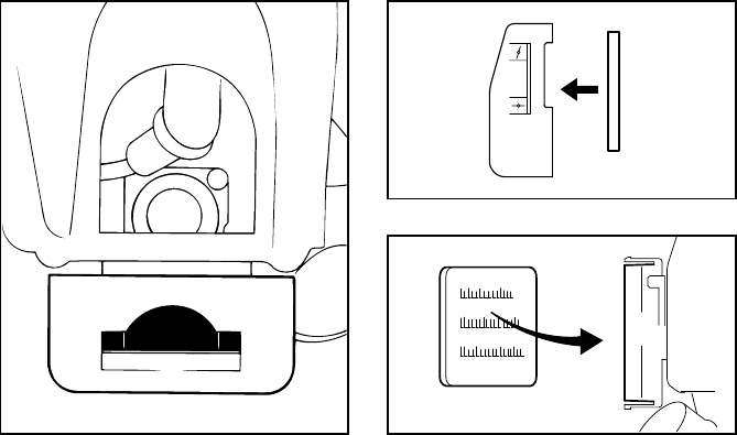
Always inspect the mowing head for
signs of wear before replacing the nylon
line.
If there are signs of severe wear, it
may be necessary to replace some
parts or thecomplete mowing head.
Preparations
:Shut off the engine.
:Lay your brushcutter on its back
with the mowing head facing up.
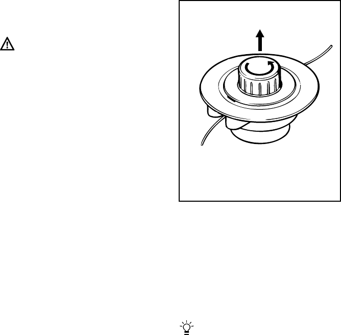
Removing Remaining Nylon Line
:Open the mowing head. To do this,
Hold the mowing head steady and
rotate the cap (1) counterclockwise.
:Disengage the spool (2), take it out
of the mowing head and remove the
remaining line.
Winding Line onto Spool
A prewound spool** may be
installed to save the following
procedure.
** see "Special Accessories"
Storing the Machine Replacing Nylon Line
STIHL AutoCut 11-2
681BA008 KN
1
2
31FS 75
English / USA
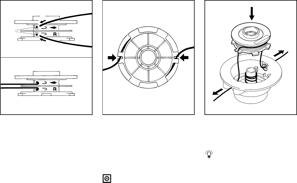
:Use green-coded nylon line with a
diameter of 0.080" (2 mm).
:Cut two 10-ft (3m) lengths of nylon
line from the reel**.
:Insert the end of each line (3) in the
holes (4) in the spool.
:Bend the ends of the lines over the
edge of the holes to form a hook.
** see "Special Accessories"
:Straighten out the nylon lines and
wind them tightly onto the spool –
one nylon line in each chamber.
:Engage the ends of the nylon lines
in the notches (5).
Assembling the Mowing Head
Check that the compression spring
is installed (see “Mounting the
Mowing Head”).
:Thread the ends of the lines (6)
through the sleeves (7) and push
spool (2) into the head so that it
snaps into position.
Nylon lines must disengage from
notches (5) as the spool is pushed
into position.
:Pull out the ends of the lines as far
as stop.
:Mount the mowing head on the
machine.
681BA009 KN
4
3
3
681BA010 KN
5
5
7
681BA011 KN
2
6
6

32
English / USA
FS 75
* see “Guide to Using this Manual”
Maintenance Chart
Please note that the following maintenance intervals apply for normal operating
conditions. If your daily working time is longer than normal or cutting conditions
are difficult (very dusty work area etc.), shorten the specified intervals accordingly.
before
starting work
after finishing
work or daily
after each
refueling stop
weekly
monthly
every 12 months
if problem
if damaged
as required
Complete machine
Visual inspection
(condition, leaks) XX
Clean X
Control handle Check operation XX
Air filter Clean XX
Replace X
Pick up body in fuel tank Check X
Replace XXX
Fuel tank Clean XX
Carburetor
Check idle adjustment - cutting
tool must not turn XX
Readjust idle X
Spark plug Readjust electrode gap X
Cooling inlets Inspect X
Clean X
Spark arresting screen* in muffler Inspect XX
Clean or replace XX
All accessible screws and nuts (not adjusting
screws) Retighten X
Anti-vibration element Have replaced by STIHL dealer X
Cutting tool
Visual inspection XX
Replace X
Check tightness
of cutting tool XX
33FS 75
English / USA
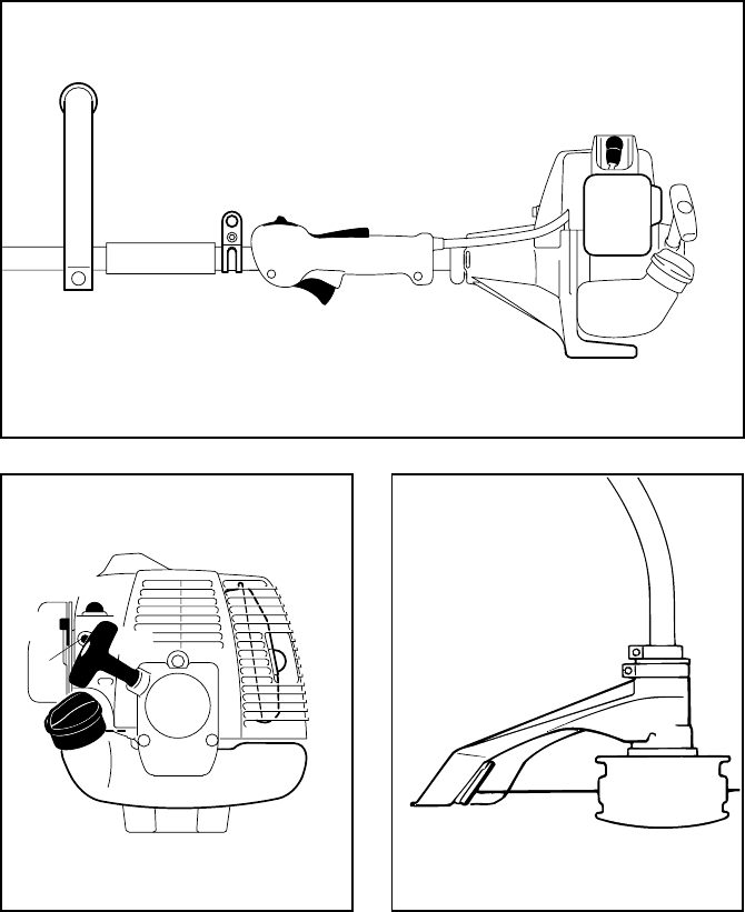
1 Loop handle
2Slide control
3 Throttle trigger interlock
4 Throttle trigger
5 Spark plug boot
6 Air filter cover
7Machine support
8 Carrying ring (clamp)*
# Serial number
9 Fuel tank
10 Fuel filler cap
11 Starter grip
12 Fuel pump
13 Choke lever
14 Carburetor adjusting screws
15 Muffler
(with spark arresting screen*)
16 Deflector
17 Line limiting blade
18 Mowing head
* see “Guide to Using this Manual”
Parts and Controls
2
392BA040 KN
1
3
4
5
6
7
#
8
10 9
11
12
13
14 15
392BA041 KN
17
392BA042 KN
18
16
34
English / USA
FS 75
Definitions
1. Loop Handle
For easy control of machine during
cutting work.
2. Slide Control
For starting throttle, run and stop.
Keeps the throttle partially open
during starting, switches the
engine’s ignition off to stop the
engine.
3. Throttle Trigger Interlock
Must be depressed before the
throttle trigger can be activated.
4. Throttle Trigger
Controls the speed of the engine.
5. Spark Plug Boot
Connects the spark plug to the
ignition lead.
6. Air Filter Cover
Protects the air filter.
7. Machine Support
For resting machine on the ground.
8. Carrying Ring (Clamp)
Connects the brushcutter to the
harness.
9. Fuel Tank
For fuel mixture consisting of
gasoline and oil.
10. Fuel Filler Cap
For closing the fuel tank.
11. Starter Grip
The grip of the pull starter, which is
the device to start the engine.
12. Fuel Pump
Provides additional fuel feed for a
cold start.
13. Choke Lever
Eases engine starting by enriching
mixture.
14. Carburetor Adjusting Screws
For tuning the carburetor.
15. Muffler
(with spark arresting screen)
Reduces exhaust noises and
diverts exhaust gases away from
operator.
16. Deflector
Designed to reduce the risk of injury
from foreign objects flung
backwards toward the operator by
the cutting tool and from contact
with the cutting tool.
17. Line Limiting Blade
Blade mounted to the deflector that
trimes over-long nylon line to the
correct length.
18. Mowing Head
The cutting attachment for different
purposes (special accesory).
35FS 75
English / USA
Engine
EPA:
The Emission Compliance Period
referred to on the Emissions
Compliance Label indicates the number
of operating hours for which the engine
has been shown to meet Federal
emission requirements.
Category A = 300 hours, B = 125 hours,
C = 50 hours
CARB:
The Emission Compliance Period used
on the CARB Air Index Label indicates
the terms:
Extended = 300 hours
Intermediate = 125 hours
Moderate = 50 hours
Ignition System
Fuel System
Rewind Starter
Weight
* see “Guide to Using this Manual”
Single cylinder two-stroke engine
Displacement: 1.55 cu.in
(25.4cm3)
Bore: 1.34 in (34 mm)
Stroke: 1.10 in (28 mm)
Power according to
ISO 8893: 1.3 bhp
(0.95 kW)
Max. speed of
output shaft (cutting
tool mounting) 7500 rpm
Idle speed: 2800 rpm
Specifications
Type: Electronic magneto ignition
Spark plug
(suppressed):
Bosch WSR 6 F or
NGK BPMR 7 A or
Champion RCJ 6Y
Electrode gap: 0.02 in (0.5 mm)
Spark plug
thread:
M 14 x 1.25;
0.37 in (9.5 mm)
lang
Carburetor: All position diaphragm
carburetor with integral fuel pump
Air filter: Foam and felt
elements
Fuel tank capacity: 0.93 US.pt
(0.44 L)
Fuel mix: See “Fuel”
Starter rope:
0.12 in (3.0 mm) diameter
Length
31.5 in (800 mm)*
33.5 in (850 mm)*
without cutting tool and
deflector 9.26 lb
(4.2 kg)
36
English / USA
FS 75
Cutting Tools
STIHL AutoCut 11-2
Nylon lines:
0.080“ (2.0 mm) diameter, green,
several lengths
0.095“ (2.4 mm) diameter, orange,
several lengths
Prewound spool (with nylon line)
STIHL PolyCut 5-3
Thermoplastic blades (pack of 12)
Thrust plate
Locking pin
Other Special Accessories
Safety glasses
Shoulder strap
Combination wrench
Thrust plate
STIHL ElastoStart (starter rope with grip)
Special resin-free lubricating oil
3.38 fl.oz. (100 ml) bottle
Contact your STIHL dealer for the latest
information on these and other special
accessories.
The user of this unit should carry out
only the maintenance operations
described in this manual. Other repair
work may be performed only by an
authorized STIHL dealer.
Warranty claims following repairs can be
accepted only if the repair has been
performed by an authorized STIHL
dealer using original STIHL replacement
parts.
Original STlHL parts can be identified by
the STIHL part number, the
STIHl
logo and the STlHL parts symbol (.
The symbol may appear alone on small
parts.
Special Accessories Maintenance and Repairs
37FS 75
English / USA
Your Warranty Rights
and Obligations
The U.S. Environmental Protection
Agency (EPA), the California Air
Resources Board (CARB) and STIHL
Incorporated are pleased to explain the
Emission Control System Warranty on
your model year 2000 and later
equipment type engine. In California,
new small off-road engines must be
designed, built and equipped to meet the
State's stringent anti-smog standards. In
other states, new 1997 and later model
year small off-road equipment engines
must be designed, built and equipped, at
the time of sale, to meet the U.S. EPA
regulations for small non road engines.
The equipment engine must be free from
defects in materials and workmanship
which cause it to fail to conform with
U.S. EPA standards for the first two
years of engine use from the date of sale
to the ultimate purchaser.
STIHL Incorporated must warrant the
emission control system on your small
off-road engine for the period of time
listed below provided there has been no
abuse, neglect or improper maintenance
of your small off-road equipment engine.
Your emission control system includes
parts such as the carburetor and the
ignition system. Also included may be
hoses, and connectors and other
emission related assemblies.
Where a warrantable condition exists,
STIHL Incorporated will repair your
small off-road equipment engine at no
cost to you, including diagnosis (if the
diagnostic work is performed at an
authorized dealer), parts, and labor.
Manufacturer's Warranty
Coverage:
The small off-road equipment engines
are warranted for two years in California.
In other states, 1997 and later model
year small off-road equipment engines
are also warranted for two years. If any
emission-related part on your engine is
defective, the part will be repaired or
replaced by STIHL Incorporated free of
charge.
Owner's Warranty
Responsibilities:
As the small off-road equipment engine
owner, you are responsible for the per-
formance of the required maintenance
listed in your owner's manual. STIHL
Incorporated recommends that you
retain all receipts covering maintenance
on your small off-road equipment
engine, but STIHL Incorporated cannot
deny warranty solely for the lack of
receipts or for your failure to ensure the
performance of all scheduled
maintenance.
Any replacement part or service that is
equivalent in performance and durability
may be used in non-warranty mainten-
ance or repairs, and shall not reduce the
warranty obligations of the engine
manufacturer.
As the small off-road equipment engine
owner, you should be aware, however,
that STIHL Incorporated may deny you
warranty coverage if your small off-road
equipment engine or a part has failed
due to abuse, neglect, improper
maintenance or unapproved
modifications.
You are responsible for presenting your
small off-road equipment engine to a
STIHL service center as soon as a
problem exists. The warranty repairs will
be completed in a reasonable amount of
time, not to exceed 30 days.
If you have any questions regarding your
warranty rights and responsibilities,
please contact a STIHL customer
service representative at
1-800-467-8445 or you can write to
STIHL Inc., 536 Viking Drive,
P.O . B o x 2 0 15 ,
Virginia Beach, VA 23450-2015.
Coverage by STIHL Incorporated
STIHL Incorporated warrants to the
ultimate purchaser and each
subsequent purchaser that your small
off-road equipment engine will be
designed, built and equipped, at the time
of sale, to meet all applicable
regulations. STIHL Incorporated also
warrants to the initial purchaser and
each subsequent purchaser that your
engine is free from defects in materials
and workmanship which cause the
engine to fail to conform with applicable
regulations for a period of two years.
STIHL Incorporated Federal and California
Emission Control Warranty Statement
38
English / USA
FS 75
Warranty Period
The warranty periods will begin on the
date the utility equipment engine is
purchased by the initial purchaser and
you have signed and sent back the
warranty card to STIHL. If any emission
related part on your engine is defective,
the part will be replaced by STIHL
Incorporated at no cost to the owner.
Any warranted part which is not
scheduled for replacement as required
maintenance, or which is scheduled only
for regular inspection to the effect of
"repair or replace as necessary" will be
warranted for the warranty period.
Any warranted part which is scheduled
for replacement as required mainten-
ance will be warranted for the period of
time up to the first scheduled replace-
ment point for that part.
Diagnosis
You, as the owner, shall not be charged
for diagnostic labor which leads to the
determination that a warranted part is
defective. However, if you claim
warranty for a component and the
machine is tested as non-defective,
STIHL Incorporated will charge you for
the cost of the emission test.
Mechanical diagnostic work will be
performed at an authorized STIHL
servicing dealer. Emission test may be
performed either at STIHL Incorporated
or at any independent test laboratory.
Warranty Work
STIHL Incorporated shall remedy war-
ranty defects at any authorized STIHL
servicing dealer or warranty station. Any
such work shall be free of charge to the
owner if it is determined that a warranted
part is defective. Any manufacturer-
approved or equivalent replacement part
may be used for any warranty
maintenance or repairs on emission-
related parts and must be provided
without charge to the owner. STIHL
Incorporated is liable for damages to
other engine components caused by the
failure of a warranted part still under
warranty.
The California Air Resources Board's
Emission Warranty Parts List specifically
defines the emission-related warranted
parts. These warranted parts are:
Carburetor
Choke (Cold start enrichment system)
Intake manifold
Air filter
Spark plug
Magneto or electronic ignition system
(ignition module)
Catalytic converter (if applicable)
Fasteners
Where to make a claim for
Warranty Service
Bring the product to any authorized
STIHL servicing dealer and present the
signed warranty card.
Maintenance Requirements
The maintenance instructions in this
manual are based on the application of
the recommended 2-stroke fuel-oil
mixture (see also instruction "Fuel").
Deviations from this recommendation
regarding quality and mixing ratio of fuel
and oil may require shorter maintenance
intervals.
Limitations
This Emission Control Systems War-
ranty shall not cover any of the following:
:repair or replacement required
because of misuse, neglect or lack
of required maintenance,
:repairs improperly performed or
replacements not conforming to
STIHL Incorporated specifications
that adversely affect performance
and/or durability, and alterations or
modifications not recommended or
approved in writing by STIHL
Incorporated,
and
:replacement of parts and other
services and adjustments
necessary for required maintenance
at and after the first scheduled
replacement point.
39FS 75
español / EE.UU
BA_SE_068_007_31_04.fm Impreso en papel sin cloro.
Las tintas contienen aceites vegetales,el papel es reciclable.
© ANDREAS STIHL AG & Co. KG, 2004
0458 392 3021. M3. A4. PM. Printed in USA
STIHl
Contenido
Guía para el uso
de este manual ............................... 40
Medidas de seguridad y
técnicas de manejo ........................ 41
Montaje del mango tórico ............... 52
Colocación de la argolla
de transporte* ................................. 53
Montaje del deflector ...................... 53
Montaje de las herramientas
de corte .......................................... 53
Combustible ................................... 56
Llenado de combustible ................. 57
Colocación del arnés ...................... 58
Arranque / parada del motor ........... 58
Instrucciones de manejo ................ 61
Limpieza del filtro de aire ............... 61
Manejo del motor ............................ 62
Ajuste del carburador ..................... 62
Chispero* en silenciador ................ 64
Revisión de la bujía ........................ 64
Sustitución de la cuerda de
arranque y resorte de rebobinado .. 65
Almacenamiento de la máquina ..... 68
Sustitución del hilo de nilón ............ 68
Tabla de mantenimiento ................. 70
Piezas y controles .......................... 71
Especificaciones ............................. 73
Accesorios especiales .................... 74
Mantenimiento y reparación ........... 74
Declaración de garantía de STIHL
Incorporated sobre sistemas
de control de emisiones según
normas Federales y del Estado
de California ................................... 75
* vea "Guía para el uso de este
manual"
Permita que solamente las personas
que comprenden la materia tratada en
este manual manejen su orilladora.
Para obtener el rendimiento y satisfac-
ción máximos de la orilladora STIHL, es
importante leer y comprender las ins-
trucciones de mantenimiento y las pre-
cauciones de seguridad antes de usarla.
Comuníquese con el concesionario o
distribuidor de STIHL si no se entiende
alguna de las instrucciones dadas en el
presente manual.
!Advertencia
Dado que la orilladora es una herra-
mienta de corte motorizada de gran
velocidad, es necesario tomar medidas
especiales de seguridad para reducir el
riesgo de lesiones.
El uso descuidado o inadecuado puede
causar lesiones graves e incluso morta-
les. Asegúrese que su máquina esté
equipada con el deflector, mango y
arnés adecuados para el tipo de acceso-
rio de corte que se está utilizando. Siem-
pre protéjase adecuadamente los ojos.
La filosofía de STIHL es mejorar conti-
nuamente todos su productos. Como
resultado, de vez en cuando se llevan a
cabo modificaciones y mejoramientos
técnicos. Si las características de fun-
cionamiento o la apariencia de su orilla-
dora difieren de aquéllas descritas en
este manual, le rogamos ponerse en
contacto con el concesionario STIHL
para recibir más información y asisten-
cia.

40
español / EE.UU
FS 75
Pictogramas
Todos los pictogramas que se encuen-
tran en la máquina se muestran y expli-
can en este manual.
Las instrucciones de uso y manipulación
vienen acompañadas de ilustraciones.
Símbolos en el texto
Los pasos individuales o procedimientos
descritos en el manual pueden estar
señalados en diferentes maneras:
:Paso o procedimiento sin referencia
directa a una ilustración.
Descripción del paso o procedimiento
que se refiere directamente a la ilustra-
ción y contiene los números de referen-
cia que aparecen en la ilustración.
Ejemplo:
Suelte el tornillo (1)
Palanca (2) ...
Además de las instrucciones de uso,
en este manual pueden encontrarse
párrafos a los que usted debe prestar
atención especial. Tales párrafos están
marcados con los símbolos que se
describen a continuación:
Advertencia donde existe el
riesgo de un accidente o lesiones
personales o daños graves a la
propiedad.
Advertencia donde existe el
riesgo de dañar la máquina o
los componentes individuales.
Nota o sugerencia que no es
esencial para el uso de la máquina,
pero puede ayudar al operador a
comprender mejor la situación y
mejorar su manera de manejar la
máquina.
Nota o sugerencia sobre el procedi-
miento correcto con el fin de evitar
dañar el medio ambiente.
Equipo y características
Este manual de instrucciones
abarca varios modelos con diferen-
tes características. Los componen-
tes que no se encuentran instalados
en todos los modelos y las aplica-
ciones correspondientes están mar-
cados con un *. Esos componentes
son ofrecidos como accesorios
especiales por el concesionario
STIHL.
Mejoramientos técnicos
La filosofía de STIHL es mejorar conti-
nuamente todos su productos. Como
resultado de ello, periódicamente se
introducen cambios de diseño y mejo-
ras. Si las características de funciona-
miento o la apariencia de su máquina
difieren de las descritas en este manual,
comuníquese con el concesionario
STIHL para obtener la ayuda que
requiera.
Por lo tanto, no podemos responsabili-
zarnos por los cambios, modificaciones
o mejoramientos que no hayan sido
cubiertos en este manual.
Guía para el uso de este
manual

41FS 75
español / EE.UU
Advertencia
Dado que la orilladora es
una herramienta de corte
que funciona a gran velo-
cidad, es necesario tomar
medidas especiales de seguridad para
reducir el riesgo de lesiones.
Es importante que usted
lea, comprenda bien y
respete las siguientes
advertencias y medidas
de seguridad. Lea el
manual del usuario y las
instrucciones de seguridad periódica-
mente. El uso descuidado o inadecuado
de cualquier orilladora puede causar
lesiones graves e incluso mortales.
Pida a su concesionario STIHL que le
enseñe el manejo de la orilladora. Res-
pete todas las disposiciones, reglamen-
tos y normas de seguridad locales del
caso.
!Advertencia
No preste ni alquile nunca su orilladora
sin entregar el manual del usuario. Ase-
gúrese que todas las personas que utili-
cen su orilladora lean y comprendan la
información contenida en este manual.
!Advertencia
El uso de cualquier orilladora puede ser
peligroso. Si la herramienta de corte
giratoria llega a quedar en contacto con
su cuerpo, le ocasionará una cortadura.
Cuando choca con algún objeto extraño
sólido tal como rocas o pedazos de
metal, puede arrojarlo directamente o
por rebote en dirección de personas que
se encuentren en la cercanía o del ope-
rador. El chocar contra este tipo de obje-
tos puede dañar la herramienta de corte.
Los objetos lanzados o las herramientas
de corte dañadas pueden ocasionar
lesiones graves o mortales al operador o
a personas que se encuentren en la cer-
canía.
!Advertencia
Nunca permita a los niños que usen una
orilladora. No se debe permitir la proxi-
midad de otros, especialmente niños y
animales, donde se esté utilizando la
orilladora.
Nunca deje la orilladora funcionando sin
vigilancia.
Las medidas de seguridad y avisos con-
tenidos en este manual se refieren al
uso de todas las orilladoras de STIHL.
Los distintos modelos pueden contar
con piezas y controles diferentes. Vea la
sección correspondiente de su manual
del usuario para tener una descripción
de los controles y la función de cada
componente de su modelo de orilladora.
El uso seguro de una orilladora atañe a
1. el operador
2. la orilladora
3. el uso de la orilladora
EL OPERADOR
Condición física
Usted debe estar en buenas condicio-
nes físicas y psíquicas y no encontrarse
bajo la influencia de ninguna sustancia
(drogas, alcohol, etc.) que le pueda res-
tar visibilidad, destreza o juicio. No
maneje la orilladora cuando está fati-
gado.
Esté alerta. Si se cansa durante el
manejo de su orilladora, tómese un des-
canso. El cansancio puede provocar
una pérdida del control. El uso de cual-
quier orilladora es fatigoso. Si usted
padece de alguna dolencia que pueda
ser agravada por la fatiga, consulte a su
médico antes de utilizar la orilladora.
Medidas de seguridad y téc-
nicas de manejo

42
español / EE.UU
FS 75
!Advertencia
El uso prolongado de una orilladora (u
otras máquinas) expone al operador a
vibraciones que pueden provocar el
fenómeno de Raynaud (dedos blancos)
o el síndrome del túnel del carpio.
Estas condiciones reducen la capacidad
manual de sentir y regular la tempera-
tura, producen entumecimiento y ardor y
pueden provocar trastornos nerviosos y
circulatorios, así como necrosis de los
tejidos.
No se conocen todos los factores que
contribuyen a la enfermedad de Rayn-
aud, pero el clima frío, el fumar y las
enfermedades o condiciones físicas que
afectan los vasos sanguíneos y la circu-
lación de la sangre, como asimismo los
niveles altos de vibración y períodos
prolongados de exposición a la vibra-
ción son mencionados como factores en
el desarrollo de la enfermedad de Rayn-
aud. Por lo tanto, para reducir el riesgo
de la enfermedad de dedos blancos y
del síndrome del túnel del carpio, sír-
vase notar lo siguiente:
:La mayor parte de las herramientas
motorizadas de STIHL se ofrecen
con un sistema antivibración ("AV")
cuyo propósito es reducir la transmi-
sión de las vibraciones creadas por
el motor a las manos del operador.
Se recomienda el uso del sistema
AV a aquellas personas que utilizan
herramientas motorizadas en forma
constante y regular.
:Use guantes y mantenga las manos
abrigadas.
:Mantenga el sistema AV en buen
estado. Una orilladora con los com-
ponentes flojos o con amortiguado-
res AV dañados o desgastados tam-
bién tendrá tendencia a tener
niveles más altos de vibración.
:Agarre firmemente los mangos en
todo momento, pero no los apriete
con fuerza constante y excesiva;
tómese descansos frecuentes.
Todas las precauciones antes mencio-
nadas no le garantizan que va a estar
totalmente protegido contra la enferme-
dad de Raynaud o el síndrome del túnel
del carpio. Por lo tanto, los operadores
constantes y regulares deben revisar
con frecuencia el estado de sus manos
y dedos. Si aparece alguno de los sínto-
mas arriba mencionados, consulte
inmediatamente al médico.
!Advertencia
El sistema de encendido de la máquina
STIHL produce un campo electromag-
nético de intensidad muy baja. El mismo
puede interferir con algunos tipos de
marcapasos. Para reducir el riesgo de
lesiones graves o mortales, las perso-
nas portadoras de marcapasos deben
consultar a sus médicos y al fabricante
del marcapasos antes de usar esta
máquina.
Vestimenta adecuada
!Advertencia
Para reducir el riesgo de lesiones el
operador debe usar el equipo protector
adecuado.
!Advertencia
El deflector provisto con su orilladora no
siempre protege al operador contra
todos los objetos extraños (gravilla,
vidrio, alambre, etc.) arrojados por la
herramienta de corte giratoria. Los obje-
tos arrojados o lanzados por el acceso-
rio también pueden rebotar y golpear al
operador.
!Advertencia
Para reducir el riesgo de
lesionarse los ojos, nunca
maneje la orilladora si no
tiene puestas gafas o
anteojos de seguridad
bien ajustados con una
protección adecuada en las partes
superior y laterales que satisfagan la
norma ANSI Z 87.1 (o la norma nacional
correspondiente).
Para reducir el riesgo de lesionarse la
cara, STIHL recomienda usar también
una careta o protector facial adecuado
sobre las gafas o anteojos de seguridad.

43FS 75
español / EE.UU
!Advertencia
El ruido de la orilladora
puede dañar los oídos.
Siempre use amortigua-
dores del ruido (tapones u
orejeras) para protegerse
los oídos. Los usuarios
constantes y regulares deben some-
terse con frecuencia a un examen o con-
trol auditivo.
Protéjase las manos con
guantes cuando manipule
la orilladora y la herra-
mienta de corte. Los
guantes gruesos y anti-
deslizantes mejoran el
manejo y protegen las manos.
La ropa debe ser de con-
fección fuerte y ajustada,
pero no tanto que impida
la completa libertad de
movimiento. Evite el uso
de chaquetas sueltas,
bufandas, corbatas, joyas, pantalones
acampanados o con vueltas, pelo largo
suelto o cualquier cosa que pueda
engancharse en las ramas, matorrales o
piezas en movimiento de la máquina.
Use pantalones largos hechos de un
material grueso para protegerse las
piernas. No use pantalones cortos, san-
dalias o pies descalzos. Sujétese el pelo
de modo que quede sobre los hombros.
Una buena base de
apoyo es indispensable
cuando se maneja la ori-
lladora. Póngase botas
gruesas con suela anti-
deslizante. Recomenda-
mos las botas de seguridad con puntera
de acero.
Utilice un casco de segu-
ridad aprobado para redu-
cir el riesgo de lesionarse
la cabeza en caso de
existir tal tipo de peligro.
LA ORILLADORA
Para las ilustraciones y definiciones de
los componentes de la orilladora, vea el
capítulo sobre "Piezas y controles".
!Advertencia
Nunca modifique, de ninguna manera,
una orilladora. Utilice únicamente los
accesorios y repuestos suministrados
por STIHL o expresamente autorizados
por STIHL para usarse con los modelos
específicos de orilladoras de STIHL. Si
bien es posible conectar a la orilladora
de STIHL ciertos accesorios no autori-
zados, su uso puede ser, en la práctica,
extremadamente peligroso.
!Advertencia
Para reducir el riesgo de lesiones al
operador causadas por contacto con la
cuchilla, en las orilladoras FS equipadas
con manillar, mango en "J" o mango
tórico con barra protectora se pueden
usar cuchillas metálicas, pero no en los
modelos FS y FE con mango tórico sola-
mente.
Nunca utilice
algún accesorio de
corte metálico en
el modelo FS cuyo
eje esté combado.

44
español / EE.UU
FS 75
USO DE LA ORILLADORA
Transporte de la orilladora
!Advertencia
Siempre apague el motor y asegúrese
de que el accesorio de corte esté dete-
nido antes de apoyar la orilladora en el
suelo. Cuando transporte su orilladora
en un vehículo, sujétela firmemente
para impedir que su vuelco, el derrame
de combustible y el daño a la orilladora.
Preparación para el uso de la orilla-
dora
Antes de empezar a trabajar, ajuste la
empuñadura del mango de acuerdo a su
tamaño siguiendo a las instrucciones
dadas en el manual del usuario.
Siempre revise la condición y funciona-
miento de su orilladora antes de ponerla
en marcha, especialmente el gatillo de
aceleración, el bloqueo del gatillo de
aceleración (si lo tiene), el interruptor de
parada, la herramienta de corte y el
deflector.
Las flechas en el deflector muestran el
sentido correcto de rotación de la herra-
mienta de corte.
El gatillo de aceleración debe moverse
libremente y siempre debe retornar a la
posición de ralentí por la acción de
resorte. La herramienta de corte debe
estar correctamente apretada y en bue-
nas condiciones de trabajo. Inspeccione
en busca de piezas flojas (tuercas, torni-
llos, etc.).
Llenado de combustible
La orilladora de STIHL utiliza una mez-
cla de aceite-gasolina como combusti-
ble (vea el capítulo "Combustible" en el
manual del usuario).
!Advertencia
La gasolina es un com-
bustible muy inflamable.
Si se derrama y arde a
causa de una chispa u
otra fuente de ignición,
puede provocar un incen-
dio y quemaduras graves o daños a la
propiedad. Tenga sumo cuidado cuando
manipule gasolina o la mezcla de com-
bustible.
No fume cerca del combustible o la ori-
lladora, ni acerque ningún fuego o llama
a ellos.
Instrucciones para el llenado de com-
bustible
!Advertencia
Llene la orilladora de combustible en
lugares al aire libre bien ventilados.
Siempre apague el motor y deje que se
enfríe antes de llenar de combustible.
Dependiendo del combustible utilizado,
de las condiciones climáticas y del sis-
tema de ventilación del tanque, es posi-
ble que se forme vapor de gasolina a
presión dentro del tanque de gasolina.
Para reducir el riesgo de quemaduras,
así como otras lesiones corporales oca-
sionadas por los escapes de vapor de
gasolina y otras emanaciones, quite la
tapa de llenado de combustible de la ori-
lladora cuidadosamente de modo que la
presión que se pueda haber acumulado
en el tanque se disipe lentamente.
Nunca quite la tapa de llenado de com-
bustible mientras el motor está funcio-
nando.
234BA004KN
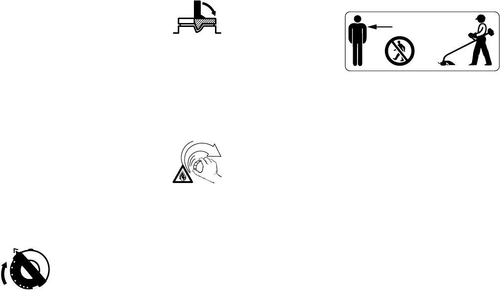
45FS 75
español / EE.UU
Elija una superficie despejada para lle-
nar el tanque y aléjese 3 m (10 pies) por
lo menos del lugar en que lo haya lle-
nado antes de arrancar el motor. Limpie
los derrames de combustible antes de
arrancar la orilladora y compruebe que
no existen fugas.
!Advertencia
Compruebe que no existen fugas de
combustible mientras llena el tanque y
durante el funcionamiento de la
máquina. Si detecta alguna fuga de
combustible o aceite, no arranque el
motor ni lo haga funcionar sin antes
reparar la fuga y limpiar el combustible
derramado. Tenga cuidado de no man-
charse la ropa con combustible. Si la
mancha, cámbiesela inmediatamente.
El tipo de tapa de llenado difiere con los
distintos modelos.
Tapa con empuñadura
!Advertencia
Para reducir el riesgo de derramar com-
bustible y provocar un incendio debido a
una tapa de combustible mal apretada,
coloque la tapa en la posición correcta y
apriétela en la boca de llenado del tan-
que.
Para hacer esto con esta
tapa STIHL, levante la
empuñadura en la parte
superior de la tapa hasta
dejarla vertical a un
ángulo de 90°.
Inserte la tapa en la boca de llenado del
tanque, alineando las marcas triangula-
res en la empuñadura de la tapa y en la
boca del tanque. Utilizando la empuña-
dura, gire la tapa firmemente en sentido
horario hasta donde tope (aprox. un
cuarto de vuelta).
Doble la empuñadura
dejándola a ras con la
parte superior de la tapa.
Si no queda totalmente a
ras y el tope en la empu-
ñadura no encaja en el
hueco correspondiente en el cuello de
llenado, la tapa está mal asentada y
apretada, se deberán repetir los pasos
anteriores.
Tapa roscada
!Advertencia
Las vibraciones de la
máquina pueden aflojar
una tapa de combustible
que ha quedado mal
apretada, o simplemente
soltarla y derramar com-
bustible. Para reducir el riesgo de derra-
mes e incendio, apriete la tapa de lle-
nado de combustible a mano con la
mayor fuerza posible.
Arranque
!Advertencia
Su orilladora es una máquina que debe
ser manejada por solamente una per-
sona. Una vez que está funcionando,
puede arrojar objetos extraños a gran
distancia.
Para reducir el riesgo de ocasionar
lesiones a los ojos u otras partes del
cuerpo, asegúrese que las personas
estén a por lo menos 15 m (50 pies) de
distancia de la máquina. Se debe acon-
sejar a las personas que se encuentran
cerca de la máquina que usen protec-
ción de los ojos. Apague el motor y la
herramienta de corte inmediatamente si
se le aproxima alguna persona. Ponga
en marcha y maneje su orilladora sin
ayuda de nadie. Para las instrucciones
específicas de arranque, vea la sección
correspondiente en el manual del usua-
rio. Coloque la orilladora sobre suelo
firme u otra superficie sólida en un lugar
abierto. Mantenga buen equilibrio con
los pies bien apoyados.
15m (50ft)

46
español / EE.UU
FS 75
!Advertencia
Para reducir el riesgo de lesiones
debido a la pérdida de control, esté
absolutamente seguro que la herra-
mienta de corte se encuentra lejos de su
cuerpo y de todas las obstrucciones y
objetos, incluido el suelo, porque al
arrancar el motor acelerado, su veloci-
dad será lo suficientemente rápida para
que el embrague se engrane y haga
girar la herramienta de corte.
!Advertencia
Cuando tire del mango de arranque, no
enrolle la cuerda de arranque alrededor
de la mano. No deje que el mango retro-
ceda bruscamente, sino guíe la cuerda
de arranque para que se enrolle debida-
mente. Si no ejecuta este procedimiento
puede lastimarse la mano o los dedos y
también dañar el mecanismo de arran-
que.
Con el motor funcionando pero a veloci-
dad de ralentí, enganche la orilladora al
gancho de resorte de su arnés (vea el
capítulo correspondiente en este
manual).
Convertidor catalítico
!Advertencia
Algunos modelos de ori-
lladoras STIHL están
equipados con un conver-
tidor catalítico, el que está
diseñado para reducir las
emisiones de escape del
motor mediante un proceso químico en
el silenciador. Debido a este proceso, el
silenciador no se enfría tan rápidamente
como los del tipo convencional cuando
el motor regresa a ralentí o es apagado.
Para reducir el riesgo de incendio y de
lesiones por quemadura, es necesario
respetar las siguientes medidas de
seguridad específicas.
!Advertencia
Como un silenciador con convertidor
catalítico se enfría más lentamente que
los silenciadores convencionales, apoye
siempre su orilladora en posición verti-
cal y no la coloque nunca donde el silen-
ciador quede cerca de material seco
como por ejemplo matorrales, pasto o
virutas de madera, o sobre otros mate-
riales combustibles mientras todavía
está caliente.
Deje que el motor se enfríe apoyado
sobre una superficie de hormigón,
metal, suelo raso o madera maciza (por
ej., el tronco de un árbol caído) lejos de
cualquier sustancia combustible.
!Advertencia
Para reducir el riesgo de incendio o
lesiones por quemadura, deje que la
máquina se enfríe antes de reabastecer
de combustible la orilladora después de
haberla usado.
!Advertencia
Nunca desarme ni modifique el silencia-
dor. El silenciador podría dañarse y cau-
sar el aumento de la radiación de calor o
chispas, aumentando así el riesgo de
incendio o lesiones por quemadura.
Además, se podría dañar permanente-
mente el motor. Haga reparar el silencia-
dor únicamente por el concesionario de
servicio STIHL.
!Advertencia
Para reducir el riesgo de incendio o
lesiones por quemadura, mantenga lim-
pia la zona alrededor del silenciador.
Quite toda la basura tal como las agujas
de pinos, ramas u hojas.

47FS 75
español / EE.UU
!Advertencia
Una caja de cilindro dañada o mal insta-
lada, o una envuelta del silenciador
dañada o deformada, puede perjudicar
el efecto de enfriamiento del convertidor
catalítico. Para reducir el riesgo de
incendio o lesiones por quemadura, no
continúe trabajando con una caja de
cilindro dañada o mal instalada, o una
envuelta del silenciador dañada o defor-
mada. El convertidor catalítico está
dotado de rejillas diseñadas para reducir
el riesgo de incendio debido a la emisión
de partículas calientes. Debido al calor
de la reacción catalítica, estas rejillas
normalmente permanecen limpias y no
necesitan servicio o mantenimiento. Si
el rendimiento de su máquina comienza
a disminuir y sospecha que las rejillas
están obstruidas, haga reparar el silen-
ciador por un concesionario de servicio
STIHL.
Condiciones de trabajo
Maneje y arranque su orilladora sola-
mente al aire libre en un lugar bien ven-
tilado. Maneje la orilladora solamente
cuando tenga buena visibilidad y a la luz
del día. Trabaje con mucho cuidado.
!Advertencia
Su orilladora emite gases
de escape tóxicos apenas
el motor empieza a fun-
cionar. Estos gases (por
ej., monóxido de carbono)
pueden ser incoloros e
inodoros. Para reducir el riesgo de sufrir
lesiones graves o mortales por respirar
gases tóxicos, nunca haga funcionar la
orilladora puertas adentro o en lugares
mal ventilados.
!Advertencia
El uso de este producto puede generar
polvo y vapores que contienen produc-
tos químicos considerados como cau-
santes de enfermedades respiratorias,
cáncer, defectos de nacimiento u otra
toxicidad reproductora. Si usted desco-
noce los riesgos asociados con el polvo
o vapor en cuestión, consulte con su
empleador, autoridades gubernamenta-
les tales como OSHA y NIOSH y otras
fuentes de información sobre materiales
peligrosos. Por ejemplo, el Estado de
California y algunas otras autoridades
han publicado varias listas de sustan-
cias carcinógenas, de toxicidad repro-
ductora, etc. Siempre que sea posible,
trate de controlar el polvo y los vapores
en su punto de origen. Al respecto,
emplee buenas prácticas de trabajo y
siga las recomendaciones de OSHA/
NIOSH y asociaciones laborales y
comerciales.
Cuando sea imposible eliminar la inhala-
ción del polvo o vapores tóxicos, el ope-
rador y las personas que se encuentren
en la cercanía siempre deberán usar un
respirador aprobado por NIOSH/MSHA
para el tipo de polvo y/o vapores presen-
tes en el lugar.
!Advertencia
El silenciador y otros componentes del
motor (por ej., aletas del cilindro, bujía)
se calientan durante el funcionamiento y
permanecen calientes por un buen rato
después de apagar el motor. Para redu-
cir el riesgo de quemaduras, no toque el
silenciador y otros componentes mien-
tras están calientes.
No corte ningún material que no sea
maleza o vegetación blanda similar. Las
herramientas de corte pueden usarse
solamente para las operaciones descri-
tas en su manual.
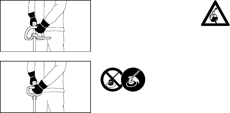
48
español / EE.UU
FS 75
Siempre sujete la orilladora firmemente
con ambas manos. Cierre firmemente
los dedos alrededor de los mangos,
manteniéndolos bien apoyados entre el
pulgar y dedo índice. Mantenga las
manos en esta posición, para que siem-
pre tenga la orilladora bien controlada.
Asegúrese que los mangos de la orilla-
dora y el mango de arranque están en
buenas condiciones y sin humedad,
resina, aceite o grasa.
!Advertencia
Nunca intente manejar ninguna orilla-
dora con una sola mano. La pérdida de
control de la orilladora puede ocasionar
lesiones graves o mortales.
!Advertencia
Para reducir el riesgo de sufrir lesiones
corporales debido a la pérdida de con-
trol y/o al contacto con la herramienta de
corte, asegúrese que su máquina está
equipada con el mango y arnés correc-
tos para el tipo de accesorio de corte
que está usando.
!Advertencia
Para reducir el
riesgo de lesiones
causadas por
objetos arrojados
y contacto con la
cuchilla, nunca maneje la orilladora sin
que tenga instalado debidamente el
deflector. Mantenga siempre el deflector
(y la faldilla en su caso) bien ajustado
(vea en su manual del usuario el capí-
tulo sobre montaje de las diversas
herramientas de corte). No trate de
alcanzar más lejos de lo debido. Man-
tenga los pies bien apoyados y equili-
brados en todo momento. Se debe tener
cuidado especial cuando las condicio-
nes del suelo son resbaladizas (suelo
húmedo, nieve) y en terreno difícil y con
mucha vegetación. Para evitar trope-
zarse, esté atento a los obstáculos ocul-
tos tales como tocones, raíces y zanjas.
Sea precavido cuando trabaje en decli-
ves o terreno irregular.
Antes de cortar, inspec-
cione el área en busca de
piedras, vidrio, pedazos
de metal, basura u otros
objetos sólidos. El acce-
sorio de corte puede arro-
jar los objetos de esta clase.
!Advertencia
La orilladora normalmente se usa a nivel
del suelo con el accesorio de corte para-
lelo al suelo. El uso de la orilladora
sobre el nivel del suelo o con el acceso-
rio de corte perpendicular al suelo
puede incrementar el riesgo de lesiones,
dado que el accesorio de corte queda
casi totalmente expuesto y la orilladora
es más difícil de controlar. No use nunca
la orilladora para recortar setos.
No la maneje usando el bloqueo de ace-
lerador de arranque, pues no tendrá
control de la velocidad del motor. Vea la
sección en su manual del usuario sobre
el uso correcto del control deslizante.
Si la herramienta de corte o el deflector
se atasca o queda pegado, siempre
apague el motor y asegúrese que la
herramienta de corte está detenida
antes de limpiarla. Limpie el pasto, las
malezas, etc. de la herramienta de corte
en intervalos regulares.
002BA057 KN002BA056 KN

49FS 75
español / EE.UU
!Advertencia
Durante el corte, revise el apriete y la
condición de la herramienta de corte en
intervalos regulares. Si nota un cambio
en el comportamiento de la herramienta,
apague el motor inmediatamente, revise
el apriete de la tuerca que sujeta la
herramienta y busque si hay grietas y
daños en la herramienta de corte. Susti-
tuya las herramientas de corte inmedia-
tamente si están dañadas. Las herra-
mientas en esas condiciones pueden
romperse a alta velocidad y causar
lesiones graves o mortales.
!Advertencia
Mantenga las manos y los
pies lejos de la herra-
mienta de corte. No toque
nunca con las manos o
cualquier parte del cuerpo
una herramienta de corte
que está girando. La herramienta sigue
girando por un rato después que se
suelta el gatillo de aceleración (efecto
de volante).
Ajustes importantes
!Advertencia
Para reducir el riesgo de lesiones perso-
nales debido a la pérdida de control o al
contacto con la herramienta de corte en
movimiento, no use una herramienta
cuyo ralentí está mal regulado. Cuando
el ralentí está correctamente regulado,
la herramienta de corte no debe girar.
Para instrucciones de ajuste del ralentí,
vea la sección correspondiente en el
manual del usuario.
Si no puede regular correctamente el
ralentí, pida a su concesionario STIHL
que revise la orilladora y haga los ajus-
tes o reparaciones correspondientes.
MANTENIMIENTO, REPARACION
Y ALMACENAMIENTO
Los trabajos de mantenimiento,
reemplazo o reparación de los dispo-
sitivos y sistemas de control de emi-
siones de escape pueden ser realiza-
dos por cualquier taller o técnico de
motores no diseñados para vehícu-
los. Sin embargo, si usted está recla-
mando servicio de garantía para
algún componente que no ha sido
reparado o mantenido debidamente,
o cuando se utilizan repuestos no
autorizados, STIHL puede denegar la
garantía.
!Advertencia
Utilice solamente piezas de repuesto de
STIHL para el mantenimiento y repara-
ción. El uso de piezas no fabricadas por
STIHL puede causar lesiones graves o
mortales.
Siga las instrucciones de mantenimiento
y reparación dadas en la sección corres-
pondiente del manual del usuario. Con-
sulte la tabla de mantenimiento en las
últimas páginas de este manual.
!Advertencia
Siempre apague el motor y asegúrese
que la herramienta de corte está dete-
nida antes de hacer cualquier trabajo de
mantenimiento o reparación o limpieza
de la orilladora. No intente hacer ningún
trabajo de mantenimiento o reparación
que no esté descrito en su manual del
usuario. Este tipo de trabajo debe reali-
zarse únicamente en el taller de servicio
de STIHL.
50
español / EE.UU
FS 75
!Advertencia
Nunca repare las herramientas de corte
dañadas aplicándoles soldadura, ende-
rezándolas o modificándoles su forma.
Esto puede causar el desprendimiento
de alguna pieza de la herramienta de
corte y producir lesiones graves o mor-
tales.
!Advertencia
Revise la condición de la herramienta de
corte en intervalos cortos regulares. Si
nota algún cambio en el comporta-
miento de la herramienta, revise inme-
diatamente el apriete y busque señales
de agrietamiento. Sustituya las herra-
mientas de corte dañadas o desafiladas
inmediatamente, incluso si tienen sólo
alguna grieta superficial. Si la herra-
mienta se afloja después de haber sido
debidamente apretada, la tuerca de
retención puede estar desgastada o
dañada y es necesario reemplazarla. Si
la herramienta continúa floja, consulte al
concesionario STIHL.
!Advertencia
Para reducir el riesgo de incendio y de
quemaduras, revise si hay fugas en la
tapa de llenado de combustible en inter-
valos regulares. Use la bujía especifi-
cada y asegúrese de que ella y el cable
de encendido están limpios y en buen
estado.
!Advertencia
No pruebe nunca el sistema de encen-
dido con el cable de encendido desco-
nectado de la bujía, o sin tener bien ins-
talada la bujía, ya que las chispas al
descubierto pueden causar un incendio.
!Advertencia
Para reducir el riesgo de incendio y de
quemaduras, utilice solamente las
bujías autorizadas por STIHL. Siempre
inserte el manguito de la bujía bien apre-
tado en el borne de la bujía del tamaño
adecuado. (Nota: Si el borne tiene una
tuerca adaptadora SAE desmontable,
tiene que ser instalada.) Una conexión
suelta entre el borne de la bujía y el
conector del cable de encendido en el
manguito puede crear un arco voltaico y
encender los vapores del combustible y
provocar un incendio. Mantenga la bujía
limpia, y asegúrese que el conductor de
encendido esté en buen estado.
!Advertencia
No maneje nunca su orilladora si el
silenciador está dañado, se ha perdido o
si fue modificado. Un silenciador mal
cuidado aumenta el riesgo de incendio y
puede causar pérdida del oído. No
toque nunca un silenciador caliente,
puede quemarse. Si el silenciador está
equipado con un chispero para reducir
el riesgo de incendio, no maneje nunca
su orilladora si le falta el chispero o está
dañado. No modifique ni retire ninguna
pieza del silenciador o chispero.
Recuerde que el riesgo de incendios
forestales es mayor durante las estacio-
nes calurosas y secas.
Apriete todas las tuercas, pernos y torni-
llos, excepto los tornillos de ajuste del
carburador, después de cada uso.
Además, es imprescindible seguir el
programa de mantenimiento diario indi-
cado en el manual del usuario de la ori-
lladora STIHL.
Para todo trabajo de mantenimiento, sír-
vase consultar la tabla de manteni-
miento y la declaración de garantía
que se encuentra al final de este
manual.
Guarde la orilladora en un lugar seco,
elevado o con llave lejos del alcance de
los niños.
Antes de guardar la máquina durante un
período de más de algunos días, siem-
pre vacíe el tanque de combustible.
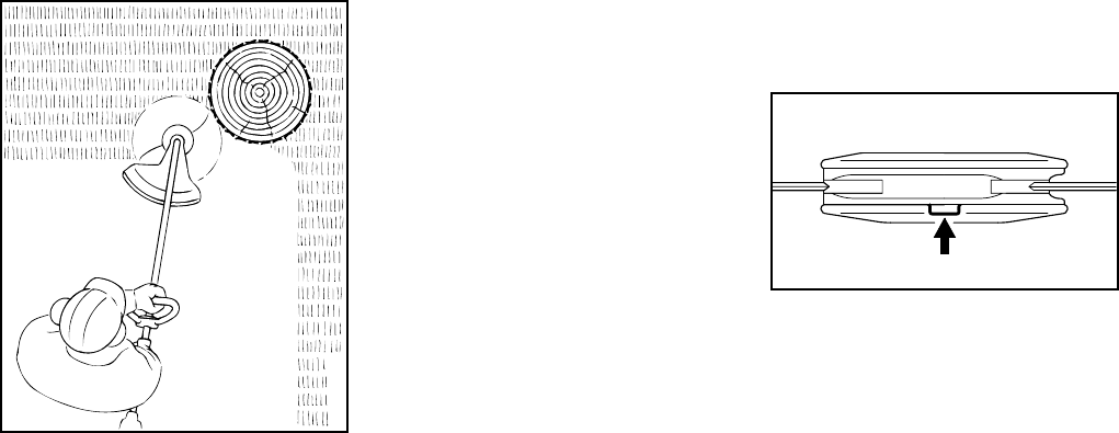
51FS 75
español / EE.UU
USO DE LAS HERRAMIENTAS DE
CORTE
Para una ilustración de las diversas
herramientas de corte y las instruccio-
nes sobre el montaje correcto, vea el
capítulo sobre "Montaje de la cabeza
segadora" en su manual del usuario.
Uso de las cabezas segadoras
Las cabezas segadoras AutoCut y
PolyCut de STIHL producen una termi-
nación limpia y ordenada.
Se usan solamente en las orilladoras
equipadas con una cuchilla limitadora
en el deflector para poder mantener el
hilo al largo correcto (vea el capítulo
"Piezas y controles" en este manual).
Si las orillas del césped tienen árboles o
están bordeadas por un cerco, etc., es
mejor usar el cabezal de hilo de nilón.
Este hilo deja un corte más "suave" con
menos riesgo de dañar la corteza de los
árboles, etc., que si se usan cuchillas de
polímero.
Sin embargo, las cabezas PolyCut de
STIHL con cuchilla de polímero produ-
cen un mejor corte si no hay plantas a lo
largo de la orilla del césped. No es nece-
sario afilar y las cuchillas de corte des-
gastadas se pueden cambiar fácilmente.
!Advertencia
Para reducir el riesgo de lesiones gra-
ves, nunca use un hilo de alambre o
reforzado con metal ni ningún otro mate-
rial en lugar de los hilos de corte de
nilón. Es posible que unos pedazos de
alambre sean desprendidos y arrojados
a gran velocidad contra el operador o
terceros.
Cabeza segadora "AutoCut" de
STIHL
El hilo de corte de nilón avanza automá-
ticamente cuando se le golpea contra el
suelo.
Cabeza segadora "PolyCut" de STIHL
Utiliza hilos de nilón o cuchillas de plás-
tico no rígidas.
Importante
En la base (periferia) de la Polycut 10-3
hay tres marcas rectangulares de límite
de desgaste. Para reducir el riesgo de
lesiones graves causadas por la rotura
de la cabeza o de las cuchillas, la
Polycut no debe ser utilizada cuando se
ha desgastado hasta una de estas mar-
cas. ¡Es importante seguir las instruccio-
nes para el mantenimiento suministra-
das con la cabeza segadora!
000BA019 KN
002BA177 KN
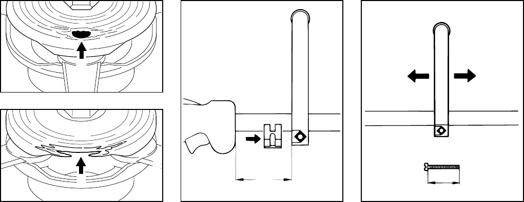
52
español / EE.UU
FS 75
!Advertencia
Se han incorporado marcas de límite de
desgaste en la base de la cabeza
PolyCut.
No utilice la cabeza PolyCut 5-3 si uno
de los agujeros circulares (1) empieza a
hacerse visible o si el reborde saliente
(2) se ha desgastado porque la herra-
mienta de corte podría romperse y los
objetos lanzados en consecuencia
podrían causar lesiones al operador o a
terceros.
:Fije el mango tórico (1) en el tubo de
mando, a aproximadamente 15 cm
(5,9 pulg) delante del mango de
control (2).
:Coloque la abrazadera (3) contra el
tubo de mando y deslícela hacia el
mango tórico.
:Inserte la tuerca cuadrada (4) en el
mango tórico.
:Coloque el tornillo de fijación (5) por
el otro lado y apriételo bien firme.
Ajuste del mango tórico a la posi-
ción más cómoda
:Suelte el tornillo de fijación (5).
:Deslice el mango tórico a lo largo
del tubo de mando, según se
requiera.
:Vuelva a apretar el tornillo de fija-
ción.
1
002BA073 KN
2
002BA074 KN
Montaje del mango tórico
3
355BA030 KN
1
2
A
343BA023 KN
5
4
50 mm
( 2" )
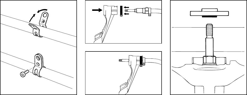
53FS 75
español / EE.UU
:Para la posición de la argolla de
transporte consulte la sección
"Piezas y controles"
:Coloque la abrazadera (1) con el
agujero roscado hacia el lado
izquierdo del tubo de mando.
:Apriete juntos los dos extremos de
la abrazadera y sosténgala en esa
posición.
:Inserte el tornillo M6 x 14 (2).
:Alinee la argolla de transporte.
:Apriete el tornillo firmemente.
* vea “Guía para el uso de este
manual”
:Deslice la abrazadera (1) por
encima del deflector (2).
:Empuje el deflector con la abraza-
dera sobre la caja del cojinete (3)
hasta el tope.
:Apriete la abrazadera.
Preparaciones
:Apoye la orilladora en el suelo sobre
su parte trasera con el eje (2) vuelto
hacia arriba.
“AutoCut 11-2” de STIHL
:Quite la placa de empuje (1) del eje
(2).
“PolyCut” de STIHL
:Coloque la placa de empuje (1) en
el eje (2) de modo que la parte
hexagonal interna (3) se engrane
en el hexágono (4).
Colocación de la argolla de
transporte*
002BA142 KN
1
2
1
Montaje del deflector
342BA045 KN
1
23
342BA002 KN
Montaje de las herramientas
de corte
342BA020 KN
1
2
3
4

54
español / EE.UU
FS 75
Bloqueo del eje impulsor
:Inserte el pasador de tope (1) en las
cavidades (2) del deflector y de la
placa de empuje. Gire la placa de
empuje en uno y otro sentido hasta
que el pasador de tope se inserte en
su posición y bloquee el eje.
Montaje de la cabeza segadora
Guarde la hoja de instrucciones de
la cabeza segadora en un lugar
seguro.
Armado de la AutoCut 11-2 de STIHL
:Inserte el resorte (1) en la caja del
carrete (2).
:Enrolle los hilos de nilón en el
carrete. Vea "Sustitución del hilo de
nilón".
:Arme la cabeza segadora. Vea
"Sustitución del hilo de nilón"
:Deslice la cabeza segadora (2) por
encima del eje (3) y engrane el
rebajo hexagonal (4) en el hexá-
gono externo (5).
:Coloque la tapa (6) en la cabeza
segadora y atorníllela en sentido
horario en el eje hasta donde tope.
Apriétela bien firme.
342BA021 KN
1
2
2
1
681BA014 KN
2
4
3
6
2
5
681BA015 KN
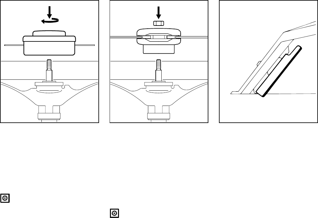
55FS 75
español / EE.UU
PolyCut 10-3 de STIHL
:Atornille la cabeza segadora (7) en
sentido horario en el eje (3) hasta
donde tope.
:Utilice el pasador de tope para blo-
quear el eje.
:Apriete la cabeza segadora bien
firme.
Quite el pasador de tope.
"PolyCut 5-3" de STIHL
Inserte la tuerca (8) en la cabeza
segadora.
Atornille la cabeza segadora (7) en
sentido horario en el eje (3) hasta
donde tope.
:Bloquee el eje.
:Apriete la cabeza segadora bien
firme.
Quite el pasador de tope.
Ajuste del hilo de nilón
AutoCut 11-2 de STIHL
:Sujete la cabeza segadora horizon-
tal al suelo mientras está girando,
golpéela contra el suelo, y avanza-
rán aproximadamente 3 cm / 1-1/4
pulg de hilo nuevo.
:La cuchilla (1) en el deflector (2)
corta el hilo sobrante al largo
correcto. Evite golpear la cabeza
segadora más de una vez.
3
7
681BA016 KN
3
7
8
681BA017 KN
342BA024 KN
1
2

56
español / EE.UU
FS 75
El hilo se alimenta únicamente si
los dos hilos miden por lo menos
2,5 cm (1 pulg) de largo.
PolyCut 10-3 de STIHL
Consulte las instrucciones que se sumi-
nistran con la cabeza segadora.
Retiro de la cabeza segadora
:Bloquee el eje.
:Destornille la cabeza segadora en
sentido contrahorario.
Sustitución del hilo de corte
AutoCut
Vea el capítulo "Sustitución del hilo de
nilón".
PolyCut 10-3
Consulte las instrucciones que se sumi-
nistran con la cabeza segadora.
Sustitución de cuchillas de ter-
moplástico
PolyCut
Siga las instrucciones que se suminis-
tran con la cabeza segadora.
Este motor está certificado para funcio-
nar con una mezcla de 50 a 1 de gaso-
lina sin plomo y aceite STIHL para moto-
res de dos tiempos.
Su motor de dos tiempos requiere una
mezcla de gasolina de calidad y aceite
de calidad para motores de dos tiempos
enfriados por aire.
Use gasolina sin plomo regular con un
octanaje mínimo de 89 (R+M/2). Si el
octanaje de la gasolina regular en su
zona es más bajo, use combustible sin
plomo superior.
El combustible de octanaje bajo puede
aumentar la temperatura de funciona-
miento del motor. Esto, a su vez,
aumenta el riesgo de que se agarrote el
pistón y se dañe el motor.
La composición química del combusti-
ble también es importante. Algunos adi-
tivos de combustible no solamente tie-
nen efectos perjudiciales en los
elastómeros (diafragmas de carburador,
sellos de aceite, tuberías de combusti-
ble, etc.), sino también en las piezas
fundidas de magnesio y en los converti-
dores catalíticos. Esto podría causar
problemas de funcionamiento e incluso
daño del motor. Por esta razón, STIHL
recomienda el uso exclusivo de gasolina
sin plomo de buena calidad.
Use solamente el aceite STIHL para
motores de dos tiempos o un aceite de
marca equivalente para motores de dos
tiempos diseñado para usar exclusiva-
mente con los motores de dos tiempos
enfriados por aire.
Recomendamos el aceite STIHL para
motores de dos tiempos 50:1 pues está
especialmente formulado para usarse
en motores STIHL.
No use aceites para mezclar con desig-
naciones BIA o TCW (para motores de
dos tiempos enfriados por agua) ni otros
aceites para mezclar diseñados para
usar en motores enfriados por agua o
por aire (por ejemplo, para motores
marinos fuera de borda, motonieves,
sierras de cadenas, bicimotos, etc.).
Manipule la gasolina con sumo cuidado.
Evite el contacto directo con la piel y
evite inhalar los vapores de combusti-
ble. Cuando se reabastece de combus-
tible, quite primero el envase del vehí-
culo y colóquelo en el suelo antes de
llenarlo. No llene un envase que está en
un vehículo o apoyado sobre el mismo.
Mantenga el envase bien cerrado para
evitar la entrada de humedad a la mez-
cla.
Según sea necesario, limpie el tanque
de combustible de la máquina y el
envase en que se guarda la mezcla de
combustible.
Combustible
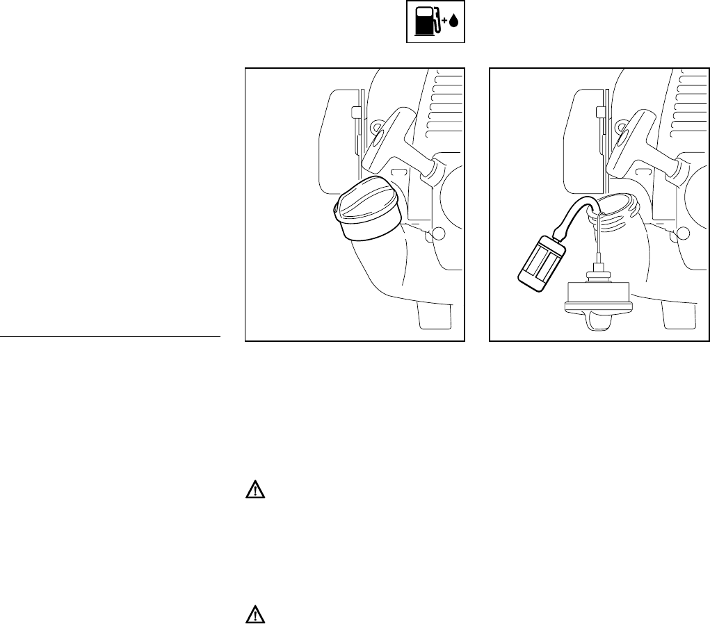
57FS 75
español / EE.UU
Duración de la mezcla de combusti-
ble
Mezcle una cantidad suficiente de com-
bustible para trabajar unos pocos días,
no lo guarde por más de 3 meses. Guár-
delo únicamente en envases aprobados
para combustible. Para el proceso de
mezclado, vierta el aceite en el envase
primero y luego agregue la gasolina.
Cierre el envase y agítelo vigorosa-
mente a mano para asegurar que se
mezclen bien el aceite y la gasolina.
Deseche los envases vacíos usados
para mezclar el aceite únicamente en
vertederos autorizados para ello.
Antes de llenar la máquina con combus-
tible, limpie a fondo la tapa de llenado y
la zona alrededor del mismo para evitar
la entrada de tierra al tanque.
Siempre agite la mezcla vigorosamente
en el recipiente antes de llenar la
máquina con combustible.
Para reducir el riesgo de quemaduras,
así como otras lesiones corporales
ocasionadas por los escapes de vapor
de gasolina y otras emanaciones,
quite la tapa de llenado de combustible
cuidadosamente de modo que la pre-
sión que se pueda haber acumulado
en el tanque se disipe lentamente.
Después de haber llenado la
máquina con combustible, apriete la
tapa del tanque tan firmemente
como sea posible con la mano.
Cambie el recogedor de combus-
tible una vez al año.
Antes de almacenar la máquina por un
período prolongado, vacíe y limpie el
tanque de combustible y ponga el motor
en marcha hasta que se seque el com-
bustible del carburador.
Gaso-
lina
Aceite (STIHL 50:1 ó aceite
de calidad equivalente)
gal
EE.UU.
oz fl
EE.UU.
12.6
2 1/2 6.4
512.8
Llenado de com-
bustible
389BA031 KN
389BA032 KN
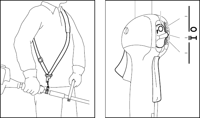
58
español / EE.UU
FS 75
Correa para el hombro*
:Colóquese la correa (1) sobre el
hombro.
:Con la cortadora de matorrales
conectada, regule el largo de la
correa hasta que el gancho de
resorte (2) esté a una distancia más
o menos igual al ancho de la mano
por debajo de la cadera derecha.
*vea “Guía para el uso de este
manual”
Controles
Bloqueo del gatillo de aceleración(1)
Gatillo de aceleración (2)
Control deslizante (3)
Posiciones del control deslizante
STOP -O (4) – motor apagado – el
encendido está desconectado
# – posición de funcionamiento normal
(5) – el motor está en marcha o puede
arrancarse
START (6) – el encendido está conec-
tado y es posible arrancar el motor
Símbolo en el control deslizante
h (7) – símbolo de parada y flecha –
para apagar el motor, empuje el control
deslizante en el sentido de la flecha en
el símbolo de parada (h) a STOP-O.
Arranque
:Mantenga oprimido el bloqueo del
gatillo y oprima el gatillo de acelera-
ción.
:Mientras sujeta las dos manivelas
en esta posición, mueva el control
deslizante a la posición de ARRAN-
QUE y sujételo allí.
:Ahora suelte el gatillo de acelera-
ción, el control deslizante y el blo-
queo del gatillo, en el orden indi-
cado. Esta es la posición de
arranque del acelerador.
Colocación del arnés
1
392BA039 KN
2
Arranque / parada del moto
r
3
STOP
2
5
6
4
7
002BA181 KN
START
STOP-
1
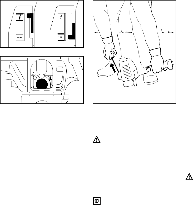
59FS 75
español / EE.UU
:Coloque la palanca del estrangula-
dor (8):
Para arranque en frío a g
Para arranque en caliente a e–
también utilice esta posición si el
motor ha estado en marcha, pero
aún está frío.
:Oprima el bulbo (9) de la bomba de
combustible por lo menos cinco
veces, aunque el bulbo esté lleno
de combustible.
:Apoye la máquina en el suelo:
deberá reposar de modo seguro
sobre la brida del motor y el deflec-
tor.
Verifique que la herramienta de
corte no esté tocando el suelo ni
ningún otro obstáculo.
:Asegúrese de tener los pies bien
apoyados.
:Sujete la máquina con la mano
izquierda en el mango de control y
empújela hacia abajo firmemente –
el pulgar debe estar debajo del
mango de control.
No se pare ni se arrodille sobre el
tubo de mando. Se podría dañar
permanentemente el tubo de
mando.
:Con la mano derecha tire lenta-
mente del mango de arranque hasta
que sienta una resistencia definitiva
y en seguida dele un tirón fuerte y
rápido.
No tire de la cuerda de arranque
totalmente hasta fuera, se podría
cortar.
:No deje que el mango de arranque
retroceda bruscamente; guíelo len-
tamente hacia el interior de la caja
de modo que la cuerda se enrolle
debidamente.
:Continúe haciendo girar el motor
hasta que arranque.
Cuando el motor empieza a encen-
derse:
:Ponga la palanca del estrangulador
en e
:Siga intentando el arranque.
Tan pronto arranque:
:Oprima el gatillo de aceleración
momentáneamente – el control des-
lizante se desplaza a la posición de
marcha #, y el motor regresa a ace-
leración de ralentí.
Asegúrese que el carburador esté
correctamente ajustado; la herra-
mienta de corte no debe girar
cuando el motor está funcionando a
ralentí.
La herramienta está lista para usarse.
393BA017 KN
8
8
393BA018 KN
9
355BA007 KN

60
español / EE.UU
FS 75
Para apagar el motor:
:Mueva el control deslizante en el
sentido indicado por la flecha (h) a
STOP-O.
Otros puntos a observarse
durante el arranque
A temperaturas ambiente muy bajas
Tan pronto arranque:
:Oprima el gatillo de aceleración
momentáneamente para desengra-
nar la posición de arranque del ace-
lerador - el control deslizante se
desplaza a la posición de marcha #,
y el motor regresa a aceleración de
ralentí.
:Deje que el motor se caliente por un
rato corto a aceleración parcial.
Si el motor no arranca
Si no se mueve la palanca del estrangu-
lador a e en un tiempo suficientemente
corto después que el motor ha empe-
zado a encenderse, la cámara de com-
bustión se encuentra "ahogada".
:Ponga la palanca del estrangulador
en e
:Ponga el control deslizante, la
palanca de bloqueo y el gatillo de
aceleración en la posición de arran-
que.
:Arranque el motor tirando de la
cuerda de arranque rápidamente,
pueden ser necesarios unos 10 a 20
tirones.
Si el motor todavía no arranca
:Mueva el control deslizante en el
sentido indicado por la flecha (h) a
STOP-O.
:Quite el casquillo de la bujía (10).
:Destornille y seque la bujía.
:Abra el acelerador al máximo.
:Haga girar el motor varias veces
con el arrancador para despejar la
cámara de combustión.
:Vuelva a instalar la bujía.
:Conecte el casquillo de la bujía
(empújelo firmemente).
:Mueva el control deslizante a la
posición START.
:Ponga la palanca del estrangulador
en e – aun si el motor está frío
:Ahora arranque el motor.
Ajuste del cable del acelerador
:Revise el ajuste del cable del acele-
rador – vea el capítulo "Ajuste del
cable del acelerador".
Se agotó el combustible en el tanque
:Después de llenar el tanque, oprima
el bulbo de la bomba de combusti-
ble por lo menos cinco veces, aun-
que el bulbo esté lleno de combusti-
ble.
:Ajuste la palanca del estrangulador
según la temperatura del motor.
:Ahora arranque el motor.
393BA019 KN
10

61FS 75
español / EE.UU
Durante el período de rodaje
Una máquina nueva no debe hacerse
funcionar a velocidad alta (aceleración
máxima sin carga) por el lapso que tome
llenar el tanque tres veces. Esto evita la
imposición de cargas innecesariamente
altas durante el período de rodaje.
Puesto que todas las piezas móviles
necesitan un período de rodaje, las
resistencias causadas por la fricción en
el motor son mayores durante este
período. El motor desarrolla su potencia
máxima después de haber llenado el
tanque de 5 a 15 veces.
Durante el funcionamiento
Después de un período largo de funcio-
namiento con el acelerador a fondo,
deje funcionar el motor por un rato en
ralentí de modo que el calor en el motor
sea disipado por la corriente de aire de
enfriamiento. Esto ayuda a evitar que
los componentes montados en el motor
(encendido, carburador) sufran sobre-
cargas térmicas.
Después de terminar el trabajo
Espere que el motor se enfríe. Vacíe el
tanque de combustible. Almacene la
máquina en un lugar seco. Revise el
apriete de las tuercas y tornillos (no los
tornillos de ajuste) periódicamente y
vuelva a apretar según sea necesario.
La suciedad en el filtro de aire reduce la
potencia del motor, aumenta el consumo
de combustible y dificulta el arranque
del motor.
Si se nota una pérdida considerable
de la potencia del motor
:Ponga la palanca del estrangulador
en g
:Oprima la lengüeta (1).
:Levante cuidadosamente la
cubierta (2) del filtro encima de la
lengüeta y quítela.
:Limpie toda la suciedad de alrede-
dor del filtro.
:Retire los elementos de espuma y
de fieltro del filtro.
:Lave el elemento de espuma en una
solución limpiadora limpia y no infla-
mable (por ejemplo, agua jabonosa
tibia) y séquelo.
:Coloque un elemento de fieltro
nuevo. Como una medida proviso-
ria, es posible limpiarlo golpeándolo
en la palma de la mano o soplán-
dolo con aire comprimido. No lo
lave.
Siempre sustituya las piezas daña-
das.
:Coloque el elemento de espuma (3)
en la cubierta (2) del filtro.
:Coloque el elemento de fieltro (4)
(las marcas orientadas hacia aden-
tro) en la caja del filtro (5).
:Coloque la tapa del filtro de modo
que se trabe en su lugar.
Instrucciones de manejo Limpieza del filtro de aire
355BA014 KN
2
1
23
355BA031 KN
45
355BA032 KN

62
español / EE.UU
FS 75
Las emisiones de gases de escape son
controladas por el diseño de parámetros
y componentes fundamentales del
motor (por ej. carburación, encendido,
regulación y regulación de la válvula o
lumbrera) sin la adición de ningún
equipo importante.
El carburador se ajusta en la fábrica.
Este ajuste provee una mezcla óptima
de combustible y aire bajo la mayoría de
las condiciones de funcionamiento.
Con este carburador es posible ajustar
la velocidad de ralentí del motor dentro
de una gama pequeña.
Ajuste normal
:Apague el motor.
:Monte una cabeza segadora apro-
bada
:Revise el filtro de aire y sustitúyalo
si es necesario.
:Revise el chispero * y límpielo o ins-
tale uno nuevo de ser necesario.
:Gire el tornillo de ajuste de veloci-
dad alta (H) en sentido contrahora-
rio hasta su tope (no más de 3/4 de
vuelta).
:Atornille el tornillo de velocidad baja
(L) hasta que tope en su asiento.
Después ábralo una vuelta en sen-
tido contrahorario.
:Arranque el motor y caliéntelo.
:Ajuste la velocidad de ralentí con el
tornillo (LA) hasta que la cabeza
segadora deje de girar.
Ajustes finos
Puede ser necesario efectuar un ajuste
ligero del tornillo de velocidad alta (H) si
la potencia del motor no es adecuada
para trabajar en grandes altitudes o al
nivel del mar.
* vea “Guía para el uso de este
manual”
Manejo del motor Ajuste del carburador
265BA024 KN
LA
HL
1
3 / 4

63FS 75
español / EE.UU
Regla general
Gire el tornillo de ajuste de veloci-
dad alta (H) aproximadamente 1/4
de vuelta por cada 1000 metros
(3300 pies) de cambio de altura.
Condiciones para ajuste
Compruebe que los hilos de corte
tengan longitud máxima (es decir,
llegan hasta la cuchilla limitadora en
el deflector).
:Lleve a cabo el ajuste normal.
:Caliente el motor por aproximada-
mente 3 minutos.
:Abra el acelerador al máximo.
En alturas grandes
:Gire el tornillo de alta velocidad (H)
en sentido horario (mezcla más
pobre), pero no más allá del tope,
hasta que no haya un aumento
notable de velocidad del motor.
Al nivel del mar
:Gire el tornillo de alta velocidad (H)
en sentido contrahorario (mezcla
más rica), pero no más allá del tope,
hasta que no haya un aumento
notable de velocidad del motor.
Es posible que se alcance la veloci-
dad máxima del motor con el ajuste
normal en cada caso.
Ajuste de ralentí
Generalmente es necesario cambiar el
ajuste del tornillo de ralentí (LA) des-
pués de cada corrección hecha al torni-
llo de velocidad baja (L).
:Caliente el motor por aproximada-
mente 3 minutos.
El motor se para durante el funciona-
miento a ralentí
:Gire lentamente el tornillo de ajuste
de ralentí (LA) en sentido horario
hasta que el motor funcione de
modo suave – la cabeza segadora
no debe girar.
La cabeza segadora gira cuando el
motor funciona a ralentí
:Gire el tornillo de ralentí (LA) lenta-
mente en sentido contrahorario
hasta que la cuchilla se detenga y
luego gire el tornillo aproximada-
mente otra media vuelta a vuelta
completa en el mismo sentido.
Funcionamiento irregular a ralentí, el
motor se para aunque se ha corre-
gido el ajuste del tornillo LA, acelera-
ción inadecuada
Ajuste de ralentí con mezcla muy
pobre:
:Gire el tornillo de velocidad baja (L)
en sentido contrahorario (aprox. 1/4
de vuelta) hasta que el motor fun-
cione y se acelere de modo uni-
forme.
Funcionamiento irregular a ralentí
Ajuste de ralentí con mezcla muy
rica:
:Gire el tornillo de velocidad baja (L)
en sentido horario (aprox. 1/4 de
vuelta) hasta que el motor funcione
y se acelere de modo uniforme.

64
español / EE.UU
FS 75
Si el motor pierde potencia, revise el
chispero del silenciador.
:Levante el chispero y sáquelo de
lado.
:Limpie el chispero, de ser necesa-
rio.
:Si el chispero está dañado u obs-
truido, instale uno nuevo.
:Vuelva a instalar el chispero.
* vea "Guía para el uso de este
manual"
La mezcla de combustible incorrecta
(demasiado aceite de motor en la gaso-
lina), el filtro de aire sucio y condiciones
de funcionamiento desfavorables (gene-
ralmente a media aceleración, etc.)
afectan la condición de la bujía. Estos
factores causan la formación de depósi-
tos en la punta del aislador lo que puede
dificultar el funcionamiento.
Si el motor tiene poca potencia, le
cuesta arrancar o funciona deficiente-
mente a velocidad de ralentí, primero
revise la bujía.
:Saque la bujía – vea „Arranque /
parada del motor“.
:Limpie la bujía sucia.
:Mida la separación entre electrodos
de la bujía (A). Vuelva a ajustar si es
necesario. Vea “Especificaciones”.
:Use únicamente bujías de tipo
resistencia de capacidad aprobada.
Corrija la causa de la suciedad de la
bujía:
:Demasiado aceite en la mezcla de
combustible.
:Filtro de aire sucio.
:Condiciones de funcionamiento
desfavorables, por ej., funciona-
miento a media aceleración.
Coloque una bujía nueva después de
100 horas de funcionamiento, aproxi-
madamente, o más temprano si nota
que los electrodos están muy desgasta-
dos.
Chispero* en silenciador
392BA035 KN
Revisión de la bujía
000BA002 KN
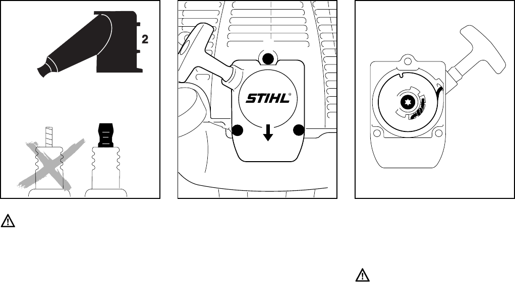
65FS 75
español / EE.UU
Para reducir el riesgo de incendios y
lesiones por quemadura, use sola-
mente bujías autorizadas por
STIHL. Siempre encaje un casquillo
(2) del tamaño correcto bien ajus-
tado en el borne (1) de la bujía.
(Nota: Si el borne tiene una tuerca
adaptadora SAE desprendible,
colóquela.) Una conexión suelta
entre el casquillo de la bujía y el
conector del alambre de encendido
puede formar un arco eléctrico,
inflamar los vapores combustibles y
finalmente causar un incendio.
Retiro de la tapa del arrancador
:Saque los tornillos (1).
:Levante la tapa (2) de encima del
tanque (3) y extraígala de debajo de
la cubierta protectora (4).
Retiro del rotor de la cuerda
:Saque el tornillo (5).
:Retire el rotor de la cuerda con
mucho cuidado.
El resorte de rebobinado está alo-
jado en el rotor y puede saltar y des-
enrollarse si no se procede con cui-
dado.
Las piezas del resorte roto pueden
estar tensadas y pueden lanzarse
inesperadamente cuando que quita
el rotor de la cuerda. Para reducir el
riesgo de lesionarse, póngase
guantes y protector facial.
000BA036 TR
1
Sustitución de la cuerda de
arranque y resorte de rebo-
binado
1
11
2
3
4
392BA013 KN
5
392BA014 KN
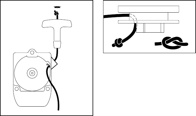
66
español / EE.UU
FS 75
Sustitución de la cuerda de arran-
que
:Utilice un destornillador para apa-
lancar la tapa†(6) fuera del mango
de arranque.
:Retire la cuerda restante del rotor y
del mango, asegurándose de evitar
que el manguito ElastoStart se
salga del mango.
:Haga un nudo de rizo sencillo en el
extremo de la cuerda de arranque
nueva (vea Especificaciones) y des-
pués pase la cuerda por la parte
superior del mango y por el buje de
la cuerda (7).
:Vuelva a instalar la tapa en el
mango.
:Tire de la cuerda a través del rotor y
fíjela con un nudo de rizo simple.
:Pase a la sección "Instalación del
rotor de la cuerda".
Sustitución del resorte de rebobi-
nado roto
Se puede conseguir de la fábrica dos
tipos de resorte de repuesto:
– Un resorte de rebobinado listo para
instalar fijado con un alambre rete-
nedor.
– Un rotor de la cuerda con un resorte
de rebobinado ya instalado.
Instalación del resorte de rebobinado
listo para instalar
:Lubrique el resorte con algunas
gotas de aceite sin resina -- vea
"Accesorios especiales" -- ¡no abra
el alambre retenedor!
:Quite cuidadosamente las piezas
del resorte viejo de la tapa del
arrancador y del rotor de la cuerda.
:Introduzca el resorte de rebobinado
nuevo en el rotor de la cuerda y, al
mismo tiempo, coloque la espiral
exterior del resorte en la hendidura
del rotor – el alambre retenedor se
suelta durante este proceso.
Si el resorte se sale y se desenrolla,
colóquelo nuevamente en sentido
contrahorario, empezando en el
exterior y avanzando hacia adentro.
:Pase a la sección "Instalación del
rotor de la cuerda".
Instalación del rotor de la cuerda con
resorte de rebobinado
:Retire cuidadosamente del emba-
laje el nuevo rotor con resorte de
rebobinado. El resorte de rebobi-
nado puede saltarse si no se pro-
cede con cuidado –riesgo de lesio-
nes.
:Lubrique el resorte con algunas
gotas de aceite sin resina -- vea
"Accesorios especiales".
:Pase a la sección "Instalación del
rotor de la cuerda".
6
7
392BA015 KN
392BA024 KN
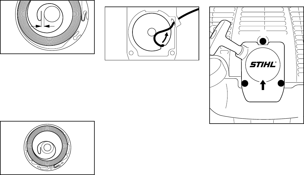
67FS 75
español / EE.UU
Instalación del rotor de la cuerda
:Compruebe la dimensión a de la
espiral interior del resorte y doble el
resorte ligeramente, de ser necesa-
rio.
:Cubra la cavidad del cojinete del
rotor de la cuerda con aceite sin
resina – vea "Accesorios especia-
les".
:Deslice el rotor en el poste del
arrancador–
gírelo hacia uno y otro lado para
engranar la espiral terminal d(8) del
resorte de rebobinado.
:Inserte el tornillo (5) y apriételo bien
firme.
:Pase a "Tensado del resorte de
rebobinado".
Tensado del resorte de rebobi-
nado
:Forme un bucle con la cuerda de
arranque sin envolver y utilícelo
para girar el rotor seis revoluciones
completas en sentido contrahorario.
Sostenga el rotor inmóvil – ende-
rece la cuerda – suelte el rotor –
suelte la cuerda lentamente de
modo que se enrolle en el rotor.
:Revise la tensión del resorte:
– El mango de arranque debe quedar
firmemente sentado en el buje guía
de la cuerda.
Si el mango cae hacia un lado: Dele
una vuelta adicional al rotor de la
cuerda para aumentar la tensión del
resorte.
– Cuando la cuerda de arranque se
extiende completamente, debe ser
posible girar el rotor media vuelta
adicional. En caso contrario, el
resorte está sobretensado y podría
romperse. Quítele una vuelta de la
cuerda al rotor.
:Pase a "Instalación de la tapa del
arrancador".
Instalación de la tapa del arranca-
dor
:Empuje el reborde de montaje
superior (2) debajo de la envuelta
(4) –
alinee el tanque (3) y empuje la
parte inferior de la tapa sobre el tan-
que
:Inserte y apriete los tornillos (1) de
la caja.
a
389BA029 KN
a = 2mm
(0.08 in)
8
392BA025 KN
392BA044 KN
1
11
2
3
4
393BA045 KN
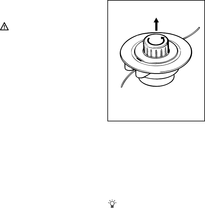
68
español / EE.UU
FS 75
Para intervalos de 3 meses o más
:Vacíe y limpie el tanque de combus-
tible en una zona bien ventilada.
:Haga funcionar el motor hasta que
el carburador se seque – esto
ayuda a evitar que los diafragmas
del carburador se peguen.
:Retire, limpie e inspeccione el acce-
sorio de corte.
:Limpie la máquina a fondo - preste
atención especial a las aletas del
cilindro y al filtro de aire.
:Guarde la máquina en un lugar seco
y elevado, o bajo llave – fuera del
alcance de los niños y de otras per-
sonas no autorizadas.
:Deseche apropiadamente los resi-
duos del combustible y la solución
de limpieza de acuerdo con los
requerimientos locales de protec-
ción del ambiente.
Inspeccione siempre la cabeza sega-
dora en busca de desgaste antes de
colocar el hilo de nilón de repuesto.
Si hay señales de desgaste serio,
podría ser necesario sustituir algu-
nas piezas o la cabeza segadora
completa.
Preparaciones
:Apague el motor.
:Apoye la cortadora de matorrales
en el suelo sobre su parte trasera
con la cabeza segadora vuelta
hacia arriba.
Retiro del hilo de nilón restante
:Abra la cabeza segadora. Para
hacerlo, sujete la cabeza segadora
inmóvil y gire la tapa (1) en sentido
contrahorario.
:Desenganche el carrete (2),
sáquelo de la cabeza segadora y
retire el hilo de nilón restante.
Enrollado del hilo en el carrete
Se puede instalar un carrete pre-
enrollado** para ahorrarse el proce-
dimiento siguiente.
** vea "Accesorios especiales"
Almacenamiento de la
máquina
Sustitución del hilo de nilón
AutoCut 11-2 de STIHL
681BA008 KN
1
2

69FS 75
español / EE.UU
:Use hilo de nilón codificado verde
de 2 mm (0,080 pulg) de diámetro.
:Corte del carrete dos trozos de hilo
de nilón de 3 m (10 pies) de largo**.
:Inserte el extremo de cada hilo (3)
en los agujeros (4) en el carrete.
:Doble los extremos de los hilos por
encima del borde de los agujeros
para formar un gancho.
** vea "Accesorios especiales"
:Enderece los hilos de nilón y enról-
lelos bien apretados en el carrete -
un hilo en cada cámara.
:Enganche los extremos de los hilos
de nilón en las muescas (5).
Armado de la cabeza segadora
Verifique que el resorte de compre-
sión esté instalado (vea “Montaje de
la cabeza segadora”).
:Enhebre los extremos de los hilos
(6) en los manguitos (7) e inserte el
carrete (2) en la cabeza para que
encaje en su lugar.
Los hilos de nilón deben desengan-
charse de las muescas (5) cuando
se inserta el carrete en su lugar.
:Tire de los extremos de los hilos
hasta que paren.
:Instale la cabeza segadora en la
máquina.
681BA009 KN
4
3
3
681BA010 KN
5
5
7
681BA011 KN
2
6
6

70
español / EE.UU
FS 75
* vea “Guía para el uso de este manual”
Tabla de mantenimiento
Sírvase notar que los intervalos de mantenimiento siguientes son aplicables en
condiciones normales de funcionamiento. Si el tiempo de trabajo por jornada es
más largo que lo normal, o si las condiciones de corte son extremas (zonas polvo-
rientas, etc.), acorte los intervalos indicados de modo correspondiente.
antes de comenzar el trabajo
después de terminar el
trabajo o diariamente
después de cada parada
para cargar combustible
semanalmente
mensualmente
cada 12 meses
si hay problema
si tiene daños
según se requiera
Máquina completa
Inspección visual
(condición general, fugas) XX
Limpiar X
Mango de control Comprobar funcionamiento XX
Filtro de aire Limpiar XX
Reemplazar X
Recogedor en tanque de combustible Revisar X
Reemplazar XXX
Tanque de combustible Limpiar XX
Carburador
Comprobar el ajuste de ralentí, la
herramienta de corte no debe
girar
XX
Ajustar el ralentí X
Bujía Ajustar la distancia entre electro-
dos X
Entradas de enfriamiento Inspeccionar X
Limpiar X
Chispero en silenciador* Inspeccionar XX
Limpiar o reemplazar XX
Todos los tornillos y tuercas accesibles (salvo
los tornillos de ajuste) Volver a apretar X
Elemento antivibración Solicitar al concesionario STIHL
su reemplazo X
Herramienta de corte
Inspección visual XX
Reemplazar X
Comprobar el apriete de la herra-
mienta de corte XX

71FS 75
español / EE.UU
1 Mango tórico
2Control deslizante
3 Bloqueo del gatillo de aceleración
4 Gatillo de aceleración
5 Casquillo de bujía
6 Cubierta del filtro de aire
7Apoyo de la máquina
8 Argolla de transporte (abrazadera)*
# Número de serie
9 Tanque de combustible
10 Tapa de llenado de combustible
11 Mango de arranque
12 Bomba de combustible
13 Palanca del estrangulador
14 Tornillos de ajuste del carburador
15 Silenciador (con chispero*)
16 Deflector
17 Cuchilla limitadora del hilo
18 Cabeza segadora
* vea “Guía para el uso de este
manual”
Piezas y controles
2
392BA040 KN
1
3
4
5
6
7
#
8
10 9
11
12
13
14 15
392BA041 KN
17
392BA042 KN
18
16
72
español / EE.UU
FS 75
Definiciones
1. Mango tórico
Para facilitar el control de la
máquina durante el proceso de
corte.
2. Control deslizante
Para aceleración de arranque, mar-
cha y parada. Mantiene el acelera-
dor parcialmente abierto durante el
arranque, apaga el encendido del
motor y detiene su marcha.
3. Bloqueo del gatillo de acelera-
ción
Debe ser oprimido antes de poder
activar el gatillo de aceleración.
4. Gatillo de aceleración
Regula la velocidad del motor.
5. Casquillo de la bujía
Conecta la bujía al alambre de
encendido.
6. Cubierta del filtro de aire
Protege el filtro de aire.
7. Apoyo de la máquina
Para apoyar la máquina en el suelo.
8. Argolla de transporte (abraza-
dera)
Conecta la cortadora de matorrales
al arnés.
9. Tanque de combustible
Contiene la mezcla de gasolina y
aceite.
10. Tapa de llenado de combustible
Para tapar el tanque de combusti-
ble.
11. Mango de arranque
El mango de la cuerda de arranque,
el cual es el dispositivo usado para
arrancar el motor.
12. Bomba de combustible
Suministra alimentación adicional
de combustible para el arranque en
frío.
13. Palanca del estrangulador
Facilita el arranque del motor al
enriquecer la mezcla.
14. Tornillos de ajuste del carbura-
dor
Para afinar el carburador.
15. Silenciador (con chispero)
Reduce los ruidos del tubo de
escape y desvía los gases de
escape lejos del operador.
16. Deflector
Sirve para reducir el riesgo de lesio-
nes causadas por objetos extraños
arrojados contra el operador por la
herramienta de corte y por el con-
tacto con la herramienta de corte.
17. Cuchilla limitadora del hilo
Cuchilla que se monta en el deflec-
tor para recortar el hilo de nilón al
largo correcto.
18. Cabeza segadora
El accesorio de corte, que se usa
para diferentes propósitos (acceso-
rio especial).
73FS 75
español / EE.UU
Motor
EPA:
El período de cumplimiento de emisio-
nes indicado en la etiqueta de cumpli-
miento de emisiones es la cantidad de
horas de funcionamiento para la cual la
máquina ha demostrado la conformidad
con los requerimientos de emisiones del
Gobierno federal de los EE.UU.
Categoría A = 300 horas, B = 125 horas,
C = 50 horas
CARB:
El período de cumplimiento de emisio-
nes empleado en la etiqueta del índice
de aire CARB tiene las siguientes defini-
ciones:
Extended (extendido) = 300 horas
Intermediate (intermedio) = 125 horas
Moderate (moderado) = 50 horas
Sistema de encendido
Sistema de combustible
Arrancador de cuerda
Peso
* vea “Guía para el uso de este manual”
Motor de un cilindro, dos tiempos
Cilindrada: 25,4 cm3
(1,55 pulg3)
Diámetro: 34 mm
(1,34 pulg)
Carrera: 28 mm
(1,10 pulg)
Potencia según ISO
8893: 0,95 kW
(1.3 bhp)
Velocidad máx. de
eje de salida (mon-
taje de herramienta
de corte) 7500 rpm
Ralentí: 2800 rpm
Especificaciones
Tipo: Encendido por magneto electró-
nico
Bujía (extin-
guida):
Bosch WSR 6 F,
NGK BPMR 7 A o
Champion RCJ 6Y
Distancia entre
electrodos:
0,5 mm (0,02 pulg)
Roscas de la
bujía:
M 14 x 1.25;
9,5 mm (0,37 pulg)
de largo
Carburador: Carburador de diafragma
de todas posiciones con bomba de
combustible integral
Filtro de aire: Elementos de
espuma y de fiel-
tro
Capacidad del
tanque de combusti-
ble:
0,44 l
(0.93 pt EE.UU.)
Mezcla de combus-
tible:
Vea "Combusti-
ble"
Cuerda de arranque:
3,0 mm (0,12 pulg) de diámetro
Largo
800 mm (31,5 pulg)*
850 mm (33,5 pulg)*
sin herramienta de corte y
deflector 4,2 kg
(9,26 lb)
74
español / EE.UU
FS 75
Herramientas de corte
STIHL AutoCut 11-2
Hilos de nilón:
2,0 mm (0,080 pulg) de diámetro, verde,
varios longitudes
2,4 mm (0,095 pulg) de diámetro, ana-
ranjado,
varias longitudes
Carrete arrollado (con hilo de nilón)
STIHL PolyCut 5-3
Cuchillas de termoplástico (paquete de
12)
Placa de empuje
Pasador de bloqueo
Otros accesorios especiales
Anteojos de seguridad
Correa para hombro
Llave combinada
Placa de empuje
ElastoStart de STIHL (cuerda de arran-
que con mango)
Aceite lubricante especial libre de resi-
nas
frasco de 100 ml (3,4 oz. fl.)
Póngase en contacto con el concesiona-
rio STIHL para obtener la información
más reciente sobre éstos y otros acce-
sorios especiales.
El usuario de esta máquina deberá rea-
lizar solamente los trabajos de manteni-
miento descritos en este manual. Otros
trabajos de reparación debe hacerlos
solamente un técnico de servicio autori-
zado por STIHL.
Los reclamos de garantía serán acepta-
dos únicamente si la reparación fue
hecha por un concesionario de servicio
autorizado por STIHL usando repuestos
originales de STIHL.
Los repuestos originales de STIHL se
pueden identificar por el número de
pieza de STIHL, el logotipo
STIHl
y el símbolo de piezas de STIHL(
En las piezas pequeñas, el símbolo
puede aparecer solo.
Accesorios especiales Mantenimiento y reparación
75FS 75
español / EE.UU
Sus derechos y obligaciones de
garantía
La Agencia de Protección del Medio
Ambiente (EPA) de los EE.UU., el Con-
sejo de Recursos del Aire del Estado de
California (CARB) y STIHL Incorporated
se complacen en explicarle la garantía
del sistema de control de emisiones ins-
talado en el motor de su equipo de
modelos año 2000 y siguientes. En Cali-
fornia, los nuevos motores pequeños
para uso fuera de carretera deben estar
diseñados, construidos y equipados de
conformidad con las rigurosas normas
de contaminación del aire del estado. En
otros estados, los modelos 1997 y pos-
teriores de tales motores deben estar
diseñados, construidos y equipados, al
tiempo de la venta, de conformidad con
los reglamentos correspondientes de la
EPA. El motor debe carecer de defectos
en el material y la fabricación que pue-
dan causar el incumplimiento de las nor-
mas de la EPA durante los primeros dos
años de uso del motor a partir de la
fecha de compra por el último compra-
dor. STIHL Incorporated debe garantizar
el sistema de control de emisiones en el
motor pequeño para uso fuera de carre-
tera por el intervalo mencionado más
arriba, siempre que dicho motor no haya
estado sujeto a maltrato, negligencia o
cuidado inapropiado.
El sistema de control de emisiones de
su máquina incluye piezas tales como el
carburador y el sistema de encendido.
Además puede incluir mangueras,
conectores y otros conjuntos relativos a
emisiones.
Si existe una condición amparada bajo
garantía, STIHL Incorporated reparará
el motor sin costo alguno, incluido el
diagnóstico (si el trabajo de diagnóstico
fue realizado por un concesionario auto-
rizado), las piezas y la mano de obra.
Cobertura de garantía del fabri-
cante:
Los motores pequeños para equipos de
uso fuera de carretera están garantiza-
dos por dos años en el Estado de Cali-
fornia. En otros estados, los modeles de
1997 y posteriores de tales motores
también están garantizados por dos
años. En el caso de encontrarse defec-
tos en cualquiera de las piezas del
motor relacionadas con el sistema de
control de emisiones, la pieza será repa-
rada o sustituida por STIHL Incorpora-
ted sin costo alguno.
Responsabilidades del usuario
relativas a la garantía:
Como propietario de tal motor, usted
tiene la responsabilidad de realizar el
mantenimiento requerido descrito en su
manual del usuario. STIHL Incorporated
le recomienda guardar todos los recibos
comprobantes de los trabajos de mante-
nimiento hechos a su motor, pero STIHL
Incorporated no puede negar garantía
basado en el solo hecho de faltar los
recibos o del incumplimiento del propie-
tario de realizar todos los trabajos de
mantenimiento programados.
El uso de cualquier pieza de repuesto o
servicio cuyo comportamiento y durabili-
dad sean equivalentes está permitido en
trabajos de mantenimiento o reparación
no contemplados en la garantía, y no
reducirá las obligaciones de la garantía
del fabricante del motor.
Sin embargo, como propietario del
motor pequeño para equipo de uso
fuera de carretera usted debe ser cons-
ciente de que STIHL Incorporated
puede negarle cobertura de garantía si
dicho motor o una pieza del mismo ha
fallado debido a maltrato, descuido,
mantenimiento inadecuado o modifica-
ciones no autorizadas.
Usted es responsable de llevar el motor
a un centro de servicio STIHL tan pronto
surja el problema. Las reparaciones
bajo garantía serán realizadas en un
tiempo razonable, sin exceder de 30
días. Ante cualquier duda respecto a
sus derechos y responsabilidades
según lo estipulado en esta garantía,
comuníquese con el representante de
STIHL al 1-800-467-8445 ó escriba a
STIHL Inc., 536 Viking Drive, P.O. Box
2015, Virginia Beach, VA 23450-2015.
Cobertura por STIHL Incorporated
STIHL Incorporated garantiza al último
comprador y a cada comprador subsi-
guiente que el motor pequeño para
equipo de uso fuera de carretera está
diseñado, construido y equipado, al
tiempo de la venta, de conformidad con
todos los reglamentos aplicables. Ade-
más, STIHL Incorporated garantiza al
comprador inicial y a cada comprador
subsiguiente que el motor está libre de
defectos en el material y fabricación que
puedan causar el incumplimiento de los
reglamentos aplicables durante un
período de dos años.
Declaración de garantía de STIHL Incorporated sobre siste-
mas de control de emisiones según normas Federales y del
Estado de California
76
español / EE.UU
FS 75
Período de garantía
El período de garantía comienza en la
fecha en que el motor del equipo utilita-
rio es entregado a usted y usted firma y
remite la tarjeta de garantía a STIHL.
Si cualquier pieza relacionada con el
sistema de control de emisiones está
defectuosa, la pieza será sustituida por
STIHL Incorporated sin costo alguno
para el propietario. Cualquier pieza
garantizada cuyo reemplazo no está
programado como mantenimiento
requerido, o que debe recibir única-
mente inspección regular en el sentido
de "reparar o sustituir según sea nece-
sario", estará garantizada por el período
de garantía. Cualquier pieza cuyo reem-
plazo está programado como manteni-
miento requerido estará garantizada por
el intervalo hasta el primer punto de
reemplazo programado para esa pieza.
Diagnóstico
Como propietario, a usted no se le debe
cobrar la mano de obra por los diagnós-
ticos que determinen que una pieza
garantizada está defectuosa. No obs-
tante, si usted reclama garantía para un
componente y se comprueba que la
máquina no está defectuosa, STIHL
Incorporated le cobrará el costo de la
prueba del sistema de control de emisio-
nes.
El trabajo de diagnóstico mecánico se
realiza en un centro de servicio autori-
zado por STIHL. La prueba del sistema
de control de emisiones se realiza ya
sea en la fábrica de STIHL Incorporated
o en un laboratorio de ensayos indepen-
diente.
Trabajo bajo garantía
STIHL Incorporated reparará los defec-
tos amparados por la garantía en cual-
quier estación de garantía o centro de
servicio autorizado por STIHL. Todo tra-
bajo de este tipo se hará gratis para el
propietario siempre que se determine
que la pieza cubierta por la garantía está
defectuosa. Se puede usar cualquier
pieza de repuesto aprobada por el fabri-
cante o equivalente en las piezas rela-
cionadas con el sistema de control de
emisiones, y debe ser suministrada gra-
tis al propietario. STIHL Incorporated es
responsable por daños a otros compo-
nentes del motor causados por la falla
de una pieza garantizada que todavía
está bajo garantía.
La lista de piezas del sistema de control
de emisiones garantizadas del Consejo
de Recursos del Aire del Estado de Cali-
fornia define específicamente las piezas
garantizadas que están relacionadas
con las emisiones. Estas piezas garanti-
zadas son:
Carburador
Estrangulador (sistema de refuerzo para
arranque en frío)
Múltiple de admisión
Filtro de aire
Bujía
Magneto o sistema de encendido elec-
trónico (módulo de encendido)
Convertidor catalítico (si lo tiene)
Sujetadores/pernos
Dónde presentar el reclamo para
servicio bajo garantía
Lleve el producto a cualquier centro de
servicio autorizado por STIHL y pre-
sente la tarjeta de garantía firmada.
Requerimientos de mantenimiento
Las instrucciones presentadas en este
manual se basan en la aplicación de la
mezcla recomendada para motores de
2 tiempos (vea también la instrucción
"Combustible"). Las discrepancias de
estas recomendaciones con respecto a
la calidad y la proporción de la mezcla
de combustible y aceite pueden exigir
intervalos de mantenimiento más cor-
tos.
Limitaciones
Esta garantía de los sistemas de control
de emisiones no cubrirá ninguno de los
puntos siguientes:
:reparación o sustitución requerida
debido a maltrato, negligencia o
falta del mantenimiento requerido,
:reparaciones mal hechas o sustitu-
ciones contrarias a las especifica-
ciones de STIHL Incorporated que
afecten desfavorablemente el fun-
cionamiento y/o la durabilidad, y las
alteraciones o modificaciones no
recomendadas o aprobadas por
escrito por STIHL Incorporated,
y
:la sustitución de piezas y otros ser-
vicios y ajustes necesarios para el
mantenimiento requerido en y des-
pués del primer punto de reemplazo
programado.

! WARNING!
The engine exhaust from this product
contains chemicals known to the State
of California to cause cancer, birth
defects or other reproductive harm.
! WARNING!
The engine exhaust from this product
contains chemicals known to the State
of California to cause cancer, birth
defects or other reproductive harm.
! ADVERTENCIA!
El gas de escape del motor de esta máquina
contiene productos químicos que en el estado de
California son considerados como causantes de
cáncer, defectos de nacimiento u otros efectos
nocivos para los órganos de la reproducción.
0458 392 3021
englisch / English USA / spanisch / español EE.UU / CARB / EPA
BA_FS75_30_U_A4.book Seite 1 Dienstag, 20. Januar 2004 8:54 08
