Storagetek Host Software Component 6 Users Manual HSC60V_sp
6 to the manual ae67960e-c24d-49c5-b083-447c7bc23816
2015-02-02
: Storagetek Storagetek-Host-Software-Component-6-Users-Manual-489246 storagetek-host-software-component-6-users-manual-489246 storagetek pdf
Open the PDF directly: View PDF ![]() .
.
Page Count: 718 [warning: Documents this large are best viewed by clicking the View PDF Link!]
- What’s New With This Release?
- Preface
- Chapter 1. System Description
- Chapter 2. Host Software Component Functions
- Overview of HSC Functions
- Installation Functions
- Initialization/Termination Functions
- Media Type and Recording Technique Processing
- Mount/Dismount Functions
- Cartridge Access Port (CAP) Processing Functions
- Near Continuous Operations
- Swapping Library Transports - New Model Types
- Common Recovery Functions
- Command Functions
- Utility Functions
- LMU Server Functions
- Dynamic LMU Connection
- Communication Functions
- Tape Management Interface
- Batch Application Program Interface (API)
- Chapter 3. HSC Control Statements and HSC Start Procedure
- Overview
- PARMLIB Control Statements
- Defining PARMLIB Control Statements
- Processing PARMLIB Control Statements
- Options Offered by PARMLIB Control Statements
- Control Statement Continuation Conventions
- CDS Definition (CDSDEF) Control Statement
- EXECParm Control Statement
- Journal Definition (JRNDEF) Control Statement
- LKEYDEF Command and Control Statement
- License Key Information (LKEYINFO) Control Statement
- Reconfiguration CDS Definition (RECDEF) Control Statement
- Scratch Subpool Control Statement
- Definition Data Set Control Statements
- Options Offered by Definition Data Set Control Statements
- Defining LMU Network Connections
- Defining Tape Request Attributes (TAPEREQ)
- Defining Unit Attributes (UNITATTR)
- Defining Volume Attributes (VOLATTR)
- Identifying the Definition Data Sets (OPTION TITLE)
- Control Statement Continuation Conventions
- LMUPATH Control Statement
- LMUPDEF Command and Control Statement
- OPTion TITLE Control Statement
- Scratch Subpool Definition (SCRPDEF) Command and Control Statement
- Tape Request (TAPEREQ) Control Statement
- Tape Request Definition (TREQDEF) Command and Control Statement
- Unit Attribute (UNITATTR) Control Statement
- Unit Attribute Definition (UNITDEF) Command and Control Statement
- Volume Attribute (VOLATTR) Control Statement
- Volume Attribute Definition (VOLDEF) Command and Control Statement
- Creating an SLKJCL File for Starting the HSC
- Starting HSC Execution
- Modifying LSMs Online
- Multiple Hosts Startup Considerations
- Starting the HSC
- Initializing the HSC to the Full Service Level
- Initializing the HSC to the Base Service Level
- Chapter 4. Utility Functions
- Overview of Library Utilities
- Selecting a Utility
- Typical Use of Utilities
- Control Statement Syntax Conventions
- Utility Syntax Conventions
- Utility Environmental Requirements
- ACS UTIL Exec
- Utility Administrator (SLUADMIN)
- How to Invoke Utility Programs
- SLUADMIN Program Return Codes
- Reports Created by Utilities
- Stand�Alone Utilities
- Activities Report Utility
- Audit Utility
- Backup Utility
- Database Decompile (LIBGEN) Utility
- Directory Rebuild Utility
- Eject Cartridge Utility
- Enter Cartridges Utility
- Journal Offload Utility
- Move Utility
- Performance Log Reblocker Utility
- Reconfiguration Utility
- Restore Utility
- Scratch Redistribution Utility
- Scratch Update Utilities
- SET Utility
- Unselect Utility
- Volume Report Utility
- Chapter 5. Problem Determination, Diagnostics, and Recovery
- Chapter 6. Performance Considerations
- Overview
- Monitoring Library Activity and Performance
- Redistribute Scratch Volumes in the Library
- Maintain Quantities of Scratch Cartridges
- Define CAP Preferences
- Use SMF Records to Collect Performance Data
- Use PARMLIB to Define Static Parameters
- Define High Dispatching Priority for the HSC
- Set High�Performance Host�to�Host Communications
- Define Secondary and Standby Control Data Sets
- Limit View Time to Maintain High Performance
- Loading Cartridges Into the Library
- Reduce Pass�Thrus
- Reduce Operator Intervention
- ACSPROP EXEC
- Reduce Scheduling Contention
- Use Performance Log Reblocker to Format Data
- Use the Audit Utility Effectively
- Use LSMs as Scratch Loaders in a Mixed ACS
- Appendix A. Macros, Control Statements, Utilities, and Commands Syntax Reference
- Syntax Flow Diagrams
- Library Identification
- Ranges And Lists
- Control Statement Syntax Conventions
- MEDia, RECtech, and MODel Parameters
- LIBGEN Macros
- HSC Control Statements
- Control Data Set Definition (CDSDEF) control statement
- EXECParm control statement
- Journal Definition (JRNDEF) control statement
- LKEYDEF command and control statement
- LKEYINFO control statement
- LMUPATH control statement
- LMU Path Definition (LMUPDEF) command and control statement
- OPTion control statement
- Reconfiguration Definition (RECDEF) control statement
- Scratch Subpool (SCRPOol) control statement
- Scratch Subpool Definition (SCRPDEF) command and control statement
- Tape Request (TAPEREQ) control statement
- Tape Request (TAPEREQ) control statement (continued)
- Tape Request Definition (TREQDEF) command/control statement
- Unit Attribute (UNITATTR) control statement
- Unit Attribute Definition (UNITDEF) command/control statement
- Volume Attribute (VOLATTR) control statement
- Volume Attribute (VOLATTR) control statement (continued)
- Volume Attribute Definition (VOLDEF) command/control statement
- Utilities
- ACTIvities Report utility
- AUDIt utility
- BACKup utility
- Database Decompile (LIBGEN) utility
- Directory Rebuild (DIRBLD) utility
- EJECt utility
- EJECt utility (continued)
- Enter Cartridges utility
- Journal OFFLoad utility
- MOVe utility
- Reconfiguration utility
- REPLace utility
- RESTore utility
- SCRAtch utility
- Scratch Redistribution (SCREdist) utility
- SET utility
- UNSCratch utility
- Unselect utility
- Volume Report (VOLRpt) utility
- Operator Commands
- CAP Preference (CAPPref) command and control statement
- CDs Enable/Disable command
- CLean command
- Communications Path (COMMPath) command and control statement
- DISMount command
- Display command
- DRAin CAP command
- EJect command
- ENter command
- Journal command
- MODify command
- MONITOR command
- Mount command
- Mount/Dismount Options (MNTD) command and control statement
- MOVe command
- OPTion command and control statement
- RECover Host command
- RELease CAP command
- SENter command
- SRVlev (Service Level) command
- Stop Monitoring (STOPMN) command
- SWitch command
- TRace command
- TRACELKP command
- Vary Station command
- VIew command
- Warn command
- HSC Diagnostic Commands
- SCP Operator Commands
- GCS Component Server Commands
- CMS Operator Commands
- Appendix B. CP Commands and DIAGNOSE Codes
- Appendix C. Record Formats
- Appendix D. Logging ACS Robotics Motion
- Overview
- Information Being Logged
- How Information is Logged
- Logging Interval
- Single�Host Environment
- Multi�Host Environment
- LMU Response Codes
- Invalid Parameter Error Codes: 0101 � 0127
- Configuration Error Codes: 0201 � 0203
- CAP Procedural Error Codes: 0301 � 0310
- General Procedural Error Codes: 0401 � 0427
- LMU LAN Interface Error Codes: 0501 � 0512
- LMU Logical Error Codes: 0601 � 0620
- LSM Robotics Error Codes: 0701 � 0718
- LSM Hardware Error Codes: 0801 � 0809
- LSM Logical Error Codes: 0901 � 0977
- Drive Error Codes: 1001 � 1011
- Undefined Response Code
- Appendix E. Remote-linked Libraries
- Appendix F. Batch Application Program Interface (API)
- Glossary
- Index

Host Software Component
(VM Implementation)
System Programmer’s Guide
Release 6.0
312579601

Information contained in this publication is subject to change without notice. Comments concerning the contents of this
publication should be directed to:
Global Learning Solutions
Storage Technology Corporation
One StorageTek Drive
Louisville, CO 80028-3526
USA
sid@stortek.com
Export Destination Control Statement
These commodities, technology or software were exported from the United States in accordance with the Export
Administration Regulations. Diversion contrary to U.S. law is prohibited.
Restricted Rights
Use, duplication, or disclosure by the U.S. Government is subject to restrictions as set forth in subparagraph (c) (1)
and (2) of the Commercial Computer Software - Restricted Rights at FAR 52.227-19 (June 1987), as applicable.
Limitations on Warranties and Liability
Storage Technology Corporation cannot accept any responsibility for your use of the information in this document or
for your use in any associated software program. You are responsible for backing up your data. You should be careful
to ensure that your use of the information complies with all applicable laws, rules, and regulations of the jurisdictions
in which it is used.
Warning: No part or portion of this document may be reproduced in any manner or in any form without the written
permission of Storage Technology Corporation.
Proprietary Information Statement
The information in this document, including any associated software program, may not be reproduced, disclosed or
distributed in any manner without the written consent of Storage Technology Corporation.
Should this publication be found, please return it to StorageTek, One StorageTek Drive, Louisville, CO 80028-5214,
USA. Postage is guaranteed.
First Edition, June 30, 2004
Part Number 312579601
EC 128976
StorageTek and the StorageTek logo are trademarks or registered trademarks of Storage Technology Corporation. Other
products and names mentioned herein are for identification purposes only and may be trademarks of their respective
companies.
2004 Storage Technology Corporation. All rights reserved.

Document Effectivity iii
Document Effectivity
1st ed., 6/30/04 - 312579601
EC Number Date Doc Kit Number Type Effectivity
128976 June, 2004 --- First Edition This document applies to the
Host Software Component for
VM (VM/HSC), Version 6.0.

iv VM/HSC 6.0 System Programmer’s Guide
1st ed., 6/30/04 - 312579601

Contents v
Contents
1st ed., 6/30/04 - 312579601
What’s New With This Release? . . . . . . . . . . . . . . . . . . . . . . . . . . . . . . . . . . . . . . . . . . . . . . xxv
Preface . . . . . . . . . . . . . . . . . . . . . . . . . . . . . . . . . . . . . . . . . . . . . . . . . . . . . . . . . . . . . . . . . . . xxvii
Scope . . . . . . . . . . . . . . . . . . . . . . . . . . . . . . . . . . . . . . . . . . . . . . . . . . . . . . . . . . . . . . . . . . . . . . . . xxvii
Intended Audience . . . . . . . . . . . . . . . . . . . . . . . . . . . . . . . . . . . . . . . . . . . . . . . . . . . . . . . . . . . . . . xxvii
Organization of This Guide . . . . . . . . . . . . . . . . . . . . . . . . . . . . . . . . . . . . . . . . . . . . . . . . . . . . . . . xxvii
How to Use This Guide . . . . . . . . . . . . . . . . . . . . . . . . . . . . . . . . . . . . . . . . . . . . . . . . . . . . . . . . . . xxviii
References to HSC Product Releases . . . . . . . . . . . . . . . . . . . . . . . . . . . . . . . . . . . . . . . . . . . . . . . . xxix
Related Publications . . . . . . . . . . . . . . . . . . . . . . . . . . . . . . . . . . . . . . . . . . . . . . . . . . . . . . . . . . . . . xxix
StorageTek HSC Publications - VM environment . . . . . . . . . . . . . . . . . . . . . . . . . . . . . . . . . xxix
Miscellaneous Publications . . . . . . . . . . . . . . . . . . . . . . . . . . . . . . . . . . . . . . . . . . . . . . . . . . .xxix
Reader’s Comments . . . . . . . . . . . . . . . . . . . . . . . . . . . . . . . . . . . . . . . . . . . . . . . . . . . . . . . . . . . . . xxix
StorageTek Product Support . . . . . . . . . . . . . . . . . . . . . . . . . . . . . . . . . . . . . . . . . . . . . . . . . . . . . . . xxix
Chapter 1. System Description . . . . . . . . . . . . . . . . . . . . . . . . . . . . . . . . . . . . . . . . . . . . . . . 1
Automated Cartridge System Overview . . . . . . . . . . . . . . . . . . . . . . . . . . . . . . . . . . . . . . . . . . . . . . 1
Host Software Component Overview . . . . . . . . . . . . . . . . . . . . . . . . . . . . . . . . . . . . . . . . . . . . . . . .3
HSC Subsystem Components . . . . . . . . . . . . . . . . . . . . . . . . . . . . . . . . . . . . . . . . . . . . . . . . . . . . . . 4
HSC Architecture . . . . . . . . . . . . . . . . . . . . . . . . . . . . . . . . . . . . . . . . . . . . . . . . . . . . . . . . . . 4
VM Environment . . . . . . . . . . . . . . . . . . . . . . . . . . . . . . . . . . . . . . . . . . . . . . . . . . . . . . . . . . . 6
Virtual Machine Configuration . . . . . . . . . . . . . . . . . . . . . . . . . . . . . . . . . . . . . . . . . . . . . . . . 9
HSC and Automated Cartridge System Interaction . . . . . . . . . . . . . . . . . . . . . . . . . . . . . . . . . . . . . 10
Automated Mount . . . . . . . . . . . . . . . . . . . . . . . . . . . . . . . . . . . . . . . . . . . . . . . . . . . . . . . . . . 13
Automated Dismount . . . . . . . . . . . . . . . . . . . . . . . . . . . . . . . . . . . . . . . . . . . . . . . . . . . . . . .13
Dual LMU Environment . . . . . . . . . . . . . . . . . . . . . . . . . . . . . . . . . . . . . . . . . . . . . . . . . . . . . . . . . . 15
User Control of HSC Functions . . . . . . . . . . . . . . . . . . . . . . . . . . . . . . . . . . . . . . . . . . . . . . . . . . . . 16
Chapter 2. Host Software Component Functions . . . . . . . . . . . . . . . . . . . . . . . . . . . . . . . . 19
Overview of HSC Functions . . . . . . . . . . . . . . . . . . . . . . . . . . . . . . . . . . . . . . . . . . . . . . . . . . . . . . 19
Automatic Functions of the HSC . . . . . . . . . . . . . . . . . . . . . . . . . . . . . . . . . . . . . . . . . . . . . . 19
Facilities Available for User Control of HSC Functions . . . . . . . . . . . . . . . . . . . . . . . . . . . . 20
Installation Functions . . . . . . . . . . . . . . . . . . . . . . . . . . . . . . . . . . . . . . . . . . . . . . . . . . . . . . . . . . . . 20
Initialization/Termination Functions . . . . . . . . . . . . . . . . . . . . . . . . . . . . . . . . . . . . . . . . . . . . . . . . 21
HSC Service Levels . . . . . . . . . . . . . . . . . . . . . . . . . . . . . . . . . . . . . . . . . . . . . . . . . . . . . . . . 21
Media Type and Recording Technique Processing . . . . . . . . . . . . . . . . . . . . . . . . . . . . . . . . . . . . . 26
MEDia and RECtech Parameters . . . . . . . . . . . . . . . . . . . . . . . . . . . . . . . . . . . . . . . . . . . . . . 27
Model Parameter . . . . . . . . . . . . . . . . . . . . . . . . . . . . . . . . . . . . . . . . . . . . . . . . . . . . . . . . . . . 28

vi VM/HSC 6.0 System Programmer’s Guide
1st ed., 6/30/04 - 312579601
Matching VOLATTR and TAPEREQ Statements . . . . . . . . . . . . . . . . . . . . . . . . . . . . . . . . 29
Precedence of VOLATTR and TAPEREQ Statements . . . . . . . . . . . . . . . . . . . . . . . . . . . . . 30
Mount/Dismount Functions . . . . . . . . . . . . . . . . . . . . . . . . . . . . . . . . . . . . . . . . . . . . . . . . . . . . . . 33
Mount Processing for Specific Volumes . . . . . . . . . . . . . . . . . . . . . . . . . . . . . . . . . . . . . . . . 33
Mount Processing for Scratch Volumes . . . . . . . . . . . . . . . . . . . . . . . . . . . . . . . . . . . . . . . . 34
Dismount Processing for Library Volumes . . . . . . . . . . . . . . . . . . . . . . . . . . . . . . . . . . . . . . 34
Abnormal Mounts/Dismounts . . . . . . . . . . . . . . . . . . . . . . . . . . . . . . . . . . . . . . . . . . . . . . . . 35
Volume/Cell Control Functions . . . . . . . . . . . . . . . . . . . . . . . . . . . . . . . . . . . . . . . . . . . . . . . 43
Cartridge Access Port (CAP) Processing Functions . . . . . . . . . . . . . . . . . . . . . . . . . . . . . . . . . . . . 46
Near Continuous Operations . . . . . . . . . . . . . . . . . . . . . . . . . . . . . . . . . . . . . . . . . . . . . . . . . . . . . . 49
Using Multiple CDS Copies . . . . . . . . . . . . . . . . . . . . . . . . . . . . . . . . . . . . . . . . . . . . . . . . . 49
Automatic Recognition of Configuration Changes . . . . . . . . . . . . . . . . . . . . . . . . . . . . . . . . 50
Using the SET Utility Instead of LIBGEN and Reconfiguration . . . . . . . . . . . . . . . . . . . . . 50
Defining a New Configuration to Avoid Future Reconfigurations . . . . . . . . . . . . . . . . . . . . 51
Defining Planned ACSs with no Stations . . . . . . . . . . . . . . . . . . . . . . . . . . . . . . . . . . . . . . . 51
Changing Panels . . . . . . . . . . . . . . . . . . . . . . . . . . . . . . . . . . . . . . . . . . . . . . . . . . . . . . . . . . 52
Using CDS Rename/Relocate/Expand . . . . . . . . . . . . . . . . . . . . . . . . . . . . . . . . . . . . . . . . . 54
Swapping Library Transports - New Model Types . . . . . . . . . . . . . . . . . . . . . . . . . . . . . . . . . . . . 57
Common Recovery Functions . . . . . . . . . . . . . . . . . . . . . . . . . . . . . . . . . . . . . . . . . . . . . . . . . . . . . 58
Control Data Set Recovery . . . . . . . . . . . . . . . . . . . . . . . . . . . . . . . . . . . . . . . . . . . . . . . . . . 58
Control Data Set Recovery Techniques . . . . . . . . . . . . . . . . . . . . . . . . . . . . . . . . . . . . . . . . . 59
User Control of Control Data Sets . . . . . . . . . . . . . . . . . . . . . . . . . . . . . . . . . . . . . . . . . . . . . 59
Command Functions . . . . . . . . . . . . . . . . . . . . . . . . . . . . . . . . . . . . . . . . . . . . . . . . . . . . . . . . . . . . 62
Controlling LSM Operating Mode . . . . . . . . . . . . . . . . . . . . . . . . . . . . . . . . . . . . . . . . . . . . 63
Controlling CAP Operating Mode . . . . . . . . . . . . . . . . . . . . . . . . . . . . . . . . . . . . . . . . . . . . . 63
Viewing the Interior Components of an LSM . . . . . . . . . . . . . . . . . . . . . . . . . . . . . . . . . . . . 63
Utility Functions . . . . . . . . . . . . . . . . . . . . . . . . . . . . . . . . . . . . . . . . . . . . . . . . . . . . . . . . . . . . . . . 65
LMU Server Functions . . . . . . . . . . . . . . . . . . . . . . . . . . . . . . . . . . . . . . . . . . . . . . . . . . . . . . . . . . 66
Dual LMU Functionality . . . . . . . . . . . . . . . . . . . . . . . . . . . . . . . . . . . . . . . . . . . . . . . . . . . . 66
Dynamic LMU Connection . . . . . . . . . . . . . . . . . . . . . . . . . . . . . . . . . . . . . . . . . . . . . . . . . . . . . . . 70
Recovery Maintenance Requirements . . . . . . . . . . . . . . . . . . . . . . . . . . . . . . . . . . . . . . . . . . 70
HSC Port Number Assignments . . . . . . . . . . . . . . . . . . . . . . . . . . . . . . . . . . . . . . . . . . . . . . 70
Multiple TCP/IP Stack Implications . . . . . . . . . . . . . . . . . . . . . . . . . . . . . . . . . . . . . . . . . . . 71
Transitioning Between 3270 and TCP/IP . . . . . . . . . . . . . . . . . . . . . . . . . . . . . . . . . . . . . . . 72
Recovering TCP/IP Communications . . . . . . . . . . . . . . . . . . . . . . . . . . . . . . . . . . . . . . . . . . 73
Configuring VM for TCP/IP Support . . . . . . . . . . . . . . . . . . . . . . . . . . . . . . . . . . . . . . . . . . 75
Communication Functions . . . . . . . . . . . . . . . . . . . . . . . . . . . . . . . . . . . . . . . . . . . . . . . . . . . . . . . 78
Host-to-Host Communications Services . . . . . . . . . . . . . . . . . . . . . . . . . . . . . . . . . . . . . . . . 78
Tape Management Interface . . . . . . . . . . . . . . . . . . . . . . . . . . . . . . . . . . . . . . . . . . . . . . . . . . . . . . 81
Batch Application Program Interface (API) . . . . . . . . . . . . . . . . . . . . . . . . . . . . . . . . . . . . . . . . . . 82
Chapter 3. HSC Control Statements and HSC Start Procedure . . . . . . . . . . . . . . . . . . . . . 83
Overview . . . . . . . . . . . . . . . . . . . . . . . . . . . . . . . . . . . . . . . . . . . . . . . . . . . . . . . . . . . . . . . . . . . . . 83
PARMLIB Control Statements . . . . . . . . . . . . . . . . . . . . . . . . . . . . . . . . . . . . . . . . . . . . . . . . . . . . 83
Defining PARMLIB Control Statements . . . . . . . . . . . . . . . . . . . . . . . . . . . . . . . . . . . . . . . . 83
Processing PARMLIB Control Statements . . . . . . . . . . . . . . . . . . . . . . . . . . . . . . . . . . . . . . 84

Contents vii
1st ed., 6/30/04 - 312579601
Options Offered by PARMLIB Control Statements . . . . . . . . . . . . . . . . . . . . . . . . . . . . . . . . 84
Control Statement Continuation Conventions . . . . . . . . . . . . . . . . . . . . . . . . . . . . . . . . . . . . . 86
CDS Definition (CDSDEF) Control Statement . . . . . . . . . . . . . . . . . . . . . . . . . . . . . . . . . . . 87
EXECParm Control Statement . . . . . . . . . . . . . . . . . . . . . . . . . . . . . . . . . . . . . . . . . . . . . . . . 90
Journal Definition (JRNDEF) Control Statement . . . . . . . . . . . . . . . . . . . . . . . . . . . . . . . . . . 92
LKEYDEF Command and Control Statement . . . . . . . . . . . . . . . . . . . . . . . . . . . . . . . . . . . . 94
License Key Information (LKEYINFO) Control Statement . . . . . . . . . . . . . . . . . . . . . . . . . . 96
Reconfiguration CDS Definition (RECDEF) Control Statement . . . . . . . . . . . . . . . . . . . . . . 98
Scratch Subpool Control Statement . . . . . . . . . . . . . . . . . . . . . . . . . . . . . . . . . . . . . . . . . . . . 100
Definition Data Set Control Statements . . . . . . . . . . . . . . . . . . . . . . . . . . . . . . . . . . . . . . . . . . . . . . 103
Options Offered by Definition Data Set Control Statements . . . . . . . . . . . . . . . . . . . . . . . . . 104
Defining LMU Network Connections . . . . . . . . . . . . . . . . . . . . . . . . . . . . . . . . . . . . . . . . . . . 105
Defining Tape Request Attributes (TAPEREQ) . . . . . . . . . . . . . . . . . . . . . . . . . . . . . . . . . . . 105
Defining Unit Attributes (UNITATTR) . . . . . . . . . . . . . . . . . . . . . . . . . . . . . . . . . . . . . . . . . 106
Defining Volume Attributes (VOLATTR) . . . . . . . . . . . . . . . . . . . . . . . . . . . . . . . . . . . . . . . 106
Identifying the Definition Data Sets (OPTION TITLE) . . . . . . . . . . . . . . . . . . . . . . . . . . . . . 107
Control Statement Continuation Conventions . . . . . . . . . . . . . . . . . . . . . . . . . . . . . . . . . . . . . 107
LMUPATH Control Statement . . . . . . . . . . . . . . . . . . . . . . . . . . . . . . . . . . . . . . . . . . . . . . . . 108
LMUPDEF Command and Control Statement . . . . . . . . . . . . . . . . . . . . . . . . . . . . . . . . . . . . 110
OPTion TITLE Control Statement . . . . . . . . . . . . . . . . . . . . . . . . . . . . . . . . . . . . . . . . . . . . . 113
Scratch Subpool Definition (SCRPDEF) Command and Control Statement . . . . . . . . . . . . . 115
Tape Request (TAPEREQ) Control Statement . . . . . . . . . . . . . . . . . . . . . . . . . . . . . . . . . . . . 118
Tape Request Definition (TREQDEF) Command and Control Statement . . . . . . . . . . . . . . . 133
Unit Attribute (UNITATTR) Control Statement . . . . . . . . . . . . . . . . . . . . . . . . . . . . . . . . . . 136
Unit Attribute Definition (UNITDEF) Command and Control Statement . . . . . . . . . . . . . . . 140
Volume Attribute (VOLATTR) Control Statement . . . . . . . . . . . . . . . . . . . . . . . . . . . . . . . . 143
Volume Attribute Definition (VOLDEF) Command and Control Statement . . . . . . . . . . . . . 154
Creating an SLKJCL File for Starting the HSC . . . . . . . . . . . . . . . . . . . . . . . . . . . . . . . . . . . . . . . . 157
/PARM Statement . . . . . . . . . . . . . . . . . . . . . . . . . . . . . . . . . . . . . . . . . . . . . . . . . . . . . . . . . . 157
/PARM Statement Parameters . . . . . . . . . . . . . . . . . . . . . . . . . . . . . . . . . . . . . . . . . . . . . . . . . 157
HSC Startup Job (ACS SLKJCL) . . . . . . . . . . . . . . . . . . . . . . . . . . . . . . . . . . . . . . . . . . . . . . 160
Starting HSC Execution . . . . . . . . . . . . . . . . . . . . . . . . . . . . . . . . . . . . . . . . . . . . . . . . . . . . . . . . . . 163
Modifying LSMs Online . . . . . . . . . . . . . . . . . . . . . . . . . . . . . . . . . . . . . . . . . . . . . . . . . . . . . . . . . 163
Specifying CAP Preferences . . . . . . . . . . . . . . . . . . . . . . . . . . . . . . . . . . . . . . . . . . . . . . . . . . 163
Configuration Mismatches . . . . . . . . . . . . . . . . . . . . . . . . . . . . . . . . . . . . . . . . . . . . . . . . . . . 163
Multiple Hosts Startup Considerations . . . . . . . . . . . . . . . . . . . . . . . . . . . . . . . . . . . . . . . . . . . . . . . 164
Starting the HSC . . . . . . . . . . . . . . . . . . . . . . . . . . . . . . . . . . . . . . . . . . . . . . . . . . . . . . . . . . . . . . . . 165
Initializing the HSC to the Full Service Level . . . . . . . . . . . . . . . . . . . . . . . . . . . . . . . . . . . . . . . . . 166
Initializing the HSC to the Base Service Level . . . . . . . . . . . . . . . . . . . . . . . . . . . . . . . . . . . . . . . . 167
Chapter 4. Utility Functions . . . . . . . . . . . . . . . . . . . . . . . . . . . . . . . . . . . . . . . . . . . . . . . . . . 169
Overview of Library Utilities . . . . . . . . . . . . . . . . . . . . . . . . . . . . . . . . . . . . . . . . . . . . . . . . . . . . . . 169
Selecting a Utility . . . . . . . . . . . . . . . . . . . . . . . . . . . . . . . . . . . . . . . . . . . . . . . . . . . . . . . . . . . . . . . 170
Typical Use of Utilities . . . . . . . . . . . . . . . . . . . . . . . . . . . . . . . . . . . . . . . . . . . . . . . . . . . . . . . . . . 172
Control Statement Syntax Conventions . . . . . . . . . . . . . . . . . . . . . . . . . . . . . . . . . . . . . . . . . . . . . . 173
Utility Syntax Conventions . . . . . . . . . . . . . . . . . . . . . . . . . . . . . . . . . . . . . . . . . . . . . . . . . . . . . . . 173

viii VM/HSC 6.0 System Programmer’s Guide
1st ed., 6/30/04 - 312579601
Utility Environmental Requirements . . . . . . . . . . . . . . . . . . . . . . . . . . . . . . . . . . . . . . . . . . . . . . . 173
ACS UTIL Exec . . . . . . . . . . . . . . . . . . . . . . . . . . . . . . . . . . . . . . . . . . . . . . . . . . . . . . . . . . . . . . . 174
CMS Environment . . . . . . . . . . . . . . . . . . . . . . . . . . . . . . . . . . . . . . . . . . . . . . . . . . . . . . . . . 175
SCP Environment . . . . . . . . . . . . . . . . . . . . . . . . . . . . . . . . . . . . . . . . . . . . . . . . . . . . . . . . . 176
JCL and Control Statements . . . . . . . . . . . . . . . . . . . . . . . . . . . . . . . . . . . . . . . . . . . . . . . . . 177
SCP Batch Job Control Language (JCL) . . . . . . . . . . . . . . . . . . . . . . . . . . . . . . . . . . . . . . . . 177
Submitting Jobs . . . . . . . . . . . . . . . . . . . . . . . . . . . . . . . . . . . . . . . . . . . . . . . . . . . . . . . . . . . 179
Utility Control Statements . . . . . . . . . . . . . . . . . . . . . . . . . . . . . . . . . . . . . . . . . . . . . . . . . . . 180
Sample SCP Batch Job File - JCL and Control Statements . . . . . . . . . . . . . . . . . . . . . . . . . . 180
Utility Administrator (SLUADMIN) . . . . . . . . . . . . . . . . . . . . . . . . . . . . . . . . . . . . . . . . . . . . . . . 181
How to Invoke SLUADMIN . . . . . . . . . . . . . . . . . . . . . . . . . . . . . . . . . . . . . . . . . . . . . . . . . 181
How to Invoke Utility Programs . . . . . . . . . . . . . . . . . . . . . . . . . . . . . . . . . . . . . . . . . . . . . . . . . . . 182
SLUADMIN Program Return Codes . . . . . . . . . . . . . . . . . . . . . . . . . . . . . . . . . . . . . . . . . . . . . . . 182
Reports Created by Utilities . . . . . . . . . . . . . . . . . . . . . . . . . . . . . . . . . . . . . . . . . . . . . . . . . . . . . . 183
Report Headings . . . . . . . . . . . . . . . . . . . . . . . . . . . . . . . . . . . . . . . . . . . . . . . . . . . . . . . . . . 183
Parameters Controlling Report Headings . . . . . . . . . . . . . . . . . . . . . . . . . . . . . . . . . . . . . . . 183
Example . . . . . . . . . . . . . . . . . . . . . . . . . . . . . . . . . . . . . . . . . . . . . . . . . . . . . . . . . . . . . . . . . 184
Stand-Alone Utilities . . . . . . . . . . . . . . . . . . . . . . . . . . . . . . . . . . . . . . . . . . . . . . . . . . . . . . . . . . . . 185
Activities Report Utility . . . . . . . . . . . . . . . . . . . . . . . . . . . . . . . . . . . . . . . . . . . . . . . . . . . . . . . . . 186
SLUACTV EXEC . . . . . . . . . . . . . . . . . . . . . . . . . . . . . . . . . . . . . . . . . . . . . . . . . . . . . . . . . 186
Syntax . . . . . . . . . . . . . . . . . . . . . . . . . . . . . . . . . . . . . . . . . . . . . . . . . . . . . . . . . . . . . . . . . . 188
Utility Name . . . . . . . . . . . . . . . . . . . . . . . . . . . . . . . . . . . . . . . . . . . . . . . . . . . . . . . . . . . . . 188
Parameters . . . . . . . . . . . . . . . . . . . . . . . . . . . . . . . . . . . . . . . . . . . . . . . . . . . . . . . . . . . . . . . 188
Invoking the Activities Report Utility . . . . . . . . . . . . . . . . . . . . . . . . . . . . . . . . . . . . . . . . . . 190
Control File Example . . . . . . . . . . . . . . . . . . . . . . . . . . . . . . . . . . . . . . . . . . . . . . . . . . . . . . . 190
Output Description . . . . . . . . . . . . . . . . . . . . . . . . . . . . . . . . . . . . . . . . . . . . . . . . . . . . . . . . . 190
Audit Utility . . . . . . . . . . . . . . . . . . . . . . . . . . . . . . . . . . . . . . . . . . . . . . . . . . . . . . . . . . . . . . . . . . 198
Media Type Mismatch Conditions . . . . . . . . . . . . . . . . . . . . . . . . . . . . . . . . . . . . . . . . . . . . 199
Actions Permitted During an Audit . . . . . . . . . . . . . . . . . . . . . . . . . . . . . . . . . . . . . . . . . . . . 200
How the AUDIt Utility Functions . . . . . . . . . . . . . . . . . . . . . . . . . . . . . . . . . . . . . . . . . . . . . 200
Concurrent Audits . . . . . . . . . . . . . . . . . . . . . . . . . . . . . . . . . . . . . . . . . . . . . . . . . . . . . . . . . 201
Syntax . . . . . . . . . . . . . . . . . . . . . . . . . . . . . . . . . . . . . . . . . . . . . . . . . . . . . . . . . . . . . . . . . . 202
Utility Name . . . . . . . . . . . . . . . . . . . . . . . . . . . . . . . . . . . . . . . . . . . . . . . . . . . . . . . . . . . . . 202
Parameters . . . . . . . . . . . . . . . . . . . . . . . . . . . . . . . . . . . . . . . . . . . . . . . . . . . . . . . . . . . . . . . 202
JCL Requirements . . . . . . . . . . . . . . . . . . . . . . . . . . . . . . . . . . . . . . . . . . . . . . . . . . . . . . . . . 207
Invoking the Audit Utility . . . . . . . . . . . . . . . . . . . . . . . . . . . . . . . . . . . . . . . . . . . . . . . . . . . 207
JCL Examples . . . . . . . . . . . . . . . . . . . . . . . . . . . . . . . . . . . . . . . . . . . . . . . . . . . . . . . . . . . . 208
Output Description . . . . . . . . . . . . . . . . . . . . . . . . . . . . . . . . . . . . . . . . . . . . . . . . . . . . . . . . . 209
Backup Utility . . . . . . . . . . . . . . . . . . . . . . . . . . . . . . . . . . . . . . . . . . . . . . . . . . . . . . . . . . . . . . . . . 211
Prerequisites . . . . . . . . . . . . . . . . . . . . . . . . . . . . . . . . . . . . . . . . . . . . . . . . . . . . . . . . . . . . . . 211
Reasons for Running the BACKup Utility . . . . . . . . . . . . . . . . . . . . . . . . . . . . . . . . . . . . . . 211
How the BACKup Utility Functions . . . . . . . . . . . . . . . . . . . . . . . . . . . . . . . . . . . . . . . . . . . 212
Backup Procedure . . . . . . . . . . . . . . . . . . . . . . . . . . . . . . . . . . . . . . . . . . . . . . . . . . . . . . . . . 213
When CDS Copies Are Split Among Hosts After an Error . . . . . . . . . . . . . . . . . . . . . . . . . . 213
Syntax . . . . . . . . . . . . . . . . . . . . . . . . . . . . . . . . . . . . . . . . . . . . . . . . . . . . . . . . . . . . . . . . . . 214
Utility Name . . . . . . . . . . . . . . . . . . . . . . . . . . . . . . . . . . . . . . . . . . . . . . . . . . . . . . . . . . . . . 214

Contents ix
1st ed., 6/30/04 - 312579601
Parameters . . . . . . . . . . . . . . . . . . . . . . . . . . . . . . . . . . . . . . . . . . . . . . . . . . . . . . . . . . . . . . . . 214
JCL Requirements . . . . . . . . . . . . . . . . . . . . . . . . . . . . . . . . . . . . . . . . . . . . . . . . . . . . . . . . . . 217
Invoking the BACKup Utility . . . . . . . . . . . . . . . . . . . . . . . . . . . . . . . . . . . . . . . . . . . . . . . . . 218
JCL Examples . . . . . . . . . . . . . . . . . . . . . . . . . . . . . . . . . . . . . . . . . . . . . . . . . . . . . . . . . . . . . 219
Output Description . . . . . . . . . . . . . . . . . . . . . . . . . . . . . . . . . . . . . . . . . . . . . . . . . . . . . . . . . 220
How to Restart Backup . . . . . . . . . . . . . . . . . . . . . . . . . . . . . . . . . . . . . . . . . . . . . . . . . . . . . . 224
Related Utilities . . . . . . . . . . . . . . . . . . . . . . . . . . . . . . . . . . . . . . . . . . . . . . . . . . . . . . . . . . . . 224
Database Decompile (LIBGEN) Utility . . . . . . . . . . . . . . . . . . . . . . . . . . . . . . . . . . . . . . . . . . . . . . 225
Prerequisites . . . . . . . . . . . . . . . . . . . . . . . . . . . . . . . . . . . . . . . . . . . . . . . . . . . . . . . . . . . . . . 225
Reasons for Running the Database Decompile Utility . . . . . . . . . . . . . . . . . . . . . . . . . . . . . . 225
How the Database Decompile Utility Functions . . . . . . . . . . . . . . . . . . . . . . . . . . . . . . . . . . . 225
Syntax . . . . . . . . . . . . . . . . . . . . . . . . . . . . . . . . . . . . . . . . . . . . . . . . . . . . . . . . . . . . . . . . . . . 226
Utility Name . . . . . . . . . . . . . . . . . . . . . . . . . . . . . . . . . . . . . . . . . . . . . . . . . . . . . . . . . . . . . . 226
Parameters . . . . . . . . . . . . . . . . . . . . . . . . . . . . . . . . . . . . . . . . . . . . . . . . . . . . . . . . . . . . . . . . 226
JCL Requirements . . . . . . . . . . . . . . . . . . . . . . . . . . . . . . . . . . . . . . . . . . . . . . . . . . . . . . . . . . 226
Invoking the Database Decompile Utility . . . . . . . . . . . . . . . . . . . . . . . . . . . . . . . . . . . . . . . . 227
JCL Example . . . . . . . . . . . . . . . . . . . . . . . . . . . . . . . . . . . . . . . . . . . . . . . . . . . . . . . . . . . . . . 227
Output Description . . . . . . . . . . . . . . . . . . . . . . . . . . . . . . . . . . . . . . . . . . . . . . . . . . . . . . . . . 228
Directory Rebuild Utility . . . . . . . . . . . . . . . . . . . . . . . . . . . . . . . . . . . . . . . . . . . . . . . . . . . . . . . . . 236
Prerequisites . . . . . . . . . . . . . . . . . . . . . . . . . . . . . . . . . . . . . . . . . . . . . . . . . . . . . . . . . . . . . . 236
Reasons for Running the Directory Rebuild Utility . . . . . . . . . . . . . . . . . . . . . . . . . . . . . . . . 236
How the Directory Rebuild Utility Functions . . . . . . . . . . . . . . . . . . . . . . . . . . . . . . . . . . . . . 236
Syntax . . . . . . . . . . . . . . . . . . . . . . . . . . . . . . . . . . . . . . . . . . . . . . . . . . . . . . . . . . . . . . . . . . . 236
Utility Name . . . . . . . . . . . . . . . . . . . . . . . . . . . . . . . . . . . . . . . . . . . . . . . . . . . . . . . . . . . . . . 236
Parameters . . . . . . . . . . . . . . . . . . . . . . . . . . . . . . . . . . . . . . . . . . . . . . . . . . . . . . . . . . . . . . . . 236
JCL Requirements . . . . . . . . . . . . . . . . . . . . . . . . . . . . . . . . . . . . . . . . . . . . . . . . . . . . . . . . . . 236
Invoking the Database Decompile Utility . . . . . . . . . . . . . . . . . . . . . . . . . . . . . . . . . . . . . . . . 237
JCL Example . . . . . . . . . . . . . . . . . . . . . . . . . . . . . . . . . . . . . . . . . . . . . . . . . . . . . . . . . . . . . . 238
Output Description . . . . . . . . . . . . . . . . . . . . . . . . . . . . . . . . . . . . . . . . . . . . . . . . . . . . . . . . . 238
Eject Cartridge Utility . . . . . . . . . . . . . . . . . . . . . . . . . . . . . . . . . . . . . . . . . . . . . . . . . . . . . . . . . . . 239
Syntax . . . . . . . . . . . . . . . . . . . . . . . . . . . . . . . . . . . . . . . . . . . . . . . . . . . . . . . . . . . . . . . . . . . 239
Utility Name . . . . . . . . . . . . . . . . . . . . . . . . . . . . . . . . . . . . . . . . . . . . . . . . . . . . . . . . . . . . . . 240
Parameters . . . . . . . . . . . . . . . . . . . . . . . . . . . . . . . . . . . . . . . . . . . . . . . . . . . . . . . . . . . . . . . . 241
JCL Requirements . . . . . . . . . . . . . . . . . . . . . . . . . . . . . . . . . . . . . . . . . . . . . . . . . . . . . . . . . . 246
Invoking the Eject Cartridge Utility . . . . . . . . . . . . . . . . . . . . . . . . . . . . . . . . . . . . . . . . . . . . 246
JCL Examples . . . . . . . . . . . . . . . . . . . . . . . . . . . . . . . . . . . . . . . . . . . . . . . . . . . . . . . . . . . . . 247
Output Description . . . . . . . . . . . . . . . . . . . . . . . . . . . . . . . . . . . . . . . . . . . . . . . . . . . . . . . . . 248
Enter Cartridges Utility . . . . . . . . . . . . . . . . . . . . . . . . . . . . . . . . . . . . . . . . . . . . . . . . . . . . . . . . . . 249
CAP Operating Instructions . . . . . . . . . . . . . . . . . . . . . . . . . . . . . . . . . . . . . . . . . . . . . . . . . . 249
Syntax . . . . . . . . . . . . . . . . . . . . . . . . . . . . . . . . . . . . . . . . . . . . . . . . . . . . . . . . . . . . . . . . . . . 249
Utility Name . . . . . . . . . . . . . . . . . . . . . . . . . . . . . . . . . . . . . . . . . . . . . . . . . . . . . . . . . . . . . . 249
Parameters . . . . . . . . . . . . . . . . . . . . . . . . . . . . . . . . . . . . . . . . . . . . . . . . . . . . . . . . . . . . . . . . 249
JCL Requirements . . . . . . . . . . . . . . . . . . . . . . . . . . . . . . . . . . . . . . . . . . . . . . . . . . . . . . . . . . 250
Invoking the Enter Cartridges Utility . . . . . . . . . . . . . . . . . . . . . . . . . . . . . . . . . . . . . . . . . . . 250
JCL Example . . . . . . . . . . . . . . . . . . . . . . . . . . . . . . . . . . . . . . . . . . . . . . . . . . . . . . . . . . . . . . 251
Output Description . . . . . . . . . . . . . . . . . . . . . . . . . . . . . . . . . . . . . . . . . . . . . . . . . . . . . . . . . 251

x VM/HSC 6.0 System Programmer’s Guide
1st ed., 6/30/04 - 312579601
Journal Offload Utility . . . . . . . . . . . . . . . . . . . . . . . . . . . . . . . . . . . . . . . . . . . . . . . . . . . . . . . . . . 253
Syntax . . . . . . . . . . . . . . . . . . . . . . . . . . . . . . . . . . . . . . . . . . . . . . . . . . . . . . . . . . . . . . . . . . 253
Utility Name . . . . . . . . . . . . . . . . . . . . . . . . . . . . . . . . . . . . . . . . . . . . . . . . . . . . . . . . . . . . . 253
Parameters . . . . . . . . . . . . . . . . . . . . . . . . . . . . . . . . . . . . . . . . . . . . . . . . . . . . . . . . . . . . . . . 253
JCL Requirements . . . . . . . . . . . . . . . . . . . . . . . . . . . . . . . . . . . . . . . . . . . . . . . . . . . . . . . . . 253
Invoking the Journal Offload Utility . . . . . . . . . . . . . . . . . . . . . . . . . . . . . . . . . . . . . . . . . . . 254
JCL Example . . . . . . . . . . . . . . . . . . . . . . . . . . . . . . . . . . . . . . . . . . . . . . . . . . . . . . . . . . . . . 255
Output Description . . . . . . . . . . . . . . . . . . . . . . . . . . . . . . . . . . . . . . . . . . . . . . . . . . . . . . . . . 255
Move Utility . . . . . . . . . . . . . . . . . . . . . . . . . . . . . . . . . . . . . . . . . . . . . . . . . . . . . . . . . . . . . . . . . . 257
MOVe Considerations . . . . . . . . . . . . . . . . . . . . . . . . . . . . . . . . . . . . . . . . . . . . . . . . . . . . . . 257
Syntax . . . . . . . . . . . . . . . . . . . . . . . . . . . . . . . . . . . . . . . . . . . . . . . . . . . . . . . . . . . . . . . . . . 258
Utility Name . . . . . . . . . . . . . . . . . . . . . . . . . . . . . . . . . . . . . . . . . . . . . . . . . . . . . . . . . . . . . 258
Parameters . . . . . . . . . . . . . . . . . . . . . . . . . . . . . . . . . . . . . . . . . . . . . . . . . . . . . . . . . . . . . . . 258
JCL Requirements . . . . . . . . . . . . . . . . . . . . . . . . . . . . . . . . . . . . . . . . . . . . . . . . . . . . . . . . . 260
Invoking the Move Utility . . . . . . . . . . . . . . . . . . . . . . . . . . . . . . . . . . . . . . . . . . . . . . . . . . . 260
JCL Examples . . . . . . . . . . . . . . . . . . . . . . . . . . . . . . . . . . . . . . . . . . . . . . . . . . . . . . . . . . . . 261
Output Description . . . . . . . . . . . . . . . . . . . . . . . . . . . . . . . . . . . . . . . . . . . . . . . . . . . . . . . . . 261
Performance Log Reblocker Utility . . . . . . . . . . . . . . . . . . . . . . . . . . . . . . . . . . . . . . . . . . . . . . . . 263
Syntax (CMS Statement) . . . . . . . . . . . . . . . . . . . . . . . . . . . . . . . . . . . . . . . . . . . . . . . . . . . . 263
Parameters . . . . . . . . . . . . . . . . . . . . . . . . . . . . . . . . . . . . . . . . . . . . . . . . . . . . . . . . . . . . . . . 263
Invoking the Performance Log Reblocker Utility in CMS . . . . . . . . . . . . . . . . . . . . . . . . . . 264
Invoking the Performance Log Reblocker Utility in MVS . . . . . . . . . . . . . . . . . . . . . . . . . . 264
JCL Requirements . . . . . . . . . . . . . . . . . . . . . . . . . . . . . . . . . . . . . . . . . . . . . . . . . . . . . . . . . 265
Reconfiguration Utility . . . . . . . . . . . . . . . . . . . . . . . . . . . . . . . . . . . . . . . . . . . . . . . . . . . . . . . . . . 266
Reasons for Running the Reconfiguration Utility . . . . . . . . . . . . . . . . . . . . . . . . . . . . . . . . . 266
Considerations Before Running Reconfiguration . . . . . . . . . . . . . . . . . . . . . . . . . . . . . . . . . 267
DASD Considerations in a VM-only Environment . . . . . . . . . . . . . . . . . . . . . . . . . . . . . . . . 267
How the Reconfiguration Utility Functions . . . . . . . . . . . . . . . . . . . . . . . . . . . . . . . . . . . . . . 268
Running a Successful Reconfiguration . . . . . . . . . . . . . . . . . . . . . . . . . . . . . . . . . . . . . . . . . 270
Restore Utility . . . . . . . . . . . . . . . . . . . . . . . . . . . . . . . . . . . . . . . . . . . . . . . . . . . . . . . . . . . . . . . . . 276
Prerequisites . . . . . . . . . . . . . . . . . . . . . . . . . . . . . . . . . . . . . . . . . . . . . . . . . . . . . . . . . . . . . . 276
Reasons for Running the RESTore Utility . . . . . . . . . . . . . . . . . . . . . . . . . . . . . . . . . . . . . . 276
How the RESTore Utility Functions . . . . . . . . . . . . . . . . . . . . . . . . . . . . . . . . . . . . . . . . . . . 276
Special Considerations for Control Data Sets Processing Independently . . . . . . . . . . . . . . . 277
Utility Name . . . . . . . . . . . . . . . . . . . . . . . . . . . . . . . . . . . . . . . . . . . . . . . . . . . . . . . . . . . . . 277
Parameters . . . . . . . . . . . . . . . . . . . . . . . . . . . . . . . . . . . . . . . . . . . . . . . . . . . . . . . . . . . . . . . 277
JCL Requirements . . . . . . . . . . . . . . . . . . . . . . . . . . . . . . . . . . . . . . . . . . . . . . . . . . . . . . . . . 278
Invoking the Restore Utility . . . . . . . . . . . . . . . . . . . . . . . . . . . . . . . . . . . . . . . . . . . . . . . . . 279
JCL Examples . . . . . . . . . . . . . . . . . . . . . . . . . . . . . . . . . . . . . . . . . . . . . . . . . . . . . . . . . . . . 279
Output Description . . . . . . . . . . . . . . . . . . . . . . . . . . . . . . . . . . . . . . . . . . . . . . . . . . . . . . . . . 281
How to Handle BACKup/RESTore Discrepancies . . . . . . . . . . . . . . . . . . . . . . . . . . . . . . . . 283
Scratch Redistribution Utility . . . . . . . . . . . . . . . . . . . . . . . . . . . . . . . . . . . . . . . . . . . . . . . . . . . . . 284
How the Scratch Redistribution Utility Functions . . . . . . . . . . . . . . . . . . . . . . . . . . . . . . . . . 284
Syntax . . . . . . . . . . . . . . . . . . . . . . . . . . . . . . . . . . . . . . . . . . . . . . . . . . . . . . . . . . . . . . . . . . 285
Utility Name . . . . . . . . . . . . . . . . . . . . . . . . . . . . . . . . . . . . . . . . . . . . . . . . . . . . . . . . . . . . . 285
Parameters . . . . . . . . . . . . . . . . . . . . . . . . . . . . . . . . . . . . . . . . . . . . . . . . . . . . . . . . . . . . . . . 286

Contents xi
1st ed., 6/30/04 - 312579601
JCL Requirements . . . . . . . . . . . . . . . . . . . . . . . . . . . . . . . . . . . . . . . . . . . . . . . . . . . . . . . . . . 292
Invoking the Scratch Redistribution Utility . . . . . . . . . . . . . . . . . . . . . . . . . . . . . . . . . . . . . . 292
JCL Examples . . . . . . . . . . . . . . . . . . . . . . . . . . . . . . . . . . . . . . . . . . . . . . . . . . . . . . . . . . . . . 292
Output Description . . . . . . . . . . . . . . . . . . . . . . . . . . . . . . . . . . . . . . . . . . . . . . . . . . . . . . . . . 294
Scratch Update Utilities . . . . . . . . . . . . . . . . . . . . . . . . . . . . . . . . . . . . . . . . . . . . . . . . . . . . . . . . . . 295
Syntax . . . . . . . . . . . . . . . . . . . . . . . . . . . . . . . . . . . . . . . . . . . . . . . . . . . . . . . . . . . . . . . . . . . 295
Utility Names . . . . . . . . . . . . . . . . . . . . . . . . . . . . . . . . . . . . . . . . . . . . . . . . . . . . . . . . . . . . . 295
Parameters . . . . . . . . . . . . . . . . . . . . . . . . . . . . . . . . . . . . . . . . . . . . . . . . . . . . . . . . . . . . . . . . 296
JCL Requirements . . . . . . . . . . . . . . . . . . . . . . . . . . . . . . . . . . . . . . . . . . . . . . . . . . . . . . . . . . 296
Invoking the Scratch Update Utilities . . . . . . . . . . . . . . . . . . . . . . . . . . . . . . . . . . . . . . . . . . . 296
JCL Example . . . . . . . . . . . . . . . . . . . . . . . . . . . . . . . . . . . . . . . . . . . . . . . . . . . . . . . . . . . . . . 297
Output Description . . . . . . . . . . . . . . . . . . . . . . . . . . . . . . . . . . . . . . . . . . . . . . . . . . . . . . . . . 297
SET Utility . . . . . . . . . . . . . . . . . . . . . . . . . . . . . . . . . . . . . . . . . . . . . . . . . . . . . . . . . . . . . . . . . . . . 299
How the SET Utility Functions . . . . . . . . . . . . . . . . . . . . . . . . . . . . . . . . . . . . . . . . . . . . . . . . 300
Considerations Before Running the SET Utility . . . . . . . . . . . . . . . . . . . . . . . . . . . . . . . . . . . 301
Summary of SET Utility Options . . . . . . . . . . . . . . . . . . . . . . . . . . . . . . . . . . . . . . . . . . . . . . 301
Syntax . . . . . . . . . . . . . . . . . . . . . . . . . . . . . . . . . . . . . . . . . . . . . . . . . . . . . . . . . . . . . . . . . . . 303
Utility Name . . . . . . . . . . . . . . . . . . . . . . . . . . . . . . . . . . . . . . . . . . . . . . . . . . . . . . . . . . . . . . 304
Parameters . . . . . . . . . . . . . . . . . . . . . . . . . . . . . . . . . . . . . . . . . . . . . . . . . . . . . . . . . . . . . . . . 304
JCL Requirements . . . . . . . . . . . . . . . . . . . . . . . . . . . . . . . . . . . . . . . . . . . . . . . . . . . . . . . . . . 316
Invoking the Set Utility . . . . . . . . . . . . . . . . . . . . . . . . . . . . . . . . . . . . . . . . . . . . . . . . . . . . . . 317
JCL Examples . . . . . . . . . . . . . . . . . . . . . . . . . . . . . . . . . . . . . . . . . . . . . . . . . . . . . . . . . . . . . 318
Output Description . . . . . . . . . . . . . . . . . . . . . . . . . . . . . . . . . . . . . . . . . . . . . . . . . . . . . . . . . 319
Unselect Utility . . . . . . . . . . . . . . . . . . . . . . . . . . . . . . . . . . . . . . . . . . . . . . . . . . . . . . . . . . . . . . . . . 320
Syntax . . . . . . . . . . . . . . . . . . . . . . . . . . . . . . . . . . . . . . . . . . . . . . . . . . . . . . . . . . . . . . . . . . . 320
Utility Name . . . . . . . . . . . . . . . . . . . . . . . . . . . . . . . . . . . . . . . . . . . . . . . . . . . . . . . . . . . . . . 321
Parameters . . . . . . . . . . . . . . . . . . . . . . . . . . . . . . . . . . . . . . . . . . . . . . . . . . . . . . . . . . . . . . . . 321
JCL Requirements . . . . . . . . . . . . . . . . . . . . . . . . . . . . . . . . . . . . . . . . . . . . . . . . . . . . . . . . . . 321
Invoking the Unselect Utility . . . . . . . . . . . . . . . . . . . . . . . . . . . . . . . . . . . . . . . . . . . . . . . . . 321
JCL Example . . . . . . . . . . . . . . . . . . . . . . . . . . . . . . . . . . . . . . . . . . . . . . . . . . . . . . . . . . . . . . 322
Output Description . . . . . . . . . . . . . . . . . . . . . . . . . . . . . . . . . . . . . . . . . . . . . . . . . . . . . . . . . 322
Volume Report Utility . . . . . . . . . . . . . . . . . . . . . . . . . . . . . . . . . . . . . . . . . . . . . . . . . . . . . . . . . . . 324
Media Type and Recording Technique Considerations . . . . . . . . . . . . . . . . . . . . . . . . . . . . . 325
Syntax . . . . . . . . . . . . . . . . . . . . . . . . . . . . . . . . . . . . . . . . . . . . . . . . . . . . . . . . . . . . . . . . . . . 327
Utility Name . . . . . . . . . . . . . . . . . . . . . . . . . . . . . . . . . . . . . . . . . . . . . . . . . . . . . . . . . . . . . . 328
Parameters . . . . . . . . . . . . . . . . . . . . . . . . . . . . . . . . . . . . . . . . . . . . . . . . . . . . . . . . . . . . . . . . 328
JCL/Parameter File Requirements . . . . . . . . . . . . . . . . . . . . . . . . . . . . . . . . . . . . . . . . . . . . . 333
JCL/Parameter File Syntax . . . . . . . . . . . . . . . . . . . . . . . . . . . . . . . . . . . . . . . . . . . . . . . . . . . 334
Invoking the Volume Report Utility . . . . . . . . . . . . . . . . . . . . . . . . . . . . . . . . . . . . . . . . . . . . 337
JCL Example . . . . . . . . . . . . . . . . . . . . . . . . . . . . . . . . . . . . . . . . . . . . . . . . . . . . . . . . . . . . . . 338
Output Description . . . . . . . . . . . . . . . . . . . . . . . . . . . . . . . . . . . . . . . . . . . . . . . . . . . . . . . . . 339
Chapter 5. Problem Determination, Diagnostics, and Recovery . . . . . . . . . . . . . . . . . . . . 347
Overview . . . . . . . . . . . . . . . . . . . . . . . . . . . . . . . . . . . . . . . . . . . . . . . . . . . . . . . . . . . . . . . . . . . . . 347
Messages . . . . . . . . . . . . . . . . . . . . . . . . . . . . . . . . . . . . . . . . . . . . . . . . . . . . . . . . . . . . . . . . . . . . . . 347
HSC Messages . . . . . . . . . . . . . . . . . . . . . . . . . . . . . . . . . . . . . . . . . . . . . . . . . . . . . . . . . . . . . 347

xii VM/HSC 6.0 System Programmer’s Guide
1st ed., 6/30/04 - 312579601
SCP Messages . . . . . . . . . . . . . . . . . . . . . . . . . . . . . . . . . . . . . . . . . . . . . . . . . . . . . . . . . . . . 347
Abend Codes . . . . . . . . . . . . . . . . . . . . . . . . . . . . . . . . . . . . . . . . . . . . . . . . . . . . . . . . . . . . . . . . . . 347
HSC ABEND Codes . . . . . . . . . . . . . . . . . . . . . . . . . . . . . . . . . . . . . . . . . . . . . . . . . . . . . . . 347
SCP ABEND Codes . . . . . . . . . . . . . . . . . . . . . . . . . . . . . . . . . . . . . . . . . . . . . . . . . . . . . . . . 347
Software Trace Facilities . . . . . . . . . . . . . . . . . . . . . . . . . . . . . . . . . . . . . . . . . . . . . . . . . . . . . . . . 348
CP Trace Table . . . . . . . . . . . . . . . . . . . . . . . . . . . . . . . . . . . . . . . . . . . . . . . . . . . . . . . . . . . 348
CCWTRACE . . . . . . . . . . . . . . . . . . . . . . . . . . . . . . . . . . . . . . . . . . . . . . . . . . . . . . . . . . . . . 348
VM (CP) Debug Commands . . . . . . . . . . . . . . . . . . . . . . . . . . . . . . . . . . . . . . . . . . . . . . . . . 349
SCP SET TRACE Command . . . . . . . . . . . . . . . . . . . . . . . . . . . . . . . . . . . . . . . . . . . . . . . . 349
SCP Internal Trace Table . . . . . . . . . . . . . . . . . . . . . . . . . . . . . . . . . . . . . . . . . . . . . . . . . . . . 349
IPARML (IUCV Parameter List) . . . . . . . . . . . . . . . . . . . . . . . . . . . . . . . . . . . . . . . . . . . . . 353
IUCV Interrupt Buffer . . . . . . . . . . . . . . . . . . . . . . . . . . . . . . . . . . . . . . . . . . . . . . . . . . . . . . 360
Diagnostic Capabilities . . . . . . . . . . . . . . . . . . . . . . . . . . . . . . . . . . . . . . . . . . . . . . . . . . . . . . . . . . 366
SCP Trace Facility . . . . . . . . . . . . . . . . . . . . . . . . . . . . . . . . . . . . . . . . . . . . . . . . . . . . . . . . . 366
Supervisor Call and Abnormal End Dumps . . . . . . . . . . . . . . . . . . . . . . . . . . . . . . . . . . . . . 366
Error Recording Data Set Records . . . . . . . . . . . . . . . . . . . . . . . . . . . . . . . . . . . . . . . . . . . . . 366
SCP External Trace Facility . . . . . . . . . . . . . . . . . . . . . . . . . . . . . . . . . . . . . . . . . . . . . . . . . 367
SCP Trace Formatter Utility . . . . . . . . . . . . . . . . . . . . . . . . . . . . . . . . . . . . . . . . . . . . . . . . . 368
Supervisor Call (SVC) Functions . . . . . . . . . . . . . . . . . . . . . . . . . . . . . . . . . . . . . . . . . . . . . 370
SCP GTRACE Emulation . . . . . . . . . . . . . . . . . . . . . . . . . . . . . . . . . . . . . . . . . . . . . . . . . . . 372
HSC Internal Trace Table . . . . . . . . . . . . . . . . . . . . . . . . . . . . . . . . . . . . . . . . . . . . . . . . . . . 374
HSC TRACE Command . . . . . . . . . . . . . . . . . . . . . . . . . . . . . . . . . . . . . . . . . . . . . . . . . . . . 376
Diagnostic Commands . . . . . . . . . . . . . . . . . . . . . . . . . . . . . . . . . . . . . . . . . . . . . . . . . . . . . . . . . . 377
VM (CP) Commands . . . . . . . . . . . . . . . . . . . . . . . . . . . . . . . . . . . . . . . . . . . . . . . . . . . . . . . 377
SCP Debug Mode . . . . . . . . . . . . . . . . . . . . . . . . . . . . . . . . . . . . . . . . . . . . . . . . . . . . . . . . . 377
Setting Initialization Sequence Break-Points . . . . . . . . . . . . . . . . . . . . . . . . . . . . . . . . . . . . 377
SCP Diagnostic Subsystem Commands . . . . . . . . . . . . . . . . . . . . . . . . . . . . . . . . . . . . . . . . 379
HSC Diagnostic Commands . . . . . . . . . . . . . . . . . . . . . . . . . . . . . . . . . . . . . . . . . . . . . . . . . 383
CDS Recovery Capabilities . . . . . . . . . . . . . . . . . . . . . . . . . . . . . . . . . . . . . . . . . . . . . . . . . . . . . . 385
Control Data Set Recovery . . . . . . . . . . . . . . . . . . . . . . . . . . . . . . . . . . . . . . . . . . . . . . . . . . 385
Dump Processing . . . . . . . . . . . . . . . . . . . . . . . . . . . . . . . . . . . . . . . . . . . . . . . . . . . . . . . . . . . . . . 391
Type of Dumps Supported . . . . . . . . . . . . . . . . . . . . . . . . . . . . . . . . . . . . . . . . . . . . . . . . . . . 391
How to Request a Dump . . . . . . . . . . . . . . . . . . . . . . . . . . . . . . . . . . . . . . . . . . . . . . . . . . . . 391
What to do When a Dump Occurs . . . . . . . . . . . . . . . . . . . . . . . . . . . . . . . . . . . . . . . . . . . . . 392
Dump Analysis Using SLUIPCS . . . . . . . . . . . . . . . . . . . . . . . . . . . . . . . . . . . . . . . . . . . . . . 394
Major SCP Data Relationships . . . . . . . . . . . . . . . . . . . . . . . . . . . . . . . . . . . . . . . . . . . . . . . 400
Diagnostic Techniques . . . . . . . . . . . . . . . . . . . . . . . . . . . . . . . . . . . . . . . . . . . . . . . . . . . . . . 402
Common Dump Analysis Tasks . . . . . . . . . . . . . . . . . . . . . . . . . . . . . . . . . . . . . . . . . . . . . . 405
Chapter 6. Performance Considerations . . . . . . . . . . . . . . . . . . . . . . . . . . . . . . . . . . . . . . . 411
Overview . . . . . . . . . . . . . . . . . . . . . . . . . . . . . . . . . . . . . . . . . . . . . . . . . . . . . . . . . . . . . . . . . . . . . 411
How Library Activity Affects Library Performance . . . . . . . . . . . . . . . . . . . . . . . . . . . . . . . 411
How Systems Programmers Control Library Performance . . . . . . . . . . . . . . . . . . . . . . . . . . 412
How Operators Control Library Performance . . . . . . . . . . . . . . . . . . . . . . . . . . . . . . . . . . . . 412
Monitoring Library Activity and Performance . . . . . . . . . . . . . . . . . . . . . . . . . . . . . . . . . . . . . . . . 412
Using the Activities Report Utility . . . . . . . . . . . . . . . . . . . . . . . . . . . . . . . . . . . . . . . . . . . . 412

Contents xiii
1st ed., 6/30/04 - 312579601
Using the Performance Measurement and Predictive Maintenance System (PM2) . . . . . . . . 413
Redistribute Scratch Volumes in the Library . . . . . . . . . . . . . . . . . . . . . . . . . . . . . . . . . . . . . . . . . . 414
Maintain Quantities of Scratch Cartridges . . . . . . . . . . . . . . . . . . . . . . . . . . . . . . . . . . . . . . . . . . . . 414
Define CAP Preferences . . . . . . . . . . . . . . . . . . . . . . . . . . . . . . . . . . . . . . . . . . . . . . . . . . . . . . . . . . 414
Use SMF Records to Collect Performance Data . . . . . . . . . . . . . . . . . . . . . . . . . . . . . . . . . . . . . . . 415
Use PARMLIB to Define Static Parameters . . . . . . . . . . . . . . . . . . . . . . . . . . . . . . . . . . . . . . . . . . 415
Define High Dispatching Priority for the HSC . . . . . . . . . . . . . . . . . . . . . . . . . . . . . . . . . . . . . . . . 417
Set High-Performance Host-to-Host Communications . . . . . . . . . . . . . . . . . . . . . . . . . . . . . . . . . . 417
Detailed Information about Host-to-Host Communications . . . . . . . . . . . . . . . . . . . . . . . . . . 417
Functioning of Host-to-Host Communications . . . . . . . . . . . . . . . . . . . . . . . . . . . . . . . . . . . . 418
Designation of Communication parameters . . . . . . . . . . . . . . . . . . . . . . . . . . . . . . . . . . . . . . 418
Define Secondary and Standby Control Data Sets . . . . . . . . . . . . . . . . . . . . . . . . . . . . . . . . . . . . . . 419
Limit View Time to Maintain High Performance . . . . . . . . . . . . . . . . . . . . . . . . . . . . . . . . . . . . . . 419
Excessive Use of VIew Command Affects Performance . . . . . . . . . . . . . . . . . . . . . . . . . . . . 420
How to Monitor Usage of the VIew Command . . . . . . . . . . . . . . . . . . . . . . . . . . . . . . . . . . . 420
Advantages of Using the VIew Command . . . . . . . . . . . . . . . . . . . . . . . . . . . . . . . . . . . . . . . 420
Loading Cartridges Into the Library . . . . . . . . . . . . . . . . . . . . . . . . . . . . . . . . . . . . . . . . . . . . . . . . . 422
Loading Cartridges for Immediate Use in a Newly Installed LSM . . . . . . . . . . . . . . . . . . . . 422
Loading Cartridges for Later Use in a Newly Installed LSM . . . . . . . . . . . . . . . . . . . . . . . . . 422
Reduce Pass-Thrus . . . . . . . . . . . . . . . . . . . . . . . . . . . . . . . . . . . . . . . . . . . . . . . . . . . . . . . . . . . . . . 422
Unavoidable Pass-Thrus . . . . . . . . . . . . . . . . . . . . . . . . . . . . . . . . . . . . . . . . . . . . . . . . . . . . . 423
Unnecessary Pass-Thrus . . . . . . . . . . . . . . . . . . . . . . . . . . . . . . . . . . . . . . . . . . . . . . . . . . . . . 423
Scheduled Pass-Thrus . . . . . . . . . . . . . . . . . . . . . . . . . . . . . . . . . . . . . . . . . . . . . . . . . . . . . . . 423
Ways to Reduce Pass-Thru Activity . . . . . . . . . . . . . . . . . . . . . . . . . . . . . . . . . . . . . . . . . . . . 423
Reduce Operator Intervention . . . . . . . . . . . . . . . . . . . . . . . . . . . . . . . . . . . . . . . . . . . . . . . . . . . . . 424
ACSPROP EXEC . . . . . . . . . . . . . . . . . . . . . . . . . . . . . . . . . . . . . . . . . . . . . . . . . . . . . . . . . . . . . . . 425
Syntax . . . . . . . . . . . . . . . . . . . . . . . . . . . . . . . . . . . . . . . . . . . . . . . . . . . . . . . . . . . . . . . . . . . 426
Parameters . . . . . . . . . . . . . . . . . . . . . . . . . . . . . . . . . . . . . . . . . . . . . . . . . . . . . . . . . . . . . . . . 426
Usage Requirements . . . . . . . . . . . . . . . . . . . . . . . . . . . . . . . . . . . . . . . . . . . . . . . . . . . . . . . . 426
Reduce Scheduling Contention . . . . . . . . . . . . . . . . . . . . . . . . . . . . . . . . . . . . . . . . . . . . . . . . . . . . 426
Use Performance Log Reblocker to Format Data . . . . . . . . . . . . . . . . . . . . . . . . . . . . . . . . . . . . . . 427
Use the Audit Utility Effectively . . . . . . . . . . . . . . . . . . . . . . . . . . . . . . . . . . . . . . . . . . . . . . . . . . . 427
Use LSMs as Scratch Loaders in a Mixed ACS . . . . . . . . . . . . . . . . . . . . . . . . . . . . . . . . . . . . . . . . 428
Appendix A. Macros, Control Statements, Utilities, and Commands Syntax Reference 429
Syntax Flow Diagrams . . . . . . . . . . . . . . . . . . . . . . . . . . . . . . . . . . . . . . . . . . . . . . . . . . . . . . . . . . . 429
Specifying Commands . . . . . . . . . . . . . . . . . . . . . . . . . . . . . . . . . . . . . . . . . . . . . . . . . . . . . . 429
Variables . . . . . . . . . . . . . . . . . . . . . . . . . . . . . . . . . . . . . . . . . . . . . . . . . . . . . . . . . . . . . . . . . 429
Delimiters . . . . . . . . . . . . . . . . . . . . . . . . . . . . . . . . . . . . . . . . . . . . . . . . . . . . . . . . . . . . . . . . 429
Flow Lines . . . . . . . . . . . . . . . . . . . . . . . . . . . . . . . . . . . . . . . . . . . . . . . . . . . . . . . . . . . . . . . . 430
Single Required Choice . . . . . . . . . . . . . . . . . . . . . . . . . . . . . . . . . . . . . . . . . . . . . . . . . . . . . . 430
Single Optional Choice . . . . . . . . . . . . . . . . . . . . . . . . . . . . . . . . . . . . . . . . . . . . . . . . . . . . . . 431
Defaults . . . . . . . . . . . . . . . . . . . . . . . . . . . . . . . . . . . . . . . . . . . . . . . . . . . . . . . . . . . . . . . . . . 431
Repeat Symbol . . . . . . . . . . . . . . . . . . . . . . . . . . . . . . . . . . . . . . . . . . . . . . . . . . . . . . . . . . . . 431
Syntax Continuation (Fragments) . . . . . . . . . . . . . . . . . . . . . . . . . . . . . . . . . . . . . . . . . . . . . . 432
Library Identification . . . . . . . . . . . . . . . . . . . . . . . . . . . . . . . . . . . . . . . . . . . . . . . . . . . . . . . . . . . . 433

xiv VM/HSC 6.0 System Programmer’s Guide
1st ed., 6/30/04 - 312579601
How to Specify a CAPid . . . . . . . . . . . . . . . . . . . . . . . . . . . . . . . . . . . . . . . . . . . . . . . . . . . . 434
CAPid Formats . . . . . . . . . . . . . . . . . . . . . . . . . . . . . . . . . . . . . . . . . . . . . . . . . . . . . . . . . . . 434
Ranges And Lists . . . . . . . . . . . . . . . . . . . . . . . . . . . . . . . . . . . . . . . . . . . . . . . . . . . . . . . . . . . . . . 436
Control Statement Syntax Conventions . . . . . . . . . . . . . . . . . . . . . . . . . . . . . . . . . . . . . . . . . . . . . 439
MEDia, RECtech, and MODel Parameters . . . . . . . . . . . . . . . . . . . . . . . . . . . . . . . . . . . . . . . . . . . 441
LIBGEN Macros . . . . . . . . . . . . . . . . . . . . . . . . . . . . . . . . . . . . . . . . . . . . . . . . . . . . . . . . . . . . . . . 444
SLIACS macro . . . . . . . . . . . . . . . . . . . . . . . . . . . . . . . . . . . . . . . . . . . . . . . . . . . . . . . . . . . . 445
SLIALIST macro . . . . . . . . . . . . . . . . . . . . . . . . . . . . . . . . . . . . . . . . . . . . . . . . . . . . . . . . . . 445
SLIDLIST macro . . . . . . . . . . . . . . . . . . . . . . . . . . . . . . . . . . . . . . . . . . . . . . . . . . . . . . . . . . 445
SLIDRIVS macros . . . . . . . . . . . . . . . . . . . . . . . . . . . . . . . . . . . . . . . . . . . . . . . . . . . . . . . . . 445
SLIENDGN macro . . . . . . . . . . . . . . . . . . . . . . . . . . . . . . . . . . . . . . . . . . . . . . . . . . . . . . . . 445
SLILIBRY macro . . . . . . . . . . . . . . . . . . . . . . . . . . . . . . . . . . . . . . . . . . . . . . . . . . . . . . . . . 446
SLILSM macro . . . . . . . . . . . . . . . . . . . . . . . . . . . . . . . . . . . . . . . . . . . . . . . . . . . . . . . . . . . 447
SLIRCVRY macro . . . . . . . . . . . . . . . . . . . . . . . . . . . . . . . . . . . . . . . . . . . . . . . . . . . . . . . . . 447
SLISTATN macro . . . . . . . . . . . . . . . . . . . . . . . . . . . . . . . . . . . . . . . . . . . . . . . . . . . . . . . . . 447
HSC Control Statements . . . . . . . . . . . . . . . . . . . . . . . . . . . . . . . . . . . . . . . . . . . . . . . . . . . . . . . . . 448
Control Data Set Definition (CDSDEF) control statement . . . . . . . . . . . . . . . . . . . . . . . . . . 448
EXECParm control statement . . . . . . . . . . . . . . . . . . . . . . . . . . . . . . . . . . . . . . . . . . . . . . . . 448
Journal Definition (JRNDEF) control statement . . . . . . . . . . . . . . . . . . . . . . . . . . . . . . . . . . 448
LKEYDEF command and control statement . . . . . . . . . . . . . . . . . . . . . . . . . . . . . . . . . . . . . 449
LKEYINFO control statement . . . . . . . . . . . . . . . . . . . . . . . . . . . . . . . . . . . . . . . . . . . . . . . . 449
LMUPATH control statement . . . . . . . . . . . . . . . . . . . . . . . . . . . . . . . . . . . . . . . . . . . . . . . . 449
LMU Path Definition (LMUPDEF) command and control statement . . . . . . . . . . . . . . . . . 449
OPTion control statement . . . . . . . . . . . . . . . . . . . . . . . . . . . . . . . . . . . . . . . . . . . . . . . . . . . 450
Reconfiguration Definition (RECDEF) control statement . . . . . . . . . . . . . . . . . . . . . . . . . . 450
Scratch Subpool (SCRPOol) control statement . . . . . . . . . . . . . . . . . . . . . . . . . . . . . . . . . . . 450
Scratch Subpool Definition (SCRPDEF) command and control statement . . . . . . . . . . . . . 451
Tape Request (TAPEREQ) control statement . . . . . . . . . . . . . . . . . . . . . . . . . . . . . . . . . . . . 451
Tape Request (TAPEREQ) control statement (continued) . . . . . . . . . . . . . . . . . . . . . . . . . . 452
Tape Request Definition (TREQDEF) command/control statement . . . . . . . . . . . . . . . . . . . 453
Unit Attribute (UNITATTR) control statement . . . . . . . . . . . . . . . . . . . . . . . . . . . . . . . . . . . 453
Unit Attribute Definition (UNITDEF) command/control statement . . . . . . . . . . . . . . . . . . . 454
Volume Attribute (VOLATTR) control statement . . . . . . . . . . . . . . . . . . . . . . . . . . . . . . . . 454
Volume Attribute (VOLATTR) control statement (continued) . . . . . . . . . . . . . . . . . . . . . . . 455
Volume Attribute Definition (VOLDEF) command/control statement . . . . . . . . . . . . . . . . . 456
Utilities . . . . . . . . . . . . . . . . . . . . . . . . . . . . . . . . . . . . . . . . . . . . . . . . . . . . . . . . . . . . . . . . . . . . . . 457
ACTIvities Report utility . . . . . . . . . . . . . . . . . . . . . . . . . . . . . . . . . . . . . . . . . . . . . . . . . . . . 457
AUDIt utility . . . . . . . . . . . . . . . . . . . . . . . . . . . . . . . . . . . . . . . . . . . . . . . . . . . . . . . . . . . . . 457
BACKup utility . . . . . . . . . . . . . . . . . . . . . . . . . . . . . . . . . . . . . . . . . . . . . . . . . . . . . . . . . . . 458
Database Decompile (LIBGEN) utility . . . . . . . . . . . . . . . . . . . . . . . . . . . . . . . . . . . . . . . . . 458
Directory Rebuild (DIRBLD) utility . . . . . . . . . . . . . . . . . . . . . . . . . . . . . . . . . . . . . . . . . . . 458
EJECt utility . . . . . . . . . . . . . . . . . . . . . . . . . . . . . . . . . . . . . . . . . . . . . . . . . . . . . . . . . . . . . . 458
EJECt utility (continued) . . . . . . . . . . . . . . . . . . . . . . . . . . . . . . . . . . . . . . . . . . . . . . . . . . . . 459
Enter Cartridges utility . . . . . . . . . . . . . . . . . . . . . . . . . . . . . . . . . . . . . . . . . . . . . . . . . . . . . . 459
Journal OFFLoad utility . . . . . . . . . . . . . . . . . . . . . . . . . . . . . . . . . . . . . . . . . . . . . . . . . . . . . 460
MOVe utility . . . . . . . . . . . . . . . . . . . . . . . . . . . . . . . . . . . . . . . . . . . . . . . . . . . . . . . . . . . . . 460

Contents xv
1st ed., 6/30/04 - 312579601
Reconfiguration utility . . . . . . . . . . . . . . . . . . . . . . . . . . . . . . . . . . . . . . . . . . . . . . . . . . . . . . 460
REPLace utility . . . . . . . . . . . . . . . . . . . . . . . . . . . . . . . . . . . . . . . . . . . . . . . . . . . . . . . . . . . . 460
RESTore utility . . . . . . . . . . . . . . . . . . . . . . . . . . . . . . . . . . . . . . . . . . . . . . . . . . . . . . . . . . . . 461
SCRAtch utility . . . . . . . . . . . . . . . . . . . . . . . . . . . . . . . . . . . . . . . . . . . . . . . . . . . . . . . . . . . . 461
Scratch Redistribution (SCREdist) utility . . . . . . . . . . . . . . . . . . . . . . . . . . . . . . . . . . . . . . . . 462
SET utility . . . . . . . . . . . . . . . . . . . . . . . . . . . . . . . . . . . . . . . . . . . . . . . . . . . . . . . . . . . . . . . . 463
UNSCratch utility . . . . . . . . . . . . . . . . . . . . . . . . . . . . . . . . . . . . . . . . . . . . . . . . . . . . . . . . . . 464
Unselect utility . . . . . . . . . . . . . . . . . . . . . . . . . . . . . . . . . . . . . . . . . . . . . . . . . . . . . . . . . . . . 464
Volume Report (VOLRpt) utility . . . . . . . . . . . . . . . . . . . . . . . . . . . . . . . . . . . . . . . . . . . . . . 465
Operator Commands . . . . . . . . . . . . . . . . . . . . . . . . . . . . . . . . . . . . . . . . . . . . . . . . . . . . . . . . . . . . . 466
CAP Preference (CAPPref) command and control statement . . . . . . . . . . . . . . . . . . . . . . . . . 466
CDs Enable/Disable command . . . . . . . . . . . . . . . . . . . . . . . . . . . . . . . . . . . . . . . . . . . . . . . . 466
CLean command . . . . . . . . . . . . . . . . . . . . . . . . . . . . . . . . . . . . . . . . . . . . . . . . . . . . . . . . . . . 466
Communications Path (COMMPath) command and control statement . . . . . . . . . . . . . . . . . 467
DISMount command . . . . . . . . . . . . . . . . . . . . . . . . . . . . . . . . . . . . . . . . . . . . . . . . . . . . . . . . 467
Display command . . . . . . . . . . . . . . . . . . . . . . . . . . . . . . . . . . . . . . . . . . . . . . . . . . . . . . . . . . 468
DRAin CAP command . . . . . . . . . . . . . . . . . . . . . . . . . . . . . . . . . . . . . . . . . . . . . . . . . . . . . . 476
EJect command . . . . . . . . . . . . . . . . . . . . . . . . . . . . . . . . . . . . . . . . . . . . . . . . . . . . . . . . . . . . 476
ENter command . . . . . . . . . . . . . . . . . . . . . . . . . . . . . . . . . . . . . . . . . . . . . . . . . . . . . . . . . . . . 478
Journal command . . . . . . . . . . . . . . . . . . . . . . . . . . . . . . . . . . . . . . . . . . . . . . . . . . . . . . . . . . 478
MODify command . . . . . . . . . . . . . . . . . . . . . . . . . . . . . . . . . . . . . . . . . . . . . . . . . . . . . . . . . 478
MONITOR command . . . . . . . . . . . . . . . . . . . . . . . . . . . . . . . . . . . . . . . . . . . . . . . . . . . . . . . 478
Mount command . . . . . . . . . . . . . . . . . . . . . . . . . . . . . . . . . . . . . . . . . . . . . . . . . . . . . . . . . . . 479
Mount/Dismount Options (MNTD) command and control statement . . . . . . . . . . . . . . . . . . 480
MOVe command . . . . . . . . . . . . . . . . . . . . . . . . . . . . . . . . . . . . . . . . . . . . . . . . . . . . . . . . . . . 481
OPTion command and control statement . . . . . . . . . . . . . . . . . . . . . . . . . . . . . . . . . . . . . . . . 482
RECover Host command . . . . . . . . . . . . . . . . . . . . . . . . . . . . . . . . . . . . . . . . . . . . . . . . . . . . . 482
RELease CAP command . . . . . . . . . . . . . . . . . . . . . . . . . . . . . . . . . . . . . . . . . . . . . . . . . . . . . 482
SENter command . . . . . . . . . . . . . . . . . . . . . . . . . . . . . . . . . . . . . . . . . . . . . . . . . . . . . . . . . . 483
SRVlev (Service Level) command . . . . . . . . . . . . . . . . . . . . . . . . . . . . . . . . . . . . . . . . . . . . . 483
Stop Monitoring (STOPMN) command . . . . . . . . . . . . . . . . . . . . . . . . . . . . . . . . . . . . . . . . . 483
SWitch command . . . . . . . . . . . . . . . . . . . . . . . . . . . . . . . . . . . . . . . . . . . . . . . . . . . . . . . . . . 483
TRace command . . . . . . . . . . . . . . . . . . . . . . . . . . . . . . . . . . . . . . . . . . . . . . . . . . . . . . . . . . . 484
TRACELKP command . . . . . . . . . . . . . . . . . . . . . . . . . . . . . . . . . . . . . . . . . . . . . . . . . . . . . . 484
Vary Station command . . . . . . . . . . . . . . . . . . . . . . . . . . . . . . . . . . . . . . . . . . . . . . . . . . . . . . 484
VIew command . . . . . . . . . . . . . . . . . . . . . . . . . . . . . . . . . . . . . . . . . . . . . . . . . . . . . . . . . . . . 485
Warn command . . . . . . . . . . . . . . . . . . . . . . . . . . . . . . . . . . . . . . . . . . . . . . . . . . . . . . . . . . . . 486
HSC Diagnostic Commands . . . . . . . . . . . . . . . . . . . . . . . . . . . . . . . . . . . . . . . . . . . . . . . . . . . . . . . 487
LIst command . . . . . . . . . . . . . . . . . . . . . . . . . . . . . . . . . . . . . . . . . . . . . . . . . . . . . . . . . . . . . 487
TRace command . . . . . . . . . . . . . . . . . . . . . . . . . . . . . . . . . . . . . . . . . . . . . . . . . . . . . . . . . . . 487
SCP Operator Commands . . . . . . . . . . . . . . . . . . . . . . . . . . . . . . . . . . . . . . . . . . . . . . . . . . . . . . . . . 488
* (comment) Statement . . . . . . . . . . . . . . . . . . . . . . . . . . . . . . . . . . . . . . . . . . . . . . . . . . . . . . 488
AUTHorize Command . . . . . . . . . . . . . . . . . . . . . . . . . . . . . . . . . . . . . . . . . . . . . . . . . . . . . . 488
CANCEL command . . . . . . . . . . . . . . . . . . . . . . . . . . . . . . . . . . . . . . . . . . . . . . . . . . . . . . . . 488
CP Command . . . . . . . . . . . . . . . . . . . . . . . . . . . . . . . . . . . . . . . . . . . . . . . . . . . . . . . . . . . . . 488
DEFine Command . . . . . . . . . . . . . . . . . . . . . . . . . . . . . . . . . . . . . . . . . . . . . . . . . . . . . . . . . . 488

xvi VM/HSC 6.0 System Programmer’s Guide
1st ed., 6/30/04 - 312579601
DUMP Command . . . . . . . . . . . . . . . . . . . . . . . . . . . . . . . . . . . . . . . . . . . . . . . . . . . . . . . . . 488
FILE Command . . . . . . . . . . . . . . . . . . . . . . . . . . . . . . . . . . . . . . . . . . . . . . . . . . . . . . . . . . . 489
HELP Command . . . . . . . . . . . . . . . . . . . . . . . . . . . . . . . . . . . . . . . . . . . . . . . . . . . . . . . . . . 489
Modify Command (SCP) . . . . . . . . . . . . . . . . . . . . . . . . . . . . . . . . . . . . . . . . . . . . . . . . . . . . 489
Query Command . . . . . . . . . . . . . . . . . . . . . . . . . . . . . . . . . . . . . . . . . . . . . . . . . . . . . . . . . . 489
Reply Command . . . . . . . . . . . . . . . . . . . . . . . . . . . . . . . . . . . . . . . . . . . . . . . . . . . . . . . . . . 490
SET Command . . . . . . . . . . . . . . . . . . . . . . . . . . . . . . . . . . . . . . . . . . . . . . . . . . . . . . . . . . . . 490
SLK Command . . . . . . . . . . . . . . . . . . . . . . . . . . . . . . . . . . . . . . . . . . . . . . . . . . . . . . . . . . . 492
STArt Command . . . . . . . . . . . . . . . . . . . . . . . . . . . . . . . . . . . . . . . . . . . . . . . . . . . . . . . . . . 492
STOP Command . . . . . . . . . . . . . . . . . . . . . . . . . . . . . . . . . . . . . . . . . . . . . . . . . . . . . . . . . . 492
STOPSCP Command . . . . . . . . . . . . . . . . . . . . . . . . . . . . . . . . . . . . . . . . . . . . . . . . . . . . . . . 492
SUBSYS Command . . . . . . . . . . . . . . . . . . . . . . . . . . . . . . . . . . . . . . . . . . . . . . . . . . . . . . . . 492
GCS Component Server Commands . . . . . . . . . . . . . . . . . . . . . . . . . . . . . . . . . . . . . . . . . . . . . . . . 493
SLKGCS Command . . . . . . . . . . . . . . . . . . . . . . . . . . . . . . . . . . . . . . . . . . . . . . . . . . . . . . . 493
CMS Operator Commands . . . . . . . . . . . . . . . . . . . . . . . . . . . . . . . . . . . . . . . . . . . . . . . . . . . . . . . 494
ACS EXEC . . . . . . . . . . . . . . . . . . . . . . . . . . . . . . . . . . . . . . . . . . . . . . . . . . . . . . . . . . . . . . 494
CMS HELP . . . . . . . . . . . . . . . . . . . . . . . . . . . . . . . . . . . . . . . . . . . . . . . . . . . . . . . . . . . . . . 494
Appendix B. CP Commands and DIAGNOSE Codes . . . . . . . . . . . . . . . . . . . . . . . . . . . . . . 495
Overview . . . . . . . . . . . . . . . . . . . . . . . . . . . . . . . . . . . . . . . . . . . . . . . . . . . . . . . . . . . . . . . . . . . . . 495
CP Commands . . . . . . . . . . . . . . . . . . . . . . . . . . . . . . . . . . . . . . . . . . . . . . . . . . . . . . . . . . . . . . . . . 495
CP Programming Services . . . . . . . . . . . . . . . . . . . . . . . . . . . . . . . . . . . . . . . . . . . . . . . . . . . . . . . 495
IUCV . . . . . . . . . . . . . . . . . . . . . . . . . . . . . . . . . . . . . . . . . . . . . . . . . . . . . . . . . . . . . . . . . . . . . . . . 496
Appendix C. Record Formats . . . . . . . . . . . . . . . . . . . . . . . . . . . . . . . . . . . . . . . . . . . . . . . . 497
Overview . . . . . . . . . . . . . . . . . . . . . . . . . . . . . . . . . . . . . . . . . . . . . . . . . . . . . . . . . . . . . . . . . . . . . 497
Mapping Macros for SMF Records . . . . . . . . . . . . . . . . . . . . . . . . . . . . . . . . . . . . . . . . . . . . 498
Mapping Macros for LOGREC Records . . . . . . . . . . . . . . . . . . . . . . . . . . . . . . . . . . . . . . . . 498
Mapping Macros for Volume Report and Batch API Records . . . . . . . . . . . . . . . . . . . . . . . 498
Mapping Macros for Batch API Records . . . . . . . . . . . . . . . . . . . . . . . . . . . . . . . . . . . . . . . . 498
SMF Records . . . . . . . . . . . . . . . . . . . . . . . . . . . . . . . . . . . . . . . . . . . . . . . . . . . . . . . . . . . . . . . . . . 499
SMF Mapping Macros . . . . . . . . . . . . . . . . . . . . . . . . . . . . . . . . . . . . . . . . . . . . . . . . . . . . . 499
SMF Record Formats . . . . . . . . . . . . . . . . . . . . . . . . . . . . . . . . . . . . . . . . . . . . . . . . . . . . . . . . . . . 500
SLSDVAR . . . . . . . . . . . . . . . . . . . . . . . . . . . . . . . . . . . . . . . . . . . . . . . . . . . . . . . . . . . . . . . 500
SLSSFHDR . . . . . . . . . . . . . . . . . . . . . . . . . . . . . . . . . . . . . . . . . . . . . . . . . . . . . . . . . . . . . . 501
SLSSBLOS . . . . . . . . . . . . . . . . . . . . . . . . . . . . . . . . . . . . . . . . . . . . . . . . . . . . . . . . . . . . . . 506
SLSSCAPJ . . . . . . . . . . . . . . . . . . . . . . . . . . . . . . . . . . . . . . . . . . . . . . . . . . . . . . . . . . . . . . 508
SLSSCAPN . . . . . . . . . . . . . . . . . . . . . . . . . . . . . . . . . . . . . . . . . . . . . . . . . . . . . . . . . . . . . . 509
SLSSVSTA . . . . . . . . . . . . . . . . . . . . . . . . . . . . . . . . . . . . . . . . . . . . . . . . . . . . . . . . . . . . . . 510
SLSSMLSM . . . . . . . . . . . . . . . . . . . . . . . . . . . . . . . . . . . . . . . . . . . . . . . . . . . . . . . . . . . . . 512
SLSSLSB . . . . . . . . . . . . . . . . . . . . . . . . . . . . . . . . . . . . . . . . . . . . . . . . . . . . . . . . . . . . . . . 513
SLSSMF07 . . . . . . . . . . . . . . . . . . . . . . . . . . . . . . . . . . . . . . . . . . . . . . . . . . . . . . . . . . . . . . 515
SLSSMF08 . . . . . . . . . . . . . . . . . . . . . . . . . . . . . . . . . . . . . . . . . . . . . . . . . . . . . . . . . . . . . . 523
LOGREC Records . . . . . . . . . . . . . . . . . . . . . . . . . . . . . . . . . . . . . . . . . . . . . . . . . . . . . . . . . . . . . . 525
LOGREC Mapping Macros . . . . . . . . . . . . . . . . . . . . . . . . . . . . . . . . . . . . . . . . . . . . . . . . . 525
LOGREC Record Formats . . . . . . . . . . . . . . . . . . . . . . . . . . . . . . . . . . . . . . . . . . . . . . . . . . . . . . . 526

Contents xvii
1st ed., 6/30/04 - 312579601
SLSSLHDR . . . . . . . . . . . . . . . . . . . . . . . . . . . . . . . . . . . . . . . . . . . . . . . . . . . . . . . . . . . . . . 526
SLSSVLG1 . . . . . . . . . . . . . . . . . . . . . . . . . . . . . . . . . . . . . . . . . . . . . . . . . . . . . . . . . . . . . . . 531
SLSSBLOG . . . . . . . . . . . . . . . . . . . . . . . . . . . . . . . . . . . . . . . . . . . . . . . . . . . . . . . . . . . . . . 533
SLSSLLG1 . . . . . . . . . . . . . . . . . . . . . . . . . . . . . . . . . . . . . . . . . . . . . . . . . . . . . . . . . . . . . . . 535
SLSSLLG2 . . . . . . . . . . . . . . . . . . . . . . . . . . . . . . . . . . . . . . . . . . . . . . . . . . . . . . . . . . . . . . . 540
SLSSLLG3 . . . . . . . . . . . . . . . . . . . . . . . . . . . . . . . . . . . . . . . . . . . . . . . . . . . . . . . . . . . . . . . 542
SLSSLLG4 . . . . . . . . . . . . . . . . . . . . . . . . . . . . . . . . . . . . . . . . . . . . . . . . . . . . . . . . . . . . . . . 543
SLSSLLG5 . . . . . . . . . . . . . . . . . . . . . . . . . . . . . . . . . . . . . . . . . . . . . . . . . . . . . . . . . . . . . . . 545
SLSSLLG6 . . . . . . . . . . . . . . . . . . . . . . . . . . . . . . . . . . . . . . . . . . . . . . . . . . . . . . . . . . . . . . . 548
SLSSDJLR . . . . . . . . . . . . . . . . . . . . . . . . . . . . . . . . . . . . . . . . . . . . . . . . . . . . . . . . . . . . . . . 553
SLSSPSWI . . . . . . . . . . . . . . . . . . . . . . . . . . . . . . . . . . . . . . . . . . . . . . . . . . . . . . . . . . . . . . . 555
SLSSRL00 . . . . . . . . . . . . . . . . . . . . . . . . . . . . . . . . . . . . . . . . . . . . . . . . . . . . . . . . . . . . . . . 557
SLSSRL01 . . . . . . . . . . . . . . . . . . . . . . . . . . . . . . . . . . . . . . . . . . . . . . . . . . . . . . . . . . . . . . . 558
SLSSHLG1 . . . . . . . . . . . . . . . . . . . . . . . . . . . . . . . . . . . . . . . . . . . . . . . . . . . . . . . . . . . . . . . 559
Volume Report and Batch API Records . . . . . . . . . . . . . . . . . . . . . . . . . . . . . . . . . . . . . . . . . . . . . . 562
Volume Report and Batch API Mapping Macros . . . . . . . . . . . . . . . . . . . . . . . . . . . . . . . . . . 562
Volume Report and Batch API Record Formats . . . . . . . . . . . . . . . . . . . . . . . . . . . . . . . . . . . . . . . 563
SLUVADAT . . . . . . . . . . . . . . . . . . . . . . . . . . . . . . . . . . . . . . . . . . . . . . . . . . . . . . . . . . . . . 563
SLUVCDAT . . . . . . . . . . . . . . . . . . . . . . . . . . . . . . . . . . . . . . . . . . . . . . . . . . . . . . . . . . . . . . 571
SLUVHDAT . . . . . . . . . . . . . . . . . . . . . . . . . . . . . . . . . . . . . . . . . . . . . . . . . . . . . . . . . . . . . . 574
SLUVIDAT . . . . . . . . . . . . . . . . . . . . . . . . . . . . . . . . . . . . . . . . . . . . . . . . . . . . . . . . . . . . . . 577
SLUVSDAT . . . . . . . . . . . . . . . . . . . . . . . . . . . . . . . . . . . . . . . . . . . . . . . . . . . . . . . . . . . . . . 580
SLUVVDAT . . . . . . . . . . . . . . . . . . . . . . . . . . . . . . . . . . . . . . . . . . . . . . . . . . . . . . . . . . . . . 582
Batch API Records . . . . . . . . . . . . . . . . . . . . . . . . . . . . . . . . . . . . . . . . . . . . . . . . . . . . . . . . . . . . . . 593
Batch API Mapping Macros . . . . . . . . . . . . . . . . . . . . . . . . . . . . . . . . . . . . . . . . . . . . . . . . . . 593
Batch API Record Formats . . . . . . . . . . . . . . . . . . . . . . . . . . . . . . . . . . . . . . . . . . . . . . . . . . . . . . . . 594
SLUVDDAT . . . . . . . . . . . . . . . . . . . . . . . . . . . . . . . . . . . . . . . . . . . . . . . . . . . . . . . . . . . . . . 594
SLUVPDAT . . . . . . . . . . . . . . . . . . . . . . . . . . . . . . . . . . . . . . . . . . . . . . . . . . . . . . . . . . . . . . 598
Appendix D. Logging ACS Robotics Motion . . . . . . . . . . . . . . . . . . . . . . . . . . . . . . . . . . . . 603
Overview . . . . . . . . . . . . . . . . . . . . . . . . . . . . . . . . . . . . . . . . . . . . . . . . . . . . . . . . . . . . . . . . . . . . . 603
Information Being Logged . . . . . . . . . . . . . . . . . . . . . . . . . . . . . . . . . . . . . . . . . . . . . . . . . . . . . . . . 603
Robotics Motion Start Counts . . . . . . . . . . . . . . . . . . . . . . . . . . . . . . . . . . . . . . . . . . . . . . . . . 603
Temporary Motion Error Counts . . . . . . . . . . . . . . . . . . . . . . . . . . . . . . . . . . . . . . . . . . . . . . . 603
Permanent Motion Errors . . . . . . . . . . . . . . . . . . . . . . . . . . . . . . . . . . . . . . . . . . . . . . . . . . . . 604
How Information is Logged . . . . . . . . . . . . . . . . . . . . . . . . . . . . . . . . . . . . . . . . . . . . . . . . . . . . . . . 605
Logging Interval . . . . . . . . . . . . . . . . . . . . . . . . . . . . . . . . . . . . . . . . . . . . . . . . . . . . . . . . . . . 609
Single-Host Environment . . . . . . . . . . . . . . . . . . . . . . . . . . . . . . . . . . . . . . . . . . . . . . . . . . . . 610
Multi-Host Environment . . . . . . . . . . . . . . . . . . . . . . . . . . . . . . . . . . . . . . . . . . . . . . . . . . . . . 610
LMU Response Codes . . . . . . . . . . . . . . . . . . . . . . . . . . . . . . . . . . . . . . . . . . . . . . . . . . . . . . . 611
Invalid Parameter Error Codes: 0101 - 0127 . . . . . . . . . . . . . . . . . . . . . . . . . . . . . . . . . . . . . 612
Configuration Error Codes: 0201 - 0203 . . . . . . . . . . . . . . . . . . . . . . . . . . . . . . . . . . . . . . . . 613
CAP Procedural Error Codes: 0301 - 0310 . . . . . . . . . . . . . . . . . . . . . . . . . . . . . . . . . . . . . . 613
General Procedural Error Codes: 0401 - 0427 . . . . . . . . . . . . . . . . . . . . . . . . . . . . . . . . . . . . 614
LMU LAN Interface Error Codes: 0501 - 0512 . . . . . . . . . . . . . . . . . . . . . . . . . . . . . . . . . . . 615
LMU Logical Error Codes: 0601 - 0620 . . . . . . . . . . . . . . . . . . . . . . . . . . . . . . . . . . . . . . . . 616

xviii VM/HSC 6.0 System Programmer’s Guide
1st ed., 6/30/04 - 312579601
LSM Robotics Error Codes: 0701 - 0718 . . . . . . . . . . . . . . . . . . . . . . . . . . . . . . . . . . . . . . . 617
LSM Hardware Error Codes: 0801 - 0809 . . . . . . . . . . . . . . . . . . . . . . . . . . . . . . . . . . . . . . . 618
LSM Logical Error Codes: 0901 - 0977 . . . . . . . . . . . . . . . . . . . . . . . . . . . . . . . . . . . . . . . . 618
Drive Error Codes: 1001 - 1011 . . . . . . . . . . . . . . . . . . . . . . . . . . . . . . . . . . . . . . . . . . . . . . 620
Undefined Response Code . . . . . . . . . . . . . . . . . . . . . . . . . . . . . . . . . . . . . . . . . . . . . . . . . . 620
Appendix E. Remote-linked Libraries . . . . . . . . . . . . . . . . . . . . . . . . . . . . . . . . . . . . . . . . . . 621
Overview . . . . . . . . . . . . . . . . . . . . . . . . . . . . . . . . . . . . . . . . . . . . . . . . . . . . . . . . . . . . . . . . . . . . . 621
Configuration 1 . . . . . . . . . . . . . . . . . . . . . . . . . . . . . . . . . . . . . . . . . . . . . . . . . . . . . . . . . . . 622
Configuration 2 . . . . . . . . . . . . . . . . . . . . . . . . . . . . . . . . . . . . . . . . . . . . . . . . . . . . . . . . . . . 623
Configuration 3 . . . . . . . . . . . . . . . . . . . . . . . . . . . . . . . . . . . . . . . . . . . . . . . . . . . . . . . . . . . 624
Configuration 4 . . . . . . . . . . . . . . . . . . . . . . . . . . . . . . . . . . . . . . . . . . . . . . . . . . . . . . . . . . . 625
Configuration 5 . . . . . . . . . . . . . . . . . . . . . . . . . . . . . . . . . . . . . . . . . . . . . . . . . . . . . . . . . . . 626
Programming and Operational Considerations . . . . . . . . . . . . . . . . . . . . . . . . . . . . . . . . . . . 627
Appendix F. Batch Application Program Interface (API) . . . . . . . . . . . . . . . . . . . . . . . . . . 629
Overview . . . . . . . . . . . . . . . . . . . . . . . . . . . . . . . . . . . . . . . . . . . . . . . . . . . . . . . . . . . . . . . . . . . . . 629
QCDS Request . . . . . . . . . . . . . . . . . . . . . . . . . . . . . . . . . . . . . . . . . . . . . . . . . . . . . . . . . . . . . . . . 629
How QCDS Functions . . . . . . . . . . . . . . . . . . . . . . . . . . . . . . . . . . . . . . . . . . . . . . . . . . . . . . 629
Invoking QCDS (SLSUREQ Macro) . . . . . . . . . . . . . . . . . . . . . . . . . . . . . . . . . . . . . . . . . . 629
Addresses and Registers . . . . . . . . . . . . . . . . . . . . . . . . . . . . . . . . . . . . . . . . . . . . . . . . . . . . 630
Syntax . . . . . . . . . . . . . . . . . . . . . . . . . . . . . . . . . . . . . . . . . . . . . . . . . . . . . . . . . . . . . . . . . . 631
Parameters . . . . . . . . . . . . . . . . . . . . . . . . . . . . . . . . . . . . . . . . . . . . . . . . . . . . . . . . . . . . . . . 631
QCDS Programming Considerations . . . . . . . . . . . . . . . . . . . . . . . . . . . . . . . . . . . . . . . . . . . 633
Return Codes . . . . . . . . . . . . . . . . . . . . . . . . . . . . . . . . . . . . . . . . . . . . . . . . . . . . . . . . . . . . . 634
Sample QCDS Requests . . . . . . . . . . . . . . . . . . . . . . . . . . . . . . . . . . . . . . . . . . . . . . . . . . . . 635
Output Description . . . . . . . . . . . . . . . . . . . . . . . . . . . . . . . . . . . . . . . . . . . . . . . . . . . . . . . . . 644
SLSUREQM Macro . . . . . . . . . . . . . . . . . . . . . . . . . . . . . . . . . . . . . . . . . . . . . . . . . . . . . . . . . . . . 645
Syntax . . . . . . . . . . . . . . . . . . . . . . . . . . . . . . . . . . . . . . . . . . . . . . . . . . . . . . . . . . . . . . . . . . 645
Parameters . . . . . . . . . . . . . . . . . . . . . . . . . . . . . . . . . . . . . . . . . . . . . . . . . . . . . . . . . . . . . . . 645
Batch API Mapping (SLSUREQM) Macro . . . . . . . . . . . . . . . . . . . . . . . . . . . . . . . . . . . . . 646
Glossary . . . . . . . . . . . . . . . . . . . . . . . . . . . . . . . . . . . . . . . . . . . . . . . . . . . . . . . . . . . . . . . . . 655
Index . . . . . . . . . . . . . . . . . . . . . . . . . . . . . . . . . . . . . . . . . . . . . . . . . . . . . . . . . . . . . . . . . . . . 671

Figures xix
Figures
1st ed., 6/30/04 - 312579601
Figure 1. HSC Architecture . . . . . . . . . . . . . . . . . . . . . . . . . . . . . . . . . . . . . . . . . . . . . . . . . . . . . . . . . . 5
Figure 2. Virtual Machine Relationships . . . . . . . . . . . . . . . . . . . . . . . . . . . . . . . . . . . . . . . . . . . . . . . . 11
Figure 3. Shared Library Data Sets . . . . . . . . . . . . . . . . . . . . . . . . . . . . . . . . . . . . . . . . . . . . . . . . . . . . . 12
Figure 4. HSC/Automated Cartridge System Interaction . . . . . . . . . . . . . . . . . . . . . . . . . . . . . . . . . . . . 14
Figure 5. HSC Command Functions Overview . . . . . . . . . . . . . . . . . . . . . . . . . . . . . . . . . . . . . . . . . . . 62
Figure 6. Utility Functions Overview . . . . . . . . . . . . . . . . . . . . . . . . . . . . . . . . . . . . . . . . . . . . . . . . . . . 65
Figure 7. HSC Communication Methods . . . . . . . . . . . . . . . . . . . . . . . . . . . . . . . . . . . . . . . . . . . . . . . . 78
Figure 8. HSC Communication Methods Between Multiple Hosts . . . . . . . . . . . . . . . . . . . . . . . . . . . . 79
Figure 9. Activities Report Utility Sample Output . . . . . . . . . . . . . . . . . . . . . . . . . . . . . . . . . . . . . . . . . 197
Figure 10. AUDIt Utility Sample Output . . . . . . . . . . . . . . . . . . . . . . . . . . . . . . . . . . . . . . . . . . . . . . . . . 210
Figure 11. BACKup Utility Sample Output . . . . . . . . . . . . . . . . . . . . . . . . . . . . . . . . . . . . . . . . . . . . . . . 222
Figure 12. Database Decompile Utility Sample Output . . . . . . . . . . . . . . . . . . . . . . . . . . . . . . . . . . . . . . 229
Figure 13. EJECt Cartridge Utility Sample Output . . . . . . . . . . . . . . . . . . . . . . . . . . . . . . . . . . . . . . . . . 248
Figure 14. Enter Cartridge Utility Sample Output . . . . . . . . . . . . . . . . . . . . . . . . . . . . . . . . . . . . . . . . . . 252
Figure 15. Journal Offload Utility Sample Output . . . . . . . . . . . . . . . . . . . . . . . . . . . . . . . . . . . . . . . . . . 256
Figure 16. MOVe Utility Sample Output . . . . . . . . . . . . . . . . . . . . . . . . . . . . . . . . . . . . . . . . . . . . . . . . . 262
Figure 17. Restore Utility Sample Output . . . . . . . . . . . . . . . . . . . . . . . . . . . . . . . . . . . . . . . . . . . . . . . . 282
Figure 18. Scratch Redistribution Utility Sample Output . . . . . . . . . . . . . . . . . . . . . . . . . . . . . . . . . . . . 294
Figure 19. Scratch Update Utilities Sample Output . . . . . . . . . . . . . . . . . . . . . . . . . . . . . . . . . . . . . . . . . 298
Figure 20. Unselect Utility Sample Output . . . . . . . . . . . . . . . . . . . . . . . . . . . . . . . . . . . . . . . . . . . . . . . 323
Figure 21. Volume Report SUMMary(TOTal) Sample Output . . . . . . . . . . . . . . . . . . . . . . . . . . . . . . . . 343
Figure 22. Volume Report Utility SUMMary(SUBpool) Sample Output . . . . . . . . . . . . . . . . . . . . . . . . 344
Figure 23. HSC Internal Trace Table Example . . . . . . . . . . . . . . . . . . . . . . . . . . . . . . . . . . . . . . . . . . . . 375
Figure 24. Control Data Set Recovery Scheme . . . . . . . . . . . . . . . . . . . . . . . . . . . . . . . . . . . . . . . . . . . . 387
Figure 25. Command, Message and Trace Processing . . . . . . . . . . . . . . . . . . . . . . . . . . . . . . . . . . . . . . . 401
Figure 26. SCP Task/Job Data Relationship . . . . . . . . . . . . . . . . . . . . . . . . . . . . . . . . . . . . . . . . . . . . . . . 403

xx VM/HSC 6.0 System Programmer’s Guide
1st ed., 6/30/04 - 312579601
Figure 27. Subsystem Data Relationships . . . . . . . . . . . . . . . . . . . . . . . . . . . . . . . . . . . . . . . . . . . . . . . . 404
Figure 28. Using LSMs as Scratch Loaders . . . . . . . . . . . . . . . . . . . . . . . . . . . . . . . . . . . . . . . . . . . . . . 428
Figure 29. Configuration 1 . . . . . . . . . . . . . . . . . . . . . . . . . . . . . . . . . . . . . . . . . . . . . . . . . . . . . . . . . . . 622
Figure 30. Configuration 3 . . . . . . . . . . . . . . . . . . . . . . . . . . . . . . . . . . . . . . . . . . . . . . . . . . . . . . . . . . . 624
Figure 31. Configuration 4 . . . . . . . . . . . . . . . . . . . . . . . . . . . . . . . . . . . . . . . . . . . . . . . . . . . . . . . . . . . 625
Figure 32. Configuration 5 . . . . . . . . . . . . . . . . . . . . . . . . . . . . . . . . . . . . . . . . . . . . . . . . . . . . . . . . . . . 626
Figure 33. Sample 1 - Automatic CDS Allocation . . . . . . . . . . . . . . . . . . . . . . . . . . . . . . . . . . . . . . . . . 636
Figure 34. Sample 2 - Reading ACS and DRV Together . . . . . . . . . . . . . . . . . . . . . . . . . . . . . . . . . . . . 641

Tables xxi
Tables
1st ed., 6/30/04 - 312579601
Table 1. HSC Command Execution at Base and Full Service Levels . . . . . . . . . . . . . . . . . . . . . . . . . . 23
Table 2. Utility Execution at Base and Full Service Levels . . . . . . . . . . . . . . . . . . . . . . . . . . . . . . . . . 24
Table 3. MODel/RECtech Translation . . . . . . . . . . . . . . . . . . . . . . . . . . . . . . . . . . . . . . . . . . . . . . . . . 28
Table 4. HSC/LMU Validity Matrix . . . . . . . . . . . . . . . . . . . . . . . . . . . . . . . . . . . . . . . . . . . . . . . . . . . 67
Table 5. TAPEREQ MEDia Default Values . . . . . . . . . . . . . . . . . . . . . . . . . . . . . . . . . . . . . . . . . . . . . 126
Table 6. TAPEREQ RECtech Default Values . . . . . . . . . . . . . . . . . . . . . . . . . . . . . . . . . . . . . . . . . . . 128
Table 7. VOLATTR MEDia Default Values . . . . . . . . . . . . . . . . . . . . . . . . . . . . . . . . . . . . . . . . . . . . 148
Table 8. VOLATTR RECtech Default Values . . . . . . . . . . . . . . . . . . . . . . . . . . . . . . . . . . . . . . . . . . . 150
Table 9. Utilities Overview . . . . . . . . . . . . . . . . . . . . . . . . . . . . . . . . . . . . . . . . . . . . . . . . . . . . . . . . . . 169
Table 10. HSC Utilities and Functions . . . . . . . . . . . . . . . . . . . . . . . . . . . . . . . . . . . . . . . . . . . . . . . . . . 170
Table 11. SLUADMIN Return Codes . . . . . . . . . . . . . . . . . . . . . . . . . . . . . . . . . . . . . . . . . . . . . . . . . . . 182
Table 12. Label Descriptions for Devices in Output LIBGEN . . . . . . . . . . . . . . . . . . . . . . . . . . . . . . . . 228
Table 13. I/O Requirements . . . . . . . . . . . . . . . . . . . . . . . . . . . . . . . . . . . . . . . . . . . . . . . . . . . . . . . . . . 269
Table 14. HSC State to Run SET Options . . . . . . . . . . . . . . . . . . . . . . . . . . . . . . . . . . . . . . . . . . . . . . . . 300
Table 15. SET Utility Options . . . . . . . . . . . . . . . . . . . . . . . . . . . . . . . . . . . . . . . . . . . . . . . . . . . . . . . . . 302
Table 16. Mapping of Command Prefix Codes to Characters . . . . . . . . . . . . . . . . . . . . . . . . . . . . . . . . 306
Table 17. HSC State/SET SLIDRIVS Operation . . . . . . . . . . . . . . . . . . . . . . . . . . . . . . . . . . . . . . . . . . 313
Table 18. SLSVA Effect on Volume Report . . . . . . . . . . . . . . . . . . . . . . . . . . . . . . . . . . . . . . . . . . . . . . 334
Table 19. IUCV Functions . . . . . . . . . . . . . . . . . . . . . . . . . . . . . . . . . . . . . . . . . . . . . . . . . . . . . . . . . . . 352
Table 20. SVC Functions . . . . . . . . . . . . . . . . . . . . . . . . . . . . . . . . . . . . . . . . . . . . . . . . . . . . . . . . . . . . 371
Table 21. FIDs Used by SCP . . . . . . . . . . . . . . . . . . . . . . . . . . . . . . . . . . . . . . . . . . . . . . . . . . . . . . . . . . 372
Table 22. Format of HSC Internal Trace Table . . . . . . . . . . . . . . . . . . . . . . . . . . . . . . . . . . . . . . . . . . . . 374
Table 23. HSC GTRACE USR Records . . . . . . . . . . . . . . . . . . . . . . . . . . . . . . . . . . . . . . . . . . . . . . . . . 376
Table 24. Subcommands for the SCAN Environment . . . . . . . . . . . . . . . . . . . . . . . . . . . . . . . . . . . . . . 394
Table 25. VIEW-able SCP Data Structures . . . . . . . . . . . . . . . . . . . . . . . . . . . . . . . . . . . . . . . . . . . . . . . 396
Table 26. VIEW-able HSC Data Structures . . . . . . . . . . . . . . . . . . . . . . . . . . . . . . . . . . . . . . . . . . . . . . 396

xxii VM/HSC 6.0 System Programmer’s Guide
1st ed., 6/30/04 - 312579601
Table 27. SLLUIPCS Print Options . . . . . . . . . . . . . . . . . . . . . . . . . . . . . . . . . . . . . . . . . . . . . . . . . . . . 400
Table 28. Performance Parameters Controlled by PARMLIB Control Statements . . . . . . . . . . . . . . . . 415
Table 29. MEDia, RECtech, and MODel Cross-reference . . . . . . . . . . . . . . . . . . . . . . . . . . . . . . . . . . 441
Table 30. Key to Record Format Tables . . . . . . . . . . . . . . . . . . . . . . . . . . . . . . . . . . . . . . . . . . . . . . . . 498
Table 31. Mapping Macros for SMF Records . . . . . . . . . . . . . . . . . . . . . . . . . . . . . . . . . . . . . . . . . . . . 499
Table 32. SLSDVAR Record Format . . . . . . . . . . . . . . . . . . . . . . . . . . . . . . . . . . . . . . . . . . . . . . . . . . 500
Table 33. SLSSFHDR Record Format . . . . . . . . . . . . . . . . . . . . . . . . . . . . . . . . . . . . . . . . . . . . . . . . . . 501
Table 34. SLSSBLOS Record Format . . . . . . . . . . . . . . . . . . . . . . . . . . . . . . . . . . . . . . . . . . . . . . . . . . 506
Table 35. SLSSCAPJ Record Format . . . . . . . . . . . . . . . . . . . . . . . . . . . . . . . . . . . . . . . . . . . . . . . . . . 508
Table 36. SLSSCAPN Record Format . . . . . . . . . . . . . . . . . . . . . . . . . . . . . . . . . . . . . . . . . . . . . . . . . . 509
Table 37. SLSSVSTA Record Format . . . . . . . . . . . . . . . . . . . . . . . . . . . . . . . . . . . . . . . . . . . . . . . . . . 510
Table 38. SLSSMLSM Record Format . . . . . . . . . . . . . . . . . . . . . . . . . . . . . . . . . . . . . . . . . . . . . . . . . 512
Table 39. SLSSLSB Record Format . . . . . . . . . . . . . . . . . . . . . . . . . . . . . . . . . . . . . . . . . . . . . . . . . . . 513
Table 40. SLSSMF07 Record Format . . . . . . . . . . . . . . . . . . . . . . . . . . . . . . . . . . . . . . . . . . . . . . . . . . 515
Table 41. SLSSMF08 Record Format . . . . . . . . . . . . . . . . . . . . . . . . . . . . . . . . . . . . . . . . . . . . . . . . . . 523
Table 42. Mapping Macros for LOGREC Records . . . . . . . . . . . . . . . . . . . . . . . . . . . . . . . . . . . . . . . . 525
Table 43. SLSSLHDR Record Format . . . . . . . . . . . . . . . . . . . . . . . . . . . . . . . . . . . . . . . . . . . . . . . . . 526
Table 44. SLSSVLG1 Record Format . . . . . . . . . . . . . . . . . . . . . . . . . . . . . . . . . . . . . . . . . . . . . . . . . . 531
Table 45. SLSSBLOG Record Format . . . . . . . . . . . . . . . . . . . . . . . . . . . . . . . . . . . . . . . . . . . . . . . . . 533
Table 46. SLSSLLG1 Record Format . . . . . . . . . . . . . . . . . . . . . . . . . . . . . . . . . . . . . . . . . . . . . . . . . . 535
Table 47. SLSSLLG2 Record Format . . . . . . . . . . . . . . . . . . . . . . . . . . . . . . . . . . . . . . . . . . . . . . . . . . 540
Table 48. SLSSLLG3 Record Format . . . . . . . . . . . . . . . . . . . . . . . . . . . . . . . . . . . . . . . . . . . . . . . . . . 542
Table 49. SLSSLLG4 Record Format . . . . . . . . . . . . . . . . . . . . . . . . . . . . . . . . . . . . . . . . . . . . . . . . . . 543
Table 50. SLSSLLG5 Record Format . . . . . . . . . . . . . . . . . . . . . . . . . . . . . . . . . . . . . . . . . . . . . . . . . . 545
Table 51. SLSSLLG6 Record Format . . . . . . . . . . . . . . . . . . . . . . . . . . . . . . . . . . . . . . . . . . . . . . . . . . 548
Table 52. SLSSDJLR Record Format . . . . . . . . . . . . . . . . . . . . . . . . . . . . . . . . . . . . . . . . . . . . . . . . . . 553
Table 53. SLSSPSWI Record Format . . . . . . . . . . . . . . . . . . . . . . . . . . . . . . . . . . . . . . . . . . . . . . . . . . 555
Table 54. SLSSRL00 Record Format . . . . . . . . . . . . . . . . . . . . . . . . . . . . . . . . . . . . . . . . . . . . . . . . . . 557
Table 55. SLSSRL01 Record Format . . . . . . . . . . . . . . . . . . . . . . . . . . . . . . . . . . . . . . . . . . . . . . . . . . 558
Table 56. SLSSHLG1 Record Format . . . . . . . . . . . . . . . . . . . . . . . . . . . . . . . . . . . . . . . . . . . . . . . . . . 559
Table 57. Mapping Macros for Volume Report and Batch API Records . . . . . . . . . . . . . . . . . . . . . . . 562
Table 58. SLUVADAT Record Format . . . . . . . . . . . . . . . . . . . . . . . . . . . . . . . . . . . . . . . . . . . . . . . . . 563
Table 59. SLUVCDAT Record Format . . . . . . . . . . . . . . . . . . . . . . . . . . . . . . . . . . . . . . . . . . . . . . . . . 571

Tables xxiii
1st ed., 6/30/04 - 312579601
Table 60. SLUVHDAT Record Format . . . . . . . . . . . . . . . . . . . . . . . . . . . . . . . . . . . . . . . . . . . . . . . . . 574
Table 61. SLUVIDAT Record Format . . . . . . . . . . . . . . . . . . . . . . . . . . . . . . . . . . . . . . . . . . . . . . . . . . 577
Table 62. SLUVSDAT Record Format . . . . . . . . . . . . . . . . . . . . . . . . . . . . . . . . . . . . . . . . . . . . . . . . . . 580
Table 63. SLUVVDAT Record Format . . . . . . . . . . . . . . . . . . . . . . . . . . . . . . . . . . . . . . . . . . . . . . . . . 582
Table 64. Mapping macros for Batch API Records . . . . . . . . . . . . . . . . . . . . . . . . . . . . . . . . . . . . . . . . 593
Table 65. SLUVDDAT Record Format . . . . . . . . . . . . . . . . . . . . . . . . . . . . . . . . . . . . . . . . . . . . . . . . . 594
Table 66. SLUVPDAT Record Format . . . . . . . . . . . . . . . . . . . . . . . . . . . . . . . . . . . . . . . . . . . . . . . . . . 598
Table 67. Format for Total Motions and Temporary Error Counts . . . . . . . . . . . . . . . . . . . . . . . . . . . . . 605
Table 68. Record Format for a Hard Failure . . . . . . . . . . . . . . . . . . . . . . . . . . . . . . . . . . . . . . . . . . . . . . 608
Table 69. LMU Response Codes 0101 thru 0127 . . . . . . . . . . . . . . . . . . . . . . . . . . . . . . . . . . . . . . . . . . 612
Table 70. LMU Response Codes 0201 thru 0203 . . . . . . . . . . . . . . . . . . . . . . . . . . . . . . . . . . . . . . . . . . 613
Table 71. LMU Response Codes 0301 thru 0310 . . . . . . . . . . . . . . . . . . . . . . . . . . . . . . . . . . . . . . . . . . 613
Table 72. LMU Response Codes 0401 thru 0427 . . . . . . . . . . . . . . . . . . . . . . . . . . . . . . . . . . . . . . . . . . 614
Table 73. LMU Response Codes 0501 thru 0512 . . . . . . . . . . . . . . . . . . . . . . . . . . . . . . . . . . . . . . . . . . 615
Table 74. LMU Response Codes 0601 thru 0620 . . . . . . . . . . . . . . . . . . . . . . . . . . . . . . . . . . . . . . . . . . 616
Table 75. LMU Response Codes 0701 thru 0718 . . . . . . . . . . . . . . . . . . . . . . . . . . . . . . . . . . . . . . . . . . 617
Table 76. LMU Response Codes 0801 thru 0809 . . . . . . . . . . . . . . . . . . . . . . . . . . . . . . . . . . . . . . . . . . 618
Table 77. LMU Response Codes 0901 thru 0977 . . . . . . . . . . . . . . . . . . . . . . . . . . . . . . . . . . . . . . . . . . 618
Table 78. LMU Response Codes 1001 thru 1011 . . . . . . . . . . . . . . . . . . . . . . . . . . . . . . . . . . . . . . . . . . 620
Table 79. LMU Response Code xxxx . . . . . . . . . . . . . . . . . . . . . . . . . . . . . . . . . . . . . . . . . . . . . . . . . . . 620
Table 80. Programming and Operation Precautions for Remote-linked Libraries . . . . . . . . . . . . . . . . . 627
Table 81. Batch API Return Codes . . . . . . . . . . . . . . . . . . . . . . . . . . . . . . . . . . . . . . . . . . . . . . . . . . . . . 634
Table 82. Library Element Record Mapping . . . . . . . . . . . . . . . . . . . . . . . . . . . . . . . . . . . . . . . . . . . . . . 644
Table 83. SLSUREQM Record Format . . . . . . . . . . . . . . . . . . . . . . . . . . . . . . . . . . . . . . . . . . . . . . . . . 646

xxiv VM/HSC 6.0 System Programmer’s Guide
1st ed., 6/30/04 - 312579601

What’s New With This Release? xxv
1st ed., 6/30/04 - 312579601
What’s New With This Release?
HSC 6.0 includes the following enhancements and modifications:
Enhancement/Modification Publication(s)/
Primary Locations
Support for the StreamLine (SL8500) library. Installation Guide
Chapter 2, Calculating DASD
Space
Chapter 6, SLILSM, SLIDRIVS
macros
Chapter 7, Storage Cell Capacity
for StreamLine SL8500 Libraries
Appendix B, Library
Configurations
Operator’s Guide
Chapter 2, CAPPref, DRAin, EJect,
ENter, MODify, MOVe, RELease
CAP, VIew commands
Appendix B, HSC Support of the
SL8500
System Programmer’s Guide
Chapter 2, Mixing Media Types
and Recording Techniques
Chapter 4, AUDIt , EJECt
Cartridge, Initialize Cartridge
utilities
Greater than 16 LSM support for each ACS. A maximum of 24 LSMs can be
specified.
Installation Guide
Chapter 6, SLIACS macro,
Operator’s Guide
Chapter 1
A single license key can now enable multiple products. Installation Guide
Chapter 8
System Programmer’s Guide
Chapter 3, LKEYDEF and
LKEYINFO control statements

xxvi VM/HSC 6.0 System Programmer’s Guide
1st ed., 6/30/04 - 312579601
The HSC mount/dismount component has been changed to allow any host to
mount or dismount a volume. Previously, only the mounting host could perform
mount/dismount operations.
System Programmer’s Guide
Chapter 2
The Volume Report utility displays mounted volumes in a volume report. System Programmer’s Guide
Chapter 4
The SLUVVDAT record format has been changed to include a new flag value for
the VOLFLAG2 field. Under “FOR ERRANT VOLUMES,” the following has
been added: VOLERMNT EQU X’02’ VOLUME IS MOUNTED. Mounted volumes
now appear as “errant,” and the VOLERACT and VOLERMNT flags will be on.
System Programmer’s Guide
Appendix C
Support for the T9840C and T9940B ESCON-connect drives. Installation Guide
Chapter 6, SLIDRIVS macro
Chapter 12, External Media
Requirements
Operator’s Guide
Chapter 2
System Programmer’s Guide
Chapters 3 and 4, Appendix D
Message changes, additions and deletions. Messages and Codes Guide
Chapter 2
Enhancement/Modification Publication(s)/
Primary Locations

Preface xxvii
1st ed., 6/30/04 - 312579601
Preface
Scope
This guide provides information about the Storage Technology Corporation
(StorageTek®) Host Software Component (HSC) and its use with the Automated
Cartridge System. Reference information is provided for systems programmers to install,
debug, and provide systems support to users of the HSC and the automated library
Intended Audience
This guide is intended primarily for systems programmers responsible for installing and
maintaining HSC software at their library sites. Library operators and computer system
administrators may also find information contained in this guide to be useful for reviewing
or understanding HSC system concepts.
Users responsible for installation and maintenance of HSC software involving the
technical details should be familiar with the following software topics:
• VM operating system
• ACF/VTAM functions and principles
•VMFMERGE.
Organization of This Guide
This guide contains the following chapters and appendices:
•Chapter 1, “System Description” provides a general overview of the Automated
Cartridge System (ACS) and the Host Software Component (HSC).
•Chapter 2, “Host Software Component Functions” describes major functional
components of the HSC. Items and functions described include: installation tasks,
initialization/termination, mount/dismount, volume/cell control, Cartridge Access
Port (CAP) processing, recovery, control data set renaming, commands, utilities,
LMU server, host-to-host communications, and tape management interface.
•Chapter 3, “HSC Control Statements and HSC Start Procedure” describes how
to define parameter library (PARMLIB) control statements and how to start HSC
execution.

xxviii VM/HSC 6.0 System Programmer’s Guide
1st ed., 6/30/04 - 312579601
•Chapter 4, “Utility Functions” describes control statement conventions for the
utilities and presents an overview description, syntax, JCL requirements, JCL
examples and a description of output for each utility. Example reports are shown for
those utilities producing activity-type reports.
•Chapter 5, “Problem Determination, Diagnostics, and Recovery” provides
overall diagnostic capabilities supported by the Host Software Component including
tracing, dumps, and logging failures.
•Chapter 6, “Performance Considerations” contains details on utilities and other
features that are available for use in refining overall library performance. Utility
syntax and parameter descriptions are included.
•Appendix A, “Macros, Control Statements, Utilities, and Commands Syntax
Reference” is a reference section containing: syntax conventions, LIBGEN macros,
parameter library (PARMLIB) control statements, utilities, and operator commands.
•Appendix B, “CP Commands and DIAGNOSE Codes” lists all CP commands
and DIAGNOSE codes that may be issued by the VM HSC.
•Appendix C, “Record Formats” contains record layouts for control data set
records, SMF records, and LOGREC records.
•Appendix D, “Logging ACS Robotics Motion” contains information about logging
library robot motions. Included is the type of information that can be logged, how
information is logged, and LMU response codes.
•Appendix E, “Remote-linked Libraries” presents typical remote-linked library
configurations, programming considerations, and operational considerations.
•Appendix F, “Batch Application Program Interface (API)” explains how to
retrieve CDS library element information in batch mode.
A glossary and index are also included.
How to Use This Guide
This guide may be read entirely; however, it is more important that you familiarize
yourself with the overall organization and location of various information for reference
purposes.
Chapters 1 and 2 provide general overview information that is useful to anyone associated
with the Automated Cartridge System and the HSC software. It is recommended by
StorageTek that these two chapters be read and understood.
Most of the information in this guide is of primary interest to the system programmer and
computer system administrator. The HSC Installation Guide is used when installing the
HSC and may be referred to later. The remainder of the guide contains reference
information that you will refer to as needed.

Preface xxix
1st ed., 6/30/04 - 312579601
References to HSC Product Releases
For purposes of convenience, the HSC Release 6.0.0 product is referred to as HSC 6.0
throughout all guides of the HSC documentation set.
Related Publications
The following documents are referenced in this guide. Additional information may be
obtained on specific topics relating to the Automated Cartridge System from these
publications.
StorageTek HSC Publications - VM environment
•Installation Guide
• Operator’s Guide
• System Programmer’s Guide
• Interface to Tape Management Systems
• Messages and Codes Guide
• SCP Messages and Codes Guide
Miscellaneous Publications
•A Guide to Magnetic Tape Management
• Automated Cartridge System Hardware Operator’s Guide
• Hardware Operator’s Guide
• Requesting Help from Software Support
• Nearline Physical Planning Guide
• Physical Planning Guide
Reader’s Comments
We would like to know what you think about this book. E-mail your comments to
Software Information Development directly. Our Internet address is:
sid@stortek.com
Be sure to include the document title and number with your comments.
StorageTek Product Support
StorageTek Customer Services provides 24-hour assistance for questions or problems
related to StorageTek products. Calls from our customers receive immediate attention
from trained diagnostic specialists.
See the Requesting Help from Software Support guide for information about contacting
StorageTek for technical support and for requesting changes to software products. See
“Gather Diagnostic Materials” on page 408 for information about diagnostic materials that
Software Support might request.

xxx VM/HSC 6.0 System Programmer’s Guide
1st ed., 6/30/04 - 312579601

Chapter 1. System Description 1
1st ed., 6/30/04 - 312579601
Chapter 1. System Description
Automated Cartridge System Overview
The StorageTek Automated Cartridge System (ACS), called the library, is an automated
storage and retrieval facility for tape cartridges. The library incorporates the Host
Software Component (HSC) to accomplish automated mounting and dismounting of
resident cartridges for the library-attached cartridge transports. The library may be
attached to a maximum of 16 CPUs (hosts) with an HSC installed on each attached host
system.
The library consists of four major elements:
•Host Software Component (HSC)— functions as the interface between the host
operating system, and if applicable, a tape management interface (TMI).
•Library Storage Module (LSM)— contains storage cells for tape cartridges. The
storage capacity of an LSM depends upon the LSM model. There are several LSM
models available:
- Standard (Model 4410)
- PowderHorn (Model 9310)
- WolfCreek (Model 9360), which includes:
- 9360-100 (1,000 cartridge capacity)
- 9360-075 (750 cartridge capacity)
- 9360-050 (500 cartridge capacity)
- TimberWolf (Model 9740)
- StreamLine (Model 8500).
An attached Library Control Unit (LCU) with associated electronics controls LSM robot
movement. The LSM access door, contains a Cartridge Access Port (CAP), for entering or
removing tape cartridges from the LSM. The types of CAPs available, depending upon
how the LSMs are configured in an ACS, include:
- Standard and Enhanced CAP used in standard (4410) and PowderHorn (9310)
LSMs.
- WolfCreek (9360) standard 20-cell and optional 30-cell CAPs. The WolfCreek
LSM holds approximately 500, 750, or 1000 cartridges depending on the
number of cartridge drives, pass-thru ports, and CAPs installed.

2 VM/HSC 6.0 System Programmer’s Guide
1st ed., 6/30/04 - 312579601
- TimberWolf (9740) 10-cell removable magazine or 14-cell permanent rack
CAP
- StreamLine (8500) includes 3, 13-cell removable magazines. An optional
39-cell CAP can be added.
The complete inventory of each LSM and the storage location for each cartridge is
contained in the library control data sets maintained by the HSC.
•Library Management Unit (LMU)— controls the Library Storage Modules
(LSMs) in the ACS. The LMU interprets the commands from the host and relays the
instructions to an LSM for execution. One LMU can control up to 24 LSMs.
•Tape Cartridge Subsystem— consists of the tape cartridge drives containing tape
transports where tape cartridges are placed by the robot for read or write operations.

Chapter 1. System Description 3
1st ed., 6/30/04 - 312579601
Host Software Component Overview
The HSC performs a variety of functions including:
• assisting the tape management system in device allocation
• processing mount and dismount requests
• delivering library mount/dismount instructions to the LMU via a terminal control
unit
• providing exits at key points
• providing for operator control of the library through a set of operator commands and
utility programs
• determining the LSM location of each library cartridge from the library control data
set (CDS).
• providing a programmatic interface for library control.
Integrity of the control data set can be assured through the following techniques employed
at an installation:
• allocating secondary (shadow) and standby data sets in addition to the primary
control data set
• scheduling regular backups of the control data sets
• utilizing journal data sets to log library transactions.
After processing a mount or dismount request from the tape management system, the HSC
issues cartridge movement requests to an LMU station via the terminal control unit. The
LMU relays information to the Library Control Unit (LCU) enabling the robot in the LSM
to locate and mount/dismount the requested cartridge.
In a dual LMU environment when the master LMU fails, the standby LMU takes over. The
standby LMU completes the work in progress and services all future ACS requests.

4 VM/HSC 6.0 System Programmer’s Guide
1st ed., 6/30/04 - 312579601
HSC Subsystem Components
The HSC is a secondary subsystem that executes in various environments including a
standard class G virtual machine. The HSC contains the following components:
•External Components — External components interface with other virtual
machines, an operator, an administrator, and/or a system programmer. The external
components consist of an installation component, the initialization/termination
component, a command component, the utility component, and a tape management
interface component.
•Common Components — Common components provide distinct functions required
by the external and common components. The common components consist of the
mount/dismount components, the CAP component, and the recovery component.
•Control Components — Control components provide logical control over system
entities used by both common components and external components. The control
components consist of the volume/cell control component and the configuration
control component.
•Server Components — The server components provide physical control of system
entities for the control components. The server components consist of the data base
server, the LMU server, the WTO component, and the address space communications
server.
HSC Architecture
Note: In this discussion, address space refers to a virtual machine.
Figure 1 on page 5 displays external components located in the user’s address space on the
left side, and other HSC components located in the HSC’s address space on the right side.
Note: The initialization/termination external component resides entirely in the HSC
address space.
The Address Space Communications Server spans the user’s address space and the HSC
address space. It handles requests from components in the user’s address space that require
services from components located in the HSC’s address space.
The following section briefly describes the functions of each external component.
Operator Command component
The operator command component receives control from other virtual machines to
process an HSC command or to call upon services in the HSC.
Batch Utilities external component
The utility component exists mostly within the service machine. However, a few
utilities execute in the invoker’s CMS virtual machine.
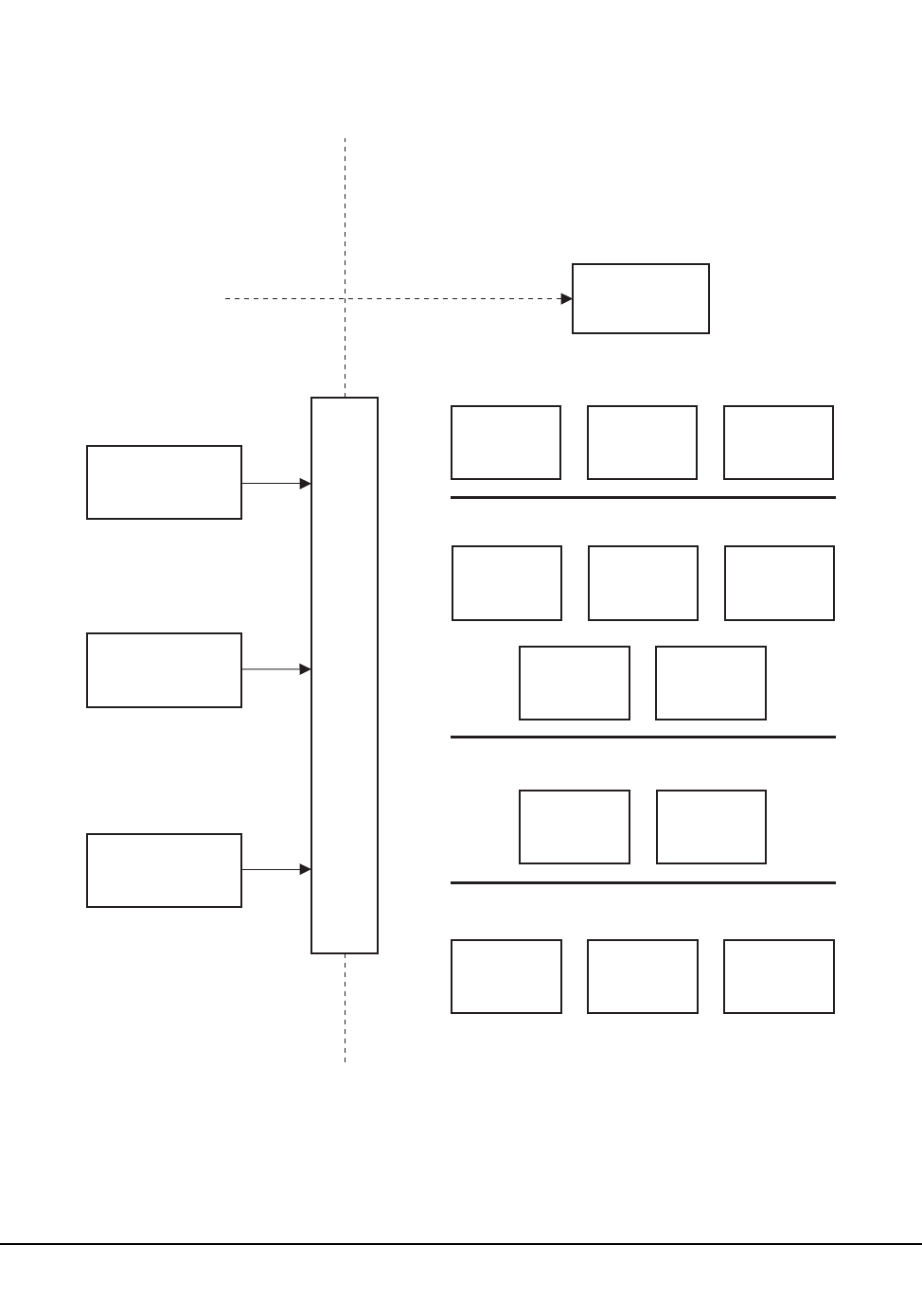
Chapter 1. System Description 5
1st ed., 6/30/04 - 312579601
Tape Management Interface external component
The tape management interface component receives and directs requests for
configuration, status, mount, dismount, and other information, from users and
programs.
USER’S
ADDRESS
SPACE
HSC STARTUP
COMMAND
(S SLS)
HSC ADDRESS SPACE
APPLICATIONS
OPERATOR
COMMANDS UTILITIES TMI
COMMON
SUBSYSTEM
COMMANDS
BATCH
UTILITIES
TAPE
MANAGEMENT
INTERFACE
(TMI)
COMMON
MOUNT/
DISMOUNT
CAP
COMMON COMMON
RECOVERY
COMMON
SERVICES
CONTROL
VOLUME/
CELL
CONTROL
CONFIGU-
RATION
CONTROL
COMMON
WTO
PROCESSING
SERVERS
DATA
BASE
SERVER
LMU
SERVER
COMMUNI-
CATIONS
COMPONENT
C46096
INITIALIZATION
/TERMINATION
A
D
D
R
E
S
S
S
P
A
C
E
C
O
M
M
U
N
I
C
A
T
I
O
N
S
S
E
R
V
E
R
Figure 1. HSC Architecture

6 VM/HSC 6.0 System Programmer’s Guide
1st ed., 6/30/04 - 312579601
VM Environment
The VM version of the HSC product is the implementation of the ACS Host Software
Component (HSC) product on VM. The principal interfaces and components under VM
are:
• VM Operating System (CP and CMS)
• The System Control Program (SCP)
• The Host Software Component (HSC)
• The tape management system (TMS)
• Operators and utility users.
VM Operating System (CP and CMS)
VM HSC requires relatively few system services. The VM system services that are used
are:
• Spool files
• Inter-User Communications Vehicle (IUCV)
• IUCV-based services *MSG and *BLOCKIO
• Diagnose
•RSCS
• VMDUMP Storage Dumps
• Interactive Problem Control System (IPCS) for VM/SP, or Dump Viewing Facility
for VM/XA and VM/ESA
• CMS (at initialization only).
CMS
The first portion of the SCP initialization process is executed under CMS. During this time
various files are read and some control data set locations are noted for reference. After the
program modules have been loaded into storage and the major control blocks have been
created, CMS is replaced by the SCP.

Chapter 1. System Description 7
1st ed., 6/30/04 - 312579601
System Control Program (SCP)
The service virtual machine executes a proprietary System Control Program which
provides a small subset of MVS services that include the following major components:
• Storage management
• Device management
• File management
• Task management
• Job management
• Processor management
• Communication
• Inter-machine communication
• Task recovery/termination.
Storage Management
The storage managed by the SCP is a single ‘‘real’’ storage range; no virtual storage
management is performed. The maximum amount of storage that is available to a user is
16 megabytes, but in actual practice 8 megabytes may be sufficient. Any paging or page
faults are managed by VM and are transparent to the virtual machine. The SCP associates
storage keys with ‘‘JOBS’’. VM job steps are mapped to unique storage keys. Storage
Management is a matter of managing available storage and allocating and deallocating
storage through standard macro calls.
Device Management
This component has exclusive control over SCP driven I/O activity to virtual devices.
IUCV is the interface to the DASD data sets which are accessed through requests to the
CP BLOCKIO service (using device I/O mainly for the Reserve-Release mechanism).
Other devices include several spool files for console, diagnostic, and performance logs,
and DASD I/O for minimal use. Also included with this component is the function of
logging unsuccessful attempts to log errors to the Error Recording Data Set (ERDS).
File Management
The SCP supports several access methods:
• Sequential (BSAM/QSAM) for spooled unit record input/output and DASD
input/output
• Direct (BDAM) for data base manipulation.
BSAM/QSAM is supported through EXCP processing of channel control word (CCW)
chains. BDAM files are accessed through IUCV communication to CP DASD BLOCKIO.
The requests are converted from a relative block to a physical block on DASD which is
passed to BLOCKIO.
No DASD file allocation is performed. All DASD data sets must be preallocated
OS-format data sets or CMS ‘‘reserved’’ minidisks.

8 VM/HSC 6.0 System Programmer’s Guide
1st ed., 6/30/04 - 312579601
Task Management
Multi-tasking is provided by the SCP to support the MVS-type task requests such as
POST, WAIT, ATTACH, etc. that the HSC expects. All modules are made resident at the
time of initialization. Also included in this component is the processing of System
Management Facility (SMF) records for output to a spool file.
Job Management
Most utilities are executed within the SCP environment as batch jobs punched by other
virtual machines. Special job statements define both the resources to be used and the
parameters to be passed to the desired program.
Processor Management
This component handles the resources of the virtual processor, including:
• interrupt handlers
• timer management
• IUCV paths and messages
• event tracing.
This component also handles authorization checking and PSW mode changing. Interrupts
consist of common processing, a first level handler which usually sorts out the interrupt
subtypes, and a second level handler which does the bulk of the processing. Timer services
include the TOD clock, the TOD clock comparator, and the CPU timer. Tracing includes
an internal table and a task which writes records to a spool file.
Communication
Standard MVS-type WTO/R and related operator communications are also supported,
with limitations on the routing and descriptor codes. The QEDIT interface, ECBs, and
various queues provide for inter-task communication.
Inter-Machine Communication
The Inter-User Communication Vehicle (IUCV) is a closed-loop technique used in VM to
communicate between users. A user sends an IUCV message and waits for a reply. This
service is used to transfer data between the HSC and the TMS.
Additionally, IUCV is used to access the BLOCKIO and MESSAGE system services. The
message service (*MSG) is used to intercept SMSG communications from operators.CP
DASD BLOCKIO forms the foundation of the SCP BDAM access method. BLOCKIO
reads and writes data to any DASD device with device independence, but the SCP must be
aware of the device type, especially when the data set is shared with an MVS host.

Chapter 1. System Description 9
1st ed., 6/30/04 - 312579601
Task Recovery/Termination
Task recovery is concerned with resource recovery, possible retry operations, and the
logging of software-detected errors. Terminations can be considered a special case of
recovery where resources must still be recovered but no retry or logging is necessary. The
SCP supports the most common ESTAE and ESTAI options and major SDWA fields.
Recovery includes a disabled and enabled (scheduled task) mode. The resources being
recovered are files to be closed, storage to be released, tasks to be terminated, and
messages and scheduled interrupts to be cancelled.
Host Software Component (HSC)
The HSC runs as an application program in the SCP environment. The HSC source code is
compiled by StorageTek.
The HSC accepts requests from the tape management interface (TMI) (see “Tape
Management System (TMS)” below) and drives the library hardware.
Tape Management System (TMS)
The TMS uses the IUCV interface to communicate with the virtual machine. It provides a
front end between the HSC and the user, and provides allocation, mount, and scratch pool
services. The HSC provides the TMS with mount/dismount service and assists it in
allocation for those volumes and drives which are under library control.
Note: In this document ‘‘TMS’’ is used to refer to any tape management system and not
any particular product.
Operators and Utility Users
Operators use CP SMSG to communicate with the SCP via the CP Message System
Service (*MSG). Utility users communicate with the SCP via punch spool files containing
special control statements. The authorization services allows only specified users to access
either of these interfaces; unauthorized users are disconnected from the service machine
when any attempt is made to communicate with the subsystem.
Virtual Machine Configuration
Within a VM host system the following virtual machines (users) exist:
• operator(s)
• ACS service machine (SCP and HSC)
• TMS service machine
• administrator(s)
• TMS requestors.
Various illustrations are provided to show relationships. Figure 2 on page 11 illustrates the
relationship of users to each other and the virtual machine and hardware relationships.
Figure 3 on page 12 illustrates how the library data sets may be shared by multiple,
dissimilar host systems.

10 VM/HSC 6.0 System Programmer’s Guide
1st ed., 6/30/04 - 312579601
HSC and Automated Cartridge System Interaction
After the HSC is started and the tape management system (TMS) service machine has
begun a dialog, mount or dismount requests are processed from the TMS, and the library
control data set is used to determine the location of the requested cartridge
(library-controlled or nonlibrary).
The library control data set is created on a DASD volume when you perform a data set
initialization during installation. Figure 4 on page 14 shows that it is necessary to share the
control data set between all hosts requiring access to the library.
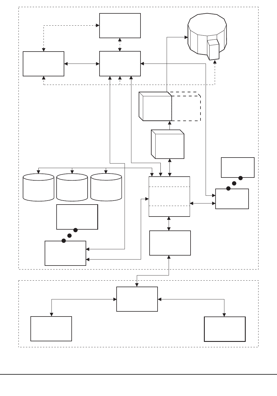
Chapter 1. System Description 11
1st ed., 6/30/04 - 312579601
PRIMARY
CONTROL
DATA SET
SECONDARY
CONTROL
DATA SET
STANDBY
CONTROL
DATA SET
LSM
CD
TMS
SERVICE
MACHINE
TMS
REQUESTOR
(CMS)
NONLIBRARY
TAPE
DRIVE
C27925
LMU
VM HOST A
LMU
3174/3274
TERMINAL
CONTROL
UNIT
OPERATOR
OPERATOR
VM HOST B
HSC
SCP
ACS
SERVICE
MACHINE
ADMINISTRATOR
ADMINISTRATOR
OPERATOR
(CMS)
ADMINISTRATOR
(CMS)
RSCS
RSCS
Figure 2. Virtual Machine Relationships
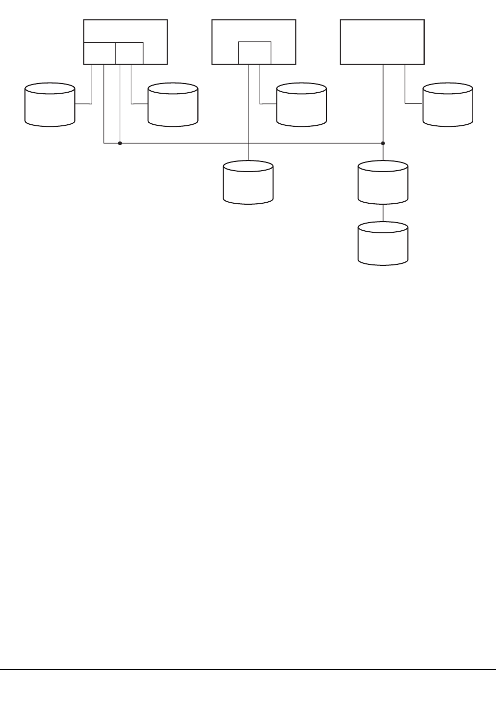
12 VM/HSC 6.0 System Programmer’s Guide
1st ed., 6/30/04 - 312579601
Automated cartridge mounts/dismounts are performed in response to calls to the tape
management interface. The HSC determines that a mount/dismount is required for a
volume under automated library control (cartridge resides in an LSM storage cell), and it
communicates with the appropriate LMU.
If the request is for a mount, the following information is communicated to the LMU:
• the LSM and panel/row/column in which the volume resides
• the destination LSM (where the volume is to be mounted on a transport).
If all drives in an LSM are busy, a cartridge can be moved to another LSM to satisfy the
mount request. This action is performed without operator intervention, since the pass-thru
port (PTP) makes the cartridge available to the attached LSM.
If the request is for a dismount, this information is passed to the LMU:
• the LSM, cartridge drive, and transport in which the volume resides
• the destination (storage cell, CAP, or PTP) of the cartridge.
JOURNALJOURNAL
C29335
JOURNAL
VM/XA HOST VM/SP HOST
ACS
SERVICE
MACHINE
ACS
SERVICE
MACHINE
MVS/XA
GUEST
MVS HOST
MVS/XA
(JES2 OR JES3)
JOURNAL
PRIMARY
CONTROL
DATASET
SECONDARY
CONTROL
DATASET
STANDBY
CONTROL
DATASET
Figure 3. Shared Library Data Sets

Chapter 1. System Description 13
1st ed., 6/30/04 - 312579601
Automated Mount
Figure 4 on page 14 shows the LMU communicating with the LSM through LAN 0. In this
illustration, LAN 1 is represented as the backup used in case of a LAN 0 failure.
Note: The HSC can select either LAN for communications with the LSM(s). Whichever
LAN is not picked becomes the backup.
Within the LSM, the robot’s hands are positioned to the correct panel/row/column
cartridge location. The external Tri-Optic label is verified by the robot’s vision system, the
robot’s hand extends, and the hand grasps the cartridge from its storage cell. The robot’s
hand retracts with the cartridge and the robot moves to the appropriate position.
(PTP cell or transport). The robot hand extends and the cartridge is positioned and released
at its destination (PTP cell or transport).
If the destination is a PTP cell, the cartridge is made available to the adjacent LSM, and
the process repeats until the cartridge is placed in a transport.
Automated Dismount
An automated dismount is the reverse of the mount procedure. The LMU communicates
with the LSM via the LAN, and the robot’s hands are positioned at the transport to be
dismounted. The external Tri-Optic label is verified using the vision system. A hand is
extended and the cartridge is grasped from the transport. The hand retracts with the
cartridge and the robot is moved to the cartridge’s destination. The hand is extended and
the cartridge is positioned and released into the storage cell.
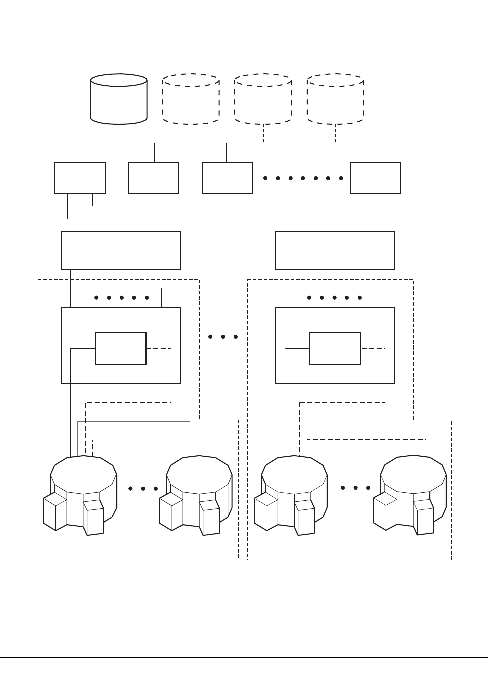
14 VM/HSC 6.0 System Programmer’s Guide
1st ed., 6/30/04 - 312579601
PRIMARY
CONTROL
DATA SET
SECONDARY
CONTROL
DATA SET
STANDBY
CONTROL
DATA SET JOURNALS
HOST 1 HOST 2 HOST 3 HOST 16
3274
CONTROL UNIT (0) 3274
CONTROL (7)
LOCAL
AREA
NETWORK
LOCAL
AREA
NETWORK
(STATIONS 1 - 16) (STATIONS 1 - 16)
LMU 0
LAN 0 LAN 0LAN 1 LAN 1
LMU 255
LSM 0 LSM 0LSM 15 LSM 15
ACS 0 ACS 255
CD CD
CD CD
C27409
Figure 4. HSC/Automated Cartridge System Interaction

Chapter 1. System Description 15
1st ed., 6/30/04 - 312579601
In a library configuration containing more than one LSM, if a cartridge exchange
operation occurs to obtain the cartridge for mounting, the cartridge may be returned by
one of these possible ways:
• If the MNTD Float command is set to ON (the HSC initial value), the cartridge is
returned to any new cell location in the LSM containing the tape transport from
which it was dismounted. For more information about the MNTD Float command,
refer to Chapter 2, ‘‘Commands, Control Statements, and Utilities’’ in the HSC
Operator’s Guide.
• If the MNTD Float command is set to OFF, the cartridge is passed through to the
origin LSM and placed into its originating cell location. For more information about
the MNTD Float command, refer to Chapter 2, ‘‘Commands, Control Statements,
and Utilities’’ in the HSC Operator’s Guide.
• If the LSM is full, the cartridge is passed thru to another LSM and placed in any cell
location.
• A temporary enter on a mount operation means an eject upon dismount (the cartridge
does not remain in the LSM).
The library control data set is automatically updated to reflect the new location of the
cartridge.
Dual LMU Environment
In a dual LMU environment, the HSC maintains contact with both LMUs. Both LMUs are
varied online. One LMU functions as the master LMU and the other functions as the
standby LMU. Requests and responses are channeled through station paths on the master
LMU. Paths on the standby LMU are online, but not used.
The master LMU continually informs the HSC of the status of the standby LMU. The
HSC informs the operator when status changes.
The standby LMU constantly polls the master LMU. If the master LMU fails, the standby
LMU informs the HSC that status has changed. The standby becomes the master. The
HSC also informs the operator that the previous master LMU is not communicating.
At switchover, the HSC:
• notifies the operator that switchover is occurring
• verifies the configuration for the LMU
• sends the new master LMU all the work that was in progress
• terminates ENTER operations.
After switchover, the HSC sends the new master all ACS requests.
Switchover should not affect movement in process. All moves should complete. If not, the
cartridges become errant and are found when the LSMs perform ‘‘quick initialization’’
processing. ENTER operations must be restarted after switchover.

16 VM/HSC 6.0 System Programmer’s Guide
1st ed., 6/30/04 - 312579601
User Control of HSC Functions
Various controls are in place in the HSC software to permit you to select how the HSC
functions. Macros, Utilities, and PARMLIB control statements are normally used by the
systems programmer to tune and customize the system. Commands are normally invoked
by a systems operator in the performance of daily operations tasks. A description of the
function of each of these available controls follows.
Macros
Macros are provided primarily to help you set up the library software configuration
or library generation (LIBGEN).Refer to Chapter 6, ‘‘Creating the Library
Configuration File (LIBGEN)’’ in the HSC Installation Guide for detailed
information about the LIBGEN macros and how they are used to configure a library.
Utilities
Utilities are provided to allow you to manage library resources. The utilities enable
you to dynamically:
• perform maintenance on control data sets
• control cartridge and scratch volume functions
• produce performance, activity, and inventory reports relating to a library.
Refer to Chapter 4, “Utility Functions” on page 169 for detailed information about
the HSC utilities and how they are used to manage library resources.
PARMLIB Control Statements
PARMLIB control statements are provided to enable you to set initial values for
system functions at HSC initialization. The PARMLIB control statements define
HSC functions such as:
• host-to-host communications parameters
• definition of scratch subpools
Note: Refer to “Options Offered by PARMLIB Control Statements” on page 84
for an important warning about defining scratch subpools.
• data set definitions including: the primary, secondary, standby control data sets,
and journals
• extended parameter list for startup.
Refer to “PARMLIB Control Statements” on page 83 for detailed information about
the control statements and usage.

Chapter 1. System Description 17
1st ed., 6/30/04 - 312579601
Commands
Operator commands are available for Systems Operators to use in daily library
operation to perform various tasks. Commands perform such functions as:
• assigning a preference to a specific cartridge access port (CAP)
• displaying system status, such as control data set status, ACS, LSM, and
volume status
• entering, ejecting, mounting, and dismounting cartridges
• setting of system parameters.
Refer to the HSC Operator’s Guide for information about HSC operator commands
and usage.

18 VM/HSC 6.0 System Programmer’s Guide
1st ed., 6/30/04 - 312579601

Chapter 2. Host Software Component Functions 19
1st ed., 6/30/04 - 312579601
Chapter 2. Host Software Component Functions
Overview of HSC Functions
This chapter describes the basic function of the HSC. Functions for each of the HSC
components fit within the architecture structure presented in Figure 1 on page 4. Not all of
the components of the architecture structure have functions directly visible to you. Only
those HSC functions that you can control or those that are operationally apparent are
described in this chapter.
System functions relating to HSC architecture components represented in Figure 1 on
page 5 include:
• installation
• initialization/termination
• mount/dismount processing
• volume/cell control
• CAP processing
• common recovery
• command
• utility
• LMU server
• communications
• tape management interface (TMI)
• batch application program interface.
The Automated Cartridge System provides the facilities and software to perform various
functions with or without operator intervention. Such major system functions are
described in this chapter.
Automatic Functions of the HSC
Among the functions handled automatically by the HSC are:
• mounting and dismounting of cartridges
• automatic and manual operating modes
• handling of abnormal situations occurring during mounting or dismounting of
cartridges
• Cartridge Access Port processing to allow the operator to enter or remove cartridges
• tape management system assistance

20 VM/HSC 6.0 System Programmer’s Guide
1st ed., 6/30/04 - 312579601
• automatic cleaning of tape transports with cleaning cartridges under the control of
the HSC and the library
• restricting the write access to volumes in the library through the Virtual Thumbwheel
feature
• dual LMU support
• control data set recovery.
Facilities Available for User Control of HSC Functions
There are facilities available for system programmers and operators to use to control
various system functions. These include:
•macros
• utilities
• PARMLIB control statements
• operator commands.
Installation Functions
Installation functions pertain to installation or reconfiguration processing for the HSC
subsystem. Since these topics are extensive, they are presented in a separate document.
The HSC Installation Guide presents detailed information about installation planning and
instructions, including:
• Planning the configuration
• Performing preinstallation procedures
• Installing HSC software
• Defining the library configuration (LIBGEN)
• Defining PARMLIB control statements
• Initializing the control data sets
• Verifying library generation
• Starting HSC execution
• Testing the installation
• Planning and executing cartridge migration into the library
• Migration planning
• Performing library modifications.

Chapter 2. Host Software Component Functions 21
1st ed., 6/30/04 - 312579601
Initialization/Termination Functions
Initialization/termination functions control initialization and termination of HSC
components. This section describes the major initialization/termination functions.
HSC Service Levels
To provide you with a more flexible, dynamic, automated cartridge mounting execution
environment, the HSC has a service level strategy. Operation at either of the two service
levels impacts the HSC subsystem. Operation flexibility is provided at a base service level
to tolerate failures in certain isolated areas without impacting the functions of other
sections of the HSC or your entire data center. Overall, this fault-tolerant HSC gives you
greater availability of your automated library and lessens the need to shutdown and
reinitialize. The HSC subsystem operates at two service levels:
Base service level
provides minimal functionality keeping the HSC running while having the capability
of applying software maintenance or altering the subsystem parameters at the same
time. This level is the lower level of functionality.
Full service level
provides full functionality of the HSC.
Normally the HSC initializes to the full service level when started. HSC can be started at
the base service level by specifying the BASE parameter in the startup SLKJCL file. Refer
to “Initializing the HSC to the Base Service Level” on page 129 for more information
about HSC startup.
Description of Base Service Level
The base service level is the nucleus of the HSC subsystem. It involves the functions
necessary to execute as an extension of the operating system. The service level and its
functions satisfy the requirements defined by the operating environment in place at the
time of execution. Base service level functions include the capabilities to:
• issue subsystem commands
• execute certain utilities
• access the control data sets
• support the operating system interfaces and front-ends and maintain HSC
host-to-host communications.
All operator commands can be issued with the HSC executing at the base service level.
However, the commands which involve library hardware cannot perform their function
completely. Table 1 on page 21 indicates which commands have complete functionality at
the base service level.
Table 2 on page 22 indicates which utilities can be executed at the base service level.

22 VM/HSC 6.0 System Programmer’s Guide
1st ed., 6/30/04 - 312579601
Description of Full Service Level
The full service level of operation for the HSC provides all of the functions available and
necessary to invoke and sustain complete library operations. These functions include:
• mount/dismount processing
• CAP processing
• cartridge and cell inventory management
• LMU access
• library resource recovery
• support for utilities which require services from the hardware
• support for the tape management interface.
At initialization, the HSC builds data areas, loads program modules, and sets up the
required operating system services to support the two service levels of operation.
Termination of the HSC, including normal termination and abnormal termination through
abends removes the service level structure and services.
For example, on your system with the HSC operating at full service level, all commands,
utilities, etc. are fully functional. Should you decide to manually intervene by issuing the
Service Level command (SRVlev) to change from full to base service level, the
functionality of the HSC is reduced. Refer to ‘‘Adding SMF Parameters’’ in the HSC
Installation Guide.
Conversely, you can change the base service level operation to full service level.

Chapter 2. Host Software Component Functions 23
1st ed., 6/30/04 - 312579601
Table 1. HSC Command Execution at Base and Full Service Levels
Command
Service Level Execution
Base Full
CAPPref NO YES
CDs YES YES
CLean NO YES
COMMPath YES YES
DISMount NO YES
Display YES*YES
DRAin NO YES
EJect NO YES
ENter NO YES
Journal YES YES
LIst YES YES
MNTD NO YES
MODify (F) NO YES
MONITOR (MN) YES YES
Mount NO YES
MOVe NO YES
OPTion YES YES
RECover NO YES
RELease NO YES
SENter NO YES
SRVlev YES YES
STOPMN (PM) YES YES
SWitch NO YES
TRace YES YES
TRACELKP YES YES
Vary NO YES
VIew NO YES
Warn NO YES
* Display options that require hardware interaction are not valid at the base
service level.

24 VM/HSC 6.0 System Programmer’s Guide
1st ed., 6/30/04 - 312579601
Table 2. Utility Execution at Base and Full Service Levels
Utility
Service Level Execution
Base Full
AUDIt NO YES
BACKup YES YES
EJECt NO YES
ENTEr NO YES
LIBGen YES YES
MOVe NO YES
OFFLoad YES YES
REPLaceall YES YES
RESTore NO NO
SCRAtch YES YES
SCREdist NO YES
SET YES YES
UNSCratch YES YES
UNSElect YES YES
VOLRpt YES YES

Chapter 2. Host Software Component Functions 25
1st ed., 6/30/04 - 312579601
Displaying/Setting Service Level
An HSC operator command, SRVlev, sets a different service level. Refer to information
presented on the Display command in Chapter 2, ‘‘Commands, Control Statements, and
Utilities’’ in the HSC Operator’s Guide for information on how to display the current HSC
service level.
Starting the HSC Subsystem at Base Service Level
If the HSC and the library are new to your data center, you may want to install the HSC
software and start the subsystem at the base service level before your library hardware is
physically installed. Starting the HSC at the base service level allows you to perform
many of the preliminary tasks involved in configuring your library and performing
preliminary tests on basic operation.
Normally the HSC subsystem is initialized to the full service level when started. The HSC
can be started at the base service level only by specifying the BASE parameter in the
startup SLKJCL file. Then, the Service Level (SRVlev) command can be used to bring the
HSC to full service level whenever you are ready.
Refer to “Initializing the HSC to the Base Service Level” on page 129 for information
about setting the service level at HSC initialization.

26 VM/HSC 6.0 System Programmer’s Guide
1st ed., 6/30/04 - 312579601
Media Type and Recording Technique Processing
When a job requests specific media type and recording technique, the HSC uses
information provided by TAPEREQ control statements to select a cartridge with the
appropriate media type and influence the tape management system to allocate a transport
with the requested recording technique.
Chapter 2. Host Software Component Functions 27
1st ed., 6/30/04 - 312579601
MEDia and RECtech Parameters
When a TMI request or MOUNT command is executed, the HSC searches the appropriate
control statements to determine the media type and recording technique to assign to the
data set.
The MEDia and RECtech parameters are specified on the TAPEREQ and VOLATTR
control statements. Parameter values associated with MEDia and RECtech, and their
hierarchy, are shown in the following figure:
MEDIA TYPES RECORDING TECHNIQUES
STK2
STK2P
STK2W
DD3A
DD3B
DD3C
DD3D
STANDARD
ECART
ZCART
LONGITUD
STK1
STK1R
STK1U
DD3
36ATRACK
36BTRACK
36CTRACK
STK2PB35
STK2PB34
STK2PA34
STK2PA35
HELICAL
STK2P
STK2P35
STK2P34
STK2PA
STK2PB
STK1R
STK1RB34
STK1RB35
STK1RB
STK1RA35
STK1RA34
STK1RA
STK1R35
STK1R34
STK1RAB
STK1RAB4
STK1RAB5
STK1RC
STK1RC34
STK1RC35
LONGITUD
18TRACK
36TRACK
HELICAL DD3

28 VM/HSC 6.0 System Programmer’s Guide
1st ed., 6/30/04 - 312579601
Model Parameter
The MODel parameter is specified on the TAPEREQ and UNITATTR statements. MODel
values are processed as if they were RECtech values. UNITATTR control statements do
not use the RECtech parameter. Table 3 shows the relationship between MODel and
RECtech parameters.
Table 3. MODel/RECtech Translation
MODel Resulting RECtech
4480 18track
4490 36Atrack
9490 36Btrack
9490EE 36Ctrack
SD3 DD3
9840 STK1R34
984035 STK1R35
T9840B STK1RB34
T9840B35 STK1RB35
T9840C STK1RC34
T9840C35 STK1RC35
T9940A STK2PA34
T9940A35 STK2PA35
T9940B STK2PB34
T9940B35 STK2PB35

Chapter 2. Host Software Component Functions 29
1st ed., 6/30/04 - 312579601
Matching VOLATTR and TAPEREQ Statements
The type of request (specific or nonspecific) determines whether the HSC uses media type
and recording technique information from the VOLATTR statement or the TAPEREQ
statement. (See “Precedence of VOLATTR and TAPEREQ Statements” for additional
information.)
The statements are searched until matches are found for both the media type and recording
technique. The first control statement that matches the selection (input) criteria is used;
there is no attempt to determine the ‘‘best’’ match.
Since MEDia and RECtech parameters may or may not be specified on a single
TAPEREQ or VOLATTR control statement, one of the following conditions results:
• Both media type and recording technique are provided by one control statement.
• Media type is provided by one TAPEREQ statement and recording technique is
provided by another TAPEREQ statement.
• Media type is provided by one VOLATTR statement and recording technique is
provided by another VOLATTR statement.
• Media type is provided by a VOLATTR statement and recording technique is
provided by a TAPEREQ statement.
• Media type is provided by a TAPEREQ statement and recording technique is
provided by a VOLATTR statement.
As a result of determining the precedence of media and recording technique information
between the VOLATTR and TAPEREQ statements, ‘‘final’’ media type and recording
technique values are produced. The final media type and recording technique are
compared to the aggregate media type and recording technique of the EDL. If an
inconsistency is detected, a message is issued to this effect, and the media type and
recording technique of the EDL are used. If the final media and recording technique are
consistent with the EDL, they are used to satisfy the request, unless doing so would cause
the job to fail.
StorageTek recommends placing all control statements in a most specific to least specific
order. Very general VOLATTR or TAPEREQ statements should be placed last to act as a
global or site defaults.

30 VM/HSC 6.0 System Programmer’s Guide
1st ed., 6/30/04 - 312579601
Precedence of VOLATTR and TAPEREQ Statements
The precedence of VOLATTR and TAPEREQ statements depends on whether the request
is for a specific or nonspecific volume.
Specific Volume Requests
For a specific volume request, VOLATTR information overrides TAPEREQ information
provided that the VOLATTR statements supply both media type and recording technique.
For example, if the TAPEREQ statement specifies MEDia(ECART) RECtech(36track)
and the VOLATTR statement specifies MEDia(Standard) but does not specify RECtech,
the result is MEDia(Standard) from the VOLATTR statement and RECtech(36track) from
the TAPEREQ statement.
If the VOLATTR statement provides a value for RECtech, then that recording technique is
used, but the TAPEREQ statement can ‘‘refine’’ the RECtech value. For example, the
VOLATTR statement specifies a recording technique of 36track, and the TAPEREQ
statement specifies 36Btrack, then 36Btrack is used.
Nonspecific Volume Requests
Note: When mixing media types, the user must define VOLATTR statements because
scratch counts are determined entirely from VOLATTR information.Accurately defined
VOLATTR statements are critical for correct processing of nonspecific volume requests.
The HSC analyzes the TAPEREQ information to determine the required media type and
recording technique, and then tries to locate available scratch volumes in the library that
match these values. If no matching scratch volumes are available, HSC rejects the request.
Scratch Selection
Scratch volumes are segregated by means of scratch subpooling with VOLATTR
statements. Assuming that requested subpool definitions do not conflict with the
applicable VOLATTR statements, the HSC provides the following services to satisfy a
request:
• If scratch volumes are segregated by defining subpools and specifying VOLATTR
statements, the HSC ensures that a volume with the appropriate media type is
selected from the correct subpool.
• If scratch volumes are segregated only by defining subpools, the HSC selects a
standard cartridge from the correct subpool. A standard cartridge is selected because
this is the default when VOLATTR statements are not defined.
• If volumes are segregated only by specifying VOLATTR statements, the HSC
ensures that a volume with the appropriate media type is selected.

Chapter 2. Host Software Component Functions 31
1st ed., 6/30/04 - 312579601
How To Resolve Scratch Shortages
Whenever the HSC cannot satisfy a library mount request for a scratch cartridge, the
following message is issued:
... SHORTAGE ACS AA; MMMMMMMM; RRRRRRRR; SSSSSSSS; ...
This indicates that one of the following has occurred:
• there are no scratch cartridges in the ACS
• there are no scratch cartridges in the requested subpool in the ACS
• there are no scratch cartridges of the requested media type or recording technique in
the ACS
• there are no scratch cartridges of the requested media type or recording technique in
the requested subpool in the ACS.
The message identifies the media type (MMMMMMMM), recording technique
(RRRRRRRR), and subpool (SSSSSSSS) of the scratch shortage.
Note: If the subpool name indicates “SUBPOOL 0”, this means one of the following:
• scratch subpooling is in effect and no subpool was specified
• scratch subpooling is not in effect.
If the recording technique specified in the request is 18-track, then the media type must be
standard capacity with a recording technique of 18track, LONGItud, or not specified.

32 VM/HSC 6.0 System Programmer’s Guide
1st ed., 6/30/04 - 312579601
If the recording technique specified in the request is 36-track, examine the TAPEREQ
statements to determine if the requested media must be:
• Standard and 36track
• Long and 36track
• Standard and LONGItud
• Standard and no recording technique specified.
Notes: If the default VOLATTR specifies MEDia(Standard) RECtech(18track), then
scratch volumes defined as MEDia(Standard) and no recording technique specified cannot
be mounted on a 36-track device.
If a scratch volume is requested from a specific subpool, then a scratch cartridge of the
requested media type must be entered into that subpool in the ACS.

Chapter 2. Host Software Component Functions 33
1st ed., 6/30/04 - 312579601
Mount/Dismount Functions
Mount and dismount functions consist of the following processing:
• mounting specific volumes
• mounting scratch volumes
• dismounting library volumes
• handling abnormal mounts and dismounts
• virtual thumbwheel (VTW)
• automated tape transport cleaning.
The mount/dismount component receives the request sent by the tape management
interface component and makes the mount/dismount of cartridges occur.
Each mount/dismount function is described in this section.
Several options exist to allow users to specify how they want mount/dismount to react in
various situations. Refer to the ‘‘MNTD (Mount/Dismount Options) Command and
Control Statement’’ in the HSC Operator’s Guide for a description of these options.
Mount Processing for Specific Volumes
The HSC determines when a library volume is to be mounted on a library-controlled
transport. It maintains a record of the library location for each cartridge and instructs the
LMU to mount the requested cartridge on the selected transport.
Mount processing occurs as a result of:
• the tape management system (TMS) interpreting a request for library transports
• issuance of the HSC operator Mount command
• change of the HSC from base service level to full service level
• startup of an HSC subsystem
• a clean request.
A volume may be temporarily or permanently entered into the library to satisfy a mount on
a library transport. If a volume is temporarily entered into an LSM, a notation is made in
the library control data set for this volume to be automatically ejected, via a CAP, when
the volume is dismounted.

34 VM/HSC 6.0 System Programmer’s Guide
1st ed., 6/30/04 - 312579601
Mount Processing for Scratch Volumes
To process scratch mount requests, the HSC determines which volumes within an LSM
are considered as scratch volumes. The HSC makes the determination from information
contained in the library control data set.
Note: A scratch tape is marked as nonscratch when it is mounted even if it is not written
on.
Normally, only requests for nonspecific VOLSERs and the appropriate label type (as
defined in the LIBGEN) are considered as requests for scratch volumes. However, the
HSC allows selection of scratch volumes from different scratch subpools and different
label types via interaction with the TMI.
In addition, other means are available for controlling scratch volume activity. These are at
the operator command and programmer utility levels. Refer to “Scratch Subpool
Management” on page 39 for more information.
To minimize pass-thru movement of the scratch cartridges, the HSC always orders drives
for selection in ascending order by scratch count.
The scratch status of cartridges listed in the library control data set is updated through the
use of the Scratch Update utility. The Scratch Update function accepts a list of volume
serial numbers for addition to, or deletion from the control data set’s list of scratch
volumes. If desired, the entire scratch list may be deleted by using the Scratch Update
utility.
Dismount Processing for Library Volumes
The HSC determines when a library volume is to be dismounted from a library transport.
Dismount processing occurs as a result of:
• a tape management interface request identifying library transports, or
• issuance of the HSC operator DISMount command
• the completion of a clean operation.
The MNTD Float command is useful for influencing cartridge exchange operations and
returning cartridges to their original cells or to new cells after a mount/dismount request
has been completed.
If the MNTD command Float option is on (i.e., MNTD Float(ON)), when a volume is
passed to a transport in another LSM, dismount processing frees the original cell location
and assigns the volume to a cell in the same LSM as the transport as long as empty cells
exist. If no empty cells exist, a location is chosen in the nearest LSM with free cells or
volumes can be forced to their original home cell at dismount time.
If Float is off, the HSC returns the volume to its original home cell location.
The MNTD SCRDISM parameter allows scratch volumes mounted in a WolfCreek LSM
to be archived either in the same WolfCreek LSM or in the next largest storage device (the
9310 LSM).

Chapter 2. Host Software Component Functions 35
1st ed., 6/30/04 - 312579601
The MNTD PASSTHRU parameter works with SCRDISM by setting the maximum
number of pass-thrus that can occur for a cartridge that is to be archived.
Refer to the ‘‘MNTD (Mount/Dismount Options) Command and Control Statement’’ in
the HSC Operator’s Guide for a description of all the options associated with this
command.
If the dismount occurs for a temporary volume, the volume is ejected through a CAP, and
a message informs the operator to retrieve the cartridge.
You can intervene in how the HSC controls library operation. Tape cartridge movement, as
well as many other functions, can be controlled to function in ways that you prefer. Refer
to Chapter 4, “Utility Functions” on page 131 for information about utilities that can be
used to control HSC operation of the library. Refer to the HSC Operator’s Guide for
information about operator commands that can be used for controlling library operation.
Abnormal Mounts/Dismounts
The HSC handles abnormal situations through communication with the operator so
intervention may take place to accomplish the mount. The following examples indicate the
types of situations in which this communication takes place:
• The transport is in an ACS, but the volume is not. The HSC issues a WTOR.
The operator may:
- reply that the mount request is to be ignored and the TMS request is canceled
- reply that the volume is to be permanently entered into the library
- reply that the volume is to be temporarily entered into the library
- enter the volume and the HSC automatically retries the volume lookup.
• The volume and/or transport resides in a manual mode LSM.
- All mount and dismount requests are queued until either a response is made to
one of the manual mode WTORs or the LSM is returned to automatic mode. At
this point, all queued requests are processed.
- A console interaction (WTOR) is provided to indicate the VOLSER’s location.
- When a transport’s LSM is in manual mode or the robotic control path to the
LSM is inoperative, operator intervention is requested to assist in performing
the mount.
- When the transport being dismounted is in a manual mode LSM, the operator is
requested to dismount the cartridge and to remove it from the LSM. The volume
is deleted, or the operator may be asked if the volume is to be deleted, from the
control data set.
The volume may be deleted from the control data set depending on the setting
of the MNTD command. A delete occurs unconditionally if MNTD
Dismount(Auto) is entered. Otherwise, a reply is required.
36 VM/HSC 6.0 System Programmer’s Guide
1st ed., 6/30/04 - 312579601
• The TMS is unsatisfied with the scratch cartridge provided.
- The HSC dismounts the current volume, removes it from the scratch list, and
mounts another scratch volume.
Virtual Thumbwheel (VTW)
Virtual thumbwheel is the HSC function that allows read-only access to a cartridge in an
ACS. Normally cartridges are stored in the library with the physical cartridge thumbwheel
enabled for writing. There are circumstances where it is desirable to allow enforced
read-only access to a volume without removing the volume from the LSM, changing the
physical thumbwheel, and reentering it.
The HSC may, via the VM HSC Tape Management Interface (TMI) or by operator
command, cause a volume to be mounted while instructing the transport to allow
read-only access to the volume by simulating that the thumbwheel is in a read-only state.
In this virtual thumbwheel mode, the transport ignores the fact that the volume might be
physically enabled for writing.
The transport never writes on a cartridge that is physically write-protected.
Tape Management Interface
The TMI utilizes virtual thumbwheel when the PROTECT parameter is specified with
MOUNT requests. Refer to the HSC Interface to Tape Management Systems Manual for
interface details.
HSC Mount Command Support
The Mount command provides support for virtual thumbwheel. The Readonly operand for
the Mount command enables a volume to be mounted with the virtual thumbwheel set to
write protect.
Example of Mount Command with Readonly Operand
Note: Operands for operator commands are positional. In the example above, two
commas must follow the drive operand to indicate that the host-id operand is not specified.
Refer to the HSC Operator’s Guide for details on the HSC Mount command.
MOUNT VOL001,B00,,READONLY
Chapter 2. Host Software Component Functions 37
1st ed., 6/30/04 - 312579601
Tape Transport Cleaning
The HSC allows you to automate the cleaning process or to manually clean
library-attached tape transports. When a library transport needs to be cleaned, it informs
the LMU, which broadcasts a ‘‘drive needs cleaning’’ message to all connected hosts.
The LMU broadcast causes the HSC to issue a console message indicating that a transport
needs cleaning. Until a cleaning cartridge is loaded, future mounts continue to initiate this
message. If auto-cleaning is disabled, HSC processing is complete, and the transport must
be cleaned manually. To manually clean a transport, see “Manual Tape Transport
Cleaning” on page 37 for more information.
Note: The initial value for transport cleaning is for automated cleaning to be disabled.
Automated Tape Transport Cleaning
If auto-cleaning is enabled, the HSC sets the transport to ‘‘needs cleaning’’ status. The
next time a mount is issued for that tape transport, the following cleaning process is
invoked prior to mounting the requested cartridge:
1. The HSC selects a cleaning cartridge from the pool of cleaning cartridges in the LSM
that contains the tape transport that needs cleaning (or from the closest LSM that
contains a compatible cleaning cartridge).
2. The cleaning cartridge is mounted.
3. The tape transport is cleaned.
4. The cleaning cartridge is dismounted.
When the cleaning process is complete, the original requested cartridge is mounted on the
transport.
Notes: If auto-cleaning is enabled, cleaning can also be scheduled for a transport by
issuing the CLean command. See “Activating Automated Cleaning” for additional
information.
Activating Automated Cleaning
The MNTD AUtocln command is used to turn auto-cleaning on or off on a host-by-host
basis.
The following example shows how to activate automatic cleaning.
Notes: It is probably more useful to have automated cleaning on for all hosts in a JES2
installation unless library transports are allocatable only by some hosts. In a JES3
environment, most mounts are done by the global processor and auto-cleaning should be
set on for at least the global processor.
MNTD AUTOCLN(ON)
38 VM/HSC 6.0 System Programmer’s Guide
1st ed., 6/30/04 - 312579601
Once auto-cleaning is activated, the CLean command can be issued to initiate cleaning of
specified drives on specified hosts.
An example of issuing the CLean command is:
Notes:
1. The MNTD AUtocln command must be set to ON before attempting to use the
CLean command.
2. The CLean command sets the transport to ‘‘needs cleaning’’ status. The cleaning
process is not initiated until the next mount is issued against the transport. Refer to
the HSC Operator’s Guide for an explanation of the CLean command.
Identifying Cleaning Cartridges
Cleaning cartridges are identified to the HSC by a unique three-character alphabetic
prefix in their volser. All cartridges identified with that prefix make up a pool of
cleaning cartridges in each LSM.
The parameter CLNPRFX, contained in the LIBGEN SLILIBRY macro, specifies
the volser prefix for cleaning cartridges. CLNPRFX must be three alphabetic
characters, and identifies cleaning cartridges associated with the library. The default
is CLN. Refer to ‘‘SLILIBRY Macro’’ in the HSC Installation Guide for additional
information.
Notes:
1. Any cartridges identified by the cleaning prefix are treated exclusively as
cleaning cartridges; they cannot be scratched or initialized by HSC utilities.
2. Extra overhead can be avoided if the range of cleaning cartridge volsers in an
LSM and ACS is both narrow and dense. For example, if three cleaning
cartridges are in a single LSM, labels of CLN020, CLN021 and CLN022 would
cause less processing overhead than if they were labeled CLN001, CLN501 and
CLN901.
3. The cleaning prefix can be changed using the SET CLNPRFX utility. However,
before the cleaning prefix is changed, all cleaning cartridges must be ejected
from all ACSs. See the description of the SET utility for the complete
procedure. Cleaning Media and Drive Compatibility Tape transports must be
cleaned with cleaning cartridges of a compatible cleaning media type.
Longitudinal transports must be cleaned with longitudinal cleaning media,
RedWood transports must be cleaned with helical cleaning media (DD3D), and
9840 transports must be cleaned with 9840 cleaning media (STK1U).
4. Different cleaning cartridge media types may have different maximum cleaning
usage limits. Grouping cleaning cartridges of different media types into
different volser ranges makes it easier to specify these limits with the
CLEAN 582 HSTA

Chapter 2. Host Software Component Functions 39
1st ed., 6/30/04 - 312579601
VOLATTR control statement MAXclean parameter(s). For example, if the
helical cleaning cartridges have volsers between CLN500 and CLN599, the
following VOLATTR statement can be used to set a different maximum
cleaning usage limit for this range of helical cleaning cartridges: VOLATTR
SERial(CLN500-CLN599) MAXclean(nn)
5. Contact your StorageTek Customer Services Engineer for appropriate
MAXclean values for different cleaning media types. Limits on the Use of
Cleaning Cartridges Cleaning cartridges should only be used a limited number
of times. The MNTD MAXclean command globally specifies how many
cleaning operations are allowed before a cleaning cartridge should be removed
from the ACS and replaced (the default is 100 uses). This maximum cleaning
usage limit can be different for different cleaning media. Use the VOLATTR
MAXclean parameter to specify a different maximum cleaning limit for
different cleaning cartridge media.
6. Refer to ‘‘MNTD (Mount/Dismount Options) Command and Control
Statement’’ in the HSC Operator’s Guide and to “Volume Attribute
(VOLATTR) Control Statement” on page 110 for additional information about
the MAXclean value.
7. Ejecting and reentering used cleaning cartridges should be avoided. When a
cartridge is ejected and reentered, its select count is set to zero. The select count
is used to track the number of times a cleaning cartridge has been used. Used
cleaning cartridges which are reentered will be used more times than specified
by the applicable MAXclean value. Each cleaning media type is used in a
different way to clean tape transports. Some media types use the same cleaning
surface many times, while other media types use the cleaning surface only once.
Some media types use the cleaning surface only a few times before they are
unable to clean a tape transport.
When a cleaning cartridge is no longer able to adequately clean a tape transport, it is
over-use.
Over-use (Over-limit and Spent) Cleaning Cartridges
An over-use cleaning cartridge means either that the usage (select) count is over the
MAXclean value (‘‘over-limit’’) or all of its cleaning surface is used or ‘‘spent.’’
•An over-limit cleaning cartridge has been used more than the value (limit) specified
by either the MNTD MAXclean or VOLATTR MAXclean settings. This cleaning
cartridge may not be able to adequately clean a tape transport. If an over-limit
cleaning cartridge is mounted on a tape transport, the cleaning process is attempted
and may succeed.
•A spent cleaning cartridge’s cleaning surface is completely used up or exhausted and
can no longer be used for cleaning. When the HSC detects a spent cleaning cartridge,
it will not be mounted on a transport during automated tape transport cleaning.
Over-use cleaning cartridges should be removed from the LSM and replaced with new
cleaning cartridges. By default, the HSC ejects all over-use cleaning cartridges that it finds

40 VM/HSC 6.0 System Programmer’s Guide
1st ed., 6/30/04 - 312579601
during tape transport cleaning. The default can be changed by using the MNTD EJctauto
command.
Managing Over-use Cleaning Cartridges
If an operator is not available to empty a CAP, it may be desirable to retain over-use
cleaning cartridges in the LSM for later removal.
The MNTD EJctauto command allows you to control processing of over-use cleaning
cartridges.
Options for this command include:
ON
Use this option when operators are available to remove cleaning cartridges from a
CAP during automated tape transport cleaning. ON is the initial value for the HSC.
MSg Use this option when operators are available to respond to console messages
during automated tape transport cleaning.
OFf
With this option, no operator intervention is required for automated tape transport
cleaning.
When the HSC is searching for a cleaning cartridge to clean a tape transport, it skips all
over-use cleaning cartridges that are detected in the ACS until it finds a compatible
cleaning cartridge.
If no compatible cleaning cartridges are found in the ACS, the HSC prompts the operator
to enter a cleaning cartridge or skip the clean process.
If compatible over-limit cleaning cartridges are found in the ACS, the HSC acts based on
the MNTD EJctauto setting.
• If MNTD EJctauto(ON) or (MSg) are set, an operator prompt is issued. The operator
can reply to use one of these over-limit cleaning cartridges, enter a cleaning
cartridge, or skip the clean process.
• If MNTD EJctauto(OFf) is set, a compatible over-limit cleaning cartridge is
automatically selected to clean the transport.
When the clean process is finished, the cleaning cartridge is dismounted from the tape
transport. If the cleaning cartridge is over-use (over-limit or spent), the HSC acts based on
the MNTD EJctauto setting.
• If MNTD EJctauto(ON) is set, the cleaning cartridge is automatically ejected from
the ACS.
• If MNTD EJctauto(MSg) is set, an operator prompt is issued. The operator can reply
to eject the cleaning cartridge from the ACS or keep the cleaning cartridge in the
ACS.
• If MNTD EJctauto(OFf) is set, the cleaning cartridge is automatically kept in the
ACS.

Chapter 2. Host Software Component Functions 41
1st ed., 6/30/04 - 312579601
Messages are written to the console if any over-use cleaning cartridges are found in the
ACS, how many were found, and if an over-use cleaning cartridge has been kept in the
ACS. These messages help the operator manage cleaning cartridges in the ACS.
Managing Cleaning Cartridges
Appropriate numbers of compatible cleaning cartridges must be available to clean the
transports attached to an LSM. While there is no minimum number of cleaning cartridges,
optimally, each LSM should contain multiple cleaning cartridges for each type of transport
attached to the LSM. This ensures that automated cleaning avoids pass-thrus for cleaning
cartridges.
If all transports in an LSM are scheduled for cleaning at the same time (by a scheduled or
operator-entered CLean command), each LSM should contain one cleaning cartridge for
every tape transport attached to the LSM.
Managing cleaning cartridges is especially important when automatic ejection of over-use
cleaning cartridges has been disabled by the MNTD EJctauto command. On a regular
basis, these cleaning cartridges must be identified, ejected from the ACS, and replaced
with new cleaning cartridges.
Use the Volume Report utility to identify over-use cleaning cartridges. Select the cleaning
cartridges by volser range and sort the output by use:
The ‘‘Cln Use’’ column on the report identifies:
N = Not usable cartridges (including spent cleaning cartridges)
M = Over MAXclean, for over-limit cleaning cartridges
Spent and over-limit cleaning cartridges are also identified on the SLSCDATA flat file
requested by the VOLDATA parameter. Volume data is mapped by the SLUVVDAT
macro. Volumes that are not usable (i.e., spent) are identified by VOLNOUSE. The
MAXclean value that applies to a cleaning cartridge is carried in the VOLMXCLN field.
Manual Tape Transport Cleaning
If auto-cleaning is disabled, tape transports must be cleaned manually. This process can be
performed without entering the LSM.
Two methods that may be used to accomplish this task are:
• issue a Mount command to mount a cleaning cartridge on the transport. When
cleaning is complete, enter a DISMount command to remove the cleaning cartridge
from the transport.
• use an automated operations package to mount and dismount the correct cleaning
cartridge(s) on the transport(s). Coordination and setup is required to implement this
VOLRpt VOLser(CLN000-CLN999) SORT(USE) DEScend

42 VM/HSC 6.0 System Programmer’s Guide
1st ed., 6/30/04 - 312579601
solution. This task can be used to initiate the clean process for all drives at a
predetermined time.

Chapter 2. Host Software Component Functions 43
1st ed., 6/30/04 - 312579601
Volume/Cell Control Functions
Volume/cell control functions coordinate and control the location of tape cartridges in the
library.
Volume/cell control functions described in this section include:
• Moving volumes within the library
• Scratch subpool management
• Scratch threshold task restart.
Moving Volumes within the Library
Often there is need to move a single volume, several volumes, or a range of volumes to
other locations within a library. The destination for the volume(s) may be within the same
LSM or different LSM(s). The Volume Move function provides you with the capability to
move volumes at your discretion. Volume movement may be required because of:
• changes in your library hardware configuration. Addition of tape transports or LSMs
to a library configuration often requires that volumes be moved to accommodate the
new hardware configuration. Panels can be frozen to prevent allocation of new
volumes to those panels. It is not necessary to move volumes that reside on a panel
before it is frozen, however, volumes should be moved off frozen panels that will be
changed.
• the need to achieve better control over library tape activity.
Volumes can be moved by any of the following methods:
• MOVe operator command
• MOVe utility
• tape management interface MOVE request
• Scratch Redistribution utility.
These methods provide you with the operational flexibility often needed within a library
installation.

44 VM/HSC 6.0 System Programmer’s Guide
1st ed., 6/30/04 - 312579601
Scratch Subpool Management
Management of scratch subpools within the library is an important function affecting
library performance and your ability to have greater control over scratch volume activity.
You can effectively manage your scratch subpools by several available means. These
include:
•Defining subpool information in a PARMLIB control statement — Scratch
subpools can be defined using the Scratch Subpool (SCRPOol) PARMLIB control
statement.
SCRPOol permits you to enter the following information for each subpool:
- a subpool name
- the range of volume serial numbers
- the label type
- the HOSTID.
• Enabling scratch subpools — Scratch subpools specified by SCRPOol are defined
in the SLSSYSxx command list and are executed when the HSC is initialized. Refer
to “Scratch Subpool Control Statement” on page 80 for detailed information on how
to implement scratch subpooling using the SCRPOol control statement. (The syntax
for the SCRPOol PARMLIB control statement is also shown in Appendix A,
“Macros, Control Statements, Utilities, and Commands Syntax Reference” on page
387)
•Defining subpool information using the TMI — Refer to the HSC Interface to
Tape Management Systems Manual for more information.
•Specifying scratch subpool parameters with operator commands — Several
commands are available for controlling scratch subpools. Complementing these
commands are scratch subpool parameters in two utilities. The syntax for each
operator command is contained in Appendix A, “Macros, Control Statements,
Utilities, and Commands Syntax Reference” on page 387.
The commands that can be used to display scratch subpool information include:
- Display SCRatch and Display THREShold commands
- Warn command.
Commands that include scratch subpool parameters are:
- EJect
-ENter
- Mount.
Utilities that include scratch subpool parameters are:
- Scratch Redistribution (SCREdist) control statement
- ENTEr utility
- EJECt utility.

Chapter 2. Host Software Component Functions 45
1st ed., 6/30/04 - 312579601
Refer to Chapter 2, ‘‘Commands, Control Statements, and Utilities’’ in the HSC
Operator’s Guide for detailed information about operator commands and to Chapter
4, ‘‘Utility Functions’’ for information about utilities.
Scratch Threshold Task Restart
The scratch threshold task is a function within the HSC that maintains a count of scratch
volumes that are available within a library. Should this task fail, the HSC is unaware of the
number of scratch volumes available. Thus, a failure of this task could result in impairing
any library processing relying on scratch volumes.
The HSC provides automatic recovery and reinstatement of this task if a failure occurs.
This recovery and reinstatement is transparent to users except for a message displayed on
the system console indicating that the task is reinstated.
In the event, because of unusual circumstances, that the task is not reinstated, a message
on the system console also informs you of the condition and appropriate action to take.
Refer to Chapter 2, ‘‘Commands, Control Statements, and Utilities’’ in the HSC
Operator’s Guide for information about the Warn operator command used to dynamically
modify scratch threshold values.

46 VM/HSC 6.0 System Programmer’s Guide
1st ed., 6/30/04 - 312579601
Cartridge Access Port (CAP) Processing Functions
CAP processing functions control cartridge enter and eject functions. The HSC provides
operator commands and utilities which permit you to:
• enter cartridges into the library
• eject cartridges from the library.
The CAP is the focal point for the activities of entering or ejecting cartridges. At least one
CAP is located on the access door of every LSM, and indicators are provided for the
operator to identify what CAP operations are active. At some points, operator interaction
is required. Refer to your ACS hardware operator’s guide for more information about
CAPs.
CAP processing functions described in this section include:
• entering cartridges into the library using the ENter command or ENTEr utility
• ejecting cartridges from the library using either the EJect command or EJECt utility
• CAP exception processing
• releasing an allocated CAP.
Enter and eject operations are accomplished concurrently with other normal LSM
operations: automated mounts, automated dismounts, cartridge exchanges, etc.
For multiple CAPs, each enter and eject operation is processed separately. The user can
run concurrent tasks against CAPs on a single LSM.
PCAPs are used for single cartridge enter and eject operations. These are controlled by the
user through the Tape Management Interface (TMI). Refer to the Interface to Tape
Management Systems Manual.
Operator commands and detailed instructions for controlling CAP processing functions
are described in the HSC Operator’s Guide; utilities are discussed in Chapter 4, ‘‘Utility
Functions’’ in this document.
Entering Cartridges into the Library
To enter cartridges into the library, execute the HSC ENter command, SENter command,
or ENTer utility and identify which CAP is to be used for the operation. Specifying the
cap-id is optional for the ENter command. Following the procedures described in Chapter
3, ‘‘Operating an Automated Cartridge System’’ in the HSC Operator’s Guide, open the
CAP door, place cartridges into the CAP cells, and close the CAP door.
The CAP automatically locks when the door is pushed closed. The robot scans the
Tri-Optic label (must be unique) of a cartridge, and the cartridge is moved by the robot to
an empty cell in one of the LSM panels.
For a CAP in automatic mode, do not issue an ENter command. The operator need only
open the door, insert cartridges, and close the door. No other operator intervention is
required.

Chapter 2. Host Software Component Functions 47
1st ed., 6/30/04 - 312579601
Ejecting Cartridges from the Library
Cartridges are ejected from the library by using either the EJect command or the EJECt
utility. Either a single cartridge, a range of cartridges, or a list of cartridges can be
identified for removal from the library. The robot locates the appropriate storage cell,
withdraws the cartridge from its cell, and moves it to an available cell in a CAP.
The operator must remove cartridges from the library through the CAP. All cartridges
contained in the CAP must be removed once they are placed in the CAP by the robot.
Refer to Chapter 3, ‘‘Operating an Automated Cartridge System’’ in the HSC Operator’s
Guide for operator procedures for CAP processing.
CAP Mode Considerations
Unlike manual mode CAPs which are allocated for enters from specific hosts, automatic
mode CAPs may be serviced by any active host. Placing a CAP in automatic mode
improves CAP performance and is best utilized when:
• operator intervention is not required
• it is acceptable to receive and respond to HSC WTORs from any active host console.
Entering cartridges that require operator intervention may create problems in library
configurations utilizing automatic mode CAPs, especially if you enter many cartridges
without external Tri-Optic labels. WTORs are issued by the host currently servicing the
automatic mode CAP which may present an inconvenience if you are expecting the
WTORs at a specific host console, but they are being directed to an unattended host
console. If you require WTORs to be returned to a specific host console, you must allocate
one or more manual mode CAPs and use the Enter command from that host.
CAP Exception Processing
Enter and eject processes are based on a cartridge-by-cartridge basis. This affords a
significant amount of isolation between requests. However, in certain cases redundant
errors may be incurred due to abnormal conditions external to an individual request.
Mechanisms have been provided to help when these situations arise:
• Releasing a CAP may be necessary to free up cartridge and CAP resources and to
end an enter or eject process.
• Modifying a CAP offline isolates it from being used until the error is corrected.
• The next use of the CAP invokes CAP cleanup and recovery, which requests that the
operator check the CAP for cartridges.
Note: If an enter process has not moved all cartridges from a CAP or an eject process has
moved cartridges to the CAP when a release occurs, the cartridges are left in the CAP but
are not in the control data set. Refer to Chapter 3, ‘‘Operating an Automated Cartridge
System’’ in the HSC Operator’s Guide for more details.

48 VM/HSC 6.0 System Programmer’s Guide
1st ed., 6/30/04 - 312579601
Releasing an Allocated CAP
The RELease cap-id operator command allows you to release a CAP that is allocated to a
failed host.
A CAP can be left allocated to a system if the HSC terminated without recovery while the
CAP is active.
When you issue the command, appropriate messages inform you of conditions and actions
to take. You are prompted by an initial message to confirm or terminate release of the
specified CAP. This confirmation prevents the release of a CAP that is currently being
used by the system.
This feature is of significant importance to you by giving you control to release a CAP
without having to recycle all of the HSCs that share control data sets.
Refer to Chapter 2, ‘‘Commands, Control Statements, and Utilities’’ in the HSC
Operator’s Guide for detailed information about the RELease CAP command.

Chapter 2. Host Software Component Functions 49
1st ed., 6/30/04 - 312579601
Near Continuous Operations
A number of HSC facilities and techniques are provided that customers can employ to
avoid outages and make changes less disruptive to their library hardware and HSC
environment.
This section discusses the following topics:
• using multiple CDS copies
• automatic recognition of configuration changes
• using the SET utility instead of LIBGEN and reconfiguration
• defining a new configuration to avoid future reconfigurations
• defining planned ACSs with no stations
• changing panels
• using CDS rename/relocate/expand.
In addition, several other timesaving benefits are described in other places in the HSC
documentation set. These are:
• converting the CDS level from 2.0 to 2.1 while HSC 2.0.1 remains active. Refer to
the HSC Installation Guide, ‘‘CDS Conversion Requirements (Up-Level
Migration),’’ in Appendix D, ‘‘Migration and Coexistence Processes.’’
• resolving LSM and panel type configuration mismatches. Refer to either the HSC
Installation Guide, ‘‘Configuration Mismatches,’’ in Chapter 8, ‘‘HSC Initialization’’
or see the HSC System Programmer’s Guide, “Configuration Mismatches” on page
163.
• changing drive panel types without running a reconfiguration. Refer to the HSC
System Programmer’s Guide, “SET Device Numbers for Drives” on page 405.
• automatic internal cold start for HSC 2.0.1 and later releases. Refer to either the HSC
Installation Guide, ‘‘Starting HSC Execution’’ in Chapter 7, ‘‘Initializing the HSC’’
or see the HSC System Programmer’s Guide, “Starting HSC Execution” on page 225.
• suppressing the ‘‘ACS Disconnected’’ message to allow for future hardware
expansion. Refer to the HSC Operator’s Guide, ‘‘OPTION Command and Control
Statement,’’ in Chapter 2, ‘‘Commands, Control Statements, and Utilities.’’
Using Multiple CDS Copies
When multiple copies of the CDS are defined and enabled, the HSC automatically
recovers from errors on one of these copies. In a multiple-host environment, CDS
recovery is coordinated among the HSCs on all hosts.
• When there is a mismatch between information on the same block on the primary and
secondary CDS copy, the HSC automatically selects the most recent copy. When the
CDS is updated, the modified block is written to both the primary and secondary
CDS copies.
• If a secondary CDS copy is active, and a failure occurs in accessing the current
primary CDS copy, the HSC automatically makes the secondary CDS copy the

50 VM/HSC 6.0 System Programmer’s Guide
1st ed., 6/30/04 - 312579601
primary copy. If a standby CDS copy is active, the new primary CDS copy is copied
over the standby CDS copy, and the standby becomes the new secondary copy.
• If a standby CDS copy is active, and a failure occurs in accessing the secondary CDS
copy, the current primary CDS copy is copied over the standby CDS copy, and the
standby becomes the new secondary copy.
To utilize full automatic CDS recovery capabilities of the HSC, StorageTek recommends
that all three CDS copies (primary, secondary, and standby) should be used. CDS copies
must be created (by the SLICREAT program), defined to the HSC (by the CDSDEF
control statement in PARMLIB), and active (by the CDs Enable/Disable command). CDS
copies should be located on different DASD volumes for redundancy.
For more details about automatic CDS recovery, refer to “Control Data Set Recovery” on
page 49 and “CDS Recovery Capabilities” on page 439.
Automatic Recognition of Configuration Changes
Some changes to the library configuration are automatically recognized by the HSC.
Automatic Update of LSM from 4410 to 9310
When an LSM comes online, the LSM type is reported to the HSC by the LMU. If the
LSM is defined in the CDS as a 4410, but it is actually a 9310 (PowderHorn), the LSM
type is automatically updated in the CDS. Thus, an LSM upgrade from a 4410 to a 9310 is
automatically recognized and recorded in the CDS without running the Reconfiguration
utility.
Note: Replacing a 9310 with a 4410 LSM does not result in an automatic update of
the LSM type. (In some cases the hardware report of this change may not be
accurate.)
If an LSM is defined to the HSC as a 9310, but it is actually a 4410, the HSC
manages it without problems, since the panel configurations and LMU requests and
responses are the same for 4410 and 9310 LSMs. However, HSC preferencing by
LSM type will not work correctly using MNTD SCRDISM(CURRENT/ARCHIVE)
for scratch dismount requests.
Run-time Recognition of 9740 CAP Configuration
The 9740 CAP can either be a 14-cell array, or it can hold a 10-cell removable magazine.
The HSC recognizes the current CAP size when the LSM is modified online. This allows
the user to change the 9740 CAP configuration without running the Reconfiguration utility
or recycling the HSC.
Using the SET Utility Instead of LIBGEN and Reconfiguration
Changing a configuration using the Reconfiguration utility requires a global outage. Many
of the changes made by the SET utility can be performed while HSC subsystems are up

Chapter 2. Host Software Component Functions 51
1st ed., 6/30/04 - 312579601
that are not directly affected. Then, these subsystems can be recycled (brought down and
then restarted) to pick up the changed information. Cycling the affected HSCs can be done
at a convenient time, with only one HSC down at a time. This permits an HSC server to
remain up, servicing requests from clients.
Note: In many instances, the SET utility can run while HSC subsystem(s) are active.
However, some SET options require that the HSC(s) affected must be down, e.g.,
SET HOSTID.
In most cases, the LSM and/or ACS affected must remain offline until HSCs on
affected hosts are recycled, e.g., when deleting or changing drive unit addresses with
SET SLIDRIVS.
In most cases, all affected HSCs must be recycled to reinitialize and support the new
configuration. Refer to “SET Utility” on page 392 for restrictions on the specific
SET options and processes to follow when making configuration changes.
Defining a New Configuration to Avoid Future Reconfigurations
When you define a new configuration with LIBGEN, you can add some flexibility to
avoid running reconfigurations in the future.
• If additional hosts may be added later, define dummy host IDs now.
Entries for future hosts can be defined in the SLILIBRY macro,
HOSTID=(host0,...,host15) parameter. For example, host IDs of FREE1, FREE2,
and FREE3 could be defined. Then, the SET utility HOSTID option can be used to
change these ‘‘reserved’’ host IDs to the new ones being added to the configuration.
• When a CDS is created, it is desirable to allocate more then the minimum amount of
space. The free blocks can be used later when additional drives are added.
Defining Planned ACSs with no Stations
The HSC allows users to define an ACS without specifying station addresses (refer to the
SLIACS macro in the HSC Configuration Guide).
Using this feature means that a planned ACS can be placed into the LIBGEN/SLICREAT
process and remain disconnected without generating message SLS1664A (‘‘ACS AA is
disconnected’’) or requiring the user to enter the OPTion DISCmsg command to
suppress SLS1664A.
If planned ACSs have been defined previously with dummy station addresses, these
stations can be removed using the SET SLISTATN utility. In this case, the user does not
specify any output stations. Refer to “SET LMU Station Address Numbers” on page 408
for more details.
When the planned ACS becomes available, SET SLISTATN can be used to add stations
for the ACS. The ACS can then be brought online without recycling the HSC.
SET HOSTID(newhost),FORHOST(FREE1)
52 VM/HSC 6.0 System Programmer’s Guide
1st ed., 6/30/04 - 312579601
Changing Panels
The following procedures describe methods to make changes to panels. These include
changing panels types in an LSM and removing cartridges to facilitate hardware changes.
• To change panel types in an LSM:
1. Use the SET utility to freeze the panel, preventing any additional cartridges
from being moved to it. This prohibits new cartridge home cell locations from
being allocated on the frozen panel.
2. Use the MOVe utility or the MOVe or EJect commands to move all cartridges
off the panel being changed.
Because the panel has been frozen, cartridges cannot be moved to it, and it will
remain empty.
3. Change the panel type, either using the SET SLIDRIVS utility to change
between standard and wide drive panels or running the LIBGEN, SLICREAT,
reconfiguration process to change other panel types.
Notes:
1. StorageTek CSEs will change the library hardware at the same time the
panel type is being changed.
2. The HSC must be recycled before the LSM and ACS containing the
changed panel configuration can be brought online to the HSC.
4. After the hardware changes are complete, unfreeze the panel, if it is still frozen.
Notes:
1. If a frozen panel type is changed by the Reconfiguration utility, the new
panel is not frozen. Frozen panels that did not change remain frozen after a
reconfiguration.
2. When SET SLIDRIVS is used to change panel types, SET FREEZE(OFf)
can follow the SET SLIDRIVS statement.
SET FREEZE(ON),FORLSMID(aa:ll),FORPANEL(pp)
MOVe Flsm(aa:ll) Panel(pp) TLsm(aa:ll)
SET FREEZE(OFf),FORLSMID(aa:ll),FORPANEL(pp)

Chapter 2. Host Software Component Functions 53
1st ed., 6/30/04 - 312579601
• To remove cartridges from rows on panel(s) to facilitate hardware (e.g., cabling)
changes:
1. Use the SET utility to freeze the panel, preventing any additional cartridges
from being moved to it. This prohibits new cartridge home cell locations from
being allocated on the frozen panel.
2. Use the MOVe utility or the MOVe or EJect commands to move all cartridges
off the panel rows being changed.
Because the panel has been frozen, cartridges cannot be moved to it, and the
rows will remain empty. The StorageTek CSEs will make the hardware changes
required.
3. After the hardware changes are complete, unfreeze the panel, if it is still frozen.
SET FREEZE(ON),FORLSMID(aa:ll),FORPANEL(pp)
MOVe Flsm(aa:ll) Panel(pp) TLsm(aa:ll)
SET FREEZE(OFf),FORLSMID(aa:ll),FORPANEL(pp)

54 VM/HSC 6.0 System Programmer’s Guide
1st ed., 6/30/04 - 312579601
Using CDS Rename/Relocate/Expand
The HSC can rename, relocate, and expand an existing CDS(s) without requiring tape
activity to be suspended or the HSC to be taken down on all hosts. To use these features,
users must be at HSC 5.0 or later, however, compatible down-level releases of the HSC
may be initialized after the CDS has been modified as long as the CDSDEF control
statements are consistent with the active CDS definitions.
For a rename or relocation operation, the CDS must be disabled (inactive) on all HSC
hosts to ensure that no active HSC hosts attempt to update or read the target CDS copy
during a rename or relocation activity. When using the CDS EXpand function, all CDS
copies are reformatted at the same time, so all CDSs must be enabled (active) on all hosts.
CDs Command
The CDs operator command provides rename, relocation, and expand capabilities. Refer
to the “Commands, Control Statements, and Utilities” chapter in the HSC Operator’s
Guide for a description of the keywords used to perform these operations.
Renaming/Relocating a CDS - Scenarios
To rename and relocate a CDS copy, only one copy of the CDS must be disabled at a time.
For example,
Renaming a CDS Copy
Before you enable the renamed CDS copy, assume only one CDS has been disabled using
the CDs Disable command (see above), and ACS.DBASEOLD is renamed to
ACS.DBASECPY. The inactive (disabled) data set is then enabled using the following
command:
If the Enable command fails for the renamed CDS, CDS definitions are restored to what
they were before the command was issued. Users must modify CDSDEF control
statements to keep them consistent with the active CDS.
Renaming and Relocating a CDS Copy
To relocate a CDS copy with the CDS Enable command, the user must first create a data
set containing the appropriate CDS attributes: a fixed, 4096-byte record, single extent,
physical sequential file. Optionally, users may rename the CDS.
The data set can be created using JCL as shown for the SLICREAT job discussed in the
HSC Configuration Guide or using the TSO 3.2 Data Set Utility facility.
CDS DISABLE DSN(ACS.DBASEOLD)
CDS ENABLE DSN(ACS.DBASECPY)
Chapter 2. Host Software Component Functions 55
1st ed., 6/30/04 - 312579601
Note: TSO 3.2 may create a single extent data set even when no secondary quantity is
specified.
It is not necessary to initialize the CDS copy, that is, you do not have to execute
SLICREAT or copy another CDS copy to the new data set.
Assume that ACS.DBASECPY has been disabled and deleted (or uncataloged), and
ACS.DBASENEW has been allocated and cataloged. The following command enables
the renamed and relocated CDS:
Note: MVS uses catalog services to resolve the volume and unit definitions, if not
specified.
If a rename or relocate operation fails, CDS definitions are restored to what they were
before the command was issued. Users must modify CDSDEF control statements to keep
them consistent with the active CDS.
Relocating an Uncataloged CDS Copy
Assume that ACS.DBASECPY has been disabled and deleted (or uncataloged), and
ACS.NOTCATLG has been allocated and cataloged. The following command relocates
an uncataloged CDS copy:
Users must modify CDSDEF control statements to make them consistent with the CDS
definitions in this command. If a rename or relocate operation fails, CDS definitions are
restored to what they were before the command was issued.
Note: The NEWVOL and NEWUNIT parameters are required for VM.
Expanding a CDS - Scenario
Before expanding all CDSs, each CDS must be disabled one at a time and created with a
larger space allocation in the JCL. Then, all CDS copies must be enabled before issuing
the following command:
CDS ENABLE DSN(ACS.DBASENEW) NEWLOC
CDS ENABLE DSN(ACS.NOTCATLG) NEWVOL(HSC001),NEWUNIT(ABC)
CDS EXPAND

56 VM/HSC 6.0 System Programmer’s Guide
1st ed., 6/30/04 - 312579601
Warning: StorageTek recommends backing up all CDS copies prior to issuing the
CDS EXpand command. Failures during the expand operation usually cause the
CDS to be unusable. It is important to back up the CDS before invoking the CDS
EXpand command to insure that the latest copy of the CDS is available in case of a
failure during the expand operation.
The number of formatted blocks in the CDS remains constant for all copies of the CDS
regardless of the physical space allocated for CDS copies. The number of formatted
blocks is determined by the maximum number of 4096 blocks that can be written in the
smallest CDS copy.
Users must modify CDSDEF control statements to make them consistent with the CDS
definitions in this command.

Chapter 2. Host Software Component Functions 57
1st ed., 6/30/04 - 312579601
Swapping Library Transports - New Model Types
When you physically upgrade or change tape transports, a mismatch can occur between
the model types stored in the CDS and the updated model types specified in the UNITDEF
command. If this situation arises, you receive an error message:
SLS1628I UNITDEF: Record 1 ...MODEL is incompatible with UNIT
Follow this procedure to avoid the problem:
1. Terminate the HSC on all hosts by issuing the MVS STOP command.
2. Physically replace the tape transports.
3. Run the SET SLIDRIVS utility to omit the device numbers being replaced. It is only
necessary to specify the device numbers being replaced, not all device numbers on
the panel. Example:
SET SLIDRIVS(,,,,,,2307,2308,2309,230A),FORLSMID(0000),FORPANEL(01)
4. Run SET SLIDRIVS again to add the device numbers back in. This action clears the
model type in the CDS and allows the UNITDEF command to load at HSC startup.
Example:
SET SLIDRIVS(2301,2302,2303,2304,2305,2306,2307,2308,2309,230A),+
FORLSMID(0000),FORPANEL(01)
5. Update the UNITATTR statements to reflect the new model type.
6. Start the HSC on one host by executing the HSC start procedure.
7. When the HSC reaches the full service level, start the HSC on all remaining hosts.

58 VM/HSC 6.0 System Programmer’s Guide
1st ed., 6/30/04 - 312579601
Common Recovery Functions
Common recovery functions consist of information gathering from the control data sets
and journals, and processing to recover from a database or hardware failure.
The most vital recovery function is control data set recovery which is described in this
section.
Control Data Set Recovery
Control data sets contain valuable information required for the HSC software and the
library to function. The control data sets contain:
• inventory information on all volumes in a library
• the library configuration, including how many ACSs, LSMs, tape transports, etc.
• information about library hardware resource ownership across multiple processors
• information for controlling the communication link between HSC subsystems
running on multiple processors.
The HSC subsystem has the capability of operating with several control data sets and
journals simultaneously:
•Primary control data set — This data set is required for every installation
•Secondary control data set — This data set is optional, but highly recommended
•Standby control data set — This data set is strictly optional, but also recommended
Note: The SLIRCVRY LIBGEN macro TCHNIQE parameter determines how many
CDS copies will be initialized by the SLICREAT program and whether or not
journals will be initialized by SLICREAT. Refer to ‘‘SLIRCVRY Macro’’ in the HSC
Installation Guide for more information.
The number of CDS copies used by the HSC is dependent on the number of CDS
copies defined in the CDSDEF PARMLIB control statement. It is not determined by
the TCHNIQE parameter.
The HSC uses all of the CDS copies defined in the CDSDEF control statement
(whether this includes more or less CDS copies than are specified by the TCHNIQE
parameter). However, if journaling is specified by the TCHNIQE parameter, journals
must be defined for successful HSC initialization.
•Journals — Two journals per host are kept to record library transactions. Each
journal contains a record of changed data. The changed data consists only of bytes of
data that have been changed. The record is made at the time the transaction occurs.
The journals can be applied to a backup control data set, for recovery purposes, to
make the control data set current.
Note: Journals are optional and are no longer a recommended recovery method.
Secondary and standby data sets provide a faster and more reliable method for
ensuring CDS integrity.

Chapter 2. Host Software Component Functions 59
1st ed., 6/30/04 - 312579601
Control data sets can be accessed by different hosts and are kept synchronized. In event of
a failure, the BACKup and RESTore utilities can be used to perform extensive error
checking and synchronization of the data. A backup control data set and journals are used
to reconstruct the control data sets.
The integrity of the control data sets is extremely important. In multiple processor
environments, data set integrity is much more difficult to maintain. Because of this, the
HSC subsystem is designed to keep the control data sets intact and configured to recover
from failures. Features such as shadowing for the control data set, journaling, backup and
restore were previously in place in prior releases to maintain data set integrity.
Control Data Set Recovery Techniques
There are several techniques to accomplish control data set recovery. These techniques
are:
• dynamic recovery of CDS errors (when possible)
- switch
- internal CDS directory rebuild
- standby CDS copy.
• diagnostic information on CDS errors, error detection, and correction of the CDS
through the BACKup and RESTore utilities
• the ability of the HSC to continue running on one copy of the CDS
• user control of enabling and disabling control data sets with operator commands
• automatic communication with other hosts in a complex when control is switched
from one CDS to another.
User Control of Control Data Sets
The HSC offers flexibility for definition and control of control data sets. User control of
these data sets includes:
• allocation of data sets at initialization
• ability to dynamically enable or disable the library control data sets
• reassigning control data set names in the Database Heartbeat record.
Allocation of Control Data Sets
Control data sets are defined at HSC initialization by PARMLIB control statements rather
than defined by JCL. These definitions are invoked at HSC initialization and remain set
until HSC termination. The definitions cannot be altered without HSC shutdown and
restart.
Refer to “PARMLIB Control Statements” on page 67 for detailed information about
PARMLIB control statements.

60 VM/HSC 6.0 System Programmer’s Guide
1st ed., 6/30/04 - 312579601
Dynamic Enable/Disable of Control Data Sets
Operator commands are supplied to give you control over which data sets the HSC is
utilizing. This functionality is particularly useful in a multiple-processor environment.
Before attempting to enable or disable any data set, you can use the Display CDS
command to display the current status of the control data sets.
The commands to enable or disable a control data set can be issued without halting HSC
execution or disrupting any running HSC.
Refer to Chapter 2, ‘‘Commands, Control Statements, and Utilities’’ in the HSC
Operator’s Guide for detailed information about operator commands for enabling or
disabling control data sets.
Reassigning Control Data Set Names in Database Heartbeat Record
The names of the control data sets are recorded by the HSC in the Database Heartbeat
(DHB) record to identify the correct primary, secondary and standby control data sets.
When HSC is initialized, it assigns its control data set copies as primary, secondary and
standby based on the Database Heartbeat record, not on the assignment in the CDSDEF
PARMLIB statement.
When HSC systems are running, the assignment of specific control data sets as primary,
secondary and standby happens automatically and is not normally of concern.
Either of the following procedures can be used to change the assignment of control data
sets as primary, secondary and standby in the Database Heartbeat record.
• Procedure using CDS Disable and CDS Enable commands:
1. Use CDS Disable and CDS Enable commands to rotate the control data sets into
the desired sequence.
2. Use the Display CDS command to view the current status and assignment of the
control data sets.
For example, to switch the assigned order of a primary control data set (with
DSN=SLS.DBASE1) and a secondary control data set (with DSN=SLS.DBASE2):
1. Issue the command:
to view the current control data set status and assignments.
2. Make the current secondary control data set the new primary control data set by
issuing the command:
DISPLAY CDS
CDS DISABLE PRIMARY

Chapter 2. Host Software Component Functions 61
1st ed., 6/30/04 - 312579601
3. Make SLS.DBASE2 the new secondary control data set by issuing the
command:
4. Issue the command:
to view the current control data set status and assignments.
• HSC BACKup and HSC RESTore procedure:
1. Stop the host software on all hosts.
2. Backup the control data set with the HSC BACKup utility.
3. Restore the control data set with the HSC RESTore utility. This will clear the
control data set information in the Database Heartbeat record.
4. Start an HSC system, specifying the desired primary, secondary, and standby
control data sets in the CDSDEF PARMLIB statement. During HSC 2.0 or
higher initialization, the control data sets assigned as primary, secondary and
standby will be recorded in the Database Heartbeat record.
CDS ENABLE DSN=SLS.DBASE2
DISPLAY CDS
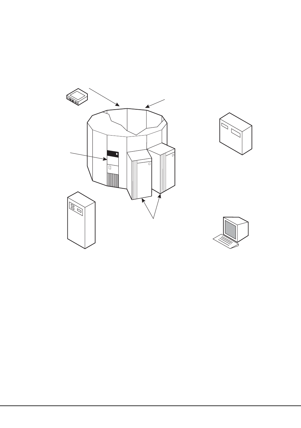
62 VM/HSC 6.0 System Programmer’s Guide
1st ed., 6/30/04 - 312579601
Command Functions
Command functions consist of real-time control of automated cartridge handling, dynamic
selection of HSC processing options, and various query operations.
Figure 6 illustrates the specific areas within a library where HSC commands enable you to
control processing.
CARTRIDGE CONTROL
ALLOC (MVS only)
DISMount
Display
Mount
MOVe
MNTD
SCRPOol
Warn
LSM
Display
MODify
VIew
OPTion (Viewtime)
LMU
Display
SWitch
Vary
CAP
CAPPref
Display
DRAin
EJect
ENter
MODify
OPTion
RELease
SENter
TAPE TRANSPORTS
ALLOC (MVS only)
CLean
DISMount
Mount
MNTD
HOST/HSC
CDs
COMMPath
Display
OPTion (Dialog)
RECover
RETry J3init (MVS/JES3 only)
SRVlev
Trace
TRACELKP
UEXIT (MVS only)
ACS
Display
SWitch CONSOLE
Display
OPTion
MONITOR (MVS only)
STOPMN (MVS only)
C29358
Figure 5. HSC Command Functions Overview

Chapter 2. Host Software Component Functions 63
1st ed., 6/30/04 - 312579601
Controlling LSM Operating Mode
The operating mode for any LSM is controlled by using the MODify command to place
the LSM online or offline. An LSM operating mode is a relationship between an LSM and
all attached hosts. The two LSM operating modes are:
• automatic – the LSM is online to all hosts.
• manual – the LSM is offline to all hosts.
When an LSM is online, the LSM is in the automatic mode, meaning that the robot is fully
operational. When an LSM is offline, the LSM is in manual mode.
Refer to the HSC Operator’s Guide, Chapter 4, ‘‘Managing Library Resources,’’ for
procedures describing how to operate an LSM in manual or automatic mode.
Controlling CAP Operating Mode
The operating mode for CAPs is controlled by the CAPPref and MODify commands. The
four CAP operating modes are:
• automatic – the user can enter cartridges into an LSM without using HSC commands
or utilities.
• manual – the user must issue HSC commands and utilities to use the CAP.
• online – the CAP is online to all hosts.
• offline – the CAP is offline to all hosts.
Refer to the HSC Operator’s Guide, Chapter 3, ‘‘Operating an Automated Cartridge
System,’’ for a description of CAP modes and Chapter 4, ‘‘Managing Library Resources,’’
for procedures describing how to operate an LSM in manual or automatic mode.
Viewing the Interior Components of an LSM
Should you have a need to determine the state of a tape transport or any other component
inside of an LSM, you can use the VIew command to ‘‘see’’ inside of an LSM for visual
inspection of a tape transport, pass-thru port, storage cell, CAP, or playground cell.
Using the VIew command offers benefits; you do not need to:
• vary tape transports offline
• modify the LSM offline
• physically open the LSM access door to inspect the inside of the LSM
• disable the LSM for minutes at a time.
Note: This feature is standard on a model 4410 (Cimarron) or 9310 (PowderHorn) LSM.
A 9360 (WolfCreek) LSM requires an optional vision system. The SL8500 library does
not provide viewing capability.

64 VM/HSC 6.0 System Programmer’s Guide
1st ed., 6/30/04 - 312579601
Using the VIew command to Inspect an LSM Component
When you issue the VIew command, you direct the vision system to focus on an item
inside of the LSM for a specified length of time. Upon entering the command, the
following events occur:
• A VIew request is sent to the controlling LMU.
• A WTOR is displayed on the console when the camera is in position; the message
indicates which camera/robot hand is focused on the specified object.
Note: If you respond to the message before the expiration of the requested time
interval, the VIew request is cancelled. Refer to the OPTion command and the
Viewtime parameter for controlling the view interval. The HSC Operator’s Guide,
Chapter 2, ‘‘Commands, Control Statements, and Utilities,’’ describes the operator
commands.
• The message on the console is DOMed.
• Optionally, a subtype 8 SMF record is written. The record includes the length of time
that the camera was held in a static position for this particular VIew command. Refer
to Appendix C, “Record Formats” on page 445 for more information on SMF
records.
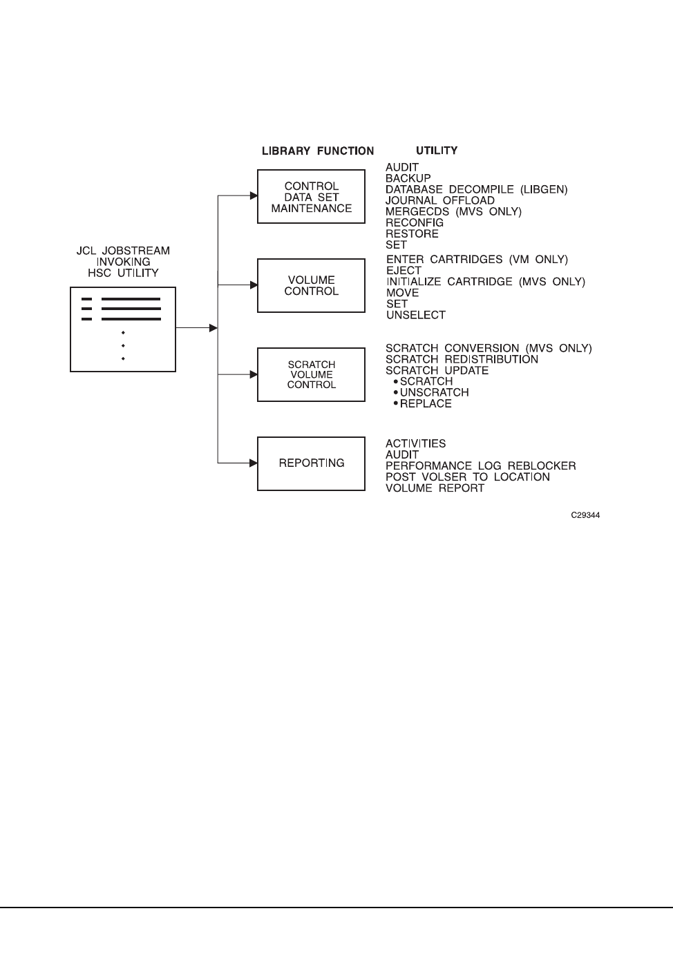
Chapter 2. Host Software Component Functions 65
1st ed., 6/30/04 - 312579601
Utility Functions
Utility functions provide control and recovery of library resources. In addition, reporting
of library and volume activity can be invoked using various HSC utilities.
Figure 7 illustrates the control concept provided by the various HSC utilities.
Refer to Chapter 4, “Utility Functions” on page 131 for detailed descriptive information
about all HSC utilities, including description, syntax and parameters, JCL requirements
and examples, and samples of output.
Figure 6. Utility Functions Overview

66 VM/HSC 6.0 System Programmer’s Guide
1st ed., 6/30/04 - 312579601
LMU Server Functions
LMU server functions control each of the Automated Cartridge Systems within a library.
Many of the LMU server functions are completely transparent to users. This section
contains information about LMU server tasks of which you should be aware.
Dual LMU Functionality
With dual LMU functionality, a switch happens when the LMU designated as the master
fails, or is forcibly switched by issuance of an operator command. The operator is also
notified when the LMU designated as the standby fails.
If the Master LMU Fails
When the master LMU fails:
• the standby LMU detects the failing master and informs the HSC
• the HSC reports the failure by issuing a message
• the HSC reacts as necessary to recover and continue processing mounts and
dismounts.
If the Standby LMU Fails
The standby LMU constantly polls the master. The master LMU acknowledges this
polling.
In the communications between the HSC and the master LMU, the master, as part of its
acknowledgment, informs the HSC of the status of the standby. The standby LMU is either
ready or not ready.
The master LMU thinks that the standby is ready if the standby has polled the master in
the required time interval. If the standby LMU has not polled the master in the required
time interval, the master informs the HSC that the standby is not ready.
The HSC issues an outstanding message. This informs the operator of the status change
(not ready) in the standby LMU.
Operator Control of LMUs
A library operator can control which LMU is operating with the SWitch command. When
the SWitch command is issued, all hosts connected to the ACS are affected.
If after entering a SWitch command, the new master LMU fails and the switchover does
not occur in 20 seconds, the HSC attempts to resume working with the old master. (The
HSC has been waiting for the standby LMU to take over as the master LMU, but the
switch did not take place.)
If the SWitch command fails, the system issues an error message. The operator can force
the completion of the command-generated switchover either by:
• manually re-IPLing the master LMU, or
• powering off the master LMU. 2

Chapter 2. Host Software Component Functions 67
1st ed., 6/30/04 - 312579601
LMU Switchover Messages
The HSC Messages and Codes Guide contains all the messages appropriate to the LMU
switchover process.
After an LMU Switch Occurs
After a switch of LMUs occurs and the LSMs have finished quick initialization
procedures, all cartridge motion requests are re-driven and completed. If a motion request
cannot be completed, the cartridge in question is made errant.
Note: ENter and EJect operations may need to be restarted after a switchover.
HSC/LMU Software Combinations
Table 4 describes the various possible combinations of HSC software with LMU
microcode and installed hardware. The table indicates valid combinations.
Table 4. HSC/LMU Validity Matrix
HSC
Version
LMU
Version
Number of
LMUs Powered
Up
Valid
Combination Functionality Available
1.2 +
ECap SPE 3.2
1 Yes New HSC features are available. Dual LMU
can be configured*, but switchover cannot
occur.
* Configuration of dual LMU is done by a StorageTek Customer Services Engineer (CSE).
2 Yes New HSC features are available. Dual LMU
must be configured*. Switchover can be
automated.
1.2 or later 3.6 or later
1 Yes New HSC features are available. Dual LMU
can be configured*, but switchover cannot
occur.
2 Yes New HSC features are available. Dual LMU
must be configured*. Switchover can be
automated.
2.0 or later 9315/30 1.0
or later.
1 Yes New HSC features are available. Dual LMU
can be configured*, but switchover cannot
occur.
2 Yes New HSC features are available. Dual
LMU must be configured*. Switchover can
be automated.
68 VM/HSC 6.0 System Programmer’s Guide
1st ed., 6/30/04 - 312579601
Adding New Stations to an ACS
The following is an example of JCL for the SET utility that can be used as a pattern for
adding new stations to an ACS without requiring a reconfiguration.
Note: Update LIBGEN control statements to make changes permanent. You do not have
to execute the Reconfig utility to implement these changes. Refer to “Reconfiguration
Utility” on page 225 for more information about reconfiguration.
JCL to Add New Stations to an ACS
Notes for the Example
1. The first SET control statement defines the listed stations for only one host.
Note: All stations must be specified (not just the new ones).
2. The second SET control statement defines the listed stations for all hosts.
Note: All stations must be specified (not just the new ones).
3. The following are installation dependent:
- SLSCNTL data set
- SLSCNTL2 data set
- station identifiers
- ACS numbers
-host IDs.
4. The standby CDS is not required for this JCL.
//HSCUPDAT JOB (acctno),’LMU STATIONS’,MSGCLASS=1,CLASS=A,
// MSGLEVEL=(1,1)
//STEP0 EXEC PGM=SLUADMIN
//* The following DD is the HSC STEP library
//STEPLIB DD DSN=SLS.PROD.LINKLIB,DISP=SHR
//SLSPRINT DD SYSOUT=*
//* The following DD statement identifies the HSC primary CDS
//SLSCNTL DD DISP=SHR,DSN=SLS.DBASE1
//* The following DD statement identifies the HSC primary CDS
//SLSCNTL2 DD DISP=SHR,DSN=SLS.DBASE2
//SLSIN DD *
SET SLISTATN(0CD,0CE,0D0,0D1) FORACS(0) FORHOST(HST1)
SET SLISTATN(0CD,0CE,0D0,0D1) FORACS(0)
//

Chapter 2. Host Software Component Functions 69
1st ed., 6/30/04 - 312579601
Reconstructing a LIBGEN
The Database Decompile (LIBGEN) utility can be used to reconstruct a LIBGEN,
reflecting the true configuration of your HSC subsystem if for some reason your LIBGEN
has been lost.
Refer to “Database Decompile (LIBGEN) Utility” on page 184 for details on how to use
the Database Decompile utility.

70 VM/HSC 6.0 System Programmer’s Guide
1st ed., 6/30/04 - 312579601
Dynamic LMU Connection
LMU network connections can be defined dynamically to TCP/IP addresses using the
LMUPATH and LMUPDEF control statements.
Note: For information on implementing TCP/IP connections, refer to the LMUPATH
and LMUPDEF control statements in Chapter 3, “HSC Control Statements and HSC
Start Procedure” and to display information about the LMUPDEF data set, refer to
Display LMUPDEF in the HSC Operator’s Guide.
In addition to the control statements, the following informational and procedural topics are
discussed in this section:
• security administration considerations
• recovery maintenance requirements
• HSC port number assignments
• multiple TCP/IP stack implications
• transitioning between 3270 and TCP/IP
• recovering TCP/IP communications
• configuring VM for TCP/IP support.
Recovery Maintenance Requirements
Two sets of PTFs must be applied to allow the recovery processes described in
“Recovering TCP/IP Communications” on page 73 to function correctly:
• for HSC 4.0, L1H10KE and L1H10LC
• for HSC 4.1, L1H10L4 and L1H10LE.
These PTFs contain HOLDDATA that describes new messaging and station status during
recovery.
For HSC release levels later than HSC 4.0 and 4.1, these enhancements are included in the
base FMID.
HSC Port Number Assignments
The 9330 TCP/IP LMU listens on ports 50001 through 50016. The port assignment used
by the HSC is determined by adding the host index number within the CDS to 50000, i.e.,
host index number + 50000
Users can find out the host index number of the system(s) running the HSC by entering:
Display CDS
Part of the output from this command displays hostids using this CDS. The first hostid in
the list represents host index number 1, the second host index number 2, and so forth.

Chapter 2. Host Software Component Functions 71
1st ed., 6/30/04 - 312579601
For example, if a user enters Display CDS and the following output appears
HOSTID---LEVEL!FLAG---DESCRIPTION---
HSTA 4.0.0 (F0) ACTIVE PRIMARY SECONDARY STANDBY
HSTB 4.0.0 (F0) ACTIVE PRIMARY SECONDARY STANDBY
HSTC 4.0.0 (F0) ACTIVE PRIMARY SECONDARY STANDBY
HSTD 4.0.0 (F0) ACTIVE PRIMARY SECONDARY STANDBY
then, HSTA is host index number 1, which when added to 50000 means that the HSC on
HSTA uses port number 50001, the HSC on HSTB uses 50002, the HSC on HSTC uses
50003, and the HSC on HSTD uses 50004.
Multiple TCP/IP Stack Implications
When multiple TCP/IP stacks run on the same host as the HSC, the TCP/IP stack used for
LMU communications must be identified to the HSC.
Modify the HSC JCL to include the SYSTCPD DD statement. This statement must
specify the TCPIP.DATA data set used by the TCP/IP stack for LMU communications.
The TCPIP.DATA data set contains configuration information required by the TCP/IP
client and server programs.

72 VM/HSC 6.0 System Programmer’s Guide
1st ed., 6/30/04 - 312579601
Transitioning Between 3270 and TCP/IP
A number of methods are available to move between 3270 station connections and TCP/IP
LMU network attachment. StorageTek recommends cycling the HSC as the preferred
process to transition between 3270 and TCP/IP. However, the following procedures
offer alternative ways to accomplish the transition.
Note: The host ACS client must be upgraded to VM 4.0 or higher and must be running
IBM TCP/IP.
3270 to TCP/IP
1. After the hardware modification to the LMU has been made to support network
communications, vary the stations offline.
Vary STation 028 OFFline
Notes:
1. Users can also vary the ACS offline.
Vary ACS 00 OFFline
2. Station addresses specified in the LIBGEN SLISTATN macro do not have to be
removed for the HSC to communicate to the LMU using TCP/IP.
2. Load the LMUPDEF statements containing the LMUPATH parameters that specify
the hostname or IP address for each ACS.
LMUPDEF DSN(‘xxx.xxx.xxx(xxx)’)
StorageTek recommends that the LMUPDEF statement be specified in the
initialization parameters, however, this statement can be issued from the console as
well.
3. Use the Vary ACS command to bring each ACS online. Message SLS0054I indicates
that the ACS is online. After all ACSs to be network-attached are online, the HSC is
ready for processing.
TCP/IP to 3270
1. Vary the ACS offline.
Vary ACS 00 OFFline
2. Load an LMUPDEF control statement that includes either an empty data set (no
statements) or a data set that only contains an OPTion TITLE statement.
3. Either vary the ACS online, or vary the 3270 station addresses online.

Chapter 2. Host Software Component Functions 73
1st ed., 6/30/04 - 312579601
Recovering TCP/IP Communications
StorageTek suggests either performing a normal HSC shutdown or changing the
HSC state to the base service level prior to recycling TCP/IP or taking TCP/IP down
for any extended period of time.
Note: Please refer to “Recovery Maintenance Requirements” on page 70 to see PTFs that
must be applied before recovery processes discussed in this section can be implemented.
Unlike 3270 station protocol, TCP/IP station protocol requires the socket interface to be
reopened (restarted) by the HSC before communication to the LMU can be reestablished.
If the LMU station connection is lost, the HSC begins network recovery to the station.
During recovery, the HSC continues trying to reestablish the connection between its
socket and the remote station socket every 10 seconds for 30 minutes. Once the network
problem is resolved, the next time the HSC attempts network connectivity, it reestablishes
communication to the LMU.
Note: When 30 minutes is exceeded, no further reconnection attempts are made, and
operator intervention is required.
In a dual LMU environment, users can switch to the standby station if other host
processing is not greatly impacted. If connectivity is lost to both LMU stations, network
recovery is simultaneous.
When the HSC detects TCP/IP interface errors or timeout conditions, message SLS6012E
is issued.
SLS6012E ACS AA recovery of network connection to station C...C is now
active
When the HSC successfully recovers network connectivity, message SLS6013I is issued
and all outstanding LMU requests are redriven.
SLS6013I ACS AA recovery of network connection to station C...C
successful
If the HSC network recovery times out, message SLS6014E is issued, the station is
considered in error, no further reconnection attempts are made, and operator intervention
is required.
SLS6014E ACS AA unable to reestablish connection to station C...C
Caution: During network recovery or timeout situations, only use the Display Acs
command to view ACS and station status. The Display Cap and Display LSM commands
involve LMU requests and will not execute.

74 VM/HSC 6.0 System Programmer’s Guide
1st ed., 6/30/04 - 312579601
Operator Intervention - Single LMU Configuration
If the HSC network recovery times out, the ACS is automatically changed to an offline
state and all outstanding LMU requests are purged. After troubleshooting the network
connection, vary the ACS online.
Vary ACS acs-id ONline
Note: During network recovery, the ACS can be forced offline, however, all
outstanding LMU requests are purged. StorageTek recommends that users allow the
HSC network recovery process to remain active and not to force the ACS offline.
Operator Intervention - Dual LMU Configuration
Communication Lost to Master LMU
If network recovery times out on the master LMU, and the HSC is still connected to the
standby LMU, the ACS is still considered in an online state. Issue the SWitch command to
make the current standby LMU the new master LMU.
SWitch Acs acs_id
The HSC redrives requests to the new master LMU.
Communication Lost to Standby LMU
If network recovery times out on the standby LMU, resolve the network problem and IPL
the standby LMU. After the IPL is complete, the master LMU notifies the HSC that the
standby LMU is now ready and network connectivity is reestablished with the standby.
Communication Lost to Both LMUs
If network recovery times out on both LMUs, the ACS is automatically changed to an
offline state and all outstanding LMU requests are purged. After the network problems are
resolved, vary the ACS online.
Note: When network recovery is active on the master and standby LMUs, the ACS
can be forced offline, however, all outstanding LMU requests are purged.
StorageTek recommends that users allow the HSC network recovery process to
remain active and not to force the ACS offline.

Chapter 2. Host Software Component Functions 75
1st ed., 6/30/04 - 312579601
Configuring VM for TCP/IP Support
The following items must be updated to allow VM to support TCP/IP station protocol.
• System Definition File
• System Profile File
• HSC Startup Job File
• LMUPATH Definition Data Set.
System Definition File (ACS SYSDEF)
To define the IUCV connection with the LMU communications component, add the
TCP/IP file statement to the ACS SYSDEF file.
FILE LCOMM IUCV <tcpip> DSN <tcpip>.LMU.COMM
where tcpip is the user ID of the TCP/IP service machine.
System Profile File (ACS SYSPROF)
Add the LMUPDEF command and control statement to the ACS SYSPROF file.
LMUPDEF <vaddr> DSN <dsname> VOL <volser>
where
vaddr is the virtual address of the data set that contains the LMUPATH
statements.
dsname is data set name.
volser is the volume serial number of the volume on which the data set resides.
HSC Startup Job File (ACS SLKJCL)
Add the LMUPDEF command and control statement to the ACS SLKJCL file.
LMUPDEF DSN(dataset.name) VOLUME(volser) UNIT(vaddr)
where
dataset.name is data set name of the volume.
volser is the volume serial number of the volume on which the data set resides.
vaddr is the virtual address of the data set that contains the LMUPATH
statements.

76 VM/HSC 6.0 System Programmer’s Guide
1st ed., 6/30/04 - 312579601
Initializing the LMUPATH Definition Data Set
The next three tasks apply to the LMUPATH definition data set.
Minidisk Statement for the LMUPATH Data Set
Add a minidisk statement to the directory entry for the STKACS userid. Refer to
“Define the ACS Service Machine” in the HSC Installation Guide for an example.
Minidisk Format
Format the minidisk as an OS or CMS RESERVED minidisk using the SLIMDISK
utility. Refer to “Allocation of OS-formatted Minidisk” and “Allocation of CMS
RESERVED Minidisk” in the HSC Installation Guide for more information.
Commands to Format OS Minidisk:
EXEC SLIMDISK <vaddr> <volser> (INIT
EXEC SLIMDISK <vaddr> <volser> <numcyls> 4080 80 DSN <dsname>
where
vaddr is the virtual address.
volser is the DASD volume serial number.
numcyls is the number of cylinders to allocate.
dsname is the data set name to assign to this space.
Commands to Format CMS Reserved Minidisk:
EXEC SLIMDISK CMSR <vaddr> <volser> 512 (INIT
EXEC SLIMDISK CMSR <vaddr> <volser> DSN <fname> <ftype>
where
vaddr is the virtual address.
volser is the DASD volume serial number.
fname is the file name of the data set.
ftype is the file type of the data set.

Chapter 2. Host Software Component Functions 77
1st ed., 6/30/04 - 312579601
LMUPATH Definition Data Set
Add the LMUPATH statements to the LMUPDEF data set using the ACS UTIL
VOLCOPY command.
Note: ACS UTIL VOLCOPY creates skeleton JCL that you modify to match your
configuration.
/JOB SLSXUTIL SLUGENER
/PARM RECCOPY
/FILE SYSPRINT DEV PRNT CLASS A
/FILE SYSUT2 DEV <vaddr> DSN <dsname>
/FILE SYSUT1 *
LMUPATH ACS(aa) LMUADDR(nnn.nnn.nnn.nnn)
LMUPATH ACS(aa) LMUADDR(nnn.nnn.nnn.nnn)
•
•
•
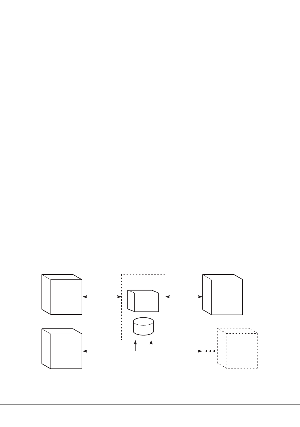
78 VM/HSC 6.0 System Programmer’s Guide
1st ed., 6/30/04 - 312579601
Communication Functions
HSC communication functions ensure that passing of pertinent information between HSC
components and hosts is accomplished successfully.
Host-to-Host Communications Services
The HSC permits you to select the hierarchy of methods used for host-to-host
communications. The communications services are designed to provide you with fail-safe
communications between HSC hosts in a data center complex.
Information Passed Between Hosts
The following kind of information is passed between hosts:
• control data set switch information
• CAP status information.
Types of Communications Services
Communications services that are available fall into three categories:
• Telecommunications access method through the ACF/VTAM network – This method
of host-to-host communications provides the highest performance and reliability.
• Communication through the LMU – This method of host-to-host communications is
a lower performance method than ACF/VTAM.
• Communication through the CDS – This method of host-to-host communications is a
lower performance method than either ACF/VTAM or LMU.
Figure 8 illustrates the available communication methods and relative hierarchy of the
methods.
HOST 1
LMU
VTAM
COMMUNICATION
METHOD
HOST n
CDS
HOST 0 HOST 2
C29348
Figure 7. HSC Communication Methods
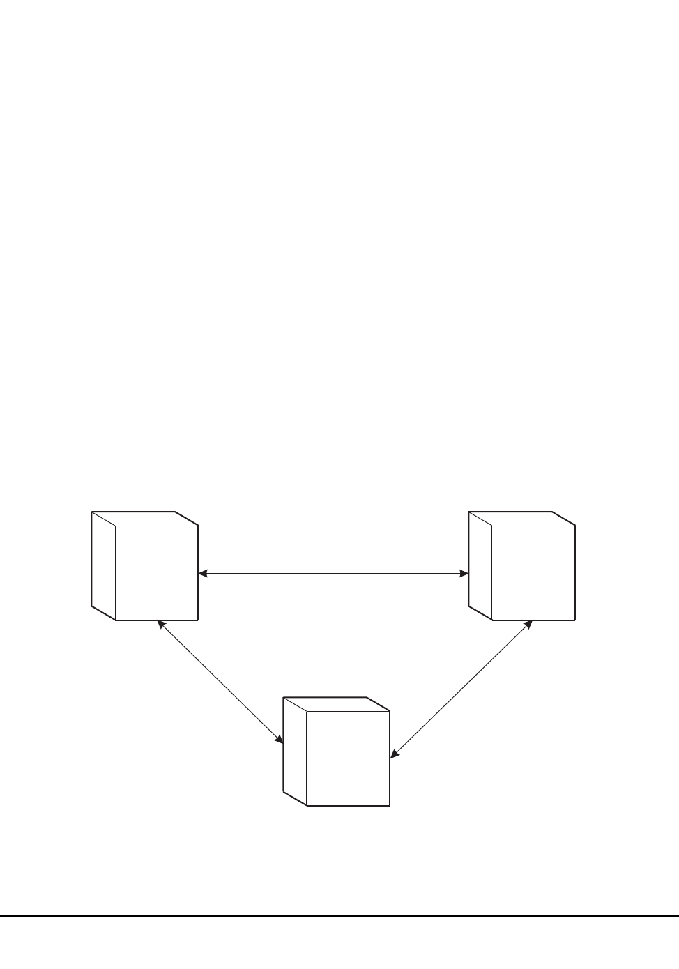
Chapter 2. Host Software Component Functions 79
1st ed., 6/30/04 - 312579601
How Communications Services are Set or Changed
Communications services are set or changed by the Communications Path (COMMPath)
command and control statement. This command specifies host, communication method,
LMU paths and VTAM path name for the associated host. The communication path
definitions can be modified at any time during library operation without terminating the
HSC.
The COMMPath command and control statement sets up a table of definitions for the host
that is executing the command. Each host’s table must contain a list of path definitions for
itself and a separate list for each defined host. Therefore, on each host, the command must
be issued once to define the paths for itself, once to define the paths for a second host,
once to define the paths for a third host, and so on, until all hosts are defined.
For example, the library is operating in an environment with three hosts: Host 0, Host 1,
and Host 2. The COMMPath command must be issued three times on each host. The table
of definitions for Host0 must contain a list of paths for Host 0, a list for Host 1, and a list
for Host 2. The same is true for Host 1 and Host 2.
For one host to communicate with another, they must have matching entries in their
respective lists of defined paths. The highest-performance method that is common to two
hosts is selected as the current method of communications between the two. A host can
use one method of communications with a second host, and a different method of
communications with a third host.
Figure 9 illustrates how different communication methods can be used between multiple
hosts.
C26184
CDS
COMMUNICATIONS LMU
COMMUNICATIONS
HOST 0
METHODS
VTAM
CDS
HOST 1
METHODS
LMU
CDS
HOST 2
METHODS
VTAM
LMU
CDS
VTAM
COMMUNICATIONS
EACH PAIR OF HOSTS COMMUNICATE USING THE
HIGHEST PERFORMANCE METHOD DEFINED TO BOTH
Figure 8. HSC Communication Methods Between Multiple Hosts

80 VM/HSC 6.0 System Programmer’s Guide
1st ed., 6/30/04 - 312579601
COMMPath can be specified by an operator as an operator command, or by a systems
programmer as a PARMLIB control statement. Before COMMPath is issued, all methods
of communications are set to CDS. Refer to ‘‘Communications Path (COMMPath)
Command and Control Statement’’ in the HSC Operator’s Guide for information on the
usage of the command.
It is recommended that host-to-host communications be defined in PARMLIB at startup.
The COMMPath operator command is best used to switch communications paths, or to
delete paths.
Displaying Current Status of Communication Services
The current status of the communications method is displayed by issuing the Display
operator command. Issuing the Display command, specifying the COMMPath parameter,
and optional HOSTid parameter results in a summary display at the console.
When issuing the command, individual hostids or all hosts can be specified. If you exclude
the HOSTid parameter in the command, a summary of current parameter settings for all
hosts is displayed in a message. If the HOSTid is specified as ‘‘*’’ the current settings are
displayed for the host from which the command is entered. If the ALL parameter is issued,
the current settings for all defined hosts are displayed.
The message provides a summary list for the current HSC host-to-host communications
parameters.
Switching Communications Paths
The performance ranking of the communications methods takes on meaning when it
becomes necessary to switch from one method to another because of a failure. A switch
can be initiated automatically by the HSC or dynamically by the operator using the
COMMPath command. The HSC issues a message to the console when a communications
path switch occurs, regardless of how it is initiated.
The HSC can initiate
• a lateral switch from one defined LMU path to another, or
• a downward switch from a higher performance method to any lower performance
method (VTAM to LMU, LMU to CDS, or VTAM to CDS).
The COMMPath command can initiate a switch to a higher, lower, or equivalent method.
Note: After an automatic downward switch has occurred, an upward switch can only be
accomplished using the COMMPath command.

Chapter 2. Host Software Component Functions 81
1st ed., 6/30/04 - 312579601
Software Requirements
The following software requirements apply:
• LMU 3.0 (or higher) or 9315/9330 1.0 (or higher) µ-software is required for a
multiple-level communications service.
• ACF/VTAM 3.2 (or higher) must be available to use the VTAM method of
communications.
Tape Management Interface
The tape management interface component provides you with the interface definitions that
can be used to interface a tape management system with the HSC.
Various functions are provided by the HSC to assist the tape management system (TMS)
with device allocation and cartridge mounting to optimize library cartridge handling, and
to minimize the need for operator intervention. The HSC provides the following assistance
to the tape management system.
• The HSC returns configuration information which describes the location of all
drives, the pass-thru connections between LSMs, and other information the TMS
might use to understand the library’s environment.
• The HSC returns volume location information including: whether the volume resides
in an ACS, in which LSM it is located, and the volume’s location in the LSM. This
information allows the TMS to determine whether the volume should be mounted on
an automated or a manual drive.
• The HSC returns a list of drives that are physically accessible to the volume. If a
scratch volume was specified, ordering is by LSM scratch counts. Drives in the same
LSM are considered to be closest; those accessed by one pass-thru event, the next
closest; and so forth. The list is ordered by proximity to the LSM containing the
volume. This information allows the TMS to match an ACS drive from this list to a
drive which the TMS determines to be available for mounting the cartridge.
• The HSC selects a scratch volume when requested, and returns volume information.
This allows the TMS to validate the volume’s scratch status before it is mounted. The
HSC also supports specifying, at mount time, that a scratch volume be used.
• The HSC mounts, dismounts, and ejects volumes at the request of the TMS. The
HSC returns status and success information about the operation.
• The TMS may direct the HSC to operate as if no operator were present. In this mode,
any operation which would require operator action, including responding to a
message, will be cancelled, and failure returned. The TMS may choose to retry the
operation.
Refer to the HSC Interface to Tape Management Systems Manual for more information.

82 VM/HSC 6.0 System Programmer’s Guide
1st ed., 6/30/04 - 312579601
Batch Application Program Interface (API)
The Batch API allows you to retrieve 2.0- and 2.1-level CDS information in batch mode.
The CDS specified as input to the request does not have to be active nor does it have to be
referenced by the HSC address space (the request executes in the user address space). In
addition, the HSC does not have to be active to submit the request. Refer to Appendix F,
“Batch Application Program Interface (API)” on page 629 for more information.
Chapter 3. HSC Control Statements and HSC Start Procedure 83
1st ed., 6/30/04 - 312579601
Chapter 3. HSC Control Statements and HSC Start
Procedure
Overview
This chapter discusses two kinds of control statements, PARMLIB (below) and definition
data set (refer to “Definition Data Set Control Statements” on page 103), and the HSC
Start procedure (refer to “Starting HSC Execution” on page 163). For more information
about HSC installation and initialization, refer to the HSC Installation Guide.
PARMLIB Control Statements
Parameter library (PARMLIB) control statements provide you a way, at HSC
initialization, to statically specify various operation parameters. Identifying your system
needs and then specifying various control statements permits you to tailor the HSC to the
needs of your data center.
Some PARMLIB options can be altered after HSC initiation with the HSC running. These
options can be changed using an appropriate operator command. With these options it is
not necessary to stop the HSC and restart it to initialize the new or changed options that
you want to specify. Those PARMLIB control statements that can be altered with the HSC
running are identified as PARMLIB commands or control statements in this chapter.
Any operator command can be specified as a PARMLIB control statement.
Note: Refer to “Syntax Flow Diagrams” on page 429 for the rules and conventions that
apply to command and control statement syntax.
Defining PARMLIB Control Statements
PARMLIB control statements are defined in a sequential data set or a single partitioned
data set (PDS) member that is opened when the HSC is initialized.
The PARMLIB control statements are invoked by specifying MEMBER(xx) or M(xx) on
the /PARM statement in the startup job. The suffix ‘‘xx’’ is concatenated with SLSSYS to
form a name. The name is used as the ddname in the startup job. The PARMLIB data set
(or PDS member) is opened and read to obtain the parameters for running the HSC
software.
Note: It is strongly recommended to use shared data sets for PARMLIB control
statements.
84 VM/HSC 6.0 System Programmer’s Guide
1st ed., 6/30/04 - 312579601
Processing PARMLIB Control Statements
PARMLIB control statements are processed at HSC initialization.
“Sample ACS SLKJCL File” on page 161 contains /FILE statements defining data sets
and members that contain PARMLIB control statement definitions.
Note: In the ACS SLKJCL example, ‘‘MEMBER(xx)’’ is the MEMBER parameter
described in “Defining PARMLIB Control Statements” on page 83.
Multiple PARMLIB data sets can be allocated. At HSC startup, members can be specified
at your discretion.
Examples of SLSSYSXX command lists and PARMLIB control statements are contained
in files SLSSYS00 COPY, SLSSYS12 COPY, and SLSSYS20 COPY.
Options Offered by PARMLIB Control Statements
The PARMLIB control statements offer various HSC operating options. At HSC
installation you identify the control statements to the HSC for those processes that you
want to tailor to your installation. The options are placed in the PARMLIB data set.
Options that you can control by using PARMLIB control statements are summarized
below. Refer to “Control Statement Syntax Conventions” on page 439 for information on
specifying control statements.
Note: PARMLIB control statements that apply only to system programmer tasks are
described in this guide. These include:
• Control Data Set definition
• EXECPARM Control definition
• Journal Data Set definition
• License key definition
• Reconfiguration definition
• Scratch Subpool definition.
The other command and control statements appear in the HSC Operator’s Guide.
CAP Preference Definition
This control statement and operator command defines an ordered list of CAPs that is
used by the library when cartridges are being entered or ejected. Refer to ‘‘CAP
Preference (CAPPref) Command and Control Statement’’ in the HSC Operator’s
Guide for detailed information.
Note: The CAPPref AUTO and MANual settings should not be placed in PARMLIB.
If these settings are used and the CAP is already in the selected mode, the command
is rejected without changing the preference value.
Control Data Set Definition
With this control statement and operator command, you specify the control data set
definitions and the number of control data sets that you want running. CDS definition
information is specified in the CDSDEF control statement. Refer to “CDS Definition

Chapter 3. HSC Control Statements and HSC Start Procedure 85
1st ed., 6/30/04 - 312579601
(CDSDEF) Control Statement” on page 87 for control statement syntax, parameter
information, and example statements.
Communications Path Definition
This control statement and operator command provides you a way to set the
communications path utilized in a multi-host environment. A hierarchy for
communications can be established. If a communications failure occurs, the
hierarchy defined ensures continued operation of HSC software and the
communications path. Refer to ‘‘Communications Path (COMMPath) Command and
Control Statement’’ in the HSC Operator’s Guide for more information.
EXECPARM Control Definition
The EXECPARM control statement provides an alternative method for specifying
GTF event and format IDs normally specified in the startup SLKJCL file. This
control statement also provides you with the option of displaying the command
prefix preceding WTO or WTOR messages. Refer to “EXECParm Control
Statement” on page 90 for control statement syntax, parameter information, and
example statements.
Journal Data Set Definition
In this control statement you specify the journal data set definitions. Journal
information is specified in the JRNDEF control statement. Refer to “Journal
Definition (JRNDEF) Control Statement” on page 92 for control statement syntax,
parameter information, and example statements.
License Key Information
This control statement is used to input license key information for the HSC. It is
placed in a data set or Partitioned Data Set member identified by an LKEYDEF
control statement in the HSC START procedure, and must be present for HSC to
initialize.
Mount/Dismount Processing Control
With the MNTD control statement and operator command, you can tailor the HSC’s
response to mount or dismount processing that occurs. For example, some of the
functions that you can control include:
• automatic or manual dismount and/or scratch
• console message display
• maximum count for use of cleaning cartridges
• device where scratch volumes mounted in a WolfCreek LSM are to be
dismounted or archived
• maximum number of pass-thrus allowed for a cartridge to be archived.
Refer to ‘‘MNTD (Mount/Dismount Options) Command and Control
Statement’’ in the HSC Operator’s Guide for control statement syntax,
parameter information, and example statements.

86 VM/HSC 6.0 System Programmer’s Guide
1st ed., 6/30/04 - 312579601
Option Control
The general purpose OPTion control statement and operator command provides you
methods to control the following:
• viewing time when using the VIew command
• issuance of a message if an attempt is made to enter duplicate volumes into a
library
• display of uppercase and lowercase characters output at the system console.
• maximum number of cartridges that can be ejected for one eject operation.
• volume processing associated with a specific CAP when the CAP is drained or
becomes unavailable before an eject operation completes.
Refer to ‘‘OPTION Command and Control Statement’’ in the HSC Operator’s Guide
for control statement syntax, parameter information, and example statements.
Reconfiguration CDS Definition
The RECDEF control statement is used during reconfiguration to specify the new
primary and secondary CDS definitions. Refer to “Reconfiguration CDS Definition
(RECDEF) Control Statement” on page 98 for control statement syntax, parameter
information, and example statements.
Scratch Subpool Control
Warning: If scratch pools are defined by this method and the TMS attempts to
define scratch pools with scratch pool indices, the TMS requests will return an
invalid return code. If VMTAPE is used as the tape management system, the
PARMLIB SCRPOol statements must be in the same alphanumeric order by name as
VMTAPE has them defined internally.
With this control statement, you can specify new scratch pools. Refer to “Scratch
Subpool Control Statement” on page 100 for control statement syntax, parameter
information, and example statements.
Control Statement Continuation Conventions
Control statements may be interspersed with comments designated by an asterisk (*) in
column one.
For definition data sets (VOLATTRs, UNITATTRs and TAPEREQs) comments must be
in the new format (/*...*/). Asterisk (*) comments are not allowed. A /*...*/ comment in
the first line is not required for definition data sets.
Refer to “Control Statement Syntax Conventions” on page 439 for more information.
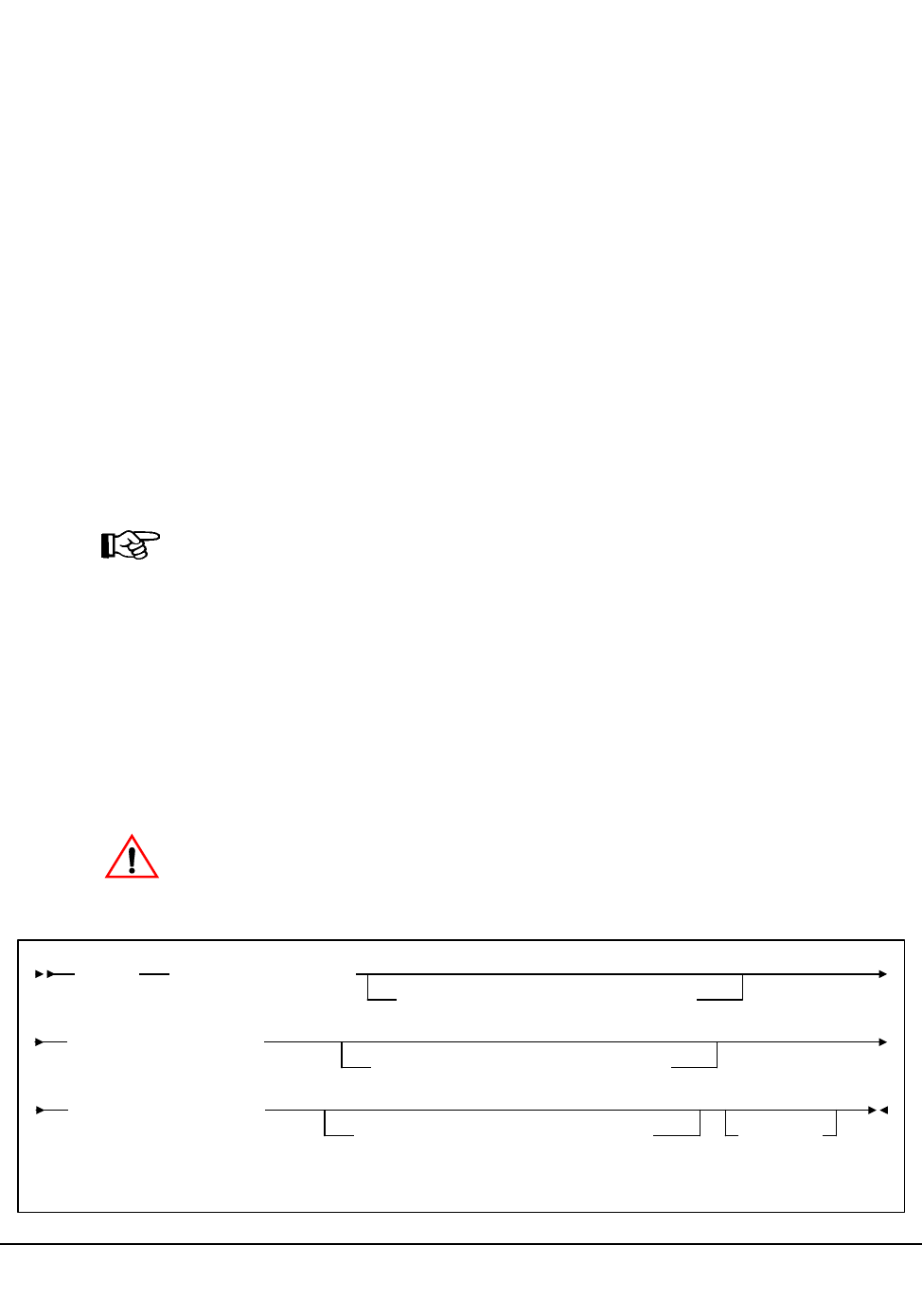
Chapter 3. HSC Control Statements and HSC Start Procedure 87
1st ed., 6/30/04 - 312579601
CDS Definition (CDSDEF) Control Statement
The CDSDEF control statement is required and provides static information to the HSC.
This information is used by the HSC at initialization and remains for the life of the HSC
execution. The primary, secondary, and standby control data sets are dynamically
allocated. The CDSDEF PARMLIB control statement defines which copies of the control
data set are used while the HSC is running.
Information used to build the SVC99 parameter lists is acquired from the parameter data
set.
If journaling is active, JRNDEF statements must be used (refer to “Journal Definition
(JRNDEF) Control Statement” on page 92 for more information).
Control information provided to the HSC by CDSDEF includes:
• the name(s) for HSC control data set(s)
• the DASD volume where the specified CDS resides
• the unitname for the SVC99 parameter list for CDS allocation
• switch information controlling the enabling of a standby CDS.
Notes:
• The number of CDS copies used by the HSC is dependent on the number of CDS
copies defined in the CDSDEF PARMLIB control statement. Control and journal
data sets may not be defined in SLKJCL; the CDSDEF statement must be in the
PARMLIB definitions. It is not determined by the LIBGEN SLIRCVRY macro
TCHNIQE parameter.
• The HSC uses all of the CDS copies defined in the CDSDEF control statement
(whether this includes more or less CDS copies than are specified by the TCHNIQE
parameter). However, if journaling is specified by the TCHNIQE parameter, journals
must be defined for successful HSC initialization.
Caution: Parameters specified for the CDS definition cannot be changed without a
complete restart of the HSC on all hosts.
Syntax
CDSDEF DSN1(dataset.name)
,VOL1(volser),UNIT1(unitname)
,DSN2(dataset.name)
,VOL2(volser),UNIT2(unitname)
,DSN2(dataset.name)
,VOL3(volser),UNIT3(unitname),DISABLE
CDSDEF

88 VM/HSC 6.0 System Programmer’s Guide
1st ed., 6/30/04 - 312579601
Control Statement Name
CDSDEF
initiates the control statement.
Parameters
DSNx
dataset.name is the name of an HSC control data set. At least one DSN parameter
must be specified, as many as three can be specified. If two data sets are specified,
then the volume inventory information on both copies is kept current, and these two
data sets are referred to as the primary and the secondary CDS.
If all three are specified, then two copies are kept current and the third data set is a
standby CDS which is enabled as the default condition. This standby CDS can be
disabled with the DISABLE parameter. In the case where a standby copy of the CDS
is being used, you do not need to specify which two of the three CDSs are the
primary and secondary copies. The HSC determines, based on last use, which two are
the correct copies to use during the initialization of the Control Data Set Services.
VOLx
optionally, volser is the volume serial number of the DASD volume where the
specified CDS resides. The VOL parameter must be specified in VM.
UNITx
optionally, unitname is used to specify the unit parameter in the SVC99 dynamic
allocation parameter list. The UNIT parameter must be specified in VM.
DISABLE
optionally, disables the standby CDS. If this parameter is not specified, the default is
to enable the standby CDS at HSC initialization.
If DISABLE is specified, initialization verifies the standby CDS by allocating,
opening, and reading the data set. The standby CDS is then closed and unallocated.
This process allows manual control over the use of the standby CDS during a control
data set switch situation.
If the standby CDS is enabled, the HSC automatically uses it for switching. If it is
disabled, it is not used. There is no enable parameter for CDSDEF, as the enable
condition is the default.
CDSDEF

Chapter 3. HSC Control Statements and HSC Start Procedure 89
1st ed., 6/30/04 - 312579601
Example
The following is an example of using the CDSDEF control statement.
Note: Control statements can only be continued if PARMLIB begins with a /*...*/
comment statement (see “Control Statement Syntax Conventions” on page 439).
CDSDEF DSN1(SLS.DBASE),VOL1(HSC101),UNIT1(501),+
DSN2(SLS.DBSEC),VOL2(HSC102),UNIT2(502),+
DSN3(SLS.DSTBY),VOL3(HSC103),UNIT3(503),+
DISABLE
CDSDEF
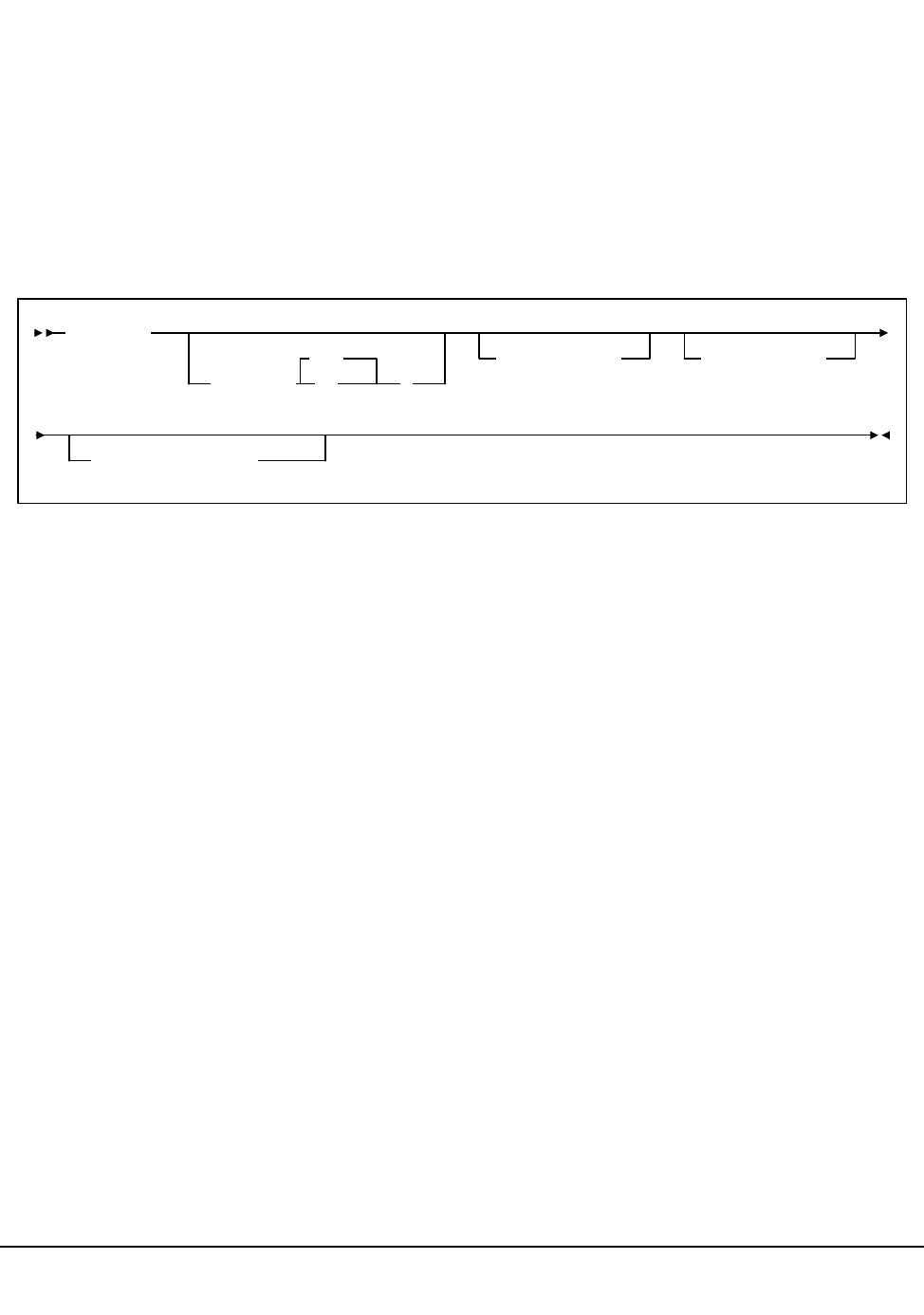
90 VM/HSC 6.0 System Programmer’s Guide
1st ed., 6/30/04 - 312579601
EXECParm Control Statement
The EXECParm control statement is an alternative method for specifying the GTF event
ID (Eid(gtfeid)) and GTF format ID (Fid(gtffid)). The EXECParm control statement also
provides a parameter that enables you to control display of the system command prefix
when messages are written to the operator at the system console. This parameter controls
the command prefix on WTO and WTOR messages.
Refer to “Creating an SLKJCL File for Starting the HSC” on page 157 for a description of
the start procedure and how it relates to EXECParm.
Syntax
Control Statement Name
EXECParm
initiates the control statement
Parameters
MSGPRFX
optionally, specifies control of whether the command prefix is to precede WTO or
WTOR messages to the operator.
Yes
indicates that the command prefix is to display preceding WTO or WTOR
messages to the operator.
No
indicates that the command prefix is not to display preceding WTO or WTOR
messages to the operator.
Eid
optionally, gtfeid specifies a GTF event ID.
/PARM Eid(user-specified-event-id) parameter is valid for use in the HSC startup
SLKJCL file as an alternative method of specifying the GTF event ID.
EXECParm
MSGPRFX( No
Yes
)
,Eid(gtfeid),Fid(gtffid)
,HOSTID(host-id)
EXECParm

Chapter 3. HSC Control Statements and HSC Start Procedure 91
1st ed., 6/30/04 - 312579601
Fid
optionally, gtffid specifies a GTF format ID.
/PARM Fid(user-specified-format-id) parameter is valid for use in the HSC startup
SLKJCL file as an alternative method of specifying the GTF format ID.
HOSTID
optionally, host-id specifies the system ID associated with the request to process the
EXECParm control statement.
Note: If the hostid specified does not match the host executing the command, the
command is ignored and no message is issued.
Example
The following example illustrates the use of the EXECParm control statement.
EXECParm Control Statement - Command Prefix Off
EXECP MSGPRFX(NO) E(086) F(23) HOSTID(HSC1)
EXECParm
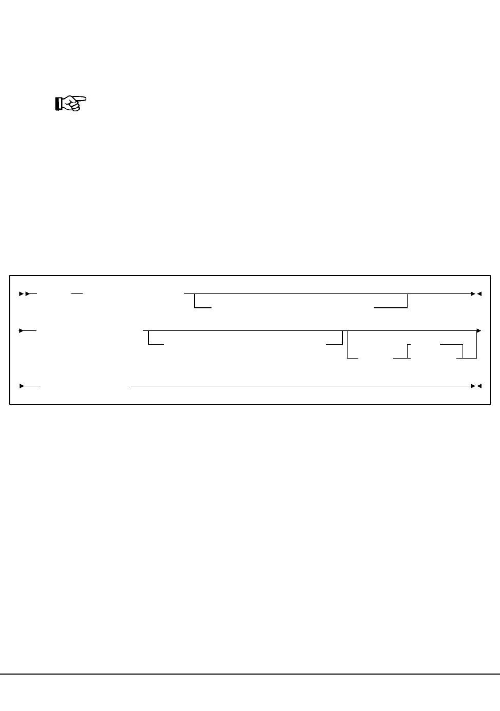
92 VM/HSC 6.0 System Programmer’s Guide
1st ed., 6/30/04 - 312579601
Journal Definition (JRNDEF) Control Statement
The JRNDEF control statement provides static information to the HSC. This information
is used by the HSC at initialization and remains for the life of the HSC execution. Control
information provided to the HSC by JRNDEF includes:
• the name for HSC journal data sets
Note: If your recovery technique involves using journals, both journal data sets are
required. HSC will not initialize if only one journal data set is provided.
• the DASD volume where the specified journal resides
• the unitname for the dynamic allocation parameter list for journal allocation
• journal full options.
In a multi-host complex, a separate JRNDEF statement is required for each host. Refer to
“CDS Definition (CDSDEF) Control Statement” on page 87 for information about
defining CDS files.
Syntax
Control Statement Name
JRNDEF initiates the control statement.
Parameters
DSNx
dataset.name is the name of an HSC journal data set. If journaling is active, each
HSC host that comes active must find a JRNDEF statement in PARMLIB with a
HOSTID that matches the system where it is running. Each JRNDEF statement must
specify two distinct journal DSNs.
Journal data sets cannot be shared between hosts.
VOLx
optionally, volser is the volume serial number of the DASD volume where the
specified journal resides. The VOL parameter must be specified in VM.
JRNDEF DSN1(dataset.name)
,VOL1(volser),UNIT1(unitname)
,DSN2(dataset.name)
,VOL2(volser),UNIT2(unitname)
,FULL(
Abend
Continue
,HOSTID(host-id)
JRNDEF
Chapter 3. HSC Control Statements and HSC Start Procedure 93
1st ed., 6/30/04 - 312579601
UNITx
optionally, unitname is used to specify the unit parameter in the SVC99 dynamic
allocation parameter list. The UNIT parameter must be specified in VM.
FULL
optionally, this parameter provides the following options:
Abend
the HSC internally abends if both journals fill to capacity before a CDS backup
is executed. This parameter is the default.
Continue
library operations in the complex continue to occur without the benefit of
journaling on any host.
Note: Once journaling is discontinued, the data contained in all journals and
off-loaded copies cannot be used for recovery purposes. However, by running
the BACKup utility, all journals are reset and journaling automatically becomes
active again.
HOSTID
host-id is the system ID associated with the journals specified with this control
statement. host-id must match the HOSTIDs defined by the SLILIBRY macro in the
LIBGEN for the subsystem.
Example
The following is an example of using the JRNDEF control statement.
Note: Control statements can only be continued if PARMLIB begins with a /*...*/
comment statement (see “Control Statement Syntax Conventions” on page 439).
JRNDEF DSN1(SLS.JRN01),VOL1(HSC101),UNIT1(510),+
DSN2(SLS.JRN02),VOL2(HSC102),UNIT2(511),+
FULL(CONTINUE),+
HOSTID(HSC1)
JRNDEF
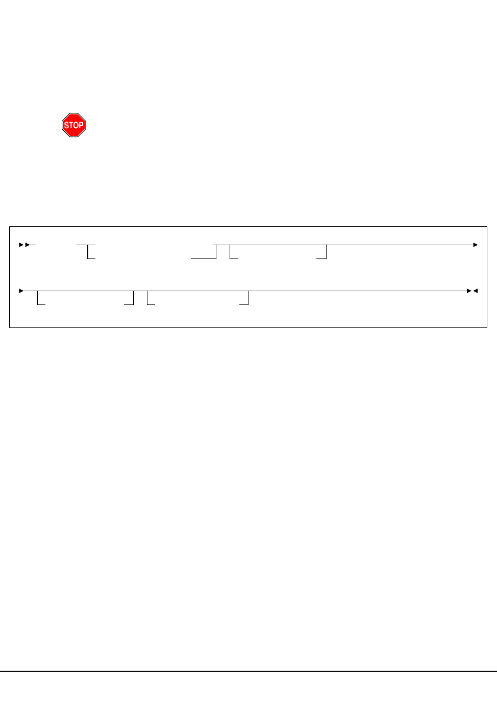
94 VM/HSC 6.0 System Programmer’s Guide
1st ed., 6/30/04 - 312579601
LKEYDEF Command and Control Statement
The LKEYDEF command/control statement retrieves LKEYINFO control statements
containing HSC license key information, and loads them into an address space where they
are available for retrieval by the HSC license key validation service.
Refer to the VM/HSC Installation Guide for more information about StorageTek license
keys.
Warning: The LKEYDEF control statement must be present in the HSC START
procedure prior to initialization.
The LKEYDEF operator command can be issued from the console without terminating the
HSC.
Syntax
Command Name
LKEYDEF
initiates the LKEYDEF command or control statement.
Parameter Descriptions
DATASET or DSN
Specifies the name of the data set containing the LKEYINFO control statement(s).
dataset-name
Indicates the name of the data set.
The definition data set can be a fixed length 80-byte sequential data set, or a
fixed length 80-byte member of a PDS. If the definition data set is a member of
a PDS, you must enclose the PDS and member name within single quotes.
VOLume
Optionally, specifies the volume on which the data set resides. This parameter is
required if the data set is not cataloged.
volser
Indicates the volume serial number.
DATASET(dataset.name)
DSN(dataset.name)VOLume(volser)
LKEYDEF
UNIT(unitname)HOSTID(host-id)
LKEYDEF

Chapter 3. HSC Control Statements and HSC Start Procedure 95
1st ed., 6/30/04 - 312579601
UNIT
Optionally, specifies the unit where the definition data set resides.
unitname
Indicates the unit name. If the definition data set is not cataloged or this
parameter is omitted, a unit name of SYSDA is the default.
HOSTID
Optionally, limits the execution of this command or control statement to the
specified hosts.
host-id
Specifies the name of one or more hosts from which to execute this command
or control statement.
Example
In the following example, the LKEYDEF control statement specifies that HSC license key
information is retrieved from the data set MY.LKEYINFO.FILE during initialization.
LKEYDEF DSN(MY.LKEYINFO.FILE)
LKEYDEF
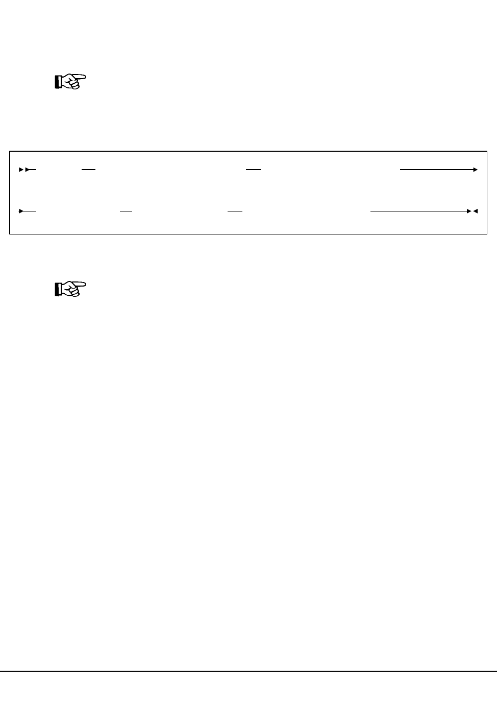
96 VM/HSC 6.0 System Programmer’s Guide
1st ed., 6/30/04 - 312579601
License Key Information (LKEYINFO) Control Statement
The LKEYINFO control statement is used to input license key information for the HSC.
It is placed in a data set or Partitioned Data Set member identified by an LKEYDEF
control statement in the HSC START procedure, and must be present for HSC to initialize.
Note: Refer to the VM/HSC Installation Guide for more information about configuring
your HSC license key.
Syntax
Parameter Descriptions
Note: All parameters must be entered exactly as received from StorageTek.
PRODuct
Specifies the product and release to which the license key applies.
product-identifier
Indicates the product identifier. For HSC 6.0, the product identifier is
VER0600.
CUSTomer
Specifies the customer name as received from StorageTek. A maximum of 20
characters can be entered for the customer name.
customer-name
Indicates the customer name.
SITEno
Specifies the site number as received from StorageTek.
nnnnnnn
Indicates the site number.
EXPRdate
Specifies the expiration date of the license key as received from StorageTek.
yyyyddd
Indicates the expiration date.
LKEYINFO PRODuct(product_identifier)CUSTomer('customer_name')
SITEno(nnnnnnn)EXPRdate(yyyyddd)KEY(license_key_string)
LKEYINFO

Chapter 3. HSC Control Statements and HSC Start Procedure 97
1st ed., 6/30/04 - 312579601
KEY
Specifies the license key string as received from StorageTek.
license-key-string
Indicates the license key string.
Examples
In the following example, the LKEYINFO control statement is used to input HSC license
key information as received from StorageTek.
LKEYINFO PROD(VER0600) -
CUST(‘CUSTOMER NAME’) -
SITE(12345) -
EXPRD(2004365) -
KEY(DKEEXEDERTB3466)
LKEYINFO
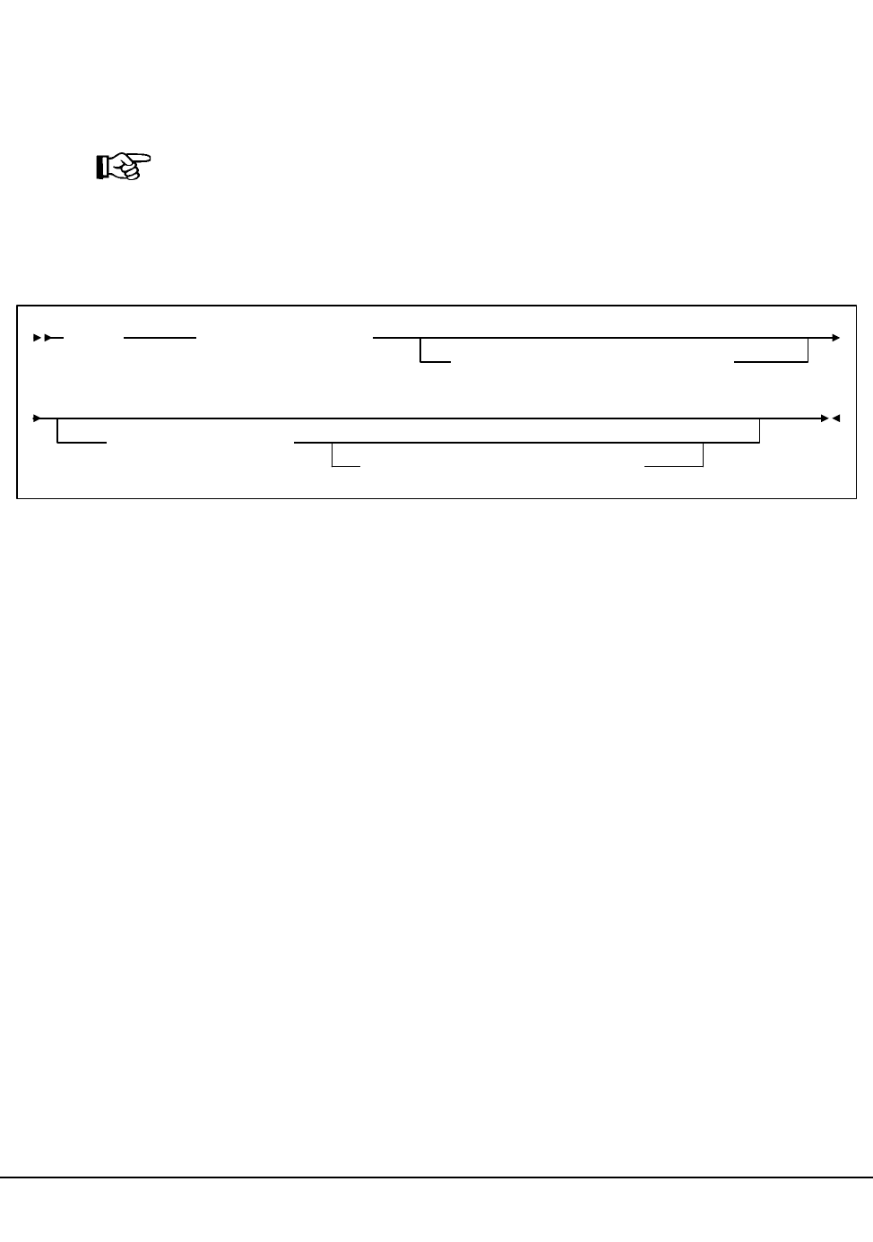
98 VM/HSC 6.0 System Programmer’s Guide
1st ed., 6/30/04 - 312579601
Reconfiguration CDS Definition (RECDEF) Control Statement
The RECDEF control statement, in combination with the CDSDEF control statement
(refer to “CDS Definition (CDSDEF) Control Statement” on page 87), defines which CDS
copies are to be used when running the Reconfiguration utility. CDSDEF specifies the old
input copies of the CDS; RECDEF the new copies.
Note: RECDEF parameters replace the DBPRMNEW and DBSHDNEW DD statements
used in previous releases. A new standby CDS created by the SLICREAT program (refer
to Chapter 7, ‘‘Allocating and Initializing Control Data Sets’’ in the HSC Installation
Guide) is not affected by reconfiguration. It becomes valid once it is enabled by the HSC.
Syntax
Control Statement Name
RECDEF
initiates the control statement.
Parameters
DSNx
dataset.name is the name of a newly created HSC CDS. At least one DSN parameter
must be specified; as many as two can be specified. The first DSN becomes the
primary CDS. If specified, the next DSN is created as an identical copy of the
primary CDS.
RECDEF DSNs are input for the first HSC initialization as CDSDEF control
statements. DSNs can be entered in any order whether or not this is the first
initialization. Order is not important, since all copies are identical after the
reconfiguration and controlling information is kept in each CDS for subsequent runs.
VOLx
optionally, volser is the volume serial number of the DASD volume where the
specified CDS resides. The VOL parameter must be specified in VM.
UNITx
optionally, unitname is used to specify the unit parameter in the SVC99 dynamic
allocation parameter list. The UNIT parameter must be specified in VM.
RECDEF DSN1(dataset.name)
,VOL1(volser),UNIT1(unitname)
,DSN2(dataset.name)
,VOL2(volser),UNIT2(unitname)
RECDEF

Chapter 3. HSC Control Statements and HSC Start Procedure 99
1st ed., 6/30/04 - 312579601
Example
The following is an example of using the RECDEF control statement.
Note: Control statements can only be continued if PARMLIB begins with a /*...*/
comment statement (see “Control Statement Syntax Conventions” on page 439).
RECDEF DSN1(SLS.DBASE),VOL1(HSC101),UNIT1(501),+
DSN2(SLS.DBSEC),VOL2(HSC102),UNIT2(502)
RECDEF
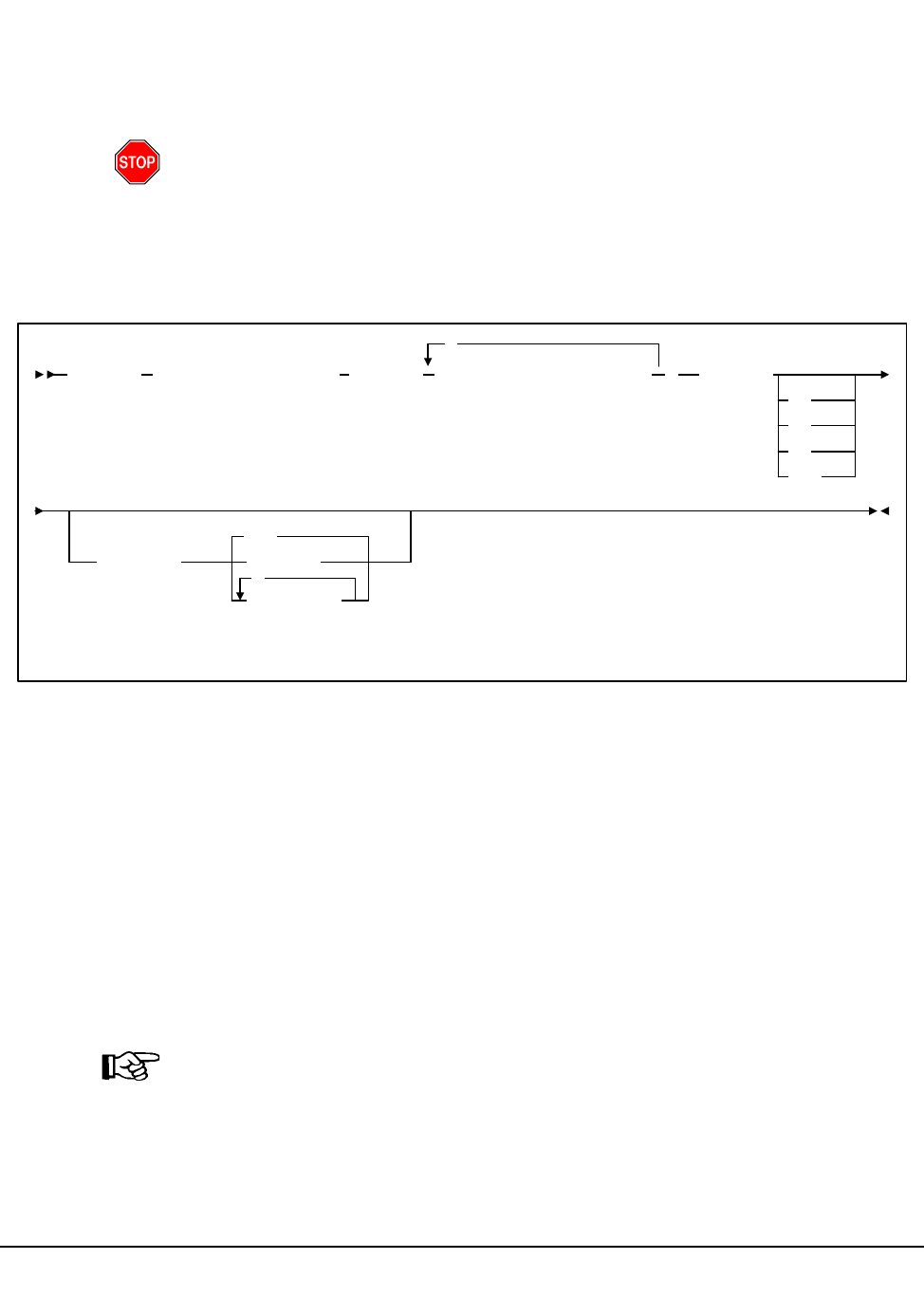
100 VM/HSC 6.0 System Programmer’s Guide
1st ed., 6/30/04 - 312579601
Scratch Subpool Control Statement
The scratch subpool control statement provides you with control of the scratch volume
activity in a library. Refer to “Scratch Subpool Management” on page 44 for more
information relating to this control statement.
Warning: If scratch pools are defined by this method and the TMS attempts to define
scratch pools with scratch pool indices, the TMS requests will return an invalid return
code. If VMTAPE is used as the tape management system, the PARMLIB SCRPOol
statements must be in the same alphanumeric order by name as VMTAPE has them
defined internally.
Syntax
Control Statement Name
SCRPOol
control statement identifier.
Parameters
Subpool information is defined in PARMLIB as individual control statements using the
following parameters.
NAME
specifies the name of the subpool. A maximum of 13 characters is allowed; blank
spaces are not permitted.
Note: If scratch subpools are defined using the TMI, the scratch subpool name may
be omitted. If the subpool name is not provided by the TMI, the subpool index is
used as the name. The subpool index is converted to three EBCDIC decimal digits
and placed in the leftmost three positions of the subpool name.
SCRPOol NAME(subpool-name),RANGE( range-start-range-end ),LABEL(
SL
NL
AL
NSL
,HOSTID(
,
ALL
host-id
host-list
,
SCRPOol

Chapter 3. HSC Control Statements and HSC Start Procedure 101
1st ed., 6/30/04 - 312579601
RANGE
range specifies the volume serial numbers which the subpool represents. Range start
and end values are separated by a single dash (-). Multiple ranges may be specified
separating each range by commas.
Notes:
1. The range of volume serial numbers must be unique for each subpool; that is, a
volume serial number cannot be used in more than one subpool range.
2. Make sure when you are coding multiple ranges of tapes that you do not specify
the RANGE parameter on different SCRPOol control statements. If more than
one SCRPOol statement has been specified, the HSC reads only the last
RANGE setting it encounters and loads only that range. All other ranges are
ignored.
StorageTek recommends that you specify multiple ranges, separated by
commas, on one SCRPOol control statement if possible.
LABEL
type specifies the label type associated with the applicable subpool. Types include:
SL
standard label
NL
no label
AL
ANSI label
NSL
nonstandard label
HOSTID
optionally, defines the hosts that are valid for this subpool. Multiple host-lists may be
specified, separating each host-list value with a comma. Default HOSTID is ALL. If
you need to define the same subpool name on some but not all hosts, you may
duplicate the SCRPOol statement changing the HOSTID parameter as necessary (see
examples). Optionally, you may use separate PARMLIB data sets for each host, but
this is not recommended.
SCRPOol

102 VM/HSC 6.0 System Programmer’s Guide
1st ed., 6/30/04 - 312579601
Example
The following is an example of using the Scratch Subpool control statement.
Other Methods of Controlling Scratch Subpools
There are other ways to control scratch volumes and scratch subpools in the library. The
following are additional methods that may be used:
• Display SCRatch command
• Display command with THReshld parameter
• ENter command specified with SCRatch parameter
• SCREdist utility with SUBpool and BALtol parameters
• EJect command with SCRTCH SUBpool parameters
• Mount command with SCRTCH SUBpool parameters
• Warn command with SCRatch SUBpool and THREShold parameters
• Tape management system (TMS) interface.
Refer to the HSC Operator’s Guide for more information.
SCRPO NAME(SITE1),RANGE(100000-200000,300000-400000),LABEL(SL)
SCRPO NAME(SITE2),RANGE(500000-540072),LABEL(NL),HOSTID(HSC1)
SCRPO NAME(SITE3),RANGE(540081-610094),LABEL(NSL)
SCRPO NAME(SITE4),RANGE(AP1000-AP1999),LABEL(SL),HOSTID(HSC1,HSC6)
SCRPOol

Chapter 3. HSC Control Statements and HSC Start Procedure 103
1st ed., 6/30/04 - 312579601
Definition Data Set Control Statements
Definition data sets contain the control statements used to define tape data set storage
policies to the HSC. A definition data set must be sequential (it may be a partitioned data
set [PDS] member) with any valid record format (RECFM). The syntax rules for the HSC
PARMLIB data set designated by SLSSYSxx apply to the statements contained in a
definition data set, except that comment statements with an asterisk in column one are not
allowed. Refer to “Control Statement Syntax Conventions” on page 439 for information
about PARMLIB syntax rules.
Each of the following commands cause the HSC to open a definition data set and load its
specified attributes:
• LMUPDEF (for LMUPATH)
• SCRPDEF (for SCRPOol)
• TREQDEF (for TAPEREQs)
• UNITDEF (for UNITATTRs)
• VOLDEF (for VOLATTRs).
The user can specify LMUPDEF, SCRPDEF, TREQDEF, UNITDEF, and VOLDEF
control statements either in the HSC PARMLIB data set to load the definition data sets at
startup, or issue them as operator commands to dynamically load the data sets without
stopping the HSC. The LMUPDEF, SCRPDEF, TAPEREQ, UNITATTR, and VOLATTR
statements contained in a definition data set are in effect only on the host that opens the
data set. They are not broadcast or propagated to other hosts, and are not maintained
across HSC stops and starts. The definition data sets must be opened each time the HSC is
restarted.
LMU path (LMUPATH), scratch subpool (SCRPOol), tape request attribute (TAPEREQ),
unit attribute (UNITATTR), and volume attribute (VOLATTR), statements may be placed
in the same definition data set or in different data sets, depending on your site
requirements. Each data set may also contain an OPTion TITLE statement with an
identifying string.
If the HSC encounters any other statements when it opens a definition data set, error
messages are issued, the statements are ignored, the definition data set is not loaded,
and definition data set processing terminates. The user must correct the problem
statements and reload the data set.
If a single data set contains TAPEREQ, UNITATTR, and VOLATTR statements, the HSC
must open the data set three times: once in response to a TREQDEF command, again in
response to UNITDEF, and a third time in response to VOLDEF. Each command uses only
the statements that apply.

104 VM/HSC 6.0 System Programmer’s Guide
1st ed., 6/30/04 - 312579601
Options Offered by Definition Data Set Control Statements
The following definition data set control statements are included in this chapter:
OPTion TITLE
This control statement allows you to specify a string that identifies a definition data
set. Refer to “OPTion TITLE Control Statement” on page 113 for control statement
syntax, parameter information, and example statements.
LMU Path
The LMUPATH control statement defines network LMU attachments. Refer to
“LMUPATH Control Statement” on page 108 for control statement syntax,
parameter information, and example statements.
LMU Parameter Definition
The LMUPDEF command and control statement identifies the definition data set
where network LMU network attachment statements reside (see LMUPATH).
LMUPDEF can be issued either in PARMLIB or as an operator command. Refer to
“LMUPDEF Command and Control Statement” on page 110 for control statement
syntax, parameter information, and example statements.
Scratch Subpool Parameter Statement Definition
The SCRPDEF command and control statement identifies the definition data set
where scratch subpool parameter statements reside (see Scratch Subpool Control
Statement). SCRPDEF can be issued either in PARMLIB or as an operator
command. Refer to “Scratch Subpool Definition (SCRPDEF) Command and Control
Statement” on page 115 for control statement syntax, parameter information, and
example statements.
Tape Request
The TAPEREQ control statement specifies tape request attributes. Refer to “Tape
Request (TAPEREQ) Control Statement” on page 118 for control statement syntax,
parameter information, and example statements.
Tape Request Definition
The TREQDEF command and control statement identifies the definition data set
where the tape request attributes reside (see TAPEREQ). TREQDEF can be issued
either in PARMLIB or as an operator command. Refer to “Tape Request Definition
(TREQDEF) Command and Control Statement” on page 133 for control statement
syntax, parameter information, and example statements.
Unit Attribute
The UNITATTR control statement specifies unit attributes. Refer to “Unit Attribute
(UNITATTR) Control Statement” on page 136 for control statement syntax,
parameter information, and example statements.
Unit Attribute Definition
The UNITDEF command and control statement identifies the definition data set
where the unit attributes can be found (see UNITATTR). UNITDEF can be issued
either in PARMLIB or as an operator command. Refer to “Unit Attribute Definition

Chapter 3. HSC Control Statements and HSC Start Procedure 105
1st ed., 6/30/04 - 312579601
(UNITDEF) Command and Control Statement” on page 140 for control statement
syntax, parameter information, and example statements.
Volume Attribute
The VOLATTR control statement specifies tape volume attributes. Refer to “Volume
Attribute (VOLATTR) Control Statement” on page 143 for control statement syntax,
parameter information, and example statements.
Volume Attribute Definition
The VOLDEF command and control statement identifies the definition data set
where the tape volume attributes can be found (see VOLATTR). VOLDEF can be
issued either in PARMLIB or as an operator command. Refer to “Volume Attribute
Definition (VOLDEF) Command and Control Statement” on page 154 for control
statement syntax, parameter information, and example statements.
Defining LMU Network Connections
LMUPATH statements allow users to define LMU network TCP/IP attachments. Network
addresses can be specified by host name or LMU IP address.
Defining Tape Request Attributes (TAPEREQ)
TAPEREQ statements describe the media type and recording technique to be used for a
particular data set.
TAPEREQ parameters are divided into selection criteria (inputs) and result criteria
(outputs). Selection criteria include:
• job name
•step name
• program name (MVS JES2 only)
• data set name
• expiration date or retention period (MVS JES2 only)
• volume type requested (specific or nonspecific).
Result criteria include:
• media type
• recording technique
•model
• subpool.
Collections of data sets with common characteristics can be identified in a single
TAPEREQ statement by specifying wild card characters. For example, if all data sets
residing on ECARTs are identified with an ‘‘L’’ as the first character of the data set name,
an ‘‘L**’’ could be specified to identify all these data sets in a single TAPEREQ
statement.
The TREQDEF command causes the HSC to open the definition data set containing the
TAPEREQ statements. See “Tape Request Definition (TREQDEF) Command and Control
Statement” on page 133 and “Tape Request (TAPEREQ) Control Statement” on page 118
for descriptions of syntax and parameters.

106 VM/HSC 6.0 System Programmer’s Guide
1st ed., 6/30/04 - 312579601
Defining Unit Attributes (UNITATTR)
UNITATTR statements describe the recording technique attributes of library and
nonlibrary transports. Transports are described by:
• unit address
• transport model number.
To allow the HSC to operate correctly, the user must specify UNITATTR statements
for all nonlibrary transport models that appear to the operating system as 3490E-type
and 3590-type devices. For library devices, the model type is determined by the LMU.
Refer to “Unit Attribute (UNITATTR) Control Statement” on page 136 for more
information.
Collections of transports with common characteristics can be identified with a single
UNITATTR statement by specifying a list of unit addresses, range of addresses, or
multiple ranges of addresses.
The UNITDEF command causes the HSC to open the definition data set containing the
UNITATTR statements. See “Unit Attribute Definition (UNITDEF) Command and
Control Statement” on page 140 and “Unit Attribute (UNITATTR) Control Statement” on
page 136 for descriptions of syntax and parameters.
Defining Volume Attributes (VOLATTR)
VOLATTR statements describe the media type and recording technique attributes of
cartridge tape volumes.
Volumes are described by:
• volume serial number (VOLSER)
• media type
• recording technique.
To allow the HSC to operate correctly, the user must define VOLATTR statements
for all ECART, ZCART, helical, 9840/T9840B (STK1), and T9940A media. Volumes
not defined by VOLATTRs are presumed to be standard capacity cartridges.
Note: Alternatives to defining VOLATTR statements are available. Refer to “Volume
Attribute (VOLATTR) Control Statement” on page 143 for more information.
Collections of cartridges with common attributes can be identified in a single VOLATTR
statement by specifying ranges and lists of VOLSERs, or using wild card characters.
Scratch counts are based entirely on VOLATTR information. Accurately defined
VOLATTR control statements are critical for correct processing of nonspecific
volume requests.
For specific mounts, the actual media type, as determined by the LMU, overrides
what is specified in the VOLATTR.

Chapter 3. HSC Control Statements and HSC Start Procedure 107
1st ed., 6/30/04 - 312579601
The VOLDEF command causes the HSC to open the definition data set containing the
VOLATTR statements. See “Volume Attribute Definition (VOLDEF) Command and
Control Statement” on page 154 and “Volume Attribute (VOLATTR) Control Statement”
on page 143 for descriptions of syntax and parameters.
Identifying the Definition Data Sets (OPTION TITLE)
The OPTion TITLE control statement places an identifying string in a definition data set to
describe the contents of the data set. See “OPTion TITLE Control Statement” on page 113
for descriptions of syntax and parameters.
Control Statement Continuation Conventions
Control statements may be interspersed with comments designated by an asterisk (*) in
column one.
For definition data sets (VOLATTRs, UNITATTRs and TAPEREQs) comments must be
in the new format (/*...*/). Asterisk (*) comments are not allowed. A /*...*/ comment in
the first line is not required for definition data sets.
Refer to “Control Statement Syntax Conventions” on page 401 for more information.
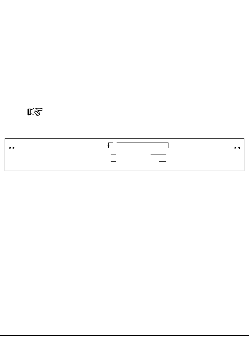
108 VM/HSC 6.0 System Programmer’s Guide
1st ed., 6/30/04 - 312579601
LMUPATH Control Statement
The LMUPATH control statement allows users to define network LMU attachments.
LMUPATH statements are read from the definition data set specified by the LMUPDEF
command. The LMUPATH statement must be placed in the definition data set; it cannot be
issued as an operator command.
Note: Users can find additional important TCP/IP-related information by referring to
“Dynamic LMU Connection” on page 70. To display the LMUPDEF data set, refer to
Display LMUPDEF in the HSC Operator’s Guide.
LMUPATH Usage
LMUPATH statements define the TCP/IP addresses used to communicate between an
HSC on a host and the LMU for a specific ACS. Up to two addresses can be specified for
each ACS, however, a second address indicates a dual LMU environment.
Note: TCP/IP must be initialized prior to bringing the HSC to the full service level.
Syntax
Control Statement Name
LMUPATH
initiates the LMUPATH control statement.
Parameters
ACS
specifies the ACS name.
aa
specifies the hexadecimal ACSid value (00 through FF) to identify the LMU
used to communicate with an HSC.
,
ACS(aa)LMUADDR(LMUPATH
lmu_hostname
nnn.nnn.nnn.nnn
)
LMUPATH

Chapter 3. HSC Control Statements and HSC Start Procedure 109
1st ed., 6/30/04 - 312579601
LMUADDR
identifies an LMU by IP address or host name for each ACS. To designate a single
LMU environment, specify one IP address or host name. To specify a dual LMU
environment, users can enter an additional IP address and/or host name.
Note: A maximum of two addresses can be specified.
Users can intermix host name and IP addresses in one LMUPATH control statement.
Each parameter entered must represent a different IP address.
lmu_hostname
defines a host name for the TCP/IP connection. The host name can be up to 24
characters long. The first character must be alphabetic.
Note: This option is not supported in VM.
nnn.nnn.nnn.nnn
defines an IP address for the LMU.
Example
The following example shows multiple LMUADDR parameters consisting of an IP
address and a hostname. In this case, the second parameter, LMU01, indicates a dual LMU
environment.
Note: The host name parameter shown in this example (LMU01) is not supported in VM.
LMUPATH ACS(00) LMUADDR(123.456.789.012,LMU01)
LMUPATH

110 VM/HSC 6.0 System Programmer’s Guide
1st ed., 6/30/04 - 312579601
LMUPDEF Command and Control Statement
The LMUPDEF command and control statement is used to specify the definition data set
that contains network LMU attachment (LMUPATH) statements. The data set must be a
sequential or a partitioned data set (PDS) with any valid record format (RECFM). Also,
the data set must contain one or more LMUPATH statements.
The LMUPDEF statement can be specified in PARMLIB, or it can be issued as an
operator command to dynamically load or reload LMUPATH parameters. (Refer to
‘‘PARMLIB Control Statements’’ in the HSC Installation Guide for an explanation of
PARMLIB.)
If a definition file is changed by a LMUPDEF operator command, and if the change is to
be permanent, you must update PARMLIB before restarting the HSC. If the definition file
is to be modified for a given shift or application, remember that the new definition remains
in effect until another definition is loaded or the HSC is recycled. The definition file then
reverts to the PARMLIB specification. Thus, LMUPDEF can be used to temporarily
change a definition file.
Definition commands issued on one host are in effect only on that host. If different hosts
use the same definition data set, the LMUPATH parameter statements are shared by those
hosts.
Notes:
1. Users can find additional important TCP/IP-related information by referring to
“Dynamic LMU Connection” on page 70. To display the LMUPDEF data set, refer
to Display LMUPDEF in the HSC Operator’s Guide.
2. When the LMUPDEF command is issued, if the definition data set contains errors, an
HSC message provides the parameter in error, a description of the problem, and the
line number where the error occurred. If the definition data set contains errors, none
of the attributes specified in the LMUPATH control statement(s) will be loaded (put
into effect). Message SLS1627I is displayed if errors are encountered. If 50 errors are
encountered, the remainder of the data set is not checked. Correct the problem and
reissue the command.
3. The LMUPDEF command and control statement executes at both base and full
service levels of the HSC.
4. If you issue multiple LMUPDEF commands or statements, the last one processed is
currently active. You can determine which LMUPDEF statement is active by
entering the Display LMUPDEF command.
5. In order for the new IP addresses to take effect, users must first establish IP addresses
with the LMUPDEF command. Next, vary the ACS(s) offline and then online, using
the Vary ACS operator command.
LMUPDEF
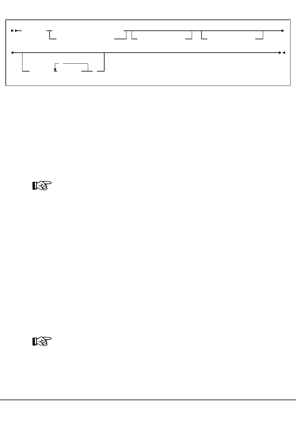
Chapter 3. HSC Control Statements and HSC Start Procedure 111
1st ed., 6/30/04 - 312579601
Syntax
Control Statement Name
LMUPDEF
Initiates the LMUPDEF command and control statement.
Parameters
DATASET or DSN
specifies the name of the data set containing the LMUPATH statements to be
processed and, optionally, an OPTion TITLE statement.
Note: The definition data set may contain VOLATTR, UNITATTR, TAPEREQ,
LMUPATH, and OPTion TITLE statements.
• Only OPTion TITLE and LMUPATH statements are processed.
• If any other statement is encountered, an error message is issued and the
statement is ignored.
dataset.name
specifies the name of the data set containing the LMUPATH address
parameters. If the data set name includes a member name, dataset.name must be
enclosed in quotes. For example,
DATASET(‘YOUR.DSN(MEMBER)’)
VOLume
specifies the serial number of the DASD volume on which the data set resides. This
parameter is optional. Specify the VOLume parameter if the data set is not cataloged,
or if a data set on a volume other than the volume indicated by the catalog is to be
used.
Note: The volume specified must be a DASD volume.
volser
specifies the volume serial number for the definition data set.
LMUPDEF
DSN(dataset.name)
DATASET(dataset.name)
VOLume(volser)UNIT(unitname)
HOSTID( host-id
,
)
LMUPDEF

112 VM/HSC 6.0 System Programmer’s Guide
1st ed., 6/30/04 - 312579601
UNIT
specifies the unit where the definition data set is located.
unitname
specifies the unit name. If the definition data set is not cataloged and this
parameter is omitted, a unit name of SYSALLDA is the default.
HOSTID
(This parameter is valid only for use in PARMLIB, so that multiple systems can
share a PARMLIB member containing TAPEREQ, VOLATTR, UNITATTR, or
LMUPATH statements for different releases of HSC. If entered from the console,
message SLS0018I is issued.)
Optionally, limits the execution of this control statement to the specified hosts. If one
of the specified hostids matches the host executing this control statement, the control
statement is executed for that host. Otherwise, it is ignored. If this parameter is
omitted, the control statement is executed on all hosts.
host-id
specifies the name of one or more hosts from which to execute this control
statement. Multiple hosts must be separated by commas.
Examples
The following examples illustrate the use of the LMUPDEF statement.
Load the LMUPATH Parameters From YOUR.DSN(MEMBER)
Load the LMUPATH Parameters From DASD Volume DISK03
LMUPDEF DSN(‘YOUR.DSN(MEMBER)’)
LMUPDEF DSN(YOUR.DSN2) VOLUME(DISK03)
LMUPDEF
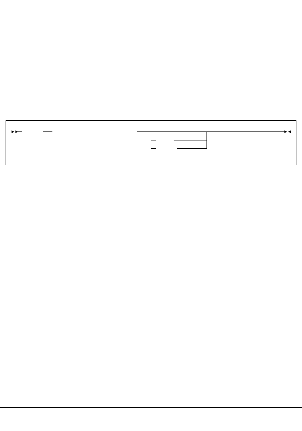
Chapter 3. HSC Control Statements and HSC Start Procedure 113
1st ed., 6/30/04 - 312579601
OPTion TITLE Control Statement
The OPTion TITLE statement is used to specify an identifying string for a definition data
set. The identifying string can be any information that helps the user describe the contents
of the definition data set.
The OPTion TITLE statement must be placed in the definition data set; it cannot be issued
as an operator command. If more than one OPTion statement is specified in the definition
data set, only the identifying string of the last OPTion statement encountered is retained.
The identifying string can be displayed with HSC Display commands. Refer to
‘‘DISPLAY Command’’ in the HSC Operator’s Guide for descriptions of command syntax
and parameters.
Syntax
Control Statement Name
OPTion
initiates the OPTion control statement.
Parameters
TITLE
specifies an identifying string for the definition data set. If this statement is omitted,
the definition data set has no identifying string associated with it.
identifying-string
specifies the identifying string. The maximum length of the identifying string is
fifty characters. If the identifying string includes one or more spaces, or any
characters
TRACE or TRACEF
used to control internal tracing of HSC table lookups. During problem resolution,
Software Support may request that you specify one of these parameters.
OPTion TITLE(identifying-string)
TRACE
TRACEF
OPTion TITLE

114 VM/HSC 6.0 System Programmer’s Guide
1st ed., 6/30/04 - 312579601
Example
The following example illustrates the use of the OPTion TITLE control statement.
Specify an Identifying String For a Definition Data Set
OPTION TITLE(‘SAMPLE IDENTIFYING STRING’)
OPTion TITLE

Chapter 3. HSC Control Statements and HSC Start Procedure 115
1st ed., 6/30/04 - 312579601
Scratch Subpool Definition (SCRPDEF) Command and Control Statement
The SCRPDEF command and control statement is used to specify the definition data set
that contains scratch subpool (SCRPOol) parameter statements. (Refer to “Scratch
Subpool Control Statement” on page 100 for details on syntax and parameters.) The data
set must be a sequential or a partitioned data set (PDS) with any valid record format
(RECFM). Also, the definition data set must contain one or more SCRPOol statements.
The SCRPDEF statement may be specified in the HSC PARMLIB, or it may be issued as
an operator command to dynamically load or reload scratch subpool parameters. (Refer to
“PARMLIB Control Statements” on page 83 for an explanation of PARMLIB.)
Warning:
1. If you reissue SCRPDEF, it resets subpool threshold values to 0. In this case, you
must reenter the subpool thresholds on the Warn command SUBpool parameter. Only
subpool thresholds are affected; ACS and LSM thresholds are not reset.
2. The SCRPDEF command does not refresh LibraryStation subpool(s) unless
LibraryStation is restarted using LS STOP and LS INIT.
If a definition file is changed by a SCRPDEF operator command, and if the change is to be
permanent, you must update PARMLIB before restarting the HSC. If the definition file is
to be modified for a given shift or application, remember that the new definition remains
in effect until another definition is loaded or the HSC is recycled. The definition file then
reverts to the PARMLIB specification. Thus, SCRPDEF can be used to temporarily
change a definition file.
Caution: If SCRPOol parameter statements are specified in PARMLIB, SCRPDEF is
disabled and dynamic scratch pool reload is not allowed.
Definition commands issued on one host are in effect only on that host. If different hosts
use the same definition data set, then the tape request parameter statements are shared by
those hosts.
Notes:
1. When the SCRPDEF command is issued, if the definition data set contains errors, an
HSC message provides the parameter in error, a description of the problem, and the
line number where the error occurred. If the definition data set contains errors, none
of the attributes specified in the SCRPOol control statement(s) will be loaded (put
into effect), which may cause data sets to be created on the wrong type of media and
incorrect devices to be allocated. Message SLS1627I is displayed if errors are
encountered. If 50 errors are encountered, the remainder of the data set is not
checked. Correct the problem and reissue the command.
2. The SCRPDEF command and control statement executes at both base and full
service levels of the HSC.
3. If you issue multiple SCRPDEF statements, the last one processed is currently active.
You can determine which SCRPDEF statement is active by entering the Display
SCRPDEF command.
SCRPDEF
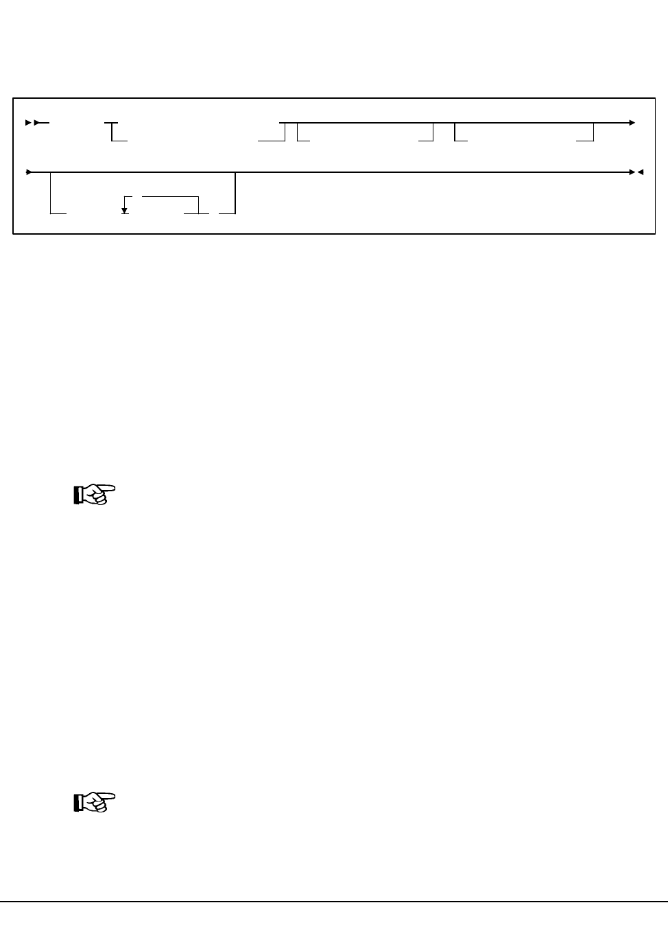
116 VM/HSC 6.0 System Programmer’s Guide
1st ed., 6/30/04 - 312579601
4. For additional information about syntax, refer to “Control Statement Syntax
Conventions” on page 439.
Syntax
Control Statement Name
SCRPDEF
initiates the SCRPDEF command and control statement.
Parameters
DATASET or DSN
specifies the name of the data set containing the SCRPOol statements to be processed
and, optionally, an OPTion TITLE statement. (Refer to “Scratch Subpool Control
Statement” on page 100 and “OPTion TITLE Control Statement” on page 113 for
details on syntax and parameters).
Note: The definition data set may contain SCRPOol, TAPEREQ, UNITATTR,
VOLATTR, and OPTion TITLE statements. Only OPTion TITLE and SCRPOol
statements are processed. If any other statement is encountered, an error message is
issued and the statement is ignored.
dataset.name
specifies the name of the data set containing scratch subpool parameters. If the
data set name includes a member name, dataset.name must be enclosed in
quotes. For example,
DATASET(‘YOUR.DSN(MEMBER)’)
VOLume
specifies the serial number of the DASD volume on which the data set resides. This
parameter is optional. Specify the VOLume parameter if the data set is not cataloged,
or if a data set on a volume other than the volume indicated by the catalog is to be
used.
Note: The volume specified must be a DASD volume.
volser
specifies the volume serial number for the definition data set.
SCRPDEF
DSN(dataset.name)
DATASET(dataset.name)
VOLume(volser)UNIT(unitname)
HOSTID( host-id
,
)
SCRPDEF

Chapter 3. HSC Control Statements and HSC Start Procedure 117
1st ed., 6/30/04 - 312579601
UNIT
specifies the unit where the definition data set is located.
unitname
specifies the unit name. If the definition data set is not cataloged and this
parameter is omitted, a unit name of SYSALLDA is the default.
HOSTID
(This parameter is valid only for use in PARMLIB, so that multiple systems can
share a PARMLIB member containing SCRPOol, TAPEREQ, VOLATTR, or
UNITATTR statements for different releases of HSC. If entered from the console,
message SLS0018I is issued.)
Optionally, the HOSTid parameter limits the execution of this control statement to
the specified hosts. If one of the specified hostids matches the host executing this
control statement, the control statement is executed for that host. Otherwise, it is
ignored. If this parameter is omitted, the control statement is executed on all hosts.
host-id
specifies the name of one or more hosts from which to execute this control
statement. Multiple hosts must be separated by commas.
Examples
The following examples illustrate the use of the SCRPDEF statement.
Load the SCRPOol Parameters From YOUR.DSN(MEMBER)
Load the SCRPOol Parameters From DASD Volume DISK01
SCRPDEF DSN(‘YOUR.DSN(MEMBER)’)
SCRPDEF DSN(‘YOUR.DSN(MEMBER)’) VOLUME(DISK01)
SCRPDEF

118 VM/HSC 6.0 System Programmer’s Guide
1st ed., 6/30/04 - 312579601
Tape Request (TAPEREQ) Control Statement
The TAPEREQ control statement is used to specify tape request attributes. TAPEREQ
statements are read from the definition data set specified by the TREQDEF command.
(Refer to “Tape Request Definition (TREQDEF) Command and Control Statement” on
page 133 for details on syntax and parameters.) The TAPEREQ statement must be placed
in the definition data set; it cannot be issued as an operator command.
To put multiple data sets on multiple volumes, a TAPEREQ statement must be coded for
each data set name.
TAPEREQ Usage
As the HSC processes each allocation request, it searches the TAPEREQ statements in the
order that they appear in the definition data set to determine the media type, recording
technique or model, and subpool parameters to assign to the request. One or more
TAPEREQ statements may match the request’s input criteria.
When there are multiple matching TAPEREQ statements containing different parameters,
the HSC merges the parameters from the matching statements. Each parameter value is
searched for independently, and for each, the first matching TAPEREQ statement is used.
For this reason, StorageTek recommends that you:
• order the TAPEREQ statements from most specific to most general
• specify all applicable parameters on all TAPEREQ statements.
Conflicting parameter assignment can result when multiple TAPEREQ statements are
found and their parameters merged. For example, assuming the subpool REDWOOD
contains only HELical (Redwood) cartridges, the following TAPEREQs produce
inconsistent parameter assignment:
These statements cause the HSC to attempt to select a Standard scratch cartridge from a
subpool that contains only helical cartridges.
To avoid such scenarios, StorageTek recommends that all applicable parameters be coded
on each TAPEREQ and that parameters such as SUBPool not be specified on generic
TAPEREQ statements. That is, MEDia and RECtech should be specified on the same
TAPEREQ statement as SUBPool.
.
.
.
TAPEREQ JOBNAME(ABC) SUBPOOL(REDWOOD)
.
.
TAPEREQ JOBNAME(**) MEDIA(S)
.
.
.
TAPEREQ

Chapter 3. HSC Control Statements and HSC Start Procedure 119
1st ed., 6/30/04 - 312579601
After searching the TAPEREQ statements, the HSC
• selects the appropriate devices
• mounts cartridges that are the right media type.
The TAPEREQ parameters are divided into selection criteria (i.e., input) parameters, and
media and recording technique or model (i.e., output or result) parameters. The selection
criteria are used to locate the first TAPEREQ statement that matches the request under
consideration. Media and recording technique (or model) provide information that is used
to modify the request. The TAPEREQ statement is in essence an IF-THEN statement: IF
the selection criteria parameters (ANDed together) match the current tape request
variables, THEN the media and recording technique parameters apply.
The HSC uses the TAPEREQ specifications during device allocation to determine which
transports to leave eligible for selection, and during mount processing to determine media
requirements.
During device allocation processing for specific requests, the HSC uses volume and
TAPEREQ information. For nonspecific (scratch) requests, the HSC uses only TAPEREQ
information. The HSC searches the TAPEREQ statements for media type and recording
technique values and uses these values to mark inappropriate transports ineligible for the
request.
If the HSC is unable to match the request with media type and recording technique values,
then media type and recording technique are set to undefined and any available transport is
eligible for allocation. This condition can occur for any of the following reasons:
• None of the TAPEREQ statements matches the request.
• There is a matching TAPEREQ statement, but it does not specify media type and
recording technique values.
• There is no TAPEREQ definition data set loaded.
During mount processing for a nonspecific request, the HSC searches the TAPEREQ
statements for a media type value. The HSC uses this value to exclude cartridges of the
wrong media type.
If the HSC is unable to match the request with a media type value, then media type is
determined as shown in Table 5 on page 126.
Disabling a TAPEREQ Definition
Use the following procedure to disable a TAPEREQ definition.
1. Edit the definition data set containing the current TAPEREQ statements.
2. Delete the parameters of the TAPEREQ statement you want to disable, or delete or
comment out the TAPEREQ statement.
3. Issue the TREQDEF command to reload the definition data set.
TAPEREQ

120 VM/HSC 6.0 System Programmer’s Guide
1st ed., 6/30/04 - 312579601
With the modified definition data set in effect, the HSC searches the remaining TAPEREQ
statements to determine the media type and recording technique (or model) to assign to a
request.
To disable all TAPEREQ definitions, load a definition data set that contains only one
TAPEREQ statement with no parameters. Refer to Table 5 on page 126 and Table 6 on
page 128 to see a list of TAPEREQ media and recording technique (or model) default
values.
TAPEREQ
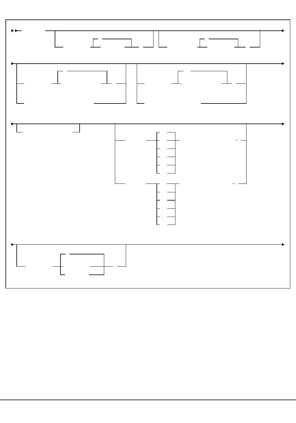
Chapter 3. HSC Control Statements and HSC Start Procedure 121
1st ed., 6/30/04 - 312579601
Syntax
TAPEREQ
JOBname( jobname )
*
STEPname( stepname )
*
PROGram(
PGMname(program-name)
*
program-name )DATASET(
DSN(dataset-name)
**
dataset-name )
EXPDT(
RETPD( ,retention-period
NE
GT
LT
LE
EQ
GE
,expiration-date
EQ
NE
GT
LT
GE
LE
)
)
VOLType(
*
Specific
Nonspec
)
DDName(DD-name)
TAPEREQ
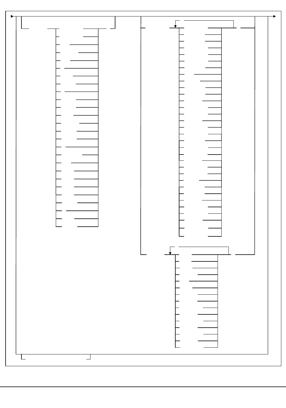
122 VM/HSC 6.0 System Programmer’s Guide
1st ed., 6/30/04 - 312579601
Syntax (continued)
MEDia( LONGItud )
R
Standard
CST
MEDIA1
STD
1
3480
ECART
E
ECCST
ETAPE
Long
MEDIA2
3490E
ZCART
Z
HELical
DD3
DD3A
DD3B
DD3C
STK1
STK1R
STK2
STK2P
RECtech( LONGItud )
18track
36track
36Atrack
36Btrack
36Ctrack
HELical
DD3
STK1R
STK1R34
STK1R35
STK1RA
STK1RA34
STK1RA35
STK1RB
STK1RB34
STK1RB35
STK1RAB
STK1RC
STK1RC34
STK1RC35
STK2P
STK2P34
STK2P35
STK2PA
STK2PB
,
STK2PA34
STK2PA35
STK2PB34
STK2PB35
STK1RAB4
STK1RAB5
MODel( 4480 )
T9840C
T9840C35
4490
9490
9490EE
SD3
9840
984035
T9840B
T9840B35
T9940A
T9940A35
T9940B
T9940B35
,
model1
SUBPool(subpool-name)
TAPEREQ

Chapter 3. HSC Control Statements and HSC Start Procedure 123
1st ed., 6/30/04 - 312579601
Control Statement Name
TAPEREQ
initiates the TAPEREQ control statement. If any of the following apply:
• there is no TAPEREQ statement specified in the definition data set to match a
request, or
• no matching TAPEREQ statement specifies MEDia or RECtech, or
• no definition data set loaded,
then MEDia and RECtech are set to undefined, which matches all requests. Any available
device is eligible for allocation.
Table 5 on page 126 shows default values used if the media type is omitted.
Parameters
The TAPEREQ selection criteria parameters are shown below. The JOBname, STEPname,
PROGram, and DATASET parameters can have values that include the following wildcard
characters:
% or ? any single non-blank character.
* any character string (length zero to 8) not to exceed one qualification level.
For example, A.B.* matches A.B and A.B.C, but does not match A.B.C.D.
** used only in DATASET. Indicates any number of qualifiers (zero or more).
Cannot be used with any other characters within a qualifier. For example,
A.B.** matches A.B, A.B.C, A.B.C.D, A.B.C.D.E, and so forth.
JOBname
optionally, identifies the job name. If JOBname is not specified, the default value is
*.
job-name
specifies the job name. The TAPEREQ statement is used only when the
specified job-name matches the job name in the request.
STEPname
optionally, specifies the step name. If the STEPname parameter is not specified, the
default value is *.
step-name
specifies the step name. This parameter cannot be more than eight characters
long, and periods are not allowed within step-name. The TAPEREQ statement
is used only when the specified step-name matches the step name in the request.
TAPEREQ

124 VM/HSC 6.0 System Programmer’s Guide
1st ed., 6/30/04 - 312579601
PROGram or PGMname
optionally, specifies the program name. If PROGram is not specified, the default
value is *. The program name used is the job step program name.
program-name
specifies the program name.The TAPEREQ statement is used only when the
specified program-name matches the program name in the request.
DATASET or DSN
optionally, specifies the data set name. If DATASET (or DSN) is not specified, the
default value is **. The rules of SMS and RACF generics are followed for this
parameter.
Note: The name you specify for this parameter may be different from the value
coded in the DSN parameter on a DD statement. For example,
DSN=&&ABC
may be coded on a DD statement if a data set is temporary. However, the actual
data set name is not &&ABC. Similarly, if the DSN parameter refers back to a
previous DD statement, the data set name is resolved to the referred to data set.
Thus, the data set referred to must be coded on the DATASET parameter in
order for the TAPEREQ control statement to be processed.
dataset.name
specifies the data set name. The TAPEREQ statement is used only when the
specified dataset.name matches the data set name in the request.
DDName
optionally, specifies the DDname. If DDName is not specified, the default value is *.
DD-name
specifies the DDname. The TAPEREQ statement is used only when the
specified DD-name matches the DDname in the request.
RETPD
optionally, specifies the retention period and the relationship that must exist. If you
do not specify either RETPD or EXPDT, the default value is RETPD(GE,0) (any
expiration date will match this criterion).
EQ equal to
NE not equal to
GT greater than
GE greater than or equal to
LT less than
LE less than or equal to.
TAPEREQ

Chapter 3. HSC Control Statements and HSC Start Procedure 125
1st ed., 6/30/04 - 312579601
retention-period
specifies the retention period in days for the data set. Specify the number of
days as a 1- to 4-digit decimal number.
EXPDT
optionally, specifies the expiration date and the relationship that must exist.
expiration-date
specifies the expiration date of the data set in yyddd or yyyy/ddd format.
VOLType
optionally, indicates whether or not a nonspecific volume was requested. If
VOLType is omitted, the default value is * (either scratch or specific will match).
Specific
specifies that a specific volume was requested. The TAPEREQ statement is
used only for a scratch request where a specific volume is specified.
Note: TAPEREQ never overrides the actual media type of the specified volume
if it is taken from the media label or VOLATTR.
Nonspec
specifies that a nonspecific (scratch) volume was requested. The TAPEREQ
statement is matched, only no VOLSER is specified (a scratch request).
The TAPEREQ media and recording technique parameters are as follows:
MEDia
optionally, specifies the type of media for a data set being created. You can enter a
list of media types, but they must be separated by commas.
Notes:
1. A list specifies a generic pool from which a selection is made. There is no
implied priority.
2. The SL8500 library supports only the T9x40 (9840/T9840B/T9840C and
T9940A/T9940B) media types and recording techniques.
EQ equal to
NE not equal to
GT greater than
GE greater than or equal to
LT less than
LE less than or equal to.
TAPEREQ

126 VM/HSC 6.0 System Programmer’s Guide
1st ed., 6/30/04 - 312579601
This parameter is ignored for an existing data set if the media characteristics are
determined by the volume.
If this parameter is not specified, a default is chosen based on the value of the
RECtech parameter. Table 5 shows default values used if MEDia is omitted.
To avoid problems, StorageTek recommends that all TAPEREQ statements specify
MEDia and RECtech consistently. Make sure to include either one or both parameters on
each statement. If both media type and recording technique are omitted, all available
devices are eligible for allocation.
Valid media types are:
LONGItud
indicates any Standard, ECART, or ZCART cartridge.
Standard
indicates a standard length, 3480 cartridge. It can be read on any longitudinal
drives (4480, 4490, 9490, or 9490EE). Data can be written in 36-track mode on
4490, 9490, or 9490EE transports but cannot be read on an 18-track (4480)
drive. Synonyms for this type of cartridge include:
• CST
•MEDIA1
• STD
•1
• 3480.
ECART
indicates a 3490E, extended capacity cartridge. It can be used only on a
36-track drive (4490, 9490, or 9490EE). Synonyms include:
Table 5. TAPEREQ MEDia Default Values
RECtech Entered: MEDia Default:
18track Standard
36track, 36Atrack, 36Btrack LONGItud
36Ctrack ZCART
LONGItud LONGItud
DD3, HELical DD3
STK1R, STK1R34, STK1R35,
STK1RA, STK1RA34, STK1RA35,
STK1RB, STK1RB34, STK1RB35,
STK1RAB, STK1RAB4, STK1RAB5,
STK1RC, STK1RC34, STK1RC35
STK1R
STK2P, STK2P34, STK2P35, STK2PA,
STK2PA34, STK2PA35, STK2PB,
STK2PB34, STK2PB35
STK2P
TAPEREQ
Chapter 3. HSC Control Statements and HSC Start Procedure 127
1st ed., 6/30/04 - 312579601
•E
• ECCST
• ETAPE
•Long
•MEDIA2
• 3490E.
ZCART
indicates a 3490E, extended capacity cartridge that provides greater storage
capacity than an ECART. It can be used only on a 9490EE drive.
ZCART can be abbreviated as Z.
DD3
indicates any DD3A, DD3B, or DD3C (HELical) cartridge.
DD3A, DD3B, DD3C
indicates a helical cartridge. The media indicator in the external label is
encoded with the cartridge type (A, B, or C).
Note: DD3A, DD3B, or DD3C can be abbreviated to A, B, or C, respectively.
Types of helical cartridges, along with their associated media capacities, are:
•A - 10GB
•B - 25GB
•C - 50GB.
Data capacity differences between DD3A, DD3B, and DD3C cartridges are
related to the length of the tape in the cartridge, not to the recording density of
the data.
STK1
indicates any T9840 cartridge.
STK1R
indicates a T9840, 20GB data cartridge. The media indicator in the external
label is encoded with the cartridge type (R).
Note: STK1R can be abbreviated to R.
STK2
indicates any T9940 cartridge. This parameter is the default for all T9940A and
T9940B data cartridge types.
STK2P
indicates a T9940 data cartridge. The media indicator in the external label is
encoded with the cartridge type (P).
Note: STK2P can be abbreviated to P.
T9940 cartridge media capacities are 60GB (T9940A) or 200GB (T9940B).
TAPEREQ

128 VM/HSC 6.0 System Programmer’s Guide
1st ed., 6/30/04 - 312579601
RECtech
optionally, specifies the method used to record data tracks on the tape surface for the
desired data set. You can enter a list of recording techniques, but they must be
separated by commas.
Notes:
1. A list specifies a generic pool from which a selection is made. There is no
implied priority.
2. The SL8500 library supports only the T9x40 (9840/T9840B/T9840C and
T9940A/T9940B) media types and recording techniques.
RECtech and MODel are mutually exclusive.
If this parameter is not specified on any matching TAPEREQ, a default is chosen
based on the value of the MEDia parameter on the first matching TAPEREQ. Table 6
shows default values used if RECtech is omitted.
To avoid problems, StorageTek recommends that all TAPEREQ statements specify
MEDia and RECtech consistently. Make sure to include either one or both parameters on
each statement.
If both media type and recording technique are omitted, all available devices are eligible
for allocation.
Valid recording techniques are:
LONGItud
indicates any device that uses longitudinal recording.
18track
indicates a 4480 transport.
36track
indicates a 4490, 9490, or 9490EE transport (any device that records in 36-track
mode).
Table 6. TAPEREQ RECtech Default Values
MEDia Entered: RECtech Default:
LONGItud LONGItud
Standard LONGItud
ECART 36track
ZCART 36Ctrack
DD3, DD3A, DD3B, DD3C DD3
STK1, STK1R STK1R
STK2, STK2P STK2P
TAPEREQ

Chapter 3. HSC Control Statements and HSC Start Procedure 129
1st ed., 6/30/04 - 312579601
36Atrack
indicates a 4490 transport.
36Btrack
indicates a 9490 transport.
36Ctrack
indicates a 9490EE transport.
HELical
indicates a device using helical recording.
DD3
indicates a device using helical recording.
STK1R
indicates any 9840 or T9840B transport.
STK1R34
indicates a 3490E-image 9840 or T9840B transport.
STK1R35
indicates a 3590-image 9840 or T9840B transport.
STK1RA
indicates a 3490E or 3590-image 9840 transport.
STK1RA34
indicates a 3490E-image 9840 transport.
STK1RA35
indicates a 3590-image 9840 transport.
STK1RB
indicates a 3490E or 3590-image T9840B transport.
STK1RB34
indicates a 3490E-image T9840B transport.
STK1RB35
indicates a 3590-image T9840B transport.
STK1RAB
indicates a 3490E or 3590-image T9840A or T9840B transport.
STK1RAB4
indicates a 3490E-image T9840A or T9840B transport.
STK1RAB5
indicates a 3590E-image T9840A or T9840B transport.
TAPEREQ

130 VM/HSC 6.0 System Programmer’s Guide
1st ed., 6/30/04 - 312579601
STK1RC
indicates a 3490E or 3590-image T9840C transport.
STK1RC34
indicates a 3490-image T9840C transport.
STK1RC35
indicates a 3590-image T9840C transport.
STK2P
indicates any T9940A transport.
STK2P34
indicates a 3490E-image T9940A transport.
STK2P35
indicates a 3590-image T9940A transport.
STK2PA
indicates a T9940A transport.
STK2PA34
indicates a 3490E-image T9940A transport.
STK2PA35
indicates a 3590-image T9940A transport.
STK2PB
indicates a T9940B transport.
STK2PB34
indicates a 3490E-image T9940B transport.
STK2PB35
indicates a 3590-image T9940B transport.
MODel
optionally, specifies the model number of a transport. You can enter a list of models,
but they must be separated by commas.
Note: A list specifies a generic pool from which a selection is made. There is no
implied priority.
MODel provides the same type of information as RECtech, but a user may find it
more convenient to specify a transport model than a recording technique.
MODel and RECtech are mutually exclusive.
4480
indicates a 4480 (18-track) transport.
TAPEREQ

Chapter 3. HSC Control Statements and HSC Start Procedure 131
1st ed., 6/30/04 - 312579601
4490
indicates a 4490 (36-track Silverton) transport.
9490
indicates a 9490 (36-track Timberline) transport.
9490EE
indicates a 9490EE (36-track Timberline EE) transport.
SD3
indicates an SD-3 (RedWood) transport.
9840
indicates a 3490E-image 9840 transport.
984035
indicates a 3590-image 9840 transport.
T9840B
indicates a 3490E-image T9840B transport.
T9840B35
indicates a 3590-image T9840B transport.
T9840C
indicates a 3490E-image T9840C transport.
T9840C35
indicates a 3590-image T9840C transport.
T9940A
indicates a 3490E-image T9940A transport.
T9940A35
indicates a 3590-image T9940A transport.
T9940B
indicates a 3490E-image T9940B transport.
T9940B35
indicates a 3590-image T9940B transport.
SUBPool
optionally, specifies the subpool used to satisfy a scratch request.
subpool-name
specifies the subpool name.
Note: Refer to “TAPEREQ Usage” on page 118 for information about avoiding
assignment of inconsistent parameters when using SUBPool.
TAPEREQ

132 VM/HSC 6.0 System Programmer’s Guide
1st ed., 6/30/04 - 312579601
Example
The following example illustrates how to use TAPEREQ statements to specify tape
request attributes.
Set Tape Request Attributes
Note: In the example above, the last TAPEREQ statement specifies a user-defined default
for all data sets that do not match one of the first three statements.
TAPEREQ DSN(BACKUP.**) MEDIA(ECART) RECTECH(36TRACK)
TAPEREQ DSN(PAYROLL.**) MED(DD3A) RECTECH(DD3)
TAPEREQ MED(STANDARD) RECTECH(36TRACK)
TAPEREQ MED(STK1R) RECTECH(STK1)
TAPEREQ

Chapter 3. HSC Control Statements and HSC Start Procedure 133
1st ed., 6/30/04 - 312579601
Tape Request Definition (TREQDEF) Command and Control Statement
The TREQDEF command and control statement is used to specify the definition data set
that contains tape request (TAPEREQ) parameter statements. (Refer to “Tape Request
(TAPEREQ) Control Statement” on page 118 for details on syntax and parameters.) The
data set must be a sequential or a partitioned data set (PDS) with any valid record format
(RECFM). Also, the definition data set must contain one or more TAPEREQ statements.
The TREQDEF statement may be specified in the HSC PARMLIB, or it may be issued as
an operator command to dynamically load or reload tape request parameters. (Refer to
“PARMLIB Control Statements” on page 83 for an explanation of PARMLIB.) If a
definition file is changed by a TREQDEF operator command, and if the change is to be
permanent, you must update PARMLIB before restarting the HSC.
If the definition file is to be modified for a given shift or application, remember that the
new definition remains in effect until another definition is loaded or the HSC is recycled.
The definition file then reverts to the PARMLIB specification. Thus, TREQDEF can be
used to temporarily change a definition file.
Definition commands issued on one host are in effect only on that host. If different hosts
use the same definition data set, then the tape request parameter statements are shared by
those hosts.
Notes:
1. When the TREQDEF command is issued, if the definition data set contains errors, an
HSC message provides the parameter in error, a description of the problem, and the
line number where the error occurred. If the definition data set contains errors, none
of the attributes specified in the TAPEREQ control statement(s) will be loaded (put
into effect), which may cause data sets to be created on the wrong type of media and
incorrect devices to be allocated. Message SLS1627I is displayed if errors are
encountered. If 50 errors are encountered, the remainder of the data set is not
checked. Correct the problem and reissue the command.
2. The TREQDEF command and control statement executes at both base and full
service levels of the HSC.
3. If you issue multiple TREQDEF statements, the last one processed is currently
active. You can determine which TREQDEF statement is active by entering the
Display TREQDEF command.
TREQDEF
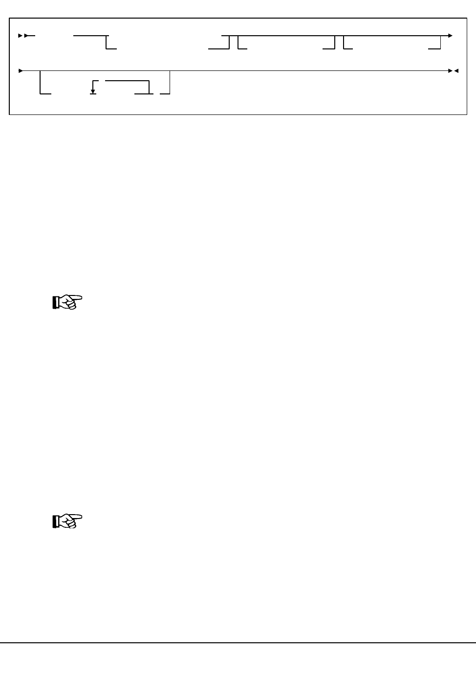
134 VM/HSC 6.0 System Programmer’s Guide
1st ed., 6/30/04 - 312579601
Syntax
Control Statement Name
TREQDEF
initiates the TREQDEF command and control statement
Parameters
DATASET or DSN
specifies the name of the data set containing the TAPEREQ statements to be
processed and, optionally, an OPTion TITLE statement. (Refer to “Tape Request
(TAPEREQ) Control Statement” on page 118 and “OPTion TITLE Control
Statement” on page 113 for details on syntax and parameters).
Note: The definition data set may contain TAPEREQ, UNITATTR, VOLATTR, and
OPTion TITLE statements. Only OPTion TITLE and TAPEREQ statements are
processed. If any other statement is encountered, an error message is issued and the
statement is ignored.
dataset.name
specifies the name of the data set containing tape request parameters. If the data
set name includes a member name, dataset.name must be enclosed in quotes.
For example,
DATASET(‘YOUR.DSN(MEMBER)’)
VOLume
specifies the serial number of the DASD volume on which the data set resides. This
parameter is optional. Specify the VOLume parameter if the data set is not cataloged,
or if a data set on a volume other than the volume indicated by the catalog is to be
used.
Note: The volume specified must be a DASD volume.
volser
specifies the volume serial number for the definition data set.
TREQDEF DATASET(dataset.name)
DSN(dataset.name)VOLume(volser)UNIT(unitname)
HOSTID( host-id
,
)
TREQDEF

Chapter 3. HSC Control Statements and HSC Start Procedure 135
1st ed., 6/30/04 - 312579601
UNIT
specifies the unit where the definition data set is located.
unitname
specifies the unit name. If the definition data set is not cataloged and this
parameter is omitted, a unit name of SYSALLDA is the default.
HOSTID
(This parameter is valid only for use in PARMLIB, so that multiple systems can
share a PARMLIB member containing TAPEREQ, VOLATTR, or UNITATTR
statements for different releases of HSC. If entered from the console, message
SLS0018I is issued.)
Optionally, the HOSTid parameter limits the execution of this control statement to
the specified hosts. If one of the specified hostids matches the host executing this
control statement, the control statement is executed for that host. Otherwise, it is
ignored. If this parameter is omitted, the control statement is executed on all hosts.
host-id
specifies the name of one or more hosts from which to execute this control
statement. Multiple hosts must be separated by commas.
Examples
The following examples illustrate the use of the TREQDEF statement.
Load the TAPEREQ Parameters From YOUR.DSN(MEMBER)
Load the TAPEREQ Parameters From DASD Volume DISK01
TREQDEF DSN(‘YOUR.DSN(MEMBER)’)
TREQDEF DSN(YOUR.DSN1) VOLUME(DISK01)
TREQDEF

136 VM/HSC 6.0 System Programmer’s Guide
1st ed., 6/30/04 - 312579601
Unit Attribute (UNITATTR) Control Statement
The UNITATTR statement specifies unit attributes and allows the user to define the model
number of transports. A series of UNITATTR statements can be specified and are
contained in the definition data set named in the UNITDEF statement. The first statement
that matches the requested attributes is used. (Refer to “Unit Attribute Definition
(UNITDEF) Command and Control Statement” on page 140 for details on syntax and
parameters.) The UNITATTR statement must be placed in the definition data set; it cannot
be issued as an operator command.
UNITATTR Usage
UNITATTRs are used to distinguish between devices that are configured as either 3490E
or 3590 device types:
• 3490E-type
- 4490
- 9490
- 9490EE
-SD-3
- 9840
- T9840B
- T9840C
- T9940A
- T9940B.
• 3590-type
-SD-3
- 9840
- T9840B
- T9840C
- T9940A
- T9940B.
Note: SD-3s, 9840s, T9840Bs, T9840Cs, T9940As, and T9940Bs can be defined as
either 3490E or 3590. 3490E-type transports not defined by UNITATTRs are
presumed to be 4490 transports; 3590-type transports are presumed to be 9840
transports.
To allow the HSC to operate correctly, the user must specify UNITATTR statements for all
nonlibrary transport models that appear to the operating system as 3490E-type and
3590-type devices. For library devices, the model type is determined by the LMU. For
newly defined drives, if the LSM has not been online, the model has not been reported by
the LMU. Because of this, StorageTek recommends that UNITATTRs be defined for both
library and nonlibrary devices.
Note: If you change your transport configuration, you may need to edit the definition
data set containing the UNITATTR statements and reload it by issuing the UNITDEF
command.
UNITATTR
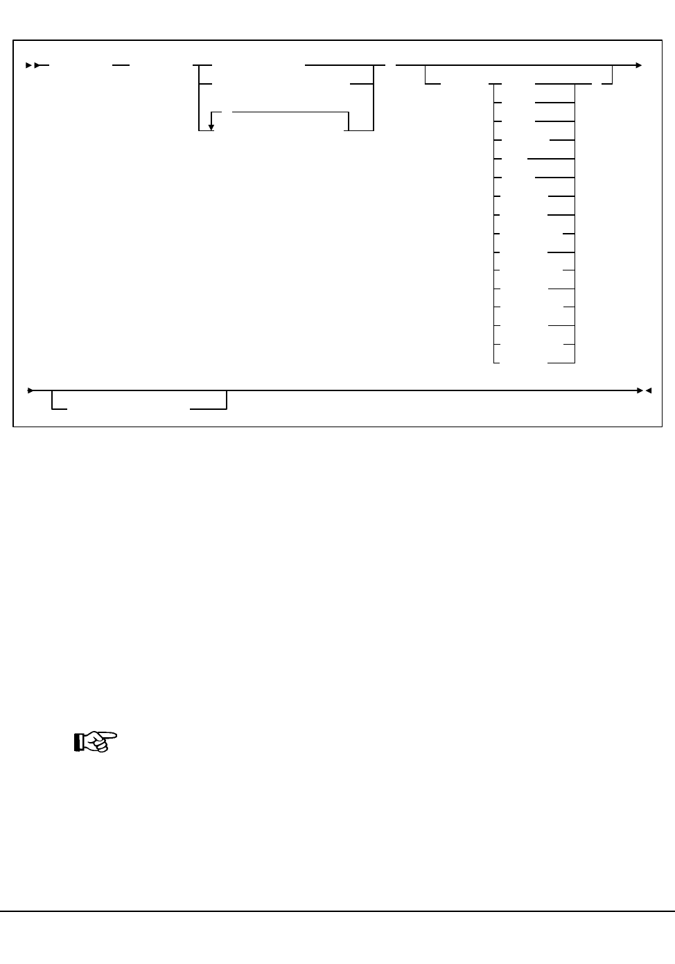
Chapter 3. HSC Control Statements and HSC Start Procedure 137
1st ed., 6/30/04 - 312579601
Syntax
Control Statement Name
UNITATTR
initiates the UNITATTR control statement.
Parameters
ADDRess
specifies the unit address to which this definition applies.
unit-address
indicates a single unit address, multiple addresses, a range of addresses, or
multiple ranges of addresses. A unit address can be specified by more than one
UNITATTR statement. In this case, the first UNITATTR statement specified
for a unit is used.
Note: The HSC does not allow duplicate or overlapping ranges of addresses to be
processed. If duplicates are encountered, the HSC issues an error message and does
not load any UNITATTRs.
UNITATTR ADDRess( )
MODel( 4480
4490
9490
9490EE
SD3
9840
)
unit-address
unit-address-list
unit-address-range
,
984035
T9940A
NETHOST(host-id)
T9940A35
T9940B
T9840B
T9840B35
IGNORE
UNITATTR ADDRess( )
MODel( 4480
4490
9490
9490EE
SD3
9840
)
unit-address
unit-address-list
unit-address-range
,
984035
NETHOST(host-id)
T9840B
T9840B35
IGNORE
T9940B35
T9940B
T9940A35
T9940A
T9840C35
T9840C
UNITATTR

138 VM/HSC 6.0 System Programmer’s Guide
1st ed., 6/30/04 - 312579601
MODel
optionally, specifies the model number of a tape transport.
Notes:
1. If the model specified does not match that reported by the LMU, an error results
which causes all UNITATTRs to be rejected.
2. The SL8500 library supports only the T9x40 (9840/T9840B/T9840C and
T9940A/T9940B) model types.
4480
indicates a 4480 (18-track) tape transport.
4490
indicates a 4490 (36-track Silverton) tape transport.
9490
indicates a 9490 (36-track Timberline) tape transport.
9490EE
indicates a 9490EE (36-track Timberline EE) transport.
SD3
indicates an SD-3 (RedWood) tape transport.
9840
indicates a 3490E-image 9840 transport.
984035
indicates a 3590-image 9840 transport.
T9840B
indicates a 3490E-image T9840B transport.
T9840B35
indicates a 3590-image T9840B transport.
T9840C
indicates a 3490E-image T9840C transport.
T9840C35
indicates a 3590-image T9840C transport.
T9940A
indicates a 3490E-image T9940A transport.
T9940A35
indicates a 3590-image T9940A transport.
T9940B
indicates a 3490E-image T9940B transport.
UNITATTR
Chapter 3. HSC Control Statements and HSC Start Procedure 139
1st ed., 6/30/04 - 312579601
T9940B35
indicates a 3590-image T9940B transport.
IGNORE
indicates a nonexistent physical transport.
Note: IGNORE cannot be specified for a device that actually exists inside the
library. HSC validates that UNITATTR models, if specified, match those
reported by the LMU. If they do not, all UNITATTRs are rejected.
NETHOST
optionally, indicates a parameter used by LibraryStation. If this parameter is
specified, the HSC ignores the entire UNITATTR statement. Conversely,
LibraryStation ignores the statement unless NETHOST is specified.
Examples
The following example illustrates the use of the UNITATTR control statement.
Specify Unit Attribute Statements
UNITATTR ADDRESS(A90-A9F) MODEL(9490)
UNITATTR ADDR(B90,B92,B94) MOD(SD3)
UNITATTR

140 VM/HSC 6.0 System Programmer’s Guide
1st ed., 6/30/04 - 312579601
Unit Attribute Definition (UNITDEF) Command and Control Statement
The UNITDEF command and control statement allows the user to specify the data set that
contains the unit attribute (UNITATTR) statements.
The UNITDEF statement can be specified in PARMLIB, or it can be issued as an operator
command to dynamically load or reload unit attribute parameters. (Refer to ‘‘PARMLIB
Control Statements’’ in the HSC Installation Guide for an explanation of PARMLIB.) The
definitions are only in effect for the host where UNITDEF is issued.
Caution: UNITATTR statements may not load after you physically update or change
devices (for example, from a T9840A to a T9840C).If a UNITDEF control statement
is loaded before the HSC reaches the base service level, the model type stored in the
CDS may not match the UNITATTR, causing an error to be generated.
SLS1628I UNITDEF: Record 1 ...
MODEL is incompatible with UNIT
In this case, you need to reload the UNITDEF. Refer to “Swapping Library
Transports - New Model Types” on page 57 to see a procedure to remedy the
mismatch.
If a definition file is changed by a UNITDEF operator command, and if the change is to be
permanent, you must update PARMLIB before restarting the HSC. If the definition file is
to be modified for a given shift or application, remember that the new definition remains
in effect until another definition is loaded or the HSC is recycled. The definition file then
reverts to the PARMLIB specification. Thus, UNITDEF can be used to temporarily
change a definition file.
Notes:
1. When the UNITDEF command is issued, if the definition data set contains errors, an
HSC message provides the parameter in error, a description of the problem, and the
line number where the error occurred. If the definition data set contains errors, none
of the attributes specified in the UNITATTR control statement(s) will be loaded (put
into effect), which may cause the wrong transport to be allocated for a volume.
Message SLS1627I is displayed if errors are encountered. If 50 errors are
encountered, the remainder of the data set is not checked. Correct the problem and
reissue the command.
2. If you issue multiple UNITDEF statements, the last one processed is currently active.
You can determine which UNITDEF statement is active by entering the Display
UNITDEF command.
UNITDEF
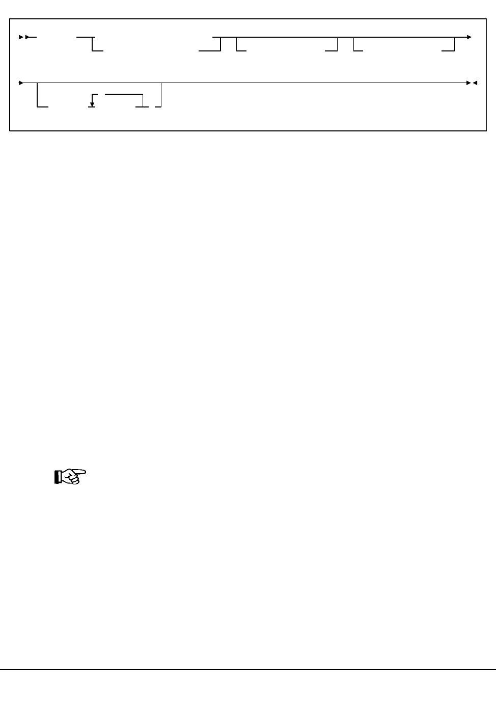
Chapter 3. HSC Control Statements and HSC Start Procedure 141
1st ed., 6/30/04 - 312579601
Syntax
Control Statement Name
UNITDEF
initiates the UNITDEF control statement.
Parameters
DATASET or DSN
specifies the name of the data set containing the UNITATTR statements to be
processed and, optionally, an OPTion TITLE statement. (Refer to “Unit Attribute
(UNITATTR) Control Statement” on page 136 and “OPTion TITLE Control
Statement” on page 113 for details on syntax and parameters.) The data set may
contain other statements, but they will be ignored.
dataset.name
specifies the name of the data set containing UNITATTR parameters. If the
dataset.name includes a member name, the entire dataset.name must be
enclosed in single quotes. For example,
DATASET(‘YOUR.DSN(MEMBER)’)
VOLume
optionally, specifies the serial number of the volume where the data set resides. If
this parameter is omitted, the data set must be cataloged.
Note: The volume must be a DASD volume.
volser
specifies the volume serial number for the definition data set.
UNIT
specifies the unit where the definition data set is located.
unitname
specifies the unit name. If the definition data set is not cataloged and this
parameter is omitted, a unit name of SYSALLDA is the default.
UNITDEF DATASET(dataset.name)
DSN(dataset.name)VOLume(volser)UNIT(unitname)
HOSTID( host-id
,
)
UNITDEF

142 VM/HSC 6.0 System Programmer’s Guide
1st ed., 6/30/04 - 312579601
HOSTID
(This parameter is valid only for use in PARMLIB, so that multiple systems can
share a PARMLIB member containing TAPEREQ, VOLATTR, or UNITATTR
statements for different releases of HSC. If entered from the console, message
SLS0018I is issued.)
Optionally, limits the execution of this control statement to the specified hosts. If one
of the specified hostids matches the host executing this control statement, the control
statement is executed for that host. Otherwise, it is ignored. If this parameter is
omitted, the control statement is executed on all hosts.
host-id
specifies the name of one or more hosts from which to execute this control
statement. Multiple hosts must be separated by commas.
Examples
The following example illustrates the use of the UNITDEF command and control
statement.
Specify a Data Set Containing UNITATTR Statements
UNITDEF DSN(‘HSC.DEF(UNITDEF)’)
UNITDEF DATASET(‘HSC.PARMLIB(MVSUNITS)’) VOLUME(MVSA01)
UNITDEF DATASET(SYSB.UNITDEFS) UNIT(A90)
UNITDEF

Chapter 3. HSC Control Statements and HSC Start Procedure 143
1st ed., 6/30/04 - 312579601
Volume Attribute (VOLATTR) Control Statement
The VOLATTR control statement is used to specify tape volume attributes. VOLATTR
statements are read from the definition data set specified by the VOLDEF command.
(Refer to “Volume Attribute Definition (VOLDEF) Command and Control Statement” on
page 154 for details on syntax and parameters.) The VOLATTR statement must be placed
in the definition data set; it cannot be issued as an operator command.
Notes:
1. You must enter a VOLATTR statement for each media type so that the HSC can
correctly determine scratch counts and preferencing for scratch allocation. It is
important that all VOLATTR control statements be accurate if you rely on
precise scratch counts.
2. A VOLATTR must exist for ECARTs that do not have a media label so that the HSC
can distinguish ECARTs from standard cartridges.
VOLATTR Usage
When the HSC needs to determine the attributes for a volume, it searches the VOLATTR
statements in the order that they appear in the definition data set. The first statement that
matches the requested volume is used to determine the attributes that are specified on that
VOLATTR statement. The search continues for any attributes that are not specified on the
first matching VOLATTR statement. These attributes are supplied by the next matching
VOLATTR that specifies the attribute(s).
For example, if MEDia is provided but RECtech is not, RECtech takes a default value
based upon the MEDia parameter. The same situation occurs if a RECtech value is present
but MEDia is not. Thus, StorageTek recommends that users:
• order the VOLATTR statements from most specific to most general
• specify only MEDia on all VOLATTR statements and let RECtech default, or
specify both MEDia and RECtech on all VOLATTR statements.
The HSC always selects a RECtech compatible with the volume’s media type; it is not
necessary to specify RECtech on VOLATTR statements unless a specific RECtech is
desired.
If RECtech is specified for any default VOLATTRs, however, it should be specified for all
VOLATTRs to avoid obtaining MEDia from one VOLATTR and RECtech from another.
Note: Run the Volume Report utility using the NONMEDEQ option to verify that
your VOLATTRs are in agreement with the CDS volume attribute record (VAR). The
VAR reflects volume information from the LMU and can be compared to the
VOLATTRs.
StorageTek recommends that the volume attribute statements in effect be the same on all
processors; if not, results are unpredictable.
VOLATTR

144 VM/HSC 6.0 System Programmer’s Guide
1st ed., 6/30/04 - 312579601
If you enter any VOLATTR statement that globally defaults to all volumes (i.e.,
VOLATTR SER(*) REC(18)), you must precede this statement with VOLATTRs
specifying the cleaning cartridges for each type of transport defined in the ACS. Cleaning
cartridges for longitudinal drives should be defined as MED(S); for helical drives,
MED(DD3D); for 9840 drives, MED(STK1U).
If global defaults are used to specify RECtech for large ranges of volumes, specify both
MEDia and RECtech on all preceding VOLATTR statements. Otherwise, for a given
VOLSER, the MEDia may be obtained from an earlier statement.
In the following example, the media type obtained from an earlier statement results in a
default RECtech of STK1R. Then, the global statement that follows specifies a global
RECtech of 36track, which is incompatible with the earlier statement.
VOLATTR SERIAL(EAG000-EAG999) MEDIA(STK1R)
VOLATTR SERIAL(*) RECTECH(36TRACK)
Disabling a VOLATTR Definition
Use the following procedure to disable a VOLATTR definition.
1. Edit the definition data set containing the current VOLATTR statements.
2. Delete the parameters of the VOLATTR statement you want to disable, or delete or
comment out the VOLATTR statement.
3. Issue the VOLDEF command to reload the definition data set.
With the modified definition data set in effect, the HSC searches the remaining
VOLATTR statements to determine the media type and recording technique for a volume.
To disable all VOLATTR definitions, load a definition data set that contains only the
statement VOLATTR SERIAL(*). Refer to Table 7 on page 148 and Table 8 on page 150
to see a list of VOLATTR media and recording technique default values.
VOLATTR
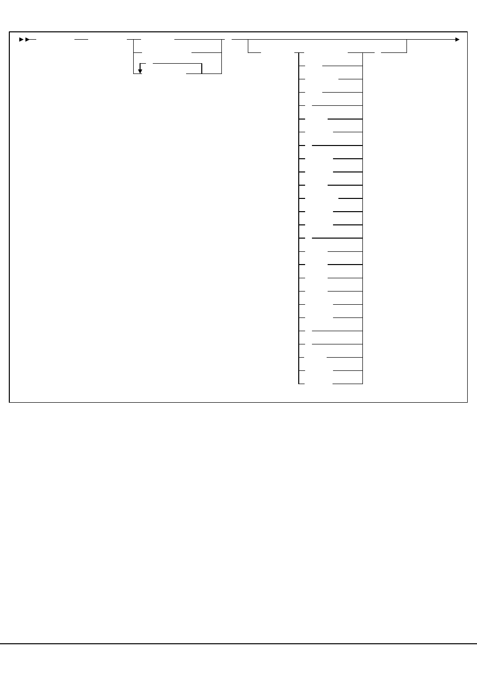
Chapter 3. HSC Control Statements and HSC Start Procedure 145
1st ed., 6/30/04 - 312579601
Syntax
This syntax diagram is continued on the next page.
VOLATTR SERial( volser
vol-range
vol-list
,
)
MEDia( Standard
CST
MEDIA1
STD
1
3480
ECART
E
ECCST
ETAPE
Long
MEDIA2
3490E
ZCART
Z
DD3A
DD3B
DD3C
DD3D
STK1R
STK1U
R
U
)
STK2
STK2P
STK2W
VOLATTR
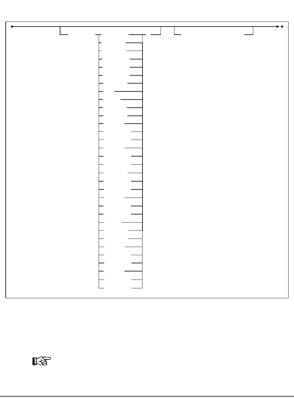
146 VM/HSC 6.0 System Programmer’s Guide
1st ed., 6/30/04 - 312579601
Syntax (continued)
Control Statement Name
VOLATTR
initiates the VOLATTR control statement. This statement applies to all cartridges
including all types of cleaning cartridges.
Note: Standard cleaning cartridges that do not match the cleaning prefix established
in the LIBGEN may be treated as scratch cartridges.
RECtech( )MAXclean(use-limit)LONGItud
18track
36track
36Atrack
36Btrack
36Ctrack
HELical
DD3
STK1R
STK1R34
STK1R35
STK1RA
STK1RA34
STK1RA35
STK2PA
STK1RAB
STK1RAB4
STK1RAB5
STK1RC
STK1RC34
STK1RC35
STK1RB
STK1RB34
STK1RB35
STK2P
STK2P34
STK2P35
STK2PB
STK2PA34
STK2PA35
STK2PB34
STK2PB35
VOLATTR

Chapter 3. HSC Control Statements and HSC Start Procedure 147
1st ed., 6/30/04 - 312579601
Parameters
SERial
specifies one or more volume serial numbers (VOLSERs) to which this definition
applies.
volser or vol-range or vol-list
identifies a single VOLSER, a VOLSER range, or a list of VOLSERs and/or
VOLSER ranges in any combination. This parameter may include the following
wildcard characters:
% or ? any single non-blank character.
* any character string (length 0 to 6).
The wildcard characters shown above may not be used in a range.
Notes:
1. On a single VOLATTR statement, all volumes specified in a list or range
must be the same media type (e.g., a Standard cartridge cannot be included
in a range of VOLSERs that also contains an ECART or DD3A cartridge).
2. If a given VOLSER is not included in any VOLATTR statement, the
MEDia value defaults to Standard; thus, RECtech defaults to LONGitud.
MEDia
optionally, specifies the type of media (cartridge) for the VOLSER designated in the
SERial parameter.
Note: The SL8500 library supports only the T9x40 (9840/T9840B/T9840C
and T9940A/T9940B) media types.
Only specific media types can be entered. Generic media types, that is, LONGItud
and HELical, cannot be specified. Refer to the syntax for this control statement to see
the parameters available to you.
VOLATTR

148 VM/HSC 6.0 System Programmer’s Guide
1st ed., 6/30/04 - 312579601
If this parameter is not specified, a default is chosen based on the value of the
RECtech parameter. Table 7 shows default values used if MEDia is omitted.
If both media type and recording technique are omitted, all media types and
recording techniques are assumed to be eligible StorageTek recommends that
MEDia always be specified on all VOLATTR statements.
Valid media types are:
Standard
indicates a standard length, 3480 cartridge. It can be read on any longitudinal
drives (4480, 4490, 9490, or 9490EE). Data can be written in 36-track mode on
4490, 9490, or 9490EE transports but cannot be read on an 18-track (4480)
drive. Synonyms for this type of cartridge include:
• CST
•MEDIA1
• STD
•1
• 3480
ECART
indicates a 3490E, extended capacity cartridge. It can be used only on a
36-track drive (4490, 9490, 9490EE). Synonyms include:
•E
• ECCST
• ETAPE
• Long
Table 7. VOLATTR MEDia Default Values
RECtech Entered: MEDia Default:
18track Standard
36track, 36Atrack, 36Btrack Standard
36Ctrack ZCART
LONGItud Standard
DD3, HELical DD3A
STK1R, STK1R34, STK1R35,
STK1RA, STK1RA34, STK1R35,
STK1RB, STK1RB34, STK1RB35,
STK1RAB, STK1RAB4, STK1RAB5,
STK1RC, STK1RC34, STK1RC35
STK1R
STK2P, STK2P34, STK2P35, STK2PA,
STK2PA34, STK2PA35, STK2PB,
STK2PB34, STK2PB35
STK2P
VOLATTR

Chapter 3. HSC Control Statements and HSC Start Procedure 149
1st ed., 6/30/04 - 312579601
•MEDIA2
• 3490E
ZCART
indicates a 3490E, extended capacity cartridge that provides greater storage
capacity than an ECART. It can be used only on a 9490EE drive.
ZCART can be abbreviated as Z.
DD3A, DD3B, DD3C, DD3D
indicates a helical cartridge. The media indicator in the external label is
encoded with the cartridge type (A, B, C, or D).
Note: DD3A, DD3B, DD3C, or DD3D can be abbreviated to A, B, C, or D,
respectively.
Types of helical cartridges, along with their associated media capacities, are:
•A - 10GB
•B - 25GB
•C - 50GB
• D - cleaning cartridge.
Data capacity differences between DD3A, DD3B, and DD3C cartridges are
related to the length of the tape in the cartridge, not to the recording density of
the data.
Note: Cleaning cartridges that do not match the cleaning prefix established in
the LIBGEN may be treated as scratch cartridges.
STK1
indicates any T9840 cartridge.
STK1R
indicates a T9840 20GB data cartridge. The media indicator in the external
label is encoded with the cartridge type (R). STK1R can be abbreviated to R.
STK1U
indicates a T9840 cleaning cartridge. STK1U can be abbreviated to U.
STK2
indicates any T9940 cartridge. This parameter is the default for all T9940A and
T9940B data cartridge types.
VOLATTR

150 VM/HSC 6.0 System Programmer’s Guide
1st ed., 6/30/04 - 312579601
STK2P, STK2W
indicates a T9940 cartridge. The media indicator in the external label is encoded
with the cartridge type (P or W).
Note: STK2P or STK2W can be abbreviated to P or W, respectively.
Types of T9940 cartridges, along with their associated media capacities are:
• STK2P — 60GB (T9940A) or 200GB (T9940B)
• STK2W — cleaning cartridge.
RECtech
optionally, specifies the method used to record data tracks on the tape surface for the
VOLSER designated in the SERial parameter.
Note: The SL8500 library supports only the T9x40 (9840/T9840B/T9840C
and T9940A/T9940B) media types.
If this parameter is not specified, a default is chosen based on the value of the MEDia
parameter. Table 8 shows default values used if RECtech is omitted.
If both media type and recording technique are omitted, all available cartridges are
eligible for allocation.
Valid recording techniques are:
LONGItud
indicates any device that uses longitudinal recording.
18track
indicates a 4480 transport.
36track
indicates a 4490, 9490, or 9490EE transport (any device that records in 36-track
mode).
36Atrack
indicates a 4490 (Silverton) transport.
Table 8. VOLATTR RECtech Default Values
MEDia Entered: RECtech Default:
Standard LONGItud
ECART 36track
ZCART 36Ctrack
DD3A, DD3B, DD3C, DD3D DD3
STK1, STK1R, STK1U STK1R
STK2, STK2P, STK2W STK2P
VOLATTR

Chapter 3. HSC Control Statements and HSC Start Procedure 151
1st ed., 6/30/04 - 312579601
36Btrack
indicates a 9490 (Timberline) transport.
36Ctrack
indicates a 9490EE transport.
HELical
indicates a device using helical recording.
DD3
indicates a device using helical recording.
STK1R
indicates any 9840 or T9840B transport.
STK1R34
indicates a 3490E-image 9840 or T9840B transport.
STK1R35
indicates a 3590-image 9840 or T9840B transport.
STK1RA
indicates a 3490E or 3590-image 9840 transport.
STK1RA34
indicates a 3490E-image 9840 transport.
STK1RA35
indicates a 3590-image 9840 transport.
STK1RB
indicates a 3490E or 3590-image T9840B transport.
STK1RB34
indicates a 3490E-image T9840B transport.
STK1RB35
indicates a 3590-image T9840B transport.
STK1RAB
indicates a 3490E or 3590-image T9840A or T9840B transport.
STK1RAB4
indicates a 3490E-image T9840A or T9840B transport.
STK1RAB5
indicates a 3590E-image T9840A or T9840B transport.
STK1RC
indicates a 3490E or 3590-image T9840C transport.
VOLATTR

152 VM/HSC 6.0 System Programmer’s Guide
1st ed., 6/30/04 - 312579601
STK1RC34
indicates a 3490-image T9840C transport.
STK1RC35
indicates a 3590-image T9840C transport.
STK2P
indicates any T9940A transport.
STK2P34
indicates a 3490E-image T9940A transport.
STK2P35
indicates a 3590-image T9940A transport.
STK2PA
indicates a T9940A transport.
STK2PA34
indicates a 3490E-image T9940A transport.
STK2PA35
indicates a 3590-image T9940A transport.
STK2PB
indicates a T9940B transport.
STK2PB34
indicates a 3490E-image T9940B transport.
STK2PB35
indicates a 3590-image T9940B transport.
MAXclean
optionally, specifies a maximum cleaning cartridge usage for the VOLSER or range
of VOLSERs (1 to 32767) associated with the SERial parameter. Do not specify
values that exceed the manufacturer’s recommendation for usage. MAXclean
applies to all types of cleaning cartridges.
If this parameter is specified, the VOLSER(s) indicated in the SERial parameter must
begin with the cleaning cartridge prefix established in the LIBGEN.
use-limit
indicates the maximum number of times a cleaning cartridge can be used before
it is ejected.
VOLATTR
Chapter 3. HSC Control Statements and HSC Start Procedure 153
1st ed., 6/30/04 - 312579601
Notes:
1. If MAXclean is not specified in the VOLATTR statement, the value or default
of the MAXclean parameter in the MNTD operator command is used for all
cleaning cartridge counts.
2. If MAXclean is specified, the MEDia setting must be Standard, DD3D,
STK1U, or STK2W.
Example
The following example illustrates how to use VOLATTR statements to specify volume
attributes for particular VOLSERs.
Set Volume Attributes
Notes:
1. Ask your StorageTek CSE about recommended MAXCLEAN values for specific
types of cleaning cartridges.
2. In the example above, the last VOLATTR statement specifies a user-defined default
for all volumes that do not match any of the previous statements.
3. Note that recording technique is specified on all VOLATTR statements in the
preceding examples, since the last statement specifies a RECtech(18), which is not
the default (LONGI). If RECtech were omitted from the previous MED(S)
VOLATTR statements, the REC(18) from the last VOLATTR statement would be
used.
VOLATTR SERIAL(L*,AA9*) MEDIA(ECART)
VOLATTR SER(S*,PRD000!PRD499,BY*) MED(S) RECTECH(36)
VOLATTR SER(CLN200!CLN299) MED(DD3D) REC(HEL) MAXCLEAN(50)
VOLATTR SER(CLN300!CLN599) MED(S) REC(LONGI)
VOLATTR SER(*) REC(18)
VOLATTR

154 VM/HSC 6.0 System Programmer’s Guide
1st ed., 6/30/04 - 312579601
Volume Attribute Definition (VOLDEF) Command and Control Statement
The VOLDEF command and control statement is used to specify the definition data set
that contains volume attribute (VOLATTR) statements. (Refer to “Volume Attribute
(VOLATTR) Control Statement” on page 143 for details on syntax and parameters.) The
data set must be a sequential or a partitioned data set (PDS) with any valid record format
(RECFM). Also, the data set must contain one or more VOLATTR statements.
The VOLDEF statement can be specified in PARMLIB, or it can be issued as an operator
command to dynamically load or reload volume attribute parameters. (Refer to
‘‘PARMLIB Control Statements’’ in the HSC Installation Guide for an explanation of
PARMLIB.)
If a definition file is changed by a VOLDEF operator command, and if the change is to be
permanent, you must update PARMLIB before restarting the HSC. If the definition file is
to be modified for a given shift or application, remember that the new definition remains
in effect until another definition is loaded or the HSC is recycled. The definition file then
reverts to the PARMLIB specification. Thus, VOLDEF can be used to temporarily change
a definition file.
Definition commands issued on one host are in effect only on that host. If different hosts
use the same definition data set, the volume attribute parameter statements are shared by
those hosts.
Notes:
1. StorageTek recommends that volume attributes be the same on all processors. This
can be assured by defining the same volume attribute definition data set to all hosts.
2. When the VOLDEF command is issued, if the definition data set contains errors, an
HSC message provides the parameter in error, a description of the problem, and the
line number where the error occurred.If the definition data set contains errors, none
of the attributes specified in the VOLATTR control statement(s) will be loaded (put
into effect), which may cause the wrong scratch media to be mounted on a transport
or the wrong transport to be allocated for a volume. Message SLS1627I is displayed
if errors are encountered. If 50 errors are encountered, the remainder of the data set is
not checked. Correct the problem and reissue the command.
3. The VOLDEF command and control statement executes at both base and full service
levels of the HSC.
4. If you issue multiple VOLDEF statements, the last one processed is currently active.
You can determine which VOLDEF statement is active by entering the Display
VOLDEF command.
5. For additional information about syntax, refer to “Control Statement Syntax
Conventions” on page 439.
VOLDEF
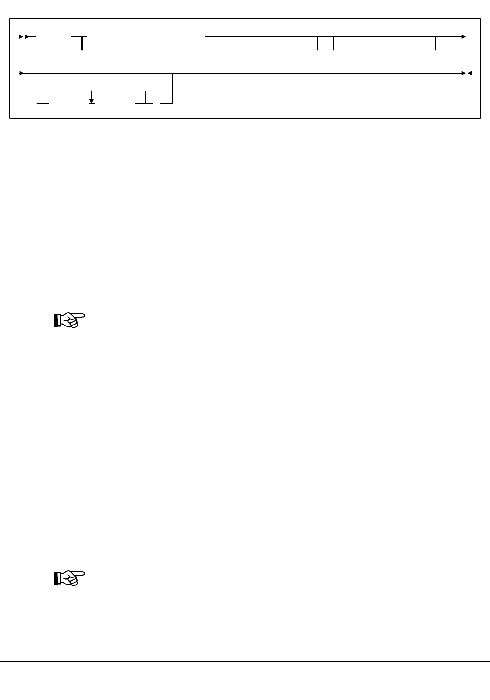
Chapter 3. HSC Control Statements and HSC Start Procedure 155
1st ed., 6/30/04 - 312579601
Syntax
Control Statement Name
VOLDEF
initiates the VOLDEF command and control statement.
Parameters
DATASET or DSN
specifies the name of the data set containing the VOLATTR statements to be
processed and, optionally, an OPTion TITLE statement. (Refer to “Volume Attribute
(VOLATTR) Control Statement” on page 143 and “OPTion TITLE Control
Statement” on page 113 for details on syntax and parameters).
Note: The definition data set may contain VOLATTR, UNITATTR, TAPEREQ, and
OPTion TITLE statements.
• Only OPTion TITLE and VOLATTR statements are processed.
• If any other statement is encountered, an error message is issued and the
statement is ignored.
dataset.name
is the name of the data set containing volume attribute parameters. If the data
set name includes a member name, dataset.name must be enclosed in quotes.
For example,
DATASET(‘YOUR.DSN(MEMBER)’)
VOLume
specifies the serial number of the DASD volume on which the data set resides. This
parameter is optional. Specify the VOLume parameter if the data set is not cataloged,
or if a data set on a volume other than the volume indicated by the catalog is to be
used.
Note: The volume specified must be a DASD volume.
volser
specifies the volume serial number for the definition data set.
VOLDEF
DSN(dataset.name)
DATASET(dataset.name)
VOLume(volser)UNIT(unitname)
HOSTID( host-id
,
)
VOLDEF

156 VM/HSC 6.0 System Programmer’s Guide
1st ed., 6/30/04 - 312579601
UNIT
specifies the unit where the definition data set is located.
unitname
specifies the unit name. If the definition data set is not cataloged and this
parameter is omitted, a unit name of SYSALLDA is the default.
HOSTID
(This parameter is valid only for use in PARMLIB, so that multiple systems can
share a PARMLIB member containing TAPEREQ, VOLATTR, or UNITATTR
statements for different releases of HSC. If entered from the console, message
SLS0018I is issued.)
Optionally, limits the execution of this control statement to the specified hosts. If one
of the specified hostids matches the host executing this control statement, the control
statement is executed for that host. Otherwise, it is ignored. If this parameter is
omitted, the control statement is executed on all hosts.
host-id
specifies the name of one or more hosts from which to execute this control
statement. Multiple hosts must be separated by commas.
Examples
The following examples illustrate the use of the VOLDEF statement.
Load the VOLATTR Parameters From YOUR.DSN(MEMBER)
Load the VOLATTR Parameters From DASD Volume DISK02
VOLDEF DSN(‘YOUR.DSN(MEMBER)’)
VOLDEF DSN(YOUR.DSN2) VOLUME(DISK02)
VOLDEF
Chapter 3. HSC Control Statements and HSC Start Procedure 157
1st ed., 6/30/04 - 312579601
Creating an SLKJCL File for Starting the HSC
An SLKJCL file must be created on the ACS191-disk. The ACS INIT command submits
the SLKJCL file. This loads the nucleus of the HSC into main storage, instructs the SCP to
allocate data sets, and invokes the library host software initialization routine.
Note: Refer to “EXECParm Control Statement” on page 90 for an alternative method of
specifying GTF Eid and Fid parameters. Also, see ‘‘HSC Initialization Parameters’’ and
‘‘HSCPARM’’ in the HSC Installation Guide.
This section describes how to create the SLKJCL file. A typical syntax for the /PARM
statement and full descriptions of each of the parameters follows.
/PARM Statement
Syntax
/PARM Statement Parameters
/PARM
defines the list of parameters passed to the HSC initialization routine.
Note: If you enter more than one of the following parameters, you must separate
them with a blank space (e.g., BASE SSYS(subsystem) RESET).
BASE
specifies that the HSC initialize and execute at the base service level.
/PARM BASE
SSYS(subsystem)
COLD
RESET
Eid(xxxx)
Fid(xx)
Member(xx)
Dialog( Off )
RECONFIG
Console
Log
Both

158 VM/HSC 6.0 System Programmer’s Guide
1st ed., 6/30/04 - 312579601
SSYS
specifies that HSC initialization search for the subsystem name specified. If SSYS is
specified, the name must match the LIBSUBSYS parameter value in the system
profile (SYSPROF). If the name is not found or is not a valid name, the subsystem
terminates. subsystem must be a 1- to 4-character name or problems can occur when
initializing the HSC.
This parameter permits you to symbolically specify the subsystem if the job name in
the startup SLKJCL file does not match the subsystem name.
Note: Either the job name or the SSYS value must match the subsystem name or the
HSC will not initialize.
COLD
specifies that any permanent in-memory data structures previously allocated by HSC
are reallocated and reinitialized.
On the first startup of the HSC after an IPL, this option is meaningless.
This parameter should be used only when absolutely necessary. (The installation
instructions for some HSC maintenance may direct you to perform a COLD start.)
Note: You do not need to include the COLD parameter when you are initializing an
HSC that is at a different release level than the HSC that was previously running on a
host. When an initializing HSC detects a release level difference, it performs an
automatic internal cold start.
Contact StorageTek Software Support before using this parameter (see the guide
Requesting Help from Software Support for more information).
RESET
specifies that all subsystem status flags in the Subsystem Communications Vector
Table (SSCVT) for the HSC are unconditionally reset. Use of this option may correct
a situation in which the HSC was terminated abnormally without resetting the status
flags.
One possible symptom of this situation is the message:
... ACS subsystem CCCC is ACTIVE
or
... ACS subsystem CCCC is TERMINATING
or
... ACS subsystem CCCC is INITIALIZING
at HSC startup, when a display of active jobs indicates that the subsystem is not, in
fact, active.

Chapter 3. HSC Control Statements and HSC Start Procedure 159
1st ed., 6/30/04 - 312579601
This parameter should only be used in extreme situations and may not correct all
error conditions. Contact StorageTek Software Support before using this parameter.
Eid
xxxx is 1 to 4 hex characters specifying the GTF event ID used for the duration of this
subsystem. ‘‘E’’ is the abbreviation for this parameter. The default Eid value is E086.
Fid
xx is 1 to 2 hex characters specifying the GTF format ID used for the duration of this
subsystem. ‘‘F’’ is the abbreviation for this parameter. The default Fid value is 17.
Note: Refer to “EXECParm Control Statement” on page 90 for an alternative method
of specifying GTF Eid and Fid parameters.
Member
For VM, xx is the suffix of an SLSSYSxx /FILE statement in the startup job to be
used as the automatic commands data set. This /FILE statement may define an MVS
sequential data set or PDS member, or it may define the last /FILE statement in the
startup job, specified as:
/FILE SLSSYSxx *
‘‘M’’ is the abbreviation for this parameter.
Dialog
specifies that messages can be displayed on the operator console and/or written to the
system log. These messages indicate that the HSC is waiting for an active task to
complete before the HSC terminates.
If Dialog is specified, one of the options must be selected. There is no default. The
options for Dialog include:
Off
specifies that you do not want active task termination messages displayed on
the operator console or written to the system log.
Both
specifies that messages are displayed on the operator console and written to the
system log. If Dialog is not specified, Both is the default. For more information
on Dialog, see ‘‘OPTION Command and Control Statement’’ in the HSC
Operator’s Guide.
Console
specifies that messages are displayed on the operator console only.
Log
specifies that messages are written to the system log only.
RECONFIG
specifies this execution of the HSC will only run the Reconfiguration utility.

160 VM/HSC 6.0 System Programmer’s Guide
1st ed., 6/30/04 - 312579601
HSC Startup Job (ACS SLKJCL)
Perform the steps in the following procedure to create the job file to be used to start the
library subsystem. It is later invoked in an AUTOJOB statement in the ACS SYSPROF
file.
1. Log on to MAINTSTK.
2. Issue the command:
ACS UTIL HSCINIT (NOSEND
3. When XEDIT displays the file, modify it as desired.
a. If the PARMLIB data set is shared with other hosts, specify the data set
information and delete the remaining lines. or
b. If PARMLIB statements and commands are to be specified in the startup
SLKJCL file, delete the first /FILE SLSSYSxx statement. Then do the
following:
1. Verify that the CDSDEF statement contains DSNx, VOLx, and UNITx
values for each control data set you want to define.
2. Verify that the JRNDEF statement contains DSNx, VOLx, and UNITx
values for each journal data set you want to define.
3. Delete any statements that are not required.
4. Modify or delete the startup commands provided to satisfy your site
requirements and add other commands as necessary. Refer to the HSC
Operator’s Guide for explanations of commands.
4. File it to the 191 disk when the file appears as desired.
5. Rename the file (if desired).
6. Copy the file to the MAINTSTK ACS191-disk.

Chapter 3. HSC Control Statements and HSC Start Procedure 161
1st ed., 6/30/04 - 312579601
Example
The following listing is an example job for the ACS INIT command.
Sample ACS SLKJCL File
/JOB jobname SLSBINIT
/PARM E(E086) F(17) MEMBER(xx)
/FILE SLSSYSXX DEV <vaddr> DSN <dsname><(member)>
/COMM If using a library with multiple hosts
/COMM modify the /FILE SLSSYSXX statement above
/COMM and delete the lines following it
/COMM Else delete the /FILE SLSSYSXX statement above
/COMM and use the following for initial parameters
/FILE SLSSYSXX *
/***************************************************/
/* */
/* Commands to execute automatically at startup: */
/* */
/***************************************************/
/* Set some options */
OPTion Output=<Upper|Mixed>
MNTD AUTocln=<OFf|ON>
MNTD Dismount=<Auto|Manual>
MNTD Scratch=<Auto|Manual>
/* Set CAP preferences */
CAPPref <prefvalue>,<cap!list>
/* Define control data sets */
CDSDEF DSN1=<prm.dsname>,VOL1=volunit1,UNIT1=unit1 !
DSN2=<sec.dsname>,VOL2=volunit2,UNIT2=unit2 !
DSN3=<stb.dsname>,VOL3=volunit3,UNIT3=unit3
Define journal data sets */
JRNDEF DSN1=<jrn1.dsname>,VOL1=volunit1,UNIT1=unit1 !
DSN2=<jrn2.dsname>,VOL2=volunit2,UNIT2=unit2 !
HOSTID=<hostid>
/* Define host!to!host communications */
COMMPath HOSTid=<hostid> METHod=vtam VTAMpath=<applid1> LMUpath=<00>
COMMPath HOSTid=<hst2> METHod=vtam VTAMpath=<applid2> LMUpath=<00>
/* Define scratch subpools */
SCRPOol NAME=<pool1> RANGE=<000300!000320> LABEL=<sl> HOSTID=<hostid>
/* Define scratch thresholds */
Warn SCRatch <00> SUBpool=<pool1> THReshld=<400>
/* Get LSMs online */
MODify <000> <ONline|OFFline>
MODify <001> <ONline|OFFline>
/* Display library status */
Display ALl
Display CDS

162 VM/HSC 6.0 System Programmer’s Guide
1st ed., 6/30/04 - 312579601
Notes:
1. The job name in the startup SLKJCL file must match the subsystem name specified
with the LIBSUBSYS parameter in the SYSPROF or it must be specified with the
SSYS parameter in the /PARM statement. Refer to “SSYS” on page 158 for more
information.
2. Control data sets are defined using the CDSDEF control statement. The CDSDEF
statement must be present in your PARMLIB definitions. Control and journal data
sets may no longer be defined in JCL. Refer to ‘‘CDS Definition (CDSDEF) Control
Statement’’ in the HSC System Programmer’s Guide for more information.
3. The number of CDS copies used by the HSC is dependent on the number of CDS
copies defined in the CDSDEF PARMLIB control statement. It is not determined by
the TCHNIQE parameter of the LIBGEN SLIRCVRY macro. The HSC uses all of
the CDS copies defined in the CDSDEF control statement (whether this includes
more or less CDS copies than are specified by the TCHNIQE parameter).
4. Journals are defined using the JRNDEF control statement. The JRNDEF statement
must be present in your PARMLIB definitions if you want to use journaling. Journal
data sets may no longer be defined in JCL. Refer to ‘‘Journal Definition (JRNDEF)
Control Statement’’ in the HSC System Programmer’s Guide for more information.
5. If journaling is specified by the TCHNIQE parameter of the LIBGEN SLILIBRY
macro, journals must be defined in your PARMLIB definitions for successful HSC
initialization.
Description of /FILE Statement
The following is a description of the JCL /FILE statement used in the example job for the
ACS INIT command.
SLSSYSXX
statement that defines the sequential data set or PDS member containing the
PARMLIB definitions.

163 VM/HSC 6.0 System Programmer’s Guide
1st ed., 6/30/04 - 312579601
Starting HSC Execution
Initialize the HSC. Refer to “Starting the HSC” on page 165 for information about how to
start execution of the HSC.
Note: The subsystem name specified with the LIBSUBSYS parameter in the SYSPROF
must match the jobname in the startup SLKJCL file or it must be specified with the SSYS
parameter in the /PARM statement. Refer to “SSYS” on page 158 for more information.
When phases of HSC initialization are completed, messages are displayed indicating
completion of the initialization phases. Messages inform you when HSC base service level
and when HSC full service level initialization is completed.
If SMF options for the HSC were not specified by a SET PERFlog command in the system
profile, the HSC issues a message that SMF record subtypes 1 through 6 are being
recorded.
If you did not specify GTF Eid and Fid parameters on the /PARM statement in the HSC
startup SLKJCL, HSC issues a message indicating that default Eid and Fid values are
being used.
HSC may be started prior to hardware arrival to ensure that it has been installed properly.
The HSC subsystem comes up with the LMU stations offline. HSC operator commands
may be entered, but any functions requiring interaction with the ACS hardware result in
error messages.
Modifying LSMs Online
When the CDS is initialized, the status of all LSMs defined in the LIBGEN is OFFLINE.
You must issue the HSC MODify ONline command to bring all of your LSMs online.
For subsequent executions of the HSC, the last recorded status of the LSMs is obtained
from the control data set.
Specifying CAP Preferences
When the CDS is initialized, all CAP preferences are zero (never selected). You must issue
the CAPPREF command and control statement to establish a preference value for a CAP.
The HSC selects CAPs based on the preference value. Refer to ‘‘CAP Preference
(CAPPref) Command and Control Statement’’ in the HSC Operator’s Guide for more
information.
Configuration Mismatches
During HSC initialization, the HSC remains active if LSM or panel type configuration
mismatches occur between the CDS and LMU. Specifically, these mismatches include:
• different numbers of LSMs
• different or unknown types of LSMs
• different or unknown panel types in an LSM.

164 VM/HSC 6.0 System Programmer’s Guide
1st ed., 6/30/04 - 312579601
In these cases, the affected ACS(s) is forced offline. The HSC continues to support the
unaffected ACS(s).
While the unaffected ACS(s) remains online, the mismatched configuration can be
corrected. If the hardware configuration is incorrect, the affected ACS(s) can then be
brought online. Otherwise, the configuration can be changed through the
LIBGEN/SLICREAT/Reconfiguration process at your convenience.
Multiple Hosts Startup Considerations
In a multiple-host configuration, start one host at a time. Do not bring up multiple hosts
simultaneously.

Chapter 3. HSC Control Statements and HSC Start Procedure 165
1st ed., 6/30/04 - 312579601
Starting the HSC
The HSC software can be initialized in three ways:
• Start the ACS service machine via the CP AUTOLOG command.
• Issue the ACS INIT command from the service machine virtual console.
• Submit the HSC startup SLKJCL to the ACS service machine, if the SCP is already
executing but without the HSC.
Parameters associated with the /PARM statement in the HSC startup SLKJCL (see
“Creating an SLKJCL File for Starting the HSC” on page 157) can also be supplied via a
PARM= option with the ACS INIT command and the ACS SUBMIT command.
Specifying the PARM= option appends the parameters specified to the parameters on an
existing /PARM statement, or creates a new /PARM statement. In this way, most of the
startup parameters can be overridden.
The HSC can be initialized to a full or base service level via parameters on an existing
/PARM statement in the startup SLKJCL, or by issuing the ACS INIT or ACS SUBMIT
commands with the PARM= option.

166 VM/HSC 6.0 System Programmer’s Guide
1st ed., 6/30/04 - 312579601
Initializing the HSC to the Full Service Level
Normally, HSC software is initialized to the full service level when it is started. The
syntax for the commands used to initialize the HSC to the full service level is shown
below.
Syntax for Initializing HSC to Full Service Level
AUTOLOG svmname pswd - or - ACS INIT - or - ACS SUBMIT strtjclfn strtjclft
strtjclfm libclass.
AUTOLOG svmname pswd
- or -
ACS INIT
- or -
ACS SUBMIT strtjclfn strtjclft strtjclfm libclass

Chapter 3. HSC Control Statements and HSC Start Procedure 167
1st ed., 6/30/04 - 312579601
Initializing the HSC to the Base Service Level
HSC software can be started to the base service level by adding the BASE parameter on
the /PARM statement of the startup SLKJCL, this includes specifying it on the ACS INIT
or ACS SUBMIT commands. When using the CP AUTOLOG command, the BASE
parameter must be specified on an existing /PARM statement in the startup SLKJCL. The
BASE parameter can be used with other parameters on the /PARM statement.
When the BASE parameter is specified in the startup SLKJCL, the syntax to initialize the
HSC to the base service level is the same as for initializing to the full service level.
When the BASE parameter is not specified in the startup SLKJCL, the commands used to
initialize the HSC to the base service level must include a PARM=BASE parameter.
Syntax for Initializing HSC to Base Service Level
After initializing to this point, the SRVlev command can be used to bring the subsystem up
to full function.
ACS INIT ( PARM=BASE
- or -
ACS SUBMIT strtjclfn strtjclft strtjclfm libclass ( PARM=BASE

168 VM/HSC 6.0 System Programmer’s Guide
1st ed., 6/30/04 - 312579601

Chapter 4. Utility Functions 169
1st ed., 6/30/04 - 312579601
Chapter 4. Utility Functions
Overview of Library Utilities
The HSC contains utility functions that provide you with ways to manage library
resources. Primary utility functions include:
• library CDS maintenance
• control of library cartridges
• control of scratch volumes
• preparation of reports covering library activity.
In addition, utilities contain the following attributes:
• Most are submitted to the SCP for execution, but some require or allow special
environments.
• Utilities submitted as batch jobs to the SCP require the use of special SCP JCL
(SLKJCL) statements.
• Specific utility functions are requested by special utility control statements which
define the function and supply all required parameters; these are distinct from JCL
statements.
Table 9. Utilities Overview
Function Utility
Library Control Data Set Maintenance AUDIt
BACKup
Database Decompile (LIBGEN)
Directory Rebuild (DIRBLD)
Journal Offload (OFFLoad)
RESTore
SET
Cartridge Control Eject Cartridge (EJECt)
Enter Cartridges (ENTer)
MOVe
UNSElect
Scratch Volume Control Scratch Redistribution (SCREdist)
Scratch Update (SCRAtch, UNSCratch, and REPLaceall)
Reporting Activities Report (ACTIvities)
Performance Log Reblocker (SLUPERF)
Volume Report (VOLRpt)

170 VM/HSC 6.0 System Programmer’s Guide
1st ed., 6/30/04 - 312579601
• The ACS UTIL exec can be used to generate a template for all required SLKJCL and
control statements for any utilities requested, and is recommended for beginners.
Selecting a Utility
There are many utilities described within this chapter. If you know what function you want
to perform, find that function in Table 10. The applicable utility for each specific function
is contained in the table.
Table 10. HSC Utilities and Functions
Function Utility to Use
Add a volume (or list of volumes) to the
existing scratch list contained in the
CDS
SCRAtch
Backup the library CDS BACKup
Balance the number of scratch volumes
across the library
Scratch Redistribution (SCREdist)
Clear (delete) the scratch list in the CDS
and optionally replace it with a new list
Replace (REPLaceall)
Delete a volume (or volumes) from the
scratch list contained in the CDS
UNSCratch or Replace (REPLaceall)
Eject one or more cartridges from an
ACS in batch mode
EJECt
Enter one or more cartridges into the
ACS in batch mode
ENTer
Force unselection of a volume selected
by the HSC
UNSElect
Inventory cartridges in the library AUDIt
Move or relocate a volume (or volumes)
within an ACS
MOVe
Off-load one or both of the journals Journal Offload (OFFLoad)
Prepare the SCP-generated performance
log (SMF data) for use by the Activities
Report utility
Performance Log Reblocker (SLUPERF)
Print a listing of volumes and locations
residing in an LSM
Volume Report (VOLRpt)
Print an activities report listing library
activity statistics
Activities Report (ACTIvities)
Rebuild the database directory if the
CDS becomes corrupted
Directory Rebuild (DIRBLD)
Recreate the library LIBGEN from the
existing CDS
Database Decompile (LIBGEN)
Chapter 4. Utility Functions 171
1st ed., 6/30/04 - 312579601
Note: If you are running a mixed multi-host complex of HSC 5.0, 5.1, and 6.0 systems,
refer to Appendix D, ‘‘Migration Process’’ in the HSC Installation Guide for the proper
utility release level.
Restore or recreate the library CDS RESTore
Set or change library configuration
information, including:
- ACS esoteric
- CDS level
- cleaning prefix
- delete disposition
- device numbers for drives
- eject password
- host identification
- HSC command prefix
- HSC level
- library station device numbers
- MAJNAME (QNAME)
- nonlibrary esoteric
- scratch label type
- SMF record type
- recovery technique
SET
Table 10. HSC Utilities and Functions (Continued)
Function Utility to Use

172 VM/HSC 6.0 System Programmer’s Guide
1st ed., 6/30/04 - 312579601
Typical Use of Utilities
A typical use of utility functions might be, for example, to enter some cartridges into the
library through the CAP using the Enter Cartridges utility, add scratch volumes to the CDS
by invoking the Scratch Update utility, and run the Volume Report utility to determine the
physical location of volumes in an LSM. In the following example
• cartridges are being entered through CAP 02
• volumes A1B1C1 through A1B1C4 have been designated as scratch volumes
• the volume report is being run for ACS 01, LSMs 0 and 1.
Note: /PARM MIXED in the JCL specifies mixed characters.
The JCL for invoking these utilities is:
It is only necessary to supply those statements required by the particular utility function(s)
being invoked. Utility functions can also share data sets represented by the same
statement.
For convenience, most utility programs can be run as a single-step batch job submitted to
the ACS service machine, otherwise known as the SCP environment. The submitted file
consists of SCP job control statements which define the files needed to run the
SLUADMIN program, and utility control statements which specify the desired utility
functions and parameters.
Any virtual machine that is authorized for commands to the ACS service machine may
submit library utilities. The file to be submitted is ‘‘punched and spooled’’ to the ACS
service machine’s ‘‘reader.’’ Within the SCP environment, utilities then run as batch jobs
under the SCP. The submitting virtual machine is notified (via console messages) when
the job begins execution, when it ends, and what the final return code is. The resulting
reports are then spooled back to the submitter.
Exceptions to this are these reporting utilities:
• Activities Report utility
• Performance Log Reblocker
• Volume Report.
The Activities Report utility runs in the CMS environment, and the Performance Log
Reblocker runs in either the CMS or MVS environments. Utilities that are run in the CMS
environment require CP LINK read access to the MAINTSTK RUN-disk.
/JOB jobname SLUADMIN
/PARM MIXED
/FILE SLSCNTL DEV vaddr DSN dsname
/FILE SLSPRINT DEV PRNT CLASS A
ENTER CAP(02)
SCRATCH VOLSER(A1B1C1,A1B1C2,A1B1C3,A1B1C4)
VOLRPT ACS(01) LSM(0,1)

Chapter 4. Utility Functions 173
1st ed., 6/30/04 - 312579601
The Volume Report utility executes in the SCP batch job environment in CMS, or in
stand-alone mode in the POST/SAE environment. Stand-alone mode allows the
administrator to locate backup tapes when the ACS service machine cannot be started due
to the loss of a critical DASD data set.
Control Statement Syntax Conventions
The control statement for each utility program consists of a command (indicating the
utility function) followed by parameters, as applicable, in 80-character card-image
records. For more information about this syntax, see Appendix A, “Macros, Control
Statements, Utilities, and Commands Syntax Reference” on page 429.
Utility Syntax Conventions
Utility syntax is illustrated using syntax flow diagrams. For a complete description of this
syntax convention, refer to Appendix A, “Macros, Control Statements, Utilities, and
Commands Syntax Reference” on page 429.
Utility Environmental Requirements
Most of the utility functions require the HSC (Host Software Component) to be
operational. However, a few are either independent of the HSC or have special
environmental requirements:
• The Backup utility and the Journal Offload utility require the ACS service machine
SCP to be available, but not the HSC.
• The Restore utility likewise requires the SCP to be available and also requires the
HSC to be non-operational.
• The Activities Report utility, the Performance Log Reblocker utility, and the Volume
Report utility run in the CMS environment and are independent of the HSC and the
SCP. The Performance Log Reblocker can also be run in the MVS environment.
Note: For systems running VM ESA Version 2 or higher, utilities that are run in
CMS can run in XA or XC mode with SET 370ACCOM ON. For VM ESA below
Version 2, utilities run in CMS must run in 370 mode.

174 VM/HSC 6.0 System Programmer’s Guide
1st ed., 6/30/04 - 312579601
ACS UTIL Exec
The most convenient way for a beginner to run the utilities is to use the ACS UTIL exec.
When provided with the names of the utilities to be executed, the ACS UTIL exec builds a
file containing the control statements required to execute these utilities in the appropriate
SCP or CMS environment. The file is then displayed for editing by the user who must then
fill in, or change the supplied template parameters. The exec then checks these parameters
for errors and submits the utility for execution.
The ACS UTIL exec may be used for any utilities that run in the SCP or CMS
environments.
More than one utility may be invoked at a time.
The ACS UTIL command has the following syntax:
EXEC ACS UTIL util!list
This command creates utility statements to execute all the utilities named in util-list. The
valid values that may be entered in the util-list are listed below and are also shown in the
utility syntax examples provided throughout the remainder of this chapter. The minimum
abbreviation is denoted by uppercase letters. Appendix A, “Macros, Control Statements,
Utilities, and Commands Syntax Reference” on page 429 contains a complete syntax for
all of the utilities.
ACTIVities Activity distribution report
ACTIVity Activity distribution report
AUDIT Audit library contents
BACKup Back up the library control data set
EJECt Eject a list of volumes
ENTEr Enter volumes through the CAP
HSCINIT Create HSC startup job
IVP1 JCL for Installation Verification
LIBGen Decompile the LIBGEN database
MOVe Move volume(s) to other locations in the library
OFFLoad Offload a journal data set
RECONfig Reconfigure the library subsystem
REPLaceall Replace the scratch volume list
RESTore Restore control data set from a backup
SCRAtch Change volumes to scratch status
SCREdist Scratch volume redistribution
Chapter 4. Utility Functions 175
1st ed., 6/30/04 - 312579601
CMS Environment
For utilities that run in the CMS environment, an edit session of an EXEC 2 file is
presented for you to modify. The file identifier is ACSCMS EXEC.
Note: For systems running VM ESA Version 2 or higher, utilities that are run in CMS can
run in XA or XC mode with SET 370ACCOM ON. For VM ESA below Version 2,
utilities run in CMS must run in 370 mode.
For example, entering:
EXEC ACS UTIL SLUACTV
produces the edit session display of this ACSCMS EXEC file:
ACSCMS EXEC
If you decide not to execute the utility, then enter the XEDIT command QUIT.
To execute the utility, perform the following steps:
1. Delete the lines in the template that are not required, or leave the comment indicator
(*) in column one.
2. Remove the comment indicator (*) from the desired lines.
3. Specify values for the desired parameters.
4. Delete the parameters that are not desired.
SET Change library configuration information
SLICREAT Library control data set creation
SLIMDisk Allocate an OS-format data set on a minidisk
SLIVInt Initialize a volume in OS format
SLSBINIT Create HSC startup job
SLUACtv Activity distribution report
SLUETRac Format trace records
SLUPErf Reblock performance log data
TRAce Format execution trace data
UNSCratch Change volumes to non-scratch status
UNSElect Unselect a volume that was left selected by HSC
VOLRpt Volume location report
&TRACE ALL
* EXEC SLUACTV <ctlfname|SLUACTV> <ctlftype|PARMS> <ctlfmode|*>

176 VM/HSC 6.0 System Programmer’s Guide
1st ed., 6/30/04 - 312579601
5. Enter the XEDIT command FILE. The file ACSCMS EXEC A is then executed to
run the utility, and the ACSCMS exec remains on the caller’s A-disk.
SCP Environment
For utilities that run in the SCP environment, job statements for the requested utilities are
constructed from parameters in the system profile (ACS SYSPROF). Parameter statement
templates are presented for the caller to edit. Only noncomment statements are processed
further.
For example, entering:
EXEC ACS UTIL AUDIT
produces an edit session display of this ACSUTIL SLKJCL file:
ACSUTIL SLKJCL file
This file provides templates for two AUDIT runs. The first is a complete audit of an entire
ACS (note that this would run many hours). The second provides all the parameters that
may be used to limit the scope of the audit. As initially presented, all control statements
are actually just comments.
If you decide not to execute the utility, then enter the XEDIT command QUIT.
To execute the utility, perform the following steps:
1. Delete the lines in the template that are not required, or leave the comment indicator
(*) in column one.
2. Remove the comment indicator (*) from the desired lines.
3. Specify values for the desired parameters.
4. Delete the parameters that are not desired.
5. Enter the command ‘‘FILE.’’
6. The job statements are then checked for errors, and if none are found, the file
ACSUTIL SLKJCL A is both saved on the user’s A-disk and submitted to the ACS
service machine to run as an SCP batch job (class U). The submitting virtual machine
is notified (via console messages) when the job begins execution, when it ends, and
what the final return code is. The resultant reports are then spooled back to the
submitter.
/JOB ACSUTIL SLUADMIN
/PARM MIXED
/FILE SLSPRINT DEV PRNT CLASS A
/FILE SLSIN *
* AUDIT ALL APPLY(YES)
* AUDIT ACS(acsid) LSM(lsm-list) PANEL(panel-list) CAP(capid)-
* ROW(row-list) COLumn(col-list) APPLY(YES)
Chapter 4. Utility Functions 177
1st ed., 6/30/04 - 312579601
JCL and Control Statements
Although the ACS exec can generate a template job file, the utility control statements (and
possibly the SCP JCL) must be modified by the user. To do this the user should have some
understanding of the format and function of these statements.
SCP Batch Job Control Language (JCL)
The function of the SCP Job Control Language is to provide enough information to the
SCP to execute the requested utility within the SCP batch job environment. It defines the
name of the job to be executed, the name of program module to execute, the specific files
to be used by the program, and perhaps some miscellaneous parameters.
The suggested file type is SLKJCL, and the file must consist of fixed, 80 column
card-image records, composed of the following job control statements:
/JOB jobname pgmname
/PARM parms ...
/COMM comments ...
/FILE fileopts ...
Note: With the exception of the /PARM statement values, all JCL statements are case
insensitive.
/JOB Statement
The /JOB statement must be the first statement in a file of Job Control statements known
as a job stream or JCL. It defines the name of the job (jobname), and the name of the
program module to be executed (pgmname). Typically this is SLUADMIN.
There must be one and only one /JOB statement per job stream.
jobname
the name of the job. It must be from 1 to 8 alphanumeric characters beginning with
an alphabetic character.
pgmname
the name of the program to be executed. It must be from 1 to 8 alphanumeric
characters beginning with an alpha. Program must be a module in one of the
SCP/HSC LOADLIBs.
/JOB jobname pgmname
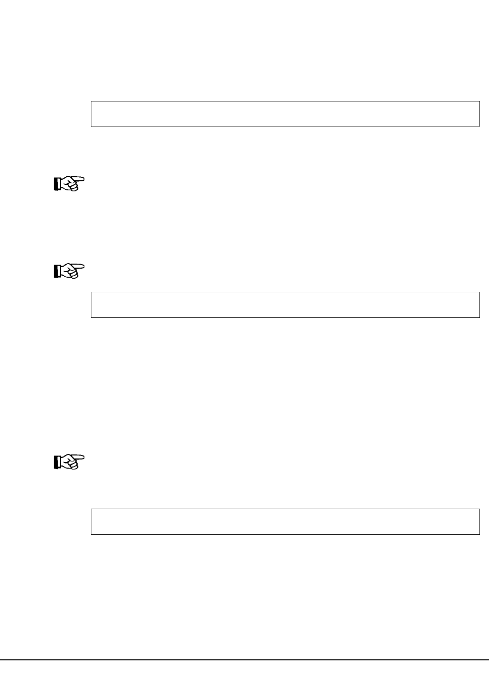
178 VM/HSC 6.0 System Programmer’s Guide
1st ed., 6/30/04 - 312579601
/PARM Statement
The /PARM statement supplies parameters for the program (pgmname). These parameters
and their format are program dependent.
There may be only one /PARM statement per job. If supplied, it must immediately follow
the /JOB statement.
parms
the parameters to be passed.
Note: Mixed case parameters will not be forced to uppercase.
/COMM Statement
A /COMM statement is a comment statement. It may be used only before or after /FILE
statements.
Note: After a ‘‘/FILE ddname *’’ statement, a /COMM statement is interpreted as data.
comments
comments of any format.
/FILE Statement
The /FILE statement describes a file to be used by the job. The parameters are identical to
the FILE command, described in the HSC Operator’s Guide.
There may be zero or more /FILE statements.
Note: A ‘‘/FILE ddname *’’ statement defines a file of user-data card-image records that
begins with the next record and continues until end-of-file. This type of /FILE statement
must be the last JCL statement in the job file.
fileopts
FILE command parameters.
/PARM parms
/COMM comments
/FILE fileopts

Chapter 4. Utility Functions 179
1st ed., 6/30/04 - 312579601
Submitting Jobs
Jobs may be submitted to the ACS service machine in several ways.
1. One method is to use ACS EXEC. This method does not require that the sender
knows the protocol or the name/node of the ACS service machine. It is the
recommended technique.
EXEC ACS SUBMIT fname ftype fmode class
fname
the CMS filename of the job file.
ftype
the CMS filetype of the job file. If omitted, it defaults to ‘SLKJCL’.
fmode
the CMS filemode of the job file. If omitted, it defaults to ‘‘*’’.
class
the job class desired. If omitted, it defaults to ‘‘U’’.
Note: These jobs must be submitted in job class L:
• HSC startup (HSCINIT, SLSBINIT)
• RECONFIG
2. From a virtual machine on the same host:
CP SPOOL PUN acsname NOCONT NOHOLD CLASS class
PUNCH fname ftype fmode (NOHeader
acsname
the name of the ACS service machine
3. From a virtual machine on another network node:
CP SPOOL PUN RSCS NOCONT NOHOLD CLASS class
CP TAG DEV PUN nodename acsname
PUNCH fname ftype fmode (NOHeader
acsname
the name of the ACS service machine
nodename
the name of the RSCS network node where the service machine resides

180 VM/HSC 6.0 System Programmer’s Guide
1st ed., 6/30/04 - 312579601
Utility Control Statements
Control Statements vs. JCL
In contrast to the SCP Job Control Language, the utility control statements are processed
only by the executed utility, not by the SCP. They supply all the specific parameters
required to execute a utility program (that is, function, cartridge VOLSER, location, etc.).
Briefly then, a control statement consists of a command (indicating the utility function)
followed by zero or more parameters in 80 column card-image records. A complete syntax
for the statements can be found in Appendix A, “Macros, Control Statements, Utilities,
and Commands Syntax Reference” on page 429.
Sample SCP Batch Job File - JCL and Control Statements
The ACS UTIL command used to create a template for invoking three utility functions
(first a Scratch Update utility, followed by an Audit utility against one Library Storage
Module [LSM], and finally a Volume Report) is:
EXEC ACS UTIL SCRATCH AUDIT VOLRPT
A sample job file might appear as follows:
Note: It is only necessary to supply those /FILE statements required by the particular
utility function(s) being invoked. Utility functions can also share data sets represented by
the same /FILE statement.
/JOB jobname SLUADMIN
/FILE SLSPRINT DEV PRNT CLASS A
/FILE SLSIN *
* SCRATCH VOLSER(vol-list)
* AUDIT ALL APPLY(YES)
* AUDIT ACS(acsid) LSM(lsmlist) PANEL(panel-list) CAP(capid) -
* ROW(row-list) COLUMN(col-list) APPLY(YES)
* VOLRPT ACS(acsid) LSM(lsmlist)
* VOLRPT VOLSER(vol-list)

Chapter 4. Utility Functions 181
1st ed., 6/30/04 - 312579601
Utility Administrator (SLUADMIN)
The SLUADMIN program operates as a batch job and controls initialization processing
for most utility functions. The utility administrator (SLUADMIN) can accept multiple
control statements which are handled as serial requests for multiple utilities. If all
requirements needed to execute the utility function are met, control is passed to the
appropriate program which handles the actual processing.
Utility functions represented by additional control statements are not started until the prior
utility function stops and control is returned to the SLUADMIN program.
How to Invoke SLUADMIN
The following is a generic example of JCL that can be modified to execute SLUADMIN.
Where ‘‘utility statements’’ appears in this sample JCL, enter the utilities you want to
execute.
For example:
SET HOSTID(HSC2) FORHOST(HSCB)
OFFLoad
SCREdist ACS(01)
JCL to Invoke SLUADMIN
/JOB jobname
/PARM MIXED
/FILE SLSPRINT DEV PRNT CLASS A
/FILE SLSIN *
utility statements
.
.
.

182 VM/HSC 6.0 System Programmer’s Guide
1st ed., 6/30/04 - 312579601
How to Invoke Utility Programs
For convenience, most utility programs are packaged to appear as a single, user-invoked
program. The Performance Log Reblocker utility is an exception.
All other utility functions are invoked as a normal batch job using the SLUADMIN
program and user-specified control statements needed to invoke the required utility
function.
Utility functions represented by additional control statements are not started until the prior
utility function stops and control is returned to the SLUADMIN program.
SLUADMIN Program Return Codes
The SLUADMIN program sets a return code for the execution of the job step as defined in
Table 11.
The return code for each utility function is listed in a message. For return codes other than
0, additional messages are listed providing more information and description of the error
condition. Refer to the HSC Messages and Codes Guide for any messages encountered.
Examples of utility program outputs, including messages indicating the return codes, are
provided throughout this chapter.
Table 11. SLUADMIN Return Codes
Return Code Description
0 All utility functions requested via control statements
completed normally.
4 At least one utility function encountered an abnormal
situation, but it did not cause termination of that utility
function or any subsequent utility functions.
8 At least one utility function encountered an error
condition that prevented continuation of that utility
function, but any subsequent utility functions represented
by control statements were attempted.
12 An error condition was detected that either prevented the
start of any utility functions, or terminated the active
utility function and prevented processing of subsequent
utility functions.
Note: If the return code occurred because of a problem
with the HSC CDS or journal files, the problem must be
resolved before the HSC can be initialized safely.

Chapter 4. Utility Functions 183
1st ed., 6/30/04 - 312579601
Reports Created by Utilities
Several utilities produce reports when executed. The reports are in addition to the utility
function. Utilities that produce reports include:
• Activities Report
• AUDit
•BACKup
•MOVe
• Volume Report.
A description of each utility and resulting report is contained in this chapter.
Report Headings
Utilities provide reports at the end of execution. Report headings include the following
information:
• date/time of the report,
• page number(s),
• host software version number, and
• name of the utility function executed.
Parameters Controlling Report Headings
There are two optional parameters that change the format of output reports.
Parameter Description
NOHDR Suppresses printing of report headings (error messages still
can be written to the report file). This can be useful when
running the Volume Report utility with the VOLDATA
parameter specified, which produces a raw volume (flat)
data file.
This parameter can be used only with the Activities Report,
MOVe, and Volume Report utilities.
NOHDR and LINECNT are mutually exclusive.
If NOHDR is not specified, the default is to print headings
containing the following information:
• date/time of the report
• page number(s)
• host software version number
• name of the utility function executed.
MIXED Prints all report headings and messages in mixed case. The
default is uppercase.
LINECNT=nn Specifies the number of lines per page for the SLUADMIN
report. Allowable values are 10 through 99; the default is
60 lines per page. LINECNT and NOHDR are mutually
exclusive.

184 VM/HSC 6.0 System Programmer’s Guide
1st ed., 6/30/04 - 312579601
Note: The DATE parameter does not control report header date formats, which are
displayed as yyyy-mm-dd. See Figure 9 on page 197 for an example of this format.
Example
Several JCL examples using the options for report headings follow:
Example of JCL Using Report Heading Options
DATE=2YR Specifies that all dates displayed in report detail lines are in
the ‘‘mm/dd/yy’’ format. A yy value of 71 or greater
indicates a 20th century (19xx) date. A yy value of 70 or
less indicates a 21st century (20xx) date. To avoid
confusion, you are encouraged to use the DATE=4YR
parameter setting described below.
DATE=4YR Specifies that all dates displayed in report detail lines are in
the ‘‘yyyymmdd’’ format. This is the default.
//STEP1 EXEC PGM=SLUADMIN,PARM=‘NOHDR,MIXED’
//STEP1 EXEC PGM=SLUADMIN,PARM=‘LINECNT=55’
//STEP1 EXEC PGM=SLUADMIN,PARM=‘MIXED’
//STEP1 EXEC PGM=SLUADMIN,PARM=‘DATE=4YR’

Chapter 4. Utility Functions 185
1st ed., 6/30/04 - 312579601
Stand-Alone Utilities
Most of the utility functions require the Host Software Component (HSC) to be up and
functional. Some utilities run stand-alone, in the sense that they perform no dialogues with
other HSC components, but they do require the VM Operating System to be available and
some require the SCP to be running. These stand-alone utilities are:
• Activities Report
•BACKup
• Database Decompile
• Directory Rebuild
• Journal Offload
• RESTore, which requires the HSC to be quiesced
• Volume Report.
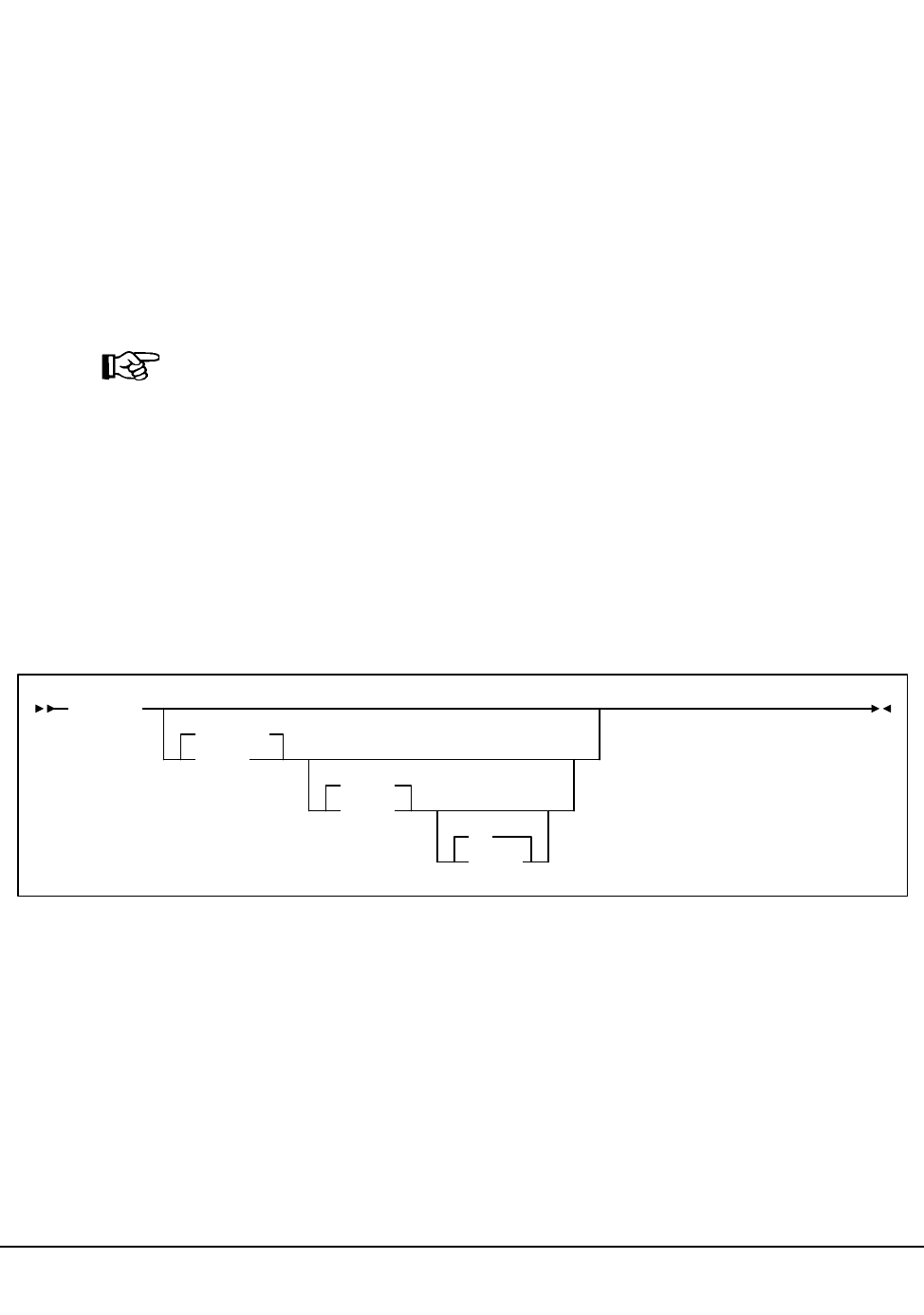
186 VM/HSC 6.0 System Programmer’s Guide
1st ed., 6/30/04 - 312579601
Activities Report Utility
The Activities Report utility provides you with information to analyze library resource
loading by volume groups (for example, scratch compared to nonscratch, mounted,
dismounted, entered, and ejected). This report provides the information necessary for
analyzing and possibly redistributing library resources. You specify the time period to be
reported against.
The utility executes in the CMS environment using the SLUACTV exec.
SLUACTV EXEC
The SLUACTV EXEC is the means to execute the library Activities Report utility in the
CMS environment.
Note: In the CMS environment, this utility can report only on SMF data created by the
library when running in the StorageTek SCP environment.
The Performance Log Reblocker (SLUPERF) utility must be run prior to executing the
Activities Report utility. Parameters are passed to the utility in a control file (SLUACTV
PARMS). These parameters include:
• parameters (/PARM) to pass to the utilities driver
• the name and location of the library’s primary control data set
• the destination of the report output
• the names of files containing SMF data to be reported on
• the date/time range that is to be reported.
fname
the CMS filename of the control file. The file must be fixed-format, record length 80.
The default is SLUACTV.
type
the CMS filetype of the control file. The default is PARMS.
fmode
the CMS filemode of the control file. The default is A1.
The control file must be fixed-format, record length 80, and must contain the following
statements:
SLUACTV
SLUACTV
fname
PARMS
ftype
A1
fmode
Activities Report

Chapter 4. Utility Functions 187
1st ed., 6/30/04 - 312579601
PARM
parameters to the SLUADMIN program that drive the utility.
MIXED
specifies that output is to be mixed case. The default is uppercase.
NOHD
specifies that page headers are not to be printed. The default is to print page
headers.
SLSCNTL vaddr DSN dsname
specifies the name of the library’s primary control data set (dsname). The default is
obtained from the ACS SYSPROF file. The caller must have the volume it is on
accessible as the given device address (vaddr). This parameter is required so that the
SMF record type code may be retrieved.
SLSPRINT DISK fname ftype fmode or SLSPRINT PRINTER
identifies the definition of the output file to be produced. The output may either go to
the named file or directly to a print spool file. This file contains the output messages
and report from the utility.
SLSSMF fname ftype fmode
identifies the names of the SMF data files (output by the SLUPERF utility) to be
examined. The filename specified will be used as a parameter to the CMS LISTFILE
command to produce a list of all qualified files. See the documentation for that
command for details on special wildcard symbols which may be used.
SLSIN ACTIvities parms
specifies the input to the utility taken from the parameter list that follows (see
‘‘Syntax’’ and ‘‘Parameters’’ below).
Activities Report
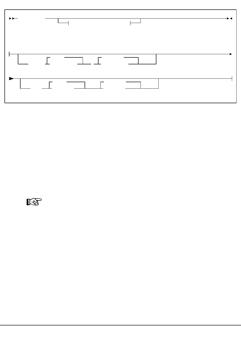
188 VM/HSC 6.0 System Programmer’s Guide
1st ed., 6/30/04 - 312579601
Syntax
Utility Name
ACTIvities
specifies that an activities report is to be produced.
Parameters
BEGIN
optionally specifies the beginning of the period for the activities analysis.
begin-date
begin-date specifies the starting date of the analysis, expressed in mm/dd/yy or
yyyymmdd format.
Note: When using the mm/dd/yy format, specify a yy value of 71 or greater to
indicate a 20th century (19xx) date. Specify a yy value of 70 or less to indicate a 21st
century (20xx) date. To avoid confusion, you are encouraged to use the yyyymmdd
date format.
TODAY
is default date.
begin-time
begin-time is the beginning time-of-day (24-hour value), expressed in hh:mm:ss
format.
The allowable range for the begin-time and end-time parameters is 00:00:00 to
24:00:00.
00:00:00
The default value is 00:00:00.
ACTIvities
Optional Parameters
Optional Parameters:
BEGIN( begin-date
TODAY
,begin-time
00:00:00
END( end-date
TODAY
end-time
23:59:59
Activities Report

Chapter 4. Utility Functions 189
1st ed., 6/30/04 - 312579601
Examples:
In each of the following examples, activity reporting begins on October 27, 1997 at
midnight.
BEGIN(10/27/97,00:00:00
BEGIN(19971027,00:00:00)
BEGIN(TODAY,00:00:00)
BEGIN(,00:00:00)
END
optionally specifies the end of the period for the activities analysis.
end-date
end-date specifies the ending date of the analysis, expressed in mm/dd/yy or
yyyymmdd format. If begin-date is specified, end-date must be in the same
format.
Note: When using the mm/dd/yy format, specify a yy value of 71 or greater to
indicate a 20th century (19xx) date. Specify a yy value of 70 or less to indicate a
21st century (20xx) date. To avoid confusion, you are encouraged to use the
yyyymmdd date format.
TODAY
is default date.
end-time
end-time is the ending time-of-day (24-hour value), expressed in hh:mm:ss
format.
The allowable range for the begin-time and end-time parameters is 00:00:00 to
24:00:00.
23:59:59
The default value is 23:59:59.
Examples:
END(10/27/93,18:00:00)
END(19960501,11:30:00)
END(TODAY,23:29:00)
END(,23:59:59)
Activities Report
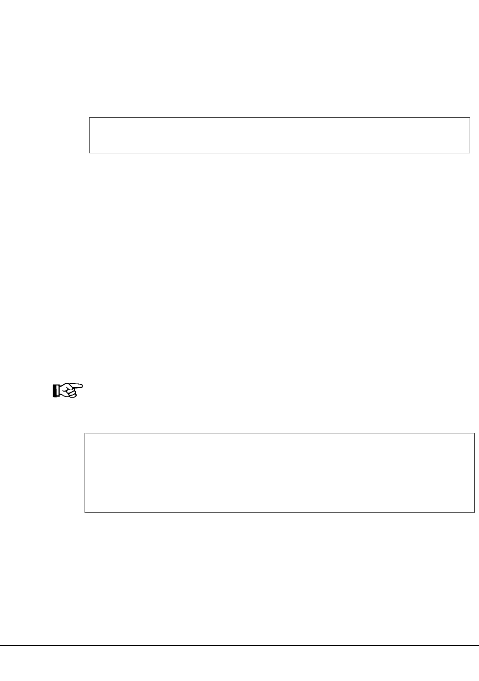
190 VM/HSC 6.0 System Programmer’s Guide
1st ed., 6/30/04 - 312579601
Invoking the Activities Report Utility
To invoke the Activities Report utility in VM, enter:
EXEC ACS UTIL ACTIVities
Execution of the statement results in the following ACSCMS EXEC file:
ACSCMS EXEC
To execute the ACTIvities utility:
1. Remove the comment indicator (*) on the left, and specify the name of the control
file to be used to specify the actual utility parameters.
2. Enter the ‘‘FILE’’ command after the previous step is done.
3. The named file (or the default control file) will then be presented to the caller for
modification.
4. Change any statements, then enter ‘‘FILE.’’
Control File Example
The following example shows a control file for producing an Activities report beginning
on December 2, 1999 at noon. Since the END parameter is not specified, all activity up to
the last record in the SLSSMF data set is reported. (This assumes that all SMF data is after
the start time.)
Note: An Activities Report is run from a control file in the invoker’s virtual machine
rather than as JCL in SCP.
Control File to Produce an Activities Report
Output Description
There are two types of output contained in the Activities report:
• statistics on cartridge movements (the first section of the report; called the Move
section of the report)
• statistics on overall ACS activity (the second section of the report, called the ACS
section of the report).
&TRACE ALL
* EXEC SLUACTV <ctlfname|SLUACTV> <ctlftype|PARMS> <ctlfmode|*>
* Parameters for SLUACTV EXEC
PARM MIXED
SLSCNTL 5F0
SLSPRINT DISK SLUACTV SLSPRINT A
SLSSMF * PERFLOG A
SLSIN ACTIVITIES BEGIN (12/02/99,12:00:00)
Activities Report

Chapter 4. Utility Functions 191
1st ed., 6/30/04 - 312579601
Cartridge Movement Statistics - Move Section of the Report
In the first section of the report, the Move section, the HSC provides two summary lines:
• The first summary line lists from 1 to 16 SMF system IDs found in the SMF records
input to the utility.
• The second summary line lists the SMF record type being reported, the total number
of SMF records, and the date (mm/dd/yy or yyyymmdd) and time (hh:mm:ss) of the
earliest and latest SMF record found matching the duration criteria.
The HSC SMF record type can be changed. When changed, the data extracted from
SMF represents the most recent SMF record type, and records with prior SMF record
types are ignored.
The duration criteria are specified in the Activities Report utility syntax as input via
the SLSIN parameters.
For the Move section of the Activities Report, every move type is reported under the
following headings:
Total
is the count of all operations for the move category listed found in the SMF input
matching the duration criteria.
This is calculated as the sum of the number of operations found in the SMF records
for the move category.
The value is reported as a count of moves and can range from 0 to 99,999,999,999
moves.
The major move categories are:
• all mounts (includes cleaning mounts)
• all dismounts (includes cleaning dismounts)
• all enters
• all ejects.
Subcategories for mount/dismounts are:
• scratch - same LSM
• scratch - diff LSM
• nonscratch - same LSM
• nonscratch - diff LSM.
Subcategories for enter/ejects are:
• ejects-same LSM
•ejects-diff LSM
• enters-same LSM
• enters-diff LSM.
Activities Report

192 VM/HSC 6.0 System Programmer’s Guide
1st ed., 6/30/04 - 312579601
All ‘‘-same LSM’’ subcategories report moves which have the source and
destination of the move in the same LSM. All ‘‘-diff LSM’’ subcategories report
moves which have the source and destination of the move in different LSMs.
% of all
is the percent of move operations represented by the category or subcategory found
in SMF input matching the duration criteria.
This percentage is calculated as the number of operations in the category or
subcategory divided by the number of operations in the major category.
The value is reported as a percent and can range from 0 to 100 percent.
Ave. time
is the mean elapsed time from the issuance of the move request by the HSC until the
HSC receives an acknowledgment that the cartridge has been moved.
It is calculated as the sum of the elapsed time for operations in the category divided
by the number of operations in the category. The elapsed time is an HSC determined
response time for a move request.
The value is reported as seconds and can range from 0.0 to 9,999.9 seconds. A value
of ‘‘N/A’’ indicates no SMF records were found for the move category or no library
hardware existed which matched the requested duration criteria.
For dismounts, this includes time for the transport to rewind and unload the cartridge.
For mounts, this includes time the transport takes to load and spin the tape to load
point. For mounts and dismounts, this excludes HSC queueing incurred when the
HSC delays sending a mount request to the LMU until a previous tape has been
rewound, unloaded, and put away.
Temporary enters are counted in the enter category. Ejects of temporarily entered
volumes are counted in the eject category. For temporary enter/ejects, transport load
and unload times are included in the elapsed time.
For enters and ejects, this only includes time it takes to move a cartridge from the
CAP to a cell or from a cell to the CAP. It does NOT include time it takes for an
operator to service the CAP or for the LSM to scan the CAP. It also excludes HSC
queueing done to manage the CAP activity.
Ave. pass-thrus
is the mean number of pass-thrus for a move category.
This is calculated as the sum of the number of pass-thrus divided by the number of
operations in the category.
The value is reported as the mean number of pass-thrus and can range from 0.0 to
99.9 pass-thrus.
This is only reported for the major and the ‘‘-diff LSM’’ move subcategories. A
value of ‘‘N/A’’ is reported for the ‘‘-same LSM’’ subcategories.
Activities Report

Chapter 4. Utility Functions 193
1st ed., 6/30/04 - 312579601
Earliest
is the date (mm/dd/yy or yyyymmdd) and time (hh:mm:ss) of the earliest SMF record
found matching the category being reported for the duration requested.
Latest
is the date (mm/dd/yy or yyyymmdd) and time (hh:mm:ss) of the last SMF record
found matching the category being reported for the duration requested.
Usage Notes
1. Only cartridge moves involving a CAP or a transport are reported. Cell to cell moves
such as those used by the Scratch Redistribution utility are not reported.
2. Only moves which complete successfully are reported in the statistics. Moves which
incur HSC or LMU errors are not reported.
3. Other products exist which report mount pending time, but fail to consider dismount
as a separate activity. To compare the Activities Report values to other products’
‘‘mount pending’’ time, it may be necessary to add HSC reported mount and
dismount times.
4. Other LSM operations besides cartridge moves consume ACS resources (e.g., CAP
and audit scans probably take the next highest amount of LSM activity depending on
frequency). Scans are not reported specifically, except as they impact cartridge
movement time and increase LSM ARM USE (see “Overall ACS Statistics - ACS
Section of the Report” on page 195).
5. The LSM may move more than one cartridge at a time and often interleaves moves
when busy. The HSC reported response time is an elapsed time which does not
consider overlapped operations. When attempting to determine how the LSM is
capable of mounting 10 cartridges in 125 wall clock seconds when the HSC reports
average mount time of 25 seconds, LSM interleave must be considered.
6. Dismount scratch categories depend on the LIBGEN SLILIBRY macro DELDISP
parameter. A scratch dismount occurs whenever the HSC detects a ‘‘delete’’
dismount and the library is LIBGENed with SLILIBRY macro parameter
DELDISP=SCRTCH. If this defaults to or specifies DELDISP=NOSCRTCH, then
there are no scratch dismounts.
Activities Report

194 VM/HSC 6.0 System Programmer’s Guide
1st ed., 6/30/04 - 312579601
7. As the HSC attempts to float dismounts to a nearby LSM, there should be less
pass-thru activity on dismounts than on mounts. However, to float cartridges, free
cells must be available. Ejects also may incur more pass-thru activity than enters
because the HSC attempts to place entered cartridges into the same LSM as the entry
CAP. Ejected cartridges may take numerous pass-thru operations to move from their
home cell to the preferred CAP.
8. The Activities Report summarizes information contained in SMF input. Two types of
SMF records are written every HSC SMF interval:
• LSM operating statistics record, (subtype 1), and
• LMU statistics buffer data block records (subtype 4).
The Move section of the Activities Report only processes the LSM operating
statistics records. LSM operating statistic records contain information describing
moves which complete during an HSC SMF interval. When attempting to understand
ACS performance it may be worthwhile to decrease the HSC SMF interval so the
HSC SMF records describe finer intervals of time (see ‘‘Adding SMF Parameters’’
HSC Installation Guide).
For the ACS section of the Activities Report, output is based on an LMU interval. In a
single host environment, the LMU interval is equivalent to the customer-defined HSC
SMF interval.
In a multi-host environment, the LMU interval for each host is equivalent to the
customer-defined HSC SMF interval for the host on which the HSC is running. In this
case, data from all hosts must be combined to get an accurate picture of HSC activity.
Combining data is necessary because the LMU’s reports of robotic motions and temporary
error counts are not separated by the requesting host. Robotic motions and temporary error
counts attributed to all hosts are combined and sent to the host that is currently requesting
ACS statistics.
In addition, in a multi-host environment, cartridge motions initiated for one host may be
accounted for in another host’s SMF data, depending on the relative length and timing of
the SMF reporting intervals on the various hosts. This is true for data that appears in PM2
and CA-9 Reliability Plus (R+) reports, as well as in this report. The SMF subtype 7
records generated for each motion request are reported only by the host that initiated the
request.
Note: For this report and for the CA-9 (R+) report, it is better to combine data from
multiple hosts prior to generating the report so that the data from all sources will be
reported and the totals and averages listed will be as accurate as possible.
Activities Report

Chapter 4. Utility Functions 195
1st ed., 6/30/04 - 312579601
Overall ACS Statistics - ACS Section of the Report
For the ACS section of the Activities report, ACS statistics are reported under the
following report headings:
ACS ID
is the ACS number of the ACS being reported, the number of SMF records, and the
earliest and latest SMF record date (mm/dd/yy or yyyymmdd) and time (hh:mm:ss)
found matching the Activities Report verbs duration specification.
LSM
the LSM numbers are listed across the page.
ARM USE
is the mean percent LMU calculated LSM arm busy found in the SMF input
matching the duration criteria.
The LMU calculates this value as the amount of time since start of an LMU interval
the LSM arm has been in motion divided by the total time in the LMU interval. This
value is then summed for all SMF records and divided by the number of SMF records
found matching the duration criteria.
The value is reported as a percent and may range from 0 to 100 percent. A value of
‘‘N/A’’ indicates the LSM is not configured. A value of ‘‘X percent’’ indicates that
the LSM is configured, but no SMF records matched the duration criteria.
LSM arm motion is used for CAP and audit scans as well as general cartridge
movement. This does not include pass-thru port rotation time, but does include time
to place the cartridge into the pass-thru port or to remove a cartridge from the
pass-thru port.
P-THRU
is the LMU calculated number of master pass-thru operations found in the SMF
records matching the duration criteria.
This is recorded by the LMU every LMU interval and is summed by the Activities
Report.
The value is reported as a count of pass-thrus and can range from 0 to 99,999
pass-thrus. A value of ‘‘N/A’’ indicates the LSM is not configured. A value of ‘‘X’’
indicates that the LSM is configured, but no SMF records matched the duration
criteria.
Each pass-thru port has both a master and a slave LSM. A pass-thru operation
involves placing a cartridge into one side of a pass-thru port, rotating the pass-thru
port, and removing the cartridge from the other side of the pass-thru port. Each
pass-thru operation is counted one time and is only counted by the master side LSM
for the pass-thru port.
Activities Report

196 VM/HSC 6.0 System Programmer’s Guide
1st ed., 6/30/04 - 312579601
Usage Notes
1. Merging multi-host HSC SMF records impacts the LSM ARM USE statistic as
described above. However, not merging multi-host HSC SMF records affects the
number of pass-thrus reported, as this is only the number of pass-thru operations
occurring during the hosts LMU interval.
2. LSM ARM USE should never be reported higher than 100 percent. If the LSM is
overlapping operations the arm is still only busy for 1 second even though it may be
moving two cartridges during that 1 second time period.
3. The raw SMF record contains counts of pass-thru operations for each master
pass-thru port of an LSM. The ACS section totals this information for its pass-thru
count.
4. The ACS section of the Activities Report only processes the LMU statistics buffer
data block SMF record (subtype 4). LMU statistics buffer records contain
information calculated and returned by the LMU every HSC SMF interval. When
attempting to understand ACS performance it may be worthwhile to decrease the
HSC SMF interval so the HSC SMF records describe finer intervals of time (refer to
‘‘Adding SMF Parameters’’ in the HSC Installation Guide).
5. Depending on the 9740 microcode level, 9740 LSMs may display zeroes for LSM
arm use percentage and pass-thru statistics. Additionally, the SLSSLSB SMF record
(refer to “SLSSLSB” on page 513) will contain zeroes in the LMU ATHS Statistics
Buffer entries, and the SLSSLLG6 LOGREC record (refer to “SLSSLLG6” on page
548) will not write robotics motion and soft fail counts for 9740s.
Figure 9 on page 197 is an example of a typical Activities report.
Activities Report

Chapter 4. Utility Functions 197
1st ed., 6/30/04 - 312579601
SLUADMIN (n.n.n) StorageTek Automated Cartridge System Utility PAGE 0001
TIME hh:mm:ss Control Card Image Listing DATE yyyy-mm-dd
ACTIVITIES BEGIN(20040301)
SLUADMIN (n.n.n) StorageTek Automated Cartridge System Utility PAGE 0002
TIME hh:mm:ss Activities Begin 2004-03-01 DATE yyyy-mm-dd
SYSTEM IDS: HSC1 HSCH HSCF HSCE HSC6 HSC2
SMF RECORD TYPE: 245 TOTAL RECORDS: 1,580 EARLIEST 20040301 11:54:12 LATEST: 20040401 05:12:25
TOTAL % OF ALL AVE.TIME AVE. PASS-THRUS EARLIEST LATEST
ALL MOUNTS: 346 100% 22.4 SEC. 0.0 20040301 11:54:12 20040401 05:12:25
SCRATCH -SAME LSM 10 0% 19.7 SEC. N/A 20040301 11:54:12 20040401 05:12:25
-DIFF LSM 0 0% N/A 0.0 20040301 11:54:12 20040401 05:12:25
NONSCRATCH-SAME LSM 336 97% 22.5 SEC. N/A 20040301 11:54:12 20040401 05:12:25
-DIFF LSM 0 0% N/A 0.0 20040301 11:54:12 20040401 05:12:25
TOTAL % OF ALL AVE.TIME AVE. PASS-THRUS EARLIEST LATEST
ALL DISMOUNTS: 345 100% 19.9 SEC. 0.0 20040301 11:54:12 20040401 05:12:25
SCRATCH -SAME LSM 0 0% N/A N/A 20040301 11:54:12 20040401 05:12:25
-DIFF LSM 0 0% N/A 0.0 20040301 11:54:12 20040401 05:12:25
NONSCRATCH-SAME LSM 345 100% 19.9 SEC. N/A 20040301 11:54:12 20040401 05:12:25
-DIFF LSM 0 0% N/A 0.0 20040301 11:54:12 20040401 05:12:25
TOTAL % OF ALL AVE.TIME AVE. PASS-THRUS EARLIEST LATEST
ALL ENTERS: 338 100% 12.2 SEC. 0.0 20040301 11:54:12 20040401 05:12:25
-SAME LSM 338 100% 12.2 SEC. N/A 20040301 11:54:12 20040401 05:12:25
-DIFF LSM 0 0% N/A 0.0 20040301 11:54:12 20040401 05:12:25
TOTAL % OF ALL AVE.TIME AVE. PASS-THRUS EARLIEST LATEST
ALL EJECTS: 338 100% 13.2 SEC. 0.0 20040301 11:54:12 20040401 05:12:25
-SAME LSM 326 96% 12.5 SEC. N/A 20040301 11:54:12 20040401 05:12:25
-DIFF LSM 12 4% 32.7 SEC. 1.0 20040301 11:54:12 20040401 05:12:25
ACS ID: 00 USAGE RECORDS: 690 EARLIEST: 20040301 11:54:12 LATEST: 20040401 05:12:25
LSM: 0 1 2 3 4 5 6 7 8 9 A B C D E F
ARM USE: 0% N/A N/A N/A N/A N/A N/A N/A N/A N/A N/A N/A N/A N/A N/A N/A
P-THRU: 31 N/A N/A N/A N/A N/A N/A N/A N/A N/A N/A N/A N/A N/A N/A N/A
ACS ID: 01 USAGE RECORDS: 195 EARLIEST: 20040301 11:54:12 LATEST: 20040401 05:12:25
LSM: 0 1 2 3 4 5 6 7 8 9 A B C D E F
ARM USE: 8% N/A N/A N/A N/A N/A N/A N/A N/A N/A N/A N/A N/A N/A N/A N/A
P-THRU: 0 N/A N/A N/A N/A N/A N/A N/A N/A N/A N/A N/A N/A N/A N/A N/A
SLS0155I CONDITION CODE FOR UTILITY FUNCTION IS 0
Figure 9. Activities Report Utility Sample Output
Activities Report

198 VM/HSC 6.0 System Programmer’s Guide
1st ed., 6/30/04 - 312579601
Audit Utility
The Audit utility provides the user the ability to perform a physical inventory of library
volumes and to optionally update the library control data set to reflect all observed
changes in cell storage for the specified component(s). Identification of the library
components to be audited may include:
• the entire library
•an ACS
• LSMs (or a single LSM) within a specified ACS
• certain panels within a specified LSM
• certain rows within a specified panel
• certain columns (cells) within a specified row
• empty cells only
• diagnostic cells
• in-transit cartridges.
The AUDIt utility does not audit the enhanced CAP panel (panel 11 on the 4410 and 9310
LSMs) because the panel contains no storage cells. Audit processing preserves, whenever
possible, the volume history/usage information and scratch status.
9360 (WolfCreek) LSMs perform an internal audit when the LSM access door is closed.
This takes only a few minutes. To move volume data into the CDS, the user must run an
HSC external audit.
Audits are lengthy because the LSM hardware physically scans the library elements
identified in the audit. The Audit utility validates the contents of cell storage locations on a
cell-by-cell basis across each specified LSM panel, then proceeds on a panel-by-panel
basis regardless of whether an entire LSM or an ACS is being audited.
Usually you invoke this utility after detecting a possible loss of library integrity. Such
events can include LSM access door opening or a volume not found at the data set
location. To minimize processing time, each LSM engaged in the audit process is managed
by an independent task attached in the HSC address space.
• If a loss of control data set integrity is suspected in an operating Automated Cartridge
System, specification of optional parameters restricts audit processing to only those
library elements where an integrity loss is suspected.
Because selective or restrictive audits take less time, you are encouraged to run these
types of audits if the library elements which experienced the loss of integrity are
known.
• On the other hand, a total library audit is an acceptable method to use to initialize the
control data sets when the LSMs in a library have been opened and manually loaded.
In order to initialize the control data set for a total library audit, you must have a
control data set with a valid configuration. This can be obtained from any previous
backup of the control data set or from a new execution of data set initialization
(SLICREAT is used to create the control data set during installation).
Audit

Chapter 4. Utility Functions 199
1st ed., 6/30/04 - 312579601
You can specify whether or not the library control data set is updated as a result of audit, or
if only the discrepancy listing is produced by the parameters chosen.
• If the APPly(YES) is specified, the library control data set is updated to reflect all
observed contents in cell storage. A discrepancy listing is also produced. Duplicate
VOLSERs and cartridges with unreadable or illegal external labels are ejected from
the LSM. Cartridges that are not recorded in the CDS that have external media labels
that are unreadable are also ejected.
Note: The discrepancy list identifies differences between the CDS and the physical
inventory. APPly(YES) is the default setting.
• If APPly(NO) is specified, duplicate VOLSERs and cartridges with
unreadable/illegal external labels are not ejected, the library control data set is not
updated, and a discrepancy listing is produced.
Media Type Mismatch Conditions
The Audit utility can address a mismatch condition if the LMU reports a different media
type than the CDS contains. In this case, an unreadable external media label exists, and the
vision system cannot determine the media type.
Note: CDS media information is updated when the volume external label is read by the
robotic vision system and is transmitted back to the HSC through the LMU.
It is recommended that users provide an external media label for all cartridges. An
SL8500 library will not enter a non-labeled cartridge.
Depending on the parameters input by the user, the following actions occur:
1. If APPLY(YES) is specified (or defaulted to):
• If the LMU and a VOLATTR are mismatched, the VOLATTR is incorrect, and
the HSC issues a warning message.
• If the media values for the LMU and the VAR do not agree, the HSC issues a
warning message, and the CDS is updated to reflect the value reported by the
LMU.
• If the media value is unreadable by the LMU (for a cartridge recorded in the
CDS), the HSC issues a warning message, and the CDS is updated to indicate
that the media value of this volume is unreadable.
• If the media value is unreadable by the LMU (for a cartridge not recorded in the
CDS), the HSC issues a warning message, and the volume is ejected.
2. If APPLY(NO) is specified:
• If the LMU and a VOLATTR are mismatched, the VOLATTR is incorrect, and
the HSC issues a warning message.
• If the media values for the LMU and the VAR do not agree, the HSC issues a
warning message.
Audit

200 VM/HSC 6.0 System Programmer’s Guide
1st ed., 6/30/04 - 312579601
• If the media value is unreadable by the LMU (recorded in the CDS), the HSC issues
a warning message.
• If the media value is unreadable by the LMU (not recorded in the CDS), the HSC
issues a warning message.
In both of these cases (APPLY(NO) or APPLY(YES)), the audit continues.
Actions Permitted During an Audit
During execution, AUDIt permits any of the following actions to occur within any LSM in
which an audit is being conducted:
• mounts
• dismounts to the same or another LSM (if the home location exists prior to the start
of the audit)
•ejects
• pass-thru events.
No new cartridge cell allocations can occur during audit processing within those LSMs
being audited, so cartridge enters and pass-thrus with MNTD Float(ON) are not allowed in
ACSs or LSMs involved in the audit. In addition, scratch redistribution is not allowed in
an ACS being audited.
How the AUDIt Utility Functions
Each LSM element to be audited is scanned, cell by cell, and compared with the volume
and cell information for the corresponding entries in the library control data set. If the
APPly(YES) parameter is specified, the control data set is corrected to reflect the current
contents of the inspected cell. If duplicate volumes are found in either a previously audited
cell in the LSM currently being audited or another LSM, the last volume scanned is
physically ejected.
Volumes which are to be ejected are moved to the CAP identified in the invoking control
statement or to the highest-priority, available CAP. The CAP is not allocated until the
Audit utility requires it.
If, during the Audit operation, a CAP is required and the scope of the Audit is a row or
column level Audit, the CAP remains allocated until the Audit completes. If the scope of
the Audit is for multiple panels or larger (such as an LSM or ACS level Audit), the
operator is given the opportunity to release the CAP or have it remain allocated for the
duration of the Audit.
Note: The opportunity to release the CAP is presented only after each full panel audit
completes. An audit consisting of only one panel is not presented with the choice to
reserve or release the CAP. The same logic applies to the last panel of a
multiple-panel audit.
Audit

Chapter 4. Utility Functions 201
1st ed., 6/30/04 - 312579601
After the Audit ejects volumes from the current panel, a write-to-operator with reply
(WTOR) is issued allowing the operator to keep or release the CAP. If the operator
responds with a ‘‘K’’, the CAP remains allocated for the duration of the Audit. If the
operator responds ‘‘R’’, the CAP is released so that it may be allocated to another
operation. If another volume is to be ejected, the Audit again acquires the CAP and the
keep/release dialog is repeated. If the operator does not reply to the message within a
5-minute time period (unattended operations, nighttime Audits), the default is ‘‘K’’. The
CAP remains allocated, and the Audit continues.
Scratch status of some volumes may be lost after an audit; therefore, it is recommended
that the installation run the Volume Report utility, and possibly the Scratch Update utility,
after an audit. You are also encouraged to back up the library control data sets after
completing an audit.
On a frozen panel, if cartridges are encountered that have not been recorded in the CDS
and APPly(YES) is specified, these cartridges will then be recorded in the CDS. The
panel free cell counts are updated. LSM free cell counts are not updated, since the LSM
free cell count does not include free cells on frozen panels.
Concurrent Audits
Concurrent Audit utilities (from the same or different systems) are allowed and can
usually improve the performance of the selective/restrictive audits in different LSMs.
Concurrent audits are not recommended when duplicate volumes are suspected.
In some cases, running concurrent audits may compromise the accuracy of the audits. For
example, two concurrent audits running on different VM systems may not detect duplicate
volumes if both utilities audit separate library elements containing duplicate volumes.
To avoid compromising audit accuracy, secondary audits are not allowed within elements
of any LSM participating in any concurrent audit situation until all audits running
concurrently finish. A message is displayed when a secondary audit is attempted against
elements in an LSM for which another audit completed but was participating in concurrent
audit processing for which all audits have not completed.
Note: Concurrent APPly(YES) and APPly(NO) audits or audits of overlapping
elements are disallowed. In addition, audits are prohibited from running concurrently
with the Scratch Redistribution utility within the same ACS. An HSC message is
generated and the utility must be resubmitted or its parameters changed so no conflict
exists.
If concurrent audits are running on multiple LSMs, and an audit is canceled and restarted,
a conflicting audit message is generated. If the restarted audit were to be run, inappropriate
duplicate VOLSERs may be detected and these volumes may be ejected from the LSM.
All audits must be completed before any can be restarted.
Audit
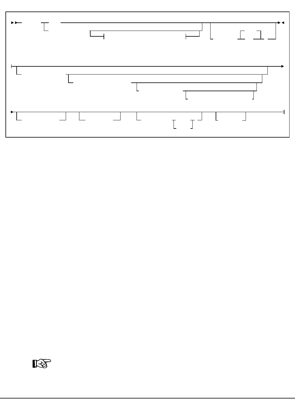
202 VM/HSC 6.0 System Programmer’s Guide
1st ed., 6/30/04 - 312579601
Syntax
Utility Name
AUDIt
specifies that an audit operation is to be performed.
Parameters
ALL
specifies that the total library is to be audited.
APPly
(YES)
specifies that the Audit operation ejects cartridges with duplicate VOLSERs,
unreadable or illegal external media labels, and/or new cartridges unreadable
external labels, and performs corrective actions to the control data set to reflect
the physical contents of storage cells. YES is the default.
(NO)
specifies that a discrepancy listing is produced, and the control data set is not
updated.
ACS
specifies that only a particular ACS in the library is to be audited.
(acs-id)
The one or two digit hexadecimal ACS identifier.
Note: If the ACS parameter is specified with no LSM parameters, the audit is
performed on all LSMs in the ACS at the same time (multitasking). This is the same
as running the AUDIT utility with the ALL parameter. To audit only certain LSMs
within an ACS, you must code the LSM parameter with the LSM or list of LSMs.
AUDIt
Optional Parameters
Optional Parameters:
ACS(acs-id)
ALL
APPLy
(
NO
)
YES
LSM(lsm-list)
PANel(panel-list)
ROW(row-list)
COLumn(column-list)
CAP(cap-id)DIAGScan( )
ONLYEMPTYCel
ALSO
INTRANs
Audit

Chapter 4. Utility Functions 203
1st ed., 6/30/04 - 312579601
LSM
optionally specifies that only certain LSMs within the specified ACS are to be
audited.
(lsm-list)
An lsm-list can be a single LSMid or a list of LSMids. An LSMid (lsm-id) is
made up of the ACSid (hexadecimal 00-FF) and the LSM number (hexadecimal
00-17) separated by a colon (:). An LSM range is not allowed. If a list is
specified, the elements must be separated by blanks or commas, and the entire
list enclosed in parentheses.
PANel
optionally specifies that only certain panels within an LSM are to be audited.
(panel-list)
panel-list may be a single panel or a list of panels. Panel ranges are not allowed.
If a list is specified, the elements must be separated by blanks or commas, and
the entire list enclosed in parentheses.
Refer to the appropriate ACS hardware document for information about LSM
outer and inner wall panel layouts.
Note: If this parameter is specified, the LSM parameter may contain only one
LSM number.
A panel-list element is a one or two digit decimal number.
• For 4410 and 9310 LSMs, valid panel entries are 0 through 11 (outer LSM
wall panels) and 12 through 19 (inner wall panels).
• For 9360 (WolfCreek) LSMs, valid panel entries are 0 through 4.
• For 9740 (TimberWolf) LSMs, valid panel entries are 0 through 3.
• For SL8500 (StreamLine) libraries, valid panel entries are:
- base library — 2-10
- with one expansion panel — 2-18 (expansion panel is 8-15)
- with two expansion panels — 2-26 (expansion panels are 8-23)
- with three expansion panels — 2-34 (expansion panels are 8-31).
Audit

204 VM/HSC 6.0 System Programmer’s Guide
1st ed., 6/30/04 - 312579601
ROW
optionally specifies that only certain rows within the specified LSM panel are to be
audited.
(row-list)
row-list may be a single row or a list of rows. Ranges are not allowed. If a list is
specified, the elements must be separated by blanks or commas, and the entire
list enclosed in parentheses.
If this parameter is specified, the LSM and PANel parameters may contain only
one element.
A row-list element is a one or two digit decimal number.
• For 4410 and 9310 LSMs, valid row entries are 0 through 14 (0 indicates
the top row and 14 indicates the bottom row).
• For 9360 (WolfCreek) LSMs, rows 0 through 41 can be specified with the
exception of panel 1, which contains only four usable cells (rows 35
through 38).
• For 9740 LSMs, valid row entries are 0 through 41 on panels 0, 2, and 3;
and 36 through 41 on panel 1.
• For SL8500 libraries, valid row entries are:
- 0-26 on a standard panel
- 0-12 on a short panel (panels 2-4, 6-7)
- 6-12 on a PTP panel (panel 5)
Notes:
1. On 9740s, column 3 on panel 2 allows row entries only on rows 28
through 41.
2. On 9740s, the cells on panel 3 are optional.
COLumn
optionally specifies that only certain columns (cells) within an LSM panel row are to
be audited.
(column-list)
column-list may be a single column, or a list of columns. Ranges are not
allowed. If a list is specified, the elements must be separated by blanks or
commas, and the entire list enclosed in parentheses.
If this parameter is specified, the LSM, PANel, and ROW parameters may
contain only one element.
A column-list element is a one or two digit decimal number.
Audit

Chapter 4. Utility Functions 205
1st ed., 6/30/04 - 312579601
• For 4410 and 9310 LSMs, valid column entries are 0 though 23, left to
right, for outside wall panel columns. Inner wall panels are numbered 0
through 19, right to left.
• For 9360 (WolfCreek) LSMs, columns 0 through 5 can be specified.
• For 9740 LSMs, valid column entries are 0 through 3 for panels 0, 2, and 3
(if the optional cells are present); 0 through 2 for panel 1.
• For SL8500 libraries, valid column entries are 0 through 1 for each panel
type.
CAP
CAP optionally specifies a particular Cartridge Access Port to be used for any
required cartridge ejections during the Audit operation.
(cap-id)
The Cartridge Access Port identifier. The format for cap-id is AA:LL:CC where
AA is the ACS number (hexadecimal 00-FF), LL is the LSM number
(hexadecimal 00-17), and CC is the CAP number.
Allowable values for CC are:
00
• For 4410 and 9310 LSMs, standard 21-cell CAP or the right-hand 40-cell
enhanced CAP
• For 9360 LSMs, the 20-cell WolfCreek CAP
• For 9740 LSMs, fixed rack 14-cell or 10-cell removable magazine CAP
• For SL8500 libraries, the CAP consists of 3, 13-cell removable magazines.
Note: 000 is also an allowable entry for this CAP type.
01
• For 4410 and 9310 LSMs, left-hand 40-cell enhanced CAP
• For 9360 LSMs, the 30-cell WolfCreek optional CAP
• For SL8500 libraries, this is an optional CAP consisting of 3, 13-cell
removable magazines.
02
priority CAP (PCAP) for a 4410 or 9310 LSM enhanced CAP or for a
9360 LSM CAP.
03
standard fixed rack 14-cell CAP or the 10-cell removable magazine. The
LMU recognizes the configuration when the ACS or LSM is varied online.
Audit
206 VM/HSC 6.0 System Programmer’s Guide
1st ed., 6/30/04 - 312579601
Note: If a CAP is not specified, a CAP in the identified ACS is selected based
on the CAPPref operator command (refer to the ‘‘CAP Preference (CAPPref)
Command and Control Statement’’ in the HSC Operator’s Guide).
Multi-ACS audits cannot specify the CAP parameter. A CAP is chosen for each ACS
based upon CAP preference values.
EMPTYCel
optionally specifies that only empty cells are to be audited. This parameter can be
used in combination with all other AUDIt parameters except
DIAGScan(ONLY).
The main benefit provided by auditing only empty cells is reducing the time required
to run an audit.
Note: StorageTek does not recommend running an empty cell audit on an SL8500
library because the time to run the audit will not be substantially reduced.
Typically, users will want to specify this parameter when:
• they have entered an LSM and placed new cartridges in empty cells, or
• they need to correct cartridge location information for library volumes that have
been manually moved to empty cells.
In either case, if APPLy(YES) is specified, the CDS is updated to reflect that these
cells are no longer empty.
Caution: In some cases, running an empty cell only audit may compromise the
accuracy of the audit.
DIAGScan
optionally specifies that diagnostic cells are to be scanned. The HSC scans these cells
one at a time and displays the contents of each cell in the AUDIt utility report.
Notes:
1. DIAGScan is mutually exclusive with the ROW and COLumn parameters.
It can be used in combination with all other AUDIt parameters.
2. Cartridge movement between diagnostic cells and regular storage or CAP cells
is not supported by the LMU, so diagnostic cell contents can only be reported.
ONLY
specifies that only diagnostic cells should be scanned. This parameter cannot
be specified in combination with the EMPTYCel parameter.
ALSO
specifies that diagnostic cells should also be scanned along with the normal
AUDIt utility operations.
Audit
Chapter 4. Utility Functions 207
1st ed., 6/30/04 - 312579601
INTRANs
optionally specifies that in-transit cartridges in an LSM are to be processed. All
in-transit cartridges, except those identified in the note below, are read and ejected as
part of an AUDIt utility operation.
Notes:
1. INTRANs is mutually exclusive with the APPLY(NO) parameter. It can be
used in combination with all other AUDIt parameters.
2. Only the first two cells (columns 0 and 1) in a 9310 playground are accessible
to an in-transit audit. Cartridges in other cell positions in a 9310 playground
(columns 2 through 5) cannot be ejected by an in-transit operation.
3. 9740 diagnostic cells cannot be scanned by an audit.
JCL Requirements
The following definitions apply to Audit utility JCL:
SLSPRINT
output messages from the utility program.
SLSIN
input to the utility in the form of control cards.
Invoking the Audit Utility
The easiest way to run utilities is to execute the ACS UTIL exec by entering the following
command:
EXEC ACS UTIL AUDIT
Execution of the statement results in the ACSUTIL SLKJCL file:
ACSUTIL SLKJCL File
To execute the utility:
1. Delete the lines in the template that are not required, or leave the comment indicator
(*) in column one.
2. Remove the comment indicator from the desired lines.
/JOB jobname SLUADMIN
/PARM MIXED
/FILe SLSPRINT DEV PRNT CLASS A
/FILE SLSIN *
* AUDIT ALL APPLY (YES)
* AUDIT ACS(acsid) LSM(lsm-list) PANEL(panel-list) CAP(capid) -
* ROW(row-list) COLUMN(col-list) APPLY(YES)
Audit

208 VM/HSC 6.0 System Programmer’s Guide
1st ed., 6/30/04 - 312579601
3. Specify values for the desired parameters.
4. Delete the parameters that are not desired.
5. Enter the command ‘‘FILE.’’
The job file is then submitted to the ACS service machine for execution.
JCL Examples
The following example shows JCL for auditing an entire library (all ACSs).
JCL for Audit of Entire Library (all ACSs)
The following example shows JCL for a selective audit of a single ACS and two LSMs.
The CAPid where the cartridges are to be ejected is also specified.
JCL for Selective Audit (1 ACS, 2 LSMs, with CAPid)
The following example shows JCL for a selective audit specifying a panel-list and
producing a discrepancy list if duplicate VOLSERs or unreadable/illegal cartridge labels
are encountered.
JCL for Selective Audit (with panel-list and discrepancy list)
/JOB jobname SLUADMIN
/PARM MIXED
/FILE SLSPRINT DEV PRNT CLASS A
/FILE SLSIN *
AUDIT ALL
/JOB jobname SLUADMIN
/PARM MIXED
/FILE SLSPRINT DEV PRNT CLASS A
/FILE SLSIN *
AUDIT ACS(01) LSM(01,02) CAP(00)
/JOB jobname SLUADMIN
/PARM MIXED
/FILE SLSPRINT DEV PRNT CLASS A
/FILE SLSIN *
AUDIT ACS(01) LSM(04) PANEL(6,12) APPLY(NO)
Audit

Chapter 4. Utility Functions 209
1st ed., 6/30/04 - 312579601
JCL for Selective Audit of Empty Cells
JCL for Selective Audit of Diagnostic Cells Only
JCL for Selective Audit that Includes Diagnostic Cells
Output Description
Output resulting from the execution of the Audit utility includes:
• a listing of input commands with appropriate messages when syntax errors occur
• messages associated with error conditions resulting from an unsuccessful attempt to
execute audit processing
• messages indicating anomalies observed and/or actions occurring during processing
(see Figure 10 on page 210)
• updated and validated library control data set with respect to the library elements that
have been audited (if APPly(YES) is specified).
//JOBAUDT job (account),programmer
//S1 EXEC PGM=SLUADMIN,PARM=MIXED
//SLSPRINT DD SYSOUT=A
//SLSIN DD *
AUDIT ACS(00) LSM(01) EMPTYCELL
/*
//
/JOBAUDT job (account),programmer
//S1 EXEC PGM=SLUADMIN,PARM=MIXED
//SLSPRINT DD SYSOUT=A
//SLSIN DD *
AUDIT ACS(00) LSM(02) DIAGSCAN(ONLY)
/*
//
/JOBAUDT job (account),programmer
//S1 EXEC PGM=SLUADMIN,PARM=MIXED
//SLSPRINT DD SYSOUT=A
//SLSIN DD *
AUDIT ACS(00) LSM(02) PANEL(6,7,8) DIAGSCAN(ALSO)
/*
//
Audit

210 VM/HSC 6.0 System Programmer’s Guide
1st ed., 6/30/04 - 312579601
SLUADMIN (n.n.n) StorageTek Automated Cartridge System Utility PAGE 0001
TIME hh:mm:ss Control Card Image Listing DATE yyyy-mm-dd
AUDIT ACS(00) LSM(11)
SLUADMIN (n.n.n) StorageTek Automated Cartridge System Utility PAGE 0002
TIME hh:mm:ss Audit Utility DATE yyyy-mm-dd
-SLS0231I Audit phase 1 (Registration) completed
-
SLS2200I Warning: Volume MVC005 Media-type compare failed between VOLATTR and cartridge label
-SLS0232I Audit phase 2 (Volumes Check) completed
-
SLS0199I Volume CLN504 in cell 00:11:00:02:00 is in control data set at cell 00:11:00:00:00
SLS0199I Volume CLN505 in cell 00:11:00:02:05 is in control data set at cell 00:11:00:00:05
SLS0238I Audit scan for LSMid 00:11, panel 0 has completed
SLS0238I Audit scan for LSMid 00:11, panel 1 has completed
SLS0238I Audit scan for LSMid 00:11, panel 2 has completed
SLS0238I Audit scan for LSMid 00:11, panel 3 has completed
SLS0238I Audit scan for LSMid 00:11, panel 4 has completed
SLS0238I Audit scan for LSMid 00:11, panel 5 has completed
SLS0238I Audit scan for LSMid 00:11, panel 6 has completed
SLS0238I Audit scan for LSMid 00:11, panel 7 has completed
SLS0238I Audit scan for LSMid 00:11, panel 8 has completed
SLS0238I Audit scan for LSMid 00:11, panel 9 has completed
SLS0238I Audit scan for LSMid 00:11, panel 10 has completed
SLS0238I Audit scan for LSMid 00:11, panel 11 has completed
SLS0238I Audit scan for LSMid 00:11, panel 12 has completed
SLS0200I Volume Y20114 in cell 00:11:13:02:05 is not in control database
SLS0238I Audit scan for LSMid 00:11, panel 13 has completed
SLS0238I Audit scan for LSMid 00:11, panel 14 has completed
SLS0238I Audit scan for LSMid 00:11, panel 15 has completed
SLS0238I Audit scan for LSMid 00:11, panel 16 has completed
SLS0200I Volume Y20133 in cell 00:11:17:02:07 is not in control database
SLS0238I Audit scan for LSMid 00:11, panel 17 has completed
SLS0238I Audit scan for LSMid 00:11, panel 18 has completed
SLS0238I Audit scan for LSMid 00:11, panel 19 has completed
SLS0239I Audit scan for panels in LSMid 00:11 has terminated
-SLS0233I Audit phase 3 (Cell Scan) completed
SLS0213I Volume Y00133 not located by Audit
SLS0213I Volume Y00114 not located by Audit
-SLS0234I Audit phase 4 (Finish) completed
SLS0155I Condition code for utility function is 4
Figure 10. AUDIt Utility Sample Output
Audit

Chapter 4. Utility Functions 211
1st ed., 6/30/04 - 312579601
Backup Utility
The BACKup utility allows you to back up the library control data set. The control data set
is the single most important resource required in the operation of the HSC. Various
controls and services are available to keep the control data set intact and to enable you to
recover the data set from a total failure. Features such as shadowing, journaling, backup,
and restore, are all intended to provide for the integrity of the control data set. A library
can have the following control data sets:
•Primary control data set. Every installation must have this data set. It contains the
inventory of all cartridges in the library, the library configuration, information about
library hardware and resource ownership across multiple processors, and serves as a
vehicle of communication between the HSCs running on multiple processors.
•Secondary control data set. This optional data set is a duplicate copy of the primary
control data set.
•Standby control data set. This data set is optional. It is a formatted control data set
with only one valid record, the Database Heartbeat (DHB). It is highly recommended
that a standby control data set be created and initialized in your installation. This
database is used primarily for control data set recovery.
Prerequisites
The BACKup utility can be executed with or without functioning library host software.
Note: Backup to tape is not supported.
Reasons for Running the BACKup Utility
The following items justify running the BACKup utility:
• regularly scheduled backups can be run to prevent inadvertent loss of information
• the primary and/or secondary copy of the control data set for your library has been
deleted or corrupted
• in a multi-processor environment, due to a CDS switch on one processor, the primary
and secondary CDS might run independently and become unsynchronized.
In such a situation, you must determine which of two non-identical control data sets
is the correct copy; the BACKup utility assists you in recovery.
• to choose the CDS with the most current updates if a database mismatch is detected.
Refer to “When CDS Copies Are Split Among Hosts After an Error” on page 213 for the
procedure to recover control data sets in remote-linked libraries.
Backup

212 VM/HSC 6.0 System Programmer’s Guide
1st ed., 6/30/04 - 312579601
How the BACKup Utility Functions
The BACKup utility performs extensive error checking on CDS records, as well as
comparison checking between primary and secondary copies of the CDS.
Note: In order to run a back up correctly, all data sets currently defined to the HSC should
be specified. This ensures that proper CDS selection and reservation occurs.
If both copies of the data set are available and an I/O error occurs during the analysis
phase of backup, the utility attempts to continue backup on the other copy unless the CDS
keyword specifies the CDS that contains the error. If the CDS keyword specifies the
control data set containing the error, the utility terminates.
Depending upon the option that you select with the keyword OPTion,
• a straight copy is made
• a detailed block analysis is performed
• a restart of the utility is performed.
Copy data sets are made for use as analysis data sets to limit the hardware reserve placed
on the control data set to an absolute minimum. Depending upon options selected, analysis
of data blocks can be performed and block information modified before the data is written
to the backup data set (SLSBKUP).
A return code of eight (RC=8) can be expected if shadowing (a secondary CDS) is enabled
and the secondary /FILE statement is not provided. A backup of the primary control data
set will not be taken.
If for any reason, a return code of eight (RC=8) occurs, the utility may be able to be
restarted (refer to “How to Restart Backup” on page 224).
The RESTore utility works in conjunction with BACKup by formatting the discrepancy
blocks into control card statements and outputting them to the SLSAUDIT data set. When
the HSC is reactivated after a backup and restore, the discrepancy control statements are
input to the SLUADMIN program and AUDIt, UNSCratch, and UNSElect are performed
to resolve discrepancies.
Refer to “Restore Utility” on page 276 for detailed information on the RESTore utility.
Backup

Chapter 4. Utility Functions 213
1st ed., 6/30/04 - 312579601
Backup Procedure
Backup of the control data set may be performed using conventions for specifying the
secondary control data set and with copy data sets to enable block analysis, if desired. The
following procedure describes steps for performing backups (see “JCL Examples” on page
247 for each step).
1. If OPTion(Analyze) is specified, allocate the SLSCOPY1 and SLSCOPY2 data sets.
This step is not necessary if you specify OPTion(Copy). These data sets must be the
size of the current control data set.
2. Allocate the SLSBKUP data set. It should be slightly larger than the control data sets.
The size depends upon the number of discrepancies found. However, a recommended
size is five percent larger than the current control data set.
3. Run the BACKup utility. If backup options requiring copy data sets are specified, the
control data set’s volume is placed in a reserve state only long enough for the data to
be copied to the SLSCOPYn data sets. The resident-host cannot access either control
data set except for backup processing.
The library control data set is backed-up to the user-specified DASD data set. If
journaling is enabled, all specified journals are reset when the backup is completed.
Note: Up to 99 journals can be specified per run.
Finally, the control data set is returned to a state where it can support normal library
processing. If Analyze is specified, the SLSCOPYn data sets are processed using
unreserved READs; otherwise, the utility ends.
4. If SLSCOPYn data sets are used and a return code of less than RC=8 (i.e., backup
successful) is achieved, these data sets may be deleted or reused when the backup is
restarted due to a failure.
When CDS Copies Are Split Among Hosts After an Error
Special precautions should be taken for running BACKup and RESTore when
local/remote-linked libraries run control data sets independent of each other. In this
situation, the primary and secondary control data sets are being updated by the HSC on
their respective sides of the link. If remote communication is lost, the two control data sets
become unsynchronized.
Precautions also should be followed when the link connecting the local and remote
libraries is disrupted.
Special considerations while the link is down include:
• Keep enters and ejects of cartridges to a minimum. This practice reduces the number
of AUDIT statements produced.
• Enter MNTD Float(OFf). This generates more pass-thrus, but less AUDIT
statements.
• Enter MNTD SCRDISM(CURRENT) to avoid cartridge movement.
Backup
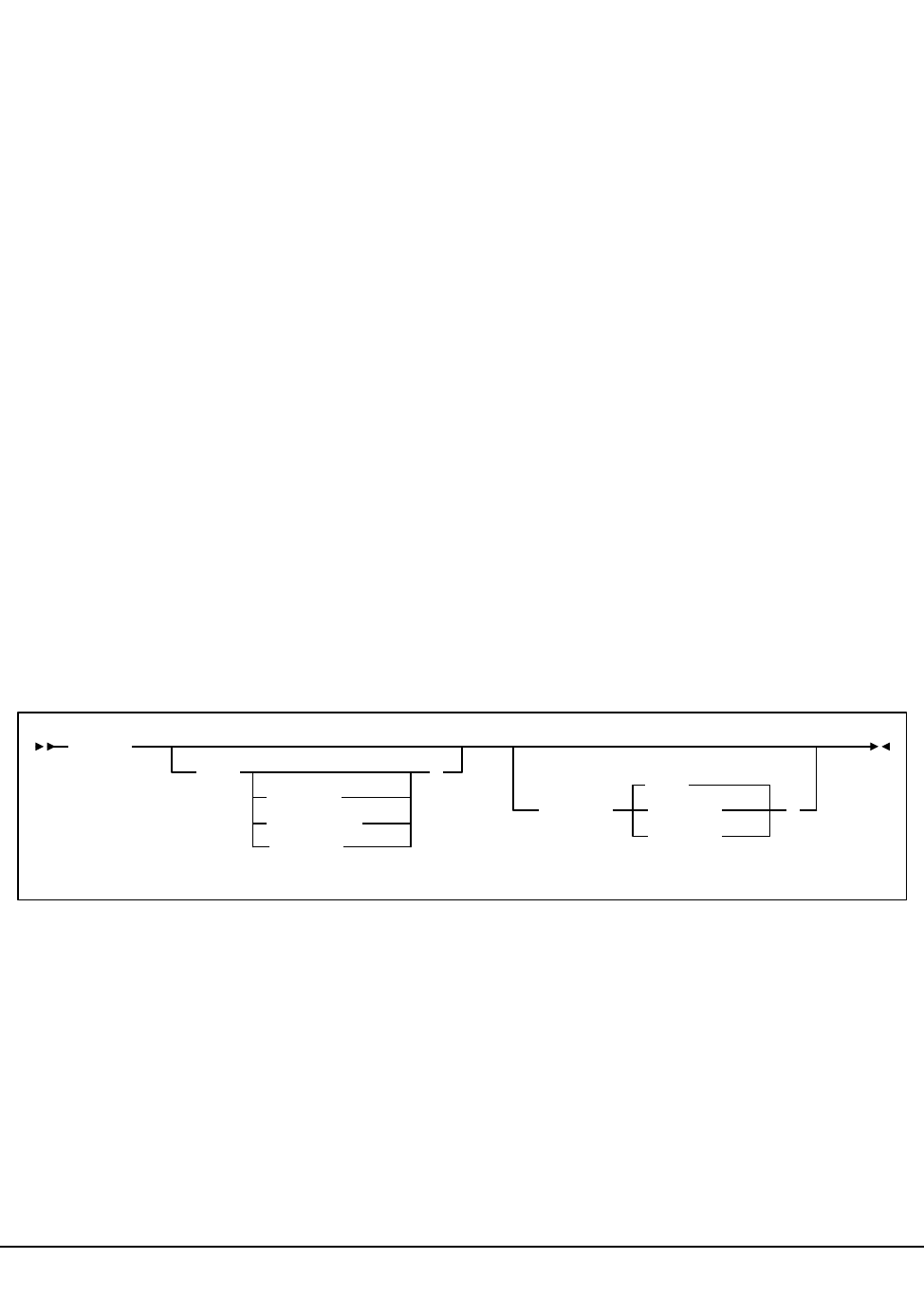
214 VM/HSC 6.0 System Programmer’s Guide
1st ed., 6/30/04 - 312579601
• Avoid running the SET utility.
• Avoid running the Scratch Update and Scratch Redistribution functions during this
time.
• Take all HSCs down prior to the link being restored.
Special considerations after the link is restored include:
• Avoid restoring CDS copies from backups taken while the link is down. If a restore
of the CDS(s) is necessary only on one side of the link, make sure that only the
CDS(s) on that side is restored.
Do this by including only /FILE statements for the data sets on the side of the link to
be restored. Do not restore all CDS copies from a backup taken while the link is
down.
• After the link is restored, ALL HSCs should remain down for backup/restore.
• Run BACKup. OPTion(Analyze) must be used.
• If you know which CDS has had the most processing occur after the link was
disrupted, use the CDS keyword to select that CDS for backup.
• Once backup is completed, restore the control data sets. Do not apply journals.
• Reinitialize the HSCs.
• When the ACSs are available, start the SLUADMIN program using the SLSAUDIT
data set from the restore as input.
Syntax
Utility Name
BACKup
specifies that a backup operation is to be performed.
Parameters
CDS
optionally, specifies that a backup is to be run on a control data set. If CDS is not
specified, the BACKup utility backs up the CDS containing the most updates.
BACKup
CDS(
Primary
Secondary
STandby
)
OPTion(
Restart
Analyze
Copy
)
Backup

Chapter 4. Utility Functions 215
1st ed., 6/30/04 - 312579601
For regularly scheduled backups of HSC control data sets, do not specify the CDS
keyword when each CDS copy is not being backed up individually in the same time
frame. The reason for not specifying the CDS keyword is that a CDS switch(es) may
have taken place.
(Primary)
specifies that the primary control data set is to be copied to the SLSBKUP data
set.
(Secondary)
specifies that the secondary control data set is to be copied to the SLSBKUP
data set.
(STandby)
specifies that the standby control data set is to be copied to the SLSBKUP data
set.
Notes:
1. The CDS parameter specifies the CDS currently in that position. For example,
if the primary CDS is disabled and the secondary CDS is running as the
primary, specify Primary (not Secondary) to back up the secondary CDS.
2. Using the CDS parameter is especially useful for libraries operating through a
remote link, such as channel extenders. Should the link drop and the primary
CDS and the secondary CDS complete processing separately, you may bypass
the programmatic algorithm that normally determines the control data set to be
backed up. If you know which data set (primary or secondary) had the most
cartridge processing, then you can select that data set to be processed by the
utility.
OPTion
optionally, allows you to select one of three backup options.
(Copy)
if this parameter is specified, NO block analysis is performed. The backup is
taken from one of the control data sets. This function is a straight copy to the
SLSBKUP data set. /FILE SLSCOPYx statements are not required in the JCL
for this option.
OPTion(Copy) is the default and should be used or defaulted to for
regularly scheduled backups of the HSC control data set.
OPTion(Copy) determines which copy of the CDS is the most current and
copies that CDS copy to the SLSBKUP data set. This dynamic determination of
the current primary CDS is disabled if the CDS keyword is specified.
(Analyze)
this option allows detailed analysis of individual blocks to occur. A reserve is
held against the control data set until the SLSCOPY data sets are made and the
journals are reset. An analysis is made and discrepancies are output to a
Backup

216 VM/HSC 6.0 System Programmer’s Guide
1st ed., 6/30/04 - 312579601
summary report and to the SLSBKUP data set. Refer to Figure 11 on page 222
to see a sample discrepancy report. An errant and in-transit destination report,
followed by a block processing report, also is produced in this case. Figure 11
shows these reports.
Note: The VOLSERs and cell locations that are discrepant are sorted into an
incremental stack to reduce the amount of robotic movement.
Up to 10,000 discrepancies can be recorded for the Scratch and Select
discrepancy types; 96,000 discrepancies or one ACS can be recorded for the
Audit discrepancy type. Once these limits have been reached, discrepancy
saving is discontinued. Discrepancies saved prior to reaching the limits are
retained and output.
If you specify this option, normally SLSCNTL represents the current primary
data set; SLSCNTL2 specifies the current secondary data set. However, if you
are recovering from a link down or multi-host switch situation, SLSCNTL
should remain the current primary CDS on one side of the link while
SLSCNTL2 should be specified as the current primary CDS on the other side of
the link. If you are sure which two CDSs should be compared, do not specify
SLSSTBY.
Upon restore, the discrepancy blocks are used to generate UNSCratch,
UNSElect, and AUDIt statements to the SLSAUDIT data set.
Note: It is better to use OPTion(Copy) for regularly scheduled backups of the
HSC CDS. OPTion(Analyze) is designed to backup the CDSs when there may
be discrepancies between copies of the CDS.
(Restart)
specifies to bypass the initial copy of the control data sets to the SLSCOPY data
sets. This option is used when a system outage or job failure has occurred after
the control data sets have been copied to the SLSCOPY data sets. Analysis of
the previous backup run-time report indicates the successful copies.
If you have journals, the report should be inspected to determine if the journals
were successfully reset. If they have not been reset, a backup should be taken
again to obtain the most current control data sets prior to doing the journal
resets.
If the journals have been reset, OPTion(Restart) should be used to obtain the
information from the SLSCOPY data sets.
Backup

Chapter 4. Utility Functions 217
1st ed., 6/30/04 - 312579601
JCL Requirements
The following definitions apply to the BACKup utility JCL:
SLSPRINT
the message output data set.
SLSCNTL
the primary control data set. This statement must be provided.
SLSCNTL2
the secondary control data set. If a secondary CDS exists, it should be specified so
that if a switch occurs and the secondary data set is now active, the CDSs can be
reordered to maintain database integrity.
SLSBKUP
the created backup data set.
SLSSTBY
the standby data set. If a standby exists, it should be specified so that if a switch
occurs and the standby data set is now active, the CDSs can be reordered to maintain
database integrity.
SLSCOPY1
the data set to which the primary control data set (specified by the /FILE SLSCNTL
statement) is copied. This statement is not required when you specify OPTion(Copy).
SLSCOPY2
the data set to which the secondary control data set (specified by the /FILE
SLSCNTL2 statement) is copied. This statement is not required when you specify
OPTion(Copy).
SLSJRNnn
if journaling is enabled, these statements define the library journal data sets. All
journals must be specified. Up to 99 journals can be specified. Allowable values for
nn are decimal 01 to 99, but numbers cannot be skipped.
SLSIN
input to the utility in the form of control statement card images.
Backup

218 VM/HSC 6.0 System Programmer’s Guide
1st ed., 6/30/04 - 312579601
Invoking the BACKup Utility
The easiest way to run utilities is to execute the ACS UTIL exec by entering the following
command:
EXEC ACS UTIL BACKUP
Execution of the statement results in the ACSUTIL SLKJCL file:
ACSUTIL SLKJCL File
To execute the utility:
1. Delete the lines in the template that are not required, or leave the comment indicator
(*) in column one.
2. Remove the comment indicator from the desired lines.
3. Specify values for the desired parameters.
4. Delete the parameters that are not desired.
5. Enter the command ‘‘FILE.’’
The job file is then submitted to the ACS service machine for execution.
/JOB jobname SLUADMIN
/PARM MIXED
/FILE SLSPRINT DEV PRNT CLASS A
/FILE SLSCNTL DEV <vaddr> DSN <dsname>
/FILE SLSCNTL2 DEV <vaddr> DSN <dsname>
/FILE SLSBKUP DEV <vaddr> DSN <dsname>
/FILE SLSCOPY1 DEV <vaddr> DSN <dsname>
/FILE SLSCOPY2 DEV <vaddr> DSN <dsname>
/FILE SLSJRN01 DEV <vaddr> DSN <dsname>
/FILE SLSJRN02 DEV <vaddr> DSN <dsname>
/FILE SLSIN *
* BACKUP OPT(COPY)
Backup

Chapter 4. Utility Functions 219
1st ed., 6/30/04 - 312579601
JCL Examples
Various examples showing JCL for running the BACKup utility are presented. Select an
appropriate example matching the control statement conventions that you have used for
specifying data sets.
JCL for Running Backup
The first example shows JCL for backup with the primary, secondary, and standby control
data sets, copy data sets (SLSCOPY1 and SLSCOPY2), and journals. The JCL to perform
a backup contains the following statements:
Run Backup Utility
JCL for Running a Copy Backup
The following examples show JCL for running a straight copy backup of the control data
set.
This example specifies BACKup utilizing OPTion(Copy) with shadowing (a secondary
CDS) and journaling enabled. The SLSCNTL statement identifies the primary control data
set. Backup is processed with journals. If the /FILE SLSCNTL2 statement is not provided,
a return code of four (RC=4) is generated, and a backup of the primary is taken.
JCL for Backup of Primary or Secondary CDS with Journals
/JOB jobname SLUADMIN
/PARM MIXED
/FILE SLSCNTL DEV vaddr DSN primary.set.name
/FILE SLSCNTL2 DEV vaddr DSN secondary.set.name
/FILE SLSSTBY DEV vaddr DSN standby.set.name
/FILE SLSBKUP DEV vaddr DSN backup.set.name
/FILE SLSJRN#1 DEV vaddr DSN journal1.set.name
/FILE SLSJRN#2 DEV vaddr DSN journal2.set.name
/FILE SLSCOPY1 DEV vaddr DSN copy1.set.name
/FILE SLSCOPY2 DEV vaddr DSN copy2.set.name
/FILE SLSPRINT DEV PRNT CLASS A
/FILE SLSIN *
BACKUP OPTION(ANALYZE) CDS(PRIMARY)
/JOB jobname SLUADMIN
/PARM MIXED
/FILE SLSBKUP DEV vaddr DSN backup.set.name
/FILE SLSCNTL DEV vaddr DSN primary.set.name
/FILE SLSCNTL2 DEV vaddr DSN secondary.set.name
/FILE SLSJRN#1 DEV vaddr DSN journal1.set.name
/FILE SLSJRN#2 DEV vaddr DSN journal2.set.name
/FILE SLSPRINT DEV PRNT CLASS A
/FILE SLSIN *
BACKUP OPTION(COPY)
Backup
220 VM/HSC 6.0 System Programmer’s Guide
1st ed., 6/30/04 - 312579601
This example specifies BACKup with the SLSCNTL statement to identify the primary
control data set. Backup is processed without a secondary control data set and journals.
JCL for Backup of the Primary CDS without Secondary and Journals
Output Description
Output resulting from the execution of the BACKup utility includes:
• the following data sets:
- backup of the library control data set
- copies of the primary and secondary control data sets
- reset of the control data set journals.
• a listing of input commands with appropriate messages when syntax errors occur
• messages associated with backup processing
Note: These messages may include error conditions.
• an ‘‘Errant and In-transit Location Report’’ (refer to Figure 11 on page 222)
Note: This report is normal. In-transit and possibly errant VOLSERs are normal
when the HSC is active.
• a ‘‘Block Processing Report’’ and a “Block Record Element Discrepancy Report,”
which may include reports of mismatches between the primary and secondary CDS
(refer to Figure 11 on page 222)
Note: Unselect cards may be generated during a good backup of a primary and
secondary CDS that match.
/JOB jobname SLUADMIN
/PARM MIXED
/FILE SLSBKUP DEV vaddr DSN backup.set.name
/FILE SLSCNTL DEV vaddr DSN primary.set.name
/FILE SLSPRINT DEV PRNT CLASS A
/FILE SLSIN *
BACKUP
Backup

Chapter 4. Utility Functions 221
1st ed., 6/30/04 - 312579601
• a condition code from backup processing:
0no errors and no SLUADMIN control cards generated
4warning MESSAGES – Backup successful
8a system failure occurred. Restart or rerun backup.
Backup

222 VM/HSC 6.0 System Programmer’s Guide
1st ed., 6/30/04 - 312579601
SLUADMIN (n.n.n) STORAGETEK AUTOMATED CARTRIDGE SYSTEM UTILITY PAGE 0001
TIME hh:mm:ss CONTROL CARD IMAGE LISTING DATE yyyy-mm-dd
BACKUP OPTION(ANALYZE)
SLUADMIN (n.n.n) STORAGETEK AUTOMATED CARTRIDGE SYSTEM UTILITY PAGE 0002
TIME hh:mm:ss BACKUP UTILITY DATE yyyy-mm-dd
SLS1315I SPRC.@793665.V6L.DBASEPRM WAS SELECTED AS THE PRIMARY CONTROL DATA SET
SLS1212I JCL HAS BEEN VERIFIED FOR THE BACKUP UTILITY
SLS1216I SLSCNTL WAS SELECTED AS THE CONTROL DATA SET TO OUTPUT
SLS1215I SLSCNTL WAS SUCCESSFULLY COPIED TO SLSCOPY1
SLUADMIN (n.n.n) STORAGETEK AUTOMATED CARTRIDGE SYSTEM UTILITY PAGE 0003
TIME hh:mm:ss BACKUP UTILITY DATE yyyy-mm-dd
BLOCK PROCESSING REPORT
SLS1210I PROCESSING HAS STARTED FOR THE DHB BLOCK
SLS1211I PROCESSING COMPLETE FOR THE DHB BLOCK
SLS1210I PROCESSING HAS STARTED FOR THE DPV BLOCK
SLS1211I PROCESSING COMPLETE FOR THE DPV BLOCK
SLS1210I PROCESSING HAS STARTED FOR THE DDIR BLOCK
SLS1211I PROCESSING COMPLETE FOR THE DDIR BLOCK
SLS1210I PROCESSING HAS STARTED FOR THE DALM BLOCK
SLS1211I PROCESSING COMPLETE FOR THE DALM BLOCK
SLS1210I PROCESSING HAS STARTED FOR THE LSM BLOCK
SLS1211I PROCESSING COMPLETE FOR THE LSM BLOCK
SLS1210I PROCESSING HAS STARTED FOR THE CAP BLOCK
SLS1211I PROCESSING COMPLETE FOR THE CAP BLOCK
SLS1210I PROCESSING HAS STARTED FOR THE VSLB BLOCK
SLS1211I PROCESSING COMPLETE FOR THE VSLB BLOCK
SLS1210I PROCESSING HAS STARTED FOR THE DPTR BLOCK
SLS1211I PROCESSING COMPLETE FOR THE DPTR BLOCK
SLS1210I PROCESSING HAS STARTED FOR THE VSLB BLOCK
SLS1211I PROCESSING COMPLETE FOR THE VSLB BLOCK
SLS1210I PROCESSING HAS STARTED FOR THE DCX BLOCK
SLS1211I PROCESSING COMPLETE FOR THE DCX BLOCK
SLS1210I PROCESSING HAS STARTED FOR THE DPTR BLOCK
SLS1211I PROCESSING COMPLETE FOR THE DPTR BLOCK
SLS1210I PROCESSING HAS STARTED FOR THE DCX BLOCK
SLS1211I PROCESSING COMPLETE FOR THE DCX BLOCK
SLS1210I PROCESSING HAS STARTED FOR THE VCAM BLOCK
SLS1211I PROCESSING COMPLETE FOR THE VCAM BLOCK
•
•
•
SLS1210I PROCESSING HAS STARTED FOR THE ACS BLOCK
SLS1211I PROCESSING COMPLETE FOR THE ACS BLOCK
SLS1210I PROCESSING HAS STARTED FOR THE DRV BLOCK
SLS1211I PROCESSING COMPLETE FOR THE DRV BLOCK
SLS1210I PROCESSING HAS STARTED FOR THE GBL BLOCK
SLS1211I PROCESSING COMPLETE FOR THE GBL BLOCK
Figure 11. BACKup Utility Sample Output
(1 of 2)
Backup

Chapter 4. Utility Functions 223
1st ed., 6/30/04 - 312579601
SLUADMIN (n.n.n) STORAGETEK AUTOMATED CARTRIDGE SYSTEM UTILITY PAGE 0004
TIME hh:mm:ss BACKUP UTILITY DATE yyyy-mm-dd
SLS1210I PROCESSING HAS STARTED FOR THE DITA BLOCK
SLS1211I PROCESSING COMPLETE FOR THE DITA BLOCK
SLS1210I PROCESSING HAS STARTED FOR THE DITR BLOCK
SLS1211I PROCESSING COMPLETE FOR THE DITR BLOCK
SLS1210I PROCESSING HAS STARTED FOR THE DPTR BLOCK
SLS1211I PROCESSING COMPLETE FOR THE DPTR BLOCK
•
•
•
SLS1210I PROCESSING HAS STARTED FOR THE DES BLOCK
SLS1211I PROCESSING COMPLETE FOR THE DES BLOCK
SLS1210I PROCESSING HAS STARTED FOR THE DPTR BLOCK
SLS1211I PROCESSING COMPLETE FOR THE DPTR BLOCK
SLS1210I PROCESSING HAS STARTED FOR THE DES BLOCK
SLS1211I PROCESSING COMPLETE FOR THE DES BLOCK
SLS1210I PROCESSING HAS STARTED FOR THE FREE BLOCK
SLS1211I PROCESSING COMPLETE FOR THE FREE BLOCK
SLS1215I SLSCOPY1 WAS SUCCESSFULLY COPIED TO SLSBKUP
SLUADMIN (n.n.n) STORAGETEK AUTOMATED CARTRIDGE SYSTEM UTILITY PAGE 0005
TIME hh:mm:ss BACKUP UTILITY DATE yyyy-mm-dd
ERRANT AND INTRANSIT LOCATION REPORT
|-- VOLSER --| |-- SOURCE LOCATION --| |-- DESTINATION LOCATION --|
A0040C CELL 00:01:08:00:00 DRIVEID 00:00:09:00
Y00130 CELL 00:11:14:00:00 DRIVEID 00:11:10:01
SLUADMIN (n.n.n) STORAGETEK AUTOMATED CARTRIDGE SYSTEM UTILITY PAGE 0006
TIME hh:mm:ss BACKUP UTILITY DATE yyyy-mm-dd
BLOCK RECORD ELEMENT DISCREPANCY REPORT
|--ACTION--| |-DATATYPE-| |-----------------DETAILED ELEMENT DISCREPANCY INFORMATION-----------------|
UNSELECT VOLSER (A0040C,Y00130)
UNSCRATCH VOLSER NO VOLSER DISCREPANCIES FOUND.
AUDIT CELL (00:01:08:00:00,00:11:14:00:00)
SLS1213I DISCREPANCY BLOCKS HAVE BEEN GENERATED
SLS0155I CONDITION CODE FOR UTILITY FUNCTION IS 4
Figure 11. BACKup Utility Sample Output
(2 of 2)
Backup

224 VM/HSC 6.0 System Programmer’s Guide
1st ed., 6/30/04 - 312579601
How to Restart Backup
After executing the BACKup utility, if a system failure or any other circumstance occurs
that causes a return code of eight (RC=8), the BACKup utility can be restarted as long as
criteria described in “Parameters” on page 214 for OPTion(Restart) is true.
Related Utilities
The RESTore utility complements the BACKup utility. If a restore is required, it should be
performed immediately after a CDS failure. Refer to “Restore Utility” on page 276 for
detailed information about the Restore utility.
Backup

Chapter 4. Utility Functions 225
1st ed., 6/30/04 - 312579601
Database Decompile (LIBGEN) Utility
The Database Decompile utility provides a way to generate LIBGEN macro statements
from an existing library control data set.
Prerequisites
The utility runs under the control of the SLUADMIN program and does not require the
HSC to be running.
Reasons for Running the Database Decompile Utility
The following are possible reasons for running the Database Decompile utility to restore
the LIBGEN for a library:
• The LIBGEN for your library has been deleted, lost, or corrupted; you want to
re-create the file to match your library configuration.
• The SET utility is used to change the library configuration stored in the CDS;
consequently, the original LIBGEN no longer matches the CDS.
How the Database Decompile Utility Functions
The utility performs the following processing to create the LIBGEN from the existing
control data set.
• opens the existing control data set and an output data set to hold the recreated
LIBGEN data set
• reads the control data set into buffers and determines validity of the existing control
data set
• locates host IDs generated for the library
• extracts values from the control data set corresponding with LIBGEN macro
parameters and re-creates the output of each LIBGEN macro. The re-creation follows
the same required order as in LIBGEN generation (see ‘‘LIBGEN Macros’’ in the
HSC Installation Guide for information about library generation).
During the re-creation processing, various reads, calculations, and copies are
performed.
• If errors are encountered, appropriate messages are displayed (see the HSC Messages
and Codes Guide for explanations of error messages)
• Upon completion, the output LIBGEN deck is ready for configuration changes and
reassembly for the SLICREAT program (see ‘‘Executing the SLICREAT Program’’
in the HSC Installation Guide for information on data set initialization using the
SLICREAT program).
Database Decompile
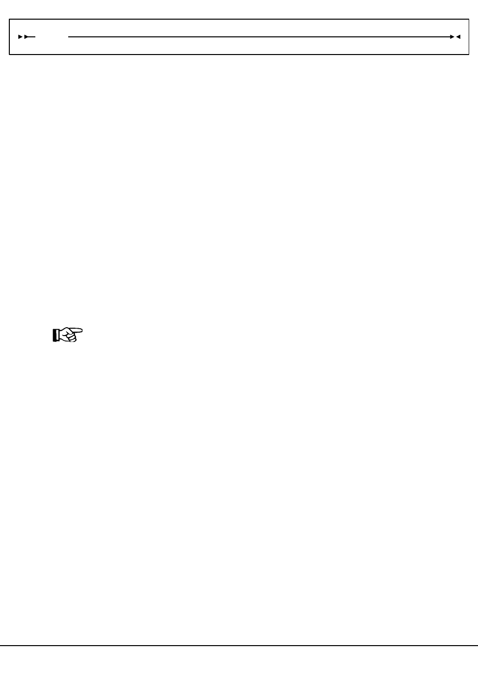
226 VM/HSC 6.0 System Programmer’s Guide
1st ed., 6/30/04 - 312579601
Syntax
Utility Name
LIBGEN
specifies that database processing is to be performed and invokes the SLUDBMAP
module. SLUDBMAP creates a complete HSC LIBGEN from an existing control
data set.
Parameters
None.
JCL Requirements
The following definitions apply to the LIBGEN utility JCL:
SLSPRINT
output messages from the utility program.
SLSCNTL
the primary control data set. This statement is required.
Note: SLSCNTL should be the copy of the CDS currently selected as the primary
CDS. Two ways to determine the identity of the primary CDS are:
• issue the Display CDS command, and look at PRIVOL
• run the BACKup OPTion(Analyze) utility and note the ‘‘ddname was selected
as the control dataset to output’’ line in the output report (ddname is the name of
the current primary CDS).
SLSLIBGN
the output data set to accommodate the LIBGEN created by the utility. The data set
has these characteristics: LRECL=80, fixed-blocked format (multiple of 80). This is
a PUNCH file. This statement is required.
SLSIN
input to the utility in the form of control cards.
LIBGEN
Database Decompile

Chapter 4. Utility Functions 227
1st ed., 6/30/04 - 312579601
Invoking the Database Decompile Utility
The easiest way to run utilities is to execute the ACS UTIL exec by entering the following
command:
EXEC ACS UTIL LIBGEN
Execution of the statement results in the ACSUTIL SLKJCL file:
ACSUTIL SLKJCL File
To execute the utility:
1. Delete the lines in the template that are not required, or leave the comment indicator
(*) in column one.
2. Remove the comment indicator from the desired lines.
3. Specify values for the desired parameters.
4. Delete the parameters that are not desired.
5. Enter the command ‘‘FILE.’’
The job file is then submitted to the ACS service machine for execution.
JCL Example
The following example shows JCL for creating a LIBGEN from the existing control data
set.
JCL for Database Decompile
/JOB jobname SLUADMIN
/PARM MIXED
/FILE SLSPRINT DEV PRNT CLASS A
/FILE SLSCNTL DEV <500> DSN <dsname>
/FILE SLSLIBGN DEV PNCH CLASS A
/FILE SLSIN *
* LIBGEN
/JOB jobname SLUADMIN
/FILE SLSCNTL DEV vaddr DSN dsname
/FILE SLSLIBGN DEV PNCH CLASS A
/FILE SLSPRINT DEV PRNT CLASS A
/FILE SLSIN *
* LIBGEN
Database Decompile

228 VM/HSC 6.0 System Programmer’s Guide
1st ed., 6/30/04 - 312579601
Output Description
Outputs resulting from the execution of the Database Decompile utility include:
• a valid LIBGEN file matching the existing control data set. The output file has the
following characteristics:
- All station and drive addresses are 4-character addresses.
- In cases where multiple parameters point to the same label statement, the utility
duplicates the statement with a unique label and points each parameter to a
different, although identical statement.
- Labels generated in the output LIBGEN are listed in Table 12.
- If an EJect password exists, it is not displayed. Instead, the following line is
displayed: EJCTPAS=????????
• messages associated with error conditions resulting from an unsuccessful execution
of the utility.
Refer to Figure 12 on page 229 for an example of output from the utility.
Table 12. Label Descriptions for Devices in Output LIBGEN
Device Label Description
ACS ACSaa aa is the sequential hexadecimal ACSid value
(00 through FF), beginning with zero.
LSM LSMaall aa is the ACSid, and ll is the sequential
hexadecimal LSMid value (00 through 17),
beginning with zero.
STATION STaah aa is the ACSid, and h is the sequential
hexadecimal host index value (0 through F),
beginning with zero.
PANEL Paallpp aa is the ACSid, ll is the LSMid, and pp is the
sequential decimal panel number (0 through 10).
DRIVE Daallpph aa is the ACSid, ll is the LSMid, pp is the
decimal panel number, and h is the hexadecimal
host index value, beginning with zero.
Database Decompile

Chapter 4. Utility Functions 229
1st ed., 6/30/04 - 312579601
***********************************************************************
* THIS IS A LIBGEN OF A SINGLE ACS WITH 24 POWDERHORN LSMS ATTACHED *
* TO 16 HOSTS. EACH LSM HAS A SINGLE DRIVE PANEL WITH 4 DRIVES *
***********************************************************************
*
LIBGEN SLIRCVRY TCHNIQE=SHADOW
*
SLILIBRY SMF=245, X
ACSLIST=ACSLIST, X
HOSTID=(EC17,MVSI,ECC4,ECCX,MVSE,MVSF,MVSS, X
EC21,ECCL,ECCY,MVSC,MVSJ,ECC6,ECCI, X
SLK1,SLK2), X
NNLBDRV=(,,,,,,,,,,,,,,,), X
DELDISP=SCRTCH, X
MAJNAME=ENQTHIS, X
CLNPRFX=CLN, X
COMPRFX=#, X
SCRLABL=SL
*
*
ACSLIST SLIALIST ACS00
*
ACS00 SLIACS ACSDRV=(TACS0,TACS0,TACS0,TACS0,TACS0,TACS0, X
TACS0,TACS0,TACS0,TACS0,TACS0,TACS0,TACS0, X
TACS0,TACS0,TACS0), X
STATION=(ST000,ST000,,ST000,ST000,ST000,ST000,ST000, X
ST000,ST000,ST000,ST000,ST000,ST000,ST000,ST000), X
LSM=(LSM0000,LSM0001,LSM0002,LSM0003,LSM0004,LSM0005, X
LSM0006,LSM0007,LSM0008,LSM0009,LSM000A,LSM000B, X
LSM000C,LSM000D,LSM000E,LSM000F,LSM0010,LSM0011, X
LSM0012,LSM0013,LSM0014,LSM0015,LSM0016,LSM0017)
*
ST000 SLISTATN ADDRESS=(00CC)
*
*----------------
*
LSM0000 SLILSM PASTHRU=((8,M),(6,M)), X
ADJACNT=(LSM0002,LSM0001), X
DRIVE=(2), X
DRVELST=(P000000), X
TYPE=9310, X
DOOR=ECAP
*
P000000 SLIDLIST HOSTDRV=(D0000000,D0000000,D0000000,D0000000, X
D0000000,D0000000,D0000000,D0000000,D0000000, X
D0000000,D0000000,D0000000,D0000000,D0000000, X
D0000000,D0000000)
*
D0000000 SLIDRIVS ADDRESS=(0A00,0A01,0A02,0A03)
*
*----------------
*
LSM0001 SLILSM PASTHRU=((6,S),(4,M),(2,M)), X
ADJACNT=(LSM0000,LSM0002,LSM0003), X
DRIVE=(10), X
DRVELST=(P000001), X
TYPE=9310, X
DOOR=ECAP
*
P000001 SLIDLIST HOSTDRV=(D0000001,D0000001,D0000001,D0000001, X
D0000001,D0000001,D0000001,D0000001,D0000001, X
D0000001,D0000001,D0000001,D0000001,D0000001, X
D0000001,D0000001)
*
D0000001 SLIDRIVS ADDRESS=(0A04,0A05,0A06,0A07)
*
*----------------
Figure 12. Database Decompile Utility Sample Output
(1 of 7)
Database Decompile

230 VM/HSC 6.0 System Programmer’s Guide
1st ed., 6/30/04 - 312579601
*
LSM0002 SLILSM PASTHRU=((2,S),(4,S),(6,M),(8,M)), X
ADJACNT=(LSM0000,LSM0001,LSM0003,LSM0004), X
DRIVE=(10), X
DRVELST=(P00002), X
TYPE=9310, X
DOOR=ECAP
*
P000002 SLIDLIST HOSTDRV=(D0000002,D0000002,D0000002,D0000002, X
D0000002,D0000002,D0000002,D0000002,D0000002, X
D0000002,D0000002,D0000002,D0000002,D0000002, X
D0000002,D0000002)
*
D0000002 SLIDRIVS ADDRESS=(0A08,0A09,0A0A,0A0B)
*
*----------------
*
LSM0003 SLILSM PASTHRU=((8,S),(6,S),(4,M),(2,M)), X
ADJACNT=(LSM0001,LSM0002,LSM0004,LSM0005), X
DRIVE=(10), X
DRVELST=(P000003), X
TYPE=9310, X
DOOR=ECAP
*
P000003 SLIDLIST HOSTDRV=(D0000003,D0000003,D0000003,D0000003, X
D0000003,D0000003,D0000003,D0000003,D0000003, X
D0000003,D0000003,D0000003,D0000003,D0000003, X
D0000003,D0000003)
*
D0000003 SLIDRIVS ADDRESS=(0A0C,0A0D,0A0E,0A0F)
*
*----------------
*
LSM00004 SLILSM PASTHRU=((2,S),(4,S),(6,M),(8,M)), X
ADJACNT=(LSM0002,LSM0003,LSM0005,LSM0006), X
DRIVE=(10), X
DRVELST=(P000004), X
TYPE=9310, X
DOOR=ECAP
*
P000004 SLIDLIST HOSTDRV=(D0000004,D0000004,D0000004,D0000004, X
D0000004,D0000004,D0000004,D0000004,D0000004, X
D0000004,D0000004,D0000004,D0000004,D0000004, X
D0000004,D0000004)
*
D0000004 SLIDRIVS ADDRESS=(0A10,0A11,0A12,0A13)
*
*----------------
*
LSM0005 SLILSM PASTHRU=((8,S),(6,S),(4,M),(2,M)), X
ADJACNT=(LSM0003,LSM0004,LSM0006,LSM0007), X
DRIVE=(10), X
DRVELST=(P000005), X
TYPE=9310, X
DOOR=ECAP
*
P000005 SLIDLIST HOSTDRV=(D0000005,D0000005,D0000005,D0000005, X
D0000005,D0000005,D0000005,D0000005,D0000005, X
D0000005,D0000005,D0000005,D0000005,D0000005, X
D0000005,D0000005)
*
D0000005 SLIDRIVS ADDRESS=(0A14,0A15,0A16,0A17)
*
*----------------
Figure 12. Database Decompile Utility Sample Output
(2 of 7)
Database Decompile

Chapter 4. Utility Functions 231
1st ed., 6/30/04 - 312579601
*
LSM0006 SLILSM PASTHRU=((2,S),(4,S),(6,M),(8,M)), X
ADJACNT=(LSM0004,LSM0005,LSM0007,LSM0008), X
DRIVE=(10), X
DRVELST=(P000006), X
TYPE=9310, X
DOOR=ECAP
*
P000006 SLIDLIST HOSTDRV=(D0000006,D0000006,D0000006,D0000006, X
D0000006,D0000006,D0000006,D0000006,D0000006, X
D0000006,D0000006,D0000006,D0000006,D0000006, X
D0000006,D0000006)
*
D0000006 SLIDRIVS ADDRESS=(0A18,0A19,0A1A,0A1B)
*
*----------------
*
LSM0007 SLILSM PASTHRU=((8,S),(6,S),(4,M),(2,M)), X
ADJACNT=(LSM0005,LSM0006,LSM0008,LSM0009), X
DRIVE=(10), X
DRVELST=(P000007), X
TYPE=9310, X
DOOR=ECAP
*
P000007 SLIDLIST HOSTDRV=(D0000007,D0000007,D0000007,D0000007, X
D0000007,D0000007,D0000007,D0000007,D0000007, X
D0000007,D0000007,D0000007,D0000007,D0000007, X
D0000007,D0000007)
*
D0000007 SLIDRIVS ADDRESS=(0A1C,0A1D,0A1E,0A1F)
*
*----------------
*
LSM0008 SLILSM PASTHRU=((2,S),(4,S),(6,M),(8,M)), X
ADJACNT=(LSM0006,LSM0007,LSM0009,LSM000A), X
DRIVE=(10), X
DRVELST=(P000008), X
TYPE=9310, X
DOOR=ECAP
*
P000008 SLIDLIST HOSTDRV=(D0000008,D0000008,D0000008,D0000008, X
D0000008,D0000008,D0000008,D0000008,D0000008, X
D0000008,D0000008,D0000008,D0000008,D0000008, X
D0000008,D0000008)
*
D0000008 SLIDRIVS ADDRESS=(0A20,0A21,0A22,0A23)
*
*----------------
*
LSM0009 SLILSM PASTHRU=((8,S),(6,S),(4,M),(2,M)), X
ADJACNT=(LSM0007,LSM0008,LSM000A,LSM000B), X
DRIVE=(10), X
DRVELST=(P000009), X
TYPE=9310, X
DOOR=ECAP
*
P000009 SLIDLIST HOSTDRV=(D0000009,D0000009,D0000009,D0000009, X
D0000009,D0000009,D0000009,D0000009,D0000009, X
D0000009,D0000009,D0000009,D0000009,D0000009, X
D0000009,D0000009)
*
D0000009 SLIDRIVS ADDRESS=(0A24,0A25,0A26,0A27)
*
*----------------
Figure 12. Database Decompile Utility Sample Output
(3 of 7)
Database Decompile

232 VM/HSC 6.0 System Programmer’s Guide
1st ed., 6/30/04 - 312579601
*
LSM000A SLILSM PASTHRU=((2,S),(4,S),(6,M),(8,M)), X
ADJACNT=(LSM0008,LSM0009,LSM000B,LSM000C), X
DRIVE=(10), X
DRVELST=(P00000A), X
TYPE=9310, X
DOOR=ECAP
*
P00000A SLIDLIST HOSTDRV=(D000000A,D000000A,D000000A,D000000A, X
D000000A,D000000A,D000000A,D000000A,D000000A, X
D000000A,D000000A,D000000A,D000000A,D000000A, X
D000000A,D000000A)
*
D000000A SLIDRIVS ADDRESS=(0A28,0A29,0A2A,0A2B)
*
*----------------
*
LSM000B SLILSM PASTHRU=((8,S),(6,S),(4,M),(2,M)), X
ADJACNT=(LSM0009,LSM000A,LSM000C,LSM000D), X
DRIVE=(10), X
DRVELST=(P00000B), X
TYPE=9310, X
DOOR=ECAP
*
P00000B SLIDLIST HOSTDRV=(D000000B,D000000B,D000000B,D000000B, X
D000000B,D000000B,D000000B,D000000B,D000000B, X
D000000B,D000000B,D000000B,D000000B,D000000B, X
D000000B,D000000B)
*
D000000B SLIDRIVS ADDRESS=(0A2C,0A2D,0A2E,0A2F)
*
*----------------
*
LSM000C SLILSM PASTHRU=((2,S),(4,S),(6,M),(8,M)), X
ADJACNT=(LSM000A,LSM000B,LSM000D,LSM000E), X
DRIVE=(10), X
DRVELST=(P00000C), X
TYPE=9310, X
DOOR=ECAP
*
P00000C SLIDLIST HOSTDRV=(D000000C,D000000C,D000000C,D000000C, X
D000000C,D000000C,D000000C,D000000C,D000000C, X
D000000C,D000000C,D000000C,D000000C,D000000C, X
D000000C,D000000C)
*
D000000C SLIDRIVS ADDRESS=(0A30,0A31,0A32,0A33)
*
*----------------
*
LSM000D SLILSM PASTHRU=((8,S),(6,S),(4,M),(2,M)), X
ADJACNT=(LSM000B,LSM000C,LSM000E,LSM000F), X
DRIVE=(10), X
DRVELST=(P00000D), X
TYPE=9310, X
DOOR=ECAP
*
P00000D SLIDLIST HOSTDRV=(D000000D,D000000D,D000000D,D000000D, X
D000000D,D000000D,D000000D,D000000D,D000000D, X
D000000D,D000000D,D000000D,D000000D,D000000D, X
D000000D,D000000D)
*
D000000D SLIDRIVS ADDRESS=(0A34,0A35,0A36,0A37)
*
*----------------
Figure 12. Database Decompile Utility Sample Output
(4 of 7)
Database Decompile

Chapter 4. Utility Functions 233
1st ed., 6/30/04 - 312579601
*
LSM000E SLILSM PASTHRU=((2,S),(4,S),(6,M),(8,M)), X
ADJACNT=(LSM000C,LSM000D,LSM000F,LSM0010), X
DRIVE=(10), X
DRVELST=(P00000E), X
TYPE=9310, X
DOOR=ECAP
*
P00000E SLIDLIST HOSTDRV=(D000000E,D000000E,D000000E,D000000E, X
D000000E,D000000E,D000000E,D000000E,D000000E, X
D000000E,D000000E,D000000E,D000000E,D000000E, X
D000000E,D000000E)
*
D000000E SLIDRIVS ADDRESS=(0A38,0A39,0A3A,0A3B)
*
*----------------*
LSM000F SLILSM PASTHRU=((2,S),(4,S),(6,M),(8,M)), X
ADJACNT=(LSM000D,LSM000E,LSM0010,LSM0011), X
DRIVE=(10), X
DRVELST=(P00000F), X
TYPE=9310, X
DOOR=ECAP
*
P00000F SLIDLIST HOSTDRV=(D000000F,D000000F,D000000F,D000000E, X
D000000F,D000000F,D000000F,D000000F,D000000F, X
D000000F,D000000F,D000000F,D000000F,D000000F, X
D000000F,D000000F)
*
D000000F SLIDRIVS ADDRESS=(0A3C,0A3D,0A3E,0A3F)
*
*----------------
*
LSM0010 SLILSM PASTHRU=((2,S),(4,S),(6,M),(8,M)), X
ADJACNT=(LSM000E,LSM000F,LSM0011,LSM0012), X
DRIVE=(10), X
DRVELST=(P000010), X
TYPE=9310, X
DOOR=ECAP
*
P000010 SLIDLIST HOSTDRV=(D0000010,D0000010,D0000010,D0000010, X
D0000010,D0000010,D0000010,D0000010,D0000010, X
D0000010,D0000010,D0000010,D0000010,D0000010, X
D0000010,D0000010)
*
D0000010 SLIDRIVS ADDRESS=(0A40,0A41,0A42,0A43)
*
*----------------
*
LSM0011 SLILSM PASTHRU=((2,S),(4,S),(6,M),(8,M)), X
ADJACNT=(LSM000F,LSM0010,LSM0012,LSM0013), X
DRIVE=(10), X
DRVELST=(P000011), X
TYPE=9310, X
DOOR=ECAP
*
P000011 SLIDLIST HOSTDRV=(D0000011,D0000011,D0000011,D0000011, X
D0000011,D0000011,D0000011,D0000011,D0000011, X
D0000011,D0000011,D0000011,D0000011,D0000011, X
D0000011,D0000011)
*
D0000011 SLIDRIVS ADDRESS=(0A44,0A45,0A46,0A47)
*
*----------------
Figure 12. Database Decompile Utility Sample Output
(5 of 7)
Database Decompile

234 VM/HSC 6.0 System Programmer’s Guide
1st ed., 6/30/04 - 312579601
*
LSM0012 SLILSM PASTHRU=((2,S),(4,S),(6,M),(8,M)), X
ADJACNT=(LSM0010,LSM0011,LSM0013,LSM0014), X
DRIVE=(10), X
DRVELST=(P000012), X
TYPE=9310, X
DOOR=ECAP
*
P000012 SLIDLIST HOSTDRV=(D0000012,D0000012,D0000012,D0000012, X
D0000012,D0000012,D0000012,D0000012,D0000012, X
D0000012,D0000012,D0000012,D0000012,D0000012, X
D0000012,D0000012)
*
D0000012 SLIDRIVS ADDRESS=(0A48,0A49,0A4A,0A4B)
*
*----------------
*
LSM0013 SLILSM PASTHRU=((2,S),(4,S),(6,M),(8,M)), X
ADJACNT=(LSM0011,LSM0012,LSM0014,LSM0015), X
DRIVE=(10), X
DRVELST=(P000013), X
TYPE=9310, X
DOOR=ECAP
*
P000013 SLIDLIST HOSTDRV=(D0000013,D0000013,D0000013,D0000013, X
D0000013,D0000013,D0000013,D0000013,D0000013, X
D0000013,D0000013,D0000013,D0000013,D0000013, X
D0000013,D0000013)
*
D0000013 SLIDRIVS ADDRESS=(0A4C,0A4D,0A4E,0A4F)
*
*----------------
*
LSM0014 SLILSM PASTHRU=((2,S),(4,S),(6,M),(8,M)), X
ADJACNT=(LSM0012,LSM0013,LSM0015,LSM0016), X
DRIVE=(10), X
DRVELST=(P000014), X
TYPE=9310, X
DOOR=ECAP
*
P000014 SLIDLIST HOSTDRV=(D0000014,D0000014,D0000014,D0000014, X
D0000014,D0000014,D0000014,D0000014,D0000014, X
D0000014,D0000014,D0000014,D0000014,D0000014, X
D0000014,D0000014)
*
D0000014 SLIDRIVS ADDRESS=(0A50,0A51,0A52,0A53)
*
*----------------
*
LSM0015 SLILSM PASTHRU=((2,S),(4,S),(6,M),(8,M)), X
ADJACNT=(LSM0013,LSM0014,LSM0016,LSM0017), X
DRIVE=(10), X
DRVELST=(P000015), X
TYPE=9310, X
DOOR=ECAP
*
P000015 SLIDLIST HOSTDRV=(D0000015,D0000015,D0000015,D0000015, X
D0000015,D0000015,D0000015,D0000015,D0000015, X
D0000015,D0000015,D0000015,D0000015,D0000015, X
D0000015,D0000015)
*
D0000015 SLIDRIVS ADDRESS=(0A54,0A55,0A56,0A57)
*
*----------------
Figure 12. Database Decompile Utility Sample Output
(6 of 7)
Database Decompile

Chapter 4. Utility Functions 235
1st ed., 6/30/04 - 312579601
*
LSM0016 SLILSM PASTHRU=((8,S),(6,S),(4,M)), X
ADJACNT=(LSM0014,LSM0015,LSM0016), X
DRIVE=(10), X
DRVELST=(P000016), X
TYPE=9310, X
DOOR=ECAP
*
P000016 SLIDLIST HOSTDRV=(D0000016,D0000016,D0000016,D0000016, X
D0000016,D0000016,D0000016,D0000016,D0000016, X
D0000016,D0000016,D0000016,D0000016,D0000016, X
D0000016,D0000016)
*
D0000016 SLIDRIVS ADDRESS=(0A58,0A59,0A5A,0A5B)
*
*----------------
*
LSM0017 SLILSM PASTHRU=((2,S),(4,S)), X
ADJACNT=(LSM0015,LSM0016), X
DRIVE=(10), X
DRVELST=(P000017), X
TYPE=9310, X
DOOR=ECAP
*
P000017 SLIDLIST HOSTDRV=(D0000017,D0000017,D0000017,D0000017, X
D0000017,D0000017,D0000017,D0000017,D0000017, X
D0000017,D0000017,D0000017,D0000017,D0000017, X
D0000017,D0000017)
*
D0000017 SLIDRIVS ADDRESS=(0A5C,0A5D,0A5E,0A5F)
*
*----------------
*
*
*
SLIENDGN ,
Figure 12. Database Decompile Utility Sample Output
(7 of 7)
Database Decompile

236 VM/HSC 6.0 System Programmer’s Guide
1st ed., 6/30/04 - 312579601
Directory Rebuild Utility
The Directory Rebuild utility provides a means to rebuild the database directory for all
defined CDS copies.
Prerequisites
The stand-alone Directory Rebuild utility:
• runs under the control of the SLUADMIN utilities program
• may be run while the CDS-related HSCs are STOPped
• must be run using all CDS copies as input.
Reasons for Running the Directory Rebuild Utility
The major purpose of the Directory Rebuild utility is to repair a corrupted CDS database
directory when the HSC is not active. Normally, the HSC corrects errors automatically.
How the Directory Rebuild Utility Functions
The utility performs the following processing to rebuild the database directory:
• opens the control data sets specified by the SLSCNTL, SLSCNTL2, and SLSSTBY
DD statements
• locates invalid pointers, directory entries, and recovery data
• rewrites corrected blocks to all CDS copies.
Syntax
Utility Name
DIRBLD
specifies that directory rebuild processing is to be performed and invokes the
SLUDRDIR module.
Parameters
None.
JCL Requirements
The following definitions apply to the DIRBLD utility JCL:
SLSPRINT
output messages from the utility program.
DIRBLD
Directory Rebuild

Chapter 4. Utility Functions 237
1st ed., 6/30/04 - 312579601
SLSCNTL, SLSCNTL2, SLSSTBY
SLSCNTL is the primary CDS, SLSCNTL2 is the secondary CDS, and SLSSTBY is
the standby CDS from which the directory is rebuilt. This statement is required for
each CDS that has been defined.
SLSIN
input to the utility in the form of control cards.
Invoking the Database Decompile Utility
The easiest way to run utilities is to execute the ACS UTIL exec by entering the following
command:
EXEC ACS UTIL DIRBLD
Execution of the statement results in the ACSUTIL SLKJCL file:
ACSUTIL SLKJCL File
To execute the utility:
1. Delete the lines in the template that are not required, or leave the comment indicator
(*) in column one.
2. Remove the comment indicator from the desired lines.
3. Specify values for the desired parameters.
4. Delete the parameters that are not desired.
5. Enter the command ‘‘FILE.’’
The job file is then submitted to the ACS service machine for execution.
/JOB jobname SLUADMIN
/PARM MIXED
/FILE SLSCNTL DEV <vaddr> DSN <dsname>
/FILE SLSPRINT DEV PRNT CLASS A
/FILE SLSIN *
* DIRBLD
Directory Rebuild

238 VM/HSC 6.0 System Programmer’s Guide
1st ed., 6/30/04 - 312579601
JCL Example
The following example shows JCL for Directory Rebuild execution.
JCL for Directory Rebuild
Output Description
Output resulting from the execution of the Directory Rebuild utility includes:
• a listing of input commands with appropriate messages when syntax errors occur
• messages associated with error conditions resulting from an unsuccessful attempt to
execute DIRBLD processing
• an updated CDS with corrected pointer and directory information
• a condition code indicating successful or unsuccessful CDS update.
/JOB jobname SLUADMIN
/PARM MIXED
/FILE SLSCNTL DEV 501 DSN SLS.DBASE
/FILE SLSPRINT DEV PRNT CLASS A
/FILE SLSIN *
* DIRBLD
Directory Rebuild
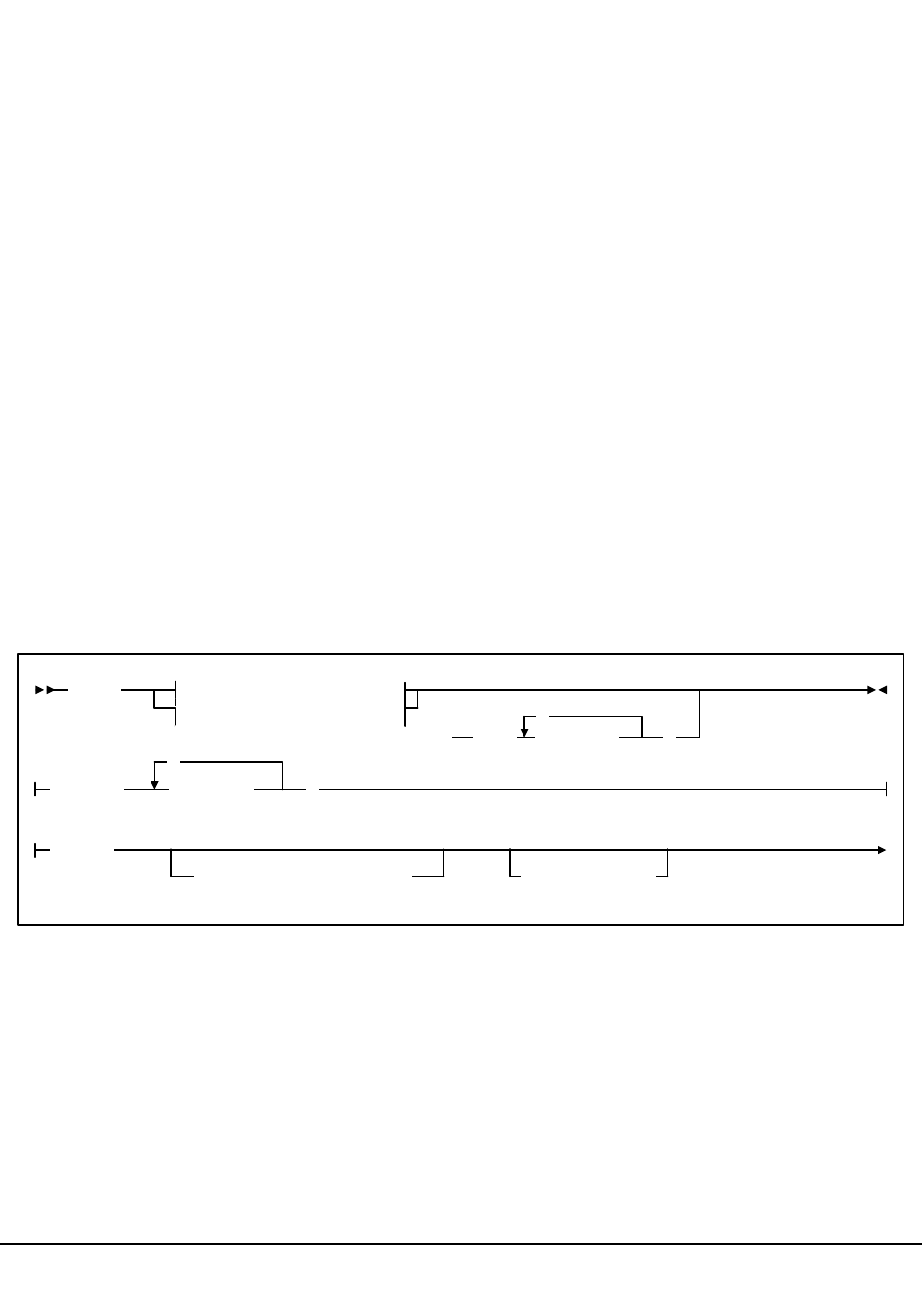
Chapter 4. Utility Functions 239
1st ed., 6/30/04 - 312579601
Eject Cartridge Utility
The EJECt Cartridge utility permits you to remove one or more cartridges from an ACS in
a batch mode. For the automated ejection of cartridges, the EJECt Cartridge utility takes
advantage of the Cartridge Access Port (CAP) in an LSM.
The control statement allows you to designate a single CAP, a specific CAP, or a list of
specific CAPs. Specifying one or more CAPs limits cartridge ejection to those CAPs.
Ejections in a multiple ACS configuration may specify CAPs in each ACS if volumes
reside in each ACS. If a CAP list is not provided, the utility selects the highest priority
CAP available for each ACS (refer to the ‘‘CAP Preference (CAPPref) Command and
Control Statement’’ in the HSC Operator’s Guide).
You may elect to submit multiple EJECt Cartridge utility requests, each of which may
specify a particular CAP. If you elect to specify a CAP in a multi-ACS configuration, then
the list of volumes must reside within the CAP ACS.
Multiple CAPs within one ACS can be allocated to the EJECt utility. Specifying multiple
CAPs in a single EJECt Cartridge utility typically improves performance by reducing
pass-thrus.
If two CAPs are specified in the same LSM, cartridges in that LSM are ejected in
sequential order. This is helpful for vaulting.
Syntax
EJECt Eject Method 1
Eject Method 2
CAP( cap-list )
,
Eject Method 1:
Eject Method 2:
VOLser( vol-list
,
)
SCRTCH
SUBpool(subpool-name)VOLCNT(count)
Eject Cartridge
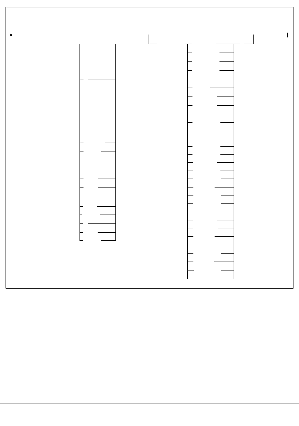
240 VM/HSC 6.0 System Programmer’s Guide
1st ed., 6/30/04 - 312579601
Utility Name
EJECt
specifies that ejection processing is to be performed.
Eject Method 2 (continued):
MEDia( Standard )
CST
MEDIA1
STD
1
3480
ECART
E
ECCST
ETAPE
Long
MEDIA2
3490E
ZCART
Z
DD3A
DD3B
DD3C
STK1R
R
STK2
RECtech( 18track
36Atrack
36Btrack
36Ctrack
DD3
)
STK1R
STK1R34
STK1R35
STK1RA
STK1RA34
STK1RA35
STK1RB
STK1RB34
STK1RB35
STK1
STK2P
STK2P
STK2P34
STK2P35
STK2PA
STK1RAB
STK1RAB4
STK1RAB5
STK1RC
STK1RC34
STK1RC35
STK2PA34
STK2PA35
STK2PB
STK2PB34
STK2PB35
Eject Cartridge

Chapter 4. Utility Functions 241
1st ed., 6/30/04 - 312579601
Parameters
VOLser
specifies that a VOLSER(s) is to be ejected.
(vol-list)
vol-list specifies the list of volumes to be ejected. A vol-list can be a single
VOLSER, a range of VOLSERs or a list of VOLSERs and/or VOLSER ranges
in any combination.
If a list is specified, the elements must be delimited by commas or blanks, and
the entire list enclosed in parentheses. A range of VOLSERs consists of a
starting VOLSER and an ending VOLSER separated by a dash.
SCRTCH
indicates that scratch volumes are to be ejected.
Note: If no CAPs are specified, only scratch tapes in ACS 00 are ejected.
SUBpool
optionally specifies the subpool from which scratch volumes are to be ejected. If
MEDia or RECtech are specified, cartridges are ejected for that media type or
recording technique within the same subpool.
(subpool-name)
subpool-name indicates the name for the subpool.
VOLCNT
optionally specifies that a designated number of scratch volumes are to be ejected.
(count)
count indicates the number of scratch volumes to be ejected.
MEDia
optionally, specifies that scratch cartridges of the desired media are to be ejected.
1. If MEDia is not specified, the next scratch cartridge is selected without regard
to media type if RECtech does not exist. If both MEDia and RECtech are
supplied, they must be compatible.
2. The SL8500 library supports only the T9x40 (9840/T9840B/T9840C and
T9940A/T9940B) media types and recording techniques.
Valid media types are:
Standard
indicates a standard length, 3480 cartridge. It can be used on any longitudinal
drives (4480, 4490, 9490, or 9490EE). Data can be written in 36-track mode on
4490, 9490, or 9490EE transports but cannot be read on an 18-track (4480)
drive. Synonyms for this type of cartridge include:
Eject Cartridge

242 VM/HSC 6.0 System Programmer’s Guide
1st ed., 6/30/04 - 312579601
•CST
•MEDIA1
• STD
•1
• 3480
ECART
indicates a 3490E, extended capacity cartridge. It can be used only on a
36-track drive (4490, 9490, or 9490EE). Synonyms include:
•E
• ECCST
•ETAPE
• Long
•MEDIA2
• 3490E
ZCART
indicates a 3490E, extended capacity cartridge that provides greater storage
capacity than an ECART. It can be used only on a 9490EE drive.
ZCART can be abbreviated as Z.
DD3A, DD3B, DD3C
indicates a helical cartridge. The media indicator in the external label is
encoded with the cartridge type (A, B, or C).
Notes: DD3A, DD3B, or DD3C can be abbreviated to A, B, or C respectively.
Types of helical cartridges, along with their associated media capacities, are:
•A - 10GB
•B - 25GB
• C - 50GB.
Data capacity differences between DD3A, DD3B, and DD3C cartridges are
related to the length of the tape in the cartridge, not to the recording density of
the data.
STK1
indicates any T9840 cartridge.
STK1R
indicates a T9840 20GB data cartridge. The media indicator in the external
label is encoded with the cartridge type (R). STK1R can be abbreviated to R.
Eject Cartridge

Chapter 4. Utility Functions 243
1st ed., 6/30/04 - 312579601
STK2
indicates any T9940 cartridge. This parameter is the default for all T9940A and
T9940B data cartridge types.
STK2P
indicates a T9940 data cartridge. The media indicator in the external label is
encoded with the cartridge type (P).
Note: STK2P can be abbreviated to P.
RECtech
optionally, specifies scratch cartridges of the desired recording technique are to be
ejected. RECtech indicates the method used to record data tracks on the tape surface.
1. If RECtech is not specified, the next scratch cartridge is selected depending on
the media type (if supplied). If neither is supplied, the next scratch cartridge is
selected without taking media type and recording technique into consideration.
If both RECtech and MEDia are supplied, they must be compatible.
2. The SL8500 library supports only the T9x40 (9840/T9840B/T9840C and
T9940A/T9940B) media types and recording techniques.
Valid recording techniques are:
18track
indicates a 4480 transport.
36track
indicates a 4490, 9490, or 9490EE transport (any device that records in 36-track
mode).
36Atrack
indicates a 4490 (Silverton) transport.
36Btrack
indicates a 9490 (Timberline) transport.
36Ctrack
indicates a 9490EE transport.
HELical
indicates a device using helical recording.
DD3
indicates a device using helical recording.
STK1R
indicates a 9840 transport.
Eject Cartridge

244 VM/HSC 6.0 System Programmer’s Guide
1st ed., 6/30/04 - 312579601
STK1R34
indicates a 3490E-image 9840 transport.
STK1R35
indicates a 3590-image 9840 transport.
STK1RA
indicates a 3490E or 3590-image 9840 transport.
STK1RA34
indicates a 3490E-image 9840 transport.
STK1RA35
indicates a 3590-image 9840 transport.
STK1RB
indicates a 3490E or 3590-image T9840B transport.
STK1RB34
indicates a 3490E-image T9840B transport.
STK1RB35
indicates a 3590-image T9840B transport.
STK1RAB
indicates a 3490E or 3590-image T9840A or T9840B transport.
STK1RAB4
indicates a 3490E-image T9840A or T9840B transport.
STK1RAB5
indicates a 3590E-image T9840A or T9840B transport.
STK1RC
indicates a 3490E or 3590-image T9840C transport.
STK1RC34
indicates a 3490-image T9840C transport.
STK1RC35
indicates a 3590-image T9840C transport.
STK2P
indicates any T9940 transport.
STK2P34
indicates a 3490E-image T9940A transport.
STK2P35
indicates a 3590-image T9940A transport.
Eject Cartridge

Chapter 4. Utility Functions 245
1st ed., 6/30/04 - 312579601
STK2PA
indicates a T9940A transport.
STK2PA34
indicates a 3490E-image T9940A transport.
STK2PA35
indicates a 3590-image T9940A transport.
STK2PB
indicates a T9940B transport.
STK2PB34
indicates a 3490E-image T9940B transport.
STK2PB35
indicates a 3590-image T9940B transport.
CAP
specifies which Cartridge Access Port(s) is being used for the operation.
This utility ejects scratch volumes to the specified CAP(s) only. EJECt searches for
scratch volumes only in the LSMs that contain the specified CAP(s).
Note: If a CAP has not been specified, EJECt determines the CAP to use based
upon the CAPPref command setting (refer to ‘‘CAP Preference (CAPPref)
Command and Control Statement’’ in the HSC Operator’s Guide).
If a CAP preference has not been specified, the HSC displays a message and waits
until the user enters a CAPPref value. Pass-thrus can be made to CAPs specified by
CAPPref.
(cap-list)
cap-list identifies the Cartridge Access Port(s). The cap-list requires
explicitly specified CAPids separated by commas. A CAPid range is not
allowed.
If more than one CAPid is specified, the elements must be separated by
blanks or commas, and the entire list must be enclosed in parentheses. If
no CAP is specified, one is chosen in each ACS.
The format for cap-id is AA:LL:CC where AA is the ACS number
(hexadecimal 00-FF), LL is the LSM number (hexadecimal 00-17), and
CC is the CAP number.
Allowable values for CC are:
00
• For 4410 and 9310 LSMs, standard 21-cell CAP or the right-hand 40-cell
enhanced CAP
Eject Cartridge

246 VM/HSC 6.0 System Programmer’s Guide
1st ed., 6/30/04 - 312579601
• For 9360 LSMs, the 20-cell WolfCreek CAP
• For 9740 LSMs, fixed rack 14-cell or 10-cell removable magazine CAP
• For SL8500 libraries, the CAP consists of 3, 13-cell removable magazines.
01
• For 4410 and 9310 LSMs, left-hand 40-cell enhanced CAP
• For 9360 LSMs, the 30-cell WolfCreek optional CAP
• For SL8500 libraries, this is an optional CAP consisting of 3, 13-cell
removable magazines.
02
priority CAP (PCAP) for a 4410 or 9310 LSM enhanced CAP or for a
9360 LSM CAP.
JCL Requirements
The following definitions apply to EJECt Cartridge utility JCL:
SLSPRINT
output messages from the utility program.
SLSIN
input to the utility in the form of control statements.
Invoking the Eject Cartridge Utility
The easiest way to run utilities is to execute the ACS UTIL exec by entering the following
command:
EXEC ACS UTIL EJECT
Execution of the statement results in the ACSUTIL SLKJCL file:
ACSUTIL SLKJCL File
To execute the utility:
1. Delete the lines in the template that are not required, or leave the comment indicator
(*) in column one.
2. Remove the comment indicator from the desired lines.
3. Specify values for the desired parameters.
/JOB jobname SLUADMIN
/PARM MIXED
/FILE SLSPRINT DEV PRNT CLASS A
/FILE SLSIN
* EJECT VOLSER(vol-list) CAP(cap-list)
Eject Cartridge

Chapter 4. Utility Functions 247
1st ed., 6/30/04 - 312579601
4. Delete the parameters that are not desired.
5. Enter the command ‘‘FILE.’’
The job file is then submitted to the ACS service machine for execution.
JCL Examples
The following example shows JCL for ejecting a single volume from the library.
JCL for Ejecting a Single Volume
The following example shows JCL for ejecting one standard scratch cartridge.
JCL to Eject One STD Scratch Cartridge
The following example shows JCL for ejecting five SD-3 (helical) scratch cartridges.
JCL to Eject Five SD-3 Scratch Cartridges
/JOB jobname SLUADMIN
/PARM MIXED
/FILE SLSPRINT DEV PRNT CLASS A
/FILE SLSIN *
EJECT VOLSER(A1B1C1)
/JOB jobname SLUADMIN
/PARM MIXED
/FILE SLSPRINT DEV PRNT CLASS A
/FILE SLSIN *
EJECT SCRTCH MEDIA(STD)
/JOB jobname SLUADMIN
/PARM MIXED
/FILE SLSPRINT DEV PRNT CLASS A
/FILE SLSIN *
EJECT SCRTCH RECTECH(DD3) VOLCNT(5)
Eject Cartridge

248 VM/HSC 6.0 System Programmer’s Guide
1st ed., 6/30/04 - 312579601
Output Description
Output resulting from the execution of the EJECt Cartridge utility includes:
• a listing of input commands, with appropriate messages, when syntax errors occur
• messages associated with error conditions resulting from an unsuccessful attempt to
execute ejection processing
• a message indicating successful ejection processing (see Figure 13).
SLUADMIN (n.n.n) StorageTek Automated Cartridge System Utility PAGE 0001
TIME hh:mm:ss Control Card Image Listing DATE yyyy-mm-dd
EJECT VOL(A1B1C1)
SLUADMIN (n.n.n) StorageTek Automated Cartridge System Utility PAGE 0002
TIME hh:mm:ss Eject Cartridges Utility DATE yyyy-mm-dd
SLS0174I Volume A1B1C1 successfully ejected from library
SLS0155I Condition code for utility funtion is 0
Figure 13. EJECt Cartridge Utility Sample Output
Eject Cartridge
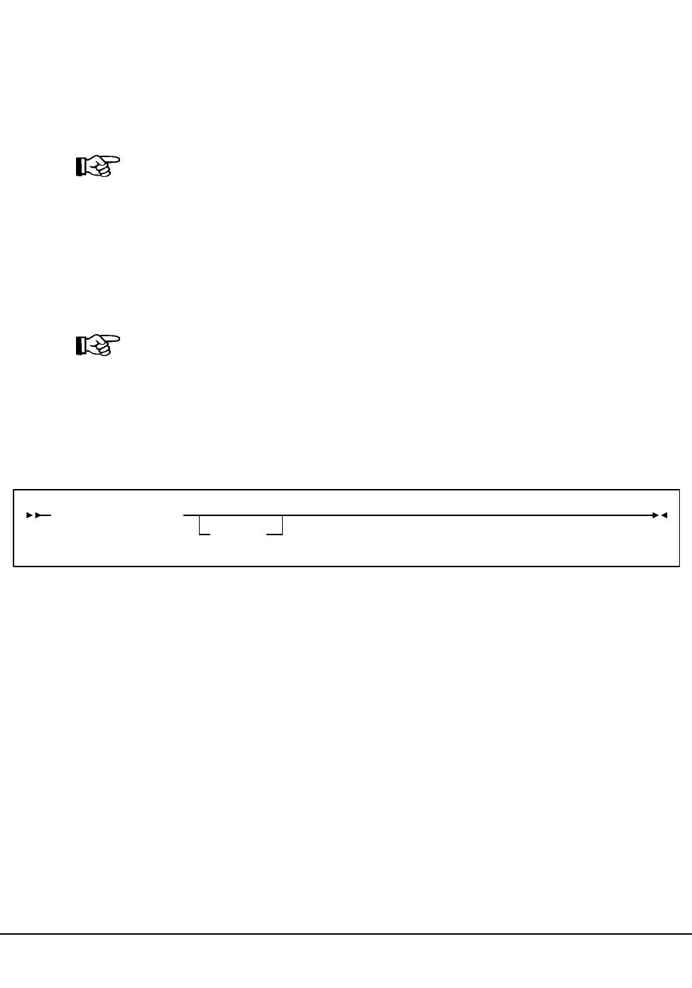
Chapter 4. Utility Functions 249
1st ed., 6/30/04 - 312579601
Enter Cartridges Utility
The Enter Cartridges utility permits you to batch enter cartridges into the library through
the CAP.
CAP Operating Instructions
Operating instructions for the CAP are provided in the HSC Operator’s Guide.
Note: When there are no more cartridges to be entered, open the CAP once again to ensure
that no cartridges are present in the CAP cells, and then close the CAP to complete
processing.
The utility returns a print file containing a list of the volumes entered to the virtual
machine which submitted the job. That virtual machine should copy the print file onto
disk. The listing is then available for you to initialize the internal magnetic labels in any
manner you choose, to inform the tape management system that the volumes are scratch
volumes, and/or to eject the volumes.
Note: The Enter Cartridges utility may not run concurrently with an Audit utility within
the same ACS. In addition, the Scratch Redistribution utility may not run concurrently
within the same ACS when the Enter Cartridges SCRatch option is specified.
If either of these conditions is not followed, an HSC message is generated and the utility
must be resubmitted.
Syntax
Utility Name
ENTEr
specifies that cartridges are to be batch entered into the library via a designated CAP.
Parameters
CAP
specifies a particular Cartridge Access Port to be used for the operation.
(cap-id)
cap-id identifies the Cartridge Access Port. The format for cap-id is AA:LL:CC
where AA is the ACS number (hexadecimal 00-FF), LL is the LSM number
(hexadecimal 00-17), and CC is the CAP number.
Allowable values for CC are:
ENTEr CAP(cap-id)
SCRatch
Enter Cartridges

250 VM/HSC 6.0 System Programmer’s Guide
1st ed., 6/30/04 - 312579601
00
• For 4410 and 9310 LSMs, standard 21-cell CAP or the right-hand 40-cell
enhanced CAP
• For 9360 LSMs, the 20-cell WolfCreek CAP
• For 9740 LSMs, fixed rack 14-cell or 10-cell removable magazine CAP
• For SL8500 libraries, the CAP consists of 3, 13-cell removable magazines.
01
• For 4410 and 9310 LSMs, left-hand 40-cell enhanced CAP
• For 9360 LSMs, the 30-cell WolfCreek optional CAP
• For SL8500 libraries, this is an optional CAP consisting of 3, 13-cell
removable magazines.
02
priority CAP (PCAP) for a 4410 or 9310 LSM enhanced CAP or for a
9360 LSM CAP.
SCRatch
When SCRatch is specified, it causes volumes to be put into scratch status.
JCL Requirements
The following definitions apply to the Enter Cartridges utility JCL:
SLSPRINT
output messages from the utility.
SLSIN
input to the utility in the form of control statement card images.
Invoking the Enter Cartridges Utility
The easiest way to run utilities is to execute the ACS UTIL exec by entering the following
command:
EXEC ACS UTIL ENTER
Execution of the statement results in the ACSUTIL SLKJCL file:
ACSUTIL SLKJCL File
/JOB jobname SLUADMIN
/PARM MIXED
/FILE SLSPRINT DEV PRNT CLASS A
/FILE SLSIN *
* ENTER CAP(capid)
Enter Cartridges

Chapter 4. Utility Functions 251
1st ed., 6/30/04 - 312579601
To execute the utility:
1. Delete the lines in the template that are not required, or leave the comment indicator
(*) in column one.
2. Remove the comment indicator from the desired lines.
3. Specify values for the desired parameters.
4. the parameters that are not desired.
5. Enter the command ‘‘FILE.’’
The job file is then submitted to the ACS service machine for execution.
JCL Example
The following example shows JCL for entering a cartridge(s) into a CAP. The volume(s) is
placed into scratch status.
JCL for Entering Cartridges in a CAP
Output Description
Output resulting from the execution of the Enter Cartridges utility includes:
• a listing of input commands with appropriate messages when syntax errors occur (see
Figure 14 on page 252)
• console messages informing the console operator when new volumes are entered
• messages associated with error conditions resulting from an unsuccessful attempt to
enter cartridges
• updated library control data set containing new volumes with the proper scratch
dispositions.
/JOB jobname SLUADMIN
/PARM MIXED
/FILE SLSPRINT DEV PRNT CLASS A
/FILE SLSIN *
ENTER CAP(01) SCRATCH
Enter Cartridges

252 VM/HSC 6.0 System Programmer’s Guide
1st ed., 6/30/04 - 312579601
SLUADMIN (n.n.n) StorageTek Automated Cartridge System Utility PAGE 0001
TIME hh:mm:ss Control Card Image Listing DATE yyyy-mm-dd
ENTER CAP(01)
SLUADMIN (n.n.n) StorageTek Automated Cartridge System Utility PAGE 0002
TIME hh:mm:ss Enter Cartridges Utility DATE yyyy-mm-dd
SLS0211I Volume C83040 successfully entered into library
SLS0211I Volume C84181 successfully entered into library
SLS0211I Volume C84182 successfully entered into library
SLS0211I Volume C84180 successfully entered into library
SLS0211I Volume C83039 successfully entered into library
SLS0155I Condition code for utility funtion is 0
Figure 14. Enter Cartridge Utility Sample Output
Enter Cartridges

Chapter 4. Utility Functions 253
1st ed., 6/30/04 - 312579601
Journal Offload Utility
The Journal Offload utility allows you to offload one or both of the journals on a given
host without backing up the control data set. It is extremely important that you archive the
offloaded journals, in the event that these journals are required for a restore operation.
The HSC can be operational while the Journal Offload utility is executing.
Syntax
Utility Name
OFFLoad
specifies that a journal offload is to be performed.
Parameters
None.
JCL Requirements
The following definitions apply to the Journal Offload utility program JCL:
SLSPRINT
the message output data set.
SYSPRINT
SLUOFFLD message output.
SLSCNTL
DD statement naming the primary library control data set.
SLSCNTL2
the secondary copy of the control data set.
SLSSTBY
the standby copy of the control data set.
SLSJRN01
the first of two journals on the given host.
SLSJRN02
the second of two journals on the given host. This statement is required only if both
journals are to be offloaded. If specified, the SLSOFF02 statement is also required.
SLSOFF01
the created offload data set for the first journal (SLSJRN01).
OFFLoad
Journal Offload

254 VM/HSC 6.0 System Programmer’s Guide
1st ed., 6/30/04 - 312579601
SLSOFF02
the created offload data set for the second journal (SLSJRN02).
Note: The offload data sets created by SLSOFF01 and SLSOFF02 must be allocated
on DASD. You can then copy the offloaded DASD data sets to tape if you desire.
SLSIN
input to the utility in the form of control statement card images.
Invoking the Journal Offload Utility
The easiest way to run utilities is to execute the ACS UTIL exec by entering the following
command:
EXEC ACS UTIL OFFLoad
Execution of the statement results in the ACSUTIL SLKJCL file:
ACSUTIL SLKJCL File
To execute the utility:
1. Delete the lines in the template that are not required, or leave the comment indicator
(*) in column one.
2. Remove the comment indicator from the desired lines.
3. Specify values for the desired parameters.
4. Delete the parameters that are not desired.
5. Enter the command ‘‘FILE.’’
The job file is then submitted to the ACS service machine for execution.
/JOB jobname SLUADMIN
/PARM MIXED
/FILE SLSPRINT DEV PRNT CLASS A
/FILE SYSPRINT DEV PRNT CLASS A
/FILE SLSCNTL DEV <500> DSN <dsname>
/FILE SLSJRN01 DEV <502> DSN <dsname>
/FILE SLSJRN02 DEV <503> DSN <dsname>
/FILE SLSOFF01 DEV <504> DSN <dsname>
/FILE SLSOFF02 DEV <505> DSN <dsname>
/FILE SLSIN *
* OFFLOAD
Journal Offload

Chapter 4. Utility Functions 255
1st ed., 6/30/04 - 312579601
JCL Example
The following example shows JCL for the offload of both journals.
JCL for Offload of Journals
Output Description
Output resulting from the execution of the Journal Offload utility (see Figure 15 on page
256) includes:
• the journal(s) is copied to the offload data set(s)
• the journal(s) is reset
• messages associated with error conditions resulting from an unsuccessful attempt to
execute the Journal Offload utility
• a condition code indicating successful or unsuccessful completion of the utility.
/JOB jobname SLUADMIN
/PARM MIXED
/FILE SLSCNTL DEV vaddr DSN control.set.name
/FILE SLSOFF01 DEV vaddr DSN offload.file1
/FILE SLSOFF02 DEV vaddr DSN offload.file2
/FILE SLSJRN01 DEV vaddr DSN journal.file1
/FILE SLSJRN02 DEV vaddr DSN journal.file2
/FILE SLSPRINT DEV PRNT CLASS A
/FILE SYSPRINT DEV PRNT CLASS A
/FILE SLSIN *
OFFLOAD
Journal Offload

256 VM/HSC 6.0 System Programmer’s Guide
1st ed., 6/30/04 - 312579601
SLUADMIN (n.n.n) StorageTek Automated Cartridge System Utility PAGE 0001
TIME hh:mm:ss Control Card Image Listing DATE yyyy-mm-dd
OFFLOAD)
SLUADMIN (n.n.n) StorageTek Automated Cartridge System Utility PAGE 0002
TIME hh:mm:ss Journal Offload Utility DATE yyyy-mm-dd
SLS0282I Journal at DDname SLSJRN01 successfully offloaded to data set defined by SLSOFF01 DD statement
SLS0282I Journal at DDname SLSJRN02 successfully offloaded to data set defined by SLSOFF02 DD statement
SLS0191I Journal at DDname SLSJRN01 successfully reset
SLS0191I Journal at DDname SLSJRN02 successfully reset
SLS0155I Condition code for utility functions is 0
Figure 15. Journal Offload Utility Sample Output
Journal Offload

Chapter 4. Utility Functions 257
1st ed., 6/30/04 - 312579601
Move Utility
The MOVe utility permits you to request the HSC to move a single volume, a list of
volumes, or a range of volumes to other locations within an ACS.
MOVe Considerations
You should be aware of the following considerations before attempting to use the MOVe
utility:
• Movement of volumes to all LSMs is done on a first-come first-served basis. As
volumes are moved, should an LSM become fully populated before the move request
is satisfied for that LSM, the move request continues with the movement of volumes
designated for the next LSM specified in the request. An LSM is fully populated
when all available cells contain tape cartridges. This process continues until the
entire move request is completed or all destination LSMs are full.
• Moves are performed one at a time so that other LSM work can be done.
• The target LSM for the move request must be specified. Optionally, the specific
panel within the target LSM may also be specified. Cartridges may be moved from
one panel to another panel within the same LSM, but cartridges may not be moved
from one location to another on the same panel. Also, cartridges cannot be moved to
frozen panels in an LSM which is the target of a move.
The cartridges being moved may be specified in the following ways:
- move a single cartridge or a group of cartridges (specified by a VOLSER, a list
of VOLSERs, or a range of VOLSERs)
- move the contents of a specified column, row, or entire panel (specified using
the parameters FromLSM,Panel,Row,Column)
• An entire panel or panels can be emptied by specifying the Panel parameter without
the Row or Column parameters. Any panels that are specified in the panel-list are
excluded as destination panels if cartridges are being moved within the same LSM.
Note: Other cartridge activity occurring in the LSM can result in cartridges being
placed in cells in a panel that is being emptied by the MOVe utility.
Refer to the appropriate ACS hardware document for information about LSM outer
and inner wall panel layouts.
Move

258 VM/HSC 6.0 System Programmer’s Guide
1st ed., 6/30/04 - 312579601
Syntax
Utility Name
MOVe
specifies a move request.
Parameters
Flsm
The ‘‘From’’ LSMid in the format ‘‘AA:LL’’ that the cartridges are to be moved
from. If you designate the Flsm parameter, you may not designate the Volume
parameter.
(lsm-id)
LSM identifier name. LSMs are specified as AA:LL, where AA is the ACSid and
LL is the LSMid. An LSMid is made up of the ACSid (hexadecimal 00-FF) and
the LSM number (hexadecimal 00-17) separated by a colon (:).
Panel
panel number to be moved from. This parameter has a corequisite of the Flsm
parameter and is required.
An entire panel can be emptied if the Row and Column parameters are not specified.
(panel-list)
A one or two digit panel number. Ranges are not valid. This parameter cannot
contain a list if a list is specified for the Row or Column parameter.
Panels specified by panel-list are excluded as destination panels if cartridges are
being moved within the same LSM.
Row
list of Rows to be moved from. This parameter has a corequisite of the Panel
parameter.
MOVe Parameters
Parameters:
Flsm(lsm-id)Panel(panel-list)
Volume(vol-list)
Row(row-list)
Column(column-list)
TLsm(lsm-list)
TPanel(panel)
Move

Chapter 4. Utility Functions 259
1st ed., 6/30/04 - 312579601
(row-list)
A one or two digit row number or list of row numbers. The maximum list
allowed is four rows. However, this parameter cannot contain a list if a list was
specified for the Column parameter. Ranges are not valid.
Column
list of Columns to be moved from. This parameter has a corequisite of the Row
parameter and is optional. If this parameter is not specified, all columns will be
moved for the rows specified.
(column-list)
A one or two digit column number or list of column numbers. This parameter
cannot contain a list if a list was specified for the Row parameter. Ranges are
not valid.
Note: Refer to the appropriate ACS hardware document for information about LSM panel,
row, and column locations and layouts.
Volum e
volumes to be moved.
(vol-list)
A list of volumes (a maximum of 100 can be specified) or a range of volumes. If
you specify the Volume parameter, you may not specify the Flsm parameter.
TLsm
The target LSM(s). This is a required parameter. LSMs are specified as AA:LL,
where AA is the ACSid and LL is the LSMid. The ACSid:
• must be identical to the Flsm parameter ‘‘aa’’ (ACSid), or
• must be the same ACS in which the volume resides if the Volume
parameter is specified.
(lsm-list)
A list of LSMs (a maximum of 24 can be specified). Ranges are invalid. An
LSMid (lsm-id) is made up of the ACSid (hexadecimal 00-FF) and the LSM
number (hexadecimal 00-17) separated by a colon (:).
TPanel
the panel in the TLsm to move the cartridge(s) to. This parameter is optional.
(panel)
The one or two digit panel number. This parameter cannot contain a list or
range.
Move

260 VM/HSC 6.0 System Programmer’s Guide
1st ed., 6/30/04 - 312579601
JCL Requirements
The following definitions apply to MOVe utility JCL:
SLSPRINT
output messages from the utility program.
SLSIN
input to the utility in the form of control cards.
Invoking the Move Utility
The easiest way to run utilities is to execute the ACS UTIL exec by entering the following
command:
EXEC ACS UTIL MOVe
Execution of the statement results in the ACSUTIL SLKJCL file:
ACSUTIL SLKJCL File
To execute the utility:
1. Delete the lines in the template that are not required, or leave the comment indicator
(*) in column one.
2. Remove the comment indicator from the desired lines.
3. Specify values for the desired parameters.
4. Delete the parameters that are not desired.
5. Enter the command ‘‘FILE.’’
The job file is then submitted to the ACS service machine for execution.
/JOB jobname SLUADMIN
/PARM MIXED
/FILE SYSPRINT DEV PRNT CLASS A
/FILE SLSIN *
* MOVE Flsm(lsm-id) Panel(panel-list) Row(row-list) Column(col-list)
* Tlsm(lsm-list) TPanel(panel)
* MOVE Volume(vol-list) TLsm(lsm-list) TPanel(panel)
Move

Chapter 4. Utility Functions 261
1st ed., 6/30/04 - 312579601
JCL Examples
The following example shows JCL for moving a single volume from a panel to another
panel within the same LSM.
The example JCL moves a volume from LSM 00:01, Panel 08, Row 05, Column 02 to the
same LSM (00:01) to Panel 09.
JCL for Moving a Single Volume within the Same LSM
The example JCL moves volumes 000345, 000357, 000367, and 000360 to LSM 00:02,
Panel 06.
Move Several Volumes From an LSM to Another LSM
Output Description
• Typical outputs resulting from the execution of the MOVe utility include:
• a listing of input commands with appropriate messages when syntax errors occur
• messages associated with error conditions resulting from an unsuccessful attempt to
execute unselect processing
• messages indicating actions occurring during processing (see Figure 16 on page 262)
• an updated control data set indicating the volume is moved
• a condition code indicating successful or unsuccessful volume movement (see Figure
16).
/JOB jobname SLUADMIN
/PARM MIXED
/FILE SYSPRINT DEV PRNT CLASS A
/FILE SLSIN *
MOVE FLSM(00:01) PANEL(00) ROW(05) COLUMN(02) TLSM(00:01) TPANEL(09)
/JOB jobname SLUADMIN
/PARM MIXED
/FILE SYSPRINT DEV PRNT CLASS A
/FILE SLSIN *
MOVE VOLUME(000345 000357 000367 000360) TLSM(00:02) TPANEL(06)
Move

262 VM/HSC 6.0 System Programmer’s Guide
1st ed., 6/30/04 - 312579601
SLUADMIN (n.n.n) StorageTek Automated Cartridge System Utility PAGE 0001
TIME hh:mm:ss Control Card Image Listing DATE yyyy-mm-dd
MOVE FLSM(00:04) PANEL(00) TLSM(00:11)
SLUADMIN (n.n.n) StorageTek Automated Cartridge System Utility PAGE 0002
TIME hh:mm:ss Move Volume Utility DATE yyyy-mm-dd
SLS1950I Volume X00609 moved from location 00:04:00:00:00 to location 00:11:00:00:14
SLS1950I Volume X00594 moved from location 00:04:00:00:01 to location 00:11:01:00:09
SLS1950I Volume X00578 moved from location 00:04:00:00:02 to location 00:11:02:00:09
SLS1950I Volume X00562 moved from location 00:04:00:00:03 to location 00:11:03:00:09
SLS1950I Volume X00546 moved from location 00:04:00:00:04 to location 00:11:04:00:09
SLS1950I Volume X00638 moved from location 00:04:00:00:05 to location 00:11:05:00:09
SLS1950I Volume X00659 moved from location 00:04:00:00:06 to location 00:11:06:00:09
SLS1950I Volume X00680 moved from location 00:04:00:00:07 to location 00:11:07:00:09
SLS1950I Volume X00431 moved from location 00:04:00:00:08 to location 00:11:08:00:09
SLS1950I Volume X00538 moved from location 00:04:00:00:09 to location 00:11:09:00:09
SLS1156I 10 volume(s) moved
SLS1155I 10 volume(s) moved to LSM 00:11
SLS0155I Condition code for utility function is 0
Figure 16. MOVe Utility Sample Output
Move
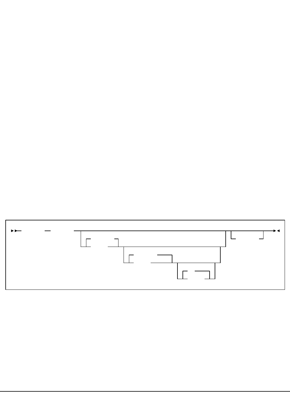
Chapter 4. Utility Functions 263
1st ed., 6/30/04 - 312579601
Performance Log Reblocker Utility
The Performance Log Reblocker utility is used by sites sharing an ACS between MVS and
VM hosts. The utility is used to reformat the VM performance log data to a common
format similar to that of the MVS/SMF data. This data is then used as input for the
Activities Report utility. The Performance Log Reblocker utility is required to reconstruct
the original-image SMF data; different versions are provided to execute in the CMS and
MVS environments.
This utility prepares the generated performance log (SMF data) for use by the Activities
Report utility.
SMF records passed to the SCP (see the glossary for a definition of SCP) are variable in
length and can be up to 32K bytes long. The SCP breaks these records into sections that fit
in a VM punch spool file, and passes reblocking information with each segment.
The CMS version takes SCP performance log output (without any header/trailer data) and
reads it into a CMS file without altering the internal format of the records. The CMS
version of the Activities Report utility (SLUACTV EXEC) reconstructs the original SMF
record images during its own execution.
The MVS version reads the SCP performance log data and creates data set records
reblocked into the original SMF record format and length. Then, as specified by the
PERFJCL trailer data, the reblocked SMF data optionally may be merged with SMF data
created on the MVS system.
Syntax (CMS Statement)
Performance Log Reblocker utility
Parameters
spoolid
the VM spoolid of a punch file in the caller’s virtual reader. This parameter is
required.
fname
the CMS filename of the output file. The default is SLUPERF.
ftype
the CMS filetype of the output file. The default is PERFLOG.
SLUPERF spoolid
SLUPERF
fname
PERFLOG
fname
A2
fmode
(APPend
Performance Log Reblocker

264 VM/HSC 6.0 System Programmer’s Guide
1st ed., 6/30/04 - 312579601
fmode
the CMS filemode of the output file. The default is A2. (APPend specifies that the
records from the reader file are appended to the specified CMS file if it exists.
Invoking the Performance Log Reblocker Utility in CMS
The easiest way to run this utility in CMS is to execute the following EXEC by entering:
EXEC ACS UTIL SLUPERF
Execution of the statement produces the ACSCMS EXEC file:
ACSCMS EXEC
To execute the Reblocker utility, perform the following steps:
1. Remove the comment indicator (*) on the left, and specify the spoolid of the reader
file and the name of the data output file.
2. Enter the command ‘‘FILE.’’
Invoking the Performance Log Reblocker Utility in MVS
To invoke the Performance Log Reblocker utility in MVS, certain steps must occur on
VM.
1. The PERFJCL system profile (SYSPROF) parameter must be specified indicating
the CMS file that contains the performance log header/trailer data.
2. The SCP SET PERFLOG command must be executed (normally within the
SYSPROF file) by specifying one of the following formats:
• To spool the data to a virtual machine running MVS on the same CPU:
SET PERFLOG ON (CLASS class TO mvsuserid
where:
ON
enables performance log recording
class
specifies the virtual spool file class to be read by the MVS virtual machine
mvsuserid
specifies the MVS virtual machine
• To send the data to a different CPU running MVS:
&TRACE ALL
* EXEC SLUPERF <spoolid> <fname|SLUPERF> <ftype|PERFLOG> <fmode|A1>
Performance Log Reblocker

Chapter 4. Utility Functions 265
1st ed., 6/30/04 - 312579601
SET PERFLOG ON (CLASS class TO JOB AT mvsnode
where:
ON
enables performance log recording
class
specifies the virtual spool file class to be used while transferring the spool file
JOB
specifies to transmit the virtual spool file as a job to the MVS system
mvsnode
specifies the node of the MVS system
3. The SMF parameters must be specified by the SCP SET PERFLOG command,
which is normally included within the SYSPROF file. (Refer to the SCP command
descriptions found in Chapter 2, ‘‘Commands, Control Statements, and Utilities’’ in
the HSC Operator’s Guide).
JCL Requirements
To invoke the Performance Log Reblocker utility in MVS, the performance log data must
be prefaced by the PERFJCL header data. This process is described in ‘‘Modifying
Performance Log Header/Trailer JCL (Optional)’’ in the HSC Installation Guide.
Performance Log Reblocker

266 VM/HSC 6.0 System Programmer’s Guide
1st ed., 6/30/04 - 312579601
Reconfiguration Utility
The Reconfiguration utility is used as part of a four-stage process to create a new copy of
the control data set when library hardware configurations change, such as the addition of
drives or LSMs, but when information regarding the location of cartridges in the library
must be retained from the original control data set.
Note: This utility requires a 2.1-level CDS.
The four stages include:
• performing a LIBGEN to create the new hardware configuration
• executing the SLICREAT procedure to format the new CDS that will hold the
information transferred from the old CDS during the execution of the
Reconfiguration utility
• executing the Reconfiguration utility to transfer current cartridge information from
the old CDS to the new CDS taking into account the hardware configuration changes
made
• possibly executing a partial audit that may be necessary to make final corrections to
the CDS contents for panels that may have changed as a result of hardware
configurations, such as the addition of drive panels.
The Reconfiguration utility executes as an SCP job with the HSC at the base service level
and runs as a special invocation of the HSC. The Reconfiguration utility uses as input the
CDSDEF control statement (points to the old CDS) as its information source and the
RECDEF control statement (points to the newly formatted CDS) as the target where the
updated information is stored.
Reasons for Running the Reconfiguration Utility
The Reconfiguration utility minimizes the amount of time that the library is unavailable
for your use due to library modifications. Some typical examples of library modifications
are:
• an LSM panel is reconfigured (possibly by adding a drive panel to the LSM)
• an LSM is added to the existing configuration. Usually, this causes a change to the
configuration of some of the existing LSMs since PTP panels replace panels that are
currently full wall panels.
• an ACS is added to the library
• an LSM, or an entire ACS, is removed from the library.
Reconfiguration

Chapter 4. Utility Functions 267
1st ed., 6/30/04 - 312579601
Since the LIBGEN macros define the various physical aspects of a library, most changes
or modifications affecting the physical configuration of the library require that
corresponding LIBGEN macro(s) be updated. Any update to the LIBGEN (except changes
made via the SET utility) requires that a new library control data set be created. To do this,
run your LIBGEN through the SLICREAT program (refer to ‘‘Executing the SLICREAT
Program’’ in the HSC Installation Guide) and use that output file along with your old CDS
as input to the Reconfiguration utility (refer to “Reconfiguration CDS Definition
(RECDEF) Control Statement” on page 98).
Note: The SET utility allows many changes to be made without executing the
Reconfiguration utility to accomplish a desired functional change. Refer to the “SET
Utility” on page 299 for a description of the SET utility.
Considerations Before Running Reconfiguration
Consider the following items before executing the Reconfiguration function:
• If the HSC control data set is shared with an MVS host, run the reconfiguration from
the MVS host. Refer to HSC System Programmer’s Guide for instructions.
• Make sure you are familiar with VM fundamentals and configuring DASD in a VM
environment.
• Make sure you are familiar with the following:
-SCP
- SCP system files
- SLIMDISK EXEC
- old and new control data set minidisks
- old and new control data set names
- writing and submitting SLKJCL to the SCP.
• The control data set resides in a new data set when reconfiguration completes, and
may also reside on a new virtual address depending on your data center
configuration.
DASD Considerations in a VM-only Environment
The following DASD considerations apply to running the Reconfiguration function in a
VM-only environment:
• If you are using full-volume minidisks for the HSC control data set, StorageTek
recommends using OS-format minidisks to allow allocation of multiple data sets on
the same real volume for reconfiguration purposes. Use the same vaddr for
SLSCNTL and DBPRMNEW, and the same vaddr for SLSCNTL2 and
DBSHDNEW in ACS SYSPROF.
• If you are using partial volume minidisks for the HSC control data set, either
OS-format or CMS reserved minidisks may be used for reconfiguration. The old and
new control data set must be the same cylinder size and format.
Reconfiguration

268 VM/HSC 6.0 System Programmer’s Guide
1st ed., 6/30/04 - 312579601
• The old and new control data sets must be on volumes that are configured properly
for real reserve/release to all hosts running HSC. (Refer to the IBM documentation
for your environment.)
• If it is necessary to copy the control data set to another minidisk, use the BACKup
and RESTore utilities to ensure proper reset of database flags.
How the Reconfiguration Utility Functions
During a reconfiguration, volume information is copied from the old CDS to the new
CDS. If the same LSMid exists on both the old and new CDS, volume information is
copied for all panels as long as the panel type did not change.
Notes:
1. LSM types must be the same, or no volumes in those LSMs are copied. 4410 and
9310 LSMs are considered to be the same LSM type.
2. An example of a ‘‘changed’’ panel type is if a drive panel replaces a cell panel. In
this case, volume information on that panel is not copied.
When panels are frozen by the SET FREEZE utility, the resulting panel status in the new
CDS is determined by these conditions:
• If the panel types match on the old and new CDS, the panel is frozen only if the panel
on the old CDS is frozen.
• If the panel types do not match on the old and new CDS, the panel is frozen only if
the panel on the new CDS is frozen.
The Reconfiguration utility is executed as an SCP job to transfer data from the old control
data sets to the new control data sets.
Note: Reconfiguration executes under the Base service level only.
Before executing the Reconfiguration utility, it is highly recommended that you run the
Volume Report utility, which specifies the ACS and/or ACS and LSM options.
The volume report detects any errant and/or selected volume plus cell-allocated, but
empty, conditions. If any of these conditions exist, it is recommended that each condition
be cleared before running the Reconfiguration utility. If not cleared, the condition is
copied to the newly created control data set.
An exception exists for selected volumes that are copied and marked unselected in the new
control data set. If duplicate VOLSERs exist, run the AUDIt utility before running the
Reconfiguration utility.
The net result of executing the Reconfiguration utility (process) is the creation of new
control data sets that must be used for HSC execution from this point.
Caution: Following a reconfiguration, all LSMs are in offline, manual mode and must
be brought online. Commands that are dependent on the LSMs being online
Reconfiguration
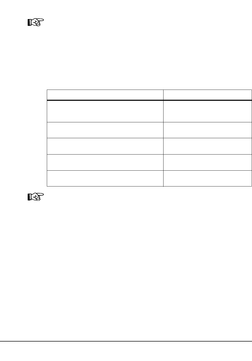
Chapter 4. Utility Functions 269
1st ed., 6/30/04 - 312579601
(including all commands used when automated mounts or dismounts are necessary)
need to be issued after the LSMs are brought online.
Note: ALL new control data sets (primary, secondary, and standby) must conform to the
library hardware.
I/O Considerations
Reconfiguration is I/O intensive. For this reason, it is highly recommended that you
reduce the number of scratch volumes as much as possible to shorten reconfiguration time.
Refer to “Minimizing I/O Time” on page 270 for more information. The following table
details I/O requirements for various situations.
Note: Shadowing is disabled during the reconfiguration process. If a new secondary CDS
is used, the final step of reconfiguration copies the new primary to the new secondary.
The quantities shown above represent most of the I/O done by reconfiguration. Depending
on the ratio of cells to volumes, and nonscratch to scratch volumes, the number of scratch
volumes can easily be the prime determinant of the number of I/O operations performed
by Reconfiguration.
Table 13. I/O Requirements
Condition: Number of I/Os:
For every volume in the old CDS that remains in the
new CDS (volumes remain if their home panels have
not been changed)
5
For every scratch volume in the old CDS that remains
in the new CDS
38-58 additional
For every errant volume in the old configuration that
remains in the new configuration
11 additional
For every cell in the old configuration that remains in
the new configuration
1 additional
For every panel in the old configuration that remains
in the new configuration
5 additional
Reconfiguration
270 VM/HSC 6.0 System Programmer’s Guide
1st ed., 6/30/04 - 312579601
Minimizing I/O Time
Any or all of the following approaches will reduce reconfiguration time:
• Using a solid state disk (SSD) device (such as StorageTek’s 4080)
• Having no scratch tapes in the old CDS, rather than many scratch tapes
Note: Reconfiguration to real DASD with many scratch volumes has been known to
take hours of wall clock time.
• Minimize I/O to the CDS copies by defining only the new primary CDS copy to
RECONFIG. Afterward, copy the new primary CDS copy to the new secondary and
standby CDS copies as needed.
A way to minimize I/O time is to copy all CDSs to an SSD device before reconfiguration.
To use the SSD, create a multiple-step reconfiguration procedure to:
1. Copy the old and new CDSs to the SSD data set. If shadowing is enabled, both the
primary and the secondary must be copied to the SSD data set.
Warning: Do not include CDSDEF or RECDEF statements in the PARMLIB
control statements. (If included, they override the statements for the SSD.)
2. Perform the reconfiguration using the SSD data sets as the old and new CDSs.
3. Copy the new SSD CDSs to the real, new CDSs on DASD. The old CDSs need not
be copied since they have not been updated.
Running a Successful Reconfiguration
While the Reconfiguration utility is in process, the library is unavailable to the user.
Notes:
1. Deviations to the reconfiguration procedure may be required as determined by
the system programmer familiar with the environment.
2. Unless otherwise stated, all operations are on MAINTSTK.
The steps necessary to achieve a successful reconfiguration are as follows:
1. Run the Database Decompile utility to create a new LIBGEN.
Caution: Do not rely on old LIBGENs for accuracy. If you do not perform this
step, modifications made to the CDS (e.g., changes entered from the SET utility)
will not be added to the LIBGEN. Thus, you may encounter a mismatch between
your CDS and LIBGEN.
Reconfiguration

Chapter 4. Utility Functions 271
1st ed., 6/30/04 - 312579601
2. Identify any proposed changes to the host system’s Configuration Plan. It may be
necessary to update the RIOGEN (i.e., DMKRIO, HCPRIO) to reflect changes to the
hardware addresses.
3. Code the necessary modifications in the LIBGEN macros.
Note: Changing or deleting an ACSid or LSMid in the LIBGEN is not supported by
the HSC, except for the last LSMid defined for any ACS or the last ACS defined in
the LIBGEN.
4. Assemble the LIBGEN following the procedures in ‘‘Assemble the LIBGEN File’’ in
the HSC Installation Guide.
5. Ensure that the current primary CDS copy (as shown by the Display CDS command)
is the primary copy of the old CDS input to RECONFIG. If the CDS copies need to
be rotated into a different sequence, use the procedure described under “Reassigning
Control Data Set Names in Database Heartbeat Record” on page 60.
6. Stop execution of the HSC on all hosts except the one being used to run the
Reconfiguration utility.
7. Log on to STKACS.
8. Stop task SLSBINIT on STKACS by issuing the SCP command:
STOP taskid
This allows the SCP to remain up to run the BACKup utility. Refer to the HSC
Operator’s Guide for explanations of SCP commands.
9. Verify that SLSBINIT and class U job readers are idle by issuing on STKACS the
SCP command:
QUERY ACTIVE
10. From MAINTSTK, back up the control data set by issuing the following command:
EXEC ACS UTIL BACKUP
Wait for successful job completion.
11. Stop the SCP on the remaining VM host by issuing the following command on
STKACS:
STOPSCP
12. Issue the following command to purge the service machine’s reader on STKACS:
CP PURGE READER ALL
Reconfiguration

272 VM/HSC 6.0 System Programmer’s Guide
1st ed., 6/30/04 - 312579601
13. Perform the following tasks to prepare for reconfiguration:
a. Issue the following commands:
ACCESS 191 A
ACCESS 254 B
ACCESS 255 C
The 191-disk is MAINTSTK 191, the 254-disk is the RUN-disk, and the
255-disk is STKACS 191.
b. Make a backup copy of the ACS SYSPROF by issuing:
COPY ACS SYSPROF B ACSOLD SYSPROF A (REPLACE
c. Copy ACS SYSPROF from the RUN-disk (B) to the A-disk. This allows you to
modify ACS SYSPROF for the Reconfig and ensure it is correct before placing
it back on the RUN-disk.
COPY ACS SYSPROF B ACS SYSPROF A
d. XEDIT ACS SYSPROF A to describe the new data sets and LIBGEN module.
In particular, modify the following parameters:
Comment out any AUTOJOB statements.
LIBGEN file name of the LIBGEN load module.
SLSCNTL DSN of the new primary control data set (for SLICREAT).
Comment out the old statement to use later (see step 13n on
page 4-95).
SLSCNTL2 DSN of the new secondary control data set (for SLICREAT).
Comment out the old statement to use later (see step 13n on
page 4-95).
SLSSTBY DSN of the new standby control data set (for SLICREAT).
SLSJRNxx DSNs of any new journal data sets (for SLICREAT).
SLSOFFxx DSNs of new journal off-load data sets.
SLSBKUP DSN of new backup data set. STATION list of station
addresses should be corrected.
DBPRMNEW DSN of the new primary control data set (for RECONFIG).
Copy the unit address and DSN from the new SLSCNTL
statement. DBSHDNEW DSN of the new secondary control
data set (for RECONFIG). Copy the unit address and DSN
from the new SLSCNTL2 statement.
Reconfiguration
Chapter 4. Utility Functions 273
1st ed., 6/30/04 - 312579601
Note: Virtual device addresses may need to be changed in ACS SYSPROF
when adding new data set names.
e. Copy the updated SYSPROF to the RUN-disk.
COPY ACS SYSPROF A ACS SYSPROF B (REPLACE
f. Allocate the new data sets using SLIMDISK.
Note: Review all the DASD considerations before allocating data sets. Refer to
‘‘Calculating DASD Space’’ in the HSC Installation Guide.
g. Issue the following command to create a job to initialize the new library data
sets:
EXEC ACS UTIL SLICREAT (NOSEND
h. Verify that the information is correct and file the job.
Note: Be sure to add /FILE statements for all journals for all hosts.
i. Issue the following command to create a new production startup job file:
EXEC ACS UTIL HSCINIT (NOSEND
j. Verify that the information is correct and file the job. Modify the data set,
volume, and unit information as necessary.
k. Copy the new startup job file to the STKACS ACS191-disk.
COPY HSCINIT SLKJCL A HSCINIT SLKJCL C
l. Enter the following commands on STKACS. Then, reaccess the RUN-disk to
access the new LIBGEN and SYSPROF, load the LIBGEN into memory, and
start the SCP.
ACCESS 191 A
ACCESS 192 D
NUCXLOAD libgen
ACS INIT (NOJOB
libgen is the name of the new LIBGEN module created in step 4 on page 259.
m.Issue the following command from the MAINTSTK machine:
EXEC ACS SUBMIT SLICREAT SLKJCL
Wait for the job to complete.
n. XEDIT ACS SYSPROF A to restore the SLSCNTL, SLSCNTL2, and
SLSSTBY DSNs to the old names by removing the comments from the old
Reconfiguration

274 VM/HSC 6.0 System Programmer’s Guide
1st ed., 6/30/04 - 312579601
statements and deleting the DSNs created in step 13d on page 260. Do not alter
DBPRMNEW or DBSHDNEW.
Note: Virtual device addresses may need to be changed in ACS SYSPROF
when adding new data set names.
o. Issue the following command to create a job to reconfigure the new library data
sets:
EXEC ACS UTIL RECONFIG (NOSEND
p. Verify that the information is correct and file the job. Modify the data set,
volume, and unit information as necessary.
q. Issue the following command:
COPY ACS SYSPROF A ACS SYSPROF B (REPLACE
r. Issue the following commands to recycle the SCP on STKACS:
STOPSCP ACCESS 192 D EXEC ACS INIT (NOJOB
s. Issue the following command:
ERASE ACS SYSPROF A
t. Issue the following command to submit the RECONFIG job created earlier:
EXEC ACS SUBMIT RECONFIG SLKJCL
The reconfiguration job starts the HSC and copies status information from the
old to the new control data set. Wait for the job to complete.
Note: If the Reconfig fails, look at the job log for an indication of the cause of
the failure.
u. Issue the following command on the STKACS service machine to shut it down:
STOPSCP
14. Log off the STKACS service machine.
15. Have the CSE make any necessary hardware changes.
/JOB jobname SLSBINIT
/PARM E(E086) F(23) MEMBER(XX) RECONFIG
/FILE SLSSYSXX *
/* DEFINE CONTROL DATA SETS */
CDSDEF DSN1=<prm.dsname>, VOL1=<vol1>, UNIT1=<unit1>
DSN2=<sec.dsname>, VOL2=<vol2>, UNIT2=<unit2> !
DSN3=<stb.dsname>, VOL3=<vol3>, UNIT3=<unit3>
/* DEFINE RECONFIG DATA SETS #/
RECDEF DSN1=<prmnew.dsname>, VOL1=<vol1>, UNIT1=<unit1> !
DSN2=<secnew.dsname>, VOL2=<vol2>, UNIT2=<unit2>
Reconfiguration
Chapter 4. Utility Functions 275
1st ed., 6/30/04 - 312579601
16. XEDIT ACS SYSPROF B to remove the comments from the AUTOJOB statements.
Note: Make sure that the AUTOJOB file name matches the new startup job file
created earlier.
Modify the SLSCNTL, SLSCNTL2, and SLSSTBY data set names to match the new
names.
17. Save ACS SYSPROF on the RUN-disk (B).
18. Issue the following command to restart the ACS service machine:
AUTOLOG STKACS
19. Change any startup files (SYSPROF, STARTUP JCL, and/or PROCs) for other hosts
to reflect the new configuration.
Notes: The MDISK links for other hosts may also need to be changed depending on
your configuration.
20. From MAINTSTK, back up the new control data set by issuing the following
command:
EXEC ACS UTIL BACKUP
21. Audit any panels that changed while reconfiguring the library.
Caution: When an LSM panel is replaced, the contents of the original panel are
not retained in the CDS. The entire new panel must be audited to update the
CDS.
22. When the reconfiguration completes successfully, issue on MAINTSTK:
ERASE ACSOLD SYSPROF A
Reconfiguration

276 VM/HSC 6.0 System Programmer’s Guide
1st ed., 6/30/04 - 312579601
Restore Utility
The RESTore utility provides a way to re-create the library control data set from a
previous backup copy of the data set. You also have the option to apply all journals
(maximum of 99 files per run) since the last backup, if journaling is enabled.
Caution: It is critical that you restore all data sets referenced by the HSC (primary,
secondary, standby). Failing to restore all data sets can cause CDS mismatches. Refer
to “Control Data Set Recovery” on page 58 and “Reassigning Control Data Set Names
in Database Heartbeat Record” on page 60 for additional information.
Prerequisites
Warning: The host software must be stopped on all hosts and the SCP must be
operational when this utility is executed.
Reasons for Running the RESTore Utility
The RESTore utility performs the following tasks:
• re-creates the library control data set from a backup copy
• applies contents of any journals having activity since the backup. This process occurs
only if you have designated that journals are enabled. See ‘‘SLIRCVRY Macro’’ in
the HSC Installation Guide for information about enabling journaling.
Notes: The HSC BACKup and RESTore utilities can be used as part of a procedure
to rename control data sets. Refer to “Reassigning Control Data Set Names in
Database Heartbeat Record” on page 60 for detailed information on renaming control
data sets.
How the RESTore Utility Functions
The RESTore utility is executed in the following phases:
• A hardware reserve is issued against the control data set.
• The library control data set is restored from a previous backup copy.
• If journaling is enabled, the installation optionally can apply journals (up to 99 files
per run) to the restored library control data set. It is the user’s responsibility to
include all journals and offload copies made since the last backup.
• The restored library control data set is duplicated in the secondary and standby
control data sets if secondary and standby control data sets are being used. Refer to
“Control Data Set Recovery” on page 58 for additional information about the control
data set recovery scheme.
• If GENerate (YES, Only, or Short) is specified in the RESTore JCL, output of the
discrepancies encountered is stored in the SLSAUDIT data set. For information on
resolving any discrepancies, see ‘“How to Handle BACKup/RESTore
Discrepancies” on page 283.
• The control data set is released, and the utility ends.
Restore
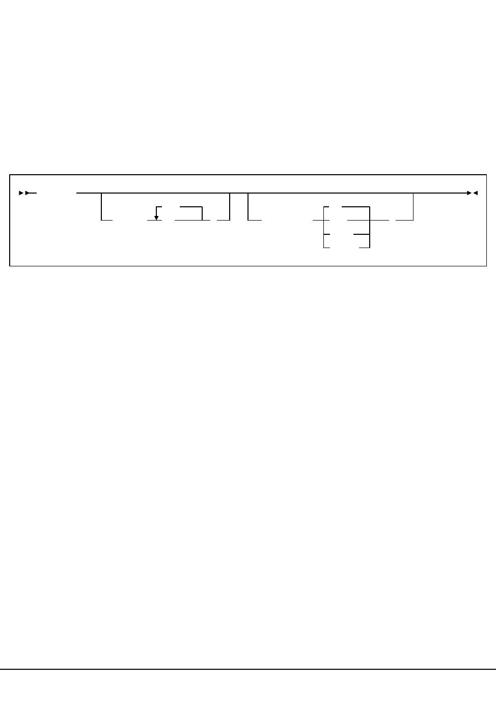
Chapter 4. Utility Functions 277
1st ed., 6/30/04 - 312579601
The RESTore utility does not reset the journals. It is recommended that a backup be
performed following the completion of the restore to reset the journals and reflect the
newly restored control data set.
Special Considerations for Control Data Sets Processing Independently
Special precautions should be taken for running BACKup and RESTore when
local/remote-linked libraries run control data sets independent of each other. These
precautions should be followed when the link connecting the local and remote libraries is
disrupted. Refer to “When CDS Copies Are Split Among Hosts After an Error” on page
213 for more information.
Syntax
Utility Name
RESTore
specifies that the restore operation is to be performed.
Parameters
APPly
optionally specifies whether or not the journals are to be applied to the restore
operation.
(YES)
specifies that journals are to be applied. YES is the default.
(NO)
specifies that journals are not to be applied.
GENerate
optionally specifies what statements are output to the SLSAUDIT data set and
whether or not control data sets are restored.
(NO)
specifies that NO statements are sent to the SLSAUDIT data set. The control
data sets are also restored. NO is the default.
(YES)
specifies that statements are sent to the SLSAUDIT data set. The control data
sets are also restored.
RESTore
APPly( NO
YES
)GENerate(
Only
Short
YES
NO
)
Restore

278 VM/HSC 6.0 System Programmer’s Guide
1st ed., 6/30/04 - 312579601
Note: If OPTion(Analyze) was specified for backup, this parameter should be
specified for the restore.
(Only)
specifies that all statements are sent to the SLSAUDIT data set. The CDS and
Journal /FILE statements need not be present. The control data sets are not
restored.
(Short)
specifies that Audit statements only are sent to the SLSAUDIT data set. The
control data sets are restored.
JCL Requirements
The following definitions apply to RESTore utility JCL:
SLSPRINT
output messages from the utility program.
SLSCNTL
the primary control data set.
SLSCNTL2
the secondary copy of the CDS (optional).
Note: SLSBKUP the backup data set. SLSSTBY a standby copy of the control data
set having only the heartbeat block updated (optional).
SLSJRNnn
if journaling is enabled, statements that define all journals since the last backup.
There are two journals per host and up to 16 hosts. The possibility exists that the
journals could have been off-loaded since the last control data set backup. If so, all
archived journals must also be specified here.
It is the user’s responsibility to specify the archived journals, since there are no
means of checking for missing archived journals. There is also no provision for
specifying more than 99 journals. Allowable values for nn are 01 to 99, but numbers
cannot be skipped.
SLSAUDIT
identifies where the UNSCratch, UNSElect, and AUDIt statements are to be placed.
SLSAUDIT has a logical record length (LRECL) of 80 and a block size (BLKSIZE)
of 80. These statements are in the optimal order and can be directly input to an
execution of SLUADMIN. The data set name specified in SLSAUDIT can be used as
SLSIN
input to SLUADMIN. This is a PUNCH file.
Restore

Chapter 4. Utility Functions 279
1st ed., 6/30/04 - 312579601
Invoking the Restore Utility
The easiest way to run utilities is to execute the ACS UTIL exec by entering the following
command:
EXEC ACS UTIL RESTore
Execution of the statement results in the ACSUTIL SLKJCL file:
ACSUTIL SLKJCL File
To execute the utility:
1. Delete the lines in the template that are not required, or leave the comment indicator
(*) in column one.
2. Remove the comment indicator from the desired lines.
3. Specify values for the desired parameters.
4. Delete the parameters that are not desired.
5. Enter the command ‘‘FILE.’’
The job file is then submitted to the ACS service machine for execution.
JCL Examples
Various examples showing JCL for running the RESTore utility are presented. Select the
appropriate example matching the control data set conventions that you have used for
specifying data sets.
The first example restores the control data sets using current data set conventions with the
primary, secondary, and standby control data sets and journals applied.
/JOB jobname SLUADMIN
/PARM MIXED
/FILE SLSPRINT DEV PRNT CLASS A
/FILE SLSAUDIT DEV PNCH CLASS A
/FILE SLSCNTL DEV <vaddr> DSN <dsname>
/FILE SLSCNTL2 DEV <vaddr> DSN <dsname>
/FILE SLSSTBY DEV <vaddr> DSN <dsname>
/FILE SLSBKUP DEV <vaddr> DSN <dsname>
/FILE SLSJRN01 DEV <vaddr> DSN <dsname>
/FILE SLSJRN02 DEV <vaddr> DSN <dsname>
/FILE SLSIN *
* RESTORE APPLY(YES) GEN(NO)
Restore

280 VM/HSC 6.0 System Programmer’s Guide
1st ed., 6/30/04 - 312579601
JCL for RESTore (with Journals Applied)
The second example shows JCL for the RESTore utility using the GENerate(Only)
parameter.
JCL for RESTore (with GENerate Only)
The third example shows JCL for restoring the library control data set without journals
applied and without sending the output of the restore operation to the SLSAUDIT data set.
JCL for RESTore (without Journals or Output to SLSAUDIT)
The fourth example shows JCL for restoring the library control data set with data set
naming conventions. The example runs RESTore with journals applied (APPly(YES)) and
/JOB jobname SLUADMIN
/PARM MIXED
/FILE SLSBKUP DEV vaddr DSN backup.set.name
/FILE SLSCNTL DEV vaddr DSN primary.set.name
/FILE SLSCNTL2 DEV vaddr DSN secondary.set.name
/FILE SLSSTBY DEV vaddr DSN standby.set.name
/FILE SLSJRN#1 DEV vaddr DSN journal1.set.name
/FILE SLSJRN#2 DEV vaddr DSN journal2.set.name
/FILE SLSAUDIT DEV PNCH CLASS A
/FILE SLSPRINT DEV PRNT CLASS A
/FILE SLSIN *
RESTORE APPLY(YES
/JOB jobname SLUADMIN
/PARM MIXED
/FILE SLSBKUP DEV vaddr DSN backup.set.name
/FILE SLSAUDIT DEV PNCH CLASS A
/FILE SLSPRINT DEV PRNT CLASS #
/FILE SLSIN *
RESTORE GENERATE(ONLY)
/JOB jobname SLUADMIN
/PARM MIXED
/FILE SLSBKUP DEV vaddr DSN backup.set.name
/FILE SLSCNTL DEV vaddr DSN primary.set.name
/FILE SLSCNTL2 DEV vaddr DSN secondary.set.name
/FILE SLSSTBY DEV vaddr DSN standby.set.name
/FILE SLSPRINT DEV PRNT CLASS #
/FILE SLSIN #
RESTORE APPLY(NO) GENERATE(NO)
Restore

Chapter 4. Utility Functions 281
1st ed., 6/30/04 - 312579601
JCL for RESTore (Journals and Output to SLSAUDIT)
Output Description
Output resulting from the execution of the RESTore utility includes:
• a restored library control data set. A shadow or secondary data set is also output if
specified in the JCL.
• a listing of input commands with appropriate messages when syntax errors occur
• messages associated with error conditions resulting from an unsuccessful attempt to
execute RESTore processing
• a condition code indicating successful/unsuccessful restore processing (see Figure 17
on page 282)
• a control card output for CDS discrepancies.
/JOB jobname SLUADMIN
/PARM MIXED
/FILE SLSCNTL DEV vaddr DSN primary.set.name
/FILE SLSCNTL2 DEV vaddr DSN secondary.set.name
/FILE SLSBKUP DEV vaddr DSN backup.set.name
/FILE SLSPRINT DEV PRNT CLASS *
/FILE SLSIN *
RESTORE APPLY(YES) GENERATE(YES)
Restore

282 VM/HSC 6.0 System Programmer’s Guide
1st ed., 6/30/04 - 312579601
SLUADMIN (n.n.n) StorageTek Automated Cartridge System Utility PAGE 0001
TIME hh:mm:ss Control Card Image Listing DATE yyyy-mm-dd
RESTORE GENERATE(YES)
SLUADMIN (n.n.n) StorageTek Automated Cartridge System Utility PAGE 0002
TIME hh:mm:ss Restore Utility DATE yyyy-mm-dd
SLS1212I JCL has been verified for the RESTORE utility
SLS1199I The Backup being restored is from 20040301 at 14:08:04
SLS0161I Control database is successfully copied from the backup copy
SLS0391I All host DHBEFLAGS reset in CDS
SLS1219I SLSCNTL2 data set was successfully restored from SLSCNTL
SLS1219I SLSSTBY data set was successfully restored from SLSCNTL
SLUADMIN (n.n.n) StorageTek Automated Cartridge System Utility PAGE 0003
TIME hh:mm:ss Restore Utility DATE yyyy-mm-dd
Statement Generation Summary Report
UNSCR VOL(EVT181-EVT182,EVT184-EVT187,EVT190-EVT191,EVT193-EVT194)
UNSCR VOL(EVT286-EVT288,EVT386-EVT388,EVT480-EVT483,EVT485-EVT488)
UNSEL VOL(E51233)
UNSEL VOL(EVT180)
•
•
•
UNSEL VOL(EVT488)
SLUADMIN (n.n.n) StorageTek Automated Cartridge System Utility PAGE 0004
TIME hh:mm:ss Restore Utility DATE yyyy-mm-dd
Statement Generation Summary Report
AUDIT ACS(00) LSM(00) PAN(00) ROW(00) COL(00)
AUDIT ACS(00) LSM(00) PAN(01) ROW(00) COL(03)
•
•
•
AUDIT ACS(01) LSM(00) PAN(19) ROW(03) COL(01)
SLS0155I Condition code for utility function is 0
Figure 17. Restore Utility Sample Output
Restore

Chapter 4. Utility Functions 283
1st ed., 6/30/04 - 312579601
How to Handle BACKup/RESTore Discrepancies
Under abnormal circumstances (CDS mismatch, link down, and so on), the backup
operation must be performed periodically. During this operation, discrepancy blocks are
generated within the SLSBKUP data set. Then, during the restore process, the discrepant
records are formatted into control card statements and output to the SLSAUDIT data set.
After the HSC is reactivated, the statements defining discrepancies are input to
SLUADMIN, and AUDIt, UNSCratch, and UNSElect are performed to resolve the
discrepancies.
Restore
284 VM/HSC 6.0 System Programmer’s Guide
1st ed., 6/30/04 - 312579601
Scratch Redistribution Utility
The Scratch Redistribution utility provides you with a way to balance the number of
scratch volumes across the ACS. It permits the redistribution of scratch volumes either:
• among LSMs implied by the specification of an ACS, or
• among the LSMs explicitly identified through an optional parameter.
This utility allows the user to select one media type and recording technique. If specified,
scratch volume redistribution will be based on the MEDia and RECtech settings.
Notes: If neither MEDia nor RECtech is specified, volumes are redistributed without
regard to media type or recording technique.
How the Scratch Redistribution Utility Functions
When only the ACS parameter is specified, the redistribution method transfers cartridges
from LSMs with a greater number of scratch volumes to LSMs with a lesser number of
scratch volumes. The process is repeated until the number of scratch volumes in each
LSM is within the defined scratch tolerance level.
Distribution in an ACS containing a mix of LSMs (4410s, 9310s, 9360s, 9740s) is
performed based on a percentage of scratch cartridges in the ACS. That is, the utility
causes each LSM to have the same percentage of scratch tapes within the ACS as the LSM
has cells within the ACS. For example, in an ACS where a 9310 LSM contains 80 percent
of the cells within the ACS, 80 percent of the scratch tapes will reside in the 9310.
Note: The SL8500 is a standalone library and cannot be combined with any
other LSM type.
After Scratch Redistribution is completed, only the specified LSMs contain scratch
cartridges, if the LSM parameter was specified.
Concurrent redistributions among different ACSs are accomplished by multiple
executions of this utility program.
Redistribution moves non-scratch cartridges to make space for scratch cartridges. The
actual number of scratch cartridges moved may vary depending on the number of free
cells and the number of scratch cartridges available.
Notes:
1. The Scratch Redistribution utility cannot be run concurrently with the Scratch
Update utility, or when the Audit utility is being run in the same ACS as the Scratch
Redistribution utility. An HSC message is generated, and the utility must be
resubmitted.
2. Cartridges cannot be transferred to a frozen panel.
Scratch Redistribution
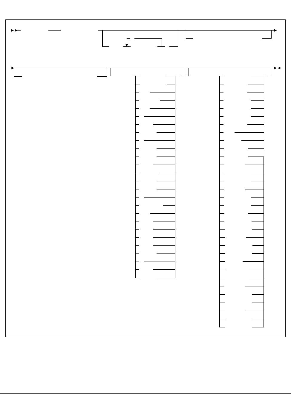
Chapter 4. Utility Functions 285
1st ed., 6/30/04 - 312579601
Syntax
Utility Name
SCREdist
specifies that a scratch redistribution is to be performed.
SCREdist ACS(acs-id)
LSM( lsm-list
,
)
SUBpool(subpool-name)
BALtol(tolerance-value)LONGItud
Standard
CST
MEDIA1
STD
1
3480
ECART
E
ECCST
ETAPE
Long
MEDIA2
3490E
ZCART
Z
HELical
DD3
DD3A
DD3B
DD3C
STK1
STK1R
R
LONGItud
18track
36track
36Atrack
36Btrack
36Ctrack
) )RECtech(MEDia(
HELical
DD3
STK1R
STK1R34
STK1R35
STK2
STK2P
STK1RA
STK1RA34
STK1RA35
STK1RB
STK1RB34
STK1RB35
STK2PA
STK1RAB
STK1RAB4
STK1RAB5
STK1RC
STK1RC34
STK1RC35
STK2P
STK2P34
STK2P35
STK2PB
STK2PA34
STK2PA35
STK2PB34
STK2PB35
Scratch Redistribution

286 VM/HSC 6.0 System Programmer’s Guide
1st ed., 6/30/04 - 312579601
Parameters
ACS
specifies one ACS in the library in which the scratch volumes are to be redistributed.
(acs-id)
identifies the ACS. The one or two digit hexadecimal ACS identifier.
LSM
optionally, specifies that only certain LSMs within an ACS are to contain scratch
cartridges (if not specified, scratch volumes are redistributed across all LSMs in the
ACS).
(lsm-list)
lsm-list can be a single LSMid or a list of LSMids. An LSM range is not
allowed. An LSMid (lsm-id) is made up of the ACSid (hexadecimal 00-FF) and
the LSM number (hexadecimal 00-17) separated by a colon (:).
The element(s) contained in an lsm-list must be enclosed in parentheses;
multiple elements must be separated by blanks or commas.
SUBpool
optionally, specifies the subpool name from which scratch volumes are to be
redistributed.
(subpool-name)
subpool-name identifies the subpool.
BALtol
optionally, specifies a balance tolerance value. Scratch volumes are distributed based
on this specified value.
(tolerance-value)
tolerance-value specifies a percent value that identifies when cartridge
redistribution ends. Valid values are 1 through 999, where the values indicate a
percentage from .1 to 99.9 (i.e., 1 signifies .1 percent; 999 equals 99.9 percent).
The initial value for the HSC is 1. If tolerance-value is not specified in this
utility, HSC uses the initial value for scratch redistribution.
The utility finishes redistributing scratch cartridges when the percentage of
scratch tapes in all specified LSMs is within tolerance-value / 2 percentage
points of each LSM’s percentage of cells in the ACS.
For example, assume an ACS has one 4410 LSM with 5,000 cells, one 9360
(WolfCreek) LSM with 1,000 cells, and 600 total scratch tapes in the ACS.
Scratch Redistribution attempts to put 500 scratches in the 4410 and 100
scratches in the 9360.
Entering BALtol(100) specifies a setting of 10 percent, which means that the
utility ends when all LSMs are within ±5 percent of the expected number of
scratches for each LSM (500 for the 4410, 100 for the 9360).
Scratch Redistribution

Chapter 4. Utility Functions 287
1st ed., 6/30/04 - 312579601
The expected number can be determined as follows:
where:
expnumlsm
expected number of scratches for each LSM.
totscracs
total number of scratches in the ACS.
totcellslsm
total number of cells in the LSM.
totcellsacs
total number of cells in the ACS.
In the previous example, the 4410 should have a range 470-530 scratches and
the 9360 a range of 70-130. To determine the BALtol range
where:
BALtol range
range of balance tolerance value.
expnumlsm
expected number of scratches for each LSM (see above).
baltol
user-supplied percent value (tolerance-value) that specifies when scratch
cartridge redistribution ends.
totscracs
total number of scratches in the ACS.
MEDia
optionally, specifies the type of cartridge to redistribute across the ACS.
Note: The SL8500 library supports only the T9x40 (9840/T9840B/T9840C and
T9940A/T9940B) media types and recording techniques.
Valid media types are:
expnumlsm = totscracs totcellslsm
totcellsacs
*
BALtol range = expnumlsm +
-baltol / 1000 totscracs
*
2
Scratch Redistribution

288 VM/HSC 6.0 System Programmer’s Guide
1st ed., 6/30/04 - 312579601
LONGItud
indicates any Standard, ECART, or ZCART cartridge.
Standard
indicates a standard length, 3480 cartridge. It can be read on any longitudinal
drives (4480, 4490, 9490, or 9490EE). Data can be written in 36-track mode on
4490, 9490, or 9490EE transports but cannot be read on an 18-track (4480)
drive. Synonyms for this type of cartridge include:
• CST
•MEDIA1
• STD
•1
• 3480
ECART
indicates a 3490E, extended capacity cartridge. It can be used only on a
36-track drive (4490, 9490, or 9490EE). Synonyms include:
•E
• ECCST
• ETAPE
• Long
•MEDIA2
• 3490E
ZCART
indicates a 3490E, extended capacity cartridge that provides greater storage
capacity than an ECART. It can be used only on a 9490EE drive.
ZCART can be abbreviated as Z.
DD3
indicates any DD3A, DD3B, or DD3C cartridge.
HELical
is a synonym for DD3.
DD3A, DD3B, DD3C
indicates a helical cartridge. The media indicator in the external label is
encoded with the cartridge type (A, B, or C).
Note: DD3A, DD3B, or DD3C can be abbreviated to A, B, or C respectively.
Types of helical cartridges, along with their associated media capacities, are:
•A - 10GB
•B - 25GB
• C - 50GB.
Scratch Redistribution
Chapter 4. Utility Functions 289
1st ed., 6/30/04 - 312579601
Data capacity differences between DD3A, DD3B, and DD3C cartridges are
related to the length of the tape in the cartridge, not to the recording density of
the data.
STK1
indicates any T9840 cartridge.
STK1R
indicates a T9840 20GB data cartridge. The media indicator in the external
label is encoded with the cartridge type (R). STK1R can be abbreviated to R.
STK2
indicates any T9940 cartridge. This parameter is the default for all T9940A and
T9940B data cartridge types.
STK2P
indicates a T9940 data cartridge. The media indicator in the external label is
encoded with the cartridge type (P).
Note: STK2P can be abbreviated to P.
T9940 cartridge media capacities are 60GB (T9940A) or 200GB (T9940B).
RECtech
optionally, specifies the method used to record data tracks on the tape surface.
Note: The SL8500 library supports only the T9x40 (9840/T9840B/T9840C and
T9940A/T9940B) media types and recording techniques.
Valid recording techniques are:
LONGItud
indicates any device that uses longitudinal recording.
18track
indicates a 4480 transport.
36track
indicates a 4490, 9490, or 9490EE transport (any device that records in 36-track
mode).
36Atrack
indicates a 4490 (Silverton) transport.
36Btrack
indicates a 9490 (Timberline) transport.
36Ctrack
indicates a 9490EE transport.
Scratch Redistribution

290 VM/HSC 6.0 System Programmer’s Guide
1st ed., 6/30/04 - 312579601
HELical
indicates a device using helical recording.
DD3
indicates a device using helical recording.
STK1R
indicates any 9840 or T9840B transport.
STK1R34
indicates any 3490E-image 9840 or T9840B transport.
STK1R35
indicates any 3590-image 9840 or T9840B transport.
STK1RA
indicates a 3490E or 3590-image 9840 transport.
STK1RA34
indicates a 3490E-image 9840 transport.
STK1RA35
indicates a 3590-image 9840 transport.
STK1RB
indicates a 3490E or 3590-image T9840B transport.
STK1RB34
indicates a 3490E-image T9840B transport.
STK1RB35
indicates a 3590-image T9840B transport.
STK1RAB
indicates a 3490E or 3590-image T9840A or T9840B transport.
STK1RAB4
indicates a 3490E-image T9840A or T9840B transport.
STK1RAB5
indicates a 3590E-image T9840A or T9840B transport.
STK1RC
indicates a 3490E or 3590-image T9840C transport.
STK1RC34
indicates a 3490-image T9840C transport.
STK1RC35
indicates a 3590-image T9840C transport.
Scratch Redistribution

Chapter 4. Utility Functions 291
1st ed., 6/30/04 - 312579601
STK2P
indicates any T9940A transport.
STK2P34
indicates a 3490E-image T9940A transport.
STK2P35
indicates a 3590-image T9940A transport.
STK2PA
indicates a T9940A transport.
STK2PA34
indicates a 3490E-image T9940A transport.
STK2PA35
indicates a 3590-image T9940A transport.
STK2PB
indicates a T9940B transport.
STK2PB34
indicates a 3490E-image T9940B transport.
STK2PB35
indicates a 3590-image T9940B transport.
Note: If RECtech is not specified, the next scratch cartridge is selected depending on
the MEDia type that has been specified.
Scratch Redistribution

292 VM/HSC 6.0 System Programmer’s Guide
1st ed., 6/30/04 - 312579601
JCL Requirements
The following definitions apply to Scratch Redistribution utility JCL:
SLSPRINT
output messages from the utility.
SLSIN
input to the utility in the form of control statement card images.
Invoking the Scratch Redistribution Utility
The easiest way to run utilities is to execute the ACS UTIL exec by entering the following
command:
EXEC ACS UTIL SCREDIST
Execution of the statement results in the ACSUTIL SLKJCL file:
ACSUTIL SLKJCL File
To execute the utility:
1. Delete the lines in the template that are not required, or leave the comment indicator
(*) in column one.
2. Remove the comment indicator from the desired lines.
3. Specify values for the desired parameters.
4. Delete the parameters that are not desired.
5. Enter the command ‘‘FILE.’’
The job file is then submitted to the ACS service machine for execution.
JCL Examples
The following example shows JCL for redistributing scratch volumes within all LSMs in
an ACS.
/JOB jobname SLUADMIN
/PARM MIXED
/FILE SLSPRINT DEV PRNT CLASS A
/FILE SLSIN *
* SCREDIST ACS(acsid) LSM(lsm!list)
Scratch Redistribution

Chapter 4. Utility Functions 293
1st ed., 6/30/04 - 312579601
JCL to Perform Scratch Redistribution
The following example shows JCL for redistributing 36-track scratch volumes within all
LSMs in ACS 00.
JCL to Perform Scratch Redistribution
The following example shows JCL for redistributing helical DD3A (10GB) scratch
volumes within LSM 01 in ACS 01.
JCL to Perform Scratch Redistribution
/JOB jobname SLUADMIN
/PARM MIXED
/FILE SLSPRINT DEV PRNT CLASS A
/FILE SLSIN *
SCREDIST ACS(01)
/JOB jobname SLUADMIN
/PARM MIXED
/FILE SLSPRINT DEV PRNT CLASS A
/FILE SLSIN
SCREDIST ACS(00) MEDIA(STD) RECTECH(36)
/JOB jobname SLUADMIN
/PARM MIXED
/FILE SLSPRINT DEV PRNT CLASS A
/FILE SLSIN *
SCREDIST ACS(01) LSM(01) MEDIA(DD3A)
Scratch Redistribution

294 VM/HSC 6.0 System Programmer’s Guide
1st ed., 6/30/04 - 312579601
Output Description
Output occurring from execution of the Scratch Redistribution utility includes:
• updated library control data set reflecting the redistribution of scratch volumes
• messages detailing actions or attempts to provide an even distribution of scratch
volumes across LSMs in an ACS (see Figure 18).
SLUADMIN (n.n.n) StorageTek Automated Cartridge System Utility PAGE 0001
TIME hh:mm:ss Control Card Image Listing DATE yyyy-mm-dd
SCREDIST ACS(00) LSM(03)
SLUADMIN (n.n.n) StorageTek Automated Cartridge System Utility PAGE 0002
TIME hh:mm:ss Scratch Redistribution DATE yyyy-mm-dd
SLS0244I Scratch Redistribution completed successfully for ACS 00
SLS0155I Condition code for utility function is 0
Figure 18. Scratch Redistribution Utility Sample Output
Scratch Redistribution
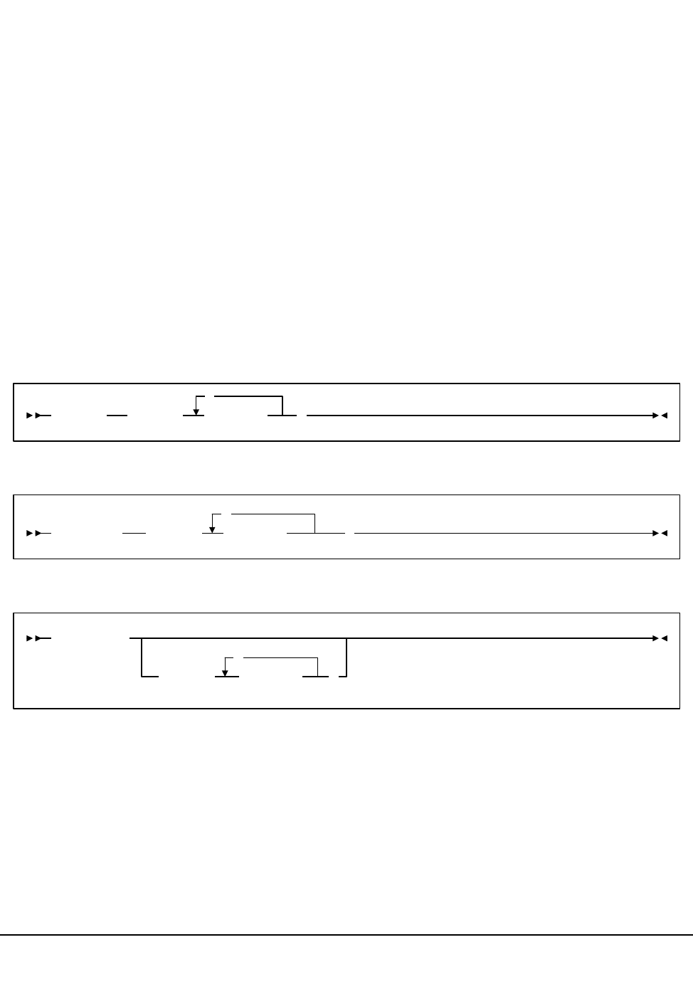
Chapter 4. Utility Functions 295
1st ed., 6/30/04 - 312579601
Scratch Update Utilities
Scratch Update utilities provide three basic functions:
• SCRAtch utility — allows you to scratch a volume, a list of volumes, or a range of
volumes
• UNSCratch utility — allows you to unscratch a volume, a list of volumes, or a range
of volumes. The entire scratch list in the library control data set can be deleted by
using the UNSCratch utility.
• REPLace utility — allows you to clear the entire scratch list and then add a volume,
a list of volumes, or a range of volumes to the scratch list(s) in the library control
data set. When using the Replace utility, additions to the scratch list(s) are made
after an initial clearing of the scratch list(s).
StorageTek customers are responsible for creating HSC scratch utility statements to
synchronize TMS and HSC scratch population definitions.
Syntax
SCRAtch utility
UNSCratch utility
REPLace utility
Utility Names
SCRAtch
specifies that scratch list additions are to be made in the library control data set.
UNSCratch
specifies that scratch list deletions are to be made in the library control data set.
REPLaceall
specifies that all scratch lists in the control data sets are to be cleared.
SCRAtch VOLser( vol-list
,
)
UNSCratch VOLser( vol-list
,
)
REPLaceall
VOLser( vol-list
,
)
Scratch Update

296 VM/HSC 6.0 System Programmer’s Guide
1st ed., 6/30/04 - 312579601
Parameters
VOLser
specifies the list of volume serial numbers to be added, deleted, or replaced in the
scratch list(s).
(vol-list)
vol-list specifies the volume serial numbers; this can be a single volume, a list
of volume serial numbers, ranges of volume serial numbers, or combinations of
lists with ranges delimited by commas. The entire list must be enclosed in
parentheses.
JCL Requirements
The following definitions apply to the Scratch Update utilities JCL:
SLSPRINT
output from the utility program.
SLSIN
input to the utility in the form of control cards.
Invoking the Scratch Update Utilities
The easiest way to run utilities is to execute the ACS UTIL exec by entering one of the
following commands:
EXEC ACS UTIL SCRAtch
EXEC ACS UTIL UNSCratch
EXEC ACS UTIL REPLaceall
EXEC ACS UTIL SCRAtch UNSCratch REPLaceall
Execution of this last statement results in the following ACSUTIL SLKJCL file:
ACSUTIL SLKJCL File
/JOB jobname SLUADMIN
/PARM MIXED
/FILE SLSPRINT DEV PRNT CLASS A
/FILE SLSIN *
* SCRATCH VOLSER(vol-list)
* UNSCRATCH(vol-list)
* REPLACEALL VOLSER(vol-list)
Scratch Update

Chapter 4. Utility Functions 297
1st ed., 6/30/04 - 312579601
To execute the utility:
1. Delete the lines in the template that are not required, or leave the comment indicator
(*) in column one.
2. Remove the comment indicator from the desired lines.
3. Specify values for the desired parameters.
4. Delete the parameters that are not desired.
5. Enter the command ‘‘FILE.’’
The job file is then submitted to the ACS service machine for execution.
JCL Example
The following example shows JCL for scratching cartridges and the alternatives of
unscratching cartridges or clearing the scratch lists in the control data set.
JCL to Scratch, Unscratch, and Replace
Output Description
Output resulting from the execution of the Scratch Update utilities includes:
• a listing of input commands with appropriate messages when syntax errors occur
• messages indicating any errors encountered during execution of the utility (see
Figure 19 on page 298)
• messages indicating successful scratching or unscratching of specific volumes
• an update to the library control data set reflecting volumes added to or deleted from
the scratch lists, or that scratch lists have been cleared or replaced.
/JOB jobname SLUADMIN
/PARM MIXED
/FILE SLSPRINT DEV PRNT CLASS A
/FILE SLSIN *
SCRATCH VOLSER(102412,102414,VACANT)
UNSCRATCH VOLSER(A1B1C1,A1B1C2,A1B1C3,A1B1C4)
REPLACEALL VOLSER(A1B1C1-A1B1C4)
Scratch Update

298 VM/HSC 6.0 System Programmer’s Guide
1st ed., 6/30/04 - 312579601
SLUADMIN (n.n.n) StorageTek Automated Cartridge System Utility PAGE 0001
TIME hh:mm:ss Control Card Image Listing DATE yyyy-mm-dd
SCRATCH VOL(102412,102414)
SLUADMIN (n.n.n) StorageTek Automated Cartridge System Utility PAGE 0002
TIME hh:mm:ss Scratch Update DATE yyyy-mm-dd
SLS0167I Volume 102412 successfully added to library as scratch
SLS0164I Volume 102414 already defined in library as scratch
SLS0155I Condition code for utility function is 4
Figure 19. Scratch Update Utilities Sample Output
Scratch Update

Chapter 4. Utility Functions 299
1st ed., 6/30/04 - 312579601
SET Utility
The SET utility allows you to change certain library configuration information without
performing reconfiguration on the library. The utility performs operations directly on the
control data set, without requiring the HSC to be active.
In many cases, the SET function may run with an active HSC. In most such cases,
changes made are not effective until the HSC has been brought down and then reactivated.
Exceptions include:
• SET FREEZE(ON|OFf), where frozen or unfrozen panels are recognized
immediately by all active HSCs.
• SET NEWHOST(newhost), where the new host will be ready to be brought online to
the HSC.
In other cases, the SET function requires that the HSC on a specific system be shut down,
or that all HSCs be shut down. This means that the heartbeat record indicates that the host
is not active, which can be achieved via the SCP STOP command. Table 14 on page 300
shows whether affected HSCs and all other HSCs can be active for each SET option.
Further information can be found in each individual option description.
Set

300 VM/HSC 6.0 System Programmer’s Guide
1st ed., 6/30/04 - 312579601
If a host has abended, the active flag is left on. If the host cannot be restarted and ended
normally, use the SET HSCLEVEL utility to reset the active flag.
How the SET Utility Functions
One of the facilities provided by the SET utility is to change the RESERVE QNAME that
was defined during LIBGEN and stored in the CDS. The RESERVE QNAME is used by
the HSC and utilities running on each host to ensure that access to the CDS is serialized.
The SET utility and HSC use an additional StorageTek-defined RESERVE QNAME to
maintain serialization while the customer-defined RESERVE QNAME is being changed.
The SET utility issues two RESERVEs against the CDS prior to an update, consisting of:
• A RESERVE with the StorageTek-defined QNAME ‘‘STKENQNM’’
• A RESERVE using the existing customer-defined QNAME (or the default value of
‘‘STKALSQN’’).
Table 14. HSC State to Run SET Options
SET Option Affected HSCs All Other HSCs
ACSDRV Down Active
CLNPRFX Down Down
COMPRFX Active Active
DELDISP Active Active
EJCTPAS Active Active
FREEZE Active Active
HOSTID Down Active
HSCLEVEL Down Active
MAJNAME Down Down
NEWHOST Active Active
NNLBDRV Down Active
SCRLABL Active Active
SLIDRIVS Down*
* In some cases, the SLIDRIVS parameter can be run effectively with the HSC ac-
tive. Refer to “Running SET SLIDRIVS With the HSC Active” on page 313 for
more details.
Down *
SLISTATN Down Active
SMF Active Active
TCHNIQE Down Down
Set

Chapter 4. Utility Functions 301
1st ed., 6/30/04 - 312579601
When the HSC is started on any host, it initially serializes on the CDS using the
StorageTek-defined QNAME. This prevents the HSC from being started while the
customer-defined QNAME is potentially in the process of being changed. If this is
successful (no SET utility in progress), the customer-defined QNAME is read from the
CDS and is used for future serialization requests.
The SET utility does not perform changes that require the structure of the database to be
changed. This includes number of hosts
• number of ACSs
• number of LSMs
• panel types.
Considerations Before Running the SET Utility
It is advisable to back up the CDS before running the utility. Note that this utility does not
update the journals. After running the utility, a backup should be performed. Otherwise, a
restore removes the changes made, and the SET utility must be rerun.
This utility does not in any way change the LIBGEN macros and does not update the
journals. Either manually edit the LIBGEN macros to change them to match the SET
changes or run the Database Decompile utility to create a new LIBGEN database (refer to
the “Database Decompile (LIBGEN) Utility” on page 225).
Access to the SET utility can be restricted by the SCP AUTHorize command. The SET
utility must be invoked when the SLUADMIN program is executed by an authorized Job
Reader; that is, one STARTed with the program AUTHRDR. The load module invoked by
SET is SLUSET.
Summary of SET Utility Options
Table 15 provides a summary of the options available for the SET utility.
Note: You can enter only one option in each SET statement. However, you can specify
multiple SET statements within a single execution of the utility. Refer to “JCL Examples”
on page 318 for an example showing multiple SET statements.
Set

302 VM/HSC 6.0 System Programmer’s Guide
1st ed., 6/30/04 - 312579601
Table 15. SET Utility Options
SET Option SET Utility Function and Location of Description
ACSDRV “SET ACS Esoteric” on page 304
CLNPRFX “SET Cleaning Prefix” on page 305
COMPRFX “SET HSC Command Prefix” on page 305
DELDISP “SET Delete Disposition” on page 307
EJCTPAS “SET Eject Password” on page 307
FREEZE “SET Freeze Panel” on page 308
HOSTID “SET Host ID” on page 404
HSCLEVEL “SET HSC Level” on page 309
MAJNAME “SET ENQ/DEQ/RESERVE QNAME” on page 310
NEWHOST “SET New Host” on page 310
NNLBDRV “SET Nonlibrary Drive Esoteric” on page 310
SCRLABL “SET Scratch Label Type” on page 311
SLIDRIVS “SET Device Numbers for Drives” on page 311
SLISTATN “SET LMU Station Address Numbers” on page 314
SMF “SET SMF Record Type” on page 315
TCHNIQE “SET Recovery Technique” on page 315
Set
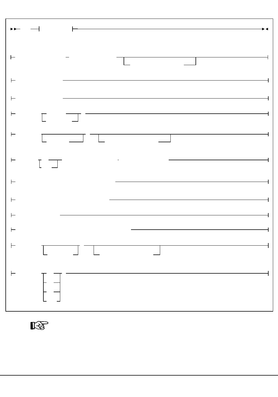
Chapter 4. Utility Functions 303
1st ed., 6/30/04 - 312579601
Syntax
Note: This syntax is continued on the next page.
SET Options
Options:
ACSDRV(esoteric),FORACS(acs-id)
,FORHOST(host-id)
CLNPRFX(prefix)
COMPRFX(cmdhex)
DELDISP( SCRTCH
NOSCRTCH
)
HOSTID (newhost),FORHOST(oldhost)
HSCLEVEL(OFF),FORHOST(host-id)
MAJNAME(qname)
FREEZE( ON )
OFf
,FORLSMID(lsm-id),FORPANEL(panel)
EJCTPAS(
newpswd
)
,OLDPASS(oldpswd)
NNLBDRV(
esoteric
)
,FORHOST(host-id)
SCRLABL( )SL
AL
NL
NSL
NEWHOST(newhost),LIKEHOST(model-host)
Set
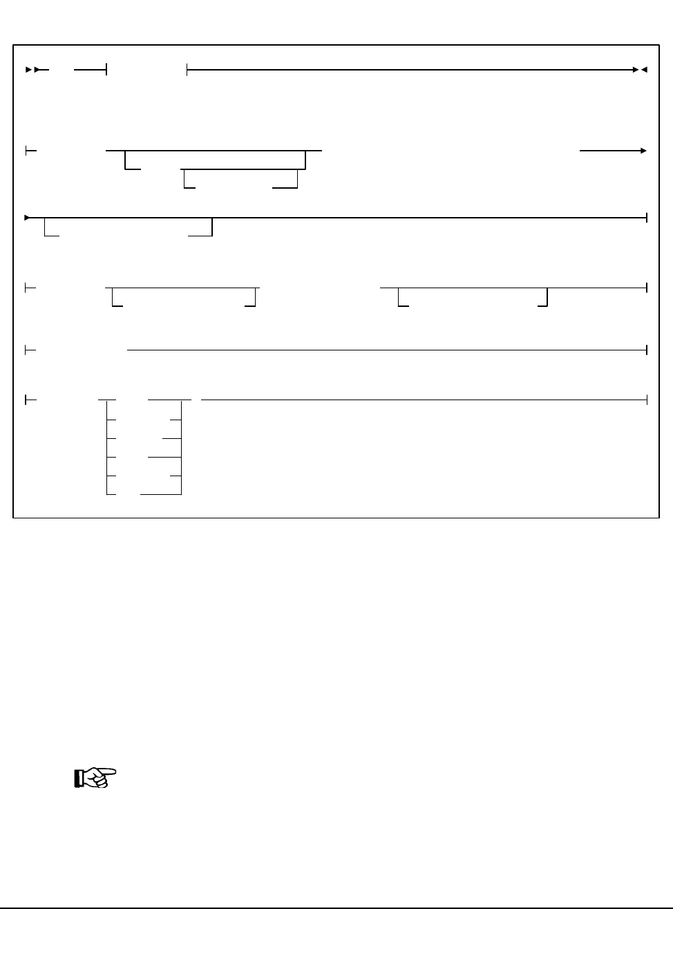
304 VM/HSC 6.0 System Programmer’s Guide
1st ed., 6/30/04 - 312579601
Syntax (continued)
Utility Name
SET
specifies that the SET function is to be invoked.
Parameters
SET ACS Esoteric
ACSDRV
specifies that the esoteric for the specified ACS is to be changed. The change does
not take effect until the relevant HSC(s) are recycled.
Note: The ACSDRV parameter has no effect in the operation of the VM/HSC. The
utility may still be used to set this parameter for MVS systems sharing this CDS.
(esoteric)
specifies a 1- to 8-character esoteric that represents all of the drives in the
specified ACS.
SET Options
Options:
SMF(libtype)
TCHNIQE(
JOURNAL
SHADOW
BOTH
STANDBY
ALL
NONE )
SLIDRIVS(
addr0
,...addr19
),FORLSMID(lsm-id),FORPANEL(panel)
,FORHOST(host-id)
SLISTATN(
stat1,...,stat16
),FORACS(acs-id)
,FORHOST(host-id)
Set

Chapter 4. Utility Functions 305
1st ed., 6/30/04 - 312579601
FORACS
specifies that the operation is being restricted to a specific ACS.
(acs-id)
specifies the ACSid whose esoteric is being changed.
FORHOST
specifies that the operation is being restricted to a specific host. Only the specified
hosts’ esoteric is set. If omitted, the esoterics for all hosts are changed.
(host-id)
specifies the 1- to 8-character host ID for the host to which the operation is
restricted.
SET Cleaning Prefix
CLNPRFX
specifies that the cleaning prefix is to be set. This parameter requires that the HSC on
all systems be shut down before changing the cleaning prefix.
(prefix)
specifies a 3-character prefix for the cleaning cartridges. Valid characters are
A-Z, 0-9, $, #, and @.
SET CLNPRFX PROCEDURE
Follow this procedure to change a cleaning cartridge prefix:
1. Eject all cleaning cartridges from all ACSs. The HSC records information about
cleaning cartridges in the CDS.
2. Terminate the HSC on all hosts.
3. Change the cleaning prefix using SET CLNPRFX.
4. Initialize the HSC on any desired hosts.
5. Enter new cleaning cartridges identified with the new prefix into all ACSs.
Note: It is preferable to enter new cleaning cartridges because a cartridge’s
select count is set to zero when it is ejected and reentered. The select count
tracks the number of times a cleaning cartridge has been used.
SET HSC Command Prefix
COMPRFX
specifies that the HSC command prefix is to be set. HSCs that were brought up
before using this function still use the old command prefix. HSCs that are brought up
after the function use the new command prefix.
(cmdhex)
specifies the 2-character hexadecimal code of the command prefix. The
characters associated with each code are shown in Table 16.
Set

306 VM/HSC 6.0 System Programmer’s Guide
1st ed., 6/30/04 - 312579601
Note: Do not assign any characters which could conflict with those in use by
CP line edit for any command-authorized virtual machines.
Table 16. Mapping of Command Prefix Codes to Characters
Hex Character Description
40 null blank
4A ¢ cent
4B . period
4C < less than
4D ( left parenthesis
4E + plus
4F | vertical bar
50 & ampersand
5A ! exclamation point
5B $ dollar sign
5C * asterisk
5D ) right parenthesis
5E ; semicolon
5F ¬ not symbol
60 - minus
61 / slash
6B , comma
6C % percent
6D _ underscore
6E > greater than
6F ? question mark
7A : colon
7B # crosshatch
7C @ at sign
7E = equals sign
7F “ double quote
Set
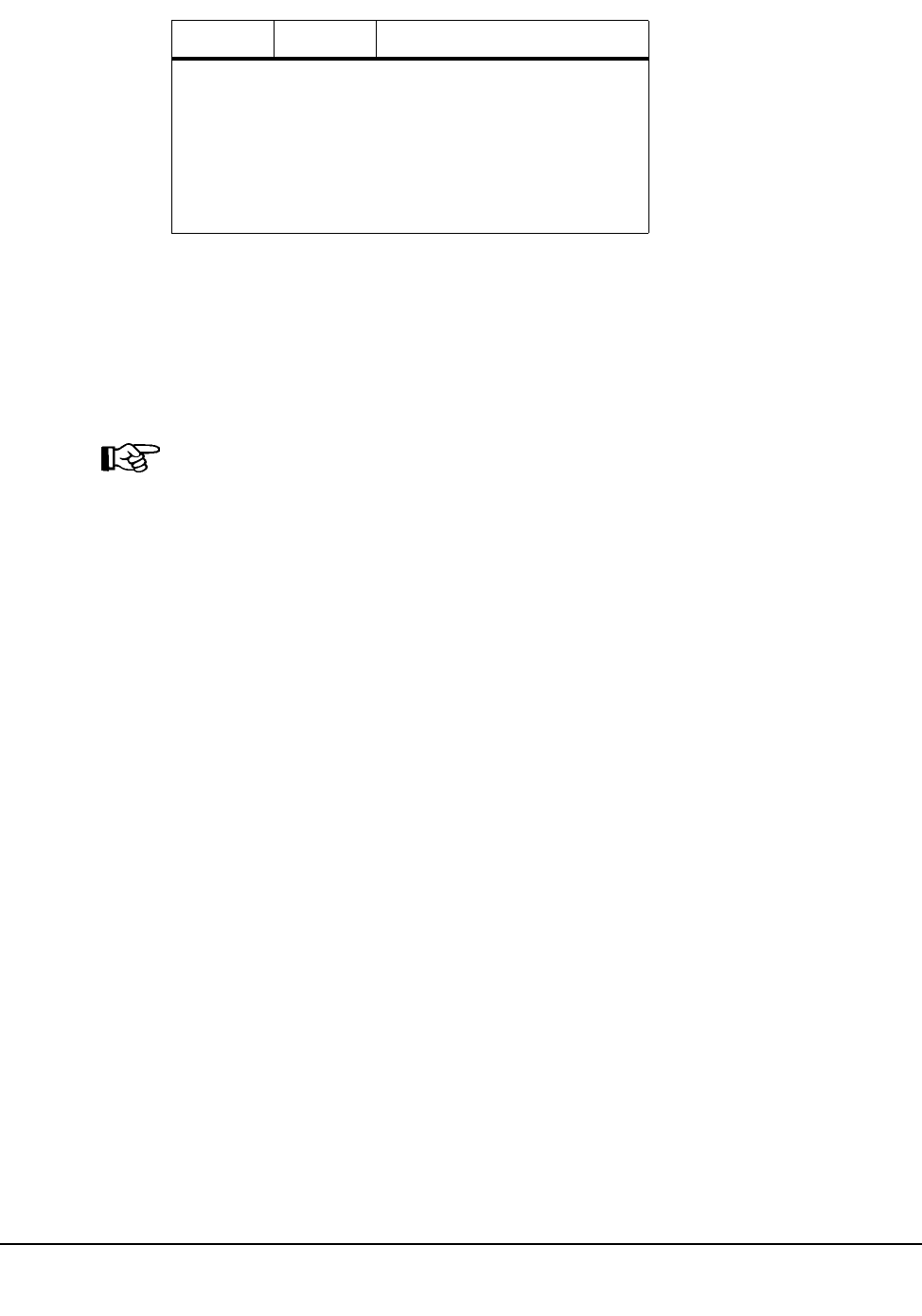
Chapter 4. Utility Functions 307
1st ed., 6/30/04 - 312579601
SET Delete Disposition
DELDISP
specifies that the delete disposition parameter is to be set. The delete disposition
parameter controls how the HSC interprets the delete disposition on a dismount
message. HSCs that were brought up before using this function still use the old delete
disposition. HSCs that are brought up after the function use the new disposition.
Note: The DELDISP parameter has no effect in the operation of the VM/HSC. The
utility may still be used to set this parameter for MVS systems sharing this CDS.
(SCRTCH)
specifies that the volume is to be placed in the scratch pool when the operating
system indicates delete disposition.
(NOSCRTCH)
specifies that delete disposition is to be ignored. Because CA-1(TMS) and
CA-DYNAM/TLMS provide a grace period, users of these products should
specify NOSCRTCH.
SET Eject Password
EJCTPAS
specifies that the eject password is to be set. HSCs that were brought up before using
this function still use the old password. HSCs that are brought up after the function
use the new password.
(newpswd)
specifies a 1- to 8-character eject password. The new password must be
alphanumeric: A-Z (capital letters only) and 0-9. If newpswd is omitted, eject
password checking is disabled. Note that the newpswd will not be displayed on
SLSPRINT.
OLDPASS
specifies that the old eject password is being specified. The old password must be
specified to change or delete a password. To delete an old password, omit it from the
syntax, i.e., OLDPASS(). If there is not currently an eject password, this parameter
can be omitted.
Note: Ensure that the prefix character used does not conflict
with any of the following:
• another subsystem’s command prefix character (such as
“*” for SCP)
• any of the CP line editing symbols in effect (such as “#,”
“@,” “¢,” or “““). Issue the CP QUERY TERM
command to determine the line editing symbols in effect.
Table 16. Mapping of Command Prefix Codes to Characters
Hex Character Description
Set

308 VM/HSC 6.0 System Programmer’s Guide
1st ed., 6/30/04 - 312579601
(oldpswd)
specifies the 1-to 8-character old eject password. Note that oldpswd is not
displayed on SLSPRINT.
SET Freeze Panel
FREEZE
specifies to disallow (freeze) or allow (unfreeze) additional cartridges to be stored on|
a panel.
Notes: Frozen or unfrozen panels are recognized immediately by all active HSCs. It|
is not necessary to stop and reinitialize active HSCs to detect changes made by SET
FREEZE.
ON
specifies to freeze a panel, which prevents additional cartridges from being
moved to it. This restriction includes allocating new cartridge locations on a
panel as a result of
• a MOVe command, utility, or PGMI request
• cartridge entry into the ACS f
• float, scratch dismount, or scratch redistribution processing.
If a cartridge on a frozen panel is selected (e.g., through a mount request), it|
may be returned to its home cell on the frozen panel after fulfilling the request.
Cartridges already located on a frozen panel must be deliberately moved off
using the MOVe command, utility, or PGMI request, or cartridges can be
ejected by running the EJECt command or EJECt utility.
OFf
specifies to unfreeze a panel, which allows additional cartridges to be moved to
it.
Note: On a frozen panel, if a panel type is changed by running the Reconfiguration
utility, the new panel is not frozen. If the panel type did not change, the panel remains
frozen after a reconfiguration.
Set
Chapter 4. Utility Functions 309
1st ed., 6/30/04 - 312579601
SET Host ID
HOSTID
specifies that the old host ID is being changed to a new name.
(newhost)
specifies a 1- to 4-character host ID which also serves and the SMF system ID.
This host ID must also be specified by the LIBSUBSYS parameter in the ACS
SYSPROF file. newhost cannot already be defined in the CDS.
FORHOST
specifies the old host ID.
(oldhost)
specifies a 1-to 8-character host ID. This host must not be marked active in the
CDS. An HSC can be down but still marked active. SET HOSTID would fail to
run. To be marked inactive, the HSC, in the host that is down, must be brought
up and then shut down. Also, another host could perform cross-host recovery on
the HSC that is down, but marked active. Either of these change the status in the
CDS of the down HSC from active to inactive. See “SET HSC Level” on page
309 for information about resetting operating flags.
Note: You must delimit the HOSTID (newhost or oldhost) with quotes when
this ID is in lower case (such as Cray station users).
SET HSC Level
HSCLEVEL
specifies that the HSC active and release level indicators are to be cleared for the
designated host.
Notes: If used, HSCLEVEL should be performed only when the host designated in
host-id is inactive.
These indicators remain set after an abrupt termination of the HSC has occurred (e.g.,
a cancellation of the HSC or a crash of the operating system).
(OFF)
specifies that the HSC active and HSC release level indicators for the
designated host are to be cleared.
FORHOST
specifies that the active indicators are to be cleared for the designated host.
(host-id)
specifies the 1- to 8-character host ID of the host to which the operation is
restricted.
Note: StorageTek recommends the following alternatives to executing SET
HSCLEVEL because they reset the HSC indicators and recover resources owned by
the failing host:
Set

310 VM/HSC 6.0 System Programmer’s Guide
1st ed., 6/30/04 - 312579601
• Restart the HSC on the host.
• Enter the RECover host-id FORCE operator command.
SET ENQ/DEQ/RESERVE QNAME
MAJNAME
specifies that the ENQ/DEQ/RESERVE QNAME is to be set This parameter
requires that the HSC on all systems be shut down before changing the QNAME.
(qname)
specifies a 1- to 8-character QNAME. The QNAME is blank padded on the
right. The name should conform to the requirements for a QNAME. If any hosts
are MVS hosts, to prevent conflicts with the operating system, the QNAME
should not start with ‘‘SYSA’’ through ‘‘SYSZ.’’ Since the HSC is authorized,
the ‘‘SYSA’’ through ‘‘SYSZ’’ names would be allowed, but deadlock may
result.
SET New Host
NEWHOST
specifies that a new host is to be added. The new host to be added cannot exceed the
maximum limitation of 16 hosts.
(newhost)
specifies a 1- to 8-character host ID which also serves as the SMF system ID for
JES2 or the main processor name for JES3. newhost cannot already be defined
in the CDS.
Note: You must delimit the HOSTID with quotes when this ID is in lower case.
LIKEHOST
specifies that an existing configuration, as currently defined in the LIBGEN, is to be
used for the new host. Settings used include:
• SLILIBRY NNLBDRV (nonlibrary drive esoteric)
• SLIACS ACSDRV (ACS drive esoteric)
• SLISTATN ADDRESS (ACS 3270 station addresses)
• SLIDRIVS ADDRESS (drive addresses).
(model-host)
specifies a 1- to 8-character host ID.
SET Nonlibrary Drive Esoteric
NNLBDRV
specifies that the nonlibrary drive esoteric is being set. The change does not take
effect until the relevant HSC(s) is(are) recycled. A relevant HSC is one that resides
in the host specified in FORHOST. If FORHOST is omitted, all HSCs are relevant
because the operation is not restricted to a specific host.
Set

Chapter 4. Utility Functions 311
1st ed., 6/30/04 - 312579601
Note: The NNLBDRV parameter has no effect in the operation of the VM/HSC. The
utility may still be used to set this parameter for MVS systems sharing this CDS.
(esoteric)
specifies a 1-to 8-character esoteric. If the value is omitted, this means that
there are no nonlibrary drives installed.
FORHOST
specifies that the operation is being restricted to a specific host. Only the specified
hosts’ nonlibrary drive esoteric is to be set. If omitted, the nonlibrary esoterics for all
hosts are to be changed.
(host-id)
specifies the 1- to 8-character host ID of the host to which the operation is
restricted.
SET Scratch Label Type
SCRLABL
specifies the scratch label type is to be set. To add to the scratch pool, the
REPLaceall function is run before the Scratch Update utility. Otherwise, the scratch
update utility should be run to update the scratch pools after using this function.
(SL)
specifies that nonspecific requests for standard-labeled tapes are to be
automated.
(AL)
specifies that nonspecific requests for ANSI-labeled tapes are to be automated.
(NL)
specifies that nonspecific requests for nonlabeled tapes are to be automated.
(NSL)
specifies that nonspecific requests for nonstandard labeled tapes are to be
automated.
SET Device Numbers for Drives
SLIDRIVS
specifies that the device numbers for the drives in a particular panel are being
changed or added. The change does not take effect until the affected HSC(s) is
recycled. Refer to “Running SET SLIDRIVS With the HSC Active” on page 313 for
more information.
Caution: StorageTek recommends you bring the HSC down on all hosts before
specifying this parameter, and recycle the HSC after every SET SLIDRIVS
operation. Table 17 on page 313 describes some instances where the HSC can remain
active, however, unpredictable results can occur if the HSC is not terminated.
Set

312 VM/HSC 6.0 System Programmer’s Guide
1st ed., 6/30/04 - 312579601
(addr0,...addr19)
specifies the device numbers for the panel. The numbers are from the top of the
panel down. If a device number is omitted, this means that the host cannot
access a drive in that particular position in the panel, or the drive does not exist.
Notes:
1. Blanks as well as commas may be used to separate the drive
specifications.
2. The total number of drives specified (including comma placeholders) must
be 4, 10, 16 (for an SL8500), or 20. You cannot specify 20-drive panels on
9740 (TimberWolf) LSMs or SL8500 libraries.
3. Before this utility can be executed, all cells in the panel must be empty if
the user is moving to or from a 20-drive panel configuration.
4. The user can change a drive panel between a 4- or 10-drive panel (normal)
and a 20-drive panel (wide) without running a reconfiguration. Affected
panels must be empty and no cells in the panels can be allocated to
cartridges.
To ensure that drive panels being changed from normal to wide
configurations (or vice versa) remain empty, freeze them with the SET
FREEZE utility. Then, move all cartridges to other panels or LSMs.
If a panel type is changed by SET SLIDRIVS, the new panel will not be
frozen. Frozen panels whose panel type did not change remain frozen after
SET SLIDRIVS.
5. HSC does not allow duplicate addresses for drives. If it becomes necessary
to exchange the drive addresses on one panel with the drive addresses on
another panel, the addresses on one of the panels must first be changed to
temporary addresses that are not currently defined. For example:
LSM0, PANEL10, ADDRESSES!400,401,402,403
LSM1, PANEL11, ADDRESSES!404,405,406,407
If the 400-403 addresses are to be moved to LSM1 and 404-407 are to be
moved to LSM0, the SET utility must first be run to change the LSM0
addresses (400-403) to 900-903 (or some other addresses that are not
currently defined). The SET utility is then run to change the LSM1
addresses to 400-403. The utility is run a third time to change the
temporary LSM0 addresses (900-903) to 404-407.
6. On all LSMs, drives are defined to the HSC from top to bottom, with
addr0 representing the topmost drive and addrn the bottommost drive.
However, on a 9740 10-drive panel LSM, the drives are populated and
configured to the 9740 LSM from bottom to top. (9740 4-drive panels are
configured to the 9740 LSM from top to bottom, as are all other LSM
drive panels.)
Set
Chapter 4. Utility Functions 313
1st ed., 6/30/04 - 312579601
An example showing how to define a 9740 10-drive panel containing five
9840 drives i
SET SLIDRIVS(,,,,,BD4,BD3,BD2,BD1,BD0),FORLSMID(lsm!id),
FORPANEL(panel)
FORLSMID
specifies that the operation is being restricted to a specific LSM.
(lsm-id)
specifies the LSMid containing the drive panel whose addresses are being
changed. An LSMid is made up of the ACSid (hexadecimal 00-FF) and the
LSM number (hexadecimal 00-17) separated by a colon (:).
FORPANEL
specifies that the operation is being restricted to a specific panel.
(panel)
specifies the 2-digit ID of the panel containing the drives whose addresses are
being changed.
Note: The specified panel must be an existing drive panel in the LSM.
FORHOST
specifies that the operation is being restricted to a specific host. Only the specified
hosts’ drive device numbers are set. If omitted, the device numbers for all hosts are
changed.
Note: The number of drive positions for a specific host must equal the number of
drive positions defined globally (issuing SET SLIDRIVS without the FORHOST
parameter).
(host-id)
specifies the 1- to 8-character host ID of the host, to which the operation is
restricted.
Running SET SLIDRIVS With the HSC Active
Ideally, the HSC should be shut down on all hosts when you specify this parameter. In
some cases, however, the HSC can be left active without causing adverse results. Table 17
defines options for running SET SLIDRIVS.
Table 17. HSC State/SET SLIDRIVS Operation
HSC State Effect on SET SLIDRIVS
Down If the HSC is down on all hosts, the HSC recognizes all new drive
locations when it is initialized. Shutting the HSC down ensures
that accurate drive information is written to the CDS.
Active The HSC can be up on all hosts only if new drives are being added
at new drive locations. The HSC recognizes the new drive
locations when it is recycled on a host.
Set
314 VM/HSC 6.0 System Programmer’s Guide
1st ed., 6/30/04 - 312579601
SET SLIDRIVS Procedure
The following procedure shows one method for changing unit addresses with the HSC
active.
• For one host:
1. Modify the affected LSM offline (MODify lsm-id OFFline). The LSM will be
offline to all hosts.
2. Use SET SLIDRIVS to update the CDS drive records while the StorageTek
CSE(s) is making the hardware changes.
3. Recycle the HSC on one host.
4. Vary the affected ACS offline (Vary ACS(acs-id) OFFline) on all hosts running
an HSC that has not been recycled.
5. Modify the affected LSM online (MODify lsm-id ONline). The LSM will be |
online to all hosts where the ACS is online.
Note: Only hosts that are online to the ACS and that are running a recycled
HSC will mount to drives connected to this LSM.
• For the remaining hosts, recycle the HSC, and the affected ACS will come up.
SET LMU Station Address Numbers
SLISTATN
specifies that the LMU station addresses are to be set. The change does not take
effect until the affected HSC(s) is recycled. An affected HSC is one that resides in
the host specified in FORHOST. If FORHOST is omitted, all HSCs are relevant
because the operation is not restricted to a specific host.
(stat1,...,stat16)
specifies the LMU station addresses associated with a particular ACS. No |
station addresses are required. Up to 16 can be specified, separated by commas
Notes:
1. When adding one or more station addresses to an existing list of stations,
you must specify all old stations as well as new ones. Any stations (for this
Active If unit addresses are changed or deleted for an existing drive
location, either
• the affected LSM must be offline until the HSC has been
recycled on all hosts, or
• the affected ACS must be offline to all affected hosts that access
an HSC that has not been recycled.
Table 17. HSC State/SET SLIDRIVS Operation
HSC State Effect on SET SLIDRIVS
Set

Chapter 4. Utility Functions 315
1st ed., 6/30/04 - 312579601
ACS and Host ID) not specified here will be deleted and no longer
available for use.
2. To remove station addresses for an ACS or host, do not specify station
addresses following the SLISTATN parameter. For example
SET SLISTATN(),FORACS(#1),FORHOST(HSCA)
FORACS
specifies the ACS for which station addresses are being changed. (acs-id) specifies
the ACSid whose stations are being changed (00 - FF).
FORHOST
specifies that the operation is being restricted to a specific host. Only the specified
hosts’ stations are set. If omitted, the stations for all hosts are changed.
(host-id)
specifies the 1- to 8-character host ID for the host to which the operation is
restricted.
SET SMF Record Type
SMF
specifies that the SMF record type used by the HSC is to be set. Until the HSC is
brought down and back up on all CPUs, the Activities Report utility produces
incorrect results. This is because some HSCs are writing records with the old SMF
record type, and some with the new record type.
(libtype)
specifies the SMF record type. The range is from 0 to 255, inclusive. Since 128
through 255 are for user-defined records, it is recommended that a number from
128 through 255 be chosen, and that the number does not conflict with other
user-defined record types.
SET Recovery Technique
TCHNIQE
specifies that the control data set recovery technique is to be set. This SET utility
replaces the recovery technique that is currently defined in the CDS. Refer to
‘‘SLIRCVRY Macro’’ in the HSC Installation Guide for a complete description of
the LIBGEN SLIRCVRY macro. A recovery technique value must be specified;
there is no default value.
NONE
specifies no form of recovery is used for the control data set. Thus, the primary
control data set must be rebuilt, if inaccessible.
JOURNAL
specifies that there is to be only one primary control data set and that journals
are kept. These data sets are to be used for recovery purposes.
Set

316 VM/HSC 6.0 System Programmer’s Guide
1st ed., 6/30/04 - 312579601
The journals contain a record of all transactions that update the control data set.
There are two journals per host. It is recommended that they are placed on
separate HDAs from the primary control data set DASD volume.
SHADOW
specifies that there is to be two distinct copies of the control data set (primary
and secondary) for recovery purposes. It is recommended that these data sets
reside on separate HDAs and separate strings. A journal is not recorded.
BOTH
specifies that two distinct copies of the control data set (primary and secondary)
and journals are specified for recovery purposes. Default is BOTH.
STANDBY
specifies that primary, secondary, and standby control data sets are to be
recorded for recovery purposes. No journals are recorded during HSC
operation.
ALL
specifies that all control data sets (primary, secondary, and standby) and
journals are to be kept and available for recovery purposes.
SET TCHNIQE PROCEDURE
Use the following procedure to invoke the TCHNIQE utility and to set the appropriate
recovery technique value:
1. ALLOCATE, based on existing CDS definitions, any new CDS copies that will be
needed for the subsequent SET recovery technique.
2. Stop the HSCs on all hosts configured to use the CDS you are intending to update
with SET recovery technique.
3. Run the BACKup utility.
4. Run the RESTore utility to restore all CDS copies required to support the current
recovery technique. If the recovery technique update in the following step requires
new CDS copies, then include them in this restore.
5. Run the SET utility with the appropriate recovery technique value. It is important to
note that the SET utility for this recovery technique update must include /FILE
statements for all CDS copies defined in either the old or the new recovery
technique.
6. Run the BACKup utility again. This backup provides you with the ability to restore
the updated CDS.
JCL Requirements
The following definitions apply to the JCL for SET utilities:
SLSPRINT
output messages from the utility program.
Set

Chapter 4. Utility Functions 317
1st ed., 6/30/04 - 312579601
SLSCNTL
the primary control data set. A primary control data set is required.
SLSCNTL2
the secondary control data set. This statement is used only if you have configured
and initiated a secondary control data set for your installation. A secondary control
data set is optional, but highly recommended.
SLSSTBY
the standby control data set. This statement is used only if you have configured and
initiated a standby control data set for your installation. SLSIN input to the utility in
the form of control cards.
Invoking the Set Utility
The easiest way to run utilities is to execute the ACS UTIL exec by entering the following
command:
EXEC ACS UTIL SET
Execution of the statement results in the ACSUTIL SLKJCL file:
ACSUTIL SLKJCL File
To execute the utility:
1. Delete the lines in the template that are not required, or leave the comment indicator
(*) in column one.
2. Remove the comment indicator from the desired lines.
3. Specify values for the desired parameters.
4. Delete the parameters that are not desired.
5. Enter the command ‘‘FILE.’’
The job file is then submitted to the ACS service machine for execution.
/JOB jobname SLUADMIN
/PARM MIXED
/FILE SLSPRINT DEV PRNT CLASS A
/FILE SLSCNTL DEV <500> DSN <dsname>
/FILE SLSCNTL2 DEV <501> DSN <dsname>
/FILE SLSSTBY DEV <vaddr> DSN <dsname>
/FILE SLSIN *
* SET COMPRFX(cmdhex)
Set
318 VM/HSC 6.0 System Programmer’s Guide
1st ed., 6/30/04 - 312579601
JCL Examples
The following example shows basic JCL that is required for executing the SET utility.
Statements that represent individual utility functions are included in the JCL, as you deem
necessary, to comprise the HSC configuration that you want to invoke.
JCL for Set Utility
Note: JCL statements for SLSCNTL2 and SLSSTBY are optional. However, if you have
configured your library to have a secondary and standby control data set, you must
include statements for these control data sets. It is highly recommended that you operate
your library with a secondary and standby control data set.
The following example shows JCL that makes these modifications:
• changes the host ID from HSCB to HSC2
• sets the library station device numbers to 0CD and 0DD for ACS 00 on host HSC2
• changes the nonlibrary drive esoteric to ‘‘CTAPE’’ for hosts CPUA and CPUB
• changes the device numbers for ACS 00 LSM 0 panel 10 on all hosts.
Notes:
1. Only one option can be specified per SET statement. This example demonstrates that
multiple SET statements can be entered for each execution of the utility.
2. In the SET SLIDRIVS statement below, note that a continuation character (+) has
been added to allow 10-drive panels to be specified on one statement.
/JOB jobname SLUADMIN
/PARM MIXED
/FILE SLSCNTL DEV vaddr DSN control.set.name
/FILE SLSCNTL2 DEV vaddr DSN secondary.set.name
/FILE SLSSTBY DEV vaddr DSN standby.set.name
/FILE SLSPRINT DEV PRNT CLASS A
/FILE SLSIN *
/* List indivual utility statements following this comment
.
.
(utility statements)
.
Set

Chapter 4. Utility Functions 319
1st ed., 6/30/04 - 312579601
JCL for Multiple SET Statements
Note: The last two lines of the JCL example above (SET NNLBDRV...) are not used by
VM, but they are valid for setting an MVS host from a VM host.
Output Description
Output resulting from the execution of the SET command includes:
• a listing of input commands with appropriate messages when syntax errors occur
• messages associated with error conditions resulting from an unsuccessful attempt to
execute SET processing
• an updated CDS with the changed parameters
• a condition code indicating successful or unsuccessful CDS update.
/JOB jobname SLUADMIN
/PARM MIXED
/FILE SLSCNTL DEV vaddr DSN control.set.name
/FILE SLSCNTL2 DEV vaddr DSN secondary.set.name
/FILE SLSPRINT DEV PRNT CLASS A
/FILE SLSIN *
SET HOSTID(HSC2) FORHOST(HSCB)
SET SLISTATN(0CD,0DD) FORACS(00) FORHOST(HSC2)
SET NNLBDRV(CTAPE) FORHOST(CPUA)
SET NNLBDRV(CTAPE) FORHOST(CPUB)
Set
320 VM/HSC 6.0 System Programmer’s Guide
1st ed., 6/30/04 - 312579601
Unselect Utility
The UNSElect utility allows you to ‘‘unselect’’ a volume that the HSC leaves in a selected
state. Usually, this is an error. The ‘‘unselect’’ operation is performed without cycling the
HSC.
Note: Use this utility only if you are certain that the HSC has incorrectly left the volume
selected. Incorrect use of this utility can result in HSC abends and errant volumes.
Issue a Display Volume DEtail command to determine which host has the volume in
question. Then, issue Display DRives and Display Requests commands on the host that
has the volume in question to see if that volume is being used.
If the selected volume is mounted on a transport, issue a DISMount command for the
transport. If there is a request active to the LMU for the volume, wait for the request to
complete. If the overdue response handler indicates the request has timed out, you may
want to abort the request.
Note: For detailed information about the Display and DISMount commands, refer to
‘‘DISPLAY Command’’ and ‘‘DISMOUNT Command’’ in the HSC Operator’s Guide.
The HSC must be running on the same host that is running the UNSElect utility. If the
selected volume is selected by another active (not marked inactive in the CDS) host, the
HSC on that host must be running. Both hosts must be connected to the same LMU. In an
environment with multiple ACSs, this can be any LMU, as long as it is the same LMU.
If the FORCE option is specified, the volume is ‘‘unselected’’ regardless of the other host
being active. Using this option can result in a greater likelihood of abends if the host is
running.
If the host running UNSElect cannot communicate because both hosts are not connected to
the same LMU, rerun UNSElect on the host with the volume selected. Do not use the
FORCE parameter in this case.
Access to the UNSElect utility can be restricted by the SCP AUTHorize command. The
UNSElect utility must be invoked when the SLUADMIN program is executed by an
authorized Job Reader; that is, one STARTed with the program AUTHRDR. The load
module invoked by UNSElect is SLUNSEL.
Syntax
UNSElect VOLser(volser)
,FORCE
Unselect

Chapter 4. Utility Functions 321
1st ed., 6/30/04 - 312579601
Utility Name
UNSElect
specifies that the UNSElect function is to be performed.
Parameters
VOLser
indicates that a VOLSER is being specified for unselection.
(volser)
volser specifies the VOLSER to be unselected.
FORCE
optionally indicates that the volume is to be unselected even if communication with
the host that has the volume selected is not possible.
JCL Requirements
The following definitions apply to UNSElect utility JCL:
SLSPRINT
output messages from the utility program.
SLSIN
input to the utility in the form of control cards.
Invoking the Unselect Utility
The easiest way to run utilities is to execute the ACS UTIL exec by entering the following
command:
EXEC ACS UTIL UNSElect
Execution of the statement results in the ACSUTIL SLKJCL file:
ACSUTIL SLKJCL File
To execute the utility:
1. Delete the lines in the template that are not required, or leave the comment indicator
(*) in column one.
2. Remove the comment indicator from the desired lines.
3. Specify values for the desired parameters
/JOB jobname SLUADMIN
/PARM MIXED
/FILE SLSPRINT DEV PRNT CLASS A
/FILE SLSIN *
* UNSELECT VOLser(volser),FORCE
Unselect

322 VM/HSC 6.0 System Programmer’s Guide
1st ed., 6/30/04 - 312579601
4. Delete the parameters that are not desired.
5. Enter the command ‘‘FILE.’’ The job file is then submitted to the ACS service
machine for execution.
JCL Example
The following example shows JCL for unselecting volume BWX119.
JCL to Unselect a Volume
Output Description
Output occurring from execution of the UNSElect utility includes:
• a listing of input commands with appropriate messages when syntax errors occur
• messages associated with error conditions resulting from an unsuccessful attempt to
execute UNSElect processing
• messages indicating actions occurring during processing (see Figure 20 on page 323)
• an updated control data set indicating the volume is unselected
• a condition code indicating successful or unsuccessful unselection (see Figure 20 on
page 323).
/JOB jobname SLUADMIN
/PARM MIXED
/FILE SLSPRINT DEV PRNT CLASS A
/FILE SLSIN *
UNSELECT VOLSER(BWX119)
Unselect

Chapter 4. Utility Functions 323
1st ed., 6/30/04 - 312579601
SLUADMIN (n.n.n) StorageTek Automated Cartridge System Utility PAGE 0001
TIME hh:mm:ss Control Card Image Listing DATE yyyy-mm-dd
UNSELECT VOL(BWX119)
SLS0376I Volume BWX119 is now unselected; owning host was HSC1
SLS0155I Condition code for utility function is 0
Figure 20. Unselect Utility Sample Output
Unselect

324 VM/HSC 6.0 System Programmer’s Guide
1st ed., 6/30/04 - 312579601
Volume Report Utility
The function of the Volume Report utility is to produce a listing of the physical location
for volumes residing in an LSM. This utility is used primarily for informational purposes
and provides history and usage statistics on specific library volumes.
The Volume Report utility program functions as a stand-alone process in batch mode and
does not require that the HSC be operational in order to execute. If the HSC is operational,
Volume Report can extract CDS and VOLATTR information from the active HSC.
In addition to the reporting capability, the utility can produce a ‘‘flat file’’ which may be
used as a data source for manipulating the data for user-defined reports with other
software products.
Note: It is recommended that a 2 megabyte region size be used when running the Volume
Report utility.
A report may be sorted or unsorted. When the SORT option is specified, volume data can
be sorted by:
• volume serial numbers
• location of volumes
• select count (usage) of volumes
• date volumes were inserted into the library control data set
• last date volumes were selected.
Sorting may be done in ascending or descending order.
• The report sorted by volume serial number is useful when a listing of library
information is needed in ascending VOLSER sequence.
• The report sorted by location can be utilized for either the mass transfer of volumes
or assessing the potential impact of a component failure. With this information, the
installation can avoid jobs which access volumes within failed components.
• The report sorted by usage lists volumes by selection count. This report is useful for
either ejecting low use volumes or replicating information on high use volumes.
The utility output may include a variety of information, depending upon the user-specified
parameters. For example, volume information can be specifically included or excluded
from a report based on:
• scratch status
• errant status
• external label status
• selected status.
Specifying of report parameters can range from the ACS or LSM level to as specific as a
single volume serial number or list of volume serial numbers. Whenever a report is
generated using library element parameters (i.e., LSM and/or ACS), the Volume Report
utility may also output messages identifying empty but allocated cells.
Volume Report

Chapter 4. Utility Functions 325
1st ed., 6/30/04 - 312579601
The volume location information in this report is accurate only up to the time that the
volume information is read from the database. For recovery purposes, a listing from a
Volume Report run, while the HSC is down on all hosts, must be used to assist locating the
required volumes.
Note: Volume movement occurs as a result of:
• mount activity, dismount activity, enter activity, or eject activity
• invoking the Scratch Redistribution utility
• invoking the MOVe command or utility.
Media Type and Recording Technique Considerations
Volume reports can display media type (MEDia) and recording technique (RECtech).
MEDia data is extracted from either the CDS volume attribute record (VAR) or the
VOLATTR statements. The VAR media information is updated when the volume external
media label is read by the robotic vision system and is transmitted back to the HSC
through the LMU. This can occur as a result of mounts, CAP enters, or audits.
RECtech is extracted from the VOLATTR statement. If the VOLATTR statement does not
contain the recording technique for the volume, or if the VOLATTR media value conflicts
with the media value that is present in the VAR, the RECtech value is Protected
determined from the MEDia value that is being reported. This RECtech value will include
all recording techniques that the reported MEDia value allows (e.g., if the media value is
Standard and the recording technique value defaults to LONGItud, then 18track, 36track,
36Atrack, 36Btrack, and 36Ctrack recording techniques also are included).
The report indicates if the VAR media type has been verified by the LMU. If the LMU
verified the media type, the VAR media value is reported. If the media type has not been
verified by the LMU, the VOLATTR MEDia value is used if it exists. If both VOLATTR
and VAR media type information do not exist, the volume is considered to be Standard. At
a minimum, a VOLATTR statement must be present for all volumes that are not Standard
cartridges. This is because:
• the vision system cannot recognize two-tone (ECART) cartridges without an external
media label
Note: It is recommended that users provide an external media label for all ECARTs.
ZCART, DD3, and STK1 media must have external labels.
• for scratch purposes, volume categorization occurs based on the media type.
Therefore, it is extremely important that accurate VOLATTRs be defined to maintain
accurate scratch counts.
Run the Volume Report utility to verify that your VOLATTR statements and the VARs are
in agreement.
To determine which volumes are mismatched between the VAR and the VOLATTR
statements, specify either INCLUDE(NONMEDEQ) or EXCLUDE(MEDEQUAL) in the
Volume Report syntax. Refer to the syntax and parameter descriptions sections of this
utility for more information.
Volume Report

326 VM/HSC 6.0 System Programmer’s Guide
1st ed., 6/30/04 - 312579601
If the VAR is not synchronized with the VOLATTR statements, one of the following
actions will resolve the mismatch.
• change the VOLATTR statement(s)
• add an external media label to cartridges that are not Standard
• mount the cartridges
• enter the cartridges through the CAP
• run an audit.
Note: If an external label is not provided for all ECARTs, the volume report may continue
to show mismatches.
Be aware that if you choose to run an audit to update the VAR, audits can be very
time-consuming and can slow HSC processing.
Volume Report
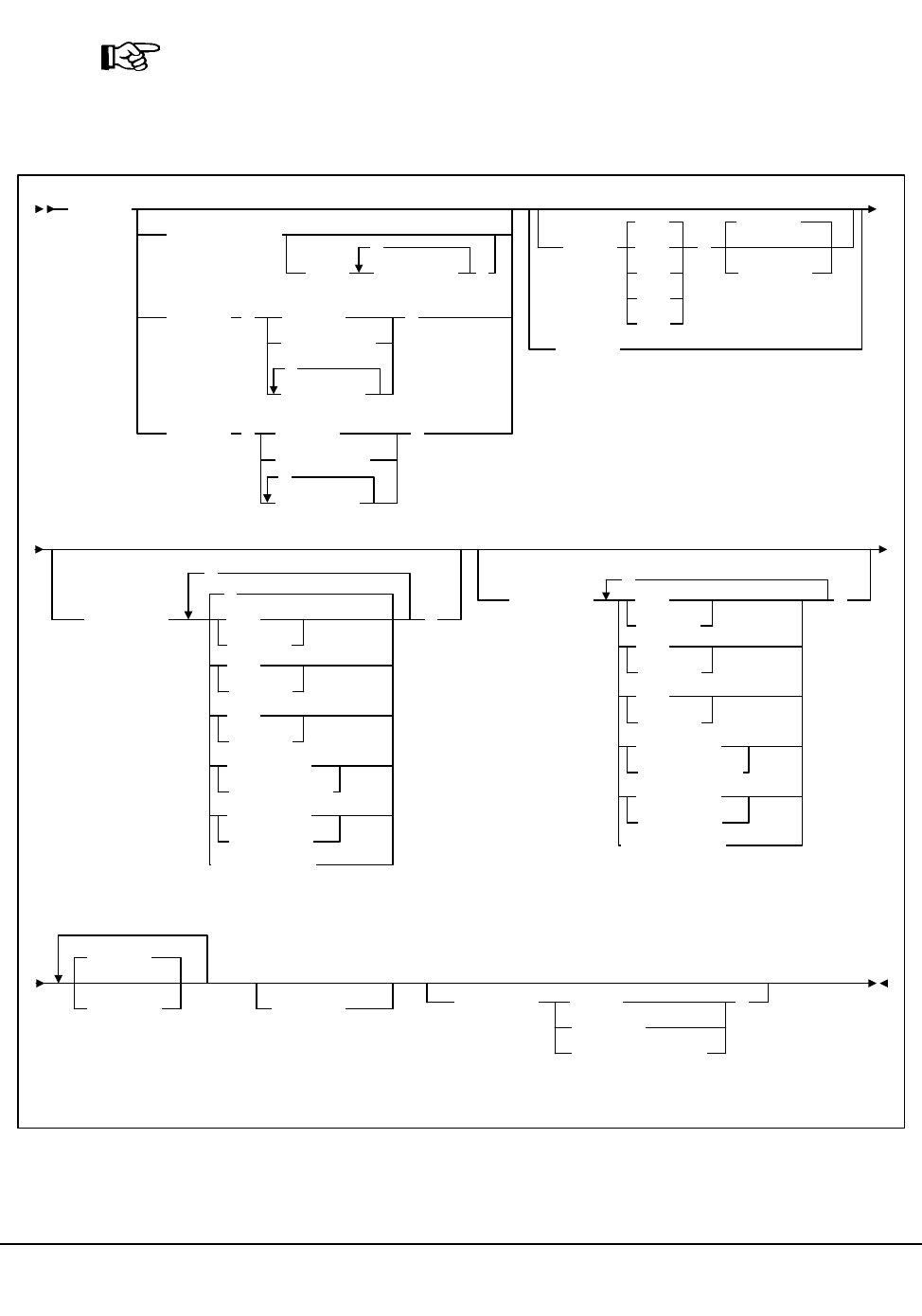
Chapter 4. Utility Functions 327
1st ed., 6/30/04 - 312579601
Syntax
Note: This utility can be run either under CMS or SCP. If the utility is running under SCP,
architectural limitations restrict the parameters that can be specified to ACS, LSM,
VOLser, and VOLume. Parameters relating to sorting and data filtering are not available.
If the utility is running under CMS, however, it is fully functional.
VOLRpt
ACS(acs-id)
LSM( lsm-list
,
)
VOLser (volser
vol-range
vol-list
,
)
VOLume (volser
vol-range
vol-list
,
)
SORT(
LOC
INS
VOL
SEL
USE
)
DEScend
ASCend
NOSORT
INCLude(
,
*
SCR
NONSCR
ERR
NONERR
SEL
NONSEL
READable
UNREADable
MEDEQUAL
NONMEDEQ
)
EXCLude(
,
SCR
NONSCR
ERR
NONERR
SEL
NONSEL
READable
UNREADable
MEDEQUAL
NONMEDEQ
)
NOEXTernal
NOEXTernal
VOLDATA
VOLIST
CDSDATA SUMMary( TOTal
SUBpool
TOTal,SUBpool
)
Volume Report

328 VM/HSC 6.0 System Programmer’s Guide
1st ed., 6/30/04 - 312579601
Utility Name
VOLRpt
specifies that a volume report is to be produced.
Parameters
ACS
optionally specifies that a report is to be produced for only a particular ACS.
(acs-id)
The one or two digit hexadecimal ACS identifier.
LSM
optionally specifies that a report is to be produced for only certain LSMs within an
ACS.
(lsm-list)
lsm-list indicates the LSMs. An lsm-list can be a single LSMid or a list of
LSMids. An LSMid (lsm-id) is made up of the ACSid (hexadecimal 00-FF) and
the LSM number (hexadecimal 00-17) separated by a colon (:).
An LSM range is not allowed. If a list is specified, the elements must be
separated by blanks or commas, and the entire list enclosed in parentheses.
VOLser or VOLume
optionally specifies that the report only contain information on certain VOLSERs.
(volser or vol-range or vol-list)
volser, vol-range, and vol-list indicate the volume serial numbers requested.
Any subranges of volumes specified in the vol-list that are not in the control
data set are listed in the Control Card Image Listing portion of the report using
one line per subrange.
A percent sign (‘‘%’’) may be used as a ‘‘wildcard’’ character in the VOLSER
to specify pattern matching. The percent sign designates that any single
character can match the corresponding position in the VOLSER.
For example, A9%%%% specifies that all of the six-character volume serial
numbers that begin with the characters ‘‘A9’’ are selected for the report.
Q%12% specifies that all five-character VOLSERs that begin with ‘‘Q’’ and
have a ‘‘12’’ in the third and fourth positions of the VOLSER are selected for
the report. The percent sign cannot be specified in a range specification.
Therefore, ‘‘A%0000-A%9999’’ is invalid.
In the Volume Report Listing of the utility, the volumes requested which are not
in the control data set are not listed.
Volume Report

Chapter 4. Utility Functions 329
1st ed., 6/30/04 - 312579601
SORT
optionally specifies a specified sort sequence. The following options are available:
VOL
indicates that the report is to be sorted by volume serial number (VOL is the
default)
LOC
indicates that the report is to be sorted by location.
USE
indicates that the report is to be sorted by selection count.
INS
indicates that the report is to be sorted by date and time the volume was inserted
into the control data set.
SEL
indicates that the report is to be sorted by date and time the volume was last
selected.
Multiple sort criteria may be specified. The order, from left to right, specifies the
order in which the report is to be sorted.
For example, SORT(INS,USE) produces a report sorted by date inserted in the
control data set, and then for each date, sorted by select count. SORT is mutually
exclusive with NOSORT.
Note: SORT is not available if Volume Report is running under SCP.
NOSORT
specifies that an unsorted report is to be produced. NOSORT is mutually exclusive
with SORT, ASCend, and DEScend.
Note: NOSORT is not available if Volume Report is running under SCP.
ASCend
optionally specifies that the report is to be sorted in ascending order. ASCend is the
default. This parameter is ignored if NOSORT is specified. ASCend is mutually
exclusive with NOSORT and DEScend.
Note: ASCend is not available if Volume Report is running under SCP.
DEScend
optionally specifies that the report is to be sorted in descending order. This parameter
is ignored if NOSORT is specified. DEScend is mutually exclusive with
NOSORT and ASCend.
Note: DEScend is not available if Volume Report is running under SCP.
Volume Report

330 VM/HSC 6.0 System Programmer’s Guide
1st ed., 6/30/04 - 312579601
INCLude
optionally specifies the criteria for including volume information in the report. If this
keyword is specified, all volumes that match at least one of the specified criteria are
tentatively selected for the report. Information about volumes may be removed from
the list of volumes selected for the report if other options, such as EXCLUDE, VOL,
ACS, or LSM are specified.
Notes:
1. INCLude parameters are applied before EXCLude parameters in volume
selection.
2. Parameter values are not checked for the existence of their opposite values (for
example, ‘‘SEL’’ is still flagged even if ‘‘NONSEL’’ is specified, and vice
versa).
3. Positive attributes are applied before negative attributes (for example, SCR is
applied before NONSCR).
4. INCLude is not available if Volume Report is running under SCP.
*
indicates that all volumes in the library are considered for being included in the
report. The default is *. If more than one of the following parameters is
specified, the parameters must be separated by commas.
SCR
specifies that scratch volumes match the specified criteria.
NONSCR
specifies that nonscratch volumes match the specified criteria.
ERR
specifies that errant volumes match the criteria.
NONERR
specifies that non-errant volumes match the criteria.
SEL
specifies that selected volumes match the criteria.
NONSEL
specifies that nonselected volumes match the criteria.
READable
specifies that volumes with a readable external label match the criteria.
UNREADable
specifies that volumes with an unreadable external label match the criteria.
Volume Report

Chapter 4. Utility Functions 331
1st ed., 6/30/04 - 312579601
MEDEQUAL
specifies that volumes for which the media types of the VOLATTR and the
VAR are equal match the criteria.
NONMEDEQ
specifies that volumes for which the media types of the VOLATTR and the
VAR are not equal match the criteria.
NOEXTernal
NOEXTernal specifies that volumes without an external label match the
criteria.
For example, INCLUDE(SEL,ERR) tentatively chooses only selected and
errant volumes for the report. INCLude parameters are applied before
EXCLude parameters in volume selection.
EXCLude
optionally specifies the criteria for excluding volume information from the report.
Any volumes that match one or more of the exclusion criteria are excluded from the
report.
EXCLude parameter values are the same as INCLude values, except for the
‘‘*’’ parameter (see the INCLude options list above).
As an example, EXCL(NONSEL) excludes nonselected volumes from the report.
Notes:
1. INCLude parameters are applied before EXCLude parameters in volume
selection.
2. Parameter values are not checked for the existence of their opposite values (for
example, ‘‘SEL’’ is still flagged even if ‘‘NONSEL’’ is specified, and vice
versa).
3. Positive attributes are applied before negative attributes (for example, SCR is
applied before NONSCR).
4. EXCLude is not available if Volume Report is running under SCP.
VOLDATA
optionally specifies that a flat file, not a volume report, is to be produced.
When this keyword is specified, the utility attempts to write the volume data to a data
set defined by the SLSCDATA DD statement.
If both VOLDATA and CDSDATA (see below) are specified, a single flat file is
produced that contains volume and non-volume information.
Note: VOLDATA is not available if Volume Report is running under SCP.
Volume Report

332 VM/HSC 6.0 System Programmer’s Guide
1st ed., 6/30/04 - 312579601
VOLIST
optionally specifies that the utility produce a volume report. This parameter is used
in combination with VOLDATA so that both a flat file and a volume report can be
created. Normally, you would not specify VOLIST without also designating
VOLDATA.
If VOLIST, VOLDATA, and CDSDATA (see below) are specified, a volume
report is created and a single flat file is produced that contains volume and
non-volume information.
Note: VOLIST is not available if Volume Report is running under SCP.
CDSDATA
optionally specifies that the Volume Report utility is to produce non-volume CDS
data for the data set defined by the SLSCDATA DD statement (refer to
“SLSCDATA” on page 333. CDSDATA is independent of VOLDATA and does not
keep a volume report from being produced.
Note: CDSDATA is not available if Volume Report is running under SCP.
SUMMary
optionally specifies that the utility provide totals of volume attributes on an LSM and
ACS basis, and/or subpool data on an ACS or LSM basis. Totals are affected by the
use of limiting parameters such as ‘‘ACS’’ (and possibly ‘‘LSM’’),
‘‘VOLser’’/‘‘VOLume,’’ and ‘‘INCLude’’ and/or ‘‘EXCLude.’’
If both TOTal and SUBpool are specified, both reports are provided. The time and
date displayed in the header for the Summary Report(s) are the same as the Volume
Report Listing header.
Note: SUMMary is not available if Volume Report is running under SCP.
TOTal
specifies that totals of scratch, selected, errant, available cells, and external
label status types be provided on an LSM, ACS, and library basis in the report.
The totals are listed on a separate listing, on a new page from the Volume
Report Listing and the Control Card Listing. An example depicting the totals is
in Figure 21 on page 343.
SUBpool
specifies that subpool totals be provided on an LSM, ACS, and library basis in
the report.
Subpool information must be provided through PARMLIB SCRPOol control
statements (refer to “Scratch Subpool Control Statement” on page 100). These
statements are contained in a data set pointed to by the SLSSCRPL DD
statement (refer to “JCL/Parameter File Requirements” on page 333).
Volume Report

Chapter 4. Utility Functions 333
1st ed., 6/30/04 - 312579601
The totals are listed on a separate listing, on a new page from the Volume
Report Listing, the Control Card Listing, and the Volume Report Totals Listing.
An example displaying subpool information is shown in Figure 22 on page 344.
If subpools overlap (i.e., a volume belongs to more than one subpool) then the
sum of the subpool totals may be greater than the total number of scratch
volumes or the number of volumes in the library.
JCL/Parameter File Requirements
The following definitions apply to Volume Report utility JCL (SCP) and the parameter file
(CMS):
SLSCNTL, SLSCNTL2, SLSSTBY
HSC control data set to be processed. SLSCNTL is required if Volume Report is run
in a batch job with an active HSC. If the utility is run under CMS on another virtual
machine, SLSCNTL, SLSSCRPL, and SLSVA must be included in the Volume
Report parameter file.
SLSPRINT
output messages and report from the utility. A message is displayed detailing the data
set names being used to produce the report.
SLSIN
input to the utility in the form of control statement card images.
SLSCDATA
statement required if VOLDATA and/or CDSDATA parameters are specified to
request CDS data.
Note: The SLSCDATA statement can be specified only under CMS.
SLSSCRPL
points to a data set containing HSC PARMLIB statements. The SCRPOol scratch
subpools and MNTD MAXclean values are defined in these control statements.
If this statement is omitted, the data set used by the active HSC on the host is
accessed. If the HSC on the host is inactive, SLSSCRPL is required to produce a
SUMMary(SUBpool) report.
Notes: The SLSSCRPL statement can be specified only under CMS.
SLSVA
statement that points to the data set containing the VOLATTR statements for the
CDS being reported on.
If SLSVA or VOLATTRs are omitted, several different scenarios can occur
depending on the HSC state. Table 18 describes these situations.
Volume Report

334 VM/HSC 6.0 System Programmer’s Guide
1st ed., 6/30/04 - 312579601
JCL/Parameter File Syntax
Syntax for JCL (SCP) and parameter file (CMS) definitions differs as follows:
SLSCNTL
For SCP:
/FILE SLSCNTL DEV vaddr DSN control.set.name
For CMS:
SLSCNTL vaddr DSN control.set.name
where:
vaddr
virtual address of the disk containing the CDS. For SCP, this is the address of the
disk defined for the ACS service machine. For CMS, this is the address of the disk
linked to the machine executing the SLUVOLR EXEC.
control.set.name
name of the control data set.
SLSPRINT
For SCP:
/FILE SLSPRINT DEV PRNT CLASS C
For CMS:
SLSPRINT PRINTER | DISK fn ft fm
Table 18. SLSVA Effect on Volume Report
HSC State: SLSVA Specified: SLSVA Not Specified:
Active Use VOLATTRs pointed to
by SLSVA. *
* If VOLATTRs have been defined, media prefix characters are displayed before the ‘‘Media’’ field
if the media types reported by the LMU and the VOLATTR statements do not agree. If VOLATTRs
are not present, media prefix characters are not displayed.
Use VOLATTRs used by the
HSC. *
Inactive Use VOLATTRs pointed to
by SLSVA.*
The HSC generates an error
message saying that SLSVA
is missing and incorrect data
may be reported. In addition,
no prefix characters appear
before the ‘‘Media’’ field on
the report to identify media
type discrepancies.
Volume Report
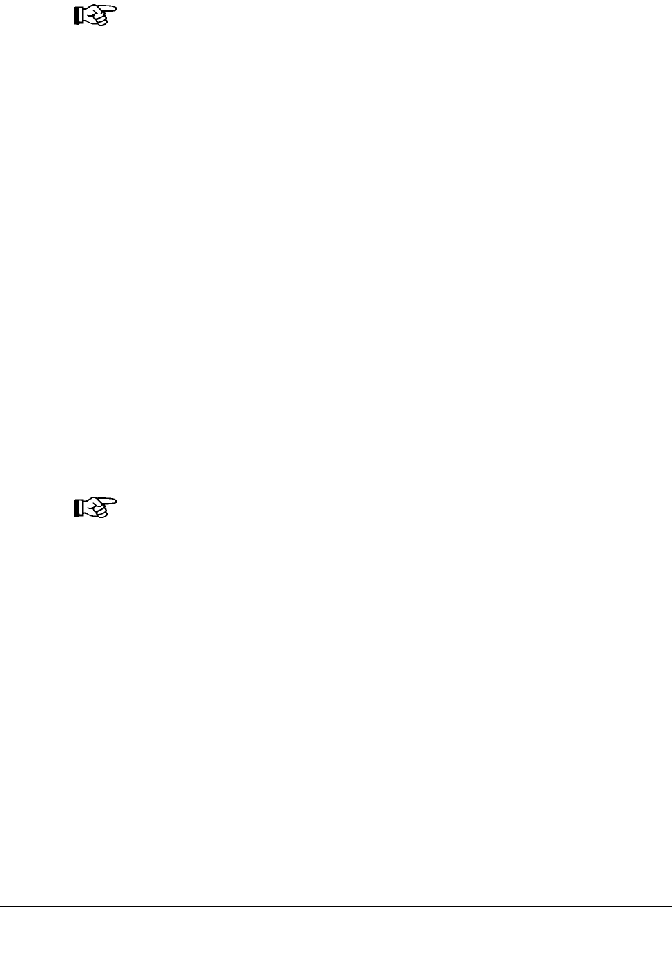
Chapter 4. Utility Functions 335
1st ed., 6/30/04 - 312579601
Note: The ‘‘|’’ symbol indicates that the user must choose either PRINTER or DISK.
where:
C
SYSOUT class for the printed report.
PRINTER
report is sent to the virtual printer of the userid executing the utility.
DISK
report is sent to disk.
fn, ft, fm
file name, file type, and file mode used if the report is sent to disk.
SLSIN
For SCP:
/FILE SLSIN *
For CMS:
SLSIN keywords
where:
keywords
Volume Report utility keywords.
Note: Input under CMS is restricted to one line only and does not contain the VOLRpt
utility indicator. Under SCP, input can span multiple lines, and the first line of any group is
preceded by the VOLRpt utility indicator.
SLSCDATA (CMS only)
SLSCDATA fn ft fm
where:
fn, ft, fm
file name, file type, and file mode which is to receive the data.
SLSSCRPL (CMS only)
SLSSCRPL fn ft fm
where:
fn, ft, fm
file name, file type, and file mode containing the SCRPOol statements.
Volume Report

336 VM/HSC 6.0 System Programmer’s Guide
1st ed., 6/30/04 - 312579601
SLSVA (CMS only)
SLSVA fn ft fm
where:
fn, ft, fm
file name, file type, and file mode containing the VOLATTR statements.
PARM
Parameters to pass to the SLUADMIN program.
For SCP:
/PARM parameters
For CMS:
PARM parameters
where:
parameters
any parameters acceptable to the SLUADMIN program.
JOB (SCP only)
Specifies the start of the Volume Report utility to SCP.
/JOB jobname programname
where:
jobname
identifier for the job.
programname
name of the program to be executed.
Volume Report

Chapter 4. Utility Functions 337
1st ed., 6/30/04 - 312579601
Invoking the Volume Report Utility
Depending upon the environment in which it is being run, the Volume Report utility can
be invoked in one of two ways:
• SLUVOLR EXEC (CMS)
• ACSUTIL SLKJCL file (SCP).
SLUVOLR EXEC (CMS)
The user can invoke the utility under CMS by running the SLUVOLR EXEC.
SLUVOLR fn ft fm
where:
fn, ft, fm
the parameter file description. If omitted, fn defaults to ‘‘SLUVOLR,’’ ft defaults to
‘‘PARMS,’’ and fm defaults to ‘‘*.’’ No placeholders are allowed for unspecified
parameters.
Parameter File
A parameter file for the Volume Report running under CMS contains statements similar to
those used to execute the utility under SCP. An example of a parameter file follows.
PARM MIXED
* SLSCDATA SLSCDATA DATA A
SLSSCRPL SCRPOOL STMTS A
SLSCNTL 160 DSN SLS200.SLSD.DBASEPRM
SLSPRINT PRINTER
SLSIN VOL(C84107)
Under SCP, the user can invoke the utility by entering the following command:
EXEC ACS UTIL VOLRpt
Execution of the statement results in the ACSUTIL SLKJCL file:
ACSUTIL SLKJCL File
/JOB jobname SLUADMIN
/PARM MIXED
/FILE SLSCNTL DEV vaddr DSN control.set.name
/FILE SLSPRINT DEV PRNT CLASS A
/FILE SLSVA DEV vaddr DSN <control.set.name> VOL <volume.name>
/FILE SLSIN *
* VOLRPT ACS(ascid) LSM(lsmlist)
* VOLRPT VOLSER(vol!list)
Volume Report

338 VM/HSC 6.0 System Programmer’s Guide
1st ed., 6/30/04 - 312579601
To execute the utility:
1. Delete the lines in the template that are not required, or leave the comment indicator
(*) in column one.
2. Remove the comment indicator from the desired lines.
3. Specify values for the desired parameters.
4. Delete the parameters that are not desired.
5. Enter the command ‘‘FILE.’’
The job file is then submitted to the ACS service machine for execution.
JCL Example
The following example shows JCL to produce a Volume Report for several LSMs.
JCL to Produce a Volume Report
The optional parameter ‘‘NOHDR’’ suppresses page headings on the volume report.
JCL to Produce a Volume Report for an VM or MVS PDS
The following example shows JCL to produce a Volume Report for ACS 00.
/JOB jobname SLUADMIN
/PARM NOHDR,MIXED
/FILE SLSCNTL DEV 505 DSN SLS.DBASEPARM
/FILE SLSPRINT DEV PRNT CLASS A
/FILE SLSIN *
* VOLRPT ACS(01) LSM(0,1,5)
/JOB SLSXUTIL SLUADMIN
/PARM MIXED
/FILE SLSCNTL DEV 501 DSN CDS.PRIM
/FILE SLSPRINT DEV PRNT CLASS A
/FILE SLSVA DEV 520 DSN VOLDEF.VOLATTR VOL HSC20B
/FILE SLSIN *
* VOLRPT ACS(00)
Volume Report

Chapter 4. Utility Functions 339
1st ed., 6/30/04 - 312579601
JCL to Produce a Volume Report for an MVS PDS
The following example shows JCL to produce a Volume Report for ACS 01.
Output Description
A report in the specified sort order provides details about the library volumes in the
ACSs/LSMs for which the report is produced. Other outputs may include error messages
to the listing.
Report Detail Lines
The following sections describe the detailed volume information reported for each
volume.
Media and Recording Technique Origin
The media and recording technique are derived from the media type reported by the LMU
(recorded in the VAR) and the applicable VOLATTR statement, if one exists. If the media
type from the LMU is compatible with the VOLATTR statement, the VOLATTR’s media
type and recording technique is reported. If the LMU and VOLATTR data and
VOLATTR data is incompatible, or the VOLATTR is not provided, the LMU media type
is used.
/JOB SLSXUTIL SLUADMIN
/PARM MIXED
/FILE SLSCNTL DEV 501 DSN CDS.PRIM
/FILE SLSPRINT DEV PRNT CLASS A
/FILE SLSVA DEV 520 DSN SOS600.SPSB.PARMLIB(VOLATTR) VOL HSC20B
/FILE SLSIN *
* VOLRPT ACS(01)
Volume Report

340 VM/HSC 6.0 System Programmer’s Guide
1st ed., 6/30/04 - 312579601
Media Type Prefix Characters
If discrepancies exist between the media type reported by the LMU (in the VAR) and the
VOLATTR information, the media type is prefixed by one of the following characters:
*
displayed if the VAR media type and VOLATTR information do not match. In this
case, the user should correct the erroneous VOLATTRs.
-
displayed if both of these conditions are true:
• a VOLATTR cannot be found for an ECART, ZCART, helical, or STK1
cartridge (anything other than a Standard cartridge), and
• the cartridge external media label has been verified by the LMU.
@
displayed if both of these conditions are true:
• a VOLATTR exists for an ECART, ZCART, helical, or STK1 cartridge
(anything other than a Standard cartridge), and
• the cartridge external media label has not been verified by the LMU.
Errant, Scratch, Selected Fields
A flag of ‘‘Y’’ (yes) under the Errant (Err), Scratch (Scr), or Selected (Sel) headings
indicates that the volume is currently in that status.
A volume in Errant (Err) status shows the volume’s home cell in the Cell Loc column.
Under the Selected heading, a flag of “Y” indicates that the volume is currently selected,
that is, being mounted, dismounted, ejected, or moved. A flag of “M” indicates that the
volume is currently mounted. The Selected column on the totals report includes both
selected and mounted volumes. The volume’s home cell appears in the Cell Loc column.
External Label Field
Under the heading External Label (Ext Lbl), ‘‘R’’ indicates that the volume has a readable
external label. A flag of ‘‘U’’ (unreadable) means that the cartridge has an external label
which the camera system is unable to read. ‘‘N’’ indicates that the cartridge has no
external label.
Cartridge Usability (CLN USE) Field
An ‘‘N’’ indicates a cartridge which is not usable, for example, a spent cleaning cartridge
that is not usable because it has exhausted its cleaning surface. An ‘‘M’’ means that a
cleaning cartridge has exceeded its maximum usage set by the VOLATTR MAXclean or
MNTD MAXclean value.
Volume Report
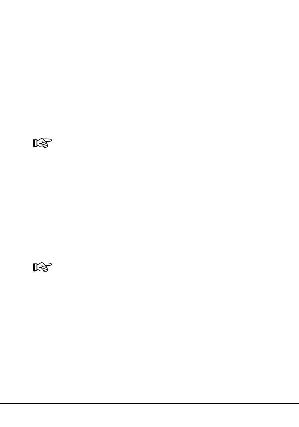
Chapter 4. Utility Functions 341
1st ed., 6/30/04 - 312579601
Subpool ID Field
Scratch subpools for volumes are listed if:
•SUMMary(SUBpool) is specified and
• scratch subpool definitions have been provided by SCRPOol control statements.
If the VOLSER is not within any scratch subpool range,
** DEFAULT **
appears in this field.
Times Selected Field
The Times Selected count is the number of times the volume has been selected for use by
a host. A single selection may represent a mount/dismount pair, the volume’s initial entry,
participation in scratch redistribution, or any update to its scratch status.
Note: The count is valid only for the time that the volume exists in a CDS.
Totals Reports
Two totals reports can be produced:
• Volume Report Totals
• Subpool Totals.
Volume Report Totals
Total of cartridges with various characteristics are displayed for LSMs, ACSs, and the
entire library.
The total selected volumes is the sum of the number of volumes currently selected and the
number of volumes currently mounted.
Note: The free storage cells reported do not include free cells on frozen panels. An LSM
with at least one frozen panel is indicated by an asterisk after the free cell count.
Subpool Totals
Totals of cartridges by subpool are produced for LSMs, ACSs, and the entire library.
Volume Report

342 VM/HSC 6.0 System Programmer’s Guide
1st ed., 6/30/04 - 312579601
Volume Report Flat Files
Specifying the VOLDATA parameter produces a volume flat file. The layout of the
volume records is defined by the SMP/E-distributed SLUVVDAT macro. Refer to
Appendix C, “Record Formats” on page 497 to see the SLUVVDAT record format.
When VOLDATA is specified under CMS, only the volume information that passed all of
the selection criteria is written to the specified output data set, one volume per record.
The CDSDATA parameter creates a non-volume CDS flat file. The following
SMP/E-distributed macros define the non-volume information:
• SLUVADAT (flat file ACS/LSM information DSECT)
• SLUVCDAT (flat file static configuration data DSECT)
• SLUVHDAT (flat file host information DSECT)
• SLUVIDAT (flat file CDS information DSECT).
Refer to Appendix C, “Record Formats” on page 497 for the layouts of these records.
An optional parameter, ‘‘NOHDR,’’ may be specified in the JCL to eliminate printing
page headings. This option enables the user to customize the output data to produce
reports in various formats.
Volume Report

Chapter 4. Utility Functions 343
1st ed., 6/30/04 - 312579601
SLUADMIN (n.n.n) StorageTek Automated Cartridge System Utility PAGE 0001
TIME hh:mm:ss Control Card Image Listing DATE yyyy-mm-dd
VOLRPT SUMMARY(TOTAL) VOLUME(CLN400-CLN418)
SLUADMIN (n.n.n) StorageTek Automated Cartridge System Utility PAGE 0002
TIME hh:mm:ss Volume Report Utility DATE yyyy-mm-dd
Volume Cell Loc Ext Cln |--- Inserted --| |-- Last Used-- | Times
Serial Media Rectech LSM:Pa:Ro:Co Err Scr Sel Lbl Use Subpool ID Date Time Date Time Selected
CLN400 STK1U STK1R 01:01:14:00:17 R N **Default** 20040216 12:56:56 20040216 13:11:10 23
CLN401 STANDARD 18TRACK 01:01:18:00:19 R **Default** 20040216 12:56:57 20040216 13:11:17 98
CLN402 STANDARD 18TRACK 01:01:01:00:23 R M **Default** 20040216 12:56:59 20040216 13:11:20 101
CLN403 STANDARD 18TRACK 01:01:04:00:23 R **Default** 20040216 12:57:00 20040216 13:11:25 96
CLN404 STK1U STK1R 01:01:06:00:20 R NM **Default** 20040216 12:57:01 20040216 13:11:27 105
CLN405 STK1U STK1R 01:01:07:01:10 R N **Default** 20040216 12:57:03 20040216 13:11:30 26
CLN406 *STANDARD 18TRACK 01:00:03:30:01 R **Default** 20040216 12:57:04 20040216 13:05:51 3
CLN407 *STANDARD 18TRACK 01:00:00:15:02 R **Default** 20040216 12:57:05 20040216 13:05:53 3
CLN408 STANDARD 18TRACK 01:00:02:15:05 R **Default** 20040216 12:57:06 20040216 13:05:54 3
CLN409 STANDARD 18TRACK 01:00:03:30:02 R **Default** 20040216 12:57:06 20040216 13:05:56 3
CLN410 @DD3D DD3 01:00:00:15:03 R M **Default** 20040216 12:57:08 20040216 13:05:58 3
CLN411 @DD3D DD3 01:00:02:16:00 R M **Default** 20040216 12:57:08 20040216 13:06:00 3
CLN412 DD3D DD3 01:00:03:31:00 R M **Default** 20040216 12:57:11 20040216 13:06:02 3
CLN413 -DD3D DD3 01:00:00:15:04 R M **Default** 20040216 12:57:12 20040216 13:06:04 3
CLN414 DD3D DD3 01:00:02:16:01 R M **Default** 20040216 12:57:13 20040216 13:06:05 3
CLN415 DD3D DD3 01:00:03:31:01 R M **Default** 20040216 12:57:14 20040216 13:06:07 3
CLN416 DD3D DD3 01:00:00:15:05 R M **Default** 20040216 12:57:17 20040216 13:06:11 3
CLN417 DD3D DD3 01:00:02:16:02 R M **Default** 20040216 12:57:18 20040216 13:06:14 3
CLN418 DD3D DD3 01:00:03:31:02 R M **Default** 20040216 12:57:20 20040216 13:06:16 3
SLUADMIN (n.n.n) StorageTek Automated Cartridge System Utility PAGE 0003
TIME hh:mm:ss Volume Report Totals DATE yyyy-mm-dd
No Un External Non Not Over Free
Type Loc Errant Selected External Readable Readable Scratch Scratch Usuable MAXclean All Cells
LSM 00:00 0 0 0 0 0 0 0 0 0 0 4069
____ _____ ______ ________ ________ ________ ________ _______ _______ _______ ________ ___ ____
ACS 00 0 0 0 0 0 0 0 0 0 0 4069
LSM 01:00 0 0 0 0 13 0 13 0 9 13 346
LSM 01:01 0 0 0 0 6 0 6 3 2 6 4660
____ ___ ______ ________ ________ ________ ________ _______ _______ _______ ________ ___ ____
ACS 01 0 0 0 0 19 0 19 3 11 19 5006
ALL 0 0 0 0 19 0 19 3 11 19 9075
Figure 21. Volume Report SUMMary(TOTal) Sample Output
Volume Report

344 VM/HSC 6.0 System Programmer’s Guide
1st ed., 6/30/04 - 312579601
SLUADMIN (n.n.n) StorageTek Automated Cartridge System Utility PAGE 0001
TIME hh:mm:ss Control Card Image Listing DATE yyyy-mm-dd
VOLRPT SUMMARY(SUB) VOLUME(EE0000-EE9999)
SLUADMIN (n.n.n) StorageTek Automated Cartridge System Utility PAGE 0002
TIME hh:mm:ss Volume Report Utility DATE yyyy-mm-dd
Volume Cell Loc Ext Cln |--- Inserted --| |-- Last Used-- | Times
Serial Media Rectech LSM:Pa:Ro:Co Err Scr Sel Lbl Use Subpool ID Date Time Date Time Selected
EE0000 ZCART 36CTRACK 01:00:02:00:01 R SUB1 20040214 15:14:39 20040221 10:16:59 5453
EE0001 ZCART 36CTRACK 01:00:03:01:00 Y R SUB1 20040210 11:30:51 20040221 16:23:56 28
EE0002 ZCART 36CTRACK 01:00:00:00:00 Y R SUB1 20040210 11:30:55 20040221 16:23:56 29
EE0003 ZCART 36CTRACK 01:00:01:36:01 Y Y Y R SUB1 20040210 11:31:01 20040221 16:23:57 25
EE0004 ZCART 36CTRACK 01:00:02:01:02 Y R SUB1 20040210 11:31:07 20040221 16:23:57 27
EE0005 ZCART 36CTRACK 01:00:03:01:01 Y R SUB1 20040210 11:31:12 20040221 16:23:57 23
EE0006 ZCART 36CTRACK 02:00:00:00:00 Y R SUB1 20040214 14:48:10 20040218 10:33:07 6
EE0007 ZCART 36CTRACK 02:01:00:04:03 Y R SUB1 20040214 09:39:53 20040218 10:33:08 100
EE0008 ZCART 36CTRACK 02:00:01:39:01 Y R SUB1 20040214 09:40:07 20040218 10:33:08 45
EE0009 ZCART 36CTRACK 02:00:00:02:00 M R SUB1 20040214 09:40:19 20040221 16:34:17 676
EE0010 ZCART 36CTRACK 02:01:01:39:02 Y R SUB1 20040214 09:40:33 20040221 16:23:58 82
EE0011 ZCART 36CTRACK 02:01:00:08:01 Y R SUB1 20040214 14:24:46 20040221 16:24:00 15
EE0012 ZCART 36CTRACK 02:00:01:36:01 Y R SUB1 20040214 08:33:30 20040218 10:33:08 19
EE0800 ZCART 36CTRACK 01:01:01:00:04 R SUB2 20040210 10:58:04 20040221 16:26:39 64
EE0801 ZCART 36CTRACK 01:01:14:00:04 Y R SUB2 20040210 10:57:13 20040218 12:44:54 34
EE0802 ZCART 36CTRACK 01:01:03:31:01 Y R SUB2 20040210 10:57:20 20040218 10:33:09 30
EE0803 ZCART 36CTRACK 01:01:16:00:06 Y R SUB2 20040210 10:57:27 20040218 13:12:31 34
EE0804 ZCART 36CTRACK 01:01:17:00:10 Y R SUB2 20040210 10:57:35 20040218 10:33:09 30
EE0805 ZCART 36CTRACK 01:01:18:00:06 Y R SUB2 20040210 10:57:43 20040218 10:33:09 7
EE0806 ZCART 36CTRACK 01:01:19:00:05 Y R SUB2 20040210 10:57:49 20040218 12:54:17 34
EE0807 ZCART 36CTRACK 01:01:00:00:01 Y R SUB2 20040210 10:57:58 20040218 13:08:24 34
EE0808 ZCART 36CTRACK 01:01:13:00:02 Y R SUB2 20040210 10:53:06 20040218 13:04:13 34
EE0809 ZCART 36CTRACK 02:01:01:36:00 Y R SUB2 20040220 10:33:04 20040218 10:33:10 50
Figure 22. Volume Report Utility SUMMary(SUBpool) Sample Output
(1 of 2)
Volume Report

Chapter 4. Utility Functions 345
1st ed., 6/30/04 - 312579601
SLUADMIN (n.n.n) StorageTek Automated Cartridge System Utility PAGE 0003
TIME hh:mm:ss Subpool Totals, All Ranges ATE yyyy-mm-dd
SUBPOOL ID LABEL TYPE RANGE LIMITS
SUB1 SL N/A - N/A
NON
ACS LSM SCRATCH SCRATCH Media Rectech
00 00:00 0 0
_______ _______
ACS Total 0 0
01 00:10 5 1 ZCART 36CTRACK
00:10 0 0
_______ _______
ACS Total 5 1
02 00:20 3 1 ZCART 36CTRACK
00:21 3 0 ZCART 36CTRACK
_______ ________
ACS Total 6 1
Library Total 11 2
Figure 22. Volume Report Utility SUMMary(SUBpool) Sample Output
(2 of 2)
Volume Report

346 VM/HSC 6.0 System Programmer’s Guide
1st ed., 6/30/04 - 312579601

Chapter 5. Problem Determination, Diagnostics, and Recovery 347
1st ed., 6/30/04 - 312579601
Chapter 5. Problem Determination, Diagnostics, and
Recovery
Overview
The following indicators and facilities may be used in the determination of the source of a
perceived problem.
• Messages
• ABEND codes
• Software trace facilities
• Diagnostic capabilities
• Recovery capabilities
• Dump processing
• Major SCP data relationships.
Messages
HSC Messages
Messages with the prefixes: ‘‘SLSxxxxs’’ are emitted by the HSC, and are documented in
the HSC Messages and Codes Guide.
SCP Messages
Messages with the prefixes: ‘‘SLKxxxnnns’’ are emitted by the SCP, and are documented
in the SCP Messages and Codes Guide.
Abend Codes
HSC ABEND Codes
ABEND codes of the form ‘‘U1096-xxxx’’ are emitted by the HSC, and are documented
in the HSC Messages and Codes Guide.
SCP ABEND Codes
All other ABEND codes are emitted by the SCP, and are documented in the SCP Messages
and Codes Guide.

348 VM/HSC 6.0 System Programmer’s Guide
1st ed., 6/30/04 - 312579601
Software Trace Facilities
There is a hierarchy of facilities that may be used to trace the activity of the ACS service
machine. They range from standard VM services, to SCP and HSC services. Utilities are
also provided.
The SCP and the HSC have separate trace facilities. Both have internal and external trace
functions. The use of the HSC ‘‘TRACE’’ command (external trace) involves an
interaction with the SCP ‘‘TRACE’’ command. The trace facility hierarchy involves the
following:
• CP trace table
• CCWTRACE
• VM (CP) debug commands
• SCP SET TRACE command (also, SCP TRACE)
• SCP internal trace table
• IPARML (IUCV parameter list)
• IUCV interrupt buffer
• SCP external trace facility
• SCP Trace Formatter utility
• Supervisor Call (SVC) functions
• SCP GTRACE emulation
• HSC internal trace table
• HSC TRace command.
CP Trace Table
The CP component of VM has its own internal trace table. For the VM/SP, VM/SP HPO,
and VM/ESA 370 feature, use the CP ‘‘CPTRAP’’ function to enable and disable event
tracing, and the ‘‘TRAPRED’’ function to format entries. For VM/XA and VM/ESA, use
‘‘SET CPTRACE,’’ ‘‘TRSOURCE,’’ and ‘‘TRSAVE’’ to gather trace data and
‘‘TRACERED’’ to format it. These functions require special virtual machine
authorization. See the appropriate VM documentation for details.
CCWTRACE
CCWTRACE is a CP command used for I/O tracing in VM/SP, VM/SP HPO and
VM/ESA 370.
There are several options that control the operation of CCWTRACE. It is recommended
that you contact StorageTek Software Support to insure that the proper CCWTRACE
options are specified to capture the necessary data for the particular problem at hand.
Note: For VM/XA and VM/ESA, this function is replaced by ‘‘SET CPTRACE,’’
‘‘TRSOURCE,’’ ‘‘TRSAVE,’’ and ‘‘TRACERED.’’

Chapter 5. Problem Determination, Diagnostics, and Recovery 349
1st ed., 6/30/04 - 312579601
VM (CP) Debug Commands
The following CP commands are useful in diagnosing problems in the system. See
appropriate VM documentation for details on syntax and use.
SCP SET TRACE Command
The SET TRACE command allows the operator to enable and disable the control program
execution trace feature. It is also known as the TRACE command. In essence, SET
TRACE corresponds to the Generalized Trace Facility (GTF) in MVS. Refer to “SCP
External Trace Facility” on page 367 for more information about SCP tracing.
This command interacts with the HSC TRace command. The SCP TRACE command
must have event USR enabled, and the HSC TRace command must have some component
enabled for tracing for there to be any HSC event tracing.
TRACE Command Syntax
For a detailed description of how to use the TRACE command, refer to the HSC
Operator’s Guide.
SCP Internal Trace Table
The SCP internal trace table is comprised of two data areas:
• MTTH (Master Trace Table Header), and
• trace table entries.
Events for the system TRACE task (SLKTKT) are not traced internally or externally. The
internal trace table does NOT contain ‘USR’ events generated by the GTRACE function.
ADSTOP Single address stop (VM/SP, VM/SP HPO, and VM/ESA 370)
BEGIN Start execution
CPTRACE Enable and disable event tracing (VM/XA and VM/ESA)
CPTRAP Enable and disable event tracing (VM/SP, VM/SP HPO, VM/ESA 370)
DISPLAY Display registers, PSW, storage
STORE Alter registers, PSW, storage
TRACE/PER Multiple break-points
TRAPRED Format CP trace table (VM/SP, VM/SP HPO, and VM/ESA 370)
TRSAVE Define locations for saving trace data
TRSOURCE Define I/O, data, and guest traces (VM/XA and VM/ESA)
VMDUMP Dump the virtual machine’s storage.

350 VM/HSC 6.0 System Programmer’s Guide
1st ed., 6/30/04 - 312579601
Master Trace Table Header
A data area, called the Master Trace Table Header (MTTH) is a 32-byte header which
describes the actual trace table. The address of the MTTH is in the 4-byte area at absolute
address x’54’ (label TRCTAB in structure NUCON). The MTTH actually resides in the
CVT at offset x’238’ (label CVTMTTH).
The format of the MTTH is:
*-------------------------------------------*
x’00’ | MTTCURR | MTTFIRST | MTTLAST | reserved |
*-------------------------------------------*
x’10’ | MTTWRAP | MTTQCNT | MTTQLIM | ‘MTT’ |
*-------------------------------------------*
Trace Table Entries
Each trace table entry (TTE) is 32 bytes long. The default trace table size is 8k bytes (256
entries). All SCP events are recorded, regardless of the state of the external trace (SCP
‘TRACE command). ‘‘USR’’ events (GTRACE) events are never recorded in the SCP
internal trace table. Instead, USR events generated by the HSC are recorded in the HSC
internal trace table.
The TTE contains common information about every event, and some data specific to each
event type.
* STANDARD TRACE TABLE ENTRY (TTE)
Offset *------------------------------------------------*
x’00’ | PSW at the time of the event |
*------------------------------------------------*
x’08’ | event | | event | TTEWORD1 ( 4 bytes of |
| type | flag | code | event-dependent data) |
*------------------------------------------------*
x’10’ | TTEWORD2 ( 4 bytes of | TTEWORD3 ( 4 bytes of |
| event-dependent data)| event-dependent data) |
*------------------------------------------------*
x’18’ | TBLOK address | TOD (bytes 3-6) |
| of current task | at time of event |
*------------------------------------------------*
MTTCURR the address of the current TTE (actually the last entry made)
MTTFIRST the address of first TTE MTTLAST the address of (byte after) last entry
MTTLAST the address of (byte after) last entry
MTTWRAP is the TOD (bytes 3-6) of last wrap (or first entry)
MTTQCNT is the number of events queued since POSTING (since TRACE task was
POSTed)
MTTQLIM is the number of events to queue before POSTING
MTTEYE is the eye catcher: c’MTT ‘

Chapter 5. Problem Determination, Diagnostics, and Recovery 351
1st ed., 6/30/04 - 312579601
DSP Trace Entry
event-type = ‘D’
event-code
TTEWORD1
TTEWORD2
TTEWORD3
= dispatch priority
= R15
= R12
= R13
Return from SVC Trace Entry
event-type
event-code
TTEWORD1
TTEWORD2
TTEWORD3
= ‘W’
= dispatch priority
= R15
= R0
= R1
SIO Trace Entry
event-type
event-code
TTEWORD1
TTEWORD2
TTEWORD3
= ‘S’
= device address
= IOB address
= CAW
= Reserved
I/O Trace Entry
event-type
event-code
TTEWORD1
TTEWORD2
TTEWORD3
= ‘I’
= device address
= IOB address
= CSW (bytes 0-3)
= CSW (bytes 4-7)
SVC Trace Entry
event-type
event-code
TTEWORD1
TTEWORD2
TTEWORD3
= ‘V’
= SVC number
= R15
= R0
= R1
PGM Trace Entry
event-type
event-code
TTEWORD1
TTEWORD2
TTEWORD3
= ‘P’
= program interrupt code
= R15
= R12
= R1
MCK Trace Entry
event-type
event-code
TTEWORD1
TTEWORD2
TTEWORD3
= ‘M’
= machine check interrupt code (bytes 0-3)
= machine check interrupt code (bytes 4-7)
= external damage code
= failing storage address

352 VM/HSC 6.0 System Programmer’s Guide
1st ed., 6/30/04 - 312579601
RST Trace Entry
event-type
event-code
TTEWORD1
TTEWORD2
TTEWORD3
= ‘R’
= (unused)
= (unused)
= (unused)
= (unused)
EXT Trace Entry
event-type
event-code
x’0040’
x’1004’
x’1005’
x’2402’
x’4000’
= ‘E’
= external interrupt code:
= ‘CP EXT’ (generic external interrupt)
= CLKC (TOD clock comparator)
= CPUT (CPU Timer)
= LDEV interrupt (logical device)
= IUCV interrupt
external interrupt (subtype EXT):
TTEWORD1:
TTEWORD2
TTEWORD3
unused
unused
unused
external interrupt (subtype CLKC):
TTEWORD1:
TTEWORD2:
TTEWORD3:
unused
clock comparator value (bytes 0-3)
clock comparator value (bytes 4-7)
external interrupt (subtype CPUT):
TTEWORD1:
TTEWORD2:
TTEWORD3:
0 or JBLNTIM count if task was deferred
Task name if deferred
Task name if deferred
external interrupt (subtype IUCV):
TTEWORD1:
TTEWORD2:
TTEWORD3:
IRT address
interrupt buffer IPARML (bytes 0-3) (includes IPTYPE-interrupt
subtype)
interrupt buffer IPARML (bytes 4-7)
IUC Trace Entry
event-type = ‘C’
event-code = IUCV function performed (only items marked with ‘‘*’’ in Table
5-1 are performed):
Table 19. IUCV Functions
Code Query
X’00’ QUERY
X’01’ TESTMSG
X’02’ * RTRVBFR

Chapter 5. Problem Determination, Diagnostics, and Recovery 353
1st ed., 6/30/04 - 312579601
TTEWORD1 = IRT address
TTEWORD2 = IPARML (bytes 0-3)
TTEWORD3 = IPARML (bytes 4-7)
IPARML (IUCV Parameter List)
The IPARML (IUCV Parameter List) is a VM data structure that contains IUCV
information passed to and from the user of IUCV services.
At the time a virtual machine executes the IUCV instruction, a register points to an
IPARML containing information about the request. The IUCV instruction modifies the
caller’s IPARML in storage.
The IPARML is also used to map the ‘‘IUCV external interrupt buffer’’ that is filled in at
the time an IUCV external interrupt occurs. It contains information describing the event
that just occurred.
The first 8 bytes of the IPARML are saved in the TTE when tracing IUCV events.
IPRCODE is the return code from the IUCV instruction. A list of IPRCODE meanings
follows these IPARML samples.
Refer to VM IUCV documentation for details on this and other fields.
X’03’ DESCRIBE
X’04’ * SEND
X’05’ * RECEIVE
X’06’ * REPLY
X’07’ TEST COMPLETION
X’08’ * REJECT
X’09’ PURGE
X’0A’ * ACCEPT
X’0B’ * CONNECT
X’0C’ * DECLARE BUFFER
X’0D’ * QUIESCE
X’0E’ RESUME
X’0F’ * SEVER
X’10’ SET MASK
X’11’ SETCMASK
Table 19. IUCV Functions
Code Query

354 VM/HSC 6.0 System Programmer’s Guide
1st ed., 6/30/04 - 312579601
The IPARML fields are defined by VM. Examples of some common operations are:
IUCV CONNECT to *BLOCKIO
IUCV SEND to *BLOCKIO
IUCV RECEIVE
IUCV REPLY
IUCV SEVER
IPARML for IUCV CONNECT to *BLOCKIO
*----------------------------------------------------------*
x’00’ | Path ID |flags 1|IPRCODE| IPMSGLIM | xx | xx |
*------+------+-------+-------+--------+-----+------+------+
x’08’ | IPVMID= ‘*BLOCKIO’ |
*------+------+-------+-------+--------+-----+------+------+
x’10’ | Block size | Block Offset |
*------+------+-------+-------+-------+------+------+------+
x’18’ | Vdevaddr | xx | xx | xx | xx | xx | xx |
*------+------+-------+-------+--------+-----+------+------+
x’20’ | Buffer Length | xx | xx | xx | xx |
*----------------------------------------------------------+
Inputs:
IPVMID = userid to connect to
= ‘*BLOCKIO’
Block size
Block offset
= data set block size
= number of blocks from beginning of device to data set
beginning
Vdevaddr = virtual device address
Outputs:
IPPATHID
IPRCODE
IPMSGLIM
flags1
= IUCV pathid
= IUCV return code
= max. # of concurrent messages on the path
= IPFLAGS1
= path status & privilege flags

Chapter 5. Problem Determination, Diagnostics, and Recovery 355
1st ed., 6/30/04 - 312579601
IPARML for IUCV SEND to *BLOCKIO
*----------------------------------------------------------*
x’00’ | Path ID |flags 1|IPRCODE| IPMSGID = message id |
*------+------+-------+-------+--------+-----+------+------+
x’08’ | IPTRGCLS = target class | IPRMMSG1 = block number |
| (1-write) (2=read) | |
*------+------+-------+-------+------+------+------+-------+
x’10’ | IPRMMSG2 = bufffer address | xx | xx | xx | xx |
*------+------+-------+-------+------+------+------+-------+
x’18’ | xx | xx | xx | xx | xx | xx | xx | xx |
*------+------+-------+-------+------+------+------+-------+
x’20’ | xx | xx | xx | xx | xx | xx | xx | xx |
*----------------------------------------------------------+
Inputs:
IPPATHID
IPTRGCLS
IPFLAGS1
Block number
Buffer addr
= IUCV path id
= target class (1=write; 2=read)
= flags (type=2way)
= relative block number
= data buffer address
Outputs:
IPMSGID
IPRCODE
= IUCV message id
= IUCV return code

356 VM/HSC 6.0 System Programmer’s Guide
1st ed., 6/30/04 - 312579601
IPARML for IUCV RECEIVE
*----------------------------------------------------------*
x’00’ | Path ID |flags 1|IPRCODE| IPMSGID = message id |
*------+------+-------+-------+--------+-----+------+------+
x’08’ | IPTRGCLS = target class | IPBFADR1 = buffer address |
*------+------+-------+-------+------+------+------+-------+
x’10’ | IPBFLN1F = bufffer length | xx | xx | xx | xx |
*------+------+-------+-------+------+------+------+-------+
x’18’ | xx | xx | xx | xx | xx | xx | xx | xx |
*------+------+-------+-------+------+------+------+-------+
x’20’ | IPBFLN2F = reply length | xx | xx | xx | xx |
*----------------------------------------------------------+
Inputs:
IPPATHID
IPTRGCLS
IPFLAGS1
IPBFRADR1
IPBFLN1F
= IUCV path id
= target class
= flags
= data buffer address
= data buffer length
Outputs:
IPMSGID
IPRCODE
IPBFLN2F
IPFLAGS1
IPBFADR1
IPBFLN1F
= IUCV message id
= IUCV return code
= length of allowable reply (if any)
= flag bits
= address of last byte RECEIVEd + 1
= length of remaining message text

Chapter 5. Problem Determination, Diagnostics, and Recovery 357
1st ed., 6/30/04 - 312579601
IPARML for IUCV REPLY
*----------------------------------------------------------*
x’00’ | Path ID |flags 1|IPRCODE| IPMSGID= message id |
*------+------+-------+-------+--------+-----+------+------+
x’08’ | IPTRGCLS = target class | xx | xx | xx | xx |
*------+------+-------+-------+------+------+------+-------+
x’10’ | xx | xx | xx | xx | xx | xx | xx | xx |
*------+------+-------+-------+------+------+------+-------+
x’18’ | xx | xx | xx | xx |IPBFADR2= reply buffer addr |
*------+------+-------+-------+------+------+------+-------+
x’20’ | IPBFLN2F = reply length | xx | xx | xx | xx |
*----------------------------------------------------------+
Inputs:
IPPATHID
IPMSGID
IPTRGCLS
IPFLAGS1
IPBFRADR2
IPBFLN2F
= IUCV path id
= IUCV message id
= target class
= flags
= reply buffer address
=reply buffer length
Outputs:
IPRCODE
IPBFLN2F
IPFLAGS1
IPBFADR2
= IUCV return code
= length of residual reply text
= flag bits
= address of last byte REPLYd + 1

358 VM/HSC 6.0 System Programmer’s Guide
1st ed., 6/30/04 - 312579601
IPARML for IUCV SEVER
*----------------------------------------------------------*
x’00’ | Path ID | xx |IPRCODE| xx | xx | xx | xx |
*------+------+-------+-------+--------+-----+-----+--- ---+
x’08’ | IPVMID= userid connected to |
*------+------+-------+-------+------+------+------+-------+
x’10’ | xx | xx | xx | xx | xx | xx | xx | xx |
*------+------+-------+-------+------+------+------+-------+
x’18’ | xx | xx | xx | xx | xx | xx | xx | xx |
*------+------+-------+-------+------+------+------+-------+
x’20’ | xx | xx | xx | xx | xx | xx | xx | xx |
*----------------------------------------------------------+
Inputs:
Outputs:
IPPATHID
IPVMID
= IUCV path id
= name of virtual machine connected to
IPRCODE = IUCV return code

Chapter 5. Problem Determination, Diagnostics, and Recovery 359
1st ed., 6/30/04 - 312579601
IPRCODE
The following is a list of IPRCODE values and meanings from DMKSP MACLIB
member IUCVBLOK for VM/SP, VM/SP HPO and VM/ESA 370. For VM/XA and
VM/ESA, the codes are defined in CPLIB MACLIB member IPARML. The codes are
also documented in the IBM VM/SP System Programmer’s Guide and System Facilities for
Programming documents.
1 invalid path id
2 path quiesced - no sends allowed
3 message limit exceeded
4 priority messages not allowed on path
5 buffer too short for message
6 fetch protection exception
7 addressing exception
8 msgid found, but class/path invalid
9 message has been purged
10 message length negative
11 target is not logged on
12 target has not declared a buffer
13 invoker max connections exceeded
14 target max connections exceeded
15 not authorized to connect to target
16 invalid cp system service name
17 invalid function code
18 invalid msglimit
19 already has declared a buffer
20 path has been severed
21 parameter list message not allowed
22 send list invalid
23 negative length in list
24 invalid total list length
25 prmmsg and buflist/anslist not allowed
26 buffer list not d-word aligned
27 answer list not d-word aligned

360 VM/HSC 6.0 System Programmer’s Guide
1st ed., 6/30/04 - 312579601
IUCV Interrupt Buffer
As an IUCV-type external interrupt occurs, CP places data in the IUCV external interrupt
buffer. The data describes the type of IUCV event, and data specific to each event subtype.
For a full description, see the appropriate VM documentation.
The external interrupt is traced in the internal trace table, and the first 8 bytes of the
IPARML are saved in the TTE.
The following is a list of possible IUCV interrupt codes.
28 no control buffer exists
48 function not supported for CSS
IPTYPE Interrupt Type
X’01’ -- Pending Connection
X’02’ -- Connection Complete
X’03’ -- Path has been Severed
X’04’ -- Path has been Quiesced
X’05’ -- Path has been Resumed
X’06’ -- Pending Priority Message Completion
X’07’ -- Pending Non-priority Message Completion
X’08’ -- Pending Priority Message
X’09’ -- Pending Non-priority Message

Chapter 5. Problem Determination, Diagnostics, and Recovery 361
1st ed., 6/30/04 - 312579601
IPARML for Pending Connection Interrupt
*----------------------------------------------------------*
x’00’ | IPPATHID | Flag 1| 01 | IPMSGLIM | xx | xx |
*------+------+-------+-------+--------+-----+-----+--- ---+
x’08’ | IPVMID= userid wishing to establish the connection |
*------+------+-------+-------+------+------+------+-------+
x’10’ | IPUSER |
*------+------+-------+-------+------+------+------+-------+
x’18’ | IPUSER |
*------+------+-------+-------+------+------+------+-------+
x’20’ | xx | xx | xx | xx | xx | xx | xx | xx |
*----------------------------------------------------------+
where:
IPPATHID
Flag 1
IPMSGLIM
IPVMID
IPUSER
= IUCV pathid
= IPFLAGS1
= privilege flags
= max. number of concurrent messages allowed on path
= user ID wishing to establish the connection
= 16 bytes of application-dependent data
For the SCP, the first 8 bytes are the ‘ddname’ of the file to
communicate with:
‘SLSTLMS’ = tape management interface
‘CMDIUCV’ = operator commands

362 VM/HSC 6.0 System Programmer’s Guide
1st ed., 6/30/04 - 312579601
IPARML for Connection Complete Interrupt
*----------------------------------------------------------*
x’00’ | IPPATHID | Flag 1| 02 | IPMSGLIM | xx | xx |
*------+------+-------+-------+------+-------+-----+--- ---+
x’08’ | xx + xx + xx + xx + xx + xx + xx + xx |
*------+------+-------+-------+------+------+------+-------+
x’10’ | IPUSER |
*------+------+-------+-------+------+------+------+-------+
x’18’ | IPUSER |
*------+------+-------+-------+------+------+------+-------+
x’20’ | xx | xx | xx | xx | xx | xx | xx | xx |
*----------------------------------------------------------+
where:
IPPATHID
Flag 1
IPMSGLIM
IPUSER
= IUCV pathid
= IPFLAGS1
= privilege flags
= max. number of concurrent messages allowed on path
= 16 bytes of application-dependent data (perhaps) modified by the
user ID that ACCEPTed the path
For *BLOCKIO:
IPUSER+0: DS F start block number
IPUSER+0: DS F end block number
IPUSER+0: DS H flags

Chapter 5. Problem Determination, Diagnostics, and Recovery 363
1st ed., 6/30/04 - 312579601
IPARML for Path Severed/REsumed/Quiesced Interrupt
*----------------------------------------------------------*
x’00’ | IPPATHID | xx | IPTYPE| xx | xx | xx | xx |
*------+------+-------+-------+------+------+--- --+--- ---+
x’08’ | xx | xx | xx | xx | xx | xx | xx | xx |
*------+------+-------+-------+------+------+------+-------+
x’10’ | IPUSER |
*------+------+-------+-------+------+------+------+-------+
x’18’ | IPUSER |
*------+------+-------+-------+------+------+------+-------+
x’20’ | xx | xx | xx | xx | xx | xx | xx | xx |
*----------------------------------------------------------+
Inputs:
IPPATHID
IPTYPE
IPUSER
= IUCV path id
= 03=severed, 04=quiesced, 05=resumed
= 16 bytes of application-dependent data. The SCP itself, does not
use this data.

364 VM/HSC 6.0 System Programmer’s Guide
1st ed., 6/30/04 - 312579601
IPARML for Incoming Message Interrupt
*----------------------------------------------------------*
x’00’ | IPPATHID | Flag 1| 08/09 | IPMSGID= message id |
*------+------+-------+-------+------+------+--- --+--- ---+
x’08’ | IPTRBCLS= target class | xx | xx | xx | xx |
*------+------+-------+-------+------+------+------+-------+
x’10’ | IPBFLN1F= message length | xx | xx | xx | xx |
*------+------+-------+-------+------+------+------+-------+
x’18’ | xx | xx | xx | xx | xx | xx | xx | xx |
*------+------+-------+-------+------+------+------+-------+
x’20’ | IPBFLN2F= reply length | xx | xx | xx | xx |
*----------------------------------------------------------+
where:
IPPATHID
Flag 1
IPMSGID
IPBFLN1F
IPBFLN2F
= IUCV path id
= IPFLAGS1
= message characteristic flags
= IUCV message id
= length of message
= length of allowable reply

Chapter 5. Problem Determination, Diagnostics, and Recovery 365
1st ed., 6/30/04 - 312579601
IPARML for Message Complete Interrupt
*----------------------------------------------------------*
x’00’ | IPPATHID | Flag 1| 06/07 | IPMSGID= message id |
*------+------+-------+-------+------+------+--- --+--- ---+
x’08’ | IPAUDIT | | xx | xx | xx | xx | xx |
*------+------+-------+-------+------+------+------+-------+
x’10’ | xx | xx | xx | xx | xx | xx | xx | xx |
*------+------+-------+-------+------+------+------+-------+
x’18’ | xx | xx | xx | xx | xx | xx | xx | xx |
*------+------+-------+-------+------+------+------+-------+
x’20’ | IPBFLN2F= residual length | xx | xx | xx | xx |
*----------------------------------------------------------+
where:
IPPATHID
Flag 1
IPMSGID
IPAUDIT
IPBFLN2F
= IUCV pathid
= IPFLAGS1
= privilege flags
= IUCV message id
= completion status flags
= residual reply length

366 VM/HSC 6.0 System Programmer’s Guide
1st ed., 6/30/04 - 312579601
Diagnostic Capabilities
This section describes the overall diagnostic capabilities supported by all components of
the HSC. Diagnostic capabilities include:
•SCP Trace Facility. This facility provides a history of the processing before a
failure.
•Supervisor Call (SVC), Dump (SDUMP), and Abnormal End (ABEND) Dumps.
Record information on dumps is made available at the time of failure by using these
dumps. They appear as VMDUMPS.
•Error Recording Data Sets (ERDS). Software failures are logged into these error
recording data sets.
These diagnostic tools can be helpful to you in diagnosing software problems and helpful
when discussing any problems with StorageTek Support Services.
SCP Trace Facility
The SCP Trace Facility provides a low level history of the recent past. The SCP emulates
many of the functions of the MVS GTF. The HSC issues GTRACE requests for significant
events during operation. Format ID and Event ID (FID and EID) are specified as
parameters on the /PARM statement of the HSC startup SLKJCL file (refer to “Creating
an SLKJCL File for Starting the HSC” on page 157 for more information).
Supervisor Call and Abnormal End Dumps
SVC and ABEND dumps are taken where appropriate to diagnose software failures.
Error Recording Data Set Records
4480 Cartridge Subsystem and 3278 Terminal Subsystem Error Recording Dataset
(ERDS) records are written by VM routines. The HSC writes software records to the
ERDS to record:
• software failures for task/service request block (SRB) end
• LSM access door opening events
• LSM and LMU status responses
• LMU error responses
• control data set inaccessible
• control data set copy inaccessible
• both journals filled
• current journal inaccessible
• a switch to the copy of the control data set
• dual LMU status change in a dual LMU environment
• a switch of the host-to-host communication method level.
Library software uses normal ESTAE and FRR capabilities to log task/SRB termination
records to the ERDS. Information in the variable recording area of the software record is
used to record data pertinent to each subtype of HSC software ERDS records.

Chapter 5. Problem Determination, Diagnostics, and Recovery 367
1st ed., 6/30/04 - 312579601
SCP External Trace Facility
The SCP can trace interrupt, IUCV, I/O, dispatch, and GTRACE events as they occur and
send the trace records to a designated virtual machine for later analysis. The target may be
any virtual machine in an RSCS network.
The system TRACE task (SLKTKT) is responsible for writing the trace records to a VM
punch spool file. The records are written in a special format, where a logical record may
span multiple physical records. The system TRACE task is not traced. When the external
trace function is first enabled, additional storage is obtained which is never released. This
storage is used for queued trace records.
The SCP Trace Formatter utility (SLUETRAC) is used to format the records into a
readable format (“SCP Trace Formatter Utility” on page 368).
Tracing parameters are altered by SCP SET TRACE command. Refer to ‘‘SET TRACE
Command’’ in the HSC Operator’s Guide for a complete description of the SET TRACE
command.
The traced data includes the following SCP data structures:
1. TTE (Trace Table Entry)
• for all events
2. IPARML (VM IUCV Parameter List)
• for all external IUCV interrupts
• for IUCV SEVER, ACCEPT, REJECT
3. IUB (IUCV Request Block)
• for IUCV CONNECT, SEND, RECEIVE, REPLY
Note: Refer to Appendix C, “Record Formats” on page 497 for the IUB record layout.
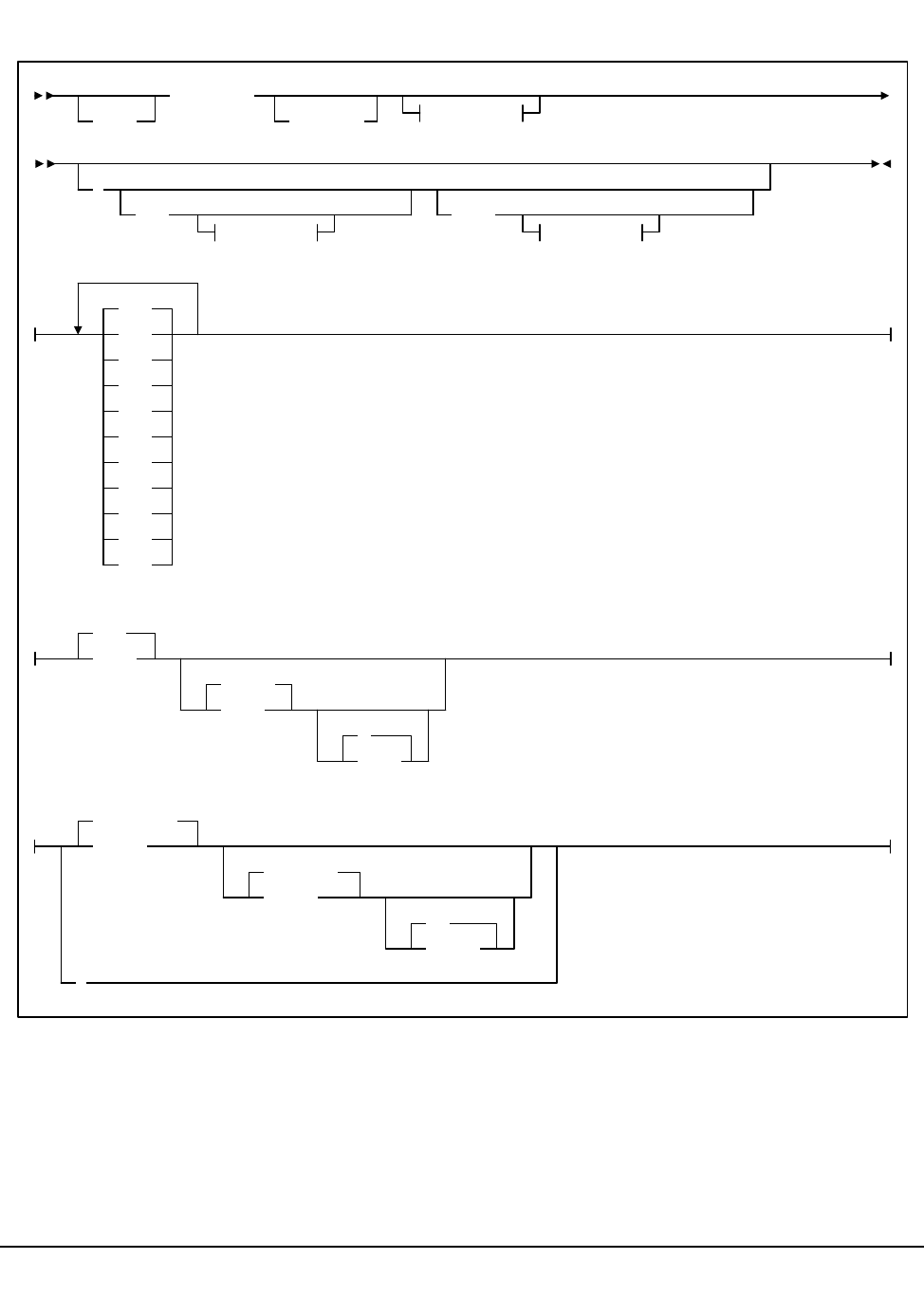
368 VM/HSC 6.0 System Programmer’s Guide
1st ed., 6/30/04 - 312579601
SCP Trace Formatter Utility
EXEC
optionally specified to invoke the EXEC.
SLUETRAC
initiates the SLUETRAC EXEC.
EXEC spoolid events
(
IN= OUT=
infile outfile
ALL
DSP
EXT
I/O
IUC
MCK
PGM
RST
SIO
SVC
USR
ACS
infn
TRACE
inft
A
infm
ACSTRACE
outfn
LISTING
outft
A1
outfm
*
outfile:
infile:
SLUETRAC

Chapter 5. Problem Determination, Diagnostics, and Recovery 369
1st ed., 6/30/04 - 312579601
spoolid
indicates the VM spool id of the reader spool file containing the trace data. If neither
spoolid nor IN= is specified, the first non-held reader spool file of type PUN is
processed.
Note: IN= overrides specification of a reader spool file.
events
indicates which events are to be traced:
IN=
indicates input is from a CMS file. If IN= is not specified, a reader spool file is
assumed.
Note: This overrides the specification of a spoolid.
infn
the CMS filename of the input file. The default is ACS.
inft
the CMS filetype of the input file. The default is TRACE.
infm
the CMS filemode of the input file. The default is A.
OUT=
indicates the output file. If OUT= is not specified, a printer spool file is created.
outfn
the CMS filename of the output file. The default is ACSTRACE.
outft
the CMS filetype of the output file. The default is LISTING.
outfm
the CMS filemode of the output file. The default is A1.
*
indicates to direct the output to the terminal.
ALL
DSP
I/O
MCK
PGM
RST
SIO
SVC
USR
- all of the following events (this is the default)
- task dispatched EXT - external interrupt
- I/O interrupt IUC - IUCV instruction
- machine check interrupt
- program check interrupt
- restart interrupt
- Start I/O and Start I/O Fast
- SVC interrupt
- user (GTRACE) invocation

370 VM/HSC 6.0 System Programmer’s Guide
1st ed., 6/30/04 - 312579601
Supervisor Call (SVC) Functions
The SCP partially supports the following SVC functions. They are included here for use
when reading trace output. Documentation of the actual subfunctions supported is for
StorageTek internal purposes only.

Chapter 5. Problem Determination, Diagnostics, and Recovery 371
1st ed., 6/30/04 - 312579601
Table 20. SVC Functions
Refer to Table
Note Hex Decimal Function
(1)
(2)
(2)
(2)
(2)
(1)
(1)
(2)
00
01
02
03
04
06
08
09
0A
0B
0C
0D
0F
10
13
14
18
1B
21
22
23
24
28
29
2A
2B
2C
2E
2F
30
33
37
38
3C
3E
40
4C
53
57
63
6B
77
78
7A
7F
0
1
2
3
4
6
8
9
10
11
12
13
15
16
19
20
24
27
33
34
35
36
40
41
42
43
44
46
47
48
51
55
56
60
62
64
76
83
87
99
107
119
120
122
127
EXCP
WAI T
POST
EXIT
LIST GETMAIN
LINK
LOAD
DELETE
GET/FREEMAIN R
TIME
SYNCH
ABEND
ERROR EXCP
PURGE I/O
OPEN
CLOSE
DEVTYPE
OBTAIN
IOHALT
QEDIT/MGCR
WTO/WTOR
WTL
EXTRACT
IDENTIFY
ATTA CH
CIRB
CHAP
TTIMER
STIMER
DEQ
SDUMP
EOV
ENQ
ESTAE
DETACH
RDJFCB
ERDS
SMFWTM
DOM
DYNALLOC
MODESET
TESTAUTH
GET/FREEMAIN
ESR2 (LOAD)
SCPROUTE
Note:
• May cause SVRB to run (extra RQBLOK).
• Always causes SVRB to run (extra RQBLOK).

372 VM/HSC 6.0 System Programmer’s Guide
1st ed., 6/30/04 - 312579601
SCP GTRACE Emulation
The SCP emulates the following MVS GTRACE features:
1. The MVS GTRACE macro is supported, without alteration.
2. A Monitor Call (MC) program interrupt occurs when the GTRACE function is
invoked. The SCP program check handler recognizes and handles the Monitor Call
as a GTRACE event.
3. Up to 256 bytes of user data may be traced.
4. With most interrupts, the SCP dispatcher does not return to the interrupted task
immediately, but dispatches the next task in the priority queue. However, after a
monitor call program interrupt the interrupted task IS returned to immediately. If this
were not done, program flow would be artificially altered by the act of tracing.
5. The Format Id (FID) parameter is supported. It describes the internal format of the
trace record. The valid (decimal) FID ranges are:
1 <= user FID <= 80
81 <= system FID <= 255
Actual FIDs used by the SCP are:
The actual FID used by the HSC is passed to the HSC initialization routine
(SLSBINIT), and is recorded in the ACS SYSPROF file. The default FID is 23.
6. The Event ID (EID) parameter is supported. It describes the event as a subtype of the
Format ID.
It is specified as a 4-digit hexadecimal number, of which the left-most digit is the
monitor call class.
Table 21. FIDs Used by SCP
Decimal Hex Char Meaning
195 x’C3’ c’C’ IUCV event
196 x’C4’ c’D’ Dispatcher event
197 x’C5’ c’E’ External interrupt
201 x’C9’ c’T’ I/O interrupt
212 x’D4’ c’M’ Machine check interrupt
215 x’D7’ c’P’ Program interrupt
217 x’D9’ c’R’ Restart interrupt
226 x’E2’ c’S’ Start I/O
229 x’E5’ c’V’ Supervicor call interrupt
230 x’E6’ c’W’ Return from SVC

Chapter 5. Problem Determination, Diagnostics, and Recovery 373
1st ed., 6/30/04 - 312579601
The valid EID ranges are:
0 <= user EID <= x’3FF’
x’400’ <= system EID <= x’FFF’
The actual EID used by the SCP is x’400’, for all FIDs.
The actual EID used by the HSC is passed to the HSC initialization routine (SLSBINIT),
and is recorded in the ACS SYSPROF file. The default EID is x’E086’, corresponding to
user event x’086’.

374 VM/HSC 6.0 System Programmer’s Guide
1st ed., 6/30/04 - 312579601
HSC Internal Trace Table
The HSC itself has an internal trace table. It is pointed to by the contents of the 4-byte
field at offset x’40’ from the start of the LVT (LVTTBLK).
It is a wrap-around table, recording the last 256 events that occurred in the HSC
subsystem. There are more than 90 different types of events. Trace entries are 108 bytes
long. The data traced will be truncated in order to fit into the table entry.
Programs issue an SLSTRACE macro at important trace points. The routine that is called
by the macro checks to see if tracing of the caller’s software component has been enabled.
The internal trace table is always updated. If the caller’s component has been enabled (by
the HSC ‘TRACE’ command), then GTRACE will also be invoked to produce an external
trace record for later analysis.
Table 22. Format of HSC Internal Trace Table
Offset Length Description
Header - 16 bytes long:
+0 4 Identifier - ‘BTRC’
+4 4 Length of trace table
+8 1 Subpool number
+9 1 Protection key
+A 6 Reserved for future use
ENTRIES - 108 bytes long:
+0 2 Trace identifier
+2 5 Name of module cutting the record
+7 1 *Length of data area used
+8 2 Trace module offset
+A 1 *Flag bits
+B 1 *Sequence number of this record
+C 4 Trace TBLOK address
+10 4 Reserved
+14 88 Trace data from component
Note: These fields (*) do not apply to internal trace records.

Chapter 5. Problem Determination, Diagnostics, and Recovery 375
1st ed., 6/30/04 - 312579601
00B613F0. C2E3D9C3 00006C10 F1300000 00000000 | BTRC..%.1....... |
00B61400. 6550D3D9 E2D740BC 00DA0000 009DB6B8 | .&LRSP ......... |
00B61410. 00000000 4DF1F8F6 F0F1F1F5 F7F2D2F1 | ....(186011572K1 |
00B61420. F1F1F8F1 F1F0F0F3 40404040 4040F340 | 11811003 3 |
00B61430. 40404040 40F34040 40404040 F3404040 | 3 3 |
00B61440. 404040F3 40404040 4040F340 40404040 | 3 3 |
00B61450. 40F34040 40404040 F3404040 404040F3 | 3 3 3 |
00B61460. 40404040 4040F340 40404040 6551D3D9 | 3 ..LR |
00B61470. E2D740EC 01BC8000 009DB6B8 00000000 | SP ............. |
00B61480. D3D9D840 00000104 00300000 00000000 | LRQ ............ |
00B61490. 00000000 8CF0F0F1 F1F8F0F0 F0F0F0F0 | .....00118000000 |
00B614A0. F1F1F8F0 F0F0F000 9CD84DF9 621A1C20 | 1180000..Q(9.... |
00B614B0. TO 00B614BF. (X’00000010’ bytes)!!All bytes contain X’00’
00B614C0. 00045F18 00000000 00045D28 0000009D | ..¬.......)..... |
00B614D0. 00000098 00000000 6552D3D9 E2D740E0 | ...q......LRSP \ |
00B614E0. 05920000 009DB6B8 00000000 D3D9E2C5 | .k..........LRSE |
00B614F0. 000000E0 00300000 00000000 02055240 | ...\........... |
00B61500. 000000BC 0000000B 4DF1F8F6 F0F1F1F5 | ........(1860115 |
00B61510. F7F2D2F1 F1F1F8F1 F1F0F0F3 40404040 | 72K111811003 |
00B61520. 4040F340 40404040 40F34040 40404040 | 3 3 |
00B61530. F3404040 404040F3 40404040 4040F340 | 3 3 3 |
00B61540. 40404040 6550D3D9 E2D740BC 00DA0000 | .&LRSP ..... |
00B61550. 009DB6B8 00000000 4DF1F8F6 F0F1F1F5 | ........(1860115 |
00B61560. F7F2D2F1 F2F1F8F1 F2F0F0F3 40404040 | 72K121812003 |
00B61570. 4040F340 40404040 40F34040 40404040 | 3 3 |
00B61580. F3404040 404040F3 40404040 4040F340 | 3 3 3 |
00B61590. 40404040 40F34040 40404040 F3404040 | 3 3 |
00B615A0. 404040F3 40404040 4040F340 40404040 | 3 3 |
00B615B0. 6551D3D9 E2D740EC 01BC8000 009DB6B8 | ..LRSP ......... |
00B615C0. 00000000 D3D9D840 00000104 00300000 | ....LRQ ........ |
00B615D0. 00000000 00000000 8CF0F0F1 F1F8F0F0 | .........0011800 |
00B615E0. F0F0F0F0 F1F1F8F0 F0F0F000 9CD84DF9 | 00001180000..Q(9 |
00B615F0. 621A1C20 00000000 00000000 00000000 | ................ |
00B61600. 00000000 00045F18 00000000 00045D28 | ......¬.......). |
00B61610. 0000009D 00000098 00000000 6552D3D9 | .......q......LR |
00B61620. E2D740E0 05920000 009DB6B8 00000000 | SP \.k.......... |
00B61630. D3D9E2C5 000000E0 00300000 00000000 | LRSE...\........ |
00B61640. 02055160 000000BC 0000000C 4DF1F8F6 | ...!........(186 |
00B61650. F0F1F1F5 F7F2D2F1 F2F1F8F1 F2F0F0F3 | 011572K121812003 |
00B61660. 40404040 4040F340 40404040 40F34040 | 3 3 |
00B61670. 40404040 F3404040 404040F3 40404040 | 3 3 |
00B61680. 4040F340 40404040 6550D3D9 E2D740BC | 3 .&LRSP . |
00B61690. 00DA0000 009DB6B8 00000000 4DF1F8F6 | ............(186 |
00B616A0. F0F1F1F5 F7F2D2F1 F3F1F8F1 F3F0F0F3 | 011572K131813003 |
Figure 23. HSC Internal Trace Table Example

376 VM/HSC 6.0 System Programmer’s Guide
1st ed., 6/30/04 - 312579601
HSC TRACE Command
The HSC TRace command enables or disables tracing of events in selected HSC
components.
It uses GTRACE to perform the actual tracing. The SCP TRACE command must have the
“USR” event enabled for any trace output to result.
For a detailed description of how to use the HSC TRACE command, refer to the HSC
Operator’s Guide.
Format of HSC GTRACE USR Records
Table 23. HSC GTRACE USR Records
Offset Length Description
+C 2 Trace identifier
+E 5 Name of module issuing SLSTRACE macro
+13 1 Length of data area used
+14 2 Trace module offset
+16 1 Flag bits
X’80’ Data truncated
X’40’ Allow GTRACE recording
X’20’ First pass
+17 1 Sequence number of this record
+18 4 Trace TBLOK address
+1C 4 Reserved
+20 1-224 Trace data from component
Notes:
• GTF REcord size = 256 Bytes
• HSC Record size may be larger than 256 Bytes
• One HSC record may require more than one GTF record.
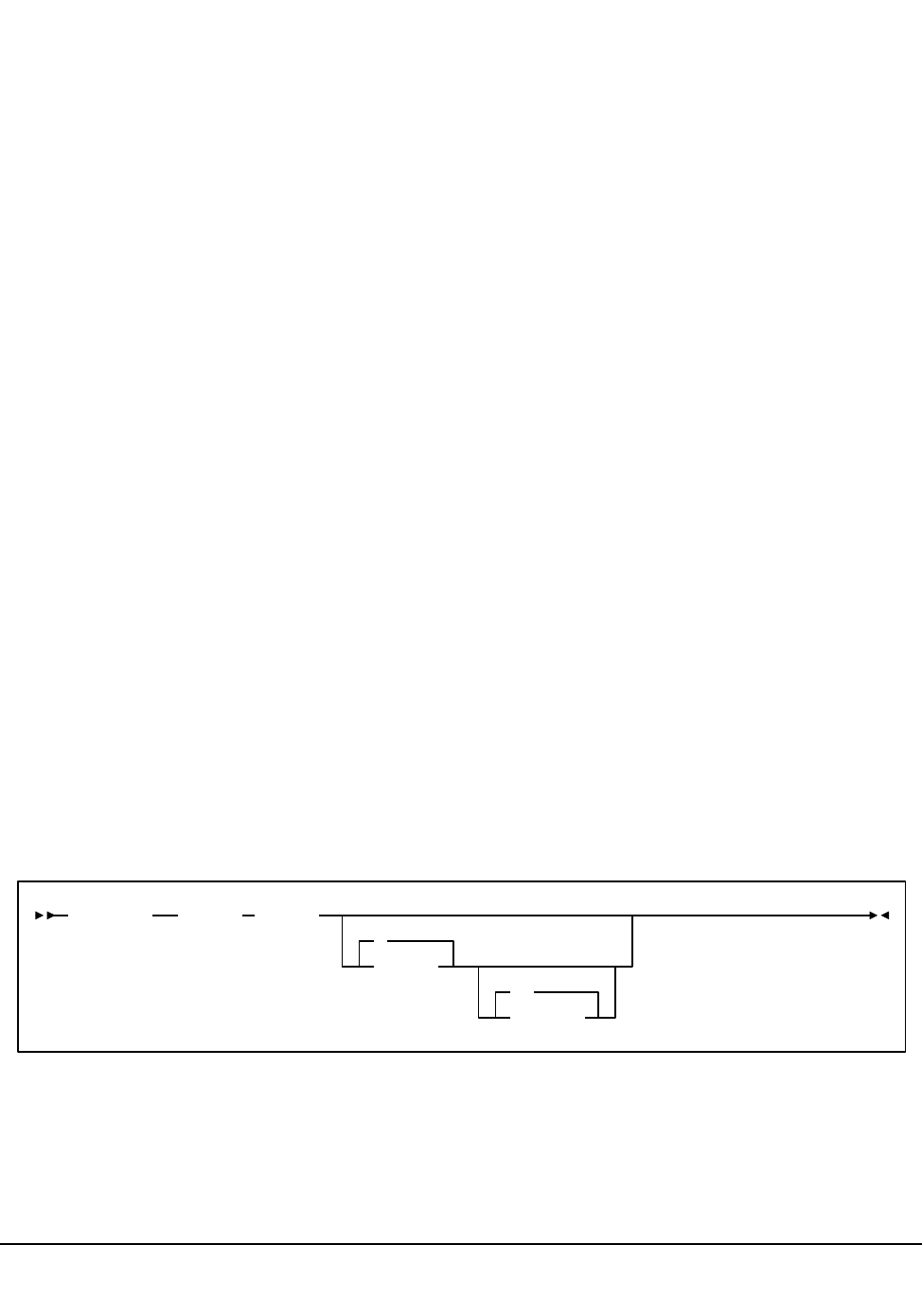
Chapter 5. Problem Determination, Diagnostics, and Recovery 377
1st ed., 6/30/04 - 312579601
Diagnostic Commands
VM (CP) Commands
The CP commands listed in “VM (CP) Debug Commands” on page 349 are very useful in
diagnosing a problem. For maximum effectiveness, they should be used in conjunction
with the SCP’s diagnostic subsystem commands.
SCP Debug Mode
The SCP may operate in a special ‘‘debug’’ mode, initiated by some of the commands of
the SCP diagnostic subsystem.
The debug mode is special in the following ways:
• When entering debug mode, the SCP issues the CP command SET RUN OFF. After
this, when the virtual machine enters a CP READ state, the virtual machine stops and
does not proceed until a CP BEGIN command is issued.
• A flag is set in the CVT to indicate that debug mode is active.
• If the SCP command STOPSCP is issued, control will return to CMS without a
re-IPL.
• Debug mode is terminated by the diagnostic command ‘=NODEBUG’.
Setting Initialization Sequence Break-Points
Sometimes, it is useful to setup program break-points that would be reached before the
command interface is enabled.
After the ACS EXEC loads the program modules into storage, the locations of the
break-points will be determined, and the CP PER command will be used to set stops for
those locations. After all break-points have been set, the CP QUERY PER command is
issued to display what has been set. When the SCP is initialized, it will be in the special
‘‘debug’’ mode.
To set such break-points, start the SCP with the following command:
epname
the name of a known entry point. It is either named in the map within any
SLKNUCxx module or there is a CDE structure for the name.
ACS INIT (BREAK epname
0
offset
.1
.length

378 VM/HSC 6.0 System Programmer’s Guide
1st ed., 6/30/04 - 312579601
If the name is known, it will be located in storage. It will be brought into storage if it
was not there before.
If epname is not specified, the current traces are displayed.
offset
the optional offset from the address of epname at which to set a breakpoint using CP
PER. The default is 0.
.length
the optional length of the breakpoint. The default is 1.
Note: length must be preceded by a period with no space between offset and the
period.
An example of setting break-points follows:
ACS INIT (BREAK SLKDMOP 5E.1C
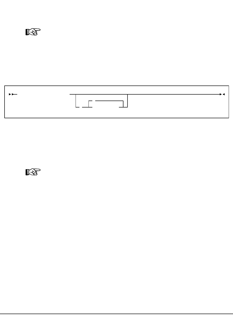
Chapter 5. Problem Determination, Diagnostics, and Recovery 379
1st ed., 6/30/04 - 312579601
SCP Diagnostic Subsystem Commands
These commands are provided for use when diagnosing a problem with a ‘‘live’’ system.
Any other use may result in indeterminate conditions.
Note: It is recommended that StorageTek support personnel be contacted before using
diagnostic subsystem commands.
These commands are only valid when entered from the ACS service machine’s virtual
console.
Enabling the Diagnostic Subsystem
Issue the following SCP operator command:
This command activates the diagnostic subsystem and enables the use of some special
commands.
prefixchar is a command prefix indicating that the command is to be handled by the
diagnostic subsystem. The default prefix is ‘‘=’’ (equal sign), but may be set to any
character that does not conflict with use by other subsystems (for example, the HSC).
Note: The prefix character cannot be changed during a session. The SCP must be recycled
and the new prefix character specified with the subsequent SUBSYS command.
The commands below are part of the diagnostic subsystem. The prefix character should be
that described above.
=DEBUG - enter the ‘‘debug’’ mode.
=NODEBUG - exit the ‘‘debug’’ mode.
=DDICT - return the data dictionary definition of a field.
=HPER - set multiple break-points using the CP PER command.
=WHERE - display the storage location for a given program module.
=DEBUG
This diagnostic command initiates the special ‘‘debug’’ mode. ‘CP SET RUN OFF’ is also
executed.
=
the command character for the DIAG subsystem. The default is ‘‘=’’, but may be set
to any character by the SUBSYS command that started the subsystem.
SUBSYS DIAG SLKSBDIA
=
(prefixchar

380 VM/HSC 6.0 System Programmer’s Guide
1st ed., 6/30/04 - 312579601
=NODEBUG
This diagnostic command terminates the special ‘‘debug’’ mode. ‘CP SET RUN ON’ is
also executed.
=
the command character for the DIAG subsystem. The default is ‘‘=’’, but may be set
to any character by the SUBSYS command that started the subsystem.
=DDICT
This diagnostic command displays data dictionary information describing an SCP or HSC
data area fieldname.
The information returned is the assembler definition of the field with the DSECT name
and the offset from the DSECT.
‘CP SET RUN OFF’ is executed, and the SCP debug mode is entered. The diagnostic
command ‘=NODEBUG’ terminates the debug mode.
=
the command character for the DIAG subsystem. The default is ‘‘=,’’ but may be set
to any character by the SUBSYS command that started the subsystem.
fieldname
the name of a field in an SCP or HSC data structure.
Examples:
Issuing the command:
=DDICT LVTSSCVT
Results in:
LVT: LVTSSCVT+000C DS A
Issuing the command:
=DD ATPARM
Results in:
ATNAME: ATPARM +0018 DS (16)A
Issuing the command:
=DD CMDTOKS
Results in:
CMDTOKS: CMDPLIST+00CC DS (32)XL(4)

Chapter 5. Problem Determination, Diagnostics, and Recovery 381
1st ed., 6/30/04 - 312579601
=HPER
This diagnostic command sets one or more break-points for a list of named modules and
offsets. The CP QUERY PER command is then issued to display the current program traps
in effect.
Note: In the VM/XA environment, CP PER and QUERY PER are synonyms for the CP
TRACE and QUERY TRACE commands.
‘CP SET RUN OFF’ is executed, and the SCP debug environment is entered. The
diagnostic command ‘=NODEBUG’ terminates the debug environment.
=
the command character for the DIAG subsystem. The default is ‘‘=,’’ but may be set
to any character by the SUBSYS command that started the subsystem.
epname
the name of a known entry point. It is either named in the map within any
SLKNUCxx module or there is a CDE structure for the name.
If the name is known, it will be located in storage. It will be brought into storage if it
was not there before.
If epname is not specified, the current traces are displayed.
offset
the optional offset from the address of epname at which to set a breakpoint using CP
PER. The default is 0.
.length
the optional length of the breakpoint. The default is .1.
Note: length must be preceded by a period with no space between offset and the
period.
For example, issuing the command:
=HPER slsbinit slkode 54.8

382 VM/HSC 6.0 System Programmer’s Guide
1st ed., 6/30/04 - 312579601
Results in CP QUERY PER output. The following output is for VM/SP, VM/SP
HPO, and VM/ESA 370.
1 INSTRUCT RANGE addr TERMINAL NORUN CMD * FUNC=SLSBINIT OFFSET=000000
2 INSTRUCT RANGE addr!addr TERMINAL NORUN CMD * FUNC=SLKODE OFFSET=000054
The following output is for VM/XA and VM/ESA.
=WHERE
This diagnostic command displays the module location of a named program module (and
the date/time of last assembly), or the module name which contains a given address.
‘CP SET RUN OFF’ is executed, and the SCP debug environment is entered. The
diagnostic command ‘=NODEBUG’ terminates the debug environment.
=
the command character for the DIAG subsystem. The default is ‘‘=,’’ but may be set
to any character by the SUBSYS command that started the subsystem.
epname
the name of a known entry point. It is either named in the map within any
‘SLKNUCxx’ module or there is a CDE structure for the name.
If the name is known, it will be located in storage. It will be LOADed into storage if
it was not there before.
address
any storage address. If it is within a known module, the module and entry point
names and the offsets from each will be returned.
NAME INITIAL (ACTIVE)
1 INSTR PSWA addr
TERM NOPRINT NORUN SIM
SKIP 00000 PASS 00000 STOP 00000 STEP 00000
CMD * FUNC=SLSBINIT OFFSET=00000000
2 INSTR PSWA addr-addr
TERM NOPRINT NORUN SIM
SKIP 00000 PASS 00000 STOP 00000 STEP 00000
CMD * FUNC=SLKODE OFFSET=00000054

Chapter 5. Problem Determination, Diagnostics, and Recovery 383
1st ed., 6/30/04 - 312579601
Examples:
Issuing the command:
=WHERE SLSBINIT 23FDF0
Results in the messages:
SLKOWH671I Module SLSBINIT at address 23FD50 compiled 09/20/88 14.20
SLKOWH674I Address 23FDF0 = EP : SLSBINIT +0000A0
SLKOWH674I Address 23FDF0 = CSECT: SLSBINIT +0000A0
HSC Diagnostic Commands
The following HSC diagnostic commands are provided:
• LIst command
• Display command.
The HSC LIst command is provided for diagnostic support for the HSC. Use this
command under the direction of StorageTek support personnel.
LIst Command
The LIst command is used to display an HSC data structure.
Syntax
Parameters
LIst
initiates the LIst command.
data-structure
specifies the name of a single HSC data structure. It may be any one of the following:
LVT Library Vector Table
BCVT Initialization/Termination Communications Vector Table
CCV CAP Communication Vector Table
DCV Database Server Communications Vector Table
FCVT Configuration Control Communication Vector Table
HCVT Host Communication Vector Table
JCVT Job Processing Communication Vector Table
LCVT LMU Communication Vector Table
MCVT Mount/Dismount Vector Table
OCVT Operator Command Vector Table
QVT Ascomm Vector Table
RCVT Recovery Communication Vector Table
UCT Utilities Communication Vector Table
|VCT Volume Cell Communication Table

384 VM/HSC 6.0 System Programmer’s Guide
1st ed., 6/30/04 - 312579601
address
specifies a hexadecimal address of memory.
size
specifies the amount of memory (in decimal) to display. The default size is 16.
DISPLAY Command
The HSC Display command offers several options that are useful for diagnostic purposes.
For more information on the Display command and its uses for diagnostics, refer to the
HSC Operator’s Guide.

Chapter 5. Problem Determination, Diagnostics, and Recovery 385
1st ed., 6/30/04 - 312579601
CDS Recovery Capabilities
Capabilities to recover the CDS from certain hardware and software failures are inherent
in the HSC. CDS recovery capabilities include:
• dynamic recovery of the control data set
• control data set error diagnostics
• initializing/running on one copy of the control data set
• switching to another copy of the control data set
• control data set integrity during BACKup and RESTore
• detecting mismatch of control data sets
Additional recovery information is available in the HSC Operator’s Guide pertaining to
the following topics:
• cartridge recovery
• errant cartridge recovery
• switch to standby LMU
• automatic downward switch of the host-to-host communication method level
• starting the HSC at the base service level
Control Data Set Recovery
Dynamic Recovery of the Control Data Set
At HSC installation, specifying additional control data sets, secondary and standby, in the
LIBGEN SLIRCVRY macro indicates that these additional copies of the control data set
are maintained by the HSC during library operation and kept on DASD. In addition, a CDs
operator command provides you with the capability to enable or disable any of the various
control data sets. An auto-enable function of the command sets the automatic switch
capability of the HSC to automatically switch operation to another control data set.
If a failure occurs accessing the primary control data set, the HSC automatically switches
operation to the secondary control data set. At the time that the switch to the secondary
control data set occurs, the standby control data set becomes valid. After library operation
continues with the secondary control data set, should the secondary control data set
become inaccessible, the standby control data set is accessed and used by the HSC to keep
the library operating.
Note: If the primary and secondary control data sets fail simultaneously, without sufficient
time for the HSC to make the standby data set valid and accessible, HSC operation is
impaired.
These backup data sets replace a failing control data set; however, they retain their original
data set name.

386 VM/HSC 6.0 System Programmer’s Guide
1st ed., 6/30/04 - 312579601
When access to a failing data set is restored, you must run the BACKup and RESTore
utilities to restore the integrity of the failed data set. An alternative method is to use the
CDs command, specifying the Enable parameter to append the data set again to the end of
the Active CDS List.
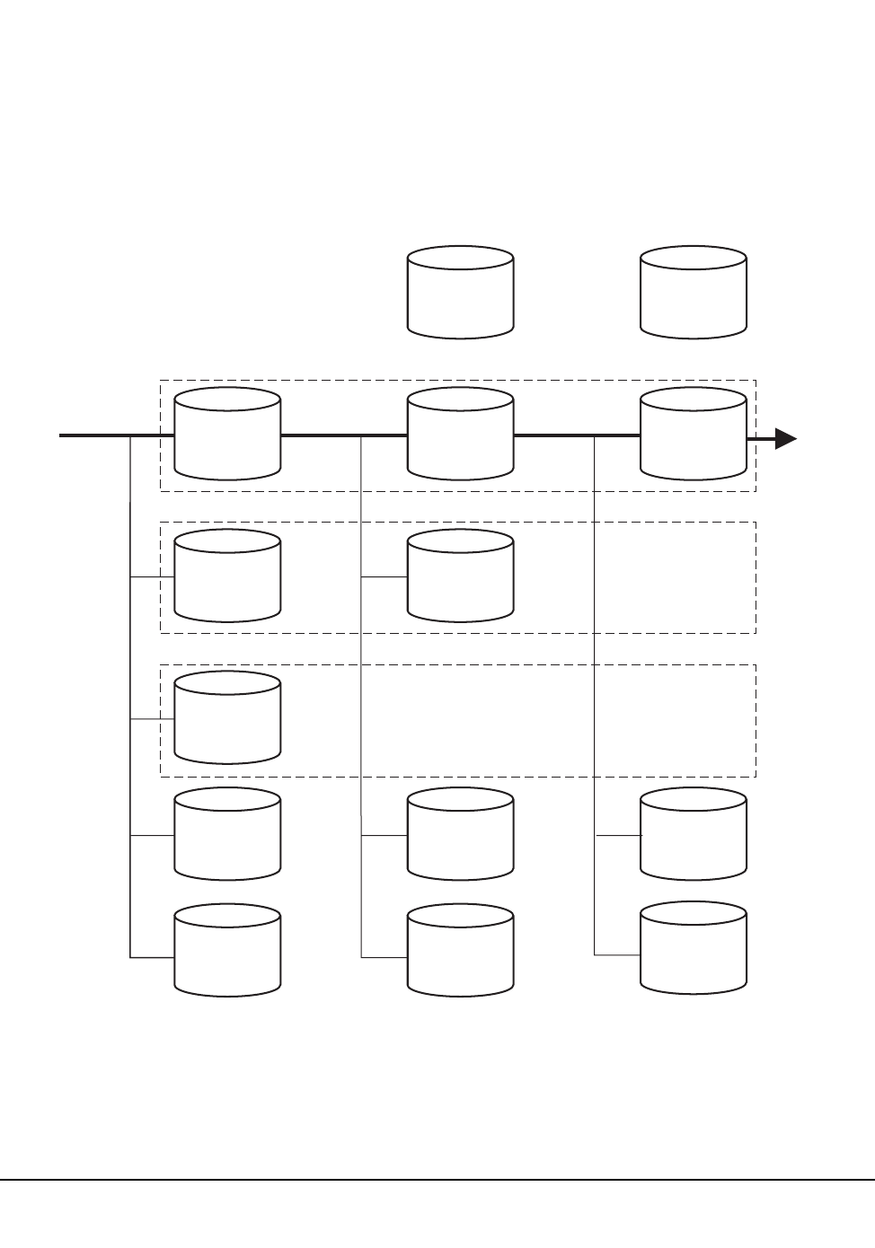
Chapter 5. Problem Determination, Diagnostics, and Recovery 387
1st ed., 6/30/04 - 312579601
Figure 24 illustrates the built-in recovery scheme for the control data sets.
CONTROL
DATA SET
1
CONTROL
DATA SET
2
PRIMARY CONTROL DATA SET
SECONDARY CONTROL DATA SET
STANDBY CONTROL DATA SET
CONTROL
DATA SET
3
DATA SET
1DATA SET
2
CONTROL
DATA SET
2
CONTROL
DATA SET
3
CONTROL
DATA SET
3
JOURNAL JOURNAL
JOURNAL
JOURNAL
JOURNAL
JOURNAL
HSC
EXECUTION
INITIAL
CONTROL
DATA SET
CONFIGURATION
AT FAILURE OF
PRIMARY CONTROL
DATA SET, HSC
OPERATES ON
SECONDARY DATA SET
STANDBY DATA SET
IS MADE VALID
FOR USE
AT FAILURE OF THE
SECONDARY CONTROL
DATA SET, THE HSC OPERATES
ON THE STANDBY DATA SET
PROVIDED THAT STANDBY
DATA SET WAS OPERATIONAL
- FAILED -
- FAILED -
C29343
Figure 24. Control Data Set Recovery Scheme

388 VM/HSC 6.0 System Programmer’s Guide
1st ed., 6/30/04 - 312579601
All HSCs in operation must be stopped to perform the restore operation.
If the three control data sets fail, the journal(s) can be used to restore a valid control data
set.
Refer to “Backup Utility” on page 211 for detailed information about running the
BACKup utility. Refer to “Restore Utility” on page 276 for detailed information about
running the RESTore utility.
Control Data Set Error Diagnostics
Numerous messages are provided to permit you to diagnose problems pertaining to the
control data sets. The messages describe error circumstances including:
• block mismatches between copies of the control data sets
• missing DD statements required for control data set initialization
• various backup and restore actions
• discrepancy block information, and other pertinent diagnostic information.
Refer to the HSC Messages and Codes Guide for more information about messages
encountered that pertain to the control data sets and the BACKup and RESTore utilities.
Control Data Set Processes
Several important processes are available to you for recovery purposes. These are
designed to permit you to keep your library running when there are apparent problems
with the primary control data set. Processes include how to:
• initialize and run the HSC on one copy of the control data set
• switch to any backup copy of the control data set
• switch the control data set in a multi-host environment.
Initializing/Running the HSC on One Copy of the Control Data Set
You have the option of initializing and running the HSC on only one copy of the control
data set. With the available PARMLIB control statements, you can specify secondary and
standby control data sets; however, if for any reason, the HSC can run on only one of the
control data sets, the HSC continues to run normally.
The HSC has the capability of determining which of any number of control data sets are
valid and consequently chooses a valid data set with which to continue operation.
It is highly recommended that you initialize, in addition to the primary control data set, a
secondary and a standby control data set. With these data sets, you can recover from
problems with the primary control data set.

Chapter 5. Problem Determination, Diagnostics, and Recovery 389
1st ed., 6/30/04 - 312579601
Switching to a Backup Copy of the Control Data Set
If you have initialized your HSC subsystem with the additional backup copies of the
control data set, you can dynamically switch operation to any one of the copies without
affecting the HSC and library operation.
With an operator command, you can enable or disable specific copies of the control data
set. When a copy of the CDS is disabled, the specified control data set is taken offline
while any of the backup control data sets are brought online; the HSC continues to run the
the library installation during the switch. When a new control data set is brought online, all
work within a library complex needing the control data set halts until the switch function
completes. Depending on the size of the complex, this switching time can take a few
minutes. However, this is a better alternative than an HSC shutdown and subsequent
restore of data sets, especially in a multi-host environment.
Operator commands are available to display the status of current control data sets or to
enable/disable/autoenable any copy of the control data set. Refer to the HSC Operator’s
Guide for detailed information about the commands.
Switching the Control Data Set in a Multi-Host Environment
In a multi-host environment, the HSC automatically provides communications to all hosts
when a control data set switch has occurred. For this communications performance to
occur, the proper hardware and software must exist in the library installation and the
parameter data set must specify parameters invoking utilization of the hardware and
software.
Control Data Set Integrity During Restore
To take advantage of the recovery capabilities of the HSC during the restore operations, it
is necessary to ensure that you have initialized a standby control data set.
Refer to Chapter 7, ‘‘Allocating and Initializing Control Data Sets’’ in the HSC
Installation Guide for detailed information about installing the HSC and initializing
control data sets.
Detecting Mismatch of Control Data Sets
Control data set mismatch occurs when the HSC has determined that the primary and
secondary (or shadow) control data sets are not synchronized. Normally, the HSC
automatically determines which copy of the control data set is valid and switches
operation to that data set.
The recovery performed by the HSC is transparent to you, except for the issuance of
appropriate messages to the operator. Through the messages, the operator is made aware
of the switching that has occurred.
In cases where the HSC cannot determine which control data set is valid, you must run the
BACKup and RESTore utilities to recover the data sets. Refer to “When CDS Copies Are
Split Among Hosts After an Error” on page 213 for some special considerations
concerning control data sets.

390 VM/HSC 6.0 System Programmer’s Guide
1st ed., 6/30/04 - 312579601
Recommended Recovery Actions
Once you are aware that a switch of the control data set has occurred, it is recommended
that the following actions be taken:
1. Run the BACKup utility.
2. Retain a backup copy of each control data set for diagnostic purposes.
3. Run the RESTore utility.
4. If DASD hardware errors are found, reallocate valid control data sets to a good
storage device.
If you are unsuccessful in recovering from mismatch errors, contact StorageTek Software
Support.
Information Required for StorageTek Diagnosis
To aid diagnosis, collect the following information:
• backup copies of the primary, secondary, and standby control data sets at the time of
the error
• console logs for a period of one hour before the mismatch condition was detected.

Chapter 5. Problem Determination, Diagnostics, and Recovery 391
1st ed., 6/30/04 - 312579601
Dump Processing
The following dump processing topics are discussed below:
• Type of dumps supported
• How to request a dump
• What to do when a dump occurs
• Dump analysis using SLUIPCS
• Major SCP data relationships
• Diagnostic techniques
• Common dump analysis tasks.
Type of Dumps Supported
In order to use IPCS for dump analysis, dumps must be produced via the CP ‘VMDUMP’
command (or diagnose code x’94’).
The dump ‘‘format’’ for this product is ‘SLK’.
Printed dumps produced by the CP DUMP command are of limited benefit, and consume
too much spool space and paper.
How to Request a Dump
Dumps may be produced in several ways:
• The ‘SDUMP’ function may be invoked by any program in the SCP or the HSC. This
is usually done in an ESTAE recovery routine that was called after an error occurred.
The dump title supplied to the SDUMP becomes the dump title passed to the CP
diagnose (x’94’) function that actually creates the dump spool file.
• The SCP operator command ‘DUMP’ may be used to produce a dump at any time.
The comments supplied to the command become the dump title passed to the CP
diagnose (x’94’) function that actually creates the dump spool file.
• The ‘CP VMDUMP’ command may be used from the connected console of the ACS
service machine to create a dump.
Caution: If this technique is used, you MUST USE THE FOLLOWING
PARAMETERS. Any other FORMAT will result in a dump that cannot be processed
by the special dump analysis tools provided with the product.
(Get into CP READ state by pressing the PA1 key)
VMDUMP 0.END TO userid FORMAT SLK *your!comments!go!here
The comments may be anything you choose.

392 VM/HSC 6.0 System Programmer’s Guide
1st ed., 6/30/04 - 312579601
What to do When a Dump Occurs
When a VM HSC dump occurs, it is sent as a CLASS V spool file to the virtual machine
defined by the current DUMPOPTS setting. Dump files are large and can have a negative
impact on system spool space; they should be processed as soon as possible after they
occur.
The following steps should be taken when a dump occurs:
1. Move the CONSLOG and dump spool files to the dump processing machine’s virtual
reader.
2. Note the reason for the dump.
3. Load the CONSLOG and dump onto MAINTSTK’s IPCS disk.
4. Call StorageTek Software Support.
5. Move requested material to tape and ship to StorageTek.
Move Dump and CONSLOG to Dump Processing Machine’s Virtual Reader
If no DUMPOPTS command had been issued, then the dump will be found in STKACS’s
virtual reader.
Move it to the appropriate machine’s virtual reader by issuing the following command
from STKACS’s virtual console:
CP TRANSFER RDR CLASS V TO userid
If the initial settings of CONSLOG were in effect, then the CONSLOG will be found in
STKACS’s virtual reader as a class C PRT file with the name SLS.CONSOLE.LOG.
Move it to the same machine’s virtual reader by issuing the following command from
STKACS’s virtual console:
CP TRANSFER RDR CLASS C TO userid
Note Reason For Dump
Make a note of the reason the dump was created. If the dump was due to an ABEND, then
the ABEND code and reason code are kept in the spool file’s NAME and TYPE fields.
Issue the following command from MAINTSTK’s virtual console to display this
information:
QUERY RDR CLASS V ALL
Below is an example of the response for a dump taken due to an ABEND with a user
ABEND code of 1096 and a reason code of 4500450.
ORIGINID FILE CLASS RECORDS CPY HOLD DATE TIME NAME TYPE
STKACS 0074 V DMP 00001285 001 NONE 02/27 18:23:46 U1096!4500450

Chapter 5. Problem Determination, Diagnostics, and Recovery 393
1st ed., 6/30/04 - 312579601
Load Dump and CONSLOG Onto Disk
Load the dump spool file onto MAINTSTK’s IPCS disk. Ensure that MAINT’s 193 disk is
ACCESSed. MAINTSTK normally has a LINK to this disk in its directory entry.
To access the disk, issue the following command from MAINTSTK’s virtual console:
ACCESS 193 B
Issue the following command to load the first dump spool file onto disk:
SLUIPCS LOAD
A message is issued providing the name of the disk file created. This disk file has a name
of the form PRBnnnnn DUMP.
Load the related CONSLOG file onto MAINTSTK’s IPCS disk (normally accessed as the
‘‘K’’ disk). The example below loads the CONSLOG, whose spool file number is 70, onto
MAINTSTK’s IPCS disk:
RECEIVE 70 PRBnnnnn CONSLOG K
Call StorageTek Software Support
Call StorageTek Software Support using the telephone number provided in the Requesting
Help from Software Support guide. The remote diagnostician will request the following
information:
• Your StorageTek site location ID
• ABEND code and reason code
• Dump title
• Maintenance level of the VM HSC (for example, PUT 9301)
• Operating system name, release, and maintenance level (for example, VM/ESA,
Release 2, Service Level 0000). This information can be obtained by issuing the CP
command:
QUERY CPLEVEL
Move Problem Materials to Tape
StorageTek Software Support may require that the problem materials be copied to tape and
shipped to them for detailed analysis. Copy the materials to tape using the VMFPLC2
CMS command. Details on using VMFPLC2 can be found in the IBM Service Guide for
VM/SP and VM/SP HPO, Release 6, or the IBM Installation and Service manual for
VM/XA SP, VM/ESA, and VM/ESA 370.
Normally, Software Support requires the following materials:
• The dump (PRBnnnnn DUMP)
• The related CONSLOG (PRBnnnnn CONSLOG)
• The software maintenance log (SMS2000 VMFSVLOG)

394 VM/HSC 6.0 System Programmer’s Guide
1st ed., 6/30/04 - 312579601
Below is an example of the VMFPLC2 commands normally used to copy the problem
materials onto a tape mounted at virtual address 181:
VMFPLC2 DUMP PRBnnnnn * *
VMFPLC2 DUMP SMS2000 VMFSVLOG *
VMFPLC2 WTM 2
Dump Analysis Using SLUIPCS
Normally, dump analysis is performed by a StorageTek Software Support Representative.
However, the facilities described in this section are available to all users.
The SLUIPCS CMS command supplied by StorageTek utilizes the dump processing
facilities native to the VM release on which it executes. Under VM/SP, VM/SP HPO, and
VM/ESA 370, SLUIPCS uses Interactive Problem Control System (IPCS) facilities; under
VM/XA SP and VM/ESA, SLUIPCS uses the Dump Viewing Facility (DVF).
When SLUIPCS SCAN is specified, one of the following interactive dump analysis
(SCAN) environments is established:
• DUMPSCAN - VM/XA SP and VM/ESA
• IPCSSCAN - VM/SP and VM/SP HPO, Release 6, and VM/ESA 370
After entering the SCAN environment, you may invoke any of the environment’s IBM or
StorageTek supplied subcommands. The following IBM manuals describe the IBM
subcommands that may be used in the SCAN environment:
•VM/SP and VM/SP HPO Release 6 -- IPCS Guide and Reference
•VM/ESA 370 Release 1 -- IPCS Guide and Reference
•VM/XA SP and VM/ESA -- Dump Viewing Facility Operation Guide and Reference
StorageTek provides the following specialized subcommands for the SCAN environment:
Table 24. Subcommands for the SCAN Environment
Subcommand Function
EX Execute CMS command
FIND Display address of a named data structure
PSW Display PSW
STAT Display PSW, regs, clocks, and dump title
TASK Display TBLOK address(es) for a named task
TRB Display register save area traceback
TTE Display a trace table entry
VIEW Display a named data structure
WA Display module name at specified address
WN Display starting address of specified module name

Chapter 5. Problem Determination, Diagnostics, and Recovery 395
1st ed., 6/30/04 - 312579601
To terminate the SCAN environment, use the END subcommand.
To format and print data areas and control blocks, issue the SLUIPCS PRINT command.
The user is prompted for StorageTek-defined print options.
SLUIPCS SCAN Subcommands
These StorageTek-supplied SCAN subcommands ‘‘know’’ about SCP and HSC data
structures and module locations.
VIEW
The VIEW subcommand displays a data structure, and saves its last resolved dump
address.
After supplying or otherwise resolving a structure address, the VIEW subcommand may
be issued with just a structure name. In this case, the address that was last used for that
structure will be used.
VIEW CVT
VIEW CCVT
VIEW NUCON
VIEW MTT
VIEW STORMAN
VIEW LVT
VIEW struct!name
VIEW struct!name address
VIEW struct!name label!name
VIEW struct!name @ label!name
VIEW struct!name in label!name
VIEW struct!name

396 VM/HSC 6.0 System Programmer’s Guide
1st ed., 6/30/04 - 312579601
Table 25. VIEW-able SCP Data Structures
Data Structures
ATTPARM *CCVT CDE CHANCELL CIB
CMDPLIST CPIB CSWORD CUCELL *CVT
DAB DECB DEVBLOK ECB ERREC
EXDAT EXTDESC FREANC GRFA IEZCOM
IHADCB IOBLOK IQE IRT IUB
JBLOK JFCB JWA MCBLOK MSGEL
*MTT NEWTQE *NUCON ORIGID PSWORD
QSGET RQBLOK RTM1PARM RTM1WA RTM2WA
SCB SFCB SMFHDR *STORMAN STQENT
SVC006 SVC011 SVC012 SVC034 SVC036
SVC046 SVC046M SVC047 SVC047M SVC060
SVC107 SVC119 SVICB SYSTIOT TBLOK
TIMECONV TQE TRELAT TSEL TTE
XINT
Table 26. VIEW-able HSC Data Structures
Data Structures
ACSINT ACT AEDL AEDT ALDL
ALRB AOPTP ASRQWA AVOLU BCPTAB
BCV BITE BLOG BLOS BPRMLST
BSVT BUXVT CCV CESETPL CJCOMM
CJSMF CNCOMM CNSMF CRB CSNTR
CTR CVT DAC DBB DBPARAM
DCE DCH DCV DELTAWK DES
DHB DIT DJB DJLR DPV
DVT EACT ECVT EJRB EJST
ELCVT ELMT ELRB EMSG ESEPWA
EWRPY EWTO FCVT FDRVT FESTAEPL
FH2HB FSTNT HCVT HST IEESMCA
IEFJESCT IEFJSCVT IEFUCBOB IEZDEB IHAASCB

Chapter 5. Problem Determination, Diagnostics, and Recovery 397
1st ed., 6/30/04 - 312579601
IHAASCB IHAPSA IKJTCB ILLT ITCA
JCVT JPIAL JPIB JPMESG LASP
LBM LBR LCB LCCD LCCW
LCF LCS LCT LCVT LDBK
LDW LEPL LHB LHQ LHRQ
LIQE LITC LLG1 LLG2 LLG3
LLG4 LLSB LMDT LME LPVL
LPVS LQC LRPL LRSE LRSP
LRT LSB LSL LSLM LSR
LSSE LST LSTB LSWT LTAB
LTC B LTEB LURB *LVT MAIL
MCVT MDQE MEPL MFCR MHIB
MHTH OCDE OCRE OCVT ODACS
ODCAP ODLSM ODSFT OFFLDWK OLHDR
ONLSTP ONTAB ORQD ORQL ORQS
ORQX OSHDR OSMLSM OSVSTA PSWIT
QEPL QFCE QFCT QMTB QRWK
QTIP QUAB QVT RACB RCVT
REPL RITC RITO RITP RITT
RL00 RL01 RPAURE RPCLPL RPEMAT
RPITSK RPRESV RRPL RT00 RT01
RWPLIST SCPOOLWK SCPOOLX SDEBUG SLSID
SLX TMSIB TRCB VAR VAT
VCAM VCMASK VCSCNIWK VCT VITT
VPLCFRE VPLCGET VPLCSCN VPLCSTA VPLLSEL
VPLSDEL VPLSPRE VPLSREF VPLSSEL VPLSSTA
VPLVERT VPLVINS VPLVREF VPLVSEL VSLB
VSSP VTQB VTQE VUESTAE WMLIST
Note: “*” indicates that “VIEW” implicitly knows the structure’s location.
Table 26. VIEW-able HSC Data Structures

398 VM/HSC 6.0 System Programmer’s Guide
1st ed., 6/30/04 - 312579601
FIND
FIND is identical to the VIEW command, except that only the address of the found
structure is displayed. It is useful when following pointer chains to a structure. It is
especially useful when analyzing a dump over a slow communications line.
EX (EXECUTE CMS COMMAND)
This subcommand executes any CMS command in subset mode.
EX token token .....
TRB (SAVE AREA TRACEBACK)
The TRB subcommand displays register save areas. The traceback starts from the current
R13 contents, an explicit address, or the contents of a named field in the SCP structure last
VIEWed.
TRB
TRB label!name
TRB address
TTE (TRACE TABLE ENTRY)
The TTE subcommand displays one trace table entry (TTE). The first time ‘‘TTE’’ (with
no parameter) is invoked, the last (current) TTE is displayed. Subsequent invocations
‘‘walk back in time,’’ one step at a time.
TTE Previous TTE entry
TTE B Previous TTE entry
TTE F Next TTE entry
TTE N Next TTE entry
TTE R Reset to current
PSW
The PSW subcommand displays the PSW at time of the VMDUMP.
PSW

Chapter 5. Problem Determination, Diagnostics, and Recovery 399
1st ed., 6/30/04 - 312579601
STAT (STATUS)
The STAT subcommand displays status of the system at the time of the problem that
caused the dump:
• general and control registers
• the PSW
• TOD clock
• TOD clock comparator
• dump id
STAT
TASK (FIND TASK)
This subcommand displays a list of addresses of all tasks with a given name. The data
displayed is the TBLOK address for each task that matches.
TASK taskname
WA (WHERE ADDRESS)
The WA subcommand finds the program module that contains the given address. It then
displays the module name and the offset from the module beginning.
WA address
WN (WHERE NAME)
The WN subcommand finds the program module of the given name. It then displays the
address where the module is located.
WN name

400 VM/HSC 6.0 System Programmer’s Guide
1st ed., 6/30/04 - 312579601
SLUIPCS PRINT Options
The options listed in the following table are supported for SLK-type dumps.
Major SCP Data Relationships
The following data structures are referenced below:
NUCON Nucleus constants = PSA = low storage
CVT Communications Vector Table
CCVT Communications Control Vector Table
CMDPLIST Command Parameter List
MSGEL Message Element
MTT Master Trace Table
TTE Trace Table Entry
JBLOK Job Block (analog to MVS’ ASCB)
TBLOK Task Block (analog to MVS’ TCB)
RQBLOK Request Block (analog to MVS’ RB)
The following HSC data structure is referenced below:
LVT Library Vector Table
The following MVS data structures are referenced below:
JESCT JES Communciations Table (macro IEFJESCT)
SSCT SubSystem Control Table (macro IEFJSCVT)
SSVT SubSystem Vector Table (macro IEFJSSVT)
Table 27. SLLUIPCS Print Options
Option Function
COMM Print console and WTO buffers
ENQ Print formatted ENQ/DEQ blocks
IOS Print formatted I/O supervisor blocks
MAIN Print registers, PSW, and ALL of dumped storage
SLKM Print SCP-managed storage
SLKP Print NUCXLOADed modules
STOR Print formatted storage management blocks
TASK Print formatted task management blocks
PTTE Produce file TEMP TRACE A containing trace table entries (TTE)
from the SCP internal trace table.
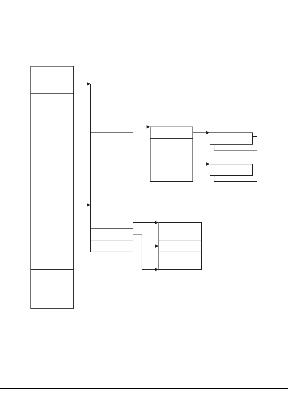
Chapter 5. Problem Determination, Diagnostics, and Recovery 401
1st ed., 6/30/04 - 312579601
Command, Message, Trace Processing
NUCON
CVT
CCVT
MSGEL
CMDPLIST
INTERNAL
TRACE TABLE
CURRENT
TTE
CCVWTOQ
CCVCMDQ
COMANC
MTT
MTTCURR
MTTFIRST
MTTLAST
X’10’:
VECTPTR
TRCTAB
X’A60’:
INTERRUPT
DATA
SAVE
AREA
C29330
Figure 25. Command, Message and Trace Processing

402 VM/HSC 6.0 System Programmer’s Guide
1st ed., 6/30/04 - 312579601
SCP Task/Job Data Relationships
Refer to Figure 26 on page 403 for a description of these relationships.
Subsystem Data Relationships
Refer to Figure 27 on page 404 for a description of these relationships.
Diagnostic Techniques
The user must be logged on the ACS virtual console.
1. Loops:
a. Disabled loops:
1. Press PA1. Enter:
SET RUN OFF
2. Press PA1. Enter:
VMDUMP 0.END FORMAT SLK * comments
The PSW will be within the loop.
b. Enabled loops:
These will be detected by the dispatcher. The logging task will be
‘‘DEFERRED’’ and TTEs for CPU timer interrupts will be produced.
SLUETRAC will indicate the name of the ‘‘DEFERRED’’ task.
When viewing a dump, RQBLOKs which have ‘‘100S’’ in the RQLIC field and
‘‘E’’ in the RQITYPE field, may be looping.
2. Waits:
a. Disabled Waits:
Probably during CMS processing.
1. Press PA1. Enter:
SET RUN OFF
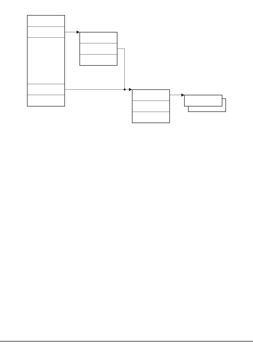
Chapter 5. Problem Determination, Diagnostics, and Recovery 403
1st ed., 6/30/04 - 312579601
NUCON
PSAAOLD
PSATOLD
JBLOK
JBLTASK
TBLOK
TKRBLIST
RQBLOK
C29331
Figure 26. SCP Task/Job Data Relationship
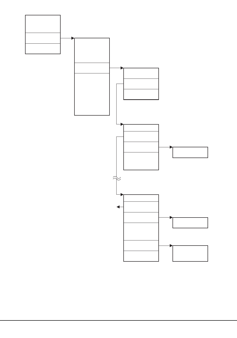
404 VM/HSC 6.0 System Programmer’s Guide
1st ed., 6/30/04 - 312579601
NUCON
VECTPTR CVT
CVTJESCT JESCT
JESSSCT
SSCT
SSCTSCTA
SSCTSSVT
SSCT
SSCTSCTA
SSCTSSVT
SSCTSUSE
SSVT
SSVT
LVT
C29332
Figure 27. Subsystem Data Relationships

Chapter 5. Problem Determination, Diagnostics, and Recovery 405
1st ed., 6/30/04 - 312579601
2. Enter:
D PSW
3. PSW is BC mode if Bit 12 is 0 (high bit in the fourth nibble). If PSW is BC
mode, then enter:
VMDUMP 0.END FORMAT CMS * comments
else enter:
VMDUMP 0.END FORMAT SLK 0 comments
b. Enabled Waits:
These are difficult at best. Whatever failed to happen has already been
obscured. Take a ‘‘FORMAT SLK’’ dump via PA1, or cancel the job that is
hung up with ‘‘DUMP’’. Use the SLUIPCS PRINT command with the
‘‘COMM TASK PTTE IOS’’ options to see what was happening in each
job/task when the system went into the wait. Check the SLUIPCS PRINT
listing for devices with outstanding requests (Count field in DEURQST is not
equal to 0).
Common Dump Analysis Tasks
Here are some common dump analysis tasks and the SLUIPCS SCAN subcommands to
perform them.
Find a Module Plus Offset, Given an Address
WA address
Find a Module Address, Given a Name
WN name
View an HSC or SCP Data Area
VIEW data!area
Identify the Status at ABEND
STAT
Identify the ABEND Code
Look in the PRBxxxxx REPORT file
(or)
STAT

406 VM/HSC 6.0 System Programmer’s Guide
1st ed., 6/30/04 - 312579601
(or)
VIEW NUCON
• If ABEND was the result of an ‘ABEND’ SVC:
- NUCICODE = x’000D’
- NUCIGR1 = ABEND code (system and user)
- NUCIGRF = optional ABEND reason code
• If ABEND was the result of a ‘CALLRTM’:
- NUCICODE = (not) x’000D’
- RTM1FLG1 = has bit x’40’ set
- RTM1SR1 = ABEND code (system and user)
- RTM1SR15 = optional ABEND reason code
Identify the Failing Routine
Look in the ‘PRBxxxxx REPORT’ file
(or)
STAT
WA xx
(xx = address in ‘INSTAD’)
(or)
VIEW NUCON
WA xx
(xx = address in ‘NUCIOPSW’)
Find the Failing Task
VIEW TBLOK PSATOLD
Find the Failing Request Block
VIEW TBLOK PSATOLD
VIEW RQBLOK TKRBLIST
If the third word of TKRBLIST is 00000001 (meaning only 1 RQBLOK on the queue)
then this is the failing request block. Otherwise:
Repeat
Let xx = address in RQPSW
Issue cmd: ‘WA xx’ to find the PSW location
If the module name is ‘SLKRTMxx’ then issue cmd: ‘VIEW RQBLOK RQBQ’ to
get the next one else this is the failing request block until failing request block is
found

Chapter 5. Problem Determination, Diagnostics, and Recovery 407
1st ed., 6/30/04 - 312579601
Save Area Trace Back
Find an R13 value (for example, RQGPR13, NUCIGRD, etc.) TRB address
Find the LVT
VIEW LVT
(or)
Find LVT
(or)
Register 11 usually contains the LVT address for HSC modules (for example, SLS* or
SLU*).
Find the LCT, LST, HST
First, find the LVT (see instructions above)
VIEW LCT LVTLCT
VIEW LST LVTLST
VIEW HST LVTHST
Identify the Last Interrupt Event
TTE R
(or)
VIEW MTT
D xx
(or)
VIEW TTE xx (xx = address in MTTCURR)
Examine the Master Trace Table Header
VIEW MTT
Display Queued WTO Messages
VIEW CCVT
VIEW MSGEL CCVWTOQ
Repeat
VIEW MSGEL MSGQ
until end-of-queue

408 VM/HSC 6.0 System Programmer’s Guide
1st ed., 6/30/04 - 312579601
Examine an SDWA
Find the failing TBLOK (see instructions above)
VIEW RTM2WA TKRTM2WA
Display xx
(xx = address in RT2RSDWA)
Find IUCV Path Descriptors
VIEW CVT
VIEW IRT IRTANC
repeat
VIEW IRT IRTLNK
until end-of-queue
Find IUCV Interrupt Blocks
Find an IRT
VIEW XINT IRTINQ
repeat
VIEW XINT XINTLNK
until end-of-queue
Find IUCV Request Blocks
Find an IRT
VIEW IUB IRTOUTQ
repeat
VIEW IUB IUBQ
until end-of-queue
Gather Diagnostic Materials
During problem resolution, Software Support may request that you provide them with
specific diagnostic material. While printed format may be accepted, it is most desirable
that you provide machine readable data (on magnetic tape). For small amounts of data,
Software Support may request that you FAX the data, instead of mailing it. Sending small
amounts of data by FAX may significantly reduce the time taken to resolve problems.
Diagnostic Materials
HSC diagnostic material may be requested by Software Support and, as appropriate to the
problem, may include one or more of:
• all incidents
- STKACS CONSLOG (requires SET CONSLOG ON)
- HSC level and PUT level
- system software levels

Chapter 5. Problem Determination, Diagnostics, and Recovery 409
1st ed., 6/30/04 - 312579601
- details of problem circumstances
• STKACS abend
- VMDUMP (process with SLUIPCS), CONSLOG, VMFSVLOG (refer to
‘‘Dump Processing’’ on page 5-35)
• problems relating to HSC utilities
- utility SLKJCL
- utility output (SLSPRINT)
- dump data if applicable
- STKACS CONSLOG
• problems relating to CP
- VM operator console log
- STKACS CONSLOG
- EREP or PM2 reports for failing period
- trace data may be required (virtual and real)
- system configuration information
- dump data may be required
• problems relating to PROP message intercept
- PROP console log
- STKACS CONSLOG
- copy of execs and action table
• problems relating to HSC control data set
- copy of CDS
- DASD configuration information (VM directory, ACS SYSPROF, ACS
SLKJCL)
- STKACS CONSLOG (from all hosts if sharing DASD)
- LIBGEN
- CP and SCP trace data (virtual and real)
• problems relating to TMI (TMS interface)
- STKACS CONSLOG
- TMS console log (if VMTAPE, ensure that TMSG is on)
- VM/HSC SCP trace
• problems relating to installation
- console log of virtual machine
- STKACS CONSLOG, VMFSVLOG
- ACS SYSPROF, ACS SYSDEF, ACS SLKJCL
- VM directory entries
- DASD configuration
- additional information as needed.

410 VM/HSC 6.0 System Programmer’s Guide
1st ed., 6/30/04 - 312579601
Tape Format
Software Support prefers that diagnostic data be sent in machine-readable format on tape
in the following format:
• VMFPLC2 format
• for VM dump processing, refer to “Dump Processing” on page 391
• if possible, DO NOT use SPTAPE format.
Tape Return
When requested, Software Support will return any tapes which the sending party has
labeled with a return address.

Chapter 6. Performance Considerations 411
1st ed., 6/30/04 - 312579601
Chapter 6. Performance Considerations
Overview
After installing your Automated Cartridge System you will notice an improvement in your
site system performance, especially for jobs and programs where tape cartridge handling
is involved. Without any tuning, the ACS should significantly decrease mount/dismount
times, shorten batch elapse times, open production windows, and reduce operator
intervention. By making minor performance adjustments, you may achieve even more
efficiency from your library.
The performance of a library is related to the following:
• overall library activity
• actions performed by systems programmers, at installation or during library
operation
• daily operations controlled by an operator.
This chapter contains recommendations and highlights performance techniques that can be
helpful to you in making your library operate more efficiently.
How Library Activity Affects Library Performance
Overall library activity and the type of activities involved are great influences on the
performance of the library. In a large data center, the vast volume of jobs running that
require entering and ejecting of cartridges, mounting, dismounting, tape drive cleaning,
and pass-thru ports determine the performance of the library.
Without proper planning and implementation of techniques to control how all of these
activities affect performance, a library may not operate as intended or preferred.
Therefore, it is important that you customize techniques and employ standard methods
developed especially for your data center to optimize the overall performance of your
library.

412 VM/HSC 6.0 System Programmer’s Guide
1st ed., 6/30/04 - 312579601
How Systems Programmers Control Library Performance
Systems programmers command extensive control of overall library performance. This
control of performance is inherent with how a systems programmer:
• initially configures the library (during the LIBGEN process)
• uses available utilities and commands
• monitors and analyzes performance
• participates in the development of standard methods and procedures for the data
center.
How Operators Control Library Performance
An operator may participate in the initial configuration of a library; however, an operator
usually does not have control to change the majority of the static parameters set for library
operation at installation time. There are exceptions. Some commands relate to the same
functions initially set by PARMLIB control statements. These commands are available for
use by an operator for resetting some library parameters initially set at HSC installation
and initialization.
An operator impacts library performance primarily during daily operations with the use of
operator commands. These commands may be used when operator intervention is required
or when it is necessary to reset some static library parameter to improve performance.
Monitoring Library Activity and Performance
There are several methods to monitor library activity and performance:
• running the Activities Report utility to produce a detailed report identifying
performance values for various library activities.
The data in the report can be easily analyzed to produce performance criteria for your
installation.
• using the StorageTek Performance Measurement and Predictive Maintenance System
(PM2) to collect performance information.
• using Expert Library Manager (ExLM) to monitor performance and to balance
workload. For more information on ExLM, refer to the Expert Library Manager
User Guide and Reference.
Using the Activities Report Utility
The Activities Report utility can be used to effectively record, monitor, and analyze library
performance. Running the utility on a regular basis in addition to comprehensive analyses
can provide you with information disclosing total performance characteristics for your
library.
The Activities Report utility generates a report listing relative activity by volume groups.
Information reflected on this report can be used to redistribute resources and, if necessary,
to balance the cartridge activity load in a library.

Chapter 6. Performance Considerations 413
1st ed., 6/30/04 - 312579601
This utility provides the library administrator with the information necessary to balance
mount/dismount activity across ACSs and LSMs within a library. The information is
based on statistics contained in SMF records that are tallied for each cartridge movement.
Total Mount and Dismount activity is categorized to show a percentage for:
• scratch mount/total mounts and average time per mount
• nonscratch mounts/total mounts, and average time per mount
• scratch mounts in a different LSM/total mounts, average time per mount, and
average number of pass-thrus
• nonscratch mounts in a different LSM/total mounts, average time per mount, and
average number of cartridge exchanges.
Refer to Chapter 4, “Utility Functions” on page 169 for detailed information on the
Activities Report utility.
Using the Performance Measurement and Predictive Maintenance System (PM2)
The Performance Measurement and Predictive Maintenance System generates
performance and error reports on various StorageTek equipment, including the library.
There are two categories of reports that provide information about library operation:
• ACS Daily Report
• Tape Volume Report.
ACS Daily Report
The ACS Daily Report contains the following information:
• Library Subsystem Error Report
• LMU Response Summary
• Problem Volume Serial List
• ACS Deblocking Error Report
• ACS Door Open Summary
• ACS LMU Degraded Summary
• ACS Database Journaling Entry
• ACS Primary/Shadow Switch Record
• ACS Audit Required Summary
• ACS Host Recovery Summary.
Tape Volume Report
The Tape Volume Report contains the following information:
• Tape Volume Select
• Tape Volume Analysis.
Refer to the PM2 Report Description & Analysis Manual - Install User’s Manual for
detailed information about PM2 and the reports that can be helpful to you in monitoring
library performance.

414 VM/HSC 6.0 System Programmer’s Guide
1st ed., 6/30/04 - 312579601
Redistribute Scratch Volumes in the Library
The Scratch Redistribution utility allows you to redistribute scratch volumes across the
LSMs within a particular ACS. You can choose to have the scratch volumes go to only
specified LSMs or all LSMs within an ACS.
Redistribution is performed to an evenness defined by the balance tolerance level which is
specified via the Scratch Redistribution utility. If necessary, the Scratch Redistribution
utility swaps scratch volumes with nonscratch volumes to equalize the count of scratch
cartridges in an ACS.
Refer to Chapter 4, “Utility Functions” on page 169 for detailed information on the
Scratch Redistribution utility, syntax, and parameters.
Maintain Quantities of Scratch Cartridges
Typically, in a high-activity environment, if there are insufficient quantities of scratch
volumes available within a library, production time can be lost. Scratch volumes are
maintained in scratch pools that are defined across the library LSMs. It is important that
the number of cartridges maintained in the scratch pools are sufficient enough for normal
library operation at your data center. The operator or the systems programmer can control
when the HSC warns of low quantities of scratch cartridges.
The Warn command establishes thresholds which control when the HSC notifies the
operator of an insufficient quantity of scratch cartridges in an ACS. The scratch pool
depletion warning notifies the operator when the number of scratch volumes in an ACS
falls below a specified minimum value.
By specifying warning thresholds, you can know when the number of scratch cartridges is
too low for normal library operation.
Refer to the HSC Operator’s Guide for more information about the command, syntax, and
parameters.
Define CAP Preferences
The physical configuration of your library, especially the location of CAPs, can affect both
library performance and operator performance. For a more efficient operation, ideally the
operator should be located close to the CAPs being used the most. You can control which
CAPs are most used.
The CAP preference (CAPPref) command enables you to specify preference values for
CAPs. If CAP preferences are not specified, the CAP preference value is set to zero. A
CAP with a preference value of zero is never selected (defaulted to) by the HSC unless
specifically requested. The CAP preference list specified in the command establishes an
ordered list of CAPs for use during cartridge entry and ejection. The HSC chooses an
available CAP from this list by starting at the highest priority and moving down the list
until a nonbusy, nonzero-priority CAP is identified.

Chapter 6. Performance Considerations 415
1st ed., 6/30/04 - 312579601
If ejects and/or enters of large numbers of cartridges are frequent, you may want to set
higher CAP preferences for enhanced CAPs.
Refer to the HSC Operator’s Guide for information about the CAPPref command.
Use SMF Records to Collect Performance Data
Library performance data can be accumulated from SMF records. The SMF operand of the
SLILIBRY macro for LIBGEN or the SMF parameter of the HSC SET utility determines
the SMF record type written by the HSC. The SCP SET PERFLOG command is used to
enable or disable recording of SMF data and to close the data file (and reopen if enabled).
The command also allows specifying which SMF record subtypes are to be collected.
Refer to the HSC Operator’s Guide for additional details.
With SMF recording enabled, a record of various library activities is made for the
specified record subtypes. Each library activity, such as each time the VIew command
(optional subtype(8)) is used, each time a cartridge is entered or ejected, etc., is recorded
as an SMF subtype record.
The performance log data file that is created can be used to analyze library performance.
Software analytical tools can be used to manipulate the data and create various
performance statistics.
Refer to Appendix C, “Record Formats” on page 497 for detailed information about SMF
record subtypes. Refer to “SET Utility” on page 299 for information about the SET utility,
syntax, and parameters.
Use PARMLIB to Define Static Parameters
PARMLIB control statements can be specified to the HSC startup SLKJCL file. At HSC
installation, the various performance criteria specified by the control statements are
statically established. The systems programmer may specify these control statements to be
executed when the HSC software is initialized. Most of the statically set parameters can be
changed at any time after initialization by issuing an appropriate operator command.
Table 28 summarizes the PARMLIB control statements with corresponding operator
commands. Any of the PARMLIB control statements can be used to improve various
performance aspects of library operation.
Table 28. Performance Parameters Controlled by PARMLIB Control Statements
Performance Parameter Control Statement Operator Command
CAP Preference CAPPref CAPPref
Control Data Set Definition CDSDEF
Host-to-Host Communications Path COMMPath COMMPath
Control Message Prefix, Eid, Fid, and
Hostid
EXECPARM

416 VM/HSC 6.0 System Programmer’s Guide
1st ed., 6/30/04 - 312579601
Refer to “PARMLIB Control Statements” on page 83 for detailed information about using
PARMLIB control statements.
Journal Definition JRNDEF Journal (specify
FULL=Abend or
FULL=Continue)
Journals JRNDEF Journal (specify
FULL=Abend or
FULL=Continue)
Mount Processing MNTD MNTD
General Purpose Options OPTion OPTion
Scratch Subpool SCRPool Warn (specify SUBpool
option)
Table 28. Performance Parameters Controlled by PARMLIB Control Statements
Performance Parameter Control Statement Operator Command

Chapter 6. Performance Considerations 417
1st ed., 6/30/04 - 312579601
Define High Dispatching Priority for the HSC
The VM dispatch priority and SHARE settings of the ACS service machine may be altered
to improve overall HSC performance for a VM host system.
Set High-Performance Host-to-Host Communications
In a multi-host ACS configuration, host-to-host communications allows hosts to notify
each other of a CDS switch. Host-to-host communications can be accommodated through
three performance levels of communications, ranked as follows:
•ACF/VTAM
•the LMU(s)
•the CDS.
The high-performance telecommunications method is through VTAM. This method is
recommended by StorageTek. Host-to-host communications through the control data set
should be used only as a backup facility. You should implement the highest level of
host-to-host communications available.
‘‘Communication Functions’’ and ‘‘Communications Path (COMMPath) Command and
Control Statement’’ in the HSC Operator’s Guide describe how multiple hosts are
connected by any of the three possible communication methods. You have the capability
to set or dynamically switch the host-to-host communication method between each pair of
hosts. You can monitor the level of communication using the Display COMMPath
command. If a level of communications fails, it automatically drops to the next lower
level, allowing the HSC to continue without interruption.
The communications parameters can be modified dynamically, using the COMMPath
command, without halting HSC execution.
Detailed Information about Host-to-Host Communications
Refer to “Communication Functions” on page 78 and to ‘‘Communications Path
(COMMPath) Command and Control Statement’’ in the HSC Operator’s Guide for a
general description of communication functions.
Refer to “PARMLIB Control Statements” on page 83 for how to define communication
functions in a PARMLIB control statement.
The HSC Operator’s Guide contains information about the operator commands for
controlling the host-to-host communication path.

418 VM/HSC 6.0 System Programmer’s Guide
1st ed., 6/30/04 - 312579601
Functioning of Host-to-Host Communications
The method hierarchy that is established is, from highest to lowest, VTAM, LMU, CDS.
Initially, all methods are set to CDS. Appropriate entries can be placed in the PARMLIB
statement to set the communications method at HSC initialization. If an error in
communications occurs during communications with the current communication method,
a method switch is performed.
The system may switch from a method of VTAM to LMU, selecting the first LMU
available from a list of defined LMUs. If the current method is LMU, the system attempts
to find the next LMU available from the list, or switches from LMU to CDS. If a list of
LMUs has not been defined by the PARMLIB statement, or if no LMUs are available, the
system switches directly from VTAM to CDS.
Note: After a downward switch has occurred, you must issue an operator command to
perform an upward switch (for example, from CDS to LMU, CDS to VTAM, or LMU to
VTAM).
Figure 8 on page 79 illustrates how various combinations of communication methods can
exist at the same time between multiple hosts.
Designation of Communication parameters
When specifying communication parameters in the operator command, the parameters can
designate different actions depending upon whether or not the host specified in the
command is the host that is executing the command.
When the command is defining parameters for the host executing the command, the
method parameter defines the highest method in the hierarchy allowed to be defined on
that host.
If a command defining parameters for another host specifies a higher method, the current
method for this other host is set to the executing host’s limit, if possible. To change a
host’s method hierarchy limit, the command must be issued on that host, except during
HSC initialization when the method is set from a PARMLIB control statement.
When the command is defining parameters for the host executing the command, the
LMUpath parameter defines those LMUs this host is allowed to use for sending messages.
For two hosts to communicate via an LMU, there must be matching entries in their
respective LMUpath lists.
Careful analysis should be performed when defining the communication method in the
PARMLIB control statement because of how the system handles the switching.

Chapter 6. Performance Considerations 419
1st ed., 6/30/04 - 312579601
Define Secondary and Standby Control Data Sets
Various controls and services are in place in the HSC subsystem to ensure that the primary
control data set maintains its integrity. Included among the controls are the capability to:
• designate secondary and standby control data sets as backup
• run BACKup and RESTore utilities
• designate journal data sets for use in recovery of control data set errors.
However, though all of these means are available, you must configure your installation to
take advantage of the capabilities. At installation, when defining the library configuration,
it is important that you initialize the additional control data sets.
It is highly recommended that secondary and standby data sets be used to ensure the
performance and reliability of your library.
Refer to Chapter 7, ‘‘Allocating and Initializing Control Data Sets’’ in the HSC
Installation Guide for information about defining control data set requirements at HSC
installation.
The HSC Operator’s Guide contains information about the operator commands to control
switching of control data sets.
Limit View Time to Maintain High Performance
Certain conditions within a library can significantly affect performance. These conditions
may occur because of software issues or simply because of daily procedures used within a
data center. The VIew command is invoked to improve performance because it can be
used to quickly resolve problems. It can often eliminate the need for an operator to open
an LSM door and enter the LSM to resolve a problem. Excessive use of the VIew
command is a typical example of how library performance can be drastically affected
unless you plan and consider how it can impact the performance of your library.
Note: The SL8500 library does not contain a camera, so the VIew command is not
useful in that environment.
Though the VIew command is primarily used by operators, it is important for systems
programmers to know that excessive use of the VIew command for extended periods of
time can impact the performance of an LSM and your library. However, you should use
the VIew command to inspect the interior of an LSM rather than place the LSM in manual
mode and physically enter the LSM. If it is necessary to inspect the robot, its hands, and/or
cameras, you must modify the LSM offline and enter through the access door.
Default view time can be controlled with the OPTion command’s Viewtime parameter.
The system default for view time is 10 seconds. However, you can change this default
value to fit your needs.
Refer to ‘‘Option Command and Control Statement’’ in Appendix A, ‘‘Macros, Control
Statements, Utilities, and Commands Syntax Reference’’ or to Chapter 2 in the HSC
Operator’s Guide for detailed information about the OPTion command’s syntax and
parameters.

420 VM/HSC 6.0 System Programmer’s Guide
1st ed., 6/30/04 - 312579601
Excessive Use of VIew Command Affects Performance
Each time the VIew command is invoked, the automatic functioning occurring within an
LSM is interrupted. During the interruption, the robot hands and associated cameras are
stopped from performing HSC directed library functions to focus on some specified area
within the LSM for some specified time interval. Any manual intervention with library
functioning can have a negative effect on the throughput of an LSM and consequently
affect overall library performance.
How to Monitor Usage of the VIew Command
There are two facilities available for monitoring use of the VIew command:
• enabling SMF logging
• running and analyzing the Activities Report.
It is highly recommended that you enable recording of the subtype 8 SMF record. After
each successful use of the VIew command, a subtype 8 SMF record is written. The record
documents the component that was viewed, the view time requested, and the actual view
time used. Be aware that the time actually used can be shorter than time requested at the
invocation of the command, if the operator responds to the outstanding WTOR before the
expiration of the requested time interval. Refer to ‘‘Adding SMF Parameters’’ in the HSC
Installation Guide for details on how to specify the SMF parameters.
Note: Subtype 8 SMF record logging is not a default and must be specified in accordance
with the instructions contained in the referenced paragraph.
Another useful technique to monitor the use of the VIew command is to run the Activities
Report utility and to thoroughly analyze the resulting report. Heavy use of the VIew
command results in low levels for performance criteria delineated in an Activity Report.
Depending upon system load for the specified time reported in an Activity Report, most
performance parameters are adversely affected by excessive use of the command. For
example, LSM ARM USE percentages reflected in an Activities Report are most likely to
be low during heavy use of the command.
Each successful use of the VIew command is counted as one robotic motion for reliability
measuring (R+) purposes. Refer to Appendix D, “Logging ACS Robotics Motion” on
page 603 for information on robotic statistics logging.
Advantages of Using the VIew Command
There are definite advantages for using the VIew command as opposed to other
alternatives. Obvious benefits for using the command include:
• The VIew command easily permits monitoring of tape drives and other LSM
components with the execution of a single command entered at the system console.
The LSM does not need to be modified offline to execute the command.
• The operator does not enter the LSM.
• The camera can be focused on a specific component that is considered as suspect;
thus, time is saved by avoiding the lengthy process of physically entering the LSM.

Chapter 6. Performance Considerations 421
1st ed., 6/30/04 - 312579601
• With the use of SMF logging, accurate records can be accumulated for system
analysis or to monitor system status.

422 VM/HSC 6.0 System Programmer’s Guide
1st ed., 6/30/04 - 312579601
Loading Cartridges Into the Library
There are different methods that can be used to load an LSM with cartridges at installation
time. There are advantages and disadvantages involved for each method. The following
brief discussions may help you determine which loading method is best for your
installation.
Loading Cartridges for Immediate Use in a Newly Installed LSM
If you are loading cartridges into an LSM that must be placed into production, it may be
advantageous to begin entering volumes a few at a time through the CAP.
Tape cartridges can be entered into an LSM by using the ENter command or ENTEr utility
to enter cartridges through the CAP.
Refer to “Enter Cartridges Utility” on page 249 for information about the ENTEr
Cartridges utility, the syntax, and parameters. Refer to the ‘‘CAP Preference (CAPPref)
Command and Control Statement’’ in the HSC Operator’s Guide for information about
how to set the CAP in automatic mode. Refer to the HSC Operator’s Guide for
information about the ENter command.
The control data set is updated with each load of cartridges entered through the CAP.
If you begin entering cartridges containing data sets known to be required by regularly
scheduled jobs, these volumes are immediately available for use. The obvious advantage
of using this method is that the LSM and any cartridges entered are immediately available
for use.
Loading Cartridges for Later Use in a Newly Installed LSM
If you are loading cartridges into an LSM that is not scheduled for production
immediately, it may be to your advantage to manually load the entire LSM. The cartridges
must be previously initialized to use this method.
After all cartridges are loaded into cells, run the AUDIt utility for the LSM to update the
control data set.
This method of loading cartridges into an LSM is faster for physically moving the
cartridges and takes less operator time. However, running the AUDIt utility for an entire
LSM can take a significant amount of time.
Reduce Pass-Thrus
The number of pass-thrus required to mount, dismount, and replace cartridges in LSMs
can impact library performance. In a large or busy ACS, this impact may be significant
especially during periods of heavy mount activity. There are three categories of pass-thrus:
• unavoidable
• unnecessary
• scheduled.

Chapter 6. Performance Considerations 423
1st ed., 6/30/04 - 312579601
Unavoidable Pass-Thrus
The HSC attempts to minimize the number of pass-thrus required; however, depending
upon available tape transports and locations of cartridges, pass-thrus often cannot be
avoided. By running Activities Reports on a regular basis and examining the results, you
can see that mounts for different LSMs take longer than mounts for the same LSM.
Unnecessary Pass-Thrus
Scratch mounts, dismounts, enters, and ejects that require pass-thrus are unnecessary and
should be avoided. These types of activities divert the robot from productive work
especially during periods of peak activity.
If scratch subpools are properly defined and managed, scratch cartridges normally are not
involved in pass-thrus. Scratch mounts are the same as specific mounts as far as pass-thrus
that cannot be avoided. In general, you should never see a scratch pass-thru. But, if you do
see a scratch pass-thru, it was unavoidable.
The effect of unnecessary pass-thrus is not obvious in the Activities Report. You must
compare their number with average mount times to see the effect on performance.
Scheduled Pass-Thrus
Using the Scratch Redistribution utility to balance scratch cartridges involves moving
cartridges to various LSMs to achieve scratch balancing. This type of activity involves
heavy pass-thru usage. If you must balance scratch volumes across your library, schedule
such activity during off peak hours. This approach will ensure that the pass-thru activity
involved does not directly interfere with mounts and dismounts for high-priority
production.
You can use Expert Library Manager (ExLM) to schedule pass-thrus. Refer to the Expert
Library Manager User and Reference Guide for more information.
Ways to Reduce Pass-Thru Activity
There are various ways to reduce pass-thru activity. Each of these ways is briefly
discussed in the following paragraphs.
Set MNTD Float to ON
The Float option of the MNTD command specifies whether the HSC is to select a
new home cell location when it dismounts a volume that requires a pass-thru when it
is dismounted.
When MNTD Float is set to ON, cartridges are not passed back to their original
LSM. The cartridges are assigned new cells in the LSM where they are dismounted.
This action eliminates most unnecessary pass-thrus.
Set MNTD SCRDISM to CURRENT
When MNTD SCRDISM is set to CURRENT, scratch cartridges mounted in a 9360
(WolfCreek) LSM are dismounted in the same device rather than being archived in
the next largest storage device.

424 VM/HSC 6.0 System Programmer’s Guide
1st ed., 6/30/04 - 312579601
Ensure adequate free cells
Setting MNTD Float to ON can be defeated if there are no free cells in the
dismounting LSM. Dismounted cartridges are passed to other LSMs to find a new
home cell.
Use the Display Lsm command to determine the number of free cells in each LSM.
Use MOVe or EJect to create free cells if they are needed.
Eject through the CAP closest to the cartridge
If you eject a cartridge through the CAP of the LSM where it resides, no pass-thrus
are required.
If you eject a cartridge without specifying a CAPid, the cartridge is ejected through
the highest priority CAP that is not busy. This type of activity may cause one or more
unnecessary, nonproductive pass-thrus.
The recommended way to accomplish ejects without affecting performance with
pass-thrus, is to use multiple CAP option on the EJECt utility. By specifying multiple
CAPs (that is, CAP(000,001,002)), the desired effect (that is, no pass-thrus) is
achieved.
Redistribute cartridges during off-peak times
You can use the MOVe command and utility to move cartridges within an LSM or
between LSMs. The Scratch Redistribution utility can be used to move scratch
cartridges between LSMs until an equilibrium is reached. Each inter-LSM movement
of cartridges causes pass-thrus which delay robot movement in mounting a cartridge.
Depending on the number of cartridges to be redistributed, you may prefer to
schedule moves and scratch redistribution during periods of low data center activity.
The redistribution runs faster and performance is not affected during off peak times.
Reduce Operator Intervention
Although the ACS runs mostly unattended, situations occur where operator intervention is
required. Excessive and unnecessary operator intervention impacts library performance.
There are specific ways in which operator intervention can be reduced. These include:
Set CAP Preference
In a multiple-LSM ACS, the CAPPref command establishes an ordered list of CAPs
to use should the operator or HSC start an activity that requires a CAP without
specifying a CAPid.
To motivate operators to enter or eject cartridges faster, set CAPPref such that the
CAP closest to the cartridge racks is preferred. This minimizes operator travel
distance.
In large ACS configurations, of five or more LSMs, consider setting CAPPref such
that a CAP in the middle of the ACS has the highest priority. This may make the
operators walk further, but it reduces the number of pass-thrus should the default
(highest priority) CAPid be used for ejecting cartridges.

Chapter 6. Performance Considerations 425
1st ed., 6/30/04 - 312579601
Prefetch Enters
Nonlibrary cartridges that are mounted on library transports are delayed while the
operator fetches and enters them. This is a common occurrence for HSC sites with all
transports attached to the library.
If you or your scheduling system can predict which nonlibrary cartridges will be
mounted in the library before a mount message appears, your operator can improve
performance by entering those cartridges in advance.
Avoid Crashing Test Systems
Library attached hosts own library resources, including CAPs, tape drives, and
cartridges. If a host fails, another host must clean up the resources held by the failing
host. This delays mounts and dismounts on the recovering host while recovery takes
place.
You should attempt to shut down the HSC properly before IPLing a system. This is
especially important for test systems that may be restarted several times a day.
Reduce Tape Transport Contention
Balanced use of library tape transports results in better robotic and system
performance. In a multiple LSM library, you want the workload to be spread evenly
among the robots rather than having one robot overloaded while the others are idle.
Within each LSM, you want mounts to be evenly distributed among transports rather
than having the robot wait for a cartridge to be rewound so it can mount the next
cartridge on the same tape transport.
Tape transport contention can be reduced by:
• ensuring scratch cartridge balance
• managing multi-host tape transports
• avoiding dedicating tape transports
ACSPROP EXEC
Utility ACSPROP EXEC is provided for use as a programmable operator (PROP) action
routine to process all
TAPE raddr DETACHED...
messages which CP sends to the system console.
It issues library DISMount commands for the given tape drive (raddr). The dismount is
honored if the HSC did a mount to that device for the same host. VM (CP) causes a
‘Rewind Unload’ command to be executed on any tape drive DETACHed by the CP
commands LOGOFF, FORCE, or DETACH. This would leave a library volume in a
‘selected’ state physically sitting in a library transport. The volume is unavailable to any
requestor until it is removed from the drive and placed back in a storage cell of an LSM.
ACSPROP EXEC is an ‘‘action routine’’ which may be invoked by the VM
PRogrammable OPerator service to issue HSC DISMount commands when a tape drive is

426 VM/HSC 6.0 System Programmer’s Guide
1st ed., 6/30/04 - 312579601
DETACHed from a virtual machine. This enables the volume to be available (that is,
unselected) earlier than would otherwise be possible.
ACSPROP EXEC can also be used with VMOPERATOR to trap MOUNT messages for
VMTAPE. LOGTABLE SAMPLE contains sample VMOPERATOR LOGTABLE
statements to assist you. Consult VMOPERATOR documentation for information about
tailoring the samples to your needs.
Syntax
Parameters
There are no external parameters required. The PROP interface to an EXEC action routine
provides parameters in the program stack. These are documented in the VM description of
PROP.
Usage Requirements
The only requirement is that the PROP ‘logical operator’ have a link to the MAINTSTK
RUN-disk.
Reduce Scheduling Contention
Effective scheduling can increase library performance. Controlling the following
scheduling related areas can help significantly in further increasing library performance:
• strive for a balanced workload
• schedule nonproductive library activities during low-demand times.
Balancing the Workload
If you experience higher than expected average mount times, but at the same time
experience an improvement in production through-put, it could be an indication that
your system is periodically flooded with work rather than having a balanced
workload.
For example, all of your production jobs may be getting submitted at the beginning
of a shift so that the library robots are overworked for the first few hours of the shift.
Then, the robots may remain idle for the remainder of the shift. If you are using a
scheduling software package and it releases jobs every hour on the hour, there may
be tremendous tape transport contention for the first few minutes of each hour while
the transports are unused for the remainder of each hour.
These situations tend to elevate average mount times; however, as long as the work is
performed on time, there is probably no need to change conditions. However, if the
work is not getting performed on schedule, you can improve performance by
balancing your production workload.
EXEC
ACSPROP

Chapter 6. Performance Considerations 427
1st ed., 6/30/04 - 312579601
Scheduling Nonproductive Activities During Low-Demand Times
There are several library utilities, which, though very essential, severely impact the
library’s ability to mount and dismount cartridges. The following utilities should not
be run when high-priority production jobs are pending:
• AUDIt
•EJECt
• Enter Cartridges
•MOVe
• Scratch Redistribution
• Scratch Update.
These utilities should be scheduled during quiet periods so they do not contend with
mounts and dismounts. Running these activities during quiet periods also ensures
that the tasks complete faster. In the case of mass enters or ejects, operator’s time can
also be optimized.
Use Performance Log Reblocker to Format Data
The performance log reblocker (SLUPERF) prepares the performance log file produced
by the SCP for use by the library Activities Report utility. The utility executes in both
MVS and VM environments, for which different versions of the utility are produced.
In the VM environment, SLUPERF reads an SCP performance log spool file into a CMS
file, preserving the internal record format. There should be no header or trailer data in the
file.
Additional information on this utility can be found in “Performance Log Reblocker
Utility” on page 263.
Use the Audit Utility Effectively
The AUDIt utility causes the robot to read cartridge labels. Tape cartridge information is
uploaded to the CDS. In a quiesced LSM, performing an audit on a full panel can take up
to 15 minutes, depending upon the LSM type, size, and configuration.
You should keep in mind that empty cells slow down an audit. If the robot cannot read a
cartridge label, it must reach out to determine if the cell is empty. Each empty cell takes
approximately three times longer to audit than a cell containing a cartridge.
If you are partially filling an LSM before running an audit, you should fill as many
complete panels as possible and then audit only those filled panels. Avoid auditing empty
cells.
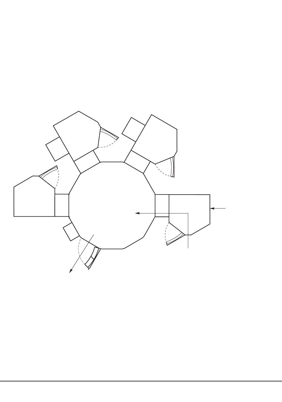
428 VM/HSC 6.0 System Programmer’s Guide
1st ed., 6/30/04 - 312579601
Use LSMs as Scratch Loaders in a Mixed ACS
In an environment where massive cartridge input is required or a lot of cartridge
movement occurs, 9360 (WolfCreek) or 9310 (PowderHorn) LSMs can be used to
simulate scratch loaders intermixed with 4410 LSMs to improve library performance.
1. Specify the following operator command:
MNTD SCRDISM(ARCHIVE)
2. Run scratch redistribution frequently.
3. Eject cartridges when necessary from the archive device (4410 or 9310).
Figure 28 shows a 9360 used as a scratch loader.
4410 9360 1) Enter scratches
into 9360
2) Archive scratches
from 9360 to 4410
3) Eject cartridges from
the archive device (4410)
through the enhanced CAP
9360
9360
9360
LCU
C46014
Figure 28. Using LSMs as Scratch Loaders

Appendix A. Macros, Control Statements, Utilities, and Commands Syntax Reference 429
1st ed., 6/30/04 - 312579601
Appendix A. Macros, Control Statements, Utilities, and
Commands Syntax Reference
Syntax Flow Diagrams
Syntax is illustrated using flow diagrams. These can include the following elements:
• syntax – the diagram itself.
• items – individual elements inside the diagram. Items can be keywords, variables,
delimiters, operators, fragment references, and separators.
• groups – a collection of items or other groups.
The following sections describe syntax flow diagram features and include some generic
examples.
Specifying Commands
Commands are composed of command names, keyword parameters, and positional
parameters. Command names initiate command execution, keyword parameters are
operands that contain keywords and their related values, and positional parameters are
operands that are identified by their position in the command string rather than by
keywords.
• Keyword parameters can be specified in any order. The HSC accepts (tolerates)
multiple occurrences of a keyword. The value assigned to a keyword reflects the last
occurrence of a keyword within a command.
• Positional parameters must be entered in the order shown in the syntax diagram.
• Uppercase letters indicate the minimum abbreviation for the command name,
keyword, or positional parameter.
Variables
Variables are italicized.
Delimiters
If a comma (,), a semicolon (;), or other delimiter is shown with an element of the syntax
diagram, it must be entered as part of the statement or command.
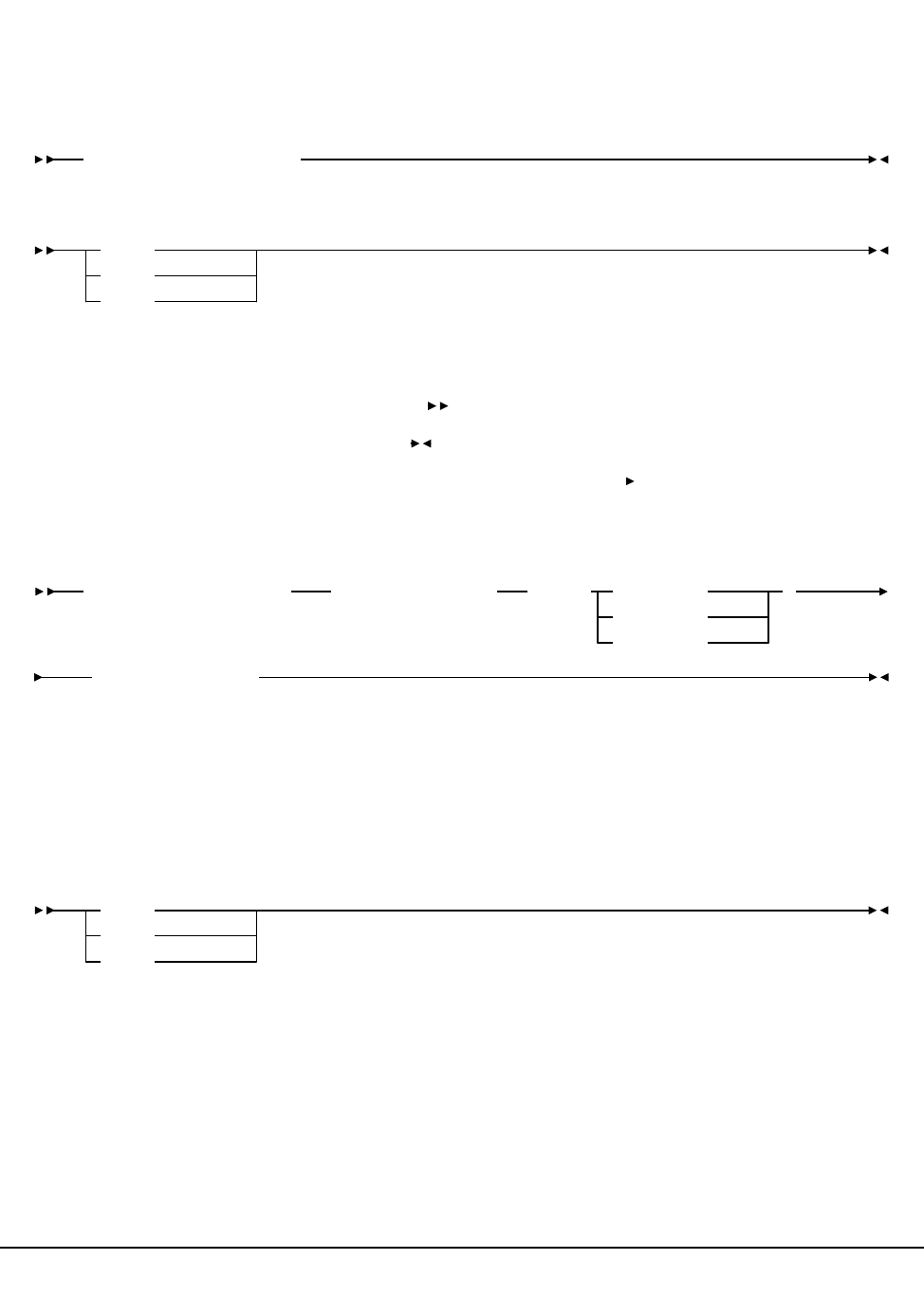
430 VM/HSC 6.0 System Programmer’s Guide
1st ed., 6/30/04 - 312579601
Flow Lines
Syntax diagrams consist of horizontal and vertical lines and the text of a command,
control statement, macro, or utility.
or
Diagrams are read left to right and top to bottom. Arrows indicate flow and direction.
• a statement begins with
• a statement ends with
• diagrams continuing to the next line begin with
• fragments begin and end with |
Single Required Choice
Branch lines, without repeat arrows, indicate that a single choice must be made. If one of
the items from which a choice is being made is on the base line of the diagram, a single
choice is required.
COMMAND/MACRO/UTILITY
Item1
Item2
Item3
COMMAND/UTILITY NAME
Item3(variable5)
Item1(variable1)Item2( variable2
variable3
variable4
)
Item1
Item2
Item3
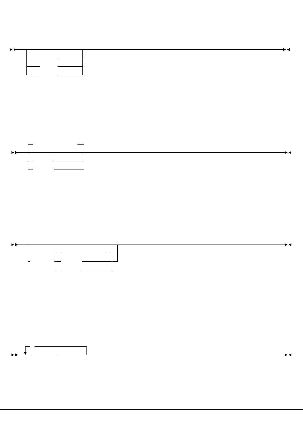
Appendix A. Macros, Control Statements, Utilities, and Commands Syntax Reference 431
1st ed., 6/30/04 - 312579601
Single Optional Choice
If the first item is on the line below the base line, a single choice of items in the stack is
optional.
Defaults
Default values and parameters appear above the syntax diagram line. In the following
example, if a value is not specified with the command, Default Value is used by the HSC.
Some keyword parameters provide a choice of values in a stack. When the stack contains a
default value, the keyword and the value choices are placed below the baseline to indicate
that they are optional, and the default value appears above the keyword line. In the
following example, if the keyword is not specified with the command, Keyword(Default
Value) is used by the HSC.
Repeat Symbol
A repeat symbol indicates that more than one choice can be made or that a single choice
can be made more than once. The repeat symbol shown in this example indicates that a
comma is required as the repeat separator.
Item3
Item1
Item2
Value2
Value3
Default Value
Keyword
Value3
Default Value
Value2
,
variable

432 VM/HSC 6.0 System Programmer’s Guide
1st ed., 6/30/04 - 312579601
Syntax Continuation (Fragments)
Fragment references direct you to parts (fragments) of the syntax that contain more detail
than can be shown in the main syntax diagram.
COMMAND/UTILITY NAME Fragment Reference
Item1(
Fragment:
variable2
,variable1
variable4
variable3 )
Item2(
variable6
,variable5
variable8
variable7 )

Appendix A. Macros, Control Statements, Utilities, and Commands Syntax Reference 433
1st ed., 6/30/04 - 312579601
Library Identification
Each ACS, LSM, and CAP is assigned a unique identification number during LIBGEN.
Use this number in HSC commands and utilities when identifying a specific ACSid,
LSMid, or CAPid.
•ACSid (acs-id) is a hexadecimal value from 00 through FF that identifies the LMU.
An acs-id is the result of defining the SLIALIST macro during a LIBGEN. See
‘‘LIBGEN Macros’’ in the HSC Configuration Guide for information about the
SLIALIST macro. The first ACS listed in this macro acquires a hexadecimal
identifier of 00, the second ACS listed acquires a hexadecimal identifier of 01, and so
forth until all ACSs are identified.
• An LSM number (ll) is a hexadecimal value from 00 through 17. It differentiates an
LSM from every other LSM connected to the same LMU.
An LSM number is the result of defining the SLIACS macro LSM parameter. See the
HSC Configuration Guide for information about the SLIACS macro. The first LSM
listed for an ACS acquires a hexadecimal number of 00, the second LSM listed for an
ACS acquires a hexadecimal number of 01, and so forth.
• An LSMid (lsm-id) is made up of the ACSid and the LSM number separated by a
colon (:). It differentiates an LSM from every other LSM in a library.
• A CAP number is a hexadecimal value from 00 to 02. The CAP number identifies a
specific CAP in an LSM that has more than one CAP.
•A CAPid (cap-id) is a hexadecimal value made up of the LSMid and the CAP
number separated by a colon. Refer to “How to Specify a CAPid” on page 434 for
more information.
Some HSC commands and utilities require, or optionally allow, the user to specify a host
identifier or a VOLSER.
•The host-id for a given host is the identifier specified in the HOSTID parameter of
the SLILIBRY macro in the LIBGEN. Valid characters for a HOSTID are A-Z, 0-9,
#, $, and @.
• A VOLSER (volser) identifies a volume serial number consisting of one to six
characters. Valid characters are A-Z, 0-9, # (crosshatch), $, ¥ (yen character), and
optional trailing blanks. Leading blanks are not allowed.

434 VM/HSC 6.0 System Programmer’s Guide
1st ed., 6/30/04 - 312579601
How to Specify a CAPid
A CAPid specifies a particular CAP in the library. Each CAP is identified by the LSMid of
the LSM that the CAP is attached to and a CAP number to distinguish it from other CAPs
in that LSM.
CAP configurations differ based on the LSM type. The following configurations are
possible:
LSM (Model 4410) and PowderHorn LSM (Model 9310)
This LSM is configured with either the standard 21-cell CAP or an enhanced CAP.
An enhanced CAP contains two 40-cell magazine-style CAPs and a one-cell priority
CAP (PCAP). The 40-cell CAPs function independently.
WolfCreek LSM (Models 9360-050, 9360-075, and 9360-100)
This LSM is configured with a WolfCreek CAP which contains a 20-cell
magazine-style CAP and a PCAP. An optional 30-cell, magazine-style CAP, called a
WolfCreek optional CAP, may be added to the WolfCreek CAP.
TimberWolf LSM (Model 9740)
This LSM is configured with either a 14-cell permanent rack or a 10-cell removable
magazine.
StreamLine Library (Model 8500)
This library is configured with 3, 13-cell removable magazines. An optional 39-cell
CAP can be added.
CAPid Formats
There are two formats that can be used to specify a CAPid:
•AA:LL, where AA is the ACSid and LL is the LSM number. This format is referred to
as the lsm-id.
•AA:LL:CC, where AA:LL is the LSMid and CC is the CAP number. This format is
referred to as the cap-id.
Caution:
Do not use a colon as the MVS command delimiter because the system will process
the colon in the new CAPid format as the end of the command. All information
following the colon in an HSC command will not be processed.
The appropriate format to use is determined by the CAP hardware and the command being
specified.
•The AA:LL format can be specified in the following situations:
- to specify a standard CAP
- to allow the HSC to select a CAP based on CAP preference.

Appendix A. Macros, Control Statements, Utilities, and Commands Syntax Reference 435
1st ed., 6/30/04 - 312579601
•The AA:LL:CC format can be specified for any CAP hardware in any command that
accepts a CAPid. This is the preferred format. Valid CAP numbers are:
00 indicates one of the following:
- a 21-cell standard CAP
- the right-hand 40-cell CAP of an enhanced CAP
- the 20-cell CAP of a WolfCreek CAP
- a 14-cell or 10-cell removable magazine 9740 TimberWolf CAP
- the 3, 13-cell removable magazines for an SL8500 CAP.
01 indicates one of the following:
- the left-hand 40-cell CAP of an enhanced CAP
- the 30-cell CAP of a WolfCreek optional CAP
- the 3, 13-cell removable magazines for an optional SL8500 CAP.
02 indicates the PCAP in either an enhanced CAP or a WolfCreek CAP.
Note: Refer to the individual command explanations for additional information on
specifying CAPids.

436 VM/HSC 6.0 System Programmer’s Guide
1st ed., 6/30/04 - 312579601
Ranges And Lists
HSC commands and utilities often allow the user to specify ranges and lists of elements.
1. An inclusive range is indicated by a pair of elements of the same length and data
type, joined by a dash. The first element must be strictly less than the second
element.
• A hexadecimal range consists of a pair of hexadecimal numbers (for example,
0A2-0AD, or 000-0FC).
• A decimal range consists of a pair of decimal numbers (for example, 1-9, or
010-094). Leading zeros are not required.
• A numeric VOLSER range (vol-range) consists of a pair of VOLSER elements
containing a decimal numeric portion of 1 to 6 digits (for example,
ABC012-ABC025, or X123CB-X277CB). The decimal portion is referred to as
an incremental range. The following additional restrictions apply:
- The character positions of the incremental portion of both range elements
must match.
- The non-incremental characters of the first element must be identical to
those of the second element.
- You cannot increment two portions of a range element. If 111AAA is the
first element, you cannot specify 112AAB for the second element.
- If a VOLSER range contains more than one decimal portion, only the right
most portion is valid as the incremental range. For example:
Note: A VOLSER range for most operator commands is limited to 100 entries.
If a larger range is entered, only the first 100 VOLSERs in the range are acted
on. If HSC utilities are used, the entire range is processed.
• An alphabetic VOLSER range (vol-range) consists of a pair of VOLSER
elements containing an incremental portion of 1 to 6 characters (for example,
000AAA-000ZZZ, or 9AAA55-9ZZZ55). This portion is referred to as an
incremental range. The following additional restrictions apply:
- The character positions of the incremental portion of both range elements
must match.
- The non-incremental characters of the first element must be identical to
those of the second element.
A00B00 the largest range that can be specified is A00B00
through A00B99.
A0B0CC the largest range that can be specified is A0B0CC
through A0B9CC.
000XXX the largest range that can be specified is 000XXX
through 999XXX.

Appendix A. Macros, Control Statements, Utilities, and Commands Syntax Reference 437
1st ed., 6/30/04 - 312579601
- You cannot increment two portions of a range element. If 111AAA is the
first element, you cannot specify 112AAB for the second element.
- The alphabetic portion of the VOLSER range is defined as being from
character A to Z. To increment multi-character sequences, each character
increments to Z. For instance, ACZ is part of the AAA-AMM range.
Examples are:
The number of volumes in an alphabetic VOLSER range depends on the
number of elements in the incrementing portion of the VOLSER range. For an
A to Z range in each character position, the number of volumes can be
calculated by 26 to the power of the number of positions that are being
incremented.
Note: For most operator commands, a VOLSER range is limited to 100 entries.
If a large range is entered, only the first 100 VOLSERs are acted upon. If HSC
utilities are used, the entire range is processed.
A00A0-A99A0 increments VOLSERs A00A0 through A09A0,
then A10A0 through A99A0.
9AA9A-9ZZ9A increments VOLSERs 9AA9A through 9AZ9A,
then 9BA9A through 9ZZ9A.
111AAA-111ZZZ increments VOLSERs 111AAA through
111AAZ, then 111ABA through 111ZZZ.
999AM8- 999CM8increments VOLSERs 999AM8 through
999AZ8, then 999BA8 through 999CM8
A3BZZ9- A3CDE9increments VOLSERs A3BZZ9 through
A3CAA9, then A3CAB9 through A3CDE9
AAAAAA-
AAACCC
increments VOLSERs AAAAAA through
AAAAAZ, then AAAABA through AAACCC
CCCNNN-
DDDNNN
increments VOLSERs CCCNNN through
CCCNNZ, then CCCNOA through DDDNNN*
* Caution: This is a very large range.
A-Z 26126
AA-ZZ 262676
AAA-ZZZ 26317,576
AAAA-ZZZZ 264456,976
AAAAA-ZZZZZ 26511,881,376
AAAAAA-ZZZZZZ 266308,915,776

438 VM/HSC 6.0 System Programmer’s Guide
1st ed., 6/30/04 - 312579601
2. A list consists of one or more elements. If more than one element is specified, the
elements must be separated by a comma or a blank, and the entire list enclosed in
parentheses.
• For some HSC operator commands, an element may consist of a single item or a
range. Refer to the individual command explanations for valid list entries.
• In general, HSC utilities do not allow ranges to be specified in a list. The
exception to this is a VOLSER list (vol-list) which does allow ranges to be
specified. For VOLATTR control statements, you can use wildcard characters
(%, ?, or *) to identify a list of VOLSERs.

Appendix A. Macros, Control Statements, Utilities, and Commands Syntax Reference 439
1st ed., 6/30/04 - 312579601
Control Statement Syntax Conventions
The control statement for each utility program consists of a command (indicating the
utility function) followed by parameters, as applicable, in 80-character card-image
records. The standard syntax conventions for control statements are as follows:
• The only valid control statement information area is from column 2 to column 72.
Columns 73-80 are ignored.
• Parameters are separated by one or more blanks or a comma.
• A value is associated with a parameter by an equal sign (=) or by enclosing the value
in parentheses, and concatenating it immediately after the parameter. # Case (upper
or lower) is ignored in actual control statements.
• Control statements may be interspersed with comments designated by an asterisk (*)
in column one.
For definition data sets (VOLATTRs, UNITATTRs and TAPEREQs) comments
must be in the new format (/*...*/). Asterisk (*) comments are not allowed. A /*...*/
comment in the first line is not required for definition data sets.
• A control statement is terminated if the statement is not continued. Control
statements must have a /*...*/ comment as the first control statement in the
PARMLIB member. A PARMLIB member that does not begin with a /*...*/ style
comment is assumed to be in the old format. Comments in old format members must
begin with an asterisk in column 1.
In contrast to utility control statements, PARMLIB control statements may begin in
column 1. Columns 73-80 are ignored.
To allow for continuation, comments in the job stream must start with /* and end
with */. Comments cannot be nested, and mixing the two comment styles (* and /*)
is not allowed.
• The 80-character card-image records use conventional continuation rules.
- A space and a dash (–) following a parameter or parameter value indicates that a
blank is to be inserted between the last nonblank character of this line and the
first nonblank character of the next nonblank record.
- A plus sign (+) specifies that the continued control information is to be
concatenated directly after the character preceding the plus sign. The continued
data starts at column two of the next nonblank record.
Note: You can use a continuation only after a new keyword or after the natural
end of a value. Some examples follow.

440 VM/HSC 6.0 System Programmer’s Guide
1st ed., 6/30/04 - 312579601
The following examples illustrate continuations used correctly:
SCRPOOL NAME=STD36,RANGE+
(AAA000!AAA999,ZZZ000!ZZZ999)
SCRPOOL NAME=STD36,RANGE(AAA000!AAA999,-
ZZZ000!ZZZ999)
The following example illustrates a continuation used incorrectly:
SCRPOOL NAME=STD36,RANGE(AAA000!AAA999,ZZZ+
000!ZZZ999)
- Users must enter a nonblank character in column 72 (e.g., an X).
- PARMLIB control statements can be continued using the preceding
continuation rules only if they are new format control statements.
• The maximum length of a control statement is 32,767 characters.
• The maximum length of a command (used as a command or in PARMLIB) is 126
characters.

Appendix A. Macros, Control Statements, Utilities, and Commands Syntax Reference 441
1st ed., 6/30/04 - 312579601
MEDia, RECtech, and MODel Parameters
Table 29 describes the HSC commands and control statements that accept MEDia,
MODel, and RECtech parameters.
Table 29. MEDia, RECtech, and MODel Cross-reference
Name Type Related
Parameters MEDia RECtech MODel Description
Display Drive Command DETail Yes Yes Yes Displays the transports that
are capable of the specified
MEDia, RECtech, or
MODel.
When DETail is supplied,
the MEDia and MODel are
displayed for all transports.
Display
SCRatch
Command acs-id, lsm-id,
SUBpool,
DETail
Yes Yes No Displays scratch counts that
match the MEDia and/or
RECtech. The scope of the
display may be limited to
MEDia and/or RECtech
scratch counts within a
subpool, ACS, or LSM.
When DETail is supplied, all
MEDia and RECtech
information is displayed
along with scratch counts.
Display
THReshld
Command acs-id, lsm-id,
SUBpool,
DETail
Yes Yes*No Displays all scratch
thresholds that match the
MEDia and/or RECtech.
The scope of the display
may be limited to MEDia
and/or RECtech scratch
thresholds within a subpool,
ACS, or LSM.
When DETail is supplied, all
MEDia and RECtech
information is displayed
along with scratch
thresholds.
Display
Vo l u m e
Command DETail No No No Information on MEDia and
RECtech is provided when
the DETail parameter is
supplied.
EJect, EJECt Command
and Utility
SUBpool,
SCRTCH
Yes Yes No Ejects scratches that match
the MEDia and/or RECtech.
If a subpool is supplied,
those cartridges that match
MEDia and/or RECtech
within the subpool are
ejected.

442 VM/HSC 6.0 System Programmer’s Guide
1st ed., 6/30/04 - 312579601
Mount Command SUBpool,
SCRTCH,
PRIVAT
Yes No No Mounts scratches that match
the MEDia. If a SUBpool is
supplied, a cartridge that
matches MEDia within the
subpool is mounted.
TAPEREQ Control
Statement
Various Job
Criteria Yes*Yes*Yes*Processes which use this
control statement correlate
the MEDia, MODel, and
RECtech parameters
supplied by TAPEREQ to
their definitions. The
definition of MEDia is taken
from either the VOLATTR
control statement or the
CDS. RECtech or MODel is
taken from either
UNITATTR control
statements or eligible
transports. For example, a
volume has a known MEDia,
so a transport must be found
that matches the MEDia.
RECtech or MODel aid
transport selection when
they match the MEDia. If
MEDia is not supplied for a
nonspecific request, then
RECtech or MODel, when
supplied, aid in defining
which MEDia and
subsequent volume is
selected, provided that there
are eligible transports with
the RECtech or MODel
attribute.
Sometimes incompatibilities
occur because of improper
control statement
definitions. When this
happens, messages or
unexpected results can
occur.
UNITATTR Control
Statement
N/A No No Yes The transport model, which
implies transport
capabilities, and network
information is defined by
this control statement. Lists
are used to define a pool of
transports from which to
select.
Table 29. MEDia, RECtech, and MODel Cross-reference (Continued)
Name Type Related
Parameters MEDia RECtech MODel Description

Appendix A. Macros, Control Statements, Utilities, and Commands Syntax Reference 443
1st ed., 6/30/04 - 312579601
VOLATTR Control
Statement
N/A Yes Yes No The MEDia of a given
volume must be defined here
and the desired RECtech to
be used on this volume may
also be expressed. Lists are
used to define a pool of
volumes from which to
select.
If VOLATTR is improperly
defined, scratch counts may
be incorrect or
volume-to-transport
incompatibilities may exist.
These issues may result in
various operator interactions
and unexpected results.
WARN Command acs-id, lsm-id,
SUBpool
Yes Yes* No A scratch threshold warning
value may be set or
displayed for a given MEDia
and RECtech. The scope of
the change may optionally
be limited to MEDia and
RECtech scratch thresholds
within a SUBpool, ACS, or
LSM.
* Notes: Yes = Parameter exists. No = Parameter does not exist. * = Parameter can be a list.
Table 29. MEDia, RECtech, and MODel Cross-reference (Continued)
Name Type Related
Parameters MEDia RECtech MODel Description

444 VM/HSC 6.0 System Programmer’s Guide
1st ed., 6/30/04 - 312579601
LIBGEN Macros
The LIBGEN macros are shown below in alphabetical order. Refer to ‘‘Syntax Flow
Diagrams’’ in the HSC Installation Guide for complete explanations of macro syntax and
parameters, and the order in which they must be specified.

Appendix A. Macros, Control Statements, Utilities, and Commands Syntax Reference 445
1st ed., 6/30/04 - 312579601
SLIACS macro
SLIALIST macro
SLIDLIST macro
SLIDRIVS macros
SLIENDGN macro
acs0 SLIACS Additional Parameters
Additional Parameters:
ACSDRV=(esoteric0, ...,esoteric15)
,LSM=(lsm0,lsm1, ...,lsm23)
,STATION=(station0, ...,station15)
acslist SLIALIST acs0, acs1,.....acs255
drvelst0
SLIDLIST HOSTDRV=
(drives0,...,drives15)
drives0
SLIDRIVS ADDRESS=(
addr0,addr1...
)
SLIENDGN
446 VM/HSC 6.0 System Programmer’s Guide
1st ed., 6/30/04 - 312579601
SLILIBRY macro
SLILIBRY HOSTID=(host-id0,host-id1,...,host-id15),ACSLIST=acslist
Optional Parameters
Optional Parameters:
,CLNPRFX= prefix
CLN
,SMF= libtype
255
,NNLBDRV=(esoteric0,...,esoteric15)
,DELDISP= SCRTCH
NOSCRTCH
,MAJNAME= qname
STKALSQN
,COMPRFX= commandchar
.
,SCRLABL=
NL
NSL
SL
AL
,EJCTPAS=password
Appendix A. Macros, Control Statements, Utilities, and Commands Syntax Reference 447
1st ed., 6/30/04 - 312579601
SLILSM macro
SLIRCVRY macro
SLISTATN macro
S (ptppane18, S
M
)) ,ADJACNT=(lsm1,...,lsm4)
,DOOR= ECAP
,WINDOW=(wndpanel0,...,wndpanel3)
100
TYPE=
4410
9310
9360
075
050
,
-
9740
SLILSMlsm0
,PASTHRU=((ptppane10,
M
),...,
WC2
WC1
8500-1
8500-2
STD
8500
,DRVELST=(drvelst0,...,drvelst3)DRIVE=(drvpanel0,...,drvpanel3)
LABEL
SLIRCVRY
TCHIQE=
BOTH
NONE
SHADOW
JOURNAL
STANDBY
ALL
station0 SLISTATN ADDRESS=(addr0,...addr15)
448 VM/HSC 6.0 System Programmer’s Guide
1st ed., 6/30/04 - 312579601
HSC Control Statements
Refer to Chapter 3, “HSC Control Statements and HSC Start Procedure” on page 83 for
more information on control statement syntax and parameters.
Control Data Set Definition (CDSDEF) control statement
EXECParm control statement
Journal Definition (JRNDEF) control statement
CDSDEF DSN1(
dataset.name
)
,VOL1(
volser
),UNIT1(
unitname
)
,DSN2(
dataset.name
)
,VOL2(
volser
),UNIT2(
unitname
)
,DSN2(
dataset.name
)
,VOL3(
volser
),UNIT3(
unitname
),DISABLE
EXECParm
MSGPRFX( No
Yes
)
,Eid(
gtfeid
),Fid(
gtffid
)
,HOSTID(
host-id
)
JRNDEF DSN1(
dataset.name
)
,VOL1(
volser
),UNIT1(
unitname
)
,DSN2(
dataset.name
)
,VOL2(
volser
),UNIT2(
unitname
)
,FULL(
Abend
Continue
,HOSTID(
host-id
)
Appendix A. Macros, Control Statements, Utilities, and Commands Syntax Reference 449
1st ed., 6/30/04 - 312579601
LKEYDEF command and control statement
LKEYINFO control statement
LMUPATH control statement
LMU Path Definition (LMUPDEF) command and control statement
DATASET(dataset.name)
DSN(dataset.name)VOLume(volser)
LKEYDEF
UNIT(unitname)HOSTID(host-id)
LKEYINFO PRODuct(product_identifier)CUSTomer('customer_name')
SITEno(nnnnnnn)EXPRdate(yyyyddd)KEY(license_key_string)
,
ACS(aa)LMUADDR(LMUPATH
lmu_hostname
nnn.nnn.nnn.nnn
)
LMUPDEF
DSN(dataset.name)
DATASET(dataset.name)
VOLume(volser)UNIT(unitname)
HOSTID( host-id
,
)
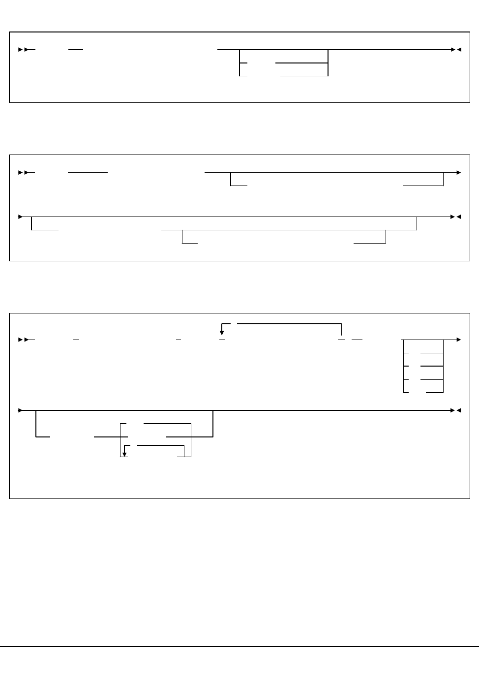
450 VM/HSC 6.0 System Programmer’s Guide
1st ed., 6/30/04 - 312579601
OPTion control statement
Reconfiguration Definition (RECDEF) control statement
Scratch Subpool (SCRPOol) control statement
OPTion TITLE(
identifying-string
)
TRACE
TRACEF
RECDEF DSN1(
dataset.name
)
,VOL1(
volser
),UNIT1(
unitname
)
,DSN2(
dataset.name
)
,VOL2(
volser
),UNIT2(
unitname
)
SCRPOol NAME(
subpool-name
),RANGE(
range-start-range-end
),LABEL(
SL
NL
AL
NSL
,HOSTID(
,
ALL
host-id
host-list
,
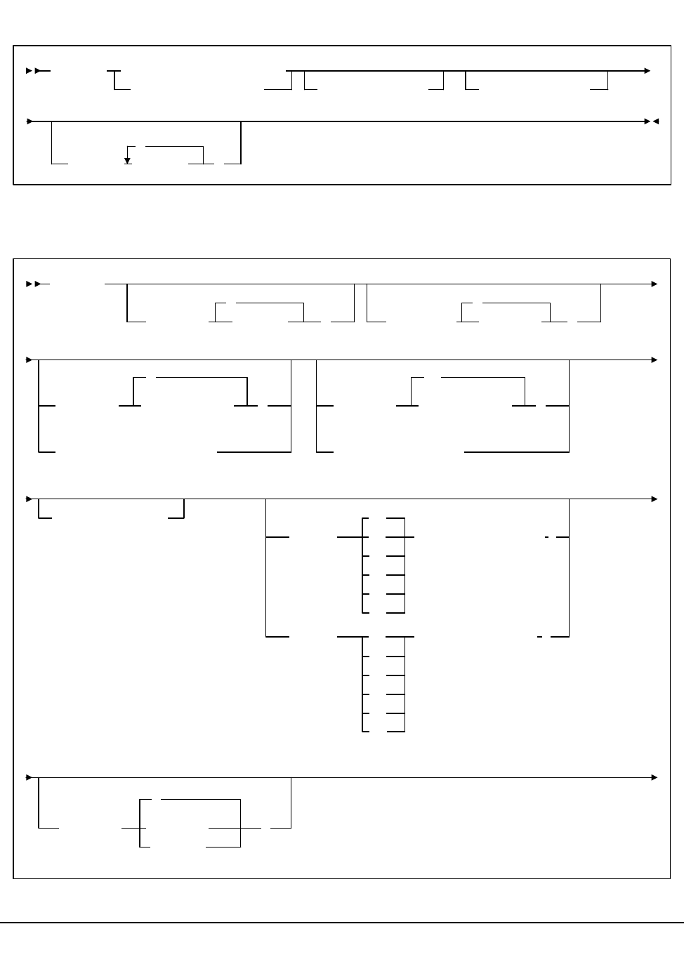
Appendix A. Macros, Control Statements, Utilities, and Commands Syntax Reference 451
1st ed., 6/30/04 - 312579601
Scratch Subpool Definition (SCRPDEF) command and control statement
Tape Request (TAPEREQ) control statement
SCRPDEF
DSN(dataset.name)
DATASET(dataset.name)
VOLume(volser)UNIT(unitname)
HOSTID( host-id
,
)
TAPEREQ
JOBname( jobname )
*
STEPname( stepname )
*
PROGram(
PGMname(program-name)
*
program-name )DATASET(
DSN(dataset-name)
**
dataset-name )
EXPDT(
RETPD( ,retention-period
NE
GT
LT
LE
EQ
GE
,expiration-date
EQ
NE
GT
LT
GE
LE
)
)
VOLType(
*
Specific
Nonspec
)
DDName(DD-name)

452 VM/HSC 6.0 System Programmer’s Guide
1st ed., 6/30/04 - 312579601
Tape Request (TAPEREQ) control statement (continued)
MEDia( LONGItud )
R
Standard
CST
MEDIA1
STD
1
3480
ECART
E
ECCST
ETAPE
Long
MEDIA2
3490E
ZCART
Z
HELical
DD3
DD3A
DD3B
DD3C
STK1
STK1R
STK2
STK2P
RECtech( LONGItud )
18track
36track
36Atrack
36Btrack
36Ctrack
HELical
DD3
STK1R
STK1R34
STK1R35
STK1RA
STK1RA34
STK1RA35
STK1RB
STK1RB34
STK1RB35
STK1RAB
STK1RC
STK1RC34
STK1RC35
STK2P
STK2P34
STK2P35
STK2PA
STK2PB
,
STK2PA34
STK2PA35
STK2PB34
STK2PB35
STK1RAB4
STK1RAB5
MODel( 4480 )
T9840C
T9840C35
4490
9490
9490EE
SD3
9840
984035
T9840B
T9840B35
T9940A
T9940A35
T9940B
T9940B35
,
model1
SUBPool(subpool-name)
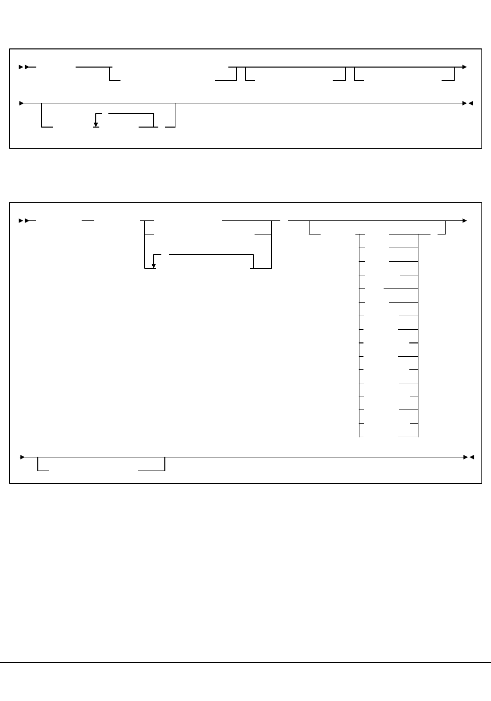
Appendix A. Macros, Control Statements, Utilities, and Commands Syntax Reference 453
1st ed., 6/30/04 - 312579601
Tape Request Definition (TREQDEF) command/control statement
Unit Attribute (UNITATTR) control statement
TREQDEF DATASET(
dataset.name
)
DSN(
dataset.name
)VOLume(
volser
)UNIT(
unitname
)
HOSTID(
host-id
,
)
UNITATTR ADDRess( )
MODel( 4480
4490
9490
9490EE
SD3
9840
)
unit-address
unit-address-list
unit-address-range
,
984035
NETHOST(host-id)
T9840B
T9840B35
IGNORE
T9940B35
T9940B
T9940A35
T9940A
T9840C35
T9840C
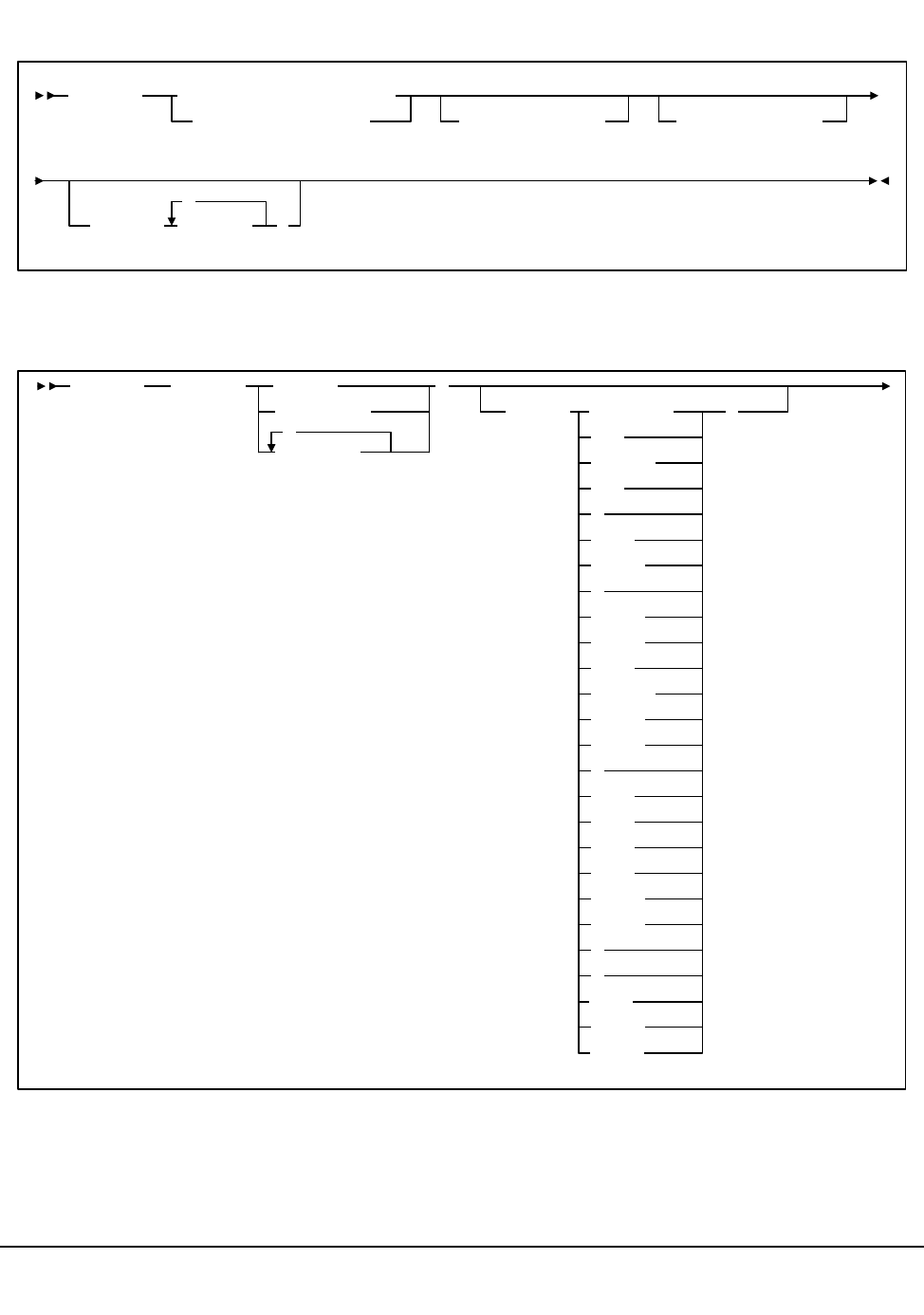
454 VM/HSC 6.0 System Programmer’s Guide
1st ed., 6/30/04 - 312579601
Unit Attribute Definition (UNITDEF) command/control statement
Volume Attribute (VOLATTR) control statement
UNITDEF DATASET(
dataset.name
)
DSN(
dataset.name
)VOLume(
volser
)UNIT(
unitname
)
HOSTID(
host-id
,
)
VOLATTR SERial( volser
vol-range
vol-list
,
)
MEDia( Standard
CST
MEDIA1
STD
1
3480
ECART
E
ECCST
ETAPE
Long
MEDIA2
3490E
ZCART
Z
DD3A
DD3B
DD3C
DD3D
STK1R
STK1U
R
U
)
STK2
STK2P
STK2W

Appendix A. Macros, Control Statements, Utilities, and Commands Syntax Reference 455
1st ed., 6/30/04 - 312579601
Volume Attribute (VOLATTR) control statement (continued)
RECtech( )MAXclean(use-limit)LONGItud
18track
36track
36Atrack
36Btrack
36Ctrack
HELical
DD3
STK1R
STK1R34
STK1R35
STK1RA
STK1RA34
STK1RA35
STK2PA
STK1RAB
STK1RAB4
STK1RAB5
STK1RC
STK1RC34
STK1RC35
STK1RB
STK1RB34
STK1RB35
STK2P
STK2P34
STK2P35
STK2PB
STK2PA34
STK2PA35
STK2PB34
STK2PB35

456 VM/HSC 6.0 System Programmer’s Guide
1st ed., 6/30/04 - 312579601
Volume Attribute Definition (VOLDEF) command/control statement
VOLDEF
DSN(dataset.name)
DATASET(dataset.name)
VOLume(volser)UNIT(unitname)
HOSTID( host-id
,
)
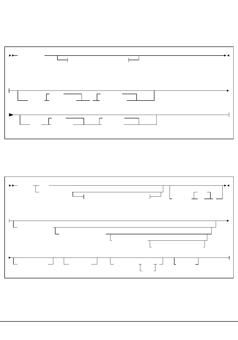
Appendix A. Macros, Control Statements, Utilities, and Commands Syntax Reference 457
1st ed., 6/30/04 - 312579601
Utilities
Refer to Chapter 4, “Utility Functions” on page 169 for more information on utility syntax
and parameters.
ACTIvities Report utility
AUDIt utility
ACTIvities
Optional Parameters
Optional Parameters:
BEGIN(
begin-date
TODAY
,
begin-time
00:00:00
END(
end-date
TODAY
end-time
23:59:59
AUDIt
Optional Parameters
Optional Parameters:
ACS(acs-id)
ALL
APPLy
(
NO
)
YES
LSM(lsm-list)
PANel(panel-list)
ROW(row-list)
COLumn(column-list)
CAP(cap-id)DIAGScan( )
ONLYEMPTYCel
ALSO
INTRANs
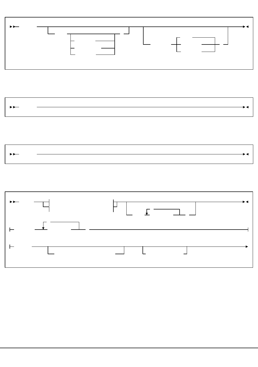
458 VM/HSC 6.0 System Programmer’s Guide
1st ed., 6/30/04 - 312579601
BACKup utility
Database Decompile (LIBGEN) utility
Directory Rebuild (DIRBLD) utility
EJECt utility
BACKup
CDS(
Primary
Secondary
STandby
)
OPTion(
Restart
Analyze
Copy
)
LIBGEN
DIRBLD
EJECt Eject Method 1
Eject Method 2
CAP( cap-list )
,
Eject Method 1:
Eject Method 2:
VOLser( vol-list
,
)
SCRTCH
SUBpool(subpool-name)VOLCNT(count)
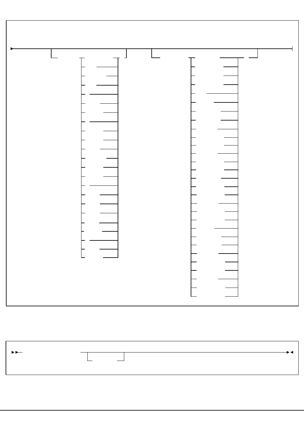
Appendix A. Macros, Control Statements, Utilities, and Commands Syntax Reference 459
1st ed., 6/30/04 - 312579601
EJECt utility (continued)
Enter Cartridges utility
Eject Method 2 (continued):
MEDia( Standard )
CST
MEDIA1
STD
1
3480
ECART
E
ECCST
ETAPE
Long
MEDIA2
3490E
ZCART
Z
DD3A
DD3B
DD3C
STK1R
R
STK2
RECtech( 18track
36Atrack
36Btrack
36Ctrack
DD3
)
STK1R
STK1R34
STK1R35
STK1RA
STK1RA34
STK1RA35
STK1RB
STK1RB34
STK1RB35
STK1
STK2P
STK2P
STK2P34
STK2P35
STK2PA
STK1RAB
STK1RAB4
STK1RAB5
STK1RC
STK1RC34
STK1RC35
STK2PA34
STK2PA35
STK2PB
STK2PB34
STK2PB35
ENTEr CAP(
cap-id
)
SCRatch
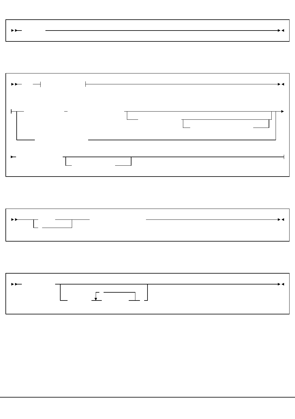
460 VM/HSC 6.0 System Programmer’s Guide
1st ed., 6/30/04 - 312579601
Journal OFFLoad utility
MOVe utility
Reconfiguration utility
REPLace utility
OFFLoad
MOVe
Parameters
Parameters:
Flsm(
lsm-id
)Panel(
panel-list
)
Volume(
vol-list
)
Row(
row-list
)
Column(
column-list
)
TLsm(
lsm-list
)
TPanel(
panel
)
START
S
reconfig-procname
REPLaceall
VOLser(
vol-list
,
)
Appendix A. Macros, Control Statements, Utilities, and Commands Syntax Reference 461
1st ed., 6/30/04 - 312579601
RESTore utility
SCRAtch utility
RESTore
APPly( NO
YES
)GENerate(
Only
Short
YES
NO
)
SCRAtch VOLser(
vol-list
,
)
462 VM/HSC 6.0 System Programmer’s Guide
1st ed., 6/30/04 - 312579601
Scratch Redistribution (SCREdist) utility
SCREdist ACS(acs-id)
LSM( lsm-list
,
)
SUBpool(subpool-name)
BALtol(tolerance-value)LONGItud
Standard
CST
MEDIA1
STD
1
3480
ECART
E
ECCST
ETAPE
Long
MEDIA2
3490E
ZCART
Z
HELical
DD3
DD3A
DD3B
DD3C
STK1
STK1R
R
LONGItud
18track
36track
36Atrack
36Btrack
36Ctrack
) )RECtech(MEDia(
HELical
DD3
STK1R
STK1R34
STK1R35
STK2
STK2P
STK1RA
STK1RA34
STK1RA35
STK1RB
STK1RB34
STK1RB35
STK2PA
STK1RAB
STK1RAB4
STK1RAB5
STK1RC
STK1RC34
STK1RC35
STK2P
STK2P34
STK2P35
STK2PB
STK2PA34
STK2PA35
STK2PB34
STK2PB35
Appendix A. Macros, Control Statements, Utilities, and Commands Syntax Reference 463
1st ed., 6/30/04 - 312579601
SET utility
SET Options
Options:
ACSDRV(esoteric),FORACS(acs-id)
,FORHOST(host-id)
CLNPRFX(prefix)
COMPRFX(cmdhex)
DELDISP( SCRTCH
NOSCRTCH
)
HOSTID (newhost),FORHOST(oldhost)
HSCLEVEL(OFF),FORHOST(host-id)
MAJNAME(qname)
FREEZE( ON )
OFf
,FORLSMID(lsm-id),FORPANEL(panel)
EJCTPAS(
newpswd
)
,OLDPASS(oldpswd)
NNLBDRV(
esoteric
)
,FORHOST(host-id)
SCRLABL( )SL
AL
NL
NSL
NEWHOST(newhost),LIKEHOST(model-host)
464 VM/HSC 6.0 System Programmer’s Guide
1st ed., 6/30/04 - 312579601
SET utility (continued)
UNSCratch utility
Unselect utility
SET
Options
Options:
SMF(libtype)
TCHNIQE(
JOURNAL
SHADOW
BOTH
STANDBY
ALL
NONE )
SLIDRIVS(
addr0
,...addr19
),FORLSMID(lsm-id),FORPANEL(panel)
,FORHOST(host-id)
SLISTATN(
stat1,...,stat16
),FORACS(acs-id)
,FORHOST(host-id)
UNSCratch VOLser(
vol-list
,
)
UNSElect VOLser(
volser
)
,FORCE
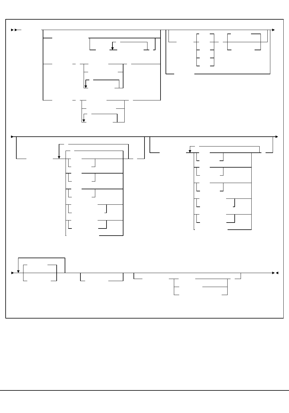
Appendix A. Macros, Control Statements, Utilities, and Commands Syntax Reference 465
1st ed., 6/30/04 - 312579601
Volume Report (VOLRpt) utility
VOLRpt
ACS(
acs-id
)
LSM(
lsm-list
,
)
VOLser (
volser
vol-range
vol-list
,
)
VOLume (
volser
vol-range
vol-list
,
)
SORT(
LOC
INS
VOL
SEL
USE
)
DEScend
ASCend
NOSORT
INCLude(
,
*
SCR
NONSCR
ERR
NONERR
SEL
NONSEL
READable
UNREADable
MEDEQUAL
NONMEDEQ
)
EXCLude(
,
SCR
NONSCR
ERR
NONERR
SEL
NONSEL
READable
UNREADable
MEDEQUAL
NONMEDEQ
)
NOEXTernal
NOEXTernal
VOLDATA
VOLIST
CDSDATA SUMMary( TOTal
SUBpool
TOTal,SUBpool
)
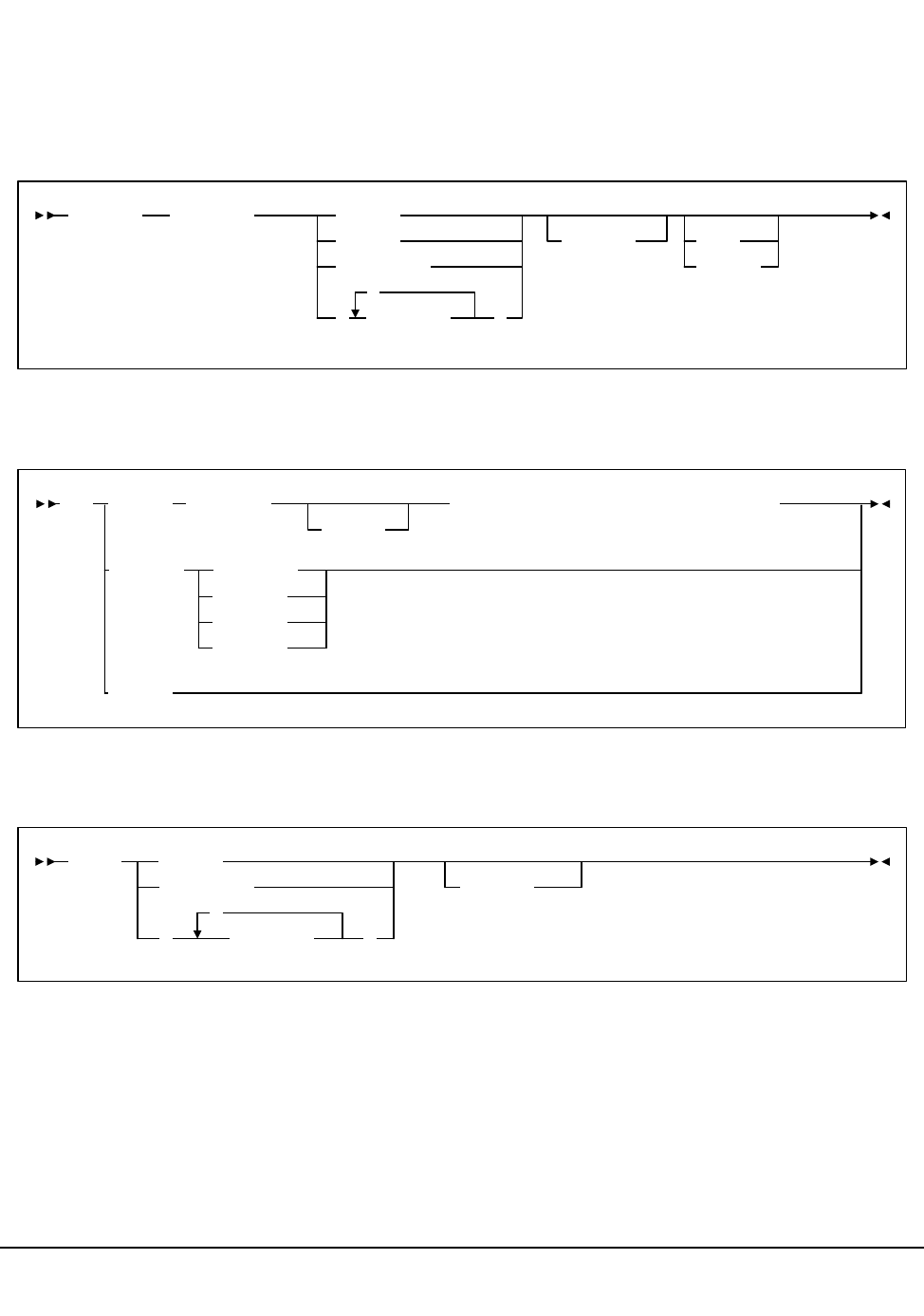
466 VM/HSC 6.0 System Programmer’s Guide
1st ed., 6/30/04 - 312579601
Operator Commands
Refer to ‘‘Operator commands’’ in the HSC Operator’s Guide for complete explanations
of command syntax and parameters.
CAP Preference (CAPPref) command and control statement
CDs Enable/Disable command
CLean command
CAPPref
prefvlue lsm-id
cap-id
cap-range
(
cap-list
,
)
host-id
AUTO
MANual
Primary
SEcndry
STandby
DSn(dsn)
Disable
DSn(dsn)CDs Enable NEWVol(volser),NEWUnit(unitname)
NEWLoc
EXpand
CLean
dev-range
dev-id
(dev-list
,
)
host-id
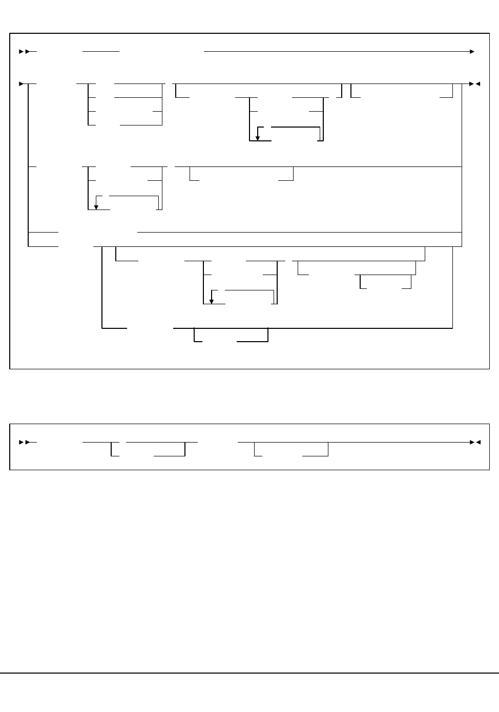
Appendix A. Macros, Control Statements, Utilities, and Commands Syntax Reference 467
1st ed., 6/30/04 - 312579601
Communications Path (COMMPath) command and control statement
DISMount command
COMMPath HOSTid(host-id)
METHod(
LMU
CDS
LMU,acs-id
VTAM
)
LMUpath( acs-id
acs-range
acs-list
,
)VTAMpath(name)
LMUpath( acs-id
acs-range
acs-list
,
)
VTAMpath(name)
VTAMpath(name)
DELete
LMUpath( acs-id
acs-range
acs-list
,
)
VTAMpath
(name)
VTAMpath
(name)
DISMount
volser
,devaddr
host-id
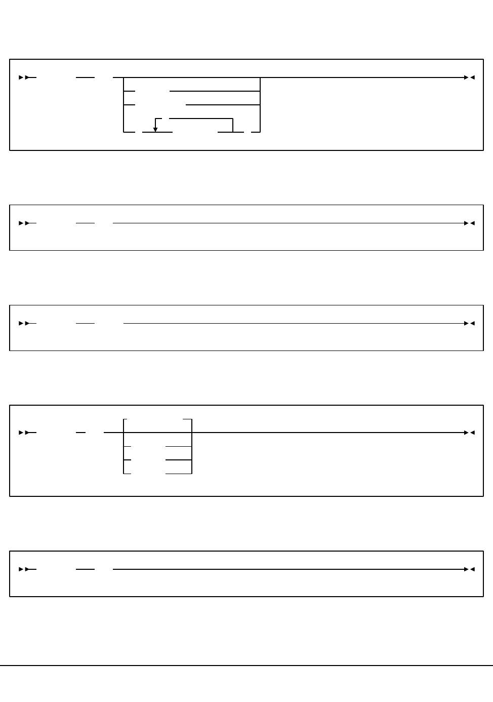
468 VM/HSC 6.0 System Programmer’s Guide
1st ed., 6/30/04 - 312579601
Display command
Display Acs
Display ALl
Display ALLOC
Display Cap
Display CDS
Display
acs-id
Acs
(acs-list
,
)
acs-range
Display ALl
Display ALLOC
Display
(all CAPs)
Cap
acs-id
lsm-id
cap-id
Display CDS
Appendix A. Macros, Control Statements, Utilities, and Commands Syntax Reference 469
1st ed., 6/30/04 - 312579601
Display Cmd
Display COMMPath
Display DRives
Display command-name
COmmand
CMd
Display COMMPath
HOSTid( ALL
host-id
*
,
host-list
)
Display DRives
Library
ACS(acs-id)
LSM(lsm-id)
ACtive
ALl
Idle
DETail
470 VM/HSC 6.0 System Programmer’s Guide
1st ed., 6/30/04 - 312579601
Display Drives (continued)
MEDia( LONGItud
Standard
CST
MEDIA1
STD
1
3480
ECART
E
ECCST
ETAPE
Long
MEDIA2
3490E
ZCART
Z
HELical
DD3
DD3A
DD3B
DD3C
DD3D
STK1
STK1R
R
STK1U
U
RECtech( LONGItud ))
STK2
STK2P
STK2W
18track
36track
36Atrack
36Btrack
36Ctrack
HELical
DD3
STK1R
STK1R34
STK1R35
STK1RA
STK1RA34
STK1RA35
STK1RB
STK1RB34
STK1RB35
STK2P
)
STK1RAB
STK1RAB4
STK1RAB5
STK1RC
STK1RC34
STK1RC35
STK2P34
STK2P35
STK2PB
MODel( 4480
4490
9490
9490EE
SD3
9840
984035
T9840B
T9840B35
T9840C
T9840C35
T9940A
T9940A35
T9940B
T9940B35
IGNORE
STK2PA
STK2PA34
STK2PA35
STK2PB34
STK2PB35
IGNORE
Appendix A. Macros, Control Statements, Utilities, and Commands Syntax Reference 471
1st ed., 6/30/04 - 312579601
Display Exceptions
Display LKEYDEF
Display LMUPDEF
Display LSM
Display Message
Display MNTD
Display EXceptns
X
Display LKEYDEF
Display LMUPDEF
Display Lsm
lsm-id
lsm-range
(
,
lsm-list )
Display Message
Msg
msgnum
Display MNTD
472 VM/HSC 6.0 System Programmer’s Guide
1st ed., 6/30/04 - 312579601
Display MONitor
Display OPTion
Display Requests
Display MONitor
,PGMI ,L(
name
cc )
Display OPTion
Display Requests
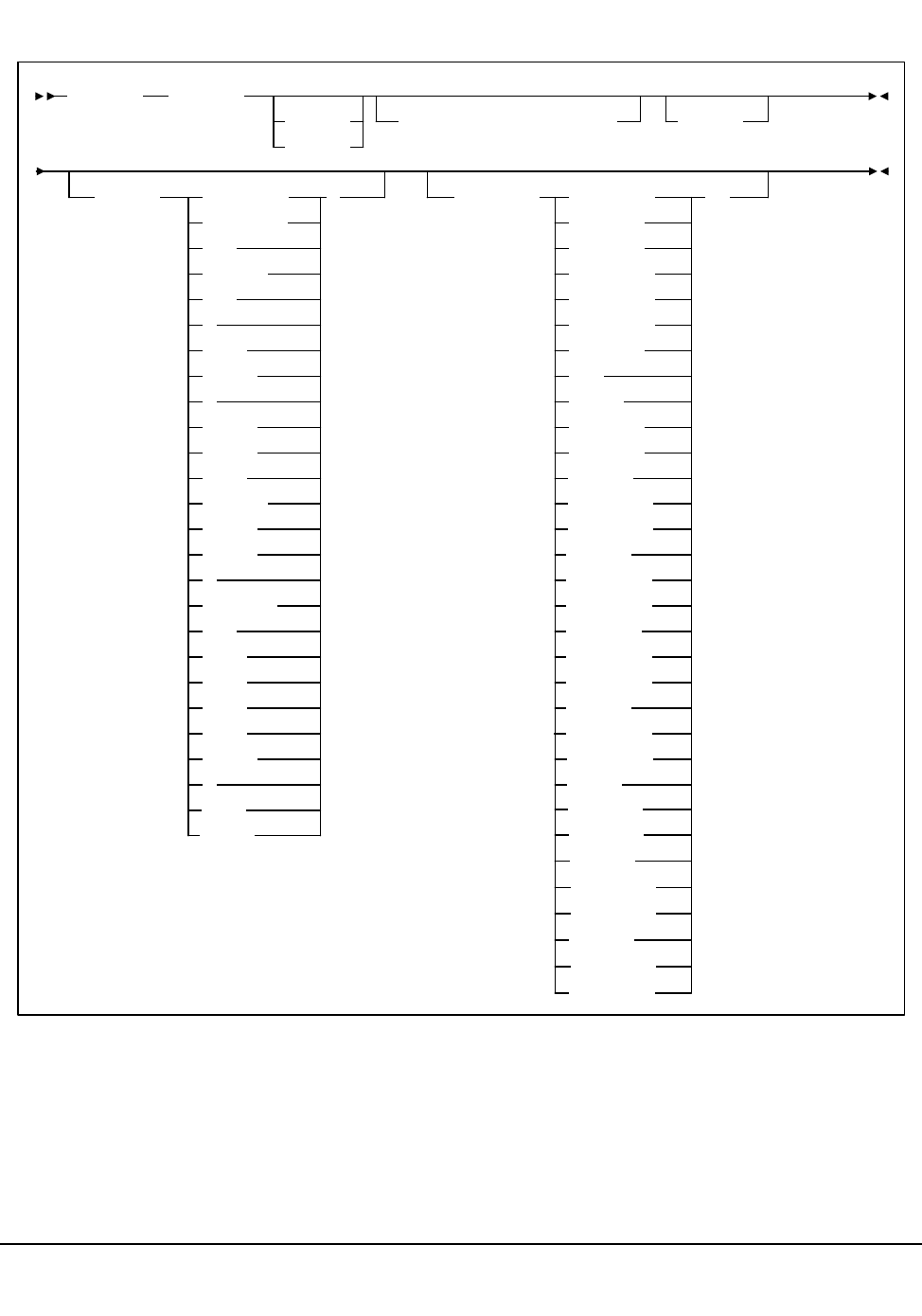
Appendix A. Macros, Control Statements, Utilities, and Commands Syntax Reference 473
1st ed., 6/30/04 - 312579601
Display SCRatch
Display SCRatch
acs-id
lsm-id
SUBpool(subpool-name)DETail
MEDia(
Standard
LONGItud )
CST
MEDIA1
STD
1
3480
ECART
E
ECCST
ETAPE
Long
MEDIA2
3490E
ZCART
Z
HELical
DD3
DD3A
DD3B
DD3C
STK1
STK1R
R
RECtech( LONGItud
18track
36track
36Atrack
36Btrack
36Ctrack
HELical
DD3
STK1R
STK1R34
STK1R35
)
STK2
STK2P
STK1RA
STK1RA34
STK1RA35
STK1RB
STK1RB34
STK1RB35
STK1RAB
STK1RAB4
STK1RAB5
STK1RC
STK1RC34
STK1RC35
STK2P
STK2P34
STK2P35
STK2PA
STK2PA34
STK2PA35
STK2PB
STK2PB34
STK2PB35

474 VM/HSC 6.0 System Programmer’s Guide
1st ed., 6/30/04 - 312579601
Display SCRPDEF
Display SRVlev
Display Status
Display SCRPDEF
Display SRVlev
Display Status
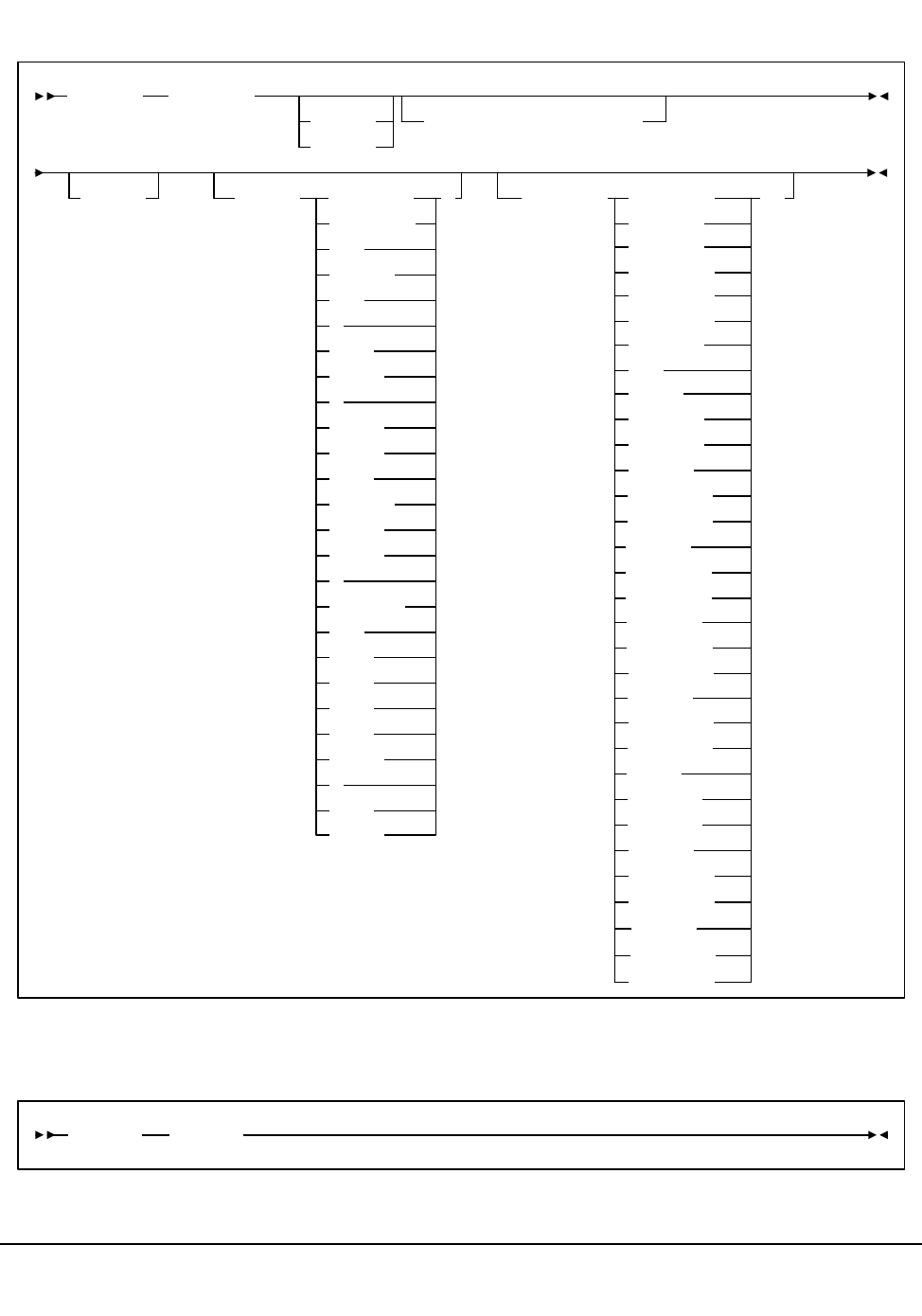
Appendix A. Macros, Control Statements, Utilities, and Commands Syntax Reference 475
1st ed., 6/30/04 - 312579601
Display THReshld
Display TREQDEF
Display THReshld
acs-id
lsm-id
SUBpool(subpool-name)
DETail MEDia(
Standard
LONGItud )
CST
MEDIA1
STD
1
3480
ECART
E
ECCST
ETAPE
Long
MEDIA2
3490E
ZCART
Z
HELical
DD3
DD3A
DD3B
DD3C
STK1
STK1R
R
RECtech(
STK1R34
18track
LONGItud
36track
36Atrack
36Btrack
36Ctrack
HELical
DD3
STK1R
)
STK1R35
STK2
STK2P
STK1RA
STK1RA34
STK1RA35
STK1RB
STK1RB34
STK1RB35
STK2PA
STK1RAB
STK1RAB4
STK1RAB5
STK1RC
STK1RC34
STK1RC35
STK2P
STK2P34
STK2P35
STK2PB
STK2PA34
STK2PA35
STK2PB34
STK2PB35
Display TREQDEF
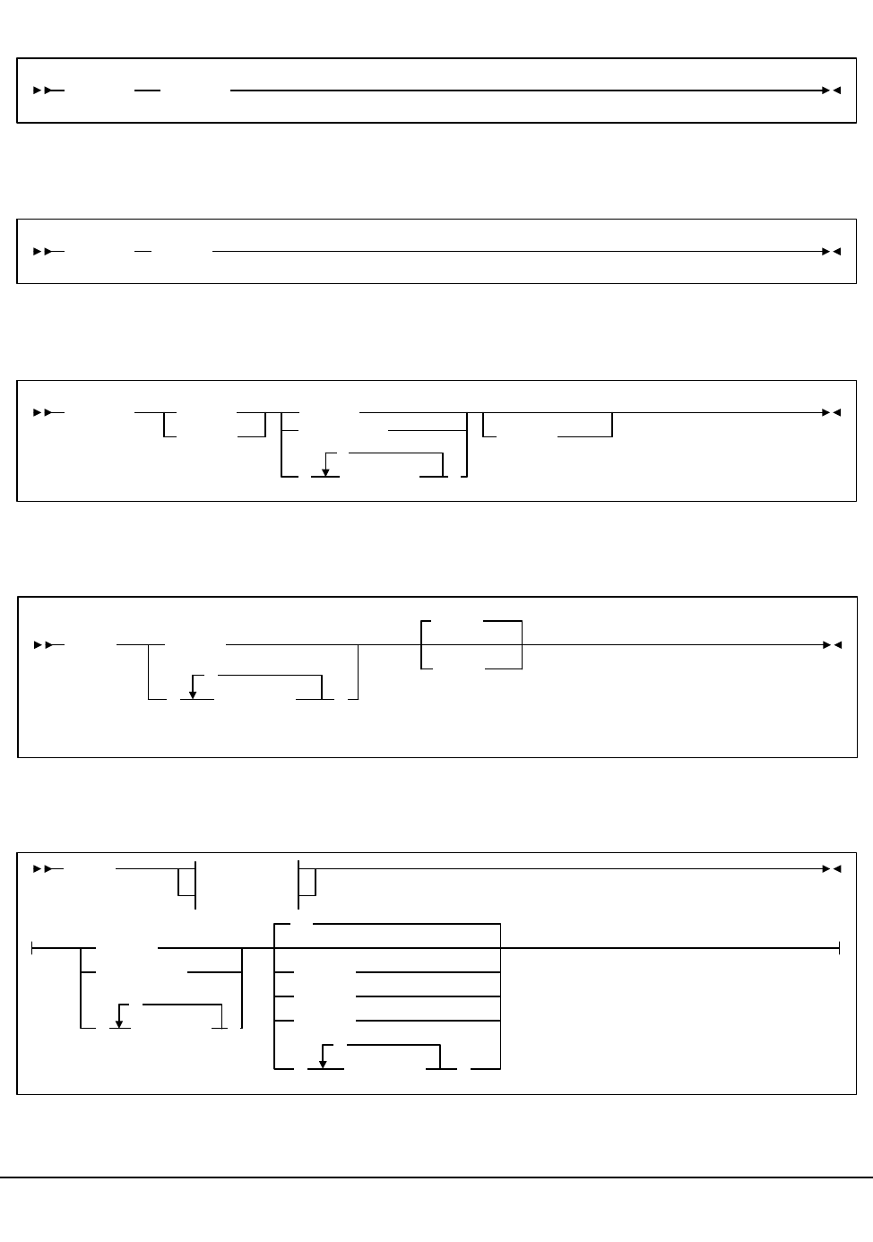
476 VM/HSC 6.0 System Programmer’s Guide
1st ed., 6/30/04 - 312579601
Display UNITDEF
Display VOLDEF
Display Volume
DRAin CAP command
EJect command
Display UNITDEF
Display VOLDEF
Display
Volume
Volser
vol-range
volser
(vol-list
,
)
DETail
DRAin cap-id
EJect
ENter
( )cap-list
,
EJect
Option 2
Option 1
Option 1:
vol-range
volser
(vol-list
,
)
acs-id
lsm-id
cap-id
(cap-list )
,
00
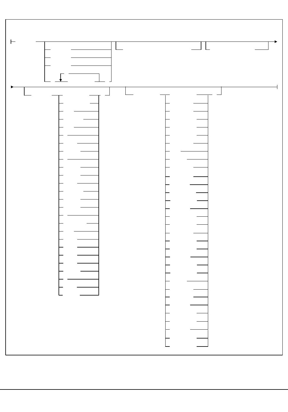
Appendix A. Macros, Control Statements, Utilities, and Commands Syntax Reference 477
1st ed., 6/30/04 - 312579601
Eject Command (continued)
)
Option 2:
SCRTCH
acs-id
lsm-id
cap-id
(cap-list )
,
SUBpool(subpool-name)
MEDia( LONGItud )
Standard
CST
MEDIA1
STD
1
3480
ECART
E
ECCST
ETAPE
Long
MEDIA2
3490E
ZCART
Z
HELical
DD3
DD3A
DD3B
DD3C
STK1
STK1R
R
RECtech( )
STK1R34
LONGItud
18track
36track
36Atrack
36Btrack
36Ctrack
HELical
DD3
STK1R
STK1R35
STK2
STK2P
VOLCNT(count
STK1RA
STK1RA34
STK1RA35
STK1RB
STK1RB34
STK1RB35
STK2P35
STK2P
STK2P34
STK2PA
STK1RAB
STK1RAB4
STK1RAB5
STK1RC
STK1RC34
STK1RC35
STK2PA34
STK2PA35
STK2PB
STK2PB35
STK2PB34
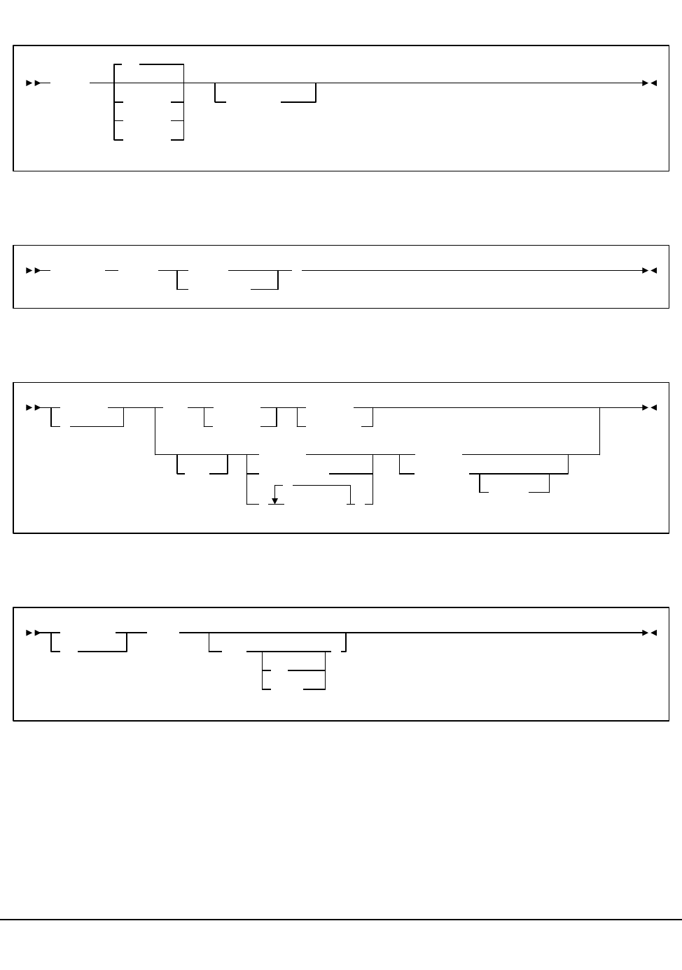
478 VM/HSC 6.0 System Programmer’s Guide
1st ed., 6/30/04 - 312579601
ENter command
Journal command
MODify command
MONITOR command
ENter
acs-id
cap-id
lsm-id
00
SCRatch
Journal Full(
Continue
ABEND )
F
MODify CAP
cap-id
lsm-id
ONline
OFFline
LSM
lsm-id
lsm-range
(
lsm-list
,
)
ONline
OFFline
FORCE
MN
MONITOR PGMI
,L(
cc
name
)
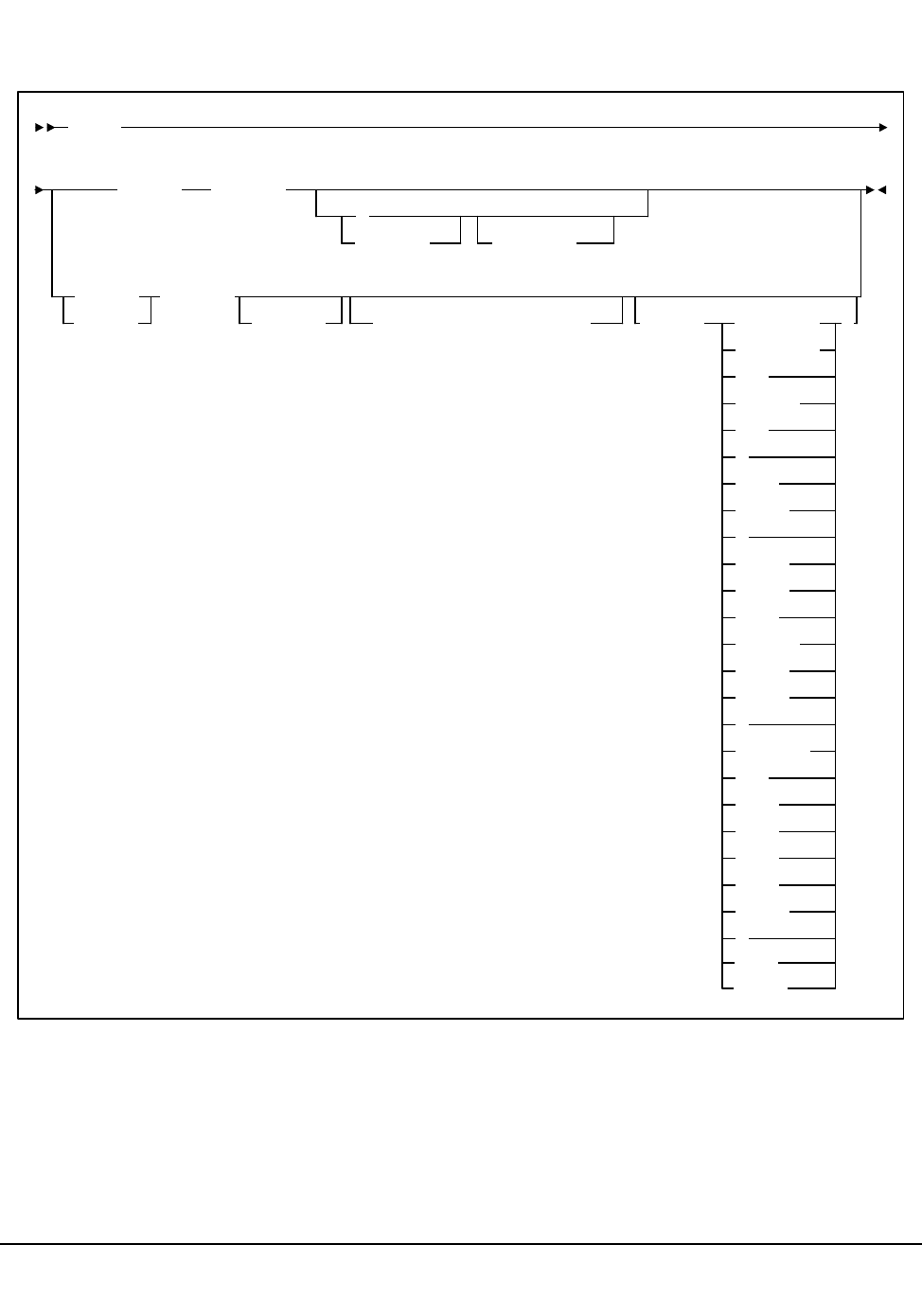
Appendix A. Macros, Control Statements, Utilities, and Commands Syntax Reference 479
1st ed., 6/30/04 - 312579601
Mount command
Mount
volser devaddr
host-id
,
Readonly
SCRTCH devaddr
host-id SUBpool(subpool-name)MEDia( )LONGItud
Standard
CST
MEDIA1
STD
1
3480
ECART
E
ECCST
ETAPE
Long
MEDIA2
3490E
ZCART
Z
HELical
DD3
DD3A
DD3B
DD3C
STK1
STK1R
R
PRIVAT
STK2
STK2P
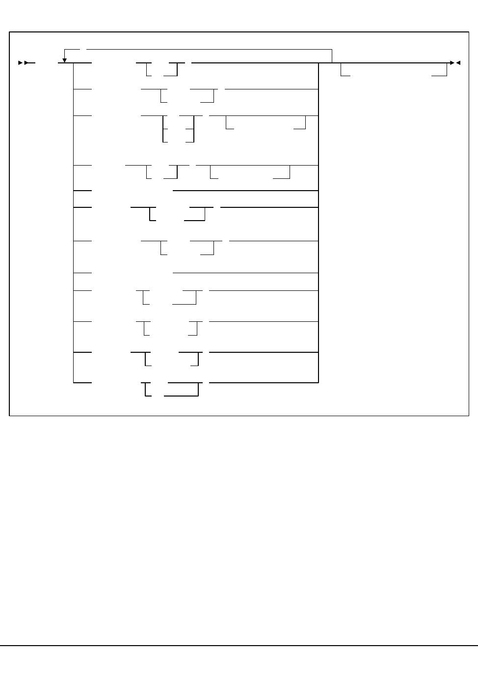
480 VM/HSC 6.0 System Programmer’s Guide
1st ed., 6/30/04 - 312579601
Mount/Dismount Options (MNTD) command and control statement
MNTD AUtocln(
ON
OFf )
,
Dismount( Auto
Manual
)
EJctauto( ON
MSg
OFf
)
ACS(
acs-id
)
Float(
ON
OFf )
ACS(
acsid
)
MAXclean(
count
)
MMount( Delete
Reply
)
MOuntmsg( Roll
Noroll
)
PASSTHRU(
count
)
Scratch( Manual
Auto
)
SCRDISM( CURRENT )
Unload( Noscr )
ARCHIVE
Scratch
VOLWatch( OFf )
ON
HOSTID(
host-id
)
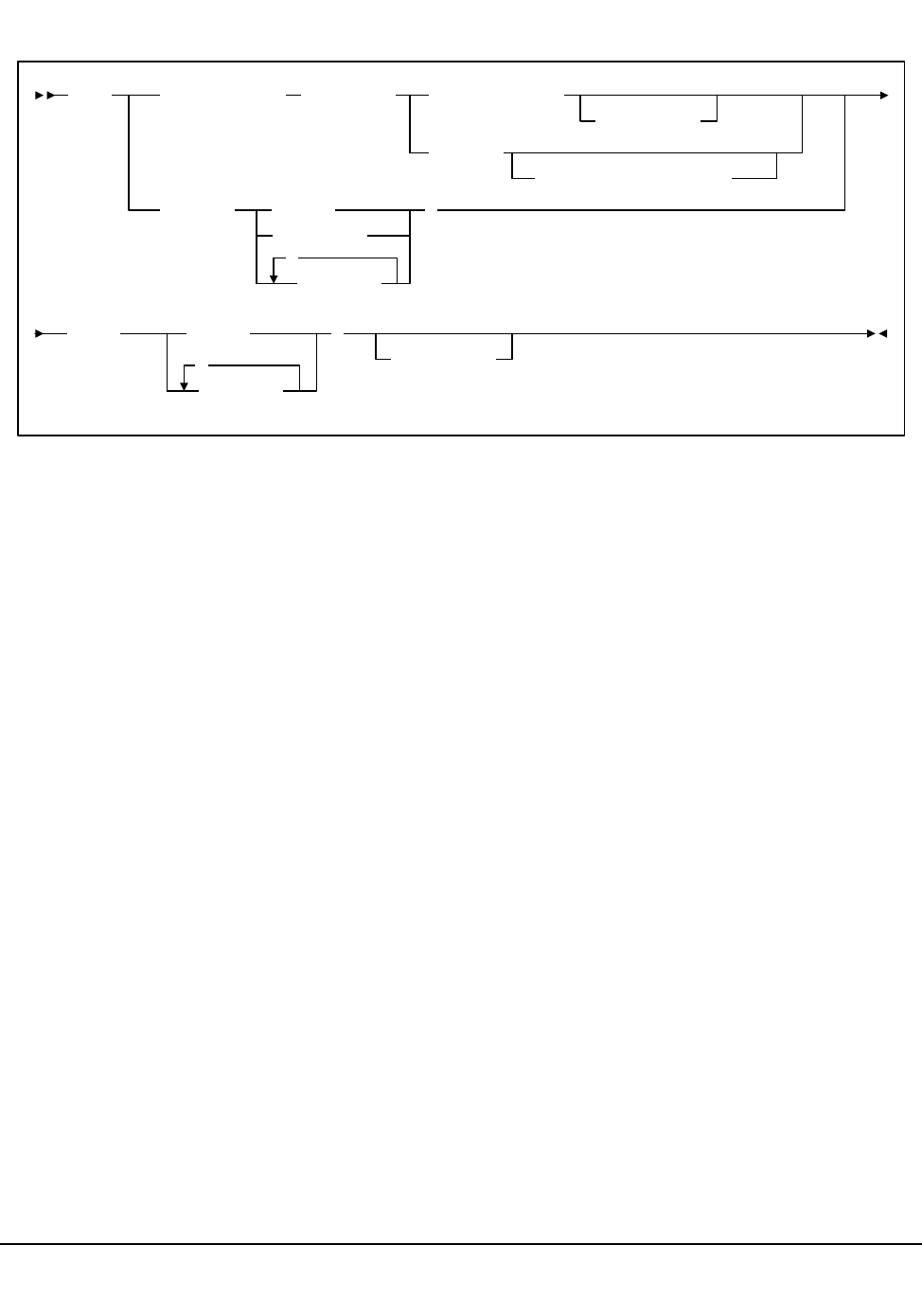
Appendix A. Macros, Control Statements, Utilities, and Commands Syntax Reference 481
1st ed., 6/30/04 - 312579601
MOVe command
MOVe Flsm(lsm-id)Panel(pp)Row(row-list)
Column(cc)
Row(rr)
Column(column-list)
Volume(
vol-range
volser
vol-list
,
)
TLsm( lsm-id
lsm-list
,
)
TPanel(pp)
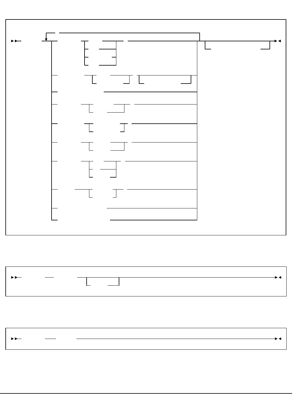
482 VM/HSC 6.0 System Programmer’s Guide
1st ed., 6/30/04 - 312579601
OPTion command and control statement
RECover Host command
RELease CAP command
OPTion Dialog( Both
Log
Console
Off
)
,
HOSTID(host-id)
DISCmsg( SHow
SUppress
)
ACS(acs-id)
EJLimit(count)
ENTdup(
Auto
Manual )
LOGging( Standard
Extended
)
Output( Upper
Mixed
)
Repath( Yes
No
)
Reply
Viewtime(count)
Warnmsg(minutes)
SWAP( MVSmsg
HSCmsg
)
RECover host-id
FORCE
RELease cap-id
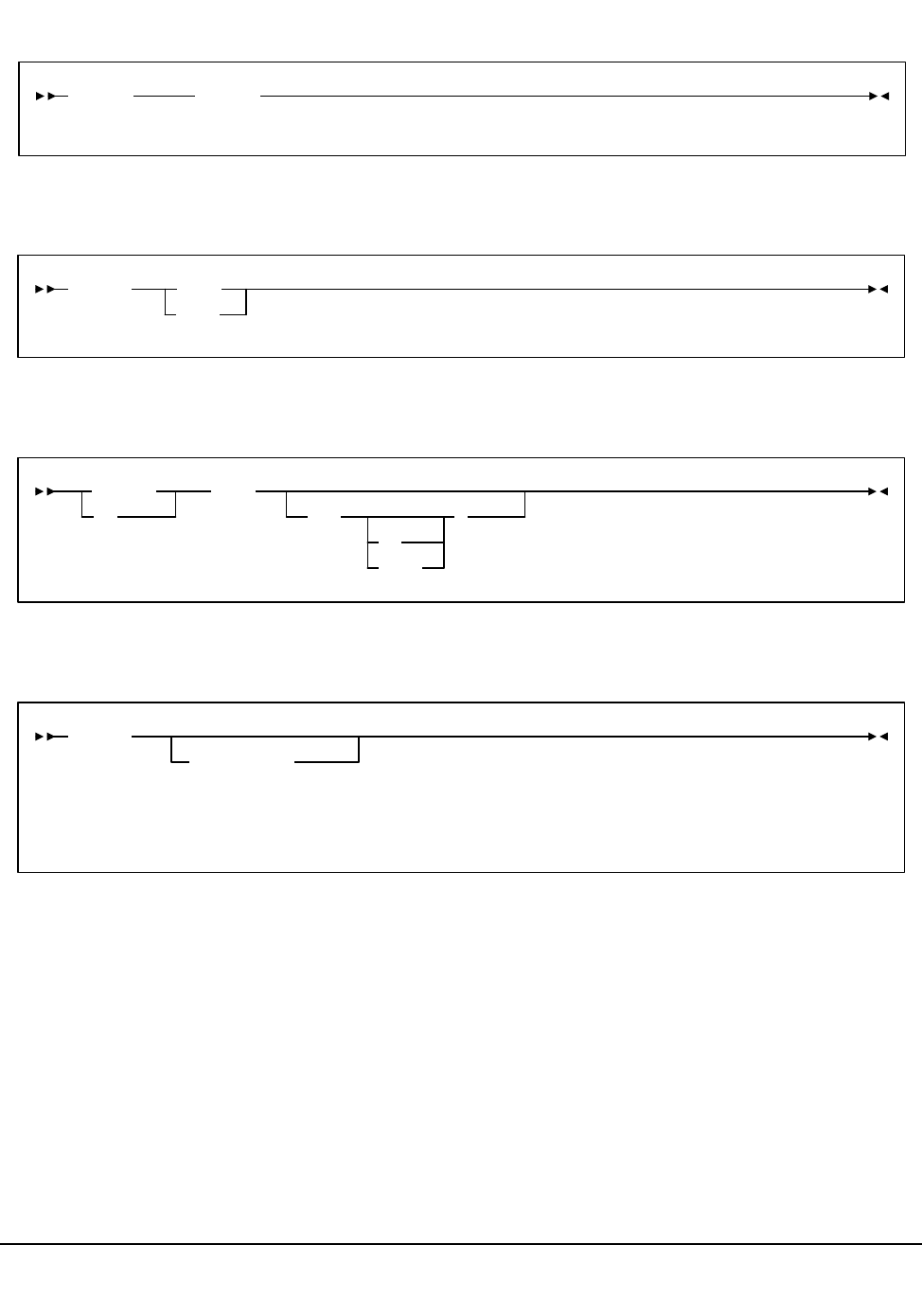
Appendix A. Macros, Control Statements, Utilities, and Commands Syntax Reference 483
1st ed., 6/30/04 - 312579601
SENter command
SRVlev (Service Level) command
Stop Monitoring (STOPMN) command
SWitch command
SENter cap-id
SRVlev BASE
FULL
STOPMN
PM
PGMI
,L(
cc
name
)
SWitch
Acs acs-id
(1)
Note:
(1) ACS acs-id is optional in a single-ACS environment; it is required in a multiple-ACS
environment.
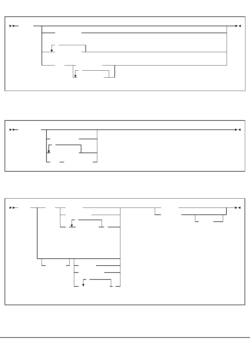
484 VM/HSC 6.0 System Programmer’s Guide
1st ed., 6/30/04 - 312579601
TRace command
TRACELKP command
Vary Station command
TRace
comp-name
comp-list
,
OFF comp-name
comp-list
,
TRACELKP
table-name
table-list
,
OFF table-name
Vary
acs-range
acs-id
(acs-list
,
)
OFFline
ONline
FORCE
ACS
dev-id
dev-range
( dev-list
,
STation
)
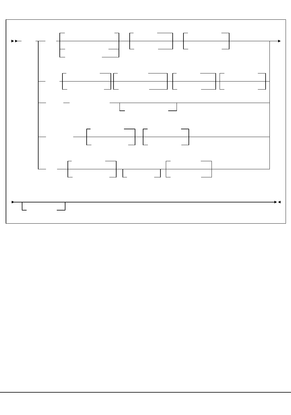
Appendix A. Macros, Control Statements, Utilities, and Commands Syntax Reference 485
1st ed., 6/30/04 - 312579601
VIew command
VIew CAp
CAPID(cap-id)
Lsm(lsm-id)
CAPID(00:00:00)
CEll
Row(rr)
Row(00)Lsm(00:00)
Lsm(lsm-id)Panel(pp)
Panel(00)
Column(cc)
Column(00)
Column(cc)
Column(00)
DRive Address(xxx)
Host(host-id)
PLaygrnd
Lsm(00:00)
Lsm(lsm-id)Column(cc)
Column(00)
PTp
Lsm(00:00)
Lsm(lsm-id)Xlsm(ll)Column(c)
Column(0)
Time(ttt)
Row(rr)
Row(00)
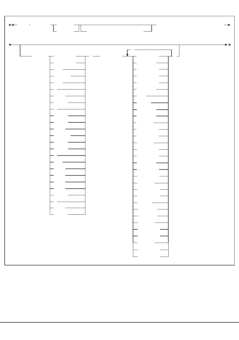
486 VM/HSC 6.0 System Programmer’s Guide
1st ed., 6/30/04 - 312579601
Warn command
Warn SCRatch
lsm-id
acs-id
SUBpool(subpool-name)
THReshld(threshold-value)
MEDia( LONGItud
Standard
)RECtech( LONGItud
,
)
CST
MEDIA1
STD
1
3480
ECART
E
ECCST
ETAPE
Long
MEDIA2
3490E
ZCART
Z
DD3
DD3A
DD3B
DD3C
STK1
STK1R
R
STK2
STK2P
18track
36Atrack
36Btrack
36Ctrack
HELical
DD3
STK1R
STK1R34
STK1R35
STK1RA
STK1RA34
STK1RA35
STK1RB
STK1RB34
STK1RB35
STK1RAB
STK1RAB4
STK1RAB5
STK1RC
STK1RC34
STK1RC35
STK2P
STK2P34
STK2P35
STK2PA
STK2PB
STK2PA34
STK2PA35
STK2PB34
STK2PB35
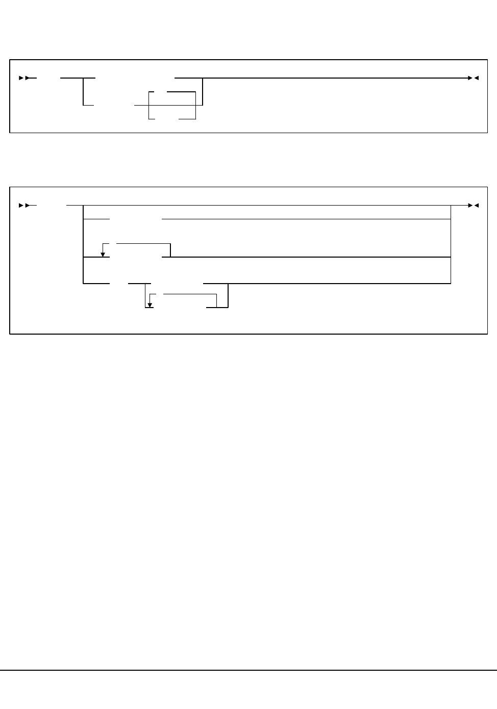
Appendix A. Macros, Control Statements, Utilities, and Commands Syntax Reference 487
1st ed., 6/30/04 - 312579601
HSC Diagnostic Commands
LIst command
TRace command
LIst data-structure
address
size
16
TRace
comp-name
comp-list
,
OFF comp-name
comp-list
,
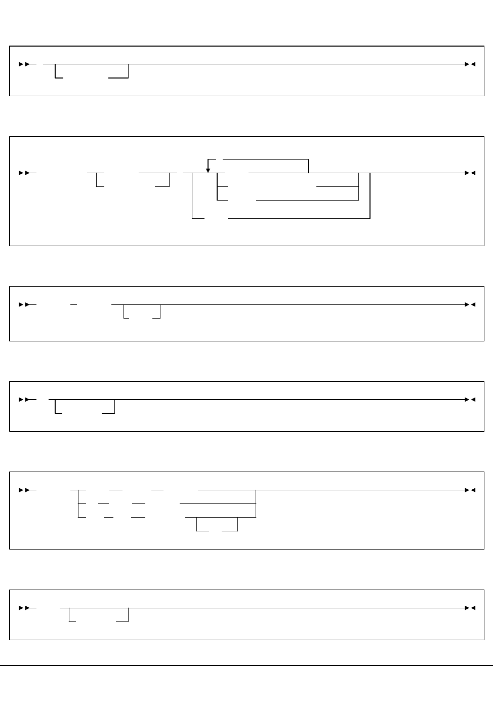
488 VM/HSC 6.0 System Programmer’s Guide
1st ed., 6/30/04 - 312579601
SCP Operator Commands
* (comment) Statement
AUTHorize Command
CANCEL command
CP Command
DEFine Command
DUMP Command
*
comments
AUTHorize
user-list
userid (
,
CMDS
MSGS route-codes
NETVM
NONE
CANCEL taskid
DUMP
CP
cmdparm
DEFine
CU
DEV
CHAN chnum chtype
chcu cutype
cuu devtype
id
DUMP
comment
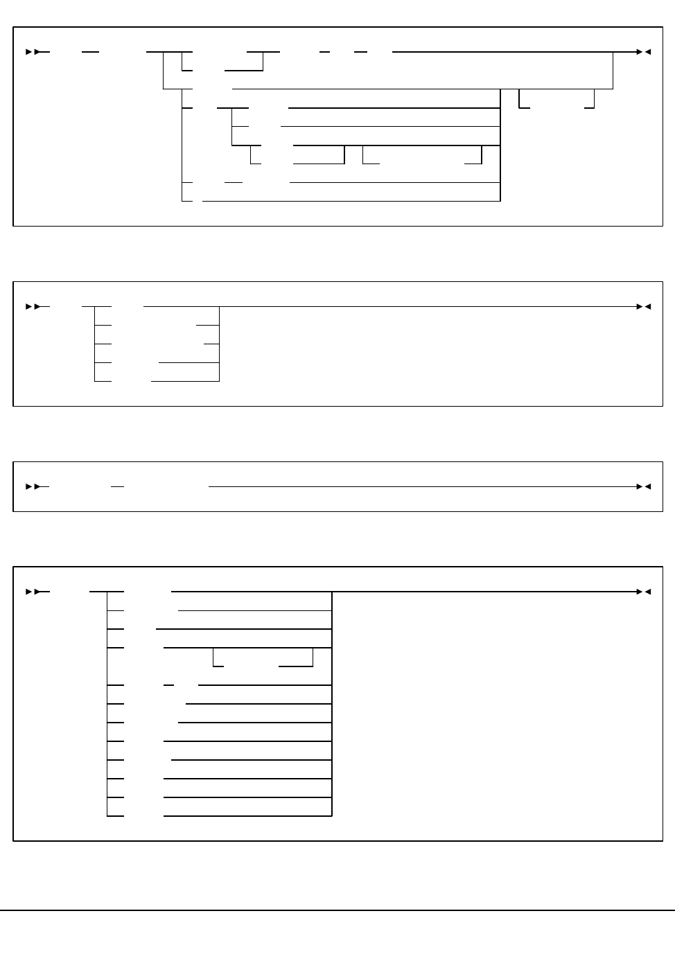
Appendix A. Macros, Control Statements, Utilities, and Commands Syntax Reference 489
1st ed., 6/30/04 - 312579601
FILE Command
HELP Command
Modify Command (SCP)
Query Command
FILE ddname BLOCKIO
DISK
CLEAR
DEV vaddr
CARD
PNCH
PRNT CLass class
DSN dsn
IUCV userid
*
vaddr DSN dsn
HELP HELP
scp-command
diag-command
msgnum
topic
taskname hsc-command
Query Active
Conslog
Dump
Files
jobname
Label
Operator
Perflog
Reply
System
Trace
Units
Vstor
cuu
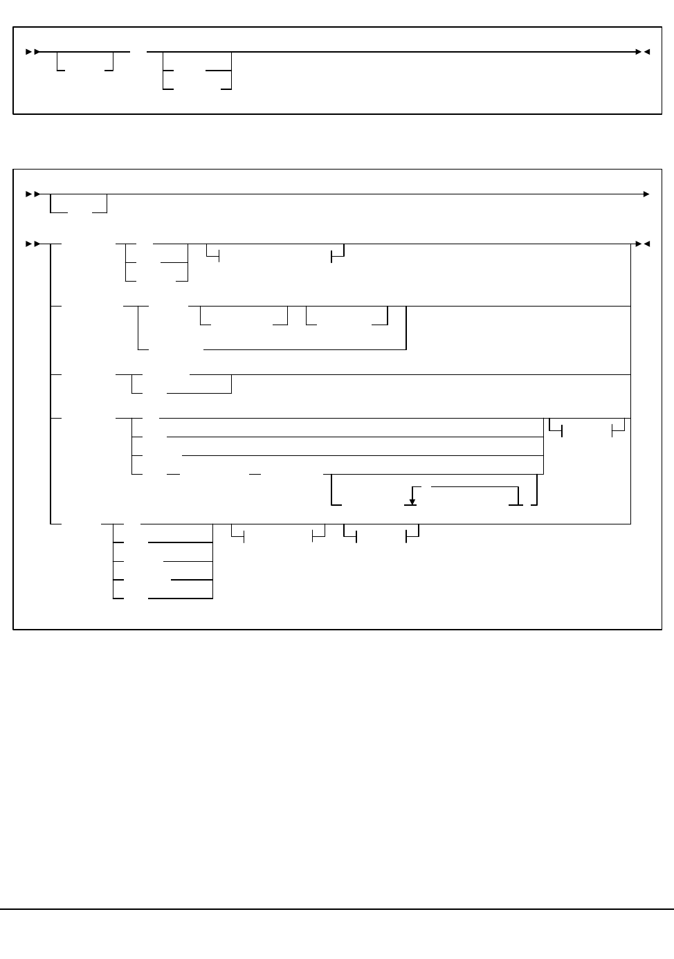
490 VM/HSC 6.0 System Programmer’s Guide
1st ed., 6/30/04 - 312579601
Reply Command
SET Command
Reply
nn
text
'text'
CONSlog
SET
ON
OFF
CLOSE
destination
DUMPOpts REset
maxcount (userid
(userid
MSGtype MSGNOH
MSG
PERFlog ON
OFF
CLOSE
SMF subsystem interval
SUBTYPE( subtype-list
,
)
dest.
TRACE ON
OFF
CLOSE
SELect
SET
events dest.
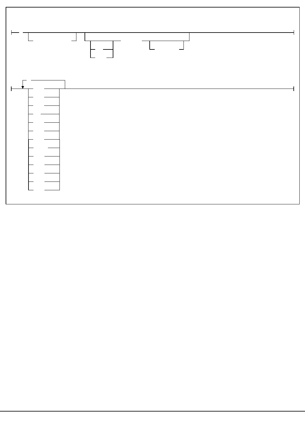
Appendix A. Macros, Control Statements, Utilities, and Commands Syntax Reference 491
1st ed., 6/30/04 - 312579601
(
Class class
TO
FOR
userid
AT node
,
ALL
DSP
EXT
IO
I/O
IUC
MCK
destination:
events:
NONE
PGM
RST
SIO
SVC
USR
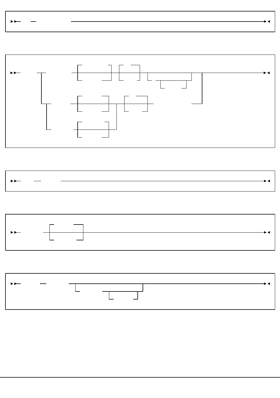
492 VM/HSC 6.0 System Programmer’s Guide
1st ed., 6/30/04 - 312579601
SLK Command
STArt Command
STOP Command
STOPSCP Command
SUBSYS Command
SLK scp-command
STArt progname
progname
taskid
50
prio (
parms
JOBRDR
AUTHRDR
JOBRDR
taskid
AUTHRDR
taskid
50
prio
(CLass class
STOP taskid
STOPSCP
(REIPL
(LOGOFF
SUBSYS sysname
initpgm
(parms

Appendix A. Macros, Control Statements, Utilities, and Commands Syntax Reference 493
1st ed., 6/30/04 - 312579601
GCS Component Server Commands
SLKGCS Command
SLKGCS START
DISPLAY
STOP
CANCEL
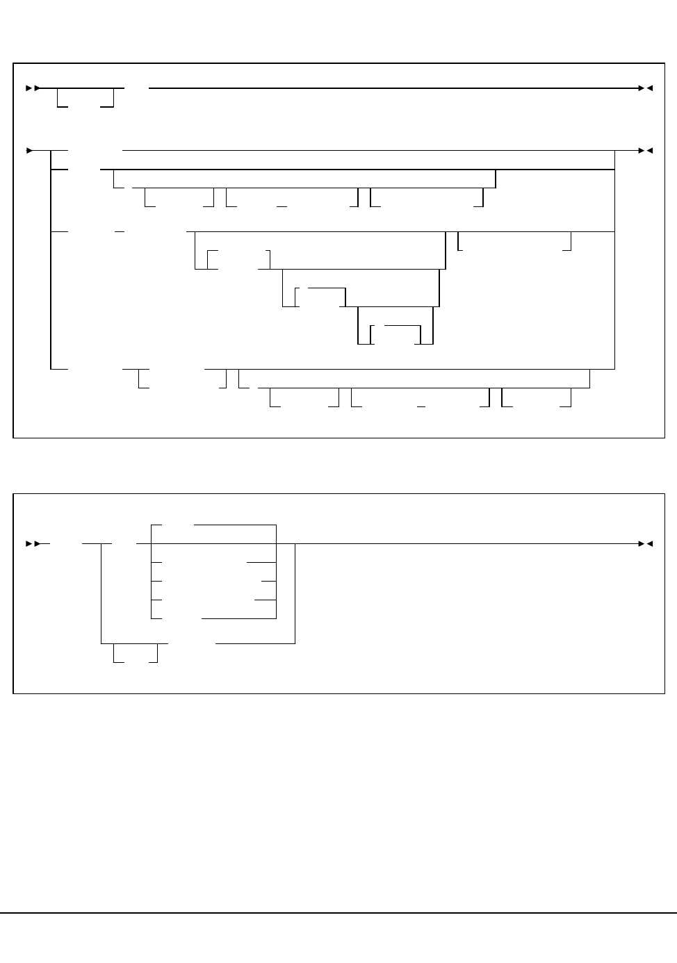
494 VM/HSC 6.0 System Programmer’s Guide
1st ed., 6/30/04 - 312579601
CMS Operator Commands
ACS EXEC
CMS HELP
EXEC
ACS
command
INIT
(
NOJOBs BREAK breakstr PARM=parmstr
SUBMIT jobfname
SLKJCL
ftype
*
fmode
U
class
(PARM=parmstr
UTILity
util-list
utility
(
NOSEND JOBName jobname NOEDIT
HELP ACS
MENU
scp-command
=diag-command
.hsc-command
topic
MSG
msgnum

Appendix B. CP Commands and DIAGNOSE Codes 495
1st ed., 6/30/04 - 312579601
Appendix B. CP Commands and DIAGNOSE Codes
Overview
This appendix lists all of the CP commands and programming services codes that may be
issued by the VM HSC. The VM HSC uses only privilege class G DIAGNOSE codes, and
with the exception of MSGNOH, uses only privilege class G commands. Refer to ‘‘Define
the ACS Service Machine’’ in the HSC Installation Guide for more information about
MSGNOH.
CP Commands
The following CP commands may be issued by the VM HSC:
CP Programming Services
The following DIAGNOSE codes may be issued by the HSC:
DIAGNOSE Code X’00’ Store extended-identification code.
DIAGNOSE Code X’08’ Virtual console function
DIAGNOSE Code X’0C’ Pseudo timer
DIAGNOSE Code X’14’ Input spool file manipulation.
DIAGNOSE Code X’20’ General I/O.
DIAGNOSE Code X’24’ Device type and features.
DIAGNOSE Code X’60’ Determine virtual machine storage size.
DIAGNOSE Code X’7C’ Logical device support facility.
DIAGNOSE Code X’94’ VMDUMP function.
DIAGNOSE Code X’BC’ Open spool file (not used in VM Release 4 or HPO 4.2).
*BLOCKIO
*MSG
CHANGE IPL IPL PURGE SMSG
CLOSE LOGOFF QUERY SPOOL
DEFINE MESSAGE RESET TAG
DETACH MSGNOH SCREEN TERMINAL
DISPLAY ORDER SET TRANSFER

496 VM/HSC 6.0 System Programmer’s Guide
1st ed., 6/30/04 - 312579601
IUCV
Communication vehicle for API and communication with Host to Host component.

Appendix C. Record Formats 497
1st ed., 6/30/04 - 312579601
Appendix C. Record Formats
Overview
This appendix provides the record formats for the HSC SMF, LOGREC, Volume Report,
and Batch API records. These records are mapped by SMP/E-distributed macros.
Each record format contains the following information:
• decimal representation
• hexadecimal representation
•type
•length
• label information
• description.
Some important points to remember when referencing record formats are:
•Types ‘‘Constant (CONST),’’ ‘‘Character Constant (CHAR CONST),’’
‘‘BITMAP,’’ and ‘‘Length (LENGTH)’’ contain values in the Decimal and
Hexadecimal columns.
•Type ‘‘AREA’’ contains offsets in the Decimal and Hexadecimal columns. The
Length is the length of an area. (An area defines an area of storage only.)
•Type ‘‘STRUCTURE’’ contains zeros in both the Decimal and Hexadecimal
columns and the Label column contains a DSECT name. The Length is blank.
• With Label ‘‘name (Rep count),’’ the Length is equal to the length of one element.
The total length of the entire field is found by multiplying the Length times the Rep
count.
• If the Label equals -RESERVED-, there is not a label for that particular field.
•Type ‘‘Offset’’ contains an offset in the Decimal and Hexadecimal columns and the
Length is always blank.

498 VM/HSC 6.0 System Programmer’s Guide
1st ed., 6/30/04 - 312579601
Table 30 provides a key to the SMF record format tables.
Mapping Macros for SMF Records
Mapping macros for SMF records are listed in Table 31 on page 499.
Mapping Macros for LOGREC Records
Mapping macros for LOGREC records are listed in Table 42 on page 525.
Mapping Macros for Volume Report and Batch API Records
Mapping macros for Volume Report and Batch API records are listed in Table 57 on page
562.
Mapping Macros for Batch API Records
Mapping macros for Batch API Records available only through the Batch API are listed in
Table 64 on page 593.
Table 30. Key to Record Format Tables
Dec Hex Type Length
values CONSTANT
CHAR CONST
BITMAP
LENGTH
offset
AREA length
0 (0) STRUCTURE blank
offset
CHARACTER
HEXSTRING
BITSTRING
SIGNED-FWORD
SIGNED-HWORD
SHORT-FLOAT
LONG-FLOAT
A-ADDR
Y-ADDR
S-ADDR
V-ADDR
PACKED-DEC
ZONED-DEC
EXTENDED FLOAT
length (length of one element)
offset
OFFSET blank

Appendix C. Record Formats 499
1st ed., 6/30/04 - 312579601
SMF Records
SMF Mapping Macros
Table 31. Mapping Macros for SMF Records
Macro Description
SLSDVAR Volume Attribute Record Data Length (within other SMF
records)
SLSSFHDR SMF Record Header Information
SLSSBLOS SMF LSM Operations Statistics
SLSSCAPJ SMF CAP Eject Record
SLSSCAPN SMF CAP Enter Record
SLSSVSTA SMF Vary Station Record
SLSSMLSM SMF Modify LSM Record
SLSSLSB SMF LMU ATHS Statistics Buffer
SLSSMF07 SMF Move Detail Record
SLSSMF08 SMF View Detail Record

500 VM/HSC 6.0 System Programmer’s Guide
1st ed., 6/30/04 - 312579601
SMF Record Formats
SLSDVAR
Cross Reference
Table 32. SLSDVAR Record Format
Dec Hex Type Length Label Description
SLSDVAR - Distributed Volume Attribute Record Length
FUNCTION:
Pass the HSC Volume Attribute Record Length(VARL) for other
Distributed HSC Macros to use as needed.
0 (0) HEXSTRING 40 SLSDVAR Volume Attribute Record
40 (28) LENGTH VARL Length of SLSDVAR(VAR)
Name Len Offset
Value
SLSDVAR 000040 00
VARL - 28

Appendix C. Record Formats 501
1st ed., 6/30/04 - 312579601
SLSSFHDR
Table 33. SLSSFHDR Record Format
Dec Hex Type Length Label Description
SLSSFHDR - SMF RECORD HEADER MAP
FUNCTION:
MAPS THE STANDARD SMF RECORD HEADER AS DEFINED IN THE IBM SMF
MANUAL (GC28-1153). IBM PROVIDES NO MAPPING MACRO. MAPS THE
ACHS EXTENSIONS TO THE HEADER.
SYMBOLICS:
&TYPE - USED TO SELECT A VALID SMF RECORD TYPE
1 - BLOS STATISTICS
2 - VARY STATION COMMAND
3 - MODIFY LSM COMMAND
4 - LMU READ STATISTICS
5 - CARTRIDGE EJECT
6 - CARTRIDGE ENTER
7 - MOVE DETAIL
8 - VIEW STATISTICS
9 - (VTCS) SUBSYSTEM CONFIGURATION CHANGE
--------------------------------------------------------------
THE FOLLOWING VTCS SUBTYPES DO NOT SUPPORT DSECT GENERATION
BY THIS SLSSFHDR.MACRO.
--------------------------------------------------------------
10 - (VTCS) SUBSYSTEM PERFORMANCE REQUEST
11 - (VTCS) CHANNEL INTERFACE PERFORMANCE REQUEST
12 - (VTCS) STATE SAVE
13 - (VTCS) VTV MOUNT REQUEST
14 - (VTCS) VTV DISMOUNT REQUEST
15 - (VTCS) VTV DELETE REQUEST
16 - (VTCS) RTD MOUNT REQUEST
17 - (VTCS) RTD DISMOUNT REQUEST
18 - (VTCS) VTV TO MVC REQUEST
19 - (VTCS) RECALL VTV FROM MVC REQUEST
20 - (VTCS) RTD PERFORMANCE REQUEST
21 - (VTCS) RTD VARY REQUEST
22 - (VTCS) HOST INITIATED MIM EVENT
23 - (VTCS) CHANGE OF SCRATCH DELETION POLICY
24 - (VTCS) MVC MEDIA DISCONTINUED USAGE EVENT
25 - (VTCS) MVC USAGE RECORDING
26 - (VTCS) VTV MOVEMENT
27 - (VTCS) VTV SCRATCH EVENT
28 - (VTCS) REPLICATE VTV TO CLUSTERED VTSS REQUEST
0 (0) STRUCTURE SLSSFHDR RECORD HEADER
0 (0) SIGNED-HWORD 2 OSHDRECL RECORD LENGTH
2 (2) SIGNED-HWORD 2 OSHDDESC SEGMENT DESCRIPTOR
4 (4) BITSTRING 1 OSHDFLAG SYSTEM INDICATOR FLAGS
.1.. .... X’40’ OSHDSTV Subtypes are valid
5 (5) HEXSTRING 1 OSHDRCTY SMF RECORD TYPE
6 (6) HEXSTRING 4 OSHDTIME TIME RECORD WAS WRITTEN. BINARY
HUNDREDTHS OF SECONDS.
10 (A) HEXSTRING 4 OSHDDATE DATE RECORD WAS WRITTEN. FORMAT:
X’0CYYDDDF’. THE DATE/TIME FIELDS
ARE SET BY SLSSWSMF MODULE.
14 (E) CHARACTER 4 OSHDSID SYSTEM ID

502 VM/HSC 6.0 System Programmer’s Guide
1st ed., 6/30/04 - 312579601
18 (12) CHARACTER 4 OSHDSSID SUBSYSTEM ID
22 (16) SIGNED-HWORD 2 OSHDRSTY RECORD SUBTYPE. If adding new record
subtype(s), change field OSHDMAXS and add
an entry in the HSSUBS table of SLUPERF.
Then reassemble modules SLSOOSMF,
SLSOWSMF, and SLUPERF.
1 (01) CONST OSHDBLOS BLOS STATISTICS SUBTYPE
2 (02) CONST OSHDVSTA VARY STATION COMMAND SUBTYPE
3 (03) CONST OSHDMLSM MODIFY LSM COMMAND SUBTYPE
4 (04) CONST OSHDLRST LMU READ STATISTICS SUBTYPE
5 (05) CONST OSHDEJCT CARTRIDGE EJECT SUBTYPE
6 (06) CONST OSHDENTR CARTRIDGE ENTER SUBTYPE
7 (07) CONST OSHDRC07 MOVE DETAIL SUBTYPE
8 (08) CONST OSHDVIEW VIEW STATISTICS
9 (09) CONST OSHDLS09 (VTCS) Subsystem Configuration Change
SLSSFHDR.mac will NOT generate DSECTS for the following
VTCS SMF SUBTYPEs.
10 (0A) CONST OSHDVT10 (VTCS) Subsystem Performance Request
11 (0B) CONST OSHDVT11 (VTCS) Channel Interface Performance Rqst
12 (0C) CONST OSHDVT12 (VTCS) State Save
13 (0D) CONST OSHDVT13 (VTCS) VTV MOUNT Request
14 (0E) CONST OSHDVT14 (VTCS) VTV DISMOUNT Request
15 (0F) CONST OSHDVT15 (VTCS) VTV DELETE Request
16 (10) CONST OSHDVT16 (VTCS) RTD MOUNT Request
17 (11) CONST OSHDVT17 (VTCS) RTD DISMOUNT Request
18 (12) CONST OSHDVT18 (VTCS) VTV to MVC Request
19 (13) CONST OSHDVT19 (VTCS) RECALL VTV from MVC Request
20 (14) CONST OSHDVT20 (VTCS) RTD PERFORMANCE Request
21 (15) CONST OSHDVT21 (VTCS) RTD VARY Request
22 (16) CONST OSHDVT22 (VTCS) HOST Initiated MIM Event
23 (17) CONST OSHDVT23 (VTCS) CHANGE of SCRATCH DELETION
Policy
24 (18) CONST OSHDVT24 (VTCS) MVC Media DISCONTINUED
USAGE Event
25 (19) CONST OSHDVT25 (VTCS) MVC USAGE Recording
26 (1A) CONST OSHDVT26 (VTCS) VTV MOVEMENT
Table 33. SLSSFHDR Record Format (Continued)
Dec Hex Type Length Label Description

Appendix C. Record Formats 503
1st ed., 6/30/04 - 312579601
27 (1B) CONST OSHDVT27 (VTCS) VTV SCRATCH Event
28 (1C) CONST OSHDVT28 (VTCS) REPLICATE VTV->CLUSTERED
VTSS Rqst
28 (1C) CONST OSHDMAXS MAXIMUM RECORD SUBTYPE VALUE
24 (18) LENGTH OSHDL LENGTH OF FIXED PORTION OF OSHDR
24 (18) OFFSET SLSSTYPE DEFINE EACH SMF SUBTYPE
Table 33. SLSSFHDR Record Format (Continued)
Dec Hex Type Length Label Description

504 VM/HSC 6.0 System Programmer’s Guide
1st ed., 6/30/04 - 312579601
Cross Reference
Name Len
Offset
Value
OSHDBLOS - 01
OSHDDATE 000004 0A
OSHDDESC 000002 02
OSHDEJCT - 05
OSHDENTR - 06
OSHDFLAG 000001 04
OSHDL - 18
OSHDLRST - 04
OSHDMAXS - 1C
OSHDMLSM - 03
OSHDRCTY 000001 05
OSHDRC07 - 07
OSHDRECL 000002 00
OSHDRSTY 000002 16
OSHDSID 000004 0E
OSHDSSID 000004 12
OSHDSTV - 40
OSHDTIME 000004 06
OSHDVIEW - 08
OSHDVSTA - 02
OSHDVT09 - 09
OSHDVT10 - 0A
OSHDVT11 - 0B
OSHDVT12 - 0C
OSHDVT13 - 0D
OSHDVT14 - 0E
OSHDVT15 - 0F
OSHDVT16 - 10
OSHDVT17 - 11
OSHDVT18 - 12
OSHDVT19 - 13

Appendix C. Record Formats 505
1st ed., 6/30/04 - 312579601
OSHDVT20 - 14
OSHDVT21 - 15
OSHDVT22 - 16
OSHDVT23 - 17
OSHDVT24 - 18
OSHDVT25 - 19
OSHDVT26 - 1A
OSHDVT27 - 1B
OSHDVT28 - 1C
SLSSTYPE - 18
Name Len
Offset
Value

506 VM/HSC 6.0 System Programmer’s Guide
1st ed., 6/30/04 - 312579601
SLSSBLOS
Table 34. SLSSBLOS Record Format
Dec Hex Type Length Label Description
SLSSBLOS - LSM OPERATIONS STATISTICS
FUNCTION: CONTAINS PERFORMANCE STATISTICS FOR THE LSM. THE SAME
STRUCTURE IS USED TO CREATE THE SMF PERFORMANCE RECORD,
HOWEVER THE CONTROL BLOCK HEADER IS ELIMINATED, AND ONLY
THE FIXED AND MULTIPLE SECTIONS GENERATED. THE FIXED
SECTION OF THE RECORD IS OSHDL OFF THE BEGINNING OF THE
SMF RECORD. THE MULTIPLE SECTION IS BLOSLSSL OFF THE
FIXED SECTION, AND THE FIELD BLOSKNT IN THE SMF RECORD
DEFINES THE NUMBER OF MULTIPLE SECTIONS TO FOLLOW
SYMBOLICS:
&DSECT - DSECT OR CONTINUATION OF DATA AREA.
YES - PRODUCE A DSECT LISTING
NO - NO DSECT
0 (0) AREA 2 SLSSBLOS LSM OPERATIONS STATISTICS DATA
AREA
START OF SMF FIXED PORTION
0 (0) SIGNED-HWORD 2 BLOSKNT COUNT OF BLOS DATA AREAS TO
FOLLOW
ZERO IN “IN MEMORY” VERSION.
2 (02) LENGTH BLOSLSSL LENGTH OF FIXED SMF PORTION.
START OF SMF MULTIPLE SECTION.
2 (2) A-ADDR 1 BLOSTYP0 TYPE OF STATISTIC FLAGS
1... .... X’80’ BLOSMSS MOUNT SCRATCH
.1.. .... X’40’ BLOSMNS MOUNT NON-SCRATCH
..1. .... X’20’ BLOSDSS DISMOUNT SCRATCH
...1 .... X’10’ BLOSDNS DISMOUNT NON-SCRATCH
.... 1... X’08’ BLOSSWS SWAP
.... .1.. X’04’ BLOSMOV MOVE
.... ..1. X’02’ BLOSNTR ENTER
.... ...1 X’01’ BLOSEJT EJECT
3 (3) A-ADDR 1 -RESERVED- *** RESERVED
4 (4) SIGNED-FWORD 4 BLOSSOPC SAME LSM OPERATION COUNT
8 (8) SIGNED-FWORD 4 BLOSSTIM SAME LSM ELAPSED TIME. BINARY
INTEGER COUNT, IN MILLISECONDS
- THOUSANDTHS OF SECONDS.
12 (C) SIGNED-FWORD 4 BLOSDOPC DIFFERENT LSM OPERATION
COUNT

Appendix C. Record Formats 507
1st ed., 6/30/04 - 312579601
Cross Reference
16 (10) SIGNED-FWORD 4 BLOSDTIM DIFFERENT LSM ELAPSED TIME
20 (14) SIGNED-FWORD 4 BLOSPTRU PASSTHRU COUNT
22 (16) LENGTH BLOSVL LENGTH OF DATA SECTION
20 (14) LENGTH BLOSVL1 LENGTH OF COUNTER SECTION
24 (18) LENGTH BLOSL BLOS LENGTH
Name Len
Offset
Value
BLOSDNS - 10
BLOSDOPC 000004 0C
BLOSDSS - 20
BLOSDTIM 000004 10
BLOSEJT - 01
BLOSKNT 000002 00
BLOSL - 18
BLOSLSSL - 02
BLOSMNS - 40
BLOSMOV - 04
BLOSMSS - 80
BLOSNTR - 02
BLOSPTRU 000004 14
BLOSSOPC 000004 04
BLOSSTIM 000004 08
BLOSSWS - 08
BLOSTYP0 000001 02
BLOSVL - 16
BLOSVL1 - 14
SLSSBLOS 000002 00
Table 34. SLSSBLOS Record Format (Continued)
Dec Hex Type Length Label Description

508 VM/HSC 6.0 System Programmer’s Guide
1st ed., 6/30/04 - 312579601
SLSSCAPJ
Cross Reference
Table 35. SLSSCAPJ Record Format
Dec Hex Type Len Label Description
SLSSCAPJ - CAP EJECT SMF RECORD
FUNCTION:
USED TO HOLD INFORMATION PASSED TO THE ALS SMF WRITER SERVICE ROUTINE FOR
THE CARTRIDGE EJECT EVENT.
SYMBOLICS:
&DSECT - DSECT OR CONTINUATION OF DATA AREA
YES - PRODUCE A DSECT LISTING
NO - NO DSECT
6 (6) AREA 2 SLSSCAPJ CAP EJECT SMF RECORD SUBTYPE
6 (6) HEXSTRING 6 CJSMFDES DESTINATION CAP LOCATION
12 (C) HEXSTRING 40 CJSMFVAR VOL ATTRIBUTE RECORD FOR
CARTRIDGE
46 (2E) LENGTH CJSMFL LENGTH OF EJECT RECORD
Name Len
Offset
Value
CJSMFDES 000006 06
CJSMFL - 2E
CJSMFVAR 000040 0C
SLSSCAPJ 000002 06

Appendix C. Record Formats 509
1st ed., 6/30/04 - 312579601
SLSSCAPN
Cross Reference
Table 36. SLSSCAPN Record Format
Dec Hex Type Length Label Description
SLSSCAPN - CAP ENTER SMF RECORD
FUNCTION:
USED TO HOLD INFORMATION PASSED TO THE ALS SMF WRITER
SERVICE ROUTINE FOR THE CARTRIDGE ENTER EVENT.
SYMBOLICS:
&DSECT - DSECT OR CONTINUATION OF DATA AREA.
YES - PRODUCE A DSECT LISTING
NO - NO DSECT
6 (6) AREA 2 SLSSCAPN CAP ENTER SMF RECORD SUBTYPE
6 (6) HEXSTRING 6 CNSMFSRC SOURCE CAP LOCATION
12 (C) HEXSTRING 40 CNSMFVAR VOL ATTRIBUTE RECORD FOR
CARTRIDGE
46 (2E) LENGTH CNSMFL LENGTH OF EJECT RECORD
Name Len
Offset
Value
CNSMFL - 2E
CNSMFSRC 000006 06
CNSMFVAR 000040 0C
SLSSCAPN 000002 06

510 VM/HSC 6.0 System Programmer’s Guide
1st ed., 6/30/04 - 312579601
SLSSVSTA
Table 37. SLSSVSTA Record Format
Dec Hex Type Length Label Description
SLSSVSTA - VARY STATION SMF RECORD SUBTYPE MAP
FUNCTION:
CONTAINS A RECORD OF SUCCESSFUL SUBSYSTEM VARY COMMANDS.
SYMBOLICS: &DSECT - DSECT OR CONTINUATION OF DATA AREA.
YES - PRODUCE A DSECT LISTING
NO - NO DSECT
0 (0) AREA 2 SLSSVSTA VARY STATION SMF RECORD
SUBTYPE
0 (0) SIGNED-FWORD 4 SVSTFLAG FLAGS
0 (0) A-ADDR 1 SVSTFLG0 TYPE OF STATISTIC FLAGS
1... .... X’80’ SVSTVON VARY ON
.1.. .... X’40’ SVSTVOF VARY OFF
..1. .... X’20’ SVSTFOR VARY FORCE
...1 .... X’10’ SVSTACS SET ACS MODE
.... 1... X’08’ SVSTSTBY STATION ON STANDBY
.... .1.. X’04’ SVSTVACS ACS VARY REQUESTED
1 (1) A-ADDR 3 -RESERVED- *** RESERVED
FOR STATION VARY:
4 (4) HEXSTRING 2 SVSTATID STATION ID
6 (6) HEXSTRING 2 SVSTUNID MVS UNIT NUMBER
FOR ACS VARY:
4 (4) HEXSTRING 1 SVSTACID ACS ID
5 (5) A-ADDR 3 -RESERVED- *** UNUSED FOR VARY ACS
8 (08) LENGTH SVSTL LENGTH OF DATA SECTION

Appendix C. Record Formats 511
1st ed., 6/30/04 - 312579601
Cross Reference
Name Len
Offset
Value
SLSSVSTA 000002 00
SVSTACID 000001 04
SVSTACS - 10
SVSTATID 000002 04
SVSTFLAG 000004 00
SVSTFLG0 000001 00
SVSTFOR - 20
SVSTL - 08
SVSTSTBY - 08
SVSTUNID 000002 06
SVSTVACS - 04
SVSTVOF - 40
SVSTVON - 80

512 VM/HSC 6.0 System Programmer’s Guide
1st ed., 6/30/04 - 312579601
SLSSMLSM
Cross Reference
Table 38. SLSSMLSM Record Format
Dec Hex Type Length Label Description
SLSSMLSM - MODIFY LSM SMF RECORD SUBTYPE MAP
FUNCTION:
CONTAINS A RECORD OF SUCCESSFUL SUBSYSTEM MODIFY COMMANDS.
SYMBOLICS:
&DSECT - DSECT OR CONTINUATION OF DATA AREA.
YES - PRODUCE A DSECT LISTING
NO - NO DSECT
0 (0) AREA 2 SLSSMLSM MODIFY LSM SMF RECORD
SUBTYPE
0 (0) SIGNED-FWORD 4 SMLSFLAG FLAGS
0 (0) A-ADDR 1 SMLSFLG0 TYPE OF STATISTIC FLAGS
1... .... X’80’ SMLSVON MODIFY ON
.1.. .... X’40’ SMLSVOF MODIFY OFF
..1. .... X’20’ SMLSFOR MODIFY FORCE
1 (1) A-ADDR 3 -RESERVED- RESERVED
4 (4) HEXSTRING 2 SMLSATID LSM ID
6 (06) LENGTH SMLSL LENGTH OF DATA SECTION
Name Len
Offset
Value
SLSSMLSM 000002 00
SMLSATID 000002 04
SMLSFLAG 000004 00
SMLSFLG0 000001 00
SMLSFOR - 20
SMLSL - 06
SMLSVOF - 40
SMLSVON - 80

Appendix C. Record Formats 513
1st ed., 6/30/04 - 312579601
SLSSLSB
Table 39. SLSSLSB Record Format
Dec Hex Type Length Label Description
SLSSLSB - LMU STATISTICS BUFFER DATA BLOCK
FUNCTION:
THE CALLER OF THE SLSLRSTA FUNCTION SUPPLIES THE ADDRESS OF
A DATA BUFFER TO BE FILLED IN WITH THE RESPONSE DATA FROM
AN LMU READ STATISTICS REQUEST. THE DATA AREA CONTAINS 16
ENTRIES, ONE FOR EACH LSM CONFIGURED TO THE LMU.
INFORMATION SUPPLIED ABOUT EACH LSM INCLUDES:
1) LSM ARM UTILIZATION PERCENTAGE.
2) LSM NUMBER MASTER PASSTHRU PORT ONE
IS CONNECTED TO.
3) LSM NUMBER MASTER PASSTHRU PORT TWO
IS CONNECTED TO.
SYMBOLICS:
&DSECT - DSECT OR CONTINUATION OF DATA AREA.
YES - PRODUCE A DSECT LISTING
NO - NO DSECT
0 (0) AREA 2 SLSSLSB LMU ATHS STATISTICS BUFFER
0 (0) HEXSTRING 2 LSBMON MONTH
2 (2) HEXSTRING 2 LSBDAY DAY
4 (4) HEXSTRING 2 LSBHR HOUR
6 (6) HEXSTRING 2 LSBMIN MINUTE
8 (8) HEXSTRING 2 LSBSEC SECOND
10 (A) HEXSTRING 20 LSBLSBE(16) ONE FOR EACH LSM
330 (14A) HEXSTRING 1 LSBACS ACS ID RANGE IS X’00’ TO X’FF’
331 (14B) HEXSTRING 3 -RESERVED- *** RESERVED
336 (150) SIGNED-FWORD 4 -RESERVED- *** RESERVED
340 (154) LENGTH LSBL SIZE OF LSB
DSECT DESCRIBING EACH LSM STATISTICS BUFFER
0 (0) STRUCTURE SLSSLSBE STATISTICS BUFFER.
0 (0) SIGNED-FWORD 4 LSBEARMU ARM UTILIZATION PERCENTAGE.
4 (4) SIGNED-FWORD 4 LSBECNT1 PASSTHRU PORT 1 USAGE COUNT.
8 (8) SIGNED-FWORD 4 LSBECNT2 PASSTHRU PORT 2 USAGE COUNT.
12 (C) HEXSTRING 1 LSBECON1 PASSTHRU PORT 1 CONNECTIVITY.
12 (C) HEXSTRING 1 LSBECON2 PASSTHRU PORT 2 CONNECTIVITY.

514 VM/HSC 6.0 System Programmer’s Guide
1st ed., 6/30/04 - 312579601
Cross Reference
LSBECON1 AND LSBECON2 HAVE THE FOLLOWING MAPPING:
BYTE 0 - RESERVED
BYTE 1 - ACSID
BYTE 2 - SLAVE LSMID
BYTE 3 - RESERVED
BYTE 4 - RESERVED
BYTE 5 - RESERVED
12 (C) SIGNED-FWORD 4 -RESERVED-(2) *** RESERVED
20 (14) LENGTH LSBEL SIZE OF LSBE.
Name Len
Offset
Value
LSBACS 000001 14A
LSBDAY 000002 02
LSBEARMU 000004 00
LSBECNT1 000004 04
LSBECNT2 000004 08
LSBECON1 000001 0C
LSBECON2 000001 0C
LSBEL - 14
LSBHR 000002 04
LSBL - 154
LSB
LSBE 000020 0A
LSBMIN 000002 06
LSBMON 000002 00
LSBSEC 000002 08
SLSSLSB 000002 00
Table 39. SLSSLSB Record Format (Continued)
Dec Hex Type Length Label Description

Appendix C. Record Formats 515
1st ed., 6/30/04 - 312579601
SLSSMF07
Table 40. SLSSMF07 Record Format
Dec Hex Type Length Label Description
DSECT: SLSSMF07 - HSC RECORD TYPE 7 MAPPING MACRO
FUNCTION:
MAPS THE SUBTYPE 7 SMF RECORD PRODUCED BY THE HSC. THIS IS
PRODUCED FOR EACH SUCCESSFUL MOVE INITIATED BY THE HSC.
THESE RECORDS WERE ORIGINALLY DESIGNED TO PROVIDE OUR FIELD AND MARKETING STAFFS
WITH STATISTICAL CARTRIDGE MOVEMENT, LMU TIMING, AND ROBOTICS TIMING INFORMATION.
THESE RECORDS REPORT MOVEMENT SOURCE, DESTINATION, LMU TIMES, AND ROBOTICS TIMES. THESE
RECORDS ALSO CONTAIN VALUABLE SYSTEM ID AND JOB INFORMATION.
USAGE TIPS:
TO FIND ENTER ACTIVITY WITH THE SLSSMF07 RECORDS:
• FIND ALL SLSSMF07 MOVE DETAIL RECORDS WITH A SOURCE IDENTIFIER (SMF07SRI) = “CAP”(SMF07SCP).
• YOU CAN DETERMINE THE LIBRARY CARTRIDGE MOVEMENT TYPE THAT INITIATED THE ENTER
BY CHECKING SMF07TYP.
TO FIND EJECT ACTIVITY WITHIN THE SLSSMF07 RECORDS:
• FIND ALL SLSSMF07 MOVE DETAIL RECORDS WITH A DESTINATION IDENTIFIER(SMF07DEI) =
“CAP”(SMF07TCP).
• YOU CAN DETERMINE THE LIBRARY CARTRIDGE MOVEMENT TYPE THAT INITIATED THE EJECT BY
CHECKING SMF07TYP.
0 (0) AREA 1 SLSSMF07 MOVE DETAIL SMF RECORD
SUBTYPE
THIS DSECT MAPS THE SUBTYPE 7 RECORD PRODUCED BY THE HSC FOR EACH SUCCESSFUL MOVE IF SUBTYPE
7 RECORDING IS ENABLED.
0 (0) BITSTRING 1 SMF07TYP TYPE OF RECORD
1... .... X’80’ SMF07MSS MOUNT SCRATCH
.1.. .... X’40’ SMF07MNS MOUNT NON-SCRATCH
..1. .... X’20’ SMF07DSS DISMOUNT SCRATCH
...1 .... X’10’ SMF07DNS DISMOUNT NON-SCRATCH
.... 1... X’08’ SMF07SWS SWAP
.... .1.. X’04’ SMF07MOV MOVE
.... ..1. X’02’ SMF07NTR ENTER
.... ...1 X’01’ SMF07EJT EJECT
1 (1) BITSTRING 1 SMF07RQS REQUESTOR IDENTIFIER
.... .... X’00’ SMF07UNK UNKNOWN
.... ...1 X’01’ SMF07HSC HSC INITIATED (E.G. AUTOMATIC
CLEANING OF A DRIVE)
.... ..1. X’02’ SMF07JOB JOB PROCESSING INITIATED
.... ..11 X’03’ SMF07UTL HSC UTILITY INITIATED
.... .1.. X’04’ SMF07PRG HSC PROGRAMMATIC INTERFACE

516 VM/HSC 6.0 System Programmer’s Guide
1st ed., 6/30/04 - 312579601
.... .1.1 X’05’ SMF07OPR HSC OPERATOR COMMAND
INITIATED
.... .11. X’06’ SMF07TMI VM TMI INTERFACE
2 (2) BITSTRING 1 SMF07FLG FLAG BYTE
1... .... X’80’ SMF07DSV SMF07DRS CONTAINS A DRIVE
DEVICE NUM
.1.. .... X’40’ SMF07DTV SMF07DRT CONTAINS A DRIVE
DEVICE NUM
..1. .... X’20’ SMF07CNV SMF07CON CONTAINS VALID DATA
...1 .... X’10’ SMF07LMD LMU DATA IS AVAILABLE
.... 1... X’08’ SMF07PRF PERFORMANCE SIGNIFICANTLY
IMPACTED BY LMU RETRY
3 (3) HEXSTRING 4 SMF07TTM TIME IN HUNDREDTHS THE
REQUEST WAS WAS RECEIVED BY
THE HSC. ONLY
7 (7) HEXSTRING 4 SMF07TDT DATE THE REQUEST WAS RECEIVED
BY THE HSC (0CYYDDDF)
11 (B) HEXSTRING 4 SMF07LTM TIME IN HUNDREDTHS THE
REQUEST WAS WAS RECEIVED BY
THE LMU SERVER
15 (F) HEXSTRING 4 SMF07LDT DATE THE REQUEST WAS RECEIVED
BY THE LMU SERVER
19 (13) HEXSTRING 4 SMF07NRD INTERVAL IN HUNDREDTHS THE
REQUEST WAS QUEUED BECAUSE A
LSM WAS NOT READY.
23 (17) HEXSTRING 4 SMF07CPO INTERVAL IN HUNDREDTHS OF A
SECOND THE REQUEST WAS
DELAYED DUE TO CAP
OPERATIONS. THIS INCLUDES THE
WAIT TIME FOR THE DOOR TO
OPEN, CLOSE THE DOOR, DOOR,
FILL OR EMPTY THE CAP, CLOSE
THE DOOR, AND SCAN THE CAP.
HEX ‘FFFFFFFF’ INDICATES
COUNTER OVERFLOW
Table 40. SLSSMF07 Record Format (Continued)
Dec Hex Type Length Label Description

Appendix C. Record Formats 517
1st ed., 6/30/04 - 312579601
27 (1B) CHARACTER 8 SMF07US1 THIS SHOULD ALWAYS ONLY
CONTAIN DISPLAYABLE EBCDIC
(INC BLANKS). JOBNAME IF REQ
FROM JOB PROCESSING, HSC
UTILITY, OR HSC PROGRAMATIC
INTERFACE, OR HSC INITIATED.
‘CONSOLE’ IF INITIATED BY THE
OPERATOR VIRTUAL MACHINE
NAME THE IUCV RECEIVED FROM
(VM TMS INTERFACE)
35 (23) CHARACTER 8 SMF07US2 THIS SHOULD ALWAYS ONLY
CONTAIN DISPLAYABLE EBCDIC
(INC BLANKS). SMFID (JES2) IF REQ
FROM JOB PROCESSING, HSC
UTILITY, OR HSC MAIN PROCESSOR
NAME (JES3). IF REQ FROM JOB
PROCESSING, HSC UTILITY, OR HSC.
THE CONSOLEID IN DISPLAYABLE
FORMAT IF INITIATED BY THE
OPERATOR NODE NAME (VM TMS
INTERFACE)
43 (2B) HEXSTRING 4 SMF07CON CONSOLEID IF INITIATED BY THE
OPERATOR
47 (2F) CHARACTER 1 SMF07LBL LABEL MODIFIER
‘1’ (F1) CHAR CONST SMF07MVV VERIFY LABEL VOLSER
‘2’ (F2) CHAR CONST SMF07MVU VERIFY UNLABELED CARTRIDGE
‘3’ (F3) CHAR CONST SMF07MBV BYPASS LABEL VERIFICATION
‘4’ (F4) CHAR CONST SMF07MRC RECOVERY CARTRIDGE
‘5’ (F5) CHAR CONST SMF07VMT VERIFY MEDIA AND BYPASS
VOLSER
‘6’ (F6) CHAR CONST SMF07VMV VERIFY MEDIA AND VOLSER
‘7’ (F7) CHAR CONST SMF07VMU VERIFY MEDIA AND UNREADABLE
LBL
48 (30) CHARACTER 6 SMF07VOL VOLSER BEING MOVED NOTE -
ROW AND COLUMN COORDINATES
HAVE DIFFERENT MEANINGS FOR
CELLS, CAPS, AND DRIVES.
54 (36) CHARACTER 1 SMF07SF1 SOURCE MODIFIER
‘1’ (F1) CHAR CONST SMF07SFN NORMAL
‘2’ (F2) CHAR CONST SMF07SFI ONLY SMF07SAC AND SMF07SLS
VA L I D
55 (37) CHARACTER 1 SMF07SRI SOURCE IDENTIFIER
Table 40. SLSSMF07 Record Format (Continued)
Dec Hex Type Length Label Description

518 VM/HSC 6.0 System Programmer’s Guide
1st ed., 6/30/04 - 312579601
‘1’ (F1) CHAR CONST SMF07SCE CELL
‘2’ (F2) CHAR CONST SMF07SCP CAP
‘3’ (F3) CHAR CONST SMF07SDR DRIVE
56 (38) HEXSTRING 1 SMF07SAC SOURCE ACS
57 (39) HEXSTRING 1 SMF07SLS SOURCE LSM
58 (3A) HEXSTRING 1 SMF07SPN SOURCE PANEL
59 (3B) HEXSTRING 1 SMF07SRO SOURCE ROW
60 (3C) HEXSTRING 1 SMF07SCO SOURCE COLUMN
61 (3D) CHARACTER 1 SMF07DEI DESTINATION IDENTIFIER
‘1’ (F1) CHAR CONST SMF07TCE CELL
‘2’ (F2) CHAR CONST SMF07TCP CAP
‘3’ (F3) CHAR CONST SMF07TDR DRIVE
‘5’ (F5) CHAR CONST SMF07TDW DRIVE (WRITE PROTECT)
62 (3E) HEXSTRING 1 SMF07TAC DESTINATION ACS
63 (3F) HEXSTRING 1 SMF07TLS DESTINATION LSM
64 (40) HEXSTRING 1 SMF07TPN DESTINATION PANEL
65 (41) HEXSTRING 1 SMF07TRO DESTINATION ROW
66 (42) HEXSTRING 1 SMF07TCO DESTINATION COLUMN
67 (43) HEXSTRING 2 SMF07DRS SOURCE DRIVE DEVICE NUMBER
INVOLVED WITH THE REQUEST.
VALID ONLY IF SMF07DSV IS ON.
69 (45) HEXSTRING 2 SMF07DRT DESTINATION DRIVE DEVICE
NUMBER INVOLVED WITH THE
REQUEST. VALID ONLY IF
SMF07DTV IS ON.
71 (47) HEXSTRING 4 SMF07STM TIME IN HUNDREDTHS THE
REQUEST WAS SENT TO THE LMU
75 (4B) HEXSTRING 4 SMF07SDT DATE THE REQUEST WAS SENT TO
THE LMU IN THE FORM 0CYYDDF.
79 (4F) HEXSTRING 4 SMF07ETM TIME IN HUNDREDTHS THE LMU
INDICATED THE REQUEST WAS
COMPLETE
83 (53) HEXSTRING 4 SMF07EDT DATE THE LMU INDICATED THE
REQUEST WAS COMPLETE.
87 (57) BITSTRING 1 SMF07TNM NUMBER OF LSMS USED
Table 40. SLSSMF07 Record Format (Continued)
Dec Hex Type Length Label Description

Appendix C. Record Formats 519
1st ed., 6/30/04 - 312579601
88 (58) LENGTH SMF07SL LENGTH OF NON-LMU PORTION OF
SUBRECORD
THIS MAPS THE DATA RETURNED BY THE LMU. IT IS ONLY AVAILABLE IF SMF07LMD IS ON. NOTE THAT THE LMU
TIMES ARE ONLY VALID TO A TENTH OF A SECOND. THE HSC CONVERTS THE TIMES TO HUNDREDTHS TO BE
CONSISTENT WITH OTHER TIMES.
88 (58) HEXSTRING 4 SMF07LTO INTERVAL IN HUNDREDTHS OF A
SECOND THE LMU HAD THE
REQUEST. HEX ‘FFFFFFFF’
INDICATES LMU COUNTER
OVERFLOW
92 (5C) HEXSTRING 4 SMF07DWT INTERVAL IN HUNDREDTHS OF A
SECOND OF DRIVE WAIT TIME. HEX
‘FFFFFFFF’ INDICATES LMU
COUNTER OVERFLOW
96 (60) HEXSTRING 4 SMF07DRO INTERVAL IN HUNDREDTHS OF
DESTINATION LSM ROBOTICS TIME
HEX ‘FFFFFFFF’ INDICATES LMU
COUNTER OVERFLOW
100 (64) HEXSTRING 4 SMF07DRQ INTERVAL IN HUNDREDTHS OF
DESTINATION LSM ROBOTICS
QUEUE TIME. HEX ‘FFFFFFFF’
INDICATES LMU COUNTER
OVERFLOW
104 (68) HEXSTRING 4 SMF07ORO INTERVAL IN HUNDREDTHS OF ALL
OTHER LSM ROBOTICS TIME HEX
‘FFFFFFFF’ INDICATES LMU
COUNTER OVERFLOW
108 (6C) HEXSTRING 4 SMF07ORQ INTERVAL IN HUNDREDTHS OF ALL
OTHER LSM ROBOTICS QUEUE
TIME. HEX ‘FFFFFFFF’ INDICATES
LMU COUNTER OVERFLOW
112 (70) HEXSTRING 4 SMF07PRO INTERVAL IN HUNDREDTHS OF
PASSTHRU ROBOTICS TIME HEX
‘FFFFFFFF’ INDICATES LMU
COUNTER OVERFLOW
116 (74) HEXSTRING 4 SMF07PRQ INTERVAL IN HUNDREDTHS OF ALL
PASSTHRU ROBOTICS QUEUE TIME.
HEX ‘FFFFFFFF’ INDICATES LMU
COUNTER OVERFLOW
120 (78) LENGTH SMF07L LENGTH OF FIXED PORTION OF
SUBRECORD
Table 40. SLSSMF07 Record Format (Continued)
Dec Hex Type Length Label Description

520 VM/HSC 6.0 System Programmer’s Guide
1st ed., 6/30/04 - 312579601
Cross Reference
Name Len
Offset
Value
SLSSMF07 000001 00
SMF07CNV - 20
SMF07CON 000004 2B
SMF07CPO 000004 17
SMF07DEI 000001 3D
SMF07DNS - 10
SMF07DRO 000004 60
SMF07DRQ 000004 64
SMF07DRS 000002 43
SMF07DRT 000002 45
SMF07DSS - 20
SMF07DSV - 80
SMF07DTV - 40
SMF07DWT 000004 5C
SMF07EDT 000004 53
SMF07EJT - 01
SMF07ETM 000004 4F
SMF07FLG 000001 02
SMF07HSC - 01
SMF07JOB - 02
SMF07L - 78
SMF07LBL 000001 2F
SMF07LDT 000004 0F
SMF07LMD - 10
SMF07LTM 000004 0B
SMF07LTO 000004 58
SMF07MBV - ‘CVAL’
SMF07MNS - 40
SMF07MOV - 04
SMF07MRC - ‘CVAL’
SMF07MSS - 80

Appendix C. Record Formats 521
1st ed., 6/30/04 - 312579601
SMF07MVU - ‘CVAL’
SMF07MVV - ‘CVAL’
SMF07NRD 000004 13
SMF07NTR - 02
SMF07OPR - 05
SMF07ORO 000004 68
SMF07ORQ 000004 6C
SMF07PRF - 08
SMF07PRG - 04
SMF07PRO 000004 70
SMF07PRQ 000004 74
SMF07RQS 000001 01
SMF07SAC 000001 38
SMF07SCE - ‘CVAL’
SMF07SCO 000001 3C
SMF07SCP - ‘CVAL’
SMF07SDR - ‘CVAL’
SMF07SDT 000004 4B
SMF07SFI - ‘CVAL’
SMF07SFN - ‘CVAL’
SMF07SF1 000001 36
SMF07SL - 58
SMF07SLS 000001 39
SMF07SPN 000001 3A
SMF07SRI 000001 37
SMF07SRO 000001 3B
SMF07STM 000004 47
SMF07SWS - 08
SMF07TAC 000001 3E
SMF07TCE - ‘CVAL’
SMF07TCO 000001 42
SMF07TCP - ‘CVAL’
Name Len
Offset
Value

522 VM/HSC 6.0 System Programmer’s Guide
1st ed., 6/30/04 - 312579601
SMF07TDR - ‘CVAL’
SMF07TDT 000004 07
SMF07TDW - ‘CVAL’
SMF07TLS 000001 3F
SMF07TMI - 06
SMF07TNM 000001 57
SMF07TPN 000001 40
SMF07TRO 000001 41
SMF07TTM 000004 03
SMF07TYP 000001 00
SMF07UNK - 00
SMF07US1 000008 1B
SMF07US2 000008 23
SMF07UTL - 03
SMF07VMT - ‘CVAL’
SMF07VMU - ‘CVAL’
SMF07VMV - ‘CVAL’
SMF07VOL 000006 30
Name Len
Offset
Value

Appendix C. Record Formats 523
1st ed., 6/30/04 - 312579601
SLSSMF08
Table 41. SLSSMF08 Record Format
Dec Hex Type Length Label Description
SLSSMF08 - HSC RECORD TYPE 8 MAPPING MACRO
FUNCTION:
MAPS THE SUBTYPE 8 SMF RECORD PRODUCED BY THE HSC. THIS IS
PRODUCED FOR EACH SUCCESSFUL VIEW COMMAND INITIATED BY THE HSC.
SPECIAL CONSIDERATIONS: This data represents a record that is written out to the SMF data set.
0(0)AREA 1SLSSMF08 VIEW DETAIL SMF RECORD SUBTYPE
THIS DSECT MAPS THE SUBTYPE 8 RECORD PRODUCED BY THE HSC FOR
EACH SUCCESSFUL VIEW COMMAND WHEN SUBTYPE 8 RECORDING IS ENABLED.
0 (0) A-ADDR 1 SMF08ACS ACS id.
1 (1) A-ADDR 1 SMF08LSM LSM number.
2 (2) A-ADDR 1 SMF08CID CAP id.
3 (3) A-ADDR 1 SMF08MAG MAG number.
4 (4) A-ADDR 1 SMF08TYP Type of VIEW completed.
.... ...1 X’01’ SMF08CEL Storage, diag., or playgrnd cell.
.... ..1. X’02’ SMF08CAP CAP cell.
.... ..11 X’03’ SMF08DRV Cartridge drive.
.... .1.. X’04’ SMF08PTP pass-thru port cell.
5 (5) AREA 1 SMF08PNL Panel number (if SMF08TYP 1 or 3).
5 (5) A-ADDR 1 SMF08LSM2 Connecting LSM (if SMF08TYP is 4).
6 (6) AREA 1 SMF08ROW Row number (if SMF08TYP 1 or 2).
6 (6) AREA 1 SMF08XPT Transport number (if SMF08TYP 3).
6 (6) A-ADDR 1 SMF08SLT PTP Slot number (if SMF08TYP 4).
7 (7) A-ADDR 1 SMF08COL Column number (if SMF08TYP 1 or 2)
8 (8) A-ADDR 1 SMF08RTM Requested VIEW time.
9 (9) A-ADDR 1 SMF08VTM Actual VIEW time.
10 (A) CHARACTER 8 SMF08HST Host name (if SMF08TYP 3).
18 (12) HEXSTRING 2 SMF08CUA Drive address (if SMF08TYP 3).
20 (14) LENGTH SMF08L VIEW subtype 8 SMF record length.

524 VM/HSC 6.0 System Programmer’s Guide
1st ed., 6/30/04 - 312579601
Cross Reference
Name Len
Offset
Value
SLSSMF08 000001 00
SMF08ACS 000001 00
SMF08CAP - 02
SMF08CEL - 01
SMF08CID 000001 02
SMF08COL 000001 07
SMF08CUA 000002 12
SMF08DRV - 03
SMF08HST 000008 0A
SMF08L - 14
SMF08LSM 000001 01
SMF08LSM2 000001 05
SMF08MAG 000001 03
SMF08PNL 000001 05
SMF08PTP - 04
SMF08ROW 000001 06
SMF08RTM 000001 08
SMF08SLT 000001 06
SMF08TYP 000001 04
SMF08VTM 000001 09
SMF08XPT 000001 06

Appendix C. Record Formats 525
1st ed., 6/30/04 - 312579601
LOGREC Records
LOGREC Mapping Macros
Table 42. Mapping Macros for LOGREC Records
Macro Description
SLSSLHDR LOGREC Header Layout
SLSSVLG1 LOGREC Volume/Cell Force Unselect Record
SLSSBLOG LOGREC Initialization/Termination Record
SLSSLLG1 LOGREC LMU Driver Format 1
SLSSLLG2 LOGREC LMU Driver Format 2
SLSSLLG3 LOGREC LMU Driver Format 3
SLSSLLG4 LOGREC LMU Driver Format 4
SLSSLLG5 LOGREC Dual LMU Status Change
SLSSLLG6 LOGREC Robotics Motion & Soft Fail Counts Record
SLSSDJLR LOGREC Database/Journaling
SLSSPSWI LOGREC Primary/Shadow Switch Record
SLSSRL00 LOGREC Recovery Record 1
SLSSRL01 LOGREC Recovery Record 2
SLSSHLG1 LOGREC Host Communications Format 1

526 VM/HSC 6.0 System Programmer’s Guide
1st ed., 6/30/04 - 312579601
LOGREC Record Formats
SLSSLHDR
Table 43. SLSSLHDR Record Format
Dec Hex Type Length Label Description
SLSSLHDR - LOGREC RECORD HEADER MAP
FUNCTION:
MAPS THE STANDARD LOGREC RECORD HEADER AS DEFINED IN THE EREP
MANUAL (GC28-1378). IBM PROVIDES NO MAPPING MACRO. MAPS THE
ACHS EXTENSIONS TO THE HEADER.
SYMBOLICS:
&TYPE - USED TO SELECT A VALID LOGREC SUBTYPE
4001 - VOL/CELL FORCE UNSELECT RECORD
5000 - INIT/TERM LOGREC RECORD
6501 - LMU DRIVER LOGREC FORMAT 1
6502 - LMU DRIVER LOGREC FORMAT 2
6503 - LMU DRIVER LOGREC FORMAT 3
6504 - LMU DRIVER LOGREC FORMAT 4
6505 - DUAL LMU STATUS CHANGE RECORD
6506 - R+ Robotic Motion & Softfail Counts
7000 - DATABASE JOURNALLING LOGREC RECORD
7001 - DATABASE PRIMARY SHADOW SWITCH LOGREC RECORD
8500 - RECOVERY ERDS RECORD 0
8501 - RECOVERY ERDS RECORD 1
9201 - HOST COMMUNICATIONS LOGREC FORMAT 1
0 (0) STRUCTURE SLSSLHDR RECORD HEADER MAP
0 (0) BITSTRING 1 OLHDKEY1 CLASS/SOURCE
.1.. .... X’40’ OLHDSOFT SOFTWARE DETECTED ERROR
1 (1) BITSTRING 1 OLHDKEY2 SYSTEM RELEASE LEVEL
1... .... X’80’ OLHDVS2 VS2 OR LATER RELEASE LEVEL
2 (2) BITSTRING 1 OLHDSMS RECORD INDEPENDENT
SWITCHES
.... 1... X’08’ OLHDTFLG TIME MACRO USED
3 (3) BITSTRING 1 OLHDSW2 RECORD DEPENDANT SWITCHES
..1. .... X’20’ OLHDERF RECORD CONTAINS AN ERROR ID
4 (4) HEXSTRING 2 -RESERVED- *** RESERVED
6 (6) HEXSTRING 1 OLHDCDCT RECORD COUNT
7 (7) HEXSTRING 1 -RESERVED- *** RESERVED
8 (8) HEXSTRING 4 OLHDDATE SYSTEM DATE OF ERROR
12 (C) HEXSTRING 4 OLHDTIME SYSTEM TIME OF ERROR
16 (10) HEXSTRING 8 OLHDCPID CPU ID
24 (18) CHARACTER 8 OLHDJBID JOB ID
MAP FIELDS FROM REAL SDWA

Appendix C. Record Formats 527
1st ed., 6/30/04 - 312579601
32 (20) OFFSET OLHDERID ERROR ID
32 (20) HEXSTRING 400 OLHDRSDW SDWA
32 (20) CONST SLSSTYPE HSC software error subtype LOGREC
data overlays SDWA area.
432 (1B0) HEXSTRING 3 OLHDRARA SDWARA
435 (1B3) HEXSTRING 1 OLHDRRAL SDWAURAL (LENGTH OF VRA)
436 (1B4) HEXSTRING 6 OLHDRVRA VRA (ALIGN TO DOUBLE
WORD+4)
442 (1BA) HEXSTRING 152 OLHDRRC1 SDWARC1 (RECORABLE EXT 1)
594 (252) HEXSTRING 16 OLHDRRC2 SDWARC2 (RECORABLE EXT 2)
610 (262) HEXSTRING 32 OLHDRRC3 SDWARC3 (RECORABLE EXT 2)
642 (282) HEXSTRING 2 OLHDRTYP RECORD TYPE or Subtype number
642 (282) CONST LTYPAREA HSC SOFTWARE ERROR RECORD
TYPE
16385 (4001) CONST LTYP4001 - VOL/CELL FORCE UNSELECT
RECORD
20480 (5000) CONST LTYP5000 - INIT/TERM LOGREC RECORD
25857 (6501) CONST LTYP6501 - LMU DRIVER LOGREC FORMAT 1
25858 (6502) CONST LTYP6502 - LMU DRIVER LOGREC FORMAT 2
25859 (6503) CONST LTYP6503 - LMU DRIVER LOGREC FORMAT 3
25860 (6504) CONST LTYP6504 - LMU DRIVER LOGREC FORMAT 4
25861 (6505) CONST LTYP6505 - DUAL LMU STATUS CHANGE
RECORD
25862 (6506) CONST LTYP6506 - R+ Robotic Motion & Softfail Counts
28672 (7000) CONST LTYP7000 - DATABASE JOURNALING
LOGREC RECORD
28673 (7001) CONST LTYP7001 - DATABASE PRIMARY SHADOW
SWITCH RECORD
34048 (8500) CONST LTYP8500 - RECOVERY ERDS RECORD 0
34049 (8501) CONST LTYP8501 - RECOVERY ERDS RECORD 1
37377 (9201) CONST LTYP9201 - HOST COMMUNICATIONS
LOGREC FORMAT 1
644 (284) HEXSTRING 4 OLHDSTC STC RECORD X’FEEDFACE’
648 (288) HEXSTRING 4 OLHDETIM TIMESTAMP
Table 43. SLSSLHDR Record Format (Continued)
Dec Hex Type Length Label Description

528 VM/HSC 6.0 System Programmer’s Guide
1st ed., 6/30/04 - 312579601
652 (28C) LENGTH OLHDL LENGTH OF FIXED PORTION OF
OLHD
Table 43. SLSSLHDR Record Format (Continued)
Dec Hex Type Length Label Description

Appendix C. Record Formats 529
1st ed., 6/30/04 - 312579601
Cross Reference
Name Len
Offset
Value
LTYPAREA - 282
LTYP4001 - 4001
LTYP5000 - 5000
LTYP6501 - 6501
LTYP6502 - 6502
LTYP6503 - 6503
LTYP6504 - 6504
LTYP6505 - 6505
LTYP6506 - 6506
LTYP7000 - 7000
LTYP7001 - 7001
LTYP8500 - 8500
LTYP8501 - 8501
LTYP9201 - 9201
OLHDCDCT 000001 06
OLHDCPID 000008 10
OLHDDATE 000004 08
OLHDERF - 20
OLHDERID - 20
OLHDETIM 000004 288
OLHDJBID 000008 18
OLHDKEY1 000001 00
OLHDKEY2 000001 01
OLHDL - 28C
OLHDRARA 000003 1B0
OLHDRRAL 000001 1B3
OLHDRRC1 000152 1BA
OLHDRRC2 000016 252
OLHDRRC3 000032 262
OLHDRSDW 000400 20
OLHDRTYP 000002 282

530 VM/HSC 6.0 System Programmer’s Guide
1st ed., 6/30/04 - 312579601
OLHDRVRA 000006 1B4
OLHDSMS 000001 02
OLHDSOFT - 40
OLHDSTC 000004 284
OLHDSW2 000001 03
OLHDTFLG - 08
OLHDTIME 000004 0C
OLHDVS2 - 80
SLSSTYPE - 20
Name Len
Offset
Value

Appendix C. Record Formats 531
1st ed., 6/30/04 - 312579601
SLSSVLG1
Table 44. SLSSVLG1 Record Format
Dec Hex Type Length Label Description
SLSSVLG1 - VOL/CELL LOGREC RECORD FORMAT 1
FUNCTION:
MAPS LOGREC RECORD CREATED WHEN A VOLUME IS FORCE UNSELECTED
SYMBOLICS:
&DSECT - DSECT OR CONTINUATION OF DATA AREA.
YES - PRODUCE A DSECT LISTING
NO - NO DSECT
0 (0) AREA 2 SLSSVLG1 VOL/CELL FORCE UNSELECT
RECORD
16385 (4001) CONST VLG1SUBT SUBTYPE X’4001’.
STANDARD SLS CONTROL BLOCK HEADER DEFINITION
0 (0) CHARACTER 4 VLG1HDR IDENTIFIER ‘VLG1 ‘
4 (4) A-ADDR 4 VLG1LEN LENGTH OF THE VLG1
8 (8) A-ADDR 1 VLG1SP SUBPOOL NUMBER
9 (9) A-ADDR 1 VLG1KEY PROTECTION KEY
10 (A) SIGNED-HWORD 2 -RESERVED- *** RESERVED
VLG1 BODY
12 (C) CHARACTER 8 VLG1HOST HOSTID REQUESTING FORCE
UNSELECT
20 (14) CHARACTER 8 VLG1JOBN JOBNAME PERFORMING FORCE
UNSELECT
28 (1C) CHARACTER 6 VLG1VOLS VOLSER FORCE UNSELECTED
34 (22) CHARACTER 8 VLG1OWNR HOSTID THAT HAD THE VOL
SELECTED
42 (2A) HEXSTRING 12 -RESERVED- *** RESERVED
54 (36) LENGTH VLG1L

532 VM/HSC 6.0 System Programmer’s Guide
1st ed., 6/30/04 - 312579601
Cross Reference
Name Len
Offset
Value
SLSSVLG1 000002 00
VLG1HDR 000004 00
VLG1HOST 000008 0C
VLG1JOBN 000008 14
VLG1KEY 000001 09
VLG1L - 36
VLG1LEN 000004 04
VLG1OWNR 000008 22
VLG1SP 000001 08
VLG1SUBT - 4001
VLG1VOLS 000006 1C

Appendix C. Record Formats 533
1st ed., 6/30/04 - 312579601
SLSSBLOG
Table 45. SLSSBLOG Record Format
Dec Hex Type Length Label Description
SLSSBLOG - INIT/TERM LOGREC RECORD
FUNCTION:
THIS MAPS THE LOGREC RECORD CREATED BY SLSBINIT WHENEVER THE
SUBSYSTEM IS INITIALIZED OR TERMINATED, NORMALLY OR ABNORMALLY
SYMBOLICS:
&DSECT - DSECT OR CONTINUATION OF DATA AREA.
YES - PRODUCE A DSECT LISTING
NO - NO DSECT
0 (0) AREA 2 SLSSBLOG INIT/TERM LOGREC RECORD
20480 (5000) CONST BLOGID RECORD TYPE 5000
0 (0) AREA 4 BLOGFLAG FLAGS
0 (0) BITSTRING 1 BLOGFLG0 FLAG1 BYTE
1... .... X’80’ BLOGSTRT SUBSYSTEM START RECORD
.1.. .... X’40’ BLOGSHTD SUBSYSTEM SHUTDOWN
RECORD
..1. .... X’20’ BLOGABND SUBSYSTEM ABNORMAL
SHUTDOWN
...1 .... X’10’ BLOGCNCL SUBSYSTEM WAS CANCELED
.... 1... X’08’ BLOGRECO RECONFIG STARTED
1 (1) HEXSTRING 3 -RESERVED- *** RESERVED
4 (4) SIGNED-FWORD 4 -RESERVED- *** RESERVED
8 (08) LENGTH BLOGL LENGTH OF BLOG

534 VM/HSC 6.0 System Programmer’s Guide
1st ed., 6/30/04 - 312579601
Cross Reference
Name Len
Offset
Value
BLOGABND - 20
BLOGCNCL - 10
BLOGFLAG 000004 00
BLOGFLG0 000001 00
BLOGID - 5000
BLOGL - 08
BLOGRECO - 08
BLOGSHTD - 40
BLOGSTRT - 80
SLSSBLOG 000002 00

Appendix C. Record Formats 535
1st ed., 6/30/04 - 312579601
SLSSLLG1
Table 46. SLSSLLG1 Record Format
Dec Hex Type Length Label Description
SLSSLLG1 - LMU DRIVER LOGREC RECORD FORMAT ONE
FUNCTION:
MAPS LOGREC RECORD CREATED WHEN AN INVALID RESPONSE IS
RECEIVED FROM THE LMU
0 (0) AREA 2 SLSSLLG1 LMU DRIVER LOGREC FORMAT
ONE
25857 (6501) CONST LLG1SUBT SUBTYPE X’6501’
STANDARD SLS CONTROL BLOCK HEADER DEFINITION
0 (0) CHARACTER 4 LLG1HDR IDENTIFIER ‘LLG1 ‘
4 (4) A-ADDR 4 LLG1LEN LENGTH OF THE LLG1
8 (8) A-ADDR 1 LLG1SP SUBPOOL NUMBER
9 (9) A-ADDR 1 LLG1KEY PROTECTION KEY
10 (A) SIGNED-HWORD 2 -RESERVED- *** RESERVED
LLG1 BODY
12 (C) HEXSTRING 1 LLG1ACS ACSID OF REQUEST
13 (D) HEXSTRING 2 LLG1STN STATION RECEIVING RESPONSE
15 (F) BITSTRING 1 LLG1ECD ERROR CODE
.... .1.. X’04’ LLG1NTCT CAN’T HAVE INTERMEDIATE RESP
.... 1... X’08’ LLG1NTNM SEQUENCE NUMBER NOT
NUMERIC
.... 11.. X’0C’ LLG1NLRQ NO LRQ WAS FOUND
...1 .... X’10’ LLG1INVR INVALID RESPONSE WAS FOUND
...1 .1.. X’14’ LLG1RNTN NON NUMERIC RESPONSE COUNT
FOUND
...1 1... X’18’ LLG1ERSP ERROR RESPONSE RECEIVED
...1 11.. X’1C’ LLG1DBKE DEBLOCKING ERROR
..1. .... X’20’ LLG1UNKB UNKNOWN BROADCAST TYPE
..1. .1.. X’24’ LLG1ACKE ACK ERROR
..1. 1... X’28’ LLG1INVB INVALID BROADCAST WAS
FOUND
NOTE THAT ERRORS 1-99 ARE SENT TO LMU AS A BLOCK ERROR ACK
16 (10) BITSTRING 1 LLG1RCDE ERROR SUBCODE (SEE
LRQRSCDE)

536 VM/HSC 6.0 System Programmer’s Guide
1st ed., 6/30/04 - 312579601
1 (01) CONST LLG1NUNR UNRECOGNIZABLE
TRANSMISSION
2 (02) CONST LLG1NSOB NO START OF BLOCK CHARACTER
3 (03) CONST LLG1NEOB NO END OF BLOCK CHARACTER
4 (04) CONST LLG1NSOT NO START OF TRANSACTION
CHARACTER
5 (05) CONST LLG1NEOT NO END OF TRANSACTION
CHARACTER
6 (06) CONST LLG1NING INTERFACE NOT GROUPED TO A
HOST
7 (07) CONST LLG1NHNL HOST-ID NOT IN LEGAL RANGE
8 (08) CONST LLG1NSHP ILLEGAL SET HOST PATH OPTION
9 (09) CONST LLG1NCJI CAN’T JOIN INT; ANOTHER HOST
HAS
10 (0A) CONST LLG1NWHI WRONG HOST-ID
11 (0B) CONST LLG1NNUM NON-NUMERIC BLOCK HEADER
12 (0C) CONST LLG1SNOB STANDBY LMU CANNOT ACCEPT
B BLOCK
13 (0D) CONST LLG1SWAT SWITCHOVER ALREADY ACTIVE
50 (32) CONST LLG1NWSN WRONG SEQUENCE NUMBER
THIS STN
51 (33) CONST LLG1ILGL SLAVE LMU ACKED B BLOCK
52 (34) CONST LLG1ERTP NON-NUMERIC ACK ERROR TYPE
100 (64) CONST LLG1BBLK BAD BLOCK
132 (84) CONST LLG1ITYP TRANSACTION TYPE IS INVALID
17 (11) HEXSTRING 44 LLG1RQST REQUEST
61 (3D) HEXSTRING 32 LLG1RSPN RESPONSE
93 (5D) HEXSTRING 1 LLG1HDFL R PLUS (R+) HARDFAIL
INDICATOR.
94 (5E) HEXSTRING 5 -RESERVED- RESERVED FOR FUTURE USE
99 (63) CHARACTER 2 LLG1LMLV LMU INTERFACE LEVEL
101 (65) BITSTRING 1 LLG1STYP STATION TYPE
1... .... X’80’ LLG1STHN STATION IS A NETWORK
HOSTNAME
Table 46. SLSSLLG1 Record Format (Continued)
Dec Hex Type Length Label Description

Appendix C. Record Formats 537
1st ed., 6/30/04 - 312579601
.1.. .... X’40’ LLG1STTC STATION IS A NETWORK IP
ADDRESS
FOR TCP/IP HOSTNAME ADDRESS:
102 (66) CHARACTER 24 LLG1SHNM STATION NETWORK HOST NAME
FOR TCP/IP NETWORK ADDRESS:
126 (7E) HEXSTRING 4 LLG1STCP STATION NETWORK IP ADDRESS
130 (82) HEXSTRING 22 -RESERVED- RESERVED FOR FUTURE USE
152 (98) LENGTH LLG1L
Table 46. SLSSLLG1 Record Format (Continued)
Dec Hex Type Length Label Description

538 VM/HSC 6.0 System Programmer’s Guide
1st ed., 6/30/04 - 312579601
Cross Reference
Name Len
Offset
Value
LLG1ACKE - 24
LLG1ACS 000001 0C
LLG1BBLK - 64
LLG1DBKE - 1C
LLG1ECD 000001 0F
LLG1ERSP - 18
LLG1ERTP - 34
LLG1HDFL 000001 5D
LLG1HDR 000004 00
LLG1ILGL - 33
LLG1INVB - 28
LLG1INVR - 10
LLG1ITYP - 84
LLG1KEY 000001 09
LLG1L - 98
LLG1LEN 000004 04
LLG1LMLV 000002 63
LLG1NCJI - 09
LLG1NEOB - 03
LLG1NEOT - 05
LLG1NHNL - 07
LLG1NING - 06
LLG1NLRQ - 0C
LLG1NNUM - 0B
LLG1NSHP - 08
LLG1NSOB - 02
LLG1NSOT - 04
LLG1NTCT - 04
LLG1NTNM - 08
LLG1NUNR - 01
LLG1NWHI - 0A

Appendix C. Record Formats 539
1st ed., 6/30/04 - 312579601
LLG1NWSN - 32
LLG1RCDE 000001 10
LLG1RNTN - 14
LLG1RQST 000044 11
LLG1RSPN 000032 3D
LLG1SHNM 000024 66
LLG1SNOB - 0C
LLG1SP 000001 08
LLG1STCP 000004 7E
LLG1STHN - 80
LLG1STN 000002 0D
LLG1STTC - 40
LLG1STYP 000001 65
LLG1SUBT - 6501
LLG1SWAT - 0D
LLG1UNKB - 20
SLSSLLG1 000002 00
Name Len
Offset
Value

540 VM/HSC 6.0 System Programmer’s Guide
1st ed., 6/30/04 - 312579601
SLSSLLG2
Table 47. SLSSLLG2 Record Format
Dec Hex Type Length Label Description
SLSSLLG2 - LMU DRIVER LOGREC RECORD FORMAT TWO
FUNCTION:
MAPS LOGREC RECORD CREATED WHEN AN INVALID BLOCK IS
RECEIVED FROM THE LMU
SYMBOLICS:
&DSECT - DSECT OR CONTINUATION OF DATA AREA.
YES - PRODUCE A DSECT LISTING
NO - NO DSECT
0 (0) AREA 2 SLSSLLG2 LMU DRIVER LOGREC FORMAT
TWO
25858 (6502) CONST LLG2SUBT SUBTYPE X’6502’
STANDARD SLS CONTROL BLOCK HEADER DEFINITION
0 (0) CHARACTER 4 LLG2HDR IDENTIFIER ‘LLG2 ‘
4 (4) A-ADDR 4 LLG2LEN LENGTH OF THE LLG2
8 (8) A-ADDR 1 LLG2SP SUBPOOL NUMBER
9 (9) A-ADDR 1 LLG2KEY PROTECTION KEY
10 (A) SIGNED-HWORD 2 -RESERVED- *** RESERVED
LLG2 BODY
12 (C) HEXSTRING 1 LLG2ACS ACSID OF BLOCK
13 (D) HEXSTRING 2 LLG2STN STATION RECEIVING BLOCK
15 (F) BITSTRING 1 LLG2ECD ERROR CODE
.... .1.. X’04’ LLG2DBKE DEBLOCKING ERROR
16 (10) BITSTRING 1 LLG2RCDE ERROR SUBCODE
124 (7C) CONST LLG2BLNN BLOCK LENGTH IS NOT NUMERIC
136 (88) CONST LLG2ISEQ INVALID SEQUENCE NUM
17 (11) HEXSTRING 64 LLG2IBLK INPUT BLOCK
81 (51) HEXSTRING 64 LLG2OBLK OUTPUT BLOCK
145 (91) BITSTRING 1 LLG2STYP STATION TYPE
1... .... X’80’ LLG2STHN STATION IS A NETWORK
HOSTNAME
.1.. .... X’40’ LLG2STTC STATION IS A NETWORK IP
ADDRESS
FOR TCP/IP HOSTNAME ADDRESS:
146 (92) CHARACTER 24 LLG2SHNM STATION NETWORK HOST NAME

Appendix C. Record Formats 541
1st ed., 6/30/04 - 312579601
Cross Reference
FOR TCP/IP NETWORK ADDRESS:
160 (AA) HEXSTRING 4 LLG2STCP STATION NETWORK IP ADDRESS
174 (AE) HEXSTRING 26 -RESERVED- RESERVED FOR FUTURE USE
200 (C8) LENGTH LLG2L
Name Len
Offset
Value
LLG2ACS 000001 0C
LLG2BLNN - 7C
LLG2DBKE - 04
LLG2ECD 000001 0F
LLG2HDR 000004 00
LLG2IBLK 000064 11
LLG2ISEQ - 88
LLG2KEY 000001 09
LLG2L - C8
LLG2LEN 000004 04
LLG2OBLK 000064 51
LLG2RCDE 000001 10
LLG2SHNM 000024 92
LLG2SP 000001 08
LLG2STCP 000004 AA
LLG2STHN - 80
LLG2STN 000002 0D
LLG2STTC - 40
LLG2STYP 000001 91
LLG2SUBT - 6502
SLSSLLG2 000002 00
Table 47. SLSSLLG2 Record Format (Continued)
Dec Hex Type Length Label Description

542 VM/HSC 6.0 System Programmer’s Guide
1st ed., 6/30/04 - 312579601
SLSSLLG3
Cross Reference
Table 48. SLSSLLG3 Record Format
Dec Hex Type Length Label Description
SLSSLLG3 - LMU DRIVER LOGREC RECORD FORMAT THREE
FUNCTION:
DEFINES FORMAT OF DOOR OPEN LOGREC RECORD
SYMBOLICS:
&DSECT - DSECT OR CONTINUATION OF DATA AREA.
YES - PRODUCE A DSECT LISTING
NO - NO DSECT
0 (0) AREA 2 SLSSLLG3 LMU DRIVER LOGREC FORMAT
THREE
25859 (6503) CONST LLG3SUBT SUBTYPE X’6503’
STANDARD SLS CONTROL BLOCK HEADER DEFINITION
0 (0) CHARACTER 4 LLG3HDR IDENTIFIER ‘LLG3 ‘
4 (4) A-ADDR 4 LLG3LEN LENGTH OF THE LLG3
8 (8) A-ADDR 1 LLG3SP SUBPOOL NUMBER
9 (9) A-ADDR 1 LLG3KEY PROTECTION KEY
10 (A) SIGNED-HWORD 2 -RESERVED- *** RESERVED
LLG3 BODY
12 (C) HEXSTRING 2 LLG3LSM LSM ID
14 (0E) LENGTH LLG3L
Name Len
Offset
Value
LLG3HDR 000004 00
LLG3KEY 000001 09
LLG3L - 0E
LLG3LEN 000004 04
LLG3LSM 000002 0C
LLG3SP 000001 08
LLG3SUBT - 6503
SLSSLLG3 000002 00

Appendix C. Record Formats 543
1st ed., 6/30/04 - 312579601
SLSSLLG4
Table 49. SLSSLLG4 Record Format
Dec Hex Type Length Label Description
SLSSLLG4 - LMU DRIVER LOGREC RECORD FORMAT FOUR
FUNCTION:
DEFINES FORMAT OF LMU DEGRADED RECORD
SYMBOLICS:
&DSECT - DSECT OR CONTINUATION OF DATA AREA.
YES - PRODUCE A DSECT LISTING
NO - NO DSECT
0 (0) AREA 2 SLSSLLG4 LMU DRIVER LOGREC FORMAT
FOUR
25860 (6504) CONST LLG4SUBT SUBTYPE X’6504’
STANDARD SLS CONTROL BLOCK HEADER DEFINITION
0 (0) CHARACTER 4 LLG4HDR IDENTIFIER ‘LLG4’
4 (4) A-ADDR 4 LLG4LEN LENGTH OF THE LLG4
8 (8) A-ADDR 1 LLG4SP SUBPOOL NUMBER
9 (9) A-ADDR 1 LLG4KEY PROTECTION KEY
10 (A) SIGNED-HWORD 2 -RESERVED- *** RESERVED
LLG4 BODY
12 (C) HEXSTRING 2 LLG4DEVC LSM ID (FF FOR LMU)
14 (E) HEXSTRING 1 LLG4COND 1 (PWR DWN) OR 2 (DEGRD)
16 (10) SIGNED-FWORD 4 LLG4FSC FSC
20 (14) LENGTH LLG4L

544 VM/HSC 6.0 System Programmer’s Guide
1st ed., 6/30/04 - 312579601
Cross Reference
Name Len
Offset
Value
LLG4COND 000001 0E
LLG4DEVC 000002 0C
LLG4FSC 000004 10
LLG4HDR 000004 00
LLG4KEY 000001 09
LLG4L - 14
LLG4LEN 000004 04
LLG4SP 000001 08
LLG4SUBT - 6504
SLSSLLG4 000002 00

Appendix C. Record Formats 545
1st ed., 6/30/04 - 312579601
SLSSLLG5
Table 50. SLSSLLG5 Record Format
Dec Hex Type Length Label Description
SLSSLLG5 - DUAL LMU STATUS CHANGE LOGREC RECORD
FUNCTION:
DEFINES FORMAT OF DUAL LMU STATUS CHANGE LOGREC RECORD
SYMBOLICS:
&DSECT - DSECT OR CONTINUATION OF DATA AREA.
YES - PRODUCE A DSECT LISTING
NO - NO DSECT
0 (0) AREA 2 SLSSLLG5 DUAL LMU STATUS CHANGE
LOGREC RECORD
25861 (6505) CONST LLG5SUBT SUBTYPE X’6505’
STANDARD SLS CONTROL BLOCK HEADER DEFINITION
0 (0) CHARACTER 4 LLG5HDR IDENTIFIER ‘LLG5’
4 (4) A-ADDR 4 LLG5LEN LENGTH OF THE LLG5
8 (8) A-ADDR 1 LLG5SP SUBPOOL NUMBER
9 (9) A-ADDR 1 LLG5KEY PROTECTION KEY
10 (A) SIGNED-HWORD 2 -RESERVED- *** RESERVED
LLG5 BODY
12 (C) HEXSTRING 1 LLG5ACS ACS ID
13 (D) HEXSTRING 2 LLG5STN Station number
15 (F) CHARACTER 1 LLG5OMST Old Master LMU ID/Config Status
0 = Dual LMU Not Configured Before
A = LMU A Was Master LMU Before
B = LMU B Was Master LMU Before
16 (10) CHARACTER 1 LLG5OSLV Old Standby LMU Status
0 = Dual LMU Not Configured Before
1 = Standby LMU Was prev ready
2 = Standby LMU Was prev not ready
17 (11) CHARACTER 1 LLG5NMST New Master LMU ID/Config Status
0 = Dual LMU Is Not Configured Now
A = LMU A Is Master LMU Now
B = LMU B Is Master LMU Now
18 (12) CHARACTER 1 LLG5NSLV New Standby LMU Status
0 = Dual LMU Is Not Configured Now
1 = Standby LMU Is ready
2 = Standby LMU Is not ready
19 (13) BITSTRING 1 LLG5STYP STATION TYPE

546 VM/HSC 6.0 System Programmer’s Guide
1st ed., 6/30/04 - 312579601
1... .... X’80’ LLG5STHN STATION IS A NETWORK
HOSTNAME
.1.. .... X’40’ LLG5STTC STATION IS A NETWORK IP
ADDRESS
FOR TCP/IP HOSTNAME ADDRESS:
20 (14) CHARACTER 24 LLG5SHNM STATION NETWORK HOSTNAME
FOR TCP/IP NETWORK ADDRESS:
44 (2C) HEXSTRING 4 LLG5STCP STATION NETWORK IP ADDRESS
48 (30) HEXSTRING 24 -RESERVED- RESERVED FOR FUTURE USE
72 (48) LENGTH LLG5L
Table 50. SLSSLLG5 Record Format (Continued)
Dec Hex Type Length Label Description

Appendix C. Record Formats 547
1st ed., 6/30/04 - 312579601
Cross Reference
Name Len
Offset
Value
LLG5ACS 000001 0C
LLG5HDR 000004 00
LLG5KEY 000001 09
LLG5L - 48
LLG5LEN 000004 04
LLG5NMST 000001 11
LLG5NSLV 000001 12
LLG5OMST 000001 0F
LLG5OSLV 000001 10
LLG5SHNM 000024 14
LLG5SP 000001 08
LLG5STCP 000004 2C
LLG5STHN - 80
LLG5STN 000002 0D
LLG5STTC - 40
LLG5STYP 000001 13
LLG5SUBT - 6505
SLSSLLG5 000002 00

548 VM/HSC 6.0 System Programmer’s Guide
1st ed., 6/30/04 - 312579601
SLSSLLG6
Table 51. SLSSLLG6 Record Format
Dec Hex Type Length Label Description
SLSSLLG6 - Robotic Motion & Softfail Counts LOGREC Record
FUNCTION:
DEFINES FORMAT OF Robotic Motion & Softfail Counts Record
SYMBOLICS:
&DSECT - DSECT OR CONTINUATION OF DATA AREA.
YES - PRODUCE A DSECT LISTING
NO - NO DSECT
0 (0) AREA 2 SLSSLLG6 Robotic motion & softfail counts
25862 (6506) CONST LLG6SUBT Subtype X’6506’
Standard SLS control block header definition
0 (0) CHARACTER 4 LLG6HDR Eyeball characters
4 (4) A-ADDR 4 LLG6LEN Length of variable part of record
8 (8) A-ADDR 1 LLG6SP Subpool Number
9 (9) A-ADDR 1 LLG6KEY Protection Key
10 (A) SIGNED-HWORD 2 -RESERVED- Reserved for future use
LLG6 Body
12 (C) HEXSTRING 1 LLG6ACS ACS ID (binary 0-255)
13 (D) HEXSTRING 1 -RESERVED- Reserved
14 (E) BITSTRING 1 LLG6FLG1 1st byte of LSM configuration flags.
1... .... X’80’ LLG6L0AV LSM 0 Configured if flag is on.
.1.. .... X’40’ LLG6L1AV LSM 1 Configured if flag is on.
..1. .... X’20’ LLG6L2AV LSM 2 Configured if flag is on.
...1 .... X’10’ LLG6L3AV LSM 3 Configured if flag is on.
.... 1... X’08’ LLG6L4AV LSM 4 Configured if flag is on.
.... .1.. X’04’ LLG6L5AV LSM 5 Configured if flag is on.
.... ..1. X’02’ LLG6L6AV LSM 6 Configured if flag is on.
.... ...1 X’01’ LLG6L7AV LSM 7 Configured if flag is on.
15 (F) BITSTRING 1 LLG6FLG2 2nd byte of LSM configuration flags.
1... .... X’80’ LLG6L8AV LSM 8 Configured if flag is on.
.1.. .... X’40’ LLG6L9AV LSM 9 Configured if flag is on.
..1. .... X’20’ LLG6L10AV LSM 10 Configured if flag is on.
...1 .... X’10’ LLG6L11AV LSM 11 Configured if flag is on.

Appendix C. Record Formats 549
1st ed., 6/30/04 - 312579601
.... 1... X’08’ LLG6L12AV LSM 12 Configured if flag is on.
.... .1.. X’04’ LLG6L13AV LSM 13 Configured if flag is on.
.... ..1. X’02’ LLG6L14AV LSM 14 Configured if flag is on.
.... ...1 X’01’ LLG6L15AV LSM 15 Configured if flag is on.
16 (10) SIGNED-FWORD 4 LLG6L0RM LSM 0 Robotic Motions Started
20 (14) SIGNED-FWORD 4 LLG6L0SF LSM 0 Softfails Recovered
24 (18) SIGNED-FWORD 4 LLG6L1RM LSM 1 Robotic Motions Started
28 (1C) SIGNED-FWORD 4 LLG6L1SF LSM 1 Softfails Recovered
32 (20) SIGNED-FWORD 4 LLG6L2RM LSM 2 Robotic Motions Started
36 (24) SIGNED-FWORD 4 LLG6L2SF LSM 2 Softfails Recovered
40 (28) SIGNED-FWORD 4 LLG6L3RM LSM 3 Robotic Motions Started
44 (2C) SIGNED-FWORD 4 LLG6L3SF LSM 3 Softfails Recovered
48 (30) SIGNED-FWORD 4 LLG6L4RM LSM 4 Robotic Motions Started
52 (34) SIGNED-FWORD 4 LLG6L4SF LSM 4 Softfails Recovered
56 (38) SIGNED-FWORD 4 LLG6L5RM LSM 5 Robotic Motions Started
60 (3C) SIGNED-FWORD 4 LLG6L5SF LSM 5 Softfails Recovered
64 (40) SIGNED-FWORD 4 LLG6L6RM LSM 6 Robotic Motions Started
68 (44) SIGNED-FWORD 4 LLG6L6SF LSM 6 Softfails Recovered
72 (48) SIGNED-FWORD 4 LLG6L7RM LSM 7 Robotic Motions Started
76 (4C) SIGNED-FWORD 4 LLG6L7SF LSM 7 Softfails Recovered
80 (50) SIGNED-FWORD 4 LLG6L8RM LSM 8 Robotic Motions Started
84 (54) SIGNED-FWORD 4 LLG6L8SF LSM 8 Softfails Recovered
88 (58) SIGNED-FWORD 4 LLG6L9RM LSM 9 Robotic Motions Started
92 (5C) SIGNED-FWORD 4 LLG6L9SF LSM 9 Softfails Recovered
96 (60) SIGNED-FWORD 4 LLG6L10RM LSM 10 Robotic Motions Started
100 (64) SIGNED-FWORD 4 LLG6L10SF LSM 10 Softfails Recovered
104 (68) SIGNED-FWORD 4 LLG6L11RM LSM 11 Robotic Motions Started
108 (6C) SIGNED-FWORD 4 LLG6L11SF LSM 11 Softfails Recovered
112 (70) SIGNED-FWORD 4 LLG6L12RM LSM 12 Robotic Motions Started
116 (74) SIGNED-FWORD 4 LLG6L12SF LSM 12 Softfails Recovered
Table 51. SLSSLLG6 Record Format (Continued)
Dec Hex Type Length Label Description

550 VM/HSC 6.0 System Programmer’s Guide
1st ed., 6/30/04 - 312579601
120 (78) SIGNED-FWORD 4 LLG6L13RM LSM 13 Robotic Motions Started
124 (7C) SIGNED-FWORD 4 LLG6L13SF LSM 13 Softfails Recovered
128 (80) SIGNED-FWORD 4 LLG6L14RM LSM 14 Robotic Motions Started
132 (84) SIGNED-FWORD 4 LLG6L14SF LSM 14 Softfails Recovered
136 (88) SIGNED-FWORD 4 LLG6L15RM LSM 15 Robotic Motions Started
140 (8C) SIGNED-FWORD 4 LLG6L15SF LSM 15 Softfails Recovered
144 (90) LENGTH LLG6L
Table 51. SLSSLLG6 Record Format (Continued)
Dec Hex Type Length Label Description

Appendix C. Record Formats 551
1st ed., 6/30/04 - 312579601
Cross Reference
Name Len
Offset
Value
LLG6ACS 000001 0C
LLG6FLG1 000001 0E
LLG6FLG2 000001 0F
LLG6HDR 000004 00
LLG6KEY 000001 09
LLG6L - 90
LLG6LEN 000004 04
LLG6L0AV - 80
LLG6L0RM 000004 10
LLG6L0SF 000004 14
LLG6L1AV - 40
LLG6L1RM 000004 18
LLG6L1SF 000004 1C
LLG6L10AV - 20
LLG6L10RM 000004 60
LLG6L10SF 000004 64
LLG6L11AV - 10
LLG6L11RM 000004 68
LLG6L11SF 000004 6C
LLG6L12AV - 08
LLG6L12RM 000004 70
LLG6L12SF 000004 74
LLG6L13AV - 04
LLG6L13RM 000004 78
LLG6L13SF 000004 7C
LLG6L14AV - 02
LLG6L14RM 000004 80
LLG6L14SF 000004 84
LLG6L15AV - 01
LLG6L15RM 000004 88
LLG6L15SF 000004 8C

552 VM/HSC 6.0 System Programmer’s Guide
1st ed., 6/30/04 - 312579601
LLG6L2AV - 20
LLG6L2RM 000004 20
LLG6L2SF 000004 24
LLG6L3AV - 10
LLG6L3RM 000004 28
LLG6L3SF 000004 2C
LLG6L4AV - 08
LLG6L4RM 000004 30
LLG6L4SF 000004 34
LLG6L5AV - 04
LLG6L5RM 000004 38
LLG6L5SF 000004 3C
LLG6L6AV - 02
LLG6L6RM 000004 40
LLG6L6SF 000004 44
LLG6L7AV - 01
LLG6L7RM 000004 48
LLG6L7SF 000004 4C
LLG6L8AV - 80
LLG6L8RM 000004 50
LLG6L8SF 000004 54
LLG6L9AV - 40
LLG6L9RM 000004 58
LLG6L9SF 000004 5C
LLG6SP 000001 08
LLG6SUBT - 6506
SLSSLLG6 000002 00
Name Len
Offset
Value

Appendix C. Record Formats 553
1st ed., 6/30/04 - 312579601
SLSSDJLR
Table 52. SLSSDJLR Record Format
Dec Hex Type Length Label Description
SLSSDJLR - DATABASE JOURNALING LOGREC MAP
FUNCTION:
TO MAP THE VARIABLE LENGTH AREA OF THE JOURNALLING ERDS
LOG RECORD WHICH BEGINS AT LABEL OLHDRCRD OF OLHDR LOGREC
MAPPING MACRO. SPECIFYING OLHDR TYPE=7000 WILL GENERATE
THIS MAP VIA AN INNER MACRO CALL WITHIN OLHDR.
SYMBOLICS:
&DSECT - DSECT OR CONTINUATION OF DATA AREA.
YES - PRODUCE A DSECT LISTING
NO - NO DSECT
0 (0) AREA 2 SLSSDJLR DATABASE JOURNALLING
LOGREC MAP.
28672 (7000) CONST DJLRID LOGREC SUBTYPE X’7000’ IS
PLACED INTO FIELD OLHDRTYP
OF OLHDR LOGREC MAP. ID
NUMBER MATCHES
CORRESPOND- ING MESSAGES
FROM WMSGTXTD MACRO.
0 (0) BITSTRING 1 DJLRFLG1 FLAG BYTE.
1... .... X’80’ DJLRIO I/O ERROR IMMEDIATELY
FOLLOWING JOURNAL SWITCH.
.1.. .... X’40’ DJLRBIO BOTH JOURNALS HAVE I/O
ERRORS.
..1. .... X’20’ DJLRIOFL ONE JOURNAL HAS AN I/O ERROR,
AND THE OTHER IS 100% FULL.
...1 .... X’10’ DJLRNRST NEWLY CURRENT JOURNAL ISN’T
RESET.
.... 1... X’08’ DJLR4BYT USE 4 BYTE UNIT NAME FIELDS
1 (1) CHARACTER 8 DJLRDDN1 INITIAL JOURNAL’S DDNAME.
9 (9) CHARACTER 44 DJLRDSN1 INITIAL JOURNAL’S DSNAME.
53 (35) CHARACTER 6 DJLRVOL1 INITIAL JOURNAL’S VOLUME
SERIAL.
59 (3B) CHARACTER 3 DJLRUNT1 INITIAL JOURNAL’S UNIT NAME.
62 (3E) CHARACTER 8 DJLRDDN2 ALTERNATE JOURNAL’S
DDNAME.
70 (46) CHARACTER 44 DJLRDSN2 ALTERNATE JOURNAL’S DSNAME.
114 (72) CHARACTER 6 DJLRVOL2 ALTERNATE JOURNAL’S VOLUME
SERIAL.
120 (78) CHARACTER 3 DJLRUNT2 ALTERNATE JOURNAL’S UNIT
NAME.

554 VM/HSC 6.0 System Programmer’s Guide
1st ed., 6/30/04 - 312579601
Cross Reference
120 (78) CHARACTER 4 DJLRUN42 ALTERNATE JOURNAL’S UNIT
NAME
124 (7C) CHARACTER 4 DJLRUN41 INITIAL JOURNAL’S UNIT NAME
128 (80) AREA 8 -RESERVED- FORCE THE LENGTH OF DJLR TO
A
128 (80) LENGTH DJLRL DOUBLE-WORD MULTIPLE FOR
GETMAIN.
Name Len
Offset
Value
DJLRBIO - 40
DJLRDDN1 000008 01
DJLRDDN2 000008 3E
DJLRDSN1 000044 09
DJLRDSN2 000044 46
DJLRFLG1 000001 00
DJLRID - 7000
DJLRIO - 80
DJLRIOFL - 20
DJLRL - 80
DJLRNRST - 10
DJLRUNT1 000003 3B
DJLRUNT2 000003 78
DJLRUN41 000004 7C
DJLRUN42 000004 78
DJLRVOL1 000006 35
DJLRVOL2 000006 72
DJLR4BYT - 08
SLSSDJLR 000002 00
Table 52. SLSSDJLR Record Format (Continued)
Dec Hex Type Length Label Description

Appendix C. Record Formats 555
1st ed., 6/30/04 - 312579601
SLSSPSWI
Table 53. SLSSPSWI Record Format
Dec Hex Type Length Label Description
SLSSPSWI - PRIMARY/SHADOW SWITCH LOGREC RECORD
FUNCTION:
THIS MAPS THE LOGREC RECORD CREATED BY SLSDRDSR WHENEVER THE
SUBSYSTEM SWITCHES THE DATABASE FROM PRIMARY TO SHADOWING MODE
SYMBOLICS:
&DSECT - DSECT OR CONTINUATION OF DATA AREA.
YES - PRODUCE A DSECT LISTING
NO - NO DSECT
0 (0) AREA 2 SLSSPSWI
28673 (7001) CONST PSWITID RECORD TYPE 7001
0 (0) AREA 4 PSWITFLG FLAGS
0 (0) HEXSTRING 1 PSWPRFLG PRIMARY FLAG BYTE
1 (1) HEXSTRING 1 PSWSCFLG SECONDARY FLAG BYTE
2 (2) HEXSTRING 2 -RESERVED- *** RESERVED
4 (4) SIGNED-FWORD 4 PSWITERR ERROR CAUSING SWITCH TO
SHADOW
8 (8) SIGNED-FWORD 4 PSWPRDCB DCB OF PRIMARY DATABASE
12 (C) SIGNED-FWORD 4 PSWPRUCB UCB OF PRIMARY DATABASE
16 (10) CHARACTER 6 PSWPRVOL VOLUME SERIAL OF PRIMARY DB
22 (16) CHARACTER 44 PSWPRQNM QNAME OF PRIMARY DATABASE
68 (44) SIGNED-FWORD 4 PSWSCDCB DCB OF SECONDARY DATABASE
72 (48) SIGNED-FWORD 4 PSWSCUCB UCB OF SECONDARY DATABASE
76 (4C) CHARACTER 6 PSWSCVOL VOLUME SERIAL OF SECONDARY
DB
82 (52) CHARACTER 44 PSWSCQNM QNAME OF SECONDARY
DATABASE
128 (80) SIGNED-FWORD 4 -RESERVED- *** RESERVED
132 (84) LENGTH PSWITL LENGTH OF PSWIT

556 VM/HSC 6.0 System Programmer’s Guide
1st ed., 6/30/04 - 312579601
Cross Reference
Name Len
Offset
Value
PSWITERR 000004 04
PSWITFLG 000004 00
PSWITID - 7001
PSWITL - 84
PSWPRDCB 000004 08
PSWPRFLG 000001 00
PSWPRQNM 000044 16
PSWPRUCB 000004 0C
PSWPRVOL 000006 10
PSWSCDCB 000004 44
PSWSCFLG 000001 01
PSWSCQNM 000044 52
PSWSCUCB 000004 48
PSWSCVOL 000006 4C
SLSSPSWI 000002 00

Appendix C. Record Formats 557
1st ed., 6/30/04 - 312579601
SLSSRL00
Cross Reference
Table 54. SLSSRL00 Record Format
Dec Hex Type Length Label Description
SLSSRL00 - RECOVERY ERDS RECORD 00
FUNCTION:
THIS MAPS THE LOGREC RECORD CREATED BY SLSRAURE.
IT CONTAINS THE LSM ID OF AN LSM REQUIRING AUDIT
SYMBOLICS:
&DSECT - DSECT OR CONTINUATION OF DATA AREA.
YES - PRODUCE A DSECT LISTING
NO - NO DSECT
0 (0) AREA 2 SLSSRL00 RECOVERY ERDS RECORD 0
34048 (8500) CONST RL00ID EVENT = 8500
0 (0) A-ADDR 2 RL00DEF
2 (2) CHARACTER 2 RL00LSMI LSM REQUIRING AUDIT
8 (8) LONG-FLOAT 8 -RESERVED- *** RESERVED
16 (10) LENGTH RL00L LENGTH OF RL00
Name Len
Offset
Value
RL00DEF 000002 00
RL00ID - 8500
RL00L - 10
RL00LSMI 000002 02
SLSSRL00 000002 00

558 VM/HSC 6.0 System Programmer’s Guide
1st ed., 6/30/04 - 312579601
SLSSRL01
Cross Reference
Table 55. SLSSRL01 Record Format
Dec Hex Type Length Label Description
SLSSRL01 - RECOVERY ERDS RECORD 01
FUNCTION:
THIS MAPS THE LOGREC RECORD CREATED BY SLSRHRVC.
IT CONTAINS THE HOST ID OF A HOST BEING RECOVERED.
SYMBOLICS:
&DSECT - DSECT OR CONTINUATION OF DATA AREA.
YES - PRODUCE A DSECT LISTING
NO - NO DSECT
0 (0) AREA 2 SLSSRL01 RECOVERY ERDS RECORD 1
34049 (8501) CONST RL01ID EVENT = 8501
0 (0) A-ADDR 2 RL01DEF
2 (2) CHARACTER 1 RL01TAGF CROSS OR SAME HOST
RECOVERY
3 (3) CHARACTER 8 RL01HOST HOST ID BEING RECOVERED
16 (10) LONG-FLOAT 8 -RESERVED- *** RESERVED
24 (18) LENGTH RL01L LENGTH OF RL01
Name Len
Offset
Value
RL01DEF 000002 00
RL01HOST 000008 03
RL01ID - 8501
RL01L - 18
RL01TAGF 000001 02
SLSSRL01 000002 00

Appendix C. Record Formats 559
1st ed., 6/30/04 - 312579601
SLSSHLG1
Table 56. SLSSHLG1 Record Format
Dec Hex Type Length Label Description
SLSSHLG1 - Host Communications LOGREC format 1
FUNCTION:
Defines the LOGREC record formatted for method switches.
0 (0) STRUCTURE SLSSHLG1 Communications LOGREC
format 1
37377 (9201) CONST HLG1SUBT Subtype X’9201’
Standard SLS Control Block Header
0 (0) A-ADDR 4 HLG1HDR Identifier
‘HLG1’ (C8D3C7F1) CHAR CONST HLG1ID Identifier ‘HLG1’
4 (4) A-ADDR 4 HLG1LEN Length of control block
8 (8) A-ADDR 1 HLG1SP Subpool number
9 (9) A-ADDR 1 HLG1KEY Protection key
10 (A) SIGNED-HWORD 2 -RESERVED- Reserved for future use
HLG1 body
12 (C) SIGNED-FWORD 4 HLG1RC Return code causing method
switch
16 (10) CHARACTER 8 HLG1LCLH Hostid of local (executing) host
24 (18) CHARACTER 8 HLG1SWTH Hostid of host being switched
32 (20) CHARACTER 8 HLG1INTH Hostid of host initiating the
switch
40 (28) A-ADDR 4 HLG1PMTH Previous communications
method
40 (28) A-ADDR 4 HLG1PLP Previous LMUPATH (if
specified)
40 (28) A-ADDR 4 HLG1NMTH New communications method
40 (28) A-ADDR 4 HLG1NLP New LMUPATH (if specified)
40 (28) SIGNED-FWORD 4 -RESERVED-(4) Reserved
Host Communications Services LOGREC flags
56 (38) A-ADDR 1 HLG1FLG1 Flag byte 1
1... .... X’80’ HLG1ICMD Initiated by operator command
.1.. .... X’40’ HLG1IOTH Initiated by other host (via
message)

560 VM/HSC 6.0 System Programmer’s Guide
1st ed., 6/30/04 - 312579601
..1. .... X’20’ HLG1IWRT Initiated by WRITE function
error
...1 .... X’10’ HLG1IICN Initiated by internal condition
(meaning internal to HSC
processing, for example, operator
switched method for local host so
method is switched for all other
possible hosts)
57 (39) A-ADDR 1 HLG1FLG2 Flag byte 2
58 (3A) A-ADDR 2 -RESERVED- Reserved
This is the header information of the module creating the LOGREC rec
60 (3C) CHARACTER 1 HLG1SLSI SLSID information area
60 (3C) A-ADDR 2 -RESERVED- Reserved
64 (40) SIGNED-FWORD 4 -RESERVED-(16) reserved space
128 (80) LENGTH HLG1L Size of the SLSSHLG1 record
Table 56. SLSSHLG1 Record Format (Continued)
Dec Hex Type Length Label Description

Appendix C. Record Formats 561
1st ed., 6/30/04 - 312579601
Cross Reference
Name Len
Offset
Value
HLG1FLG1 000001 38
HLG1FLG2 000001 39
HLG1HDR 000004 00
HLG1ICMD - 80
HLG1ID - ‘CVAL’
HLG1IICN - 10
HLG1INTH 000008 20
HLG1IOTH - 40
HLG1IWRT - 20
HLG1KEY 000001 09
HLG1L - 80
HLG1LCLH 000008 10
HLG1LEN 000004 04
HLG1NLP 000004 28
HLG1NMTH 000004 28
HLG1PLP 000004 28
HLG1PMTH 000004 28
HLG1RC 000004 0C
HLG1SLSI 000001 3C
HLG1SP 000001 08
HLG1SUBT - 9201
HLG1SWTH 000008 18

562 VM/HSC 6.0 System Programmer’s Guide
1st ed., 6/30/04 - 312579601
Volume Report and Batch API Records
Volume Report and Batch API Mapping Macros
These SMP/E-distributed macros map both Volume Report and Batch API records.
Refer to “Batch API Records” on page 593 to see SLUVDDAT and SLUVPDAT, which
are used only by the Batch API.
Table 57. Mapping Macros for Volume Report and Batch API Records
Macro Description
SLUVADAT Flat File ACS/LSM Information DSECT
SLUVCDAT Flat File Static Configuration Data DSECT
SLUVHDAT Flat File Host Information DSECT
SLUVIDAT Flat File CDS Information DSECT
SLUVSDAT Flat File ACS Station Address DSECT
SLUVVDAT Flat File Volume Data DSECT

Appendix C. Record Formats 563
1st ed., 6/30/04 - 312579601
Volume Report and Batch API Record Formats
SLUVADAT
Table 58. SLUVADAT Record Format
Dec Hex Type Length Label Description
SLUVADAT - FLAT FILE ACS/LSM INFORMATION DSECT
FUNCTION:
DESCRIBES THE ACS/LSM INFORMATION WHICH MAY BE GENERATED TO THE FLAT FILE BY THE
VOLUME REPORT UTILITY
0 (0) STRUCTURE SLUVADAT
0 (0) CHARACTER 1 -RESERVED- RECORD TYPE (C’A’)
1 (1) HEXSTRING 1 ACSNUMBR ACS NUMBER
2 (2) BITSTRING 1 ACSSTAT STATUS FLAG
1... .... X’80’ ACSDUALL 1... .... - DUAL LMU
3 (3) HEXSTRING 1 -RESERVED- ***** RESERVED *****
4 (4) SIGNED-FWORD 4 ACSHCNMP HOST CONNECT MAP (REPRESENTS
EACH HOST CONNECTED FROM
LEFT TO RIGHT IN HOST INDEX
ORDER)
8 (8) CHARACTER 2 ACSL1CLV LMU 1 COMPATIBILITY LEVEL
(FUTURE)W90
10 (A) HEXSTRING 2 -RESERVED-
12 (C) CHARACTER 2 ACSL2CLV LMU 2 COMPATIBILITY LEVEL
(FUTURE)W90
14 (E) HEXSTRING 2 -RESERVED-
16 (10) HEXSTRING 24 ACSLTYPS LSM TYPES IN THIS ACS (1 BYTE
FOR EACH TYPE - MAY BE MAPPED
WITH EQUATES FOUND IN THE
LSMMAP DSECT BELOW)
40 (28) SIGNED-HWORD 2 ACSNMLSM NUMBER OF LSMS IN THIS ACS
42 (2A) LENGTH ACSFXLEN LENGTH OF FIXED PORTION
42 (2A) OFFSET ACSLSMBG BEGINNING OF LSM ENTRIES
ACSLSMS CONSISTS OF 1 ENTRY PER EACH LSM GENNED TO THIS ACS, EACH OF WHICH MAY BE MAPPED BY
THE FOLLOWING DSECT:
0 (0) STRUCTURE LSMMAP
0 (0) HEXSTRING 1 LSMNUMBR LSM NUMBER
1 (1) BITSTRING 1 LSMSTAT LSM STATUS BYTE
1... .... X’80’ LSMAUTO 1... .... - ON: AUTOMATIC MODE OFF:
MANUAL MODE

564 VM/HSC 6.0 System Programmer’s Guide
1st ed., 6/30/04 - 312579601
.1.. .... X’40’ LSMOFFPN .1.. .... - OFFLINE PENDING
.... 1... X’08’ LSMPTPRO .... 1... - PTPS REORDERED
1111 1111 X’FF’ LSMNONEX 1111 1111 - NON-EXISTENT LSM
2 (2) BITSTRING 1 LSMVCAMF FLAG BYTE
1... .... X’80’ LSMAUDIP 1... .... - AUDIT IN PROCESS
.1.. .... X’40’ LSMVCAMR .1.. .... - VCAM REFORMATTED
3 (3) CHARACTER 8 LSMHSTID HOST ID IF LSM LOCKED
12 (C) SIGNED-HWORD 2 LSMMAXCL MAX CELL COUNT IN THIS LSM
14 (E) BITSTRING 1 LSMHWTYP LSM HARDWARE TYPE
.... ...1 X’01’ LSMCIM .... ...1 - CIMARRON (4400)
.... ..11 X’03’ LSMWOLF .... ..11 - WOLFCREEK (9360)
.... .1.. X’04’ LSMPOWDR .... .1.. - POWDERHORN (9310)
.... .11. X’06’ LSMTWLF .... .11. - 9740/TIMBERWOLF
.... .111 X’07’ LSMELIB .... .111 - E-LIB
15 (F) HEXSTRING 1 LSMPNTOT TOTAL NUMBER OF PANELS
16 (10) HEXSTRING 1 LSMCAPNO NUMBER OF CAPS
17 (11) HEXSTRING 1 LSMPTPNO MAX. # PTPS THIS LSM
18 (12) HEXSTRING 1 LSMNPGCS NUMBER OF PLAYGROUND CELLS
19 (13) HEXSTRING 1 LSMLIPNO LAST INSIDE PANEL NUMBER
20 (14) HEXSTRING 1 LSMLOPNO LAST OUTSIDE PANEL NUMBER
21 (15) HEXSTRING 1 LSMNDPPN NUMBER OF DRIVES PER PANEL
22 (16) HEXSTRING 1 LSMNXPRT NUMBER OF TRANSPORTS IN THIS
LSM
23 (17) HEXSTRING 1 LSMIDPNO INSIDE DOOR PANEL NUMBER
24 (18) HEXSTRING 1 LSMODPNO OUTSIDE DOOR PANEL NUMBER
25 (19) HEXSTRING 1 LSMLCUPN LCU PANEL NUMBER
26 (1A) HEXSTRING 1 LSMNROPN NUMBER OF ROWS PER OUTSIDE
PANEL
27 (1B) HEXSTRING 1 LSMNCOPN NUMBER OF COLUMNS PER
OUTSIDE PANEL
28 (1C) HEXSTRING 1 LSMNRIPN NUMBER OF ROWS PER INSIDE
PANEL
Table 58. SLUVADAT Record Format (Continued)
Dec Hex Type Length Label Description

Appendix C. Record Formats 565
1st ed., 6/30/04 - 312579601
29 (1D) HEXSTRING 1 LSMNCIPN NUMBER OF COLUMES PER INSIDE
PANEL
30 (1E)
HEXSTRING 1 LSMDPNUM NUMBER OF DRIVE PANELS
31 (1F) HEXSTRING 1 LSMNADLS NUMBER OF ADJACENT LSMS
32 (20) HEXSTRING 4 LSMADLSM ADJACENT LSM NUMBERS (1
BYTE/LSM)
36 (24) SIGNED-HWORD 2 LSMFRECL NUMBER OF FREE CELLS
38 (26) SIGNED-HWORD 2 LSMCLNNM NUMBER OF CLEANER
CARTRIDGES
40 (28) SIGNED-HWORD 2 LSMNCLSL NUMBER OF CLEANER
CARTRIDGES SELECTED
42 (2A) CHARACTER 6 LSMLCLVL LOW CLEANER VOLSER
48 (30) CHARACTER 6 LSMHCLVL HIGH CLEANER VOLSER
54 (36) CHARACTER 6 LSMLCLSL LAST CLEANER SELECTED
60 (3C) SIGNED-HWORD 2 LSMSCRCT NUMBER OF SCRATCHES IN THIS
LSM
62 (3E) HEXSTRING 6 LSMPANLS(44) LSM PANEL ARRAY
326 (146) LENGTH LSMENTLN LENGTH OF LSM ENTRY
LSMPANLS CONTAINS AN ENTRY FOR EACH PANEL IN AN LSM (MAXIMUM 20), AND MAY BE MAPPED WITH THE
FOLLOWING DSECT:
0 (0) STRUCTURE LSMPNLE
0 (0) BITSTRING 1 LSMPNLTY PANEL TYPE
.... ...1 X’01’ LSMCCPNL .... ...1 - CIMARRON CELL PANEL
.... ..1. X’02’ LSMCCL10 .... ..1. - CIMARRON PANEL 10
.... ..11 X’03’ LSMCDPNL .... ..11 - CIMARRON DOOR PANEL
.... .1.. X’04’ LSMCPTMP .... .1.. - CIM PTP RIGHT (USUALLY
MSTR)
.... .1.1 X’05’ LSMCSTMP .... .1.1 - CIM PTP LEFT (SLAVE) PNL
.... .11. X’06’ LSMCDRVP .... .11. - CIMARRON DRIVE PANEL
.... .111 X’07’ LSMCDR10 .... .111 - CIMARRON DRIVE PNL 10
.... 1... X’08’ LSMCLCUP .... 1... - CIMARRON LCU PANEL
.... 1..1 X’09’ LSMCNOCL .... 1..1 - CIM. NO CELLS ON PANEL
...1 .... X’10’ LSMCINPN ...1 .... - CIMARRON INSIDE PANEL
...1 ...1 X’11’ LSMCIN19 ...1 ...1 - CIMARRON PANEL 19
Table 58. SLUVADAT Record Format (Continued)
Dec Hex Type Length Label Description

566 VM/HSC 6.0 System Programmer’s Guide
1st ed., 6/30/04 - 312579601
...1 ..1. X’12’ LSMCISDR ...1 ..1. - CIMARRON INSIDE DOOR
...1 ..11 X’13’ LSMCWIDN ...1 ..11 - CIMARRON 20-DRIVE
PANEL
...1 .1.. X’14’ LSMCWIDD ...1 .1.. CIMARRON 20-DRIVE PANEL
ADJACENT TO DOOR
..1. .... X’20’ LSMWPNL0 ..1. .... - WOLF PANEL 0
..1. ...1 X’21’ LSMW2PSL ..1. ...1 - WC PANEL 2 WITH PTP
(SLAVE)
..1. ..1. X’22’ LSMWP0PT ..1. ..1. - WOLF PANEL 0 W/PTP
..1. ..11 X’23’ LSMW1NOD ..1. ..11 - WC PANEL WITHOUT DRIVE
..1. .1.. X’24’ LSMWP1DR ..1. .1.. - WOLF PANEL 1 W/DRIVE
..1. .1.1 X’25’ LSMWPNL2 ..1. .1.1 - WOLF PANEL 2
..1. .11. X’26’ LSMWP2PT ..1. .11. - WOLF PANEL 2 W/PTP
..1. .111 X’27’ LSMWPNL3 ..1. .111 - WOLF PANEL 3
..1. 1... X’28’ LSMWP3DR ..1. 1... - WOLF PANEL 3 W/DRIVE
..1. 1..1 X’29’ LSMWP41C ..1. 1..1 - WOLF PANEL 4 W/1 CAP
..11 .... X’30’ LSMWP42C ..11 .... - WOLF PANEL 4 W/2 CAPS
..11 ...1 X’31’ LSMW3NOC ..11 ...1 - WC PANEL 3 WITHOUT
CELLS
..11 ..1. X’32’ LSMW3DNC ..11 ..1. - WC PANEL 3 WITH DRIVES,
WITHOUT CELLS
..11 ..11 X’33’ LSMW3WIN ..11 ..11 - WC PANEL 3 WITH
WINDOW
..11 .1.1 X’35’ LSMW4CNC ..11 .1.1 - WC PANEL 4, 1 CAP
WITHOUT CELLS
..11 .11. X’36’ LSMW4CCN ..11 .11. - WC PANEL 4, 2 CAPS
WITHOUT CELLS
.1.. .... X’40’ LSMTPNLW .1.. .... - 9740 WINDOW
.1.. ...1 X’41’ LSMTPPNL .1.. ...1 - 9740 CELL PANEL
.1.. .1.1 X’45’ LSMTPCAP .1.. .1.1 - 9740 CAP
.1.. .11. X’46’ LSMTPDRV .1.. .11. - 9740 DRIVE PANEL
.1.. .111 X’47’ LSMTP0PT .1.. .111 - 9740 PANEL 0 PTP
.1.. 1... X’48’ LSMTP2PT .1.. 1... - 9740 PANEL 2 PTP 2 CAPS
W/O CELLS
Table 58. SLUVADAT Record Format (Continued)
Dec Hex Type Length Label Description

Appendix C. Record Formats 567
1st ed., 6/30/04 - 312579601
Cross Reference
1... .... X’80’ LSMELDRV 1... .... - ELIB DRIVE
1... ...1 X’81’ LSMELCAP 1... ...1 - ELIB CAP
1... ..1. X’82’ LSMELCEL 1... ..1. - ELIB STORAGE
1... ..11 X’83’ LSMELCE3 1... ..11 - ELIB STORAGE
1... .1.. X’84’ LSMELCE4 1... .1.. - ELIB STORAGE
1 (1) HEXSTRING 2 LSMPCCNT COUNT OF CELLS FOR THIS PANEL
3(3) BITSTRING 1 LSMPFLG FLAG BYTE FOR PANEL STATUS
1... .... X’80’ LSMPFRZ PANEL IS FROZEN
4(4) HEXSTRING 2 -RESERVED- ******* RESERVED *********
3(03) LENGTH LSMPFRZL LENGTH OF FREEZE PANEL BYTES
6(06) LENGTH LSMPNLEL LENGTH OF PANEL ENTRY
Name Len
Offset
Value
ACSDUALL - 80
ACSFXLEN - 2A
ACSHCNMP 000004 04
ACSLSMBG - 2A
ACSLTYPS 000024 10
ACSL1CLV 000002 08
ACSL2CLV 000002 0C
ACSNMLSM 000002 28
ACSNUMBR 000001 01
ACSSTAT 000001 02
LSMADLSM 000004 20
LSMAUDIP - 80
LSMAUTO - 80
LSMCAPNO 000001 10
LSMCCL10 - 02
LSMCCPNL - 01
LSMCDPNL - 03
Table 58. SLUVADAT Record Format (Continued)
Dec Hex Type Length Label Description

568 VM/HSC 6.0 System Programmer’s Guide
1st ed., 6/30/04 - 312579601
LSMCDRVP - 06
LSMCDR10 - 07
LSMCIM - 01
LSMCINPN - 10
LSMCIN19 - 11
LSMCISDR - 12
LSMCLCUP - 08
LSMCLNNM 000002 26
LSMCNOCL - 09
LSMCPTMP - 04
LSMCSTMP - 05
LSMCWIDD - 14
LSMCWIDN - 13
LSMDPNUM 000001 1E
LSMELCAP - 81
LSMELCEL - 82
LSMELCE3 - 83
LSMELCE4 - 84
LSMELDRV - 80
LSMELIB - 07
LSMENTLN - B8
LSMFRECL 000002 24
LSMHCLVL 000006 30
LSMHSTID 000008 03
LSMHWTYP 000001 0E
LSMIDPNO 000001 17
LSMLCLSL 000006 36
LSMLCLVL 000006 2A
LSMLCUPN 000001 19
LSMLIPNO 000001 13
LSMLOPNO 000001 14
LSMMAXCL 000002 0C
Name Len
Offset
Value

Appendix C. Record Formats 569
1st ed., 6/30/04 - 312579601
LSMNADLS 000001 1F
LSMNCIPN 000001 1D
LSMNCLSL 000002 28
LSMNCOPN 000001 1B
LSMNDPPN 000001 15
LSMNONEX - FF
LSMNPGCS 000001 12
LSMNRIPN 000001 1C
LSMNROPN 000001 1A
LSMNUMBR 000001 00
LSMNXPRT 000001 16
LSMODPNO 000001 18
LSMOFFPN - 40
LSMPANLS 000006 3E
LSMPCCNT 000002 01
LSMPFLG 000001 03
LSMPFRZ - 80
LSMPFRZL - 03
LSMPNLEL - 06
LSMPNLTY 000001 00
LSMPNTOT 000001 0F
LSMPOWDR - 04
LSMPTPNO 000001 11
LSMPTPRO - 08
LSMSCRCT 000002 3C
LSMSTAT 000001 01
LSMTPCAP - 45
LSMTPDRV - 46
LSMTPNLW - 40
LSMTPPNL 41
LSMTP0PT - 47
LSMTP2PT - 48
Name Len
Offset
Value

570 VM/HSC 6.0 System Programmer’s Guide
1st ed., 6/30/04 - 312579601
LSMTWLF - 06
LSMVCAMF 000001 02
LSMVCAMR - 40
LSMWOLF - 03
LSMWPNL0 - 20
LSMWPNL2 - 25
LSMWPNL3 - 27
LSMWP0PT - 22
LSMWP1DR - 24
LSMWP2PT - 26
LSMWP3DR - 28
LSMWP41C - 29
LSMWP42C - 30
LSMW3NOC - 31
LSMW1NOD - 23
LSMW2PSL - 21
LSMW3DNC - 32
LSMW3WIN - 33
LSMW4CCN - 36
LSMW4CNC - 35
Name Len
Offset
Value

Appendix C. Record Formats 571
1st ed., 6/30/04 - 312579601
SLUVCDAT
Table 59. SLUVCDAT Record Format
Dec Hex Type Length Label Description
SLUVCDAT - FLAT FILE STATIC CONFIGURATION DATA DSECT
FUNCTION:
DESCRIBES THE STATIC CONFIGURATION INFORMATION WHICH MAY BE GENERATED TO THE FLAT
FILE BY THE VOLUME REPORT UTILITY
0 (0) STRUCTURE SLUVCDAT
0 (0) CHARACTER 1 -RESERVED- RECORD TYPE (C’C’)
1 (1) CHARACTER 3 CFGCCPFX CLEANING CARTRIDGE PREFIX
4 (4) SIGNED-FWORD 4 CFGTOTXP TOTAL TRANSPORTS ALL LSMS
(FUTURE)
8 (8) CHARACTER 2 -RESERVED- ***RESERVED***
10 (A) CHARACTER 2 -RESERVED- ***RESERVED***
12 (C) SIGNED-HWORD 2 CFGNMACS TOTAL DEFINED ACSS
14 (E) SIGNED-HWORD 2 CFGTOTLS TOTAL DEFINED LSMS
16 (10) SIGNED-HWORD 2 CFGTOTCA TOTAL CAPS FOR ALL LSMS
18 (12) SIGNED-HWORD 2 CFGTOTDR TOTAL DRIVES IN ALL LSMS
20 (14) HEXSTRING 1 CFGSMFTY SMF RECORD TYPE
21 (15) CHARACTER 1 CFGCMDPF COMMAND PREFIX CHARACTER
22 (16) BITSTRING 1 CFGDDISP DELETE DISPOSITION
1... .... X’80’ CFGDDSCR 1... .... - SCRATCH
.1.. .... X’40’ CFGDDNSC .1.. .... - NON-SCRATCH
23 (17) BITSTRING 1 CFGFLAG1 FLAGS
1... .... X’80’ CFGLIBFX 1... .... - LIB. IS FIXED LOC.
.1.. .... X’40’ CFGDISVF .1.. .... - DISMOUNT VOL. FLOAT
..1. .... X’20’ CFGCHKEP ..1. .... - CHECK EJECT PASSWORD
24 (18) BITSTRING 1 CFGLANG LANGUAGE TYPE
1... .... X’80’ CFGENGLS 1... .... - ENGLISH
.1.. .... X’40’ CFGITALN .1.. .... - ITALIAN
..1. .... X’20’ CFGGERMN ..1. .... - GERMAN
...1 .... X’10’ CFGFRNCH ...1 .... - FRENCH
25 (19) BITSTRING 1 CFGSCRLB SCRATCH LABEL TYPE
.... .... X’00’ CFGSCRSL .... .... - SL (STANDARD)

572 VM/HSC 6.0 System Programmer’s Guide
1st ed., 6/30/04 - 312579601
.... ...1 X’01’ CFGSCRAL .... ...1 - AL (ANSI)
.... ..1. X’02’ CFGSCRNL .... ..1. - NL (NONLABELLED)
.... ..11 X’03’ CFGSCRNS .... ..11 - NSL (NON-STANDARD)
.... .1.. X’04’ CFGSCRBL .... .1.. - BLP (BYPASS LBL PROC)
.... .1.1 X’05’ CFGSCRNA .... .1.1 - LBL TYPE NOT AVAIL.
26 (1A) LENGTH CFGLNGTH LENGTH OF RECORD
256 (100) CONST CFGMXLSM MAXIMUM NUMBER OF ACSS
Table 59. SLUVCDAT Record Format (Continued)
Dec Hex Type Length Label Description

Appendix C. Record Formats 573
1st ed., 6/30/04 - 312579601
Cross Reference
Name Len
Offset
Value
CFGCCPFX 000003 01
CFGCHKEP - 20
CFGCMDPF 000001 15
CFGDDISP 000001 16
CFGDDNSC - 40
CFGDDSCR - 80
CFGDISVF - 40
CFGENGLS - 80
CFGFLAG1 000001 17
CFGFRNCH - 10
CFGGERMN - 20
CFGITALN - 40
CFGLANG 000001 18
CFGLIBFX - 80
CFGLNGTH - 1A
CFGMXLSM - 100
CFGNMACS 000002 0C
CFGSCRAL - 01
CFGSCRBL - 04
CFGSCRLB 000001 19
CFGSCRNA - 05
CFGSCRNL - 02
CFGSCRNS - 03
CFGSCRSL - 00
CFGSMFTY 000001 14
CFGTOTCA 000002 10
CFGTOTDR 000002 12
CFGTOTLS 000002 0E
CFGTOTXP 000004 04

574 VM/HSC 6.0 System Programmer’s Guide
1st ed., 6/30/04 - 312579601
SLUVHDAT
Note: Field HSTLIBEN contains only the first 16 ACS esoterics.
Table 60. SLUVHDAT Record Format
Dec Hex Type Length Label Description
SLUVHDAT - FLAT FILE HOST INFORMATION DSECT
FUNCTION:
DESCRIBES THE HOST INFORMATION WHICH MAY BE WRITTEN TO THE FLAT FILE BY
THE VOLUME REPORT UTILITY
0 (0) STRUCTURE SLUVHDAT
0 (0) CHARACTER 1 -RESERVED- RECORD TYPE (C’H’)
1 (1) HEXSTRING 2 HSTNHOST NUMBER OF HOSTS GENNED
3 (03) LENGTH HSTFXLEN FIXED PORTION LENGTH
3 (03) OFFSET HSTHOSTS BEGINNING OF HOST DESCRIPTORS
SECTION
HSTHOSTS CONSISTS OF 1 ENTRY PER GENNED HOST, EACH OF WHICH MAY BE MAPPED BY THE FOLLOWING
DSECT:
0 (0) STRUCTURE HSTHDMAP
0 (0) CHARACTER 8 HSTHNAME HOST NAME
8 (8) HEXSTRING 1 HSTINDEX HOST INDEX NUMBER
9 (9) BITSTRING 1 HSTFLAG1 HOST FLAG 1 - CDS OPERATING
FLGS
1... .... X’80’ HSTPRIAC 1... .... - PRIMARY ACTIVE
.1.. .... X’40’ HSTSHDAC .1.. .... - SHADOW ACTIVE
..1. .... X’20’ HSTHSTAC ..1. .... - HOST ACTIVE
...1 .... X’10’ HSTSBYAC ...1 .... - STANDBY ACTIVE
10 (A) BITSTRING 1 HSTFLAG2 HOST FLAG 2 - OTHER OPER. FLGS
1... .... X’80’ HSTRCVRR 1... .... - ‘RECOVER’ Q RESPONSE TO
SLS0739
.1.. .... X’40’ HSTRCVRH .1.. .... - RECOVER ISSUED FOR THIS
HOST
..1. .... X’20’ HSTDELAY ..1. .... - DELAY ISSUED FOR THIS
HOST
...1 .... X’10’ HSTDEAD ...1 .... - THIS HOST ASSUMED DEAD
11 (B) BITSTRING 1 HSTFLAG3 HOST FLAG 3 - HSC SOFTWARE
RLSE
..1. .... X’20’ HSTR110 ..1. .... - HSC 1.1.0
1... .... X’80’ HSTR120 1... .... - HSC 1.2.0

Appendix C. Record Formats 575
1st ed., 6/30/04 - 312579601
.1.. .... X’40’ HSTR200 .1.. .... - HSC 2.0.0
...1 .... X’10’ HSTR201 ...1 .... - HSC 2.0.1
.... 1... X’08’ HSTR210 .... 1... - HSC 2.1.0
.... .1.. X’04’ HSTR400 .... .1.. - HSC 4.0.0
.... ..1. X’02’ HSTR410 .... ..1. - HSC 4.1.0
12 (C) CHARACTER 8 HSTNONEN NON-LIBRARY ESOTERIC NAMES
20 (14) CHARACTER 8 HSTLIBEN(16) LIBRARY ESOTERIC NAMES (BY
ACS)
148 (94) LENGTH HSTHOSLN LENGTH OF HOST ENTRY
Table 60. SLUVHDAT Record Format (Continued)
Dec Hex Type Length Label Description

576 VM/HSC 6.0 System Programmer’s Guide
1st ed., 6/30/04 - 312579601
Cross Reference
Name Len
Offset
Value
HSTDEAD - 10
HSTDELAY - 20
HSTFLAG1 000001 09
HSTFLAG2 000001 0A
HSTFLAG3 000001 0B
HSTFXLEN - 03
HSTHNAME 000008 00
HSTHOSLN - 94
HSTHOSTS - 03
HSTHSTAC - 20
HSTINDEX 000001 08
HSTLIBEN 000008 14
HSTNHOST 000002 01
HSTNONEN 000008 0C
HSTPRIAC - 80
HSTRCVRH - 40
HSTRCVRR - 80
HSTR110 - 20
HSTR120 - 80
HSTR200 - 40
HSTR201 - 10
HSTR210 - 08
HSTR400 - 04
HSTR410 - 02
HSTSBYAC - 10
HSTSHDAC - 40

Appendix C. Record Formats 577
1st ed., 6/30/04 - 312579601
SLUVIDAT
Table 61. SLUVIDAT Record Format
Dec Hex Type Length Label Description
SLUVIDAT - FLAT FILE CDS INFORMATION DSECT
FUNCTION:
DESCRIBES THE CDS INFORMATION WHICH MAY BE GENERATED TO THE
FLAT FILE BY THE VOLUME REPORT UTILITY.
0 (0) STRUCTURE SLUVIDAT
0 (0) CHARACTER 1 -RESERVED- RECORD TYPE (C’I’)
1 (1) BITSTRING 1 CDSRCVRY CDS RECOVERY OPTIONS
1... .... X’80’ CDSSECND 1... .... - SECONDARY
.1.. .... X’40’ CDSSTDBY .1.. .... - STANDBY
..1. .... X’20’ CDSJOURN ..1. .... - JOURNAL
111. .... X’E0’ CDSALL 111. .... - ALL
1.1. .... X’A0’ CDSBOTH 1.1. .... - JOURNAL & SECONDARY
.... .... X’00’ CDSNONE .... .... - NONE
4 (4) SIGNED-FWORD 4 CDSRSVD1 *** RESERVED ***
8 (8) CHARACTER 8 CDSENQNM CDS MAJOR ENQUEUE NAME
16 (10) CHARACTER 8 CDSLEVEL CDS LEVEL -
VERSION/RELEASE/MOD LEVEL
(‘VV.RR.MM’)
24 (18) CHARACTER 8 CDSCDATE DATE CDS CREATED (MM/DD/YY)
NOTE: SINGLE DIGIT MONTH WILL
HAVE A BLANK AS THE FIRST
CHARACTER, E.G. ‘ 3/16/92’
32 (20) CHARACTER 8 CDSCTIME TIME CDS CREATED (HH:MM:SS)
40 (28) CHARACTER 8 CDSBTIME TIME LAST BACKED UP (HH:MM:SS)
48 (30) CHARACTER 8 CDSBDATE DATE LAST BACKED UP
(MM/DD/YY)
56 (38) CHARACTER 8 CDSRTIME TIME WHEN RESTORED (HH:MM:SS)
64 (40) CHARACTER 8 CDSRDATE DATE WHEN RESTORED
(MM/DD/YY)
72 (48) CHARACTER 240 CDSNAMES CDS DATASET INFORMATION
312 (138) LENGTH CDSLNGTH LENGTH OF RECORD
CDSNAMES CONTAINS ONE ENTRY PER PRIMARY, SHADOW, AND STANDBY CDSS.
EACH ENTRY MAY BE MAPPED BY THE FOLLOWING DSECT:
0 (0) STRUCTURE CDSINFO FOR CDSNAMES ENTRIES

578 VM/HSC 6.0 System Programmer’s Guide
1st ed., 6/30/04 - 312579601
0 (0) CHARACTER 44 CDSDSN CDS DATASET NAME
44 (2C) CHARACTER 6 CDSVOL CDS VOLSER
50 (32) HEXSTRING 2 -RESERVED- *** RESERVED ***
52 (34) CHARACTER 8 CDSUNIT CDS UNIT NAME
60 (3C) HEXSTRING 2 CDSSWCNT CDS SWITCH COUNT
62 (3E) HEXSTRING 2 -RESERVED- *** RESERVED ***
64 (40) HEXSTRING 4 -RESERVED-(4) *** RESERVED ***
80 (50) LENGTH CDSINFOL LENGTH OF CDS ENTRY
Table 61. SLUVIDAT Record Format (Continued)
Dec Hex Type Length Label Description

Appendix C. Record Formats 579
1st ed., 6/30/04 - 312579601
Cross Reference
Name Len
Offset
Value
CDSALL - E0
CDSBDATE 000008 30
CDSBOTH - A0
CDSBTIME 000008 28
CDSCDATE 000008 18
CDSCTIME 000008 20
CDSDSN 000044 00
CDSENQNM 000008 08
CDSINFOL - 50
CDSJOURN - 20
CDSLEVEL 000008 10
CDSLNGTH - 138
CDSNAMES 000240 48
CDSNONE - 00
CDSRCVRY 000001 01
CDSRDATE 000008 40
CDSRSVD1 000004 04
CDSRTIME 000008 38
CDSSECND - 80
CDSSTDBY - 40
CDSSWCNT 000002 3C
CDSUNIT 000008 34
CDSVOL 000006 2C

580 VM/HSC 6.0 System Programmer’s Guide
1st ed., 6/30/04 - 312579601
SLUVSDAT
Table 62. SLUVSDAT Record Format
Dec Hex Type Length Label Description
SLUVSDAT - FLAT FILE ACS STATION ADDRESS DSECT
FUNCTION:
MAP THE STATION ADDRESS INFORMATION BY HOST WITHIN ACS WHICH
MAY BE WRITTEN TO THE FLAT FILE BY THE VOLUME REPORT UTILITY.
0 (0) STRUCTURE SLUVSDAT
0 (0) CHARACTER 1 -RESERVED- RECORD TYPE (C’S’)
1 (1) BITSTRING 1 STNACS ACS NUMBER
2 (02) LENGTH STNFXLEN LENGTH OF FIXED SECTION
2 (02) OFFSET STNSTNS START OF ACS HOST/STATION
ARRAY STNSTNS CONSISTS OF 1
ENTRY PER GENNED HOST, EACH
OF WHICH MAY BE MAPPD BY THE
FOLLOWING DSECT:
0 (0) STRUCTURE STNENTRY
0 (0) HEXSTRING 1 STNHINDX HOST INDEX NUMBER
1 (1) HEXSTRING 3 STNADDRS(16) STATION ADDRESS ARRAY
49 (31) LENGTH STNENTLN LENGTH OF HOST/STATION ENTRY
STNADDRS CONSISTS OF 1 ENTRY
FOR EACH OF 16 POSSIBLE STATION
AD- DRESSES WHICH COULD BE
ASSIGNED TO A GIVEN ACS:
0 (0) STRUCTURE STNADENT
0 (0) BITSTRING 1 STNFLAG STATION FLAGS
1... .... X’80’ STNONLIN 1... .... - STATION ONLINE
1 (1) HEXSTRING 2 STNCUA STATION CUA
3 (03) LENGTH STNADENL LENGTH OF STATION ADDR ENTRY

Appendix C. Record Formats 581
1st ed., 6/30/04 - 312579601
Cross Reference
Name Len
Offset
Value
STNACS 000001 01
STNADDRS 000003 01
STNADENL - 03
STNCUA 000002 01
STNENTLN - 31
STNFLAG 000001 00
STNFXLEN - 02
STNHINDX 000001 00
STNONLIN - 80
STNSTNS - 02
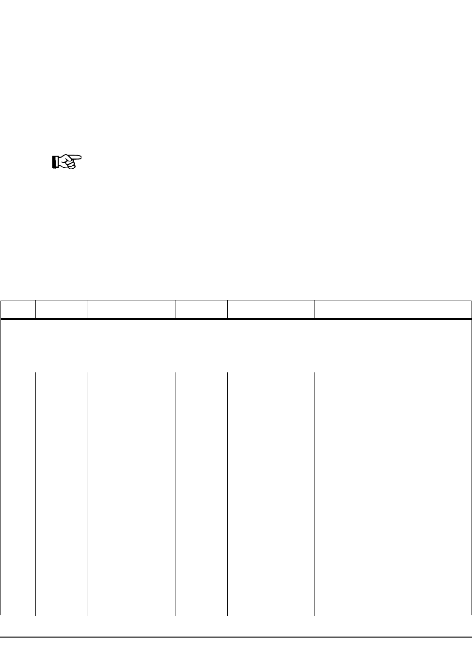
582 VM/HSC 6.0 System Programmer’s Guide
1st ed., 6/30/04 - 312579601
SLUVVDAT
To determine the HSC release that produced a volume report flat file, use the CDSDATA
parameter to create flat file records with non-volume information.
Interrogate the CDSLEVEL field in the SLUVIDAT (CDS Information) record. A CDS at
level 02.00.00 is reported by an HSC VOLRpt at release level 2.0.1 and earlier. CDS level
02.01.00 is reported by an HSC 5.0, 5.1, or 6.0 VOLRpt.
The CDSDATA records are appended to the VOLDATA records. To interrogate the CDS
level before processing the volume records, extract the CDSDATA and VOLDATA in
different steps to create separate files.
Notes:
1. The Batch API request formats the date fields VOLDTINS, VOLDTSEL, and
VOLTMNT as ‘‘yyyymmdd.’’
2. The Batch API request does not report volume subpool labels or IDs. Fields
VOLSPLBL and VOLSPID are blank-filled.
3. When a volume has been mounted, the VOLERMNT and VOLERACT bit values are
both set in VOLFLAG2. If the volume is errant, the VOLERMNT bit value is not set
in VOLFLAG2, but the VOLERACT bit value is set.
Table 63. SLUVVDAT Record Format
Dec Hex Type Length Label Description
SLUVVDAT - FLAT FILE VOLUME DATA DSECT
FUNCTION:
DESCRIBES THE VOLUME DATA WHICH MAY BE GENERATED TO THE FLAT FILE BY THE VOLUME
REPORT UTILITY
0 (0) STRUCTURE SLUVVDAT
0 (0) CHARACTER 1 -RESERVED- RECORD TYPE (C’V’)
1 (1) BITSTRING 1 VOLMEDIA VOLUME MEDIA TYPE
‘1’ (F1) CHAR CONST VOLMEDST STANDARD MEDIA
‘1’ (F1) CHAR CONST VOLMEDT1 (X’F1’) STANDARD MEDIA
‘A’ (C1) CHAR CONST VOLMEDTA (X’C1’) HELICAL MEDIA “A”
‘B’ (C2) CHAR CONST VOLMEDTB (X’C2’) HELICAL MEDIA “B”
‘C’ (C3) CHAR CONST VOLMEDTC (X’C3’) HELICAL MEDIA “C”
‘D’ (C4) CHAR CONST VOLMEDTD (X’C4’) HELICAL CLEANING
CARTRIDGE
‘E’ (C5) CHAR CONST VOLMEDTE (X’C5’) ECART MEDIA
‘J’ (D1) CHAR CONST VOLMEDTJ (X’D1’) JCART MEDIA
‘P’ (D7) CHAR CONST VOLMEDTP (X’D7’) STK2P MEDIA

Appendix C. Record Formats 583
1st ed., 6/30/04 - 312579601
‘R’ (D9) CHAR CONST VOLMEDTR (X’D9’) STK1R MEDIA
‘U’ (E4) CHAR CONST VOLMEDTU (X’E4’) STK1U CLEANING
CARTRIDGE “U”
‘W’ (E7) CHAR CONST VOLMEDTW (X’E7’) STK2W CLEANING
CARTRIDGE “W”
‘Z’ (E9) CHAR CONST VOLMEDTZ (X’E9’) ZCART MEDIA
2 (2) BITSTRING 1 VOLFLAG1 VOLUME FLAG BYTE 1
1... .... X’80’ VOLSCR 1... .... - VOLUME IS SCRATCH
.1.. .... X’40’ VOLSEL .1.. .... - VOLUME IS SELECTED
..1. .... X’20’ VOLEXLBL ..1. .... - VOLUME HAS
EXTERNAL LABEL
...1 .... X’10’ VOLEXRD ...1 .... - EXTERNAL LABEL IS
OCR READABLE
.... 1... X’08’ VOLINUSE .... 1... - THIS RECORD IS IN USE
.... ...1 X’01’ VOLNILIB .... ...1 - VOLUME NOT IN LIB.
3 (3) HEXSTRING 1 VOLOHID OWNING HOST ID
4 (4) SIGNED-FWORD 4 VOLSELCT VOLUME SELECTION COUNT
8 (8) CHARACTER 6 VOLSER VOLUME SERIAL NUMBER,
LEFT JUSTIFIED AND BLANK
FILLED.
14 (E) CHARACTER 14 VOLHMLOC HOME LOCATION
14 (E) CHARACTER 2 VOLHMACS READABLE HEXADECIMAL ACS
NUMBER WHERE THE VOLUME
RESIDES.
16 (10) CHARACTER 1 -RESERVED- ‘:’
17 (11) CHARACTER 2 VOLHMLSM READABLE HEXADECIMAL LSM
# IN VOLHMACS WHERE THE
VOLUME RESIDES
19 (13) CHARACTER 1 -RESERVED- ‘:’
20 (14) CHARACTER 2 VOLHMPNL DECIMAL NUMBER OF THE
PANEL WITHIN VOLHMLSM
WHERE THE VOLUME RESIDES.
22 (16) CHARACTER 1 -RESERVED- ‘:’
23 (17) CHARACTER 2 VOLHMROW DECIMAL NUMBER OF THE
ROW WITHIN VOLHMPNL
WHERE THE VOLUME RESIDES.
25 (19) CHARACTER 1 -RESERVED- ‘:’
Table 63. SLUVVDAT Record Format (Continued)
Dec Hex Type Length Label Description

584 VM/HSC 6.0 System Programmer’s Guide
1st ed., 6/30/04 - 312579601
26 (1A) CHARACTER 2 VOLHMCEL DECIMAL NUMBER OF THE
COLUMN WITHIN VOLHMROW
WHERE THE VOLUME RESIDES.
28 (1C) CHARACTER 3 VOLSPLBL VOLUME SUBPOOL LABEL
TYPE
‘SL’ (E2D3) CHAR CONST VOLSPSL STANDARD LABEL
‘NL’ (D5D3) CHAR CONST VOLSPNL NON-LABELLED
‘AL’ (C1D3) CHAR CONST VOLSPAL ANSI LABEL
‘NSL’ (D5E2D3) CHAR CONST VOLSPNSL NON-STANDARD LABEL
‘ ‘ (404040) CHAR CONST VOLSPNON ‘ SUBPOOL INFO NOT
REQUESTED OR NOT
AVA I L A B L E
31 (1F) CHARACTER 13 VOLSPID VOLUME SUBPOOL ID (13-BYTE
NAME OF POOL IF USING
SCRPOOL STATEMENTS; 3- BYTE
SUBPOOL INDEX NUMBER IF
USING SLSUX03)
44 (2C) SIGNED-HWORD 2 VOLMXCLN VOLUME MAXCLEAN VALUE
46 (2E) SIGNED-HWORD 2 -RESERVED- * RESERVED *
48 (30) SIGNED-FWORD 4 -RESERVED-(2) * RESERVED *
THE FOLLOWING FIELDS:
VOLTDINS, VOLTDSEL, VOLTDMNT
CONTAIN THE HIGH-ORDER FULLWORD OF THE CPU TOD CLOCK VALUE WHEN
THE VOLUME WAS (RESPECTIVELY) ENTERED INTO THE LIBRARY, LAST
SELECTED, AND LAST MOUNTED.
FOR EACH OF THESE FIELDS, THE LOW-ORDER BIT (BIT 31) HAS A
VALUE EQUAL TO 2-TO-THE-20TH-POWER MICROSECONDS, OR 1.048576
SECONDS SINCE MIDNIGHT, JANUARY 1, 1900. THIS TIME IS
UNCORRECTED FOR ANY LOCAL TIME ZONE OFFSET FROM GMT. THIS IS
THE SAME FORMAT WHICH IS USED BY THE HSC TO SAVE THIS
INFORMATION.
THE VALUES IN FIELDS: VOLDTINS, VOLTMINS, VOLDTSEL, VOLTMSEL, VOLDTMNT, VOLTMMNT
HAVE BEEN CORRECTED FOR LOCAL TIME OFFSET FROM GMT. THESE
TIMES (AND POSSIBLY THE DATES) MAY THEREFORE BE DIFFERENT
FROM VALUES CALCULATED USING THE TOD CONTENTS IN
VOLTDINS, VOLTDSEL, AND VOLTDMNT.
56 (38) SIGNED-FWORD 4 VOLTDINS TOD CLOCK VALUE WHEN
VOLUME WAS INSERTED INTO
THE LIBRARY
60 (3C) SIGNED-FWORD 4 VOLTDSEL TOD CLOCK VALUE WHEN
VOLUME WAS LAST SELECTED
64 (40) SIGNED-FWORD 4 VOLTDMNT TOD CLOCK VALUE WHEN
VOLUME WAS LAST
MOUNTEDD
Table 63. SLUVVDAT Record Format (Continued)
Dec Hex Type Length Label Description

Appendix C. Record Formats 585
1st ed., 6/30/04 - 312579601
68 (44) CHARACTER 8 VOLDTINS DATE VOLUME INSERTED INTO
THE LIBRARY FORMAT
DETERMINED BY VOLD4YR
76 (4C) CHARACTER 8 VOLTMINS TIME VOLUME INSERTED INTO
THE LIBRARY (HH:MM:SS)
84 (54) CHARACTER 8 VOLDTSEL DATE VOLUME LAST SELECTED
FORMAT DETERMINED BY
VOLD4YR
92 (5C) CHARACTER 8 VOLTMSEL TIME VOLUME LAST SELECTED
(HH:MM::SS)
100 (64) CHARACTER 8 VOLDTMNT DATE VOLUME LAST MOUNTED
FORMAT DETERMINED BY
VOLD4YR
108 (6C) CHARACTER 8 VOLTMMNT TIME VOLUME LAST MOUNTED
(HH:MM:SS)
116 (74) BITSTRING 1 VOLFLAG3 VOLUME FLAG BYTE 3
1... .... X’80’ VOLD4YR INDICATES DATE FORMAT ON -
YYYYMMDD FORMAT OFF -
MM/DD/YY FORMAT
..1. .... X’20’ VOLMNDSM AFFECTS
VOLDTMNT/VOLTMMNT FLDS
ON - TIME/DATE LAST
MOUNTED@02 OFF - TIME/DATE
DISMOUNTED
.... ..1. X’02’ VOLNOUSE VOLUME NOT USABLE
117 (75) HEXSTRING 3 -RESERVED- RESERVED
120 (78) LENGTH VOLLNGTH
THE FOLLOWING SECTION IS FILLED IN ONLY IF THE VOLUME WAS FOUND TO
BE EITHER IN TRANSIT OR ERRANT.
120 (78) BITSTRING 1 VOLFLAG2 VOLUME FLAG BYTE 2
*************************
FOR IN-TRANSIT VOLUMES:
*************************
1... .... X’80’ VOLITUSE 1... .... - RECORD IN USE
.1.. .... X’40’ VOLITACQ .1.. .... - RECORD HAS BEEN
ACQUIRED
*********************
FOR ERRANT VOLUMES:
*********************
1... .... X’80’ VOLERACT 1... .... - RECORD IS ACTIVE
.1.. .... X’40’ VOLERLIL .1.. .... - LOST IN LSM POSSIBLE
Table 63. SLUVVDAT Record Format (Continued)
Dec Hex Type Length Label Description

586 VM/HSC 6.0 System Programmer’s Guide
1st ed., 6/30/04 - 312579601
..1. .... X’20’ VOLERSSC ..1. .... - SOURCE LOC. SCANNED
...1 .... X’10’ VOLERDSC ...1 .... - DEST. LOC. SCANNED
.... 1... X’08’ VOLERLSC .... 1... - LOST IN LSM SCANNED
.... .1.. X’04’ VOLERHSC .... .1.. - HOME LSM SCANNED
.... ..1.X’02’ VOLERMNT .... ..1.- VOLUME IS MOUNTED
121 (79) BITSTRING 1 VOLITTAG IN-TRANSIT TAG TYPE
.... .... X’00’ VOLITOTH .... .... - OTHER (OR NOT IN TRAN)
.... ...1 X’01’ VOLITCAP .... ...1 - CAP
.... ..1. X’02’ VOLITCEL .... ..1. - CELL
.... .1.. X’04’ VOLITLSM .... .1.. - LSM ID
.... 1... X’08’ VOLITVOL .... 1... - VOLUME
.... 1.1. X’0A’ VOLITLOC .... 1.1. - LIBRARY LOCATION
(VOLITVOL+VOLITCEL)
122 (7A) BITSTRING 1 VOLITRTN RECOVERY ROUTINE FLAG (IN
TRAN. ON)
.... .1.. X’04’ VOLRRAUS .... .1.. - AUDIT START
.... 1... X’08’ VOLRRALD .... 1... - AUDIT LOGICAL DELETE
...1 .... X’10’ VOLRRMNT ...1 .... - MOUNT
...1 .1.. X’14’ VOLRRDEJ ...1 .1.. - DISMOUNT EJECT
...1 1... X’18’ VOLRRCLU ...1 1... - CLEANER UPDATE
...1 11.. X’1C’ VOLRRCLS ...1 11.. - CLEANER SELECT
..1. .... X’20’ VOLRRSCA ..1. .... - SCRATCH ADD
..1. .1.. X’24’ VOLRRSCD ..1. .1.. - SCRATCH DELETE
..1. 1... X’28’ VOLRRVDL ..1. 1... - VOLUME DELETE
..1. 11.. X’2C’ VOLRRERR ..1. 11.. - ERRANT PROCESSING
..11 .... X’30’ VOLRRCAP ..11 .... - CAP
..11 .1.. X’34’ VOLRRCNL ..11 .1.. - CONFIG LSM
..11 1... X’38’ VOLRRSUA ..11 1... - SCRATCH UPDATE ADD
..11 11.. X’3C’ VOLRRSLV ..11 11.. - SELECTED VOLUME
.1.. .... X’40’ VOLRRSRE .1.. .... - SCRATCH
REDISTRIBUTION
.1.. .1.. X’44’ VOLRRMCT .1.. .1.. - MOVE CARTRIDGE
Table 63. SLUVVDAT Record Format (Continued)
Dec Hex Type Length Label Description

Appendix C. Record Formats 587
1st ed., 6/30/04 - 312579601
123 (7B) HEXSTRING 3 -RESERVED- * RESERVED
126 (7E) HEXSTRING 6 VOLSRCE SOURCE LOCATION
132 (84) HEXSTRING 6 VOLDEST DESTINATION LOCATION
138 (8A) CHARACTER 2 VOLLILSM “LOST IN” LSM
140 (8C) CHARACTER 8 VOLRECC RECTECH CHAR FORM
148 (94) CHARACTER 8 VOLMEDC MEDIA CHAR FORM
156 (9C) LENGTH VOLIELEN LENGTH OF MAIN VOLUME
SECTION PLUS
IN-TRANSIT/ERRANT
INFORMATION
THE VOLSRCE AND VOLDEST FIELDS MAY BE MAPPED BY THE FOLLOWING DSECT.
0 (0) STRUCTURE VOLLOC
0 (0) CHARACTER 1 VOLSTYPE SOURCE TYPE
‘1’ (F1) CHAR CONST VOLSCELL CELL
‘2’ (F2) CHAR CONST VOLSCAP CAP
‘3’ (F3) CHAR CONST VOLSDRIV DRIVE
‘4’ (F4) CHAR CONST VOLSOTHR OTHER
1 (1) HEXSTRING 1 VOLSACSN ACS NUMBER
2 (2) HEXSTRING 1 VOLSLSMN LSM NUMBER
******************
FOR “CELL” TYPES
******************
3 (3) HEXSTRING 1 VOLSPNLN PANEL NUMBER
4 (4) HEXSTRING 1 VOLSROWN ROW NUMBER
5 (5) HEXSTRING 1 VOLSCOLN COLUMN (CELL) NUMBER
*****************
FOR “CAP” TYPES
*****************
3 (3) HEXSTRING 2 VOLSCLOC CAP LOCATION
5 (5) HEXSTRING 1 -RESERVED- RESERVED
*******************
FOR “DRIVE” TYPES
*******************
3 (3) HEXSTRING 1 VOLSDPNL DRIVE PANEL NUMBER
4 (4) HEXSTRING 1 VOLSDNUM DRIVE NUMBER
Table 63. SLUVVDAT Record Format (Continued)
Dec Hex Type Length Label Description

588 VM/HSC 6.0 System Programmer’s Guide
1st ed., 6/30/04 - 312579601
5(5) HEXSTRING 1 -RESERVED- RESERVED
3 (3) HEXSTRING 1 VOLSDIDX DRIVE INDEX NUMBER
4 (4) HEXSTRING 1 -RESERVED- RESERVED
5 (5) BITSTRING 1 VOLSDFLG DRIVE FORMAT FLAG
1111 1111 X’FF’ VOLSDFIX DRIVE IS DRIVE INDEX FORMAT
6 (6) HEXSTRING 2 -RESERVED- RESERVED
FOR “OTHER” TYPES, THIS RECORD IS TREATED AS IF THE VOLUME WERE ERRANT.
Table 63. SLUVVDAT Record Format (Continued)
Dec Hex Type Length Label Description

Appendix C. Record Formats 589
1st ed., 6/30/04 - 312579601
Cross Reference
Name Len
Offset
Value
VOLDEST 000006 84
VOLDTINS 000008 44
VOLDTMNT 000008 64
VOLDTSEL 000008 54
VOLD4YR - 80
VOLERACT - 80
VOLERDSC - 10
VOLERHSC - 04
VOLERLIL - 40
VOLERLSC - 08
VOLERMNT - 02
VOLERSSC - 20
VOLEXLBL - 20
VOLEXRD - 10
VOLFLAG1 000001 02
VOLFLAG2 000001 78
VOLFLAG3 000001 74
VOLHMACS 000002 0E
VOLHMCEL 000002 1A
VOLHMLOC 000014 0E
VOLHMLSM 000002 11
VOLHMPNL 000002 14
VOLHMROW 000002 17
VOLIELEN - 9C
VOLINUSE - 08
VOLITACQ - 40
VOLITCAP - 01
VOLITCEL - 02
VOLITLOC - 0A
VOLITLSM - 04
VOLITOTH - 00

590 VM/HSC 6.0 System Programmer’s Guide
1st ed., 6/30/04 - 312579601
VOLITRTN 000001 7A
VOLITTAG 000001 79
VOLITUSE - 80
VOLITVOL - 08
VOLLILSM 000002 8A
VOLLNGTH - 78
VOLMEDC 000008 94
VOLMEDIA 000001 01
VOLMEDST - ‘CVAL’
VOLMEDTA - ‘CVAL’
VOLMEDTB - ‘CVAL’
VOLMEDTC - ‘CVAL’
VOLMEDTD - ‘CVAL’
VOLMEDTE - ‘CVAL’
VOLMEDTJ - ‘CVAL’
VOLMEDTP - ‘CVAL’
VOLMEDTR - ‘CVAL’
VOLMEDTU - ‘CVAL’
VOLMEDTW - ‘CVAL’
VOLMEDTZ - ‘CVAL’
VOLMEDT1 - ‘CVAL’
VOLMNDSM - 20
VOLMXCLN 000002 2C
VOLNILIB - 01
VOLNOUSE - 02
VOLOHID 000001 03
VOLRECC 000008 8C
VOLRRALD - 08
VOLRRAUS - 04
VOLRRCAP - 30
VOLRRCLS - 1C
VOLRRCLU - 18
Name Len
Offset
Value

Appendix C. Record Formats 591
1st ed., 6/30/04 - 312579601
VOLRRCNL - 34
VOLRRDEJ - 14
VOLRRERR - 2C
VOLRRMCT - 44
VOLRRMNT - 10
VOLRRSCA - 20
VOLRRSCD - 24
VOLRRSLV - 3C
VOLRRSRE - 40
VOLRRSUA - 38
VOLRRVDL - 28
VOLSACSN 000001 01
VOLSCAP - ‘CVAL’
VOLSCELL - ‘CVAL’
VOLSCLOC 000002 03
VOLSCOLN 000001 05
VOLSCR - 80
VOLSDFIX - FF
VOLSDFLG 000001 05
VOLSDIDS 000001 03
VOLSDNUM 000001 04
VOLSDPNL 000001 03
VOLSDRIV - ‘CVAL’
VOLSEL - 40
VOLSELCT 000004 04
VOLSER 000006 08
VOLSLSMN 000001 02
VOLSOTHR - ‘CVAL’
VOLSPAL - ‘CVAL’
VOLSPID 000013 1F
VOLSPLBL 000003 1C
VOLSPNL - ‘CVAL’
Name Len
Offset
Value

592 VM/HSC 6.0 System Programmer’s Guide
1st ed., 6/30/04 - 312579601
VOLSPNLN 000001 03
VOLSPNON - ‘CVAL’
VOLSPNSL - ‘CVAL’
VOLSPSL - ‘CVAL’
VOLSRCE 000006 7E
VOLSROWN 000001 04
VOLSTYPE 000001 00
VOLTDINS 000004 38
VOLTDMNT 000004 40
VOLTDSEL 000004 3C
VOLTMINS 000008 4C
VOLTMMNT 000008 6C
VOLTMSEL 000008 5C
Name Len
Offset
Value

Appendix C. Record Formats 593
1st ed., 6/30/04 - 312579601
Batch API Records
Batch API Mapping Macros
These SMP/E-distributed macros map only Batch API records. Refer to “Volume Report
and Batch API Records” on page 562 to see the records that map both Volume Report and
Batch API.
Table 64. Mapping macros for Batch API Records
Macro Description
SLUVDDAT Batch API Drive Information DSECT
SLUVPDAT Batch API CAP Information DSECT

594 VM/HSC 6.0 System Programmer’s Guide
1st ed., 6/30/04 - 312579601
Batch API Record Formats
SLUVDDAT
This record is produced only by the Batch API QCDS request. Refer to Appendix E,
“Batch Application Program Interface (API)” on page 713 for more information.
Table 65. SLUVDDAT Record Format
Dec Hex Type Length Label Description
SLUVDDAT - QCDS DRIVE INFORMATION DSECT
FUNCTION:
MAPS THE DRIVE DATA PRODUCED BY THE QCDS READ REQUEST
FOR THE CDS DRV RECORD AREA.
0 (0) STRUCTURE SLUVDDAT
0 (0) CHARACTER 1 UVDRT RECORD TYPE
1 (1) BITSTRING 1 UVDFLAG1 STATUS FLAG:
1... .... X’80’ UVDDCLN DRIVE NEEDS CLEANING
2 (2) BITSTRING 1 UVDFLAG2 MOUNT ERROR FLAG:
1... .... X’80’ UVDBMNT MOUNT ERROR
.1.. .... X’40’ UVDOPRQ OPER INTERV REQD BY UX01
..1. .... X’20’ UVDV5310 IAT5310 ERROR MESSAGE ISSUED
3 (3) BITSTRING 1 UVDFLAG3 SCRATCH MOUNT FLAG:
1... .... X’80’ UVDSCR SCRATCH MOUNT
.1.. .... X’40’ UVDNSCR NON-SCRATCH MOUNT
..1. .... X’20’ UVD501E IEC501E MSG PREVIOUSLY
PROCESSED
...1 .... X’10’ UVDRACF RACF READ OPTION WAS SET
.... 1... X’08’ UVDTMS7 MESSAGE IECTMS7 BEING
PROCESSED
4 (4) CHARACTER 2 UVDTYPE DRIVE TYPE FROM LMU:
‘64’ (F6F4) CHAR CONST UVD4480 4480 DRIVE
‘32’ (F3F2) CHAR CONST UVDTIMB TIMBERLINE DRIVE
‘33’ (F3F3) CHAR CONST UVD9491 9490EE DRIVE
‘16’ (F1F6) CHAR CONST UVDREDW REDWOOD
‘08’ (F0F8) CHAR CONST UVDSILV SILVERTON
‘06’ (F0F6) CHAR CONST UVD3590 T9940A ACTING AS A 3590
‘05’ (F0F5) CHAR CONST UVD3490E T9940A ACTING AS A 3490E

Appendix C. Record Formats 595
1st ed., 6/30/04 - 312579601
Cross Reference
‘01’ (F0F1) CHAR CONST UVD984B4 T9840B ACTING AS A 3490E
‘07’ (F0F7) CHAR CONST UVD984B5 T9840B ACTING AS A 3590
‘09’ (F0F9) CHAR CONST UVD994B4 T9940B ACTING AS A 3490E
‘10’ (F1F0) CHAR CONST UVD994B5 T9940B ACTING AS A 3590
‘02’ (F0F2) CHAR CONST UVD9840 9840 DRIVE
‘03’ (F0F3) CHAR CONST UVD98405 9840 DRIVE ACTING AS A 3590
65535 (FFFF) CONST UVDNOLMU LMU DRIVE TYPE NOT YET SET
6 (6) AREA 4 UVDDRVID DRIVEID:
6 (6) HEXSTRING 1 UVDIDACS DRIVEID ACS
7 (7) HEXSTRING 1 UVDIDLSM DRIVEID LSM
8 (8) HEXSTRING 1 UVDIDPNL DRIVEID PANEL
9 (9) HEXSTRING 1 UVDIDNUM DRIVEID NUMBER WITHIN PANEL
12 (C) SIGNED-FWORD 4 UVDDEFIN DRIVE IS DEFINED TO A HOST -
BIT-MAP REPRESENTING EACH
HOST THAT HAS THIS DRIVE
DEFINED, READING FROM LEFT
TO RIGHT IN HOST INDEX ORDER
16 (10) SIGNED-HWORD 2 UVDNUNIT NUMBER OF DRIVE UNITS (FOR
UVDUNITN)
18 (12) SIGNED-HWORD 2 UVDLUNIT LENGTH OF DRIVE UNITS (FOR
UVDUNITN)
20 (14) SIGNED-HWORD 2 UVDUNITN(16) MVS UNIT NUMBERS INDEXED
BY HOST.
52 (34) LENGTH UVDLEN RECORD LENGTH
Name Len
Offset
Value
UVDBMNT - 80
UVDDCLN - 80
UVDDEFIN 000004 0C
UVDDRVID 000004 06
UVDFLAG1 000001 01
Table 65. SLUVDDAT Record Format (Continued)
Dec Hex Type Length Label Description

596 VM/HSC 6.0 System Programmer’s Guide
1st ed., 6/30/04 - 312579601
UVDFLAG2 000001 02
UVDFLAG3 000001 03
UVDIDACS 000001 06
UVDIDLSM 000001 07
UVDIDNUM 000001 09
UVDIDPNL 000001 08
UVDLEN - 34
UVDLUNIT 000002 12
UVDNOLMU - FFFF
UVDNSCR - 40
UVDNUNIT 000002 10
UVDOPRQ - 40
UVDRACF - 10
UVDREDW - ‘CVAL’
UVDRT 000001 00
UVDSCR - 80
UVDSILV - ‘CVAL’
UVDTIMB - ‘CVAL’
UVDTMS7 - 08
UVDTYPE 000002 04
UVDUNITN 000002 14
UVDV5310 - 20
UVD3490E - ‘CVAL’
UVD3590 - ‘CVAL’
UVD4480 - ‘CVAL’
UVD501E - 20
UVD9491 - ‘CVAL’
UVD984B4 - ‘CVAL’
UVD984B5 - ‘CVAL’
UVD9840 - ‘CVAL’
UVD98405 - ‘CVAL’
UVD994B4 - ‘CVAL’
Name Len
Offset
Value

Appendix C. Record Formats 597
1st ed., 6/30/04 - 312579601
UVD994B5 - ‘CVAL’
Name Len
Offset
Value

598 VM/HSC 6.0 System Programmer’s Guide
1st ed., 6/30/04 - 312579601
SLUVPDAT
This record is produced only by the Batch API QCDS request. Refer to Appendix E,
“Batch Application Program Interface (API)” on page 713 for more information.
Table 66. SLUVPDAT Record Format
Dec Hex Type Length Label Description
SLUVPDAT - QCDS CAP INFORMATION DSECT
FUNCTION:
MAPS THE CAP DATA PRODUCED BY THE QCDS READ REQUEST
FOR THE CDS CAP RECORD AREA.
0 (0) STRUCTURE SLUVPDAT
0 (0) CHARACTER 1 UVPRT RECORD TYPE
1 (1) BITSTRING 1 UVPFLAG1 CAP STATUS:
1... .... X’80’ UVPF1ACT CAP IS ACTIVE
.1.. .... X’40’ UVPF1REC CAP NEEDS RECOVERY
..1. .... X’20’ UVPF1AUT CAP IS IN AUTOMATIC MODE
...1 .... X’10’ UVPF1LNK CAP IS LINKED
.... 1... X’08’ UVPF1ONL CAP IS ONLINE
2 (2) BITSTRING 1 UVPFLAG2 CAP MODE:
1... .... X’80’ UVPF2ENT CAP IS ENTERING
.1.. .... X’40’ UVPF2DRA CAP IS DRAINING
..1. .... X’20’ UVPF2EJT CAP IS EJECTING
...1 .... X’10’ UVPF2CLN CAP IS CLEANING
.... 1... X’08’ UVPF2IDL CAP IS IDLE
3 (3) HEXSTRING 3 UVPID CAP ID
6 (6) CHARACTER 8 UVPJOBN JOBNAME OF OWNER
14 (E) CHARACTER 8 UVPHOST HOSTID IF CAP IS ACTIVE
22 (16) HEXSTRING 1 UVPHOSTI HOST INDEX FOR CAPHOST
24 (18) SIGNED-HWORD 2 UVPNCELL NUMBER OF CELLS IN CAP
26 (1A) HEXSTRING 1 UVPNROWS NUMBER OF ROWS IN THIS CAP
27 (1B) HEXSTRING 1 UVPNCOLS NUMBER OF COLUMNS IN THIS CAP
28 (1C) HEXSTRING 1 UVPNMAGS NUMBER OF MAGAZINES IN THIS
CAP
29 (1D) HEXSTRING 1 UVPNMAGC NUMBER OF CELLS PER MAGAZINE
30 (1E) SIGNED-HWORD 2 UVPNPRIO NUMBER OF CAP PRIORITY
ELEMENTS

Appendix C. Record Formats 599
1st ed., 6/30/04 - 312579601
32 (20) SIGNED-HWORD 2 UVPLPRIO LENGTH OF CAP PRIORITY
ELEMENTS
34 (22) HEXSTRING 1 UVPPRITY(16) CAP PRIORITY ELEMENTS, BY HOST
INDEX
50 (32) HEXSTRING 1 UVPPANEL PANEL NUMBER OF CAP
51 (33) BITSTRING 1 UVPTYPE TYPE OF CAP:
1... .... X’80’ UVPPCAP PRIORITY CAP
.... ...1 X’01’ UVPCIM CIMARRON
.... ..1. X’02’ UVPCLIP CLIPPER
.... ..11 X’03’ UVPTWSTD STANDARD WOLF CLIPPER
.... .1.. X’04’ UVPTWOPT OPTIONAL WOLF CLIPPER
.... .1.1 X’05’ UVP9740 9740 CAP (CELLS SET AT VARY LSM)
52 (34) LENGTH UVPLEN RECORD LENGTH
Table 66. SLUVPDAT Record Format (Continued)
Dec Hex Type Length Label Description

600 VM/HSC 6.0 System Programmer’s Guide
1st ed., 6/30/04 - 312579601
Cross Reference
Name Len
Offset
Value
UVPCIM - 01
UVPCLIP - 02
UVPFLAG1 000001 01
UVPFLAG2 000001 02
UVPF1ACT - 80
UVPF1AUT - 20
UVPF1LNK - 10
UVPF1ONL - 08
UVPF1REC - 40
UVPF2CLN - 10
UVPF2DRA - 40
UVPF2EJT - 20
UVPF2ENT - 80
UVPF2IDL - 08
UVPHOST 000008 0E
UVPHOSTI 000001 16
UVPID 000003 03
UVPJOBN 000008 06
UVPLEN - 34
UVPLPRIO 000002 20
UVPNCELL 000002 18
UVPNCOLS 000001 1B
UVPNMAGC 000001 1D
UVPNMAGS 000001 1C
UVPNPRIO 000002 1E
UVPNROWS 000001 1A
UVPPANEL 000001 32
UVPPCAP - 80
UVPPRITY 000001 22
UVPRT 000001 00
UVPTWOPT - 04

Appendix C. Record Formats 601
1st ed., 6/30/04 - 312579601
UVPTWSTD - 03
UVPTYPE 000001 33
UVP9740 - 05
Name Len
Offset
Value

602 VM/HSC 6.0 System Programmer’s Guide
1st ed., 6/30/04 - 312579601
Appendix D. Logging ACS Robotics Motion 603
1st ed., 6/30/04 - 312579601
Appendix D. Logging ACS Robotics Motion
Overview
StorageTek provides a way to monitor the reliability of ACS robotics motion. This
appendix describes what information is logged and how that information is logged.
Information Being Logged
StorageTek logs robotic motion statistics in three categories:
• robotic Motion Start Counts
• temporary Motion Error Counts
• permanent Motion Errors.
Each category is described in the following paragraphs.
Note: Robotic motion start counts and temporary motion errors will only be recorded if
OPTION LOGGING is set to EXTENDED.
Robotics Motion Start Counts
Each time an LSM robotics motion request is accepted by the LMU, the count of Robotics
Motion Starts is incremented by one. This count represents the number of times the robot
attempts to pick up a cartridge at one location, move it, and place it at another location.
When the Catalog or VIew commands are used, the count is the number of times the robot
hand is moved to a target location. The Robotics Motion Start Count is incremented at the
start of each robotics motion. The motion itself may be successful, have a temporary error
or have a permanent failure.
With the exception of LMU busy retries, motions retried by the HSC are counted as
additional subsequent motions, since each attempted motion request could result in a
hardware failure (hard fail) or temporary error.
Temporary Motion Error Counts
For each motion which is successful, but which had a temporary error, the count of
Temporary Motion Errors is incremented by one. A temporary error is counted against any
motion that contains a retry at some level which either impacts performance or may
indicate that hardware is degraded. Temporary errors are currently counted at the LSM
level against any motion requiring a panel ID recalibration to complete. Temporary errors
are counted at the LMU level if a motion must be retried.

604 VM/HSC 6.0 System Programmer’s Guide
1st ed., 6/30/04 - 312579601
Permanent Motion Errors
Each time a permanent motion failure occurs, complete information concerning the failure
is logged. A permanent error is counted against any motion which causes a Mount,
DISMount, Swap, MOVe, Catalog, or VIew command to fail in such a way that user
intervention is required to correct the situation.

Appendix D. Logging ACS Robotics Motion 605
1st ed., 6/30/04 - 312579601
How Information is Logged
The HSC periodically retrieves the statistics for robotics motions begun and temporary
errors from the LMU. This information is logged to SYS1.LOGREC as software errors as
shown in the Table 67. This record is a valid ‘‘Initiated and Temporary Error Motion
Software Error Record’’ only under the following circumstances:
• if the Record Type Field (bytes 642-643) has value X’6506’ and
• the StorageTek identifier (X’FEEDFACE’ at bytes 644-647) is present.
Such a record is called an LLG6 record. Refer to Appendix C, “Record Formats” on page
497 to see the record layout for LLG6.
Table 67. Format for Total Motions and Temporary Error Counts
Initiated and Temporary Error Motion Software Error Record
BYTE # Description of Field
00-31 Standard HSC LOGREC header
00-00 X’40’ indicates software detected error
01-01 X’80’ indicates VS2 or later release level
02-02 X’08’ indicates TIME macro was used
03-03 X’20’ indicates record contains an error ID
04-05 Reserved
06-06 Record count
07-07 Reserved
08-11 System date of error
12-15 System time of error
16-23 CPU ID
24-31 Subsystem name
32-35 Eyeball characters ‘LLG6’
36-41 Proprietary data
42-43 Reserved
44-44 ACSid (binary)
45-45 Reserved

606 VM/HSC 6.0 System Programmer’s Guide
1st ed., 6/30/04 - 312579601
46-46 LSM Configuration Flag 1st Byte
X’80’ - LSM 0 exists if flag is on
X’40’ - LSM 1 exists if flag is on
X’20’ - LSM 2 exists if flag is on
X’10’ - LSM 3 exists if flag is on
X’08’ - LSM 4 exists if flag is on
X’04’ - LSM 5 exists if flag is on
X’02’ - LSM 6 exists if flag is on
X’01’ - LSM 7 exists if flag is on
47-47 LSM Configuration Flag 2nd Byte
X’80’ - LSM 8 exists if flag is on
X’40’ - LSM 9 exists if flag is on
X’20’ - LSM 10 exists if flag is on
X’10’ - LSM 11 exists if flag is on
X’08’ - LSM 12 exists if flag is on
X’04’ - LSM 13 exists if flag is on
X’02’ - LSM 14 exists if flag is on
X’01’ - LSM 15 exists if flag is on
48-51 LSM 0 Robotic motions started (binary)
52-55 LSM 0 Temporary motion error counts (binary)
56-59 LSM 1 Robotic motions started (binary)
60-63 LSM 1 Temporary motion error counts (binary)
64-67 LSM 2 Robotic motions started (binary)
68-71 LSM 2 Temporary motion error counts (binary)
72-75 LSM 3 Robotic motions started (binary)
76-79 LSM 3 Temporary motion error counts (binary)
80-83 LSM 4 Robotic motions started (binary)
84-87 LSM 4 Temporary motion error counts (binary)
88-91 LSM 5 Robotic motions started (binary)
92-95 LSM 5 Temporary motion error counts (binary)
96-99 LSM 6 Robotic motions started (binary)
100-103 LSM 6 Temporary motion error counts (binary)
104-107 LSM 7 Robotic motions started (binary)
108-111 LSM 7 Temporary motion error counts (binary)
112-115 LSM 8 Robotic motions started (binary)
116-119 LSM 8 Temporary motion error counts (binary)
120-123 LSM 9 Robotic motions started (binary)
Table 67. Format for Total Motions and Temporary Error Counts (Continued)
Initiated and Temporary Error Motion Software Error Record
BYTE # Description of Field

Appendix D. Logging ACS Robotics Motion 607
1st ed., 6/30/04 - 312579601
The HSC also makes a log entry for each permanent error, codes and indicates whether or
not the errors are considered permanent errors.
The record format used to log a hard fail to SYS1.LOGREC is shown in Table 68. This
record is a valid ‘‘Motion Hard Fail Software Error Record’’ only under the following
conditions:
• if the Record Type Field (bytes 642-643) has a value of X’6501’,
• the StorageTek identifier (X’FEEDFACE’ at bytes 644-647) is present, and
• the character ‘H’ appears at the byte 113 location.
124-127 LSM 9 Temporary motion error counts (binary)
128-131 LSM 10 Robotic motions started (binary)
132-135 LSM 10 Temporary motion error counts (binary)
136-139 LSM 11 Robotic motions started (binary)
140-143 LSM 11 Temporary motion error counts (binary)
144-147 LSM 12 Robotic motions started (binary)
148-151 LSM 12 Temporary motion error counts (binary)
152-155 LSM 13 Robotic motions started (binary)
156-159 LSM 13 Temporary motion error counts (binary)
160-163 LSM 14 Robotic motions started (binary)
164-167 LSM 14 Temporary motion error counts (binary)
168-171 LSM 15 Robotic motions started (binary)
172-175 LSM 15 Temporary motion error counts (binary)
176-641 Reserved
642-643 Record type X’6506’
644-647 StorageTek identifier X’FEEDFACE’
648-651 Timestamp Table
Table 67. Format for Total Motions and Temporary Error Counts (Continued)
Initiated and Temporary Error Motion Software Error Record
BYTE # Description of Field

608 VM/HSC 6.0 System Programmer’s Guide
1st ed., 6/30/04 - 312579601
These records, regardless of whether the hard fail indicator is turned on, are LLG1
records.
Table 68. Record Format for a Hard Failure
Motion Hard Fail Software Error Record
BYTE # Description of Field
00-31 Standard HSC LOGREC header
00-00 X’40’ indicates software detected error
01-01 X’80’ indicates VS2 or later release level
02-02 X’08’ indicates TIME macro was used
03-03 X’20’ indicates record contains an error ID
04-05 Reserved
06-06 Record count
07-07 Reserved
08-11 System date of error
12-15 System time of error
16-23 CPU ID
24-31 Subsystem name
32-35 Eyeball characters ‘LLG1’
36-41 Proprietary data D-4
42-43 Reserved
44-44 ACSid (binary)
45-48 Proprietary data
49-85 Request data
49-58 Transaction header
49-52 Proprietary data
53-54 Host ID
55-57 Sequence number
58-58 Transaction Type, a ‘1’ indicates a request
59-59 Request type, ‘B’ = Mount request
‘C’ = Dismount request
‘D’ = Swap request
‘E’ = Move request
‘K’ = Catalog request
‘X’ = View request
60-61 Proprietary data

Appendix D. Logging ACS Robotics Motion 609
1st ed., 6/30/04 - 312579601
Logging Interval
When LMU 3.0 or 9315/9330 1.0 µ-software is properly installed in the ACS, the HSC
identifies hard fails in LLG1 records and records robotic motion and temporary error
counts in LLG6 records written to SYS1.LOGREC.
An LLG6 record is written to SYS1.LOGREC for each qualified ACS at the same interval
that is defined for writing ACS-specific SMF records. A record is written not less than
once in 24 hours, and always when the HSC is shutting down normally (assuming it has
not been canceled).
An LLG1 record, which may or may not represent a hard fail, is written to
SYS1.LOGREC for most operations requested by the HSC for which the LMU is unable
to complete the HSC request. Operations that are automatically retried by the HSC are
usually not errors, and some other states may be defined that are not logged as errors. See
“LMU Response Codes” on page 611 for information on error and response codes. For
62-67 VOLSER of cartridge (this field is only valid if
Request type, byte 59, is ‘B’, ‘C’, ‘D’ or ‘E’
and byte 60 has value character ‘1’)
68-89 Proprietary data
90-91 Host ID
92-94 Sequence number
95-95 Character ‘7’ indicates an error response
96-96 Response type,
‘B’ = Mount response
‘C’ = Dismount response
‘D’ = Swap response
‘E’ = Move response
‘K’ = Catalog response
‘X’ = View response
97-100 LMU Response Code (see Appendix A for
definitions)
101-102 LSMid in error
103-112 Proprietary data
113-113 Character ‘H’ indicates a hard failure
114-641 Reserved
642-643 Record type X’6501’
644-647 StorageTek identifier X’FEEDFACE’
648-651 Timestamp
Table 68. Record Format for a Hard Failure (Continued)
Motion Hard Fail Software Error Record
BYTE # Description of Field

610 VM/HSC 6.0 System Programmer’s Guide
1st ed., 6/30/04 - 312579601
operations that do result in an error, only those that requested robotic motions are logged
as hard fails with the appropriate indicator set in the record. Errors that do not represent
failed robotic motions are software errors. These should be analyzed and reported to
StorageTek.
Single-Host Environment
In a single-host environment, there is only one SYS1.LOGREC data set and only one copy
of the HSC. In such an environment, everything is straightforward and easy to manage.
Recommended procedures in this environment are:
• Offload SYS1.LOGREC to a history data set, and
• Follow Computer Associates’ CA-9/R+ Installation Instructions.
The extracted data for the reporting period may then be sent to the reliability measuring
service for inclusion in their industry-wide report.
Multi-Host Environment
Data are interpreted differently in a multi-host environment than in a single-host
environment. For this reason more explanation is necessary.
Since the LMU counts robotic motions started and temporary errors by LSM and not by
host, when any host requests ACS statistics from an LMU, the data that is written to
SYS1.LOGREC in an LLG6 record represents the total robotic motions started and
temporary errors that occurred on each LSM since the last time that any R+ host requested
ACS statistics from the LMU. The robotic motions started by all hosts are consolidated
into one LLG6 record.
However, the robotic motions that end in a hard fail that are reported in LLG1 records are
only logged to the SYS1.LOGREC of the R+ host that experienced the hard fail. Software
failures are similarly logged only by the host that experienced the failure (an LLG1 record
without the ‘‘hard fail’’ indicator).
Follow Computer Associates’ published procedures for extracting data from all R+ hosts
from the LOGREC history tapes and send the extracted data for the reporting period to the
reliability measuring service for inclusion in their industry-wide report.

Appendix D. Logging ACS Robotics Motion 611
1st ed., 6/30/04 - 312579601
LMU Response Codes
The following tables contain a list of permanent error LMU response codes with
associated
• descriptions
• indications of whether a console message is generated
• indications of whether a LOGREC record is cut
• indications of whether this response code is included as an R+ hard fail or if it is
excluded.
Symbols used in the tables are as follows:
Code Description
MConsole message posted
LRecord logged to SYS1.LOGREC
L+ Record sometimes logged to SYS1.LOGREC
HHard Fail logged to R+ Statistics
rRetried by the Host.

612 VM/HSC 6.0 System Programmer’s Guide
1st ed., 6/30/04 - 312579601
Invalid Parameter Error Codes: 0101 - 0127
Table 69. LMU Response Codes 0101 thru 0127
LMU
Resp Response Description Con
Msg
LOG
rec
Mnt
B
Dmt
C
Swp
D
Mov
E
Cat
J/K Vw X
0101Bad primary LSM MLHHHHHH
0102 Bad secondary LSM M L H H H H H H
0105 Undefined option or modifier M L H H H H H H
0106 Invalid LSM M L H H H H H H
0107 Invalid panel M L H H H H H H
0108 Invalid row M L H H H H H H
0109 Invalid column M L H H H H H H
0110 Invalid drive M L H H H H H H
0111 Invalid CAP row M L H H H H H H
0112 Invalid CAP column M L H H H H H H
0113 No cell at the specified address M L H H H H H H
0114 Label modifier option not legal M L H H H H H H
0115 Source modifier option not legal M L H H H H H H
0116 Source type illegal M L H H H H H H
0117 Destination type illegal M L H H H H H H
0118 Beginning address greater than end
on catalog
M L H H H H H H
0119 Invalid characters in VOLSER
label
M L H H H H H H
0120 Invalid request ID received M L H H H H H H
0121 Invalid transaction length M L H H H H H H
0122 Invalid host ID M L H H H H H H
0123 illegal characters in request M L H H H H H H
0124 Host ID doesn’t match current M L H H H H H H
0125 Duplicate sequence number active M L - - - - - -
0126 Transaction type not request or
message ACK
M L H H H H H H
0127 Invalid request code to cancel M L H H H H H H

Appendix D. Logging ACS Robotics Motion 613
1st ed., 6/30/04 - 312579601
Configuration Error Codes: 0201 - 0203
CAP Procedural Error Codes: 0301 - 0310
Table 70. LMU Response Codes 0201 thru 0203
LMU
Resp Response Description Con
Msg
LOG
rec
Mnt
B
Dmt
C
Swp
D
Mov
E
Cat
J/K Vw X
0201 LSM is not in static configuration M L H H H H H H
0202 Drive does not exist M L H H H H H H
0203 CAP does not exist M L H H H H H H
Table 71. LMU Response Codes 0301 thru 0310
LMU
Resp Response Description Con
Msg
LOG
rec
Mnt
B
Dmt
C
Swp
D
Mov
E
Cat
J/K Vw X
0301 CAP not reserved M L H H H H H H
0302 CAP already reserved M L H H H H H H
0303 CAP in Enter mode M L H H H H H H
0304 CAP in Eject mode MLHHHHHH
0305 CAP move active MLHHHHHH
0306 CAP door is open MLHHHHHH
0307 CAP catalog is in progress ML+HHHHHH
0309 Cannot unlock CAP, CAP door
is not fully latched
MLHHHHHH
0310 Cannot cancel enter on release
request
ML+HHHHHH

614 VM/HSC 6.0 System Programmer’s Guide
1st ed., 6/30/04 - 312579601
General Procedural Error Codes: 0401 - 0427
Table 72. LMU Response Codes 0401 thru 0427
LMU
Resp Response Description Con
Msg
LOG
rec
Mnt
B
Dmt
C
Swp
D
Mov
E
Cat
J/K Vw X
0401 LSM not ready - - r r r r r r
if unlabeled or bypass label M - r r r r r r
if not VARY and LSM offline M - r r r r r r
else add to Temp Outage Queue - - r r r r r r
0402 LSM in maintenance mode M L-- ----
0403 LSM offline pending M - - - - - - -
0404 LSM offline M-------
0405 Drive is full ML-H-HHH
0407 Multiple LSM requests in
maintenance
MLHHHHHH
0408 Path rejected due to full PTP
deadlock
MLHHHHHH
0410 Bad recovery on cartridge
VOLSER
MLHHHHHH
0411 Maximum requests allowed
exceeded
--rrrrrr
0412 Quiesce host is already in
progress
MLHHHHHH
0413 Prior quiesce host override MLHHHHHH
0414 Maximum read VOLSER
requests active
- - HHHHHH
0416 Request canceled M-------
0415 Cancel already pending against
request
MLHHHHHH
0419 VOLSER unexpectedly was
readable
MLrrrrHH
0420 Bad read of VOLSER ML+rrrrHH
0422 Cell full ML+----HH
0423 Cell empty ML+----HH
0424 Drive empty ML+- - - HHH
0425 Drive is active ML+r - - HHH

Appendix D. Logging ACS Robotics Motion 615
1st ed., 6/30/04 - 312579601
LMU LAN Interface Error Codes: 0501 - 0512
0426 Drive not rewound ML+r - - HHH
0427 Cartridge not mounted MLH- - HHH
Table 73. LMU Response Codes 0501 thru 0512
LMU
Resp Response Description Con
Msg
LOG
rec
Mnt
B
Dmt
C
Swp
D
Mov
E
Cat
J/K Vw X
0501 Transmission rejection: No
LSM at node
M L H H H H H H
0502 Transmission rejection: Bad
LSMid
M L H H H H H H
0503 Transmission rejection: LSM
not communicating
M - r r r r r r
0504 Transmission rejection:
Transmission error
M-rrrrrr
0505 Transmission rejection: No
ACK
M-rrrrrr
0506 Transmission rejection: No
operational LAN
M-rrrrrr
0507 Transmission rejection: No
memory available
M-rrrrrr
0508 Transmission rejection: Buffer
overflow
M-rrrrrr
0509 Transmission rejection: No
response for command
MLHHHHHH
0510 Transmission rejection: LSM
forced offline
M-------
0511 Transmission rejection: Already
active CAP Unlock
MLHHHHHH
0512 Transmission rejection: This is a
standby
MLHHHHHH
Table 72. LMU Response Codes 0401 thru 0427 (Continued)
LMU
Resp Response Description Con
Msg
LOG
rec
Mnt
B
Dmt
C
Swp
D
Mov
E
Cat
J/K Vw X

616 VM/HSC 6.0 System Programmer’s Guide
1st ed., 6/30/04 - 312579601
LMU Logical Error Codes: 0601 - 0620
Table 74. LMU Response Codes 0601 thru 0620
LMU
Resp Response Description Con
Msg
LOG
rec
Mnt
B
Dmt
C
Swp
D
Mov
E
Cat
J/K Vw X
0601 Unknown allocation request M L H H H H H H
0602 Bad qualifier byte 0 M L H H H H H H
0603 Bad qualifier byte 1 M L HHHHHH
0604 Bad qualifier byte 2 ML HHHHHH
0605 LSM online ML HHHHHH
0606 Offline pend overridden ML HHHHHH
0610 Unknown panel type from static
configuration
MLHHHHHH
0611 Internal logical problem
detected
MLHHHHHH
0612 Pass-thru port cell full ML HHHHHH
0613 Pass-thru port cell empty MLHHHHHH
0615 Dynamic task create found full
mailbox
MLHHHHHH
0616 Allocate pend timed out ML HHHHHH
0617 LSM command pend timed out ML HHHHHH
0620 Connecting LSM path is
unavailable for unknown reason
MLHHHHHH

Appendix D. Logging ACS Robotics Motion 617
1st ed., 6/30/04 - 312579601
LSM Robotics Error Codes: 0701 - 0718
Table 75. LMU Response Codes 0701 thru 0718
LMU
Resp Response Description Con
Msg
LOG
rec
Mnt
B
Dmt
C
Swp
D
Mov
E
Cat
J/K Vw X
0701 Arm not operational M L H H H H H H
0702 Hand not operational M L H H H H H H
0703 PTP not operational M L HHHHHH
0704 PTP does not exist MLHHHHHH
0705 CAP is not operational MLHHHHHH
0707 Necessary elements
inoperational
MLHHHHHH
0708 Failed robotics portion of move ML HHHHHH
0709 Bad PUT MLHHHHHH
0710 Bad GET MLHHHHHH
0711 Bad reach retraction MLHHHHHH
0712 Bad reach extension MLHHHHHH
0713 Error positioning PTP ML HHHHHH
0714 No hands are operative MLHHHHHH
0715 Drive didn’t detect cartridge on
PUT
ML-H-HHH
0716 Failed targeting portion of move ML HHHHHH
0717 Reach is in an unsafe position ML HHHHHH
0718 Failed during recalibration on
cell
ML HHHHHH

618 VM/HSC 6.0 System Programmer’s Guide
1st ed., 6/30/04 - 312579601
LSM Hardware Error Codes: 0801 - 0809
LSM Logical Error Codes: 0901 - 0977
Table 76. LMU Response Codes 0801 thru 0809
LMU
Resp Response Description Con
Msg
LOG
rec
Mnt
B
Dmt
C
Swp
D
Mov
E
Cat
J/K Vw X
0801 LSM didn’t respond to request ML HHHHHH
0804 CAP unlock solenoid has
over-currented
ML HHHHHH
0805 Unlock CAP failed ML HHHHHH
0806 Lock CAP failed ML HHHHHH
0807 Drive not communicating ML---HHH
0808 Tape unit interface failure ML---HHH
0809 Failed to transfer image into
memory
ML HHHHHH
Table 77. LMU Response Codes 0901 thru 0977
LMU
Resp Response Description Con
Msg
LOG
rec
Mnt
B
Dmt
C
Swp
D
Mov
E
Cat
J/K Vw X
0901 Wrong LSM on GET response M L H H H H H H
0902 Packet type of response not
received
M L H H H H H H
0903 Wrong task ID on response M L H H H H H H
0904 Wrong function ID on response M L H H H H H H
0905 Wrong cell address on response M L H H H H H H
0906 LSM is offline (from LSM) M L H H H H H H
0907 Bad cell location (from LSM) M L H H H H H H
0908 Unknown ending status from LSM M L H H H H H H
0909 LSM returned invalid response M L H H H H H H
0910 Unexpected or out-of-sequence
CAP message
M L H H H H H H
0916 Failure ending status M L H H H H H H
0917 Busy ending status M L H H H H H H
0918 Bad command M L H H H H H H
0919 Bad parameters on command M L H H H H H H
0920 Bad address type M L H H H H H H

Appendix D. Logging ACS Robotics Motion 619
1st ed., 6/30/04 - 312579601
0921 Bad panel, row, or column M L H H H H H H
0922 Arm currently reserved M L H H H H
0923 CAP currently reserved M L H H H H H H
0924 First Master Pass-Thru-Port
reserved
M L H H H H H H
0925 Second Master Pass-Thru-Port
reserved
M L H H H H H H
0926 Playground currently reserved M L H H H H H H
0943 LSM is online M L H H H H H H
0944 LSM is in maintenance mode M L H H H H H H
0945 LSM is offline M L H H H H H H
0946 LSM access door is open M - r r r r r r
0947 LSM is not initialized M L H H H H H H
0950 Cell location nonexistent M L H H H H H H
0951 Hand full M L H H H H H H
0952 Hand empty M L H H H H H H
0953 Drive full M L+ - H - H H H
0955 CAP is currently unlocked M L H H H H H H
0956 Can’t unlock CAP in idle M L H H H H H H
0957 CAP is open M L H H H H H H
0958 CAP is currently locked M L H H H H H H
0960 CAP already in Idle mode M L H H H H H H
0961 CAP already in Eject mode M L H H H H H H
0962 CAP already in Enter mode M L H H H H H H
0963 CAP in Enter mode, can’t eject M L H H H H H H
0964 CAP in Eject mode, can’t enter M L H H H H H H
0965 CAP not locked for Idle mode M L H H H H H H
0970 Not a drive panel M L H H H H H H
0971 No drive installed at address M L H H H H H H
0972 Invalid drive command specifier M L H H H H H H
0975 Actively passing data M L H - - H H H
Table 77. LMU Response Codes 0901 thru 0977 (Continued)
LMU
Resp Response Description Con
Msg
LOG
rec
Mnt
B
Dmt
C
Swp
D
Mov
E
Cat
J/K Vw X

620 VM/HSC 6.0 System Programmer’s Guide
1st ed., 6/30/04 - 312579601
Drive Error Codes: 1001 - 1011
Undefined Response Code
0976 Can’t rewind M L H - - H H H
0977 Can’t unload M L - - - H H H
0978 Drive cannot honor write protected M L H H H H H H
0979 Drive currently reserved M L H H H H H H
Table 78. LMU Response Codes 1001 thru 1011
LMU
Resp Response Description Con
Msg
LOG
rec
Mnt
B
Dmt
C
Swp
D
Mov
E
Cat
J/K Vw X
1001 Drive not communicating ML---HHH
1002 Drive is not operational ML---HHH
1003 Outstanding request for drive ML-H-HHH
1004 Drive is allocated ML+- H- HHH
1005 Drive already has cartridge in it
- unload timeout
ML-H-HHH
1006 Drive found online for
diagnostic request
ML HHHHHH
1010 Drive can’t load cartridge ML-H-HHH
1011 Load or Unload already in
progress
ML HHHHHH
1012 Load Failure on Special Use
Cartridge
ML H- H- - -
Table 79. LMU Response Code xxxx
LMU
Resp Response Description Con
Msg
LOG
rec
Mnt
B
Dmt
C
Swp
D
Mov
E
Cat
J/K Vw X
xxxx Undefined Ending Status M L H H H H H H
Table 77. LMU Response Codes 0901 thru 0977 (Continued)
LMU
Resp Response Description Con
Msg
LOG
rec
Mnt
B
Dmt
C
Swp
D
Mov
E
Cat
J/K Vw X

Appendix E. Remote-linked Libraries 621
1st ed., 6/30/04 - 312579601
Appendix E. Remote-linked Libraries
Overview
This appendix contains illustrations of configurations for remote-linked libraries. In
addition, programming and operational considerations for each of the configurations are
presented.
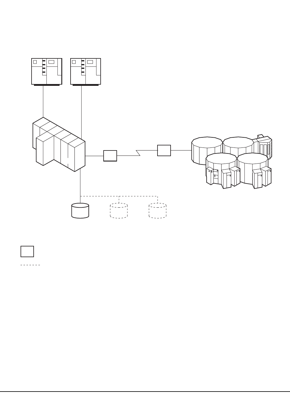
622 VM/HSC 6.0 System Programmer’s Guide
1st ed., 6/30/04 - 312579601
Configuration 1
This configuration consists of one ACS remote-linked to one CPU. The primary,
secondary, and standby control data sets all run on the one CPU.
HSC
OPERATING
SYSTEM
CH
EXT
CH
EXT
CH
EXT
ACS 0
LEGEND:
= CHANNEL EXTENDER
= OPTIONAL C29323
MANUAL TRANSPORTS
SECONDARY
CONTROL
DATA SET
STANDBY
CONTROL
DATA SET
PRIMARY
CONTROL
DATA SET
Figure 29. Configuration 1
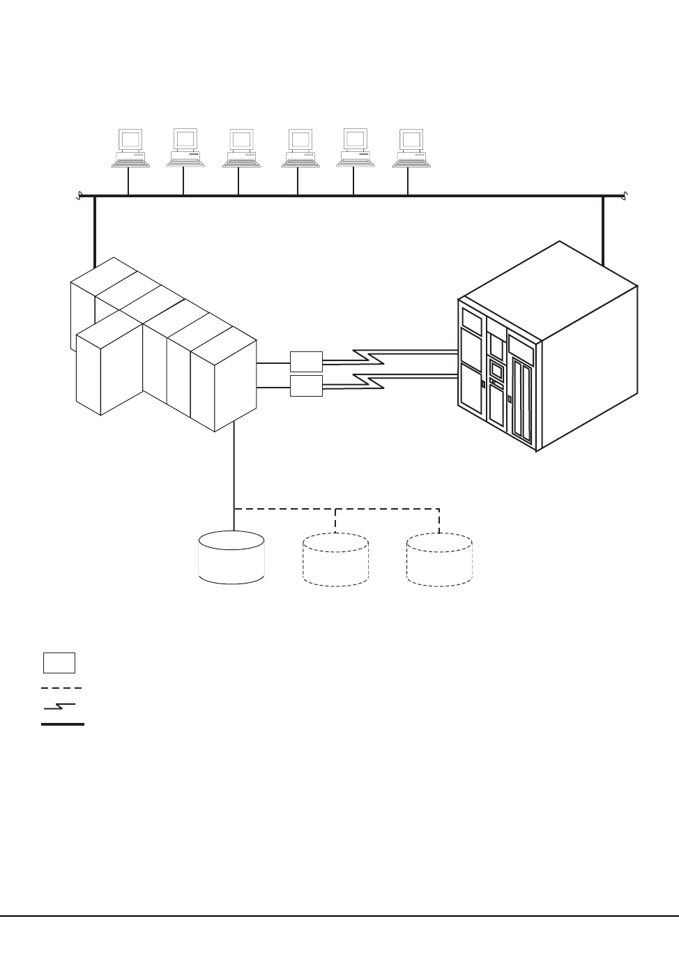
Appendix E. Remote-linked Libraries 623
1st ed., 6/30/04 - 312579601
Configuration 2
This configuration consists of one ACS remote-linked to one CPU. The primary,
secondary, and standby control data sets all run on the one CPU.
Multiple Clients on a Local Area Network
C51183
Primary
Control
Data Set
Data Path
ESCD
TCP/IP Path for Robotic Control
SL8500
Library
Corporate Ethernet
Operating
System
MVS/CSC
HSC/SMC
Secondary
Control
Data Set
Standby
Control
Data Set
ESCD
Legend:
= ESCON Director
= Optional
= Data Path
= Ethernet (TCP/IP)
Data Path
ESCD
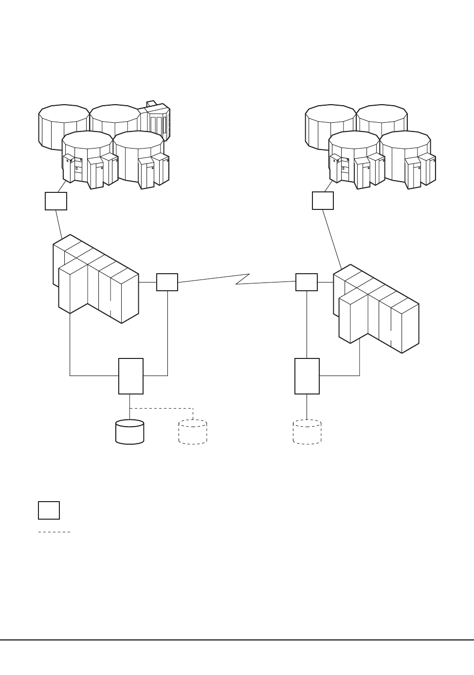
624 VM/HSC 6.0 System Programmer’s Guide
1st ed., 6/30/04 - 312579601
Configuration 3
This configuration consists of one ACS local to one CPU that is remote-linked to another
CPU with one ACS local to it. The primary and secondary control data sets run on
separate SSDs each attached to separate CPUs. The standby control data set can be
attached to either SSD.
LMU LMU
LEGEND:
= CHANNEL EXTENDER
= OPTIONAL
HSC
OPERATING
SYSTEM
OPERATING
SYSTEM
HSC
SSD SSD
ACS 0 ACS 1
C29325
SECONDARY
CONTROL
DATA SET
STANDBY
CONTROL
DATA SET
PRIMARY
CONTROL
DATA SET
CH
EXT
CH
EXT
CH
EXT
Figure 30. Configuration 3
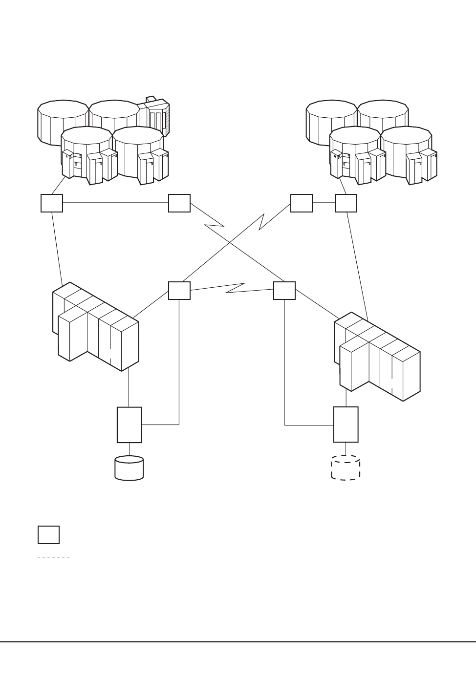
Appendix E. Remote-linked Libraries 625
1st ed., 6/30/04 - 312579601
Configuration 4
This configuration consists of one ACS local to one CPU that is remote-linked to another
CPU with one ACS local to it. The primary and secondary control data sets run on
separate SSDs each attached to separate CPUs.
LEGEND:
= CHANNEL EXTENDER
= OPTIONAL
CH
EXT
LMU LMU
CH
EXT
CH
EXT CH
EXT
CH
EXT
HSC
OPERATING
SYSTEM
OPERATING
SYSTEM
HSC
SSD SSD
ACS 0 ACS 1
C29326
PRIMARY
CONTROL
DATA SET
SECONDARY
CONTROL
DATA SET
Figure 31. Configuration 4
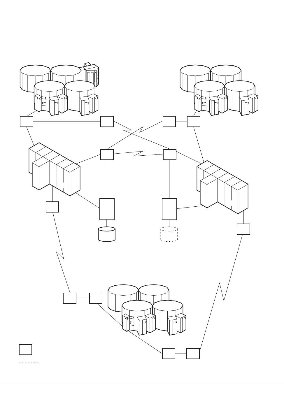
626 VM/HSC 6.0 System Programmer’s Guide
1st ed., 6/30/04 - 312579601
Configuration 5
This configuration consists of one ACS local to one CPU that is remote-linked to another
CPU with one ACS local to it. In addition, a third ACS is remote-linked to both CPUs.
The primary and secondary control data sets run on separate SSDs each attached to
separate CPUs.
LEGEND:
= CHANNEL EXTENDER
=
OPTIONAL
CH
EXT
LMU
LMU
LMU
CH
EXT
CH
EXT
CH
EXT
CH
EXT
CH
EXT
CH
EXT
CH
EXT
CH
EXT
LMU
HSC
OPERATING
SYSTEM
OPERATING
SYSTEM
HSC
SSD SSD
ACS 0
ACS 2
ACS 1
C29327
SECONDARY
CONTROL
DATA SET
PRIMARY
CONTROL
DATA SET
Figure 32. Configuration 5

Appendix E. Remote-linked Libraries 627
1st ed., 6/30/04 - 312579601
Programming and Operational Considerations
The following are programming and operational considerations that should be observed if
you have libraries resembling any of the illustrated configurations. The HSC permits
operation of these library configurations provided that some programming and operational
precautions are observed.
These precautions are based on various functional restrictions described in following
paragraphs. Table 80 lists the functions and the programming precautions that must be
followed for associated configurations.
Resolving CDS Issues After a Remote-Link Failure
In configurations 3, 4, and 5, if there is a failure in the remote link while ACS1 has a
hardware reserve issued against the primary CDS, ACS0 is locked out and is not able to
perform any automated tape services until the reserve is released. This problem can
happen even if the two ACSs are not remote-linked.
The reserve can be released by disabling the remote-link interface. Operator intervention
is required to disable the link.
Restore Involving Journals from Channel-Extended Hosts
In configurations 3, 4, and 5, if a restore of the control data set is needed, and the
journaling option is invoked, all journal files must be obtained from every host that was
included in the library LIBGEN. If all of the journals are not applied when the RESTore
utility is executed, an accurate control data set may not be constructed during the restore
operation.
Obtaining all journals from remote-linked hosts can be a problem if the link is down.
Consequently, not all journals can be obtained to fully satisfy a successful restore of the
control data set.
Careful planning must be done before executing the RESTore utility to ensure that
journals are available from each host and that the remote link is fully operational when the
restore operation is performed.
Control Data Set Integrity
In configurations 3, 4, and 5, the primary control data set and the secondary control data
set are separated across a remote link. If the link is interrupted, the secondary data set
becomes the primary control data set for ACS1.
Table 80. Programming and Operation Precautions for Remote-linked Libraries
Function Applicable Configuration(s)
Resolving CDS issues after a remote-link failure 3 - 5
Restore involving journals from channel extended
hosts
3 - 5
Control data set integrity 3 - 5

628 VM/HSC 6.0 System Programmer’s Guide
1st ed., 6/30/04 - 312579601
The original primary control data set continues to operate for ACS0 only. As the library
operates, any updates occurring to either control data set after the link was severed causes
the data sets to be unsynchronized. It is a difficult task to resynchronize the data for both
data sets.
Possible solutions to resynchronize the data sets include:
• Execute the AUDIt utility and reconcile the differences between the primary control
data set and the secondary data set. This solution is not recommended because of the
time required to perform a full audit operation.
• Execute the BACKup utility, specifying OPTion(Analyze), immediately followed by
the RESTore utility, specifying GENerate(YES). The BACKup utility performs error
and comparison checking of records for the data sets and enables you to reconcile the
differences. With this utility, you can ensure that the two data sets are properly
synchronized. Library operation can be resumed at a high confidence level.
• Prior to reestablishing the link:
1. Bring the HSC down.
2. Reestablish the link.
3. Run BACKup OPTion(Analyze) and RESTore GENerate(YES).
4. Bring the HSC up.
5. Use the discrepancy report produced by the backup to determine discrepancies
between copies of the CDS.
Refer to Chapter 4, “Utility Functions” on page 169 and the AUDIt, BACKup, and
RESTore utilities for detailed information.

Appendix F. Batch Application Program Interface (API) 629
1st ed., 6/30/04 - 312579601
Appendix F. Batch Application Program Interface (API)
Overview
The Batch API allows you to retrieve CDS information in batch mode. The CDS specified
as input to the request does not have to be active nor does it have to be currently
referenced by the HSC address space (the request can execute entirely in the user address
space). In addition, the Batch API executes in the user’s virtual machine, and the HSC
does not have to be active to submit the request.
Note: The HSC CDS must be linked to the virtual machine that is running the Batch API.
QCDS Request
The QCDS request reads records from the input CDS and provides information about
various library elements (e.g., CAPs, drives, volumes, and so forth). QCDS requests are
synchronous, meaning that multiple requests cannot be active at the same time.
QCDS does not interact with the HSC address space except when the request specifies
automatic allocation of the CDS. In this case, the HSC executes a single query operation to
obtain data set information for CDS dynamic allocation. All other request processing
occurs in the user address space. QCDS requests are limited to a single task within the
current job step.
How QCDS Functions
QCDS automatically creates a DCB and opens and closes an input CDS as required. The
request opens the CDS only if no other library element record areas are currently open for
that CDS. Conversely, QCDS closes the CDS only if all other record areas for that CDS
are closed.
Invoking QCDS (SLSUREQ Macro)
QCDS requests are issued by the SLSUREQ macro. Results from the request are returned
in a response area that contains a reply header describing the results and a set of library
element records. The response area must be long enough to contain the reply header and at
least one library element record of the requested type. A read request transfers as many
whole records as possible without exceeding the response area capacity.
Note: To retrieve individual records from the response area, deblock those records using
the record length constant settings provided in the SLUVxDAT record formats. Refer to
“Volume Report and Batch API Records” on page 562 to see these layouts.

630 VM/HSC 6.0 System Programmer’s Guide
1st ed., 6/30/04 - 312579601
The SLSUREQM macro maps the SLSUREQ reply header, parameter list, and return code
values. Refer to “SLSUREQM Macro” on page 645 to see the record layout.
Reply header length is defined in SLSUREQM, and library element record lengths are
defined in the SLUVxDAT macros. Return codes for each request (see “Return Codes” on
page 634) are stored in register 15.
VM Requirement
The program issuing the SLSUREQ macro must include the SLSMAC MACLIB in the
GLOBAL MACLIB definition.
GLOBAL MACLIB SLSMAC...
The SLSMAC MACLIB residing on the HSC run-disk (254) must be available to
assemble the SLSUREQ program.
The SLSUCAL TXTLIB is required to access the SLSUCAL program. The TXTLIB
must be available when needed:
• For the technique where the SLSUCAL is included in the SLSUREQ program
(VCON), the SLSUCAL TXTLIB must be available at CMS command
(LOAD/GENMOD) time.
• When SLSUCAL is loaded using the LOAD macro, the SLSUCAL TXTLIB must be
available at program execution time.
The SLSUCAL TXTLIB must be included in the GLOBAL TXTLIB for both LOAD
options.
GLOBAL TXTLIB SLSUCAL
SLSUREQ VM Requirements
The program issuing the SLSUREQ macro must include the SLSMAC MACLIB in the
GLOBAL MACLIB definition:
GLOBAL MACLIB SLSMAC …
The SLSMAC MACLIB, which resides on HSC RUN-disk 254, must be available to
assemble SLSUREQ.
The SLSUCAL TXTLIB is required to access the SLSUCAL routine.
Addresses and Registers
• RX-type address: specifies an address that is valid in an RX-type instruction.
• Register (2) - (12): indicates that one of the general registers, 2 through 12, should be
specified, enclosed in parentheses. The register must have been previously loaded
with the value required by the parameter. Unused bits must be zeroed.
• Register (13) must point to a 72-byte MVS register save area when a QCDS request
is issued.

Appendix F. Batch Application Program Interface (API) 631
1st ed., 6/30/04 - 312579601
• Register (15): stores QCDS request return codes.
Syntax
The syntax for the QCDS request is:
Parameters
label
label indicates a user-defined assembler label.
REQUEST
request indicates to access a library element record area.
OPEN
specifies to open a library element area and move to the first record of the area.
READ
specifies to retrieve the next group of library element records.
CLOSE
specifies to close a library element area.
This parameter is required.
TYPE
type indicates a library element record area type.
ACS
specifies the ACS/LSM record area
CAP
specifies the CAP record area
CDS
specifies the CDS information record area
CFG
specifies the configuration record area
DRV
specifies the drive record area
label SLSUREQ QCDS ,REQUEST=request ,TYPE=type ,BUFFER=buffer
,BUFLEN=buflen ,TOKEN=token ,DDNAME=ddname ,UCALADR=rtnaddr
,MF=
(E,parmaddr)
L

632 VM/HSC 6.0 System Programmer’s Guide
1st ed., 6/30/04 - 312579601
HST
specifies the host information record area
MVC
specifies the Multi-Volume Cartridge record area
STA
specifies the station record area
VOL
specifies the volume record area
VTV
specifies the Virtual Tape Volume record area
This parameter is required.
BUFFER
buffer indicates an RX-type fullword location or a register (2) - (12) containing the
response area address for this READ request.
This parameter is required for the READ request but is ignored for OPEN and
CLOSE requests.
BUFLEN
buflen indicates an RX-type fullword location or a register (2) - (12) containing the
response area length for this READ request.
This parameter is required for the READ request but is ignored for OPEN and
CLOSE requests.
TOKEN
token indicates an RX-type fullword location or a register (2) - (12) containing a
fullword address that maintains QCDS state information for an input CDS.
The token value for an OPEN request must be zero when no associated CDS record
areas are open. In this case, OPEN assigns a value to token that must be presented
with all other QCDS requests for that CDS.
When all record areas of the CDS are closed, the token is no longer valid.
This parameter is required.
DDNAME
ddname indicates an RX-type address or a register (2) - (12) containing the address
of the eight-character DDname of an input CDS. A DDname less than eight
characters must be padded with trailing blanks.

Appendix F. Batch Application Program Interface (API) 633
1st ed., 6/30/04 - 312579601
Notes:
1. A CDS must be preallocated to ddname in the JCL or in a SVC 99 dynamic
allocation request before issuing QCDS requests.
2. The input CDS does not need to be active or referenced by the HSC address
space.
3. QCDS allows for multiple input CDSs, as long as each uses a unique ddname
and specifies a different token for each open CDS. For example, an application
can open two input CDSs and process them in an alternating, or interleaved,
fashion.
This parameter is optional. If DDNAME is omitted, QCDS attempts to open the
most recently updated CDS specified in the SLSCNTL, SLSCNTL2, or SLSSTBY
DDnames for the current job step. If none of these DDnames is defined, QCDS tries
to open an active CDS. In this case, the HSC address space must be active or the
OPEN fails.
UCALADR
rtnaddr indicates an RX-type fullword location, register (15), or a register (2) - (12)
containing the address of the SLSUCAL routine.
This parameter is required. You must load the SLSUCAL module into storage
before issuing a QCDS request.
MF
indicates either the list or execute form of the macro.
L
specifies the list form of the macro. This parameter generates a remote
parameter list that can be referenced by the execute form of the macro.
Note: When L is specified, all other parameters are ignored.
E,parmaddr
specifies the execute form of the macro. parmaddr is an RX-type address or a
register (1) - (12) containing the address of the remote parameter list.
This parameter is required.
QCDS Programming Considerations
• Only one instance of each library element record area can be open for each
invocation.
• QCDS does not account for CDS switches for any open input CDS.
• The job step or task should define DDname SYSMDUMP to capture diagnostic
information if an internal QCDS error occurs.
• Record order within a library element record area is unpredictable.

634 VM/HSC 6.0 System Programmer’s Guide
1st ed., 6/30/04 - 312579601
Return Codes
Invalid SLSUREQ requests and QCDS access requests provide return codes in register 15.
Table 80 shows the list of return codes.
Table 81. Batch API Return Codes
Return Field Name: Decimal Value and Description:
Invalid SLSUREQ Requests:
SLURRQPL 1000 - SLSUREQ request failed: Invalid SLSUREQ
parameter list.
SLURRQRT 1001 - SLSUREQ request failed: Invalid SLSUREQ request
type.
SLURQCRT 1002 - SLSUREQ request failed: Invalid QCDS access
request type.
OPEN Return Codes:
SLUROPOK 0 - Record area was opened successfully.
SLUROPAO 4 - Open failed: Attempt to open a record area that is already
open.
SLUROPIT 8 - Open failed: Invalid token value.
SLUROPRA 12 - Open failed: Invalid record area type.
SLUROPIO 16 - Open failed: I/O error while accessing the associated
CDS.
SLUROPDD 20 - Open failed: An input CDS is not allocated to the
designated DDname.
SLUROPNA 24 - Open failed: HSC address space not operational during
automatic CDS allocation attempt.
SLUROPDA 28 - Open failed: Error during automatic CDS dynamic
allocation operation.
READ Return Codes:
SLURRDOK 0 - Successful read. One or more records were transferred to
the response area and one or more additional records can be
obtained by a subsequent READ request.
SLURRDEA 4 - Successful read. One or more records were transferred to
the response area and no additional records can be read from
the associated record area.
SLURRDIT 8 - Read failed: Invalid token value.
SLURRDRA 12 - Read failed: Invalid record area type.
SLURRDIO 16 - Read failed: I/O error while accessing the associated
CDS.
SLURRDNO 20 - Read failed: Attempt to read a record area that is not
currently open.

Appendix F. Batch Application Program Interface (API) 635
1st ed., 6/30/04 - 312579601
Sample QCDS Requests
The following QCDS program samples detail two different scenarios:
• a request to open the current primary CDS
• a request to process two library element record area types.
Both of these examples can be found in the SAMPLIB data set distributed to customers.
Error processing code has been omitted in the examples.
Sample 1 - Reading the Volume Record Area of the Current Primary CDS
This sample QCDS request uses automatic CDS allocation to open the current primary
CDS. Automatic CDS allocation does not require JCL to identify the input CDS but does
require an operational HSC address space.
After opening the CDS volume record area, the program reads groups of volume records
into a 64 KB response area buffer.
SLURRDBA 24 - Read failed: Attempt to read beyond the end of the
record area.
SLURRDIB 28 - Read failed: Invalid response area buffer address.
SLURRDIL 32 - Read failed: Response area buffer length too short to
contain both the reply header and at least one library element
record.
CLOSE Return Codes:
SLURCLOK 0 - Record area was closed successfully.
SLURCLAC 4 - Close failed: Attempt to close a record area that is
already closed.
SLURCLIT 8 - Close failed: Invalid token value.
SLURCLRA 12 - Close failed: Invalid record area type.
SLURCLIO 16 - Close failed: I/O error while accessing the associated
CDS.
Table 81. Batch API Return Codes (Continued)
Return Field Name: Decimal Value and Description:

636 VM/HSC 6.0 System Programmer’s Guide
1st ed., 6/30/04 - 312579601
QCDSVTV TITLE 'QCDS Read current primary CDS VTV record area'
*
*
* Function: Use QCDS to automatically allocate and Open the
* current primary CDS. Issue SLSUREQ QCDS requests to
* read all the VTV records.
*
* Attributes:
* 1. Problem state, user key.
* 2. Non-APF authorized.
* 3. AMODE 24, RMODE 24 (for below-the-line QSAM), reentrant.
*
* Notes:
* The caller must have read access for the current primary
* CDS.
*
**ENDPROLOGUE*****************************************************
PRINT GEN
ENTRY QCDSVTV
QCDSVTV CSECT
QCDSVTV AMODE 24 Below the line for QSAM (PUT macro).
QCDSVTV RMODE 24
*
* Save the caller's registers, establish CSECT addressability
* and create the module work area:
*
STM R14,R12,12(R13) Save registers
LR R12,R15 Load base register R12
USING QCDSVTV,R12 Declare CSECT base register R12
GETMAIN R,LV=WKAREAL Allocate module work area
ST R13,WKSAVE-WKAREA+4(,R1) Link new save area to old one
ST R1,8(,R13) Link old save area to new one
LR R13,R1 Pointer to module work area
USING WKAREA,R13 Addressability to module work area
*
* Load module SLSUCAL:
*
LOAD EP=SLSUCAL Load SLSUCAL into storage
ST R0,WKUCAL Save SLSUCAL routine address
*
* Initialize the QCDS token and the SLSUREQ plist:
*
XC WKTOK,WKTOK QCDS token initially zero
LA R0,WKQCDS Pointer to SLSUREQ plist storage
LA R1,QCDSMLEN Length of SLSUREQ plist
LA R14,QCDSMODL Pointer to SLSUREQ plist model
LR R15,R1 Length of SLSUREQ plist model
MVCL R0,R14 Initialize SLSUREQ plist storage
*
Figure 33. Sample 1 - Automatic CDS Allocation
(1 of 4)

Appendix F. Batch Application Program Interface (API) 637
1st ed., 6/30/04 - 312579601
MVC WKFLATDD(KFLATDDL),KFLATDD Initialize the working
LA R4,WKFLATDD storage version of the DCB from the
OPEN ((R4),(OUTPUT)) copy in the constants area.
*
* Use QCDS OPEN to automatically allocate the current primary CDS
* and open the VTV record area:
*
OPENVOL DS 0H Open CDS VTV record area:
SLSUREQ QCDS, +
REQUEST=OPEN, +
DDNAME==CL8'CDS1', +
TYPE=VTV, +
TOKEN=WKTOK, +
UCALADR=WKUCAL, +
MF=(E,WKQCDS)
C R15,=A(SLUROPOK) Check for OPEN failure
BNE OPENERR Handle OPEN error
*
* Allocate response area buffer and map the response area:
*
L R0,QCDSBLEN Load response area buffer length
GETMAIN R,LV=(0) Request storage
ST R1,WKBUFP Store pointer to response area
LR R10,R1 Load pointer to response area
USING SLUR,R10 Map QCDS READ response area
*
* Outer loop - read CDS VTV record area in blocks:
*
READVOL DS 0H Read block of VTV records:
SLSUREQ QCDS, +
REQUEST=READ, +
DDNAME==CL8'CDS1', +
TYPE=VTV, +
BUFFER=WKBUFP, +
BUFLEN=QCDSBLEN, +
TOKEN=WKTOK, +
UCALADR=WKUCAL, +
MF=(E,WKQCDS)
ST R15,WKRDRC Save READ return code
C R15,=A(SLURRDEA) Check for READ failure
BH READERR Handle READ error
L R9,SLURQCDN Get number of VTV records
* present in this reply
L R7,SLURQCDO Offset to first VTV record
LA R8,SLURRPLY(R7) Pointer to first VTV record
USING SLUVTDAT,R8 Map VTV record
*
Figure 33. Sample 1 - Automatic CDS Allocation
(2 of 4)

638 VM/HSC 6.0 System Programmer’s Guide
1st ed., 6/30/04 - 312579601
* Inner loop - process each VTV record in the response area:
*
VOLPROC DS 0H Over all VTV records in reply:
* ... process VTV record here ...
PUT WKFLATDD,((R8))
LA R8,VDRECLEN(,R8) Pointer to next VTV record
BCT R9,VOLPROC Process next VTV record
CHECKEOA DS 0H Check for more VTV records
CLC WKRDRC,=A(SLURRDEA) VTV end-of-area?
BNE READVOL No, read more VTV records
*
* Close the CDS VTV record area:
*
CLOSEVOL DS 0H Close VTV record area:
LA R4,WKFLATDD
CLOSE ((R4))
SLSUREQ QCDS, +
REQUEST=CLOSE, +
DDNAME==CL8'CDS1', +
TYPE=VTV, +
TOKEN=WKTOK, +
UCALADR=WKUCAL, +
MF=(E,WKQCDS)
LTR R15,R15 Check for CLOSE failure
BNZ CLOSEERR Handle CLOSE error
B EXIT
READERR WTO 'READ ERROR'
B EXIT
CLOSEERR WTO 'CLOSE ERROR'
B EXIT
*
* Clean up and return to caller:
*
OPENERR WTO 'OPEN ERROR'
EXIT DS 0H Clean up and return to caller:
DELETE EP=SLSUCAL Unload SLSUCAL routine
L R0,QCDSBLEN Load response area length
L R1,WKBUFP Pointer to response area
FREEMAIN R,A=(R1),LV=(R0) Release response area buffer
LR R1,R13 Pointer to module work area
L R13,4(,R13) Restore caller's save area pointer
FREEMAIN R,A=(R1),LV=WKAREAL Release module work area
L R14,12(,R13) Restore return address
LM R0,R12,20(R13) Restore caller's registers 0-12
XR R15,R15 Set return code zero
BR R14 Return to caller
*
Figure 33. Sample 1 - Automatic CDS Allocation
(3 of 4)

Appendix F. Batch Application Program Interface (API) 639
1st ed., 6/30/04 - 312579601
* Constants:
*
QCDSMODL SLSUREQ MF=L SLSUREQ plist model
QCDSMLEN EQU *-QCDSMODL Length of SLSUREQ plist model
QCDSBLEN DC F'655360' QCDS READ response area buffer length
KFLATDD DCB DDNAME=VDRECDAT,DSORG=PS,MACRF=(PM), +
LRECL=VDRECLEN, +
BLKSIZE=VDRECLEN*100,RECFM=FB
KFLATDDL EQU *-KFLATDD
*
* Module work area map:
*
WKAREA DSECT Module work area
WKSAVE DS 18F MVS register save area
WKUCAL DS A SLSUCAL routine address
WKTOK DS F QCDS request token
WKRDRC DS F QCDS READ return code
WKBUFP DS A QCDS READ response area buffer addr
WKQCDS DS XL(QCDSMLEN) SLSUREQ plist storage
WKFLATDD DS XL(KFLATDDL)
WKAREAL EQU *-WKAREA Length of module work area
*
* Mapping macros:
*
SLSREGS , Register equates
SLSUREQM , SLSUREQ mapping macro
SLUVTDAT , VTV record mapping macro
END QCDSVTV
Figure 33. Sample 1 - Automatic CDS Allocation
(4 of 4)

640 VM/HSC 6.0 System Programmer’s Guide
1st ed., 6/30/04 - 312579601
Sample 2 - Reading the ACS and DRV Record Areas Together
This sample QCDS request reads two different CDS record areas (ACS and DRV),
alternating between the two. The job step JCL must include a DDNAME statement for the
input CDS DDname (MVS1CDS in this example).

Appendix F. Batch Application Program Interface (API) 641
1st ed., 6/30/04 - 312579601
QACSDRV TITLE ‘QCDS READ ACS AND DRIVE RECORD AREAS TOGETHER’
*
* QACSDRV ! QCDS READ ACS AND DRIVE RECORD AREAS TOGETHER.
*
* FUNCTION: USE SEPARATE RESPONSE AREAS TO READ THE ACS AND DRV
* RECORD AREAS IN AN ALTERNATING FASHION.
* EACH RESPONSE AREA IS A 1KB BUFFER.
*
* ATTRIBUTES:
* 1. PROBLEM STATE, USER KEY.
* 2. NON!APF AUTHORIZED.
* 3. AMODE 31, RMODE ANY, REENTRANT.
*
* NOTES:
* THE CALLER MUST HAVE READ ACCESS FOR THE INPUT CDS.
*
**ENDPROLOGUE*****************************************************
PRINT GEN
ENTRY QACSDRV
QACSDRV CSECT
QACSDRV AMODE 31
QACSDRV RMODE ANY
*
* SAVE THE CALLER’S REGISTERS, ESTABLISH CSECT ADDRESSABILITY
* AND ESTABLISH NEW REGISTER SAVE AREA:
*
STM R14,R12,12(R13) SAVE REGISTERS
LR R12,R15 LOAD BASE REGISTER R12
USING QACSDRV,R12 DECLARE CSECT BASE REGISTER R12
GETMAIN R,LV=WKAREAL ALLOCATE MODULE WORK AREA
ST R13,WKSAVE!WKAREA+4(,R1) LINK NEW SAVE AREA TO OLD ONE
ST R1,8(,R13) LINK OLD SAVE AREA TO NEW ONE
LR R13,R1 POINTER TO MODULE WORK AREA
USING WKAREA,R13 ADDRESSABILITY TO MODULE WORK AREA
*
* LOAD MODULE SLSUCAL:
*
LOAD EP=SLSUCAL LOAD SLSUCAL INTO STORAGE
ST R0,WKUCAL SAVE SLSUCAL ROUTINE ADDRESS
*
* INITIALIZE THE QCDS TOKEN AND THE SLSUREQ PLIST:
*
XC WKTOK,WKTOK QCDS TOKEN INITIALLY ZERO
LA R0,WKQCDS POINTER TO SLSUREQ PLIST STORAGE
LA R1,QCDSMLEN LENGTH OF SLSUREQ PLIST
LA R14,QCDSMODL POINTER TO SLSUREQ PLIST MODEL
LR R15,R1 LENGTH OF SLSUREQ PLIST MODEL
MVCL R0,R14 INITIALIZE SLSUREQ PLIST STORAGE
Figure 34. Sample 2 - Reading ACS and DRV Together
(1 of 4)

642 VM/HSC 6.0 System Programmer’s Guide
1st ed., 6/30/04 - 312579601
*
* OPEN ACS AND DRIVE RECORD AREAS AND MAP THE RESPONSE AREAS:
*
OPEN DS 0H OPEN ACS AND DRIVE RECORD AREAS:
SLSUREQ QCDS, OPEN ACS RECORD AREA
REQUEST=OPEN,
TYPE=ACS,
TOKEN=WKTOK,
DDNAME=QCDSDD,
UCALADR=WKUCAL,
MF=(E,WKQCDS)
SLSUREQ QCDS, OPEN DRIVE RECORD AREA
REQUEST=OPEN,
TYPE=DRV,
TOKEN=WKTOK,
UCALADR=WKUCAL,
MF=(E,WKQCDS)
USING SLUR,R9 MAP QCDS READ RESPONSE AREA
*
* MAIN PROCESSING LOOP ! INTERLEAVED PROCESSING OF ACS AND
* DRIVE RECORDS:
*
PROCESS DS 0H MAIN PROCESSING LOOP:
LA R9,WKACSBUF POINTER TO ACS RESPONSE AREA
SLSUREQ QCDS, READ ACS RECORD AREA
REQUEST=READ,
TYPE=ACS,
BUFFER=(R9),
BUFLEN=QCDSBLEN,
TOKEN=WKTOK,
UCALADR=WKUCAL,
MF=(E,WKQCDS)
L R7,SLURQCDO OFFSET TO FIRST ACS RECORD
LA R11,SLURRPLY(R7) POINTER TO FIRST ACS RECORD
USING SLUVADAT,R11 MAP ACS RECORD FORMAT
*
* ... PROCESS ACS RECORDS ...
*
LA R9,WKDRVBUF POINTER TO DRIVE RESPONSE AREA
SLSUREQ QCDS, READ DRIVE RECORD AREA
REQUEST=READ,
TYPE=DRV,
BUFFER=(R9),
BUFLEN=QCDSBLEN,
TOKEN=WKTOK,
UCALADR=WKUCAL,
MF=(E,WKQCDS)
L R7,SLURQCDO OFFSET TO FIRST DRIVE RECORD
LA R10,SLURRPLY(R7) POINTER TO FIRST DRIVE RECORD
USING SLUVDDAT,R10 MAP DRIVE RECORD FORMAT
*
* ... PROCESS DRIVE RECORDS ...
Figure 34. Sample 2 - Reading ACS and DRV Together
(2 of 4)

Appendix F. Batch Application Program Interface (API) 643
1st ed., 6/30/04 - 312579601
*
* CONDITIONALLY BRANCH TO CLOSE LABEL WHEN AN APPROPRIATE
* LOOP TERMINATION CONDITION HAS BEEN SATISFIED (NOT SHOWN).
*
B PROCESS REPEAT MAIN PROCESSING LOOP
*
* CLOSE THE ACS AND DRIVE RECORD AREAS:
*
CLOSE DS 0H CLOSE ACS AND DRIVE RECORD AREAS:
SLSUREQ QCDS, CLOSE THE ACS RECORD AREA
REQUEST=CLOSE,
TYPE=ACS,
TOKEN=WKTOK,
UCALADR=WKUCAL,
MF=(E,WKQCDS)
SLSUREQ QCDS, CLOSE THE DRIVE RECORD AREA
REQUEST=CLOSE,
TYPE=DRV,
TOKEN=WKTOK,
UCALADR=WKUCAL,
MF=(E,WKQCDS)
*
* CLEAN UP AND RETURN TO CALLER:
*
EXIT DS 0H CLEAN UP AND RETURN TO CALLER:
DELETE EP=SLSUCAL UNLOAD SLSUCAL ROUTINE
LR R1,R13 POINTER TO MODULE WORK AREA
L R13,4(,R13) RESTORE CALLER’S SAVE AREA
FREEMAIN R,A=(R1),LV=WKAREAL RELEASE MODULE WORK AREA
L R14,12(,R13) RESTORE RETURN ADDRESS
LM R0,R12,20(R13) RESTORE CALLER’S REGISTERS 0!12
XR R15,R15 SET ZERO RETURN CODE
BR R14 RETURN TO CALLER
*
* CONSTANTS:
*
QCDSMODL SLSUREQ MF=L SLSUREQ PLIST MODEL
QCDSMLEN EQU *!QCDSMODL LENGTH OF SLSUREQ PLIST MODEL
QCDSDD DC CL8’MVS1CDS ‘ 8!CHAR BLANK!PADDED CDS DDNAME
QCDSBLEN DC F’1024’ QCDS READ RESPONSE AREA BUFFER LENGTH
*
* MODULE WORK AREA MAP:
*
WKAREA DSECT MODULE WORK AREA
WKSAVE DS 18F MVS REGISTER SAVE AREA
WKUCAL DS A SLSUCAL ROUTINE ADDRESS
WKTOK DS F QCDS REQUEST TOKEN
WKQCDS DS XL(QCDSMLEN) SLSUREQ PLIST STORAGE
WKACSBUF DS XL1024 ACS RESPONSE AREA BUFFER
WKDRVBUF DS XL1024 DRV RESPONSE AREA BUFFER
WKAREAL EQU *!WKAREA LENGTH OF MODULE WORK AREA
Figure 34. Sample 2- Reading ACS and DRV Together
(3 of 4)

644 VM/HSC 6.0 System Programmer’s Guide
1st ed., 6/30/04 - 312579601
Output Description
Each successful OPEN request returns the name of the input CDS in the SLSUREQ
parameter list (SLSUREQM field SLSUQDSN).
Each successful READ request returns one or more library element records in the
user-designated response area. Use the SLUR DSECT in the SLSUREQM macro to map
the response area reply header. This header contains the number of library element records
present within the response area.
Library element records are mapped by the SLUVxDAT macros. These macros are
SMP-distributed and are discussed in “Volume Report and Batch API Mapping Macros”
on page 562.
Table 82. Library Element Record Mapping
Request Entered: Records Returned:
READ ACS ACS/LSM records mapped by SLUVADAT macro.
READ CAP CAP records mapped by SLUVPDAT macro.
READ CDS CDS information records mapped by SLUVIDAT macro.
READ CFG Configuration information records mapped by SLUVCDAT
macro.
READ DRV Drive records mapped by the SLUVDDAT macro.
READ HST Host information records mapped by the SLUVHDAT macro.
READ STA Station records mapped by the SLUVSDAT macro.
READ VOL Volume records mapped by the SLUVVDAT macro.
*
* MAPPING MACROS:
*
SLSREGS REGISTER
EQUATES
SLSUREQM , SLSUREQ
MAPPING MACRO
SLUVADAT , ACS
Figure 34. Sample 2 - Reading ACS and DRV Together
(4 of 4)

Appendix F. Batch Application Program Interface (API) 645
1st ed., 6/30/04 - 312579601
SLSUREQM Macro
The SLSUREQM mapping macro must be specified in any assembly that uses the
SLSUREQ macro.
Syntax
Parameters
PRO={NO|YES}
Specifies whether the prologue should be generated (YES) or not (NO). The default
is NO.
label SLSUREQM
PRO=
NO
YES

646 VM/HSC 6.0 System Programmer’s Guide
1st ed., 6/30/04 - 312579601
Batch API Mapping (SLSUREQM) Macro
Table 83. SLSUREQM Record Format
Dec Hex Type Length Label Description
MACRO: SLSUREQM - BATCH API USER INTERFACE MAPPING MACRO
FUNCTION:
THIS MACRO MAPS THE SLSUCAL PARAMETER LIST, REPLY HEADER,
AND RETURN CODES.
0 (0) STRUCTURE SLSUREQM PARAMETER LIST
0 (0) CHARACTER 4 SLSUHDR EYE-CATCHER FIELD:
‘SLSU’ (E2D3E2E4) CHAR CONST SLSUID EYE-CATCHER VALUE
4 (4) A-ADDR 1 SLSUVER VERSION OF SLSUREQ:
4(04) CONST SLSUVN CURRENT VERSION
5 (5) A-ADDR 1 SLSURT REQUEST TYPE:
1 (01) CONST SLSUQCDS QCDS REQUEST
6 (6) A-ADDR 1 SLSUQCDT QCDS REQUEST TYPE:
0 (00) CONST SLSUQCDO OPEN REQUEST
1 (01) CONST SLSUQCDR READ REQUEST
2 (02) CONST SLSUQCDC CLOSE REQUEST
7 (7) A-ADDR 1 SLSUQCDA QCDS RECORD AREA:
0 (00) CONST SLSUACSA ACS RECORD AREA
1 (01) CONST SLSUCAPA CAP RECORD AREA
2 (02) CONST SLSUCDSA CDS RECORD AREA
3 (03) CONST SLSUCFGA CONFIGURATION RECORD
AREA
4 (04) CONST SLSUDRVA DRIVE RECORD AREA
5 (05) CONST SLSUHSTA HOST RECORD AREA
6 (06) CONST SLSUSTAA STATION RECORD AREA
7 (07) CONST SLSUVOLA VOLUME RECORD AREA
8(08) CONST SLSUMVCA MVC RECORD AREA
9(09) CONST SLSUVTVA VTV RECORD AREA
10 (0A) CONST SLSUARAN ABSOLUTE RECORD AREA
NUMBER USED WHEN
ALLOCATING STORAGE.
8 (8) A-ADDR 4 SLSUQCDK QCDS TOKEN POINTER

Appendix F. Batch Application Program Interface (API) 647
1st ed., 6/30/04 - 312579601
12 (C) A-ADDR 4 SLSUQCDB QCDS RESPONSE AREA
BUFFER ADDRESS
16 (10) SIGNED-FWORD 4 SLSUQCDL QCDS RESPONSE AREA
BUFFER LENGTH
20 (14) A-ADDR 4 SLSUQCDD QCDS INPUT CDS
DDNAME POINTER
24 (18) CHARACTER 44 SLSUQDSN QCDS INPUT CDS DATA
SET NAME
68 (44) CHARACTER 256 -RESERVED- RESERVED FOR FUTURE
PARM EXPANSION
328 (148) AREA 8 -RESERVED- ALIGNMENT
328 (148) LENGTH SLSULN LENGTH OF FIXED AREA
OF SLSUREQM
SLSUREQ INVOCATION FAILURE RETURN CODES:
1000 (3E8) CONST SLURRQPL SLSUREQ REQUEST
FAILED: INVALID
SLSUREQ PARAMETER
LIST.
1001 (3E9) CONST SLURRQRT SLSUREQ REQUEST
FAILED: INVALID
SLSUREQ UTILITY
REQUEST TYPE.
1002 (3EA) CONST SLURQCRT SLSUREQ REQUEST
FAILED: INVALID QCDS
ACCESS REQUEST TYPE.
SLSUREQ RESPONSE AREA:
0 (0) STRUCTURE SLUR RESPONSE AREA
0 (0) AREA 1 SLURRPLY START OF REPLY HEADER
0 (0) CHARACTER 4 SLURHDR EYE-CATCHER FIELD:
‘SLUR’ (E2D3E4D9) CHAR CONST SLURID EYE-CATCHER VALUE
4 (4) SIGNED-HWORD 2 SLURHSCV HSC VERSION NUMBER
6(6) HEXSTRING 1 SLURVER VERSION NUMBER OF
SLSUREQM
7(7) HEXSTRING 1 -RESERVED- ****** RESERVED *******
8 (8) SIGNED-FWORD 4 SLURQCDN NUMBER OF QCDS
LIBRARY ELEMENT
RECORDS PRESENT IN
THIS REPLY.
Table 83. SLSUREQM Record Format (Continued)
Dec Hex Type Length Label Description

648 VM/HSC 6.0 System Programmer’s Guide
1st ed., 6/30/04 - 312579601
12 (C) SIGNED-FWORD 4 SLURQCDO OFFSET TO QCDS
LIBRARY ELEMENT
RECORD SECTION FROM
START OF REPLY HEADER.
QCDS OPEN RETURN
CODES:
0 (00) CONST SLUROPOK RECORD AREA WAS
OPENED SUCCESSFULLY.
4 (04) CONST SLUROPAO OPEN FAILED - ATTEMPT
TO OPEN A RECORD AREA
THAT IS ALREADY OPEN.
8 (08) CONST SLUROPIT OPEN FAILED - INVALID
TOKEN VALUE.
12 (0C) CONST SLUROPRA OPEN FAILED - INVALID
RECORD AREA TYPE.
16 (10) CONST SLUROPIO OPEN FAILED - I/O ERROR
WHILE ACCESSING THE
ASSOCIATED CDS.
20 (14) CONST SLUROPDD OPEN FAILED - AN INPUT
CDS IS NOT ALLOCATED
TO THE DESIGNATED
DDNAME.
24 (18) CONST SLUROPNA OPEN FAILED - HSC
ADDRESS SPACE NOT
OPERATIONAL DURING
AUTOMATIC CDS
ALLOCATION ATTEMPT.
28 (1C) CONST SLUROPDA OPEN FAILED - ERROR
DURING AUTOMATIC CDS
DYNAMIC ALLOCATION
OPERATION.
32 (20) CONST SLUROPDM OPEN FAILED - DD
PARAMETER MISSING
QCDS READ RETURN CODES:
0 (00) CONST SLURRDOK READ SUCCEEDED - ONE
OR MORE RECORDS WERE
TRANSFERRED TO THE
RESPONSE AREA AND
ONE OR MORE
ADDITIONAL RECORDS
CAN BE OBTAINED BY A
SUBSEQUENT READ
REQUEST.
Table 83. SLSUREQM Record Format (Continued)
Dec Hex Type Length Label Description

Appendix F. Batch Application Program Interface (API) 649
1st ed., 6/30/04 - 312579601
4 (04) CONST SLURRDEA READ SUCCEEDED - ONE
OR MORE RECORDS WERE
TRANSFERRED TO THE
RESPONSE AREA AND NO
ADDITIONAL RECORDS
CAN BE READ FROM THE
ASSOCIATED RECORD
AREA.
8 (08) CONST SLURRDIT READ FAILED - INVALID
TOKEN VALUE.
12 (0C) CONST SLURRDRA READ FAILED - INVALID
RECORD AREA TYPE.
16 (10) CONST SLURRDIO READ FAILED - I/O ERROR
WHILE ACCESSING THE
ASSOCIATED CDS.
20 (14) CONST SLURRDNO READ FAILED - ATTEMPT
TO READ A RECORD AREA
THAT IS NOT CURRENTLY
OPEN.
24 (18) CONST SLURRDBA READ FAILED - ATTEMPT
TO READ BEYOND THE
END OF THE RECORD
AREA.
28 (1C) CONST SLURRDIB READ FAILED - INVALID
RESPONSE AREA BUFFER
ADDRESS.
32 (20) CONST SLURRDIL READ FAILED - RESPONSE
AREA BUFFER LENGTH
TOO SHORT TO CONTAIN
BOTH THE REPLY HEADER
AND AT LEAST ONE
LIBRARY ELEMENT
RECORD.
QCDS CLOSE RETURN CODES:
0 (00) CONST SLURCLOK RECORD AREA WAS
CLOSED SUCCESSFULLY.
4 (04) CONST SLURCLAC CLOSE FAILED - ATTEMPT
TO CLOSE A RECORD
AREA THAT IS ALREADY
CLOSED.
8(08) CONST SLURCLIT CLOSE FAILED - INVALID
TOKEN VALUE.
12 (0C) CONST SLURCLRA CLOSE FAILED - INVALID
RECORD AREA TYPE.
Table 83. SLSUREQM Record Format (Continued)
Dec Hex Type Length Label Description

650 VM/HSC 6.0 System Programmer’s Guide
1st ed., 6/30/04 - 312579601
16 (10) CONST SLURCLIO CLOSE FAILED - I/O
ERROR WHILE
ACCESSING THE
ASSOCIATED CDS.
16 (10) LENGTH SLURRHLN LENGTH OF REPLY
HEADER.
16 (10) AREA 4 SLURFRS START OF
VARIABLE-LENGTH
FORMATTED RECORD
SEGMENT.
Table 83. SLSUREQM Record Format (Continued)
Dec Hex Type Length Label Description

Appendix F. Batch Application Program Interface (API) 651
1st ed., 6/30/04 - 312579601
Cross Reference
Name Len
Offset
Value
SLSUACSA - 00
SLSUARAN - 0A
SLSUCAPA - 01
SLSUCDSA - 02
SLSUCFGA - 03
SLSUDRVA - 04
SLSUHDR 000004 00
SLSUHSTA - 05
SLSUID - ‘CVAL’
SLSULN - 148
SLSUMVCA - 08
SLSUQCDA 000001 07
SLSUQCDB 000004 0C
SLSUQCDC - 02
SLSUQCDD 000004 14
SLSUQCDK 000004 08
SLSUQCDL 000004 10
SLSUQCDO - 00
SLSUQCDR - 01
SLSUQCDS - 01
SLSUQCDT 000001 06
SLSUQDSN 000044 18
SLSURT 000001 05
SLSUSTAA - 06
SLSUVER 000001 04
SLSUVN - 04
SLSUVOLA - 07
SLSUVTVA - 09
SLURCLAC - 04
SLURCLIO - 10
SLURCLIT - 08

652 VM/HSC 6.0 System Programmer’s Guide
1st ed., 6/30/04 - 312579601
SLURCLOK - 00
SLURCLRA - 0C
SLURFRS 000004 10
SLURHDR 000004 00
SLURHSCV 000002 04
SLURID - ‘CVAL’
SLUROPAO - 04
SLUROPDA - 1C
SLUROPDD - 14
SLUROPDM - 20
SLUROPIO - 10
SLUROPIT - 08
SLUROPNA - 18
SLUROPOK - 00
SLUROPRA - 0C
SLURQCDN 000004 08
SLURQCDO 000004 0C
SLURQCRT - 3EA
SLURRDBA - 18
SLURRDEA - 04
SLURRDIB - 1C
SLURRDIL - 20
SLURRDIO - 10
SLURRDIT - 08
SLURRDNO - 14
SLURRDOK - 00
SLURRDRA - 0C
SLURRHLN - 10
SLURRPLY 000001 00
SLURRQPL - 3E8
SLURRQRT - 3E9
SLURVER 000001 06
Name Len
Offset
Value

Appendix F. Batch Application Program Interface (API) 653
1st ed., 6/30/04 - 312579601

654 VM/HSC 6.0 System Programmer’s Guide
1st ed., 6/30/04 - 312579601

Glossary 655
1st ed., 6/30/04 - 312579601
Glossary
Terms are defined as they are used in the text. If you
cannot find a term here, check the index.
A
AC— Alternating current.
access method— A technique for moving data
between processor storage and I/O devices.
ACS— See Automated Cartridge System.
ACSid— An ACSid (acs-id) is a hexadecimal value
from 00 through FF that identifies the LMU. An
ACSid is the result of defining the SLIALIST macro
during the library generation (LIBGEN) process. The
first ACS listed in this macro acquires a hexadecimal
identifier of 00, the second acquires a hexadecimal
identifier of 01, and so forth, until all ACSs are
identified.
allocation— The selection of a cartridge drive, either
inside the library or outside (by the HSC software for
HSC allocation, or MVS for MVS allocation without
the HSC).
APF— Authorized Program Facility.
APPL— VTAM APPLID definition for the HSC.
archiving— The storage of backup files and
associated journals, usually for a given period of
time.
Automated Cartridge System (ACS)— The library
subsystem consisting of one or two LMUs, and from
1 to 16 attached LSMs.
automated library— See library.
automatic mode— A relationship between an LSM
and all attached hosts. LSMs operating in automatic
mode handle cartridges without operator
intervention. This is the normal operating mode of an
LSM that has been modified online.
B
basic direct access method (BDAM)— An access
method used to directly retrieve or update particular
blocks of a data set on a direct access device.
basic sequential access method (BSAM)— An
access method for storing and retrieving data blocks
in a continuous sequence, using either a sequential
access or direct access device.
BDAM— See Basic direct access method.
beginning-of-tape (BOT)— The location on a tape
where written data begins.
block— A collection of contiguous records recorded
as a unit. Blocks are separated by interblock gaps,
and each block may contain one or more records.
BOT— See beginning-of-tape.
BSAM— See Basic Sequential Access Method.
buffer— A routine or storage used to compensate for
a difference in rate of data flow, or time of
occurrence of events, when transferring data from
one device to another.
C
CA-1 (TMS)— Computer Associates Tape
Management
System— Third-party software by Computer
Associates International, Inc.
CAP— See Cartridge Access Port.
capacity— See media capacity.

1st ed., 6/30/04 - 312579601
656 VM/HSC 6.0 System Programmer’s Guide
CAPid— A CAPid uniquely defines the location of a
CAP by the LSM on which it resides. A CAPid is of
the form AA:LL:CC where AA is the ACSid (00-FF
hexadecimal), LL is the LSM number (00-17
hexadecimal), and CC is the CAP number. Some
commands and utilities permit an abbreviated CAPid
format of AA:LL.
cartridge— The plastic housing around the tape. It is
approximately 4 inches (100 mm) by 5 inches (125
mm) by 1 inch (25 mm). The tape is threaded
automatically when loaded in a transport. A plastic
leader block is attached to the tape for automatic
threading. The spine of the cartridge contains a
Tri-Optic label listing the VOLSER.
Cartridge Access Port (CAP)— An assembly
which allows an operator to enter and eject cartridges
during automated operations. The CAP is located on
the access door of an LSM.
See also standard CAP, enhanced CAP, priority CAP,
WolfCreek CAP, WolfCreek optional CAP, or
TimberWolf CAP.
Cartridge Drive (CD)— A device containing two or
four cartridge transports with associated power and
pneumatic supplies.
Cartridge Scratch Loader— An optional feature
for the Cartridge Drive. It allows the automatic
loading of premounted tape cartridges or the manual
loading of single tape cartridges.
cartridge system tape— Also known as a Standard
tape. The basic tape cartridge media that can be used
with 4480, 4490, or 9490 Cartridge Subsystems.
They are visually identified by a one-color cartridge
case.
CAW— See Channel Address Word.
CD— See Cartridge Drive.
CDRM— Cross Domain Resource Manager
definition (if not using existing CDRMs).
CDRSC— Cross Domain Resource definition.
CDS— See control data set.
CE— Channel End.
CEL— Customer Emulation Lab. cell. A storage slot
in the LSM that is used to store a tape cartridge.
Central Support Remote Center (CSRC)— See
Remote Diagnostics Center.
CFT— Customer Field Test.
channel— A device that connects the host and main
storage with the input and output control units.
Channel Address Word (CAW)— An area in
storage that specifies the location in main storage
where a channel program begins.
channel command— A command received by a CU
from a channel.
Channel Status Word (CSW)— An area in storage
that provides information about the termination of
I/O operations.
check— Detection of an error condition.
CI— Converter/Interpreter (JES3).
connected mode— A relationship between a host
and an ACS. In this mode, the host and an ACS are
capable of communicating (at least one station to this
ACS is online).
control data set (CDS)— The data set containing all
configuration and volume information used by the
host software to control the functions of the
automated library. Also known as a library control
data set.
See also Primary CDS, Secondary CDS, and Standby
CDS.
control data set allocation map— A CDS subfile
that marks individual blocks as used or free.
control data set data blocks— CDS blocks that
contain information about the library and its
configuration or environment.
control data set directory— A part of the CDS that
maps its subdivision into subfiles.
control data set free blocks— CDS blocks available
for future subfile expansion.
control data set pointer blocks— CDS blocks that
contain pointers to map data blocks belonging to a
subfile.

Glossary 657
1st ed., 6/30/04 - 312579601
control data set recovery area— A portion of the
CDS reserved for maintaining integrity for updates
that affect multiple CDS blocks.
control data set subfile— A portion of the CDS
consisting of Data Blocks and Pointer Blocks
containing related information.
Control Unit (CU)— (1) A microprocessor-based
unit situated logically between a host channel (or
channels) and from two to sixteen transports. It
functions to translate channel commands into
transport commands, send transport status to the
channel(s), and pass data between the channel(s) and
transport(s). (2) A device that controls I/O operations
for one or more devices. cross-host recovery. The
ability for one host to perform recovery for another
host that has failed.
CSE— Customer Service Engineer.
CSI— Consolidated System Inventory.
CSL— See Cartridge Scratch Loader.
CSRC— Central Support Remote Center (See
Remote Diagnostics Center)
CST— (1) A value that can be specified on the
MEDia parameter and that includes only standard
capacity cartridge tapes. (2) An alias of Standard. (3)
See Cartridge System Tape.
CSW— See Channel Status Word.
CU— See Control Unit.
D
DAE— Dump Analysis Elimination.
DASD— Direct access storage device.
data— Any representations such as characters or
analog quantities to which meaning is, or might be,
assigned.
Database Heartbeat record (DHB)— The record
that contains the names of the control data sets
recorded by the HSC and identifies the correct
primary, secondary, and standby CDS.
data class— A collection of allocation and space
attributes, defined by the storage administrator, that
are used to create a data set.
data compaction— An algorithmic data-reduction
technique that encodes data from the host and stores
it in less space than unencoded data. The original
data is recovered by an inverse process called
decompaction.
data-compaction ratio— The number of host data
bytes mathematically divided by the number of
encoded bytes. It is variable depending on the
characteristics of the data being processed. The more
random the data stream, the lower the opportunity to
achieve compaction.
Data Control Block (DCB)— A control block used
by access routines in storing and retrieving data.
data set— The major unit of data storage and
retrieval, consisting of a collection of data in one of
several prescribed arrangements and described by
control information to which the system has access.
data streaming— A continuous stream of data being
transmitted in character or binary-digit form, using a
specified format.
DC— Direct current.
DCB— See Data Control Block.
DD3— A generic value that can be specified on the
MEDia and RECtech parameters and includes all
types of helical cartridges and recording techniques.
DD3A, DD3B, DD3C, DD3D— Values that can be
specified on the MEDia parameter and include only
the specified type of helical cartridge. Aliases are A,
B, C, and D, respectively.
DDR— See Dynamic Device Reconfiguration.
default value— A value assumed when no value has
been specified.
demand allocation— An MVS term meaning that a
user has requested a specific unit.
device allocation— The HSC function of
influencing the MVS device selection process to
choose either a manual transport or a transport in a
particular ACS, based on the location of the volume
(specific requests) or the subpool rules in effect
(scratch requests).

1st ed., 6/30/04 - 312579601
658 VM/HSC 6.0 System Programmer’s Guide
device group— A subset of the eligible devices.
Device groups are defined by esoteric unit names but
also may be created implicitly if common devices
exist in different device groups.
device number— A four-digit hexadecimal number
that uniquely identifies a device attached to a
processor.
device separation— See drive exclusion.
DFP— Data Facility Product. A program that
isolates applications from storage devices, storage
management, and storage device hierarchy
management.
DFSMS— Refers to an environment running
MVS/ESA SP and DFSMS/MVS, DFSORT, and
RACF. This environment helps automate and
centralize the management of storage through a
combination of hardware, software, and policies.
DFSMS ACS routine— A sequence of instructions
for having the system assign data class, storage class,
management class, and storage group for a data set.
DHB— See Database Heartbeat record.
directed allocation— See drive prioritization.
disconnected mode— A relationship between a host
and an ACS. In this mode, the host and an ACS are
not capable of communicating (there are no online
stations to this ACS).
DOMed— Pertaining to a console message that was
previously highlighted during execution, but is now
at normal intensity.
drive exclusion— (previously referred to as device
separation) refers to the Storage Management
Component (SMC) function of excluding drives for
an allocation request based on SMC exclusion
criteria. See the SMC Configuration and
Administration Guide for more information.
drive loaded— A condition of a transport in which a
tape cartridge has been inserted in the transport, and
the tape has been threaded to the beginning-of-tape
position.
drive panel— A wall of an LSM that contains tape
transports. Drive panels for 9840 transports have
either 10 or 20 transports per panel; drive panels for
all other transports contain up to four transports per
panel.
drive prioritization— (previously referred to as
directed allocation) refers to the Storage
Management Component (SMC) function of
influencing selection of a particular drive based on
allocation criteria, including volume location. See the
SMC Configuration and Administration Guide for
more information.
DRIVEid— A DRIVEid uniquely defines the
location of a tape transport by its location within an
LSM. A DRIVEid is of the form AA:LL:PP:NN
where AA is the ACSid, LL is the LSM number, PP is
the panel where the drive is located, and NN is the
drive number within the panel.
DSI— Dynamic System Interchange (JES3).
dual LMU— A hardware/µ-software feature that
provides a redundant LMU capability.
dual LMU HSC— HSC release 1.1.0 or later that
automates a switch-over to the standby LMU in a
dual LMU configuration.
dump— To write the contents of storage, or of a part
of storage, usually from an internal storage to an
external medium, for a specific purpose such as to
allow other use of storage, as a safeguard against
faults or errors, or in connection with debugging.
Dynamic Device Reconfiguration (DDR)— An
MVS facility that allows a dismountable volume to
be moved and repositioned if necessary, without
abnormally terminating the job or repeating the
initial program load procedure.
E
ECAP— See enhanced CAP.
ECART— (1) Cartridge system tape with a length of
1100 feet that can be used with 4490 and 9490
Cartridge Drives. These tapes are visually identified
by a two-tone (black and tan) colored case. (2) A
value that can be specified on the MEDia parameter
and that includes only 36-track enhanced capacity
cartridge system tapes. (3) See Enhanced Capacity
Cartridge System Tape.

Glossary 659
1st ed., 6/30/04 - 312579601
ECCST— (1) A value that can be specified on the
MEDia parameter and that includes only enhanced
capacity cartridge system tapes. (2) An alias of
ECART. (3) See Enhanced Capacity Cartridge
System Tape.
EDL— See eligible device list.
EDTGEN— Eligible Device Table Generation. A
process used to replace an installation-defined and
named representation of the devices that are eligible
for allocation.
EETape— See Extended Enhanced Tape.
Effective Recording Density— The number of user
bytes per unit of length of the recording medium.
eject— The process where the LSM robot places a
cartridge in a Cartridge Access Port (CAP) so the
operator can remove it from the LSM.
eligible device list— (1) A group of transports that
are available to satisfy an allocation request. (2) For
JES2 and JES3, a list of devices representing the
UNIT parameter specified by way of invoking JCL.
The EDL can contain both library and nonlibrary
transports depending on the I/O GEN.
enable— The modification of system, control unit,
or device action through the change of a software
module or a hardware switch (circuit jumper)
position.
enhanced CAP (ECAP)— An enhanced CAP
contains two forty-cell magazine-style CAPs and a
one-cell priority CAP (PCAP). Each forty-cell CAP
holds four removable magazines of ten cells each. An
LSM access door with an enhanced CAP contains no
cell locations for storing cartridges.
See also Cartridge Access Port, standard CAP,
priority CAP, WolfCreek CAP, WolfCreek optional
CAP, or TimberWolf CAP.
Enhanced Capacity Cartridge System Tape—
Cartridge system tape with increased capacity that
can be used with 4490 and 9490 Cartridge Drives.
These tapes are visually identified by a two-tone
(black and tan) housing.
EOF— End-of-File.
EOT— End-of-Tape marker.
EPO— Emergency Power Off.
EREP— Environmental Recording, Editing,
Printing.
ERP— See error recovery procedures.
error recovery procedures (ERP)— Procedures
designed to help isolate and, where possible, to
recover from errors in equipment.
esoteric— A user-defined name that groups devices
into classes.
ETAPE— (1) A value that can be specified on the
MEDia parameter and that includes only enhanced
capacity cartridge system tapes. (2) An alias of
ECART. (3) See Enhanced Capacity Cartridge
System Tape.
Extended Capacity Tape— See Enhanced Capacity
Cartridge System Tape.
Extended Enhanced Tape (EETape)— A synonym
for a ZCART, which is a cartridge that can only be
used with a 9490EE drive. An EETape (ZCART)
provides greater storage capacity than an ECART.
ExtendedStore Library— One or more LSMs with
no Cartridge Drives (CDs) that are attached by
pass-thru ports to other LSMs (with CDs) in an ACS.
These LSMs provide archive storage for cartridges
containing less active data sets. Cartridges can be
entered and ejected directly into and out of this LSM
though either a standard CAP or an enhanced CAP.
F
FIFO— First in, first out.
file protected— Pertaining to a tape volume from
which data can be read only. Data cannot be written
on or erased from the tape.
format— The arrangement or layout of data on a
data medium.

1st ed., 6/30/04 - 312579601
660 VM/HSC 6.0 System Programmer’s Guide
frozen panel— A panel to which cartridges cannot
be moved. This restriction includes allocating new
cartridge locations on a panel as a result of:
• a MOVe command, utility, or PGMI request
• cartridge entry into the ACS
• float, scratch dismount, or scratch redistribution
processing.
G
GB— Gigabyte, billion (10 9 ) bytes.
GDG— Generation Data Group. An MVS data set
naming convention. Sequence numbers are appended
to the basic data set name to track the generations
created for that data set.
GDG Separation— Occurs when a Generation Data
Group gets separated because the volumes of
different generations reside in different locations.
Usually, all generations of a GDG are mounted on a
single drive to reduce the number of drives needed
for a job.
GTF— Generalized Trace Facility. An MVS facility
used to trace software functions and events.
H
HDA— Head/disk assembly.
Helical— A generic value that can be specified on
the RECtech parameter and includes all helical
transports.
HOSTid— A HOSTid is the host identifier specified
in the HOSTID parameter of the SLILIBRY
LIBGEN macro. The HOSTid is the SMF system
identifier for both JES2 and JES3.
High Watermark Setup (HWS)— In JES3, a
setting specified on the HWSNAME initialization
statement that reduces the number of devices
reserved for a job. JES3 accomplishes this task by
assessing each jobstep to determine the maximum
number of devices needed for each device type and
reserving those devices.
Host Software Component (HSC)— That portion
of the Automated Cartridge System which executes
on host systems attached to an automated library.
This component acts as the interface between the
operating system and the rest of the automated
library.
host system— A data processing system that is used
to prepare programs and the operating environments
for use on another computer or controller.
HSC— See Host Software Component.
HWS— See High Watermark Setup.
I
ICRC— See Improved Cartridge Recording
Capability.
ID— Identifier or identification.
IDAX— Interpreter Dynamic Allocation Exit. This
is a subfunction of the DFSMS/MVS subsystem
request (SSREQ 55) that the MVS JCL Interpreter
and dynamic allocation functions issue for calling
DFSMS ACS routines for management of the data
set requested.
IDRC— Improved Data Recording Capability.
IML— See Initial Microprogram Load.
Improved Cartridge Recording Capability
(ICRC)— An improved data recording mode that,
when enabled, can increase the effective cartridge
data capacity and the effective data rate when
invoked.
index— A function performed by the cartridge
scratch loader that moves cartridges down the input
or output stack one cartridge position. A scratch
loader can perform multiple consecutive indexes.
INISH deck— A set of JES3 initialization
statements.
Initial Microprogram Load (IML)— A process
that activates a machine reset and loads system
programs to prepare a computer system for
operation. Processors having diagnostic programs
activate these programs at IML execution. Devices
running µ-software reload the functional µ-software
usually from a floppy diskette at IML execution.
Initial Program Load (IPL)— A process that
activates a machine reset and loads system programs
to prepare a computer system for operation.
Processors having diagnostic programs activate these

Glossary 661
1st ed., 6/30/04 - 312579601
programs at IPL execution. Devices running
µ-software reload the functional µ-software usually
from a floppy diskette at IPL execution.
initial value— A value assumed until explicitly
changed. It must then be explicitly specified in
another command to restore the initial value. An
initial value for the HSC is the value in effect when
the product is installed.
inline diagnostics— Diagnostic routines that test
subsystem components while operating on a
time-sharing basis with the functional µ-software in
the subsystem component.
input stack— The part of the cartridge loader where
cartridges are premounted.
intervention required— Manual action is needed.
IPL— See Initial Program Load.
ips— Inches per second.
IVP— Installation Verification Programs. A package
of programs that is run by a user after the library is
installed in order to verify that the library is
functioning properly.
J
JCL— See Job Control Language.
Job Control Language— Problem-oriented
language designed to express statements in a job that
are used to identify the job or describe its
requirements to an operating system.
journal— The log associated with journaling. The
log (stored in a data set) contains a record of
completed work and changes to the control data set
since the last backup was created.
journaling— A technique for recovery that involves
creating a backup control data set and maintaining a
log of all changes (transactions) to that data set.
JST— Job Summary Table (JES3).
K
KB— Kilobyte, thousand (10 3 ) bytes.
keyword parameter— In command and utility
syntax, operands that include keywords and their
related values (See positional parameter).
Values are concatenated to the keyword either by an
equal sign, ‘‘KEYWORD=value,’’ or by parentheses,
‘‘KEYWORD(value).’’ Keyword parameters can be
specified in any order. The HSC accepts (tolerates)
multiple occurrences of a keyword. The value
assigned to a keyword reflects the last occurrence of
a keyword within a command.
L
LAN— See Local Area Network.
LCU— See Library Control Unit.
LED— See Light Emitting Diode.
LIBGEN— The process of defining the
configuration of the automated library to the host
software.
library— An installation of one or more ACSs,
attached cartridge drives, volumes placed into the
ACSs, host software that controls and manages the
ACSs and associated volumes, and the library control
data set that describes the state of the ACSs.
library control data set— See control data set.
Library Control Unit (LCU)— The portion of the
LSM that controls the picking, mounting,
dismounting, and replacing of cartridges.
Library Management Unit (LMU)— The portion
of the ACS that manages from one to sixteen LSMs
and communicates with the host CPU.
Library Storage Module (LSM)— The storage area
for cartridges plus the robot necessary to move the
cartridges. The term LSM often means the LCU and
LSM combined.
Light Emitting Diode (LED)— An electronic
device used mainly as an indicator on status panels to
show equipment on/off conditions.
LMU— See Library Management Unit.
LMUPATH— An HSC control statement contained
in the definition data set specified by the LMUPDEF
command. An LMUPATH statement allows users to
define network LMU attachments.

1st ed., 6/30/04 - 312579601
662 VM/HSC 6.0 System Programmer’s Guide
LMUPDEF— An HSC command used to load the
definition data set that contains LMUPATH control
statements.
load point— The beginning of the recording area on
magnetic tape.
loader— See Cartridge Scratch Loader.
Local Area Network (LAN)— A computer network
in which devices within the network can access each
other for data transmission purposes. The LMU and
attached LCUs are connected with a local area
network.
logical ejection— The process of removing a
volume from the control data set without physically
ejecting it from its LSM location.
Logical End Of Tape— A point on the tape where
written data normally ends.
LONG— (1) A value that can be specified on the
MEDia parameter and that includes only enhanced
capacity cartridge system tapes (not to be confused
with LONGItud). (2) An alias of ECART. (3) See
Enhanced Capacity Cartridge System Tape.
LONGItud— (1) A generic value that can be
specified on the RECtech parameter and includes all
18-track and 36-track devices. (2) A generic value
that can be specified on the MEDia parameter and
includes all standard and enhanced capacity cartridge
system tapes.
LSM— See Library Storage Module.
LSMid— An LSMid (lsm-id) is a hexadecimal value
that consists of the ACSid and LSM number
separated by a colon (i.e., AA:LL, where AA is the
ACSid, 00-FF hexadecimal, and LL is the LSMid,
00-17 hexadecimal). The LSMid differentiates an
LSM from every other LSM in a library.
LSM number— A method used to identify an LSM.
An LSM number is the result of defining the
SLIACS macro LSM parameter during a LIBGEN.
The first LSM listed in this parameter acquires the
LSM number of 00 (hexadecimal), the second LSM
listed acquires a hexadecimal number of 01, and so
forth, until all LSMs are identified (maximum of 24
or hexadecimal 17).
M
machine initiated maintenance— See ServiceTek.
magnetic recording— A technique of storing data
by selectively magnetizing portions of a
magnetizable material.
magnetic tape— A tape with a magnetizable surface
layer on which data can be stored by magnetic
recording.
magnetic tape drive— A mechanism for moving
magnetic tape and controlling its movement.
maintenance facility— Hardware contained in the
CU and LMU that allows a CSE and the RDC to run
diagnostics, retrieve status, and communicate with
respective units through their control panels.
management class— A collection of management
attributes, assigned by the storage administrator, that
are used to control the allocation and use of space by
a data set.
manual mode— A relationship between an LSM
and all attached hosts. LSMs operating in manual
mode have been modified offline and require human
assistance to perform cartridge operations.
master LMU— The LMU currently controlling the
functional work of the ACS in a dual LMU
configuration.
MB— Megabyte, million (10 6 ) bytes.
MDS— Main Device Scheduler (JES3).
MEDia— The parameter used to specify media type.
This is not to be confused with MEDIA1 or
MEDIA2, which are values that can be specified on
the MEDia parameter.
MEDIA1— (1) A value that can be specified on the
MEDia parameter and that includes only standard
capacity cartridge tapes. (2) An alias of Standard.
MEDIA2— (1) A value that can be specified on the
MEDia parameter and that includes only enhanced
capacity cartridge system tapes. (2) An alias of
ECART. (3) See Enhanced Capacity Cartridge
System Tape.

Glossary 663
1st ed., 6/30/04 - 312579601
media capacity— The amount of data that can be
contained on storage media and expressed in bytes of
data.
media mismatch— A condition that occurs when
the media value defined in a VOLATTR control
statement does not match the media value recorded in
the CDS VAR record.
micro-software— See µ-software under Symbols.
MIM— Multi-Image Manager. Third-party software
by Computer Associates International, Inc.
mixed configurations— Installations containing
cartridge drives under ACS control and cartridge
drives outside of library control. These
configurations cause the Host Software Component
to alter allocation to one or the other.
MODel— The parameter used to specify model
number.
modem— Modulator/demodulator. An electronic
device that converts computer digital data to analog
data for transmission over a telecommunications line
(telephone line). At the receiving end, the modem
performs the inverse function.
monitor— A device that observes, records, and
verifies selected system activities to determine
significant departure from expected operation.
MSM— Multiple Sessions Management.
Third-party software by Computer Associates
International, Inc.
O
OCR— Optical Character Recognition.
operating system (OS)— Software that controls the
execution of programs that facilitate overall system
operation.
output stack— The part of the cartridge loader that
receives and holds processed cartridges.
over-limit cleaning cartridge— A cleaning
cartridge that has been used more than the value
(limit) specified by either the MNTD MAXclean or
VOLATTR MAXclean settings. This kind of
cartridge may not be able to adequately clean a tape
transport, however, it can be mounted and will
attempt to execute the cleaning process. See also
spent cleaning cartridge.
over-use cleaning cartridge— A cartridge that has a
usage (select) count over the MAXclean value (see
over-limit cleaning cartridge) or that has used up its
cleaning surface (see spent cleaning cartridge).
P
paired-CAP mode— The two forty-cell CAPs in an
enhanced CAP function in paired-CAP mode as a
single eighty-cell CAP.
PARMLIB control statements— Parameter library
(PARMLIB) control statements allow you to
statically specify various operation parameters which
take effect at HSC initialization. Identifying your
system requirements and then specifying the
appropriate control statements permits you to
customize the HSC to your data center.
pass-thru port (PTP)— A mechanism that allows a
cartridge to be passed from one LSM to another in a
multiple LSM ACS.
PCAP— See priority CAP.
physical end of tape— A point on the tape beyond
which the tape is not permitted to move.
playground— The playground is a reserved area of
cells where the robot deposits cartridges that it finds
in its hands during LSM initialization. Normal LSM
initialization recovery processing moves cartridges
from the playground cells to either their home cells
or their intended destinations, but under abnormal
circumstances cartridges may be left in playground
cells.
positional parameter— In command and utility
syntax, operands that are identified by their position
in the command string rather than by keywords (See
keyword parameter).
Positional parameters must be entered in the order
shown in the syntax diagram.
PowderHorn (9310) LSM— A high-performance
LSM featuring a high-speed robot. The PowderHorn
has a capacity of up to approximately 6000
cartridges.

1st ed., 6/30/04 - 312579601
664 VM/HSC 6.0 System Programmer’s Guide
primary CDS— The active control data set. It
contains the inventory of all cartridges in the library,
the library configuration, information about library
hardware and resource ownership across multiple
processors, and serves as a vehicle of communication
between HSCs running on multiple processors.
priority CAP (PCAP)— A one-cell CAP that is part
of an enhanced CAP. A PCAP allows a user to enter
or eject a single cartridge that requires immediate
action.
See also Cartridge Access Port, standard CAP,
enhanced CAP, WolfCreek CAP, WolfCreek optional
CAP, or TimberWolf CAP.
Program Temporary Fix (PTF)— A unit of
corrective maintenance delivered to a customer to
repair a defect in a product, or a means of packaging
a Small Programming Enhancement (SPE).
Program Update Tape (PUT)— A tape containing
a collection of PTFs. PUTs are shipped to customers
on a regular basis under the conditions of the
customer’s maintenance license.
PTF— See Program Temporary Fix.
PTP— See pass-thru port.
PUT— See Program Update Tape.
Q
QSAM— See Queued Sequential Access Method.
Queued Sequential Access Method (QSAM)— An
extended version of the basic sequential access
method (BSAM). When this method is used, a queue
is formed of input data blocks that are awaiting
processing or output data blocks that have been
processed and are awaiting transfer to auxiliary
storage or to an output device.
R
RACF— See Resource Access Control Facility.
RDC— See Remote Diagnostics Center.
Recording Density— The number of bits in a single
linear track measured per unit of length of the
recording medium.
RECtech— The parameter used to specify recording
technique.
RedWood— (1) The program name of the
StorageTek transport that supports a helical recording
technique. (2) See SD-3.
Remote Diagnostics Center (RDC)— The Remote
Diagnostics Center at StorageTek. RDC operators
can access and test StorageTek systems and software,
through telecommunications lines, from remote
customer installations. Also referred to as the Central
Support Remote Center (CSRC).
Resource Access Control Facility (RACF)—
Security software controlling access to data sets.
S
SCP— See System Control Program.
scratch tape subpool— A defined subset of all
scratch tapes. Subpools are composed of one or more
ranges of VOLSERs with similar physical
characteristics (type of volume {reel or cartridge},
reel size, length, physical location, etc.). Some
installations may also subdivide their scratch pools
by other characteristics, such as label type (AL, SL,
NSL, NL).
The purpose of subpooling is to ensure that certain
data sets are built only within particular ranges of
volumes (for whatever reason the user desires). If a
volume which does not belong to the required
subpool is mounted for a particular data set, it is
dismounted and the mount reissued.
SD-3— The model number of the StorageTek
transport that supports a helical recording technique.
secondary CDS— The optional duplicate copy of
the primary CDS.
secondary recording— A technique for recovery
involving maintaining both a control data set and a
copy (secondary) of the control data set.
SER— Software Enhancement Request.
ServiceTek (machine initiated maintenance)— A
unique feature of the ACS in which an expert system
monitors conditions and performance of subsystems
and requests operator attention before a potential

Glossary 665
1st ed., 6/30/04 - 312579601
problem impacts operations. Customers can set
maintenance threshold levels.
servo— A device that uses feedback from a sensing
element to control mechanical motion.
Shared Tape Allocation Manager (STAM)—
Third-party software by Computer Associates
International, Inc.
Silverton— See 4490 Cartridge Subsystem.
SL8500 library— See StreamLine (SL8500 library).
Small Programming Enhancement (SPE)— A
supplement to a released program that can affect
several products or components.
SMC— Storage Management Component.
SMF— System Management Facility. An MVS
facility used to record system actions which affect
system functionality.
SMP— System Modification Program.
SMP/E— See System Modification Program
Extended.
SMS— Storage Management Subsystem.
SPE— See Small Programming Enhancement.
special use cartridge— A generic description for a
type of cartridge used on 9840 drives. These include:
• 9840 cleaning cartridge
• 9840 microcode load cartridge
• 9840 dump collection cartridge.
When an attempt is made to mount a special use
cartridge, LMU error response code 1012 is
generated.
The error code is defined as ‘‘load failure for special
use cartridge.’’
If the error code is received for a special use cleaning
cartridge, it is either ejected or marked as unusable,
and it is retained in the ACS (depending on the
MNTD EJctauto setting). The HSC does not mount
unusable cartridges.
spent cleaning cartridge— A cleaning cartridge that
has exhausted its cleaning material and can no longer
be used to clean tape transports. See also over-limit
cleaning cartridge.
SSD— Solid state disk.
STAM— See Shared Tape Allocation Manager.
Standard— (1) A value that can be specified on the
MEDia parameter and that includes only standard
capacity cartridge tapes. (2) See Cartridge System
Tape.
standard CAP— A standard CAP has a capacity of
twenty-one cartridges (three rows of seven cells
each). An LSM access door with a standard CAP
contains cell locations for storing cartridges.
See also Cartridge Access Port, enhanced CAP,
priority CAP, WolfCreek CAP, WolfCreek optional
CAP, or TimberWolf CAP.
standard (4410) LSM— An LSM which provides a
storage capacity of up to approximately 6000
cartridges.
standby— The status of a station that has been
varied online but is connected to the standby LMU of
a dual LMU ACS.
standby CDS— The optional data set that contains
only one valid record, the Database Heartbeat
(DHB). The DHB contains the names of the control
data sets recorded by the HSC and is used to identify
the correct primary, secondary, and standby CDS.
standby LMU— The redundant LMU in a dual
LMU configuration that is ready to take over in case
of a master LMU failure or when the operator issues
the SWitch command.
station— A hardware path between the host
computer and an LMU over which the HSC and
LMU send control information.
STD— (1) A value that can be specified on the
MEDia parameter and that includes only standard
capacity cartridge tapes. (2) An alias of Standard.
STK1— A generic value that can be specified on the
MEDia and RECtech parameters and includes all
types of 9840 cartridges and recording techniques.
STK1R— Value that can be specified on the MEDia
and RECtech parameters and includes only the

1st ed., 6/30/04 - 312579601
666 VM/HSC 6.0 System Programmer’s Guide
specified type of 9840 cartridge or recording
technique. STK1R can be abbreviated as R.
STK1U— Value that can be specified on the MEDia
parameter and includes only the specified type of
9840 cleaning cartridge. STK1U can be abbreviated
as U.
STK2— A generic value that can be specified on the
MEDia parameter and includes all types of 9940
cartridges and recording techniques.
STK2P— Value that can be specified on the MEDia
and RECtech parameters and includes only the
specified type of 9940 cartridge or recording
technique. STK2P can be abbreviated as P.
STK2W— Value that can be specified on the MEDia
parameter and includes only the specified type of
9940 cleaning cartridge. STK2W can be abbreviated
as W.
storage class— A named list of storage attributes
that identify performance goals and availability
requirements for a data set.
storage group— A collection of storage volumes
and attributes defined by the storage administrator.
Storage Management Component (SMC)—
Required NCS software component that performs the
allocation function for NCS, replacing the functions
previously performed by HSC and MVS/CSC. The
SMC resides on the MVS host with HSC and/or
MVS/CSC, and communicates with these products to
determine policies, volume locations, and drive
ownership.
StreamLine (SL8500) library— A modular library
that can scale from 1,500 to over 200,000 cartridges
in mainframe, Windows, UNIX, and supercomputer
environments.The SL8500 utilizes hot swap
components and multiple robots.
StreamLine CAP— The StreamLine CAP contains
3, 13-cell removable magazines. You can also add an
optional CAP that has the same configuration.
switchover— The assumption of master LMU
functionality by the standby LMU.
SYNCSORT— Third-party software by Syncsort,
Inc.; a sort, merge, copy utility program.
System Control Program— The general term to
describe a program which controls access to system
resources, and allocates those resources among
executing tasks.
system-managed storage— Storage that is managed
by the Storage Management Subsystem, which
attempts to deliver required services for availability,
performance, space, and security applications.
System Modification Program Extended— An
IBM-licensed program used to install software and
software maintenance.
T
tape cartridge— A container holding magnetic tape
that can be processed without separating it from the
container.
tape drive— A device that is used for moving
magnetic tape and includes the mechanisms for
writing and reading data to and from the tape.
tape unit— A device that contains tape drives and
their associated power supplies and electronics.
TAPEREQ— An HSC control statement that is
contained in the definition data set specified by the
TREQDEF command. A TAPEREQ statement
defines a specific tape request. It is divided into two
parts, the input: job name, step name, program name,
data set name, expiration date or retention period,
and an indication for specific requests or nonspecific
(scratch) requests; and the output: media type and
recording technique capabilities.
Timberline— See 9490 Cartridge Subsystem.
Timberline EE— See 9490EE Cartridge Subsystem.
TimberWolf (9740) LSM— A high performance
LSM that provides a storage capacity of up to 494
cartridges. Up to 10 drives (STD, 4490, 9490,
9490EE, 9840, and SD-3) can be configured.
TimberWolf LSMs can only attach to other
TimberWolfs.
TimberWolf CAP— The TimberWolf CAP contains
either a 10-cell removable magazine or a 14-cell
permanent rack. It is not necessary to define a
configuration; the HSC receives CAP information
directly from the LMU.

Glossary 667
1st ed., 6/30/04 - 312579601
See also Cartridge Access Port, standard CAP,
enhanced CAP, priority CAP, WolfCreek CAP, or
WolfCreek optional CAP.
TP— Tape-to-Print.
transaction— A short series of actions with the
control data set. These actions are usually related to a
specific function (e.g., Mount, ENter).
transport— An electromechanical device capable of
threading tape from a cartridge, moving the tape
across a read/write head, and writing data onto or
reading data from the tape.
TREQDEF— An HSC command that is used to load
the definition data set that contains TAPEREQ
control statements.
Tri-Optic label— An external label attached to the
spine of a cartridge that is both human and machine
readable.
TT— Tape-to-Tape.
U
unit affinity— A request that all cartridges be
mounted on a single drive (either for read or write
purposes), usually to reduce the number of drives
needed for a job.
unit parameter value— A JCL term meaning the
value of a JCL UNIT parameter. The value can be a
single address of a drive, an esoteric list, or a generic
list.
UNITATTR— An HSC control statement that is
contained in the definition data set specified by the
UNITDEF command— A UNITATTR statement
defines to the HSC the transport’s media type and
recording technique capabilities.
UNITDEF— An HSC command that is used to load
the definition data set that contains UNITATTR
control statements.
utilities— Utility programs. The programs that allow
an operator to manage the resources of the library
and to monitor overall library performance.
V
VA R — See Volume Attribute Record.
VAT — See Volume Attribute Table Entry.
Virtual Storage Manager (VSM)— A storage
solution that virtualizes volumes and transports in a
VTSS buffer in order to improve media and transport
use.
Virtual Tape Control System (VTCS)— The
primary host code for the Virtual Storage Manager
(VSM) solution. This code operates in a separate
address space, but communicates closely with HSC.
Virtual Tape Storage Subsystem (VTSS)— The
DASD buffer containing virtual volumes (VTVs) and
virtual drives (VTDs). The VTSS is a StorageTek
RAID 6 hardware device with microcode that
enables transport emulation. The RAID device can
read and write “tape” data from/to disk, and can read
and write the data from/to a real tape drive (RTD).
virtual thumbwheel— An HSC feature that allows
read-only access to a volume that is not physically
write-protected.
VOLATTR— An HSC control statement that is
contained in the definition data set specified by the
VOLDEF command. A VOLATTR statement defines
to the HSC the media type and recording technique
of the specified volumes.
VOLDEF— An HSC command that is used to load
the definition data set that contains VOLATTR
control statements.
VOLSER— A six-character alphanumeric label
used to identify a tape volume.
volume— A data carrier that is mounted or
dismounted as a unit. (See cartridge).
Volume Attribute Record (VAR)— An HSC
internal record that contains the data base-resident
information of a cartridge entered into the library.
Volume Attribute Table Entry (VAT)— An HSC
internal table that contains entries to the intransit
record token and the Volume Attribute Record
(VAR). The VAT is used as the communications area
for internal service calls.
W
WolfCreek (9360) LSM— A smaller capacity
high-performance LSM. WolfCreek LSMs are

1st ed., 6/30/04 - 312579601
668 VM/HSC 6.0 System Programmer’s Guide
available in 500, 750, and 1000 cartridge capacities
(model numbers 9360-050, 9360-075, and 9360-100,
respectively). WolfCreek LSMs can be connected by
pass-thru ports to 4410, 9310, or other WolfCreek
LSMs.
WolfCreek CAP— The standard WolfCreek CAP
contains a 20-cell magazine-style CAP and a priority
CAP (PCAP).
See also Cartridge Access Port, standard CAP,
enhanced CAP, priority CAP, WolfCreek optional
CAP, or TimberWolf CAP.
WolfCreek optional CAP— The WolfCreek
optional CAP contains a 30-cell magazine-style CAP
which is added to the standard WolfCreek CAP.
See also Cartridge Access Port, standard CAP,
enhanced CAP, priority CAP, WolfCreek CAP, or
TimberWolf CAP.
Write Tape Mark (WTM)— The operation
performed to record a special magnetic mark on tape.
The mark identifies a specific location on the tape.
WTM— See Write Tape Mark.
WTO— Write-to-Operator.
WTOR— Write-to-Operator with reply.
Z
ZCART— (1) Cartridge system tape with a length of
2200 feet that can be used only with 9490EE
Cartridge Drives. (2) A value that can be specified on
the MEDia parameter and that includes only 36-track
9490EE cartridge system tapes. (3) See also
Extended Enhanced Tape.
Symbols
µ-software— Microprogram. A sequence of
microinstructions used to perform preplanned
functions and implement machine instructions.
Numerics
18-track— A recording technique that uses 18 tracks
on the tape. The tape is written in only the forward
motion.
18track— A generic value that can be specified on
the RECtech parameter and includes all 18-track
transports.
3480— (1) A value that can be specified on the
MEDia parameter and that includes only standard
capacity cartridge tapes. (2) An alias of Standard.
3480X— The 3480 upgrade that supports ICRC.
3490— The IBM cartridge drive that replaced the
3480X and supports ICRC but not 36-track or long
tape. It is equivalent to the IBM 3480X.
3490E— (1) The IBM cartridge drive that replaced
the 3490 and supports ICRC, 36-track, and long tape.
It reads 18-track but does not write 18-track. (2) A
value that can be specified on the MEDia parameter
and that includes only enhanced capacity cartridge
system tapes. (3) An alias of ECART.
3590— The IBM cartridge drive that supports
128-track recording and holds 10GB of
uncompressed data. It has the same form factor as a
3490E.
36-track— A recording technique that uses 36 tracks
on the tape. 18 tracks of data are written in the
forward motion and then an additional 18 tracks in
the backward motion for a total of 36.
36track— A generic value that can be specified on
the RECtech parameter and includes all 36-track
transports.
36Atrack— A value that can be specified on the
RECtech parameter and includes only 4490
(Silverton) 36-track transports.
36Btrack— A value that can be specified on the
RECtech parameter and includes only 9490
(Timberline) 36-track transports.
36Ctrack— A value that can be specified on the
RECtech parameter and includes only 9490EE
(Timberline EE) transports.
4410 LSM— See standard LSM.
4480 Cartridge Subsystem— Cartridge tape
transports that provide read/write capability for
18-track recording format. The StorageTek 4480
Cartridge Subsystem is equivalent to a 3480 device.

Glossary 669
1st ed., 6/30/04 - 312579601
4490 Cartridge Subsystem— Cartridge tape
transports that provide read/write capability for
36-track recording format and extended capacity
tape. 4490 transports can also read data recorded in
18-track format. The StorageTek 4490 Cartridge
Subsystem is equivalent to a 3490E device.
8500 library— See StreamLine (SL8500) library.
9310 LSM— See PowderHorn LSM.
9360 LSM— See WolfCreek LSM.
9490 Cartridge Subsystem— Cartridge tape
transports that provide read/write capability for
36-track recording format and extended capacity tape
and provide improved performance over the 4490
Cartridge Subsystem. 9490 transports can also read
data recorded in 18-track format. The StorageTek
9490 Cartridge Subsystem offers better performance
(faster data transfer rate, faster load/unload) than a
3490E device.
9490EE Cartridge Subsystem— A
high-performance tape transport that provides
read/write capability for Extended Enhanced tape
(EETape) cartridges. It is functionally equivalent to
the IBM 3490E device.
9740 LSM— See TimberWolf LSM.
9840 Cartridge Subsystem— A high performance
tape transport for enterprise and open systems
environments that reads and writes 9840 cartridges.
9840s can be defined in 10-drive and 20-drive panel
configurations. The 9840 can perform as a
standalone subsystem with a cartridge scratch loader
attached, or it can be attached to a StorageTek ACS.
T9840B—The StorageTek cartridge transport that
reads and writes T9840B cartridges.
T9840C— The StorageTek cartridge transport that
reads and writes T9840C cartridges.
T9940A— The StorageTek capacity-centric
cartridge transport capable of reading and writing
60GB T9940A cartridges.
T9940B— The StorageTek capacity-centric cartridge
transport capable of reading and writing 200GB
T9940B cartridges.

1st ed., 6/30/04 - 312579601
670 VM/HSC 6.0 System Programmer’s Guide

Index 671
1st ed., 6/30/04 - 312579601
Index
Numerics
4480 Cartridge Subsystem, defined 668
4490 Cartridge Subsystem, defined 669
9490 Cartridge Subsystem, defined 669
9490EE Cartridge Subsystem, defined 669
9840 Cartridge Subsystem, defined 669
A
abend codes
HSC 347
SCP 347
abnormal mounts/dismounts 35
access method, defined 655
ACS See Automated Cartridge System
ACS UTIL exec, description 174
ACSCMS exec, description 175
ACSid, defined 655
ACSPROP exec
overview 425
parameters 426
syntax 426
usage requirements 426
Activities Report utility 457
control file example 190
invoking 190
output description 190
overview 186
parameters 188
SLUACTV EXEC 186
syntax 186, 188
using 412
adding volumes to the CDS scratch list 170
allocation
defined 655
remote-linked libraries 627
Allocation (ALLOC) command and control statement 466
AUDIt utility
parameters
DIAGScan 206
EMPTYCel 206
INTRANs 207
Audit utility
actions permitted 200
function 200
invoking 207
JCL examples 208
JCL requirements 207
media type mismatch conditions 199
output description 209
overview 198
parameters 202
reconciling CDS in remote-linked libraries 627
syntax 202, 457
Automated Cartridge System (ACS)
defined 655
interaction with HSC 10
library identification 433
overview 1
robotics motion logging 603
automatic
dismount of cartridges 13
mount of cartridges 13
recognition of configuration changes 50
update from 4410 to 9310 LSM 50
B
Backup utility
backup procedure 213
benefits 211
function 212
invoking 218
JCL examples 219
JCL requirements 217
output description 220
overview 211
parameters 214
prerequisites 211
reconciling CDS in remote-linked libraries 627
related utilities 224
restarting 224
syntax 214, 458

672 VM/HSC 6.0 System Programmer’s Guide
1st ed., 6/30/04 - 312579601
backup, CDS 170
Base service level, description 21
Batch Application Program Interface (API)
overview 82, 629
QCDS request
addresses and registers 630
function 629
invoking 629
output description 644
programming considerations 633
return codes 634
sample requests 635
syntax 631
SLSUREQM mapping macro 645
SLUVADAT, Flat File ACS/LSM Information DSECT 563
SLUVCDAT, Flat File Static Configuration Data DSECT
571
SLUVHDAT, Flat File Host Information DSECT 574
SLUVIDAT, Flat File CDS Information DSECT 577
SLUVSDAT, Flat File ACS Station Address DSECT 580
SLUVVDAT, Flat File Volume Data DSECT 582
BDAM, defined 655
BSAM, defined 655
C
CAP Preference (CAPPref) command and control statement 466
CAPid
defined 656
syntax requirements 434
cartridge
defined 656
ECART, defined 658
over-limit cleaning cartridge, defined 663
over-use cleaning cartridge, defined 663
special use cartridge, defined 665
spent cleaning cartridge, defined 665
ZCART, defined 668
Cartridge Access Port (CAP)
defined 656
ID (syntax identifier) 433
parameter 478
processing functions 46
releasing allocated 48
run-time recognition of 9740 configuration 50
standard, defined 665
TimberWolf, defined 666
WolfCreek optional, defined 668
WolfCreek, defined 668
Cartridge Drive (CD), defined 656
Cartridge Scratch Loader (CSL), defined 656
cartridges
ejecting 47
entering
into library 46
into the library 46
loading
for immediate use in new LSM 422
for later use in new LSM 422
CCWTRACE CP command 348
CDSDEF control statement
example 89
overview 87
parameters 88
syntax 87
changing panels 52
changing/setting library configuration information 171
channel extender devices 627
CLean command 466
cleaning
tape transport 37
command functions 62
commands
diagnostic 377
Display 384
library identification 433
LIst 383
specifying a CAPid 434
View command 420
VM (CP) diagnostic 377
communication functions 78
Communications path (COMMPath) command and control
statement 467
configuring remote-linked libraries 622
connected mode, defined 656
connections, dynamic LMU to TCP/IP addresses 70
continuation, control statements 86, 107, 439
Control Data Set
allocation map, defined 656
data blocks, defined 656
defined 656
directory, defined 656
expanding 54
library identification 433
pointer blocks, defined 656
recovery area, defined 657
relocating 54
renaming 54
subfile, defined 657
Control Data Set (CDS)
dynamic enable/disable 60
integrity, remote-linked libraries 627
reassigning control data set names in database heartbeat record
60
recovery 385
resolving issues after remote-link failure 627
user control 59

Index 673
1st ed., 6/30/04 - 312579601
control data set definition control statement 448
control statement continuation conventions 86, 107, 439
control statements
CDS Definition (CDSDEF) 87
continuation 86, 107, 439
EXECParm 90
Journal Definition (JRNDEF) 92
License Key Definition (LKEYDEF) 94
License Key Information (LKEYINFO) 96
LKEYINFO 96
LMU Path (LMUPATH) 108
LMU Path Definition (LMUPDEF) 110
OPTion TITLE 113
Reconfiguration CDS Definition (RECDEF) 98
Scratch Subpool 100
Scratch Subpool Definition (SCRPDEF) 115
specifying a CAPid 434
syntax conventions 173
Tape request (TAPEREQ) 118
Tape request definition (TREQDEF) 133
Unit Attribute (UNITATTR) 136
Unit Attribute Definition (UNITDEF) 140
Volume Attribute (VOLATTR) 143
Volume Attribute Definition (VOLDEF) 154
Control Unit (CU), defined 657
conventions
control statement 439
CP commands and DIAGNOSE codes 495
CP trace table 348
CST, defined 657
CU See Control Unit
D
Database Decompile utility
benefits 225
function 225
invoking 227
JCL example 227
JCL requirements 226
output description 228
overview 225
parameters 226
prerequisites 225
syntax 226, 458
Database Heartbeat (DHB) record
defined 657
Defer parameter 466
defining new configuration to avoid future reconfiguration 51
Definition data set control statements
OPTion TITLE 113
overview 102, 103
Tape request (TAPEREQ) 118
Tape request definition (TREQDEF) 133
Unit Attribute Definition (UNITDEF) 140
Volume Attribute (VOLATTR) 143
Volume Attribute Definition (VOLDEF) 154
definition data set control statements
LMU path (LMUPATH) 108
LMU path definition (LMUPDEF) 110
Scratch subpool (SCRPDEF) 115
deleting volumes in a CDS scratch list 170
device allocation, defined 657
device group, defined 658
device number, defined 658
device separation
defined 658
DFP (Data Facility Product), defined 658
DFSMS
ACS routine, defined 658
defined 658
diagnostic commands
=DDICT 380
=DEBUG 379
=HPER 381
=NODEBUG 380
=WHERE 382
HSC 383
LIst 383
SCP debug mode 377
SCP subsystem 379
setting intitialization sequence break points 377
VM (CP) commands 377
diagnostic commands, HSC 487
diagnostics
capabilities 366
CDS error 388
CDS recovery 385
CDS recovery processes 388
commands 377
dump processing 391
error recording data set records 366
HSC internal trace table 374
SCP
trace formatter utility 368
SCP external trace facility 367
SCP GTRACE emulation 372
SCP Trace Facility 366
supervisor call (SVC) functions 370
supervisor call and abnormal end dumps 366
TRACE command 376
Dialog parameter 482
directed allocation
defined 658
Directory Rebuild utility
benefits 236
function 236
invoking 237

674 VM/HSC 6.0 System Programmer’s Guide
1st ed., 6/30/04 - 312579601
JCL example 238
JCL requirements 236
output description 238
parameters 236
prerequisites 236
syntax 236, 458
disconnected mode, defined 658
dismount
abnormal 35
processing 33, 34
DISMount command 467
Dismount parameter 480
Display command 384, 468
DOMed, defined 658
DRAin CAP command 476
drive loaded, defined 658
drive panel, defined 658
DRIVEid, defined 658
dual LMU
defined 658
environment 15
functionality 66
dump
defined 658
dumps
analysis using SLUIPCS 394
common analysis tasks
display queued WTO messages 407
examine master trace table header 407
examine SDWA 408
find a module address, given a name 405
find a module plus offset, given an address 405
find failing request block 406
find failing task 406
find IUCV interrupt blocks 408
find IUCV path descriptors 408
find IUCV request blocks 408
find LCT, LST, HST 407
find the LVT 407
gather diagnostic materials 408
identify ABEND code 405
identify failing routine 406
identify last interrupt event 407
identify the status at ABEND 405
save area trace back 407
view an HSC or SCP data area 405
processing 391
reacting to 392
requesting 391
types supported 391
Dynamic Device Reconfiguration (DDR), defined 658
dynamic LMU connection 70
E
ECART, defined 658
ECCST, defined 659
Eject cartridge utility
invoking 246
JCL examples 247
JCL requirements 246
output description 248
overview 239
parameters 241
syntax 239
EJect command 476
EJect parameter 476
Eject utility 458
eject, defined 659
ejecting cartridges from the library 170
EJLimit parameter 482
eligible device list, defined 659
Enhanced CAP (ECAP), defined 659
Enhanced Capacity Cartridge System Tape (ECCST), defined
659
ENTdup parameter 482
Enter cartridge utility
CAP operating instructions 249
invoking 250
JCL example 251
JCL requirements 250
output description 251
overview 249
parameters 249
syntax 249
ENter command 478
ENter parameter 476
environmental requirements, utility 173
error recording data set records 366
esoteric, defined 659
ETAPE, defined 659
examples
Activities Report, JCL to produce 190, 207
CDSDEF control statement 89
EXECParm control statement 91
Journal Definition (JRNDEF) control statement 93
LKEYDEF command and control statement 95
LKEYINFO control statement 97
LMUPDEF command and control statement 112
OPTion TITLE control statement 114
options for report headings, JCL using 184
Reconfiguration CDS Definition (RECDEF) control statement
99
report heading options 184

Index 675
1st ed., 6/30/04 - 312579601
Scratch Subpool control statement 102
SCRPDEF command and control statement 117
selective audit
1 ACS, 2 LSMs w/CAPid, JCL for 208
with panel/discrepancy list, JCL for 208
TAPEREQ control statement 132
TREQDEF control statement 135
Unit Attribute Definition (UNITDEF) control statement 142
UNITATTR control statement 139
VOLDEF control statement 112, 156
Volume Attribute (VOLATTR) control statement 153
Volume Attribute Definition (VOLDEF) control statement
156
EXECParm control statement
example 91
overview 90
parameters 90
syntax 90, 448
expanding a CDS 54
Extended Enhanced Tape (EETape), defined 659
ExtendedStore, Library, defined 659
external trace facility, SCP 367
F
Fetch parameter 466
Float parameter 480
formatter utility, SCP 368
freezing a panel 52
Full service level, description 21
functions
automatic 19
CAP processing 46
command 62
common recovery 54, 58
communication 78
installation 20
intitialization/termination 21
LMU server 66
mount and dismount 30, 33
overview 19
user control of 16
utility 65
volume/cell control 43
G
GDG See generation data groups
Gdgall parameter 466
Generation Data Groups (GDG)
separation, defined 660
H
Helical, defined 660
Host Software Component (HSC)
abend codes 347
architecture 4
control statements 448
defined 660
diagnostic commands 377, 383, 487
displaying/setting 25
functions 19
interaction with ACS 10
internal trace table 374
messages 347
operator commands
ALLOC 466
CAPPref 466
CDs 466
CLean 466
COMMPath 467
DISMount 467
Display 468
DRAin 476
EJect 476
ENter 478
Journal 478
MNTD 480
MODify 478
MONITOR 478
MOVe 481
OPTion 482
RECover 482
RELease 482
SRVlev 483
STOPMN 483
SWitch 483
TRace 484
Vary 484
VIew 485
Warn 486
overview 3
performance considerations 411
service levels
Base 21
Full 21
starting 163
starting at Base service level 25
subsystem components 4
TRACE command 376
host system, defined 660
HOSTID (syntax identifier) 433
HOSTID syntax requirements 433
HOSTid, defined 660
host-to-host communication
function 418
overview 417

676 VM/HSC 6.0 System Programmer’s Guide
1st ed., 6/30/04 - 312579601
setting 417
I
Improved Cartridge Recording Capability (ICRC), defined 660
Index, defined 660
INISH deck, defined 660
Initial Microprogram Load (IML), defined 660
Initial Program Load (IPL), defined 660
initial value, defined 661
input stack, defined 661
installation functions 20
Installation Verification Programs (IVP), defined 661
internal trace table 374
inventory cartridges in the library 170
IPARML (IUCV) parameter list
CONNECT to *BLOCKIO 354
IPRCODE 359
RECEIVE 356
REPLY 357
SEND to *BLOCKIO 355
SERVER 358
IUCV interrupt buffer
connection complete interrupt 362
connection interrupt 361
incoming message interrupt 364
message complete interrupt 365
path severed/resumed/quiesced interrupt 363
J
JES2
allocation in remote-linked libraries 627
Job Control Language (JCL)
/COMM statement 178
/FILE statement 178
/JOB statement 177
/PARM statement 178
Audit utility 208
Backup utility 219
Database Decompile utility 227
defined 661
Directory Rebuild utility 238
Eject cartridge utility 247
Enter cartridge utility 251
Journal offload utility 255
Replace utility 297
Restore utility 279
SCP batch 177
SCRAtch 297
Scratch Redistribution 292
Set utility 318
Unscratch utility 297
Unselect utility 322
Volume Report utility 338
Job control Language (JCL)
Move utility 261
Journal command 478
Journal Definition (JRNDEF) control statement
example 93
overview 92
parameters 92
syntax 92, 448
Journal offload utility
invoking 254
JCL example 255
JCL requirements 253
output description 255
overview 253
parameters 253
syntax 253, 460
Journaling, defined 661
K
keyword parameter, defined 661
L
LAN, defined 661
LIBGEN
defined 661
macros
SLIACS 445
SLIALIST 445
SLIDLIST 445
SLIDRIVS 445
SLIENDGN 445
SLILIBRY 446
SLILSM 447
SLIRCVRY 447
SLISTATN 447
library
defined 661
operator commands
ALLOC 466
CAPPref 466
CDs 466
CLean 466
COMMPath 467
DISMount 467
Display 468
DRAin 476
EJect 476
ENter 478
Journal 478
MNTD 480
MODify 478

Index 677
1st ed., 6/30/04 - 312579601
MONITOR 478
MOVe 481
OPTion 482
RECover 482
RELease 482
SENter 483
SRVlev 483
STOPMN 483
SWitch 483
TRace 484
Vary 484
VIew 485
Warn 486
Library Control Unit (LCU), defined 661
Library Management Unit (LMU)
defined 661
dynamic network connections to TCP/IP 70
LMU LAN interface error codes (0501-0512) 615
operator control of dual 66
response codes 611
server functions 66
standby, defined 665
Library Storage Module (LSM)
automatic update from 4410 to 9310 50
defined 661
hardware error codes (0801-0809) 618
logical error codes (0901-0977) 618
number, defined 662
robotic error codes (0701-0718) 617
standard (4410), defined 665
TimberWolf (9740), defined 666
viewing interior components 63
WolfCreek (9360), defined 667
library utilities, overview 169
LIst command
parameters 383
syntax 383
listing
physical location for volume controlled by a CDS 170
lists and ranges, VOLSER 436
LKEYDEF command and control statement 94
example 95
parameters 94
DSN 94
HOSTID 95
UNIT 95
VOLume 94
syntax 94
LKEYINFO control statement 96
examples 97
parameters 96
CUSTomer 96
EXPRdate 96
KEY 97
PRODuct 96
SITEno 96
syntax 96
LMU See Library Management Unit
LMUPATH control statement 108
parameters 108
ACS 108
LMUADDR 109
syntax 108
LMUPATH, defined 661
LMUPDEF control statement 110
examples 112
parameters 111
DSN 111
HOSTID 112
UNIT 112
VOLume 111
syntax 111
LMUPDEF, defined 662
logging ACS robotics motion 603
LOGging parameter 482
logical ejection, defined 662
LOGREC records
SLSSHLG1, LOGREC Host Communications Format 559
SLSSLHDR, LOGREC Header Layout 526
SLSSLLG1, LOGREC LMU Driver Format 535
SLSSLLG2, LOGREC LMU Driver Format 540
SLSSLLG3, LOGREC Host Communications Format 542
SLSSLLG4, LOGREC LMU Driver Format 543
SLSSLLG5, LOGREC Dual LMU Status Change 545
SLSSLLG6, LOGREC Robotic Motion & Soft Fail Counts
Record 548
SLSSPSWI, LOGREC Primary/Shadow Switch Record 555
SLSSRL00, LOGREC Recovery Record 557
SLSSRL01, LOGREC Recovery Record 558
SLSSVLG1, LOGREC Volume/Cell Force Unselect Record
531
LONGItud, defined 662
LOWscr parameter 466
LSM See Library Storage Module
LSMpref parameter 466
M
macros
SLSUREQ 645
manual mode
defined 662
MANual parameter 466
mapping macros
SLSSBLOG, LOGREC Initialization/Termination Record
533
SLSSBLOS, SMF LSM Operations Statistics 506

678 VM/HSC 6.0 System Programmer’s Guide
1st ed., 6/30/04 - 312579601
SLSSCAPJ, SMF CAP Eject Record 508
SLSSCAPN, SMF CAP Enter Record 509
SLSSDJLR, LOGREC Database/Journaling 553
SLSSFHDR, SMF Record Header 501
SLSSHLG1, LOGREC Host Communications Format 559
SLSSLHDR, LOGREC Header Layout 526
SLSSLLG1, LOGREC LMU Driver Format 535
SLSSLLG2, LOGREC LMU Driver Format 540
SLSSLLG3, LOGREC Host Communications Format 542
SLSSLLG4, LOGREC LMU Driver Format 543
SLSSLLG5, LOGREC Dual LMU Status Change 545
SLSSLLG6, LOGREC Robotic Motion & Soft Fail Counts
Record 548
SLSSLSB, SMF LMU ATHS Statistics Buffer 513
SLSSMF07, SMF Move Detail Record 515
SLSSMF08, SMF View Detail Record 523
SLSSMLSM, SMF Modify LSM Record 512
SLSSPSWI, LOGREC Primary/Shadow Switch Record 555
SLSSRL00, LOGREC Recovery Record 557
SLSSRL01, LOGREC Recovery Record 558
SLSSVLG1, LOGREC Volume/Cell Force Unselect Record
531
SLSSVSTA, SMF Vary Station Record 510
SLUVADAT, Flat File ACS/LSM Information DSECT 563
SLUVCDAT, Flat File Static Configuration Data DSECT
571
SLUVDDAT, Batch API Drive Information DSECT 594
SLUVHDAT, Flat File Host Information DSECT 574
SLUVIDAT, Flat File CDS Information DSECT 577
SLUVPDAT, Batch API CAP Information DSECT 598
SLUVSDAT, Flat File ACS Station Address DSECT 562
SLUVVDAT, Flat File Volume Data DSECT 582
master LMU
defined 662
matching VOLATTR and TAPEREQ statements 28, 29
MAXclean parameter 480
MEDia and RECtech parameters 27
media capacity, defined 663
media mismatch, defined 663
MEDia, defined 662
messages
HSC 347
SCP 347
MNTD
syntax 480
Model parameter 28
MODel, defined 663
MODify command 478
MONITOR command 478
mount
abnormal 35
processing 33
MOVe command 481
MOVe utility 460
Move utility
considerations 257
invoking 260
JCL examples 261
JCL requirements 260
output description 261
overview 257
parameters 258
syntax 258
moving volumes in the library 170
multiple hosts, startup considerations 164
N
near continuous operations 49
O
offload journals 170
OPTion command and control statement 482
OPTion TITLE control statement
example 114
overview 113
parameters 113
syntax 113
output stack, defined 663
over-limit cleaning cartridge
defined 663
over-use cleaning cartridge
defined 663
P
Paired-CAP mode, defined 663
panels
changing 52
freezing 52
parameters
ACS 108, 484
Acs 468, 483
acs-id 476, 478
ALl 468
ALLCdata 484
AUTO 466
AUtocln 480
BASE 483
CAP 468, 478, 485
cap-id 466, 476, 478, 482, 483
cap-list 466, 476
cap-range 466
CDS 468
CEll 485
CMd 468

Index 679
1st ed., 6/30/04 - 312579601
command-name 468
COMMPath 468
comp-list 484
comp-name 484
dataset.name 111, 116
DDname 484
Defer 466
DELete 467
devaddr 467, 479
dev-id 466
dev-list 466
dev-range 466
DIAGScan 206
Dialog 482
DISCmsg 482
Dismount 480
DRive 485
DSN 111, 116
DSn 466
DUmp 484
EJctauto 480
EJect 476
EJLimit 482
EMPTYCel 206
Enable 466
ENTdup 482
ENter 476
Fetch 466
Float 480
Flsm 481
FORCE 482
FULL 483
Full 478
Gdgall 466
HOSTID 112, 117, 466
HOSTid 467
host-id 117, 466, 467, 479, 482
INTRANs 207
JOBName 484
LIKEHOST 310
LMUADDR 109
LMUpath 467
LOGging 482
LOWscr 466
LSM 478
lsm-id 466, 476, 478, 483
LSMpref 466
MANual 466
MAXclean 480
MEDia 479, 486
METHod 467
MIXED 183
MMount 480
MOuntmsg 480
NEWHOST 310
NOHDR 183
OFF 484
OFFline 478
ONline 478
OUTput 484
Output 482
panel 481
PASSTHRU 480
PGMI 478, 483
PLaygrnd 485
prefvlue 466
Primary 466
PRIVAT 479
PROGram or PGMname 124
PTp 485
Readonly 479
RECtech 486
REpath 482
Row 481
SCRatch 478, 486
Scratch 480
SCRDISM 480
SCRTCH 476, 479
SCRtech 466
SEcndry 466
SMSAcsr 466
SMSMod 466
Specvol 466
STandby 466
STation 484
Stepname 484
SUBPool 131
SUBpool 479, 486
SWAP 482
THReshld 486
Time 485
TLsm 481
TPanel 481
TYpe 484
UNIT 112, 117
Unitaff 466
unitname 117
Unload 480
UXPrms 466
Viewtime 482
vol-list 476
vol-range 476
volser 111, 116, 467, 476, 479
VOLume 111, 116
Volume 481
VOLWatch 480
VTAMpath 467
Warnmsg 482
X02sub 466
X08sub 466
XDDname 484
Zeroscr 466
parameters for reports 183
PARMLIB control statements
CDS definition (CDSDEF) 87
defining 83
EXECParm 90

680 VM/HSC 6.0 System Programmer’s Guide
1st ed., 6/30/04 - 312579601
Journal Definition (JRNDEF) 92
License Key Definition (LKEYDEF) 94
License Key Information (LKEYINFO) 96
options 84
overview 83
processing 84
Reconfiguration CDS Definition (RECDEF) control statement
98
Scratch Subpool 100
pass-thru
reduction 422
scheduled 423
unavoidable 423
unnecessary 423
Pass-thru port (PTP), defined 663
performance considerations
ACSPROP exec 425
Activities Report utility 412
Audit utility 427
CAP preferences 414
communication parameters 418
library activity 411
limiting view time 419
loading cartridges into the library 422
maintaining quantities of scratch cartridges 414
monitoring
library activity and performance 412
use of the View command 420
operator controlled 412
overview 411
PARMLIB and defining static parameters 415
Performance log reblocker utility 427
PM2
ACS daily report 413
tape volume report 413
reducing
operator intervention 424
pass-thrus 422
scheduling contention 426
tape transport contention 425
Scratch Redistribution utility 414
secondary and standby control data sets 419
system programmer controlled 412
using the SET utility instead of LIBGEN/Reconfiguration 50
Performance log reblocker utility
invoking 264
JCL requirements 265
overview 263
parameters 263
syntax 263
using to format data 427
physical inventory of the library 170
playground, defined 663
positional parameter, defined 663
PowderHorn (9310) LSM, defined 663
precedence of VOLATTR and TAPEREQ statements 30
primary CDS
defined 664
print
a list of volumes/locations in an LSM 170
library activities report 170
priority CAP (PCAP), defined 664
programming/operational considerations for remote-linked
libraries 627
Q
Queued Sequential Access Method (QSAM), defined 664
R
ranges and lists, VOLSER 436
Reconfiguration CDS Definition (RECDEF) control statement
example 99
overview 98
parameters 98
syntax 98, 450
Reconfiguration utility
benefits 266
considerations 267
how it works 268
I/O considerations 269
overview 266
running successful reconfiguration 270
record formats
overview 497
SLSMF07, SMF Move Detail Record 515
SLSMF08, SMF View Detail Record 523
SLSSBLOG, LOGREC Initialize/Termination Record 533
SLSSBLOS, SMF LSM Operations Statistics 506
SLSSCAPJ, SMF CAP Eject Record 508
SLSSCAPN, SMF CAP Enter Record 509
SLSSDJLR, LOGREC Database/Journaling 553
SLSSFHDR, SMF Record Header 501
SLSSHLG1, LOGREC Host Communications Format 559
SLSSLHDR, LOGREC Header Layout 526
SLSSLLG1, LOGREC LMU Driver Format 1 535
SLSSLLG1, LOGREC LMU Driver Format 2 540
SLSSLLG3, LOGREC Host Communications Format 542
SLSSLLG4, LOGREC LMU Driver Format 4 543
SLSSLLG5, LOGREC Dual LMU Status Change 545
SLSSLLG6, LOGREC Robotic Motion & Soft Fail Counts
Record 548
SLSSLSB, SMF LMU ATHS Statistics Buffer 513
SLSSPSWI,LOGREC Primary/Shadow Switch Record 555
SLSSRL00, LOGREC Recovery Record 1 557
SLSSRL01, LOGREC Recovery Record 558
SLSSVLG1, LOGREC Volume/Cell Force Unselect Record
531
SLSSVSTA, SMF Vary Station Record 510

Index 681
1st ed., 6/30/04 - 312579601
SLUVHDAT, Flat File Host Information DSECT 574
SLUVIDAT, Flat File CDS Information DSECT 577
SLUVPDAT, Batch API CAP Information DSECT 598
SLUVSDAT, Flat File ACS Station Address DSECT 580
SLUVVDAT, Flat File Volume Data DSECT 582
RECover Host command 482
recovery
functions 54
recovery functions 58
REcovery functions, common 54
recreating
(restore) the CDS 171
RECtech, defined 664
RELease CAP command 482
relocating a CDS 54
Remote Diagnostics Center (RDC), defined 664
remote-linked libraries 621
renaming a CDS 54
REPLace utility
invoking 296
JCL example 297
JCL requirements 296
output description 297
overview 295
parameters 296
syntax 295
reports
created by utilties 183
headings 183
parameters controlling output
DATE 184
LINECNT 183
MIXED 183
NOHDR 183
requirements
utility environmental 173
restore
(recreate) the CDS 171
reconciling CDS in remote-linked libraries 627
Restore utility
benefits 276
function 276
invoking 279
JCL examples 279
JCL requirements 278
output description 281
overview 276
parameters 277
prerequisites 276
syntax 277
S
SCP
abend codes 347
external trace facility 367
internal trace table 349
messages 347
SET TRACE command 349
Trace Facility 366
SCP trace formatter utility 368
scratch
subpools, managing 44
Scratch Conversion utility
syntax 462
Scratch Redistribution utility
function 284
invoking 292
JCL example 292
JCL requirements 292
output description 294
overview 284
parameters 286
syntax 285, 462
tuning 414
Scratch Subpool control statement 450
example 102
overview 100
parameters 100
syntax 100
SCRAtch utility 461
invoking 296
JCL example 297
JCL requirements 296
output description 297
overview 295
parameters 296
syntax 295
SCRPDEF control statement 115
examples 117
parameters 116
DSN 116
HOSTID 117
UNIT 117
VOLume 116
syntax 116
SCRtech parameter 466
secondary CDS
defined 664
SENter command 483
service levels
displaying/setting 25
ServiceTek, defined 664
Set utility 463
considerations 301

682 VM/HSC 6.0 System Programmer’s Guide
1st ed., 6/30/04 - 312579601
device numbers for drives 302
function 300
invoking 317
JCL requirements 316
new host parameters
LIKEHOST 310
NEWHOST 310
output description 319
overview 299
parameters 304
LIKEHOST 310
NEWHOST 310
Set Cleaning Prefix 305
Set Delete Disposition 307
Set Device Numbers for Drives 311
procedure 314
running with HSC active 313
Set Eject Password 307
SET ENQ/DEQ/RESERVE Qname 310
Set Freeze Panel 308
Set Host ID 309
Set HSC Command Prefix 305
Set HSC Level 309
Set LMU Station Address Numbers 314
Set Nonlibrary Drive Esoteric 310
Set Recovery Technique 315
JCL examples 318
procedure 316
Set Scratch Label Type 311
Set SMF Record Type 315
summary of options 301
syntax 303
using the SET utility instead of LIBGEN/REconfiguration 50
setting/changing library configuration information 171
SL8500
CAP description 205
column numbers 205
defined 666
media type and recording technique support 125, 128, 138,
147, 150, 241, 243, 287, 289
panel numbers 203
row numbers 204
SLIACS macro 445
SLIALIST macro 445
SLIDLIST macro 445
SLIDRIVS macro 445
SLIENDGN macro 445
SLILIBRY macro 446
SLILSM macro 447
SLIRCVRY macro 447
SLISTATN macro 447
SLKJCL file, creating for HSC start 157
SLSSBLOG, LOGREC Initialization/Termination Record 533
SLSSBLOG, LOGREC Macro 533
SLSSBLOS, SMF Macro 506
SLSSCAPJ, SMF Macro 508
SLSSCAPN, SMF Macro 509
SLSSDJLR, LOGREC Database/Journaling 553
SLSSDJLR, LOGREC Macro 553
SLSSFHDR, SMF Macro 501
SLSSHLG1, LOGREC Macro 559
SLSSLHDR, LOGREC Macro 526
SLSSLLG1, LOGREC Macro 535
SLSSLLG2, LOGREC Macro 540
SLSSLLG3, LOGREC Macro 542
SLSSLLG4, LOGREC Macro 543
SLSSLLG5, LOGREC Macro 545
SLSSLLG6, LOGREC Macro 548
SLSSLSB, SMF Macro 513
SLSSMF07, SMF Macro 515
SLSSMF08, SMF Macro 523
SLSSMLSM, SMF Macro 512
SLSSPSWI, LOGREC Macro 555
SLSSRL00, LOGREC Macro 557
SLSSRL01, LOGREC Macro 558
SLSSVLG1, LOGREC Macro 531
SLSSVSTA, SMF Macro 510
SLUACTV EXEC 186
SLUADMIN program
invoking 181
overview 181
return codes 182
SLUVADAT, Flat File ACS/LSM Information DSECT 563
SLUVCDAT, Flat File Static Configuration Data DSECT 571
SLUVDDAT, Batch API Drive Information DSECT 594
SLUVHDAT, Flat File Host Information DSECT 574
SLUVIDAT, Flat File CDS Information DSECT 577
SLUVPDAT, Batch API CAP Information DSECT 598
SLUVSDAT, Flat File ACS Station Address DSECT 580
SLUVVDAT, Flat File Volume Data DSECT 582
SMF See System Management Facility
SMSAcsr parameter 466
SMSMod parameter 466
software trace facilities 348
Special use cartridge defined 665
Specvol parameter 466
spent cleaning cartridge
cleaning cartridge, defined 665

Index 683
1st ed., 6/30/04 - 312579601
SRVlev command
syntax 483
stand-alone utilities 185
standard (4410) LSM, defined 665
standard CAP, defined 665
standby CDS, defined 665
standby LMU, defined 665
standby, defined 665
station, defined 665
Stop Monitoring (STOPMN) command 483
storage
class, defined 666
group, defined 666
supervisor call and abnormal end dumps 366
SWitch command 483
symbols, µ-software, defined 668
syntax
/PARM statement 157
Activities Report utility 186, 188, 457
Allocation (ALLOC) command and control statement 466
Audit utility 202, 457
Backup utility 214, 458
CAP Preference (CAPPREF) command and control statement
466
CDS Enable/Disable command 466
CDSDEF utility 87
CLEAN command 466
Communications Path (COMMPATH) command and control
statement 467
Control Data Set Definition control statement 448
control statement 173
Database Decompile utility 226, 458
Directory Rebuild utility 236, 458
DISMount command 467
Display command 468
DRAin CAP command 476
EJect command 476
EJECt utility 458
Enter cartridge utility 249
ENter command 478
EXECParm control statement 90, 448
flow diagram conventions 429
Journal command 478
Journal Definition (JRNDEF) control statement 92, 448
Journal Offload utility 460
LIst command 383
MNTD (Mount/Dismount Options) command and control
statement 480
MODify command 478
MONITOR command 478
MOVe command 481
Move utility 258, 460
OPTion command and control statement 482
OPTion TITLE control statement 113
Performance log reblocker 263
Reconfiguration CDS Definition (RECDEF) control statement
98
Reconfiguration CDS Definition (RECDEF)control statement
450
RECover Host command 482
RELease CAP command 482
REPLace utility 295
Restore utility 277
SCRAtch 295
Scratch Conversion utility 462
Scratch Redistribution utility 285, 462
Scratch Subpool control statement 100, 450
SCRAtch utility 461
SENter command 483
Set utility 303, 463
SLIACS macro 445
SLIALIST macro 445
SLIDLIST macro 445
SLIDRIVS macros 445
SLIENDGN macro 445
SLILIBRY 446
SLILSM 447
SLIRCVRY 447
SLISTATN macro 447
SRVlev (Service Level) command 483
Stop Monitoring (STOPMN) command 483
SWitch command 483
TAPEREQ control statement 121
TRace command 484
TREQDEF control statement 134
Unit Attribute Definition (UNITDEF) control statement 141
UNITATTR control statement 137
UNSCratch utility 295, 464
Unselect utility 320, 464
utilities 173
Vary Station command 484
VIew command 485
Volume Attribute (VOLATTR) control statement 145
Volume Attribute Definition (VOLDEF) control statement
155
Volume Report utility 327, 465
Warn command 486
System Management Facility (SMF) Records
mapping macros 593
SLSSBLOS, SMF LSM Operations Statistics 506
SLSSCAPJ, SMF CAP Eject Record 508
SLSSCAPN, SMF CAP Enter Record 509
SLSSFHDR, SMF Record Header 501
SLSSHLG1, SMF Modify LSM Record 559
SLSSLSB, SMF LMU ATHS Statistics Buffer 513
SLSSMF07, SMF Move Detail Record 515
SLSSMF08, SMF View Detail Record 523
SLSSVSTA, SMF Vary Station Record 510
T
T9840B Cartridge Subsystem, defined 669

684 VM/HSC 6.0 System Programmer’s Guide
1st ed., 6/30/04 - 312579601
T9840C Cartridge Subsystem, defined 669
T9940A Cartridge Subsystem, defined 669
T9940B Cartridge Subsystem, defined 669
Tape Management Interface (TMI), description 81
TAPEREQ control statement
disabling 119
example 132
overview 118
parameters 123
PROGram/PGMname 124
syntax 121
usage 118
TCP/IP connections to the LMU 70
TimberWolf (9740) LSM, defined 666
TimberWolf CAP, defined 666
TRace command 484
trace facilities, software
CCWTRACE 348
CP trace table 348
IPARML (IUCV Parameter List) 353
SCP internal trace table 349
SCP SET TRACE command 349
VM (CP) debug commands 349
transport, defined 667
TREQDEF control statement
examples 135
overview 133
parameters 134
syntax 134
Tri-Optic label, defined 667
U
unit affinity, defined 667
Unit Attribute Definition (UNITDEF) control statement
examples 142
overview 140
parameters 141
syntax 141
Unitaff parameter 466
UNITATTR control statement
examples 139
overview 136
parameters 137
syntax 137
usage 136
UNSCratch utility 464
invoking 296
JCL example 297
JCL requirements 296
output description 297
overview 295
parameters 296
syntax 295
Unselect utility
invoking 321
JCL example 322
JCL requirements 321
output description 322
overview 320
parameters 321
syntax 320, 464
utilities
ACS UTIL exec 174
ACSCMS exec 175
Activities Report 186
Audit utility 198
Backup 211
control statements 180
Database decompile 225
Eject cartridge 239
Enter cartridge 249
environmental requirements 173
Journal offload 253
Move 257
overview 169
Performance log reblocker 263
Reconfiguration utility 266
REPLace 295
reports created by 183
Restore 276
SCRAtch 295
Scratch Distribution 284
selecting 170
Set 299
SLUADMIN return codes 182
stand-alone 185
syntax conventions 173
typical uses 172
UNSCratch 295
Unselect 320
Volume Report utility 324
utility functions, description 65
UXPrms parameter 466
V
Vary station command 484
VIew command 485
View command
benefits 420
Virtual Thumbwheel
defined 667
virtual thumbwheel
description 36
VM (CP) debug commands 349
VM environment

Index 685
1st ed., 6/30/04 - 312579601
CP and CMS 6
operators and utility users 9
overview 6
SCP 7
tape management system (TMS) 9
VOLDEF command and control statement
examples 112, 156
VOLSER
defined 667
ranges and lists 436
volume
defined 667
specifying 143
Volume Attribute (VOLATTR) control statement
disabling 144
examples 153
overview 143
parameters 147
syntax 145
usage 143
Volume Attribute Definition (VOLDEF) control statement
examples 156
overview 154
parameters 155
syntax 155
volume report records
SLUVADAT, Flat File ACS/LSM Information DSECT 563
SLUVCDAT, Flat File Static Configuration Data DSECT
571
SLUVHDAT, Flat File Host Information DSECT 574
SLUVIDAT, Flat File CDS Information DSECT 577
SLUVSDAT, Flat File ACS Station Address DSECT 580
SLUVVDAT, Flat File Volume Data DSECT 582
Volume Report utility 465
invoking 337
JCL example 338
JCL/parameter file requirements 333
media type and recording technique considerations 325
output description 339
overview 324
parameters 328
syntax 327
W
Warn command 486
WolfCreek (9360) LSM, defined 667
WolfCreek CAP, defined 668
WolfCreek optional CAP, defined 668
X
X02sub parameter 466
X08sub parameter 466
Z
ZCART, defined 668
Zeroscr parameter 466

686 VM/HSC 6.0 System Programmer’s Guide
1st ed., 6/30/04 - 312579601


Printed in U.S.A.
