Stovax Studio 8700Cfchec Users Manual
8701CFCHEC to the manual f0af0531-fd4d-3c34-c120-fa2e5c8e4710
2015-02-02
: Stovax Stovax-Studio-8700Cfchec-Users-Manual-489413 stovax-studio-8700cfchec-users-manual-489413 stovax pdf
Open the PDF directly: View PDF ![]() .
.
Page Count: 33
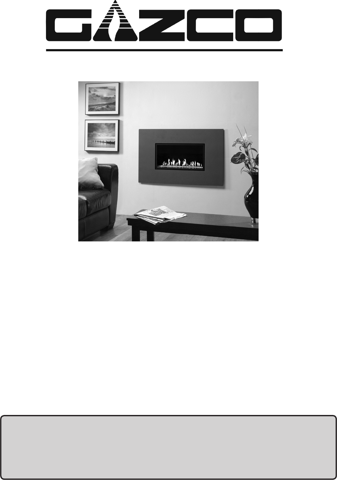
STUDIO
Conventional Flue
Instructions for Use,
Installation and Servicing
For use in GB, IE (Great Britain and Eire)
PR0957 Studio (Issue 3 - January 2008)
IMPORTANT
Do not attempt to burn rubbish in this appliance. This appliance must only be operated with the glass door secured firmly in
position. The front casing of this appliance will become hot whilst in operation, it is therefore recommended that a suitable
guard should be used for the protection of young children, the elderly or infirm.
These instructions must be left at the property for future reference and when servicing the fire.
The Commissioning Sheet found on page 3 must be completed by the Corgi Installer.
This appliance has been certified for use in countries other than those stated. To install this appliance in these countries, it is essential to obtain the
translated instructions and in some cases the appliance will require modification. Contact Gazco for further information.

2
COVERING THE FOLLOWING MODEL:
STUDIO 1 CONVENTIONAL FLUE:
8700CFCHEC 8701CFCHEC
P8700CFCHEC P8701CFCHEC
PAGE
APPLIANCE COMMISSIONING CHECKLIST 3
USER INSTRUCTIONS 4
INSTALLATION INSTRUCTIONS 8
Technical Specifications 8
Site Requirements 11
Installation 13
Commissioning 22
SERVICING INSTRUCTIONS 23
Fault Finding 23
How to replace parts 25
Basic spare parts list 31
Service Records 32
3
FLUE CHECK PASS FAIL
1. Flue is correct for appliance
2. Flue flow test
3. Spillage test
GAS CHECK
1. Gas soundness & let by test
2. Standing pressure test mb
3. Appliance working pressure (on High Setting) mb
NB All other gas appliances must be operating on full
4. Gas rate m3/h
5. Does ventilation meet appliance requirements
APPLIANCE COMMISSIONING CHECKLIST
Dealer .....................................................................
...............................................................................
...............................................................................
Contact No. ..............................................................
Date of Purchase .......................................................
Model No. ................................................................
Serial No. .................................................................
Gas Type .................................................................
Installation Company ................................................
. . . . . . . . . . . . . . . . . . . . . . . . . . . . . . . . . . . . . . . . . . . . . . . . . . . . . . . . . . . . . . . . . . . . . . . . . . . . . . . .
. . . . . . . . . . . . . . . . . . . . . . . . . . . . . . . . . . . . . . . . . . . . . . . . . . . . . . . . . . . . . . . . . . . . . . . . . . . . . . . .
Engineer ...................................................................
Contact No. ...............................................................
Corgi Reg No. ............................................................
Date of Installation ....................................................
IMPORTANT NOTICE
Explain the operation of the appliance to the end user, hand the completed instructions to them for safe keeping,
as the information will be required when making any guaranteed claims.
DEALER AND INSTALLER INFORMATION
This product is guaranteed for 2 years from the date of installation, as set out in the terms and conditions of sale between Gazco and your
local Gazco dealer. This guarantee will be invalid, to the extent permitted by law, if the above Appliance Commissioning Checklist is not
fully completed by the installer and available for inspection by a Gazco engineer. The guarantee will only be valid during the second year,
to the extent permitted by law, if the annual service recommended in the Instructions for Use has been completed by a Corgi registered
engineer, and a copy of the service visit report is available for inspection by a Gazco engineer.
4
USER INSTRUCTIONS
1. GENERAL
1.1 A competent person must carry out installation and
servicing.
1.2 In all correspondence, please quote the appliance type and
serial number, which can be found on the data badge
located on a plate inside the controls compartment
1.3 Do not place curtains above the fire:
You must have 300mm (1’) clearance between the fire and
any curtains at either side.
1.4 If any cracks appear in the glass panel do not use the
appliance until the panel has been replaced.
1.5 In the unlikely event the appliance is receiving interference
from other electronic devices, the handset/Control box can
be re-programmed. Please consult your dealer if you think
this may be the case.
1.6 This product is guaranteed for 2 years from the date of
installation, as set out in the terms and conditions of sale
between Gazco and your local Gazco dealer. Please consult
with your local Gazco dealer if you have any questions. In
all correspondence always quote the Model Number and
Serial Number.
2. LIGHTING THE STUDIO
There are two ways of lighting the Studio:
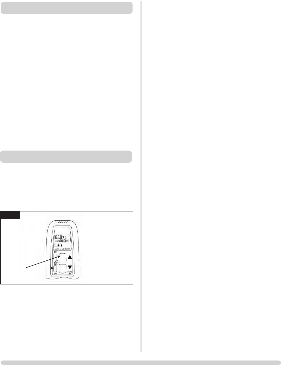
2A - THERMOSTATIC and TIMER REMOTE CONTROL
1
AR1883
Turning the Studio On
Your remote can control the gas fire from pilot ignition
through to shut down.
To turn the fire on:
The pilot and main burner ignite and the remote is now in
remote automatically maintains that temperature
set periods
NOTE: Wh E N O p E r a T i N g T h E f i r E iN TE m p O r Ti m E r m O d E ,
T h E p i l O T r E m a i N s l i T a N d T h E f i r E T h E N a u T O m a T i c a l l y
s W i T c h E s O N a T p r O g r a m m E d T i m E s T O b r i N g T h E r O O m T O
T h E s E T T E m p E r a T u r E W h E T h E r O r N O T y O u a r E iN T h E r O O m .
NEVER LEAVE ANY COMBUSTIBLE MATERIALS WITHIN 1
METRE OF THE FRONT OF THE APPLIANCE.
2.1 SWITCHING BETWEEN MODES
are:
DAY
and back to MAN
NOTE: MAN mode can also be reached by pressing
either the UP or DOWN arrow
2.2 MAN MODE
button to light the appliance. You hear a click as the fire
begins the ignition process , (up to 30 seconds)
stage
one stage
minimum
At the lowest point the fire goes to ‘standby mode’ (only
pilot lit)
NOTE: While pressing a button a symbol indicating
transmission appears on the display. The receiver
confirms transmission with an acoustic signal.
5
USER INSTRUCTIONS
Turning the Studio Off
2.3 TEMP MODE
The display shows the current room temperature.
To increase or decrease the fire’s output:
then let go
arrows. (Minimum temperature 5C, maximum 30C or
fahrenheit)
NOTE: If you set a temperature that is beneath the
current room temperature, the fire automatically
switches to OFF.
NOTE: If you would like the Night temperature control to
turn off then decrease the temperature until [---] is
displayed.
2.4 TIMER MODE
There are two programmable settings you can make over a
24 hour period, P1 and P2
P1 + = Start Timed Setting 1
P1 +
P2 + = Start Timed Setting 2
P2 +
2.4.1 P1 - Program 1 for a Timed Setting
time for P1. While the time displayed is flashing you can
alter the hours and minutes set.
To set the time your fire first lights, change the Start Timed
Setting for P1 .
in 10 minute increments
P1. The display shows the current setting for P1
This is the time your Studio first shuts down:
2.4.2 P2 - Program 2 for a Timed Setting
Use the same steps outlined in 2.4.1 to change the setting
for P2.
If you have already set P1 and want to alter the setting for
P2 only:
until the display flashes the
current time for P1
P1 and P1
still flashing:
wait to complete programming.
2.5 LOW BATTERY
“BATT” is displayed on the remote when its batteries need
replacement.
2.6 SETTING THE TIME
to set the minutes
2.7 SETTING THE °C/24 HOUR OR °F/12 HOUR CLOCK
from °C/24 hour clock to °F/12 hour clock and vice
versa.
If the remote is removed, lost or damaged, signals
transmitted to the receiver cease. Your fire will go to
standby (pilot) mode after 6 hours.
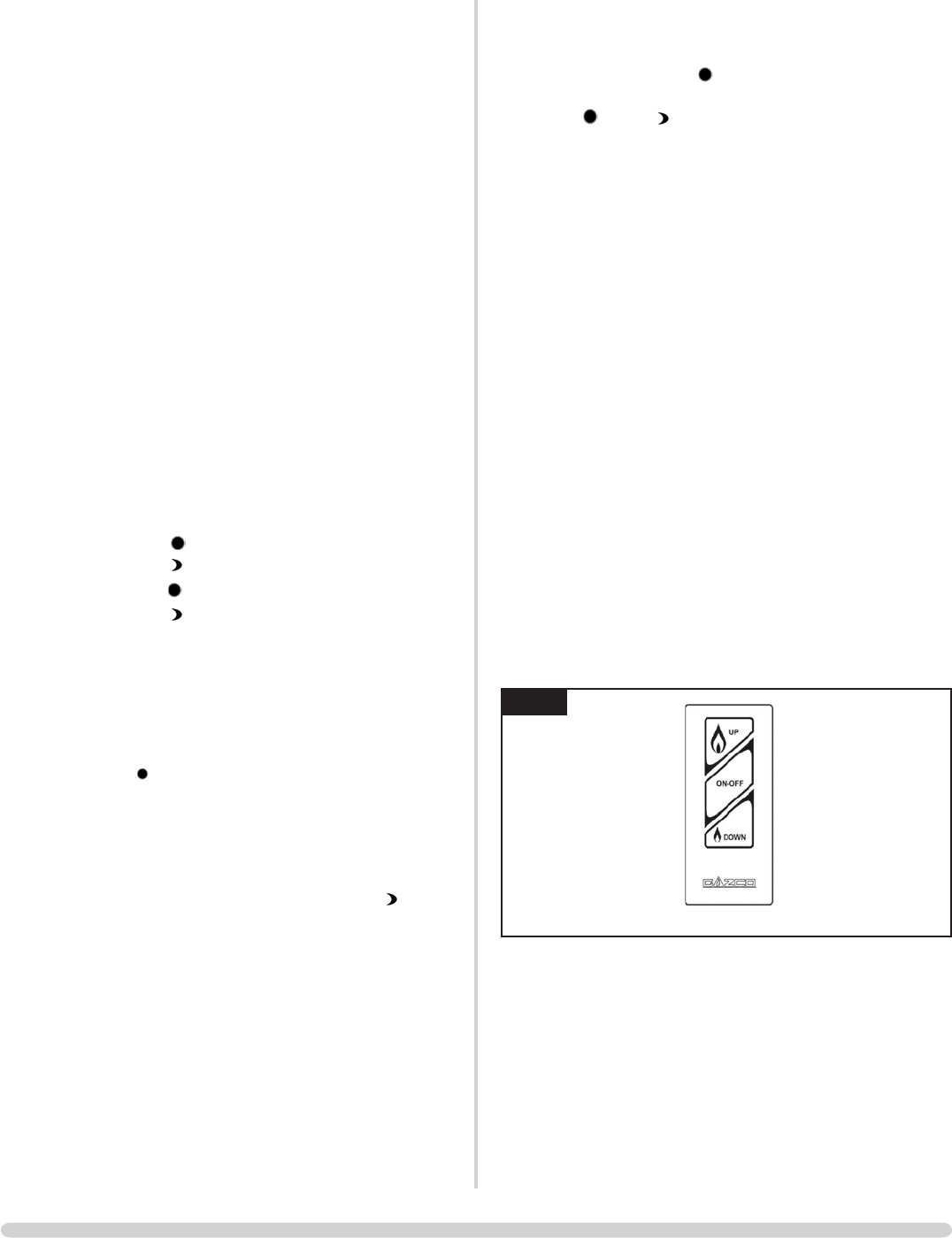
2B TOUCH PAD CONTROL
2
AR1885
30 seconds)
the lowest point it goes to ‘standby mode’, (only pilot
lit)
6
USER INSTRUCTIONS
EMERGENCY SHUT OFF
If the batteries fail during use of the fire, move the switch to
3
AR1961
3. CLEANING THE STUDIO
3.1 Make sure the fire and surrounds are cool before cleaning.
Use:
polished plate
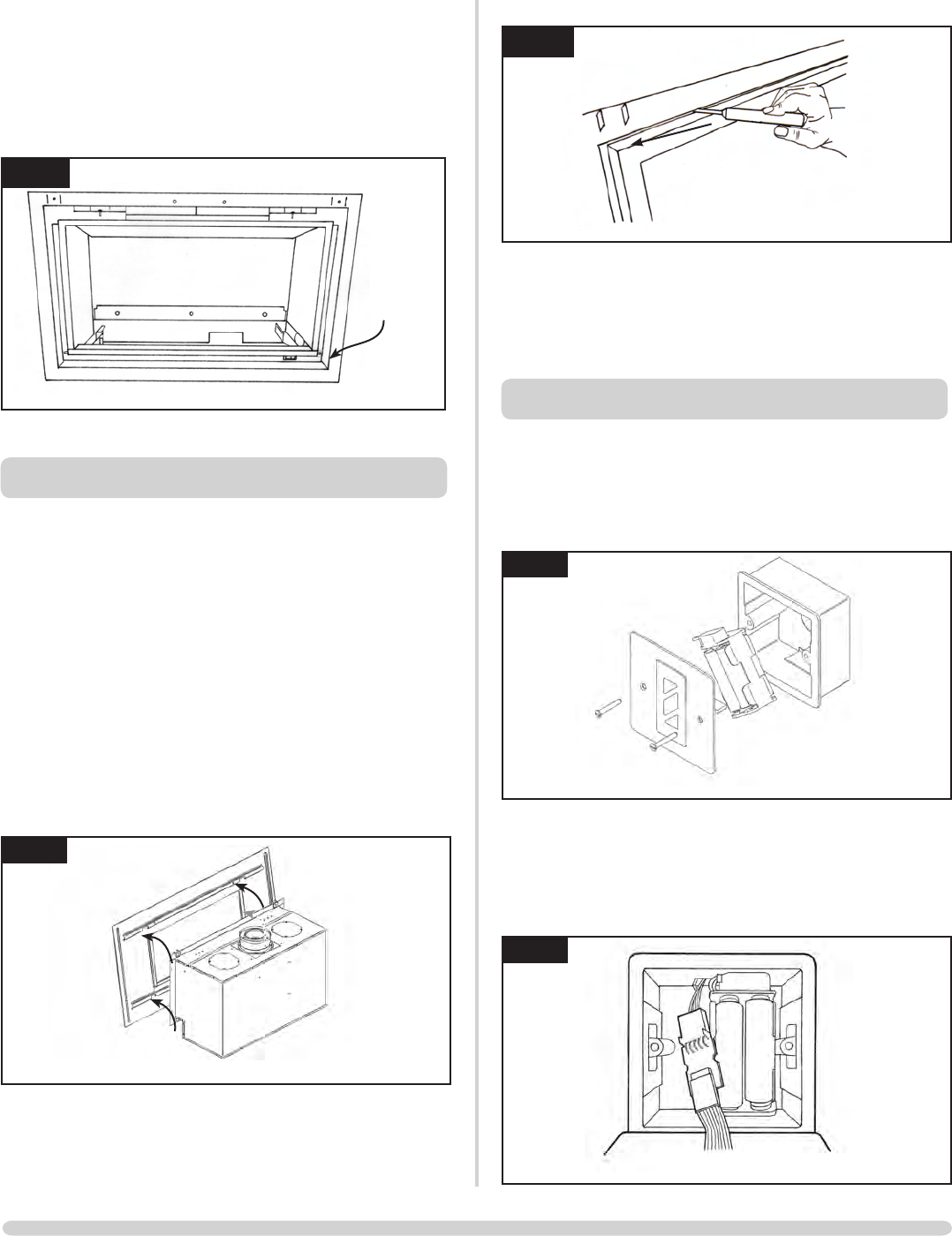
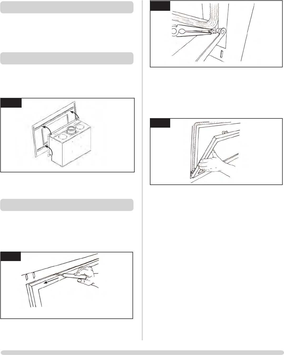
3.2 Opening the Glass Window
3.2.1 Steel Frame
[If fitted with a Steel Frame, this needs to be removed
first:
Diagram 4
4
3.3 All models
Using the allen key provided:
door, Diagram 5. The locks to move from shut to open
towards the outer edges of the glass door, Diagram 5
5
AR1860
When closing the window ensure the window catches are
fully engaged.
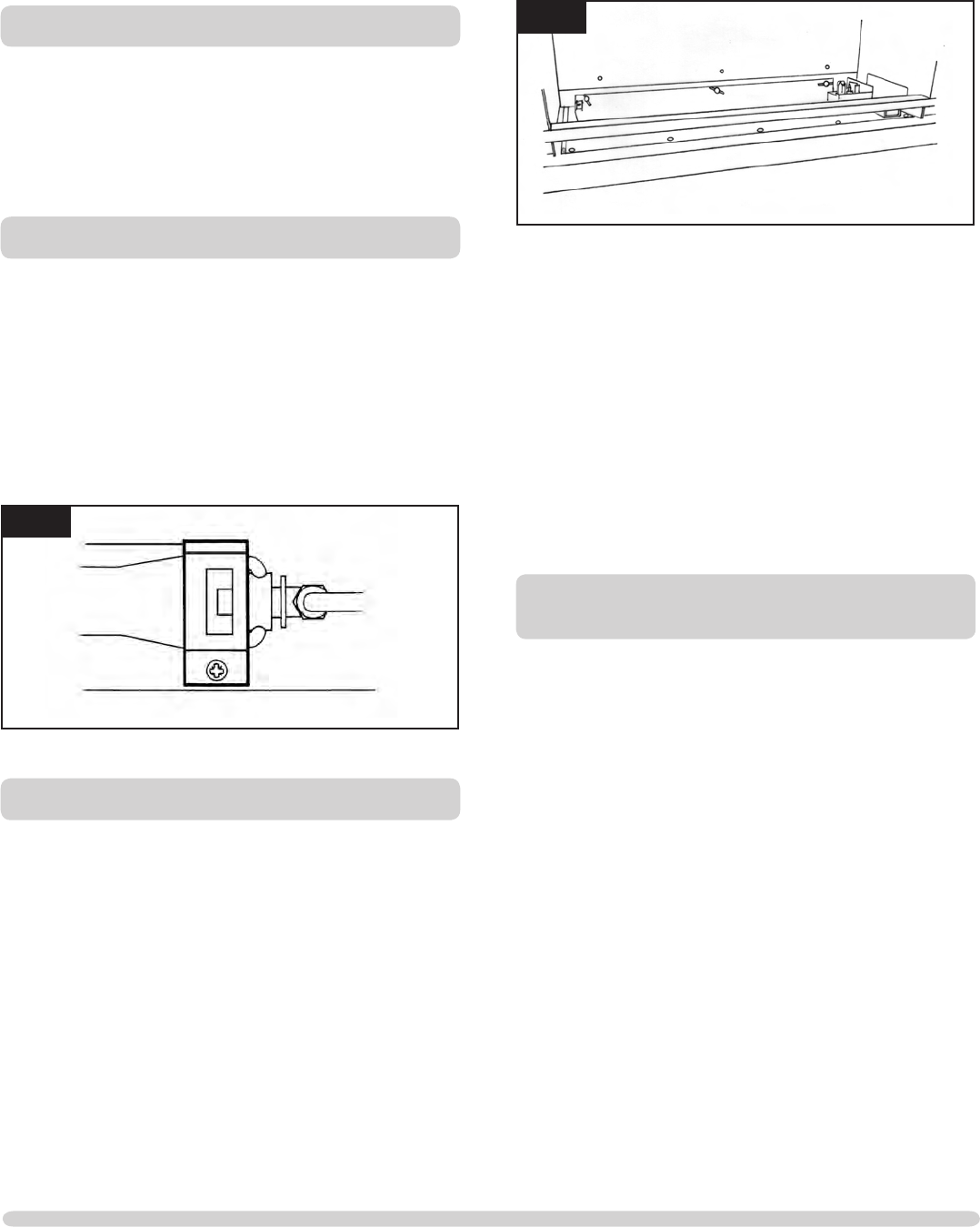
4. CHANGING THE STUDIO BATTERIES
The appliance batteries are located under the polished plate
mounting the wall switch.
and remove, Diagram 6
6
AR1887
the wall plate back onto the wall
7
AR1932

7
USER INSTRUCTIONS
5. ARRANGEMENT OF FUEL BED
5.1 If you need to replace pebbles or refill the tray, make sure
the pebbles are flattened so they are level with the rim of
the tray.
TAKE CARE NOT TO SPILL PEBBLES INTO THE PILOT
AREA
ONLY PEBBLES SUPPLIED BY GAZCO CAN BE USED IN
THIS FIRE.
6. FLAME FAILURE DEVICE
6.1 This is a safety feature incorporated on this appliance which
automatically switches off the gas supply if the pilot goes
out and fails to heat the thermocouple.
7. RUNNING IN
will "burn off" during the first few hours of use producing a
harmless and temporary odour. This will disappear after a
short period of use. If the odour persists, ask your installer
for advice.
8. SERVICING
8.1 The fire must be serviced every 12 months by a qualified
Model number and the Serial number which may be found
on the data badge.
9. VENTILATION
9.1 Any purpose provided ventilation should be checked
periodically to ensure that it is free from obstruction.
10. INSTALLATION DETAILS
10.1 Your installer should have completed the commissioning
sheet at the front of this book. This records the essential
installation details of the appliance. In all correspondence
always quote the Model number and Serial number.
11. HOT SURFACES
11.1 Parts of this appliance become hot during normal use.
and the infirm
12. FIRE WILL NOT LIGHT
12.1 If you cannot light the Studio:
(1) position, see Section 2, Emergency Shut Off
Consult your Gazco dealer if the Studio still does not light.
8
INSTALLATION INSTRUCTIONS
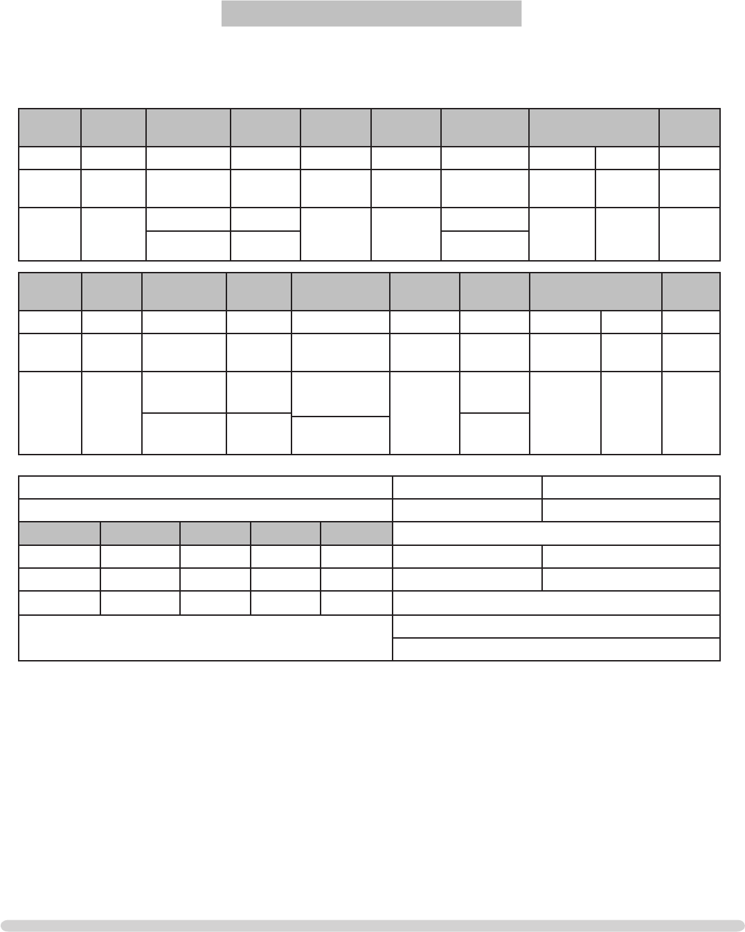
TECHNICAL SPECIFICATION
COVERING THE FOLLOWING MODELS:
STUDIO 1 CF: STUDIO 2 CF:
8700CFCHEC 8701CFCHEC
P8700CFCHEC P8701CFCHEC
Model Gas CAT. Gas Type Working
Pressure
Aeration Injector Gas Rate
m3/h
Input kW (Gross) Country
High Low
Studio 1
CF
12H Natural G20 20mbar 6 x 10 390 0.657 6.9 4.0 GB, IE
Studio 1
CF
13+
Propane G31 37mbar
Open both
sides
185
0.257
6.9 4.0 GB, IE
Butane G30 29mbar 0.197
Model Gas
CAT.
Gas Type Working
Pressure
Aeration Injector Gas Rate
m3/h
Input kW (Gross) Country
High Low
Studio 2
CF
12H Natural G20 20mbar 9 x 15
offset
530 0.791 8.3 4.2 GB, IE
Studio 2
CF
13+
Propane G31 37mbar One side open
+ 10 x 16 225
0.312
8.3 4.2 GB, IE
Butane G30 29mbar 0.238
Open both
sides
Studio 1 Efciency Class 2 - 70% NOx Class 4
Studio 2 Efciency Class 2 - 78% NOx Class 4
Weight Fire Only Prol Bauhaus Steel Flue Size
TOP EXIT REAR EXIT
Studio 1 52 Kg 3.6 Kg 3.6Kg 18.5Kg 127mm ø178mm ø minimum
Studio 2 60Kg 4.6Kg 4.6Kg 21.8Kg Gas Inlet Connection Size = 8mm ø
Minimum Flue Specication = T260/N2/0/D/1
Minimum Flue Temp = 220oC
9
INSTALLATION INSTRUCTIONS
TECHNICAL SPECIFICATION
This appliance has been certified for use in countries other than
those stated. To install this appliance in these countries, it is
essential to obtain the translated instructions and in some cases
the appliance will require modification. Contact Gazco for further
information.
PACKING CHECKLIST
Qty Description Fixing Kit containing:-
1 x Instruction Manual
4 x Rawl Plugs
1 x Handset
4 x AA cell batteries
1 x 9V cell batteries
1 x wall box
1 x touch pad/wall plate
1 x battery holder
AR1952
10
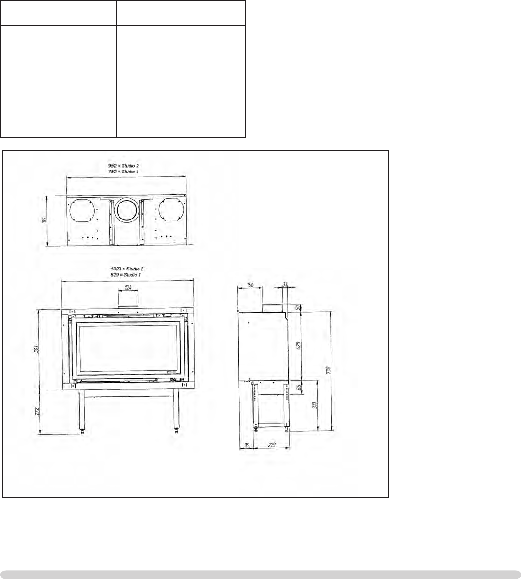
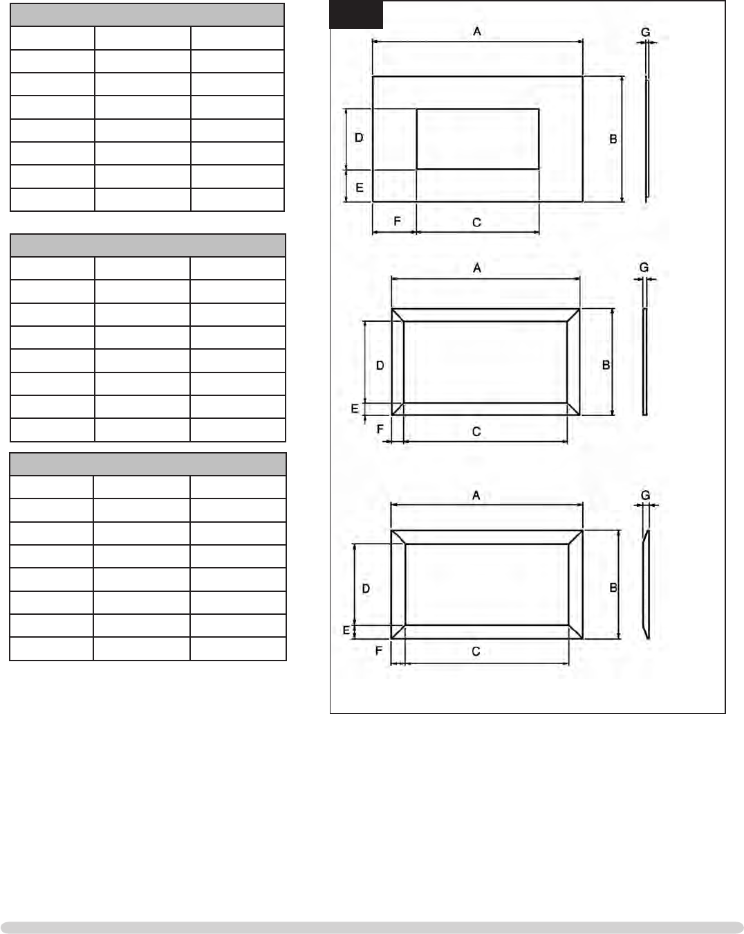
INSTALLATION INSTRUCTIONS
TECHNICAL SPECIFICATION
2Steel
Profil
Bauhaus
STEEL FRAME DIMENSIONS
Dimension Studio 1 Studio 2
A 1120 1350
B 675 675
C 646 846
D320 320
E 177 177
F 237 237
G 25 25
PROFIL FRAME DIMENSIONS
Dimension Studio 1 Studio 2
A 846 1046
B 520 520
C 750 950
D424 424
E 48 48
F 48 48
G 12.5 12.5
BAUHAUS FRAME DIMENSIONS
Dimension Studio 1 Studio 2
A 860 1060
B 534 534
C 750 950
D424 424
E 55 55
F 55 55
G 28 28
11
INSTALLATION INSTRUCTIONS
SITE REQUIREMENTS
1. FLUE AND CHIMNEY REQUIREMENTS
WHEN INSTALLING A FLUE SYSTEM PLEASE REFER TO
THE MANUFACTURER’S INSTRUCTIONS.
and flues by their temperature, pressure and resistance to
corrosion, condensation and fire. To identify the correct flue
system, the minimum flue specification is shown in the
Technical Specification
by this system.
The flue must be installed in accordance with all local and
national regulations and the current rules in force:
spigot to the roof terminal
metres (10ft)
fully open position and no restrictor plates fitted
installing the appliance, but it need not be swept if you can
see the chimney is clean and free from obstruction
throughout
2. FLUE OPTIONS
There are three suitable Conventional Flues:
• Stud work is Top Exit only - Twin Wall Rigid
127mm (5”)
• Top Exit - Builder’s Opening Lined
127mm (5”)
• Rear Exit - Builder’s Opening Unlined
178m (7”) minimum
3. GAS SUPPLY
THIS APPLIANCE IS INTENDED FOR USE ON A GAS
INSTALLATION WITH A GOVERNED METER.
3.1 Make sure local distribution conditions (identification of the
appliance are compatible before installation.
and is in accordance with the rules in force.
3.3 You can use soft copper tubing on the installation and soft
3.4 A factory fitted isolation device is part of the inlet
connection; no further isolation device is required.
3.5 All supply gas pipes must be purged of any debris that may
have entered prior to connection to the appliance.
3.6 The gas supply enters through the silicone panel located on
through
3.7 The gas supply must be installed in a way that does not
restrict the removal of the appliance for servicing and
inspection.
4. VENTILATION
IMPORTANT: Ensure any national ventilation
requirements are taken into account during installation
of the fire.
UK ONLY:
does not normally require any additional permanent
ventilation.
The Studio 2 must have permanent ventilation with a
minimum open area of 5.85cm2.
FOR THE REPUBLIC OF IRELAND REFER TO THE RULES
IN FORCE FOR VENTILATION REQUIREMENTS
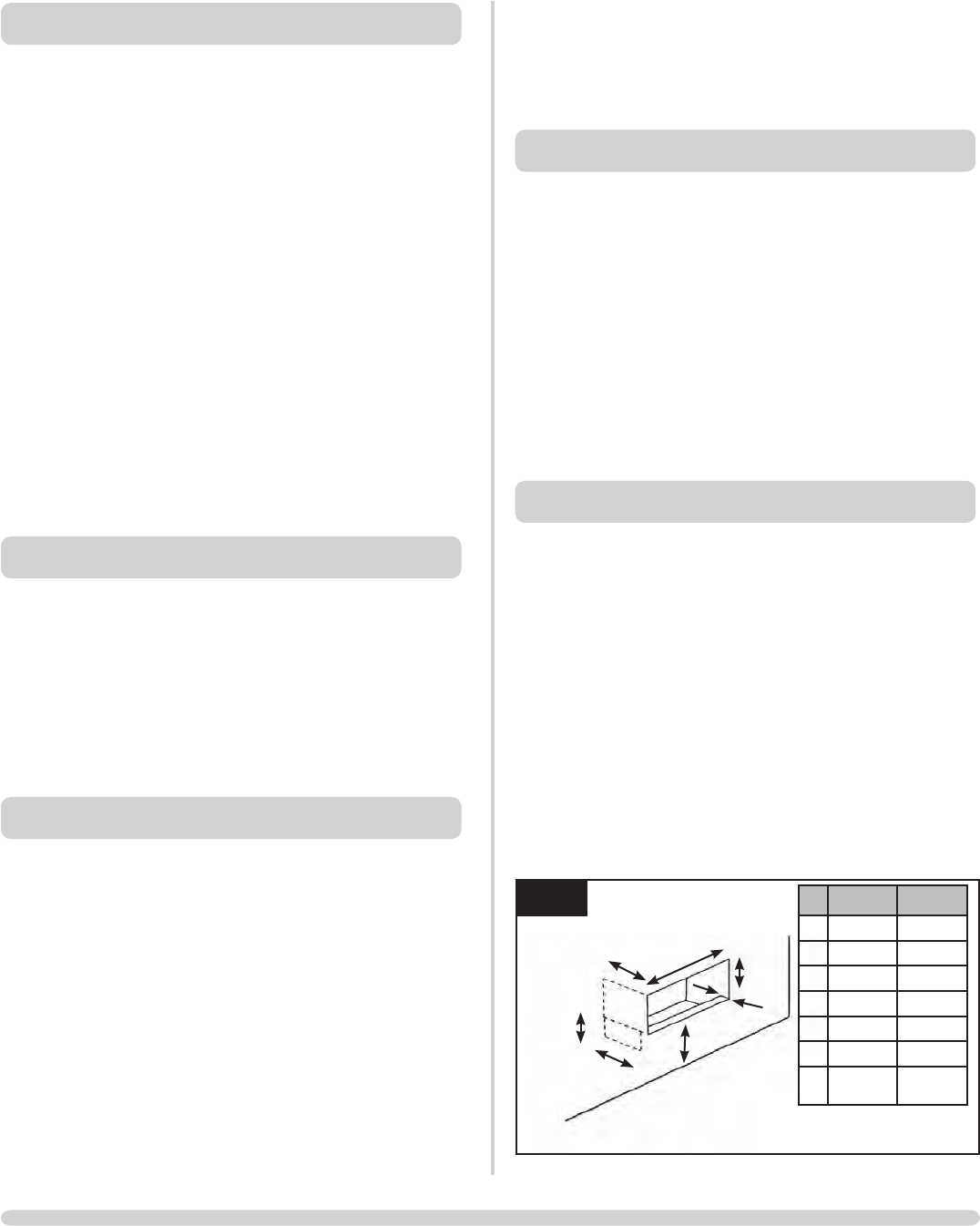
5. APPLIANCE LOCATION
NOTE: It is recommended you construct the back panel
of the fireplace from natural materials cut into three or
more sections to prevent cracking. Resin-based materials
may not be suitable. This appliance is an effective heat
producer and attention must be paid to the construction
and finish of the fireplace.
opening, the front of the wall must be cut out down to the
level on which the appliance is to stand. Then, to obtain the
correct dimensions shown in Diagram 1a, the lower section
of wall must be reconstructed as shown in Diagram 1a
5.1 This appliance must stand on a non-combustible base that is
at least 12mm thick; the minimum opening dimensions are
shown in Diagram 1a.
AR1906
1a
C
D
A
E
G
F
B
Studio 1 Studio 2
A 760mm 960mm
B 440mm 440mm
C 350mm 350mm
D85mm 85mm
E 305mm 305mm
F 45mm max 45mm max
G 175mm
min
175mm
min
12
INSTALLATION INSTRUCTIONS
SITE REQUIREMENTS
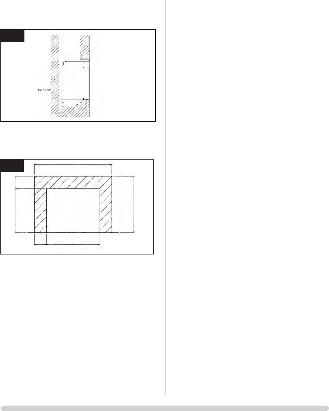
without a liner, there must be a minimum debris collection
area, Diagram 1b
AR2006
1b
5.3 DO NOT install onto a combustible wall; all combustible
materials must be removed from the area shown in Diagram
1c.
1c
AR1226
1160
not to
scale
400
440
960
840
100
5.4 A combustible shelf must be a minimum of 400mm above
the top of the appliance. This is based on a 150mm deep
shelf. For every extra 13mm of depth add 25mm above the
400mm from the top of the appliance, not the frame.
5.5 A side wall must be a minimum of 300mm from the side of
the appliance, not the frame.
13
IMPORTANT:
SERVICING
1. SAFETY PRECAUTIONS
1.1 For your own and other’s safety, you must install this
appliance according to local and national codes of practice.
Failure to install the stove correctly could lead to
prosecution:
stove.
1.2 These instructions must be left intact with the user.
1.3 Do not attempt to burn rubbish on this appliance.
allow adequate clearance above the appliance.
IF THE APPLIANCE IS EXTINGUISHED OR GOES OUT IN
USE, WAIT 3 MINUTES BEFORE ATTEMPTING TO
RELIGHT THE APPLIANCE.
2. INSTALLATION OF THE APPLIANCE
1.1 This appliance can be installed in four different ways:
1) Builder’s opening with a frame
2) Builder’s opening without a frame
3) Stud work with a frame
4) Stud work without a frame
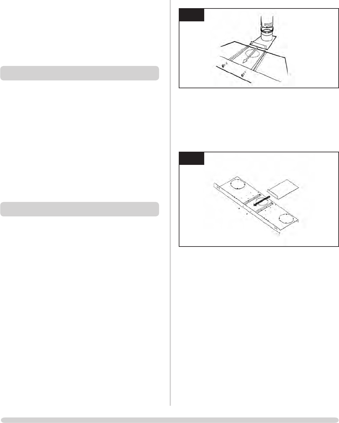
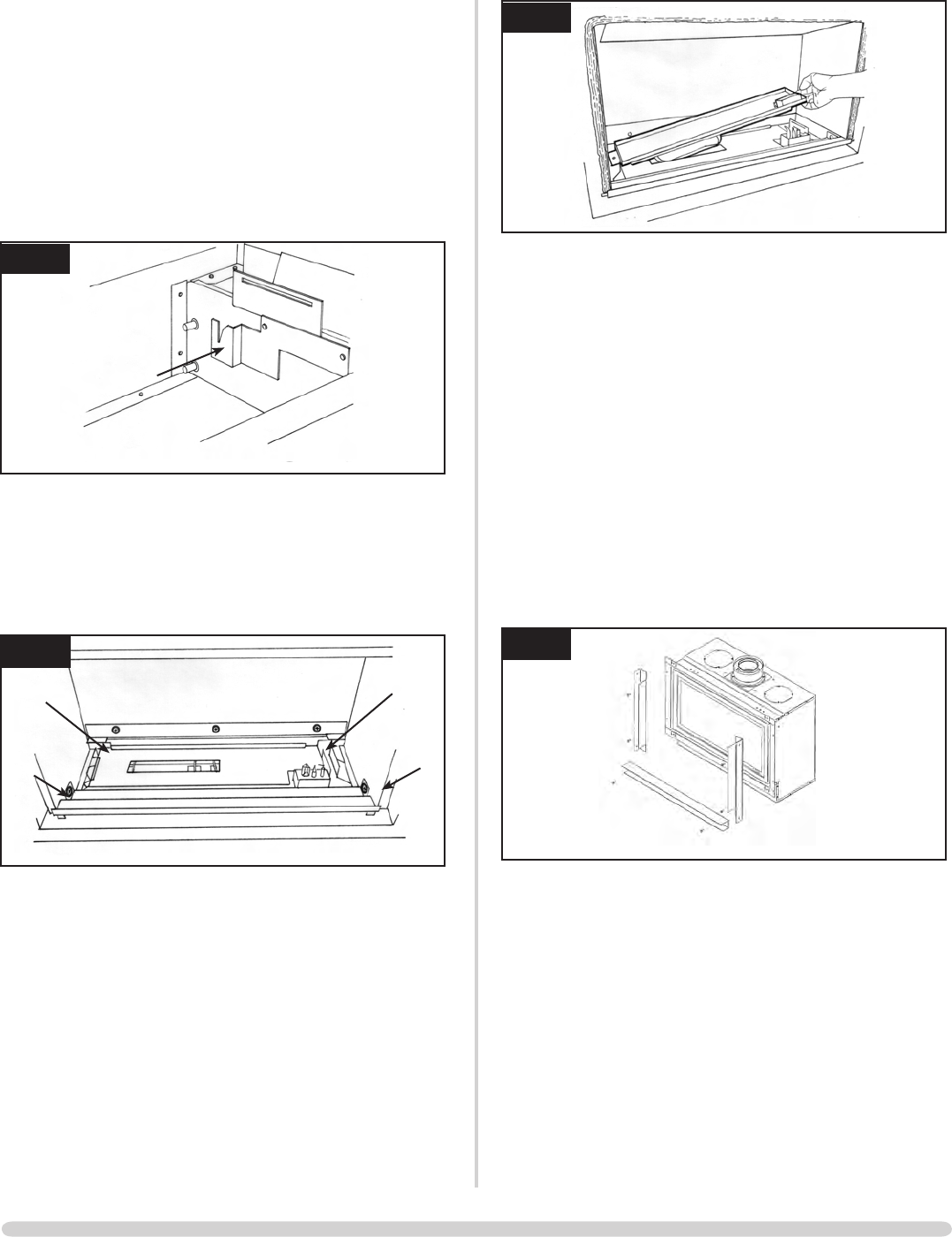
1.2 The Studio is supplied with a flue fixing plate to attach the
flue to the appliance within the aperture, Diagram 1.
AR1010
1
without a liner, it must be converted to a rear exit:
assembly
AR2007
2
The flue must be in good condition and clear products of
combustion, see Commissioning)
rigid twin wall flue pipe.
THE APPLIANCE IS SUPPLIED WITH A WALL BOX
CONTAINING THE BATTERIES AND TOUCH PAD. THIS
MUST BE RECESSED INTO THE WALL WITH ACCESS
FOR THE CABLES PRIOR TO FITTING THE APPLIANCE.
2.1 Remove the appliance from the carton and discard all
away when unpacking.
2.2 To access the controls and gas inlet:
splitter plate. See Section 4
2.3 The gas supply enters the fire through a silicon panel on the
floor under the access panel, Diagram 3:
pipe, Diagram 1
INSTALLATION INSTRUCTIONS
INSTALLATION
14
INSTALLATION INSTRUCTIONS
INSTALLATION
3
AR1963
3. STUD WORK INSTALLATION
THERE IS AN OPTIONAL DUCT KIT, CODE No. 8572
WHICH CAN BE FITTED AT THE SAME TIME AS THE
APPLIANCE INSTALLATION.
3.1 Combustible parts of the stud work must be kept beyond
framework is protected by non-combustible material, you
must maintain these dimensions, Diagram 4.
4
AR1953
3.1.1 Do not pack the void around or above the appliance with
insulation materials such as mineral wool.
3.1.2 Th E v O i d b u i l T f O r T h E c a s s E T T E m u s T b E v E N T i l a T E d T O
p r E v E N T a b u i l d -u p O f h E a T . if T h E v O i d is s E a l E d , T h E N y O u
m u s T f i T v E N T s a T b O T h l O W a N d h i g h l E v E l s O f a p p r O x i m a T E l y
50c m 2 E a c h . Th E s E v E N T s m u s T T a k E c O l d a i r f r O m T h E r O O m
a N d r E T u r N W a r m a i r b a c k i N T O T h E r O O m .
3.1.3 aN a c c E s s h a T c h m u s T b E l E f T i N T h E s i d E O f T h E c h i m N E y
b r E a s T f O r f u T u r E s E r v i c i N g a N d i N s p E c T i O N O f T h E f l u E a N d
a p p l i a N c E .
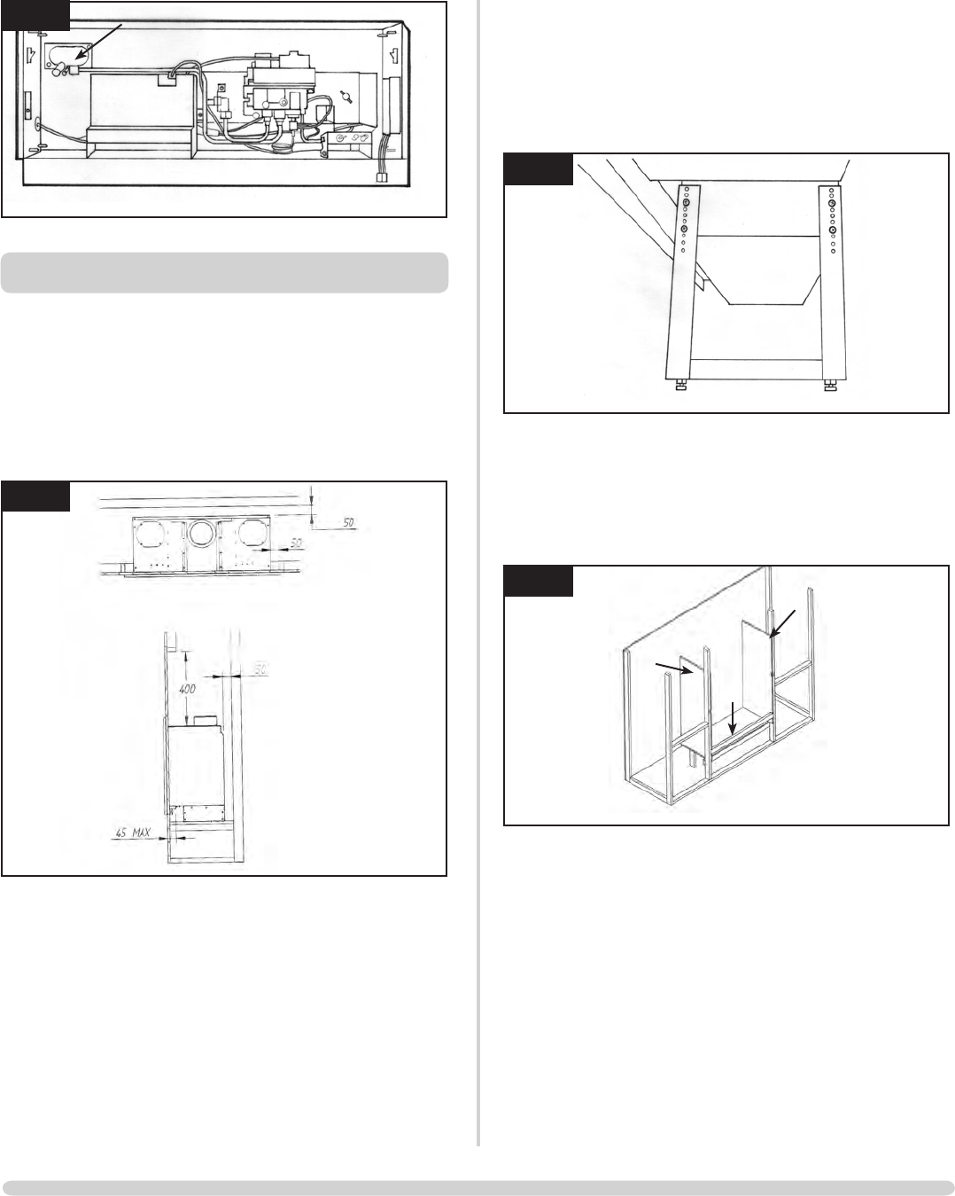
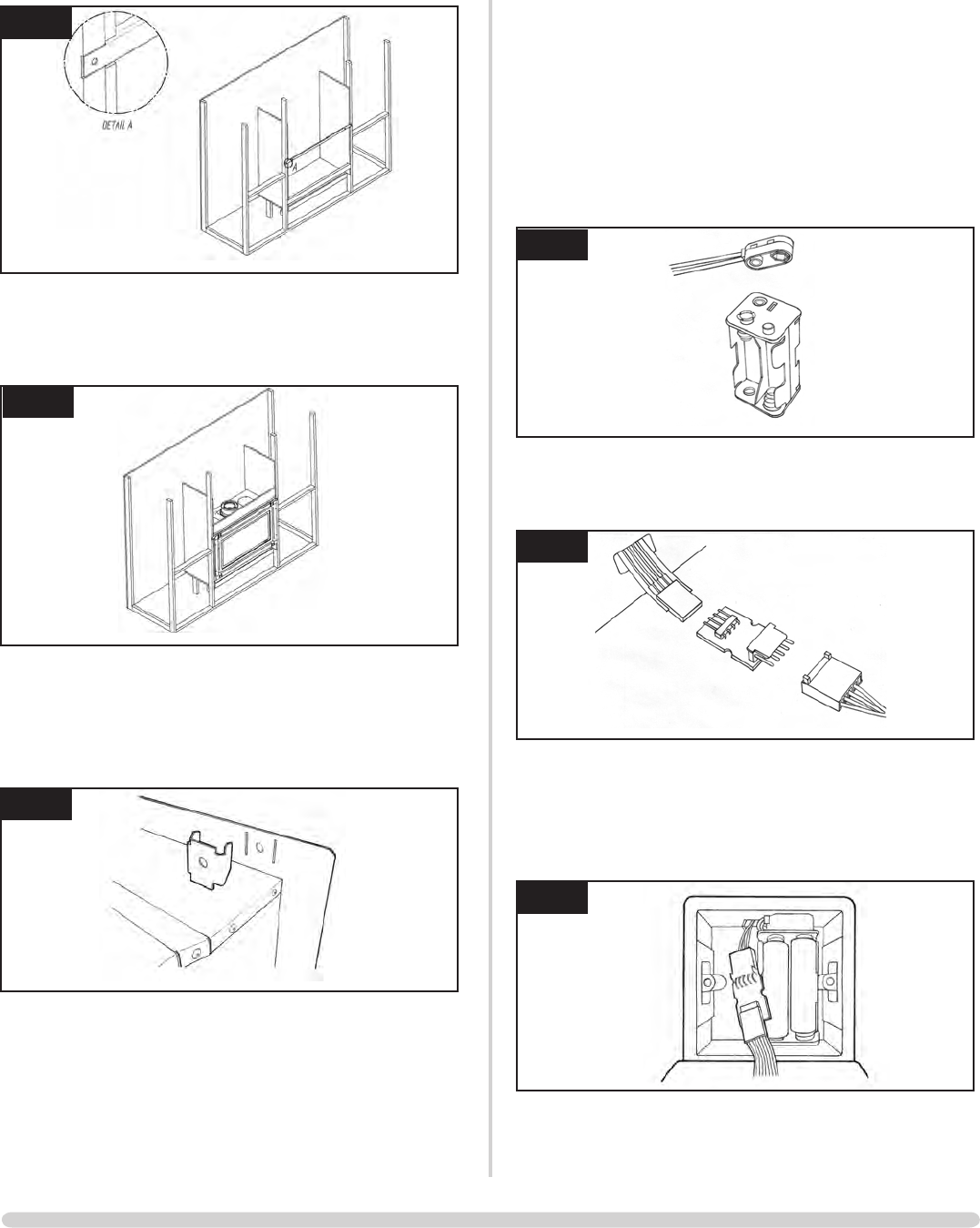
3.2 STUD WORK INSTALLATION METHOD 1 (FRAME)
NOTE: With the legs fitted, this appliance can stand
directly on the floor (normally in a false chimney breast),
or without the legs on a protected platform at the
required height, Diagram 5
5
AR1964
Build the stud work chimney breast and enclosures to the
desired size to include the protected platform at the
required height.
non-combustible material as shown, Diagram 6
6
AR1902
void on the left-hand side
into the stud work at the correct height. This bar needs to
be recessed into the stud work, Diagram 5
It may be advisable at this stage to remove the fire before
plastering the enclosure.
15
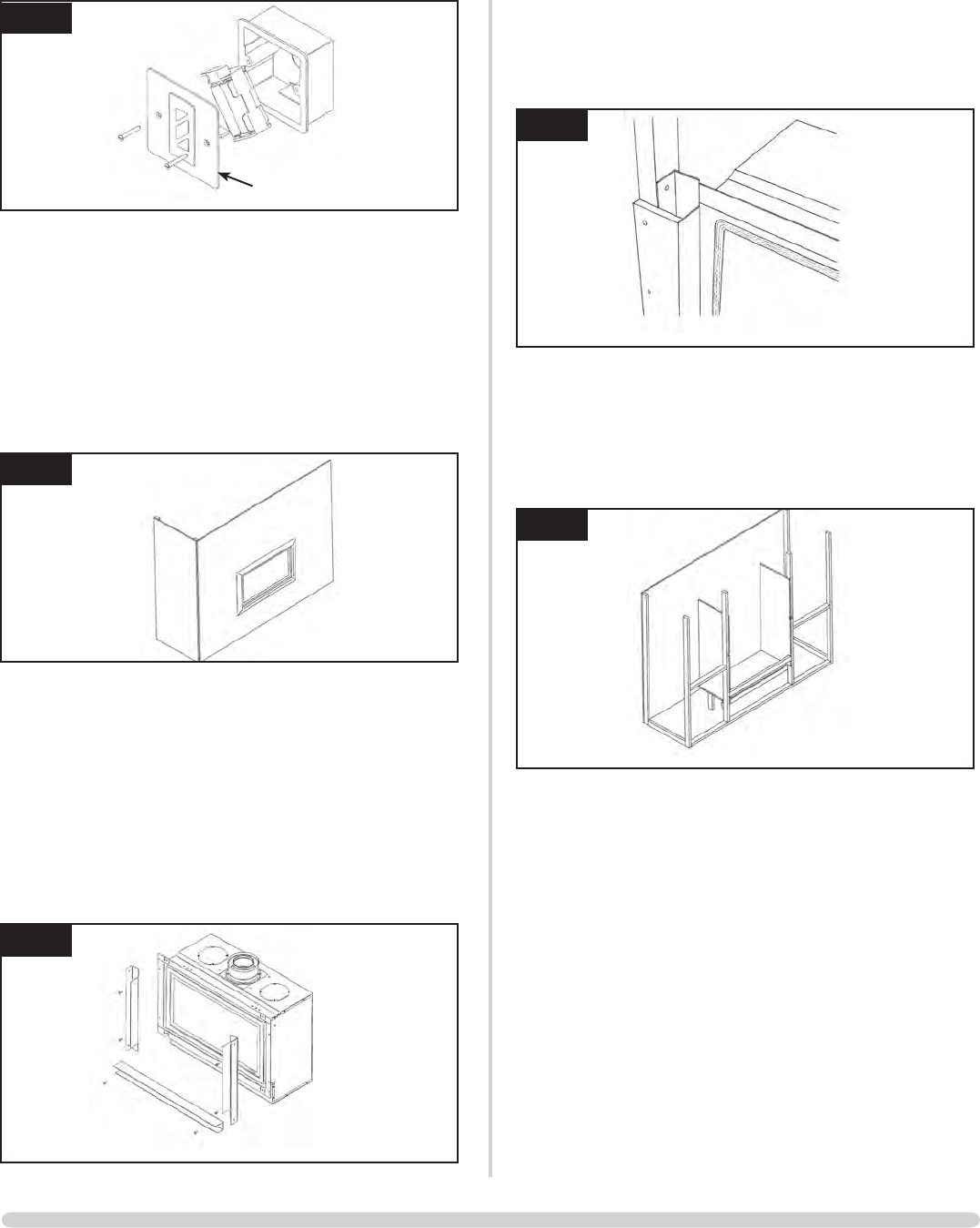
INSTALLATION INSTRUCTIONS
INSTALLATION
7
AR1903
correct height, Diagram 8, because no combustible material
can be used above the fire
8
AR1904
installing the appliance.
9
AR1913
fire This should extend a minimum of 400mm above the
appliance and at least 50mm to the sides of the appliance
(from the outer box, not the flanges).
For non-combustible area see Diagram 2b.
The remaining area can be finished using plasterboard:
through flange, bracket, support bar
batteries and wall switch
Diagram 10
10
AR1920
connector, Diagram 11
11
AR1919
the wall plate back onto the wall
12
AR1905
wall box, Diagram 13
16
INSTALLATION INSTRUCTIONS
INSTALLATION
13
AR1887
wall plate
Because of the high temperatures this fire achieves, it is
advisable to use marble slips or similar material between the
appliance and the plasterboard
Never use a one-piece slip as expansion (even cracking)
can occur. If a slip is used, longer screws are needed to
secure the appliance.
opening in the side of the chimney breast for access. After
commissioning, finish the sides of the chimney breast,
Diagram 14
14
AR1905
3.3 STUD WORK INSTALLATION METHOD 2 (EDGE)
the fire is channelled into the chimney cavity and vented at
the top.
of the fire, Diagram 15. There is a deliberate gap at the top
for convected heat
15
AR1912
This now determines the width of your two vertical stud
work supports. The kit has been designed so that 12mm
thick plasterboard can be taken to the three channels,
Diagram 16
16
AR1934
the channel
Build the stud work chimney breast to the desired size:
maintained, 3.1 above
17
AR1902
fire. This should extend a minimum of 400mm above the
appliance.
batteries and wall switch
up the wires from the fire, see Stud Work Installation with
Frame for wiring detail on previous page
opening in the side of the chimney breast for access
After commissioning, finish the sides of the chimney breast,
Diagram 18
17
INSTALLATION INSTRUCTIONS
INSTALLATION
20
AR1862
This releases the left-hand side off its hinge pin
move the door to the right to release it from the right pin
The door is now free to remove, Diagram 21
21
AR1863
panel whilst removing the second side to prevent it falling).
22
AR1865
18
AR1911
The top of the chimney breast must have a minimum
200mm2 vent.
NOTE: Refer to paragraph 4.11 to check gas pressure
4. MASONRY CHIMNEY INSTALLATION
NOTE: Do not use the legs (of the appliance) in this installation
Using the allen key provided:
The locks need to be moved from shut to open towards the
outer edge of the door, Diagram 19.
19
AR1860
Diagram 20
18
INSTALLATION INSTRUCTIONS
INSTALLATION
23
AR1965
burner
The front of the plate can now be lifted off the screws:
24
AR1966
25
AR1966
loose box, Diagram 26.
26
AR1967
the appliance
4.8 METHOD 1 - FRAME
flanges.
Diagram 27
27
AR1913
the screws and rawl plugs provided through the top and
bottom flanges, Diagram 28
28
AR1913
19
INSTALLATION INSTRUCTIONS
INSTALLATION
grommet in the left side of the loose box
The wires are then fed inside the firebox and routed
through the available access
the wires are not trapped
in the tapered brackets, Diagram 29
29
AR1968
NOTE: To check gas pressure refer to paragraph 4.11
Diagram 30
30
To replace the burner:
venturi and also the pilot into the aperture in the burner
skin
the slot in the bracket
31
AR1965
To replace the doors and panels, refer to Replacing Parts,
Section 3 and 5
4.9 METHOD 2 - NO FRAME
The front of the chimney breast has to be studded and
boarded to allow the edge kit to be fitted.
the fire is channelled into the cavity between the existing
chimney and the false wall, then vented at the top. The
vent should have a minimum open area of 200mm.
Section 4.1 to 4.8, but do not fit
the frame brackets
You have now removed the box from the appliance and
should use the following:
screws and rawl plugs provided, Diagram 32
32
AR1912
described in Section 3.3, Diagrams 14, 15.
Fit the non-combustible board and the plasterboard as
described in Section 3.3
20
34
AR1865
5.3 To fit the window frame:
uppermost
35
AR1863
the left hinge pin
Diagram 36
INSTALLATION INSTRUCTIONS
INSTALLATION
BOTH METHOD 1 OR 2 - MASONRY INSTALLATION
connect it to the gas supply pipe
As the loose box is fitted into the main appliance:
panel on the left side
rear of the appliance and lower the front edge
PURGE THE SUPPLY PIPE. This is essential to expel any
debris that may block the gas controls
33
33
AR1963
located on the inlet fitting
The burner must be temporarily fitted whilst completing this
procedure
supply pressure is as stated on the data badge
5. ASSEMBLING THE APPLIANCE
are level with the rim of the tray
21
INSTALLATION INSTRUCTIONS
INSTALLATION
36
AR1862
5.5 Using the allen key provided:
towards the window centre
37
AR1860
6. LIGHTING THE STUDIO
Note: The Emergency Shut Off switch must be in the ON
position, refer to Section 2, User Instructions.
There are two ways of lighting the Studio:
THERMOSTATIC REMOTE CONTROL
38
AR1883
Turning the Studio On
Your remote can control the gas fire from pilot ignition
through to shut down.
To turn the fire on:
The pilot and main burner ignite and the remote is now in
TOUCH PAD CONTROL
39
AR1885
30 seconds)
the lowest point it goes to ‘standby mode’, (only pilot
lit)
22
7. COMMISSIONING
7.1 Check the flame picture
7.2 Check the gas pressure
diverter opening and check all smoke is drawn in along the
opening
If there is any doubt:
the test, Diagram 40
40
AR0757
rooms, the test must be repeated with the fans running on
maximum.
IF SPILLAGE PERSISTS, DISCONNECT THE APPLIANCE
AND SEEK EXPERT ADVICE.
For future reference, record the installation details on the
Commissioning Sheet on page 3.
COMMISSIONING
23
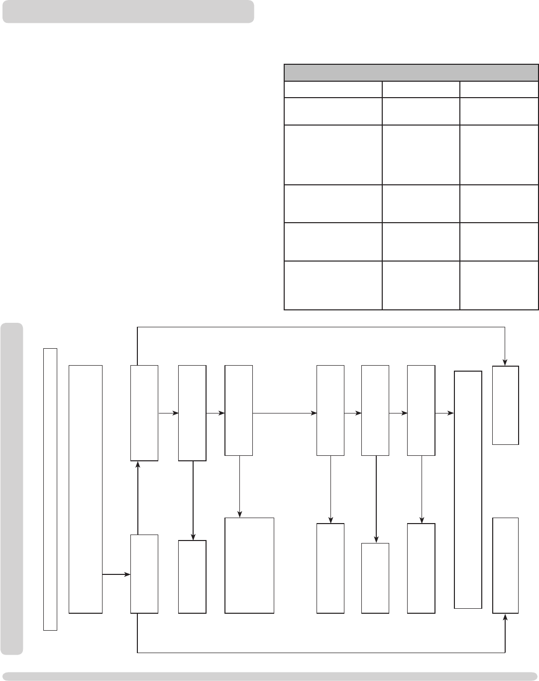
IGNITION FUNCTIONAL CHECK 1
(e.g. soot, etc.) which could short the spark, clean the area.
Is there a spark?
Consult User
Instructions and retry.
Check alignment of pilot
burner head, change the
ignition lead.
See Replacing Parts, section 2.
Check isolation tap and
gas meter, retry.
Correct and
retry.
Purge the gas pipes and retry.
GO TO THE NEXT
CHART IGNITION
FUNCTIONAL CHECK 2
SYSTEM OK
There is a blockage in the system, check the inlet test point,
the mag seating and valve. Check thermocouple leads for correct orientation,
condition and connection
Is the gas turned on to the
appliance?
Is the gas pressure correct?
Has the system got
any air in it?
Does the pilot light?
Is the control being
operated correctly?
with a match?
No Yes
No
Yes
No
Yes
Yes
No
No
Yes
No
No
Yes
Yes
SERVICING INSTRUCTIONS
SERVICING / FAULT FINDING CHARTS
1. SERVICING REQUIREMENTS
This appliance must be serviced at least once a year by a
competent person.
All tests must be serviced by best practice as described by the
1.1 Before any tests are undertaken on the stove:
there are no gas leaks prior to starting work.
Special checks
1.2.1 Clean any lint or fluff from the pilot - pay particular
attention to the aeration hole in the side of the pilot
1.2.2 Clean away any fluff or lint from under the burner
1.2.3 Check the spark gap on the pilot is correct
checks
1.3 Advise the customer of any remedial action taken.
REPLACE BATTERIES BEFORE ATTEMPTING TO RECTIFY ANY
FAULTS
IF THE FIRE DOES NOT WORK, BUT HAS WORKED IN THE
PAST:
• CHECK THE EMERGENCY SHUT OFF SWITCH,
(BOTTOM RIGHT CORNER BY THE DOOR), IS
SWITCHED ON, SEE USER SECTION, PAGE 6
ELECTRONIC CONTROL VALVE FAULT ANALYSIS
Symptom Cause Remedy
3 short beeps from
control
Batteries low in
appliance
Replace appliance
batteries
No ignition, 5 seconds
continuous tone (there
can be several short
beeps before)
1. ON/OFF
switch is in OFF
position
2. Loose/dam-
aged wire
1. Move switch to
ON position
2 Check
interrupter block
and wires
No ignition, no tone,
motor turned slighted
when operated
Receiver board
damaged
Replace receiver
No pilot ame and
control continues to
spark
Thermocouple
circuit wired
incorrectly
Correct wiring
Pilot lights, control
continues to spark,
vale shuts down after
10-30 seconds
1. No spark at
pilot burner
2. Loose/dam-
aged wire
1. Rectify spark at
pilot burner
2. Check inter-
rupter and wires
24
SERVICING INSTRUCTIONS
FAULT FINDING CHARTS
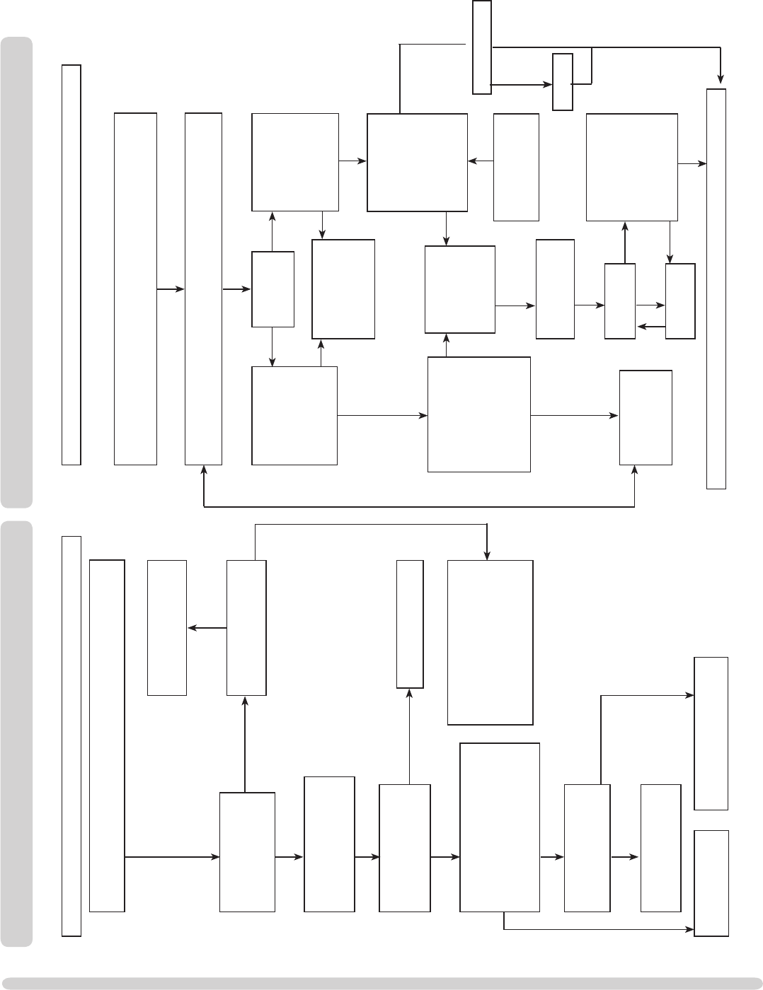
(e.g. soot etc.) Check for fluff in the pilot aeration hole.
See the Diagram in the Replacing Parts section.
Problem is with the
pipe work or
fittings which lead
to the fire. Correct
and retry.
Is thermocouple
connection good
in back of valve?
Replace pilot unit.
stay alight?
Change mag
unit.
Is the pilot flame of the
correct length? Are the
thermocouple leads
damaged or loose in the
interrupter block? Is the
(I) position. See diagram ?
Change the pilot unit
or damaged
thermocouple leads
stay alight?
running is the gas
pressure as stated on
the data badge?
on full is the gas at
the pressure stated
on the data badge?
Run for 3 mins,
turn off, time interval
until mag unit shuts
with a click. Is this
greater than 7
seconds?
Run for 3 mins, turn
off, time interval until
mag unit shuts with a
click. Is this greater
than 7 seconds?
Tighten the
connection and retry.
No
No
No
No
No
No
Yes
SYSTEM OK
Yes
Yes
Yes
Yes
No
Yes
No
Light the pilot using either the handset or the touch pad
FLAME FAILURE FUNCTIONAL CHECK 3IGNITION FUNCTIONAL CHECK 2
(e.g. soot etc.) which could short the spark, clean the area.
Consult the users
instructions, retry.
From Ignition Fault
Finding Chart 1
Is the gap between
electrode and
thermocouple 4.0mm?
Has ignition lead
become detached or is
connection poor?
Remove the ignition lead
pliers. Hold the tip 4.0mm from the
pilot pipe work, is there a spark
when the system is operated?
Has the ignition lead
become detached from the
control box?
Replace the lead, retry.
Correct and retry.
Replace if required. Check handset is
I). Check batteries to the
control unit. Replace if required.
Retry with handset and touch pad.
Is the valve being
operated correctly? Yes
Yes
Yes
No
No
No
Yes
Yes
Yes
No
Replace the electrode Replace the ignition
lead and retry.
No
Is the flue working?
Rectify flue
Yes
No
25
AR1862
3
hinge pin
Still keeping the frame upright:
4
AR1863
the right hinge pin. The window frame is now free.
1. GENERAL
1.1 All main components can be replaced without removing the
stove from its installation. iT i s E s s E N T i a l T h a T T h E g a s s u p p l y
T O T h E s T O v E is T u r N E d O f f a T T h E i s O l a T i O N d E v i c E b E f O r E
p r O c E E d i N g f u r T h E r .
2. DECORATIVE FRAME
2.1 The same method is used to remove each frame.
Diagram 1
1
NOTE: THE STEEL FRAME IS HEAVY. TAKE CARE WHEN
LIFTING
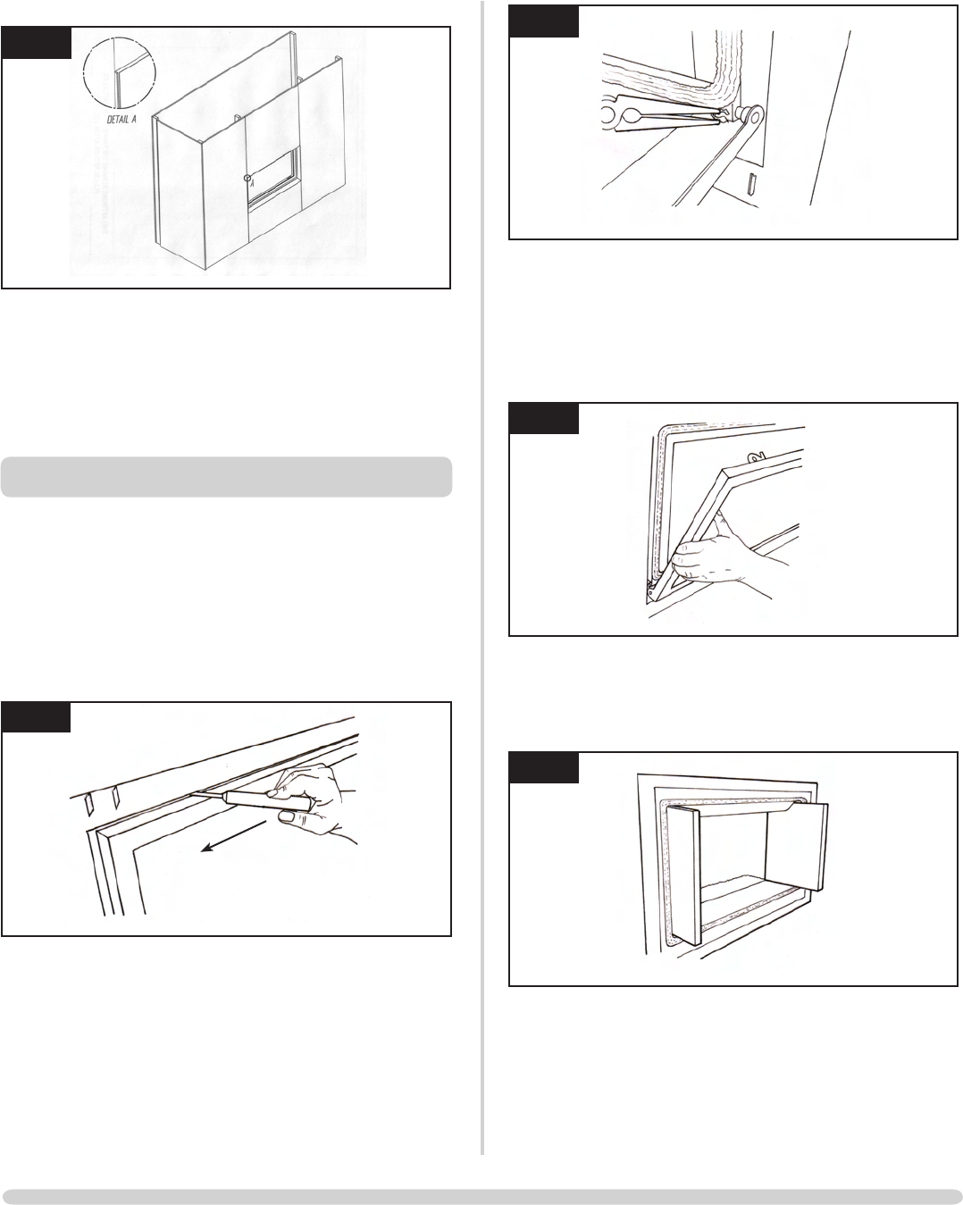
3. WINDOW FRAME ASSEMBLY
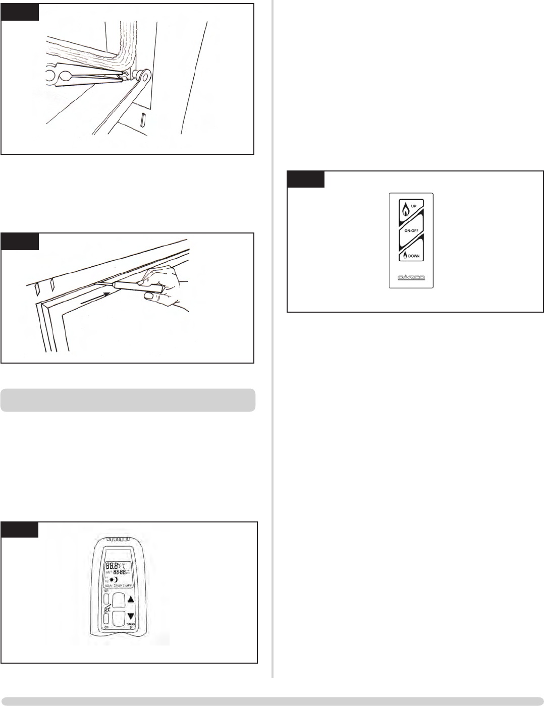
3.1 To open the glass door, use the allen key provided:
The lock needs to be moved from shut to open towards the
outer edges, Diagram 2
2
AR1860
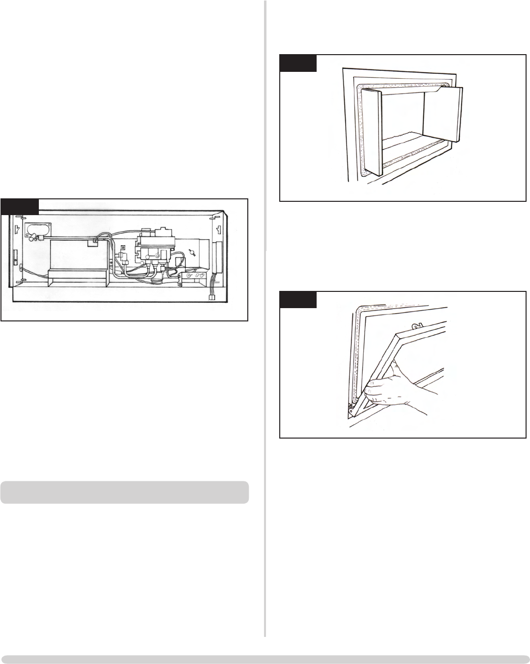
3.2 To completely remove the glass front:
the window frame, Diagram 3
SERVICING INSTRUCTIONS
REPLACING PARTS
26
SERVICING INSTRUCTIONS
REPLACING PARTS
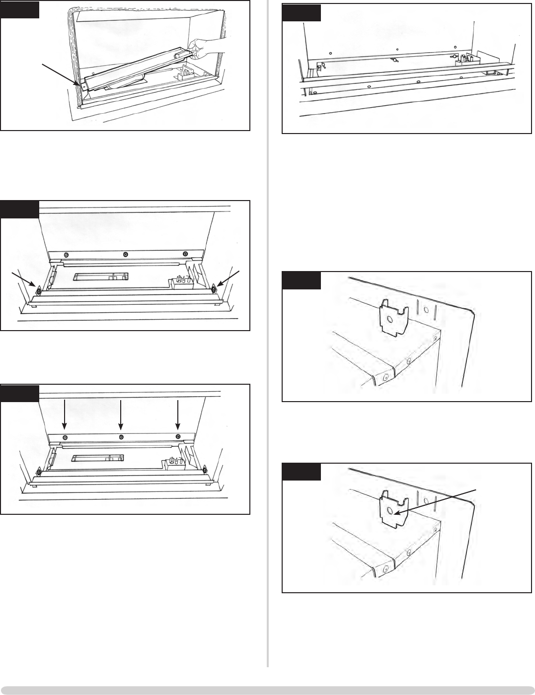
4. GLASS WINDOW
4.1 Remove the two clips and brackets from either side of the
frame, Diagram 5
5
AR1864
frame and slide out
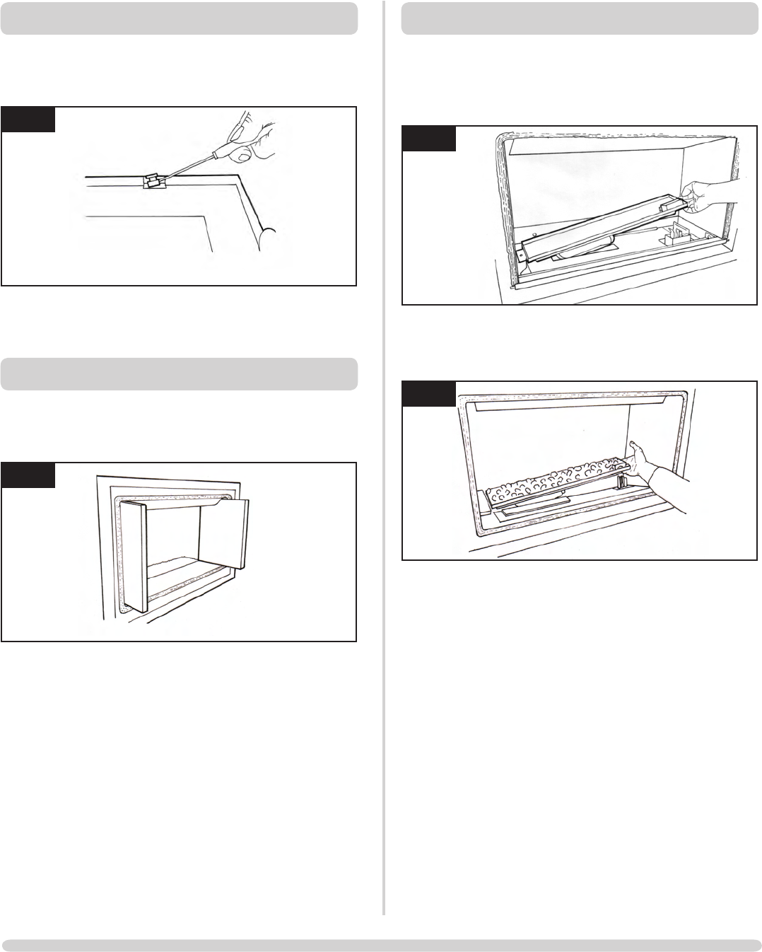
5. BLACK ENAMELLED PANELS
5.1 Hold the rear panel while sliding the side panels forward
until clear of the appliance, Diagram 6
6
AR1865
support rail
5.3 To reassemble the panels in reverse order:
place before the top edge is pushed back
6. MAIN BURNER
6.1 To replace the main burner:
the burner, Diagram 7
7
AR1965
8
AR1868
burner tray and flatten until level.
Ensure no stone pebbles fall into the pilot area.
7. MAIN CONTROL ASSEMBLY
7.1 To access the main control assembly, first remove:
7.2 To remove the splitter plater:
9
AR1966
All components can be replaced without removing the
control assembly.
8. PILOT UNIT ASSEMBLY
10
AR1963
disconnect the ignition lead from the electrode
27
11
AR0097
13mm
4.0mm
sleeve which is needed for the replacement
through the vida flex and secured with a cable tie
There is a cut out in the pilot shroud to hold the vida flex.
9. IGNITION LEAD
the ignition lead from the electrode
the control box, Diagram 12
12
AR1963
with a cable tie and the red insulated end is attached to the
electrode
NOTE: DO NOT ROUTE THE IGNITION LEAD IN THE
VICINITY OF THE ANTENNA ON THE CONTROL BOX.
THIS DAMAGES THE COMPONENTS.
SERVICING INSTRUCTIONS
REPLACING PARTS
28
SERVICING INSTRUCTIONS
REPLACING PARTS
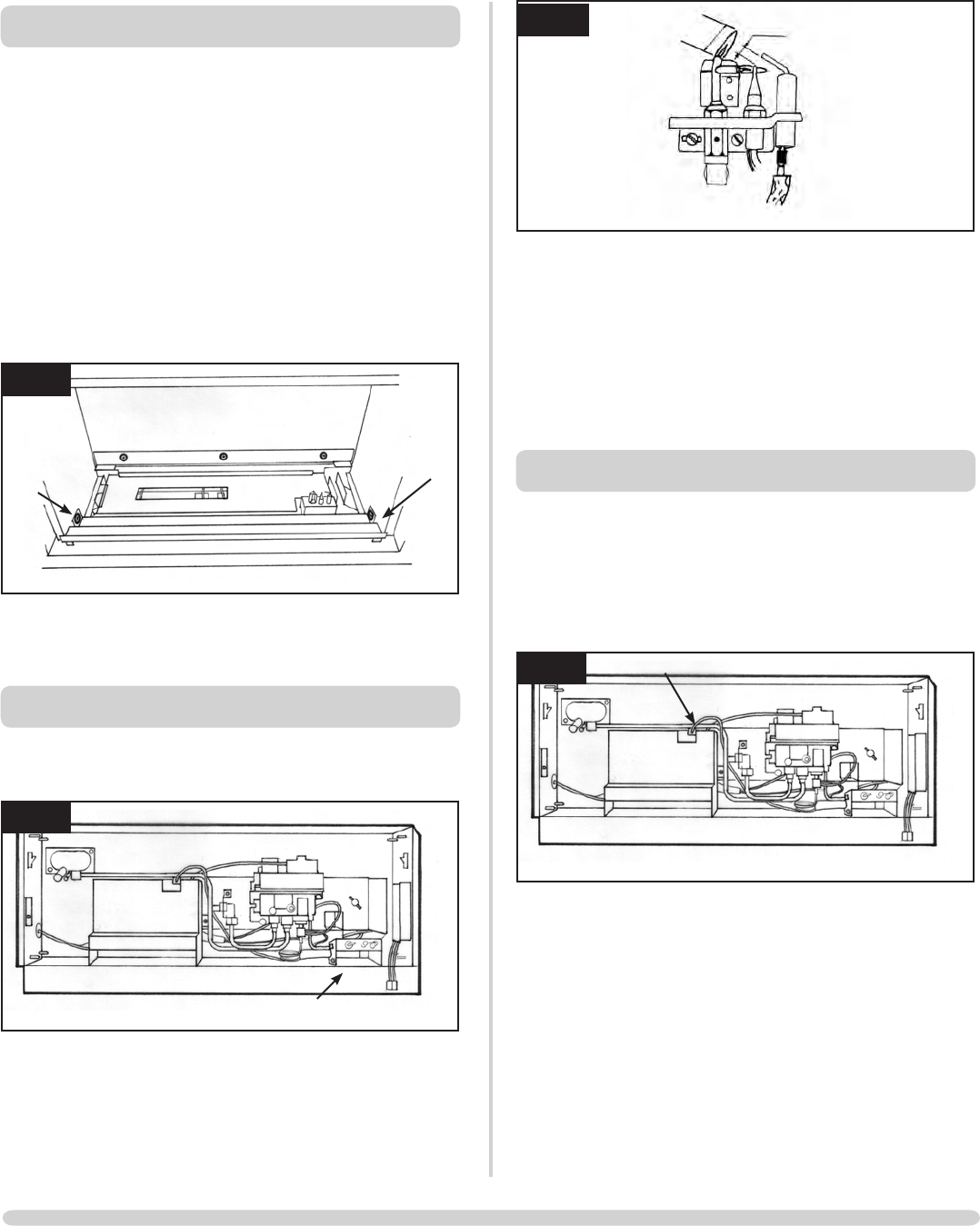
10. GAS VALVE
10.1 To change the gas valve:
the interrupter block
access the front
The cable can now be removed from the valve, Diagram 13
13
AR1963
11. MAGNETIC SAFETY VALVE
11.1 To replace the magnetic safety valve:
remove the two thermo current cables
of the valve.
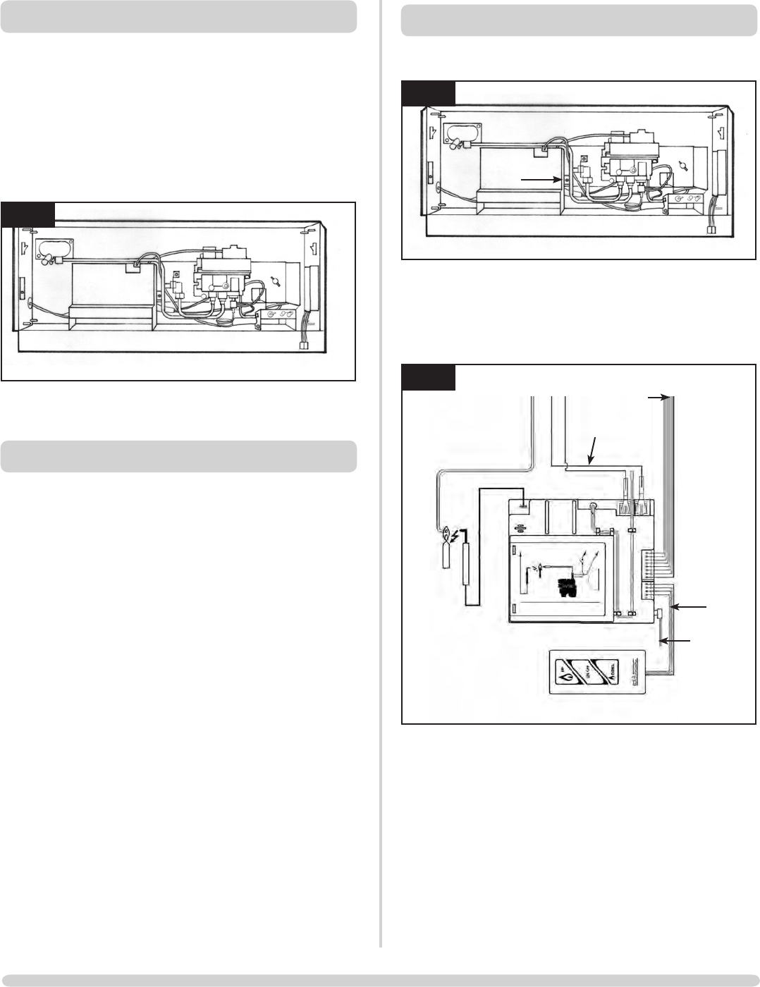
12. CONTROL BOX
14
AR1963
two screws, Diagram 15
Diagram 15
15
AR1915
Touch pad
extension
cable
Battery
extension
cable
cable
Thermo current
cables
Ignition lead
The control box can now be replaced.
After replacing the control box you may need to reprogram
the handset:
you hear two signals. After the second longer signal:
seconds
you hear an additional long signal
confirming the new code
29
SERVICING INSTRUCTIONS
REPLACING PARTS
13. MAIN INJECTOR
silencer
14. PRIMARY AERATION PLATE
9.1 Remove the burner module as described in Replacing Parts
Section 6.
9.2 Remove the fixing screw and slide the plate off the venturi.
9.3 Replace with the correct size plate and secure with the
the venturi flange, Diagram 16.
16
AR0766
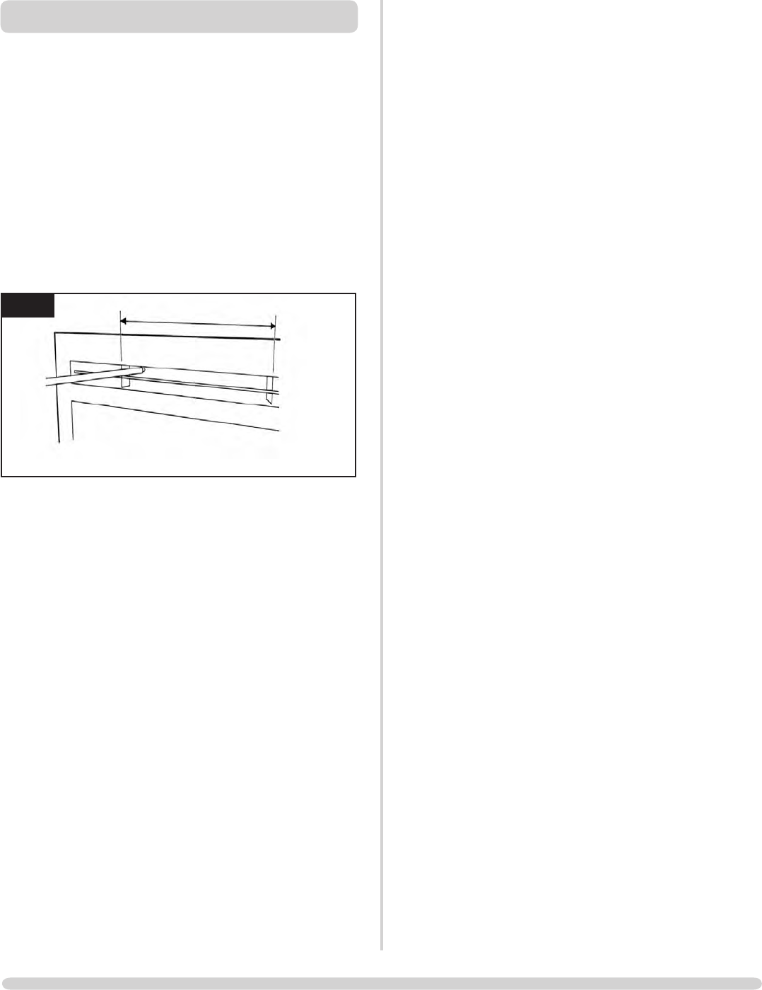
15. DEBRIS AREA ACCESS
appliance
box, Diagram 17
17
AR1967
17
Diagram 17
To release the box from the main body:
forward off the rear studs
base of the box
Any debris can now be removed through the aperture.
gas pipe when replacing the box
16. CHANGING BETWEEN
GAS TYPES
In order to change between gas types, it will be necessary to
change the following items:
Burner Unit
Pilot
Control Valve
Injector
Aeration Plate (if required)
Data badge
A kit of parts is available for this, always quote the Model
number and Serial number when ordering any spare parts.
NOTE: THE CONTROL VALVE IS FACTORY PRESET FOR
THE CORRECT GAS TYPE AND MODEL, A NEW UNIT
WILL NEED TO BE ORDERED WHEN CHANGING
BETWEEN GAS TYPES.

30
SERVICING INSTRUCTIONS
REPLACING PARTS
17. PRESSURE AND LEAK TESTING THE
APPLIANCE
14.1 Follow Section 7, Main Control Assembly, 7.1 and 7.2
Diagram 18
18
AR1963
Refer to paragraph 4.11 of the Installation Instructions to
check gas pressure
detector fluid
31
SERVICING INSTRUCTIONS
REPLACING PARTS
18. SHORT SPARES LIST
Studio 1 CF Studio 2 CF
COMPONENT NG LPG NG LPG
PILOT PI0036 PI0037 PI0036 PI0037
MAIN INJECTOR IN0028 IN0040 IN0029 IN0041
BURNER ASSEMBLY GZ6714 GZ6759 GZ6861 GZ6860
AERATION PLATE G20 - GZ3869 G30 - N/A G20-GZ3868 G30 - N/A
G25 - GZ4333 G31 - N/A G25 - GZ3270 G31 - GZ3866
MAG UNIT GC0092 GC0092
IGNITION LEAD GC0125 GC0125
GAS VALVE GC0123 GC0123
CONTROL BOX GC0129 GC0129
REMOTE CONTROL GC0131 GC0131
INTERRUPTER BLOCK GC0124 GC0124
THERMO CURRENT CABLE GC0126 GC0126
THERMO CURRENT CABLE
SWITCH
GC0128 GC0128
TOUCH PAD AND LEAD GC0130 GC0130
BATTERY HOLDER EL0410 EL0410
BATTERY HOLDER CABLE GC0127 GC0127
CONTROL BOX/VALVE CABLE GC0133 GC0133
REAR ENAMELLED PANEL GZ6488 GZ6867
SIDE ENAMELLED PANEL GZ6489 GZ6489
BASE ENAMELLED PANEL GZ6490 GZ6866
STONE PEBBLES CE0647 CE0579

32
SERVICE RECORDS
1ST SERVICE
Date of Service:...........................................................................
Next Service Due:.......................................................................
Signed:........................................................................................
3RD SERVICE
Date of Service:...........................................................................
Next Service Due:.......................................................................
.
Signed:........................................................................................
5TH SERVICE
Date of Service:...........................................................................
Next Service Due:.......................................................................
Signed:........................................................................................
7TH SERVICE
Date of Service:...........................................................................
Next Service Due:.......................................................................
Signed:........................................................................................
9TH SERVICE
Date of Service:...........................................................................
Next Service Due:.......................................................................
Signed:........................................................................................
2ND SERVICE
Date of Service:...........................................................................
Next Service Due:.......................................................................
Signed:........................................................................................
4TH SERVICE
Date of Service:...........................................................................
Next Service Due:.......................................................................
Signed:........................................................................................
6TH SERVICE
Date of Service:...........................................................................
Next Service Due:.......................................................................
Signed:........................................................................................
8TH SERVICE
Date of Service:...........................................................................
Next Due:........................................................................
Signed:........................................................................................
10TH SERVICE
Date of Service:...........................................................................
Next Service Due:.......................................................................
Signed:........................................................................................
Gazco Limited, Osprey Road, Sowton Industrial Estate, Exeter, Devon, England EX2 7JG
Tel: (01392) 261999 Fax: (01392) 444148 E-mail: info@gazco.com
A member of the Stovax Group
