Stow Cms 9 Users Manual REV 6.PMD
cms-9 to the manual 8b58b102-6d0b-4859-8389-7a0a292d5d71
2015-02-02
: Stow Stow-Cms-9-Users-Manual-489453 stow-cms-9-users-manual-489453 stow pdf
Open the PDF directly: View PDF ![]() .
.
Page Count: 84

OPERATION AND PARTS MANUAL
CMS-9
CONCRETE MIXER
PARTS DEPARTMENT:
800-427-1244
FAX: 800-672-7877
SERVICE DEPARTMENT/TECHNICAL ASSISTANCE:
800-478-1244
FAX: 310-631-5032
STOW CONSTRUCTION EQUIPMENT
A DIVISION OF MULTIQUIP INC.
POST OFFICE BOX 6254
CARSON, CA 90749
310-537-3700 • 888-252-STOW [888-252-7869]
FAX: 310-537-1986 • FAX: 800-556-1986
E-MAIL: STOW@multiquip.com • WWW: stowmfg.com
Revision #6 (01/08/07)
Engine exhaust and some of
its constituents, and some dust created
of California to cause cancer, birth
defects and other reproductive harm.
by power sanding, sawing, grinding,
drillingandotherconstructionactivities
contains chemicals known to the State
Some examples of these chemicals are:
Leadfromlead-basedpaints.
Crystallinesilicafrombricks.
Cementandothermasonryproducts.
Arsenicandchromiumfromchemically
treatedlumber.
Your risk from these exposures varies,
dependingonhowoftenyoudothistype
of work. To reduce your exposure to
these chemicals: work in aALWAYS
well ventilated area, and work with
approved safety equipment, such as
dust masks that are specially designed
to filter out microscopic particles.

STOW CMS-9S CONCRETE MIXER — PARTS & OPERATION MANUAL — REV. #6 (01/08/07) — PAGE 3
NOTE PAGE

PAGE 4 — STOW CMS-9S CONCRETE MIXERS — PARTS & OPERATION MANUAL — REV. #6 (01/08/07)
STOW CMS-9S CONCRETE MIXER — TABLE OF CONTENTS
Componet Drawings
Nameplate and Decals....................................... 34-35
Mixer Assembly (Steel Drum) ............................ 36-37
Mixer Assembly (Plastic Drum) .......................... 38-39
Main Frame Assembly ....................................... 40-41
Axle Assembly .................................................... 42-43
Cabinet Assembly .............................................. 44-45
Gas Engine Mounting Plate Asasembly ............ 46-47
Electric Motor Mounting Plate Asasembly ........ 48-49
Specification and part number
are subject to change without
notice.
NOTE
STOW CMS-9S Concrete
Mixer
Here's How To Get Help ............................................ 3
Table Of Contents ..................................................... 4
Parts Ordering Procedures ....................................... 5
Specifications ............................................................ 6
Dimensions (Mixer) ................................................... 7
Safety Message Alert Symbols ................................. 8
Rules For Safe Operation .................................... 9-10
Operation and Safety Decals .................................. 11
General Information ................................................ 12
Mixer Basic Components ........................................ 13
Basic Engine Components ...................................... 14
Handwheel Assembly .............................................. 15
Towing Guidelines ................................................... 16
Safety Chain Connection ........................................ 17
Electric Motor ..................................................... 18-19
Pre-Inspection (Gasoline Engine) ........................... 20
Initial Start-up (Gasoline Engine)............................ 21
Initial Start-up (Electric Motor) ................................ 22
Operation ................................................................ 23
Maintenance (Engine)........................................ 24-25
Maintenance (Mixer) .......................................... 26-28
Troubleshooting (Engine) ........................................ 30
Troubleshooting (Engine/Mixer) .............................. 31
Explanation Of Code In Remarks Column .............. 32
Suggested Spare Parts ........................................... 33
HONDA GX240K1HA2 ENGINE
Air Cleaner Assembly......................................... 50-51
Camshaft Assembly ........................................... 52-53
Carburetor Assembly ......................................... 54-55
Control Assembly ............................................... 56-57
Crankcase Cover Assembly ............................... 58-59
Crankshaft Assembly ......................................... 60-61
Cylinder Barrel Assembly ................................... 62-63
Cylinder Head Assembly .................................... 64-65
Fan Cover Assembly .......................................... 66-67
Flywheel Assembly ............................................ 68-69
Muffler Assembly ............................................... 70-71
Fuel Tank Assembly ........................................... 72-73
Ignition Coil ........................................................ 74-75
Piston Assembly ................................................. 76-77
Recoil Starter ..................................................... 78-79
Gear Reduction Assembly ................................. 80-81
Label Assembly .................................................. 82-83
Terms and Conditions of Sale ................................. 84
STOW CMS-9S CONCRETE MIXER — PARTS & OPERATION MANUAL — REV. #6 (01/08/07) — PAGE 5
STOW CMS-9S CONCRETE MIXER — PARTS ORDERING PROCEDURES
When ordering parts,
please supply the following information:
❒❒
❒❒
❒Dealer account number
❒❒
❒❒
❒Dealer name and address
❒❒
❒❒
❒Shipping address (if different than billing address)
❒❒
❒❒
❒Return fax number
❒❒
❒❒
❒Applicable model number
❒❒
❒❒
❒Quantity, part number and description of each part
❒❒
❒❒
❒Specify preferred method of shipment:
✓FedEx or UPS Ground
✓FedEx or UPS Second Day or Third Day
✓FedEx or UPS Next Day
✓Federal Express Priority One
✓DHL
✓Tr u ck
Here’s how to get help...
Please have the model and serial number on
hand when calling.
Parts Department
800-427-1244 Fax: 800-672-7877
310-537-3700 Fax: 310-637-3284
Mayco Parts
800-306-2926 Fax: 800-672-7877
310-537-3700 Fax: 310-637-3284
Service Department
800-478-1244 Fax: 310-537-4259
310-537-3700
MQ Power Service Department
800-835-2551 Fax: 310-638-8046
310-537-3700
Technical Assistance
800-478-1244 Fax: 310-631-5032
Warranty Department
800-421-1244, Ext. 279 Fax: 310-537-1173
310-537-3700, Ext. 279
Multiquip’s Main Phone Numbers
800-421-1244 Fax: 310-537-3927
310-537-3700
Note: Unless otherwise indicated by customer, all
orders are treated as “Standard Orders”, and will
ship within 24 hours. We will make every effort to
ship “Air Shipments” the same day that the order is
received, if prior to 2PM west coast time. “Stock
Orders” must be so noted on fax or web forms.
Extra Discounts!
All parts orders which include complete part numbers
and are received by our automated web parts order
system, or by fax qualify for the following extra
discounts:
Ordered Standard Stock orders
via orders ($750 list and above)
Fax 3% 10%
Web 5% 10%
Special freight allowances
when you order 10 or more
line items via Web or Fax!**
FedEx Ground Service
at no charge for freight
No other allowances on freight shipped by any other
carrier.
Place Your Parts Order Via Web or Fax
For Even More Savings!
NOTE: DISCOUNTS ARE SUBJECT TO CHANGE
Direct TOLL-FREE access
to our Parts Department:
Toll-free nationwide — 800-427-1244
STOW CONSTRUCTION EQUIPMENTSTOW CONSTRUCTION EQUIPMENT
STOW CONSTRUCTION EQUIPMENTSTOW CONSTRUCTION EQUIPMENT
STOW CONSTRUCTION EQUIPMENT
A DIVISION OF MULTIQUIP INC.
POST OFFICE BOX 6254
CARSON, CA 90749
310-537-3700 • 888-252-STOW [888-252-7869]
FAX: 310-537-1986 • FAX: 800-556-1986
E-MAIL: stow@multiquip.com • WWW: stowmfg.com
PAGE 6 — STOW CMS-9S CONCRETE MIXERS — PARTS & OPERATION MANUAL — REV. #6 (01/08/07)
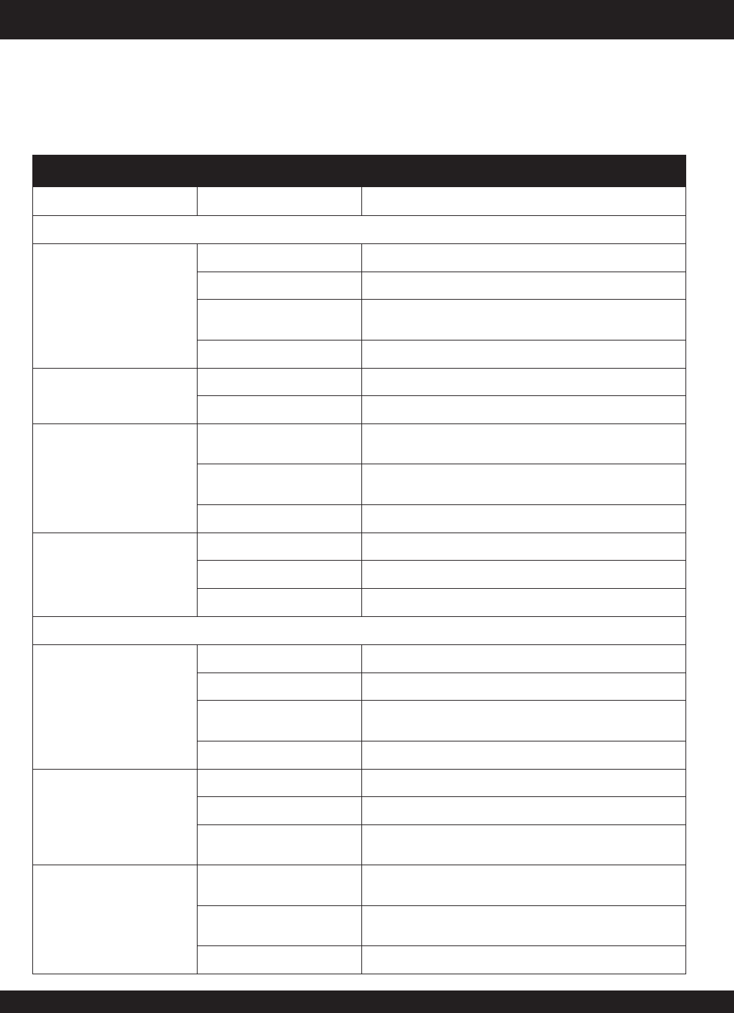
STOW CMS-9S CONCRETE MIXER — SPECIFICATIONS
)rotoMcirtcelE/senignE(snoitacificepS.1elbaT
cirtcelE/enignE
rotoM
ledoM2AH1K042XGADNOH000RY252-HENIBOR922LYL53rodlaB
epyT ,rednilyCelgniS,ekorts4delooc-
riA
enignEenilosaGtfahSlatnoziroH,VHO
,rednilyCelgniS,ekorts4delooc-riA
enignEenilosaGtfahSlatnoziroH,VH
O
032/511esahp-elgniS,PH5.1
rotoMcirtcelE,CAV
ekortSXeroB .ni03.2X.ni09.2
)mm85xmm37(
.ni42.2X.ni59.2
)mm75x
mm57( A/N
tnemecalpsiDcc18.41cc13.51A/N
tuptuOxaM.M.P.R0063/.P.H0.8.M.P.R0004/.P.H5.8.M.P.R5271/PH5.1
yticapaCk
naTleuF snollaG.S.U95.1.xorppA
)sretiL6(
snollaG.S.U95.1.xorppA
)sretiL6( A/N
leuFenilosaGdedaelnUenilosaGdedaelnUA/N
yticapaCliOebuLstnip3/1-2stnip2A/N
lortnoCdeepS
dohteM epyTthgiew-ylFlagufirtneCepyTthgiew-ylFlagufir
tneCA/N
dohteMgnitratStratSlioceRtratSlioceRcirtcelE
egatloVtupnIA/NA/NesahPelgniSCAV032/511
noisnemiD
)HxWxL(
.n
i1.61X9.61x0.41
)mm014X034X553(
.ni23.71X02.61x04.41
)mm044X214X663(
.ni60.9X56.8x55.51
)mm032X022X593(
thg
ieWteNyrD ).gK52(sbl1.55).gK32(sbl7.05).gk4.5(sbl21.xorppA
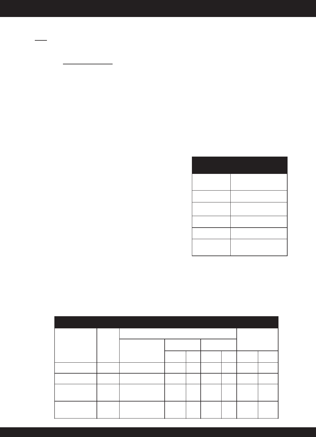
snoitacificepSS9-SMC.2elbaT
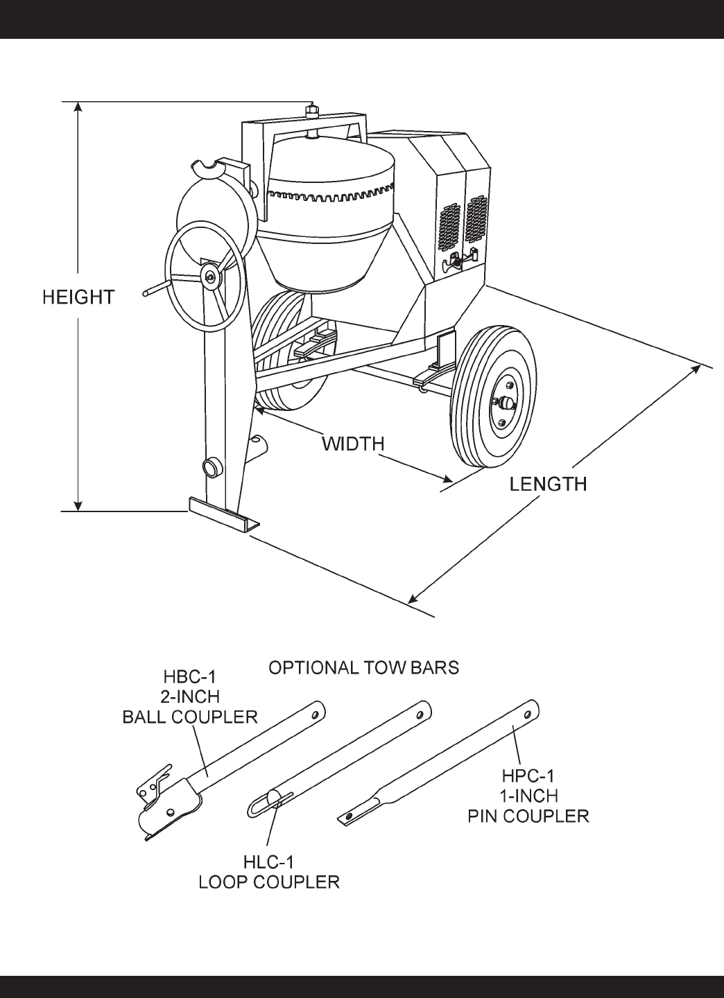
thgieH )mm006,1(.ni36
htdiW )mm592,1(.ni15
htgneL )mm581,2(.ni68
yticapaCmurDmumixaM )sretil053(.tf.uc53.21
yticapaCgnixiMmumixaM )sretil552(.tf.uc0.9
yticapaCgaB sgaB5.1~1
rotoMcirtcelE/enignEtuohtiW-thgieW ).gK243(.sbl557
STOW CMS-9S CONCRETE MIXER — PARTS & OPERATION MANUAL — REV. #6 (01/08/07) — PAGE 7
STOW CMS-9S CONCRETE MIXER — DIMENSIONS (MIXER)
See Table 2 for mixer dimensions
Figure 1. Mixer Dimensions
PAGE 8 — STOW CMS-9S CONCRETE MIXERS — PARTS & OPERATION MANUAL — REV. #6 (01/08/07)
Accidental Starting
ALWAYS place the circuit breaker or power
ON/OFF switch in the OFF position when the
pump is not in use.
Respiratory Hazard
ALWAYS wear approved respiratory
protection.
Equipment Damage Messages
Other important messages are provided throughout this manual
to help prevent damage to your mixer, other property, or the
surrounding environment.
ALWAYS wear approved eye and hearing
protection.
Sight and Hearing hazard
STOW CMS-9S CONCRETE MIXER — SAFETY MESSAGE ALERT
SYMBOLS
Safety precautions should be followed at all times when
operating this equipment. Failure to read and understand the
Safety Messages and Operating Instructions could result in
injury to yourself and others.
FOR YOUR SAFETY AND THE SAFETY OF OTHERS!
This Owner's Manual has been
developed to provide complete
instructions for the safe and
efficient operation of the
STOW
Model CMS-9S (Steel) Concrete
Mixer.
Before using this mixer, ensure
that the operating individual
has read and understands all
instructions in this manual.
SAFETY MESSAGE ALERT SYMBOLS
The three (3) Safety Messages shown below will inform you
about potential hazards that could injure you or others. The
Safety Messages specifically address the level of exposure to
the operator, and are preceded by one of three words: DANGER,
WARNING, or CAUTION.
DANGER: You WILL be KILLED or
SERIOUSLY injured if you do not follow
directions.
WARNING: You CAN be KILLED or
SERIOUSLY injured if you do not follow
directions.
CAUTION: You CAN be injured if you
do not follow directions.
HAZARD SYMBOLS
Potential hazards associated with the stow CMS-9S concrete
mixer operation will be referenced with Hazard Symbols which
appear throughout this manual, and will be referenced in
conjunction with Safety Message Alert Symbols.
Rotating Parts
NEVER operate equipment with covers, or
guards removed. Keep fingers, hands, hair and
clothing away from all moving parts to prevent
injury.
NOTE
This mixer, other property, or the
surrounding environment could
be damaged if you do not follow
instructions.
NOTE
STOW CMS-9S CONCRETE MIXER — PARTS & OPERATION MANUAL — REV. #6 (01/08/07) — PAGE 9
STOW CMS-9S CONCRETE MIXER — RULES FOR SAFE OPERATION
■
ALWAYS refuel in a well-ventilated area, away from sparks
and open flames.
■
ALWAYS use extreme caution when working with flammable
liquids. When refueling, stop the engine and allow it to cool.
DO NOT smoke around or near the machine. Fire or explosion
could result from fuel vapors, or if fuel is spilled on a hot
engine.
■
NEVER operate the mixer in an explosive
atmosphere or near combustible
materials. An explosion or fire could result
causing severe
bodily harm or even
death.
■
Topping-off to filler port is dangerous, as it tends to spill fuel.
■
Refer to the
Engine Owner's Manual
for engine technical
questions or information.
■
NEVER use accessories or attachments, which are not
recommended by STOW for this equipment. Damage to the
equipment and/or injury to user may result.
■
Manufacturer does not assume responsibility for any accident
due to equipment modifications.
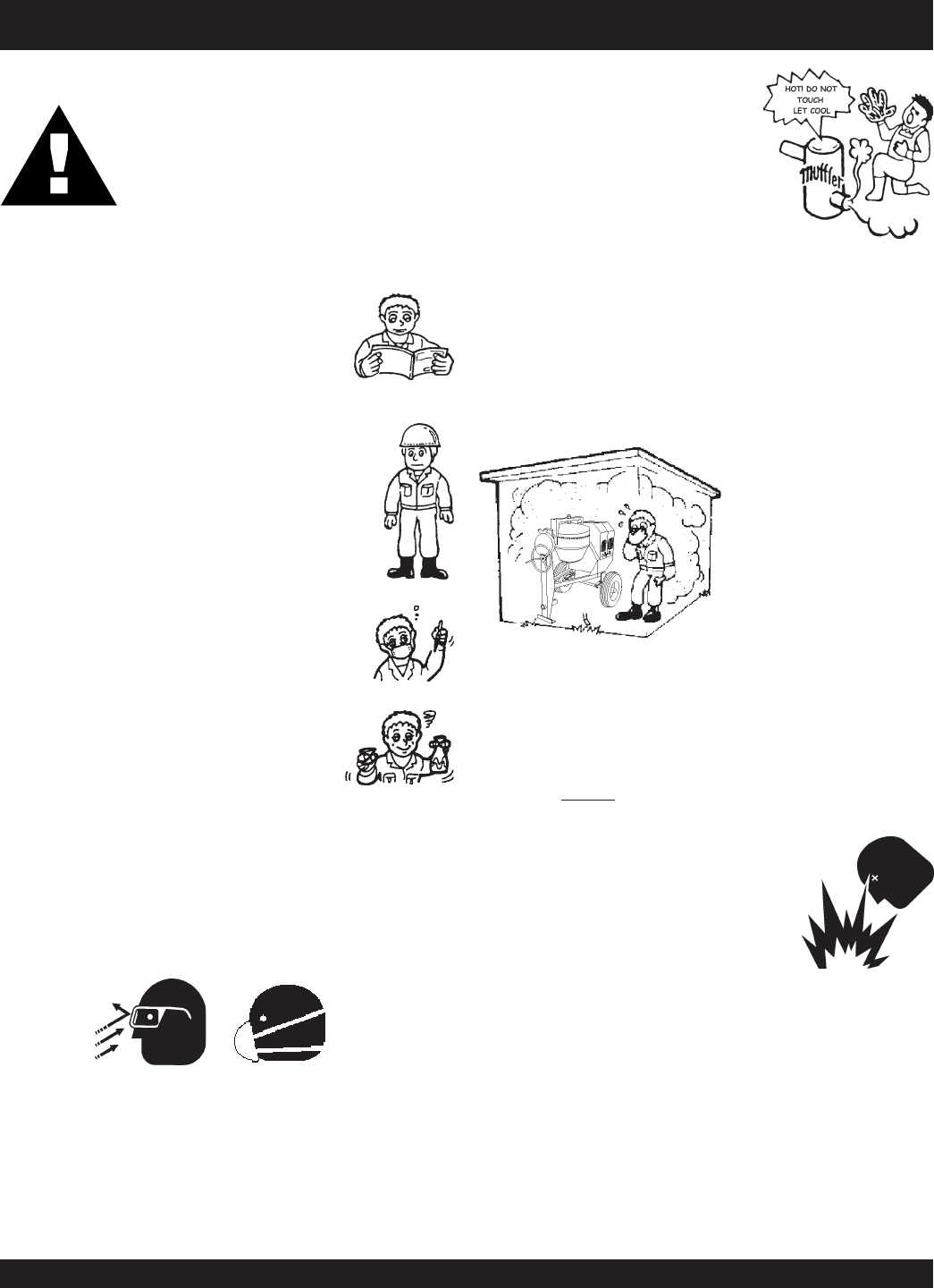
■
NEVER touch the hot exhaust manifold,
muffler or cylinder. Allow these parts to
cool before servicing engine or mixer.
■
The engine of this mixer requires an adequate free flow of
cooling air.
NEVER!
operate the mixer in any enclosed or
narrow area where free
flow of the air is restricted. If
the air flow is restricted it
will cause serious damage
to the mixer or engine and
may cause injury to people
and property. Remember
the mixer's engine
(gasoline models only)
gives off DEADLY gases.
■
High Temperatures – Allow the engine to cool before adding
fuel or performing service and maintenance functions. Contact
with
hot
components can cause serious burns.
DANGER:
Failure to follow instructions in this manual may
lead to serious injury or even death! This
equipment is to be operated by trained and
qualified personnel only! This equipment is for
industrial use only.
The following safety guidelines should always be used when
operating the STOW CMS-9S Concrete Mixer:
GENERAL SAFETY
■
DO NOT operate or service this equipment before
reading this entire manual.
■
This equipment should not be operated by
persons under 18 years of age.
■
NEVER operate this equipment without proper
protective clothing, shatterproof glasses, steel-
toed boots and other protective devices required
by the job.
■
NEVER operate this equipment when not feeling
well due to fatigue, illness or taking medicine.
■
NEVER operate this equipment under the
influence or drugs or alcohol.
■
Whenever necessary, replace nameplate, operation and
safety decals when they become difficult read.
■
ALWAYS check the machine for loosened threads or bolts
before starting.
■
ALWAYS wear proper respiratory (mask) hearing and eye
protection equipment when operating the mixer.
■
NEVER!
place hands inside the drum while the drum is
rotating.
PAGE 10 — STOW CMS-9S CONCRETE MIXERS — PARTS & OPERATION MANUAL — REV. #6 (01/08/07)
■
In emergencies
always
know the location of the
nearest phone or
keep a phone on the job site
.
Also know the phone numbers of the nearest
ambulance
,
doctor
and
fire department
. This
information will be invaluable in the case of an
emergency.
■
NEVER disconnect any
"emergency or safety devices"
.
These devices are intended for operator safety. Disconnection
of these devices can cause severe injury, bodily harm or even
death! Disconnection of any of these devices will void all
warranties.
■
If mixer is equipped with an electric motor, operate electric
motor only at the specified voltage indicated on the nameplate.
■
Make sure the
OFF/ON
power switch on the electric motor is
always
in the
OFF
position before inserting the mixer's power
plug into an AC receptacle (electric model only).
Maintenance Safety
■
NEVER lubricate components or attempt service on a running
machine.
■
ALWAYS allow the machine a proper amount of time to cool
before servicing.
■
Keep the machinery in proper running condition.
■
Fix damage to the machine immediately and always replace
broken parts, or missing decals.
■
Dispose of hazardous waste properly. Examples of potentially
hazardous waste are used motor oil, fuel and fuel filters.
■
DO NOT use food or plastic containers to dispose of
hazardous waste.
■
DO NOT pour waste, oil or fuel directly onto the ground,
down a drain or into any water source.
Emergencies
■
ALWAYS know the location of the nearest
fire extinguisher
and first aid kit.
STOW CMS-9S CONCRETE MIXER — RULES FOR SAFE OPERATION
■
NEVER run engine without air cleaner. Severe engine damage
may occur.
■
ALWAYS read, understand, and follow procedures in
Operator’s Manual before attempting to operate equipment.
■
ALWAYS be sure the operator is familiar with proper safety
precautions and operations techniques before using roller.
■
ALWAYS store equipment properly when it is not being used.
Equipment should be stored in a clean, dry location out of the
reach of children.
■
NEVER leave the mixer unattended, turn off engine or electric
motor when unattended.
■
CAUTION must always be observed while servicing this mixer.
Rotating parts can cause injury if contacted.
■
Unauthorized equipment modifications will void all
warranties.
■
Ensure that any extension cable is protected against damage
and not liable to be tripped over or trapped underneath the
mixer.
■
DO NOT allow extension cord to come into contact with water
or fluids.
■
DO NOT spray water onto electric motor.
■
This mixer is intended for the production of concrete. Mixer
must be used only for its intended purpose.
■
This mixer is not suitable for the mixing of
flammable
or
explosive
substances.
■
NEVER operate the mixer in an
explosive
atmosphere.
■
Before starting the mixer, check that all
guards
are in position
and correctly fitted.
■
Keep area around the mixer
clear of obstructions
which
could cause persons to fall onto
moving parts
.
■
ALWAYS ensure mixer is on level ground before mixing.
■
Become familiar with the controls of the mixer before
operating.
■
ALWAYS replace any worn or damaged warning decals.
■
Ensure the drum is
rotating
while filling and emptying the
drum.
■
ALWAYS disconnect AC power plug from power source
before moving mixer (electric model only).
■
High Temperatures – Always stop engine and allow the
engine to cool before adding fuel, oil or performing service
and maintenance functions. Contact with
hot
components
can cause serious burns.
STOW CMS-9S CONCRETE MIXER — PARTS & OPERATION MANUAL — REV. #6 (01/08/07) — PAGE 11
STOW CMS-9S CONCRETE MIXER — OPERATION AND SAFETY DECALS
Machine Safety Decals
The STOW CMS-9S mixer is equipped with a number of safety decals (Figure 1A). These decals are provided for operator safety
and maintenance information. The illustration below and on the next page shows these decals as they appear on the machine.
Should any of these decals become unreadable, replacements can be obtained from your dealer.
Figure 1A. STOW CMS-9S Mixer Decals
PAGE 12 — STOW CMS-9S CONCRETE MIXERS — PARTS & OPERATION MANUAL — REV. #6 (01/08/07)
STOW CMS-9S CONCRETE MIXER — GENERAL INFORMATION
Application
This mixer is
only
intended for the production of
concrete
.
The mixer must be used for its intended purpose and is not
suitable for the mixing of
flammable
or
explosive
substances. The mixer
must not be used
in an explosive
atmosphere. Use Table 4 (Mixing Hints) as a guide when
mixing concrete for various applications.
Power Plants
The STOW CMS-9S mixer can be powered by a variety of
power plants or an electric motor. Refer to Table 2 to for
specific engine or electric motor data information. All engines
are air-cooled, 4-stroke gasoline engines.
Electrical
If mixer is equipped with an
electric motor
, make sure that
the power being supplied to the motor corresponds to the
voltage rating label on the motor. Supplying the wrong voltage
to the electric motor will cause severe electrical damage to
the motor.
Always make sure the
OFF/ON
switch on the electric motor
is in the
OFF
position before applying power.
It is
strongly recommended
when inserting the mixer's
power cord into a receptacle, that a G.F.C.I. (
Ground Fault
Current
Interrupter
) receptacle be used (115 VAC
applications).
Extension Cables
The extension cable should be a 3-wire configuration that
includes a ground wire that conforms to UL code. The wire
cross section must be a minimum of 2.5 mm2 . Choose an
extension cord of adequate current carrying as Referenced
in Table 6. Remember
distance
affects the wire size of the
extension cable.
Ensure that the extension cable is carefully laid out avoid-
ing
wet areas
,
sharp edges
and locations where vehicles
might run over it. Avoid allowing the extension cable to be
trapped underneath the mixer.
Unroll the extension cable fully or it will overheat and could
catch fire. Make sure that all extension cable connections
are dry and safe. Replace any defective or badly worn ex-
tension cable immediately.
Hardware
Check all hardware on the mixer before starting. Periodically
inspect all hardware. Loose hardware can contribute to early
component failure and poor performance. Use Table 3 as general
guideline when the torqueing of mixer hardware is required.
Remember to keep all mixer hardware components tight.
Engine Maintenance
For basic engine maintenance, refer to the engine maintenance
section in this manual. For a more detailed engine maintenance,
refer to the
Honda
or
Robin
Engine Owner's manual furnished
with the engine.
euqroTerawdraH.3elbaT
noitadnemmoceR s
erawdraH
retemaiD )sbl-tf(euqroT
81xhcni-61/541
61xhcni-8/342
42xhcni-8/
373
31xhcni-2/193
31xhcni-2/1
)8edarG(
09
STNIHGNIXIM.4elbaT
SNOITACILPPA XIM
SOITAR
SEITITNAUQHCTAB
HCTAB.XORPPA
TUPTUO
.sbl211TNEMEC
).sgK05(
gaB
DNASENOTS
.TF.UCRTL.TF.UCRTL.
TF.UCRTL
yranidrOtsoM 4:2:1GAB2/14/1-1532/1-2173 58
snoitadnuoF 6:3:1GAB3/14/1-1532/1-2174/3-287
ssaMhguoR
etercnoC
8:4:1GAB4
/14/1-1532/1-2174/3-287
,sroolFthgitretaW
.ctE,stiP,sknaT
3:2/1-1:1GAB3/24/1-1533 173 58
STOW CMS-9S CONCRETE MIXER — PARTS & OPERATION MANUAL — REV. #6 (01/08/07) — PAGE 13
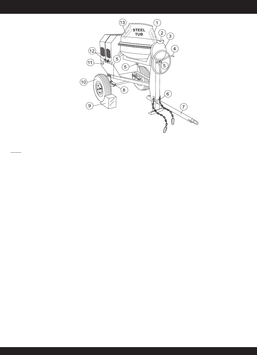
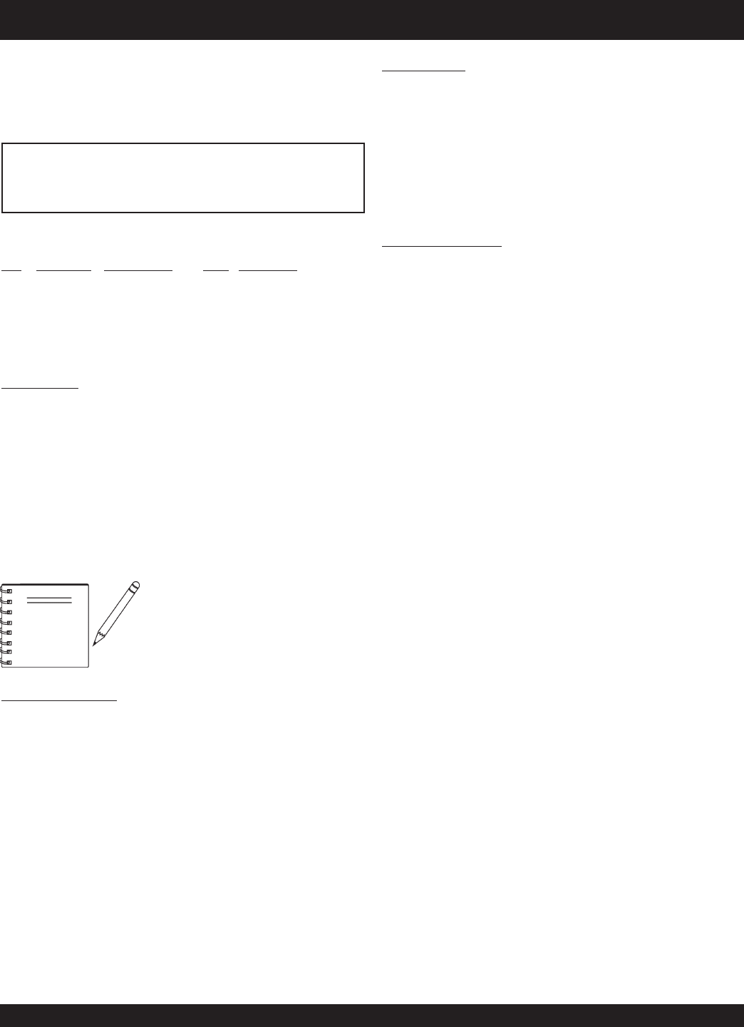
STOW CMS-9S CONCRETE MIXER — MIXER BASIC COMPONENTS
1. Steel Mixing Drum — The STOW CMS-4S uses a 4 cu. ft
steel
mixing drum. This drum is to be used for mixing of
concrete. Always clean the drum after each use. DO NOT
use this mixing drum for the mixing of volatile liquids.
2. Dump Latch — To rotate the mixing drum, this latch must
be in the up position. To lock the drum, place the latch in the
down position.
3. Dump Gear Guard — NEVER operate the mixer with this
guard removed. Its purpose is to prevent dirt and debris
from entering the dump gear. In addition operator clothing
could become entangled in the dump gear, causing severe
injury and bodily harm.
4. Handwheel — Turn this wheel clockwise or counter-
clockwise to rotate the mixing drum. Remember the dump
latch must be in the
up position
in order for the mixing
drum to be rotated.
5. Zerk Fittings — There is, at the bottom and engine side
of the yoke, and center of the
handwheel
grease zerk
fittings. Lubricate these fittings as referenced in the
maintenance section of this manual.
6. Safety Chain — This mixer uses a 3/16-inch thick, 72-
inches long zinc-plated saftey chain.
ALWAYS
connect the
safety chain when towing.
7. Tow Bar — This mixer uses various towing bars, please
reference the frame assembly drawing and parts list in this
manual to determine which tow bar meets your
requirements.
8. Leaf Suspension — This mixer uses a leaf type
suspension. Check the mounting hardware for bolt hole
elongation and tightness. See maintenance section of this
manual for recommended maintenance.
9. Chock Blocks — Place these blocks (not included as
part of the mixer package) under each mixer wheel to
prevent rolling, when mixer is not connect to the towing
vehicle.
10. Tires Ply — The tire ply (layers) number is rated in letters;
This mixer uses 13-inch 2-ply tires. Replace with only
recommended type tires.
11. ON/OFF Switch (gasoline only) — This switch is provided
on
mixerwith gasoline
engines only and is located on the
side of the mixer frame. When activated it will shut down
the engine. Pull out when starting the engine.
12. Cabinet/Latch — Encloses engine and electric motor.
NEVER run mixer with cabinet removed. Use latches to
secure engine compartment cabinet.
13. Mixing Blades (Steel) — Used for the mixing of concrete.
When blades show signs of wear, entire steel mixing drum
assembly must be replaced. See steel mixing drum
assembly in the parts section of this manual.
Figure 2. Mixer Major Components
PAGE 14 — STOW CMS-9S CONCRETE MIXERS — PARTS & OPERATION MANUAL — REV. #6 (01/08/07)
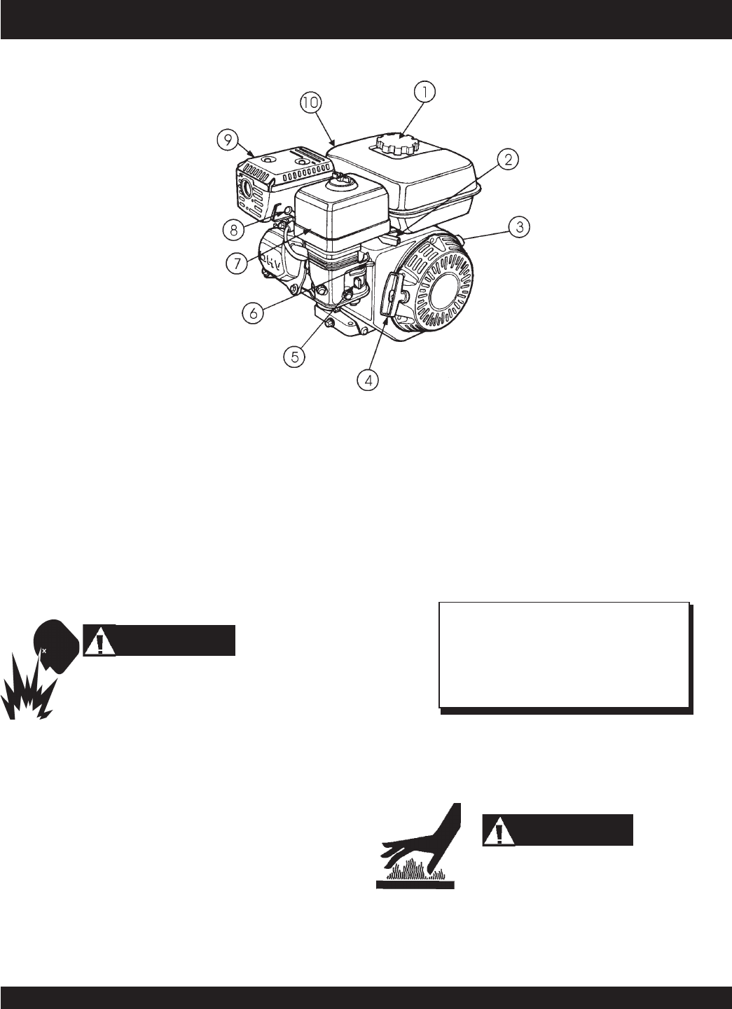
STOW CMS-9S CONCRETE MIXER — BASIC ENGINE COMPONENTS
Figure 3. Engine Controls and Components
INITIAL SERVICING
The engine (Figure 3) must be checked for proper lubrication and
filled with fuel prior to operation. Refer to the manufacturers Engine
manual for instructions & details of operation and servicing.
1. Fuel Filler Cap – Remove this cap to add unleaded
gasoline to the fuel tank. Make sure cap is tightened
securely. DO NOT over fill.
Adding fuel to the tank should be accomplished only
when the engine is stopped and has had an
opportunity to cool down. In the event of a fuel spill,
DO NOT attempt to start the engine until the fuel residue has been
completely wiped up, and the area surrounding the engine is dry.
2. Throttle Lever – Used to adjust engine RPM speed (lever
advanced forward
SLOW
, lever back toward operator
FAST
).
3. Engine ON/OFF Switch – ON position permits engine
starting, OFF position stops engine operations.
4. Recoil Starter (pull rope) – Manual-starting method. Pull
the starter grip until resistance is felt, then pull briskly and
smoothly.
5. Fuel Valve Lever – OPEN to let fuel flow, CLOSE to stop
the flow of fuel.
6. Choke Lever – Used in the starting of a cold engine, or in
cold weather conditions. The choke enriches the fuel
mixture.
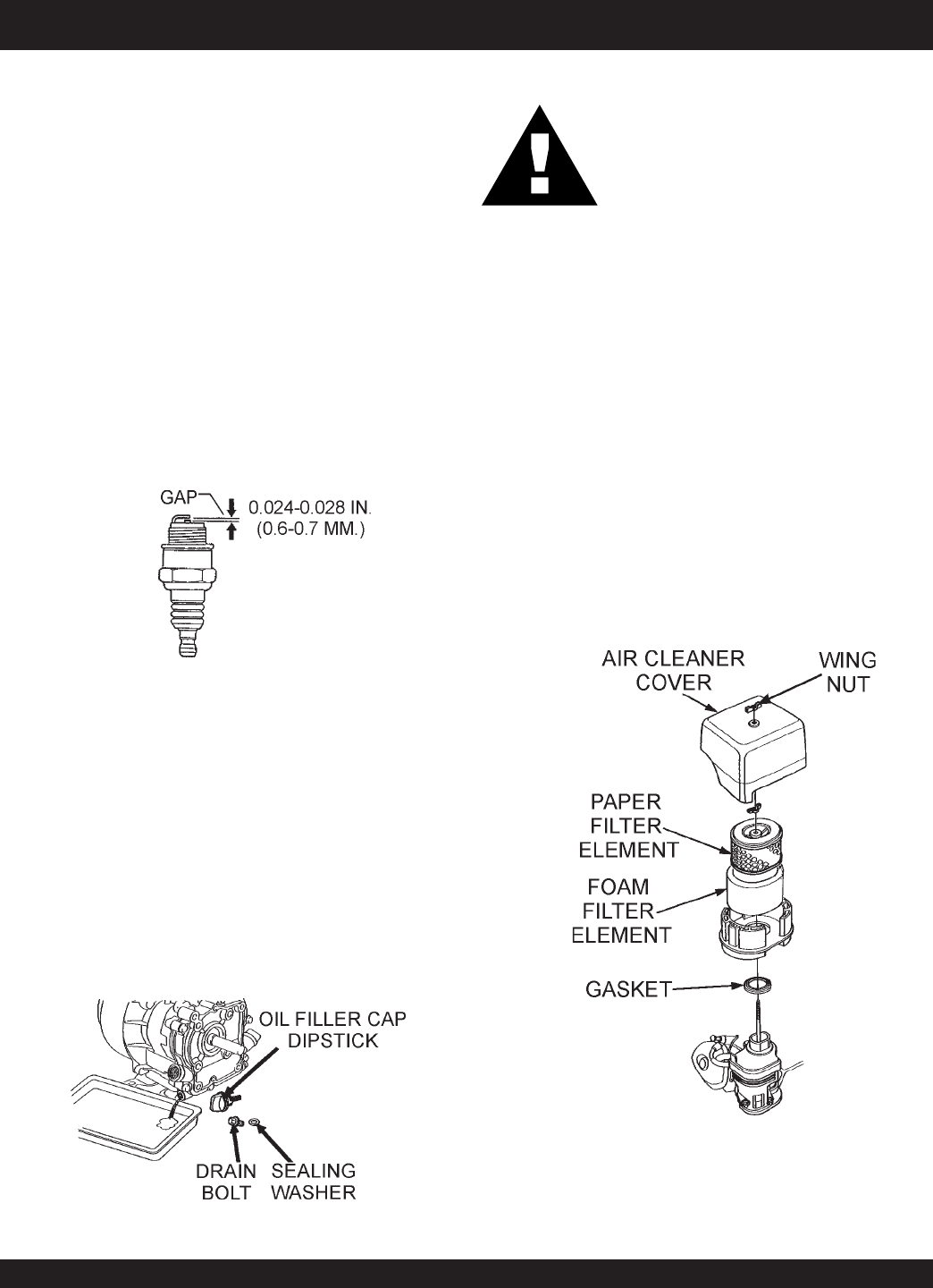
7. Air Cleaner – Prevents dirt and other debris from entering
the fuel system. Remove wing-nut on top of air filter
cannister to gain access to filter element.
8. Spark Plug – Provides spark to the ignition system. Set
spark plug gap to 0.6 - 0.7 mm (0.028 - 0.031 inch). Clean
spark plug once a week.
9. Muffler – Used to reduce noise and emissions.
Engine components can generate extreme heat.
To prevent burns, DO NOT touch these areas
while the engine is running or immediately after operating. NEVER
operate the engine with the muffler removed.
10. Fuel Tank – Holds unleaded gasoline. For additional
information refer to engine owner's manual.
WARNING
WARNING
NOTE
Operating the engine without an air filter,
with a damaged air filter, or a filter in need of
replacement will allow dirt to enter the
engine, causing rapid engine wear.
WARNING
Honda GX Series Engine Shown
STOW CMS-9S CONCRETE MIXER — PARTS & OPERATION MANUAL — REV. #6 (01/08/07) — PAGE 15
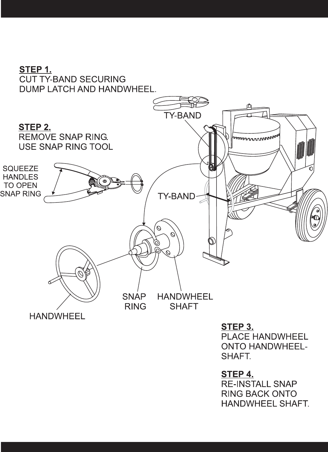
STOW CMS-9S CONCRETE MIXER — HANDWHEEL ASSEMBLY
Assembly
The MC-92P and MC-92S concrete mixers are shipped with
the handwheel detached. Attach the handwheel to the mixer
as shown in Figure 4.
Figure 4. Handwheel Assembly
PAGE 16 — STOW CMS-9S CONCRETE MIXERS — PARTS & OPERATION MANUAL — REV. #6 (01/08/07)
STOW CMS-9S CONCRETE MIXER — TOWING GUIDELINES
To reduce the possibility of an accident while transporting
the mixer on public roads, always make sure that the mixer
towing components and the towing vehicle are in good
operating condition and both units are mechanically sound.
The following list of suggestions should be used when towing
the mixer:
CAUTION:CAUTION:
CAUTION:CAUTION:
CAUTION:
Towing Safety Precautions
■
Check with your county or state safety
towing regulations department before
towing your
mixer
.
■
Make sure that the hitch and coupling of the towing vehicle
are rated equal to, or greater than the trailer "gross vehicle
weight rating" (GVWR).
■
ALWAYS inspect the hitch and coupling for wear. NEVER
tow the mixer with defective hitches, couplings, chains etc.
■
CHECK the tire air pressure on both the towing vehicle and
the trailer. Also check the tire tread wear on both vehicles.
■
ALWAYS make sure the mixer is equipped with a "Safety
Chain".
■
ALWAYS attach trailer's safety chain to the frame of towing
vehicle.
■
ALWAYS make sure that the towing vehicle's directional,
backup, and brake lights are working properly.
■
Remember in most cases the maximum speed unless
otherwise posted for highway towing is 45 MPH, however
before towing your mixer, check your local state, and county
vehicle towing requirements. Recommended off-road towing
is not to exceed 10 MPH or less depending on type of terrain.
■
Place
chocked blocks
underneath wheels to prevent
rolling,
while parked, if disconnected from towing vehicle.
■
Inflate tires to correct pressure, inspect tires for cuts, and
excessive wear. See Table 16 (Tire Wear Troubleshooting).
■
When towing of the mixer is required, place the drum in the
up position (mouth facing upwards).
■
ALWAYS make sure that the fuel valve lever is in the OFF
position (gasoline models only).
CAUTION:CAUTION:
CAUTION:CAUTION:
CAUTION:
If the mixer tow bar is deformed or damaged
replace entire tow bar. NEVER tow the mixer
with a defective tow bar. There exist the
possibility of the trailer separating from the
towing vehicle.
Tow Bar to Vehicle Connection (Coupler Only)
1. Check the vehicle hitch ball, and mixer's coupler for
signs of wear or damage. Replace any parts that are
worn or damaged before towing.
2. Use only a 2-inch ball diameter (towing vehicle), this
will match the mixer's 2-inch coupler. Use of any other
ball diameter will create an extremely dangerous condition
which can result in separation of the coupler and ball or
ball failure.
3. After tow bar has been connected to mixer (see next
page), attach mixer's coupler to the hitch ball on the
towing vehicle securely and make sure the lock lever
is in the down position (locked).
Mixer Tow Bar Vehicle Connection (Pintle and Loop)
1. Make sure the bumper on the towing vehicle is equipped
to handle either a pintle or loop type tow bar configuration.
2. After tow bar has been connected to mixer (see next
page), secure either type of tow bar to the towing vehicle,
following state and county towing regulations.
3. As a minimum, use a 1/2-inch bolt and nylock nut grade
5 when securing either tow bar to the towing vehicle,
■
Check wheel mounting lug nuts with a torque wrench.
Torque wheel lug nuts as described in the maintenance
section of this manual.
■
Check tightness of U-clamp nuts, torque suspension
hardware as referenced in the maintenance section of this
manual.
■
Avoid sudden stops and starts. This can cause skidding, or
jackknifing. Smooth, gradual starts and stops will improve
gas milage.
■
Avoid sharp turns to prevent rolling.
STOW CMS-9S CONCRETE MIXER — PARTS & OPERATION MANUAL — REV. #6 (01/08/07) — PAGE 17
STOW CMS-9S CONCRETE MIXER — SAFETY CHAIN CONNECTION
NEVER ! tow the mixer with the safety chain
removed. The safety chain is intended to
prevent complete separation of the mixer from
the towing vehicle in the event of a tow bar
failure.
CAUTION:CAUTION:
CAUTION:CAUTION:
CAUTION:
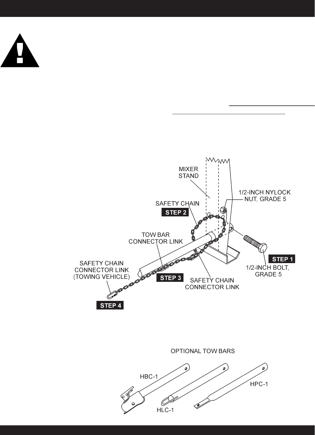
Reference Figure 5 for the installation of the
Saftey Chain
.
Tow Bar to Mixer Connection
1. Insert the tow bar through the round opening at the
bottom of the mixer stand.
Align the hole on the tow bar with the hole on the mixer
frame, and insert 1/2-inch bolt through tow bar and frame.
Secure tow bar to frame with 1/2-inch nylock nut. Tighten
to 40 ft.-lbs.
2. Route the safety chain through the holes just above the
tow bar, located on each side of the mixer stand.
Loop the chain together and place under the tow bar.
Secure the loop with the connector link.
3. Extend the safety chain along the length of the tow bar,
looping it through the tow bar's connector link. Remove
any excess chain slack.
4. Connect the free end of (connector link) the safety chain
to the towing vehicle.
Remember it is critical that the
length of the chain be properly adjusted
, to prevent
the
draw bar
and the front of the mixer stand from
dropping to the the ground (contact) in the event the
draw bar becomes disconnected from the towing vehicle.
Figure 5. Tow Bar and Safety Chain Installation
PAGE 18 — STOW CMS-9S CONCRETE MIXERS — PARTS & OPERATION MANUAL — REV. #6 (01/08/07)
STOW CMS-9S CONCRETE MIXER — ELECTRIC MOTOR
Electric Motor
For maintenance care and operation of the electric motor, refer
to your electric motor instruction booklet furnished with the electric
motor.
Protect the electric motor from dust as much as possible and
keep ventilating openings clean.
The electric motor used in this mixer is a single-phase 1.5 HP
motor. The input voltage requirement for this motor is either 115
or 230 VAC only.
Electric Motor Connection
A 12 inch electrical cable (Figure 2) with a pigtail at one end is
provided with the electrical motor for hookup to a power source.
Table 1. shows the required NEMA connector for the desired
motor horsepower rating. In addition, Table 2 also shows the
matching NEMA approved connector for the required extension
cord.
ALWAYS
, make certain that the power source required for the
electric motor is
correct
and always use the correct NEMA
configuration plug.
Failure
to supply the correct voltage to the
motor can severely damage the motor.
The electric motor supplied with the mixer is configured from the
factory for 115 VAC grounded operation. Make certain that the correct
size grounded (3-wires) extension cord is used. See Table 5.
Motors can burn out when the line voltage falls 10% below the
voltage rating of the motor. Failure to use proper voltage will
cause the motor to overheat and actuate the overload switch.
If overload protection should actuate because of improper voltage
or any other malfunction, turn the main switch on the motor to the
"OFF" position and correct the problem, press the reset switch
button, and turn the main switch to the "ON" position.
CAUTION:
■
DO NOT spray water at any time on the
electric motor
.
■
DO NOT operate electric motor in a
explosive environment.
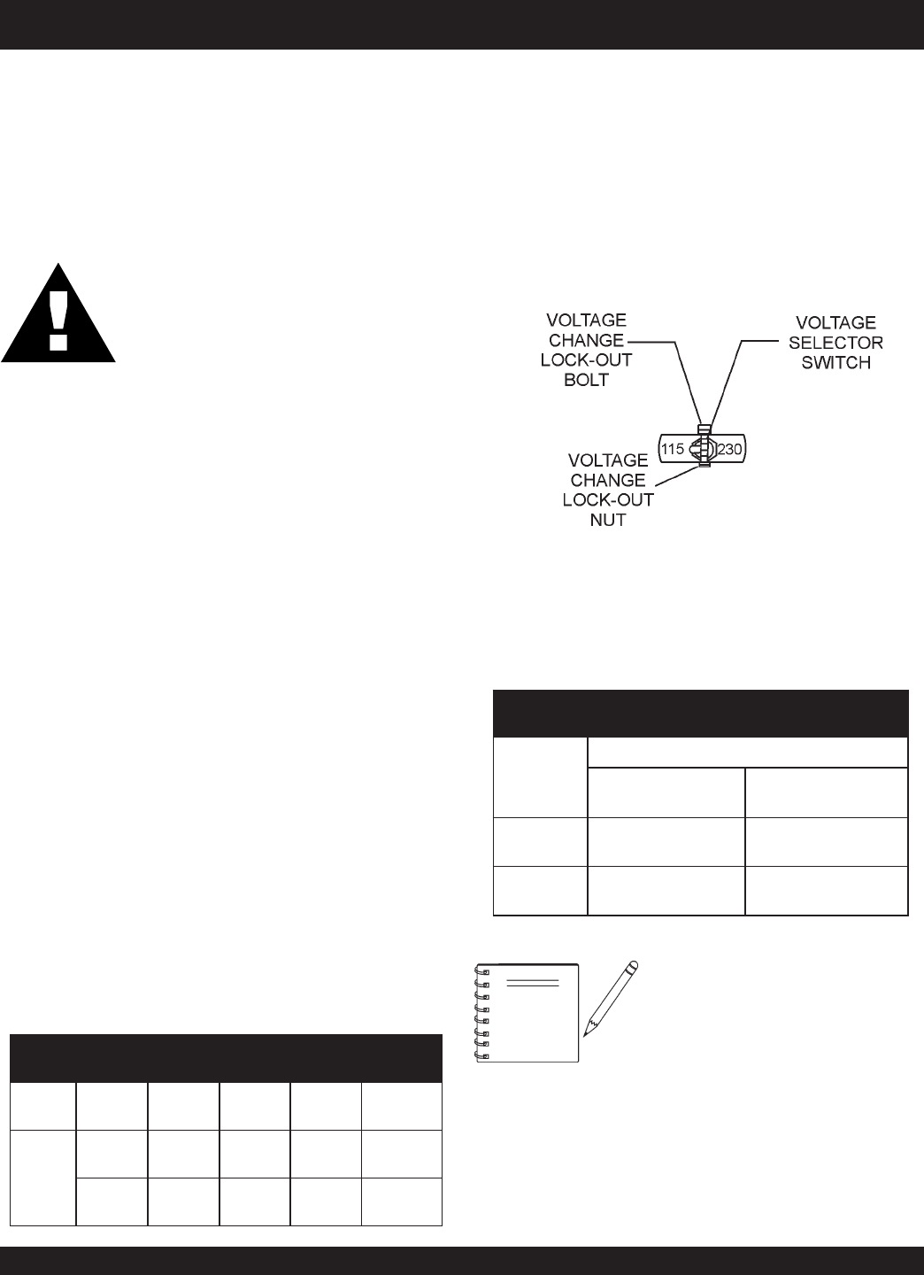
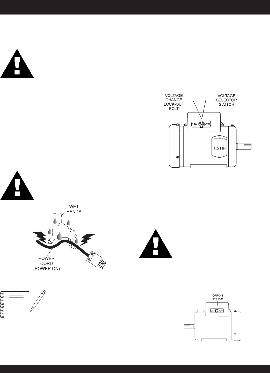
Electric Motor Voltage Change Switch
1.
ALWAYS
make certain the electric motor's ON/OFF switch
is in the "OFF" position and the power cord has been
disconnected from the power source.
2. Remove the voltage change lock-out bolt and nut
(Figure 6).
Change the position of the
voltage change toggle switch
from 115 VAC to 230 VAC. The mixer is factory wired for 115
VAC operation.
3. Re-install the voltage change lock-out bolt and nut.
NOTE
NEVER!
disable or disconnect the
ON/OFF switch on the electric motor.
It is provided for operator safety. Injury
may result if it is disable, disconnected
or improperly maintained.
Figure 6. Voltage Change Switch
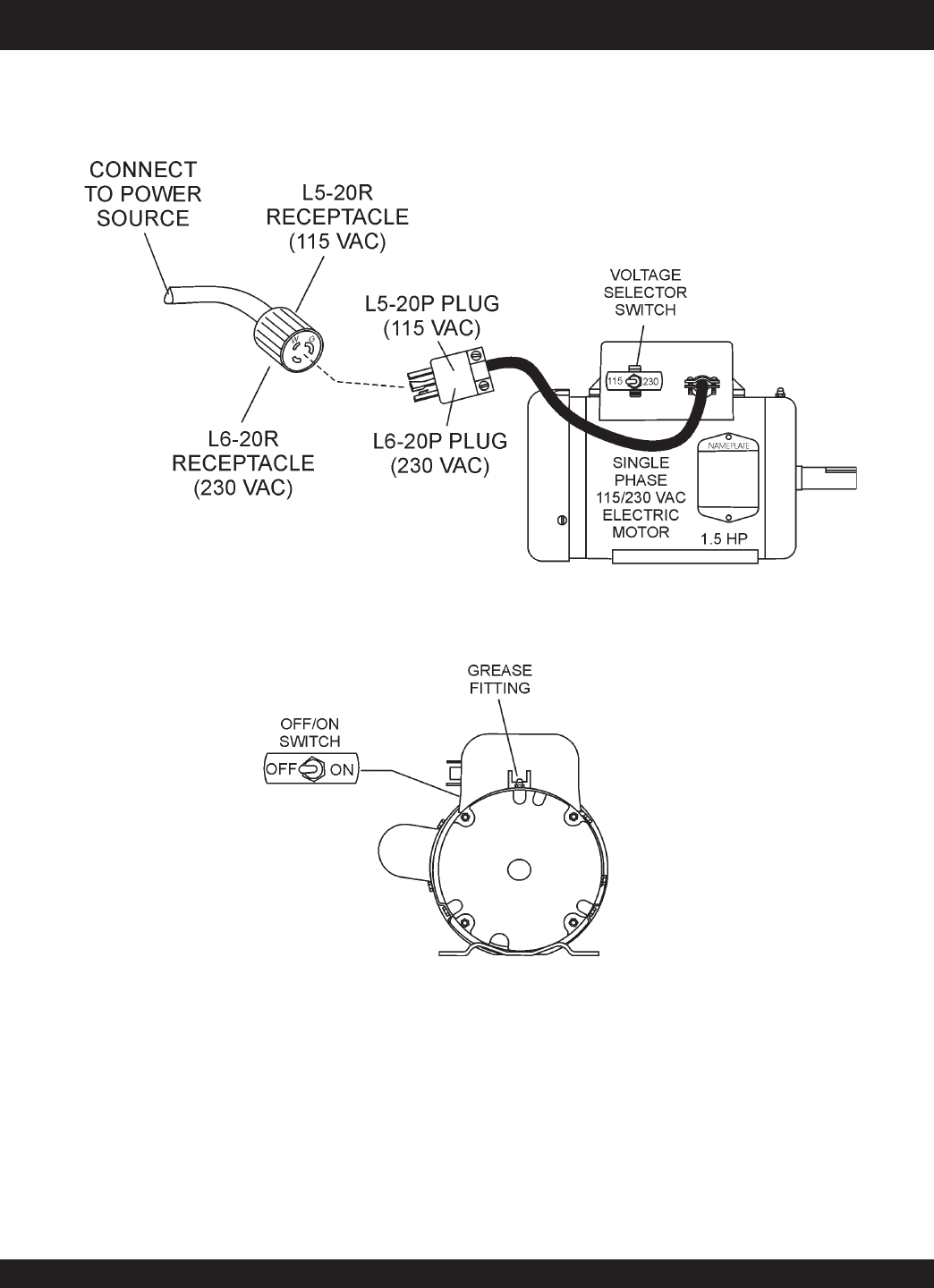
4.
Important!,
when changing the input voltage to the electric
motor from 115 to 230 VAC, the
plug
on the electric motor
power cord must also be changed. See Table 6 and Figure 7.
eziSdroCnoisnetxEdednemmoceR.5elbaT
ss
s
ss
cirtcelE
rotoM
tupnI
egatloV
.tf05
)m42.51(
.tf57
)m68.22(
.tf001
)m84.03(
.tf002
)m69.06(
PH5.1
CAV51121.oN01.oN8.oN6
.oN
CAV03241.oN21.oN21.oN8.oN
noitamrofnIgniriWrotoMcirtcelE.6elbaT
rotoM
rewopesroH
gnitaR
esahPelgniS-CAV032-511
rotcennoCgulPAMENAMENgnitaM
rotcennoCelcatpeceR
PH5.1
)CAV511( 735049MEN/PP02-5L835049MEN/PR02-5L
PH5.1
)CAV032( 935049N/PP02-6L045049N/PR02-6L
STOW CMS-9S CONCRETE MIXER — PARTS & OPERATION MANUAL — REV. #6 (01/08/07) — PAGE 19
Figure 7. Single Phase Electric Motor with 12 inch Pigtail Cable
STOW CMS-9S CONCRETE MIXER — ELECTRIC MOTOR
PAGE 20 — STOW CMS-9S CONCRETE MIXERS — PARTS & OPERATION MANUAL — REV. #6 (01/08/07)
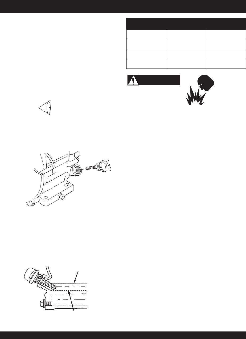
STOW CMS-9S CONCRETE MIXER — PRE-INSPECTION (GAS ENGINE)
Figure 8. Engine Oil Dipstick (Removal)
3. Insert and remove the dipstick without screwing it into the
filler neck. Check the oil level shown on the dipstick.
4. If the engine oil level is low (Figure 9), fill to the edge of
the oil filler hole with the recommended oil type (Table 7).
See Table 2 for the oil capacity of your type engine.
Figure 9. Engine Oil Dipstick (Oil Level)
epyTliO.7elbaT
nosaeS erutarepmeT epyTliO
remmuS rehgiHroC°52 03-W01EAS
llaF/gnirpS C°01~C°52 02/03-W01EAS
retniW rewoLroC°0 01-W01EAS
Fuel Check
If your mixer has a gasoline engine, determine if the engine fuel
is low. If fuel is low, remove the fuel filler cap and fill with
unleaded
gasoline. Motor fuels are highly flammable and can be dangerous
if mishandled. DO NOT smoke while refueling. DO NOT attempt
to refuel the trowel if the engine is
hot!
or
running
.
1. Remove the gasoline cap located on top of fuel tank.
2. Visually inspect to see if fuel level is low. If fuel is low, replenish
with unleaded fuel.
3. When refueling, be sure to use a strainer for filtration. DO
NOT top-off fuel. Wipe up any spilled fuel.
V-belt Check
A worn or damaged V-belt can adversely affect the performance
of the mixer. If a V-belt is defective or worn simply replace the V-
belt as outlined in the maintenance section of this manual.
Blade Check
Check for worn blades. If using a steel tub and the blades are
worn, replace the entire tub assembly. Remember the blades
are welded to tub.
If using a plastic tub, replace the blades using the part numbers
referenced in the parts section of this manual.
Start/Stop Switches
This mixer has been equipped with a start/stop switches for both
the gasoline and electric motor mixers. These switches should be
tested every time the engine or motor is started.
Grease Fittings (Zerk)
Check the zerk grease fittings (Figure 27) as shown in the
maintenance section of this manual. These grease fittings lubricate
the
handwheel
and the
yoke mechanism
.
Explosive Fuel
Before Starting
1. Read safety instructions at the beginning of manual.
2. Clean the
mixer
, removing dirt and dust, particularly the
engine cooling air inlet, carburetor and air cleaner.
3. Check the air filter for dirt and dust. If air filter is dirty, replace
air filter with a new one as required.
4. Check carburetor for external dirt and dust. Clean with dry
compressed air.
5. Check fastening nuts and bolts for tightness.
Engine Oil Check
1. To check the engine oil level, place the mixer on
secure level ground with the engine stopped.
2. Remove the filler dipstick from the engine oil filler hole
(Figure 8) and wipe it clean.
STOW CMS-9S CONCRETE MIXER — PARTS & OPERATION MANUAL — REV. #6 (01/08/07) — PAGE 21
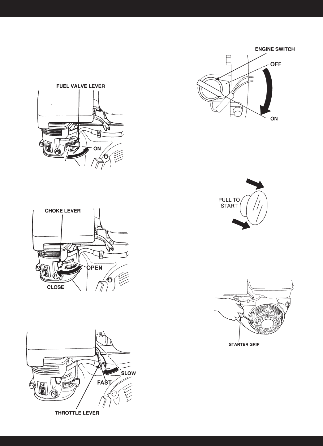
STOW CMS-9S CONCRETE MIXER — INITIAL START-UP (GAS ENGINE)
Starting the Engine (Gasoline Only)
The following steps outline the procedure for starting the engine.
Depending on the type of engine employed in the mixer the
steps may vary slightly. If your mixer has an electric motor
disregard this section.
1. Move the fuel shut-off lever (Figure 10) to the ON position.
Figure 10. Fuel Shut-OFF Lever
2. To start a cold engine, move the choke lever (Figure 11) to
the CLOSED position.
Figure 11. Choke Lever
3. Move the throttle lever (Figure 12) away from the slow
position, about 1/3 of the way toward the fast position.
Figure 12. Throttle Lever
4. Turn the engine switch (Figure 13) to the ON position.
Figure 13. Engine ON/OFF Switch
5. Located at the rear of the mixer frame is the main
start/
stop
button (Figure 14). Pull this button outward to start the
engine.
Figure 14. Engine Start/Stop Button
Figure 15. Starter Grip
6. Pull the
starter grip
(Figure 15) lightly until you feel
resistance, then pull briskly. The drum should be rotating at
this time.
PAGE 22 — STOW CMS-9S CONCRETE MIXERS — PARTS & OPERATION MANUAL — REV. #6 (01/08/07)
CAUTION:CAUTION:
CAUTION:CAUTION:
CAUTION:
DO NOT attempt to operate the mixer until
the Safety, General Information and
Inspection sections have been read and
understood.
Initial Start-up Instructions (Electric Motor)
Starting
1. Before starting, make sure mixer is positioned on a secure
flat surface to prevent rolling.
2. Use an extension cord (see Table 5) of adequate current
carrying capacity, insert the electric motor's power plug into
one end of the extension cord.
3.
NEVER!
use a
worn
or
frayed
extension cord.
4.
NEVER!
operate mixer with V-belt cover removed.
6. Plug the other end of the extension cord into either a 115 or
230 VAC power source (look at position of voltage selector
switch). Remember to read the nameplate to determine the
motor's input voltage requirement.
DANGERDANGER
DANGERDANGER
DANGER
NEVER!
touch the power cord (Figure 16)
with
wet hands
or while
standing in water
when it is connected to a power source. The
possibly exists of electrical shock
(electrocution) even death.
NEVER!
spray
water directly on the electric motor.
Figure 16. Extension Cord (Wet Hands)
WARNING:WARNING:
WARNING:WARNING:
WARNING:
ALWAYS read the label on the electric motor
before applying power. The label will indicate
the correct power requirements for the motor.
Remember the use of an incorrect input
voltage will severely damage the electric
motor.
To prevent personnel from tripping over
the extension cord, position the
extension cord so that it lays flat and is
not curled underneath the mixer.
STOW CMS-9S CONCRETE MIXER — INITIAL START-UP (ELECT. MOTOR)
Starting the Electric Motor
1. Set the electric motor's ON/OFF switch (Figure 18) to the
ON position.
5. Place the voltage selector switch (Figure 17) in the position
that is in accordance with voltage listed on the electric motor's
nameplate. The electric motor's are shipped from the factory
with the with the voltage selector switch placed in the 115 VAC
position.
If 230 VAC is required, remove the locking bolt and nut and
flip the voltage selector toggle switch to the 230 VAC
position. Reinstall the locking bolt and nut to prevent the
toggle switch from being accidently tripped.
NOTE
Figure 17. Voltage Change Switch
(115 VAC Position)
Figure 18. Electric Motor ON/OFF Switch
(ON Position)
STOW CMS-9S CONCRETE MIXER — PARTS & OPERATION MANUAL — REV. #6 (01/08/07) — PAGE 23
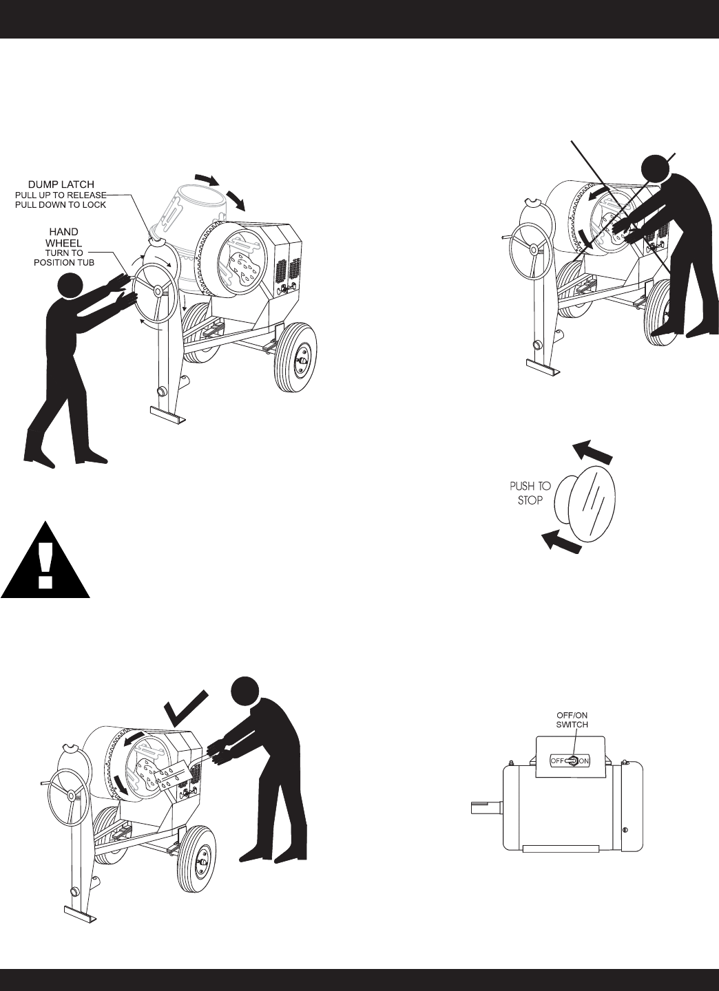
2. As the drum rotates, use a shovel (Figure 20) to place the
cement mix inside the drum, add water as required. Be careful
to only place the
tip
of the shovel inside the drum.
Figure 19. Mixing Drum Positioning
3. Placing the shovel all the way inside the drum (Figure 21) will
cause the shovel to strike the blades. This condition will make
the shovel rotate, and could cause injury to personnel.
NEVER place hands inside the mixing drum while it is
rotating.
Operation
1. To position the tub, make sure the mixer is placed on firm
level
ground,
then
pull up
on the
dump latch
(Figure 19) and turn
the
hand wheel
until the tub is at the desired position. Once
the tub is at the desired position,
pull down
on the dump latch
to lock the tub in position.
STOW CMS-9S CONCRETE MIXER — OPERATION
Stopping the Mixer (Gasoline)
1. Push the main
start/stop
switch (Figure 22) inward to stop
the engine.
Stopping the Mixer (Electric)
1. Place the electric motor's
ON/OFF
switch (Figure 23) in
the OFF position.
2. Disconnect the electric motor's extension cord from its
power source.
3. Clean drum of all debris and foreign matter.
2. Place fuel shut-off lever in the OFF position.
3. Clean drum of all debris and foreign matter.
Figure 20. Filling Mixing Drum
Figure 21. Filling Mixing Drum
Figure 22. Start/Stop Button (Stop Position)
Figure 23. Electric Motor ON/OFF Switch
(OFF Position)
CAUTION:CAUTION:
CAUTION:CAUTION:
CAUTION:
NEVER stand in front or behind the mixing
drum while it is being placed in the dump
position. Stay clear of the mixing drum while
it is being positioned.

PAGE 24 — STOW CMS-9S CONCRETE MIXERS — PARTS & OPERATION MANUAL — REV. #6 (01/08/07)
STOW CMS-9S CONCRETE MIXER — MAINTENANCE (ENGINE)
Use Table 8 as a general maintenance guideline when servicing
your engine. For more detail engine maintenance information,
refer to the engine owner's manual supplied with your engine.
eludehcSecnanetniaMenignE.8elbaT
)3(NOITPIRCSEDNOITAREPOEROFEB
TSRIF
HTNOM
RO
.SRH01
YREVE
SHTNOM3
RO
.SRH52
YREVE
SHTNOM6
RO
.SRH05
YREVE
RAEY
RO
.SRH0
01
YREVE
SRAEY2
RO
.SRH002
liOenignE
KCEHCX
EGNAHCX
renaelCriA
KCEHCX
EGNAHC)1(X
stloB&stuNllA fInethgit-eR
yrasseceN X
gulPkrapS
NAELC-KCEHCX
ECALPER X
sniFgnilooCKCEHCX
retserrAkrapSNAELC X
knaTleuFNAELC X
retliFleuFKCEHC X
deepSeldITSUJ
DA-KCEHC )2(X
ecnaraelCevlaVTSUJDA-KCEHC )2(X
senilleuFKCEHC )2()yrassecenfiecalper(sraey2yrevE
nidesunehwylt
neuqerferomecivreS)1( YTSUD .saera
yllacinahcemeradnaslootreporpehtevahuoysselnu,relaedecivresruoyybdeci
vresebdluohssmetiesehT)2(
.serudecorpecivresroflaunaMpohSNIBORroADNOHehtotrefeR.tneiciforp
.slavretniec
nanetniamreporpenimretedotnoitarepofosruohgol,esulaicremmocroF)3(
STOW CMS-9S CONCRETE MIXER — PARTS & OPERATION MANUAL — REV. #6 (01/08/07) — PAGE 25
Maintenance
Perform the scheduled maintenance procedures as defined by
Table 6 and below:
DAILY
■
Thoroughly remove dirt and oil from the engine and control
area. Clean or replace the air cleaner elements as necessary.
Check and retighten all fasteners as necessary. Check the
gearbox for oil leaks. Repair or replace as needed.
WEEKLY
■
Remove the fuel filter cap and clean the inside of the fuel
tank.
■
Remove or clean the filter at the bottom of the tank.
■
Remove and clean the spark plug (Figure 24), then adjust
the spark gap to 0.024 ~0.028 inch (0.6~0.7 mm). This unit
has electronic ignition, which requires no adjustments.
DO NOT use gasoline as a cleaning solvent,
because that would create a risk of fire or
explosion.
DANGER :
ENGINE OIL
1. Drain the engine oil when the oil is
warm
as shown in
Figure 25.
2. Remove the oil drain bolt and sealing washer and allow
the oil to drain into a suitable container.
3. Replace engine oil with recommended type oil as listed
in Table 7. For engine oil capacity, see Table 2 (engine
specifications). DO NOT overfill.
4. Install drain bolt with sealing washer and tighten se-
curely.
Figure 25. Engine Oil (Draining)
Figure 24. Spark Plug Gap
STOW CMS-9S CONCRETE MIXER — MAINTENANCE (ENGINE)
ENGINE AIR CLEANER
1. Remove the air cleaner cover and foam filter element as
shown in Figure 26.
2. Tap the paper filter element (Figure 34) several times on a
hard surface to remove dirt, or blow compressed air [not
exceeding 30 psi (207 kPa, 2.1 kgf/cm2)] through the filter
element from the air cleaner case side.
NEVER
brush off dirt.
Brushing will force dirt into the fibers. Replace the paper filter
element if it is excessively dirty.
3. Clean foam element in warm, soapy water or nonflammable
solvent. Rinse and dry thoroughly. Dip the element in clean
engine oil and completely squeeze out the excess oil from the
element before installing.
Figure 26. Engine Air Cleaner
PAGE 26 — STOW CMS-9S CONCRETE MIXERS — PARTS & OPERATION MANUAL — REV. #6 (01/08/07)
Ball Socket and Clamp Face Maintenance
1. If the towing vechicle is equipped with a ball socket, smear
socket periodically with multi-purpose grease.
This will keep
the ball socket well lubricated.
2. Periodically oil
pivot points
and
clamp face
surfaces of
coupler with SAE 30 WT. motor oil.
3. When parking or storing your mixer. Keep the coupler off
the ground so dirt will not build up in the ball socket.
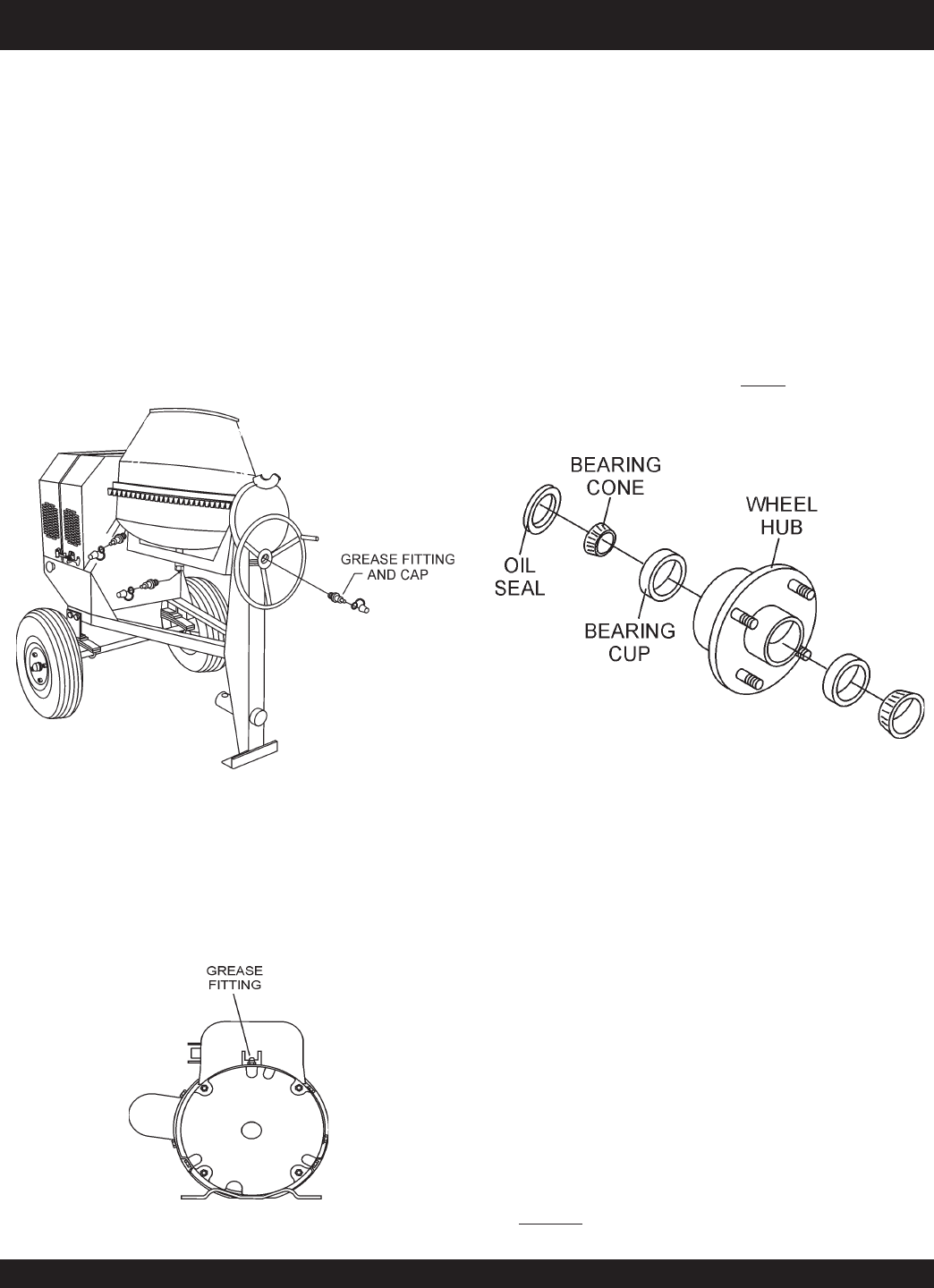
Grease Fittings (Zerk) Maintenance (Mixer)
There are 3 grease (Figure 27) fittings that will require
lubrication. Lubricate these fittings
once a week
. Use lithium
base grease, grade N0.1.
Figure 27. Grease Fittings Mixer
STOW CMS-9S CONCRETE MIXER — MAINTENANCE (MIXER)
Wheel Bearings
1. After every 3 months of operation, remove the hub dust cap
and inspect the wheel bearings (Figure 29). Once a year,
or when required, disassemble the wheel hubs remove
the old grease and repack the bearings forcing grease
between rollers, cone and cage with a good grade of high
speed wheel bearing grease (
never
use grease heavier
than 265 A.S.T.M. penetration (“No. 2.”)
Figure 29. Wheel Hub and Bearings
2. Fill the wheel hub (Figure 29) with grease to the inside
diameter of the outer races and also fill the hub grease cap.
Reassemble the hub and mount the wheel. Then tighten
the adjusting nut, at the same time turn the wheel in both
directions, until there is a slight bind to be sure all the
bearing surfaces are in contact.
Then back-off the adjusting nut 1/6 to 1/4 turn or to the
nearest locking hole or sufficiently to allow the wheel to
rotate freely within limits of .001" to .010" end play. Lock the
nut at this position. Install the cotter pin and dust cap, and
tighten all hardware.
Mixer Cleaning
1. For thorough mix and longer drum life,
always
wash drum
out after each use.
2.
NEVER!
pour or spray water over the engine or electric
motor.
Grease Fittings (Zerk) Maintenance (Electric Motor)
1. There are two grease (Figure 28) fittings at each end of the
electric motor that will require lubrication. Lubricate these
fittings
about
every 16 months.
Figure 28. Grease Fittings Electric Motor
2. Use Poleyrex EM (Exxon Mobil) or equalivant lubricant.
Clean grease fitting, apply grease gun to fitting (1/2 shot).
Remember too much grease or injecting grease too quickly
can cause premature bearing failure. Slowly apply the
recommended amount of grease, taking a miniute or so to
apply.
STOW CMS-9S CONCRETE MIXER — PARTS & OPERATION MANUAL — REV. #6 (01/08/07) — PAGE 27
STOW CMS-9S CONCRETE MIXER — MAINTENANCE (MIXER)
Tires/Wheels/Lug Nuts
Tires and wheels are a very important and critical compo-
nents of the trailer. When specifying or replacing the trailer
wheels it is important the wheels, tires, and axle are prop-
erly matched.
DO NOT attempt to repair or modify a
wheel. DO NOT install an inter-tube to
correct a leak
through the rim.
If the rim is cracked, the air
pressure in the inter-tube may
cause pieces of the rim to explode
(break-off) with great force and
can cause serious eye or bodily
injury.
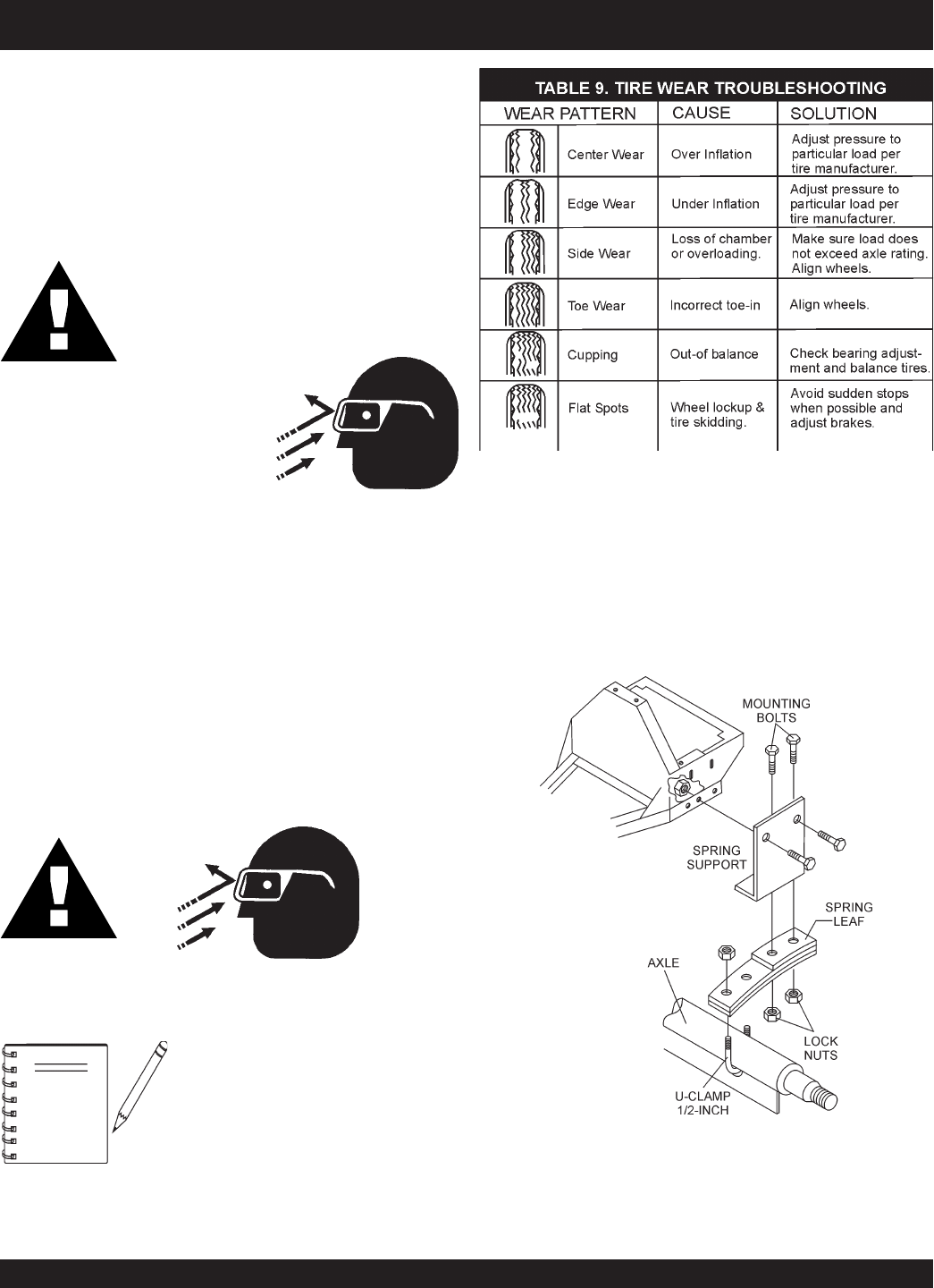
Tires Wear/Inflation
Tire inflation pressure is the most important factor in tire
life. Pressure should be checked cold before operation. DO
NOT bleed air from tires when they are hot. Check inflation
pressure weekly during use to insure the maximum tire life
and tread wear.
Table 9 (Tire Wear Troubleshooting) will help pinpoint the
causes and solutions of tire wear problems.
ALWAYS
wear safety glasses
when removing or installing force
fitted parts. Failure to comply may
result in serious injury.
Figure 30. Suspension Components
Suspension
The leaf suspension springs and associated components
(Figure 30) should be visually inspected every 6,000 miles
for signs of excessive wear, elongation of bolt holes, and
loosening of fasteners. Replace all damaged parts (sus-
pension) immediately. Torque locknut securing U-clamp to
spring leaf between 45 and 50 ft.-lbs.
CAUTION:
NOTE
CAUTION:CAUTION:
CAUTION:CAUTION:
CAUTION:
PAGE 28 — STOW CMS-9S CONCRETE MIXERS — PARTS & OPERATION MANUAL — REV. #6 (01/08/07)
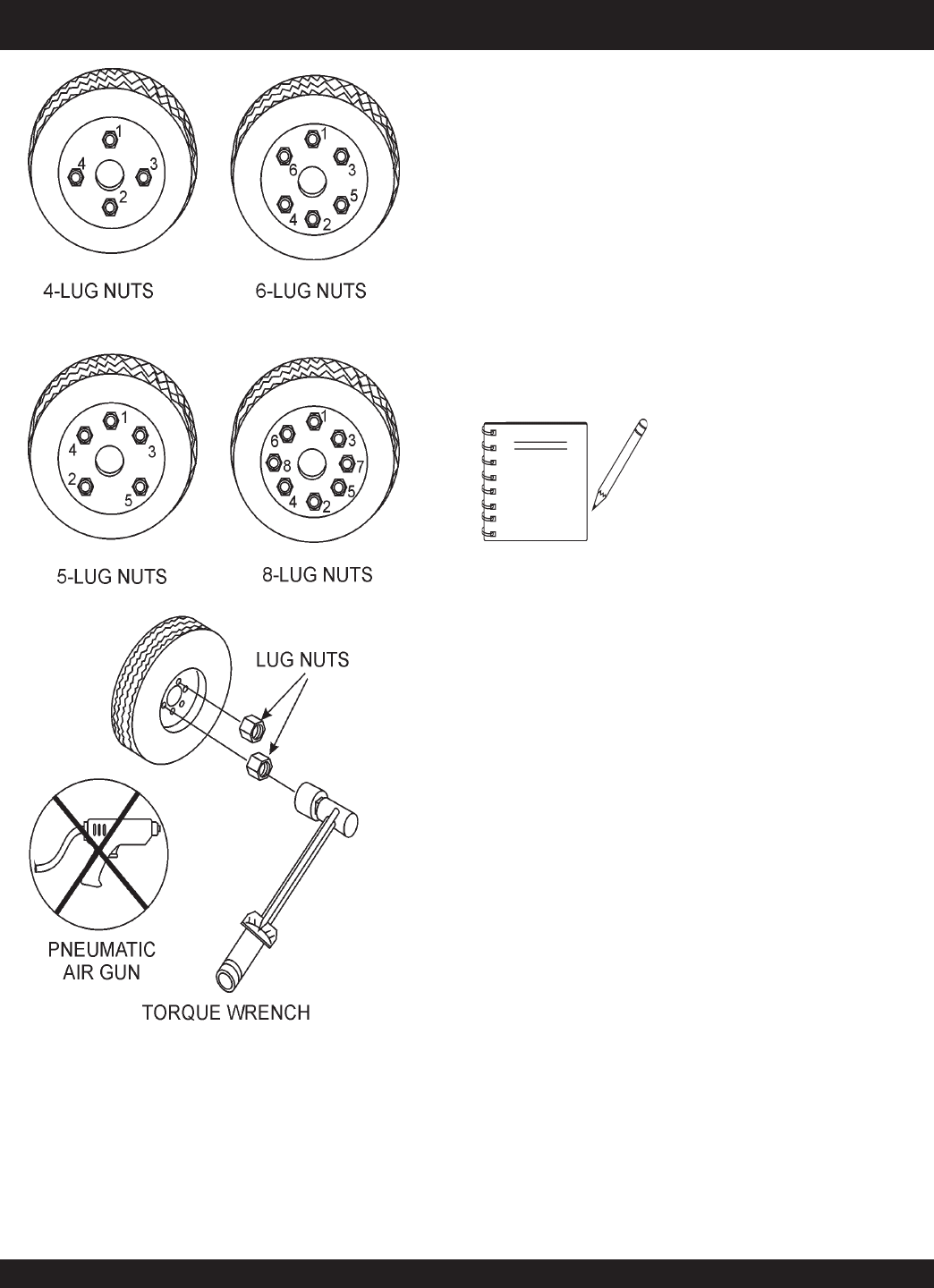
Lug Nut Torque Requirements
It is extremely important to apply and maintain proper wheel
mounting torque on the trailer. Be sure to use only the fas-
teners matched to the cone angle of the wheel. Proper pro-
cedure for attachment of the wheels is as follows:
1. Start all wheel lug nuts by hand.
2. Torque all lug nuts in sequence. See Figure 31. DO NOT
torque the wheel lug nuts all the way down. Tighten each lug
nut in 3 separate passes as defined by Table 10.
3. After first road use, retorque all lug nuts in sequence. Check
all wheel lug nuts periodically.
NEVER!
use an pneumatic air gun
to tighten wheel lug nuts.
Figure 31. Wheel Lug Nuts Tightening Sequence
NOTE
Mixer Storage
For storage of the mixer for over 30 days, the following is
recommended:
z
Drain the fuel tank completely, or add STA-BIL to the
fuel.
z
Run the engine until the fuel is completely consumed.
z
Completely drain used oil from the engine crankcase
and fill with fresh clean oil, then follow the procedures
described in the engine manual for engine storage.
z
Clean the entire mixer and engine compartment.
z
Place the mixing drum in the down position (mouth facing
downward).
z
Cover the mixer and place it a clean dry area, that is
protected from harsh elements.
STOW CMS-9S CONCRETE MIXER — MAINTENANCE (MIXER)

STOW CMS-9S CONCRETE MIXER — PARTS & OPERATION MANUAL — REV. #6 (01/08/07) — PAGE 29
NOTE PAGE
PAGE 30 — STOW CMS-9S CONCRETE MIXERS — PARTS & OPERATION MANUAL — REV. #6 (01/08/07)
STOW CMS-9S CONCRETE MIXER — TROUBLESHOOTING (ENGINE)
Practically all breakdowns can be prevented by proper
handling and maintenance inspections, but in the event of a
breakdown, please take a remedial action following the
diagnosis based on the Troubleshooting (Tables 10 and 11)
information shown below and on the next page. If the problem
cannot be remedied, please leave the unit just as it is and
consult our company's business office or service plant.
GNITOOHSELBUORTENIGNE.01ELBAT
MOTPMYS MELBORPELBISSOP NOITULOS
tratsottluciffiD
gulpkrapstubelbaliavasileuF
elbaliavarewoP(.etingitonlliw
.)elbacnoisnethgihta
?egdirbgniebgulpnoitingI .metsysnoitingikcehC
?noitingitatisopednobraC .noitingiecalperronaelC
evitcefedoteudtiucrictrohS
?srotalusni
.srotalusniecalpeR
?pagkrapsreporpmI .pagtcerrocehtotpaggulpkrapsteS
gulpkrapstubelbaliavasileuF
rewoP(.etingitonlliw TON
.)elbacnoisnethgihtaelbaliava
?hctiwspotstatiucrictrohS .evitcefedfihctiwspotsecalpeR.tiucrichctiwspotskcehC
?evitcefedliocnoitingI .liocnoitingiecalpeR
gulpkrapsdnaelbaliavasileuF
noisserpmoc(setingi )lamron .
nobrachtiwdeggolcrelffuM
?stisoped
.relffumecalperronaelC
,retaw(etauqedaniesunileuF
?)tsud
.leufhserfhtiwecalperdnametysleufhsulF
?deggolcrenaelCriA .renaelcriaecalperronaelC
gulpkrapsdnaelbaliavasileuF
noisserpmoc(setingi wol .)
?teksagdaehrednilycevitcefeD .teksagdaehecalperrostlobdaehrednilycnethgiT
?nrowrednilyC .rednilycecalpeR
?esoolgulpkrapS .gulpkrapsnehgiT
yrotcafsitastonnoitarepO
elbaliavarewophguonetoN
-ssimon,lamronnoisserpmoc(
.)gnirif
?deggolcrenaelcriA
?enilleufniriA .enilleufmorf)riaevomer(deelB
taolfrotaerubracnilevelleuF
?reporpmirebmahc taolfrotaerubractsujdA
?rednilycnistisopednobraC rednilycecalperronaelC
elbaliavarewophguonetoN
-ssim,lamronnoisserpmoc(
.)gnirif
?evitcefedliocnoitingI .leufhserfhtiwecalperdnametysleufhsulF
?strohsnetfogulpnoitingI .noitinginaelc,seriwnoitingiecalpeR
,retaw(etauqedaniesunileuF
?)tsud
.leufhserfhtiwecalperdnametysleufhsulF
.staehrevoenignE
ninoitsopednobracevissecxE
?rebmahcnoitsubmoc
.esacknarcecalperronaelC
htiwdeggolcrelffumrotsuahxE
.nobrac
.relffumecalperronaelC
?tcerrocnieulavtaehgulpkrapS .gulpkrapsepyttcerrochtiwgulpkrapsecalpeR

STOW CMS-9S CONCRETE MIXER — PARTS & OPERATION MANUAL — REV. #6 (01/08/07) — PAGE 31
STOW CMS-9S CONCRETE MIXER — TROUBLESHOOTING (ENG./MIXER)
)deunitnoC(GNITOOHSELBUORTENIGNE.01ELBAT
MOTPMYS MELBORPELBISSOP NOITULOS
yrotcafsitastonnoitarepO
.setautculfdeepslanoitatoR
?reporpmitnemtsujdaronrevoG .reveltcerrocotronrevogtsujdA
?evitcefedgnirpsronrevoG .noitingiecalperronaelC
?citarrewolfleuF .enilleufkcehC
noitcushguorhtninekatriA
?enil
.enilnoitcuskcehC
gnikrowtonretratslioceR
.ylreporp
?trapgnitatornitsuD .ylbmessaretratsliocernaelC
?eruliafgnirpsgnirpS .gnirpslairpsecalpeR
GNITOOHSELBUORTREXIM.11ELBAT
MOTPMYS MELBORPELBISSOP NOITULOS
.hguorsetatormurD
?raeggnirevitcefeD saecalpeR.nrowtonerasgniraebdnaraeggnirehttahtkcehC
.yrassecen
?raegnoinipevitcefeD saecalpeR.nrowtonerasgniraebdnaraegnoinipehttahtkcehC
.yrassecen
?tleb-VnroW .tleb-VecalpeR
?yellupesooL .yellupecalperronethgiT
.llataetatortonseodmurD
gniebegatlovonrotcerrocnI
?rotomcirtceleotdeilppus .egatlovylppustcerrocehtsahrotomcirtceleehttahtkcehC
?rotomcirtceleotrewoP nonottubteserhsuP.drocnoisnetxednaecruosrewoptcepsnI
.rotomotdeilppusgniebsiegatlovtcerrocerusekaM.rot
omcirtcele
?leuF
erusekaM.yrassecenfileufddA.knatleufnileuffolevelkcehC
leufehttahterusneotkcehC.enigneehtotdeilppusgniebsileuf
.deggolctonsiretlif
?tleb-VnekorB .tleb-VecalpeR
?sraegnoiniprognirevitcefeD saecalpeR.nekorbtonerasgniraebdnasraegehttahtkcehC
.yrassecen
?rotomcirtceleevitcefeD .rotomcirtceleecalpeR
PAGE 32 — STOW CMS-9S CONCRETE MIXERS — PARTS & OPERATION MANUAL — REV. #6 (01/08/07)
EXPLANATION OF CODE IN REMARKS COLUMN
The contents and part numbers listed in the parts section are
subject to change
without notice
. Multiquip does not
guarantee the availibility of the parts listed.
NOTE
When ordering a part that has more
than one item number listed, check
the remarks column for help in
determining the proper part to order.
QTY. Column
Numbers Used - Item quantity can be indicated by a number,
a blank entry, or A/R.
A/R (As Required) is generally used for hoses or other parts
that are sold in bulk and cut to length.
A blank entry generally indicates that the item is not sold
separately. Other entries will be clarified in the “Remarks”
Column.
REMARKS Column
Some of the most common notes found in the “Remarks”
Column are listed below. Other additional notes needed to
describe the item can also be shown.
Assembly/Kit
- All items on the parts list with the same unique
symbol will be included when this item is purchased.
Indicated by:
“INCLUDES ITEMS W/(unique symbol)”
Serial Number Break
- Used to list an effective serial number
range where a particular part is used.
Indicated by:
“S/N XXXXX AND BELOW”
“S/N XXXX AND ABOVE”
“S/N XXXX TO S/N XXX”
Specific Model Number Use
- Indicates that the part is used
only with the specific model number or model number variant
listed. It can also be used to show a part is NOT used on a
specific model or model number variant.
Indicated by:
“XXXXX ONLY”
“NOT USED ON XXXX”
“Make/Obtain Locally”
- Indicates that the part can be
purchased at any hardware shop or made out of available
items. Examples include battery cables, shims, and certain
washers and nuts.
“Not Sold Separately”
- Indicates that an item cannot be
purchased as a separate item and is either part of an
assembly/kit that can be purchased, or is not available for
sale through Multiquip.
The following section explains the different symbols and remarks
used in the Parts section of this manual. Use the help numbers
found on the back page of the manual if there are any questions.
NO. Column
Unique Symbols - All items with same unique symbol
(*, #, +, %, or >) in the number column belong to the same
assembly or kit, which is indicated by a note in the “Remarks”
column.
Duplicate Item Numbers - Duplicate numbers indicate
multiple part numbers are in effect for the same general item,
such as different size saw blade guards in use or a part that
has been updated on newer versions of the same machine.
PART NO. Column
Numbers Used - Part numbers can be indicated by a number,
a blank entry, or TBD.
TBD (To Be Determined) is generally used to show a part that
has not been assigned a formal part number at time of
publication.
A blank entry generally indicates that the item is not sold
separately or is not sold by Multiquip. Other entries will be
clarified in the “Remarks” Column.
Sample Parts List:
NO. PART NO. PART NAME QTY.REMARKS
1 12345 BOLT ....................... 1 .... INCLUDES ITEMS W/*
2*WASHER, 1/4 IN. ...........
NOT SOLD SEPARATELY
2*12347 WASHER, 3/8 IN. .... 1 ....
MQ-45T ONLY
3 12348 HOSE .................... A/R .. MAKE LOCALLY
4 12349 BEARING ................ 1.... S/N 2345B AND ABOVE

STOW CMS-9S CONCRETE MIXER — PARTS & OPERATION MANUAL — REV. #6 (01/08/07) — PAGE 33
STOW CMS-9S CONCRETE MIXER — SUGGESTED SPARE PARTS
STOW CMS-9S CONCRETE MIXER 1 TO 4 UNITS WITH
HONDA GX240K1HA2 AND ROBIN EH25-2YR000
Qty.P/N Description
2 ....... 503859 ................ V-BELT w/GAS ENGINE, HONDA
2 ....... EM900267 ........... V-BELT w/ELECTRIC MOTOR
1 ....... EM940734 ........... STOP BUTTON w/GAS ENGINE
2 ....... 491010 ................ LATCH SET
1 ....... 505390 ................ EXPANSION PLUG
2 ....... EM903026 ........... SPINDLE BEARING CUP
2 ....... EM903063 ........... SPINDLE BEARING CONES
1 ....... EM505472 ........... SPACER, DRUM (STEEL BARREL)
2 ....... 492179 ................ BEARING JACKSHAFT
2 ....... EM914288 ........... SEAL, AXLE
2 ....... EM903012 ........... BEARING CUP
2 ....... EM903049 ........... BEARING CONE, 7/16" SPINDLE
2 ....... EM903113 ........... BEARING CONE, 1-1/16" SPINDLE
2 ....... 3469 .................... DUST CAP, AXLE
4 ....... 17210ZE2515 ...... ELEMENT, AIR, HONDA
4 ....... 9807956846 ......... SPARK PLUG, HONDA
1 ....... 17620ZH7023 ...... CAP, FUEL TANK, HONDA
1 ....... 28462ZE2W11 ..... ROPE, RECOIL, HONDA
1 ....... 2705011008 ......... RECOIL ROPE, ROBIN
4 ....... 0650140150 ......... SPARK PLUG, ROBIN
1 ....... 0430430015 ......... CAP, FUEL TANK, ROBIN
4 ....... 2703261008 ......... ELEMENT, AIR, ROBIN
NOTE
Part numbers on this Suggested
Spare Parts List may supercede/
replace the P/N's shown in the
test pages of this manual.
PAGE 34 — STOW CMS-9S CONCRETE MIXERS — PARTS & OPERATION MANUAL — REV. #6 (01/08/07)
STOW CMS-9S CONCRETE MIXER — NAME PLATE AND DECALS
NAME PLATE AND DECALS

STOW CMS-9S CONCRETE MIXER — PARTS & OPERATION MANUAL — REV. #6 (01/08/07) — PAGE 35
STOW CMS-9S CONCRETE MIXER— NAME PLATE AND DECALS
NAME PLATE AND DECALS
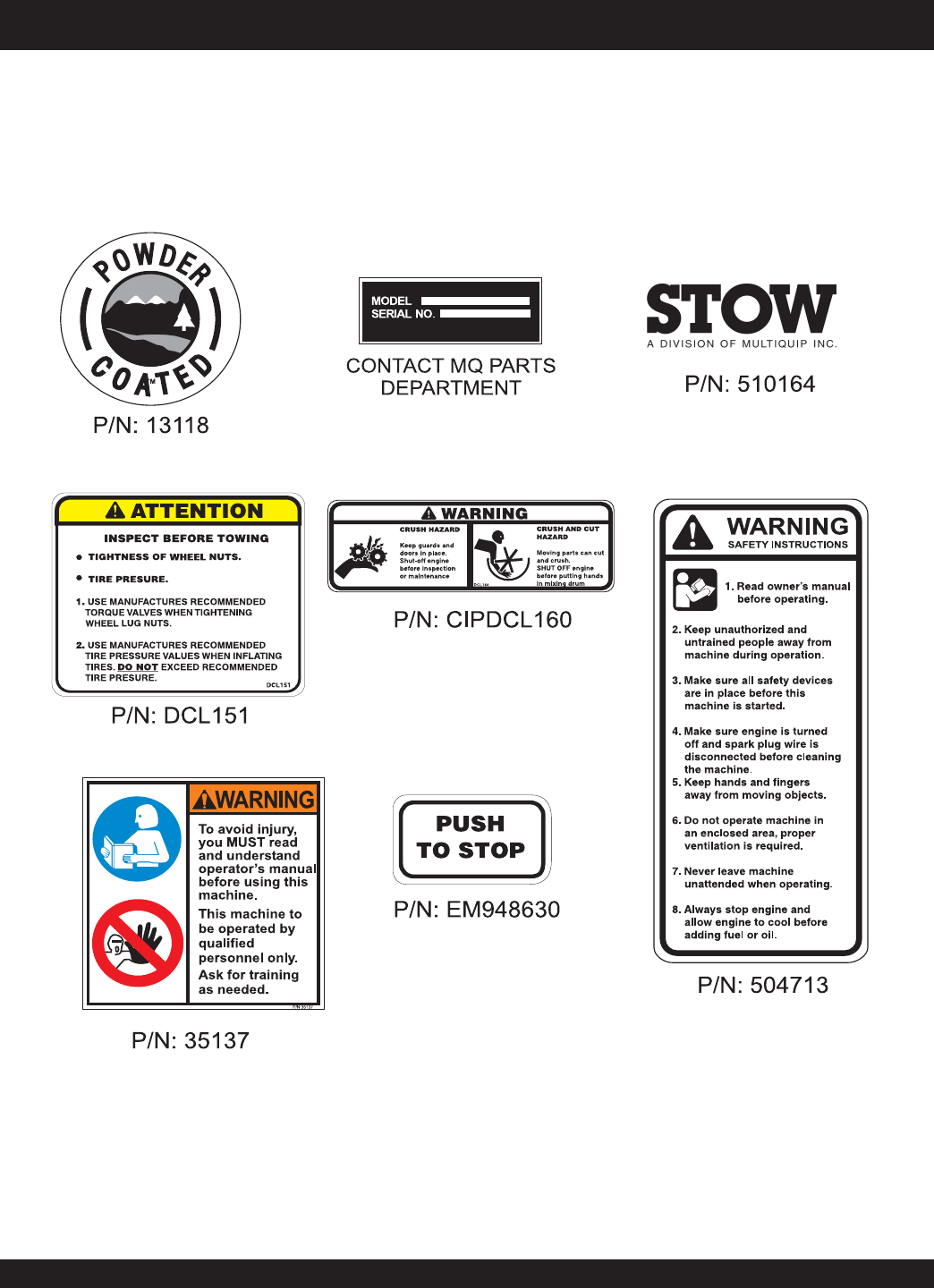
NO PART NO PART NAME QTY.REMARKS
1 512910 DECAL, STOW LOGO 3
2 CIPDCL160 DECAL, CRUSH WARNING 2
3 504713 DECAL, SAFETY INSTRUCTIONS 1
4 EM948630 DECAL, EMERGENCY STOP 1
5 DCL151 DECAL, TOWING INSTRUCTIONS 1
6 13118 DECAL, POWDER COATED 1
7 NAMEPLATE ........................................................ 1 ......... CONTACT PARTS DEPARTMENT
SEE OPERATION AND SAFETY DECAL PAGE.
PAGE 36 — STOW CMS-9S CONCRETE MIXERS — PARTS & OPERATION MANUAL — REV. #6 (01/08/07)
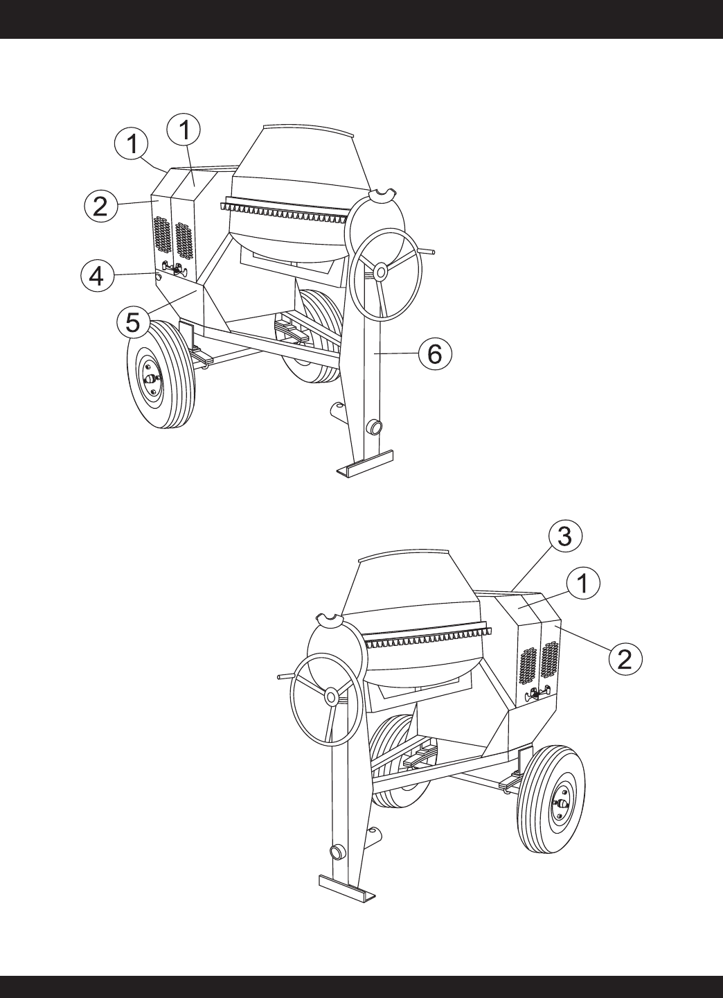
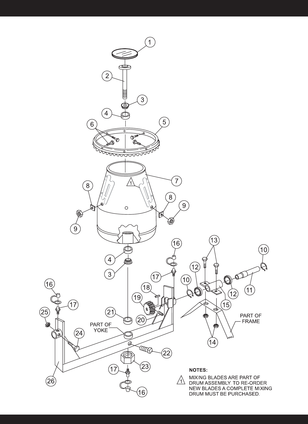
STEEL BARREL ASSY.
STOW CMS-9S — STEEL BARREL

STOW CMS-9S CONCRETE MIXER — PARTS & OPERATION MANUAL — REV. #6 (01/08/07) — PAGE 37
STEEL BARREL ASSY.
NO PART NO PART NAME QTY.REMARK
1 505390 PLUG, EXPANSION 1
2 505469 KING PIN 1
3 510955 SPINDLE BEARING 5/8" CONE 2
4 510956 SPINDLE BEARING CUP 2
5 490338Y RING GEAR 1
6 EM963057 BOLT 3/8" NC 1-1/2" G5 6
7 505473Y BARREL, STEEL 9 CU. FT. 1
8 511729 SHIM 0.10 THICK AR
8 511730 SHIM 0.14 THICK AR
8 511731 SHIM 0.187 THICK AR
8 511732 SHIM 0.25 THICK AR
9 EM969013 NUT, LOCK 3/8” NC 6
10 490962 RING, RETENTION 2
11 502064 DRIVE PINION SHAFT 1
12 492179 PINION SHAFT BEARING 2
13 EM963692 BOLT 1/2" NC X 1-1/2" G5 2
14 492584 LOCKNUT, HEX 1/2" NC 2
15 503597Y HOUSING, JACKSHAFT 1
16 491008 CAP, GREASE FITTING 3
17 EM916001 GREASE FITTING 1/8" NPT ................. 3.............. REPLACES 491698
18 500275 SQUARE KEY 1/4" X 40 MM 1
19 501796 DRIVE PINION 1
20 492468 ALLEN SCREW 5/16 NC 1/2" 2
21 EM505472 SPACER, BARREL 1
22 492491 SET SCREW 1/2" X 1-1/2" NC 1
23 EM968306 NUT, HEX LOWER 1-1/2" NF ................. 1 ............. REPLACES 492579
24 492406 BOLT 5/8" NC X 1-1/4" NC 1
25 EM969023 LOCKNUT, HEX 5/8" 1
26 510593Y YOKE 1
27 490961 RING, RETENTION 1
STOW CMS-9S — STEEL BARREL
PAGE 38 — STOW CMS-9S CONCRETE MIXERS — PARTS & OPERATION MANUAL — REV. #6 (01/08/07)
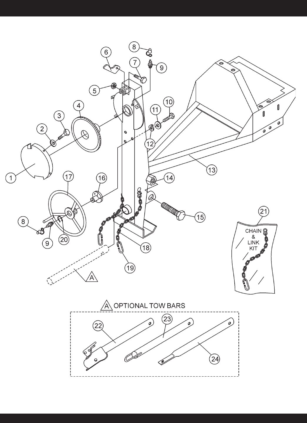
STOW CMS-9S — MAIN FRAME ASSEMBLY
MAIN FRAME ASSY.

STOW CMS-9S CONCRETE MIXER — PARTS & OPERATION MANUAL — REV. #6 (01/08/07) — PAGE 39
STOW CMS-9S — MAIN FRAME ASSEMBLY
MAIN FRAME ASSY.
NO PART NO PART NAME QTY.REMARK
1 500198Y GUARD, GEAR WHEEL 1
2 2101402 WASHER, LOCK 1/4" 4
3 492284 ROUND HEAD BOLT 1/4" NC 3/8 G2" ......... 4.............. REPLACES 492279
4 502063 DUMP GEAR 1
5 492584 NUT, LOCK 1/2" NC 1
6 490895Y DUMP LATCH 1
7 492395 BOLT 1/2" NC X 1-3/4" G5 1
8 EM916001 GREASE FITTING 1/8" NPT ........................ 2.............. REPLACES 491698
9 491008 GREASE CAP 2
10 EM963055 BOLT 3/8" NC X 3/4" G5 3
11 3109092 WASHER, FLAT 3/8" 3
12 0166 A WASHER, LOCK 3/8" 3
13 503595Y FRAME 1
14 EM124 BOLT 1/2"-13 X 4 G5 1
15 10176 LOCK NUT 1/2 NC ........................................ 1.............. REPLACES 492586
16 500167 HANDWHEEL SHAFT 1
17 501808Y HANDWHEEL 1
18 *SAFETY CHAIN 1
19 *01004 CONNECTOR LINK 2
20 490961 RING RETAINING 1
21 13363KIT CHAIN AND LINK KIT 1 INCLUDES ITEMS W/ *
22 HBC-1 BALL HITCH 2-INCH .................................... 1.............. CONTACT UNIT SALES
23 HLC-1 LOOP HITCH ................................................ 1.............. CONTACT UNIT SALES
24 HPC-1 PIN HITCH 1-INCH ....................................... 1.............. CONTACT UNIT SALES
PAGE 40 — STOW CMS-9S CONCRETE MIXERS — PARTS & OPERATION MANUAL — REV. #6 (01/08/07)
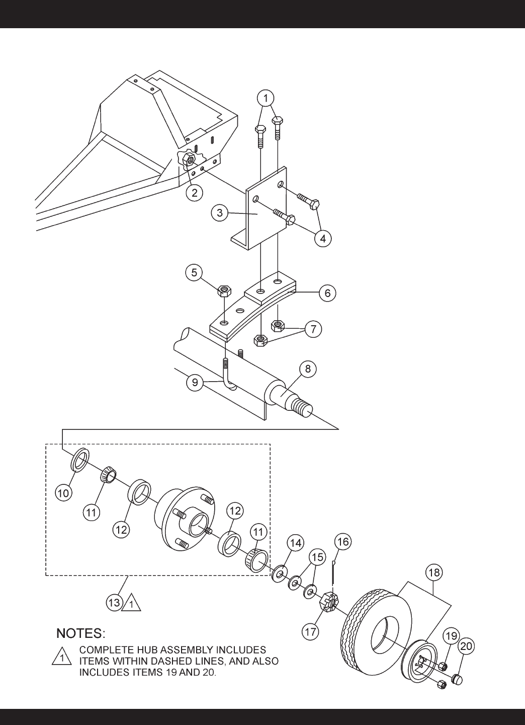
STOW CMS-9S — AXLE ASSEMBLY
AXLE ASSY.

STOW CMS-9S CONCRETE MIXER — PARTS & OPERATION MANUAL — REV. #6 (01/08/07) — PAGE 41
STOW CMS-9S — AXLE ASSEMBLY
AXLE ASSY.
NO PART NO PART NAME QTY.REMARK
1 492395 BOLT 1/2" NC 1-3/4" G5 4
2 EM969023 LOCK NUT 5/8" NC 4
3 501030 SPRING SUPPORT 2
4 492406 BOLT 5/8" NC 1-1/2" G5 4
5 492589 NUT 1/2" NF 4
6 491928 SPRING LEAF 2
7 492584 NUT, HEX 1/2" 4
8 511336 AXLE 1-1/16 SPINDLE 1
8 502039 AXLE 7/8" SPINDLE 1
9 500617 U-CLAMP 2
10*#EM914288 OIL SEAL 2
11*EM903049 BEARING CONE, (7/8" SPINDLE) 4
11#EM903113 BEARING CONE, (1-1/16" SPINDLE) 4
12*#EM903012 BEARING CUP 4
13 3504 HUB ASSY., 4-BOLT (7/8" SPINDLE) ............................. 2 ........... INCLUDES ITEMS W/*
....................................................................................................... REPLACES 493235
13 EM941306 HUB ASSY., 4-BOLT (1-1/16" SPINDLE) ........................ 2 ........... INCLUDES ITEMS W/#
14 EM511159 WASHER, FLAT, .087" THICKNESS 2
15 EM501299 WASHER, FLAT, .135" THICKNESS AR
16 491688 COTTER PIN 1/8" X 1-1/2' 2
17 12426 NUT, SLOTTED HEX JAM (7/8" SPINDLE) .................... 2 ........... REPLACES 3068
17 8164 NUT, SLOTTED HEX JAM (1-1/16" SPINDLE) 2
18 3005 TIRE AND RIM, CARLISE .............................................. 2 ........... BEFORE JANUARY 2006
18 493236C TIRE AND RIM, UNIROYAL ............................................ 2 ........... BEFORE JANUARY 2006
18 516476 TIRE AND RIM, TOWMASTER II ................................... 2 ........... AFTER JANUARY 2006
19*#8115 LUG NUTS 8
20*#3469 DUST CAP 2
PAGE 42 — STOW CMS-9S CONCRETE MIXERS — PARTS & OPERATION MANUAL — REV. #6 (01/08/07)
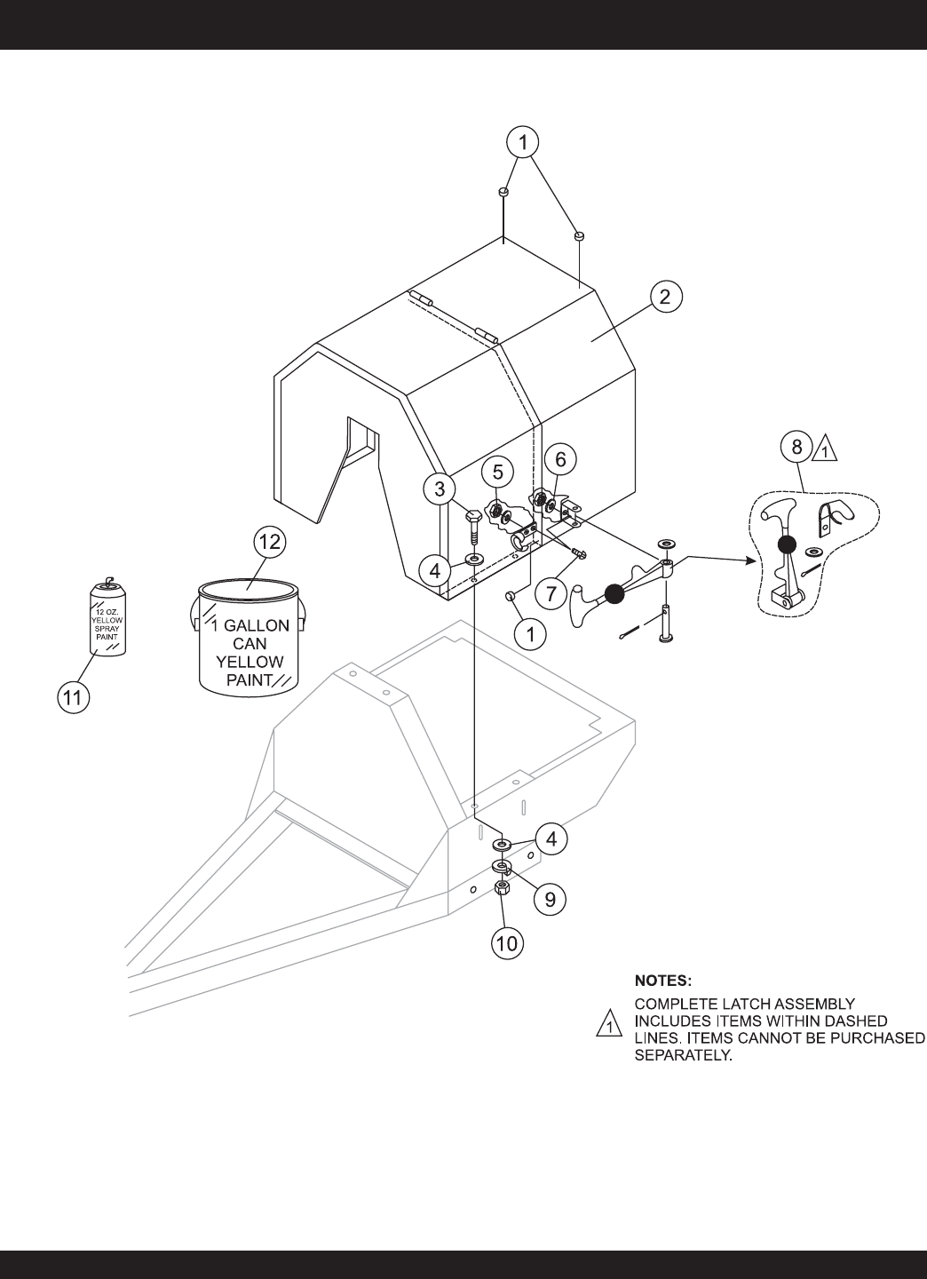
STOW CMS-9S — CABINET ASSEMBLY
CABINET ASSY.

STOW CMS-9S CONCRETE MIXER — PARTS & OPERATION MANUAL — REV. #6 (01/08/07) — PAGE 43
STOW CMS-9S — CABINET ASSEMBLY
CABINET ASSY.
NO PART NO PART NAME QTY.REMARKS
1 490202 RUBBER PROTECTOR 4
2 503598Y CABINET ENGINE ASSY. 1
3 492363 BOLT 5/16" NC X 3/4" G5 4
4 EM923023 WASHER, FLAT 5/16" 8
5 13287 LOCK NUT 8-32 ............................................... 6 ............... REPLACEMENT PART ONLY
6 2203 WASHER, FLAT #10 ........................................ 6 ............... REPLACEMENT PART ONLY
7 1307 RHMS 8-32 X 1/2" ........................................... 6 ............... REPLACEMENT PART ONLY
8 491010 LATCH ASSY., COMPLETE 2
9 EM923343 WASHER, LOCK 5/16" 4
10 492553 NUT 5/16"" NC G5 4
11 RAL1003S PAINT, SPRAY CAN 12 OZ., YELLOW AR
12 RAL1003G PAINT, GALLON CAN, YELLOW AR
PAGE 44 — STOW CMS-9S CONCRETE MIXERS — PARTS & OPERATION MANUAL — REV. #6 (01/08/07)
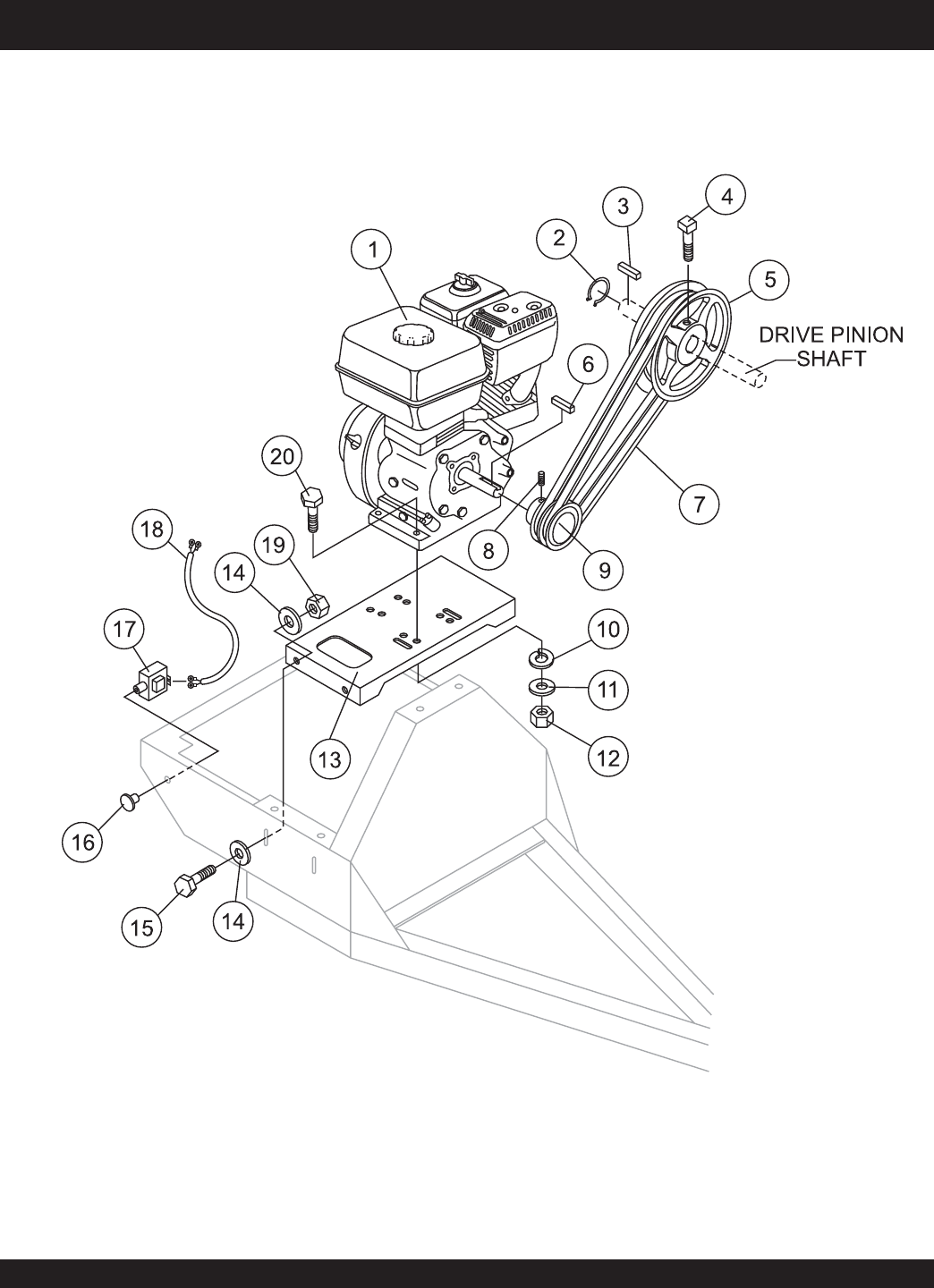
STOW CMS-9S — GAS ENGINE MOUNTING PLATE ASSEMBLY
GAS ENGINE MOUNTING PLATE ASSY.

STOW CMS-9S CONCRETE MIXER — PARTS & OPERATION MANUAL — REV. #6 (01/08/07) — PAGE 45
STOW CMS-9S — GAS ENGINE MOUNTING PLATE ASSEMBLY
GAS ENGINE MOUNTING PLATE ASSY.
NO PART NO PART NAME QTY.REMARKS
1 GX240K1HA2 ENGINE, HONDA 8.0 HP 1
1 EH252YR000 ENGINE, ROBIN 8.5 HP 1
2 490956 RING, RETAINING 1
3 500275 SQUARE KEY 1
4 492468 SET SCREW 5/16" NC X 3/4" 1
5 492078 UPPER PULLEY 1
6 501019 SQUARE KEY 3/16" X 45 MM 1
7 503859 V-BELT A-38, HONDA 2
7 491112 V-BELT A-40, ROBIN 2
8 492468 ALLEN SCREW 5/16" NC X 1/2" 1
9 492075 LOWER PULLEY 1
10 EM923343 WASHER, LOCK 5/16" 4
11 EM923023 WASHER, FLAT 5/16" 4
12 492553 NUT, HEX 5/16 X18 NC G5 4
13 502041 BASE PLATE ENGINE 1
14 492600 WASHER, FLAT 1/2" 8
15 EM963692 BOLT, HEX 1/2" NC 1-1/2" G5 4
16 29174-001 BUTTON, STOP 1
17 EM940734 SWITCH, STOP ........................................... 1 ........... REPLACES 491845
18 510573 ENGINE CABLE HARNESS 1
19 492584 LOCKNUT 1/2" 4
20 492367 BOLT 5/16" X 1-3/4" G5 4
PAGE 46 — STOW CMS-9S CONCRETE MIXERS — PARTS & OPERATION MANUAL — REV. #6 (01/08/07)
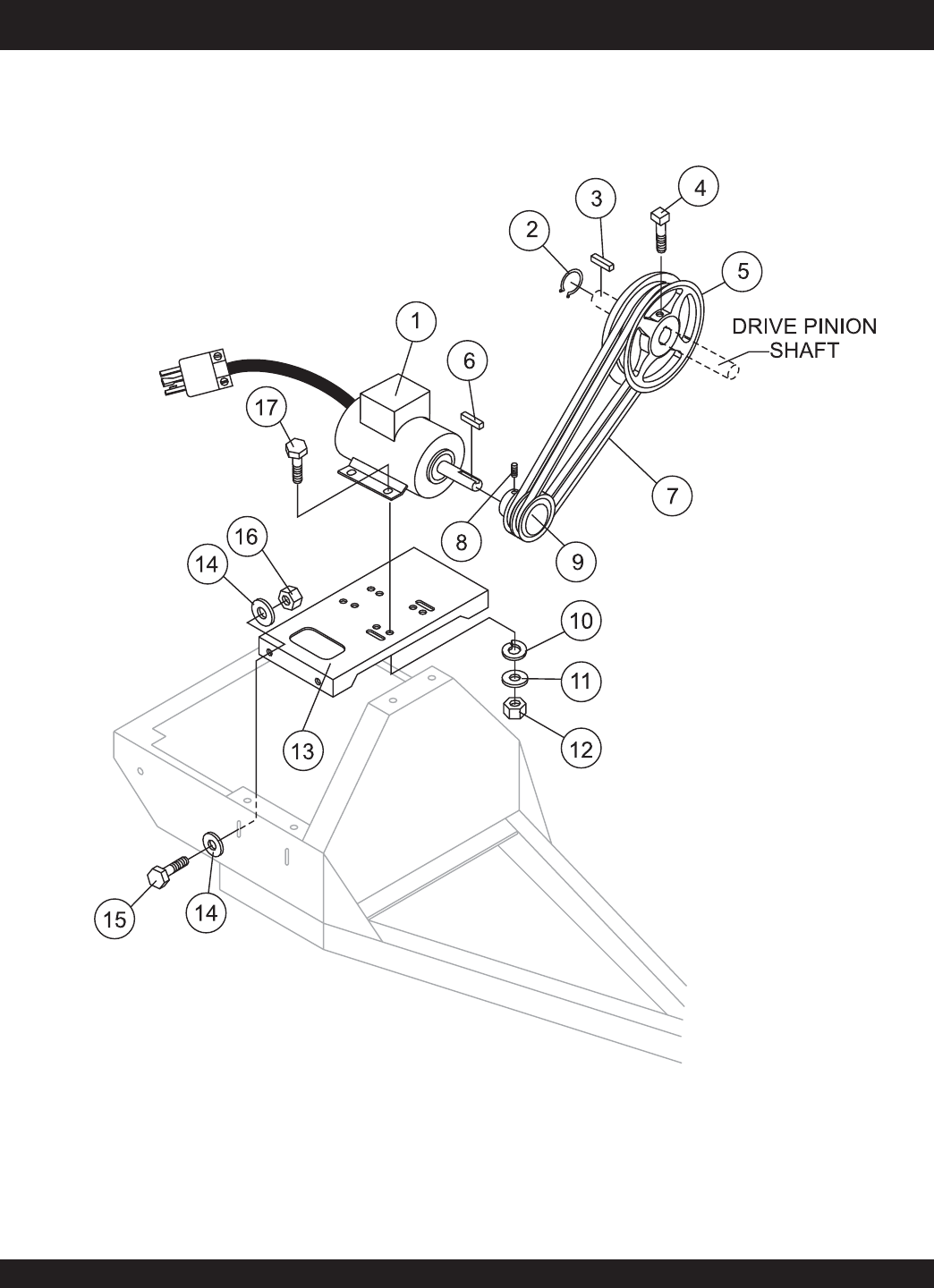
STOW CMS-9S — ELECTRIC MOTOR MOUNTING PLATE ASSEMBLY
ELECTRIC MOTOR MOUNTING PLATE ASSY.

STOW CMS-9S CONCRETE MIXER — PARTS & OPERATION MANUAL — REV. #6 (01/08/07) — PAGE 47
STOW CMS-9S — ELECTRIC MOTOR MOUNTING PLATE ASSEMBLY
ELECTRIC MOTOR MOUNTING PLATE ASSY.
NO PART NO PART NAME QTY.REMARKS
1 P145K17DB45A MOTOR, ELECTRIC 1.5 HP 1
2 490956 RING, RETAINING 1
3 500275 SQUARE KEY 1
4 492468 SET SCREW 5/16" NC X 3/4" 1
5 502210 UPPER PULLEY 1
6 501019 SQUARE KEY 3/16" X 45 MM 1
7 EM900267 V-BELT, A45 2
8 492468 ALLEN SCREW 5/16" NC X 1/2" 1
9 502213 DRIVE PULLEY 1
10 EM923343 WASHER, LOCK 5/16" 4
11 EM923023 WASHER, FLAT 5/16" 4
12 2105164 NUT, HEX 5/16 X18 NC G5 4
13 503599 BASE PLATE ENGINE 1
14 492600 WASHER, FLAT 1/2" 8
15 EM963692 BOLT, HEX 1/2" NC 1-1/2" G5 4
16 492584 LOCKNUT 1/2" 4
17 0202 BOLT 5/16" X 1" G5 4
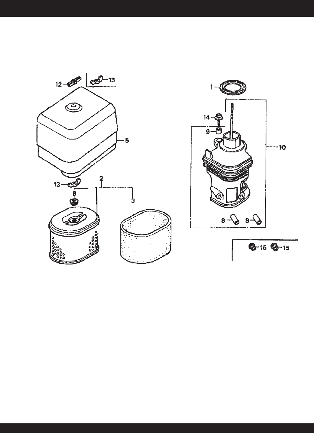
PAGE 48 — STOW CMS-9S CONCRETE MIXERS — PARTS & OPERATION MANUAL — REV. #6 (01/08/07)
HONDA GX240K1HA2 ENGINE — AIR CLEANER ASSY.
AIR CLEANER ASSY.

STOW CMS-9S CONCRETE MIXER — PARTS & OPERATION MANUAL — REV. #6 (01/08/07) — PAGE 49
HONDA GX240K1HA2 ENGINE — AIR CLEANER ASSY.
AIR CLEANER ASSY.
NO. PART NO. PART NAME QTY.REMARKS
1 16271ZE2000 GASKET, ELBOW ..................................... 1 ............. INCLUDES ITEM W/*
2 17210ZE2515 ELEMENT, AIR CLEANER, DUAL 1
3 *17218ZE2505 FILTER, OUTER 1
5 17231ZH9820 COVER, AIR CLEANER 1
6 17232891000 GROMMET, AIR CLEANER 1
8 # 17238ZE2310 COLLAR, AIR CLEANER 2
9 # 17239ZE1000 COLLAR B, AIR CLEANER 1
10 17410ZE2020 ELBOW COMP., AIR CLEANER ............... 1 ............. INCLUDES ITEM W/#
12 0037806000 WINGNUT 6MM 1
13 90325044000 WINGNUT, TOOL BOX SETTING 2
14 90009ZE2003 BOLT- WASHER 6 X 22 1
15 9405006000 NUT, FLANGE 6MM 2
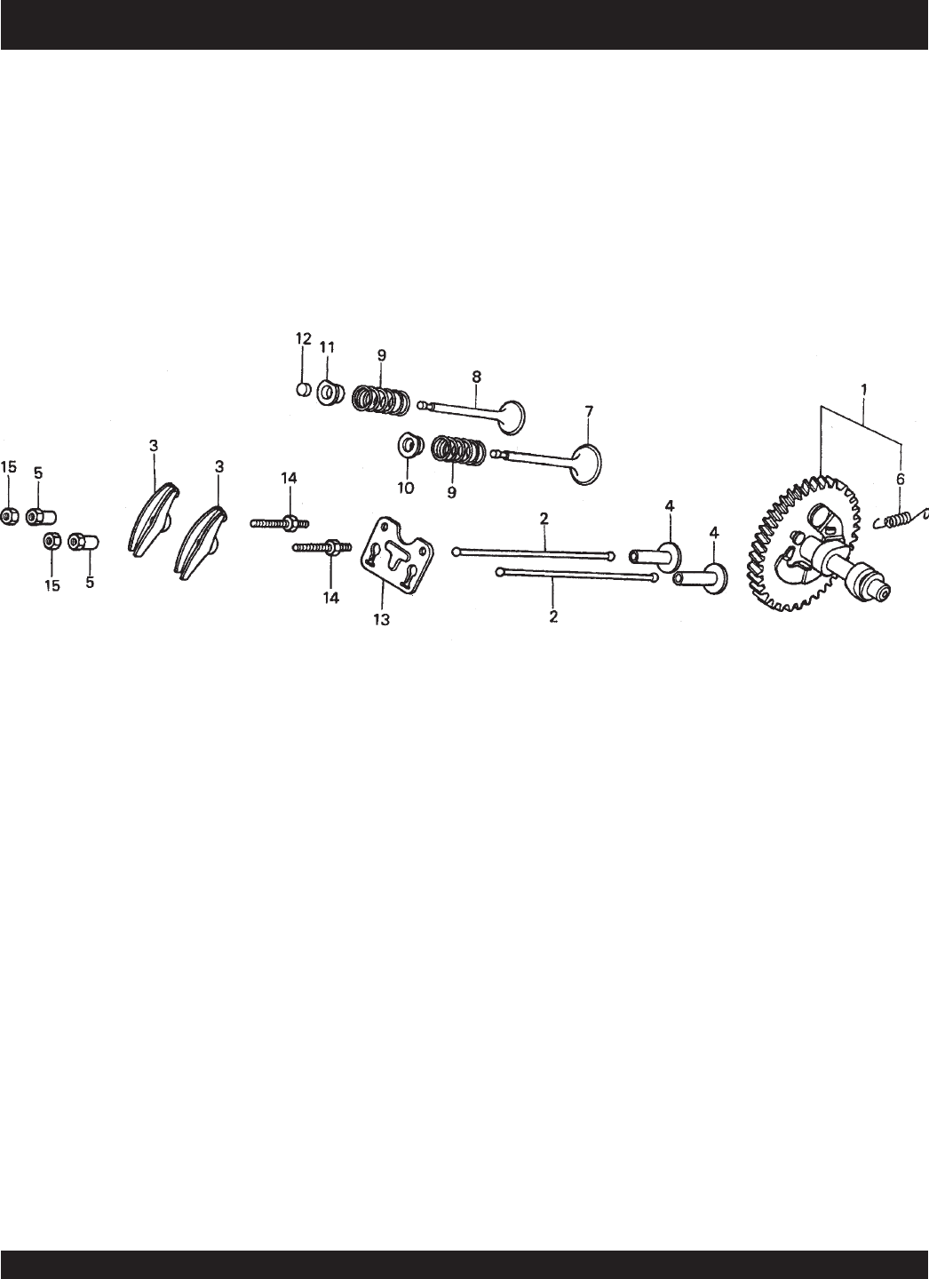
PAGE 50 — STOW CMS-9S CONCRETE MIXERS — PARTS & OPERATION MANUAL — REV. #6 (01/08/07)
HONDA GX240K1HA2 ENGINE — CAMSHAFT ASSY.
CAMSHAFT ASSY.

STOW CMS-9S CONCRETE MIXER — PARTS & OPERATION MANUAL — REV. #6 (01/08/07) — PAGE 51
HONDA GX240K1HA2 ENGINE — CAMSHAFT ASSY.
CAMSHAFT ASSY.
NO. PART NO. PART NAME QTY.REMARKS
1 14100ZE2W01 CAMSHAFT ASSY. ................................... 1 ............. INCLUDES ITEM W/*
1 14100ZE2306 CAMSHAFT 1
2 14410ZE2013 ROD PUSH 2
3 14431ZE2010 ARM VALVE ROCKER 2
4 14441ZE2000 LIFTER VALVE 2
5 14451ZE1013 PIVOT ROCKER ARM 2
6*14568ZE1000 SPRING, WEIGHT RETURN 1
7 14711ZE2000 VALVE, IN. 1
8 14721ZE2000 VALVE, EX. 1
9 14751ZE2003 SPRING, VALVE 2
10 14771ZE2000 RETAINER, IN. VALVE SPRING 1
11 14773ZE2000 RETAINER, EX. VALVE SPRING 1
12 14781ZE2000 ROTATOR, VALVE 1
13 14791ZE2010 PLATE, PUSH ROD GUIDE 1
14 90012ZE0010 BOLT, PIVOT 8MM 2
15 90206ZE1000 NUT, PIVOT ADJ. 2
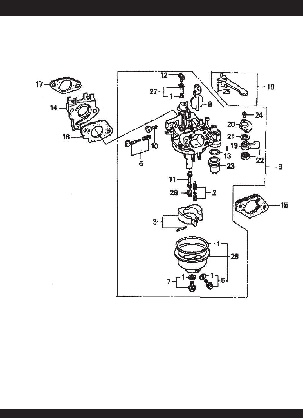
PAGE 52 — STOW CMS-9S CONCRETE MIXERS — PARTS & OPERATION MANUAL — REV. #6 (01/08/07)
HONDA GX240K1HA2 ENGINE — CARBURETOR ASSY.
CARBURETOR ASSY.

STOW CMS-9S CONCRETE MIXER — PARTS & OPERATION MANUAL — REV. #6 (01/08/07) — PAGE 53
HONDA GX240K1HA2 ENGINE — CARBURETOR ASSY.
CARBURETOR ASSY.
NO. PART NO. PART NAME QTY.REMARKS
1*+16010ZE2812 GASKET SET 1
2*16011ZA0931 VALVE SET, FLOAT 1
3*16013ZA0931 FLOAT SET 1
5*16016ZHW01 SCREW SET 1
6*+16024ZE1811 SCREW SET, DRAIN 1
7*+16028ZE0005 SCREW SET B 1
8*16028ZE2005 CHOKE SET 1
9*16100ZE2W71 CARBURETOR ASSY. ................... 1 ..... INCLUDES ITEMS W/*
10*16124ZE0005 SCREW, THROTTLE STOP 1
11*16166ZE2W70 NOZZLE, MAIN 1
12*16075GHBB00 COLLAR, SET 1
13*16075GHBB00 O-RING 1
14 16211ZE2000 INSULATOR, CARB. 1
15 16220ZA0702 SPACER COMP., CARB. 1
16 16221ZA0800 GASKET, CARBURETOR 1
17 16223ZA0800 GASKET, INSULATOR 1
18 16610ZE1000 LEVER COMP., CHOKE, STD. 1
19*16953ZE1812 LEVER, VALVE 1
20*16954ZE1811 PLATE, LEVER SETTING 1
21*16956ZE1811 SPRING, VALVE LEVER 1
22*16957ZE1812 GASKET, VALVE 1
23*16967ZE0811 CUP, FUEL STRAINER 1
24*93500030060H SCREW, PAN 3 X 6 2
25 9430520122 PIN, SPRING 2 X 12 1
26*99101ZH70820 JET, MAIN #82, OPTIONAL 1
26*99101ZH70850 JET, MAIN #85, OPTIONAL 1
26*99101ZH80880 JET, MAIN #88 1
27*99204ZE20400 JET SET, PILOT #40 1
28*16015ZE8005 CHAMBER SET, FLOAT ................ 1 ..... INCLUDES ITEMS W/+
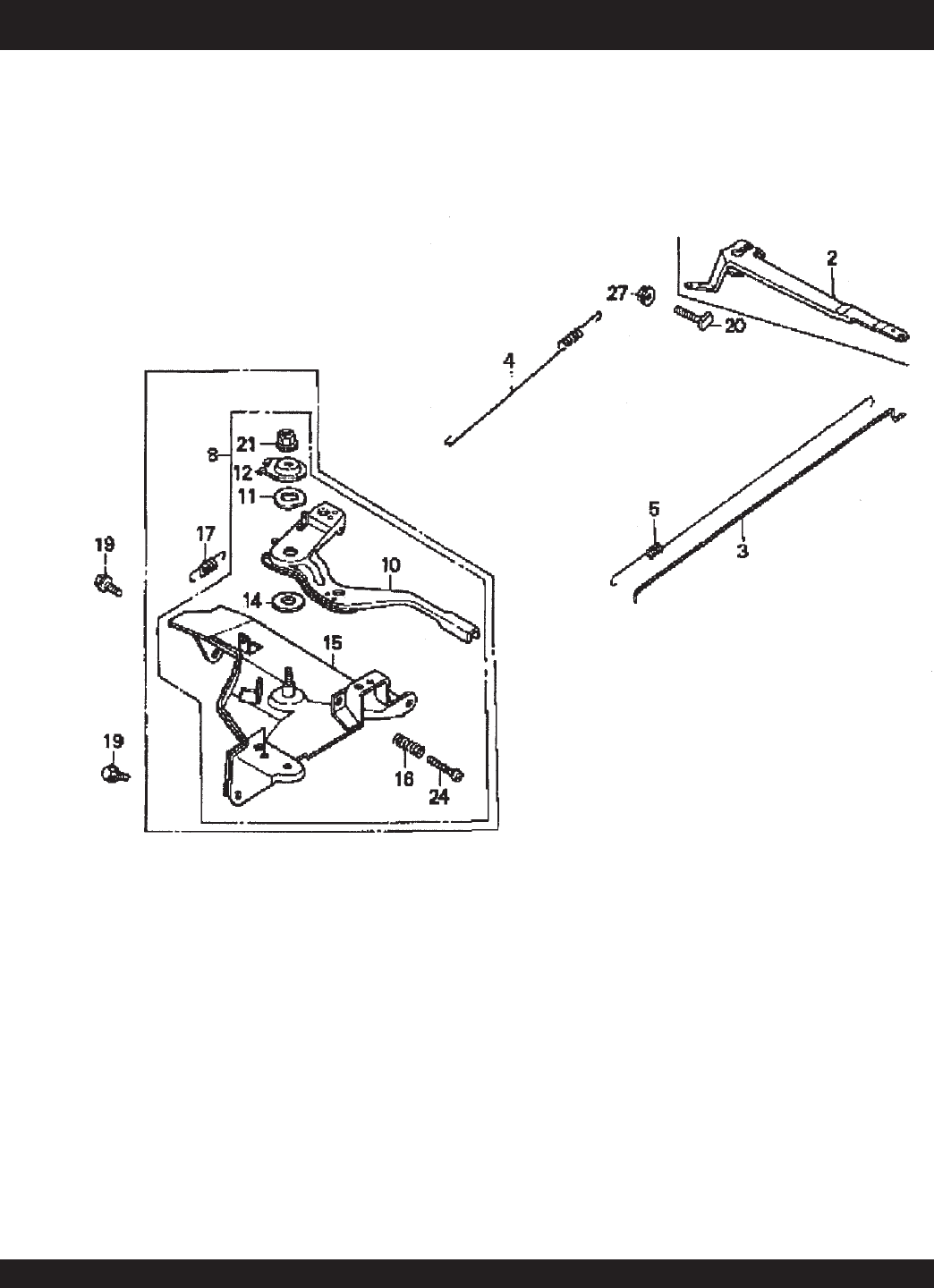
PAGE 54 — STOW CMS-9S CONCRETE MIXERS — PARTS & OPERATION MANUAL — REV. #6 (01/08/07)
CONTROL ASSY.
HONDA GX240K1HA2 ENGINE — CONTROL ASSY.

STOW CMS-9S CONCRETE MIXER — PARTS & OPERATION MANUAL — REV. #6 (01/08/07) — PAGE 55
HONDA GX240K1HA2 ENGINE — CONTROL ASSY.
CONTROL ASSY.
NO. PART NO. PART NAME QTY.REMARKS
2 16551ZE2000 ARM, GOVERNOR 1
3 16555ZE2000 ROD, GOVERNOR 1
4 16561ZE2000 SPRING, GOVERNOR 1
5 16571ZE2000 SPRING, THROTTLE RETURN 1
8 16570ZE2W00 CONTROL ASSEMBLY ................................ 1 .......... INCLUDES ITEMS W/*
10*16571ZE2W00 LEVER, CONTROL 1
11*16574ZE1000 SPRING, LEVER 1
12*16575ZE2W00 WASHER, CONTROL LEVER 1
14*16578ZE1000 SPACER, CONTROL LEVER 1
15*16581ZE2W00 BASE, CONTROL 1
16*16584883300 SPRING, CONTROL ADJUSTING 1
19 90013883000 BOLT, FLANGE (6 X 12) (CT200) 2
20 90015ZE5010 BOLT, GOVERNOR ARM 1
21*90114SA0000 NUT, SELF- LOCK (6MM) 1
24*93500050280A SCREW, PAN (5 X 28) 1
27 9405006000 NUT, FLANGE 1
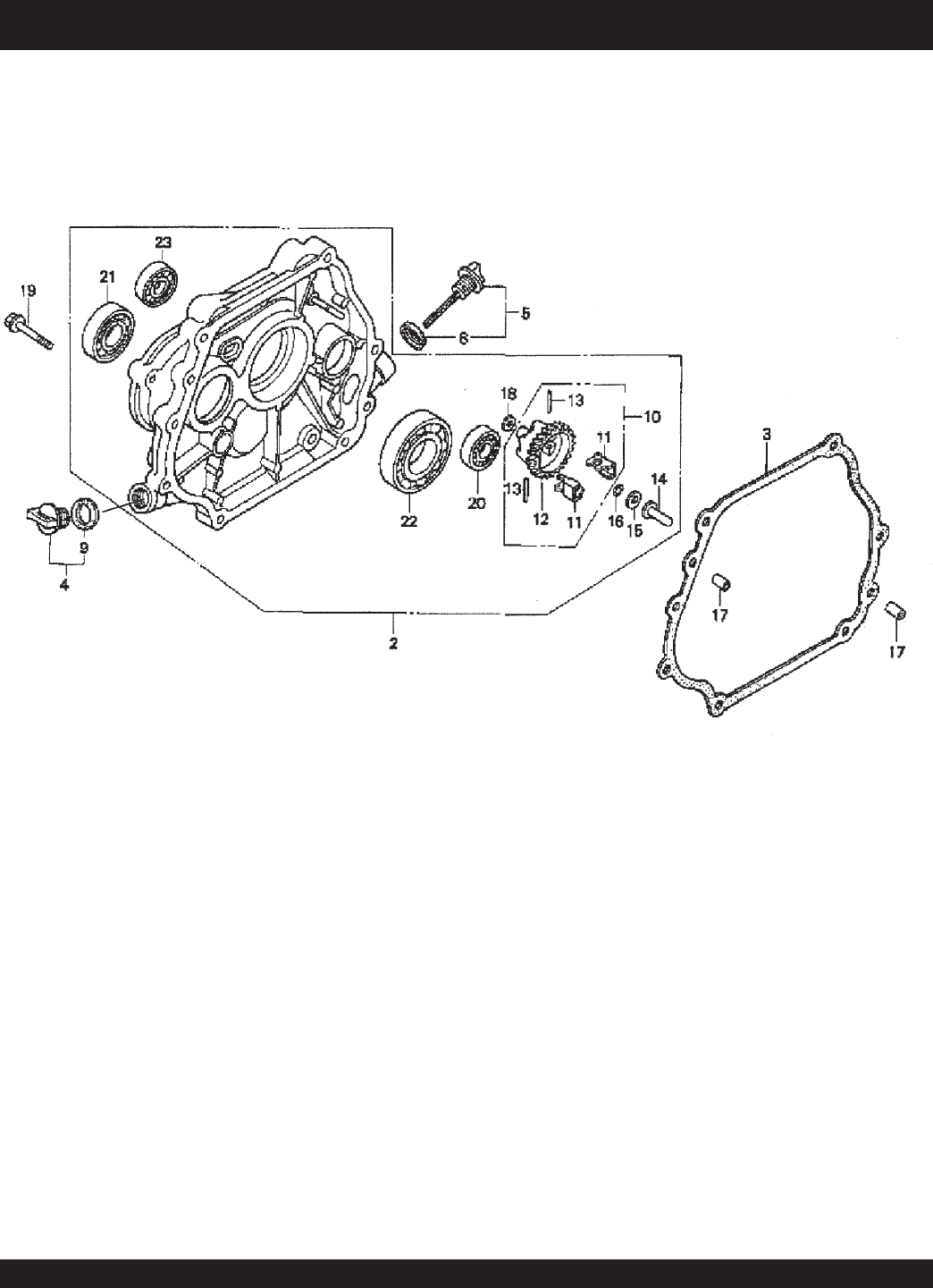
PAGE 56 — STOW CMS-9S CONCRETE MIXERS — PARTS & OPERATION MANUAL — REV. #6 (01/08/07)
CRANKCASE COVER ASSY.
HONDA GX240K1HA2 ENGINE — CRANKCASE COVER ASSY.

STOW CMS-9S CONCRETE MIXER — PARTS & OPERATION MANUAL — REV. #6 (01/08/07) — PAGE 57
HONDA GX240K1HA2 ENGINE — CRANKCASE COVER ASSY.
CRANKCASE COVER ASSY.
NO. PART NO. PART NAME QTY.REMARKS
2 11400ZE2621 COVER ASSY., CRANKCASE ..................... 1 ........... INCLUDES ITEMS W/*
(H- TYPE) (BALANCER)
3 11381ZE2801 GASKET, CASE COVER 1
4 15600ZG4003 CAP ASSY., OIL FILLER ............................. 1 ........... INCLUDES ITEMS W/#
5 15600735003 CAP ASSY., OIL FILLER ............................. 1 ........... INCLUDES ITEMS W/%
8%15625ZE1003 GASKET, OIL FILLER CAP 1
9#15625ZE1003 GASKET, OIL FILLER CAP 1
10 16510ZE2811 GOVERNOR ASSEMBLY (BALANCER) ...... 1........... INCLUDES ITEMS W/+
11* +16511ZE2000 WEIGHT, GOVERNOR 2
12* +16512ZE2811 HOLDER, GOVERNOR WEIGHT 1
13* +16513ZE2000 PIN, GOVERNOR WEIGHT 2
14*16531ZE2000 SLIDER, GOVERNOR 1
15*90473147000 WASHER (6 X 16) 1
16*90602ZE1000 CLIP, GOVERNOR HOLDER 1
17 90701HC4000 PIN, DOWEL (8 X 12) 2
18*58176 WASHER, PLAIN (6MM) 1
19 957010803500 BOLT, FLANGE (8 X 35) 7
20*961006202000 BEARING, RADIAL BALL (6202) 1
21*961006204000 BEARING, RADIAL BALL (6204) 1
22*961006206000 BEARING, RADIAL BALL (6206) 1
23*961006302000 BEARING, RADIAL BALL (6302) 1
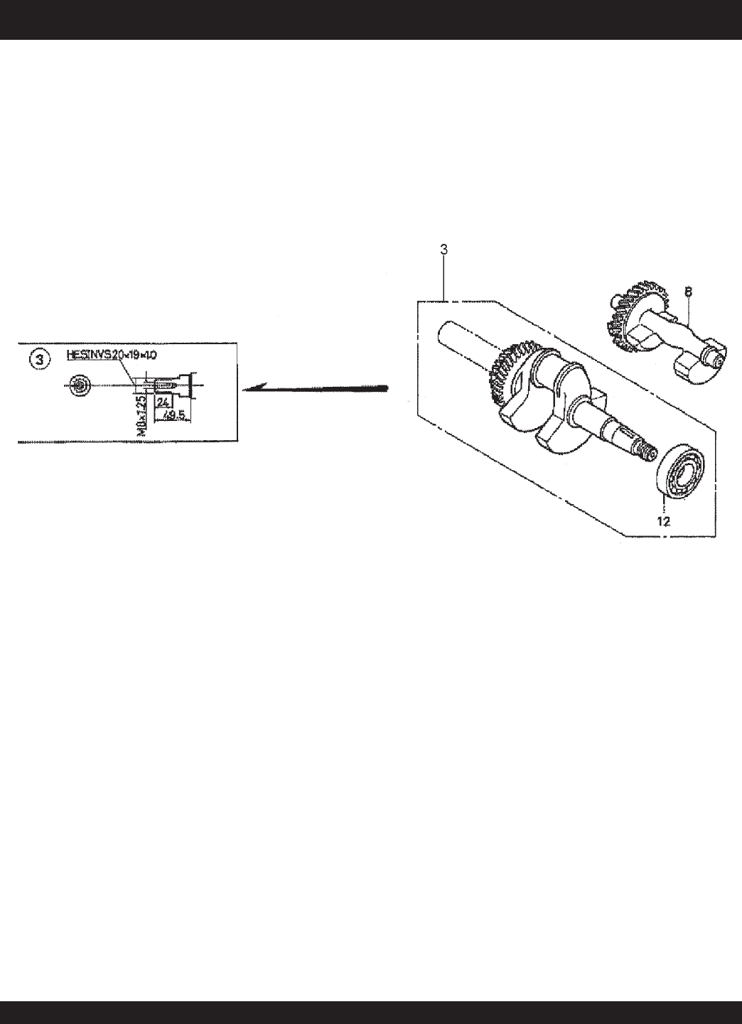
PAGE 58 — STOW CMS-9S CONCRETE MIXERS — PARTS & OPERATION MANUAL — REV. #6 (01/08/07)
CRANKSHAFT ASSY.
HONDA GX240K1HA2ENGINE — CRANKSHAFT ASSY.

STOW CMS-9S CONCRETE MIXER — PARTS & OPERATION MANUAL — REV. #6 (01/08/07) — PAGE 59
HONDA GX240K1HA2ENGINE — CRANKSHAFT ASSY.
CRANKSHAFT ASSY.
NO. PART NO. PART NAME QTY.REMARKS
3 13320ZE2611 CRANKSHAFT (L- TYPE) ............................. 1 .......... INCLUDES ITEM W/*
8 13351ZE2010 WEIGHT BALANCER 1
12*961006206000 BEARING, RADIAL BALL (6206) 1
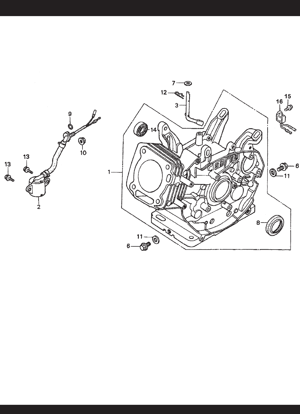
PAGE 60 — STOW CMS-9S CONCRETE MIXERS — PARTS & OPERATION MANUAL — REV. #6 (01/08/07)
CYLINDER BARREL ASSY.
HONDA GX240K1HA2 ENGINE — CYLINDER BARREL ASSY.

STOW CMS-9S CONCRETE MIXER — PARTS & OPERATION MANUAL — REV. #6 (01/08/07) — PAGE 61
HONDA GX240K1HA2 ENGINE — CYLINDER BARREL ASSY.
CYLINDER BARREL ASSY.
NO. PART NO. PART NAME QTY.REMARKS
1 12000ZE2834 CYLINDER ASSY., BALANCER + OIL ALERT ...... 1 .......... INCLUDES ITEMS W/*
2 15510ZE2043 SWITCH ASSY., OIL LEVEL 1
3 16541ZE2010 SHAFT, GOVERNOR ARM 1
6 90131896650 BOLT, DRAIN PLUG 2
7 90446KE1000 WASHER 8.2 X17X0.8 1
8*91201890003 OIL SEAL 30X46X8 1
9 91353671003 O-RING 14MM ARAI 1
10 9405010000 NUT FLANGE 10MM 1
11 031112230 WASHER, DRAIN PLUG 12MM 2
12 9425110000 PIN, LOCK 10MM 1
13 957010601200 BOLT, FLANGE 6X12 2
14*961006202000 BEARING, RADIAL BALL 6202 1
15 90013883000 BOLT, FLANGE 6X12 CT200 1
16 34150ZH7003 ALERT UNIT, OIL 1
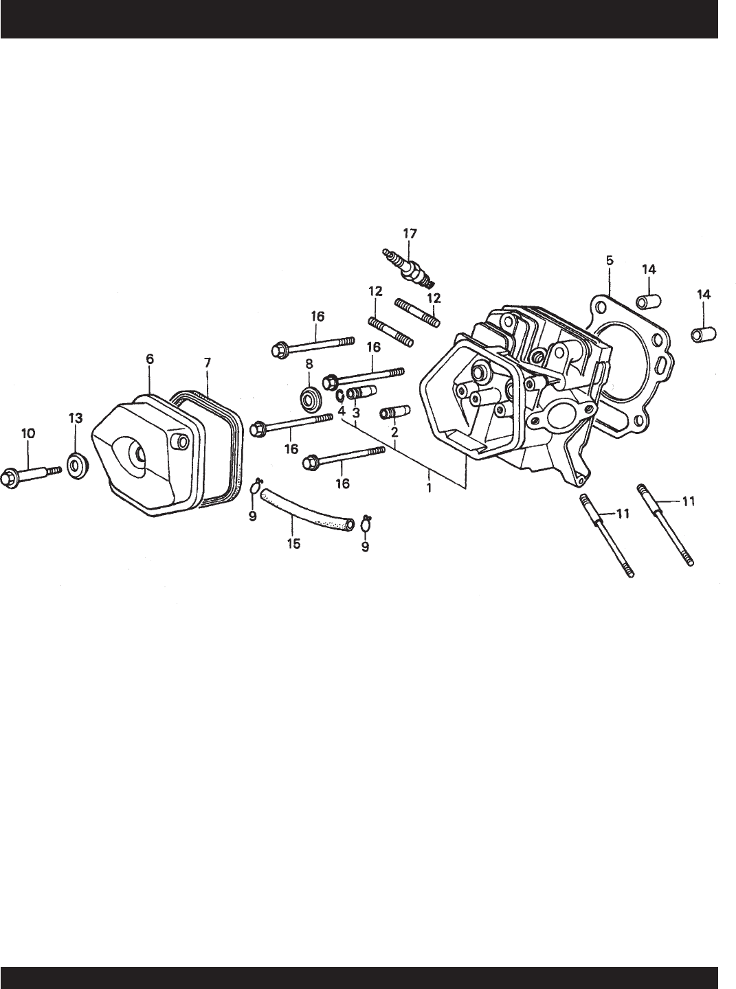
PAGE 62 — STOW CMS-9S CONCRETE MIXERS — PARTS & OPERATION MANUAL — REV. #6 (01/08/07)
HONDA GX240K1HA2 ENGINE — CYLINDER HEAD ASSY.
CYLINDER HEAD ASSY.

STOW CMS-9S CONCRETE MIXER — PARTS & OPERATION MANUAL — REV. #6 (01/08/07) — PAGE 63
HONDA GX240K1HA2 ENGINE — CYLINDER HEAD ASSY.
CYLINDER HEAD ASSY.
NO. PART NO. PART NAME QTY.REMARKS
1 12200ZH9000 CYLINDER HEAD COMP. ....................................... 1 .......... INCLUDES ITEMS W/*
2*12204ZE2306 GUIDE, VALVE, OS, OPTIONAL 1
3*12205ZE2305 GUIDE, EX. VALVE, OS, OPTIONAL 1
4*12216ZE2300 CLIP, VALVE GUIDE 1
5 12251ZE2800 GASKET, CYLINDER HEAD 1
6 12310ZE2020 COVER COMP., HEAD 1
7 12391ZE2020 GASKET, CYLINDER HEAD COVER 1
8 14775ZE2010 SEAT, VALVE SPRING 1
10 90014ZE2000 BOLT, HEAD COVER 1
11 90042ZE2000 BOLT, STUD 8X123 2
12 92900080320E BOLT, STUD 8X47 2
13 90441ZE2010 WASHER COMP., HEAD COVER 1
14 9430112200 PIN A, DOWEL 12X20 2
15 950051100130M BULK HOSE, VACUUM 11X1000, 11X100 1
16 957011008000 BOLT, FLANGE 10X80 4
17 9807956846 SPARK PLUG, BPR6ES, NGK 1
17 9807956855 SPARK PLUG, W20EPR-U, DENSO 1
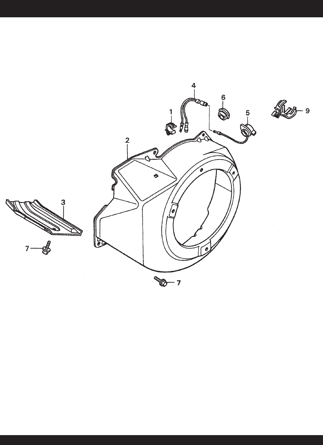
PAGE 64 — STOW CMS-9S CONCRETE MIXERS — PARTS & OPERATION MANUAL — REV. #6 (01/08/07)
HONDA GX240K1HA2 ENGINE — FAN COVER ASSY.
FAN COVER ASSY.

STOW CMS-9S CONCRETE MIXER — PARTS & OPERATION MANUAL — REV. #6 (01/08/07) — PAGE 65
HONDA GX240K1HA2 ENGINE — FAN COVER ASSY.
FAN COVER ASSY.
NO. PART NO. PART NAME QTY.REMARKS
1 16731ZE2003 CLIP, TUBE 1
2 19610ZE2010ZC COVER COMP., FAN *NH1* BLACK 1
3 19631ZE2D00 SHROUD 1
4 32197ZH8003 SUB-HARNESS 1
5 36100ZE1015 SWITCH ASSY., ENGINE STOP 1
7 90013883000 BOLT, FLANGE 6X12, CT200 6
9 90684ZA0601 CLIP, WIRE HARNESS 1
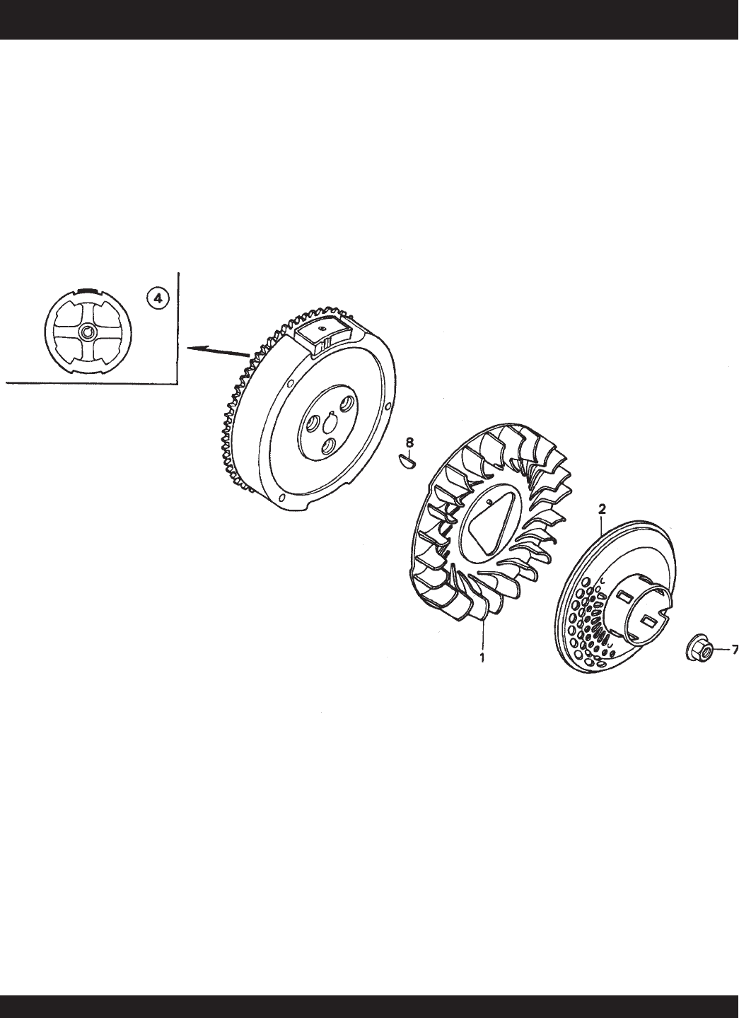
PAGE 66 — STOW CMS-9S CONCRETE MIXERS — PARTS & OPERATION MANUAL — REV. #6 (01/08/07)
HONDA GX240K1HA2 ENGINE — FLYWHEEL ASSY.
FLYWHEEL ASSY.

STOW CMS-9S CONCRETE MIXER — PARTS & OPERATION MANUAL — REV. #6 (01/08/07) — PAGE 67
HONDA GX240K1HA2 ENGINE — FLYWHEEL ASSY.
FLYWHEEL ASSY.
NO. PART NO. PART NAME QTY.REMARKS
1 19511ZE2000 FAN, COOLING 1
2 28450ZE2W11 PULLEY COMP., STARTER, SCREEN GRID 1
4 31100ZE2010 FLYWHEEL COMP. 1
7 90201ZE3V00 NUT, SPECIAL 16MM 1
8 90741ZE2000 KEY, SPECIAL WOODRUFF 25X18 1
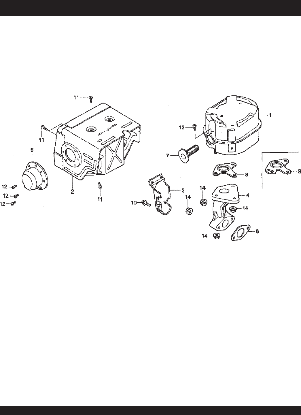
PAGE 68 — STOW CMS-9S CONCRETE MIXERS — PARTS & OPERATION MANUAL — REV. #6 (01/08/07)
HONDA GX240K1HA2 ENGINE — MUFFLER ASSY.
MUFFLER ASSY.

STOW CMS-9S CONCRETE MIXER — PARTS & OPERATION MANUAL — REV. #6 (01/08/07) — PAGE 69
HONDA GX240K1HA2 ENGINE — MUFFLER ASSY.
MUFFLER ASSY.
NO. PART NO. PART NAME QTY.REMARKS
1 18310ZE2W00 MUFFLER 1
2 18320ZE2W01 PROTECTOR, MUFFLER 1
3 18323ZE2W00 PROTECTOR, EX. PIPE 1
4 18330ZE2W00 PIPE, EX. 1
5 18331ZE2810 CAP, MUFFLER 1
6 18333ZK6Y00 GASKET, EX. PIPE 1
7 18355ZE2010 ARRESTER, SPARK 1
8 18381ZE2W10 GASKET, MUFFLER (ARRESTER) 1
9 18381ZE2800 GASKET, MUFFLER 1
10 90013883000 BOLT, FLANGE (6 X 12) (CT200) 1
11 90050ZE1000 SCREW, TAPPING (5 X 8) 6
12 90055ZE1000 SCREW, TAPPING (4 X 6) 3
13 90050ZE1000 SCREW, TAPPING (5 X 8) (OPTIONAL) 1
14 9405008000 NUT, FLANGE (8MM) 5
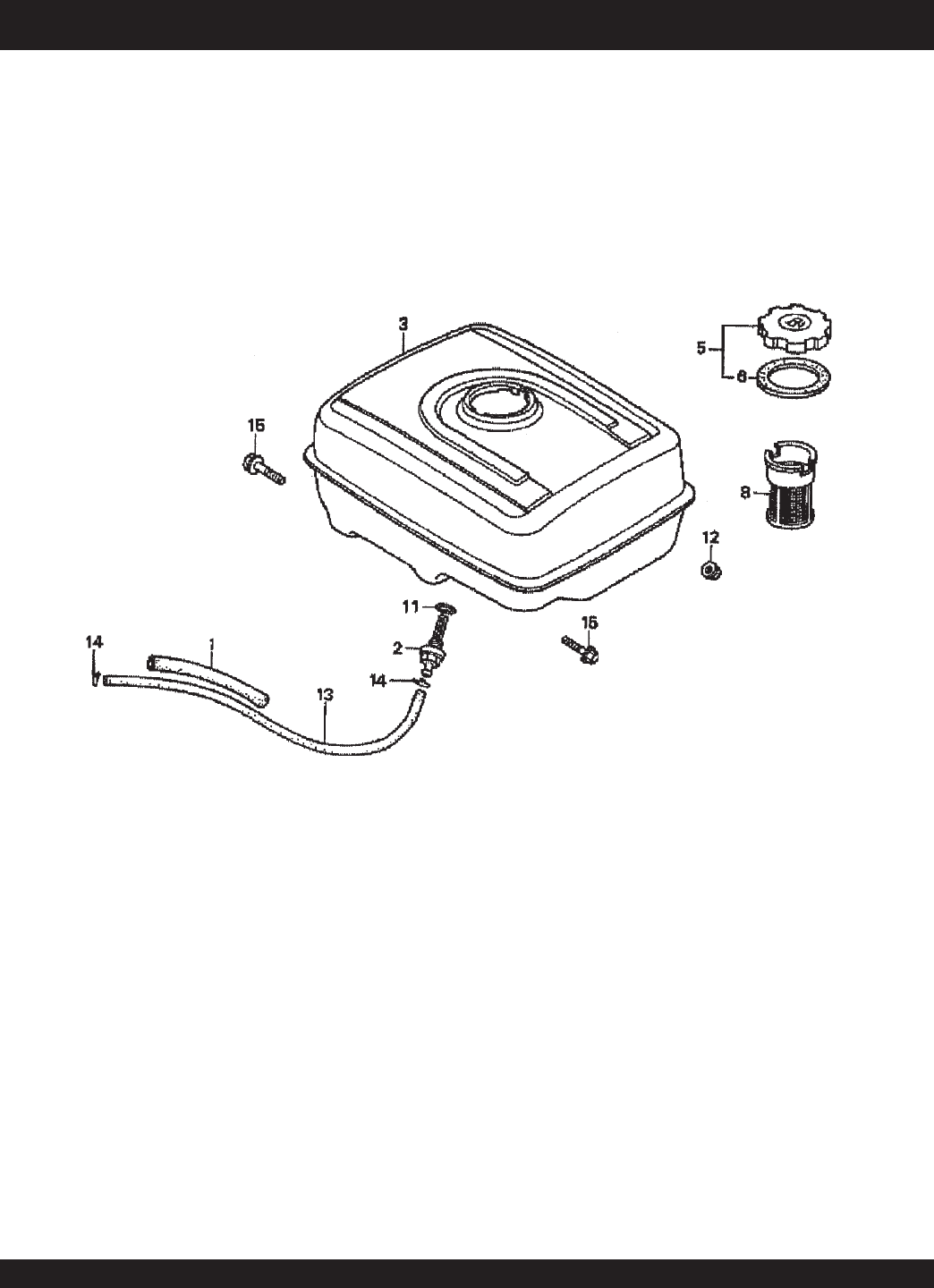
PAGE 70 — STOW CMS-9S CONCRETE MIXERS — PARTS & OPERATION MANUAL — REV. #6 (01/08/07)
HONDA GX240K1HA2 ENGINE — FUEL TANK ASSY.
FUEL TANK ASSY.

STOW CMS-9S CONCRETE MIXER — PARTS & OPERATION MANUAL — REV. #6 (01/08/07) — PAGE 71
HONDA GX240K1HA2 ENGINE — FUEL TANK ASSY.
FUEL TANK ASSY.
NO. PART NO. PART NAME QTY.REMARKS
1 16854ZH8000 RUBBER SUPPORTER 107MM 1
2 16955ZE1000 JOINT, FUEL TANK 1
3 17510ZE2010ZD TANK COMP., FUEL *NH1*, BLACK 1
5 17620ZH7023 CAP COMP., FUEL FILLER .................................... 1 .......... INCLUDES ITEMS W/*
6*17631ZH7003 GASKET, FUEL FILLER CAP 1
8 17672ZE2W01 FILTER, FUEL 1
11 91353671003 O-RING 14MM, ARAI 1
12 9405008000 NUT, FLANGE 8MM 2
13 950014500360M BULK HOSE, FUEL 4.5X3000, 4.5X222 1
14 9500202080 CLIP, TUBE, B8 2
15 957010802500 BOLT, FLANGE 8X25 2
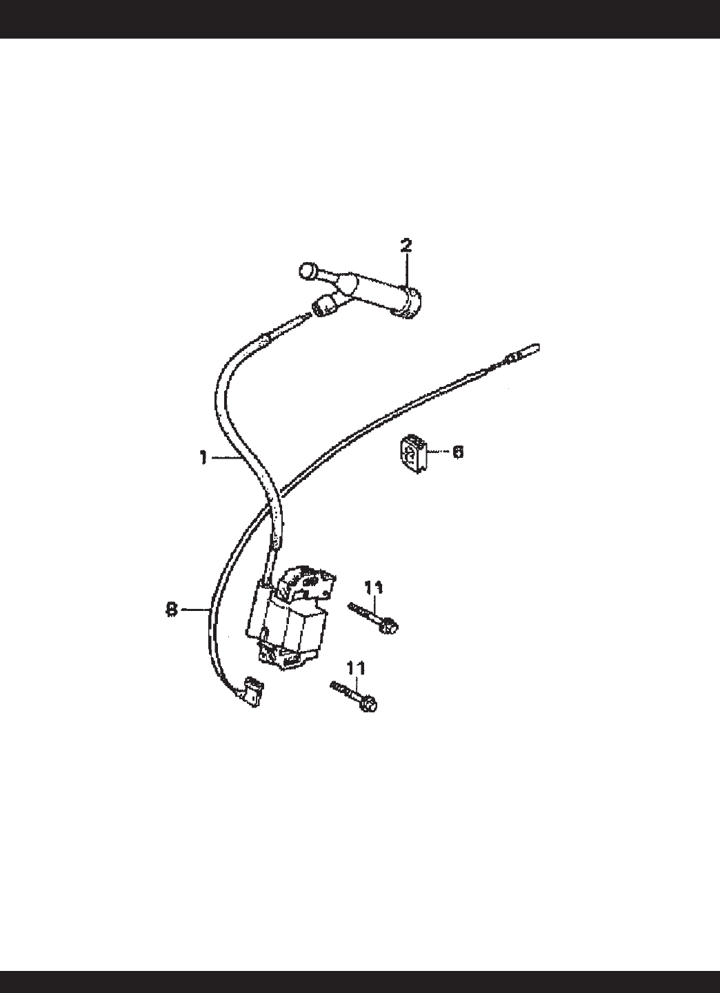
PAGE 72 — STOW CMS-9S CONCRETE MIXERS — PARTS & OPERATION MANUAL — REV. #6 (01/08/07)
HONDA GX240K1HA2ENGINE — IGNITION ASSY.
IGNITION COIL ASSY.

STOW CMS-9S CONCRETE MIXER — PARTS & OPERATION MANUAL — REV. #6 (01/08/07) — PAGE 73
HONDA GX240K1HA2ENGINE — IGNITION ASSY.
IGNITION COIL ASSY.
NO. PART NO. PART NAME QTY.REMARKS
1 30500ZF6W02 COIL ASSY., IGNITION 1
2 30700ZE1013 CAP ASSY., NOISE SUPPRESSOR 1
6 31512ZE2000 GROMMET, WIRE 1
8 36101ZE1010 WIRE, STOP SWITCH 370MM 1
11 90015883000 BOLT, FLANGE 6X28 2
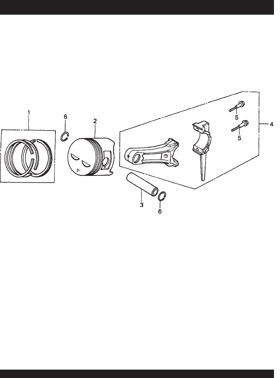
PAGE 74 — STOW CMS-9S CONCRETE MIXERS — PARTS & OPERATION MANUAL — REV. #6 (01/08/07)
HONDA GX240K1HA2 ENGINE — PISTON ASSY.
PISTON ASSY.

STOW CMS-9S CONCRETE MIXER — PARTS & OPERATION MANUAL — REV. #6 (01/08/07) — PAGE 75
HONDA GX240K1HA2 ENGINE — PISTON ASSY.
PISTON ASSY.
NO. PART NO. PART NAME QTY.REMARKS
1 13010ZE2013 RING SET, PISTON, STD. 1
1 13011ZE2013 RING SET, PISTON, OS 0.25, OPTIONAL 1
1 13012ZE2013 RING SET, PISTON, OS 0.50, OPTIONAL 1
1 13013ZE2013 RING SET, PISTON, 0.75, OPTIONAL 1
2 13101ZE2W00 PISTON, STANDARD 1
2 13102ZE2W00 PISTON, OS 0.25, OPTIONAL 1
2 13103ZE2W00 PISTON, OS 0.50, OPTIONAL 1
2 13104ZE2W00 PISTON, 0.75, OPTIONAL 1
3 13111ZE2000 PIN, PISTON 1
4 13200ZE2000 ROD ASSY., CONNECTING STANDARD ................ 1 .......... INCLUDES ITEMS W/*
4 13200ZE2305 ROD ASSY., CONNECTING, US 0.25, OPT. 1
5*90001ZE8000 BOLT, CONNECTING ROD 2
6 90551ZE1000 CLIP, PISTON PIN 18MM 2
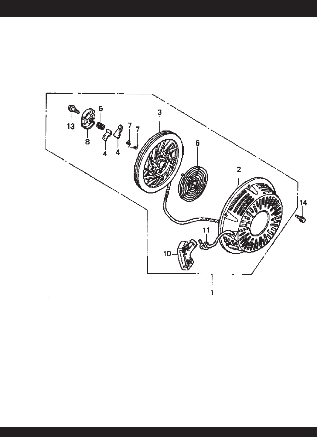
PAGE 76 — STOW CMS-9S CONCRETE MIXERS — PARTS & OPERATION MANUAL — REV. #6 (01/08/07)
HONDA GX240K1HA2 ENGINE — RECOIL STARTER ASSY.
RECOIL STARTER ASSY.

STOW CMS-9S CONCRETE MIXER — PARTS & OPERATION MANUAL — REV. #6 (01/08/07) — PAGE 77
HONDA GX240K1HA2 ENGINE — RECOIL STARTER ASSY.
RECOIL STARTER ASSY.
NO. PART NO. PART NAME QTY.REMARKS
1 28400ZE2W01ZB STARTER ASSY., RECOIL *NH1*, BLK ............... 1 ......... INCLUDES ITEMS W/*
2*28410ZE2W01ZB CASE COMP., RECOIL STARTER *NH1*, BLK 1
3*28421ZE2W01 PULLEY, RECOIL STARTER 1
4*28422ZE2W01 RATCHET, STARTER 2
5*28441ZE2W01 SPRING, FRICTION 1
6*28442ZE2W01 SPRING, STARTER RETURN 1
7*28443ZE2W01 SPRING RATCHET 2
8*28444ZE2W01 RETAINER, SPRING 1
10*28461ZE2W02 GRIP, STARTER 1
11*28462ZE2W11 ROPE, RECOIL STARTER 1
13*90004ZE2W01 SCREW, CENTER 1
14 90008ZE2003 BOLT, FLANGE 6X10 3
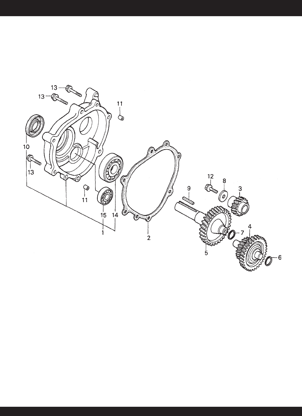
PAGE 78 — STOW CMS-9S CONCRETE MIXERS — PARTS & OPERATION MANUAL — REV. #6 (01/08/07)
HONDA GX240K1HA2 ENGINE — GEAR REDUCTION ASSY.
GEAR REDUCTION ASSY.

STOW CMS-9S CONCRETE MIXER — PARTS & OPERATION MANUAL — REV. #6 (01/08/07) — PAGE 79
HONDA GX240K1HA2 ENGINE — GEAR REDUCTION ASSY.
GEAR REDUCTION ASSY.
NO. PART NO. PART NAME QTY.REMARKS
1 11500ZE2620 COVER ASSY, REDUCTION CASE ............. 1 .......... INCLUDES ITEMS W/*
2 11521ZE2800 GASKET, CHAIN CASE COVER 1
3 22103ZE2620 GEAR, PRIMARY DRIVE (17T) 1
4 23220ZE2621 COUNTERSHAFT 1
5 23710ZE2621 SHAFT, P.T.O. (H- TYPE) 1
6 90401ZE2620 SHIM A (OPTIONAL) AR
7 90402ZE2620 SHIM B (OPTIONAL) AR
8 90473842000 WASHER (8MM) 1
9 90745ZE2600 KEY (6.3 X 6.3 X 43) 1
10*91201890003 OIL SEAL (30 X 46 X 8) 1
11 9430108140 PIN A, DOWEL ( 8 X 14) 2
12 957010802500 BOLT, FLANGE (8 X 25) 1
13 957010804000 BOLT, FLANGE (8 X 40) 6
14*961006206000 BEARING, RADIAL BALL (6206) 1
15*961006302000 BEARING, RADIAL BALL (6302) 1
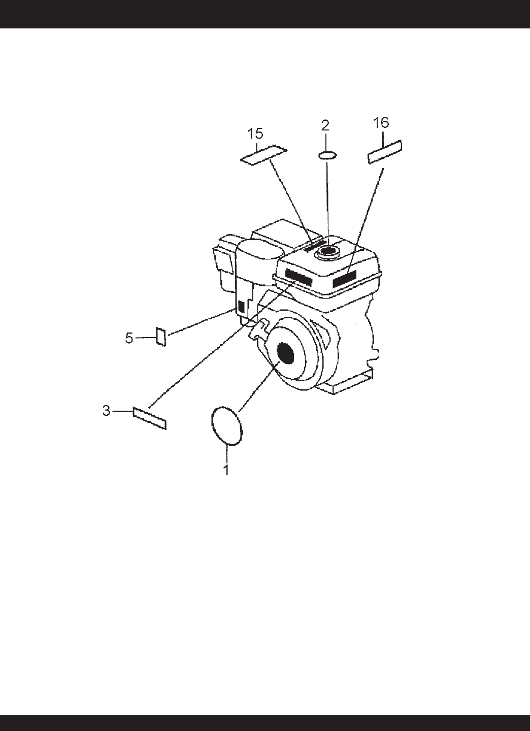
PAGE 80 — STOW CMS-9S CONCRETE MIXERS — PARTS & OPERATION MANUAL — REV. #6 (01/08/07)
HONDA GX240K1HA2 ENGINE — LABEL ASSY.
LABEL ASSY.

STOW CMS-9S CONCRETE MIXER — PARTS & OPERATION MANUAL — REV. #6 (01/08/07) — PAGE 81
HONDA GX240K1HA2 ENGINE — LABEL ASSY.
LABELS ASSY.
NO. PART NO. PART NAME QTY.REMARKS
1 87521ZE2W01 EMBLEM, INTERNAL 1
2 87522ZE1810 MARK, CAUTION, EXTERNAL 1
3 87522ZH9000 LABEL, CAUTION 1
5 87528ZE2810 MARK, CHOKE, EXTERNAL 1
15 87586ZH7W00 LABEL, FUEL CAUTION 1
16 87532ZH8810 MARK, OIL ALERT 1

PAGE 82 — STOW CMS-9S CONCRETE MIXERS — PARTS & OPERATION MANUAL — REV. #6 (01/08/07)
Effective: July 15, 2003 TERMS AND CONDITIONS OF SALE — PARTS
Terms and Conditions of Sale
STOW Construction Equipment
STOW CONSTRUCTION EQUIPMENT
POST OFFICE BOX 6254
CARSON, CALIFORNIA 90749
310-661-4242 • 877-BUY-STOW
FAX: 310-604-9237
E-MAIL: stow@stowmfg.com
www.stowmfg.com
Atlanta • Boise • Newark • Quebec, Canada
Manchester, UK • Rio de Janeiro, BR • Puebla, MX
PAYMENT TERMS
Terms of payment for unit sales are 2% 15 days
net 30 days from date of invoice unless
otherwise specifically stated on our invoice. Parts
invoices have terms of net 10 days. Minimum
parts billing is $15.00 net.
Applicable discounts will be computed on
merchandise value only. Late charges will be
assessed at prevailing rates. Cash discounts
cannot be taken on current billings if any
previously billed amounts are past due.
FREIGHT POLICY
Freight policy is established to offer customers
every advantage possible. Due to bulk freight
ratings on some equipment and other shipping
considerations, freight policies differ by
equipment type. Actual back freight may be
charged for shipments originating from other
than specified FOB warehouses. See Freight
Policy for details.
All STOW domestic sales are FOB nearest
available designated MQ/STOW warehouse.
Export orders are ex-works factory located in
Carson, CA or Boise, ID.
Additions to orders already shipped cannot be
accepted for freight minimums.
Should STOW elect to make partial shipments
of an order originally complying with the “freight
allowed” requirements, transportation charges
will be absorbed by STOW on any subsequent
shipment applying to that order.
All other orders will be shipped collect or prepaid
with charges added to the invoice. STOW’s
responsibility ceases when a signed manifest
has been obtained from the carrier, and any
claim for shortage or damage must be settled
between the consignee and the carrier.
Parts: FOB Carson, California or Boise, Idaho.
See Freight Policy for details and
additional discounts.
DROP SHIPMENTS
STOW reserves the right to refuse Drop
Shipments outside the normal service area of
the purchasing dealer.
FIELD WAREHOUSES
Field Warehouses are currently located in
California, Georgia, Idaho, Iowa, and New
Jersey
SPECIAL EXPEDITING SERVICE
The higher of a $35.00 surcharge or actual costs
will be added to the invoice for special handling,
including bus shipments, or in cases where
STOW personnel must personally deliver the
equipment or parts to the carrier.
RETURNED GOODS POLICY
Return shipments may be accepted and credit
allowed, subject to the following provisions.
1. A Returned Material Authorization (RMA)
must be approved by STOW prior to
shipment. Approvals for returned goods must
be with just cause and are at the
sole discretion of STOW. A copy of the
Authorization must accompany the shipment
to the designated Warehouse.
2. Parts being returned must be listed as
currently supplied on the current parts list.
3. Parts must be in new and resalable condition
in the original package, with part numbers
clearly marked.
4. Units and accessories must be current
models in the latest price list and in new and
resalable condition.
5. Special order items are not returnable for
credit.
6. Credit on returned parts and units will be
issued at actual dealer net price at time of
purchase less 15% restocking charge.
7. All returned shipments are to be made to the
STOW designated receiving point, freight
prepaid at the sender’s expense.
The sender will be notified of any material
received that does not meet the above provisions.
Such material will be held for 30 days from
notification pending instructions. If a reply is not
received within 30 days, the material will be
returned to the sender at his expense with no
credit issued.
PRICING, REBATES AND
SPECIFICATIONS
Every effort will be made to provide adequate
notice of changes; however, prices and
equipment specifications are subject to change
without notice.
Price changes are effective on a specific date
and all orders received on or after that date will
be billed at the revised price.
Rebates for price reductions and added charges
for price increases will not be made for stock in
dealer inventory at the time of a price change.
STOW reserves the right to quote and sell direct
to Government agencies and to Original
Equipment Manufacturer accounts who use our
products as integral parts of their own products.
LIMITATION OF SELLER’S LIABILITY
STOW shall not be liable hereunder for damages
in excess of the purchase price of the item with
respect to which damages are claimed and in
no event shall STOW be liable for loss of profit
or good will or for any other special, consequential
or incidental damages.
LIMITATION OF WARRANTIES
There are no warranties, express or implied,
made by STOW. hereunder on Products
manufactured or distributed by it except the
warranty against defects in material and
workmanship on new Products to the original
purchaser, as set forth in the STOW New Product
Limited Warranty.

STOW CMS-9S CONCRETE MIXER — PARTS & OPERATION MANUAL — REV. #6 (01/08/07) — PAGE 83
NOTE PAGE

OPERATION AND PARTS MANUAL
PARTS DEPARTMENT:
800-427-1244
FAX: 800-672-7877
SERVICE DEPARTMENT/TECHNICAL ASSISTANCE:
800-478-1244
FAX: 310-631-5032
STOW CONSTRUCTION EQUIPMENT
A DIVISION OF MULTIQUIP INC.
POST OFFICE BOX 6254
CARSON, CA 90749
310-537-3700 • 888-252-STOW [888-252-7869]
FAX: 310-537-1986 • FAX: 800-556-1986
E-MAIL: STOW@multiquip.com • WWW: stowmfg.com
HERE'S HOW TO GET HELP
PLEASE HAVE THE MODEL AND SERIAL
NUMBER
ON-HAND
WHEN CALLING
PARTS DEPARTMENT
800-427-1244 FAX: 800-672-7877
310-537-3700 FAX: 310-637-3284
SERVICE DEPARTMENT
800-478-1244 FAX: 310-537-4259
310-537-3700
TECHNICAL ASSISTANCE
800-478-1244 FAX: 310-631-5032
WARRANTY DEPARTMENT
800-421-1244, EXT. 279 FAX: 310-537-1173
310-537-3700, EXT. 279
SALES DEPARTMENT
310-661-4242 FAX: 310-604-9237
877-289-7869 (877-BUY-STOW)
