Stow Vehicle T 20H Users Manual REV 0.p65
T-20H to the manual 62996484-805a-48dd-a34c-5639252b3c30
2015-02-02
: Stow Stow--Vehicle-T-20H-Users-Manual-489446 stow--vehicle-t-20h-users-manual-489446 stow pdf
Open the PDF directly: View PDF ![]() .
.
Page Count: 70

OPERATION AND PARTS MANUAL
© COPYRIGHT 2003, MULTIQUIP INC.
MODEL T-20H
TRASH PUMP
PARTS DEPARTMENT:
800-427-1244
FAX: 800-672-7877
SERVICE DEPARTMENT/TECHNICAL ASSISTANCE:
800-478-1244
FAX: 310-631-5032
STOW CONSTRUCTION EQUIPMENTSTOW CONSTRUCTION EQUIPMENT
STOW CONSTRUCTION EQUIPMENTSTOW CONSTRUCTION EQUIPMENT
STOW CONSTRUCTION EQUIPMENT
A DIVISION OF MULTIQUIP INC.
POST OFFICE BOX 6254
CARSON, CA 90749
310-537-3700 • 888-252-STOW [888-252-7869]
FAX: 310-537-1986 • FAX: 800-556-1986
E-MAIL: stow@multiquip.com • WWW: stowmfg.com
Revision #0 (05/29/03)
PAGE 2 —STOW T-20H TRASH PUMP — PARTS MANUAL — REV. #0 (05/29/03)

STOW T-20H TRASH PUMP — PARTS MANUAL— REV. #0 (05/29/03) — PAGE 3
HERE'S HOW TO GET
HELP
PLEASE HAVE THE MODEL AND SERIAL
NUMBER ON-HAND WHEN CALLING
PARTS DEPARTMENT
800-427-1244 or 310-537-3700
FAX: 800-672-7877 or 310-637-3284
SERVICE DEPARTMENT
800-421-1244
FAX: 310- 537-4259
TECHNICAL ASSISTANCE
800-478-1244
FAX: 310- 631-5032
WARRANTY DEPARTMENT
888-661-4279, or 310-661-4279
FAX: 310- 537-1173

PAGE 4 —STOW T-20H TRASH PUMP — PARTS MANUAL — REV. #0 (05/29/03)
Specification and part number
are subject to change without
notice.
NOTE
STOW T-20H Gasoline
Powered Trash Pump
Here’s How To Get Help ............................................ 2
Table of Contents ...................................................... 3
Parts Ordering Procedures .................................... 4-5
Safety Message Alert Symbols .............................. 6-7
Rules For Safe Operation ...................................... 8-9
Pump Specifications/Dimensions .............................10
Engine Specifications ...............................................11
General Information .................................................12
Pump Components ..................................................13
Basic Engine ............................................................14
Pre-Inspection (Engine) ...........................................15
Pre-Set-up (Pump) ...................................................16
Initial Start-up (Engine) ...................................... 17-18
Maintenance (Pump) ......................................... 20-21
Maintenance (Engine)........................................ 22-23
Preparation for Long-Term Storage .........................24
Troubleshooting (Pump)...........................................26
Troubleshooting (Pump/Engine) ..............................27
Explanation Of Code In Remarks Column ...............28
Suggested Spare Parts ............................................29
Pump Assy. ........................................................ 30-33
HondaGX160K1TX2 Engine
Air Cleaner (Dual) Assembly .............................. 34-35
Camshaft Assembly ........................................... 36-37
Carburetor Assembly ......................................... 38-39
Control Assembly ............................................... 40-41
Crankcase Cover Assembly ............................... 42-43
Crankshaft Assembly ......................................... 44-45
Cylinder Barrel Assembly ................................... 46-47
Cylinder Head Assembly .................................... 48-49
Fan Cover Assembly .......................................... 50-51
Flywheel Assembly ............................................ 52-53
Fuel Tank Assembly ........................................... 54-55
Ignition Coil Assembly ........................................ 56-57
Muffler Assembly ............................................... 58-59
Piston Assembly ................................................. 60-61
Recoil Starter Assembly..................................... 62-63
Gasket Kit Assembly ............................................... 65
Labels ................................................................ 66-67
Terms and Condition Of Sale — Parts .................... 68
STOW T-20H — TABLE OF CONTENTS
STOW T-20H TRASH PUMP — PARTS MANUAL— REV. #0 (05/29/03) — PAGE 5
PARTS ORDERING PROCEDURES
When ordering parts,
please supply the following information:
❒❒
❒❒
❒Dealer account number
❒❒
❒❒
❒Dealer name and address
❒❒
❒❒
❒Shipping address (if different than billing address)
❒❒
❒❒
❒Return fax number
❒❒
❒❒
❒Applicable model number
❒❒
❒❒
❒Quantity, part number and description of each part
❒❒
❒❒
❒Specify preferred method of shipment:
✓FedEx or UPS Ground
✓FedEx or UPS Second Day or Third Day
✓FedEx or UPS Next Day
✓Federal Express Priority One
✓DHL
✓Tr u ck
Here’s how to get help...
Please have the model and serial number on
hand when calling.
Parts Department
800-427-1244 Fax: 800-672-7877
310-537-3700 Fax: 310-637-3284
Mayco Parts
800-306-2926 Fax: 800-672-7877
310-537-3700 Fax: 310-637-3284
Service Department
800-478-1244 Fax: 310-537-4259
310-537-3700
MQ Power Service Department
800-835-2551 Fax: 310-638-8046
310-537-3700
Warranty Department
800-421-1244, Ext. 279 Fax: 310-537-1173
310-537-3700, Ext. 279
Multiquip’s Main Phone Numbers
800-421-1244 Fax: 310-537-3927
310-537-3700
Note: Unless otherwise indicated by customer, all
orders are treated as “Standard Orders”, and will
ship within 24 hours. We will make every effort to
ship “Air Shipments” the same day that the order is
received, if prior to 2PM west coast time. “Stock
Orders” must be so noted on fax or web forms.
Extra Discounts!
All parts orders which include complete part numbers
and are received by our automated web parts order
system, or by fax qualify for the following extra
discounts:
Ordered Standard Stock orders
via orders ($750 list and above)
Fax 3% 10%
Web 5% 10%
Special freight allowances
when you order 10 or more
line items via Web or Fax!**
FedEx Ground Service
at no charge for freight
No other allowances on freight shipped by any other
carrier.
Place Your Parts Order Via Web or Fax
For Even More Savings!
NOTE: DISCOUNTS ARE SUBJECT TO CHANGE
MULTIQUIP INC.
18910 WILMINGTON AVENUE
POST OFFICE BOX 6254
CARSON, CALIFORNIA 90749
310-537-3700 • 800-421-1244
FAX: 310-537-3927
E-MAIL: mq@multiquip.com
WWW: multiquip.com
Direct TOLL-FREE access
to our Parts Department:
Toll-free nationwide — 800-427-1244
PAGE 6 —STOW T-20H TRASH PUMP — PARTS MANUAL — REV. #0 (05/29/03)
STOW T-20H — SAFETY MESSAGE ALERT SYMBOLS
Safety precautions should be followed at all times when operating
this equipment. Failure to read and understand the Safety
Messages and Operating Instructions could result in injury to
yourself and others.
FOR YOUR SAFETY AND THE SAFETY OF OTHERS!
This Owner's Manual has been
developed to provide complete
instructions for the safe and efficient
operation of the
STOW
Model T-20H
Trash Pump.
Refer to the engine
manufacturers instructions for data
relative to its safe operation.
Before using these pumps,
ensure that the operating
individual has read and
understands all instructions in
this manual.
SAFETY MESSAGE ALERT SYMBOLS
The three (3) Safety Messages shown below will inform you
about potential hazards that could injure you or others. The
Safety Messages specifically address the level of exposure to
the operator, and are preceded by one of three words: DANGER,
WARNING, or CAUTION.
DANGER: You WILL be KILLED or
SERIOUSLY injured if you do not follow
WARNING: You CAN be KILLED or
SERIOUSLY injured if you do not follow
directions.
CAUTION: You CAN be injured if you
do not follow directions.
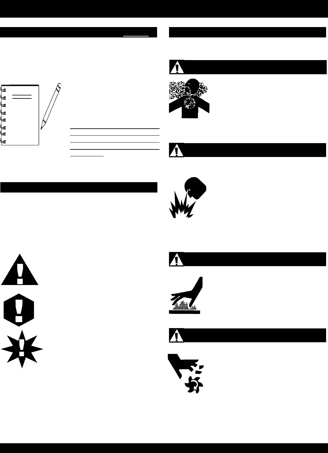
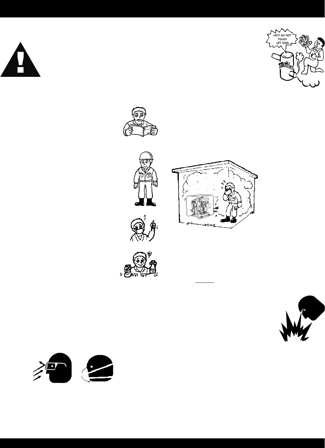
HAZARD SYMBOLS
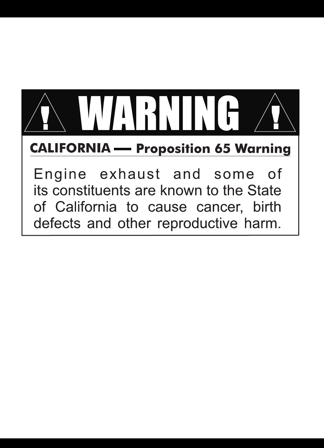
Engine exhaust gases contain poisonous
carbon monoxide. This gas is colorless and
odorless, and can cause death if inhaled.
NEVER operate this equipment in a confined
area or enclosed structure that does not
provide ample free flow air.
Potential hazards associated with the STOW T-20H Trash Pump
operation will be referenced with Hazard Symbols which appear
throughout this manual, and will be referenced in conjunction
with Safety Message Alert Symbols.
GASOLINE is extremely flammable, and its
vapors can cause an explosion if ignited. DO
NOT start the engine near spilled fuel or
combustible fluids. DO NOT fill the fuel tank
while the engine is running or hot. DO NOT
overfill tank, since spilled fuel could ignite if it
comes into contact with hot engine parts or
sparks from the ignition system. Store fuel in
approved containers, in well-ventilated areas
and away from sparks and flames. NEVER
Explosive Fuel
Lethal Exhaust Gases
Burn Hazards
Engine components can generate extreme heat.
To prevent burns, DO NOT touch these areas
while the engine is running or immediately after
operations. Never operate the engine with heat
shields or heat guards removed.
Rotating Parts
NEVER operate equipment with covers, or
guards removed. Keep fingers, hands, hair and
clothing away from all moving parts to prevent
injury.
NOTE
STOW T-20H TRASH PUMP — PARTS MANUAL— REV. #0 (05/29/03) — PAGE 7
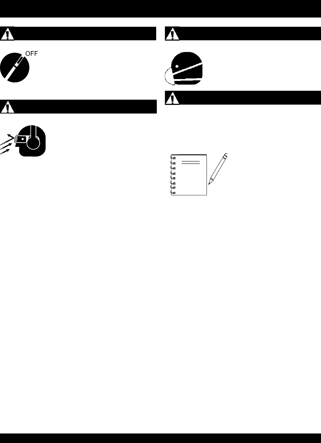
Accidental Starting
STOW T-20H — SAFETY MESSAGE ALERT SYMBOLS
ALWAYS place the engine ON/OFF switch in
the OFF position when the pump is not in use.
Respiratory Hazard
ALWAYS wear approved respiratory
protection.
Equipment Damage Messages
Other important messages are provided throughout this manual
to help prevent damage to your pump, other property, or the
surrounding environment.
ALWAYS wear approved eye and hearing
protection.
Sight and Hearing hazard
This pump, other property, or the
surrounding environment could be
damaged if you do not follow
instructions.
NOTE
PAGE 8 —STOW T-20H TRASH PUMP — PARTS MANUAL — REV. #0 (05/29/03)
RULES FOR SAFE OPERATION
■
ALWAYS refuel in a well-ventilated area, away from sparks
and open flames.
■
ALWAYS use extreme caution when working with flammable
liquids. When refueling, stop the engine and allow it to cool.
DO NOT smoke around or near the machine. Fire or explosion
could result from fuel vapors, or if fuel is spilled on a hot
engine.
■
NEVER operate the pump in an
explosive
atmosphere
or near combustible
materials. An explosion or fire could result
causing severe
bodily harm or even
death.
■
Topping-off to filler port is dangerous, as it tends to spill fuel.
■
Refer to the
Engine Owner's Manual
for engine technical
questions or information.
■
NEVER use accessories or attachments, which are not
recommended by Multiquip for this equipment. Damage to
the equipment and/or injury to user may result.
■
Manufacturer does not assume responsibility for any accident
due to equipment modifications.
■
NEVER touch the hot exhaust manifold,
muffler or cylinder. Allow these parts to
cool before servicing engine or pump.
■
The engine of this pump requires an adequate free flow of
cooling air.
NEVER!
operate the pump in any enclosed or
narrow area where free flow of the air is restricted. If the air
flow is restricted it will
cause serious damage
to the pump or engine
and may cause injury to
people and property.
Remember the pump's
engine gives off
DEADLY gases.
■
High Temperatures – Allow the engine to cool before adding
fuel or performing service and maintenance functions. Contact
with
hot!
components can cause serious burns.
The following safety guidelines should always be used when
operating the
trash pump
:
GENERAL SAFETY
■
DO NOT operate or service this equipment before
reading this entire manual.
■
This equipment should not be operated by
persons under 18 years of age.
■
NEVER operate this equipment without proper
protective clothing, shatterproof glasses, steel-
toed boots and other protective devices required
by the job.
■
NEVER operate this equipment when not feeling
well due to fatigue, illness or taking medicine.
■
NEVER operate this equipment under the
influence or drugs or alcohol.
■
Whenever necessary, replace nameplate, operation and safety
decals when they become difficult read.
■
ALWAYS check the machine for loosened threads or bolts
before starting.
■
ALWAYS wear proper respiratory (mask) hearing and eye
protection equipment when operating the pump.
DANGER:
Failure to follow instructions in this manual may
lead to serious injury or even death! This
equipment is to be operated by trained and
qualified personnel only! This equipment is for
industrial use only.
STOW T-20H TRASH PUMP — PARTS MANUAL— REV. #0 (05/29/03) — PAGE 9
■
High Temperatures – Always stop engine and allow the
engine to cool before adding fuel, oil or performing service
and maintenance functions. Contact with
hot
components can
cause serious burns.
■
NEVER disconnect any
"emergency or safety devices"
.
These devices are intended for operator safety. Disconnection
of these devices can cause severe injury, bodily harm or even
death! Disconnection of any of these devices will void all
warranties.
Maintenance Safety
■
NEVER lubricate components or attempt service on a running
machine.
■
ALWAYS allow the machine a proper amount of time to cool
before servicing.
■
Keep the machinery in proper running condition.
■
Fix damage to the machine immediately and always replace
broken parts, or missing decals.
■
Dispose of hazardous waste properly. Examples of potentially
hazardous waste are used motor oil, fuel and fuel filters.
■
DO NOT use food or plastic containers to dispose of
hazardous waste.
■
DO NOT pour waste, oil or fuel directly onto the ground,
down a drain or into any water source.
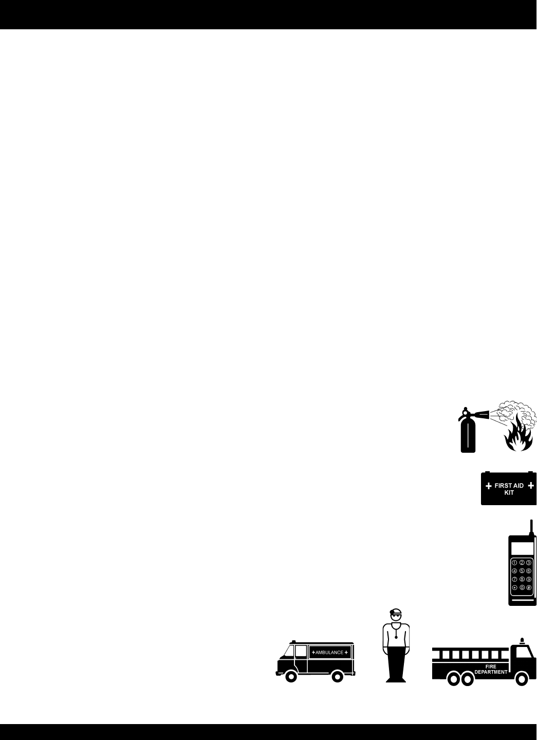
Emergencies
■
ALWAYS know the location of the
nearest
fire extinguisher
.
■
ALWAYS know the location of the nearest
first aid kit
.
■
In emergencies
always
know the location of the
nearest phone or
keep a phone on the job site
.
Also know the phone numbers of the nearest
ambulance
,
doctor
and
fire department
. This
information will be invaluable in the case of an
emergency.
■
NEVER Run engine without air cleaner. Severe engine
damage may occur.
■
ALWAYS read, understand, and follow procedures in
Operator’s Manual before attempting to operate equipment.
■
ALWAYS be sure the operator is familiar with proper safety
precautions and operation techniques before using pump.
■
ALWAYS store equipment properly when it is not being used.
Equipment should be stored in a clean, dry location out of the
reach of children.
■
NEVER leave the pump unattended, turn off engine when
unattended.
■
Unauthorized equipment modifications will void all
warranties.
■
NEVER pump volatile, explosive, flammable or low flash point
fluids. These fluids could ignite or explode.
■
NEVER operate the pump in an
explosive
atmosphere.
■
Before starting the pump, check that the clean-out cover is
securely fasten.
■
ALWAYS ensure pump is on level ground before use.
■
Become familiar with the components of the pump before
operating.
■
ALWAYS replace any worn or damaged warning decals.
■
NEVER pump corrosive chemicals or water containing toxic
substances. These fluids could create serious health and
environmental hazards. Contact local authorities for
assistance.
■
NEVER open the priming plug when pump is hot. Hot water
inside could be pressurized much like the radiator of an
automobile. Allow pump to cool to the touch before loosening
plug.
■
NEVER open the pump housing during operation or start the
pump with the clean-out cover removed. The rotating impeller
inside the pump can cut or sever objects caught in it.
■
NEVER block or restrict flow from discharge hose. Remove
kinks from discharge line before starting pump. Operation
with a blocked discharge line can cause water inside pump
to overheat.
■
ALWAYS fill the pump casing with water before starting the
engine. Failure to maintain water inside the pump housing
will cause severe damage to the pump.
■
In winter drain water from pump housing to prevent freezing.
RULES FOR SAFE OPERATION
PAGE 10 —STOW T-20H TRASH PUMP — PARTS MANUAL — REV. #0 (05/29/03)
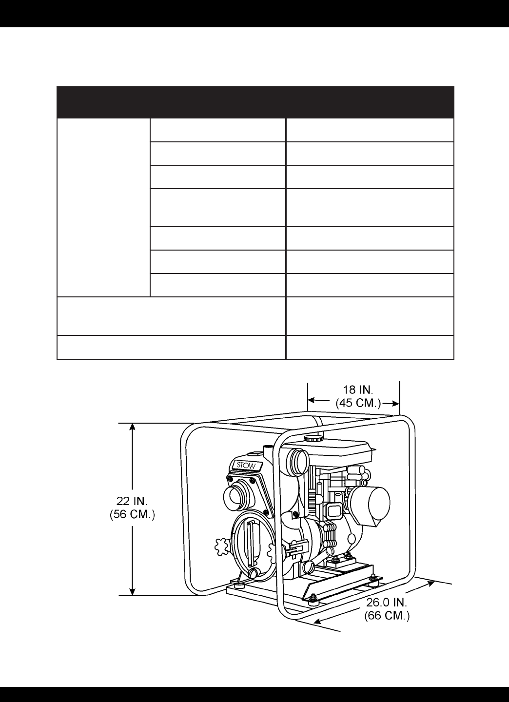
STOW T-20H — SPECIFICATIONS/DIMENSIONS (PUMP)
Figure 1. T-20H Dimensions
)pmuP(snoitacificepS.1elbaT
pmuP
ledoMH02-T
epyTpmuPhsarT
eziSegrahcsiD&noitcuS).mm15(.ni00.2
gnipmuPmumixaM
yticapaC
etunim/snollag851
)etunim/sretil895(
retemaiDsdiloS.xaM).mm52(.ni00.1
tfiL.xaM)sretem26.7(.tf52
daeH.xaM)sretem42(.tf97
noisnemiD
)HxWxL(
.ni0.22X0.81x0.62
).mc65X54X66(
thgieWteNyrD ).gK25(.sbl511
STOW T-20H TRASH PUMP — PARTS MANUAL— REV. #0 (05/29/03) — PAGE 11
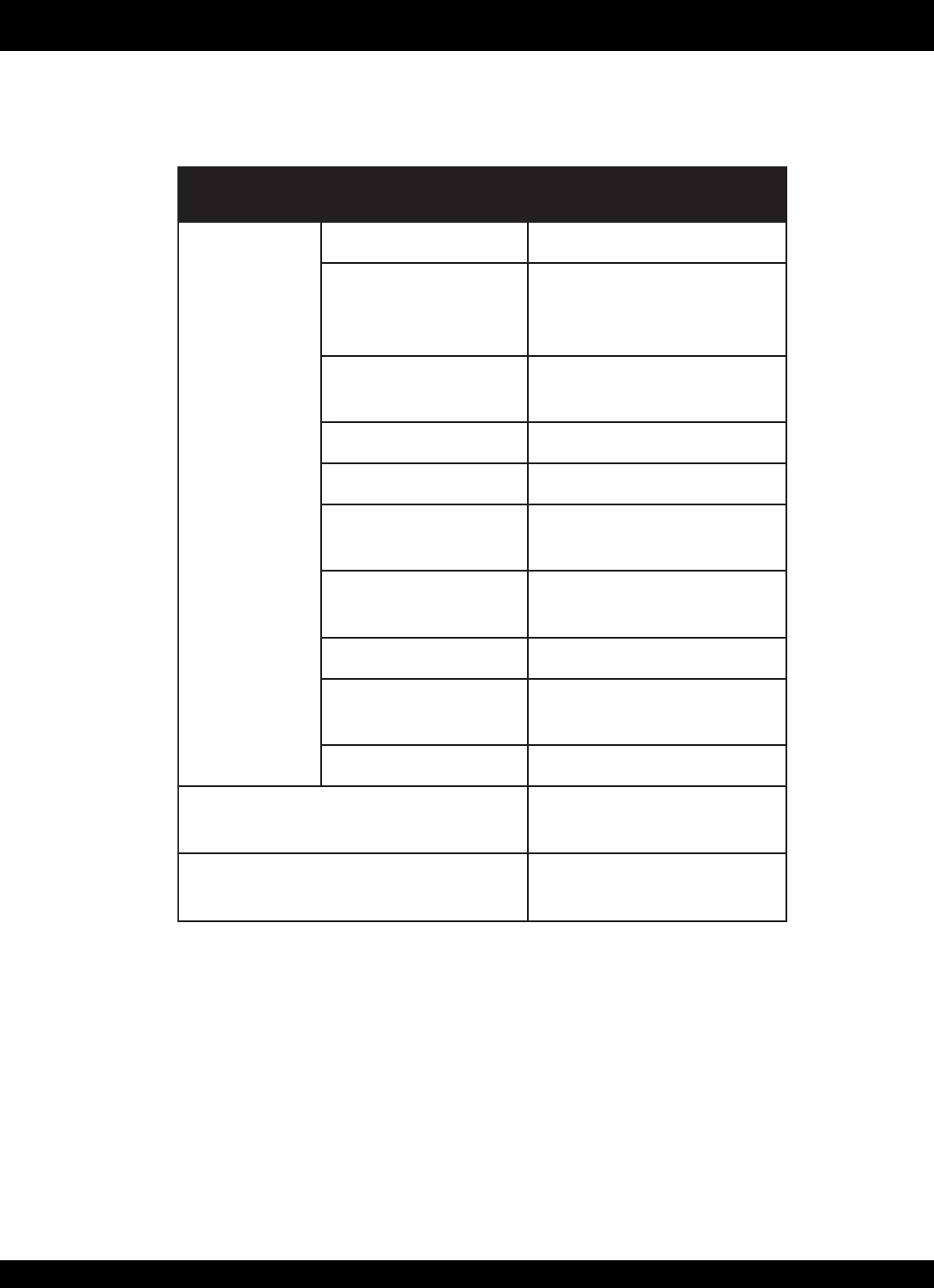
STOW T-20H — SPECIFICATIONS/DIMENSIONS (ENGINE)
)enignE(snoitacificepS.2elbaT
enignE
ledoM2XT1K061XGADNOH
epyT
elgniS,ekorts4delooc-riA
latnoziroH,VHO,rednilyC
enignEenilosaGtfahS
ekortSXeroB .ni8.1x.ni7.2
)mm54xmm86(
tnemecalpsiD)ni-uc9.9(cc361
tuptuOxaM.M.P.R0063/.P.H5.5
yticapaCknaTleuF snollag.S.U59.0.xorppA
)sretil6.3(
leuF elibomotuAdedaelnU
enilosaG
yticapaCliOebuL)stq36.0(sretil06.
lortnoCdeepS
dohteM epyTthgiew-ylFlagufirtneC
dohteMgnitratStratSlioceR
noisnemiD
)HxWxL(
.ni2.31x4.41x0.21
)mm533x263x403(
yrD
thgieWteN ).gK51(sbl1.33
PAGE 12 —STOW T-20H TRASH PUMP — PARTS MANUAL — REV. #0 (05/29/03)
STOW T-20H — GENERAL INFORMATION
APPLICATION
The
STOW Model T-20H Trash Pump
is designed to be used
for de-watering applications. Both the suction and discharge
ports on the T-20H pump use a 2-inch diameter opening, which
allows the pump to pump at a rate of approximately 158 gallons/
minute (gpm) or 598 liters/minute (lpm).
Trash or self priming pumps are designed to purge air from the
suction line and create a partial vacuum in the pump body. The
reduced atmospheric pressure inside the pump allows water to
flow through the suction line and into the pump body. The
centrifugal force created by the rotating impeller pressurizes the
water and expels it from the pump.
Power Plant
This trash pump is powered by an 5.5 horsepower air cooled 4-
stroke, single cylinder
HONDA GX-160
gasoline engine that
incorporates a low "
Oil Alert Feature
"
Oil Alert Feature
In the event of
low oil
or
no oil
, the HONDA GX-160 engine has
a built-in oil alarm engine shut-down feature. In the event the oil
level is low the engine will automatically shut-down.
Trash Pump
Trash pumps derive their name from their ability to handle a
greater amount of debris and solids than standard centrifugal
pumps. These pumps generally handle solids up to 1/2 the size
of the discharge opening making them less likely to clog. Also
trash pumps are capable of handling water with 25% solids by
weight.
The advantage of using a trash pump is that it can be quickly and
easily disassembled in the field "
without tools
" and easily
cleaned when clogged.
Suction Lift
This pump is intended to be used for dewatering applications
and is capable of suction lifts up to 25 feet at sea level. For
optimal suction lift performance keep the suction hose or line as
short as possible. In general always place the pump as close to
the water as possible.
Pump Support
The pump should always be placed on
solid stationary ground
in a level position.
NEVER place the pump on
soft soil
. The suction hose or pipe
connection should always be checked for tightness and leaks. A
small suction leak in the hose or fittings could prevent the pump
from priming.
Elevation
Higher elevations will effect the performance of the pump. Due to
less atmospheric pressure at higher altitudes, pumps DO NOT
have the priming ability that they have at sea level. This is due to
the “thinner air” or lack of oxygen at higher altitudes.
A general rule of thumb is that for every 1,000 feet of elevation
above sea level a pump will lose one foot of priming ability.
For example, in Flagstaff, Arizona where the elevation is
approximately 7,000 feet, the pump would have a suction lift of
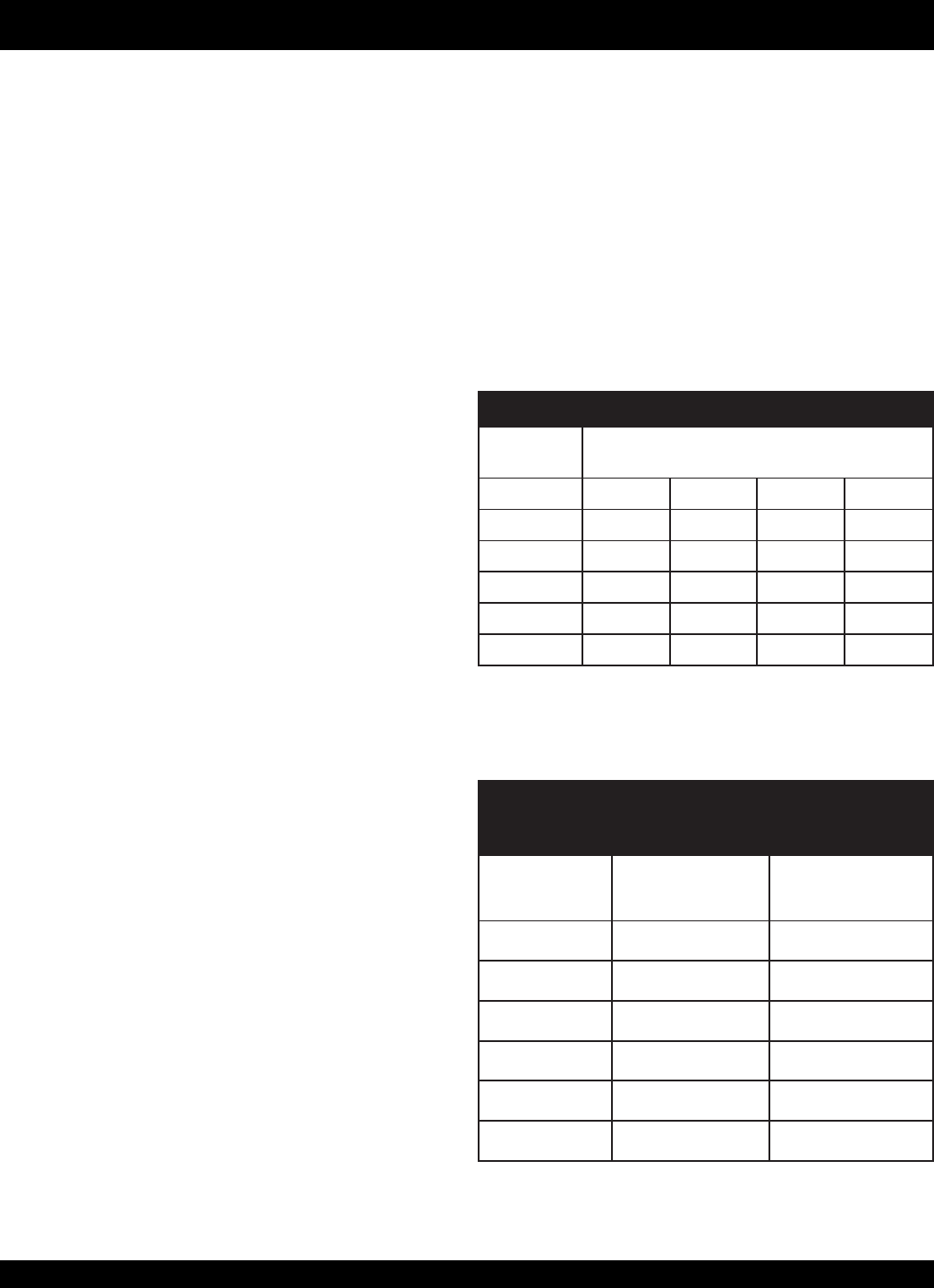
only 18 feet rather than the 25 feet at sea level. Table 3 shows
suction lift at various elevations.
Table 4 shows percentage drops in performance as elevation
increases.
snoitavelEsuoiraVtatfiLnoitcuS.3elbaT
edutitlA
)sreteM(teeF )sreteM(teeFnitfiLnoitcuS
leveLaeS)840.3(0.01)275.4(0.51)690.6(0.02)026.7(0.52
)016(000,2)086.2(08.8)320.4(2.31)463.5(6.71)507.6(0.22
)912,1(000,4)773.2(08.7)665.3(7.11)457.4(6.51)349.5(5.91
)928,1(000,6)301.2(09.6)961.3(4.01)602.4(8.31)372.5(3.71
)834,2(000,8)988.1(02.6)438.2(03.9)977.3(4.21)427.4(5.51
)840,3(000,01)737.1(07.5)126.2(06.8)474.3(4.11)853.4(3.41
suoiraVtassoLecnamrofreP.4elbaT
snoitavelE
edutitlA
sreteM(teeF wolFegrahcsiDdaeHegrahcsiD
leveLaeS%001%001
)016(000,2%79%59
)912,1(000,4%59%19
)928,1(000,6%39%78
)834,2(000,8%19%38
)840,3(000,01%88%87
STOW T-20H TRASH PUMP — PARTS MANUAL— REV. #0 (05/29/03) — PAGE 13
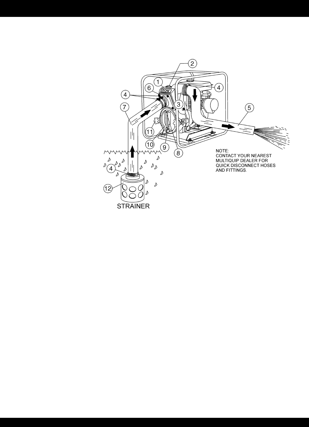
Figure 2 shows a typical application using the STOW T-20H trash pump. Please note that this pump is intended for the removal of
clean water and water containing some debris and solids. Maximum size of solids should not exceed 1 inch (25 mm) in diameter. DO
NOT set strainer on bottom of water bed. Placing the strainer above the water bed will prevent the pump from drawing in excessive
amounts of sand and foreign debris.
1. Pump – The STOW Model T-20H is 2-inch trash pump
used in general de-watering applications. Typical
dewatering applications consist of manholes, septic tanks,
fast and slow seepage ditch water, silt water, mud water
and muck water.
2. Fill Cap – Prior to operation, the pump casing should be
filled with water. Remove this cap to add water to the pump.
After the initial prime, a sufficient amount of water will be
retained in the casing so that the operator will not need to
re-prime later.
If the casing is dry or has insufficient water, the pump will
have difficulty in priming which could lead to premature
mechanical seal wear thus causing damage to the pump.
3. Discharge Port – Connect a 2-inch discharge hose to this
port.
4. Worm Clamp – Used to secure the hose to the inlet and
outlet ports on the pump. Use two clamps to secure the
hose on the inlet side of the pump.
5. Discharge Hose – Connect this flexible rubber hose to
the discharge port on the pump. Make sure that the hose
lays flat and is not kinked. Use only recommended type
discharge hose. Contact Multiquip parts department for
ordering information.
6. Suction Port – Connect a 2-inch inlet hose to this port.
Use two worm clamps to secure the hose.
7. Suction Hose – Connect this flexible rubber hose to the
suction port on the pump. Make sure that the hose lays flat
and is not kinked. Use only recommended type suction
hose. Contact Multiquip parts department for ordering
information
8. Clean-out Cover Handles – To gain access to the pump's
clean-out area, grip both handles, then pull to remove cover.
Make sure both locking knobs have been released before
attempting to remove clean-out cover.
9. Drain Plug – Remove this plug to drain water from the
pump.
10. Clean-out Cover – Remove cover to gain access to the
clean-out area.
11. Locking Knobs– Turn both knobs clockwise to secure
clean-out cover, turn counter-clockwise to release cover.
12. Strainer – Always attach a strainer to bottom side of the
suction hose to prevent large objects and debris from
entering the pump. Strainer should be positioned so that it
will remain completely under water. Running the pump with
the strainer above water for long periods can damage pump.
Figure 2. STOW T-20H Pump Application
STOW T-20H — PUMP COMPONENTS
PAGE 14 —STOW T-20H TRASH PUMP — PARTS MANUAL — REV. #0 (05/29/03)
STOW T-20H — BASIC ENGINE
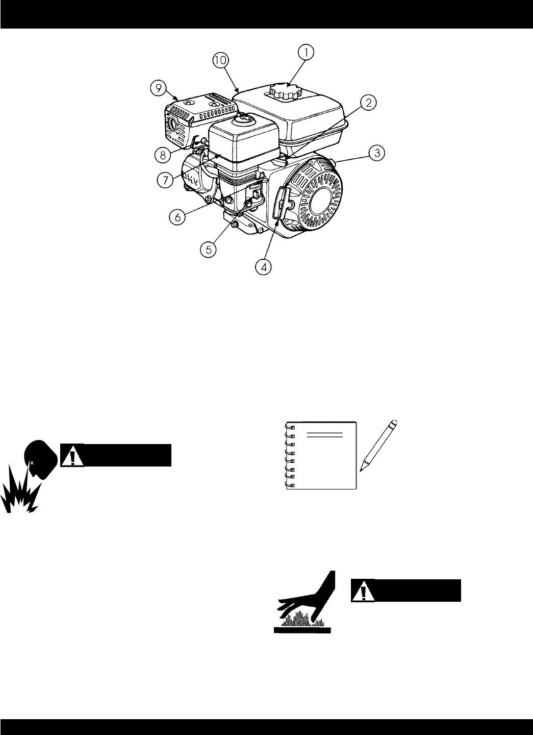
Figure 3. Engine Controls and Components
INITIAL SERVICING
The engine (Figure 3) must be checked for proper lubrication and
filled with fuel prior to operation. Refer to the manufacturers engine
manual for instructions & details of operation and servicing. The
engine shown above is a HONDA engine, operation for other
types of engines may vary somewhat.
1. Fuel Filler Cap – Remove this cap to add unleaded
gasoline to the fuel tank. Make sure cap is tightened
securely. DO NOT over fill.
6. Choke Lever – Used in the starting of a cold engine, or in
cold weather conditions. The choke enriches the fuel
mixture.
7. Air Cleaner – Prevents dirt and other debris from entering
the fuel system. Remove wing-nut on top of air filter
cannister to gain access to filter element.
8. Spark Plug – Provides spark to the ignition system. Set
spark plug gap to 0.6 - 0.7 mm (0.028 - 0.031 inch) Clean
spark plug once a week.
9. Muffler – Used to reduce noise and emissions.
Engine components can generate extreme heat.
To prevent burns, DO NOT touch these areas
while the engine is running or immediately after operating. NEVER
operate the engine with the muffler removed.
10. Fuel Tank – Holds unleaded gasoline. For additional
information refer to engine owner's manual.
DANGER
Operating the engine without an
air filter, with a damaged air filter,
or a filter in need of replacement
will allow dirt to enter the engine,
causing rapid engine wear.
WARNING
Adding fuel to the tank should be done only when
the engine is stopped and has had an opportunity to
cool down. In the event of a fuel spill, DO NOT attempt to start the
engine until the fuel residue has been completely wiped up, and the
area surrounding the engine is dry.
2. Throttle Lever – Used to adjust engine RPM speed (lever
advanced forward
SLOW
, lever back toward operator
FAST
).
3. Engine ON/OFF Switch – ON position permits engine
starting, OFF position stops engine operations.
4. Recoil Starter (pull rope) – Manual-starting method. Pull
the starter grip until resistance is felt, then pull briskly and
smoothly.
5. Fuel Valve Lever – OPEN to let fuel flow, CLOSE to stop
the flow of fuel.
NOTE
STOW T-20H TRASH PUMP — PARTS MANUAL— REV. #0 (05/29/03) — PAGE 15
STOW T-20H — PRE-INSPECTION (ENGINE)
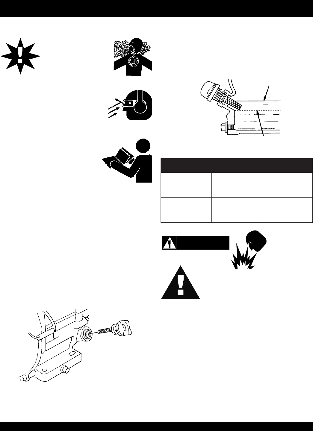
Figure 4. Engine Oil Dipstick (Removal)
3. Insert and remove the dipstick without screwing it into the filler
neck. Check the oil level shown on the dipstick.
4. If the oil level is low (Figure 5), fill to the edge of the oil filler
hole with the recommended oil type (Table 5). Maximum oil
capacity is 1.16 quarts (1.1 liters)
Figure 5. Engine Oil Dipstick (Oil Level)
Before Starting
1. Read safety instructions at the
beginning of manual.
2. Clean the pump, removing dirt and
dust, particularly the engine
cooling air inlet, carburetor and air
cleaner.
3. Check the air filter for dirt and dust. If air filter is dirty, replace
air filter with a new one as required.
4. Check carburetor for external dirt and dust. Clean with dry
compressed air.
5. Check fastening nuts and bolts for tightness.
Engine Oil Check
1. To check the engine oil level, place the pump on secure
level ground with the engine stopped.
2. Remove the filler dipstick from the engine oil filler hole
(Figure 4) and wipe clean.
CAUTIONCAUTION
CAUTIONCAUTION
CAUTION
NEVER operate the pump
in a confined area or
enclosed area structure that
does not provide ample
free
flow of air
.
ALWAYS wear approved eye and hearing
protection before operating the pump.
Fuel Check
1. Remove the gasoline cap located on top of fuel tank.
2. Visually inspect to see if the fuel level is low. If fuel is low,
replenish with unleaded fuel.
3. When refueling, be sure to use a strainer for filtration. DO
NOT top-off fuel. Wipe up any spilled fuel
immediately!
Explosive Fuel
DANGERDANGER
DANGERDANGER
DANGER
Motor fuels are highly flammable and can be
dangerous if mishandled. DO NOT smoke
while refueling. DO NOT attempt to refuel the
pump if the engine is
hot!
or
running
.
epyTliO.5elbaT
nosaeS erutarepmeT epyTliO
remmuS rehgiHroC°52 03-W01EAS
llaF/gnirpS C°01~C°52 02/03-W01EAS
retniW rewoLroC°0 01-W01EAS
PAGE 16 —STOW T-20H TRASH PUMP — PARTS MANUAL — REV. #0 (05/29/03)
Before Starting
1. Read safety instructions at the
beginning of manual.
2. Place pump as near to water as
possible, on a firm flat, level surface.
3. To prime pump, remove fill cap (Figure 2) and fill pump casing
with water. If the pump casing is not filled with water before
starting, it will not begin pumping.
STOW T-20H — PRE-SETUP (PUMP)
4. Check for
leaks
between pump and engine. If water is leaking
between the pump and engine housing, the seal inside the
pump may be worn or damaged. Continued operation of the
pump is not recommended. Further usage of the pump under
these conditions may cause severe water damage to engine.
Hoses and Clamps
1. Check that all hoses are
securely
attached to the pump.
Make certain suction hose (Figure 2) does not have any air
leakage. Tighten hose clamps and couplings as required.
2. It is recommended that 2 clamps be used when securing the
suction hose to the inlet side (suction) of the pump.
3. Remember suction hoses must be
rigid
enough not to
collapse when the pump is in operation.
4. Check that
the
discharge
hose (Figure 2) is not restricted.
Place hose so that it lays as straight as it is possible on the
ground. Remove any twists or sharp bends from hose which
may block the flow of water.
CAUTION :
Pump casing
must
be filled with water
before using pump. Otherwise pump will
not be able to begin pumping.
DO NOT open
fill cap
if pump is hot! Water
inside may be under pressure.
WARNING :
NOTE Suction and discharge hoses are
available from Multiquip. Contact
your nearest dealer for more
information.
5. The discharge hose is usually a
collapsible
(thin-walled)
hose, however if a thin-walled discharge hose is not avail-
able, a rigid suction hose can be substituted in its place.
6. Make sure the
suction strainer
(Figure 2) is clean and
securely attached to the water end of the suction hose. The
strainer is designed to protect the pump by preventing large
objects from being pulled into the pump.
CAUTION :
The strainer should be positioned so it will
remain completely
under water
. Running the
pump with the strainer above water for long
periods can damage the pump.
CAUTION :
DO NOT pump flammable fluids, corrosive
chemicals or fluids containing toxic substances.
These fluids can create potentially dangerous
health and environmental hazards. Contact
local authorities for assistance.
CAUTION :This pump uses a water-cooled
mechanical
seal
to prevent water from seeping into the
engine. The passage of water through the
pump casing lubricates the seal and prevents
it from overheating.
NEVER!
operate the pump
without water in the casing as this will cause
damage to the mechanical seal.
STOW T-20H TRASH PUMP — PARTS MANUAL— REV. #0 (05/29/03) — PAGE 17
STOW T-20H — INITIAL START-UP (ENGINE)
Starting the Engine (
HONDA
engine)
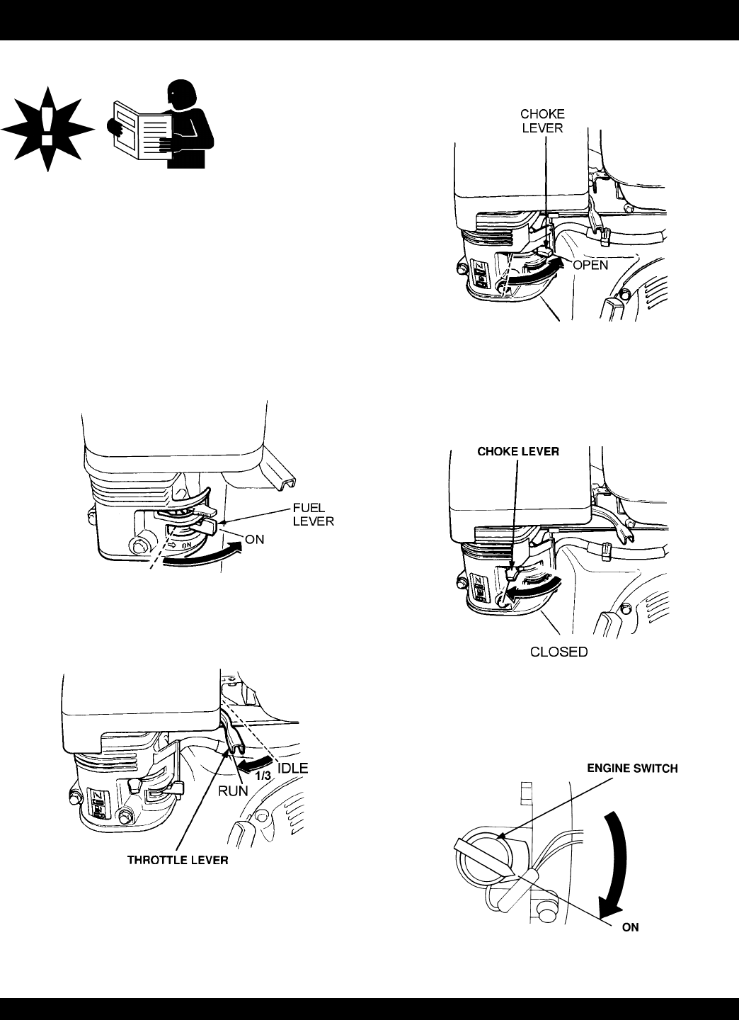
1. Place the engine
fuel valve lever
(Figure 6) to the "ON"
position.
DO NOT attempt to operate the pump until the Safety, General
Information and Inspection sections of this manual have been
read and thoroughly understood
.
2. Move the
throttle lever
(Figure 7) away from the slow
position, about 1/3 of the way toward the fast position.
Figure 6. Engine Fuel Valve Lever (ON Position)
Figure 7. Throttle Lever (1/3 Start Position)
3. Place the
choke lever
(Figure 8) in the "
OPEN
" position if
starting a
cold
engine.
4. Place the
choke lever
(Figure 9) in the "
CLOSED
" position
if starting a
warm engine
or the
temperature is warm.
Figure 8. Engine Choke Lever (Open)
Figure 9. Engine Choke Lever (Closed)
5. Place the
engine ON/OFF switch
(Figure 10) in the "
ON
"
position.
Figure 10. Engine ON/OFF Switch (ON Position)
This section is intended to assist the operator with the
initial
start-up
of the trash pump. It is extremely important that this
section be read carefully before attempting to use the pump in
the field.
CAUTION :
PAGE 18 —STOW T-20H TRASH PUMP — PARTS MANUAL — REV. #0 (05/29/03)
STOW T-20H — INITIAL START-UP (ENGINE)
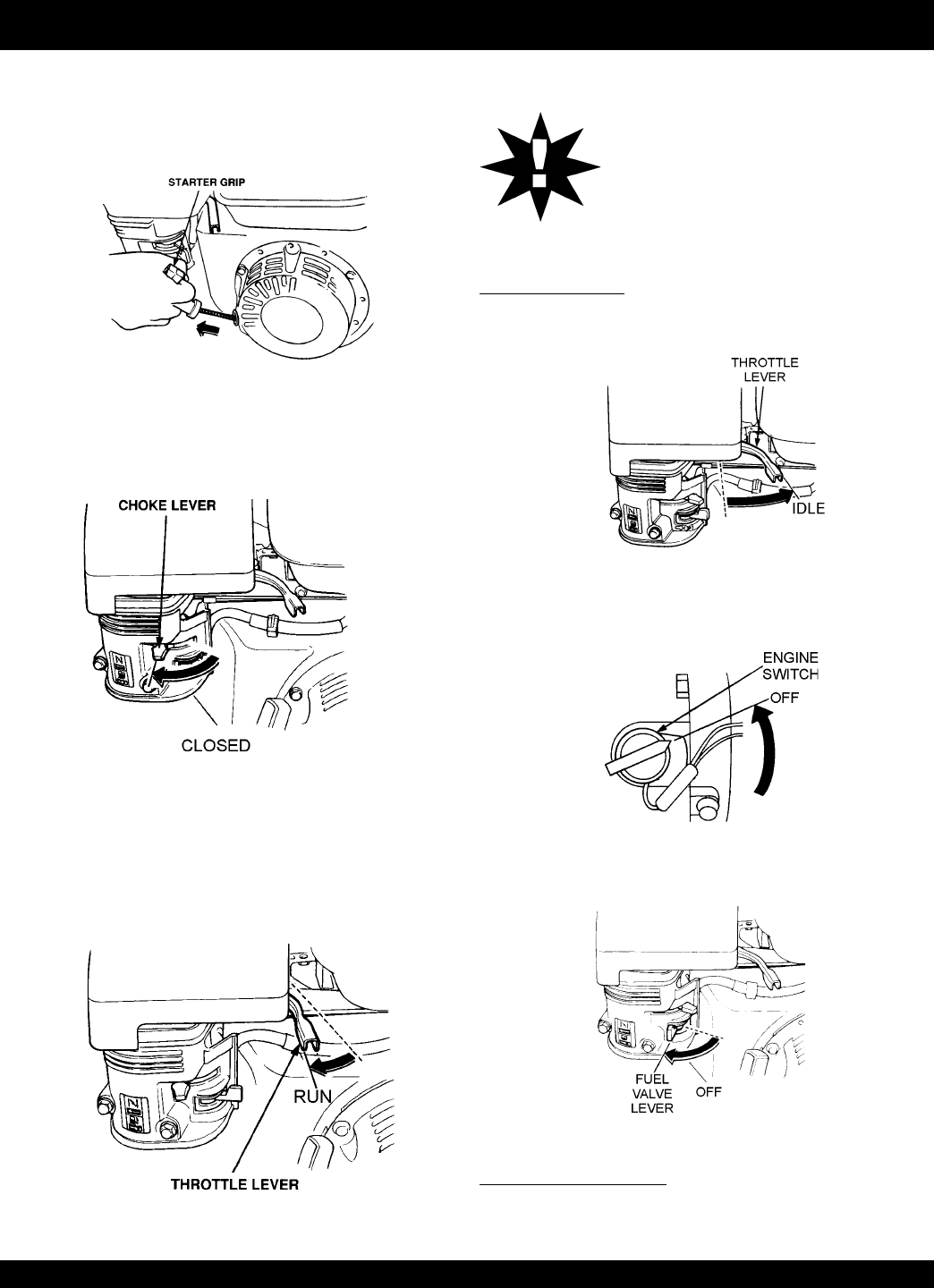
6. Grasp the starter grip (Figure 11) and slowly pull it out. The
resistance becomes the hardest at a certain position, corre-
sponding to the compression point. Pull the starter grip briskly
and smoothly for starting.
7. If the engine has started, slowly return the choke lever
(Figure 12 ) to the
CLOSED
position. If the engine has not
started repeat steps 1 through 6.
Figure 11. Starter Grip
8. Before the pump is placed into operation, run the engine for
several minutes. Check for fuel leaks, and noises that would
associate with a lose component.
9. To begin pumping, place the throttle lever (Figure 13) in the
"
RUN
"position.
Figure 12. Choke Lever (Closed)
Figure 13. Throttle Lever (Run)
Stopping The Engine
Normal Shutdown
1. Move the throttle lever to the IDLE position (Figure 14) and
run the engine for three minutes at low speed.
Figure 14. Throttle Lever (Idle)
2. After the engine
cools
, turn the engine ON/OFF switch to the
“OFF” position (Figure 15).
3. Place the
fuel shut-off lever
(Figure 16) in the OFF
position.
Figure 15. Engine ON/OFF Switch (OFF)
Figure 16. Fuel Valve Lever (OFF)
Emergency Showdown
1. Move the throttle lever quickly to the
IDLE
position, and place
the engine ON/OFF switch in the
OFF
position.
CAUTION :
ALWAYS run engine at
full speed
while
pumping.

STOW T-20H TRASH PUMP — PARTS MANUAL— REV. #0 (05/29/03) — PAGE 19
NOTE PAGE
PAGE 20 —STOW T-20H TRASH PUMP — PARTS MANUAL — REV. #0 (05/29/03)
STOW T-20H — MAINTENANCE (PUMP)
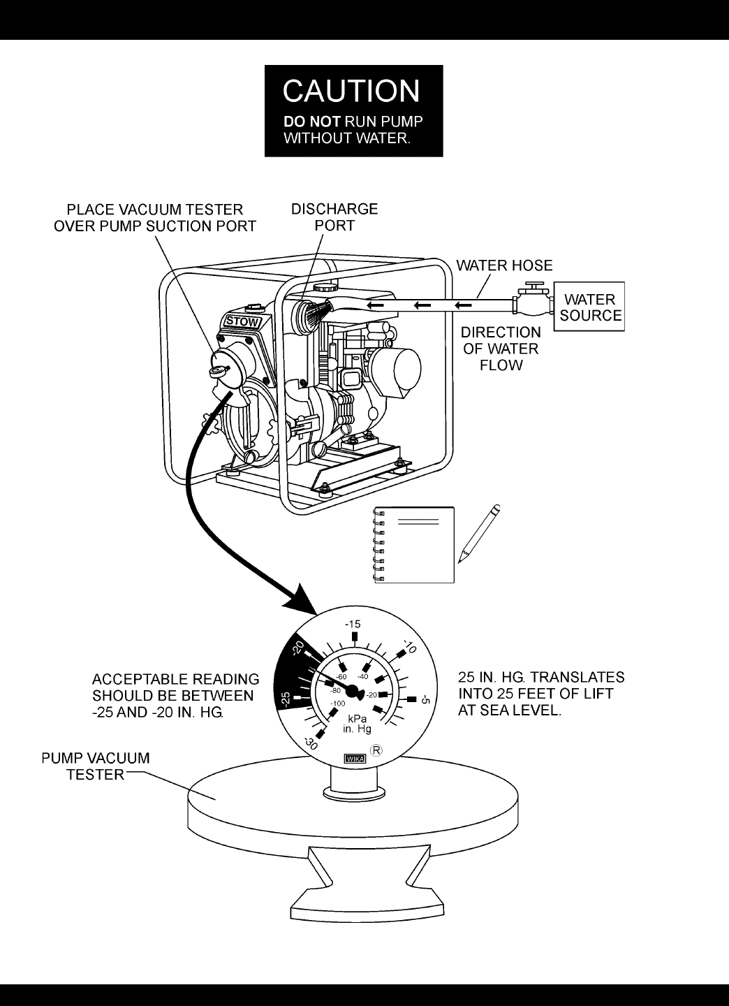
To perform the pump vacuum test do the following:
1. Remove the pump fill cap (Figure 2), and fill the pump
with water.
2. Start the engine as outlined in the initial start-up section,
and wait for the pump to begin pumping.
3. As shown in Figure 17 (next page), place a water hose
inside the discharge opening of the pump, and turn on
the water. This flow of water into the discharge opening
will
prevent
the pump from running dry.
4. Place the
Pump Vacuum Tester
(P/N 7000030)
over
the pump suction (inlet) opening (Figure 17) with the
vacuum gauge facing upwards. It may be necessary to
apply a small amount of water around the rubber seal of
the vacuum tester to make a good suction fit.
5. Check and make sure that there are no air leaks between
the vacuum tester and the inlet port on the pump. If air
leaks are present reseat vacuum tester.
6. Run the pump for a few minutes while monitoring the
vacuum gauge. If the gauge indicates a reading between
-25 and -20 in. Hg. (inches of mercury) then it can be
assumed that the pump is working correctly.
Pump Vacuum Test
CAUTION :
DO NOT attempt to start the engine unless
the pump has previously been
primed
with
water. Severe pump damage will occur if
pump has not been primed.
Adjusting Impeller Clearance
1. If it is necessary to replace impeller or volute, be sure
clearance between impeller and volute is adjusted
correctly.
2. The impeller should be as close to the volute as possible
without rubbing against it. Clearance is adjusted by
adding or removing
shims
from behind the impeller.
3. Check clearance between impeller and insert by slowly
pulling starter rope to turn impeller. Remove spark plug
to make it easier to turn impeller.
25 in. Hg (inches of mercury)
translates into 25 feet of lift at
sea
level
.
NOTE
7. If the vacuum tester gauge indicates a reading
below
-20 in. Hg, it can then be assumed that the pump
is not functioning correctly, and corrective action needs
to be taken.
6. To test the
flapper valve
, shut down the engine. The
vacuum tester should remain attached to the pump
suction inlet port by vacuum. This indicates the pump's
flapper valve is seating properly to hold water in the
suction hose when the engine is stopped. This prevents
backflow and allows for faster priming when the engine
is restarted.
It is important not to remove too
many shims or the clearance
between the impeller and volute
will become
too wide
and pump
performance will be reduced.
Remember as the impeller wear
down, additional shims may be required to maintain the
clearance between the impeller and insert.
4. Check the impeller
every six months
for wear, and for
clearance between the impeller face and the volute. Also
check the shaft seal for wear, as well as the shaft sleeve.
Pump Cleaning
After pumping water containing large amounts of dirt and
debris, perform the following:
1. Remove the drain plug from the pump housing (Figure 2)
and drain any water left in the pump.
2. Loosen the two locking hand knobs (turn counter-
clockwise) and remove
clean-out cover
.
3. Clean and remove dirt, debris from pump casing. Inspect
impeller and volute for wear. Replace any damaged or
worn parts.
CAUTION :
The impeller may develop
sharp edges
.
Use extreme care when cleaning around
the impeller to prevent being cut.
NOTE
STOW T-20H TRASH PUMP — PARTS MANUAL— REV. #0 (05/29/03) — PAGE 21
STOW T-20H — MAINTENANCE (PUMP)
Figure 17. Pump Vacuum Tester
Pressure reading may vary
depending on altitude. See Tables 3
and 4 on page 12.
NOTE
PAGE 22 —STOW T-20H TRASH PUMP — PARTS MANUAL — REV. #0 (05/29/03)
STOW T-20H — MAINTENANCE (ENGINE)
Reference manufacturer engine
manual for specific servicing
instructions.
NOTE
Engine Maintenance
Perform engine maintenance procedures as referenced by
Table 6 below:
eludehcSecnanetniaMenignE.6elbaT
)3(NOITPIRCSEDNOITAREPOEROFEB
TSRIF
HTNOM
RO
.SRH01
YREVE
SHTNOM3
RO
.SRH52
YREVE
SHTNOM6
RO
.SRH05
YREVE
RAEY
RO
.SRH001
YREVE
SRAEY2
RO
.SRH002
liOenignE
KCEHCX
EGNAHCX
renaelCriA
KCEHCX
EGNAHC)1(X
stloB&stuNllA fInethgit-eR
yrasseceN X
gulPkrapS
NAELC-KCEHCX
ECALPER X
sniFgnilooCKCEHCX
retserrAkrapSNAELC X
knaTleuFNAELC X
retliFleuFKCEHC X
deepSeldITSUJDA-KCEHC )2(X
ecnaraelCevlaVTSUJDA-KCEHC )2(X
senilleuFKCEHC )2()yrassecenfiecalper(sraey2yrevE
nidesunehwyltneuqerferomecivreS)1( YTSUD .saera
yllacinahcemeradnaslootreporpehtevahuoysselnu,relaedcivresruoyybdecivresebdluohssmetiesehT)2(
serudecorpecivresroflaunaMpohsADNOHehtotrefeR.tneiciforp
.slavretniecnanetniamreporpenimretedotnoitarepofosruohgol,esulaicremmocroF)3(
STOW T-20H TRASH PUMP — PARTS MANUAL— REV. #0 (05/29/03) — PAGE 23
Maintenance
Perform the engine maintenance procedures as indicated below:
DAILY
■
Thoroughly remove dirt and oil from the engine and control
area. Clean or replace the air cleaner elements as necessary.
Check and retighten all fasteners as necessary. Check the
spring box and bellows for oil leaks. Repair or replace as
needed.
WEEKLY
■
Remove the fuel filter cap and clean the inside of the fuel
tank.
■
Remove or clean the filter at the bottom of the tank.
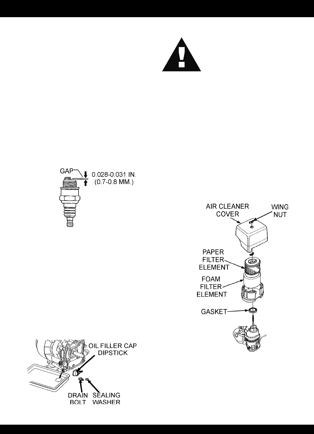
■
Remove and clean the spark plug (Figure 18), then adjust
the spark gap to 0.028 ~0.031 inch (0.6~0.7 mm). This unit
has electronic ignition, which requires no adjustments.
Figure 20. Engine Air Cleaner
DO NOT use gasoline as a cleaning solvent,
because that would create a risk of fire or
explosion.
DANGER :
ENGINE AIR CLEANER
1. Remove the air cleaner cover and foam filter element as
shown in Figure 20.
2. Tap the paper filter element (Figure 20) several times on a
hard surface to remove dirt, or blow compressed air [not
exceeding 30 psi (207 kPa, 2.1 kgf/cm2)] through the filter
element from the air cleaner case side.
NEVER
brush off dirt.
Brushing will force dirt into the fibers. Replace the paper filter
element if it is excessively dirty.
3. Clean foam element in warm, soapy water or nonflammable
solvent. Rinse and dry thoroughly. Dip the element in clean
engine oil and completely squeeze out the excess oil from the
element before installing.
ENGINE OIL
1. Drain the engine oil when the oil is
warm
as shown in
Figure 19.
2. Remove the oil drain bolt and sealing washer and allow
the oil to drain into a suitable container.
3. Replace engine oil with recommended type oil as listed
in Table 5. Engine oil capacity is 1.16 quarts (1.1 liters).
DO NOT overfill.
4. Install drain bolt with sealing washer and tighten se-
curely.
Figure 19. Engine Oil (Draining)
Figure 18. Spark Plug Gap
STOW T-20H — MAINTENANCE (ENGINE)

PAGE 24 —STOW T-20H TRASH PUMP — PARTS MANUAL — REV. #0 (05/29/03)
STOW T-20H — PREPARATION FOR LONG -TERM STORAGE
Pump Storage
For storage of the pump for over 30 days, the following is
required:
z
Drain the fuel tank completely.
z
Run the engine until the fuel in the injection system is
completely consumed.
z
Completely drain used oil from the engine crankcase
and fill with fresh clean oil, then follow the procedures
described in the engine manual for engine storage.
z
Remove the drain plug from the pump and drain out any
water from left in the housing.
z
Remove the pump cover and clean inside of pump
housing. Coat inside of pump housing with a light film of
oil to reduce corrosion. A spray can of oil works well for
this application.
z
Cover suction and discharge ports with duct tape to
prevent any foreign matter from falling into pump.
z
Cover pump and engine with plastic covering or
equivalent and store in a clean, dry place.
z
To protect the water cooled-seals, place one-half pint of
lubricating oil (new or used) through the discharge opening
on the pump and crank the engine several times. This
will prevent excessive corrosion and also keep the
mechanical seal lubricated.

STOW T-20H TRASH PUMP — PARTS MANUAL— REV. #0 (05/29/03) — PAGE 25
NOTE PAGE

PAGE 26 —STOW T-20H TRASH PUMP — PARTS MANUAL — REV. #0 (05/29/03)
STOW T-20H — TROUBLESHOOTING (ENGINE)
GNITOOHSELBUORTENIGNE.7ELBAT
MOTPMYS MELBORPELBISSOP NOITULOS
tratsottluciffiD
gulpkrapstubelbaliavasileuF
elbaliavarewoP(.etingitonlliw
.)elbacnoisnethgihta
?egdirbgniebgulpnoitingI .metsysnoitingikcehC
?noitingitatisopednobraC .noitingiecalperronaelC
evitcefedoteudtiucrictrohS
?srotalusni
.srotalusniecalpeR
?pagkrapsreporpmI .pagtcerrocehtotpaggulpkrapsteS
gulpkrapstubelbaliavasileuF
rewoP(.etingitonlliw TON
.)elbacnoisnethgihtaelbaliava
?hctiwspotstatiucrictrohS .evitcefedfihctiwspotsecalpeR.tiucrichctiwspotskcehC
?evitcefedliocnoitingI .liocnoitingiecalpeR
gulpkrapsdnaelbaliavasileuF
noisserpmoc(setingi )lamron .
nobrachtiwdeggolcrelffuM
?stisoped
.relffumecalperronaelC
siytilauqleufdexiM
?etauqedani
.erutximliootleufkcehC
,retaw(etauqedaniesunileuF
?)tsud
.leufhserfhtiwecalperdnametysleufhsulF
?deggolcrenaelCriA .renaelcriaecalperronaelC
gulpkrapsdnaelbaliavasileuF
noisserpmoc(setingi wol .)
?teksagdaehrednilycevitcefeD .teksagdaehecalperrostlobdaehrednilycnethgiT
?nrowrednilyC .rednilycecalpeR
?esoolgulpkrapS .gulpkrapsnehgiT
yrotcafsitastonnoitarepO
elbaliavarewophguonetoN
-ssimon,lamronnoisserpmoc(
.)gnirif
?deggolcrenaelcriA .renaelcriaecalperronaelC
?enilleufniriA .enilleufmorf)riaevomer(deelB
taolfrotaerubracnilevelleuF
?reporpmirebmahc taolfrotaerubractsujdA
?rednilycnistisopednobraC rednilycecalperronaelC
elbaliavarewophguonetoN
-ssim,lamronnoisserpmoc(
.)gnirif
?evitcefedliocnoitingI .leufhserfhtiwecalperdnametysleufhsulF
?strohsnetfogulpnoitingI .noitinginaelc,seriwnoitingiecalpeR
,retaw(etauqedaniesunileuF
?)tsud
.leufhserfhtiwecalperdnametysleufhsulF
.staehrevoenignE
ninoitsopednobracevissecxE
?rebmahcnoitsubmoc
.esacknarcecalperronaelC
htiwdeggolcrelffumrotsuahxE
.nobrac
.relffumecalperronaelC
?tcerrocnieulavtaehgulpkrapS .gulpkrapsepyttcerrochtiwgulpkrapsecalpeR
STOW T-20H TRASH PUMP — PARTS MANUAL— REV. #0 (05/29/03) — PAGE 27
STOW T-20H — TROUBLESHOOTING (ENGINE/PUMP)
)deunitnoC(GNITOOHSELBUORTENIGNE.7ELBAT
MOTPMYS MELBORPELBISSOP NOITULOS
yrotcafsitastonnoitarepO
.setautculfdeepslanoitatoR
?reporpmitnemtsujdaronrevoG .reveltcerrocotronrevogtsujdA
?evitcefedgnirpsronrevoG .noitingiecalperronaelC
?citarrewolfleuF .enilleufkcehC
noitcushguorhtninekatriA
?enil
.enilnoitcuskcehC
gnikrowtonretratslioceR
.ylreporp
?trapgnitatornitsuD .ylbmessaretratsliocernaelC
?eruliafgnirpsgnirpS .gnirpslairpsecalpeR
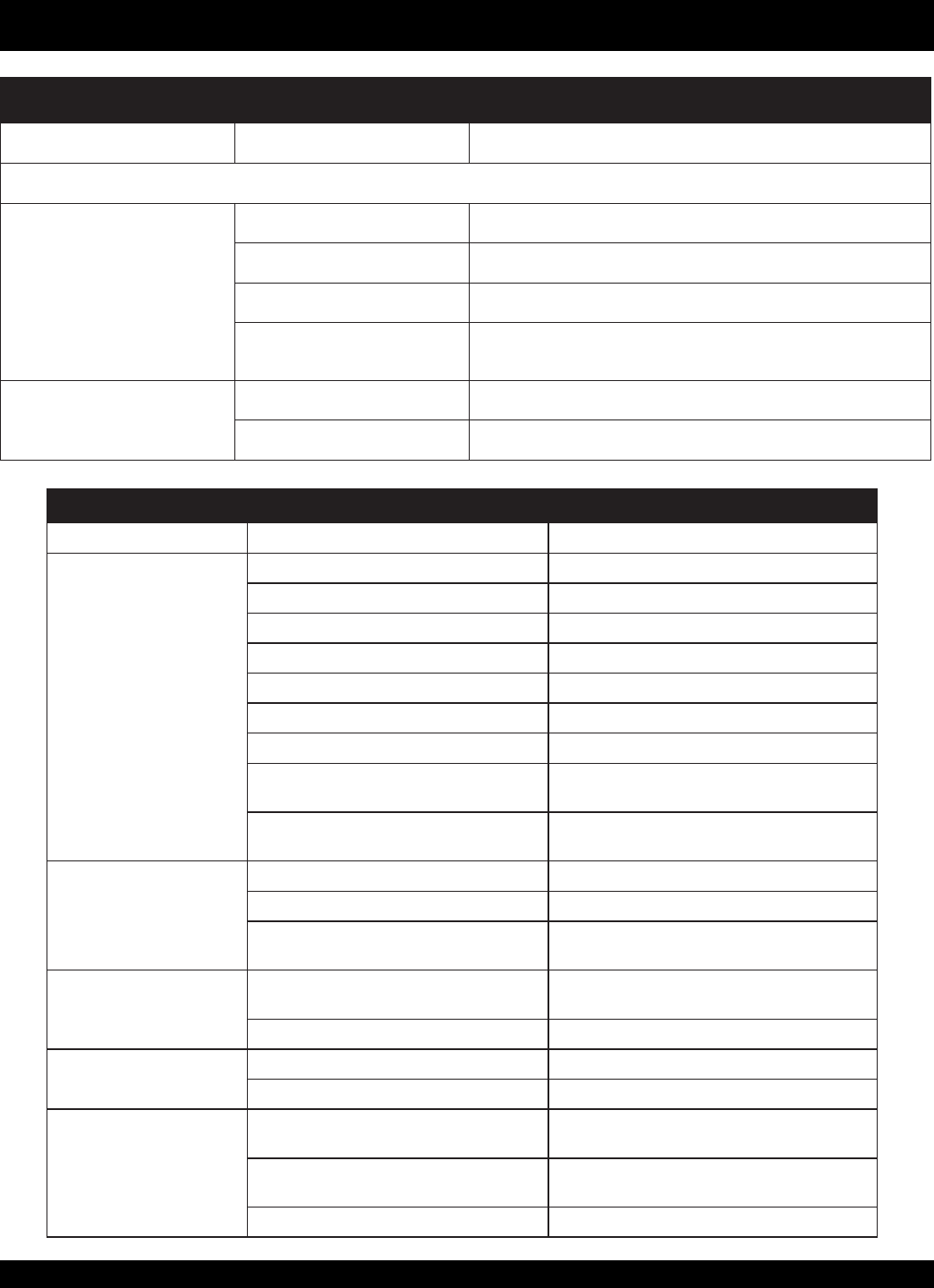
GNITOOHSELBUORTPMUP.8ELBAT
MOTPMYSMELBORPELBISSOPNOITULOS
.retawnoekattonseodpmuP
?gnisuohehtniretawgnimirphguonetoN.retawddA
?wolootdeepsenignE.elttorhtesaercnI
?deggulprenniartS.reniartsnaelC
?degamadesohnoitcuS spmalcdna,esohriaperroecalpeR
?tropnoitcustakaelriA .delaesylreporpdnathgiterasgnittiftahtkcehC
?enilretawevobahgihootdetacolsipmuP .retawotresolcpmupevoM
?gnisuohpmupnignitcellocsirbeD.gnisuohpmupnaelC
.etulovdnarellepmineewtebecnatsidhcumooT .rellepmiecalperrosmihsgniddaybecnaraelctsujdA
"020..xaM-"600..niM
dnapmupneewtebelohpeewtuognikaelretaW
?enigne
,steksagdnalaeslacinahcemfonoitidnockcehC
.gnisuohenignednadnepmupneewteb
onroelttil,retawnisekatpmuP
.egrahcsid
?wolootdeepsenignE .deepselttorhtesaercnI
?deggulpyllaitrapreniartsnoitcuS.reniartsnaelC
?nrowetuloV/rellepmI ecalperrosmihsgniddaybecnaraelctsujdA
etulov/rellepmi
.telnitaskaelesohnoitcuS ?ylreporpdelaestoneraspmalc/sgnittiF noslaesartxepeeK(.pmalcddaroecalper,nethgiT
)pmup
?egralootsiretemaidesoH .esohecalperroesohretemaidrellamsesU
noyatstonseodegrahcsiD
.gnilpuoc
?hgihooterusserP .pmalclanoitiddadda,erusserpkcehC
?dekcolbdnerodeknikesoH.esohkcehC
sipmup:nruttonseodrellepmI
.tratsotdrah
?dekcolbrodemmajrellepmI morfsirbeddnatridnaelcdnarevocpmupnepO
.gnisuohedisni
?gnidnibetulovdnarellepmI dnihebmorfmihsgnivomerybecnaraelctsujdA
.rellepmi
?enigneevitcefeD .launaMs'renwOenignEeeS
PAGE 28 —STOW T-20H TRASH PUMP — PARTS MANUAL — REV. #0 (05/29/03)
How to read the marks and remarks used in this parts
book.
Items Found In the “Remarks” Column
Serial Numbers-Where indicated, this indicates a serial
number range (inclusive) where a particular part is used.
Model Number-Where indicated, this shows that the
corresponding part is utilized only with this specific model
number or model number variant.
Items Found In the “Items Number” Column
All parts with same symbol in the number column, *, #, +, %, or
>
, belong to the same assembly or kit..
NOTE
If more than one of the same
reference number is listed, the
last one listed indicates newest (or
latest) part avaliable.
The contents of this catalog are
subject to change without notice
.
NOTE
STOW T-20H — EXPLANATION OF CODE IN REMARKS COLUMN
STOW T-20H TRASH PUMP — PARTS MANUAL— REV. #0 (05/29/03) — PAGE 29
STOW T-20H — SUGGESTED SPARE PARTS
NOTE
Part number on this Suggested
Spare Parts List may super cede/
replace the P/N shown in the text
pages of this book.
STOW T-20H TRASH PUMP 1 TO 3 UNITS WITH
HONDA GX160K1TX2 ENGINE
Qty. P/N Description
2 ............ KITT20H ............... KIT, PUMP, MECHANICAL SEAL, O-RINGS
2 ............ 0631211101 .......... DRAIN CAP, FLOODING
2 ............ 0480350300 .......... O-RING FLOODING DRAIN CAP
1 ............ 0811582543 .......... MECHANICAL SEAL SLEEVE
1 ............ 0480240160 .......... O-RING, MECHANICAL SEAL SLEEVE
1 ............ 9395030030 .......... IMPELLER
3 ............ 17210ZE1505 ....... ELEMENT AIR CLEANER DUAL
3 ............ 9807956846 .......... SPARK PLUG
1 ............ 17620ZH7023 ....... CAP, FUEL WITH GASKET
1 ............ 28462ZH8003 ....... ROPE STARTER
1 ............ 1317350350 .......... CHECK VALVE
PAGE 30 —STOW T-20H TRASH PUMP — PARTS MANUAL — REV. #0 (05/29/03)
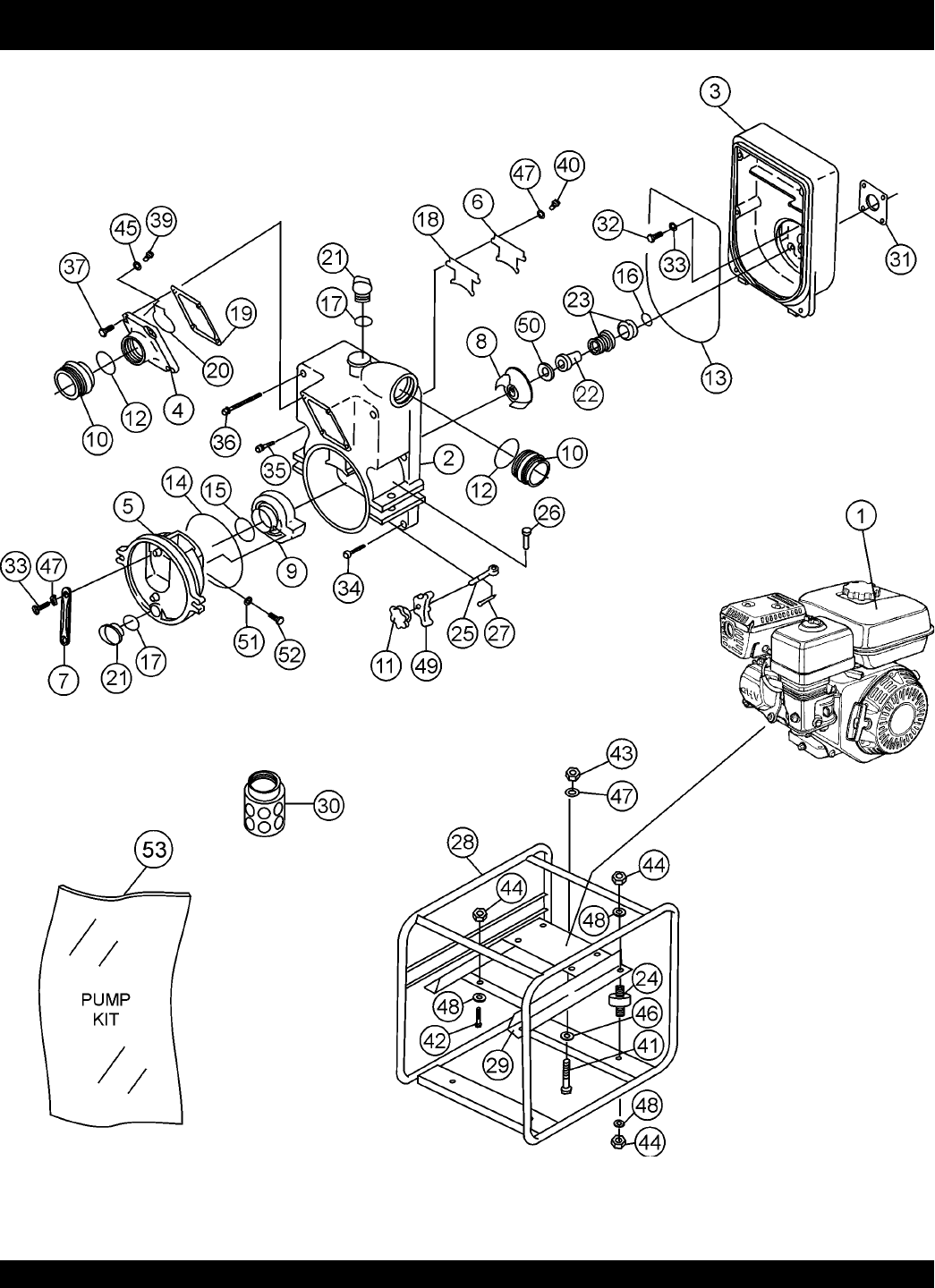
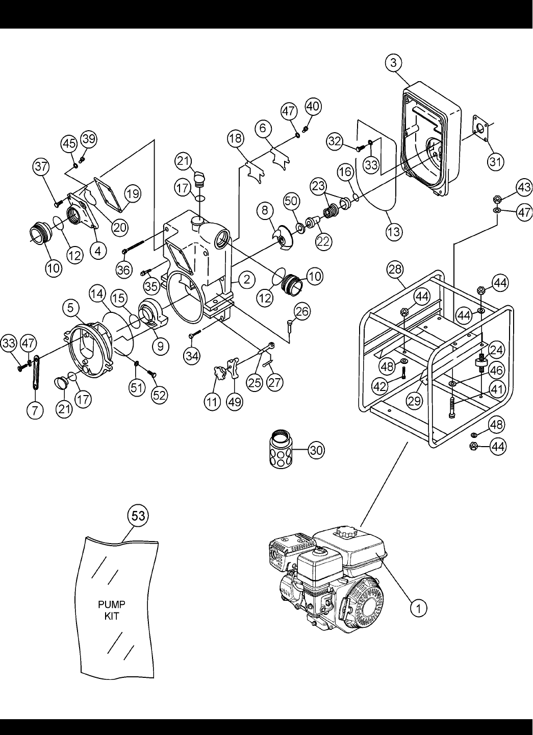
STOW T-20H — PUMP ASSY.
PUMP ASSY.

STOW T-20H TRASH PUMP — PARTS MANUAL— REV. #0 (05/29/03) — PAGE 31
STOW T-20H — PUMP ASSY.
PUMP ASSY.
NO. PART NO. PART NAME QTY.REMARKS
1 GX160K1TX2 ENGINE, HONDA 1
2 1841100010 CASING NPS3" 1
3 9349100020 CASING COVER 1
4 1841100160 SUCTION COVER NPS3" 1
5 1841100171 DRAIN COVER 1
6 1841100740 SUCTION PLATE 1
7 1247100250 DRAIN COVER HANDLE 1
8 1841040030 IMPELLER 1
9 1841000131 VOLUTE CASING 1
10 07904330200014 NIPPLE NPS3"×NPT3" 2
11 92950001900014 DRAIN COVER SET HANDLE 2
12 0483400700 O’RING (NIPPLE) 2
13*0489353850 O’RING (CASING) f3.5×f385 1
14*0489452300 O’RING (DRAIN COVER) f4.7×f230 1
15*0482200750 O’RING (VOLUTE CASING) 1
16*0480240160 O’RING (MECHANICAL SEAL S 1
17 0480350300 O’RING (FLOODING DRAIN CAP 2
18 1841330410 PACKING, SUCTION PLATE 1
19 1269330370 PACKING, SUCTION COVER 1
20 1317350350 CHECK VALVE 1
21 0631211101 CAP, FLOODING DRAIN 2
22 0811582543 MECHANICAL SEAL SLEEVE ............................ 1 ............... f25.4XF30X56L
23*0801123325 MECHANICAL SEAL ........................................... 1 ............... CERAMIC×CUB F30
24 0723302040 CUSHION RUBBER 4
25 1841200270 BOLT, HINGE M16×90 2
26 1247220280 PIN, HINGE f12×65 2
27 0641400430 SPLIT PIN 4×30 2
28 92952140100018 PIPE FRAME 1
29 18412140200018 ENGINE BASE 1
30 07472304050 STRAINER NPT2" 1
31 1201390610 PLATE, CASING COVER SET 1
32 0191150525 BOLT (CASING COVER) M8X20 4
33 0451250080 SEAL WASHER M8 4
34 0131151235 CAP SCREW (CASING) M12×35 2
35 0135051235 CAP SCREW SET W/SEAL RING M12×35 2
36 0135051295 CAP SCREW SET W/SEAL RING M12×95 2
37 0131150830 CAP SCREW (SUCTI ON) M8×30 4
38 0141050825 SCREW (DRAIN COVER HANDLE) M8×25 2
39 0141090510 SCREW (CHECK VALVE) M5×10 2
40 0181050820 BOLT WITH SPRING WASHER M8×20 2
41 0105050840 BOLT (ENGINE) M8×40 4
42 0105051035 BOLT (PUMP) M10×35 2
43 0209150080 FLANGE NUT (ENGINE) M8 4
44 0205450100 NUT (PUMP CUSHION RUBBER) M10 10
45 0401450050 WASHER 2
PAGE 32 —STOW T-20H TRASH PUMP — PARTS MANUAL — REV. #0 (05/29/03)
PUMP ASSY.
STOW T-20H — PUMP ASSY.

STOW T-20H TRASH PUMP — PARTS MANUAL— REV. #0 (05/29/03) — PAGE 33
46 0401450080 WASHER M8 2
47 0451250080 SPRING WASHER M8 2
48 0451250100 SPRING WASHER M10 10
49 18410002000014 DRAIN COVER PUSH PLATE 2
50*0852832516 ADJUST LINER “45×25.4 t0.3 1
50-1*0852852516 ADJUST LINER “45×25.4 t0.5 1
51 0458220080 SEAL WASHER M8 2
52 0105090820 BOLT (VOLUTE CASING) M8×20 2
53 KITT20H KIT, PUMP ........................................................ 1 ......... INCLUDES ITEMS W/*
PUMP ASSY.
NO. PART NO. PART NAME QTY.REMARKS
STOW T-20H — PUMP ASSY.
PAGE 34 —STOW T-20H TRASH PUMP — PARTS MANUAL — REV. #0 (05/29/03)
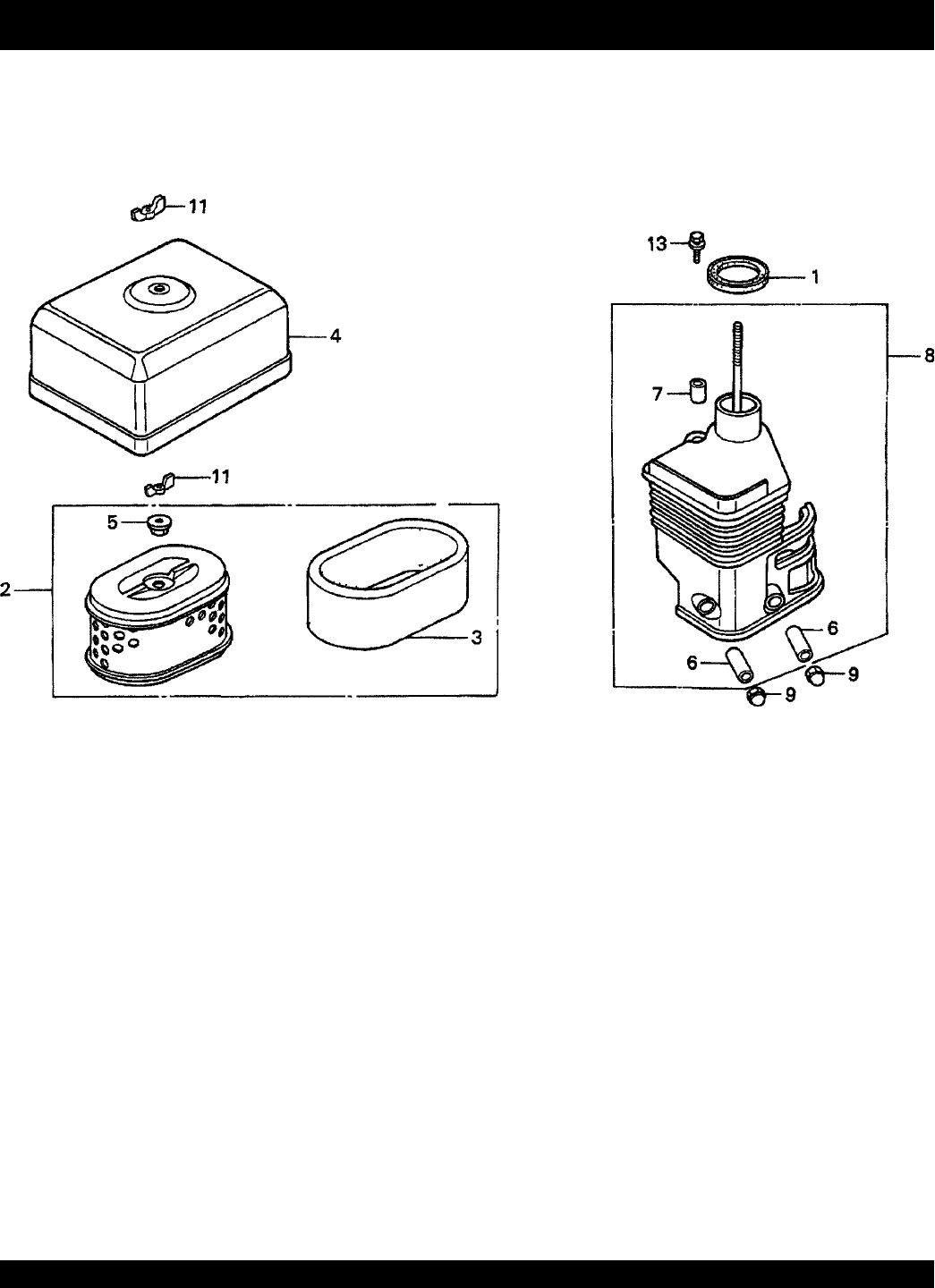
AIR CLEANER (DUAL) ASSY.
HONDA GX160K1TX2 ENGINE — AIR CLEANER (DUAL) ASSY.

STOW T-20H TRASH PUMP — PARTS MANUAL— REV. #0 (05/29/03) — PAGE 35
AIR CLEANER (DUAL) ASSY.
NO. PART NO. PART NAME QTY.REMARKS
1 16271ZE1000 GASKET, ELBOW 1
2 17210ZE1505 ELEMENT, AIR CLEANER (DUAL) ............... 1 ...... INCLUDES ITEMS W/*
3*17218ZE1505 FILTER (OUTER) 1
4 17230ZE1820 COVER, AIR CLEANER (DUAL) 1
5*17232891000 GROMMET, AIR CLEANER 1
6#17238ZE7010 COLLAR, AIR CLEANER 2
7#17239ZE1000 COLLAR B, AIR CLEANER 1
8 17410ZE1020 ELBOW, AIR CLEANER ............................... 1 ...... INCLUDES ITEMS W/#
9 90201415000 NUT, CAP (6 MM) 2
11 90325044000 WINGNUT, TOOL BOX SETTING 1
12 90325044000 WINGNUT, TOOL BOX SETTING 1
13 957010602000 BOLT, FLANGE (6 X 20) 1
HONDA GX160K1TX2 ENGINE — AIR CLEANER (DUAL) ASSY.
PAGE 36 —STOW T-20H TRASH PUMP — PARTS MANUAL — REV. #0 (05/29/03)
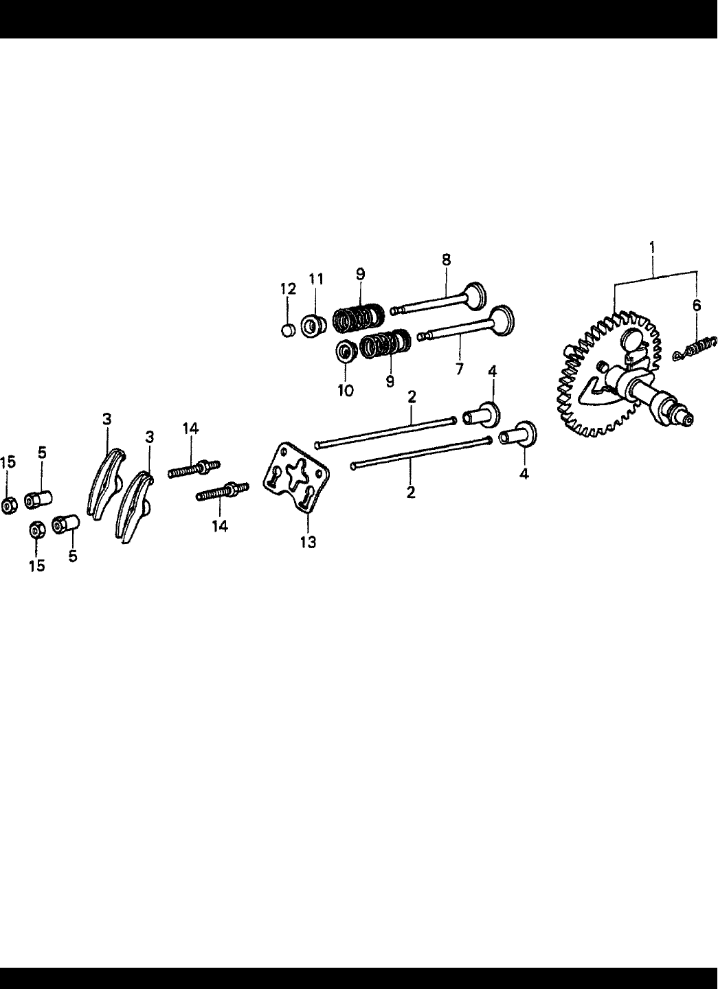
CAMSHAFT ASSY.
HONDA GX160K1TX2 ENGINE — CAMSHAFT ASSY.

STOW T-20H TRASH PUMP — PARTS MANUAL— REV. #0 (05/29/03) — PAGE 37
CAMSHAFT ASSY.
NO. PART NO. PART NAME QTY.REMARKS
1 14100ZE1812 CAMSHAFT ASSY. ...................................... 1 ...... INCLUDES ITEMS W/*
2 14410ZE1010 ROD, PUSH 2
3 14431ZE1000 ARM, VLAVE ROCKER 2
4 14441ZE1010 LIFTER, VALVE 2
5 14451ZE1013 PIVOT, ROCKER ARM 2
6*14568ZE1000 SPRING, WEIGHT RETURN 1
7 14711ZF1000 VALVE, IN. 1
8 14721ZH8810 VALVE, EX. (STELITE) 1
9 14751ZF1000 SPRING VALVE 2
10 14771ZE1000 RETAINER, IN. VALVE SPRING 1
11 14773ZE1000 RETAINER, EX. VALVE SPRING 1
12 14781ZE1000 ROTATOR, VALVE 1
13 14791ZE1010 PLATE, PUSH ROD GUIDE 1
14 90012ZE0010 BOLT, PIVOT (8MM) 2
15 90206ZE1000 NUT, PIVOT ADJ. 2
HONDA GX160K1TX2 ENGINE — CAMSHAFT ASSY.
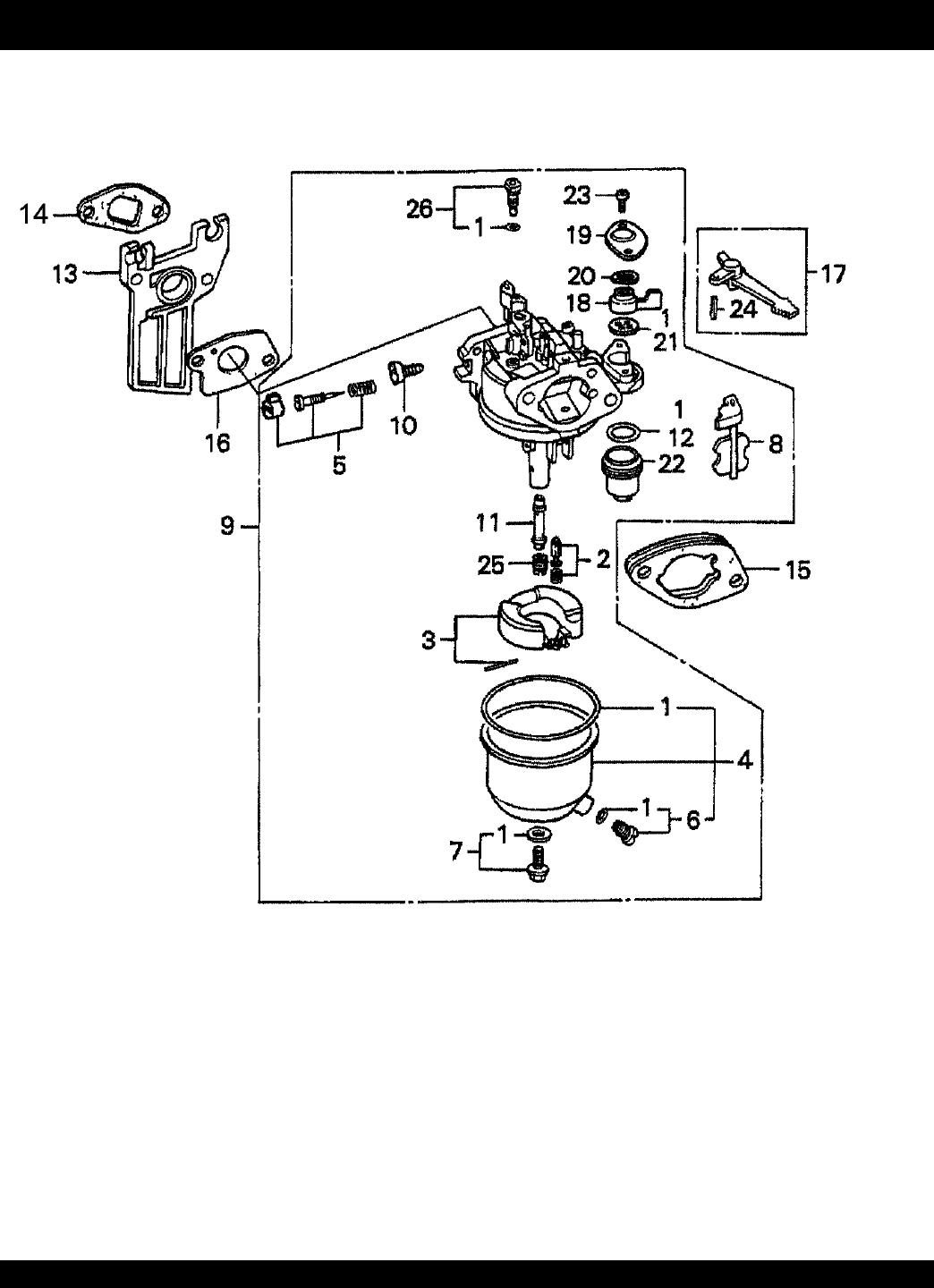
PAGE 38 —STOW T-20H TRASH PUMP — PARTS MANUAL — REV. #0 (05/29/03)
CARBURETOR ASSY.
HONDA GX160K1TX2 ENGINE — CARBURETOR ASSY.

STOW T-20H TRASH PUMP — PARTS MANUAL— REV. #0 (05/29/03) — PAGE 39
CARBURETOR ASSY.
NO. PART NO. PART NAME QTY.REMARKS
1V 16010ZE1812 GASKET SET 1
2*16011ZE0005 VALVE SET, FLOAT 1
3*16013ZE0005 FLOAT SET 1
4*16015ZE0831 CHAMBER SET, FLOAT 1
5*16016ZH7W01 SCREW SET 1
6*16024ZE1811 SCREW SET, DRAIN 1
7*16028ZE0005 SCREW SET B 1
8*16044ZE0005 CHOKE SET 1
9*16100ZH8W51 CARBURETOR ASSY. (BE65B B) ................ 1 ...... INCLUDES ITEMS W/*
10*16124ZE0005 SCREW, THROTTLE STOP 1
11*16166ZH8W50 NOZZLE, MAIN 1
12*16173001004 O-RING 1
13 16211ZE1000 INSULATOR, CARBURETOR 1
14 16212ZH8800 GASKET, INSULATOR 1
15 16220ZE1020 SPACER, CARBURETOR 1
16 16221ZH8801 GASKET, CARBURETOR 1
17 16610ZE1000 LEVER, CHOKE (STD) 1 INCLUDES ITEMS W/#
18*16953ZE1812 LEVER, VALVE 1
19*16954ZE1811 PLATE, LEVER SETTING 1
20*16956ZE1811 SPRING, VALVE LEVER 1
21*16957ZE1812 GASKET, VALVE 1
22*16967ZE0811 CUP, FUEL STRAINER 1
23*93500030060H SCREW, PAN (3 X 6) 2
24#9430520122 PIN, SPRING (2 X 12) 1
25 99101ZH80650 JET, MAIN (#65) OPTIONAL 1
25 99101ZH80680 JET, MAIN (#68) OPTIONAL 1
25*99101ZH80700 JET, MAIN (#70) 1
26*99204ZE00350 JET, SET, PILOT (#35) 1
HONDA GX160K1TX2 ENGINE — CARBURETOR ASSY.
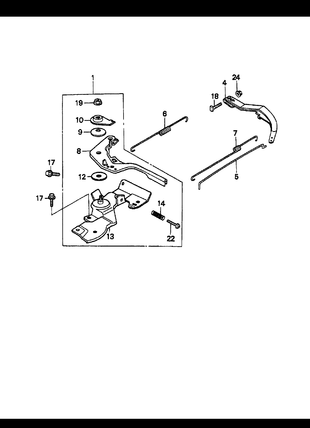
PAGE 40 —STOW T-20H TRASH PUMP — PARTS MANUAL — REV. #0 (05/29/03)
CONTROL ASSY.
HONDA GX160K1TX2 ENGINE — CONTROL ASSY.

STOW T-20H TRASH PUMP — PARTS MANUAL— REV. #0 (05/29/03) — PAGE 41
CONTROL ASSY.
NO. PART NO. PART NAME QTY.REMARKS
1 16500ZH8030 CONTROL ASSY. ......................................... 1 ...... INCLUDES ITEMS W/*
4 16551ZE0010 ARM, GOVERNOR 1
5 16555ZE1000 ROD, GOVERNOR 1
6 16561ZE1020 SPRING, GOVERNOR 1
7 16562ZE1020 SPRING, THROTTLE RETURN 1
8*16571ZH8020 LEVER, CONTROL 1
9*16574ZE1000 SPRING, LEVER 1
10*16575ZH8000 WASHER, CONTROL LEVER 1
12*16578ZE1000 SPACER, CONTROL LEVER 1
13*16580ZH8030 BASE, CONTROL 1
14*16584883300 SPRING, CONTROL ADJUSTING 1
17 90013883000 BOLT, FLANGE (6 X 12) (CT200) 2
18 90015ZE5010 BOLT, GOVERNOR ARM 1
19*90114SA0000 NUT, SELF-LOCK (6MM) 1
22*93500050250A SCREW, PAN (5 X 25) 1
24 9405006000 NUT, FLANGE (6MM) 1
HONDA GX160K1TX2 ENGINE — CONTROL ASSY.
PAGE 42 —STOW T-20H TRASH PUMP — PARTS MANUAL — REV. #0 (05/29/03)
CRANKCASE COVER ASSY.
HONDA GX160K1TX2 ENGINE — CRANKCASE COVER ASSY.

STOW T-20H TRASH PUMP — PARTS MANUAL— REV. #0 (05/29/03) — PAGE 43
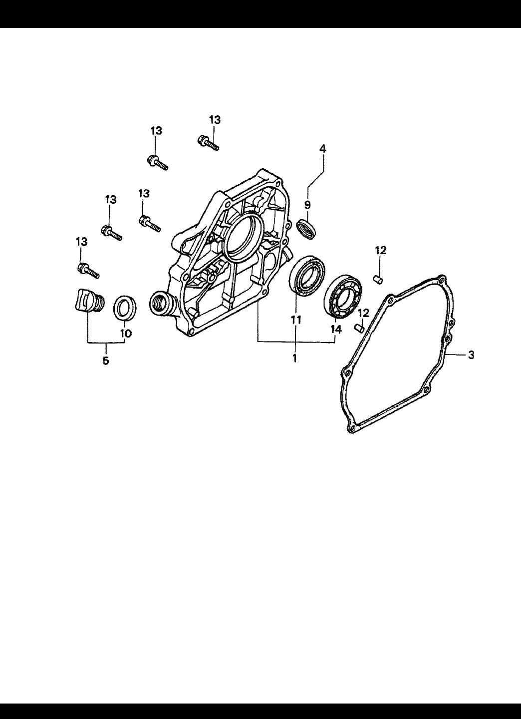
CRANKCASE COVER ASSY.
NO. PART NO. PART NAME QTY.REMARKS
1 11300ZE1641 COVER ASSY., CRANKCASE (U-TYPE) ..... 1 ...... INCLUDES ITEMS W/*
3 11381ZH8801 GASKET, CASE COVER 1
4 15600ZE1003 CAP ASSY., OIL FILLER ............................. 1 ...... INCLUDES ITEMS W/#
5 15600ZG4003 CAP ASSY., OIL FILLER ............................. 1 ...... INCLUDES ITEMS W/+
9#15625ZE1003 GASKET, OIL FILLER CAP 1
10+15625ZE1003 GASKET, OIL FILLER CAP 1
11*91202883005 OIL SEAL (25 X 41 X 6) 1
12 9430108140 PIN A, DOWEL (8 X 14) 2
13 957010803200 BOLT, FLANGE (8 X 32) 6
14*961006205000 BEARING, RADIAL BALL (6205) 1
HONDA GX160K1TX2 ENGINE — CRANKCASE COVER ASSY.
PAGE 44 —STOW T-20H TRASH PUMP — PARTS MANUAL — REV. #0 (05/29/03)
CRANKSHAFT ASSY.
HONDA GX160K1TX2 ENGINE — CRANKSHAFT ASSY.

STOW T-20H TRASH PUMP — PARTS MANUAL— REV. #0 (05/29/03) — PAGE 45
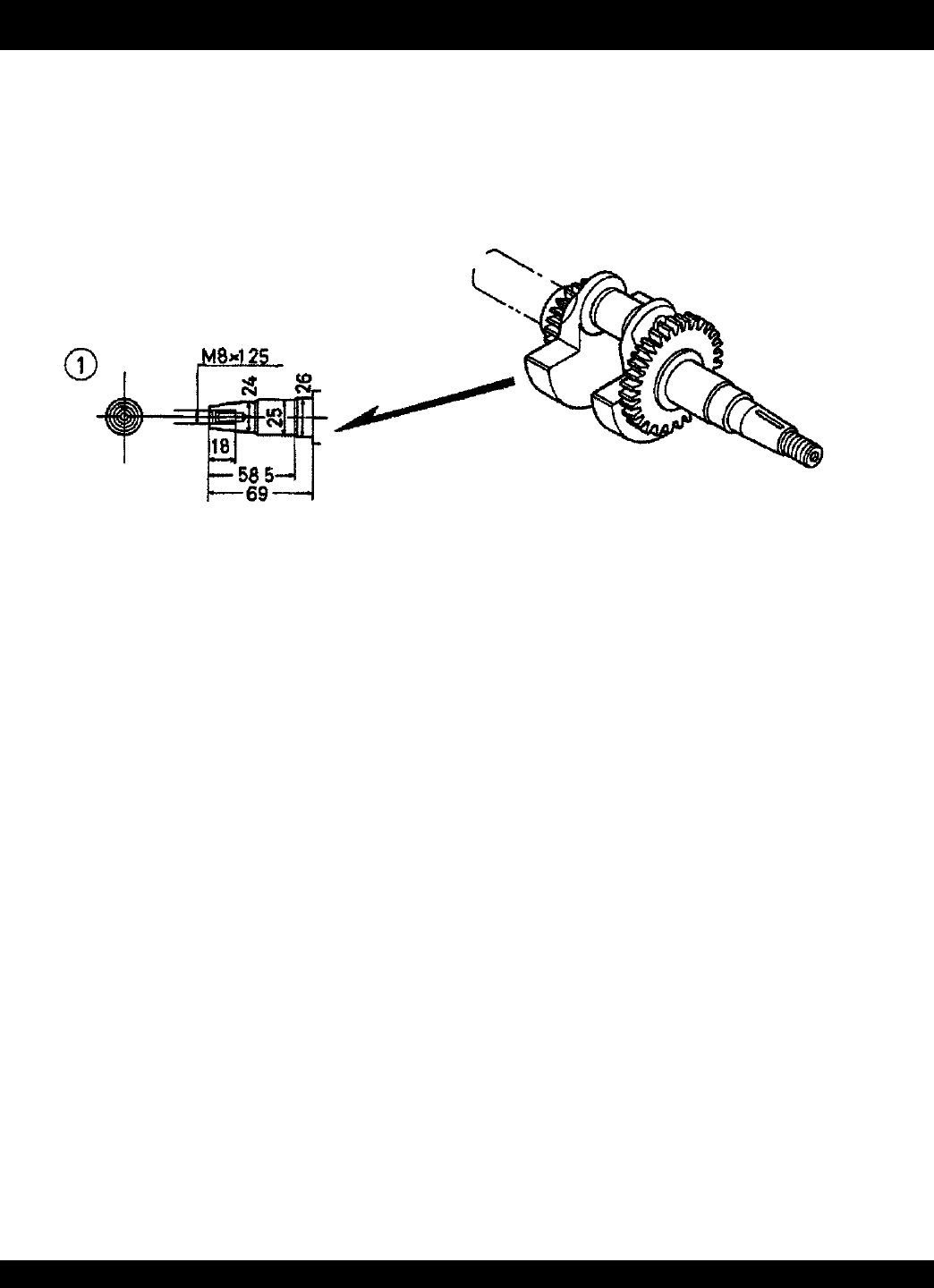
CRANKSHAFT ASSY.
NO. PART NO. PART NAME QTY.REMARKS
1 13310ZE1660 CRANKSHAFT (T-TYPE) 1
HONDA GX160K1TX2 ENGINE — CRANKSHAFT ASSY.
PAGE 46 —STOW T-20H TRASH PUMP — PARTS MANUAL — REV. #0 (05/29/03)
CYLINDER BARREL ASSY.
HONDA GX160K1TX2 ENGINE — CYLINDER BARREL ASSY.

STOW T-20H TRASH PUMP — PARTS MANUAL— REV. #0 (05/29/03) — PAGE 47
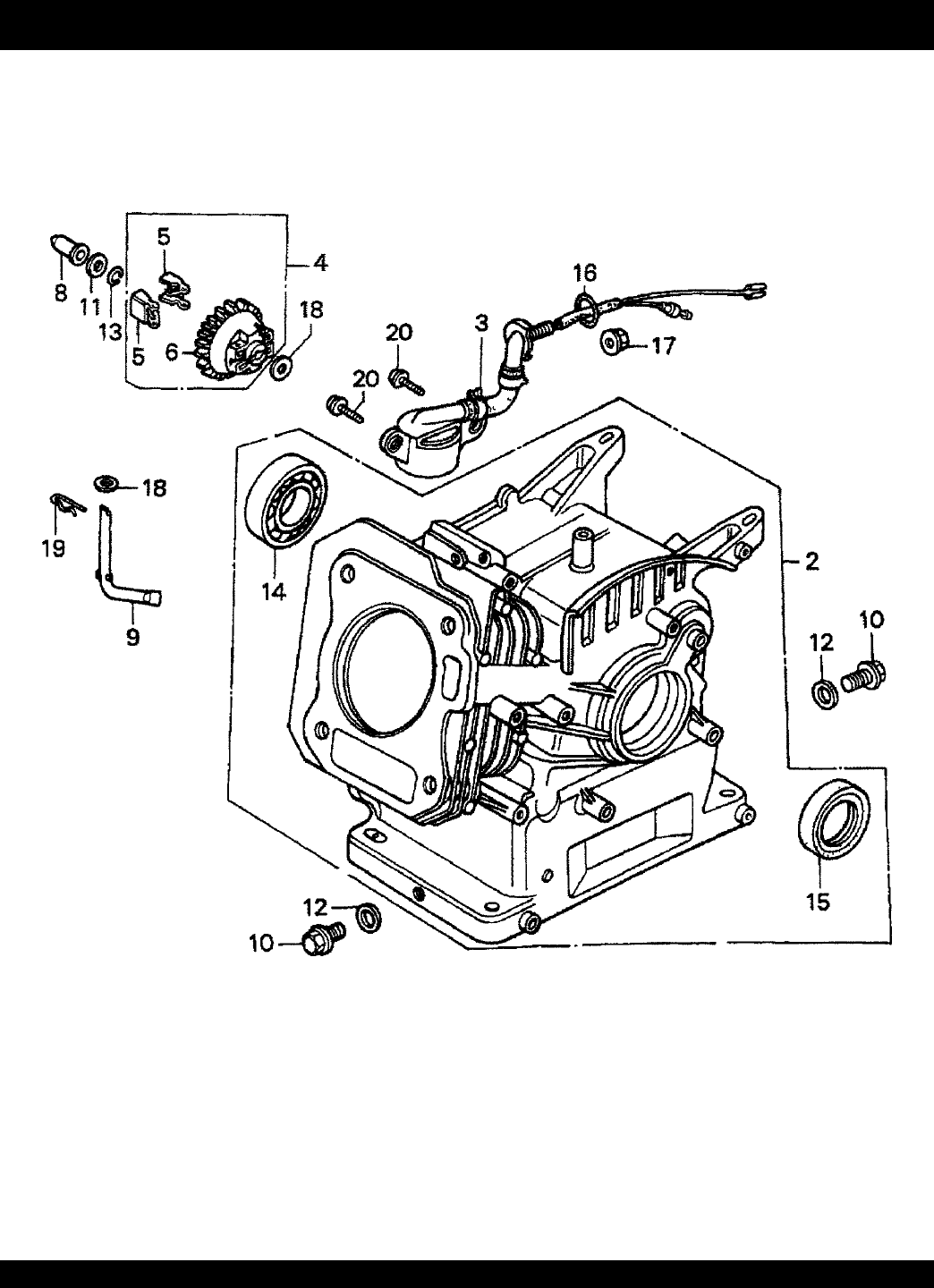
CYLINDER BARREL ASSY.
NO. PART NO. PART NAME QTY.REMARKS
2 12000ZH8811 CYLINDER ASSY. (OIL ALERT) ................... 1 ...... INCLUDES ITEMS W/*
3 15510ZE1023 SWITCH ASSY., OIL LEVEL ........................ 1 ...... USE UP TO ENGINE S/N 4367320
3 15510ZE1033 SWITCH ASSY., OIL LEVEL ........................ 1 ...... USE FROM ENGINE S/N 4367321
4 16510ZE1000 GOVERNOR ASSY. ...................................... 1 ...... INCLUDES ITEMS W/#
5#16511ZE1000 WEIGHT, GOVERNOR 2
6#16512ZE1000 HOLDER, GOVERNOR WEIGHT 1
8 16531ZE1000 SLIDER, GOVERNOR 1
9 16541ZE1000 SHAFT, GOVERNOR ARM 1
10 90131ZE1000 BOLT, DRAIN PLUG 2
11 90451ZE1000 WASHER, THRUST (6MM) 1
12 90601ZE1000 WASHER, DRAIN PLUG (10.2MM) 2
13 90602ZE1000 CLIP, GOVERNOR HOLDER 1
14*91001ZF1003 BEARING, RADIAL BALL (6205) 1
15*91202883005 OIL SEAL (25 X 41 X 6) 1
16 91353671003 O-RING (13.5 X 1.5) (ARAI) 1
17 9405010000 NUT, FLANGE (10MM) 1
18 9410106800 WASHER, PLAIN (6MM) 2
19 9425108000 PIN, LOCK (8MM) 1
20 957010601200 BOLT, FLANGE (6 X 12) 2
HONDA GX160K1TX2 ENGINE — CYLINDER BARREL ASSY.
PAGE 48 —STOW T-20H TRASH PUMP — PARTS MANUAL — REV. #0 (05/29/03)
CYLINDER HEAD ASSY.
HONDA GX160K1TX2 ENGINE — CYLINDER HEAD ASSY.

STOW T-20H TRASH PUMP — PARTS MANUAL— REV. #0 (05/29/03) — PAGE 49
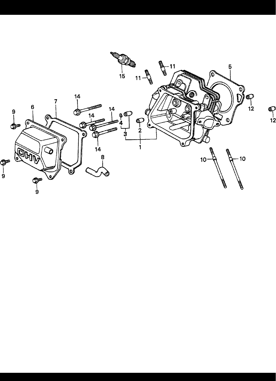
CYLINDER HEAD ASSY.
NO. PART NO. PART NAME QTY.REMARKS
1 12210ZH8000 CYLINDER HEAD ......................................... 1 ...... INCLUDES ITEMS W/*
2*12204ZE1306 GUIDE, VALVE (OS) (OPTIONAL) 1
3*12205ZE1315 GUIDE, EX. VALVE (OS) (OPTIONAL) ........ 1 ...... INCLUDES ITEMS W/#
4*#12216ZE5300 CLIP, VALVE GUIDE 1
5 12251ZF1800 GASKET, CYLINDER HEAD 1
6 12310ZE1010 COVER, HEAD 1
7 12391ZE1000 GASKET, CYLINDER HEAD COVER 1
8 15721ZH8000 TUBE, BREATHER 1
9 90016ZE1000 BOLT, FLANGE (6 X 13) 4
10 90043ZE1020 BOLT, STUD ( 6 X 10⁹) 2
11 90047ZE1000 BOLT, STUD (8 X 32) 2
12 9430110160 PIN A, DOWELL (10 X 16) 2
14 957230806000 BOLT, FLANGE (8 X 60) 4
15 9807955846 SPARK PLUG (BPR5ES) (NGK) 1
15 9807956846 SPARK PLUG (BPR6ES) (NGK) 1
HONDA GX160K1TX2 ENGINE — CYLINDER HEAD ASSY.
PAGE 50 —STOW T-20H TRASH PUMP — PARTS MANUAL — REV. #0 (05/29/03)
FAN COVER ASSY.
HONDA GX160K1TX2 ENGINE — FAN COVER ASSY.

STOW T-20H TRASH PUMP — PARTS MANUAL— REV. #0 (05/29/03) — PAGE 51
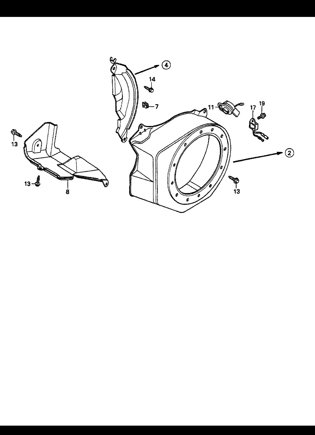
FAN COVER ASSY.
NO. PART NO. PART NAME QTY.REMARKS
2 19610ZE1000ZC COVER, FAN *NH1* (BLACK) 1
4 19612ZH8810 PLATE, SIDE (OIL ALERT) 1
7 90601ZH7013 CLIP, HARNESS 1
8 19630ZH8000 SHROUD 1
11 36100ZE1015 SWITCH ASSY., ENGINE STOP 1
11 36100ZH7003 SWITCH ASSY., ENGINE STOP 1
13 90013883000 BOLT, FLANGE (6 X 12) (CT200) 6
14 90022888010 BOLT, FLANGE (6 X 20) (CT200) 1
17 34150ZH7003 ALERT UNIT, OIL 1
19 957010600800 BOLT, FLANGE (6 X 8) 1
HONDA GX160K1TX2 ENGINE — FAN COVER ASSY.
PAGE 52 —STOW T-20H TRASH PUMP — PARTS MANUAL — REV. #0 (05/29/03)
FLYWHEEL ASSY.
HONDA GX160K1TX2 ENGINE — FLYWHEEL ASSY.

STOW T-20H TRASH PUMP — PARTS MANUAL— REV. #0 (05/29/03) — PAGE 53
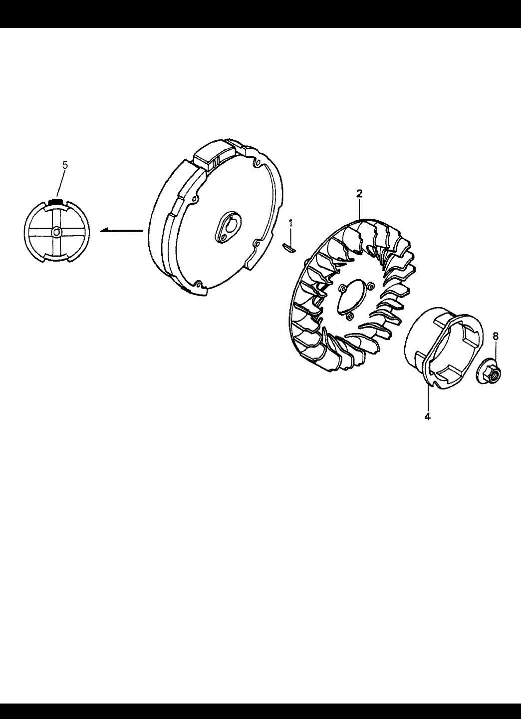
NO. PART NO. PART NAME QTY.REMARKS
1 13331357000 KEY, SPECIAL WOODRUFF (25 X 18) 1
2 19511ZE1000 FAN, COOLING 1
4 28451ZH8003 PULLEY, STARTER 1
5 31100ZE1010 FLYWHEEL 1
5 31100ZE1810 FLYWHEEL (LAMP) 1
8 90201878003 NUT, SPECIAL (14MM) 1
FLYWHEEL ASSY.
HONDA GX160K1TX2 ENGINE — FLYWHEEL ASSY.
PAGE 54 —STOW T-20H TRASH PUMP — PARTS MANUAL — REV. #0 (05/29/03)
FUEL TANK ASSY.
HONDA GX160K1TX2 ENGINE — FUEL TANK ASSY.

STOW T-20H TRASH PUMP — PARTS MANUAL— REV. #0 (05/29/03) — PAGE 55
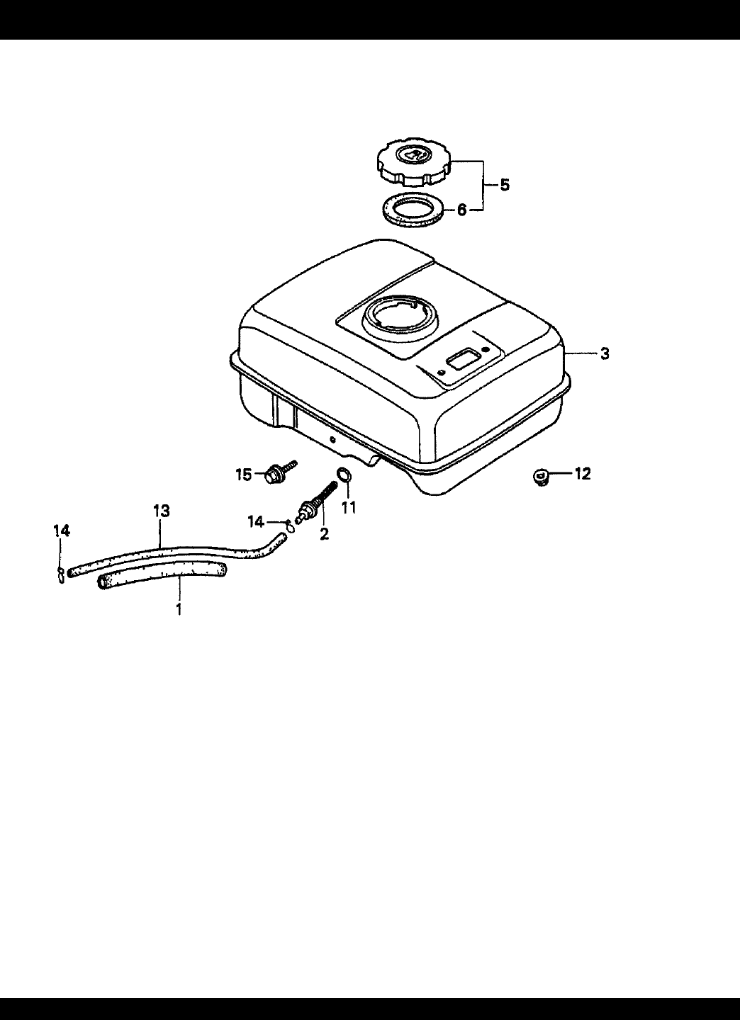
NO. PART NO. PART NAME QTY.REMARKS
1 16854ZH8000 RUBBER, SUPPORTER (107MM) 1
2 16955ZE1000 JOINT, FUEL TANK 1
3 17510ZE1020ZF TANK, FUEL *NH1* (BLACK) 1
5 17620ZH7023 CAP, FUEL FILLER ...................................... 1 ...... INCLUDES ITEMS W/*
6*17631ZH7003 GASKET, FUEL FILLER CAP 1
11 91353671003 O-RING (13.5 X 1.5) (ARAI) 1
12 9405006000 NUT, FLANGE (6MM) 2
13 950014500360M BULK HOSE, FUEL (4.5 X 3000) 1
(4.5 X 140)
14 9500202080 CLIP, TUBE (B8) 2
15 957010602500 BOLT, FLANGE (6 X 25) 1
FUEL TANK ASSY.
HONDA GX160K1TX2 ENGINE — FUEL TANK ASSY.
PAGE 56 —STOW T-20H TRASH PUMP — PARTS MANUAL — REV. #0 (05/29/03)
IGNITION COIL ASSY.
HONDA GX160K1TX2 ENGINE — IGNITION COIL ASSY.

STOW T-20H TRASH PUMP — PARTS MANUAL— REV. #0 (05/29/03) — PAGE 57
IGNITION COIL ASSY.
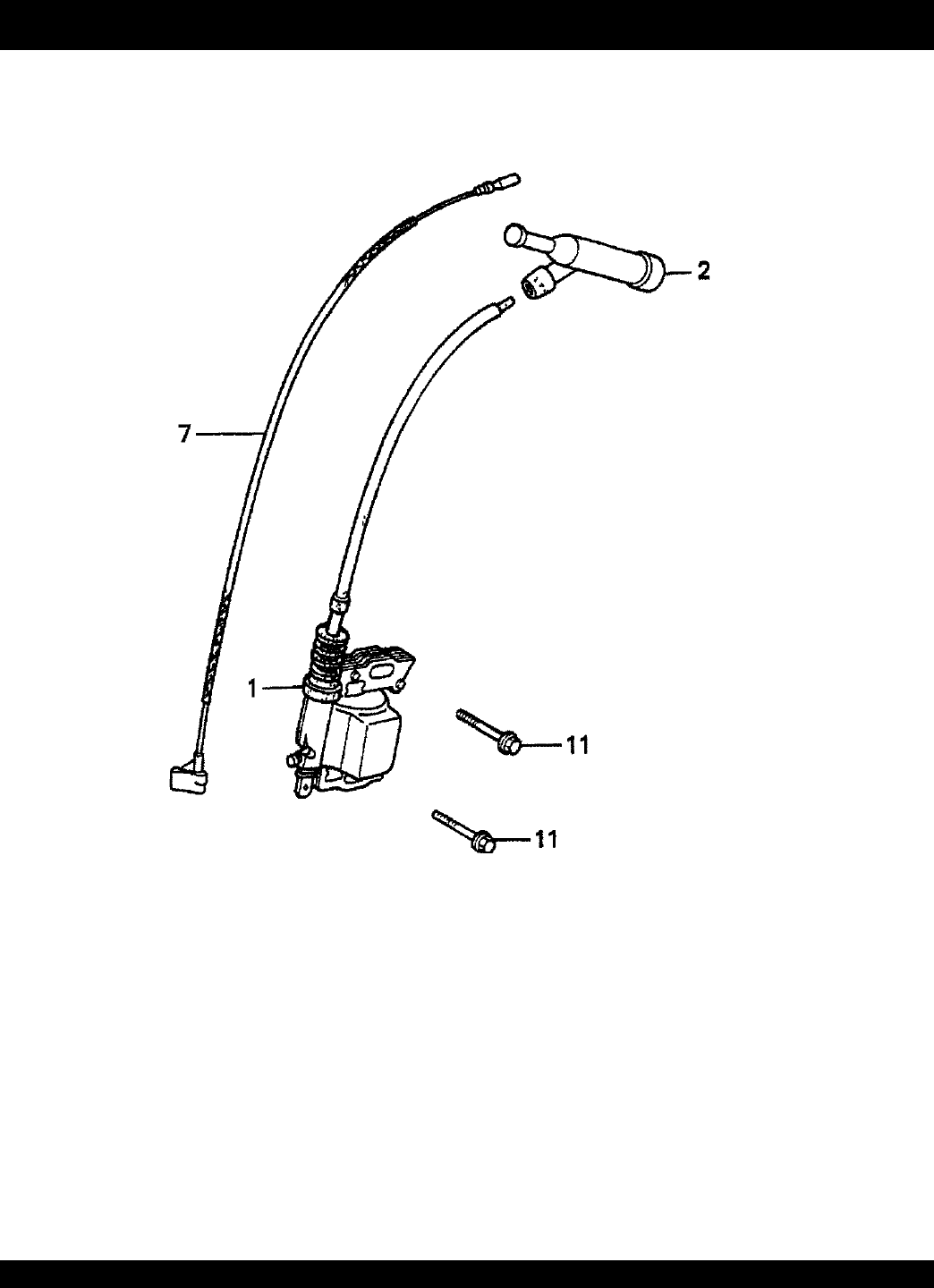
NO. PART NO. PART NAME QTY.REMARKS
1 30500ZE1033 COIL ASSY., IGNITION 1
2 30700ZE1013 CAP ASSY., NOISE SUPPRESSOR 1
7 36101ZE1010 WIRE, STOP SWITCH (370MM) 1
11 90121952000 BOLT, FLANGE (6 X 25) 2
HONDA GX160K1TX2 ENGINE — IGNITION COIL ASSY.
PAGE 58 —STOW T-20H TRASH PUMP — PARTS MANUAL — REV. #0 (05/29/03)
MUFFLER ASSY.
HONDA GX160K1TX2 ENGINE — MUFFLER ASSY.

STOW T-20H TRASH PUMP — PARTS MANUAL— REV. #0 (05/29/03) — PAGE 59
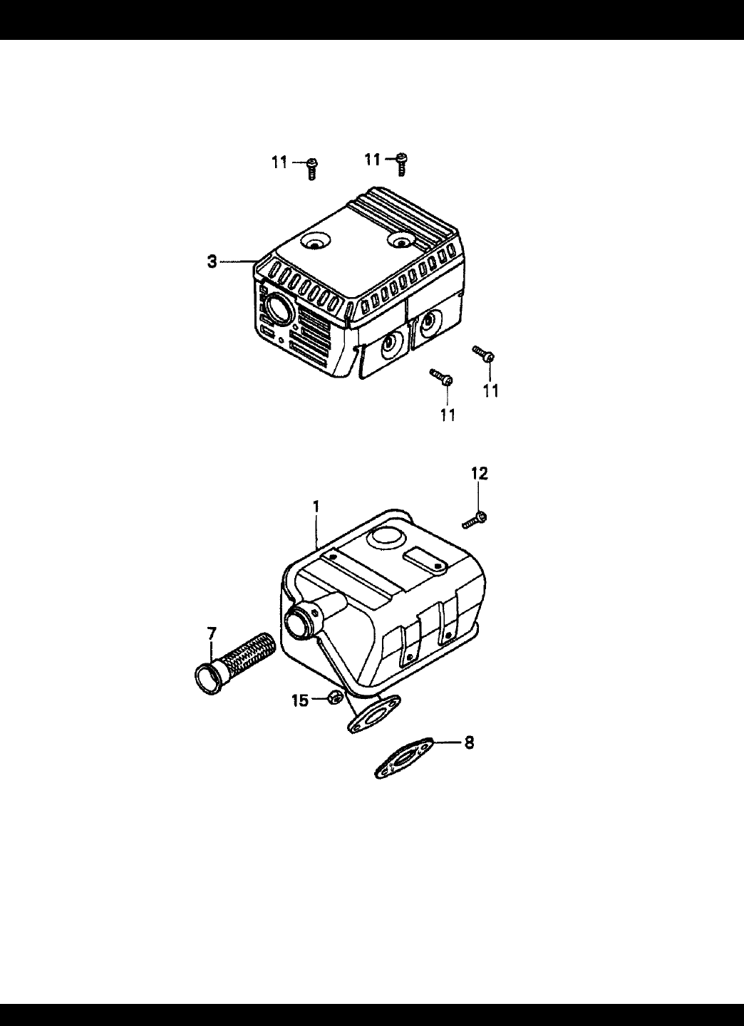
MUFFLER ASSY.
NO. PART NO. PART NAME QTY.REMARKS
1 18310ZF1000 MUFFLER 1
1 18310ZH8810 MUFFLER (OPTIONAL) 1
3 18320ZF1H01 PROTECTOR, MUFFLER 1
7 18355ZE1000 ARRESTER, SPARK (OPTIONAL) 1
8 18381ZH8800 GASKET, MUFFLER 1
11 90050ZE1000 SCREW, TAPPING (5 X 8) 4
12 90055ZE1000 SCREW, TAPPING (4 X 6) (OPTIONAL) 1
15 94001080000S NUT, HEX (8MM) 2
HONDA GX160K1TX2 ENGINE — MUFFLER ASSY.
PAGE 60 —STOW T-20H TRASH PUMP — PARTS MANUAL — REV. #0 (05/29/03)
PISTON ASSY.
HONDA GX160K1TX2 ENGINE — PISTON ASSY.

STOW T-20H TRASH PUMP — PARTS MANUAL— REV. #0 (05/29/03) — PAGE 61
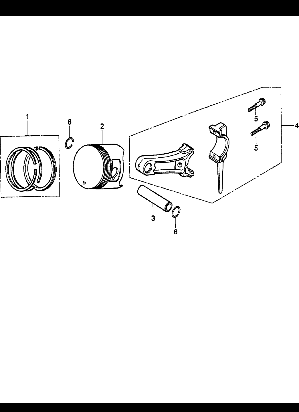
PISTON + RINGS ASSY.
NO. PART NO. PART NAME QTY.REMARKS
1 13010ZH8941 RING SET, PISTON (STD) 1
1 13011ZH8941 RING SET, PISTON (OS 0.25) 1
1 13012ZH8941 RING SET, PISTON (OS 0.50) 1
1 13013ZH8941 RING SET, PISTON (0.75) OPTION 1
2 13101ZH8000 PISTON (STD) 1
2 13102ZH8000 PISTON (OS 0.25) 1
2 13103ZH8000 PISTON (OS 0.50) 1
2 13104ZH8000 PISTON (0.75) 1
3 13111ZE1000 PIN, PISTON 1
4 132A0ZE1000 ROD ASSY., CONNECTING (US 0.25) 1 ......... INCLUDES ITEMS W/*
4 13200ZE1010 ROD ASSY., CONNECTING 1
5*90001ZE1000 BOLT, CONNECTING ROD 2
6 90551ZE1000 CLIP, PISTON PIN (18MM) 2
HONDA GX160K1TX2 ENGINE — PISTON ASSY.
PAGE 62 —STOW T-20H TRASH PUMP — PARTS MANUAL — REV. #0 (05/29/03)
RECOIL STARTER ASSY.
HONDA GX160K1TX2 ENGINE — RECOIL STARTER ASSY.

STOW T-20H TRASH PUMP — PARTS MANUAL— REV. #0 (05/29/03) — PAGE 63
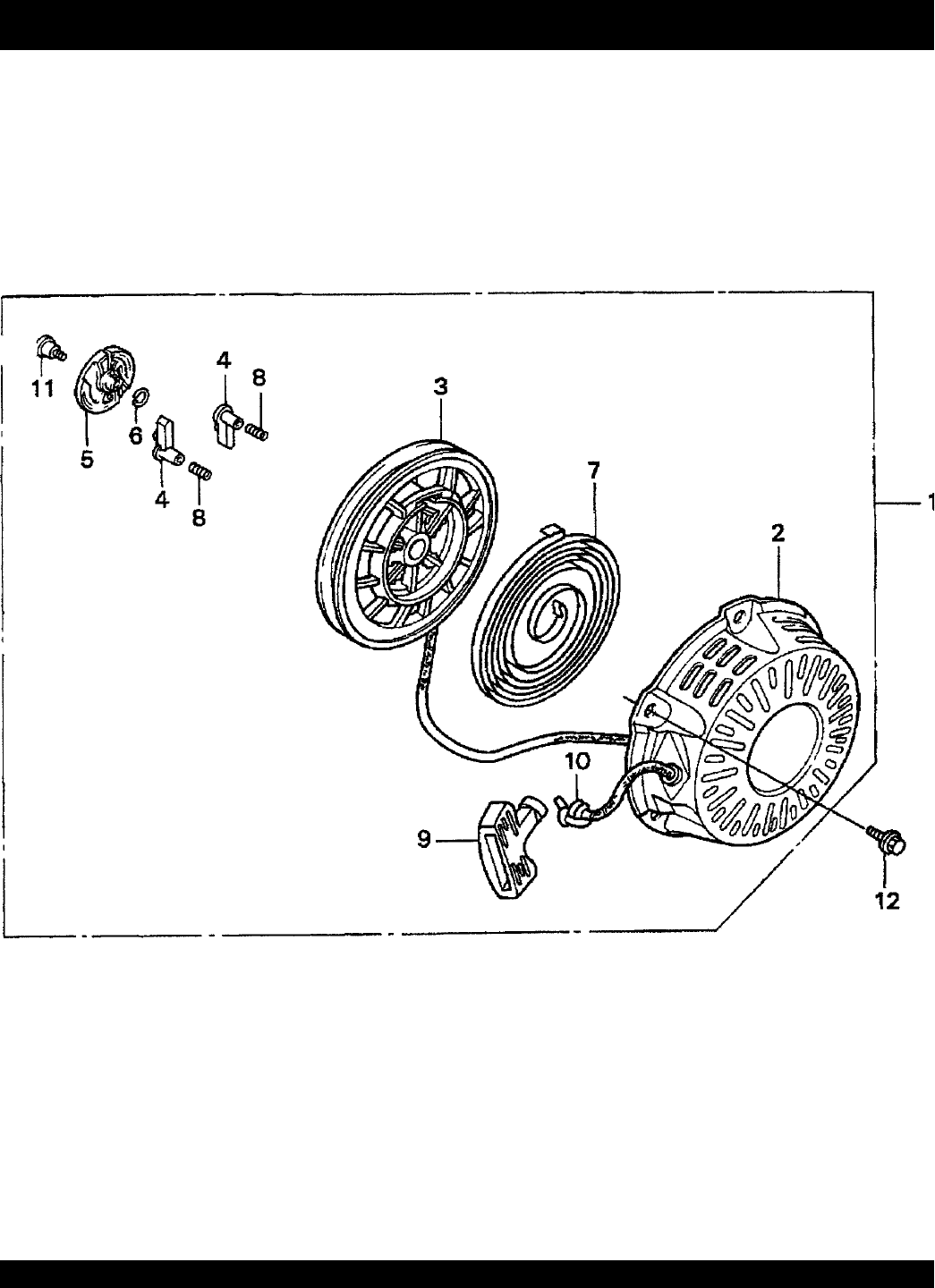
RECOIL STARTER ASSY.
NO. PART NO. PART NAME QTY.REMARKS
1 28400ZH8013ZB STARTER ASSY., RECOIL “NH1”(BLACK) ............ 1 ..... INCLUDES ITEMS W/*
2*28410ZH8003ZB CASE, RECOIL STARTER “NH1”(BLACK) 1
3*28420ZH8013 REEL, RECOIL STARTER 1
4*28422ZH8013 RATCHET, STARTER 2
5*28433ZH8003 GUIDE, RATCHET 1
6*28441ZH8003 SPRING, FRICTION 1
7*28442ZH8003 SPRING, RECOIL STARTER 1
8*28443ZH8003 SPRING, RETURN 2
9*28461ZH8003 KNOB, RECOIL STARTER 1
10*28462ZH8003 ROPE, RECOIL STARTER 1
11*90003ZH8003 SCREW, SETTING 1
12 90008ZE2003 BOLT, FLANGE (6 X 10) 3
HONDA GX160K1TX2 ENGINE — RECOIL STARTER ASSY.

PAGE 64 —STOW T-20H TRASH PUMP — PARTS MANUAL — REV. #0 (05/29/03)
NOTE PAGE

STOW T-20H TRASH PUMP — PARTS MANUAL— REV. #0 (05/29/03) — PAGE 65
HONDA GX160K1TX2 ENGINE — GASKET KIT ASSY.
GASKET KIT ASSY.
NO. PART NO. PART NAME QTY.REMARKS
1 06111ZH8405 GASKET KIT ............................................. 1 ...... INCLUDES ITEMS W/*
2*11381ZH8800 GASKET, CASE COVER 1
1*11381ZH8801 GASKET, CASE COVER 1
3*12251ZF1800 GASKET, CYLINDER HEAD 1
4*12391ZE1000 GASKET, CYLINDER HEAD COVER 1
5*16212ZH8800 GASKET, INSULATOR 1
6*16221ZH8801 GASKET, CARBURETOR 1
7*18381ZH8800 GASKET, MUFFLER 1
PAGE 66 —STOW T-20H TRASH PUMP — PARTS MANUAL — REV. #0 (05/29/03)
HONDA GX160K1TX2 ENGINE — LABELS ASSY.
LABELS ASSY.

STOW T-20H TRASH PUMP — PARTS MANUAL— REV. #0 (05/29/03) — PAGE 67
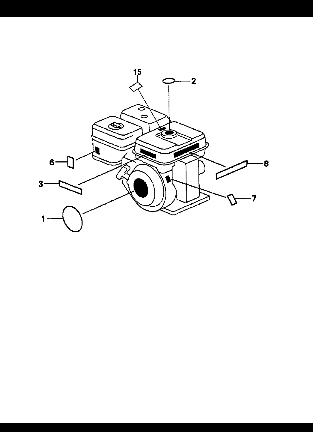
LABELS ASSY.
NO. PART NO. PART NAME QTY.REMARKS
1 87521ZH8020 EMBLEM (5.5) 1
2 87522ZE1810 MARK, CAUTION (EXTERNAL) 1
3 87522ZH9000 LABEL, CAUTION 1
6 87528ZE1810 MARK, CHOKE 1
7 87530ZH8810 LABEL, SPECIFICATION (EXT.) 1
8 87532ZH8810 MARK, OIL ALERT (E) 1
15 87586ZH7W00 LABEL, FUEL CAUTION 1
HONDA GX160K1TX2 ENGINE — LABELS ASSY.

PAGE 68 —STOW T-20H TRASH PUMP — PARTS MANUAL — REV. #0 (05/29/03)
Multiquip reserves the right to quote and sell
direct to Government agencies, and to Original
Equipment Manufacturer accounts who use
our products as integral parts of their own
products.
SPECIAL EXPEDITING SERVICE
A $35.00 surcharge will be added to the invoice
for special handling including bus shipments,
insured parcel post or in cases where Multiquip
must personally deliver the parts to the carrier.
LIMITATIONS OF SELLER’S LIABILITY
Multiquip shall not be liable hereunder for
damages in excess of the purchase price of the
item with respect to which damages are
claimed, and in no event shall Multiquip be
liable for loss of profit or good will or for any
other special, consequential or incidental dam-
ages.
LIMITATION OF WARRANTIES
No warranties, express or implied, are made
in connection with the sale of parts or trade
accessories nor as to any engine not manufac-
tured by Multiquip. Such warranties made in
connection with the sale of new, complete units
are made exclusively by a statement of war-
ranty packaged with such units, and Multiquip
neither assumes nor authorizes any person to
assume for it any other obligation or liability
whatever in connection with the sale of its
products. Apart from such written statement of
warranty, there are no warranties, express,
implied or statutory, which extend beyond the
description of the products on the face hereof.
5. Parts must be in new and resalable con-
dition, in the original Multiquip package (if
any), and with Multiquip part numbers
clearly marked.
6. The following items are not returnable:
a. Obsolete parts. (If an item is in the
price book and shows as being re-
placed by another item, it is obsolete.)
b. Any parts with a limited shelf life
(such as gaskets, seals, “O” rings,
and other rubber parts) that were pur-
chased more than six months prior to
the return date.
c. Any line item with an extended dealer
net price of less than $5.00.
d. Special order items.
e. Electrical components.
f. Paint, chemicals, and lubricants.
g. Decals and paper products.
h. Items purchased in kits.
7. The sender will be notified of any material
received that is not acceptable.
8. Such material will be held for five working
days from notification, pending instruc-
tions. If a reply is not received within five
days, the material will be returned to the
sender at his expense.
9. Credit on returned parts will be issued at
dealer net price at time of the original
purchase, less a 15% restocking charge.
10. In cases where an item is accepted, for
which the original purchase document
can not be determined, the price will be
based on the list price that was effective
twelve months prior to the RMA date.
11. Credit issued will be applied to future
purchases only.
PRICING AND REBATES
Prices are subject to change without prior
notice. Price changes are effective on a spe-
cific date and all orders received on or after that
date will be billed at the revised price. Rebates
for price declines and added charges for price
increases will not be made for stock on hand
at the time of any price change.
PAYMENT TERMS
Terms of payment for parts are net 10 days.
FREIGHT POLICY
All parts orders will be shipped collect or
prepaid with the charges added to the invoice.
All shipments are F.O.B. point of origin.
Multiquip’s responsibility ceases when a signed
manifest has been obtained from the carrier,
and any claim for shortage or damage must be
settled between the consignee and the carrier.
MINIMUM ORDER
The minimum charge for orders from Mul-
tiquip is $15.00 net. Customers will be asked
for instructions regarding handling of orders
not meeting this requirement.
RETURNED GOODS POLICY
Return shipments will be accepted and credit
will be allowed, subject to the following provi-
sions:
1. A Returned Material Authorization must
be approved by Multiquip prior to ship-
ment.
2. To obtain a Return Material Authorization,
a list must be provided to Multiquip Parts
Sales that defines item numbers, quanti-
ties, and descriptions of the items to be
returned.
a. The parts numbers and descriptions
must match the current parts price
list.
b. The list must be typed or computer
generated.
c. The list must state the reason(s) for
the return.
d. The list must reference the sales
order(s) or invoice(s) under which the
items were originally purchased.
e. The list must include the name and
phone number of the person request-
ing the RMA.
3. A copy of the Return Material Authoriza-
tion must accompany the return shipment.
4. Freight is at the sender’s expense. All
parts must be returned freight prepaid to
Multiquip’s designated receiving point.
Effective: October 1, 2002 TERMS AND CONDITIONS OF SALE — PARTS

STOW T-20H TRASH PUMP — PARTS MANUAL— REV. #0 (05/29/03) — PAGE 69
NOTE PAGE

OPERATION AND PARTS MANUAL
PARTS DEPARTMENT:
800-427-1244
FAX: 800-672-7877
SERVICE DEPARTMENT/TECHNICAL ASSISTANCE:
800-478-1244
FAX: 310-631-5032
STOW CONSTRUCTION EQUIPMENTSTOW CONSTRUCTION EQUIPMENT
STOW CONSTRUCTION EQUIPMENTSTOW CONSTRUCTION EQUIPMENT
STOW CONSTRUCTION EQUIPMENT
A DIVISION OF MULTIQUIP INC.
POST OFFICE BOX 6254
CARSON, CA 90749
310-537-3700 • 888-252-STOW [888-252-7869]
FAX: 310-537-1986 • FAX: 800-556-1986
E-MAIL: stow@multiquip.com • WWW: stowmfg.com
HERE'S HOW TO GET HELP
PLEASE HAVE THE MODEL AND SERIAL
NUMBER ON-HAND WHEN CALLING
PARTS DEPARTMENT
800-427-1244 or 310-537-3700
FAX: 800-672-7877 or 310-637-3284
SERVICE DEPARTMENT
800-421-1244
FAX: 310- 537-4259
TECHNICAL ASSISTANCE
800-478-1244
FAX: 310- 631-5032
WARRANTY DEPARTMENT
888-661-4279, or 310-661-4279
FAX: 310- 537-1173
