Stow Ms 40M Users Manual MS40MSTOWREV0.p65
MS-40M to the manual 2a6353b6-849d-4e13-8811-5c7bb49cd77c
2015-02-02
: Stow Stow-Ms-40M-Users-Manual-489450 stow-ms-40m-users-manual-489450 stow pdf
Open the PDF directly: View PDF ![]() .
.
Page Count: 46

© COPYRIGHT 2002, MULTIQUIP INC.
PARTS AND OPERATION MANUAL
PLASTER/MORTAR MIXERS
MS-40M
(Steel-Drum Mechanical)
Revision #1 (05/17/02)
STOW
A DIVISION OF MULTIQUIP INC.
STOW CONSTRUCTION EQUIPMENT PARTS DEPARTMENT:
A DIVISION OF MULTIQUIP INC.
800-427-1244
POST OFFICE BOX 6254 FAX: 800-672-7877
CARSON, CALIFORNIA 90749
SERVICE DEPARTMENT/TECHNICAL ASSISTANCE:
310-537-3700 • 888-252-STOW [888-252-7869] 800-478-1244
FAX: 310-537-1986 • FAX: 800-556-1986 FAX: 310-631-5032
E-MAIL: stow@multiquip.com • WWW: stowmfg.com
A DIVISION OF MULTIQUIP INC.

PAGE 2 — STOW MS-40M— PARTS & OPERATION MANUAL — REV. #1 (05/17/02)

STOW MS-40M — PARTS & OPERATION MANUAL — REV. #1 (05/17/02) — PAGE 3
HERE'S HOW TO GET HELP
PLEASE HAVE THE MODEL AND SERIAL NUMBER
ON-HAND WHEN CALLING
PARTS DEPARTMENT
800-427-1244 or 310-537-3700
FAX: 800-672-7877 or 310-637-3284
SERVICE DEPARTMENT/TECHNICAL ASSISTANCE
800-478-1244 or 310-537-3700
FAX: 310- 537-4259
WARRANTY DEPARTMENT
888-661-4279, or 310-661-4279
FAX: 310- 537-1173
MAIN
800-421-1244 or 310-537-3700
FAX: 310-537-3927

PAGE 4 — STOW MS-40M— PARTS & OPERATION MANUAL — REV. #1 (05/17/02)
TABLE OF CONTENTS
Here's How To Get Help ........................................... 3
Table Of Contents .................................................... 4
Parts Ordering Procedures ...................................... 5
Operation and Safety Decals ................................... 6
Rules For Safe Operation .....................................7-8
Specifications ........................................................... 9
General Information ............................................... 10
MQ STOW — Plaster/ Mortar
Mixer
Controls .................................................................. 11
Electric Motor ......................................................... 12
Towing .................................................................... 13
Paddle Blade Adjustment ..................................14-15
Initial Start-Up ...................................................16-17
Maintenance .....................................................18-19
Troubleshooting (Engine) ....................................... 20
Troubleshooting (Engine/Mixer) ............................. 21
Explanation Of Codes In Remarks Column ........... 22
Suggested Spare Parts .......................................... 23
Engine Side Paddle Assembly ..........................24-25
Tow Side Paddle Assembly ...............................26-27
Paddle Shaft Assembly .....................................28-29
Steel Drum Assembly........................................30-31
Cab Assembly ...................................................32-33
Frame, Wheel, Tire and Hub Assembly ............34-35
Name Plate and Decals ....................................36-37
Engines
Honda Engine Assembly ...................................38-39
Motor
Electric Motor Assembly....................................40-41
Transmissions
Transmission Assembly.....................................42-43
Terms and Conditions Of Sale — Parts ................. 44
NOTE
Specification and part number
are subject to change without
notice.

STOW MS-40M — PARTS & OPERATION MANUAL — REV. #1 (05/17/02) — PAGE 5
PARTS ORDERING PROCEDURES
Extra Fax DiscountExtra Fax Discount
Extra Fax DiscountExtra Fax Discount
Extra Fax Discount
for Domestic USAfor Domestic USA
for Domestic USAfor Domestic USA
for Domestic USA
Dealers OnlyDealers Only
Dealers OnlyDealers Only
Dealers Only
Get special freight allowances
when you order 10 or more
line items via FAX!**
UPS Ground Service at no charge for freight
PS Third Day Service at one-half of actual freight cost
No other allowances on freight shipped by any other carrier.
**Common nuts, bolts and washers (all items under $1.00 list price)
do not count towards the 10+ line items.
*DISCOUNTS ARE SUBJECT TO CHANGE*
Fax order discount and UPS special programs revised June 1, 1995
Earn Extra Discounts when
you order by FAX!
All parts orders which include complete part numbers
and are received by fax qualify for the following extra
discounts:
Number of
line items ordered Additional Discount
1-9 items 3%
10+ items** 5%
Now! Direct TOLL-FREE access
to our Parts Department!
Toll-free nationwide:
800-421-1244
Toll-free FAX:
800/6-PARTS-7 • 800-672-7877
Dealer account number
Dealer name and address
Shipping address (if different than billing address)
Return fax number
Applicable model number
Quantity, part number and description of each part
Specify preferred method of shipment:
•UPS Ground
•UPS Second Day or Third Day*
•UPS Next Day*
•Federal Express Priority One (please provide us with your Federal
Express account number)*
•Airborne Express*
•Truck or parcel post
*Normally shipped the same day the order is received, if prior to 2PM west coast time.
PAGE 6 — STOW MS-40M— PARTS & OPERATION MANUAL — REV. #1 (05/17/02)
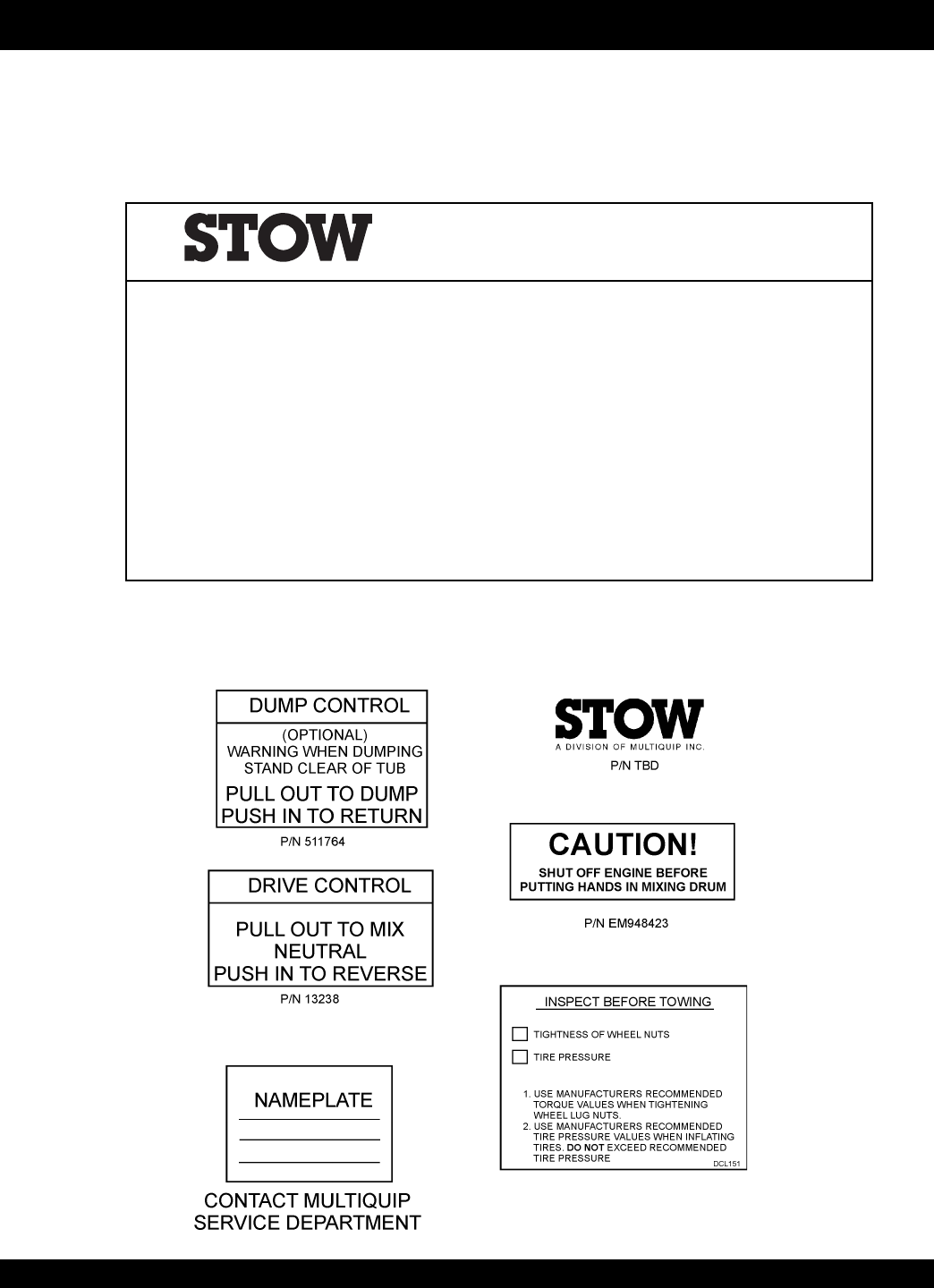
OPERATION AND SAFETY DECALS
Machine Safety Decals
This STOW mixer is equipped with a number of safety decals. These decals are provided for operator safety and maintenance
information. The illustration below shows these decals as they appear on the mixer. Should any of these decals become unreadable,
replacements can be obtained from your dealer.
STOW CONCRETE PRODUCTS — A MULTIQUIP COMPANY — CARSON, CALIFORNIA
P/N 924801
SAFETY INSTRUCTIONS
1. Read owners manuals before operating.
2. Keep unauthorized and untrained people away from machine during operation.
3. Make sure all safety devices are in place before this machine is started.
4. Make sure engine is turned off and spark plug wire is disconnected before cleaning the
machine.
5. Keep hands and fingers away from moving objects.
6. Do not operate machine in an enclosed area. Proper ventilation is required.
7. Never leave machine unattended when operating.
8. Always stop engine and allow engine to cool before adding fuel or oil.
A DIVISION OF MULTIQUIP INC.
STOW MS-40M — PARTS & OPERATION MANUAL — REV. #1 (05/17/02) — PAGE 7
CAUTION:
Failure to follow instructions in this manual may
lead to serious injury or even death! This
equipment is to be operated by trained and
qualified personnel only! This equipment is for
industrial use only.
The following safety guidelines should always be used when
operating the MS-40M mixer:
GENERAL SAFETY
■
DO NOT operate or service this equipment
before reading this entire manual.
■
This equipment should not be operated by persons under 18
years of age.
■
NEVER operate this equipment without proper
protective clothing, shatterproof glasses, steel-
toed boots and other protective devices required
by the job.
■
NEVER operate this equipment when not
feeling well due to fatigue, illness or taking
medicine.
■
NEVER operate this equipment under the
influence or drugs or alcohol.
■
NEVER use accessories or attachments, which are not
recommended by Multiquip for this equipment. Damage to
the equipment and/or injury to user may result.
■
Manufacture does not assume responsibility for any accident
due to equipment modifications.
■
Whenever necessary, replace nameplate, operation and
safety decals when they become difficult read.
■
Always check the machine for loosened threads or bolts before
starting.
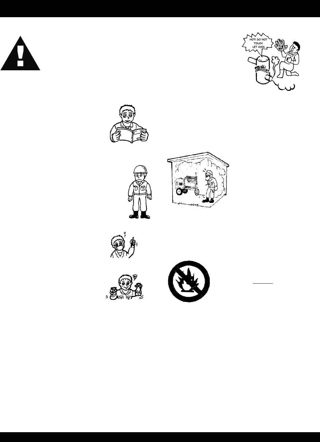
RULES FOR SAFE OPERATION
■
Always refuel in a well-ventilated area, away from sparks and
open flames.
■
Always use extreme caution when
working with flammable liquids. When
refueling, stop the engine and allow it to
cool. DO NOT smoke around or near the
machine. Fire or explosion could result
from fuel vapors, or if fuel is spilled on a
hot engine.
■
NEVER operate the mixer in an explosive atmosphere or near
combustible materials. An explosion or fire could result
causing severe
bodily harm or even death.
■
NEVER touch the hot exhaust manifold, muffler or cylinder. Allow
these parts to cool before
servicing engine or mixer.
■
The engine section of this mixer requires an adequate free
flow of cooling air. Never operate the mixer in any enclosed or
narrow area where free flow of the
air is restricted. If the air flow is
restricted it will cause serious
damage to the mixer or engine and
may cause injury to people.
Remember the mixer's engine
gives off DEADLY carbon
monoxide gas.
■
High Temperatures – Allow the engine to cool before adding
fuel or performing service and maintenance functions. Contact
with
hot
components can cause serious burns.

PAGE 8 — STOW MS-40M— PARTS & OPERATION MANUAL — REV. #1 (05/17/02)
CAUTION:
Failure to follow instructions in this manual may
lead to serious injury or even death! This
equipment is to be operated by trained and
qualified personnel only! This equipment is for
industrial use only.
The following safety guidelines should always be used when
operating the MS-40MSM mixer:
GENERAL SAFETY
■
Stop the engine when leaving the mixer unattended.
■
Block the unit when leaving or when using on a slope.
■
Maintain this equipment in a safe operating condition at all
times.
■
Always stop the engine before servicing, adding fuel and oil.
■
NEVER Run engine without air filter. Severe engine may
occur.
■
Always service air cleaner frequently to prevent carburetor
malfunction.
■
Always be sure the operator is familiar with proper safety
precautions and operations techniques before using mixer.
■
Always store equipment properly when it is not being used.
Equipment should be stored in a clean, dry location out of the
reach of children.
■
NEVER use accessories or attachments, which are not
recommended by Multiquip for this equipment. Damage to
the equipment and/or injury to user may result.
■
NEVER Run engine without air cleaner. Severe engine
damage may occur.
■
Always read, understand, and follow procedures in Operator’s
Manual before attempting to operate equipment.
■
Always be sure the operator is familiar with proper safety
precautions and operations techniques before using pump.
■
Always store equipment properly when it is not being used.
Equipment should be stored in a clean, dry location out of the
reach of children.
■
Caution must be exercised while servicing this equipment.
Rotating and moving parts can cause injury if contacted.
■
When towing, an adequate safety chain must be fastened to
the frame, refer to page 14.
■
Keep all inexperienced and unauthorized people away from
the equipment at all times.
■
Unauthorized equipment modifications will void all warranties.
■
Check all fasteners periodically for tightness. Also check
towing tongue bolt, lock nut and wheel lug nuts for wear.
■
Stop the engine and disconnect the spark plug before allowing
anybody’s hands in the mixing drum.
■
Never pour or spray water over the engine or electric motor.
■
Always stand clear of dump handle when mixer is in operation.
Any binding of material between the mixer blades and drum
will cause drum and handle to quickly move in the discharge
position.
■
Depending on type of mixer, test the
ON/OFF
switch for either
the gasoline engine or electric motor before operating. The
purpose of these switches is to shut down the engine or motor
of the mixer.
Emergencies
■
Always know the location of the nearest
fire extinguisher
and
first aid kit
. Know the location of the nearest telephone.
Also know the phone numbers of the nearest
ambulance
,
doctor
and
fire department
. This information will be
invaluable in the case of an emergency.
Maintenance Safety
■
NEVER lubricate components or attempt service on a running
machine.
■
Always allow the machine a proper amount of time to cool
before servicing.
■
Keep the machinery in proper running condition.
■
Fix damage to the machine immediately and always replace
broken parts.
■
Dispose of hazardous waste properly. Examples of potentially
hazardous waste are used motor oil, fuel and fuel filters.
■
DO NOT use food or plastic containers to dispose of
hazardous waste. Emergencies
■
Always know the location of the nearest
fire extinguisher
and
first aid kit
. Know the location of the nearest telephone.
Also know the phone numbers of the nearest
ambulance
,
doctor
and
fire department
. This information will be
invaluable in the case of an emergency.
CAUTION:
■
DO NOT operate this equipment unless all
guards and safety devices are attached and in
place.
RULES FOR SAFE OPERATION

STOW MS-40M — PARTS & OPERATION MANUAL — REV. #1 (05/17/02) — PAGE 9
MS-40M — SPECIFICATIONS
NOTE
In accordance with our established policy of constant
improvement, we reserve the right to amend these
specifications at any time without notice.
rexiMlacinahceMM04-SM.1elbaT
)sretil(tf.uc-yticapaC)043(21
sgab-yticapacgaB4ot5.3
).gk(sbl-thgieW)494(090,1
).mc(.ni-HxWxraBwoT/whtgneL )251x031x802(06x15x28
).mc(ni-eldnaHpmuD/WthgieH)191(57
).mc(ni-thgieHegrahcsiD)191(57
evirDlacinahceM
noitcApmuDlaunaM
secruoSrewoP
064/032esahP-elgniSPH5 cirtcelE cirtcelE064/032esahP-eerhTPH5 adnoHPH11

PAGE 10 — STOW MS-40M— PARTS & OPERATION MANUAL — REV. #1 (05/17/02)
MS-40M — GENERAL INFORMATION
GENERAL
The STOW MS-40M plaster and mortar mixer is shipped
completely assembled and has been factory tested.
The drum batch capacity of these mixers is between 3.5 and
4.0 bags. With proper care, they will give continuous service
year-after-year.
This mixer can be powered by either gasoline or electric motors.
The power from the engine is transmitted via the clutch/
reduction assembly directly to the paddle shaft. Therefore
providing high mixer torque and eliminating V-belts .
BEFORE STARTING
Before starting the engine, read the engine owners manual
and thoroughly understand the safety information.
Check the items listed below:
OIL LEVELS
Be sure to check the oil levels in the engine and engine reduction
unit before starting the unit.
HARDWARE
Check all hardware on the mixer before starting. Periodically
inspect all hardware. Loose hardware can contribute to early
component failure and poor performance. Use the torque chart
below as a general guideline and keep all hardware tight:
HARDWARE DIA TORQUE (LB./FT.)
5/16"- 18 24
3/8" - 24 37
1/2" - 13 39
1/2" - 13 (Grade 8) 90
GASOLINE ENGINE CARE
For care and operation of the gasoline engine, refer to the
engine manufacturer’s operating instructions furnished with the
engine. We recommend draining and refilling the engine
crankcase at least every thirty hours of operation. Check the
engine oil level daily.
GASOLINE MIXER OFF/ON SWITCH
This feature is on gasoline engine mixers only. Located on the
side of the engine cover. The purpose of this switch is to start
and stop the mixer in normal operation.
ELECTRIC MOTOR MIXER OFF/ON SWITCH
This feature is on electric motor mixers only. This switch is located
on top of the motor. Lift the engine cover to gain access to this
switch. The purpose of this switch is to start and stop the mixer
in normal operation. Never use the electric motor in an explosive
environment.
ENGINE THROTTLE AND CHOKE CONTROLS
Please refer to the engine owners manual for specific
instructions.
STOW MS-40M — PARTS & OPERATION MANUAL — REV. #1 (05/17/02) — PAGE 11
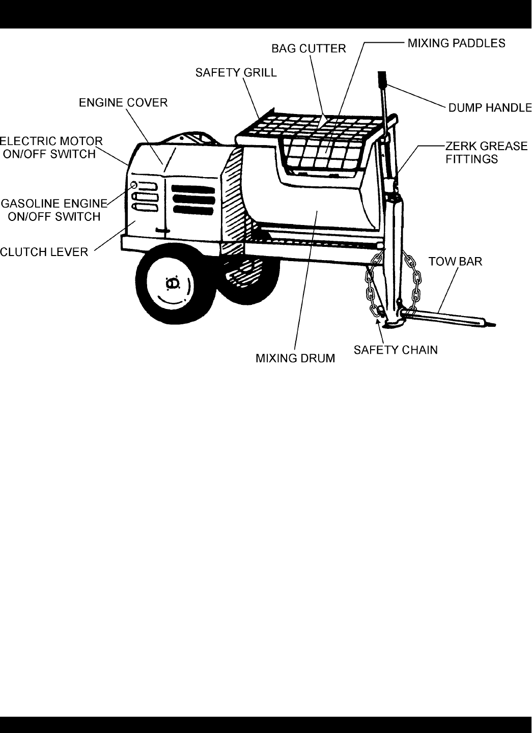
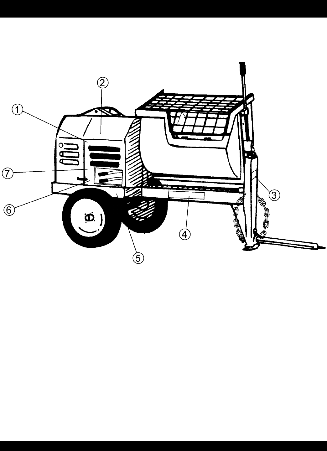
MS-40M — CONTROLS
Safety Grill — Provided for operator safety. This safety grill is
designed to keep hands and solid objects out of the mixing drum
when in use. This grill should be closed at all times when mixer
is in use. DO NOT remove the grill or grill opening bar. Keep the
grill clean by washing it down daily.
Bag Cutter— This feature allows compound mixing bags to be
opened easily, therefore allowing the contents of the bag to fall
directly into the mixing drum.
Mixing Paddles — Used in the mixing of material. This unit
uses four different types of paddles to provide a fast uniform mix.
Dump Handle — Pull this handle downward to dump the contents
of the drum. Push the handle upward to return the drum to its
vertical position.
Zerk Fitting — There is, on each end of the mixing drum a zerk
grease fitting. These fittings lubricate the dumping mechanism.
Lubricate both fittings at least twice a week.
Mixing Drum — Made of
steel
. Mixing materials such as
concrete, mortar, plaster are to be placed into this drum for
mixing. Always clean the drum after each use.
Tow Bar — When towing is required, connect tow bar to a
vehicle Reference page 14.
Engine Cover — Lift this cover to gain access to the engine
compartment.
ON/OFF Switch (gasoline) — This switch is provided on
mixers
with gasoline
engines only and is located on the side of the
engine cover. When activated it will shut down the engine.
ON/OFF Switch (electric) — This switch is provided on mixers
with electric motors. To gain access to this switch, lift the engine
cover. When activated it will shut down the electric motor.
Clutch Lever — Push the clutch lever forward, toward the tow
tongue end of the mixer to engage clutch. Once clutch is
engaged paddle shaft will rotate. To disengage clutch pull the
clutch backwards towards the engine.
Figure 1. Mixer
PAGE 12 — STOW MS-40M— PARTS & OPERATION MANUAL — REV. #1 (05/17/02)
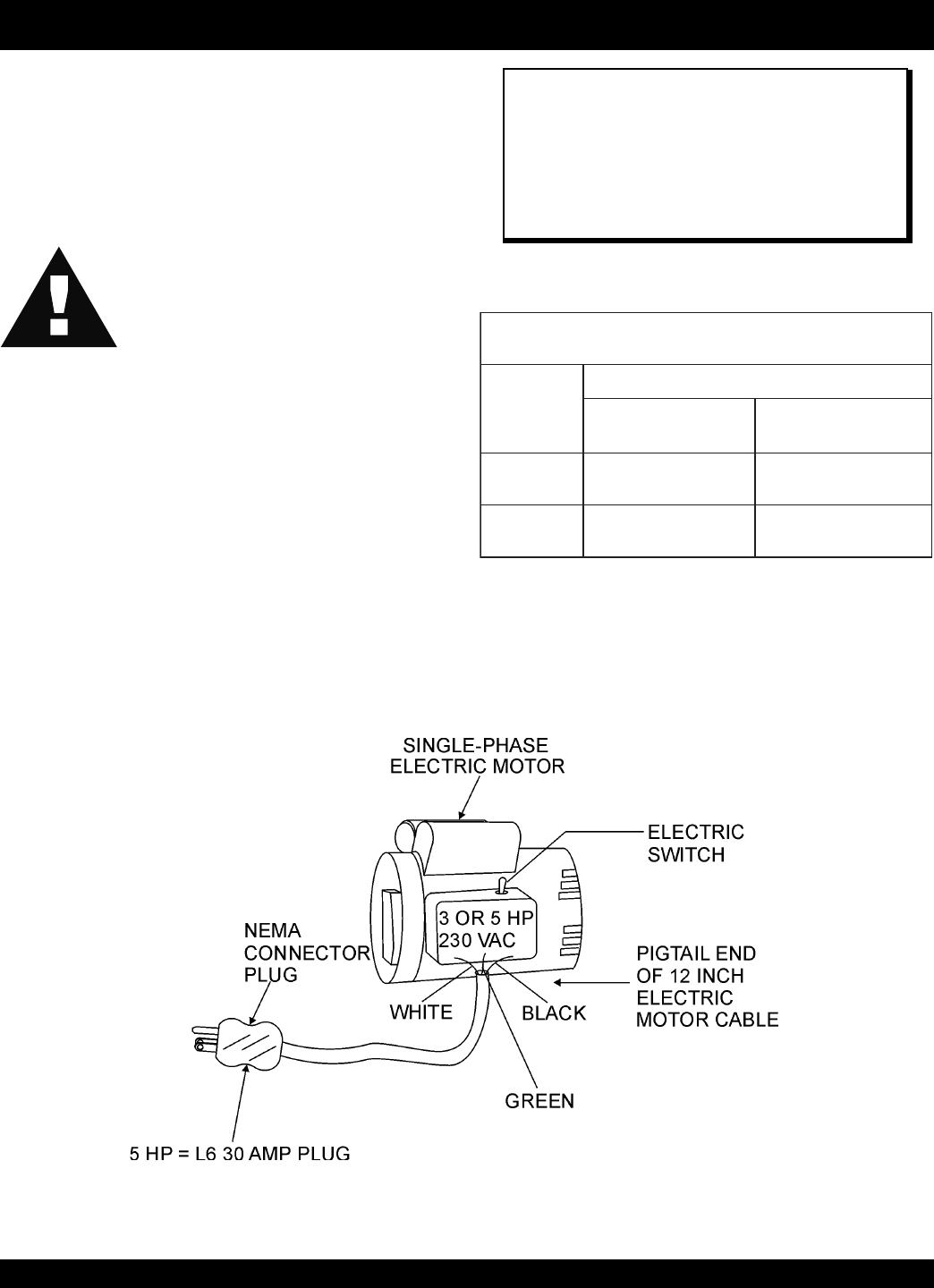
MS-40M — ELECTRIC MOTOR
ELECTRIC MOTOR
For lubrication care and operation of the electric motor, refer to
your electric motor instruction booklet furnished with the motor.
Protect the electric motor from dust as much as possible and
keep ventilating openings clean.
The electric motor for this mixer is available in either a 5 HP
single-phase or 5 HP 3-phase configuration. The input voltage
requirement for these motors is either 230 VAC or 440 VAC only.
ELECTRIC MOTOR CONNECTION
A 12 inch electrical cable (Figure 2) with a pigtail at one end is
provided with the electrical motor for hookup to a power source.
Table 1. shows the required NEMA connector for the desired
motor horsepower rating. In addition, Table 2 also shows the
matching NEMA approved connector for the required extension
cord.
CAUTION:
■
DO NOT spray water at any time on the
electric motor
.
■
DO NOT operate electric motor in a
explosive environment.
NOTE
It is strongly recommended that all electrical wiring be
done by a
licensed electrician
. Special attention
should be given to the electric switch as well as the
over-and-under voltage protection devices as per
regulations set forth in the local electrical safety code
handbook.
Figure 2. Single Phase Electric Motor with 12 inch Pigtail Cable
noitamrofnIgniriWrotoMcirtcelE.2elbaT
rotoM rewopesroH gnitaR
esahPelgniS-tloV032
rotcennoCgulPAMENAMENgnitaM
rotcennoCelcatpeceR
PH3935049N/PP02-6L045049N/PR02-6L
PH5745049N/PP03-6L845049N/PR03-6L
STOW MS-40M — PARTS & OPERATION MANUAL — REV. #1 (05/17/02) — PAGE 13
MS-40M — TOWING
NOTE
Before towing, check with local and state laws for proper
compliance.
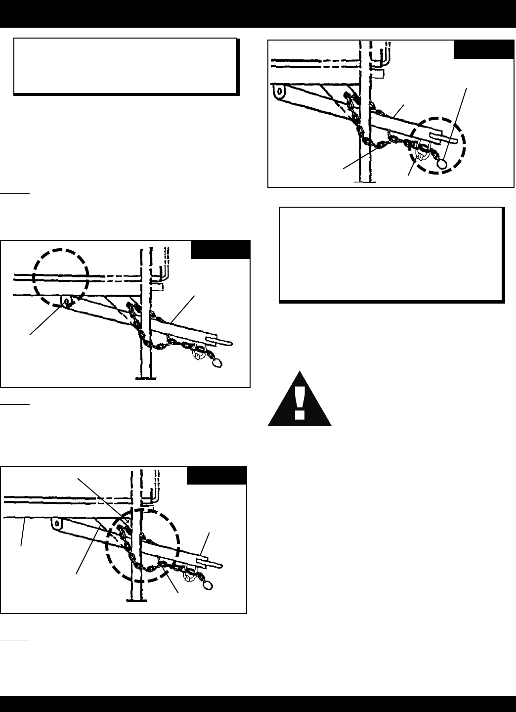
The tow bar and chain must be properly attached to the mixer
and towing vehicle prior to towing. Refer to the following
installation instruction:
Step 1.
Insert the Draw Bar into the main frame. Secure, utilizing the 3/4"
bolt (grade 5) and nylock nut. Tighten to 100 foot pounds.
DRAW BAR
BOLT & NUT
STEP 1
CONNECTOR LINK
FRAME ANGLE
FRAME GUSSET
INSERT CHAIN THROUGH
THE HOLE
STEP 2
DRAW BAR
Step 2.
Install the chain through the hole located between the frame
gusset and frame angle. Loop the chain together and place under
the Draw Bar. Secure with connector link.
VEHICLE
CONNECTOR LINK
DRAW BAR
BOTTOM CONNECTOR LINK
REMOVE EXCESS
CHAIN (SLACK)
STEP 3
NOTE
It is critical that the length of the chain be properly
adjusted, to prevent the
Draw Bar
and the front mixer
stand from dropping to the ground (contact) in the event
the Draw Bar becomes disconnected from the towing
vehicle.
If a new safety chain is required use P/N 13363. For a new
connector link use P/N 01004.
Step 3.
Extend the chain along the length of the Draw Bar, remove excess
chain (slack) and secure to bottom connector link. Secure the
chain to the towing vehicle, using the connector link.
CAUTION:
■
Check the following before towing:
BALL HITCH COUPLER
1. Check vehicle hitch, ball, and coupler for signs of wear or
damage. Replace any parts that are worn or damaged
before towing.
2. Use only the 2" ball diameter as indicated on your coupler.
Use of any other ball diameter will create an extremely
dangerous condition which can result in separation of the
coupler and ball or ball failure.
3. Be sure the coupler is secured to the hitch ball and the lock
lever is down tight and locked.
Recheck tightness again after towing about 50 miles.
4. Check that trailer safety chains are properly connected.
PAGE 14 — STOW MS-40M— PARTS & OPERATION MANUAL — REV. #1 (05/17/02)
MS-40M — PADDLE BLADE ADJUSTMENT
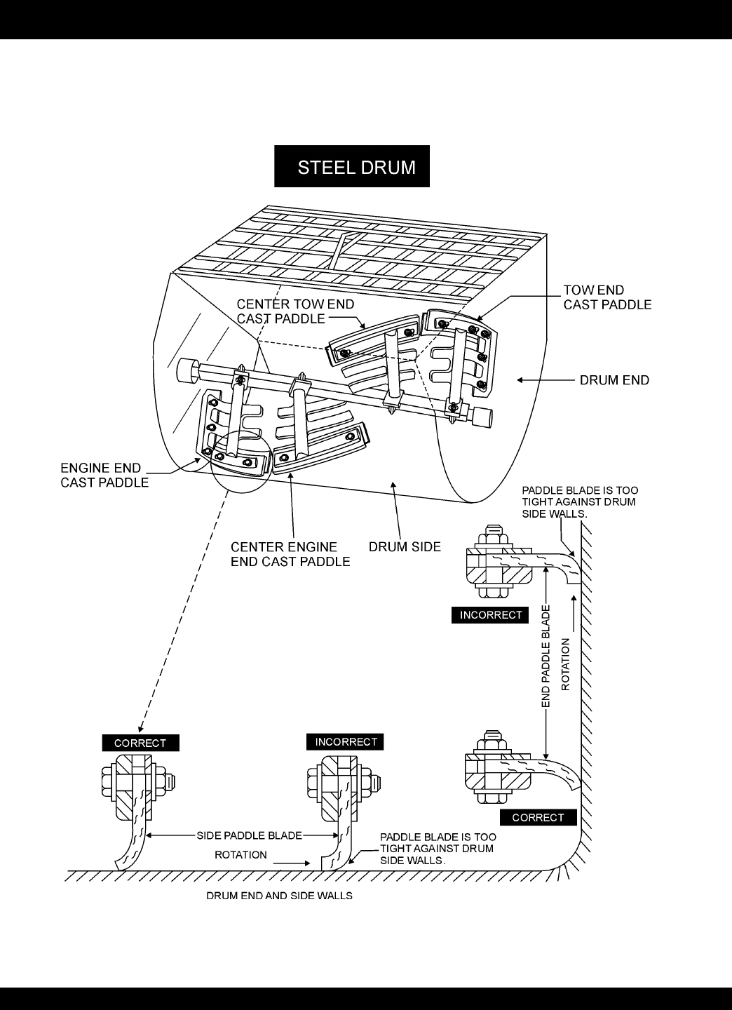
Figure 3. Paddle Blade Adjustment, Steel Drum
F
Figure 3 illustrates the paddle blade adjustment when using a steel drum. If material builds up on the drum, use a rubber mallet
to dislodge the material without adverse effect to the drum.

STOW MS-40M — PARTS & OPERATION MANUAL — REV. #1 (05/17/02) — PAGE 15
MS-40M MECHANICAL MIXER — NOTE PAGE
PAGE 16 — STOW MS-40M— PARTS & OPERATION MANUAL — REV. #1 (05/17/02)
MS-40M — INITIAL START-UP
This section is intended to assist the operator with the initial
start-up of the MS-40M mixer. It is extremely important that this
section be read carefully before attempting to use the mixer in
the field.
DO NOT use your mixer until this section is thoroughly
understood.
CAUTION:
Failure to understand the operation of the MS-
40M mixer could result in severe damage to
the mixer or personal injury.
See Figure 1 (Page 11) for the location of any control referenced
in this manual.
LUBRICANTS
ENGINE OIL
1. Remove the engine oil dipstick from its holder.
2. Determine if the engine oil is low, add correct amount of
engine oil to bring oil level to a normal safe level.
CLUTCH OIL
1. Check the oil level in the clutch compartment, fill with 30
SAE engine oil if needed.
REDUCTION GEAR OIL
1. Check the oil level in the reduction gear compartment, fill
with 90 SAE transmission oil if needed.
ZERK GREASE FITTINGS
1. Check the zerk grease fittings at each end of the mixing
drum. These grease fittings lubricate the dumping
mechanism. If the dumping handle is stiff or hard to move
lubricate these fittings.
FUEL
1. If your mixer has a gasoline engine, determine if the engine
fuel is low. If fuel is low, remove the fuel filler cap and fill
with
unleaded
gasoline.
CAUTION:
Handle fuel safely. Motor fuels are highly
flammable
and can be dangerous if
mishandled. DO NOT smoke while refueling.
Do not attempt to refuel mixer if the engine is
hot or running. Always allow engine to
cool
before refueling.
STARTING THE ENGINE (gasoline only)
The following steps outline the procedure for starting the engine.
Depending on the type of engine employed in the mixer the
steps may vary slightly. If your mixer has an electric motor
disregard this section.
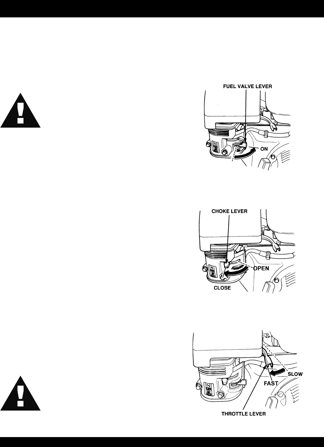
1. Move the fuel shut-off lever (Figure 4) to the ON position.
Figure 4. Fuel Shut-OFF Lever
2. To start a cold engine, move the choke lever (Figure 5) to
the CLOSED position.
Figure 5. Choke Lever
3. Move the throttle lever (Figure 6) away from the slow
position, about 1/3 of the way toward the fast position.
Figure 6. Throttle lever Lever
STOW MS-40M — PARTS & OPERATION MANUAL — REV. #1 (05/17/02) — PAGE 17
MS-40M — INITIAL START-UP
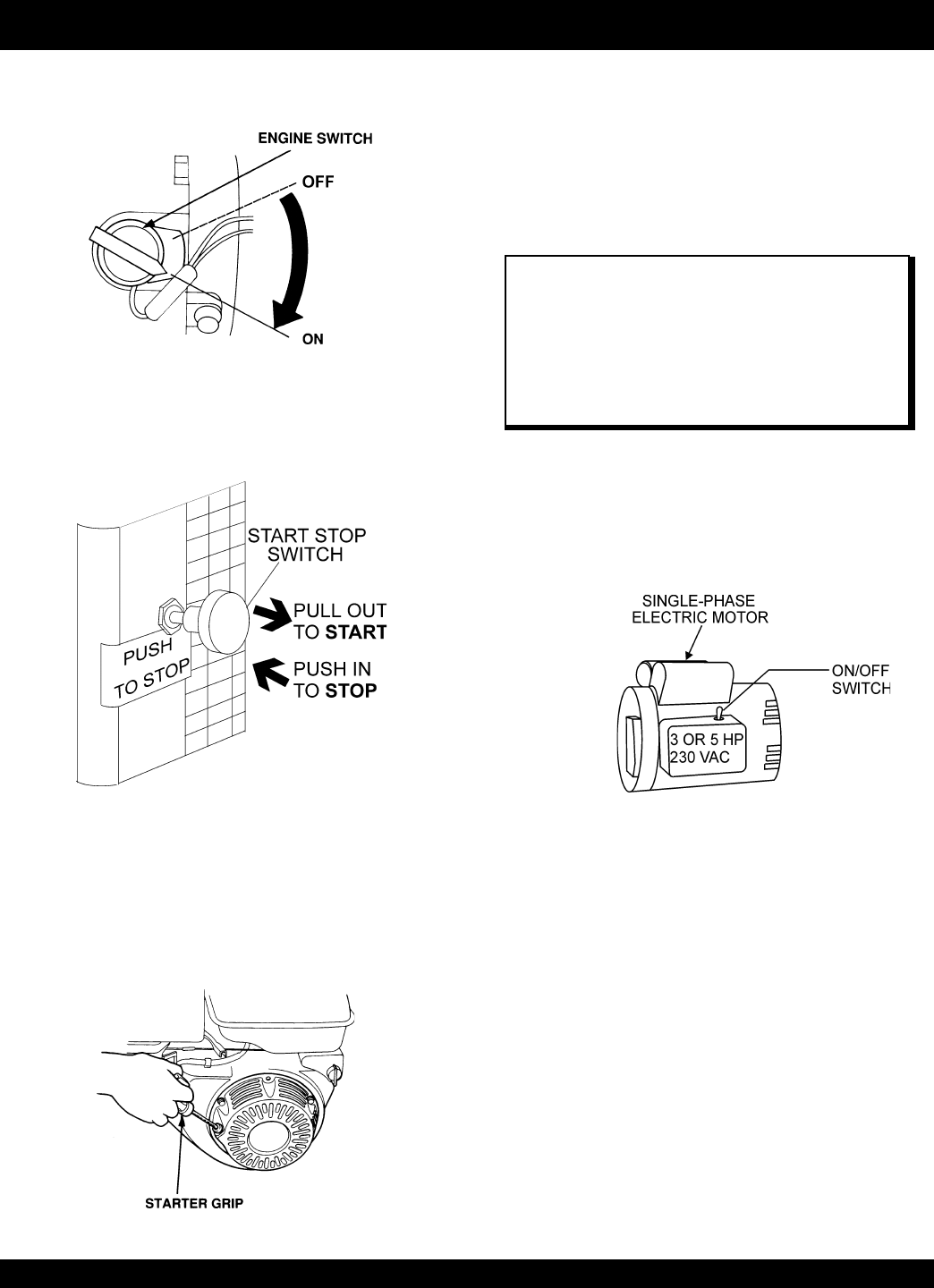
4. Turn the engine switch (Figure 7) to the ON position.
Figure 7. Engine ON/OFF Switch
5. Located on the engine cover is the main
start/stop
switch
(Figure 8). Pull this switch outward to start the engine.
Figure 8. Main ON/OFF Switch
Figure 9. Starter Grip
MIXING
1. The paddle shaft inside the drum should be rotating at this
time.
2. Lift the mixing bag compound onto the steel grate over the
bag cutter and let the contents fall into the drum.
3. Add water, and mix compound to desired consistency, then
dump.
NOTE
Be sure to stand clear of the
dump handle
when the
mixer is operational. Any binding of material between
the mixer blades and the drum will cause the drum
handle to move to the discharge position, thus causing
bodily harm.
STARTING THE ELECTRIC MOTOR
1. After the electric motor has been connected to a power
source by a licensed electrician it can then be ready for
use.
2. Set the electric motor's ON/OFF switch (Figure 10) to the
ON position.
Figure 10. Main ON/OFF Switch
3. Engage the clutch lever and verify that the paddle shaft is
rotating, then follow steps 1, 2 and 3 outlined in the mixing
section above.
STOPPING THE MIXER (gasoline)
1. Push the main
start/stop
switch (Figure 8) inward to stop
the engine.
turn the fuel shut-off valve to the OFF position
3. Disconnect the spark plug.
4. Clean drum of all debris and foreign matter.
STOPPING THE MIXER (electric)
1. Place the electric motor's
start/stop
switch (Figure 10) in
the OFF position.
2. Disconnect the electric motor's extension cord from its
power source.
3. Clean drum of all debris and foreign matter.
6. Pull the
starter grip
(Figure 9) lightly until you feel
resistance, then pull briskly. Return the starter grip gently.
Push the clutch lever forward, toward the tow tongue end
of the mixer. When engine starts adjust throttle lever so that
paddle shaft inside mixer rotates between 30 - 40 RPM's.
The number of RPM's will vary depending on engine type
and load.

PAGE 18 — STOW MS-40M— PARTS & OPERATION MANUAL — REV. #1 (05/17/02)
MS-40M — MAINTENANCE
WHEEL BEARINGS
After every 3 months of operation, remove the hub dust cap and
inspect the wheel bearings. Once a year, or when required,
disassemble the wheel hubs remove the old grease and repack
the bearings forcing grease between rollers, cone and cage
with a good grade of high speed wheel bearing grease (never
use grease heavier than 265 A.S.T.M. penetration (“No. 2.”) Fill
the wheel hub with grease to the inside diameter of the outer
races and also fill the hub grease cap.
Reassemble the hub and mount the wheel. Then tighten the
adjusting nut, at the same time turn the wheel in both directions,
until there is a slight bind to be sure all the bearing surfaces are
in contact.
Then back-off the adjusting nut 1/6 to 1/4 turn or to the nearest
locking hole or sufficiently to allow the wheel to rotate freely
within limits of .001" to .010" end play. Lock the nut at this position.
Install the cotter pin and dust cap, and tighten all hardware.
SHAFT SEALS
CAUTION:
IMPORTANT -DRUM HEAD SEAL CARE
Grease seals every 40 hours of operation using
any grade #1 lithium base grease. Apply
grease until visible inside of mixing tub (over
grease). this will purge seal system of
contamination.
CLUTCH REDUCTION ASSEMBLY LUBRICATION
The clutch reduction assembly has two separate compartments.
Each of which must be filled with its proper lubricant and checked
at regular intervals.
The
clutch compartment
should be filled with a good grade of
number 30 SAE engine oil which can be poured through the
filler hole located just above the clutch inspection door on the
opposite side of the transmission. Fill the clutch compartment
with 30 SAE engine oil until it overflows the oil level plug located
on the shifter side of the clutch compartment . Check this oil level
every two or three months and add oil as required. Drain and
refill once a year.
The
reduction gear, upper compartment
should be filled with
number 90 SAE oil, as used in automobile transmissions. The
filler plug is at the top of the reduction gear case and the oil level
plug is on the same side of the case as the clutch lever. Fill the
reduction gear compartment with 90 SAE transmission oil until it
overflows the oil level plug. Check this oil level every two or
three months and add oil as required. Drain and refill once a
year.
PADDLE SHAFT BEARINGS
The paddle shafts in the STOW MS-40M mixers rotate in sealed
ball bearings, which require no additional lubrication as they
are packed and sealed at the factory.
There is, on each end of the mixing drum, an zerk grease fitting.
Oil these fittings two or three times each week as they lubricate
the dumping mechanism of the mixing drum.
CAUTION:
■
Failure
to lubricate the zerk grease fittings
two or three times a week will cause the
dumping mechanism to stiffen, making the
mixer hard to dump.
BOLT CONNECTOR
A 5/8 " x 4 1/4" bolt is used as a connector pin located between
the reduction gear assembly and the paddle shaft. It is designed
to protect the transmission in the event a rock or other object
should get caught between the paddle blade and the drum, this
pin may shear. It is recommended that an extra bolt be kept on
hand so as to quickly make a replacement, if necessary.
BEARING BRACKET
Grease the bearing bracket every month.
CLEANING
Always disconnect the spark plug wire before cleaning the inside
of the drum.
Never pour or spray water over the gasoline engine or electric
motor.
For consistent performance, long life and high quality mixing,
thoroughly clean the mixer inside and out at the end of each
day’s operation. To prevent lumps of dried mortar from forming
and contamination of future batches, do not allow a buildup of
materials to form on the blades or anywhere inside the drum.
NOTE
This connector pin bolt is special. When replacing this
bolt consult the parts section of this manual for the
correct part number.
STOW MS-40M — PARTS & OPERATION MANUAL — REV. #1 (05/17/02) — PAGE 19
MS-40M — MAINTENANCE
Clutch Adjustment Mechanical 12 CF Mixer
If the rotating mixing paddles appear to be losing rotational speed,
it may be necessary to adjust the clutch. For optimum
performance Multiquip recommends 35-55 lbs. applied pressure
to the hand clutch lever. After the first initial operating hours (8)
check the clutch for proper ensasment pressure.
Clutch Adjustment Procedure
CAUTION:
Always stop the engine, disconnect the spark
plug or electrical power cord before attempting
this procedure.
1. To gain access to the " Gear Reduction Compartment"
remove the four 9/16-inch hex head bolts that secure the
hood to the engine and remove engine hood.
2. Drain the clutch compartment oil by removing the magnetic
3/8 plug located at the bottom of the Gear Reduction
Assembly.
3. To gain access to the "
clutch Inspection door
" remove
the six 1/2-inch capscrews and lockwashers that secure
the clutch inspection door. Remove door and gasket.
4. Check that the clutch is disengaged by pulling the shifter
lever towards the rear of the mixer.
5. Refer to Figure 11 for steps 5A through 5G:
NOTE
The Gear Reduction Compartment consist of two
compartments, a lower and upper.The
lower
compartment houses the clutch, the
uppe
r
compartment contains the actual gear reduction.
Remember each compartment requires a different type
of lubricating oil.
NOTE
If the clutch cannot be adjusted, it may be necessary to
inspect or replace the clutch.
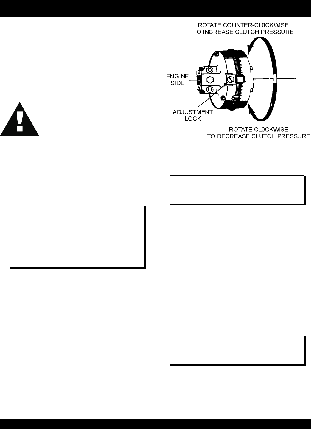
C. When the clutch has been satisfactorly adjusted reinstall
the
adjustment lock
P/N EM 934040 and tighten lock bolt.
D. Reinstall the
clutch Inspection door
using the six 1/2-
inch capscrews and lockwashers, and also check that the
gasket is not worn or broken.
E. When the clutch has been satisfactorly adjusted reinstall
the
adjustment lock
P/N EM 934040 and tighten lock bolt.
F. Remove the 3/8-inch square head pipe plug located on
the lower clutch compartment. Refill the clutch
compartment with 2 1/4 quarts of SAE 30 motor oil to the
level of the plug. When done reinstall plug.
G. Reinstall spark plug wire or electric power cord. Start
engine, check for proper clutch engagement and inspect
for any oil leaks.
Figure 11. Clutch Adjustment Lock Location
NOTE
Any questions regarding the above procedure please
contact the Multiquip Service Dept. at 1-800 421-1244.
A. Rotate the clutch using the recoil starter until the
adjustment
lock
(Figure 11) P/N EM934040 is visible.
Using a flat blade screwdriver loosen the adjustment bolt
just enough to release the adjustment lock.
B. Using a punch, rotate the
adjusting ring
P/N EM 934045
one notch at a time in the counter-clockwise direction until
a firm 35 to 55 lbs. pressure is felt when engaging the
clutch lever (the lever should snap into the engaged
position).

PAGE 20 — STOW MS-40M— PARTS & OPERATION MANUAL — REV. #1 (05/17/02)
MS-40M — TROUBLESHOOTING (ENGINE)
Practically all breakdowns can be prevented by proper
handling and maintenance inspections, but in the event of a
breakdown, please take a remedial action following the
diagnosis based on the Engine Troubleshooting (Table 3)
information shown below and on the proceeding page. If the
problem cannot be remedied, please leave the unit just as it
is and consult our company's business office or service
GNITOOHSELBUORTENIGNE.3ELBAT
MOTPMYS MELBORPELBISSOP NOITULOS
gnitratsrooP
leuffieesotroterubractcepsnI ?tignihcaersi enilleufkcehC
?leuFoN leuFddA
?knatleufniretaW .knatleufecalperrohsulF
?deggolcretlifleuF retlifleufecalpeR
?roterubrackcutS .msinahcemtaolfkcehC
?dersigulpkrapS .tinunoitingirotsinartkcehC.deluofsigulpkrapS
?etihw-eulbsigulpkrapS erastejroterubraC.gnikaelriadetcejni,noisserpmoctneiciffusnI .)wolfrevo(deggolc
krapsfopittatneserpkrapsoN ?gulp .nekorbrodekcarcdrocegatlovhgih,nekorbtinunoitingirotsinarT .deluoffigulpkrapsecalpeR.nekorbhctiwspotS/tratS
?liooN .deriuqersalioddA
sknilbpmalmralaerusserpliO ?gnitratsnopu ."rosneslio"tiucricnwodtuhscitamotuAkcehC
on"tuptuorewoptneiciffusnI "noisserpmoc
?revonruttonlliwenignE .tniojlexayrassecenfidnanotsipdnarednilycecalpeR
stlobgnitcennocdaehrednilyC ?esool .stlobgnitcennocdaehrednilycnethgiT
?degamadteksagdaehrednilyC .teksagdaehrednilycecalpeR
?taesevlavfonoitcnuflaM .sevlavtaes-eR
?esoolsigulpkrapS .gulpkrapsecalpeR
?sgnirnotsipnroW .sgnirnotsipecalpeR
tuptuorewoptneiciffusnI "noisserpmoc"
renaelc-rianinoitcnuflaM ?deggolcretlifria,metsys .retlifriaecalperronaelC
ecafretnimorfnignikaelriA rednilycdnaroterubracneewteb ?daeh
ecalpeR.daehrednilycdnaroterubracneewtebstlobnethgiT .teksagdaehrednilyc
?metsysleufninoitcnuflaM .retlifleufecalperronaelC .roterubracecalperronaelC .taolfroterubrackcehC

STOW MS-40M — PARTS & OPERATION MANUAL — REV. #1 (05/17/02) — PAGE 21
MS-40M — TROUBLESHOOTING (ENGINE/MIXER)
)DEUNITNOC(GNITOOHSELBUORTENIGNE.3ELBAT
MOTPMYS MELBORPELBISSOP NOITULOS
tuptuorewoptneiciffusnI staehrevodna"noisserpmoc"
?nafgniloocninoitcnuflaM .nafgniloocecalperrokcehC
?deggolcretlifekat-niriA .retlifekat-niriaecalperronaelC
leufhcumotsnruB
tsuahxefonoitalumuccarevO ?stcudorp .sevlavkcehcdnanaelC .yrassecenfiecalper,relffumkcehC
?gulpkrapsgnorW .gulpkrapsepytdetseggusserutcafunamhtiwgulpkrapsecalpeR
ylsuoinitnocsiroloctsuahxE "ETIHW"
gnorwsiliognitacirbuL ?ytisocsiv .ytisocsivtcerrochtiwliognitacirbulecalpeR
?sgnirnroW sgnirecalpeR
ylsuoinitnocsiroloctsuahxE "KCALB"
?deggolcrennaelcriA .renaelcriaecalperronaelC
tesneebtonsahevlavekohC ?noitisoptcerrocehtot .noitisoptcerrocehtotevlavekohctsujdA
nolaes,evitcefedroterubraC ?nekorbroterubrac .laesroroterubracecalpeR
tnemtsujdaroterubracrooP ?hcirootsnurenigne" .roterubractsujdA
GNITOOHSELBUORTREXIM.4ELBAT
MOTPMYS MELBORPELBISSOP NOITULOS
.etatortonlliwsedalB ?niprotcennocnekorB .gniredronehw751369N/PesU.niprotcennocecalpeR
?hctulcdetsujda-simroevitcefeD .hctulcecalperrotsujdA
murdmorfgnikaellairetaM .sdne tfahselddapevitcefedronroW ?slaes .slaesecalperrotsujdA
)tlit(egrahcsidottluciffidmurD
,metsysrenaelc-rianinoitcnuflaM ?deggolcretlifria .retlifriaecalperronaelC
troppusmurdnrowroevitcefeD ?stekcarb .ecalperrotekcarbotesaergylppA
.thgitootdetsujdasedalB .murdfosllawedishcuottsomlayehtlitnusedalbtsujdA

PAGE 22 — STOW MS-40M— PARTS & OPERATION MANUAL — REV. #1 (05/17/02)
How to read the marks and remarks used in this parts
book.
Items Found In the “Remarks” Column
Serial Numbers-Where indicated, this indicates a serial
number range (inclusive) where a particular part is used.
Model Number-Where indicated, this shows that the
corresponding part is utilized only with this specific model
number or model number variant.
Items Found In the “Items Number” Column
All parts with same symbol in the number column, *, #, +, %, or
■
, belong to the same assembly or kit.
MS-40M— — EXPLANATION OF CODE IN REMARKS COLUMN
NOTE
If more than one of the same reference number is
listed, the last one listed indicates newest (or latest)
part available.
NOTE
The contents of this catalog are
subject to change without notice
.

STOW MS-40M — PARTS & OPERATION MANUAL — REV. #1 (05/17/02) — PAGE 23
MS-40M— SUGGESTED SPARE PARTS
MS40M 1 TO 3 UNITS
Qty. P/N Description
2 ............ 491010 ............ RUBBER LATCH ASSY.
1 ............ EM200293 ....... PADDLE ARM TOW SIDE
1 ............ EM200294 ....... PADDLE ARM CENTER TOW SIDE
1 ............ EM200295 ....... PADDLE ARM CENTER ENGINE SIDE
1 ............ EM200296 ....... PADDLE ARM ENGINE SIDE
3 ............ EM200863 ....... RUBBER BLADE KIT (STEEL DRUM)
2 ............ EM200297 ....... U-BOLT
2 ............ EM200268 ....... U-BOLT
2 ............ 3530 ................PADDLE SHAFT, SEAL KIT
2 ............ EM902153 ....... BEARING, PADDLE SHAFT
3 ............ EM963157 ....... CONNECTOR BOLT
1 ............ EM934041 ....... CLUTCH, DRIVEN MEMBER
MS40M 5 TO 10 UNITS
Qty. P/N Description
4 ............ 491010 ............ RUBBER LATCH ASSY.
2 ............ EM200293 ....... PADDLE ARM TOW SIDE
2 ............ EM200294 ....... PADDLE ARM CENTER TOW SIDE
2 ............ EM200295 ....... PADDLE ARM CENTER ENGINE SIDE
2 ............ EM200296 ....... PADDLE ARM ENGINE SIDE
6 ............ EM200863 ....... RUBBER BLADE KIT (STEEL DRUM)
4 ............ EM200297 ....... U-BOLT
4 ............ EM200268 ....... U-BOLT
4 ............ 3530 ................PADDLE SHAFT, SEAL KIT
4 ............ EM902153 ....... BEARING, PADDLE SHAFT
5 ............ EM963157 ....... CONNECTOR BOLT
2 ............ EM934041 ....... CLUTCH, DRIVEN MEMBER
NOTE
Part numbers on this Suggested
Spare Parts List may supercede/
replace the P/N shown in the text
pages of this book.
PAGE 24 — STOW MS-40M— PARTS & OPERATION MANUAL — REV. #1 (05/17/02)
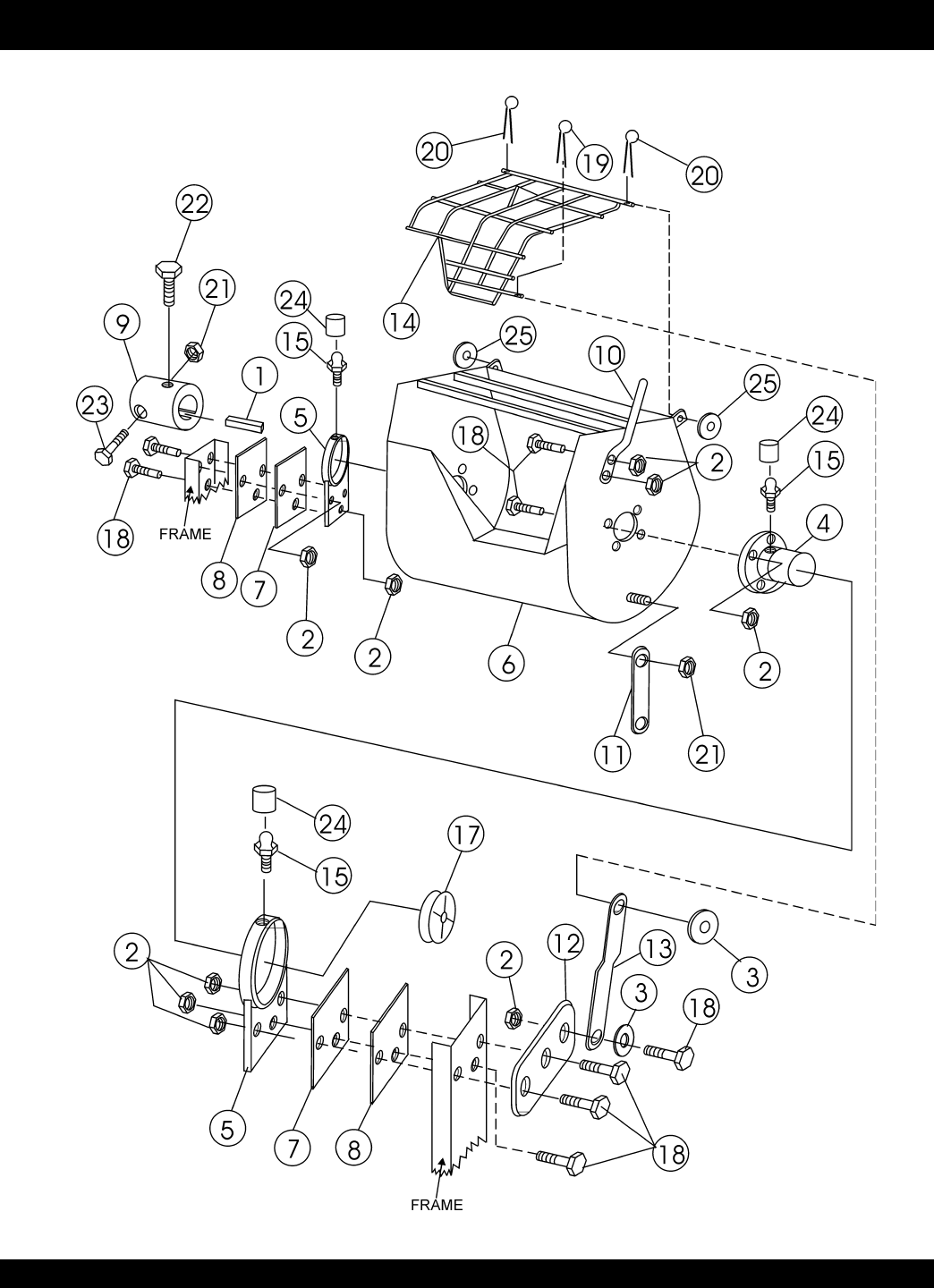
MS-40M — ENGINE SIDE PADDLE ASSY.
ENGINE SIDE PADDLE ASSY.

STOW MS-40M — PARTS & OPERATION MANUAL — REV. #1 (05/17/02) — PAGE 25
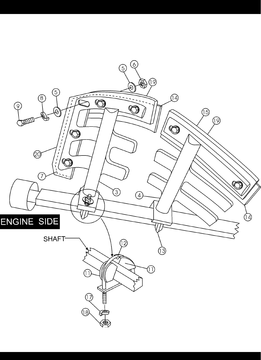
MS-40M — ENGINE SIDE PADDLE ASSY.
ENGINE SIDE PADDLE ASSY.
NO PART NO PART NAME QTY.REMARKS
3 EM200296 PADDLE ARM ENGINE SIDE 1
4 EM200295 PADDLE ARM CENTER ENGINE SIDE 1
5 0300B FLAT WASHER 5/16 28
6 0161D HEX NUT 5/16 14
7*#EM203433 END BACK-UP BLADE 2
8 0161C LOCK WASHER 5/16 14
9 1207 HHCS 5/16-18 1 3/4" 14
11 EM200292 PADDLE ARM INSERT CASTING 8
12 EM200297 END PADDLE U-BOLT 2
13 EM200268 CENTER PADDLE J-BOLT 2
14*#EM203432 CENTER BACK-UP BLADE 4
17 5054A LOCk WASHER 1/2" 8
18 968011 HEX NUT 1/2-13 8
19*EM200212 TOP RUBBER BLADE 4
20*EM200213 END RUBBER BLADE 2
EM200863 BLADE KIT(STEEL DRUM ONLY) ........................ 1 ...... INCLUDES ITEMS W/*AND MTG. HDW.
PAGE 26 — STOW MS-40M— PARTS & OPERATION MANUAL — REV. #1 (05/17/02)
MS-40M — TOW SIDE PADDLE ASSY.
TOW SIDE PADDLE ASSY.

STOW MS-40M — PARTS & OPERATION MANUAL — REV. #1 (05/17/02) — PAGE 27
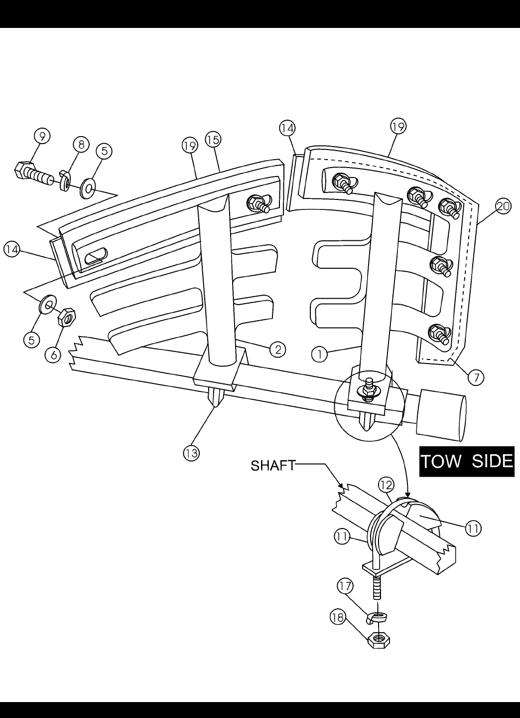
MS-40M — TOW SIDE PADDLE ASSY.
TOW SIDE PADDLE ASSY.
NO PART NO PART NAME QTY.REMARKS
1 EM200293 PADDLE ARM TOW SIDE 1
2 EM200294 PADDLE ARM CENTER TOW SIDE 1
5 0300B FLAT WASHER 5/16 28
6 0161D HEX NUT 5/16 14
7*#EM203433 END BACK-UP BLADE 2
8 0161C LOCK WASHER 5/16 14
9 1207 HHCS 5/16-18 1 3/4" 14
11 EM200292 PADDLE ARM INSERT CASTING 8
12 EM200297 END PADDLE U-BOLT 2
13 EM200268 CENTER PADDLE U-BOLT 2
14*#EM203432 CENTER BACK-UP BLADE 4
17 5054A LOCL WASHER 1/2" 8
18 968011 HEX NUT 1/2-13 8
19*EM200212 TOP RUBBER BLADE 4
20*EM200213 END RUBBER BLADE 2
EM200863 BLADE KIT(STEEL DRUN ONLY) ...................... 1 ........ INCLUDES ITEMS W/*AND MTG. HDW.
PAGE 28 — STOW MS-40M— PARTS & OPERATION MANUAL — REV. #1 (05/17/02)
MS-40M — PADDLE SHAFT ASSY.
TOW SIDE PADDLE ASSY.

STOW MS-40M — PARTS & OPERATION MANUAL — REV. #1 (05/17/02) — PAGE 29
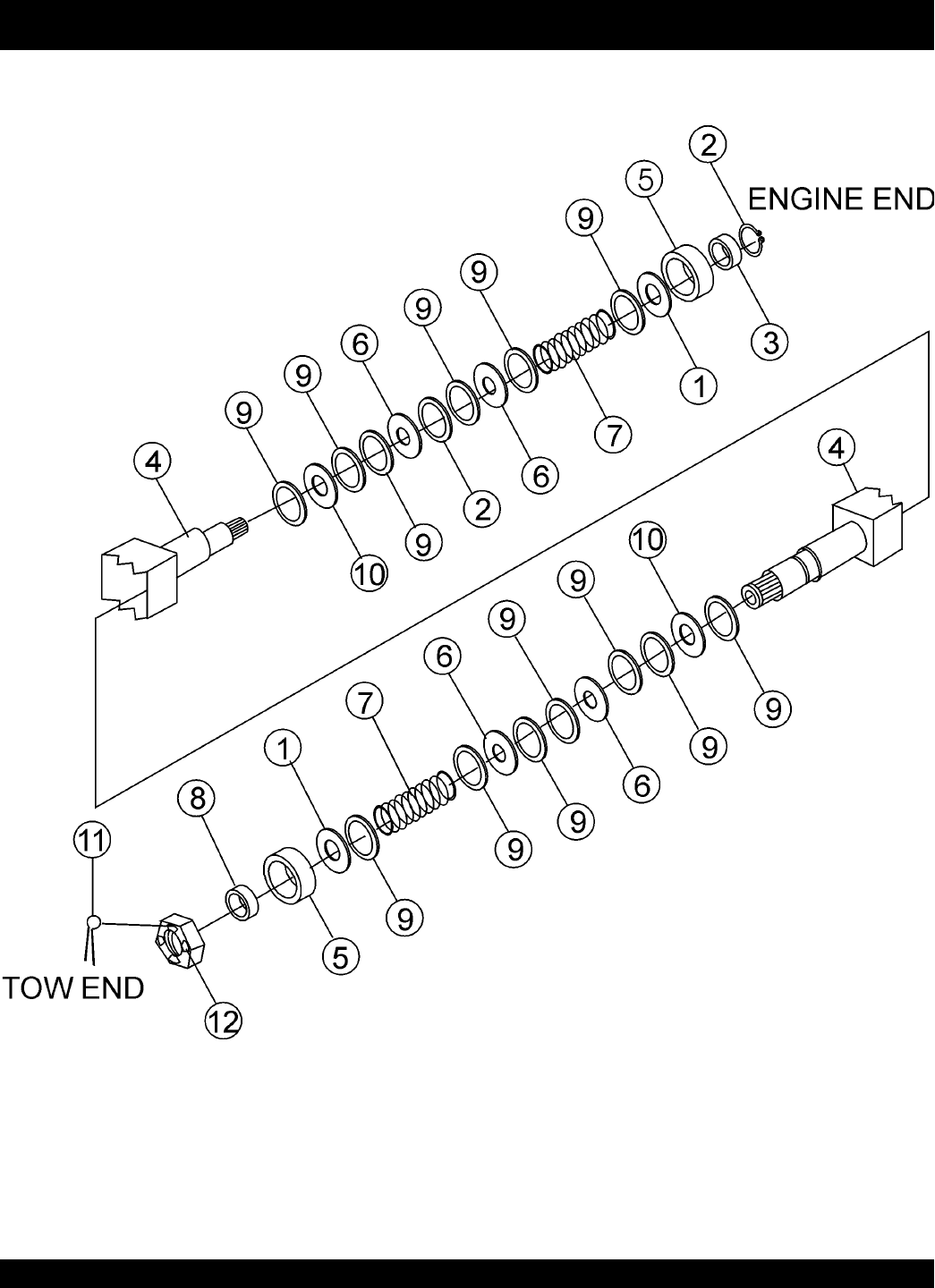
MS-40M — PADDLE SHAFT ASSY.
TOW SIDE PADDLE ASSY.
NO PART NO PART NAME QTY.REMARKS
1*13002 SEAL BEARING 1-1/2 ID 2
2 13348 RING, SNAP 1
3 13349 SPACER, SNAP RING 1
4 13344 SHAFT, PADDLE ..................................................... 1 .... STEEL DRUM ONLY
5 EM902153 BEARING, BALL 2
6*3019 SEAL PADDLE SHAFT, 1-1/8 ID 4
7 3024 SPRING PADDLE SHAFT 2
8 3047 SPACER, 2 X 1-1/8 X 1/4L 1
9 3061 SPACER 2-7/8 X 2-1/8 X .105 14
10*3494 SEAL, URETHANE 1-1/4 ID 2
3530 PADDLE SHAFT SEAL KIT .................................... 1 .... INCLUDES ITEMS W/*
PAGE 30 — STOW MS-40M— PARTS & OPERATION MANUAL — REV. #1 (05/17/02)
MS-40M — STEEL DRUM ASSY.
STEEL DRUM ASSY.

STOW MS-40M — PARTS & OPERATION MANUAL — REV. #1 (05/17/02) — PAGE 31
MS-40M — STEEL DRUM ASSY.
STEEL DRUM ASSY.
NO PART NO PART NAME QTY.REMARKS
1 EM010022 KEY, 3/8 SQ X 1 3/4 1
2 10176 NUT, NYLOC 1/2-13 17
3 13211 WASHER, FLAT, 1/2 USS 4
4 13277Y BOSS, BEARING 2
5 13345Y BEARING BRACKET 2
6 13346Y TUB, STEEL 1
7 EM200079 SHIM, BEARING BRKT. .135 2
8 EM200080 SHIM, BEARING BRKT. .187 2
9 EM200255 COUPLER, PADDLE SHAFT 1
10 EM201537Y DUMP LEVER 1
11 EM201731Y DRUM LATCH 1
12 EM203335Y HINGE, GRILL CLOSING BAR 1
13 EM203344Y BAR, GRILL OPENING 1
14 EM203449 GRILL, DRUM 1
15 2621 ZERK, GREASE STR 1/4-28 4
16 3214 SCREW, HHC 1/2-13 X 1 1/4 3
17 3249 CAP, DUST 1
18 5218 SCREW, HHC 1/2-13 X 1 1/2 12
19 7170 PIN, HITCH CLIP, 5/32 X 3-5/16 1
20 EM924015 PIN, COTTER, 3/16 X 1 2
21 9503 NUT, NYLOC 5/8-11 2
22 EM961019 SCREW, SQHS, 3/8-16 X 1-1/4, CUP 2
23 EM963157 SCREW, HHC 5/8-11 X 4-1/2, GR2 1
24 1162A CAP, GREASE ZERK 1
PAGE 32 — STOW MS-40M— PARTS & OPERATION MANUAL — REV. #1 (05/17/02)
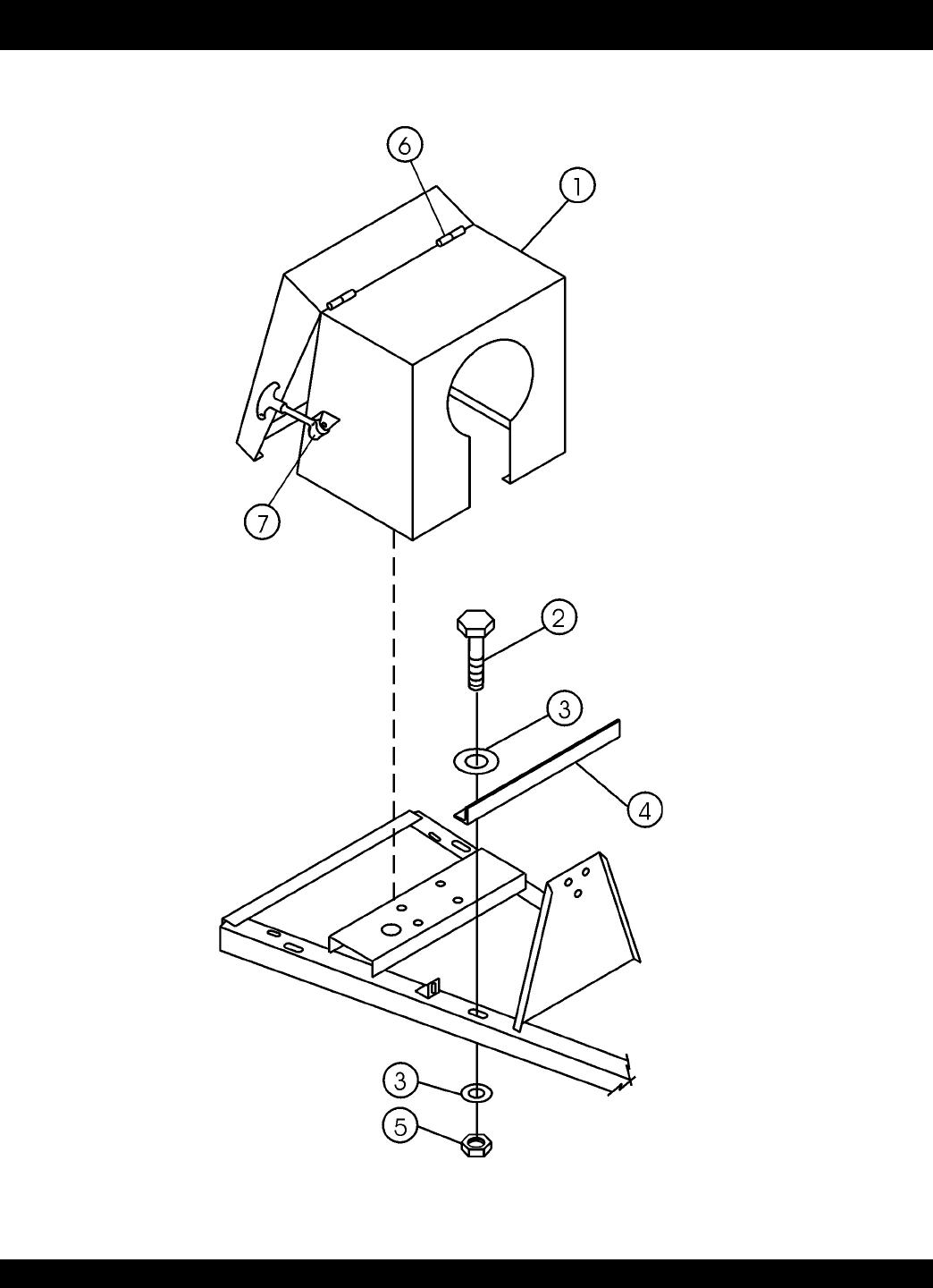
MS-40M — CAB ASSY.
CAB ASSY.

STOW MS-40M — PARTS & OPERATION MANUAL — REV. #1 (05/17/02) — PAGE 33
MS-40M — CAB ASSY.
CAB ASSY.
NO PART NO PART NAME QTY.REMARKS
1 EM202957Y CAB DOOR, COMPLETE ASSY. 1
2 1284 HHCS 3/8-16 X 1.1/2”4
3 4001 FLAT WASHER 3/8”8
4 202771 CAB FRONT SUPPORT ANGLE 1
5 10133 LOCK NUT 3/8-16 4
6 13333Y LATCH PIN ASSY. 2
7 491010 RUBBER LATCH ASSY. 2
PAGE 34 — STOW MS-40M— PARTS & OPERATION MANUAL — REV. #1 (05/17/02)
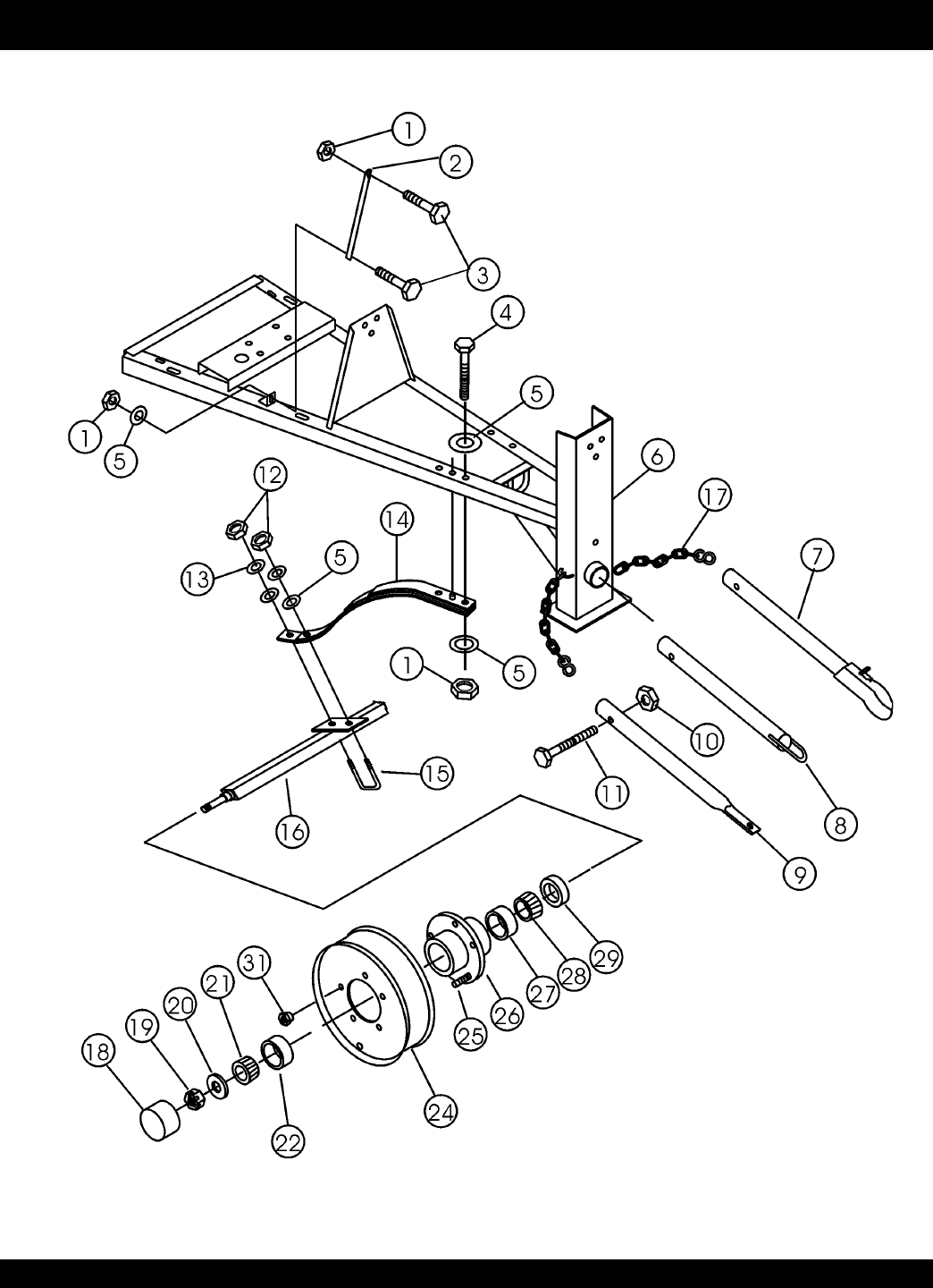
MS-40M — FRAME, WHEEL, TIRE AND HUB ASSY.
FRAME, WHEEL, TIRE AND HUB ASSY.

STOW MS-40M — PARTS & OPERATION MANUAL — REV. #1 (05/17/02) — PAGE 35
MS-40M — FRAME, WHEEL, TIRE AND HUB ASSY.
FRAME, WHEEL, TIRE AND HUB ASSY.
NO PART NO PART NAME QTY.REMARKS
1 10176 LOCK NUT 1/2-13 8
2 EM204086 TRANSMISSION SUPPORT BAR 2
3 5218 HHCS 1/2-13 X 1.1/2”4
4 2549 HHCS 1/2-13 X 3”4
5 0447 FLAT WASHER 1/2”14
6 EM202765Y FRAME W/A 1
7 EBC-1 BALL HITCH TOW BAR............................................ 1 ............ CONTACT UNIT SALES DEPT.
8 ELC-1 PINTLE EYE TOW BAR ............................................ 1 ............ CONTACT UNIT SALES DEPT.
9 EDC-1 PIN HOLE TOW BAR ................................................ 1 ............ CONTACT UNIT SALES DEPT.
10 5070B LOCK NUT 3/4-10 1
11 EM963580 HHCS 3/4-10 X 4.1/2”1
12 8244 HEX NUT 1/2-20 4
13 5054A LOCK WASHER 1/2”4
14 EM201225 AXLE SPRING 2
15 EM966204 SQUARE AXLE U-BOLT 1.1/2”2
16 EM202983 AXLE 1
17 13363 SAFETY CHAIN ASSY. 2
18#EM941278 GREASE CAP 2
19#EM968302 AXLE NUT 2
20#EM923161 AXLE WASHER 2
21#EM903113 OUTER BEARING CONE 2
22#EM903012 OUTER BEARING CUP 2
24#EM941257 WHEEL 13 X 4.1/2-5 ON 4.1/2” BC 2
25#EM941279 SERRATED WHEEL STUD 10
26#EM941277 HUB INC. 2
27#EM903169 INNER BEARING CUP 2
28#EM903168 INNER BEARING CONE 2
29#EM914324 SEAL 2
31 EM941280 WHEEL NUT 10
PAGE 36 — STOW MS-40M— PARTS & OPERATION MANUAL — REV. #1 (05/17/02)
MS-40M — NAME PLATE AND DECALS
NAME PLATE AND DECALS

STOW MS-40M — PARTS & OPERATION MANUAL — REV. #1 (05/17/02) — PAGE 37
MS-40M — NAME PLATE AND DECALS
NAME PLATE AND DECALS
NO PART NO PART NAME QTY.REMARKS
1 EM948423 DECAL : CAUTION 2
2 EM924801 DECAL : SAFETY INSTRUCTIONS 1
3 PLATE, SERIAL NO............................. 1 ........ CONTACT MQ SERVICE DEPT. W/MODEL & S/N
4 TBD DECAL : MQ STOW 1
5 DCL151 DECAL : INSPECT TOWING 2
6 13238 DECAL : DUMP CONTROL 1
7 511764 DECAL : DRIVE CONTROL 1
SEE DECAL ILLUSTRATIONS ON PAGE 6.
PAGE 38 — STOW MS-40M— PARTS & OPERATION MANUAL — REV. #1 (05/17/02)
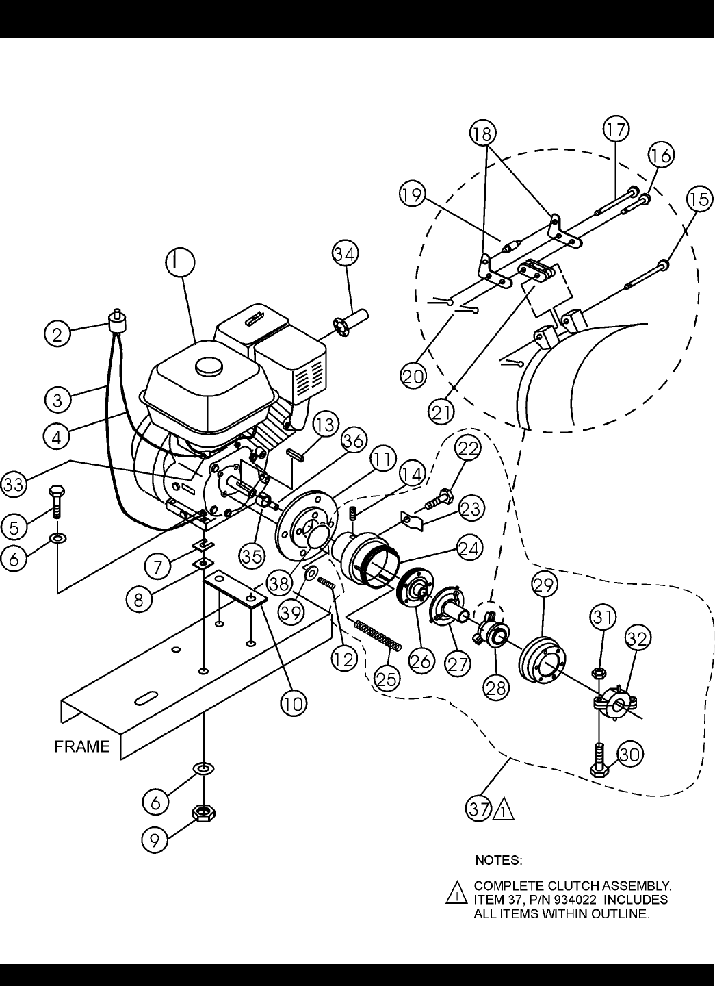
MS-40M — HONDA ENGINE ASSY.
HONDA ENGINE ASSY.

STOW MS-40M — PARTS & OPERATION MANUAL — REV. #1 (05/17/02) — PAGE 39
MS-40M — HONDA ENGINE ASSY.
HONDA ENGINE ASSY.
NO PART NO PART NAME QTY.REMARKS
1 EM203039 11HP HONDA ENGINE 1
2 EM940734 KILL SWITCH 1
3 EM203298 ENGINE KILL GROUND WIRE 1
4 EM203035 ENGINE KILL WIRE 1
5 9154 HHCS 3/8-16 X 1.3/4”4
6 10136 FLAT WASHER 3/8”8
7 EM100235 ENGINE SHIM .030 AR
EM100236 ENGINE SHIM .018 AR
EM100237 ENGINE SHIM .010 AR
8 EM203007 ENGINE PAD .187 AR
EM203016 ENGINE PAD .135 AR
EM203017 ENGINE PAD .060 AR
9 10133 LOCK NUT 3/8-16 4
10 EM204550 MOTOR MOUNT 2
11 EM203038 ADAPTER KIT ............................................................. 1 .......... INCLUDES ITEMS W/*
12*11090 STUD, 3/8 SHC 4
13 EM927066 SQ KEY 1
14 EM961045 SHSS 5/16-18 X 1/2”NYLOC 1
15#EM925013 LEVER PIN 3
16#EM925018 SHORT LINK PIN 3
17#EM925016 LONG LINK PIN 3
18#EM959012 LEVER 6
19#EM934054 ROLLER 3
20#5117 COTTER PIN 9
21#EM934053 CONNECTING LINK 6
22 9503 SLOTTED HHCS 1/4-20 X 1/2”1
23#EM934040 ADJUSTING LOCK 1
24#EM934039 CLUTCH HOUSING 1
25#EM918009 SPRING 3
26#EM934041 SPLINED CENTER W/FACING 1
27#EM934042 PRESSURE PLATE ASM 1
28#EM934043 RELEASE SLEEVE 1
29#EM934045 ADJUSTING RING 1
30#EM963289 BOLT 2
31#EM969009 LOCK NUT 2
32#EM934044 RELEASE BEARING ASM 1
33 1475 WIRE SPLICE 1
34 EM203149 EXHAUST DEFLECTOR 1
35*EM203040 SLEEVE 1
36 EM801570 PILOT BUSHING 1
37 EM934022 CLUTCH ASM ............................................................. 1 .......... INCLUDES ITEMS/W#
38*13377 OIL SEAL 4
39*13379 COPPER WASHER 4
PAGE 40 — STOW MS-40M— PARTS & OPERATION MANUAL — REV. #1 (05/17/02)
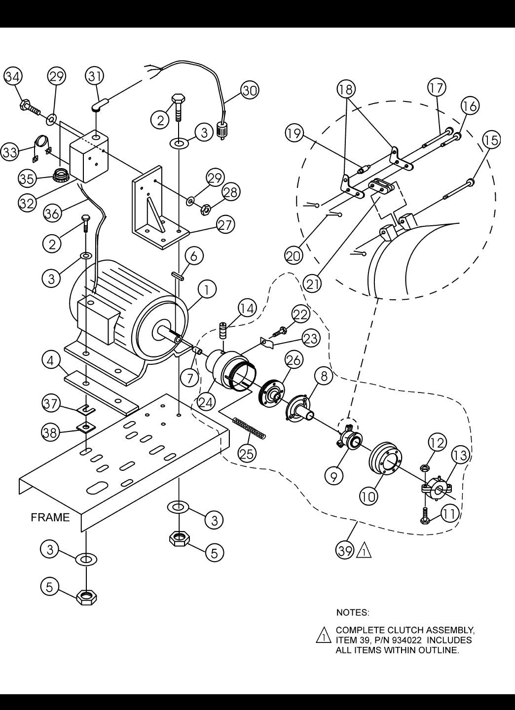
MS-40M — ELECTRIC MOTOR ASSY.
ELECTRIC MOTOR ASSY.

STOW MS-40M — PARTS & OPERATION MANUAL — REV. #1 (05/17/02) — PAGE 41
MS-40M — ELECTRIC MOTOR ASSY.
ELECTRIC MOTOR ASSY.
NO PART NO PART NAME QTY.REMARKS
1 EM939228 5 HP 1 PHASE ELECT MOTOR 1
1 EM239229 5 HP 3 PHASE ELECT MOTOR 1
2 1023 HHCS 3/8-16 X 1.1/4”8
3 10136 FLAT WASHER 3/8”16
4 EM204549 MOTOR MOUNT 2
5 10133 LOCK NUT 3/8-16 8
6 EM010009 SQ KEY 1
7 EM801570 BUSHING 1
8 EM934042 PRESSURE PLATE ASM 1
9#EM934043 RELEASE SLEEVE 1
10#EM934045 ADJUSTING RING 1
11#EM963289 BOLT 2
12#EM969009 LOCK NUT 2
13#EM934044 RELEASE BEARING ASM 1
14#EM961045 SHSS 5/16-18 X 1/2” NYLOC 1
15#EM925013 LEVER PIN 3
16#EM925018 SHORT LINK PIN 3
17#EM925016 LONG LINK PIN 3
18#EM959012 LEVER 6
19#EM934054 ROLLER 3
20#5117 COTTER PIN 9
21#EM934053 CONNECTING LINK 6
22 9503 SLOTTED HHCS 1/4-20 X 1/2”1
23#EM934040 ADJUSTING LOCK 1
24#EM934039 CLUTCH HOUSING 1
25#EM918009 SPRING 3
26#EM934041 SPLINED CENTER W/FACING 1
27 EM204526 MOUNT BRKT 1
28 10019 LOCK NUT 10-32 3
29 2203 FLAT WASHER #10 6
30 EM201794 PIG TAIL 1
31 0174 90 DEG ELBOW 1
32 EM940228 MOTOR STARTER 1 PHASE 1
32 3482 MOTOR STARTER 3 PHASE 1
33 EM940198 HEATER 1 PHASE 1
33 EM940209 HEATER 3 PHASE 1
34 8133 RHMS 10-32 X 3/4”3
35 EM940184 REDUCER BUSHING 1
36 EM012295 CONDUIT 1
37 EM100235 ENGINE SHIM .030 AR
EM100236 ENGINE SHIM .018 AR
EM100237 ENGINE SHIM .010 AR
38 EM203007 ENGINE PAD .187 AR
EM203016 ENGINE PAD .135 AR
EM203017 ENGINE PAD .060 AR
39 EM934022 CLUTCH ASM ............................................................. 1 .......... INCLUDES ITEMS/W#
PAGE 42 — STOW MS-40M— PARTS & OPERATION MANUAL — REV. #1 (05/17/02)
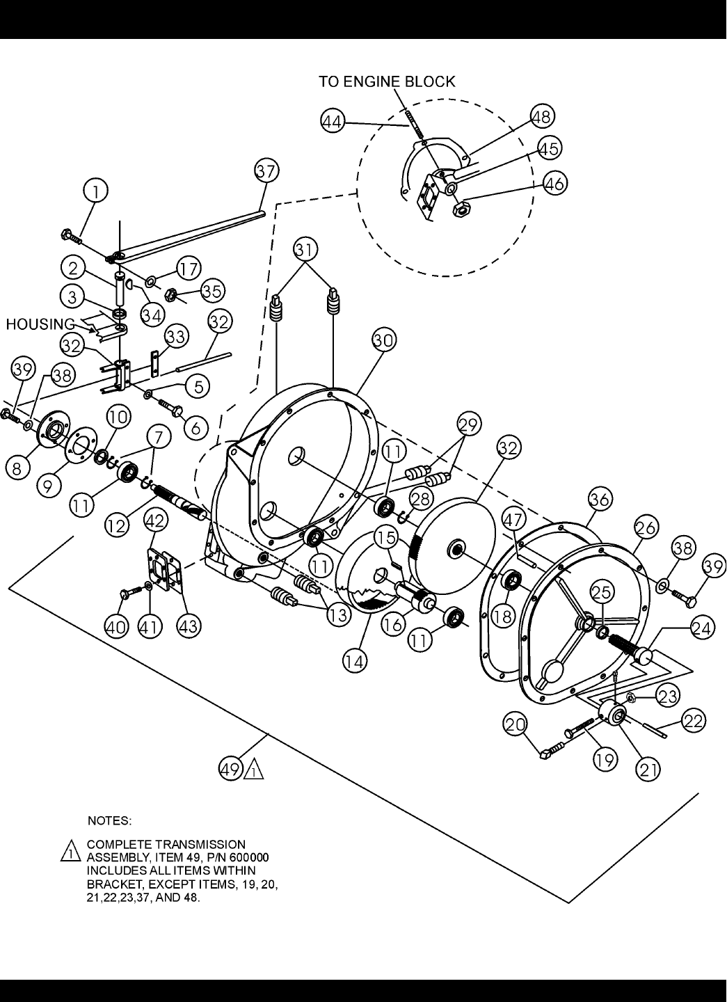
MS-40M — TRANSMISSION ASSY.
TRANSMISSION ASSY.

STOW MS-40M — PARTS & OPERATION MANUAL — REV. #1 (05/17/02) — PAGE 43
MS-40M — TRANSMISSION ASSY.
TRANSMISSION ASSY.
NO PART NO PART NAME QTY.REMARKS1
1#2200 HHCS 3/8-24 X 2" 1
2#EM600029 SHIFTER SHAFT 1
3#EM914005 SEAL 1
4#EM600028 CLUTCH YOKE 1
5#0181B LOCK WASHER 1/4”2
6#0730 HHCS 1/4-20 X 1”2
7#EM926029 SNAP RING 2
8#EM600023 BEARING RETAINER 1
9#EM600022 BEARING RETAINER GASKET 1
10#914209 SEAL 1
11#EM902091 BALL BEARING 4
12#EM600016 INPUT PINION SHAFT 1
13#EM911329 SQ HEAD MAG. PINE PLUG 3/8”2
14#EM600020 INTERNAL GEAR 1
15#EM010062 SQ KEY 3/8 X 1.3/8”1
16#EM600131 OUTPUT DRIVE PINION 1
17#10136 FLAT WASHER 3/8”1
18#EM902161 BALL BEARING 1
19 EM963157 HHCS 5/8-11 X 4.1/2” GD2 1
20 EM961019 SQHSS3/8-16 X 1.1/4” CUP 2
21 EM200255 PADDLE SHAFT COUPLER 1
22 EM010022 SQ KEY 3/8 X 3/8 X 1.3/4’1
23 9503 LOCK NUT 5/8-11 1
24#600015 OUTPUT SHAFT 1
25#914207 OIL SEAL 1
26#600014 TRANSMISSION COVER 1
27#EM600133 OUTPUT SHAFT GEAR 1
28#EM926036 SNAP RING 1
29#EM911064 SQ HEAD PINE PLUG 1/2 NPT 2
30#EM600012 MAIN TRANSMISSION HOUSING 1
31#EM911356 BREATHER VENT PIPE PLUG 1/2”2
32#EM600133 ROLL PIN 1
33#EM600024 LOCK PLATE 1
34#EM927048 WOODRUFF KEY #A 1
35#10133 LOCK NUT 3/8-16 1
36#EM600021 TRANSMISSION COVER GASKET 1
37 EM600018 SHIFTER LEVER 1
38#0161C LOCK WASHER 3/8”17
39#0202 HHCS 5/8-16 X 1”17
40#4196 HHCS 3/8-16 X 3/4”6
41#1875 INTER. SHKP WASHER 3/8”6
42#EM931233 SHIFTER COVER 1
43#EM600026 SHIFTER COVER GASKET 1
44#EM300999 STUD 7/16-14 X 2.1/16”4
45#2955 LOCK WASHER 7/16”4
46#EM968010 HEX NUT 7/16-14 4
47#EM925109 DOWEL PIN 3
48 EM801965 GASKET 1
49 EM600000 COMP.TRANS. ASM. ................................................ 1 ............. INCLUDES ITEMS W/#

PAGE 44 — STOW MS-40M— PARTS & OPERATION MANUAL — REV. #1 (05/17/02)
PAYMENT TERMS
Terms of payment for parts are net 10 days.
FREIGHT POLICY
All parts orders will be shipped collect or
prepaid with the charges added to the invoice.
All shipments are F.O.B. point of origin.
Multiquip’s responsibility ceases when a signed
manifest has been obtained from the carrier,
and any claim for shortage or damage must be
settled between the consignee and the carrier.
MINIMUM ORDER
The minimum charge for orders from Multiquip
is $15.00 net. Customers will be asked for
instructions regarding handling of orders not
meeting this requirement.
RETURNED GOODS POLICY
Return shipments will be accepted and credit
will be allowed, subject to the following
provisions:
1. A Returned Material Authorization must
be approved by Multiquip prior to shipment.
2. To obtain a Return Material Authorization,
a list must be provided to Multiquip Parts
Sales that defines item numbers,
quantities, and descriptions of the items to
be returned.
a. The parts numbers and descriptions
must match the current parts price
list.
b. The list must be typed or computer
generated.
c. The list must state the reason(s) for
the return.
d. The list must reference the sales
order(s) or invoice(s) under which
the items were originally purchased.
e. The list must include the name and
phone number of the person
requesting the RMA.
3. A copy of the Return Material
Authorization must accompany the return
shipment.
PRICING AND REBATES
Prices are subject to change without prior
notice. Price changes are effective on a specific
date and all orders received on or after that date
will be billed at the revised price. Rebates for
price declines and added charges for price
increases will not be made for stock on hand at
the time of any price change.
Multiquip reserves the right to quote and sell
direct to Government agencies, and to Original
Equipment Manufacturer accounts who use
our products as integral parts of their own
products.
SPECIAL EXPEDITING SERVICE
A $20.00 to $50.00 surcharge will be added to
the invoice for special handling including bus
shipments, insured parcel post or in cases
where Multiquip must personally deliver the
parts to the carrier.
LIMITATIONS OF SELLER’S LIABILITY
Multiquip shall not be liable here under for
damages in excess of the purchase price of the
item with respect to which damages are claimed,
and in no event shall Multiquip be liable for loss
of profit or good will or for any other special,
consequential or incidental damages.
LIMITATION OF WARRANTIES
No warranties, express or implied, are made in
connection with the sale of parts or trade
accessories nor as to any engine not
manufactured by Multiquip. Such warranties
made in connection with the sale of new,
complete units are made exclusively by a
statement of warranty packaged with such
units, and Multiquip neither assumes not
authorizes any person to assume for it any
other obligation or liability whatever in
connection with the sale of its products. A part
from such written statement of warranty, there
are no warranties, express, implied or statutory,
which extend beyond the description of the
products on the face hereof.
4. Freight is at the sender’s expense. All
parts must be returned freight prepaid to
Multiquip’s designated receiving point.
5. Parts must be in new and resalable
condition, in the original Multiquip package
(if any), and with Muiltiquip part numbers
clearly marked.
6. The following items are not returnable:
a. Obsolete parts. (If an item is listed
in the parts price book as being
replaced by another item, it is
obsolete.)
b. Any parts with a limited shelf life
(such as gaskets, seals, “O” rings,
and other rubber parts) that were
purchased more than six months
prior to the return date.
c. Any line item with an extended dealer
net price of less than $5.00.
d. Special order items.
e. Electrical components.
f. Paint, chemicals, and lubricants.
g. Decals and paper products.
h. Items purchased in kits.
7. The sender will be notified of any material
received that is not acceptable.
8. Such material will be held for 5 working
days from notification, pending
instructions. If a reply is not received
within 5 days, the material will be returned
to the sender at his expense.
9. Credit on returned parts will be issued at
dealer net price at time of the original
purchase, less a 15% restocking charge.
10. In cases where an item is accepted for
which the original purchase document
can not be determined, the price will be
based on the list price that was effective
twelve months prior to the RMA date.
11. Credit issued will be applied to future
purchases only.
Effective: July 1, 2000 TERMS AND CONDITIONS OF SALE — PARTS

STOW MS-40M — PARTS & OPERATION MANUAL — REV. #1 (05/17/02) — PAGE 45
NOTE PAGE

^^^^^*^^^^^^^^^^^^^^^^^^^^^^^^^*^6668
PARTS AND OPERATION MANUAL
HERE'S HOW TO GET HELP
PLEASE HAVE THE MODEL AND SERIAL NUMBER
ON-HAND WHEN CALLING
PARTS DEPARTMENT
800-427-1244 or 310-537-3700
FAX: 800-672-7877 or 310-637-3284
SERVICE DEPARTMENT/TECHNICAL ASSISTANCE
800-478-1244 or 310-537-3700
FAX: 310- 537-4259
WARRANTY DEPARTMENT
888-661-4279, or 310-661-4279
FAX: 310- 537-1173
MAIN
800-421-1244 or 310-537-3700
FAX: 310-537-3927
MULTIQUIP INC.
POST OFFICE BOX 6254
CARSON, CA 90749
310-537-3700 • 800-421-1244
FAX: 310-537-3927
E-MAIL: mq@multiquip.com
WWW: multiquip.com
Atlanta • Boise • Dallas • Houston • Newark
Quebec, Canada • Manchester, UK • Rio De Janiero, BR • Guadalajara, MX
