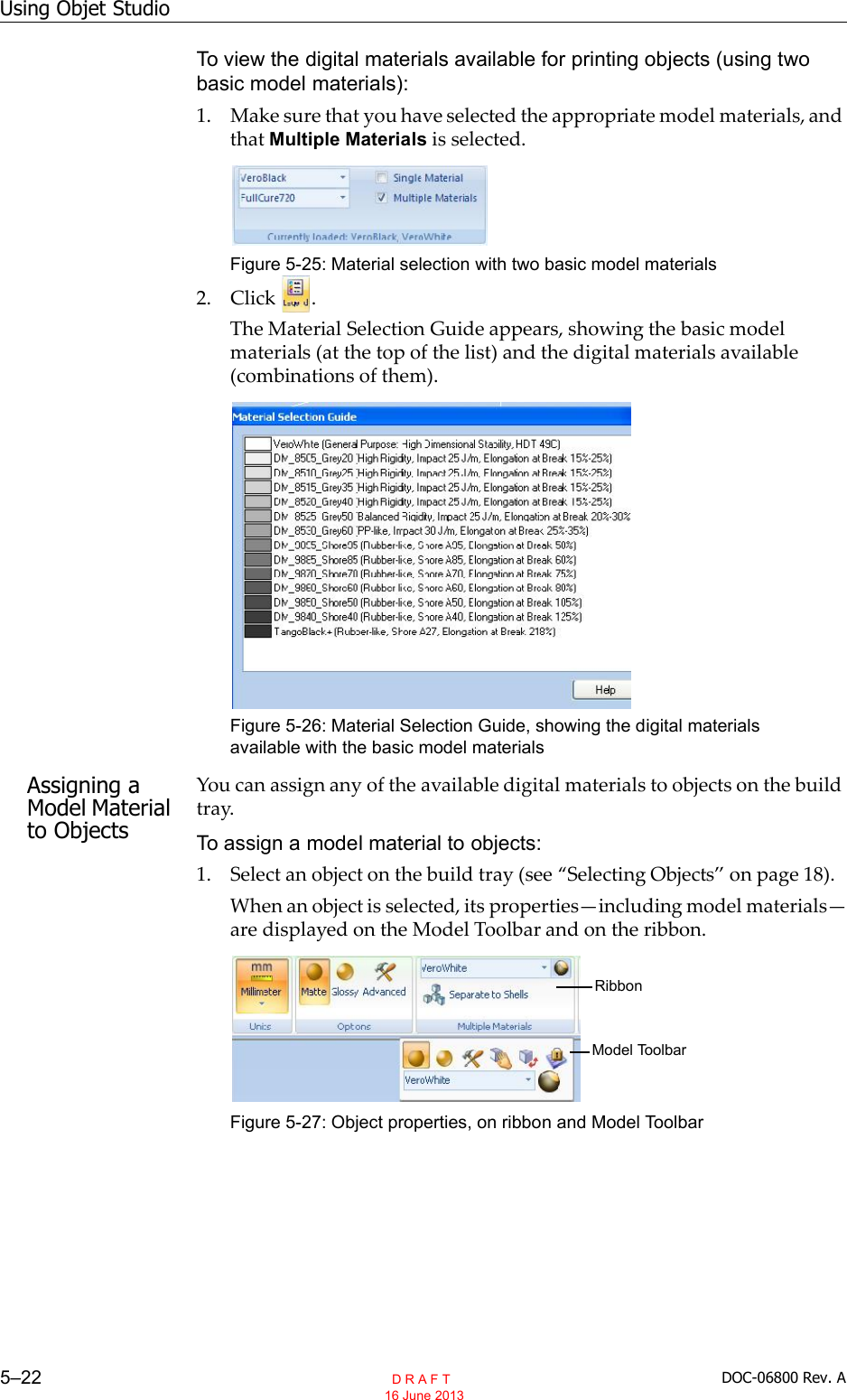
Stratasys XLRFID Assembly of RFID reader and antenna boards User Manual user manaul
Stratasys Ltd Assembly of RFID reader and antenna boards user manaul
UserManual.wiki
>
Stratasys
>
XLRFID User Manual
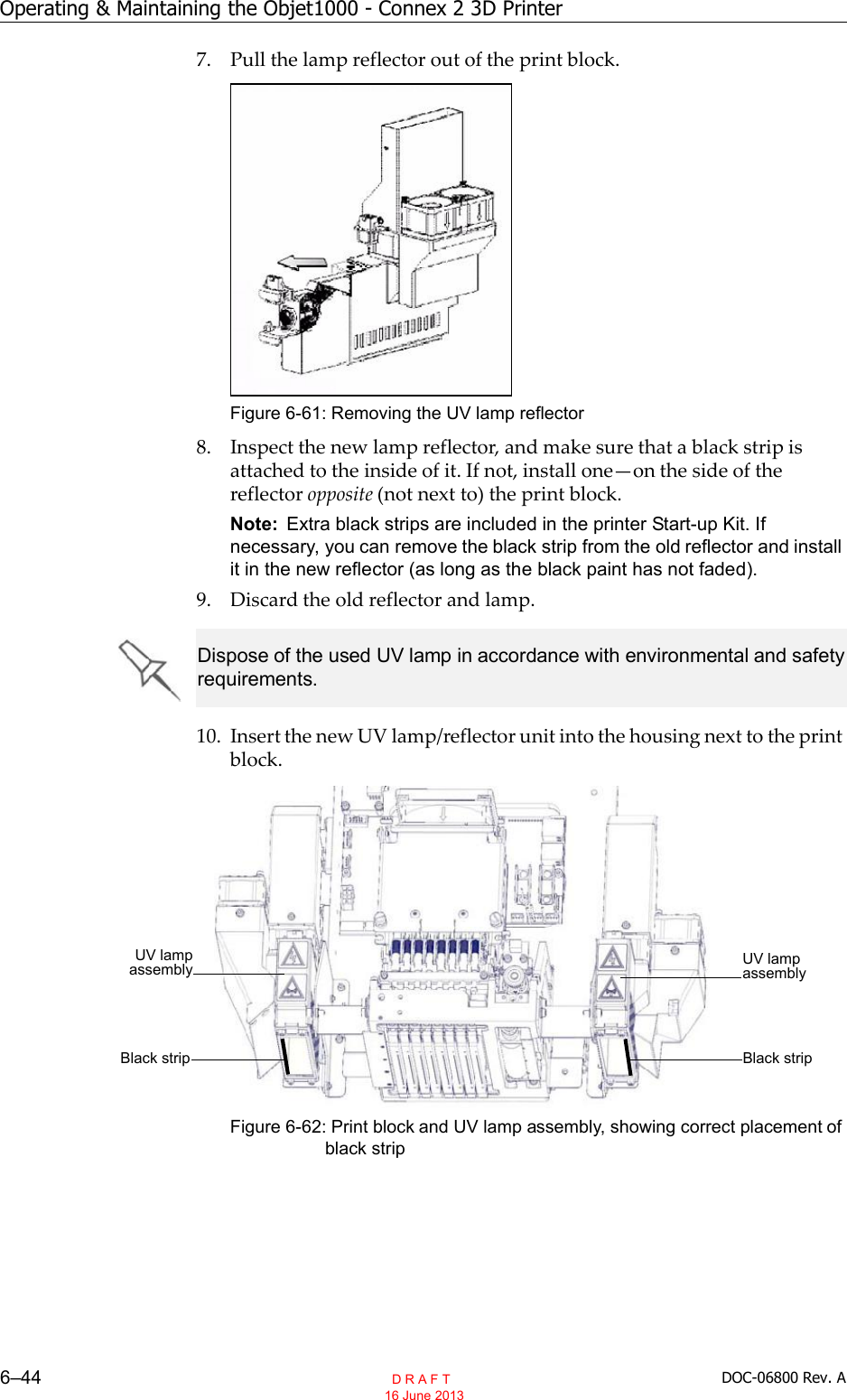
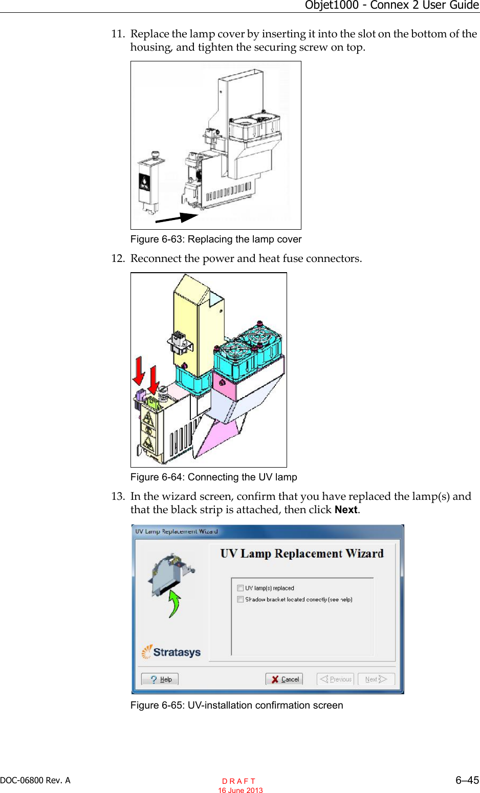
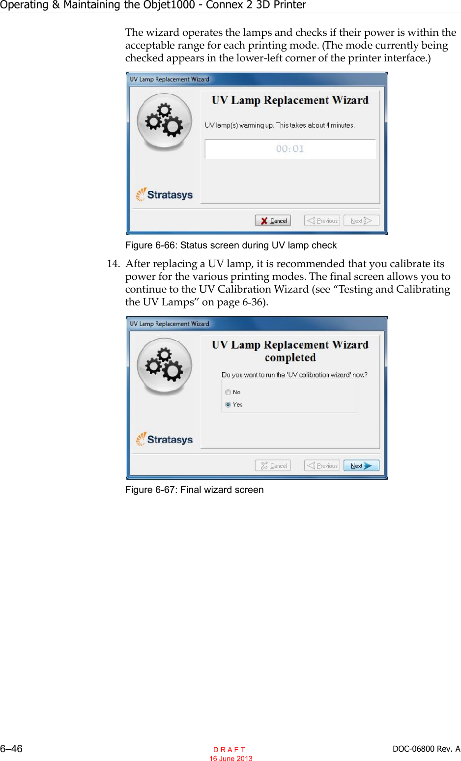
>
user manaul
Contents
1.
test setup photos
2.
user manaul
user manaul
Navigation menu
Upload a User Manual
Namespaces
Wiki Guide
HTML
PDF
Info
Views
User Manual
Discussion / Help
Navigation

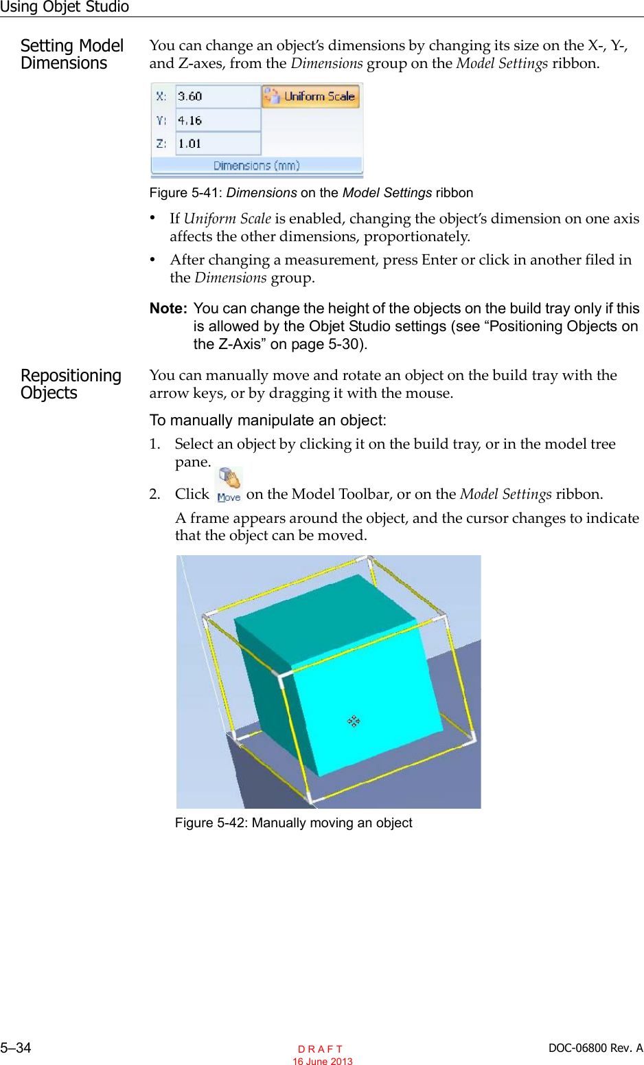

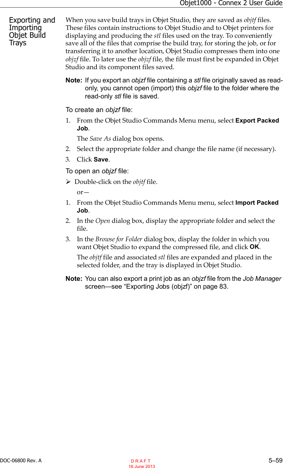

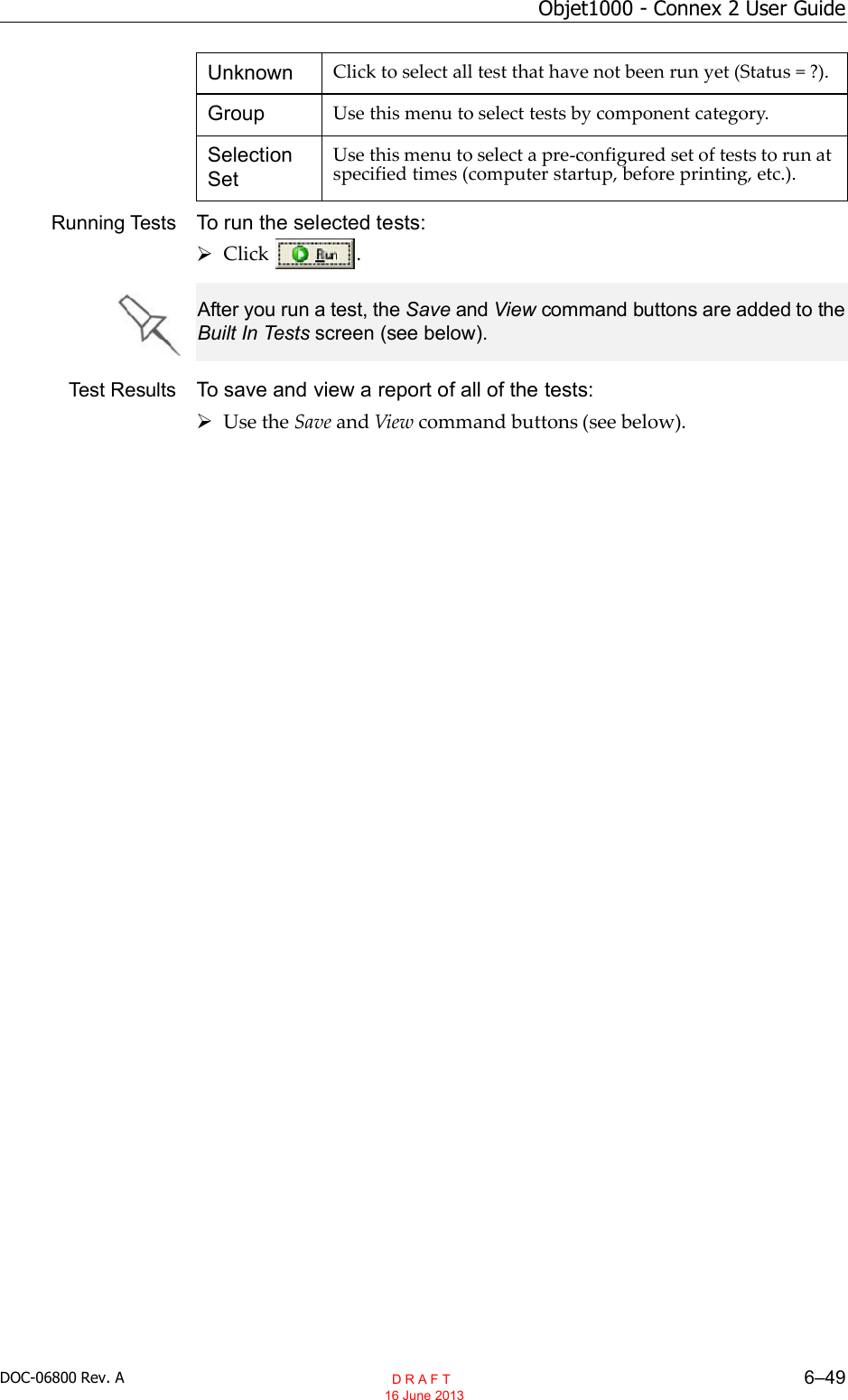
![Operating & Maintaining the Objet1000 - Connex 2 3D Printer6–50 DOC-06800 Rev. ACommand Buttons You click the command buttons, on the right side of the screen, to performthe following operations:RunClick to run the selected tests.ResetClick to clear previously run tests. This returns the status of each test toUnknown (?).SaveClick to save a report that summarizes the tests run. The report is saved asan HTML file. You can save any number of reports for the tests you run; thename of the file saved is BITReport [date][time].htm. By default, these filesare saved in the Objet installation folder, but you can save it in any otherfolder.ViewClick to display the latest test report that you saved. (You can view othertest reports by opening the relevant files in your Web browser. To do so,open Windows Explorer, and double click the BITReport file.)CloseClick to close the Built in Tests screen.Summary On the right side of the screen, a symbol represents the combined results ofall the tests run, using the symbols from the Status column.All tests successfully completed.At least one test failed.Not all tests performed. D R A F T 16 June 2013](https://usermanual.wiki/Stratasys/XLRFID.user-manaul/User-Guide-2087182-Page-170.png)