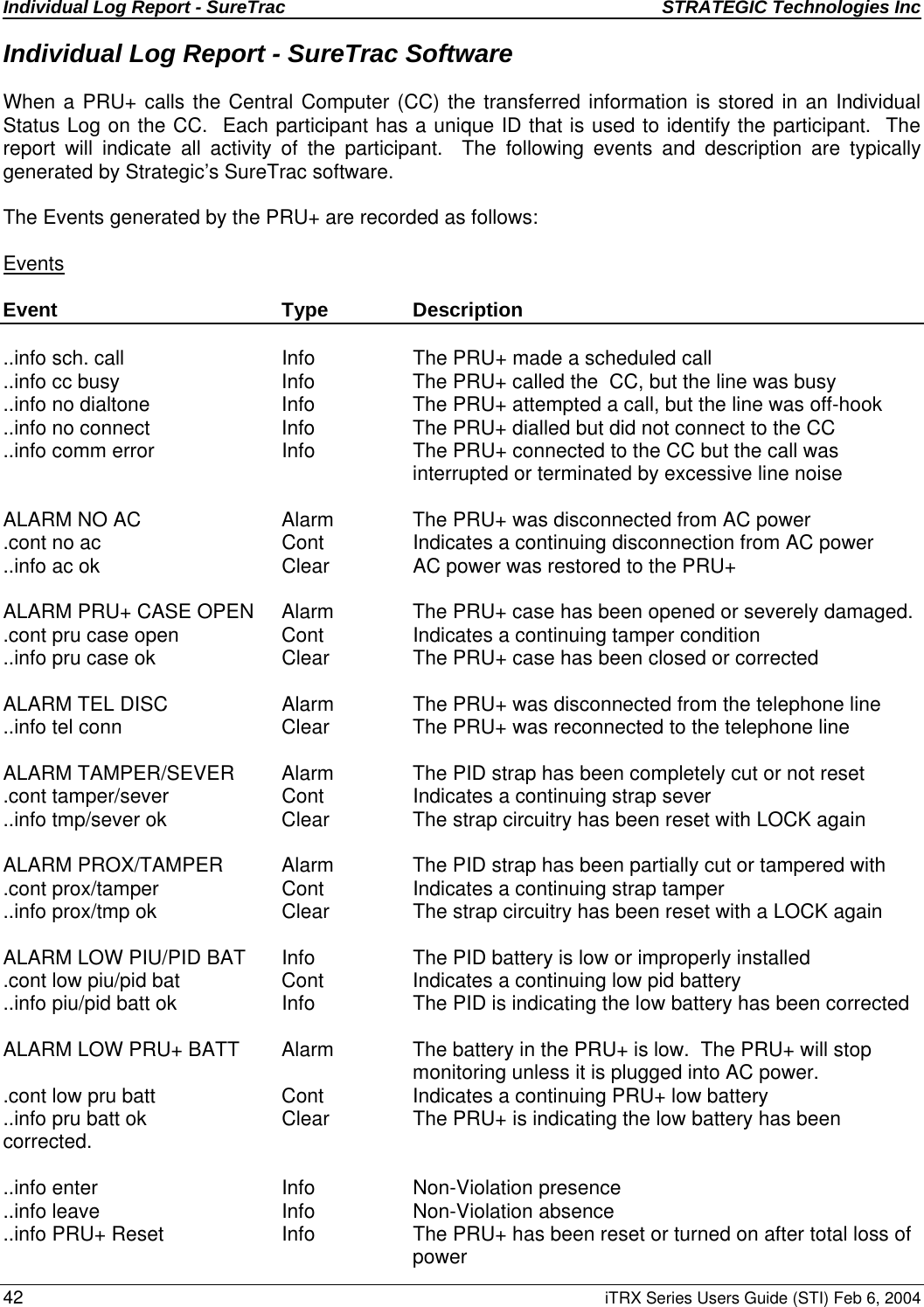
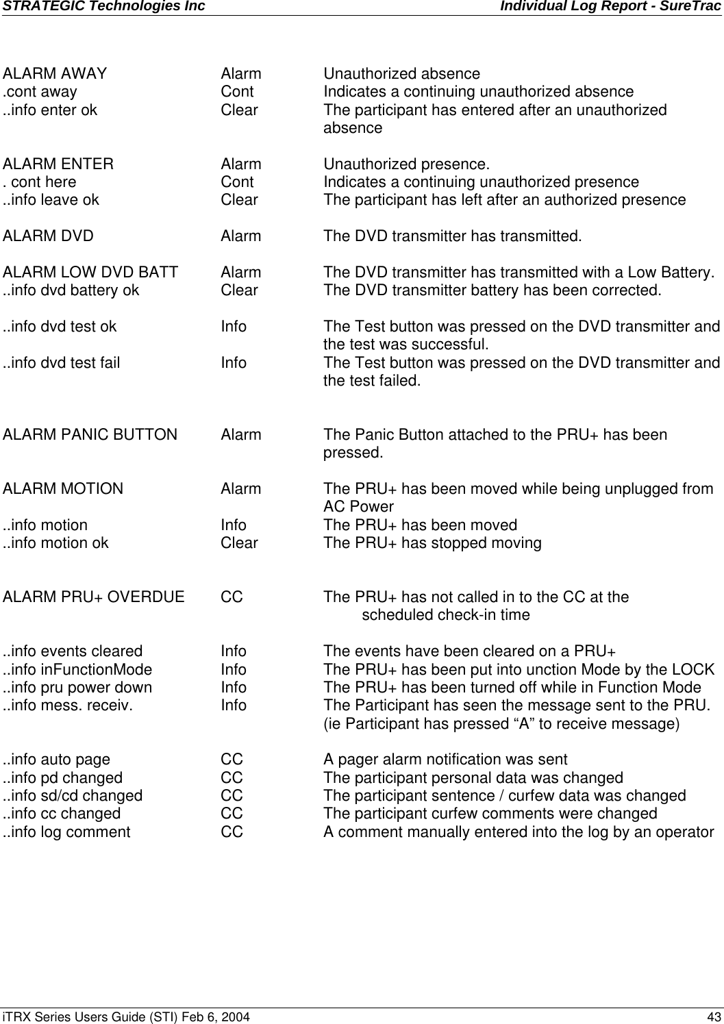
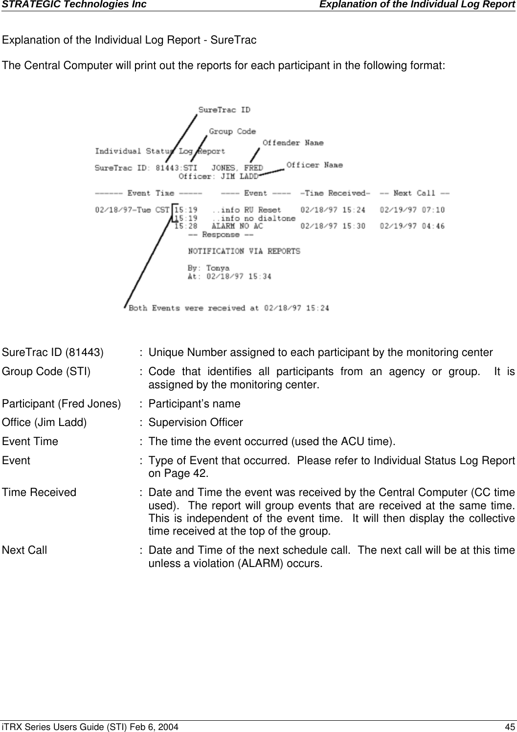
Strategic Technologies DUALTRAKPID Dual Trak Personal Identified Device User Manual iTRX Users Guide FCC

Strategic Technologies Inc. Dual Trak Personal Identified Device iTRX Users Guide FCC

users manuel

STRATEGIC Technologies Inc.    ACU Overview iTRX Series Users Guide (STI) Feb 6, 2004    PAGE 1 NOTICE :             This Users Guide is for use with version 3.2 of the iTRX series ACU Firmware   See Page 7, ACU Operations (Active Mode) for information regarding how to determine the ACU Firmware version.  Different versions of the ACU software may not have the same features described in this manual and / or may function differently than this manual states.   United States FCC, Part 15   These devices comply with Part 15 of the FCC rules.  Operation is subject to conditions: (1) This device may not cause harmful interference, and (2) this device must accept interference received, including interference that may cause undesired operation.   ITX FCC Identifier:     OEHDUALTRAKPID  LOCK FCC Identifier: OEHSTILOCK   NOTE: THE MANUFACTURER IS NOT RESPONSIBLE FOR ANY RADIO OR TV INTERFERENCE CAUSED BY UNAUTHORIZED MODIFICATIONS TO THIS EQUIPMENT. SUCH MODIFICATIONS COULD VOID THE USER’S AUTHORITY TO OPERATE THE EQUIPMENT.   Industry Canada   These devices comply with requirements of the radio standards specifications and procedures issued by Industry Canada.       LOCK: Certificate No. 9937, certification no. 32851021360.      This manual is for users of Strategic’s equipment only.  All matters concerning this manual should be directed to Strategic Technologies Inc.   Printed in Canada.  All rights reserved.       Strategic Technical Support  For help related to the equipment in this Users’ Guide, call (604) 576-8658, ext. 230.
 STRATEGIC Technologies Inc  2 iTRX Series Users Guide (STI) Feb 6, 2004
STRATEGIC Technologies Inc  ACU Overview   iTRX Series Users Guide (STI) Feb 6, 2004  3  Table Of Contents     ACU Overview ..........................................................................................................................................5   Required field equipment for installing and/or removing a unit .....................................................5  ACU Basics...............................................................................................................................................6   Turning the ACU on ......................................................................................................................6   Turning the ACU off ......................................................................................................................6   ACU Indicator Lights and Buttons.................................................................................................7   ACU Operation (Active Mode).......................................................................................................7   ACU Calling the Central Computer ...............................................................................................8     Call Attempt Error Messages ............................................................................................8   Blind Dial Mode .................................................................................................................9  iTX Basics...............................................................................................................................................10 Features......................................................................................................................................10 Resetting the iTX.........................................................................................................................10  LOCK Basics ..........................................................................................................................................11   Replacing the Battery..................................................................................................................11  CMU Basics ............................................................................................................................................12 Installation...................................................................................................................................12 Removal......................................................................................................................................12  ACU Installation Procedures...................................................................................................................13  Active Mode Installation .........................................................................................................................14 Pre-Installation ............................................................................................................................14 ACU Installation - Quick Install....................................................................................................14   iTX Installation.................................................................................................................15       Figure 5: Attaching the strap to the baseplate.....................................................15       Figure 6: Sliding the iTX onto the baseplate........................................................16   ACU Installation - using Test Mode.............................................................................................17   Installation Completion....................................................................................................17   De-Installation / Removal............................................................................................................18   Figure 7: How to cut the iTX for removal.............................................................19  Passive Mode .........................................................................................................................................20   Important Information Regarding Passive Mode Operation........................................................20  Passive Mode Installation .......................................................................................................................21  Pre-Installation ............................................................................................................................21  ACU Installation .........................................................................................................................21   Installation Completion....................................................................................................21   Downloading Information inside the ACU ...................................................................................22   De-Installation / Removal............................................................................................................22
 STRATEGIC Technologies Inc  4 iTRX Series Users Guide (STI) Feb 6, 2004  Function Mode ........................................................................................................................................24  Extended Function Mode........................................................................................................................26  Test Mode...............................................................................................................................................31  Quick Install ............................................................................................................................................33  Motion Sensor.........................................................................................................................................34  ACU/ITX Preventive Maintenance ..........................................................................................................35  Returned ACUs...........................................................................................................................35   Physical Checks..............................................................................................................35   Electrical Checks.............................................................................................................36  Returned ITXs.............................................................................................................................37   Physical Checks..............................................................................................................37   Electrical Checks.............................................................................................................37   Testing an ITX.................................................................................................................37  Individual Log Report – Renaissance software.......................................................................................38  Event Text Glossary....................................................................................................................38   Reading the Individual Log Report  ............................................................................................40  Event Text ..................................................................................................................................41  Individual Log Report - SureTrac Software.............................................................................................42  Events .........................................................................................................................................42  Event Type Definitions ................................................................................................................44   Explanation of the Individual Log Report ....................................................................................45  Frequently Asked Questions...................................................................................................................48  Trouble-Shooting ....................................................................................................................................50  ACU Tips.....................................................................................................................................50  iTX Tips.......................................................................................................................................52  LOCK Tips...................................................................................................................................53  System Definitions ..................................................................................................................................54
STRATEGIC Technologies Inc  ACU Overview   iTRX Series Users Guide (STI) Feb 6, 2004  5 ACU Overview     Strategic’s iTRX Series ACU combines ease of use with unequalled flexibility.  The features of the ACU have been designed to simplify equipment installation and program management, and to provide for future expansion and enhancements. The features of the ACU include:  ¾  Small footprint - 0.4 square feet   ¾  Lightweight (w/dual battery - 3.7 lbs, w/single battery - 2.5 lbs)   ¾  Compact, aesthetic design  ¾  Removable AC power adapter, with latching connector  ¾  Two RJ-11 modular telephone jacks for a line connection and a telephone  ¾  15-pin expansion connector  ¾  16-character by 2-line visual display panel for displaying configuration settings, installation instructions, and other information  ¾  Two front panel input buttons for user input and changing configuration settings  ¾ Internal Antenna  ¾  Variable Range (Adjustable)  ¾  New Proprietary Signal Processing  ¾  Quick Install Mode   Required field equipment for installing and/or removing a unit   To install or remove the ACU / iTX set, or to use any of the function mode features, only the following items are required:  •  The ACU / iTX set complete with strap •  An iTRX Series LOCK • Scissors  • Small plastic turn key (optional)
ACU Basics STRATEGIC Technologies Inc  6 iTRX Series Users Guide (STI) Feb 6, 2004 ACU Basics   Turning the ACU on    To begin the installation process, the ACU must be turned on.  To turn the ACU on, simply connect the AC adapter to the back of the ACU (See Figure 1 below) and plug the adapter into a standard wall outlet.   Note: Do not connect the telephone line.   The ACU will immediately activate, sounding one or more beeps, and is ready for the next step in the installation process.     Figure 1 : Back Panel of the ACU       Turning the ACU off   To turn the ACU off, the use of the LOCK is required.    Removing/disconnecting AC power will not turn the ACU off.  Removal of AC power will cause the ACU to function using its internal battery.  The ACU will continue to operate until the internal battery is exhausted, or the ACU is turned off by using the LOCK.      Using the LOCK, press the         iRX button on the LOCK, while holding the LOCK within three feet of the ACU.  The front panel (see Figure 2 below) will display two choices:  "A=Function Mode” and  "B=Turn ACU Off".  Press the "B" button on the ACU front panel.  When the "Remove AC power now..." message is displayed, unplug the AC adapter.  The ACU will then shut off.  While the ACU is off, either because it was deliberately turned off or has turned off due to an AC power loss long enough to exhaust the internal battery, all stored information is maintained using a separate back-up battery.   Figure 2 : Front Panel Display     Telephone line to wall Telephone line to phone AC Power
STRATEGIC Technologies Inc  ACU Basics   iTRX Series Users Guide (STI) Feb 6, 2004  7 ACU Indicator Lights and Buttons  The "Power" and "Charge" lights on the front of the ACU (see Figure 2: Front Panel Display) indicate the presence/absence of AC power, and whether or not the internal battery is being charged.  If the AC Light goes out, this indicates the ACU has been disconnected from AC Power.  When the Charge light goes out, this indicates that the internal battery is fully charged. The “A”, “B” and “*” buttons on the front panel will not function during normal monitoring operation and the participant is not able to affect the operation of the unit should the buttons be pushed.  These buttons are usable only when the ACU is in Function Mode.  While in Function Mode, the ACU will prompt you to push a button to access a particular feature (i.e.:  If the ACU reads B=Turn ACU off; pushing the “B” button will turn the ACU off).   ACU Operation (Active Mode)   When the ACU is turned on, it first performs a diagnostic check of its internal memory and program. During these checks the ACU will make one or more beeps.  The front panel display will be initialized and a title screen indicating the current software version (i.e.: v3.1), the ACU serial number (i.e. A28192), and the iTX serial number (i.e.: T23456) will be displayed, as shown below.         This title screen will be displayed for several seconds, and the display will automatically be cleared. The day, date and time will then be displayed, as shown below. If this date / time is incorrect it will be automatically updated when the ACU calls the central computer (CC).  When the ACU is operating correctly, the seconds field on the clock will increment.         When the ACU is connected to a telephone line, the ACU will immediately attempt to place a call to the central computer and display “Starting Call”.  While the ACU is communicating with the CC the display will read “Phone In Use" and a counter will run in the lower right corner, as shown below.  During the conversation with the CC, a telephone symbol will flash periodically in the lower right corner of the display. NOTE: The clock on the display will not change while a call is in progress.        STRATEGIC       V3.1A28192              T23456 WED JAN/05/2003         02:27:45 PM       JAN05/03    02:31PMPhone In Use         07
ACU Basics STRATEGIC Technologies Inc  8 iTRX Series Users Guide (STI) Feb 6, 2004 During a call, if successful, the ACU will receive configuration parameters, the current date / time from the central computer, and all stored information in the ACU will be transmitted to the CC. It will also receive the participant’s curfew information for the current day and the following day.   When the call has been completed, the ACU will display the result of the call, either "Call Successful", or an error message such as "No Dialtone", "CC Busy", etc. (See Call Attempt Error Messages Page 8 for more details).       Between phone calls, the ACU will display only the date and time.  When the ACU attempts to call the central computer, the ACU will report its status on the bottom line of the display.    ACU Calling the Central Computer  (CC)  The ACU will periodically call the central computer, for either a scheduled call-in check, to report an alarm or to report an alarm clear event. These calls will proceed in exactly the same fashion as described in the section above “ACU Operation”.  If a call attempt fails, the ACU will display the reason for the failed call attempt on the bottom of the display.  The ACU will attempt to call again in a few minutes, and repeatedly at varying intervals, until the maximum re-dial attempts (14 attempts) are made.  Any event that is generated after the maximum re-dial attempts are made will cause the ACU to repeat the dialling sequence.  While the ACU is waiting to make another call attempt, if the previous attempt failed, a code indicating the reason for the failure will be displayed at the bottom right corner of the display.  This code matches the previously displayed message.     The codes are as follows:   Call Attempt Error Messages          Code Display Message Description    2  CC Busy  The CC number was busy.    3  No Dialtone  The participant’s phone line was already in use.    4  No Connect      The call was interrupted while the ACU was dialling or the ACU dialled but never connected to the CC.    5  Communication Error   The call was interrupted while connected to the CC.     B  Blind Dial      If any call attempt errors occur while the ACU is in blind dial mode a “B” will be placed to the right of the numeric code.  (See below for more information on blind dial mode). JAN05/03  02:32PMCall Successful
STRATEGIC Technologies Inc  ACU Basics   iTRX Series Users Guide (STI) Feb 6, 2004  9 Blind Dial Mode  If the ACU has made an attempt where a “No Dialtone” has been indicated, the ACU will automatically call on the next attempt using blind dial mode.    In blind dial mode the ACU will dial whether there is a dial tone or not.  This will enable the ACU to attempt to connect to the Central Computer even if the dial tone used by the local phone company is non-standard and cannot be detected through normal hardware detection.
iTX Basics STRATEGIC Technologies Inc  10 iTRX Series Users Guide (STI) Feb 6, 2004 iTX Basics  Features   The iTX (transmitter) attaches to the participant’s ankle or wrist.  The iTX transmits a radio frequency signal once every 11 seconds on rotating frequencies.  The transmission is received by the iTRX Series receiver (ACU).  The transmission contains an iTX serial number, and two status messages.  The iTX serial number identifies the iTX to the ACU.  The ACU expects to receive a specific identifying serial number from the iTX in order to validate the transmission.  The two status messages are strap sever and low battery.  The strap sever message indicates if the strap is completely broken.   The low battery message indicates if the battery installed in the iTX is approaching the limits of its lifetime or if it is improperly installed.   Resetting the iTX    The strap sever alarm has the ability to remember if the alarms were ever activated.  This will ensure that should the participant sever the strap while away from the area of confinement and attempt to repair it prior to returning, the alarm will be reported upon return.  These parts of the iTX circuitry need to be reset upon initial installation by using a LOCK.  The        iTX button on the LOCK is used to reset the alarm.  Simply place the LOCK against the reset point (See Figure 3: Resetting an iTX) on the iTX and press the         iTX button once.  The LOCK will emit a special electronic signal (while the red light is on) and reset the circuitry.  See Page 24 for more information regarding Function Mode use of a LOCK.      Figure 3 : Resetting an iTX
STRATEGIC Technologies Inc  LOCK Basics   iTRX Series Users Guide (STI) Feb 6, 2004  11 LOCK Basics  The LOCK is a device that is carried by the person who installs equipment on participants.  The LOCK has two functions that are required during installation.  The first function which is activated when you push the         iRX button, allows access to Function Mode / Extended Function Mode on the ACU (See Page 24 for more information on Function Mode and Page for more information on Extended Function Mode).  The second function which is activated when you push the        iTX button will reset the strap circuitry on an iTX (See Pages 10, 11, 15, 16  for more information on resetting the iTX).             Replacing the Battery   The LOCK uses a standard 9V alkaline battery (non-rechargeable).  To replace the battery push the two round “buttons” on each side of the LOCK at the same time.  This will cause the bottom cover cap to be released.  You can then simply replace the battery that is currently in the LOCK.   Low Battery Indicator  The LOCK will indicate if the battery is low by flashing green / red when any button is pushed.  The LOCK may continue to operate for several installations after the light starts flashing.      Figure 4 : LOCK
CMU Basics STRATEGIC Technologies Inc  12 iTRX Series Users Guide (STI) Feb 6, 2004 CMU Basics  The Cellular Module Unit (CMU) provides the ability to “actively” monitor participants even if the participant does not have a telephone line (or lives in an area with no telephone coverage).  Using the cellular network, the CMU allows the ACU to communicate with the central computer.  Once the CMU has been activated by the local cellular company, simply follow the installation procedures below and the CMU will work seamlessly with the ACU.    Installation   1.  Place the CMU on a stable surface near the ACU and close to an AC power outlet.  2.  Connect the ACU to the CMU by plugging the ACU’s telephone cord into the jack on the CMU.  3.  Plug the CMU’s AC power cord into an available 110VAC outlet  4.  Activate the CMU by using a pen or other similar object to turn the power switch on. The power switch will illuminate when the unit is active.  5.  Proceed with the normal ACU installation instructions.     Removal   1.  Follow the normal de-installation instructions for the ACU.  2.  De-activate the CMU by using a pen or other similar object to turn the power switch off. The power switch will not be illuminated when the unit has been de-activated.  3.  Unplug the CMU from the 110VAC outlet.
STRATEGIC Technologies Inc  Installation Procedures   iTRX Series Users Guide (STI) Feb 6, 2004  13 ACU Installation Procedures  There are several methods of installation available with the ACU.  The ACU can monitor a participant’s compliance to their curfew with or without being connected to a telephone line.  The ACU communicates with the central monitoring computer using a standard telephone line (Active Mode) and/or may also monitor when no telephone line is available (Passive Mode) by periodically connecting it to a telephone line to download its information.  The following pages describe both types of installation in detail.  Quick Install guides the installer through all necessary criteria to install an ACU in the participant’s area of confinement.   Once these criteria have been met the ACU will automatically call into the Central Computer and pick up the final configuration settings including the participant’s curfew information.   Note: curfew information is not initially in the ACU and must be received from the central computer.   The regular installation mode has been preserved for installations that require additional information.  This mode of installation uses Test Mode to assist in the process.  Although more steps are needed to install the ACU using Test Mode the installer has a greater degree of flexibility in complex installations, especially if the range needs to be adjusted.  Each set of instructions (Active / Passive) has separate sections for Quick Install or Test Mode Installation.  These sections guide the installer through the same steps in the installation process but using that particular installation method.   During installation choose the method desired (i.e.: Quick Install) and use only the section selected.
Active Mode Installation STRATEGIC Technologies Inc  14 iTRX Series Users Guide (STI) Feb 6, 2004 Active Mode Installation    These instructions should be used if the participant is to be monitored via a telephone line in the participant’s residence.  The ACU will call into the Central Computer on a regular basis reporting all activity.   Pre-Installation   A. If your equipment is monitored by a Monitoring Center:- - Fax the Enrolment Form to the Monitoring Center, giving as much time as possible before the ACU is to be installed at a participant’s residence.   The Monitoring Center must be notified before the ACU calls in.  See Passive Mode Operation (See Page 20) for more details on installation of an ACU in a passive monitoring situation.             B.  If you monitor your own equipment:- - Assure you have entered the participant data on your system before you install the ACU in the participant’s residence.  See Passive Mode Operation (Page 20) for more details on installation of an ACU in a passive monitoring situation.    ACU Installation - Quick Install    1.   Position the ACU:  Remove the ACU and AC power adapter from the case.  Place the ACU in a central location, preferably closer to the participant’s bedroom than their living area, elevated at least three feet / ninety centimetres from the floor.    2.  Plug in the ACU:  Plug one end of the AC power adapter into a standard 110 Volt electrical outlet and the other end into the ACU.  Be sure to screw the AC power connector firmly into the matching connector on the back of the ACU.  Note: Do not connect the telephone line. The ACU will turn on, displaying the title screen.  It will then display the date and time screen.  The power and charge LED will be lit.  The charge LED will go out when the ACU internal battery is fully charged.  3.  Clear Stored Events:  Press and hold the        iRX button on the LOCK until the display prompts “A=Function Mode”, press “A” button once.   The display will prompt “B = Clear Events”.  Press “B”, the display will now prompt “A = ** Clear ** / B=Cancel”.  Press “A” to clear all events.    4.  Enter Quick Install:  Press “A” button once.  When the display prompts “B=Quick Install”, press the “B” button to enter Quick Install.   Follow the messages on the top line.  Plug the telephone line into the jack marked LINE on the back of the ACU.  The display will then prompt “Waiting for PID”
STRATEGIC Technologies Inc  Active Mode Installation   iTRX Series Users Guide (STI) Feb 6, 2004  15 iTX Installation      5.  Install the battery.   Remove protective cover from battery and return the cover to the storage case.  (Replace this cover when the battery is removed from the iTX.)  Place battery into the iTX battery well, aligning the arrow on the battery with arrow beside the ‘O’ mark on the iTX.  Using your thumbs, push down firmly and evenly on both sides of the battery and turn counter clockwise. The arrow on the battery must align with the arrow beside the ‘C’ mark on the iTX.   L Note:  The battery fits very tightly and must not be tipped when turning to the ‘C’  position.  Incorrect installation will damage the battery or cause false tampers.   L Note:  The life of this battery is in excess of one year.  If you wish you may safely store  the iTX without removing the battery.        6. Size the strap.   Attach wide end of the strap to the iTX baseplate.  The corner of the strap must fit under the small flange on the inside of the baseplate. With the baseplate on the outside of the leg, wrap the strap around the participant’s leg, just above the ankle. (For tips on correct sizing, see Step 7.)  At the narrow end of the strap, note which holes will attach to the two posts on the baseplate. Remove the strap from the participant’s leg and cut off excess strap at the edge of the first hole past the two hole position noted when sizing.  If in doubt, always cut the strap larger and recheck the size.            Figure 5 : Attaching the strap to the baseplate    7.  Check the fit:   Proper sizing of the strap is important for both a secure installation and comfort of the participant.  The strap should be sized with the participant standing.  Use the following to help you determine the proper size: 1.  check the strap tightness on the side opposite the iTX. 2.  a finger should fit snugly between the strap and ankle. 3.  the strap should not pinch the ankle.                8.  Fastening the strap on the participant.  After cutting the strap to the correct length, wrap the strap and baseplate around the leg. The corner of the narrow end must be placed under the flange. This will hold the strap down until you have pressed the strap firmly down into place on the two baseplate posts.
Active Mode Installation STRATEGIC Technologies Inc  16 iTRX Series Users Guide (STI) Feb 6, 2004 9.  Attach the iTX to the baseplate. The rails on the side of the iTX slide into the slots on the baseplate.  Note: The ends are not interchangeable - one is wider than the other.  Push the iTX down onto the baseplate.  You should hear two “clicks” , one at each end, as the pieces lock together. The iTX is now securely locked together and cannot be opened without cutting the posts.  You will then require another baseplate.                Figure 6 : Sliding the iTX onto the baseplate                 L  Note:  Be sure that the little posts at both ends are showing through the holes.  The end of the iTX with the tamper pins may need an extra squeeze to ensure they have pierced the strap.                       Installation Completion  10.  Reset the iTX.   Use the LOCK to clear and activate the tamper circuitry in the iTX.   Hold the top of the LOCK close to the corner opposite the logo on the top of the iTX.  Press the LOCK’s iTX button and watch for the red light to turn on (see Figure 4, page 11).   If the circuitry has been properly reset, the ACU will prompt “Everything ok, Calling in now” and will immediately start to call the Central Computer.  11.  Installation complete:  When “Call Successful” is displayed, installation is complete.
STRATEGIC Technologies Inc  Active Mode Installation   iTRX Series Users Guide (STI) Feb 6, 2004  17 ACU Installation - using Test Mode  Use this method if you are going to use the standard installation technique.  1.   Position the ACU:  Remove the ACU and AC power adapter from the case.  Place the ACU in a central location, preferably closer to participant’s bedroom than their living area, elevated at least three feet / ninety centimetres from the floor.    2.  Plug in the ACU:  Plug one end of the AC power adapter into a standard110 Volt electrical outlet and the other end into the ACU.  Be sure to screw the AC power connector firmly into the matching connector on the back of the ACU.   Note : Do not connect the telephone line. The ACU will turn on, displaying the title screen.  It will then display the date and time screen.  The power and charge LED will be lit.  The charge LED will go out when the internal battery in the ACU is fully charged.   3.  Clear Stored Events: Press and hold the  .     iRX button on the LOCK until the display prompts  “A = Function Mode” press “A” button once.   The display will prompt “B = Clear Events”.  Press “B”, the display will now prompt “A = ** Clear ** / B=Cancel”.  Press “A” to clear all events.     4.  Test for RF Signal Strength:  Press “A” button twice.  When the display prompts “B=Test Mode”, press the “B” button to enter Test Mode.  Look at the top line marked “RFStr”. The value indicates the signal strength of the iTX to the ACU.  Position the participant on the outer limits of the area of confinement and note the value displayed. Make a note of this value and reduce it by 30.  This reduced value must be set into the ACU using the Extended Function Mode, refer to page 26.        Note:   The higher the value of the “RFStr”,  the smaller the area of confinement.    The lower the value of the “RFStr”,  the larger the area of confinement.  ***  Strategic does not recommend settings at the maximum or minimum level when setting the signal strength.   5.  Install the iTX:   Follow the instructions outlined under the ACU Installation - Quick Install section if you need details on installing the iTX.  Installation Completion    6.  Test the iTX Signal:  Watch the ACU in test mode, to ensure that the signal from the iTX is being received.  The iTX code number will be displayed and the ACU will beep to indicate it has received the signal from the assigned iTX.  Note: during the first 5 seconds after the ACU receives the signal there will be a “+” immediately in front of the iTX number. This will disappear after 5 seconds and will be replaced by a ‘T’ if it is the assigned (correct) iTX for the ACU.  If the iTX signal is not received within 1 minute, remove the iTX and check that the battery is properly installed.  7.  Reset the iTX:  When a signal has been received by the ACU, use the LOCK’s iTX button to reset the alarms on the iTX.  Wait until the next signal from the iTX.  If the alarms have been properly reset, the iTX number will be displayed, with no icons following it.  8.  Complete the Installation:  On the ACU, press the “A” button until  “B=Exit” is displayed.  Press button “B” to exit.  Note: the telephone is now connected to the ACU.  Connect the telephone line to the wall and to the “LINE” jack on the ACU.  The ACU will call the Central Computer.  When “Call Successful” is displayed, installation is complete.
Active Mode Installation STRATEGIC Technologies Inc  18 iTRX Series Users Guide (STI) Feb 6, 2004 De-Installation / Removal   A.  If your equipment is monitored by a Monitoring Center:- -  Fax the Information Change Form to the Monitoring Center on the same day that the unit is to be removed from the participant’s residence.  It is important that the ACU does not continue to call into the monitoring center after the termination date.  If the ACU cannot be retrieved from the residence have the participant disconnect the telephone cord until it can be picked up.   B.  If you monitor your own equipment:- -  Assure the participant‘s sentence ends on the same day that the unit is removed from the participant’s residence.     1.  Turn the ACU Off:   Press and hold the       iRX button on the LOCK until “Please Wait...”  is displayed on the ACU.  When “B=Turn ACU Off” is displayed, press button “B” on the ACU.  Disconnect the AC power adapter from the standard 110 volt electrical outlet.  The ACU will turn off in approximately five seconds.             2.  Disconnect the ACU:  Disconnect the AC power adapter from the back of the ACU.  Disconnect the telephone cord from the ACU and wall jack.  Place the ACU, AC power adapter and telephone   cord into the carry / storage case.  3.  Remove the iTX:  A pair of #170 shears have been supplied for removing the iTX from the baseplate.  On each end of the iTX are two channels with a small hole at the bottom of each.  Place the points of the shears into the holes and cut the plastic, twisting the shears after making the cut.  (Refer to the pictures on the following page.)  You must cut both ends in this manner.   This will release the baseplate from the iTX.  You can now pull the iTX away from the baseplate and remove the strap from the baseplate.  Check that the piece of plastic cut from the baseplate is removed from the end of the iTX.
STRATEGIC Technologies Inc  Active Mode Installation   iTRX Series Users Guide (STI) Feb 6, 2004  19 Figure 7:   How to cut the iTX for removal                 Step1: Push tips of the shears into the two holes.     Step 2: Cut the plastic.                     Step 3: Twist shears to pry the iTX apart.      Step 4: Remove iTX from baseplate       L Note:   You may choose to skip the next step and leave the battery in the iTX, if you so desire.    4.  Remove the battery:   Using the plastic turn key, rotate the battery in a clockwise direction from the ‘C’ to the ‘O’.   When the alignment arrow on the battery lines up with the arrow beside the ‘O’ on the iTX the battery is open and can be removed.  Use the end of the turn key to gently lift one edge of the battery up.  Remove the battery from the iTX by pulling it out of the battery well.   Replace the battery cover on the battery.  Place the battery in the plastic container in the carry / storage case.   It is important that batteries be stored correctly to maintain battery life. DO NOT STORE BATTERIES TOGETHER WITHOUT THE COVER IN PLACE.
Passive Mode STRATEGIC Technologies Inc  20 iTRX Series Users Guide (STI) Feb 6, 2004 Passive Mode  Passive Mode is used when there is no telephone line available at the participant’s residence.  The ACU can store up to 2500 separate events in its’ internal memory.  This allows the ACU to be placed in the area of confinement to monitor the participant and then be brought in and downloaded at a later date.  After the ACU transfers all of its’ information to the central computer a complete record of the participant’s activity will be available.  The information stored inside the ACU should be downloaded at least once per week.   Important Information Regarding Passive Mode Operation   Since the ACU will be placed in a participant’s home without constant contact with the Central Computer, it is important that the ACU make an initial call to the Central Computer before it is placed in the participant’s home.  This call will enable the ACU to synchronize its internal clock with the central computer’s clock and to clear any old events that may have been stored in the ACU memory. The call can be done from any telephone prior to installation in the participant’s residence.   The ACU WILL NOT be able to monitor the participant if this initial call is not performed.        Note :  Do not turn the ACU off or reset the unit after the ACU has successfully completed it’s call    If the initial setup call is performed at your office, confirm if your office requires an additional digit to access an outside line.  If an additional digit (i.e. 9) is required before an outside line is accessible then this digit can be inserted into the dial string by changing the dial prefix setting in Extended Function Mode.  For more information on changing the telephone number refer to Extended Function Mode on page 26.  After the operating ACU has been taken to the participant’s home, the ACU must be plugged into the AC power wall outlet.  Once this has been done the report will indicate an “..info ac ok” event. The ACU is equipped with a motion sensor that will indicate movement. (See Individual Status Log Report on Page 42)  This message is important because it could potentially indicate that the participant is taking the ACU with him / her when he / she leaves the area of confinement.
STRATEGIC Technologies Inc  Passive Mode Installation   iTRX Series Users Guide (STI) Feb 6, 2004  21 Passive Mode Installation  These instructions should be used if the participant is to be monitored without the use of a phone line in the participant’s residence.  The ACU needs to be downloaded on a regular basis so that the stored events can be viewed.               Pre-Installation   A. If your equipment is monitored by a Monitoring Center:   - Fax the Enrollment Form to the Monitoring Center, giving as much time as possible (½ hour minimum) before the ACU is to be hooked up to a participant.  The Monitoring Center must be notified before the ACU calls in.  B.  If you monitor your own equipment:-   - Assure you have entered the participant data on your system before you proceed with the installation. The curfew call back ranking should be set to ‘0'.   ACU Installation    You can use the Quick Install Method (refer to Active Mode Installation on Page 15) or the Test Mode Method (refer to Active Mode Installation on Page 17).  1.  Set up the ACU:   Use either of the installation procedures. This procedure needs to be done from a location where a telephone is available, prior to placing the ACU in the participant’s residence.   2.  Install the iTX:  Follow the instructions outlined under the ACU Installation - Quick Install section if you need details on installing the iTX.    Installation Completion   3.  Test the iTX Signal: This step should be done if you are using the Test Mode installation method.  4.  Reset the iTX: Once a signal has been received, the display should prompt “Check strap”.  Use the LOCK’s iTX button to reset the strap tamper on the iTX.  If the strap sever has been properly reset, the ACU will prompt “Everything ok, Calling in now” and will immediately start to call into the Central Computer  5.  Complete the Installation: When “Call Successful” is displayed, initial setup is complete.  6.  Install the ACU: Remove the ACU and AC adapter.  Place the ACU in a central location, preferably closer to the participant’s bedroom than their living area, elevated at least three feet / ninety centimetres from the floor.  Assure that the ACU is plugged into AC power when it reaches the participant’s home (Note: be careful that the AC outlet the ACU is plugged into cannot be switched off with a light switch).
Passive Mode Installation STRATEGIC Technologies Inc  22 iTRX Series Users Guide (STI) Feb 6, 2004 Downloading Information inside the ACU  1.  Connect AC power:  The information inside the ACU should be regularly downloaded (i.e. once per week / once every two weeks).  Connect the AC adapter to a wall outlet.  2.  Connect Telephone:  Connect the telephone cable to the telephone outlet.  The ACU should immediately start to call the central computer (CC).  3.  Wait for “Call Successful”:  The ACU should indicate “Call Successful” when the ACU has transferred all of the stored information.  If the ACU does not indicate “Call Successful” the ACU needs to call into the CC again.  This can most easily be accomplished by removing the AC plug from the wall until the ACU indicates “Starting Call..”.  Once the ACU indicates “Telephone In Use” plug the AC adapter back into the wall outlet.   De-Installation / Removal   A.    If your equipment is monitored by a Monitoring Center:-   -  Fax the Information Change Form to the Monitoring Center on the same day that the ACU is    to be removed from the participant’s residence.    B.  If you monitor your own equipment:- - Assure the participant‘s sentence ends on the same day that the ACU is removed from the  participant’s residence.   1.  Connect AC Power & Telephone: Connect AC Power to the ACU by plugging the AC adapter into a wall outlet.  Connect the telephone into the telephone outlet.  The ACU should immediately start to call into the central computer.  2.  Wait for “Call Successful”: When the ACU indicates “Call Successful”, the ACU has transferred all of the stored information.  If the ACU does not indicate “Call Successful”, the ACU needs to call into the CC again.  This can most easily be accomplished by removing the AC plug from the wall until the ACU indicates “Starting Call..”.  Once the ACU indicates “Telephone In Use” plug the AC adapter back into the wall outlet.             3.  Turn the ACU off: Press and hold the          iRX button on the LOCK until “Please  Wait...” is displayed on the ACU.  When “B=Turn ACU Off” is displayed, press button B on the ACU.  Disconnect the AC adapter from the wall.  The ACU will turn off in approximately five (5) seconds.  4.  Disconnect the ACU: Disconnect the AC adapter from the back of the ACU.  Disconnect the telephone cord from the ACU and wall jack.  Place the ACU, AC Adapter and telephone cord into the carry / storage case.
STRATEGIC Technologies Inc  Passive Mode Installation   iTRX Series Users Guide (STI) Feb 6, 2004  23 5.  Remove the iTX:    A pair of #170 shears have been supplied for removing the iTX from the   baseplate.  On each side of the iTX are two channels with a small hole at the bottom of each.    Place the points of the shears into the holes and cut the plastic, twisting the shears after making   the cut, prying the iTX away from the baseplate.  (See pictures on page 19.)   You must cut both   ends in this manner.  This will release the baseplate from the iTX.  You can now pull the iTX away   from the baseplate and remove the strap from the baseplate.  Check that the piece of plastic cut   from the baseplate is removed from the end of the iTX.           L   Note: You may choose to skip the next step and leave the battery in the iTX, if you so desire.          6.  Remove the battery:   Using the plastic turn key, rotate the battery in a clockwise direction from the ‘C’ to the ‘O’.   When the alignment arrow on the battery lines up with the arrow beside the ‘O’ on the iTX the battery is open and can be removed.  Use the end of the turn key to gently lift one edge of the battery up.  Remove the battery from the iTX by pulling it out of the battery well.   Replace the battery cover on the battery.  Place the battery in the plastic container in the carry / storage case.   It is important that batteries be stored correctly to maintain battery life. DO NOT STORE BATTERIES TOGETHER WITHOUT THE COVER IN PLACE.
Function Mode STRATEGIC Technologies Inc  24 iTRX Series Users Guide (STI) Feb 6, 2004 Function Mode   The ACU's Function Mode allows the installer to clear stored events, enter the test mode and enter the Extended Function Mode. To enter the Function Mode, use the LOCK.  Simply press the          iRX button on the LOCK, while holding the LOCK within three feet (1 metre) of the ACU.  The front panel display will show the message "Please Wait....", and will then display two choices:  "A= Function Mode" and "B=Turn ACU Off", as shown below.        A=Function ModeB=Turn ACU Off The ACU can be turned off by pressing the “B” button on the front display of the ACU.  Pressing the "A" button will enter Function Mode.  The first function mode screen is displayed, as shown below. A=Next Function B=Clear Events   Press the "B" button to clear all stored events in the ACU's memory. The display will prompt “A=** Clear **”; press “A”  to clear events.  The message "Events Cleared!" will be displayed briefly.  Press the "A" button to move to the next screen. A=Next Function B=Quick Install   Press “B” to enter the Quick Install function.  Please refer to Quick Install on Page 33 for more information.  Press “A” to move to the next screen
STRATEGIC Technologies Inc  Function Mode   iTRX Series Users Guide (STI) Feb 6, 2004  25 A=Next FunctionB=Test Mode Press the "B" button to enter Test Mode. Please refer to the section titled "Test Mode" on Page 31. Press the "A" button to move to the next screen.  A=Next FunctionB=EXIT           This screen concludes the first set of program options. At this point, pressing the "B" button causes the ACU to exit Function Mode and begin normal operation.  Pressing the "A" button returns the installer to the first screen (A=Function Mode / B=Turn ACU Off).
Extended Function Mode STRATEGIC Technologies Inc  26 iTRX Series Users Guide (STI) Feb 6, 2004 Extended Function Mode   Extended Function Mode is used to change the internal settings inside the ACU.  The ability to change the internal settings gives the ACU great flexibility.  The installer can now change important settings depending upon their needs.   Extended Function Mode can be accessed by moving to the screen “B=Exit” as shown on page 30 in  Function Mode.  To access the extended configuration settings, hold down the         iRX button on the LOCK. Once a small dot begins to flash in the right top corner of the display press the "A" button.  This will cause the ACU to display the configuration screen, as shown in the next diagram.  A=Next FunctionB=Set Lng:   English Pressing the “B” button repeatedly will cycle through the various available languages.  The language displayed on the screen, is the language that will be used throughout all of the screen displays.  Languages currently available are:   English, Spanish, French, and Italian. A=Next Function This screen allows the installer to change the way the ACU dials.  The ACU can dial both pulse and tone.  Select the mode that is appropriate for your telephone network.  Press the “B” button to change the dial mode between “T” (tone dialling) and “P” (pulse dialling).  Press the “A” button to move to the next screen. A=Next Function B=Dial Prefix: N  If the ACU is installed in an office or a hotel, the telephone system may require an additional digit to be dialled to access an outside line.  Pressing the “B” button changes the prefix between “N” which indicates “No Prefix” required to a “digit” from 0 to 9.   Stop pressing the “B” button when the prefix required is reached.   Press “A” button to proceed to the next function.
STRATEGIC Technologies Inc  Extended Function Mode   iTRX Series Users Guide (STI) Feb 6, 2004  27 A=Next Function B#1,8001231234  This screen allows the installer to change the telephone number that the ACU will dial to call the Central Computer.  When this screen is displayed, pressing the "A" button will move to the next screen. If the "B" button is pressed, a flashing cursor is displayed over the first character of the telephone number. This indicates that the display is now in "edit mode". While in edit mode, pressing the "B" button will change the character under the cursor. Pressing the "B" button repeatedly will cycle through the valid characters (0-9, a # symbol, a * symbol, a comma - used to insert a two-second pause into the dialling sequence; or a space - to erase unnecessary characters). While in the edit mode, pressing the "A" button steps through the character positions from left to right, until the last (fourteenth) character is reached. At this point, pressing the "A" button will cause the screen to exit “edit mode” and move to the next option. A=Next Function B=Set Range  100  This screen enables the installer to limit the range the ACU will detect the presence of the iTX. If transmissions are received from the iTX with a signal strength less than the value set in the ACU, the transmission will be ignored.  The value may be set between 0 - 255.  (Note: Strategic does not recommend settings at the minimum or maximum.)    Place the ACU in Test Mode to determine the value to set in the ACU.  Have the participant stand at the outer limit of the area of confinement and note the value displayed.   This value minus 30 points is the number which will be set into this ACU.   (For example:   150 (the number displayed) - 30 = 120 (set this number in the ACU))  A value of 0 indicates all transmissions will be valid.    Place the ACU back into the Extended Function Mode.  To set the value press B and a cursor will appear under the first digit of the setting.  Press B to increment the current digit and press A to move to the next digit.  A=Next FunctionB=Set PID:   T17304 This screen allows the installer to change the number of the iTX installed on the participant. This is useful for cases where the iTX has been lost or broken, and a replacement iTX with a different code must be used. This screen operates similarly to the telephone number screen. When this screen is displayed, pressing the "A" button will move to the next screen. If the "B" button is pressed, a flashing cursor is displayed over the first character of the iTX code. This indicates that the display is now in "edit mode". While in “edit mode”, pressing the "B" button will change the number under the cursor. Pressing the "B" button repeatedly will cycle the digit under the cursor from 0 to 9. While in the edit mode, pressing the "A" button steps through the digits from left to right, until the last digit is reached. At this point, pressing the "A" button causes the screen to exit “edit mode” and move to the next option.
Extended Function Mode STRATEGIC Technologies Inc  28 iTRX Series Users Guide (STI) Feb 6, 2004      This screen allows the installer to change the leave window for the ACU.  The leave window is the period of time which the ACU allows to elapse without receipt of any transmissions from the iTX before a "Leave" message (ie ..info leave or ALARM AWAY) is registered.  Pressing the "B" button repeatedly steps through the possible values (3-30). Pressing the "A" button causes the next screen to be displayed. A=Next Function B=ReportMotion = Y  This screen allows the installer to change the motion sensor option for the ACU.  The motion sensor has the ability to determine if the ACU has been moved. Leaving the default value of “Y” will allow the ACU to report both “Alarm Motion” events as well as “info motion” events.  When set to “N”, only “Alarm Motion” events will be recorded.  Pressing the "B" button repeatedly steps through the possible values (Y-N). Pressing the "A" button causes the next screen to be displayed.  A=Next Function B=RstBlindDial = Y  This screen allows the installer to change the Blind dial mode for the ACU. Selecting RstBlindDial = Y which is the default value, the ACU will begin making calls normally (not blind dialling). If a call attempt fails due to no dial tone, then the ACU goes into blind dial mode but, after the successful call, blind dial mode will be turned off. Selecting RstBlindDial = N, the ACU will begin making calls normally (not blind dialling). If a call attempt fails due to no dial tone, then the ACU goes into blind dial mode and the blind dial mode will then be the default value for all subsequent calls until a hardware/software reset. Pressing the "B" button repeatedly steps through the possible values (Y-N). Pressing the "A" button causes the next screen to be displayed.      A=Next Function B=Set Leave: 10
STRATEGIC Technologies Inc  Extended Function Mode   iTRX Series Users Guide (STI) Feb 6, 2004  29 A=Next Function B=DateFormat MDY This screen allows the installer to change the format of the date displayed by the ACU during normal operation. Pressing the "B" button repeatedly will cycle through the available options:  MDY (month/day/year), or DMY (day/month/year), YMD (year/month/day).    Press the "A" button to move to the next screen.         A=Next FunctionB=Set Year   03 This screen allows the installer to change the year setting on the internal clock. Pressing the "B" button changes the year number. Pressing the "A" button causes the next screen to be displayed. NOTE: The clock is automatically updated by the Central Computer during an ACU call-in, to keep the ACU and central computer clocks synchronized.  A=Next FunctionB=Set Month 10  This screen allows the installer to change the month setting on the internal clock. Pressing the "B" button changes the month number. Pressing the "A" button causes the next screen to be displayed.   A=Next FunctionB=Set Day    08  This screen allows the installer to change the day setting on the internal clock. Pressing the "B" button changes the day number. Pressing the "A" button causes the next screen to be displayed.
Extended Function Mode STRATEGIC Technologies Inc  30 iTRX Series Users Guide (STI) Feb 6, 2004 A=Next FunctionB=Set Hour   12 This screen allows the installer to change the hour setting on the internal clock. (This is based on a 24 hour clock.)  Pressing the "B" button changes the hour number. Pressing the "A" button causes the next screen to be displayed.      A=Next FunctionB=Set Min    30  This screen allows the installer to change the minute setting on the internal clock. Pressing the "B" button changes the minute number. Pressing the "A" button causes the next screen to be displayed.       A=Next FunctionB=EXIT This final screen allows the installer to exit extended function mode. Pressing the "A" button returns the installer to the very first screen (“A=Function Mode / B=Turn ACU Off ”). Pressing the "B" button causes the ACU to exit Function Mode and resume normal mode.  All settings are automatically saved at the time they are entered.
STRATEGIC Technologies Inc  Test Mode   iTRX Series Users Guide (STI) Feb 6, 2004  31 Test Mode  Test Mode which is accessed from the Function Mode screen is useful for many diagnostic tests. Selecting test mode causes the screen shown below to be displayed.          Figure 8 : Test Mode Display    Explanation of Test Mode screen:  •  The top line of the display is the signal strength of the last transmission received from the iTX along with the channel received.  •  The left half of the bottom line provides ACU status information. The two symbols at the left edge of the display are status indications:        AC Power -  indicates the AC power adapter is properly connected and plugged into a standard functioning 110 volt AC electrical outlet.   P  AC Power -  indicates the AC plug on the back of the ACU has been disconnected.    Telephone Line -   indicates that the ACU is connected to a properly functioning telephone line.   •  The two symbols to the right of the AC power and telephone indications represent the following alarm conditions:     ACU Tamper -  indicates the ACU case is open or has been seriously    damaged.    ACU Motion -  indicates the ACU is moving or tilted.   Low ACU Battery -  indicates that the ACU's internal battery is approaching the limits of sustained operation (applicable only when AC power is not connected).  + _
Test Mode STRATEGIC Technologies Inc  32 iTRX Series Users Guide (STI) Feb 6, 2004  •  The right half of the bottom line provides information on transmissions received from iTXs. The five-digit number shown is the iTX code of the last received transmission (see Note below). If a '+' is shown next to the iTX serial number, this indicates that the transmission was received within the last 5 seconds.  After the + symbol expires, the position on the display will indicate if the serial number is assigned to either the iTX monitored by the ACU (a ‘T’ will be displayed).  If the         iRX button is pressed on the LOCK the serial number will change to display “LOCK”.  Note:  The test mode will receive and display transmissions from ALL iTX's within range of the ACU. If a transmission is received from the iTX which is assigned to the ACU, the ACU will beep.    •  The next three spaces (indicated by the circled area) provide information on iTX transmissions  •  iTX transmission symbols to the right of the code number provide the following information:           Strap Sever -  indicates the last received transmission showed a strap cut alarm.            Strap Tamper -  indicates the last received transmission showed a strap tamper alarm      Low iTX Battery -  indicates the battery installed in the device is approaching the limits of its lifetime or is improperly installed.
STRATEGIC Technologies Inc  Quick Install   iTRX Series Users Guide (STI) Feb 6, 2004  33 Quick Install  The Quick Install feature enables the installer to easily setup the ACU / iTX set and have the ACU determine if the setup is completed.  The Quick Install feature is designed to prompt the installer for any setup requirements that have not been met.  Once all the criteria has been met the ACU will automatically call into the Central Computer and pick up its final configuration settings.  The Quick Install will display different messages depending on what is still required.  The ACU will scan the list of requirements and prompt for the next one needed.  The list is as follows:  1.  AC is connected 2.  ACU Case is closed 3.  iTX has transmitted / iTX has been received by ACU 4.  iTX has transmitted with a Strap Sever ok indication 5.  iTX has transmitted with a Battery ok indication 6.  Set Range 7.  Telephone Line is present  Once these conditions have been met the ACU will indicate that everything is ok and will call the Central Computer.  If the ACU indicates “Call Successful” the installation is complete.
Motion Sensor STRATEGIC Technologies Inc  34 iTRX Series Users Guide (STI) Feb 6, 2004 Motion Sensor    The ACU contains a sensor which will report motion if the ACU is moved by the participant once it has been installed. Normal household activities could cause movement such as the ACU being bumped or being moved to clean.    When the ACU senses motion, it will immediately record a motion event.  In order to move the ACU any distance it would be necessary for the participant to disconnect both the AC power and telephone.   If the ACU records a Telephone Disconnect, Telephone Connect, AC Disconnect and/or AC Connect event within two (2) minutes before or after an motion event, the motion event will be recorded as an “Alarm Motion”.    If there is no Telephone or AC message, the motion event will be recorded as an “..info motion” message.  The following examples show various ways the motion is reported and when a motion alarm would be reported:  A.  An AC or telephone event occurs, then within two minutes a motion event occurs, the ACU will report the following:   Event reported  Explanation        Alarm No AC  - AC was disconnected, no previous motion was recently evident   Alarm Motion  - motion is sensed within 2 minutes of the AC disconnect.   B.  A motion event occurs, there was no prior AC or Telephone related event, the ACU will report the following:   Event reported  Explanation        ..Info Motion  - motion was sensed, no previous recent AC or Telephone event.   C.  Motion occurs, then within 2 minutes an AC or Telephone disconnect occurs, the ACU will report the following:   Event reported  Explanation        ..Info Motion  - motion was sensed, no previous recent AC or Telephone event.   Alarm Tel. Disc.  - the telephone was disconnected from the ACU   Alarm Motion  - the telephone disconnect occurred within 2 minutes of the first motion event
STRATEGIC Technologies Inc  ACU / iTX Preventive Maintenance   iTRX Series Users Guide (STI) Feb 6, 2004  35 ACU / iTX Preventive Maintenance  Returned ACUs   Physical Checks   1.  Check all cables for cuts or breakage.  2.  Make sure the AC and telephone cable connectors are firmly attached to their cords and are not broken.  Also check that any connector pins are not bent.  3.  Check power connector jack at the back of the ACU.  Be sure that the nut holding the power jack in place is secure.  4.  Check telephone connector jacks at the back of the ACU.  The two telephone jacks should be aligned with the two holes in the back of the ACU and should be clear of any foreign material.  Remove any foreign material found if possible.  If the foreign material can not be removed send the unit back to Strategic for repair.  5.  If an ACU is dirty or has any foreign substance on it, wipe the entire ACU with a damp cloth.  If the dirt is still attached take isopropyl alcohol and rub to remove.  If isopropyl alcohol is not available, spray the ACU lightly with Lysol to disinfect.  6.  Check the screw plugs underneath the ACU for pry marks or gouges.  The screw plugs are located next to the rubber feet at the back of the ACU and on the raised ledge at the front of the ACU.  (See Figure 9: The bottom of an ACU)  Figure 9 : The bottom of an ACU                 7.  Check all labels to make sure they have not been severely scratched or damaged in any way.  Send unit back for replacement of any label that shows any sign of damage.  Replacement labels can be obtained from Strategic.  8.  Check that the front display is not physically damaged including the label cover.
ACU / iTX Preventive Maintenance STRATEGIC Technologies Inc  36 iTRX Series Users Guide (STI) Feb 6, 2004 Electrical Checks  1.  Plug the ACU into the AC Power and make sure that the AC light comes on.  If the ACU needs charging the charge light should come on.  Leave the ACU plugged into AC until the charge light goes out.  This should also be done to all ACUs that are stored for longer than one month.  The battery inside the ACU can be damaged by leaving it in a discharged state.  2.  The front display should display the ACU and iTX serial number.  The display will then show the current date and time.  If any of these numbers are incorrect, change them to the right values by using Extended Function Mode (as described on Page 29).  3.  Using Function Mode on an ACU, enter Test Mode and check the AC and Telephone Disconnect by unplugging the cables from their respective outlets (For more Information concerning Test Mode consult Page 31).  4.  The stored events should be erased each time the ACU is changed from one participant to another.  Be careful because once the events have been erased they can never be retrieved.  To erase the events, enter Function Mode and step through the functions until “B=Clear Events” appears.  Push ‘B’ button once.  The display will then prompt “A=** Clear **” Press ‘A’ to erase the events.  Once the events have been erased "Events Cleared" will be displayed.    5.  If the ACU was used as a passive unit or previously had its phone number changed, check the phone number.  Use Extended Function Mode to change the phone number back to the original number.  (For More Information on accessing Extended Function Mode see Page 26.)
STRATEGIC Technologies Inc  ACU / iTX Preventive Maintenance   iTRX Series Users Guide (STI) Feb 6, 2004  37 Returned iTXs  Physical Checks   Figure 10: The bottom of an iTX                   1.  Check for damages to the iTX plastic (If any iTX is damaged, return to Strategic for repair)     a.  Cracked seam at sealing edge.     b.  Bent strap contact pins.     c.  Pry marks on iTX edge.   d. Damage to side     2.  Cleaning an iTX     a.  Install the battery in the iTX so that water will not leak into the battery compartment.     b.  Scrub the iTX with a soft bristle brush under running water (using anti-bacterial soap) and dry with paper towel.         c.  Clean surface of the iTX with isopropyl alcohol for further sanitary protection.    Electrical Tests   Testing an iTX   1.  All iTXs may be tested by using an ACU.  2.  Testing iTXs with an ACU     a.  Put the battery into the iTX under test. (See Install the battery on Page 15)     b.  Find the iTX code (See Figure 9 : The bottom of an iTX; Page 35)     c.  Enter Function Mode by using a LOCK.     d.  Step through Function Mode until "B= Test Mode" appears.     e.  Push ‘B’ button.   The ACU is now in test mode. (See Figure 8: Test Mode Display Page 31).       f.  Watch for the iTX code to appear in the right lower half of the display.  This indicates the iTX    is transmitting.
Individual Log Report - Renaissance STRATEGIC Technologies Inc  38 iTRX Series Users Guide (STI) Feb 6, 2004 INDIVIDUAL LOG REPORT - RENAISSANCE SOFTWARE  The following events and description are typically generated by Strategic’s Renaissance central computer software.   EVENT TEXT GLOSSARY   TEXT  MEANING OF THE REPORT  Alarm: Leave (Lock Down) .........................................an unauthorized leave by the offender during his curfew to be home. Cont: Leave ................................................................offender still has not returned. Clear: Entered (Lock Down) .......................................offender returned after an unauthorized leave.  Clear: Entered (Free Time).........................................offender left early during Lock Down but returned during free time at curfew boundary. Clear: Left (Free Time) ...............................................offender left during free time at curfew boundary. Clear: Returned Home Late (Lock Down) ..................offender was late arriving home at the curfewed time. CC Clear: Left Home Early (Lock Down)....................offender left home early during lock down, the curfew has now changed to allow the absence of the offender. CC Alarm: Did not return home (Lock Down).............central computer still has not received an enter, offender remains away. CC Cont: Away (Lock Down)......................................offender continues to be away. CC Clear: Remained away (Lock Down)....................curfew change from lock down to lock out, offender left during lock down. Alarm: Enter (Lock Out)..............................................offender returned when curfewed to be away. Clear: Left (Lock Out) .................................................offender left during curfew away time. CC Cont: Enter ...........................................................central computer has not received a leave, offender remains at home. CC Clear: Remained at Home (Lock Out)..................offender returned during a lock out, curfew has now changed to allow the presence of the offender. CC Alarm: Did not Leave Home (Lock Out) ...............central computer has not received a leave, offender should be away. Clear: Left Home Late (Lock Out)...............................offender was late leaving when curfewed to be away. CC Cont: Remained Home (Lock Out).......................central computer still has not received a leave. CC Clear: Stayed Home (Lock Out) ...........................offender stayed home during the lock out curfew, curfew has now changed to allow the presence of the offender. Info: Enter (Free Time) ...............................................offender entered during a free time curfew. Info: Leave (Free Time)..............................................offender left during a free time curfew. Alarm: Motion..............................................................the telephone and/or AC power have been disconnected and the  receiver moved. Clear: Motion ..............................................................the receiver has stopped moving.
STRATEGIC Technologies Inc  Individual Log Report - Renaissance   iTRX Series Users Guide (STI) Feb 6, 2004  39 Info: Motion.................................................................the receiver has moved but not disconnected from AC power/telephone. Alarm: No AC..............................................................the receiver lost AC power. Cont: No AC................................................................a reminder that AC power is still lost. Clear: No AC...............................................................AC power has been restored. Alarm: PRU+ tamper ..................................................the PRU+/ACU has been tampered with. Cont: PRU+ tamper ....................................................the tamper condition still exists. Clear: PRU+ tamper ...................................................the tamper condition has been resolved. Alarm: Telephone Disconnect ....................................the receiver lost the telephone connection. Clear: Telephone Connect..........................................the telephone has been restored.  Alarm: PID Strap Sever ..............................................the transmitter strap has been cut. Cont: PID Strap Sever ................................................the alarm condition still exists. Clear: PID Strap Sever ...............................................the strap has been replaced. Alarm: PID Tamper.....................................................the transmitter has been tampered with. Cont: PID Tamper.......................................................the tamper condition still exists. Clear: PID Tamper......................................................the tamper condition has been resolved. Alarm: Low PID Battery ..............................................the transmitter battery is nearing the end of its life. Cont: Low PID Battery ................................................the alarm condition still exists. Clear: Low PID Battery ...............................................the transmitter battery is okay. Alarm: Low PRU+ Battery...........................................the receiver battery is nearing the end of its life. Cont: Low PRU+ Battery ............................................the alarm condition still exists. Clear: Low PRU+ Battery ...........................................the receiver battery is okay. Info: PRU+ Reset........................................................the receiver has been reset, such as during installation. CC Alarm: PRU Overdue............................................the central computer (CC) has not received a scheduled call. CC Cont: Alarm PRU Overdue...................................the scheduled call still has not been received. Info: Scheduled call ....................................................the CC has received the receiver’s randomly scheduled call. Info: CC Busy..............................................................the lines to the central computer were busy when the receiver called. Info: No Dialtone.........................................................the receiver did not detect a dialtone when it attempted to call out. Info: No Connect.........................................................the receiver did not connect with the central computer. Info: Communication error .........................................communications to the central computer were interrupted. CC Alarm: Transmitter Unassigned............................the transmitter matched to the receiver was changed in the field but not in the central computer records. Info: Message received .............................................. offender received message sent from the CC to the PRU+. Info: PRU+ Power Down.............................................the PRU+/ACU was turned off. Info: In Function Mode................................................the PRU+/ACU was placed in “Function Mode”.
Individual Log Report - Renaissance STRATEGIC Technologies Inc  40 iTRX Series Users Guide (STI) Feb 6, 2004 READING THE INDIVIDUAL LOG REPORT    This report is the standard format generated by Strategic’s Renaissance software.  The report provides activity of the individual offender for the previous 24 hours or more.  The report contains information received by the central computer from the offender’s receiver as well as information generated by the central computer.  The explanation below will assist in understanding the information on the report.   11001   The top of the report list:  - details about the offender – name, address, birth date, etc.               - serial number of the transmitter the offender is wearing        - the supervising agency/department.  The next information shown is the date and the offender’s curfew for the day.    Reading the curfew:    “X”   = Lock Down  (the offender must be home)                 “-- “    = Flex time    (the offender may come and go)         space  = Lock Out    (the offender must not be at home)
STRATEGIC Technologies Inc  Individual Log Report - Renaissance   iTRX Series Users Guide (STI) Feb 6, 2004  41 EVENT TEXT  - information reported by the offender’s receiver and/or the central computer  Info  -   indicates an event that has been reported but is not alarm related. Clear  -  indicates that the previous alarm condition has been cleared. Alarm  -  indicates the event reported is a violation. Cont  -   a reminder of a previously reported event that has not been resolved. CC -  this may precede any of the three above three event types.  It designates an event that the central computer has determined rather than information reported by the receiver.   For example:  if an enter or leave is not reported by the receiver to the central computer then based on the curfew the central computer may generate an alarm.   RECEIVER    - indicates the serial number of the offender’s receiver.  EVENT TIME  - the time the event occurred.   RECEIVE DATE/TIME  -  the time and date the event was received by the central computer.  Events are listed in the order they are received.
Individual Log Report - SureTrac STRATEGIC Technologies Inc  42 iTRX Series Users Guide (STI) Feb 6, 2004 Individual Log Report - SureTrac Software  When a PRU+ calls the Central Computer (CC) the transferred information is stored in an Individual Status Log on the CC.  Each participant has a unique ID that is used to identify the participant.  The report will indicate all activity of the participant.  The following events and description are typically generated by Strategic’s SureTrac software.  The Events generated by the PRU+ are recorded as follows:  Events   Event Type Description             ..info sch. call  Info  The PRU+ made a scheduled call ..info cc busy  Info  The PRU+ called the  CC, but the line was busy ..info no dialtone  Info  The PRU+ attempted a call, but the line was off-hook ..info no connect  Info  The PRU+ dialled but did not connect to the CC ..info comm error  Info  The PRU+ connected to the CC but the call was interrupted or terminated by excessive line noise  ALARM NO AC  Alarm  The PRU+ was disconnected from AC power .cont no ac  Cont  Indicates a continuing disconnection from AC power ..info ac ok  Clear  AC power was restored to the PRU+  ALARM PRU+ CASE OPEN  Alarm  The PRU+ case has been opened or severely damaged. .cont pru case open  Cont  Indicates a continuing tamper condition ..info pru case ok  Clear  The PRU+ case has been closed or corrected  ALARM TEL DISC  Alarm  The PRU+ was disconnected from the telephone line ..info tel conn  Clear  The PRU+ was reconnected to the telephone line  ALARM TAMPER/SEVER  Alarm  The PID strap has been completely cut or not reset .cont tamper/sever  Cont  Indicates a continuing strap sever  ..info tmp/sever ok  Clear  The strap circuitry has been reset with LOCK again  ALARM PROX/TAMPER  Alarm  The PID strap has been partially cut or tampered with .cont prox/tamper  Cont  Indicates a continuing strap tamper ..info prox/tmp ok  Clear  The strap circuitry has been reset with a LOCK again  ALARM LOW PIU/PID BAT  Info  The PID battery is low or improperly installed .cont low piu/pid bat  Cont  Indicates a continuing low pid battery ..info piu/pid batt ok  Info  The PID is indicating the low battery has been corrected  ALARM LOW PRU+ BATT  Alarm  The battery in the PRU+ is low.  The PRU+ will stop monitoring unless it is plugged into AC power. .cont low pru batt  Cont  Indicates a continuing PRU+ low battery ..info pru batt ok  Clear  The PRU+ is indicating the low battery has been corrected.  ..info enter  Info  Non-Violation presence ..info leave  Info  Non-Violation absence ..info PRU+ Reset  Info  The PRU+ has been reset or turned on after total loss of power
STRATEGIC Technologies Inc  Individual Log Report - SureTrac   iTRX Series Users Guide (STI) Feb 6, 2004  43  ALARM AWAY  Alarm  Unauthorized absence .cont away  Cont  Indicates a continuing unauthorized absence ..info enter ok  Clear  The participant has entered after an unauthorized absence  ALARM ENTER  Alarm  Unauthorized presence. . cont here  Cont  Indicates a continuing unauthorized presence ..info leave ok  Clear  The participant has left after an authorized presence  ALARM DVD  Alarm  The DVD transmitter has transmitted.  ALARM LOW DVD BATT  Alarm  The DVD transmitter has transmitted with a Low Battery. ..info dvd battery ok  Clear  The DVD transmitter battery has been corrected.  ..info dvd test ok  Info  The Test button was pressed on the DVD transmitter and the test was successful. ..info dvd test fail  Info  The Test button was pressed on the DVD transmitter and the test failed.   ALARM PANIC BUTTON  Alarm  The Panic Button attached to the PRU+ has been pressed.   ALARM MOTION  Alarm  The PRU+ has been moved while being unplugged from AC Power ..info motion  Info  The PRU+ has been moved ..info motion ok  Clear  The PRU+ has stopped moving   ALARM PRU+ OVERDUE  CC  The PRU+ has not called in to the CC at the  scheduled check-in time  ..info events cleared  Info  The events have been cleared on a PRU+ ..info inFunctionMode  Info  The PRU+ has been put into unction Mode by the LOCK ..info pru power down  Info  The PRU+ has been turned off while in Function Mode ..info mess. receiv.  Info  The Participant has seen the message sent to the PRU. (ie Participant has pressed “A” to receive message)  ..info auto page  CC  A pager alarm notification was sent ..info pd changed  CC  The participant personal data was changed ..info sd/cd changed  CC  The participant sentence / curfew data was changed ..info cc changed  CC  The participant curfew comments were changed ..info log comment  CC  A comment manually entered into the log by an operator
Individual Log Report - SureTrac STRATEGIC Technologies Inc  44 iTRX Series Users Guide (STI) Feb 6, 2004 Event Type Definitions  The event type describes when each event calls the Central Computer and the priority assigned to that event (see Events Generated for the Individual Status Log above).  Alarm -  These events indicate a violation has occurred that needs immediate attention.  These events are called into the Central Computer immediately. Clear -  These events indicate a violation has been resolved.  These events are called into the Central Computer immediately. Info -  These events are for your information only or they do not need immediate attention.  These events are NOT called into the CC immediately except for ..info PRU+ Reset. CC -  These events are generated by the Central Computer.
STRATEGIC Technologies Inc  Explanation of the Individual Log Report   iTRX Series Users Guide (STI) Feb 6, 2004  45 Explanation of the Individual Log Report - SureTrac  The Central Computer will print out the reports for each participant in the following format:                       SureTrac ID (81443)  :  Unique Number assigned to each participant by the monitoring center Group Code (STI)  : Code that identifies all participants from an agency or group.  It is assigned by the monitoring center. Participant (Fred Jones)  :  Participant’s name Office (Jim Ladd)  :  Supervision Officer Event Time  :  The time the event occurred (used the ACU time). Event  :  Type of Event that occurred.  Please refer to Individual Status Log Report on Page 42. Time Received  :  Date and Time the event was received by the Central Computer (CC time used).  The report will group events that are received at the same time.  This is independent of the event time.  It will then display the collective time received at the top of the group. Next Call  :  Date and Time of the next schedule call.  The next call will be at this time unless a violation (ALARM) occurs.
Explanation of the Individual Log Report  STRATEGIC Technologies Inc  46 iTRX Series Users Guide (STI) Feb 6, 2004 Report Reading Techniques    Individual Log Reports provide the officer with feedback regarding each participant monitored.  They provide detailed information on the activities of the participant.  It is important that every officer have a complete understanding on how reports are generated and read.    The system is extremely thorough in the number of events that are reported.  The information can be very valuable in determining the offenders’ activities.  Due to the attention to detail, some reports are difficult to read unless the user is aware of the philosophy to use when reading them.  1.  ACU events are placed into the log file in the same order they are received.  When the ACU communicates with the Central Computer the events that were stored are transferred in the same order they were recorded. i.e.  No sorting is done on the data received.  2. Report Filters  Reports can be generated using filters that can remove certain types of events from being printed.  These filters are usually used to remove any information that is either not desired by the officer or only adds complexity to the report.  Please consult your monitoring center on the type of alarms that are included in your reports.  3.   Multiple events can be sent to the CC during a phone call.  All events that are stored within the ACU will be sent to the CC when the ACU makes a successful call.  The officer can denote which events have been sent on each call because the first event in the list will have a time received/ next call header.  Non-violation events (See Event Type Definitions on Page 42) will not be sent to the CC immediately but will be stored until the next time the ACU calls the Central Computer.      4.   Events have standardized formats  All Alarm indications are in capitals (i.e. ALARM AWAY). All Clear messages that indicate an alarm has been resolved end with ok (i.e.  ..info enter ok).  Info events are for your information and are in lower case.  5.   The leave window affects when the ACU calls in with alarms.  The ACU will not record an ALARM AWAY / ..info leave until the leave window has been exceeded.  At this time, the ACU will generate an ALARM AWAY / ..info leave with a time that reflects the last time the ACU received a transmission from the iTX (i.e. the event is back dated by the length of the leave window).  Leaves that occur around the time of the curfew boundary will use the curfew at the time the event was generated.
STRATEGIC Technologies Inc  Explanation of the Individual Log Report   iTRX Series Users Guide (STI) Feb 6, 2004  47 6.   Communication Errors are combined. (if alike)  Whenever communication errors (ie ..info cc busy, ..info no dialtone, ..info no connect or ..info comm error) occur back-to-back that are the same type the ACU automatically combines the communication error into one event.  This is designed to save on storage space inside the ACU.  7.   The ACU is capable of determining curfew violations  This is dependant on the configuration and software of the central computer system.  With the SureTrac software  the ACU receives a curfew model from the Central Computer.  When the curfew is violated the ACU will call into the Central computer and report the alarm.  For the Renaissance system, the ACU reports every event to the Central computer to determine alarm status.
Frequently Asked Questions  STRATEGIC Technologies Inc  48 iTRX Series Users Guide (STI) Feb 6, 2004 Frequently Asked Questions  1.  Can an answering machine be used with the ACU?  An answering machine will not, as a general rule, affect the operation of the equipment  Although, depending on the quality of the answering machine it may load the line or create an unsuitable line condition that could cause problems with ACU communications.   2.   Can the ACU work with call waiting and call notes?  No, these services interrupt the unit while it is making outgoing calls.  They should be removed.   3.   Will the central computer call the ACU and when?  No, the Central Computer never calls the ACU.  The ACU initiates all communications with the host computer.  The Call Overdue alarm indicates when the ACU has not checked in on time to the Central Computer.   4.  Will light switches affect the ACU?  A light switch will only affect the ACU if the switch controls the electrical power to the outlet the ACU is connected.  When the switch is turned off it will disconnect the ACU from AC power.  This will cause a NO AC alarm to be reported to the Central Computer.   5.  Will the ACU operate if connected to a modem on a computer?  A computer modem may interfere with the operation of the ACU if it is using the phone line when the ACU needs to make a call to the CC.  Also, if the computer modem has the auto answer setting enabled it will interfere with all calls.   6.  Will the ACU operate when the phone line from the system is connected to a jack shared by a satellite system?  Most satellite systems have been found to interrupt the ACU from making outgoing calls   7.  Will the ACU listen to personal phone conversations?     No, the ACU has no capability to tape phone conversations
STRATEGIC Technologies Inc  Frequently Asked Questions   iTRX Series Users Guide (STI) Feb 6, 2004  49 8.  Can the offender tamper with the A/B buttons, and manipulate the function mode commands within the ACU?  No, the A/B buttons will only function when the ACU is in Function Mode.  The only way to access Function Mode is by using the LOCK.   9.  Can the iTX be placed in water, or does it have to be wrapped in plastic?    Yes, the iTX can be placed in water.  It is completely waterproof for normal bathing activity.   10.  Can the ACU provide battery backup in case of commercial power outage?  Yes, as soon as there is an interruption in power, the ACU will immediately switch to the backup battery.  This battery lasts for approximately 26 to 52 hours, depending on the model of ACU.   11.  Can two ACU systems be placed in a home simultaneously?  Yes, you may place two ACUs in the same residence.  You must assure that the two iTXs have different transmitter codes. This will allow each ACU to monitor each offender independently.  You may encounter some communication errors due to both units communicating across the same phone line.  You may also experience some short leaves / enters if both iTXs transmit at the same time   12.  Does the ACU system need to be programmed for it to be used passively?  The ACU will only need to be programmed if the telephone line that the ACU will call out on has to dial a different number (IE additional digits to access an outside line).  See the Extended Function Mode section for information on how to change the telephone number.   13.  Does the ACU instantly receive schedule changes when the officer calls in a curfew change?    No, the ACU curfew model is applied when it calls into the CC.   14.  Can the ACU be placed directly on the floor of an offender’s home?    The ACU must be placed at least three feet above the floor.
Trouble-Shooting STRATEGIC Technologies Inc  50 iTRX Series Users Guide (STI) Feb 6, 2004 Trouble-Shooting  ACU Tips    PROBLEM : CC Busy (2)  SOLUTION 1.  All lines at the monitoring center are busy.  The ACU will re-attempt the call in varying intervals (or you can force another call attempt immediately).   PROBLEM : No Dialtone (3)  SOLUTION 1.   Check the phone line has a valid dialtone.  2.  Check that there are no telephone services that eliminate or alters the dialtone.  3.  Assure no one is using the phone line while the ACU is attempting a call.  4.  Use Passive Mode to monitor the offender. (See Passive Mode)   PROBLEM : No Connect (4)  SOLUTION  1.  Check that the phone line is connected to the LINE jack on the back of the ACU.  The LINE jack is directly above the AC connector.  2.  Check the phone number in the ACU (See the Extended Function Mode section) is correct.  3.  Dial the phone number using a phone and check that it is possible to call the CC from that location.  4.  Check that the phone line is capable of rotary (pulse) dialling.  If not, switch the dial mode on the ACU to Tone.    PROBLEM : Communication Error (5)  SOLUTION 1.  Re-try the call attempt and assure that the call is not interrupted by anyone in the residence (i.e. while the ACU displays “Telephone in Use” assure that no one picks up the phone.)  2.  Remove any extra devices attached to the phone line (i.e. Answering machine, fax machine, computer) to eliminate these as possible sources of the problem.    3.  Remove any telephone services that may interfere with the ACU communications. (i.e. call waiting, call notes)
STRATEGIC Technologies Inc  Trouble-Shooting   iTRX Series Users Guide (STI) Feb 6, 2004  51 PROBLEM : The unit will not phone in on initial call-in  SOLUTION : 1.  Enter Test Mode and check if the Tel. Symbol is present.  2.  If the Tel symbol is not present a.  Check the cable is plugged into the phone line b.  Check the connectors on the cable (both ends) c  Check that the tel cable is plugged into the LINE jack on the ACU (directly above the AC connector)  The ACU will not display the tel symbol if it is plugged into the PHONE jack. d.  Attach a phone to the same phone line and check if a dial tone is present. e.  Dial a number and check if the line is working.  3.  If the Tel symbol is present. a.  Refer to the communication error that occurred (ie No Connect (4), No Dialtone (3))   PROBLEM : Cockroaches or other foreign material in the ACU  SOLUTION: 1.  Return the equipment to Strategic for repair   PROBLEM : Multiple ..info RU Reset on the CC report  SOLUTION:  1.  If the resets occur after a call is initiated (ie during a call attempt).   a.  The ACU will give a reset message if a critical error occurs during a phone call.  These messages can be ignored or considered telephone communication errors.    2.  Return Unit to Strategic for repair   PROBLEM : ACU locks up in Run Mode  SOLUTION : 1.  Is the date correct?  Is the date incrementing? a.  If not, return the unit to Strategic for repair.  2.  Will a LOCK enter Function Mode? a.  Is the LOCK working? Verify that the LOCK is working by using the LOCK on a different ACU. b.  If not, return the unit to Strategic for repair  3.  Does the ACU attempt to call the CC?   a.  Force a call by causing an alarm that is reported immediately (ie disconnect AC or cause an iTX strap alarm) b.  If not, return the unit to Strategic for repair
Trouble-Shooting STRATEGIC Technologies Inc  52 iTRX Series Users Guide (STI) Feb 6, 2004 PROBLEM : Call Overdue after successful installation  SOLUTIONS 1.  Is the unit on? Is the date and time on the display? a.  Is the AC adapter connected?  If not, connect the AC adapter and check that ACU calls into CC b. Refer to PROBLEM : ACU locks up in Run Mode    2.  Is the tel cable connected from the wall outlet to the LINE jack? a.  Connect tel cable to LINE jack  3. See PROBLEM : ACU locks up in Run Mode   PROBLEM : Multiple Telephone Disconnects   SOLUTION 1.  Does this happen constantly or only during night? a.  The telephone company maybe lowering line voltage that causes ACU to detect that the telephone has been disconnected. 2.  Replace unit it verify that there is nothing wrong with the ACU. a.  If the problem persists, monitor offender via Passive Mode.   iTX Tips   PROBLEM : Not Transmitting  SOLUTION 1.   Check the iTX with another ACU in test mode to make sure it is not transmitting.  2.      Check that the battery is turned fully in the battery compartment.  3.  Check the springs in the battery compartment are ok.  4.  Make sure no water or other foreign material is in the battery compartment.  If water is in the battery compartment  a.  Return the iTX to Strategic for repair  5.  Return the iTX to Strategic for repair    PROBLEM : The Strap will not Reset  SOLUTION 1.  Check that LOCK is working using LOCK test instruction.  2.  Check if the iTX metal pins on the underside of the iTX are all right.  3.  Check position of LOCK during reset.  Is the LOCK in the correct reset location on the iTX.
STRATEGIC Technologies Inc  Trouble-Shooting   iTRX Series Users Guide (STI) Feb 6, 2004  53 LOCK Tips   PROBLEM : LOCK does not reset the iTX  SOLUTION 1.  Check the LOCK battery  2.  Does the red light come on? If No, return to Strategic for repair  3.  Try resetting another iTX.  If the LOCK resets another iTX, check iTX troubleshooting tips.  Otherwise return to Strategic for repair.   PROBLEM : The LOCK does not allow access to Function Mode  SOLUTION 1.  Check the LOCK battery.  2.  Check the LOCK with a different ACU  3.  If the LOCK works on the other ACU refer to ACU Problems  4.  If the LOCK does not work on the other ACU, return to Strategic for repair
System Definitions  STRATEGIC Technologies Inc  54 iTRX Series Users Guide (STI) Feb 6, 2004 System Definitions   Active Mode .................... The area of confinement is monitored by the ACU in this mode.  The display on the ACU has the date and time on the top line.  Alarm .............................. An event that needs immediate attention.  Battery (iTX).................... Proprietary 6V power pack in the iTX.   Battery (ACU).................. There are two batteries in the ACU.  The main battery (lead acid) provides power to the ACU when it is disconnected from AC power (life - 8 hours).  The memory back-up battery (Lithium) provides power to the event memory and the clock when the ACU is switched off (life - one month).  Both batteries are re-chargeable.  Case Open (ACU)........... Alarm that indicates the ACU has been opened or severely damaged.  CC................................... Central Computer.  Clear ............................... An event that indicates an alarm has been resolved.  CMU................................ Cellular Module Unit.  Uses the cellular telephone network to connect the ACU to the CC.  Cursor ............................. A block that blinks indicating which number is being edited in Extended Function Mode.  Date Format.................... The order in which the date appears (YMD, DMY, MDY) on the display.  Dial Mode........................ The type of dialling the ACU will perform when calling the CC.    Downloading ................... The act of sending information from the ACU to the CC  Event............................... An occurrence that is generated by the ACU or CC.  Extended Function Mode ................ Accessible by using the LOCK.  Used to change internal settings and parameters of the ACU.  Function Mode ................ Accessible by using the LOCK.  Used when installing the ACU.  FVU................................. Field Verification Unit.  Used to monitor the participant away from the area of confinement.  ID .................................... The number generated by the CC that identifies each participant.  Info.................................. An event that is for your information or does not require immediate attention.  Interference..................... Radio Frequency noise that affects the communication link between the ACU and iTX.
STRATEGIC Technologies Inc  System Definitions   iTRX Series Users Guide (STI) Feb 6, 2004  55 Leave Time ..................... The time between transmissions before the ACU will acknowledge the iTX is out of range.  LOCK .............................. Unit Access Controller.  This device is used to access Function Mode on an ACU, turn the ACU off  and to reset the strap tamper alarm on an iTX.  Baseplate........................ The piece that holds the strap around the ankle and which locks securely to the iTX.  Memory........................... The location in the ACU where events are stored.  The ACU can store up to 2500 events.  Passive ........................... The ability of the ACU to monitor a participant without being attached to a telephone line.  iTX .................................. iTRX Series transmitter.  This device attaches to the participant’s leg and identifies the presence of the participant to the ACU.  ACU ................................ iTRX Series receiver.  This device is placed in the area of confinement, and monitors their activity via the iTX.  Range ............................. This is a value between 1 - 255 that indicates the RF signal strength between the iTX and the ACU.  Reset (iTX)...................... The act of clearing the strap sever and iTX low battery alarms.  Reset (ACU) ................... The act of starting or re-starting the ACU.  RF ................................... Radio Frequency.  The method in which the signal is sent from the iTX to the ACU.  Signal.............................. Information sent by the iTX and received by the ACU.  Strap ............................... Band that holds the iTX to the participant.  Strap Sever..................... Alarm that indicates the strap has been completely cut.  Test Mode....................... Allows installer to view current status of all hardware alarms.
 STRATEGIC Technologies Inc  56 iTRX Series Users Guide (STI) Feb 6, 2004 NOTES

Navigation menu