StreamUn Engineering S1832 Network Audio Streaming Module User Manual
StreamUnlimited Engineering GmbH Network Audio Streaming Module
Contents
- 1. User Manual
- 2. User manual
User Manual
2AJYB-S1832 FCC IC Instruction For Use
November 22, 2018
Page 1 of 10 StreamUnlimited Engineering GmbH
Gutheil-Schoder-G. 10, 1100 Vienna, Austria
T +43-1-667 2002, F +43-1-667 2002 4401
Instruction for FCC/IC compliant use
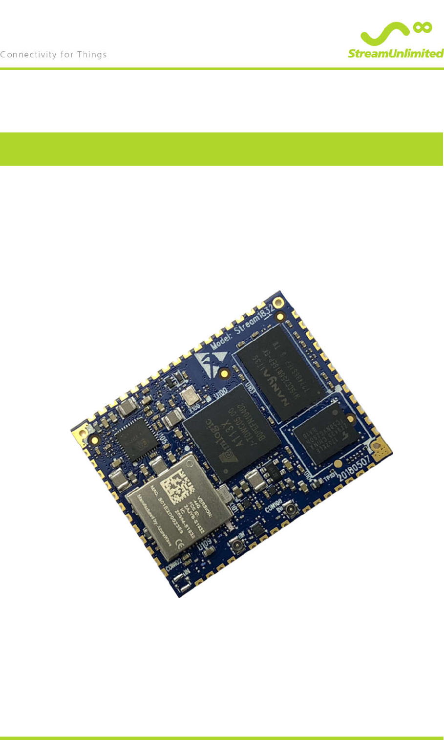
Stream1832
Network Audio Streaming Module
Version: 1.0
Authors: T. Gruber, C. Apel
Reviewer:
Date: November 22, 2018

2AJYB-S1832 FCC IC Instruction For Use
November 22, 2018
Page 2 of 10 StreamUnlimited Engineering GmbH
Gutheil-Schoder-G. 10, 1100 Vienna, Austria
T +43-1-667 2002, F +43-1-667 2002 4401
1. Table of Content
1. Table of Content ............................................................................................... 2
2. Document History ............................................................................................. 3
Confidentiality Notice ....................................................................................................... 4
Copyright Notice .............................................................................................................. 4
Document Version Management Notice ........................................................................... 4
3. Module labelling................................................................................................ 5
4. Product labelling............................................................................................... 5
5. Instruction for use requirements..................................................................... 5
6. Antenna type and connections ....................................................................... 8
7. Output Power configuration ............................................................................ 9
8. EMC application notes ................................................................................... 10

2AJYB-S1832 FCC IC Instruction For Use
November 22, 2018
Page 3 of 10 StreamUnlimited Engineering GmbH
Gutheil-Schoder-G. 10, 1100 Vienna, Austria
T +43-1-667 2002, F +43-1-667 2002 4401
2. Document History
No. Primary Author(s) Description of Version Date Completed
0.1 T. Gruber Initial version 2018-05-28
0.2 C. Apel minor update 2018-10-04
1.0 C. Apel update transmit power
configuration 2018-11-22

2AJYB-S1832 FCC IC Instruction For Use
November 22, 2018
Page 4 of 10 StreamUnlimited Engineering GmbH
Gutheil-Schoder-G. 10, 1100 Vienna, Austria
T +43-1-667 2002, F +43-1-667 2002 4401
Confidentiality Notice
The information contained in this document is confidential information property of
StreamUnlimited Engineering GmbH. No part of this document may be used or reproduced
without written permission.
Copyright Notice
All rights reserved. No part of this work covered by the owners copyright may be reproduced or
copied in any form or by any means (graphic, electronic or mechanical, including photocopying,
recording, taping or information retrieval systems) without written permission.
Document Version Management Notice
Updates of this document will be done without notice. The latest document version is available
on request.
2AJYB-S1832 FCC IC Instruction For Use
November 22, 2018
Page 5 of 10 StreamUnlimited Engineering GmbH
Gutheil-Schoder-G. 10, 1100 Vienna, Austria
T +43-1-667 2002, F +43-1-667 2002 4401
3. Module labelling
Module label already contains the necessary certification IDs. The printing must remain visible
when the module is mounted. Should the module printing be covered e.g. by a heatsink, then an
additional label must be applied which contains the same IDs.
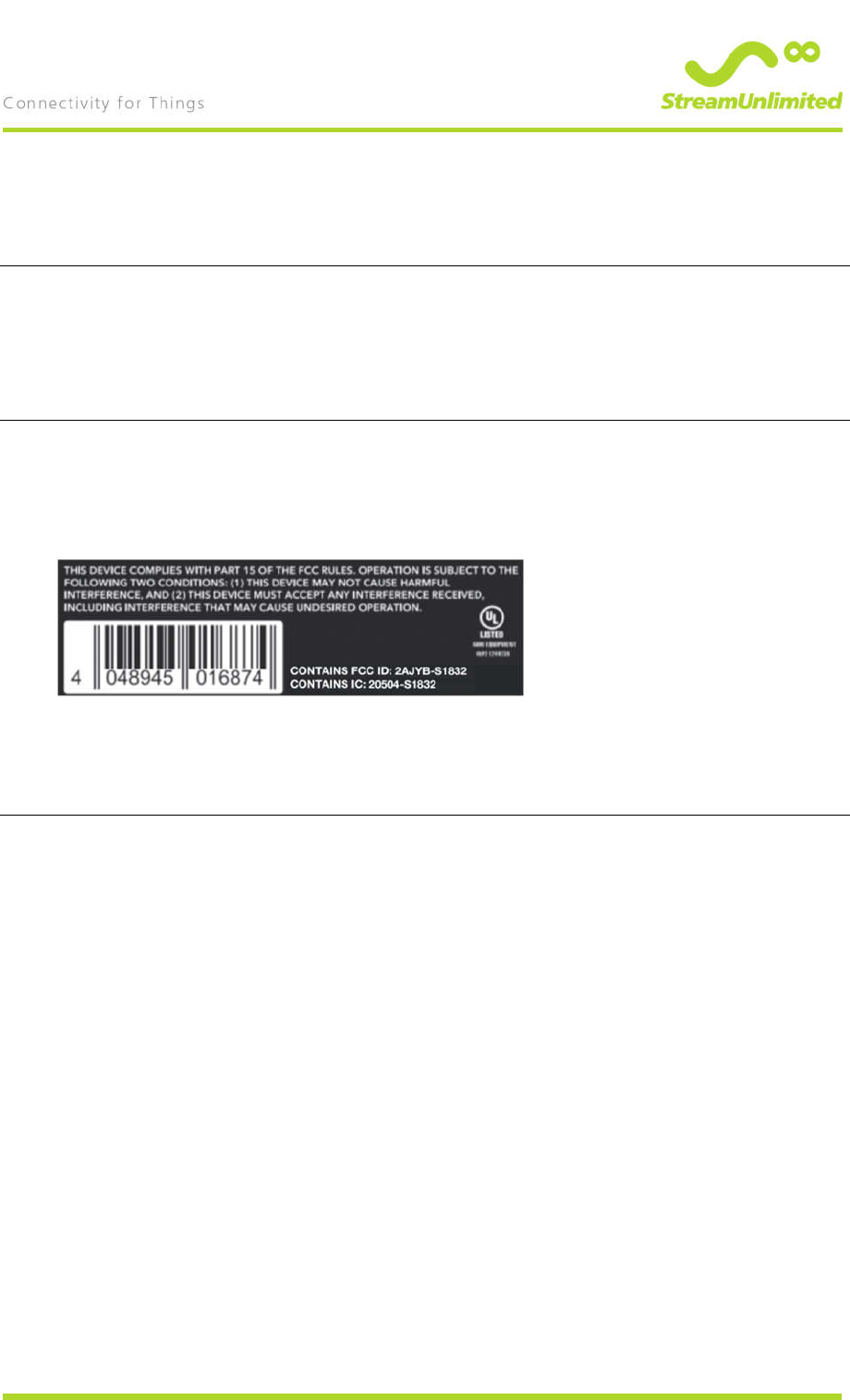
4. Product labelling
Product label must contain following text:
“CONTAINS FCC ID: 2AJYB-S1832”
“CONTAINS IC: 20504-S1832”
See below example for reference
5. Instruction for use requirements
Instructions for use must contain warnings and customer information, see next two pages for
detailed text

2AJYB-S1832 FCC IC Instruction For Use
November 22, 2018
Page 6 of 10 StreamUnlimited Engineering GmbH
Gutheil-Schoder-G. 10, 1100 Vienna, Austria
T +43-1-667 2002, F +43-1-667 2002 4401
Declaration of Conformity
This device complies with Part 15 of the FCC Rules.
Operation is subject to the following two conditions:
(1) this device may not cause harmful interference, and
(2) this device must accept any interference received, including interference that may cause
undesired operation.
This product does not contain any user serviceable components. Any unauthorized product
changes or modifications will invalidate warranty and all applicable regulatory certifications and
approvals, including authority to operate this device.
Warning
This equipment has been tested and found to comply with the limits for a Class B digital device,
pursuant to Part 15 of the FCC Rules. These limits are designed to provide reasonable
protection against harmful interference in a residential installation. This equipment generates,
uses and can radiate radio frequency energy and, if not installed and used in accordance with
the instructions, may cause harmful interference to radio communications. However, there is no
guarantee that interference will not occur in a particular installation. If this equipment does cause
harmful interference to radio or television reception, which can be determined by turning the
equipment off and on, the user is encouraged to try to correct the interference by one or more of
the following measures:
Reorient or relocate the receiving antenna.
Increase the separation between the equipment and receiver.
Connect the equipment into an outlet on a circuit different from that to which the receiver
is connected.
Consult the dealer or an experienced radio /TV technician for help.
Caution:
Changes or modifications not expressly approved by the party responsible for compliance could
void the user's authority to operate the equipment.
Operations in the 5.15 – 5.25GHz band are restricted to indoor usage only.
RF Exposure Requirements
To comply with FCC requirements, a minimum separation distance of 20cm (8 inches) is
required between the equipment and the body of the user or nearby persons.
Canada:
This Class B digital apparatus complies with Canadian ICES-003 and RSS-247.
Operation is subject to the following two conditions:
(1) This device may not cause harmful interference, and
(2) This device must accept any interference received, including interference that may cause
undesired operation.
The installer of this radio equipment must ensure that the product is located such that it does not
emit RF field in excess of Health Canada limits for the general population: consult Safety Code
6, obtainable from Health Canada´s We site www.hc-sc.gc.ca/rpb.
As mentioned before, the installer cannot control the antenna orientation. However, they could
place the complete product in a way that causes the problem mentioned above.
The device for operation in the band 5150-5250 MHz is only for indoor use to reduce the
potential for harmful interference to co-channel mobile satellite systems.
Be advices that high-power radars are allocated as primary users (i.e. priority users) of the
bands 5250-5350MHz and 5650-5850MHz and that these radars could cause interference
and/or damage to LE-LAN devices.
Changes or modifications not expressly approved by the party responsible for compliance could

2AJYB-S1832 FCC IC Instruction For Use
November 22, 2018
Page 7 of 10 StreamUnlimited Engineering GmbH
Gutheil-Schoder-G. 10, 1100 Vienna, Austria
T +43-1-667 2002, F +43-1-667 2002 4401
void the user's authority to operate the equipment.
Cet appareil numérique de classe B est conforme aux normes NMB-003 et CNR-247 en vigueur
au Canada.
Son fonctionnnement est soumis aux deux conditions suivantes : (1) Cet appareil ne doit pas
créer d'interférences nuisibles. (2) Cet appareil doit tolérer toutes les interférences reçues, y
compris les interférences pouvant entraîner un fonctionnement indésirable. L'installateur du
présent matériel radio doit veiller à ce que le produit soit placé ou orienté de manière à n'émettre
aucun champ radioélectrique supérieur aux limites fixées pour le grand public par le ministère
fédéral Santé Canada ; consultez le Code de sécurité 6 sur le site Web de Santé Canada à
l'adresse : www.hc-sc.gc.ca/rpb. Comme indiqué auparavant, l'installateur ne peut pas contrôler
l'orientation de l'antenne. Il peut néanmoins placer le produit tout entier de manière à provoquer
le problème décrit ci-dessus.
Les dispositifs fonctionnant dans la bande 5150-5250 MHz sont réservés uniquement pour une
utilisation à l'intérieur afin de réduire les risques de brouillage préjudiciable aux systèmes de
satellites mobiles utilisant les mêmes canaux. Les utilisateurs de radars de haute puissance sont
désignés utilisateurs principaux (c.-à-d., qu'ils ont la priorité) pour les bandes 5250-5350 MHz et
5650-5850 MHz et que ces radars pourraient causer du brouillage et/ou des dommages aux
dispositifs LAN-EL.
2AJYB-S1832 FCC IC Instruction For Use
November 22, 2018
Page 8 of 10 StreamUnlimited Engineering GmbH
Gutheil-Schoder-G. 10, 1100 Vienna, Austria
T +43-1-667 2002, F +43-1-667 2002 4401
6. Antenna type and connections
Stream1832 provides two antenna ports via microwave coaxial connectors.
Antennas with 50 Ohm characteristic impedance must be connected to each microwave coaxial
connector via coaxial RF cable. No external amplifier or tuning circuitry must be used.
Stream1832 was certified for FCC and IC compliance using following antennas:
Type of antenna: Molex 146153 (recommended)
Frequency band: 2400 – 2500 MHz 5150 – 5850 MHz
Return Loss: < -10 dB
Peak Gain (Max): 3.2 dBi 4.25 dBi
Average Total Efficiency: > 78% > 79%
Impedance: 50 Ohm
Cable Length *): 50mm, 100mm, 150mm, 200mm, 250mm, 300mm
Type of antenna: Molex 204281
Frequency band: 2400 – 2500 MHz 5150 – 5850 MHz
Return Loss: < -10 dB
Peak Gain (Max): 2.2 dBi 3.5 dBi
Average Total Efficiency: > 68% > 70%
Impedance: 50 Ohm
Cable Length *): 50mm, 100mm, 150mm, 200mm, 250mm, 300mm
Type of antenna: 2J-Antennas 2JMAS05c
Frequency band: 2400 – 2500 MHz 5100 – 5900 MHz
Antenna gain: 3 dBi
VSWR: < 1.5:1
Impedance: 50 Ohm
Cable Length: 150mm
If using Stream1832 with antennas that exceed the gain of above antenna types, FCC and IC
compliance must be re-evaluated and power settings adapted.

2AJYB-S1832 FCC IC Instruction For Use
November 22, 2018
Page 9 of 10 StreamUnlimited Engineering GmbH
Gutheil-Schoder-G. 10, 1100 Vienna, Austria
T +43-1-667 2002, F +43-1-667 2002 4401
7. Output Power configuration
To comply with Part 15 of the FCC Rules and Canadian ICES-003 and RSS-247, output power
must be limited to following levels by permanent configuration setting. Below levels refer to
firmware settings in dBm.
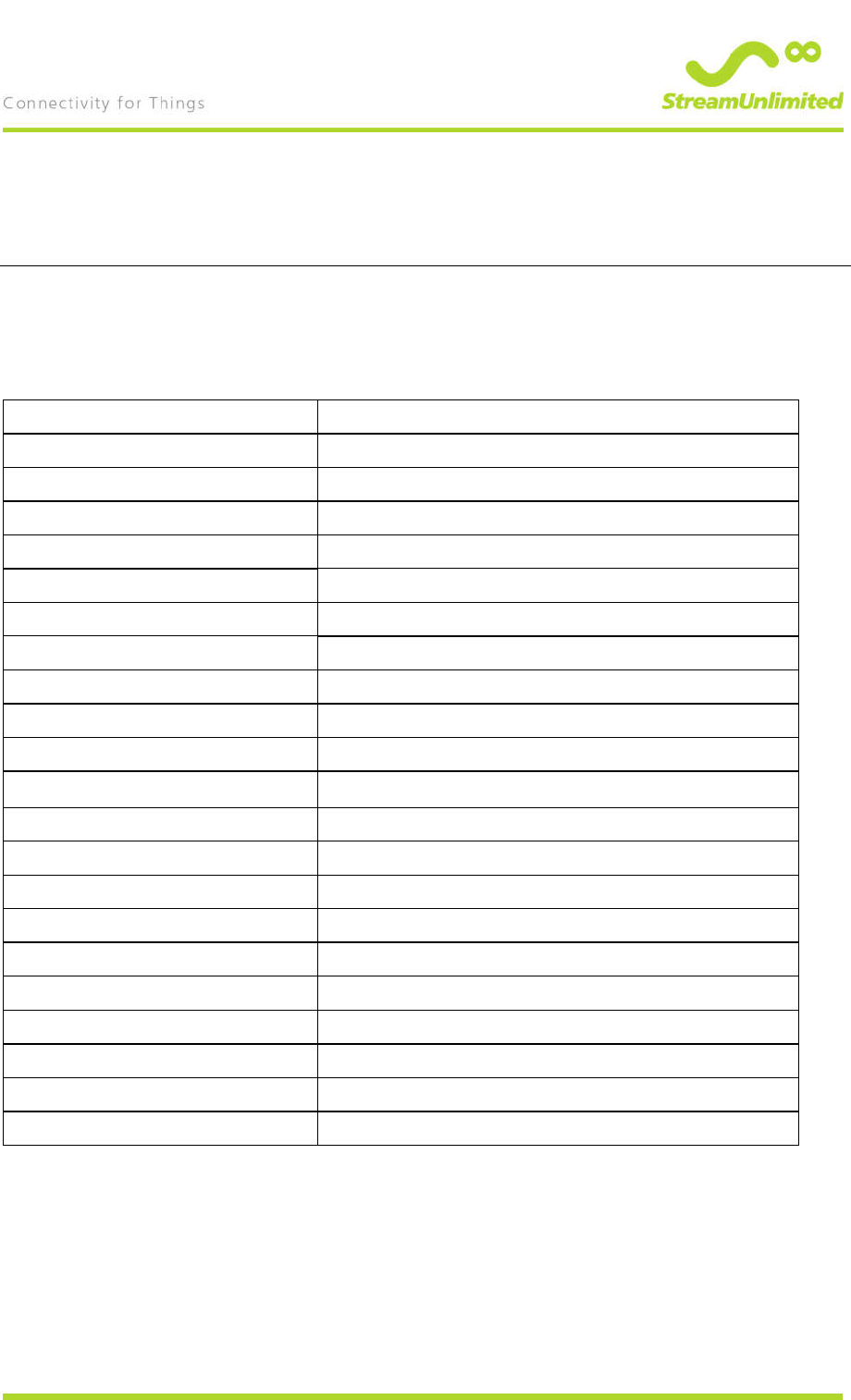
Frequency band Channel width modulation dBm setting
2.4 GHz 20MHz DSSS 17
2,4 GHz 20 MHz OFDM 11
2,4 GHz 40 MHz OFDM 12
5 GHz 20 MHz OFDM 15
5 GHz 40 MHz OFDM 12
5 GHz 80 MHz OFDM 10
Bluetooth 4.2 output level setting: class 2 (4dBm)
.
2AJYB-S1832 FCC IC Instruction For Use
November 22, 2018
Page 10 of 10 StreamUnlimited Engineering GmbH
Gutheil-Schoder-G. 10, 1100 Vienna, Austria
T +43-1-667 2002, F +43-1-667 2002 4401
8. EMC application notes
Spurious emissions are highly dependant on the carrier board design. Legal compliance must be
verified on product level.
Below recommendations should be taken into account to ensure legal compliance of the product
application :
Use a GND plane underneath the module.
Use series resistors in all low speed interface lines, values need to be chosen depending on
signal frequency and length of signal lines on application board.
Use common mode signal filters in USB data lines, e.g. Wuerth 744232161.
Do not use vias in high speed interface lines such as USB and Ethernet.
Route high speed interface lines differentially and leave several mm gap to other signal lines
when possible.
Route following interfaces as short as possible, preferably on inner layers:
External RMII interface
I2S interfaces, especially clock lines
PDM interface, especially clock lines
Make sure any interface which is not needed for your application is disabled in software.
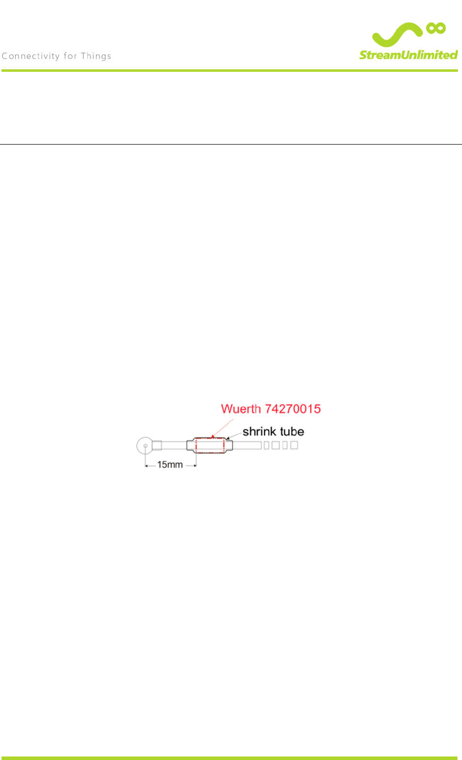
Since the WLAN antennas also radiate undesired disturbances the use of a Ferrite on the
antenna cables is recommended, see below diagram for details: