Strix Systems ACCESS-ONE 802.11 a/b/g Wireless Access Point User Manual Quick Start DE

Strix Systems, Inc. 802.11 a/b/g Wireless Access Point Quick Start DE

Contents

Access One Quick Start Guide

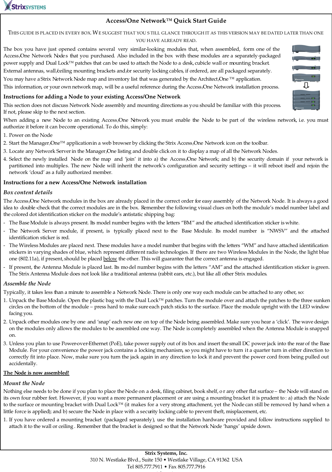
        Strix Systems, Inc. 310 N. Westlake Blvd., Suite 150 • Westlake Village, CA 91362  USA Tel 805.777.7911 • Fax 805.777.7916 www.strixsystems.com Access/One Network™ Quick Start Guide THIS GUIDE IS PLACED IN EVERY BOX. WE SUGGEST THAT YOU S TILL GLANCE THROUGH IT AS THIS VERSION MAY BE DATED LATER THAN ONE YOU HAVE ALREADY READ. The box you have just opened contains several  very similar-looking modules that, when assembled,  form one of the Access/One Network Node s that  you  purchased. Also included in the box  with these modules are a separately-packaged power supply and Dual Lock™ patches that can be used to attach the Node to a desk, cubicle wall or mounting bracket. External antennas, wall/ceiling mounting brackets and/or security locking cables, if ordered, are all packaged separately.  You may have a Strix Network Node map and inventory list that was generated by the Architect/One ™ application. This information, or your own network map, will be a useful reference during the Access/One Network installation process.  Instructions for adding a Node to your existing Access/One Network This section does not discuss Network Node assembly and mounting directions as you should be familiar with this process. If not, please skip to the next section. When  adding a  new  Node to an existing Access/One Network you must  enable  the Node to be part of  the wireless network, i.e. you must authorize it before it can become operational. To do this, simply: 1. Power on the Node 2. Start the Manager/One™ application in a web browser by clicking the Strix Access/One Network icon on the toolbar. 3. Locate any Network Server in the Manager/One listing and double click on it to display a map of all the Network Nodes. 4. Select the newly installed  Node on the map  and ‘join’ it into a) the Access/One Network; and b) the security domain if  your network is partitioned into multiples. The new Node will inherit the network’s configuration and security settings – it will reboot itself and rejoin the network ‘cloud’ as a fully authorized member. Instructions for a new Access/One Network installation Box content details The Access/One Network modules in the box are already placed in the correct order for easy assembly  of the Network Node. It is always a good idea to  double -check that the correct modules are in the box. Remember the following visual clues on both the module’s model number label and the colored dot identification sticker on the module’s antistatic shipping bag: - The Base Module is always present. Its model number begins with the letters “BM” and the attached identification sticker is white. - The  Network  Server module, if present, is  typically  placed next to the  Base  Module.  Its model number  is “NWSV” and the attached identification sticker is red. - The Wireless Modules are placed next. These modules have a model number that begins with the letters “WM” and have attached identification stickers in varying shades of blue, which represent different radio technologies. If  there are two Wireless Modules in the Node, the light blue one (802.11a), if present, should be placed below the other. This will guarantee that the correct antenna is engaged. - If present, the Antenna Module is placed last. Its mo del number begins with the letters “AM” and the attached identification sticker is green. The Strix Antenna Module does not look like a traditional antenna (rabbit ears, etc.), but like all other Strix modules. Assemble the Node Typically, it takes less than a minute to assemble a Network Node. There is only one way each module can be attached to any other, so: 1. Unpack the Base Module. Open the plastic bag with the Dual Lock™ patches. Turn the module over and attach the patches to the three sunken circles on the bottom of the module – press hard to make sure each patch sticks to the surface. Place the module upright with the LED window facing you.  2. Unpack other modules one by one  and ‘snap’ each new one  on top of the Node being assembled. Make sure you hear a ‘click’. The wave design on the modules only allows the modules to be assembled one way. The Node is completely assembled when the Antenna Module is snapped on.  3. Unless you plan to use Power-over-Ethernet (PoE), take power supply out of its box and insert the small DC power jack into the rear of the Base Module. For your convenience the power jack contains a locking mechanism, so you might have to turn it a quarter turn in either direction to correctly fit into place. Now, make sure you turn the jack again in any direction to lock it and prevent the power cord from being pulled out accidentally. The Node is now assembled!   Mount the Node Nothing else needs to be done if you plan to place the Node on a desk, filing cabinet, book shelf, o r any other flat surface – the Node will stand on its own four rubber feet. However, if you want a more permanent placement or are using a mounting bracket it is prudent to : a) attach the Node to the surface or mounting bracket with Dual Lock™ (it makes for a very strong attachment, yet the Node can still be removed by hand when a little force is applied); and b) secure the Node in place with a security locking cable to prevent theft, misplacement, etc.  1. If you have ordered a mounting bracket  (packaged separately), use the installation hardware provided and follow instructions supplied  to attach it to the wall or ceiling . Remember that the bracket is designed so that the Network Node ‘hangs’ upside down.
      - 2 -                                                                                                  Strix Systems, Inc. 310 N. Westlake Blvd., Suite 150 • Westlake Village, CA 91362  USA Tel 805.777.7911 • Fax 805.777.7916 www.strixsystems.com 2. Place the mating side of the Dual Lock™ patches supplied in this box on the desk, cabinet, book shelf, bracket, etc. Included in the package is a Node footprint with appropriate cutouts for easy placement of the patches. Make sure that the surface is clean and you press hard enough for the patches to stick. Align the assembled Node with the Dual Lock™ patches and apply light pressure to engage.  3. If you ordered the security locking cable (packaged separately), with the Node facing you thread the  cable through the opening on the left side of every module starting with  the Antenna  Module and ending with the Base Module, and secure it  to a  permanent object  such as a bracket, wall, desk, etc. The Node is secure and ready to be plugged in! Note: Strix external antennas, if purchased, can stand freely on any horizontal surface or be attached to it with the Dual Lock™ patches.  Power up the Node An assembled Node may have zero , one or four Ethernet ports on the rear of its Base Module. If no Ethernet ports are present, just plug the power cord into the nearest wall outlet. When at least one Ethernet port is present, the one closest to the power jack on the rear of the module supports PoE (this is marked on the back panel). The power jack and/or PoE could be used as power sources in this case.  Attach Ethernet cables (not supplied) to the appropriate port(s) and turn the power on. The front of each  module has a single multi-color LED. During the normal Node initialization process the Base Module LED will initially turn “orange” and almost immediately turn solid “green.” The LEDs on all other modules will blink “green” for a short period of time and then turn solid “green.”  The Node is now operational! Warnings: - Access/One  Network  automatically obtains the necessary IP addresses from a DHCP server.  This  must be present  on your network  and accessible  by the Node . - The Strix  Network Node will recognize  if  a  non-Strix  external 802.11a antenna  is attached to it and  will shut down the corresponding radio. This is an FCC requirement. - If any module’s LED is ever solid  “orange” or continuously goes through the startup sequence (orange, blinking green, orange…), please consult your User’s Guide or contact your local Strix representative for assistance. - Each Ethernet port (on the rear of the Node) has two small LEDs (link status and data traffic activity). These must be solid or blinking “green” for the port to operate properly. Install Manager/One utility  In most cases there is no need to manage individual Network Nodes in a Strix Access/One Network. The network is managed as a whole using the Strix Manager/One web application. However, before doing anything else you must first download and install the Strix Manager/One utility:  1. Point your web browser to the support page at www.strixsystems.com and follow the Manager/One download instructions. 2. Install the Manager/One  utility on  the  PC you will use for  network  management by executing the file you have just downloaded. Follow the installation instructions on the screen. When the installation process is completed, a Strix Access/One Network button will be placed on your browser’s top toolbar.  3. Click the Access/One Network button  in your browser  to see the Manager/One panel in that  shows a listing of  the discovered  Access/One Network wireless ‘cloud’.  4. Point your mouse to , and double-click on, any Network Server in the listing to start managing or monitoring the entire Access/One Network – the panel will disappear at this point. The first time you use Manager/One, the login name you must use is Admin, and the factory default password is also Admin. You will  be asked  to change the password the first time you login, and the network will remember your new password. You can now attach and login to any Access/One Network Node or module.  5. The first time you launch Manager/One, you will be asked to provide a name for your Access/One Network. Any new Strix Nodes discovered by the Manager/One in the future will be treated as rouge Nodes until you select and enable them within the network by authorizing  them. Keep in mind:  - DHCP and FTP servers must be accessible to your Access/One Network. A DHCP server automatically provides IP addresses to all Access/One Network Nodes while an FTP server allows you to download image upgrades when desired.  - At least one Network Server module must exist in the Access/One Network (shown on the Manager/One panel in your browser). It is a good idea to  make sure that a Node containing a Network Server module is operational before all others. - A single Network Server can support up to eight (8) Network Nodes in the Access/One Network. Using more than eight Nodes requires additional Network Servers. Network Security Strix Access/One Network Nodes present a consistent network connection to attached wireless users  (devices). Typically, these Nodes form a mix of wired and wireless interconnections, with  at least one Node  connected to a backbone/overlay wired network. This infrastructure is always secure – the Nodes are authenticated by the network and all wireless interconnections are encrypted ‘out-of-the-box’ using an AES cipher and a Strix private encryption key. The wireless users (devices) attached via  the wireless inter-Node connections are not allowed to connect  to your network until the wireless Node itself has been  authenticated by you and allowed to join the wireless ‘cloud’. User security policies are set within the Manager/One application screens. The User’s Guide complements the on-screen help information.
    Strix Systems, Inc. 310 N. Westlake Blvd., Suite 150 • Westlake Village, CA 91362  USA Tel 805.777.7911 • Fax 805.777.7916 www.strixsystems.com Radio Frequency Interference Requirements The enclosed devices are  restricted to indoor use due to their operation in the 5.15 to 5.25 GHz frequency range. FCC regulations require these products to be used indoors to reduce the potential for harmful interference.  High power radars are allocated as primary users of the 5.25 to 5.35 GHz and 5.65 to 5.85 GHz bands. These radar stations can cause interference with and/or damage to the enclosed devices. FCC Warning The enclosed devices comply with Part 15 of the FCC Rules.  Operation is subject to the following two conditions: 1. The devices may not cause harmful interference. 2. The devices must accept any interference received, including interference that may cause undesired operation.  This equipment has been tested and found to comply with the limits for a Class A or Class B digital device, pursuant to Part 15 of the FCC rules. These limits are designed to provide reasonable protection against harmful interference in a residential installation. This equipment generates, uses, and can radiate radio frequency energy and, if not installed and used in accordance with the instructions, may cause harmful interference to radio communications. There is no guarantee that interference will not occur in a particular installation. If this equipment does cause harmful interference to radio or television reception, which can be determined by turning the equipment off and on, the user is encouraged to try to correct the interference by one or more of the following measures: § Reorient or relocate the radio /TV receiving antenna.  § Increase the separation between the equipment and the radio/TV receiver.  § Connect the equipment into an outlet on a circuit different from that which the radio/TV receiver is connected.  § Consult the dealer or an experienced radio/TV technician for help.  Unless expressly approved by Strix Systems, Inc., modifications to this product could void the user's authority to operate the equipment.  RF Exposure Requirements To ensure compliance with FCC RF exposure requirements, the antenna used for the enclosed devices must be installed to provide a separation distance of at least 20 cm from all persons and must not be co-located or operating in conjunction with any other antenna or radio transmitter. Installers and end-users must follow the company’s installation instructions.

Navigation menu