Strix Systems ACCESS-ONE-32 802.11 a/g Wireless, Mesh Type Networking Device User Manual accessone userguide
Strix Systems, Inc. 802.11 a/g Wireless, Mesh Type Networking Device accessone userguide
UserManual.wiki
>
Strix Systems
>
ACCESS-ONE-32 User Manual
>
Users Manual Part IV
Contents
1.
User Guide Part 1
2.
User Guide Part 2
3.
User Guide Part 3
4.
User Guide Part 4
5.
Users Manual 5
6.
Users Manual Part I
7.
Users Manual Part II
8.
Users Manual Part III
9.
Users Manual Part IV
10.
Users Manual Part V
Users Manual Part IV
Navigation menu
Upload a User Manual
Namespaces
Wiki Guide
HTML
PDF
Info
Views
User Manual
Discussion / Help
Navigation
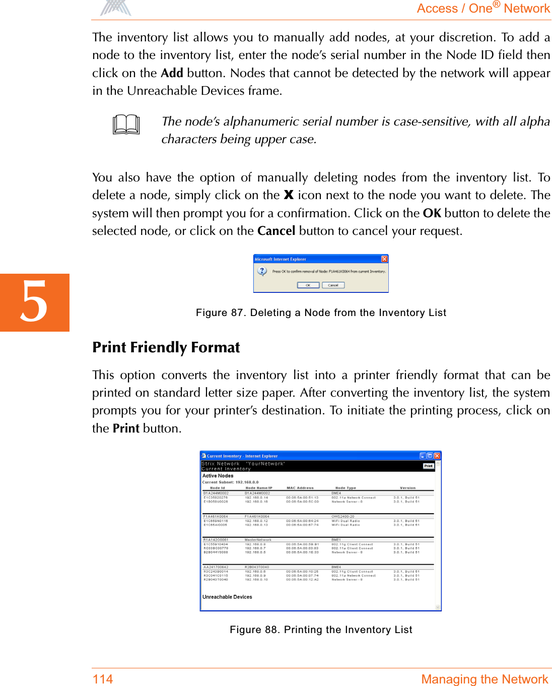
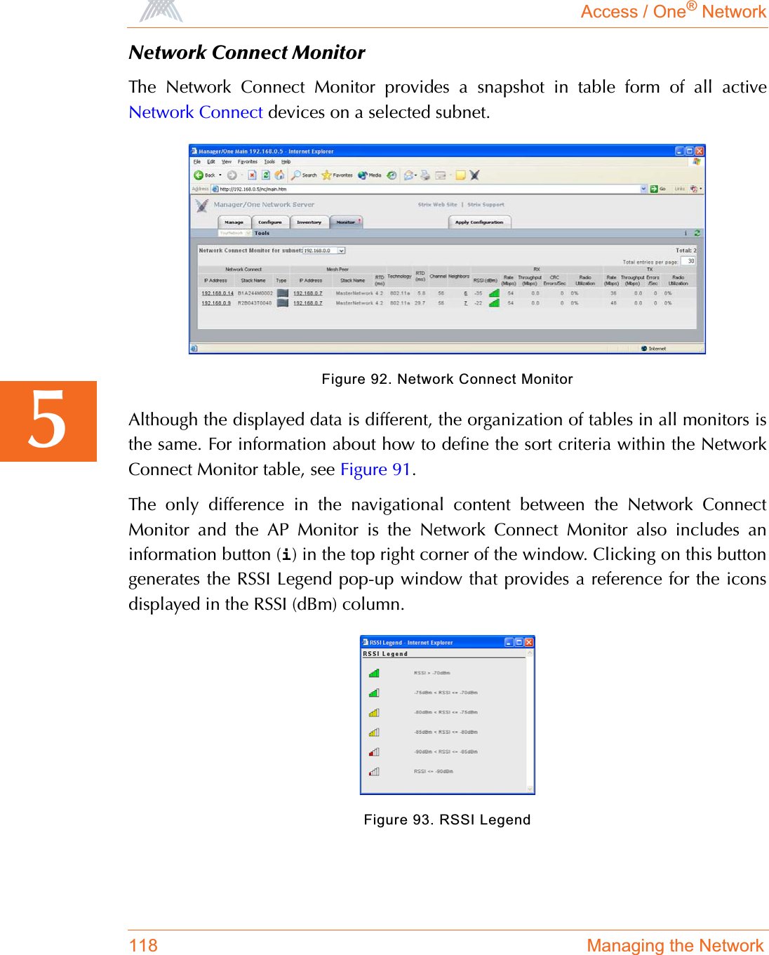
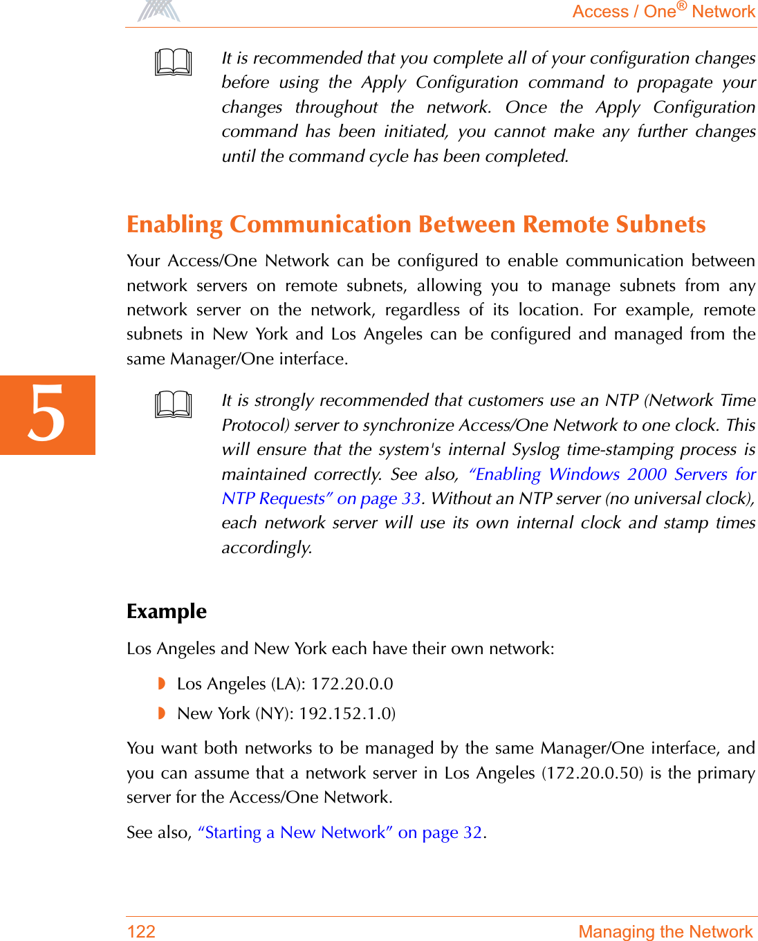
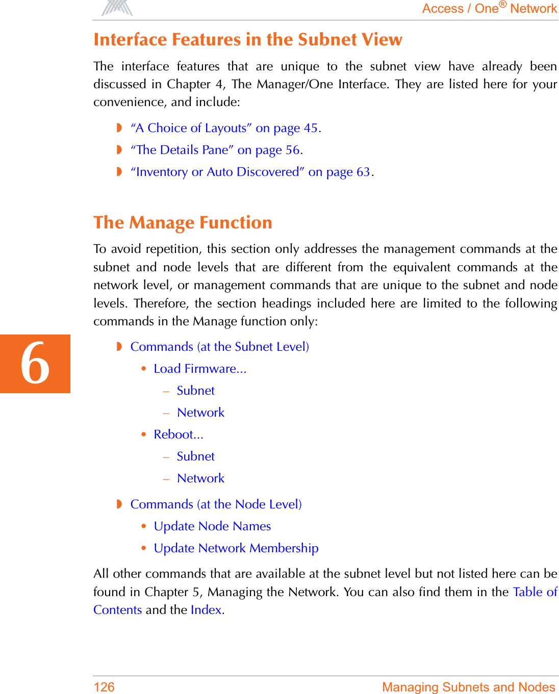
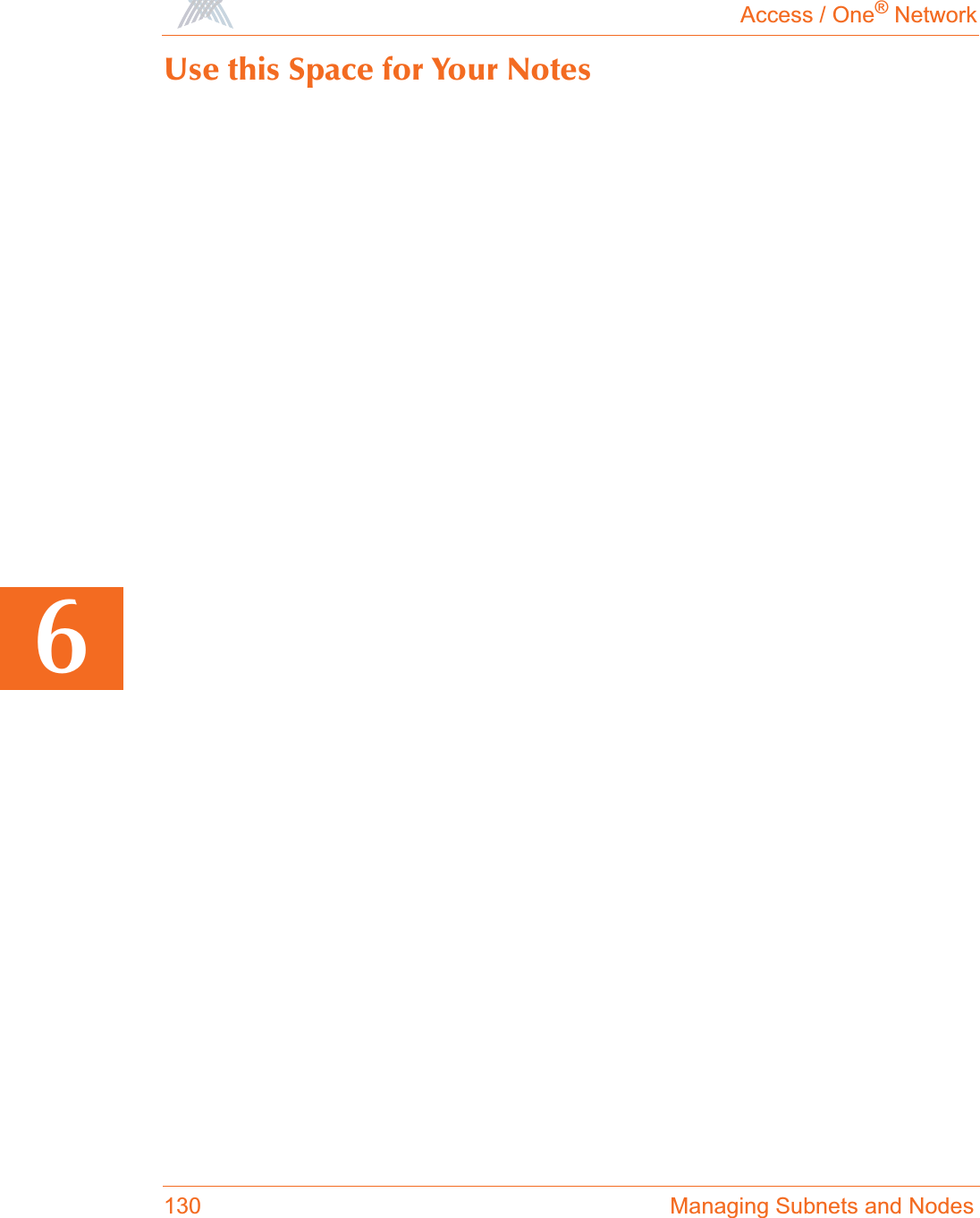
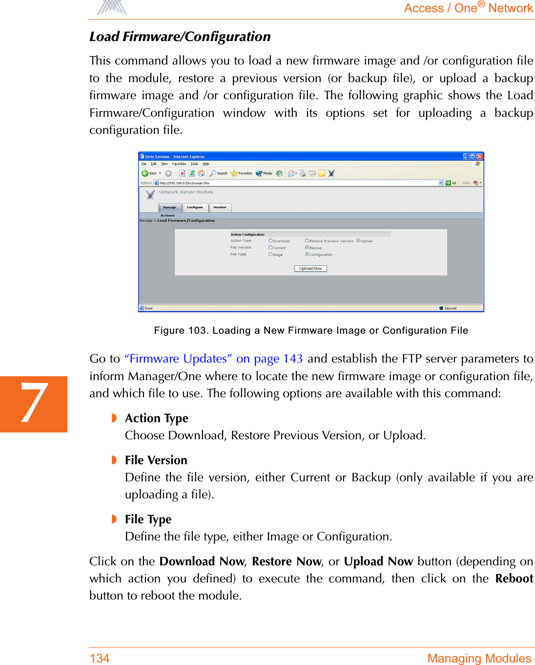
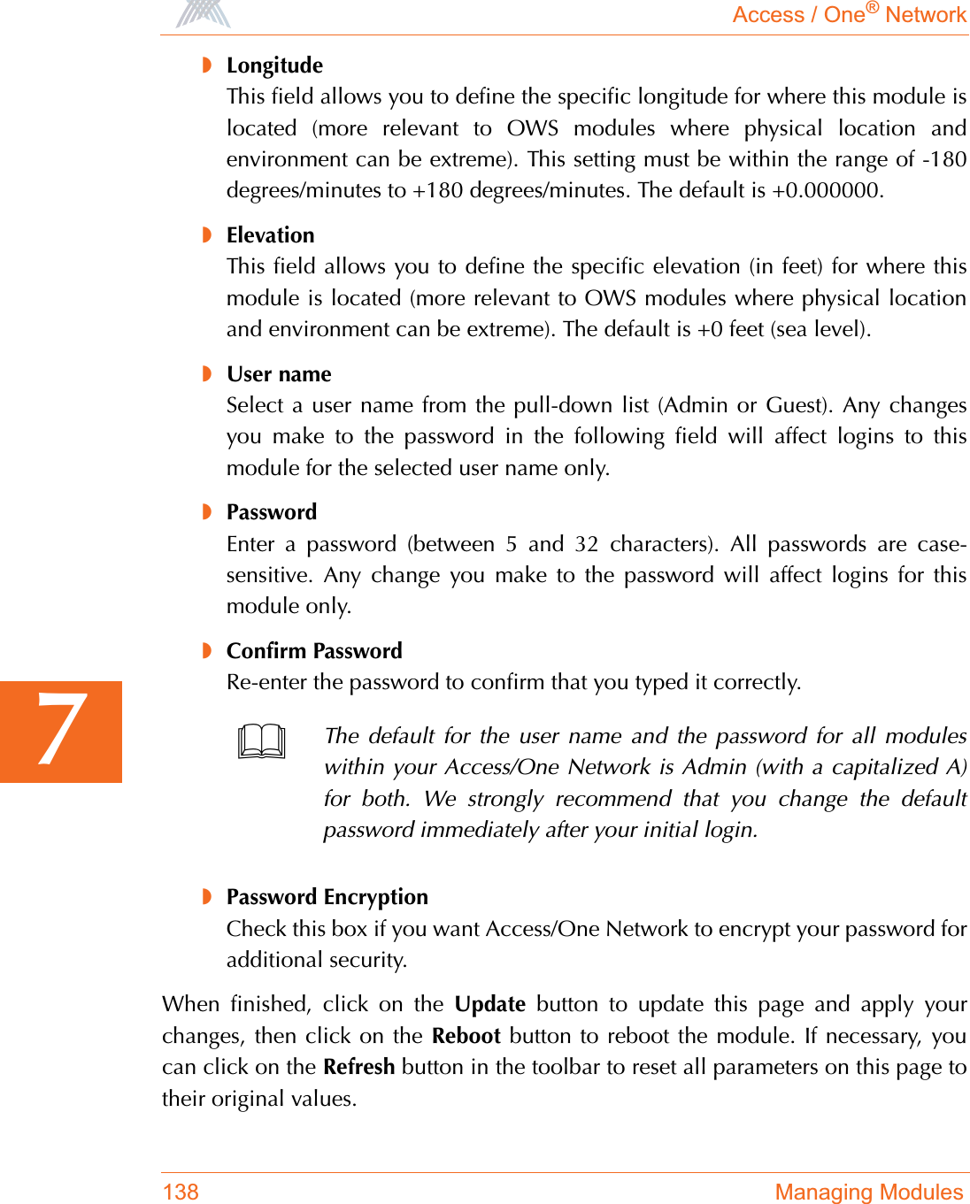
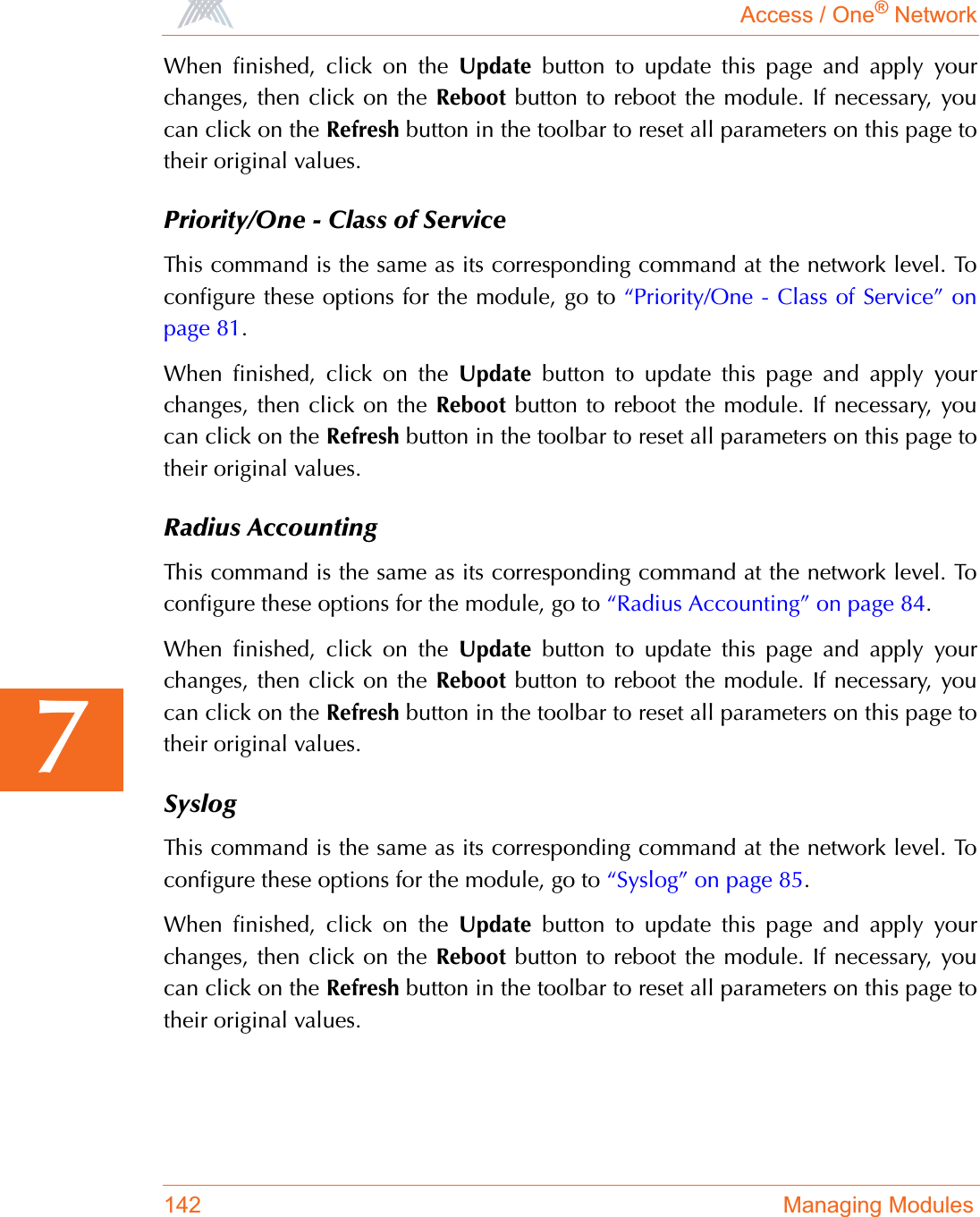
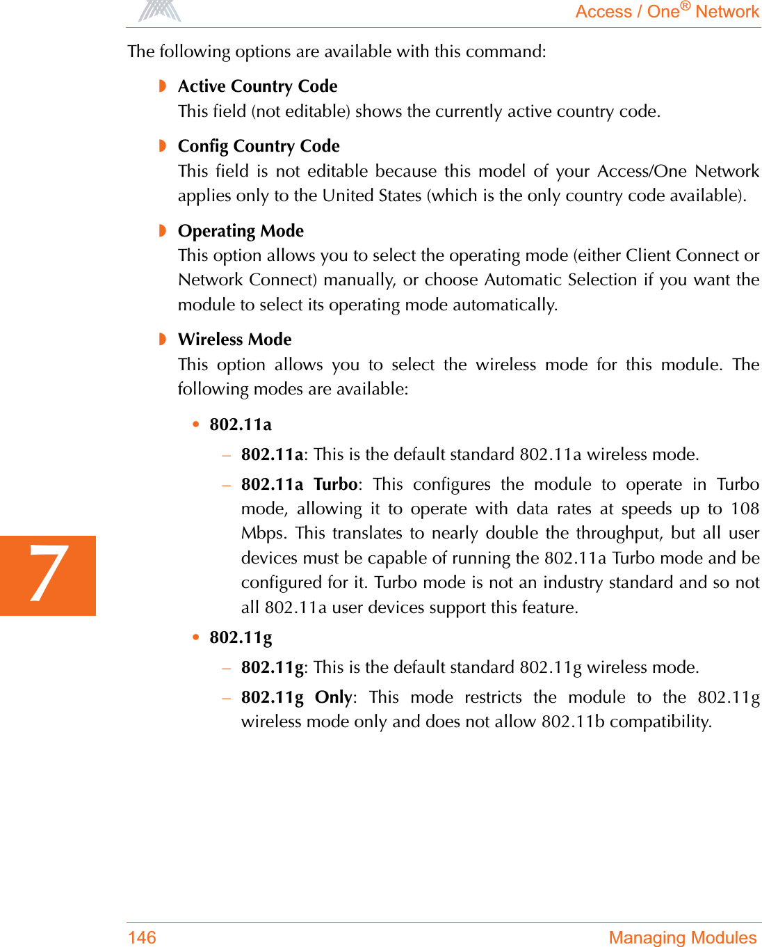
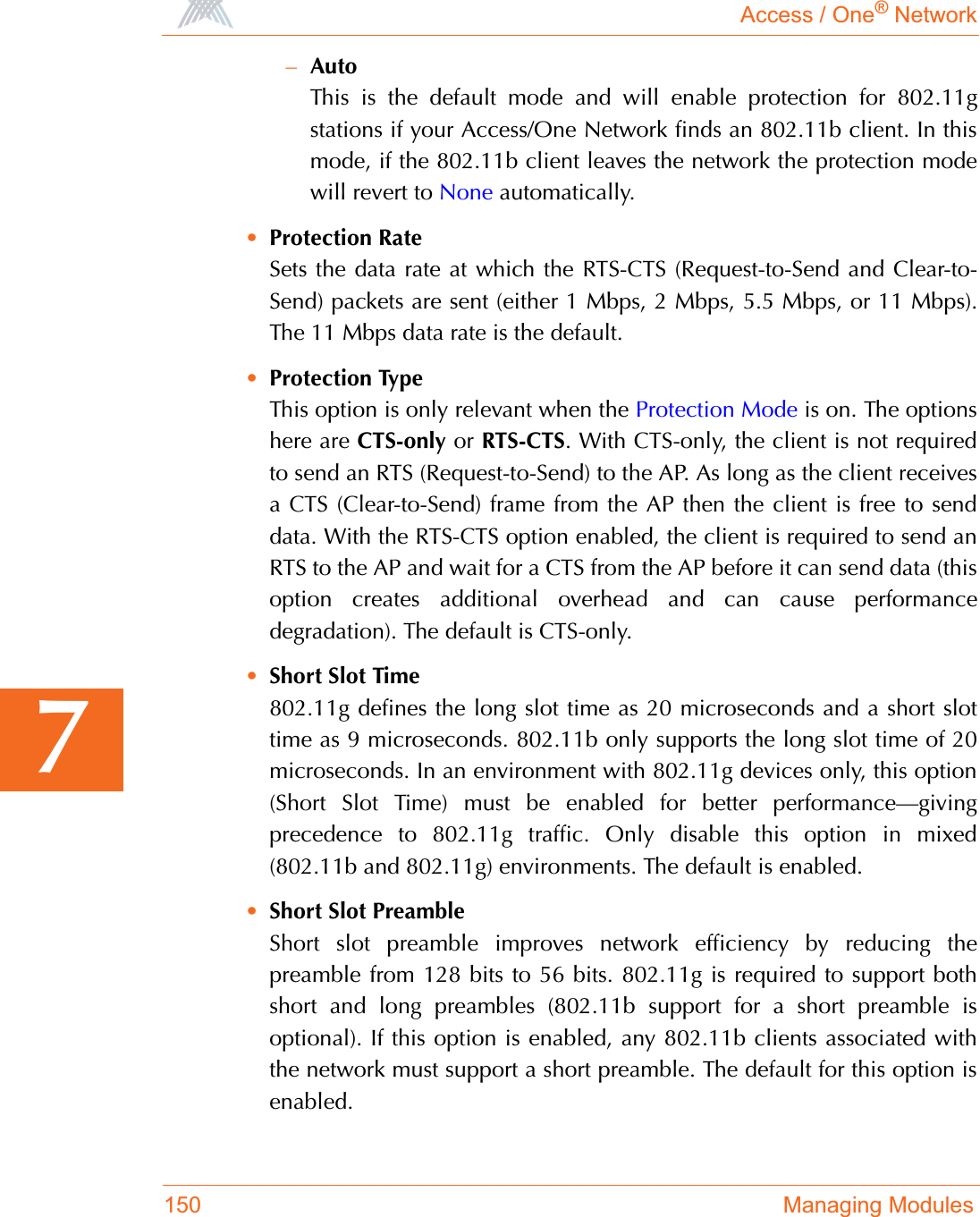
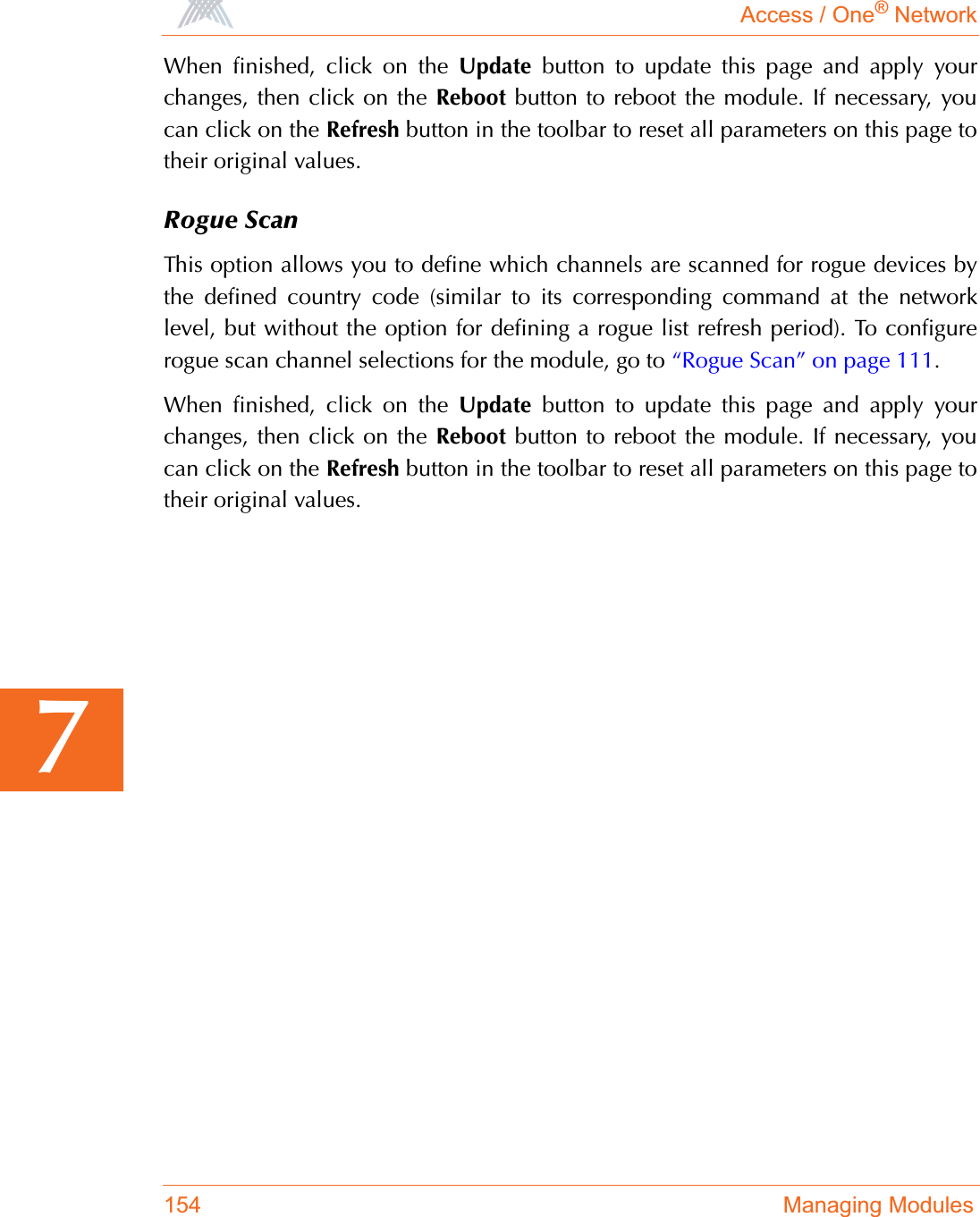
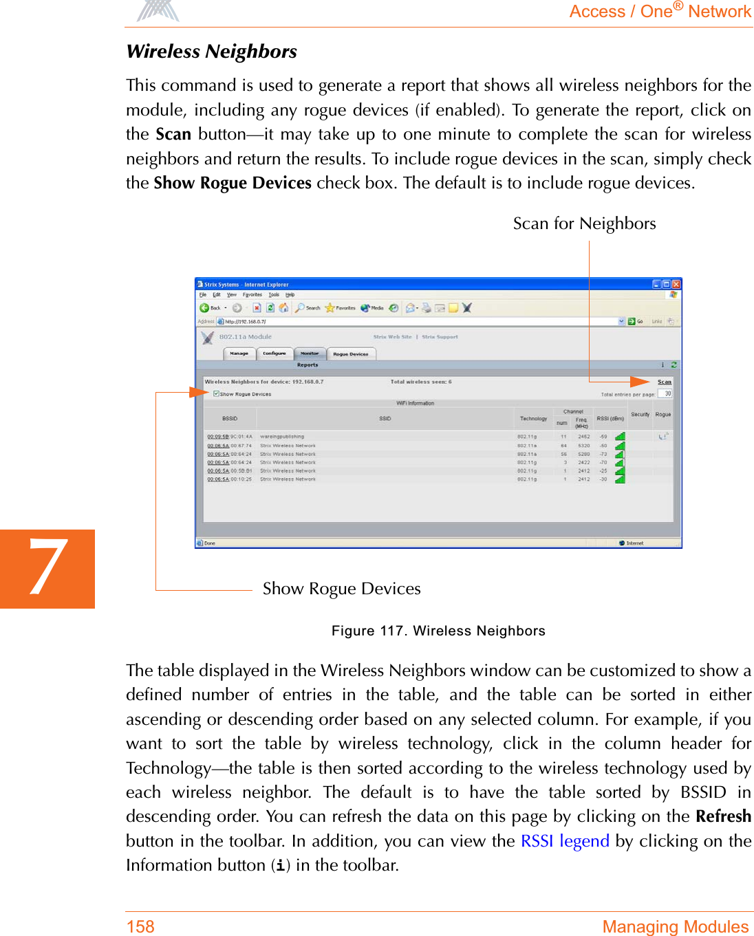
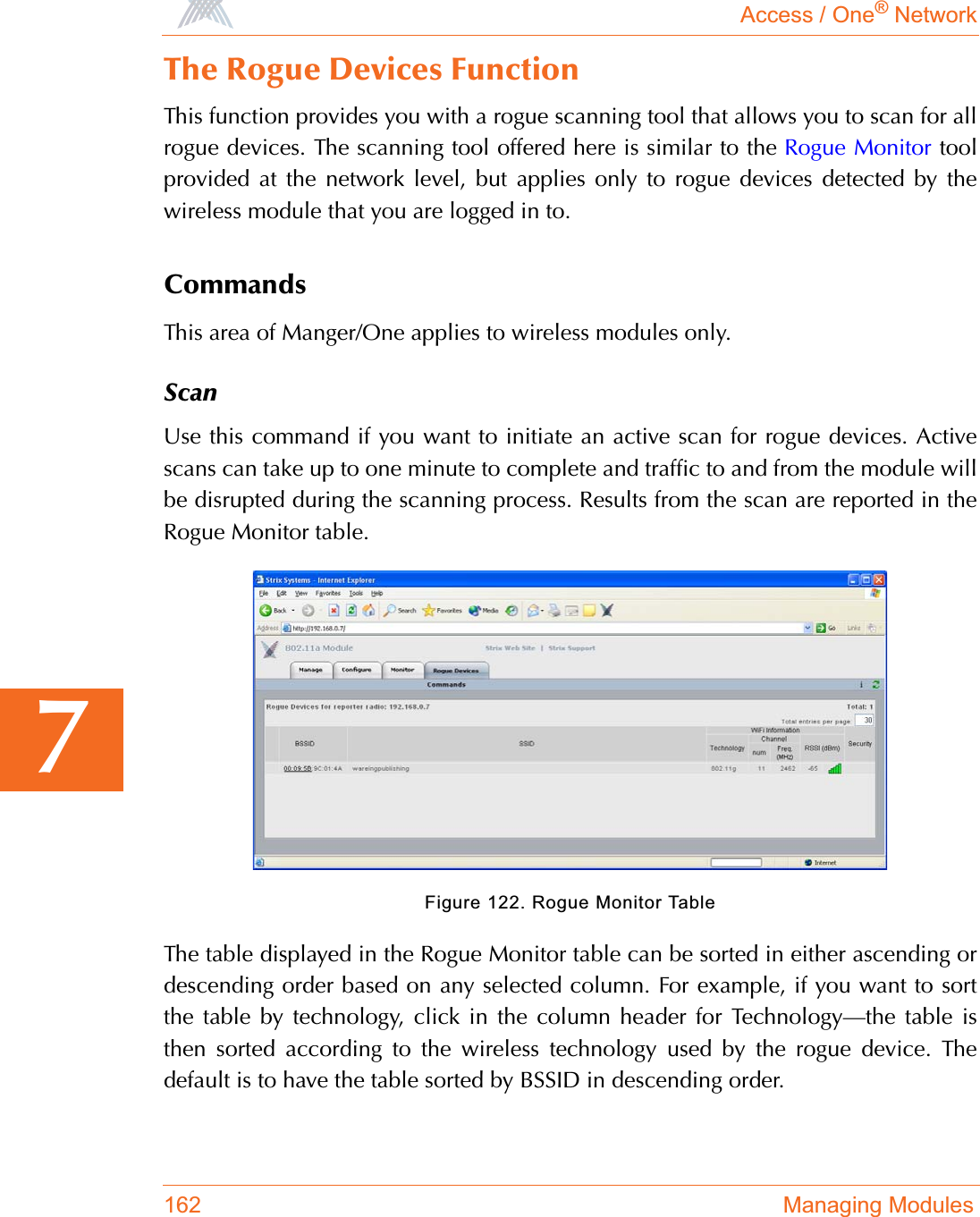

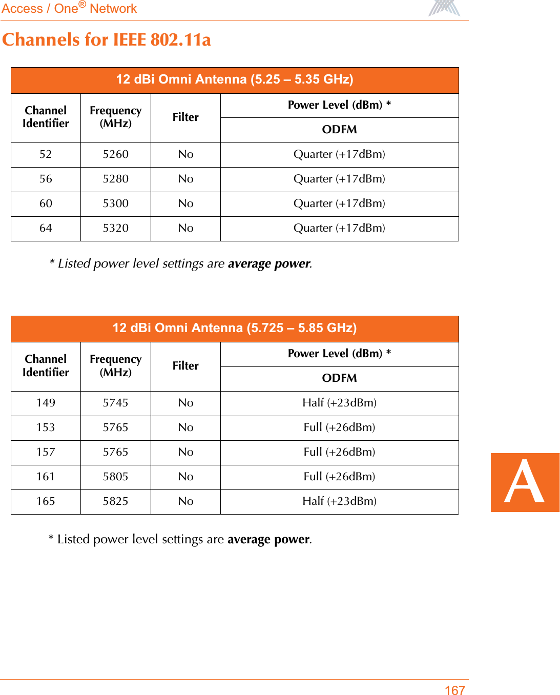
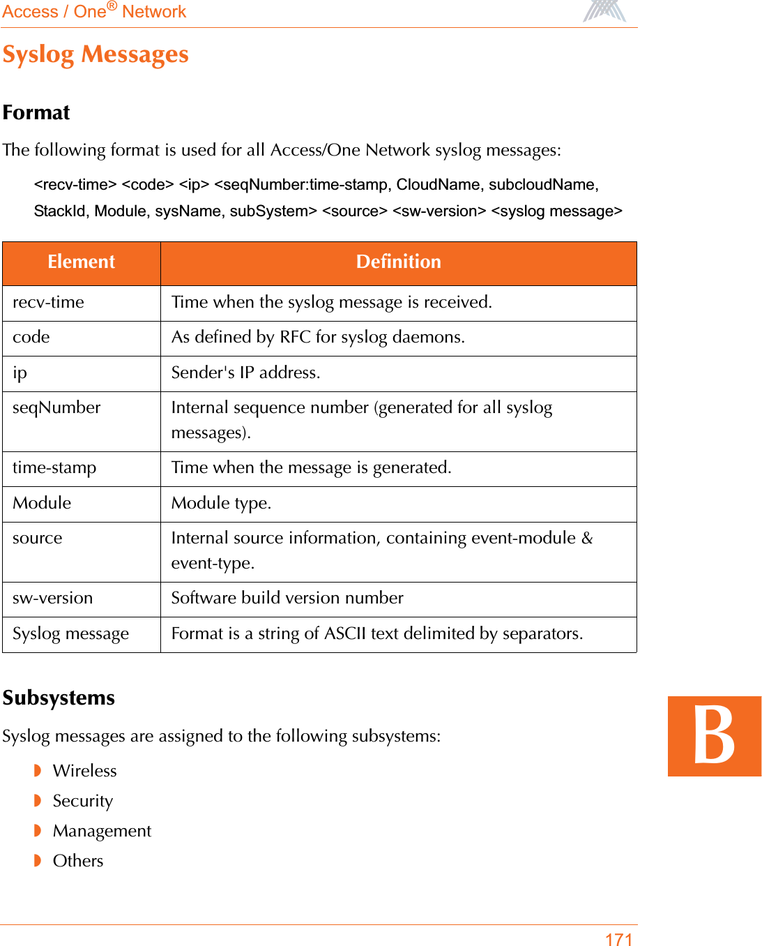
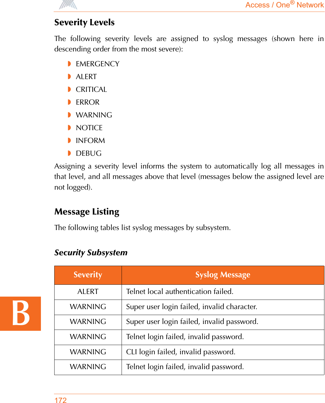
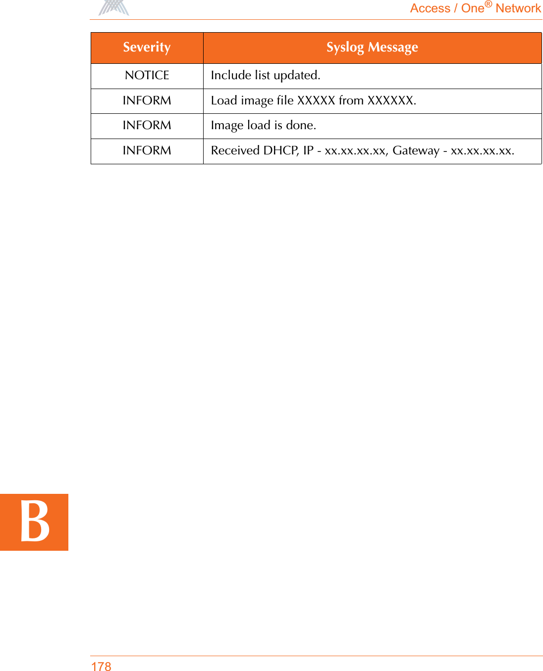
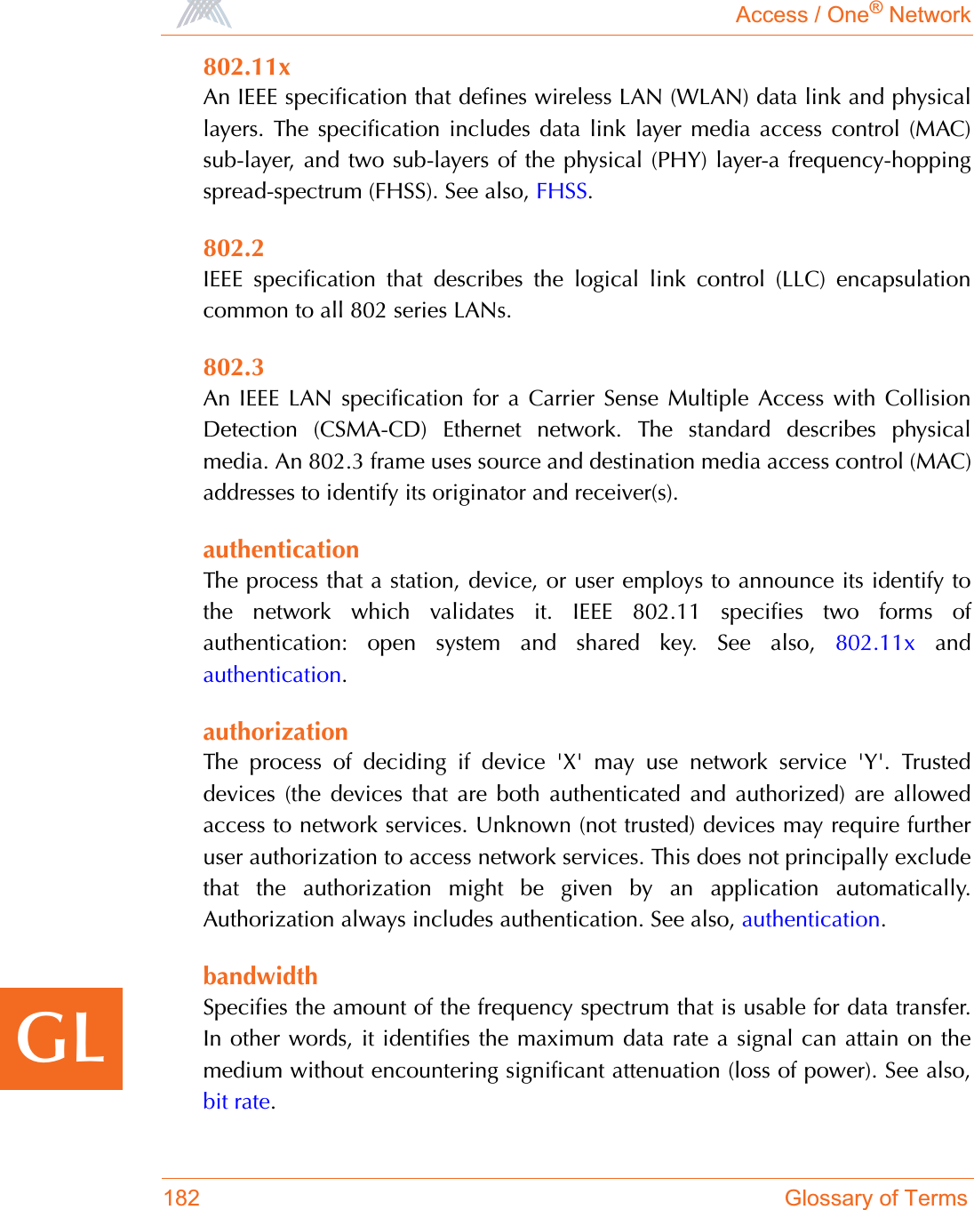
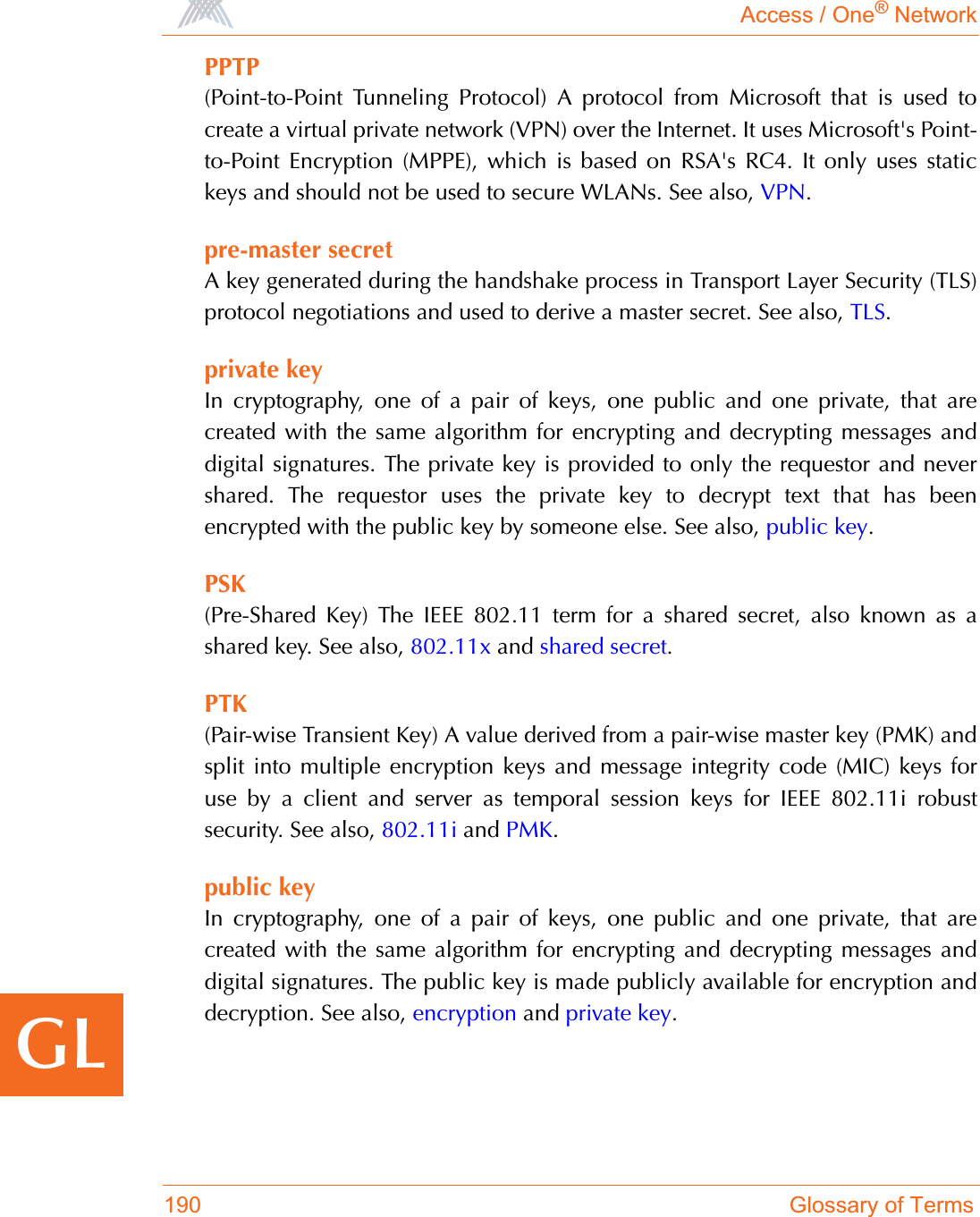
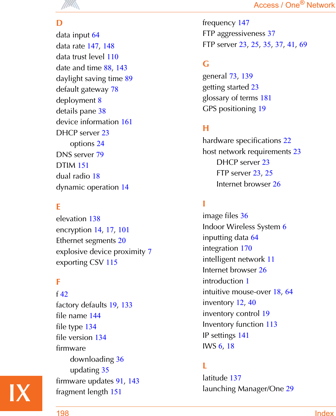
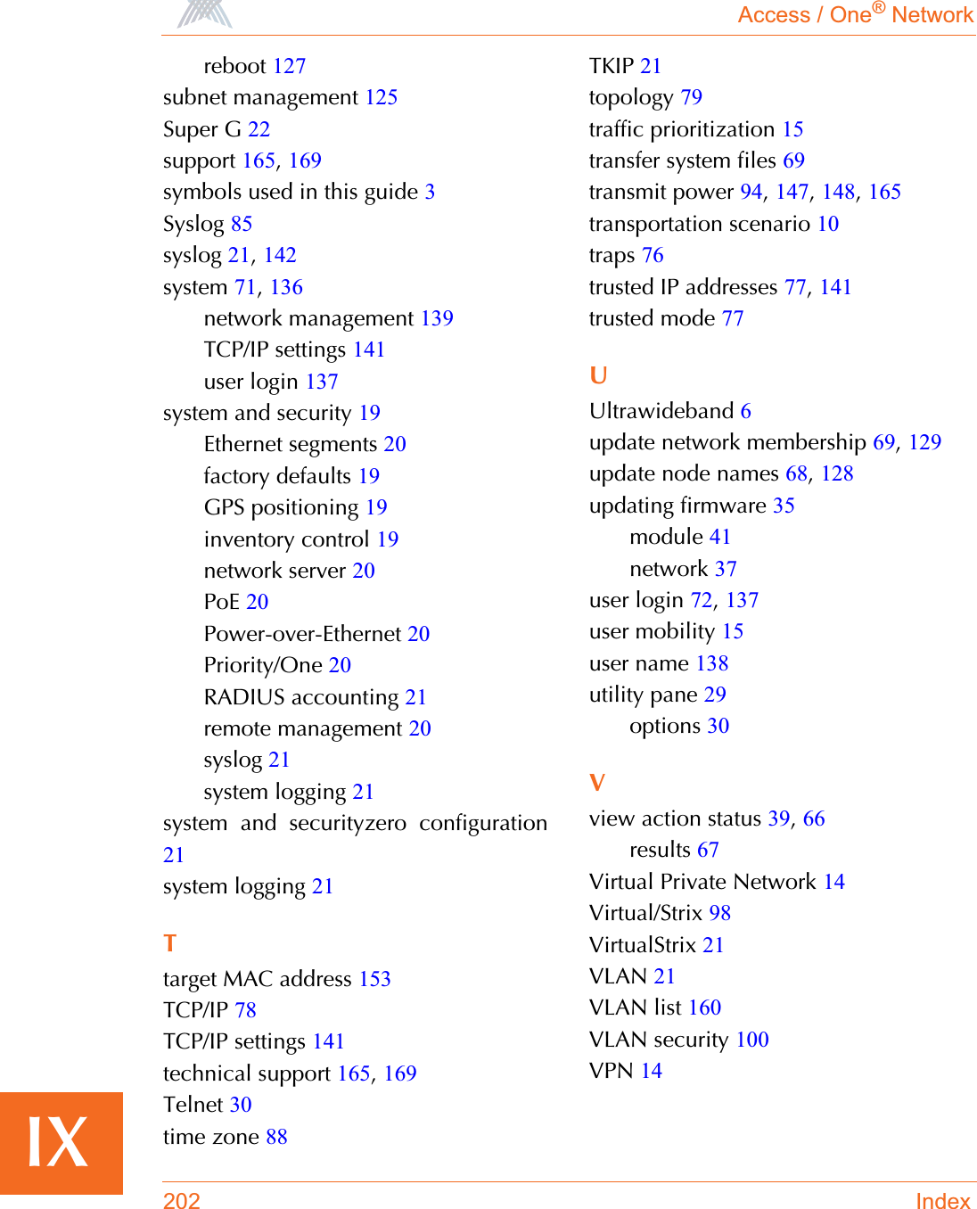
![Access / One® Network173BWireless SubsystemWARNING CLI login failed, invalid password.WARNING Too many invalid login attempts.NOTICE Telnet user logged in, user:XXXXX.NOTICE CLI user logged in, user:XXXXX.NOTICE Telnet user logged out, user:XXXXX.NOTICE CLI user logged out, user:XXXXX.NOTICE Super user logged in.Severity Syslog MessageEMERGENCY Failed to start the radio.EMERGENCY AP/STA features not enabled.EMERGENCY Error while starting the module. Wireless services disabled.EMERGENCY Radio interference detected on selected channel.WARNING Backhaul key mismatch. Putting it in RESTRICTED mode,mac:xx.xx.xx.xx.xx.xx.ALERT Radius authentication failed, mac:xx.xx.xx.xx.xx.xx.ERROR Association fails, can't find station in table, ssid:XXXXX,vlan:[id=x tag=x], mac:xx.xx.xx.xx.xx.x.ERROR Reassociation fails, can't find station in table, ssid:XXXXX, vlan:[id=x tag=x], mac:xx.xx.xx.xx.xx.x.ERROR Association fails, not authenticated, ssid:XXXXX,vlan:[id=x tag=x], mac:xx.xx.xx.xx.xx.xx.Severity Syslog Message](https://usermanual.wiki/Strix-Systems/ACCESS-ONE-32.Users-Manual-Part-IV/User-Guide-744246-Page-61.png)
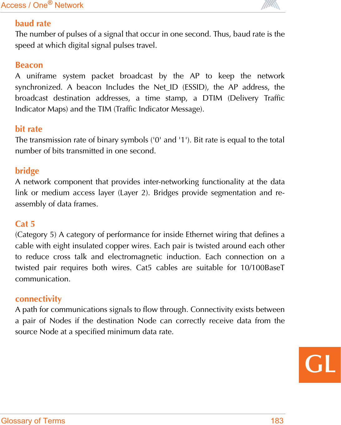
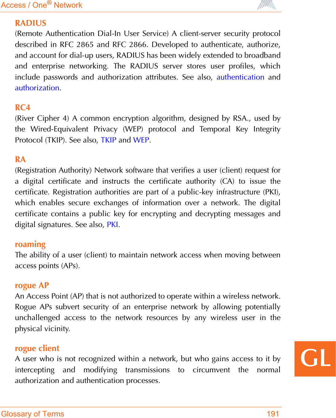
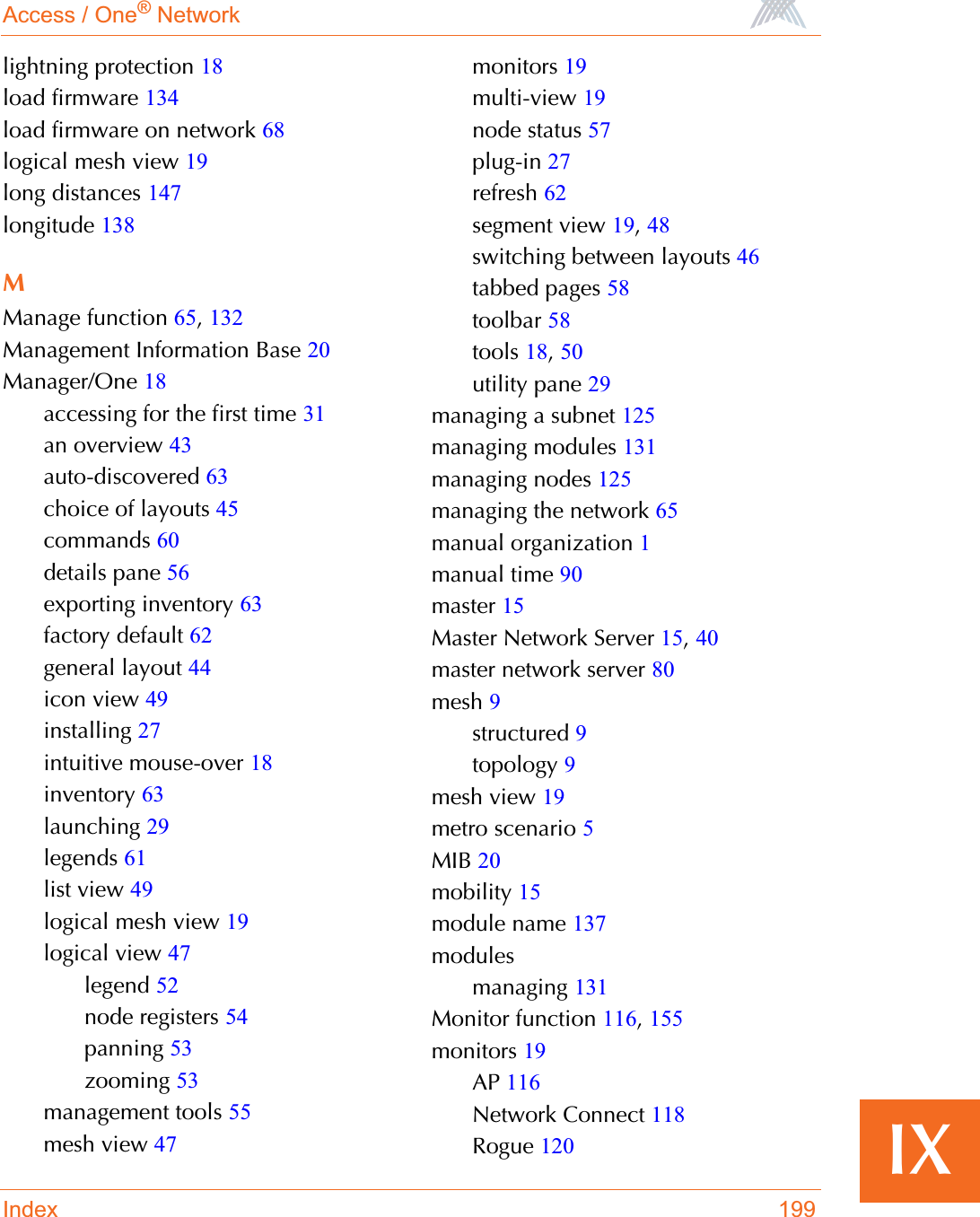
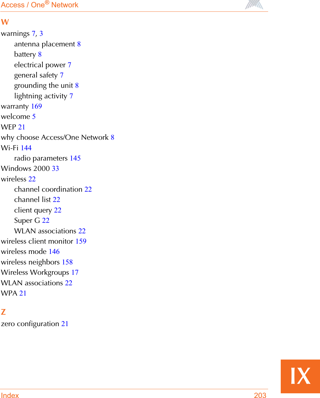
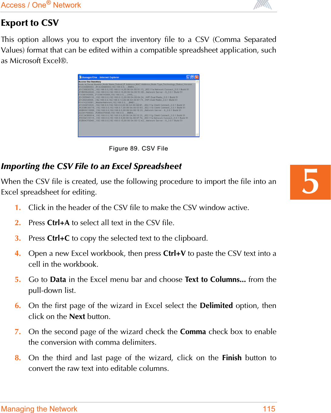
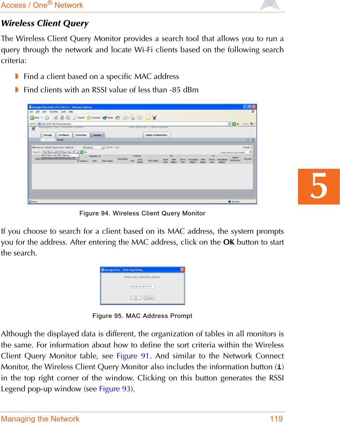
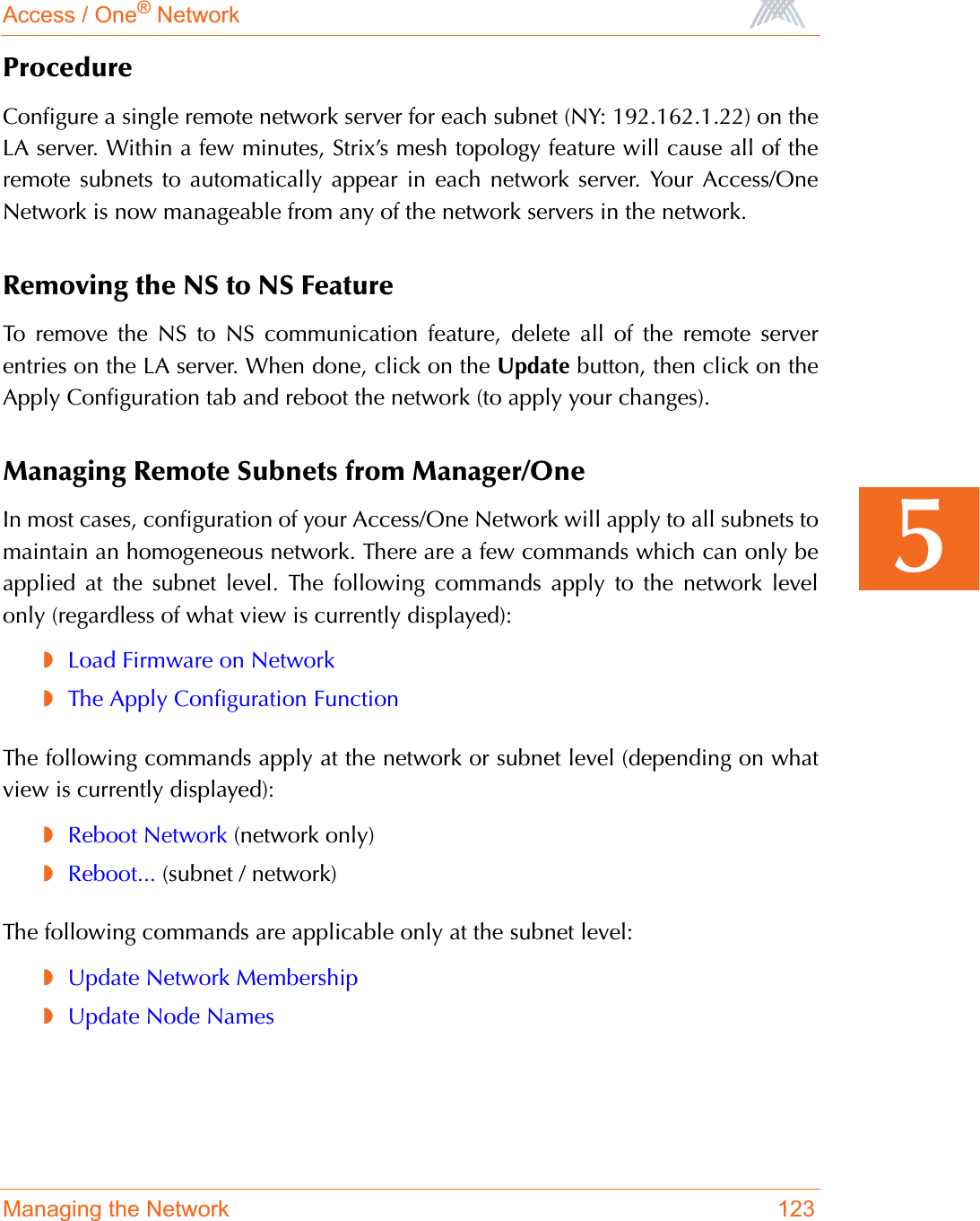
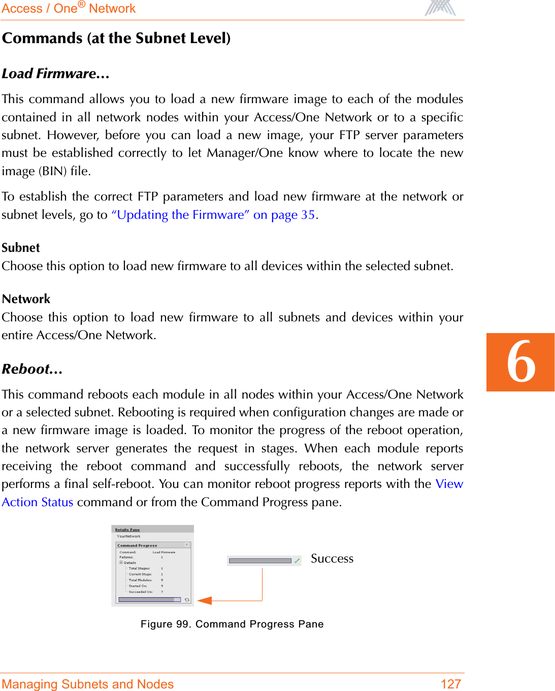
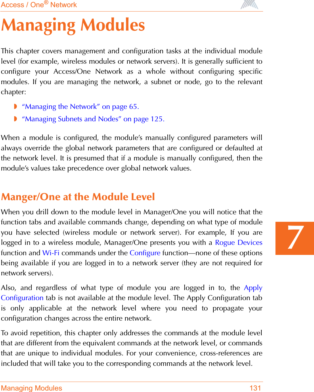
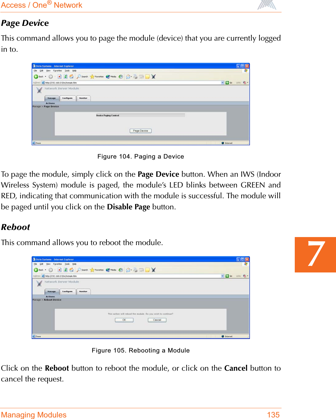
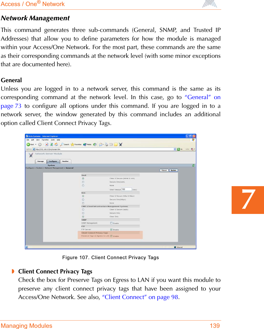
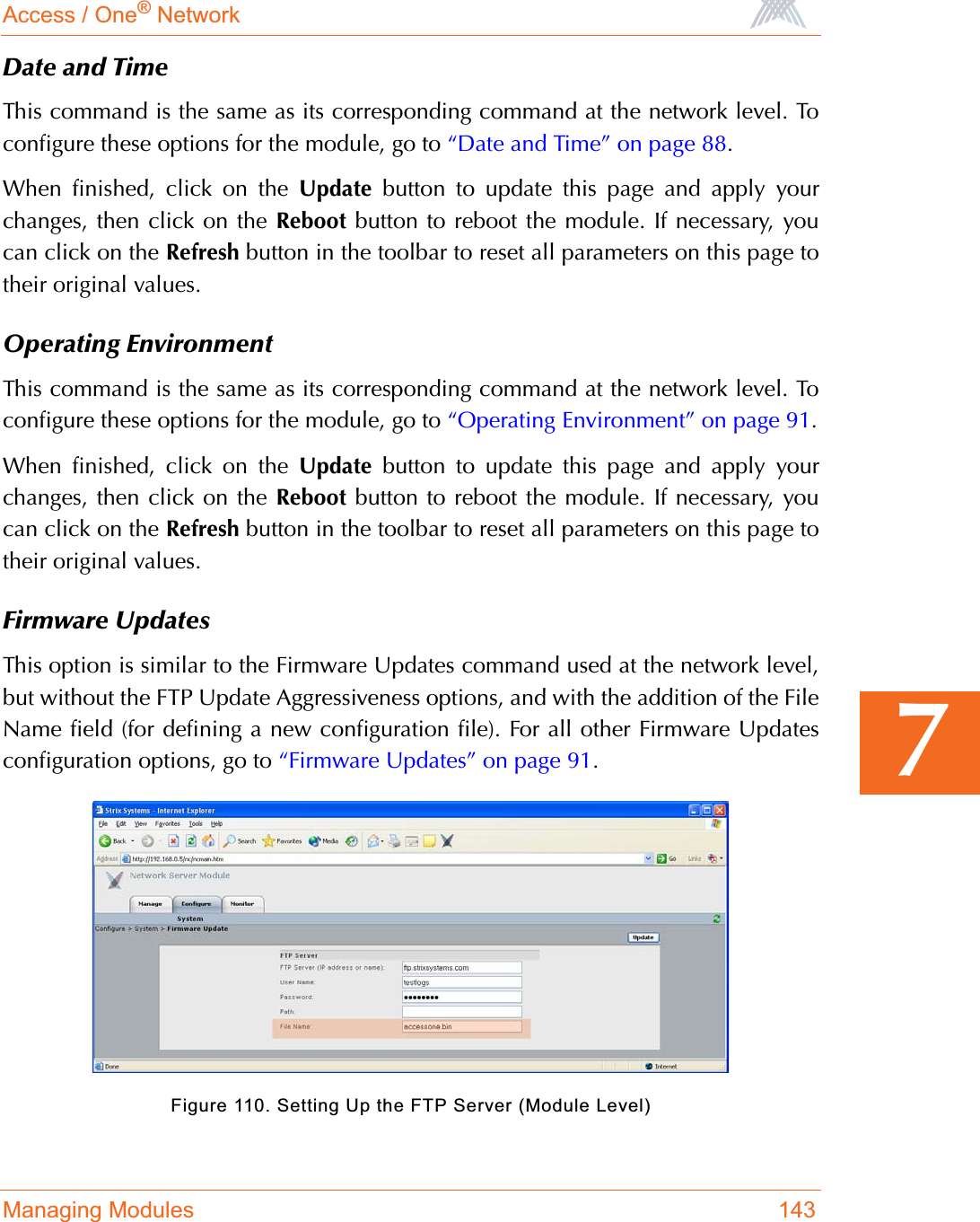
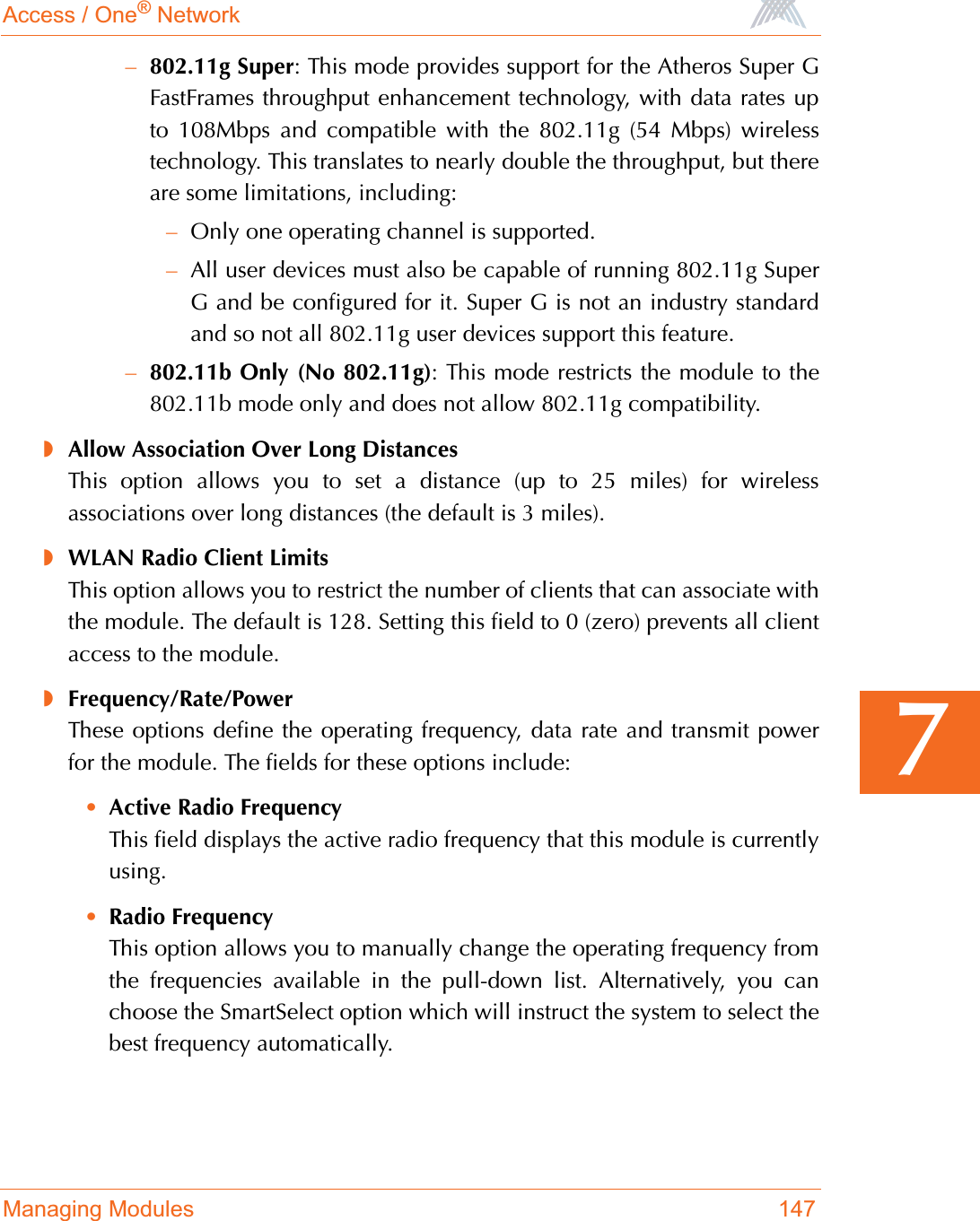
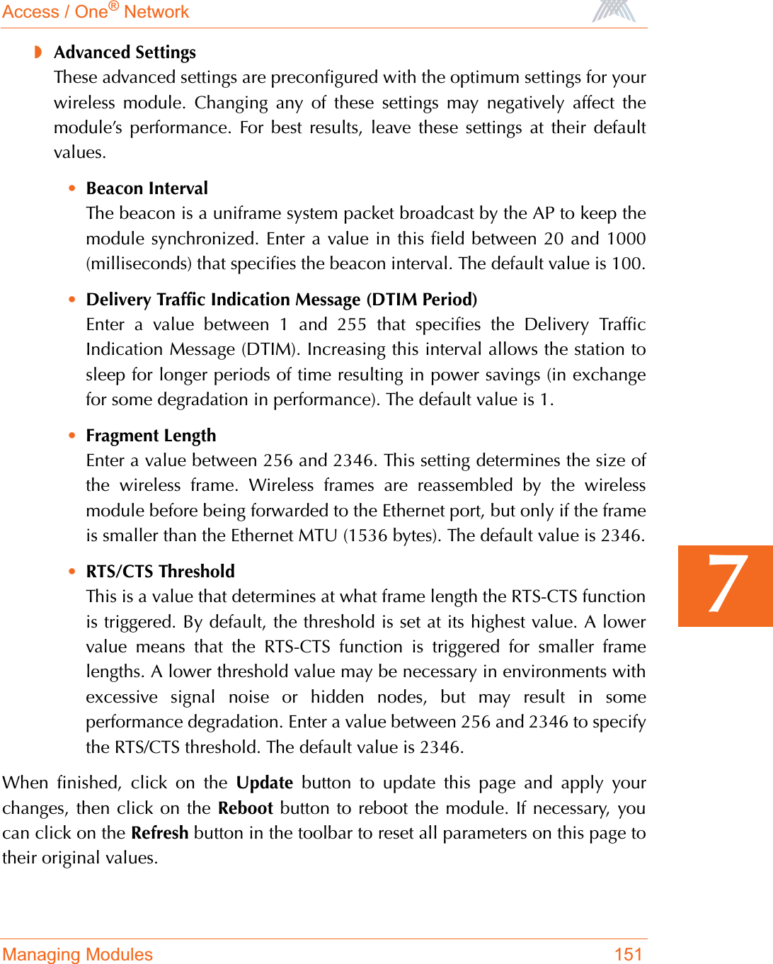
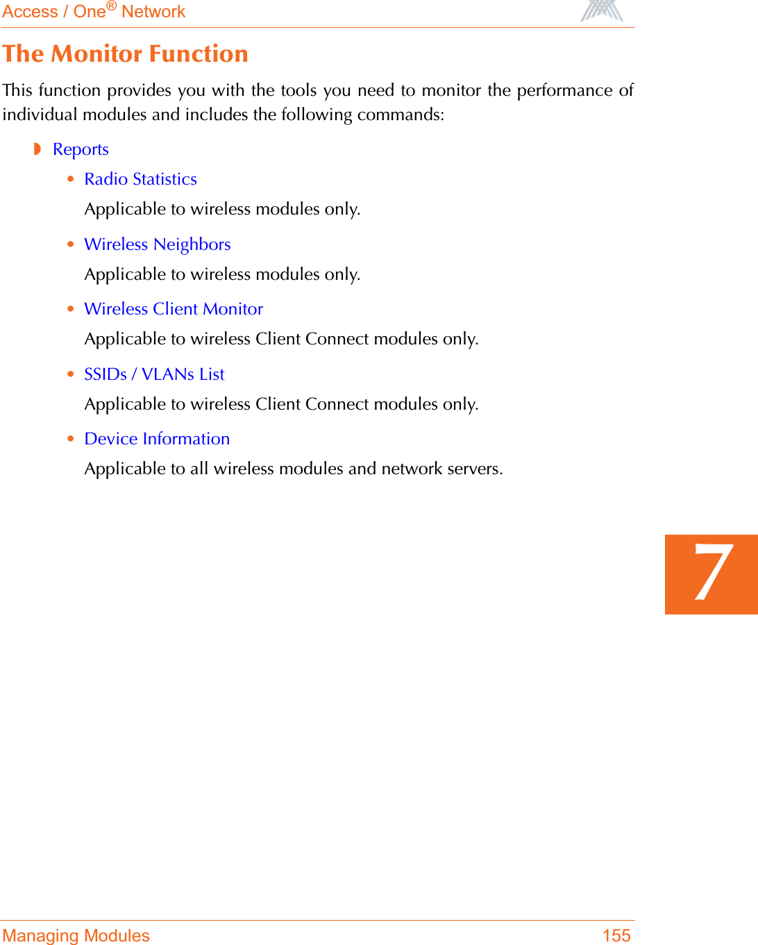
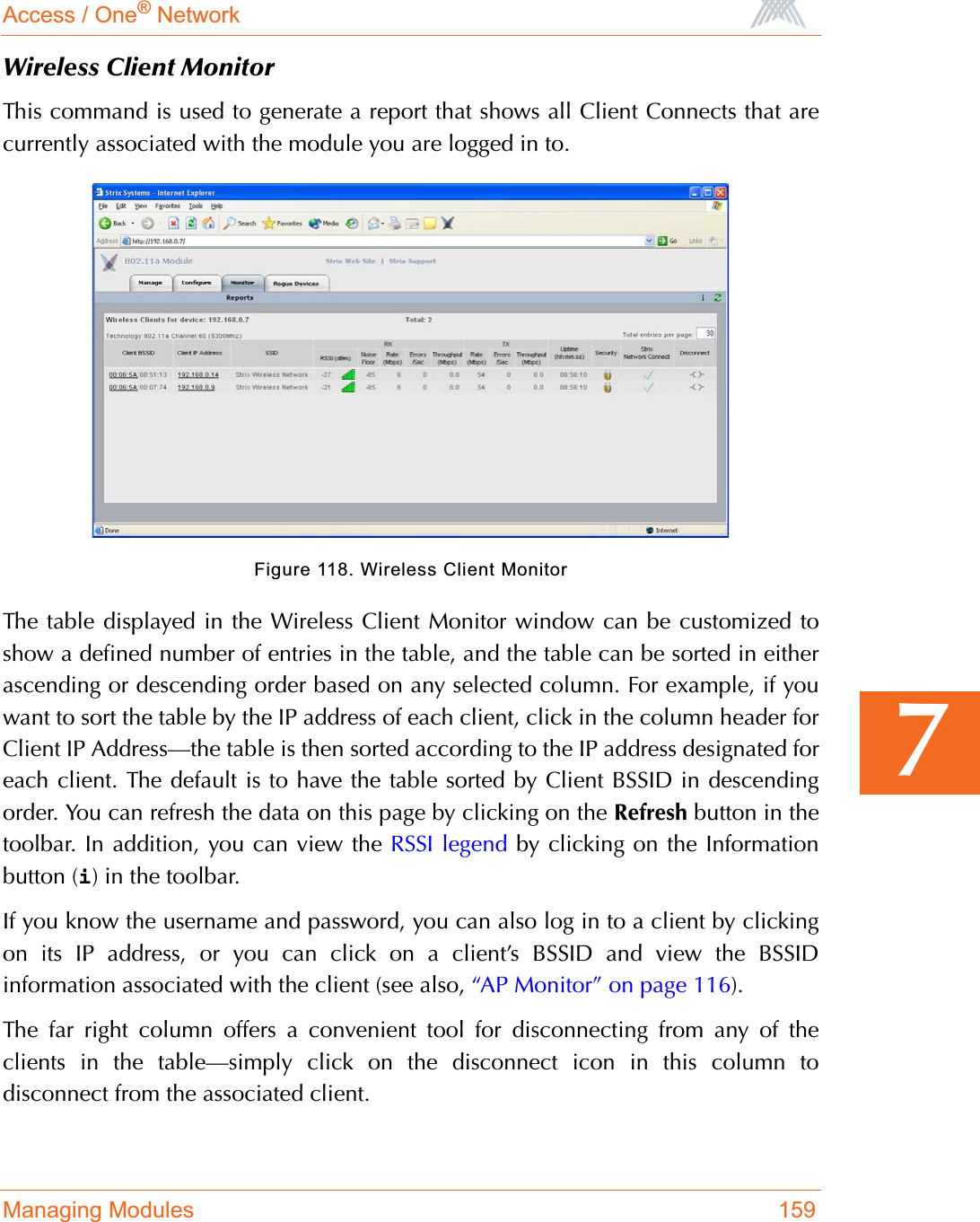
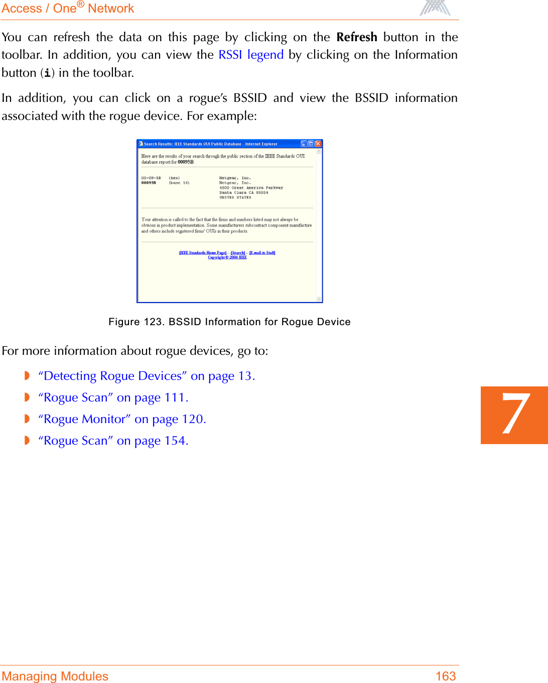
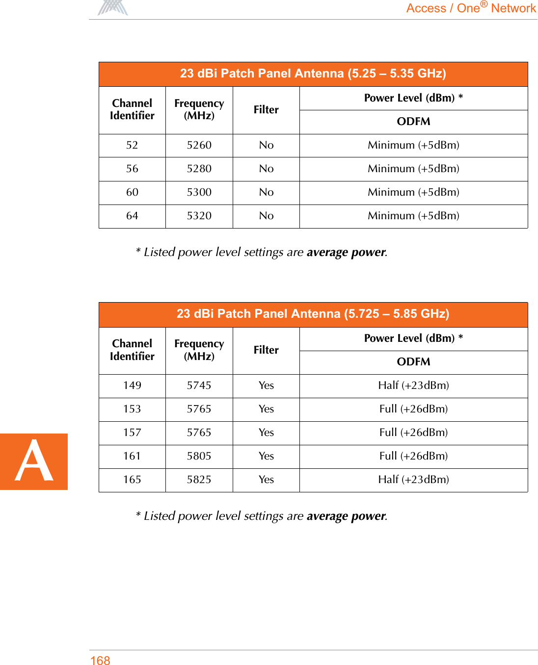
![Access / One® Network174BERROR Reassociation fails, not authenticated, ssid:XXXXX,vlan:[id=x tag=x], mac:xx.xx.xx.xx.xx.xx.ERROR Association fails, already associated, ssid:XXXXX,vlan:[id=x tag=x], mac:xx.xx.xx.xx.xx.xx.ERROR Reassociation fails, already associated, ssid:XXXXX,vlan:[id=x tag=x], mac:xx.xx.xx.xx.xx.xx.ERROR Association fails, can't authenticate during scan, ssid:ssid:XXXXX, vlan:[id=x tag=x], mac:xx.xx.xx.xx.xx.xx.ERROR Reassociation fails, can't authenticate during scan, ssid:ssid:XXXXX, vlan:[id=x tag=x], mac:xx.xx.xx.xx.xx.xx.ERROR Association fails, reason:xxxx, wlanmode:xxxx, ssid:XXXXXX, vlan:[Id=x Tag=x],mac:xx:xx:xx:xx:xx:xx.ERROR Reassociation fails, reason:xxxx, wlanmode:xxxx, ssid:XXXXXX, vlan:[Id=x Tag=x],mac:xx:xx:xx:xx:xx:xx.ERROR Bad authentication transaction sequence, number:XX, type=XXXXX, mac:xx.xx.xx.xx.xx.xx.ERROR Authentication[1] fails, can't find station in table, mac:xx.xx.xx.xx.xx.xx.ERROR Authentication[1] fails, can't authenticate in scan mode, mac:xx.xx.xx.xx.xx.xx.ERROR Authentication[3] fails, can't find station in table, mac:xx.xx.xx.xx.xx.xx.ERROR Authentication[3] done, error in Tx, wlanmode:X, mac:xx.xx.xx.xx.xx.xx.ERROR Deauthentication requested, can't find station in table, mac:xx.xx.xx.xx.xx.xx.Severity Syslog Message](https://usermanual.wiki/Strix-Systems/ACCESS-ONE-32.Users-Manual-Part-IV/User-Guide-744246-Page-62.png)
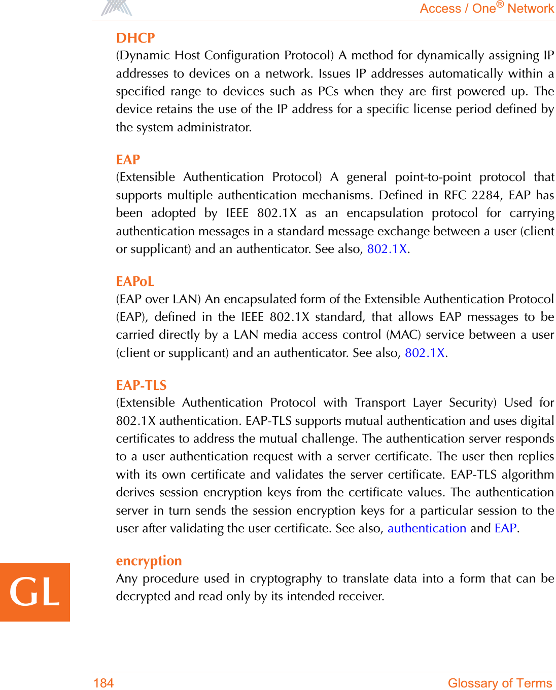
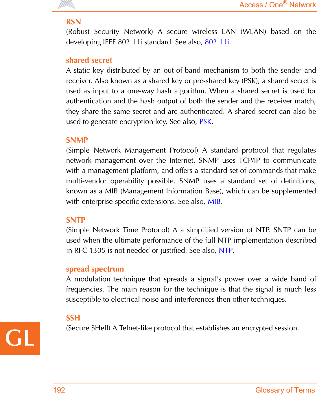
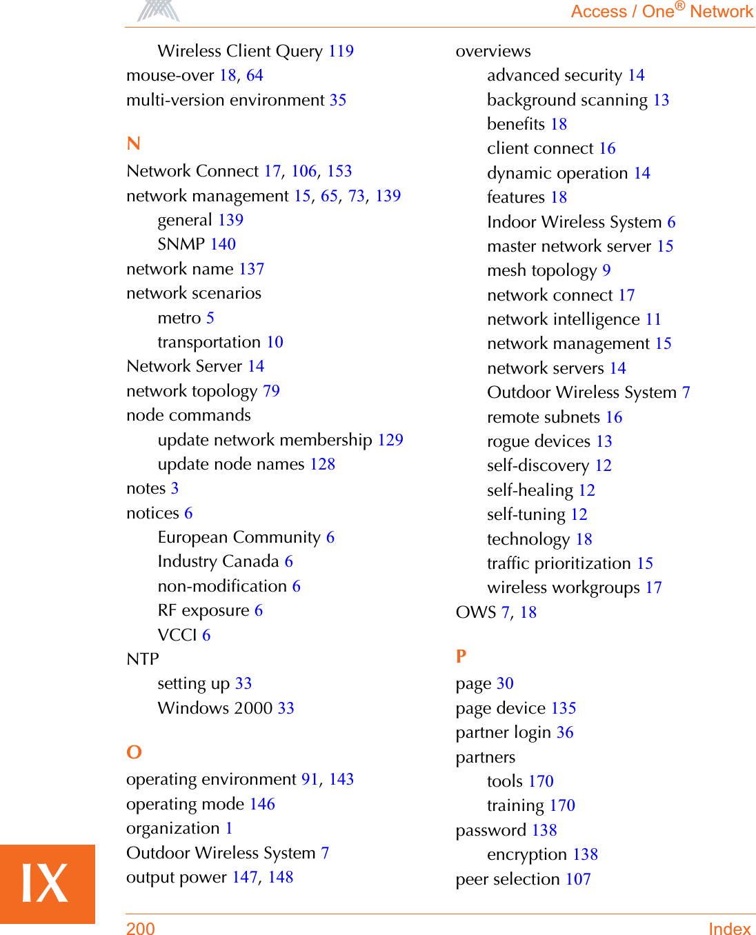
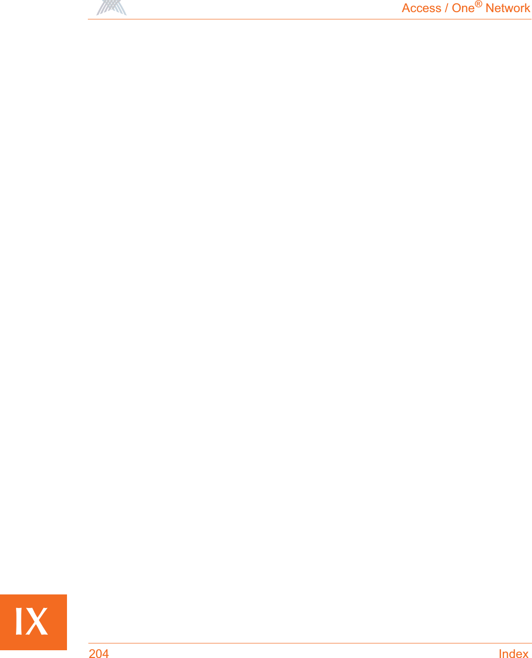
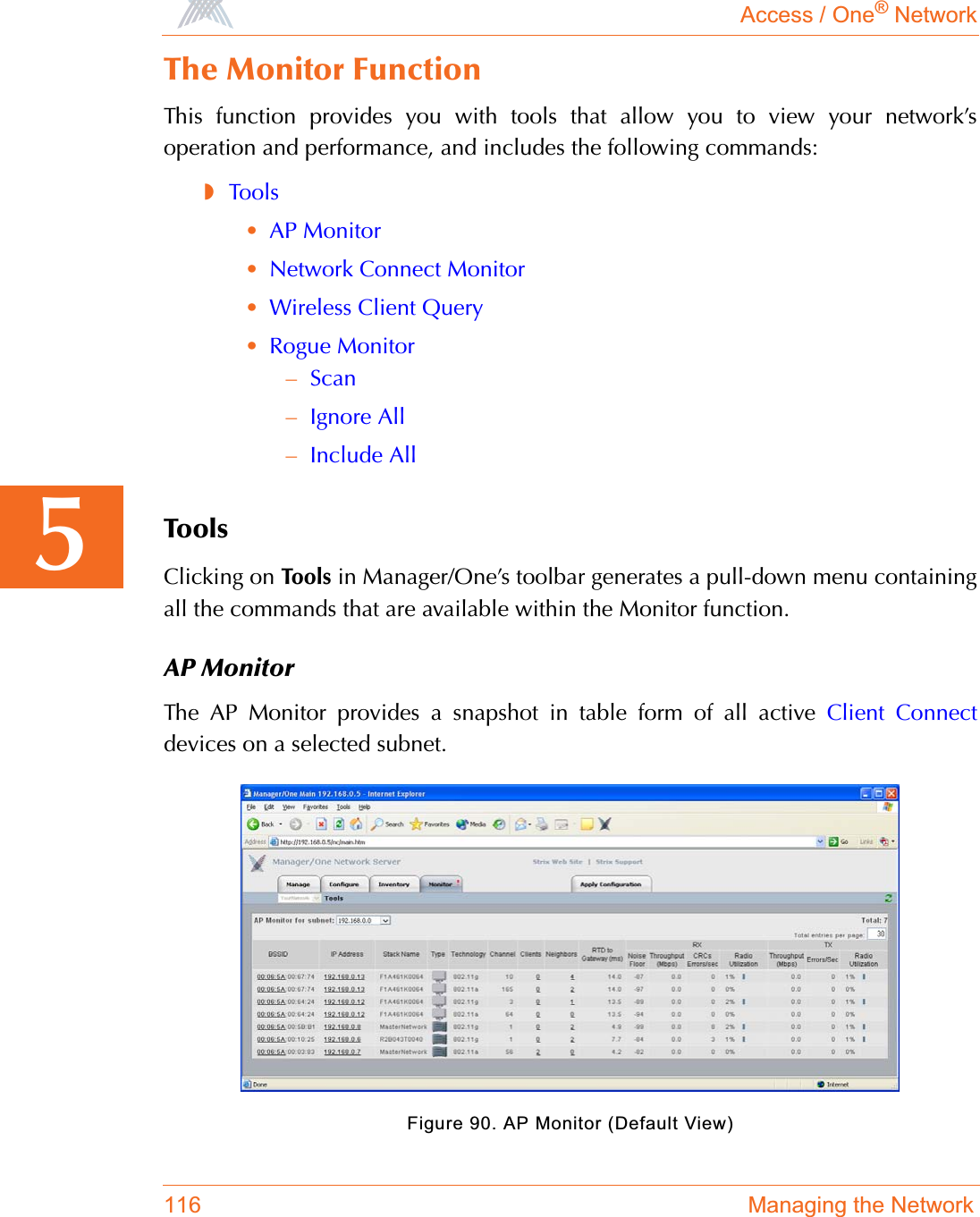
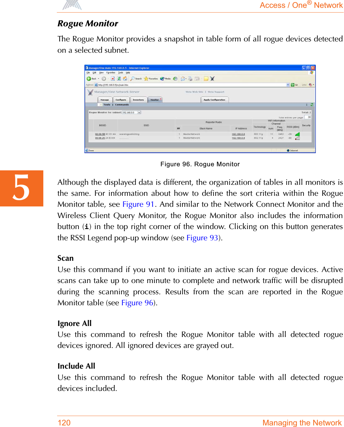
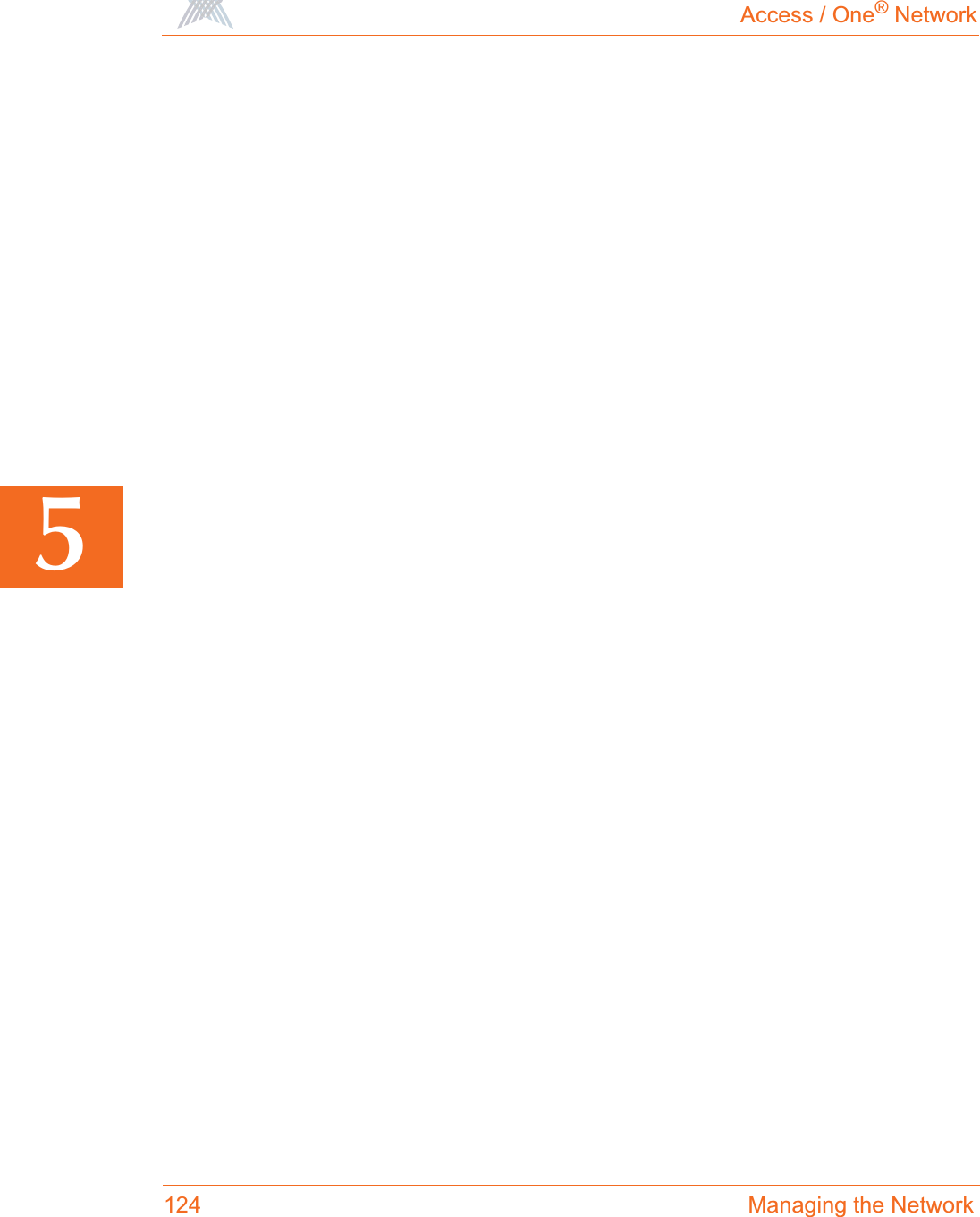
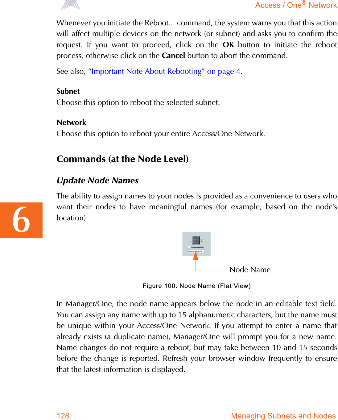
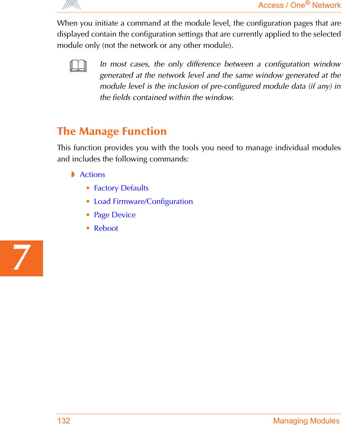
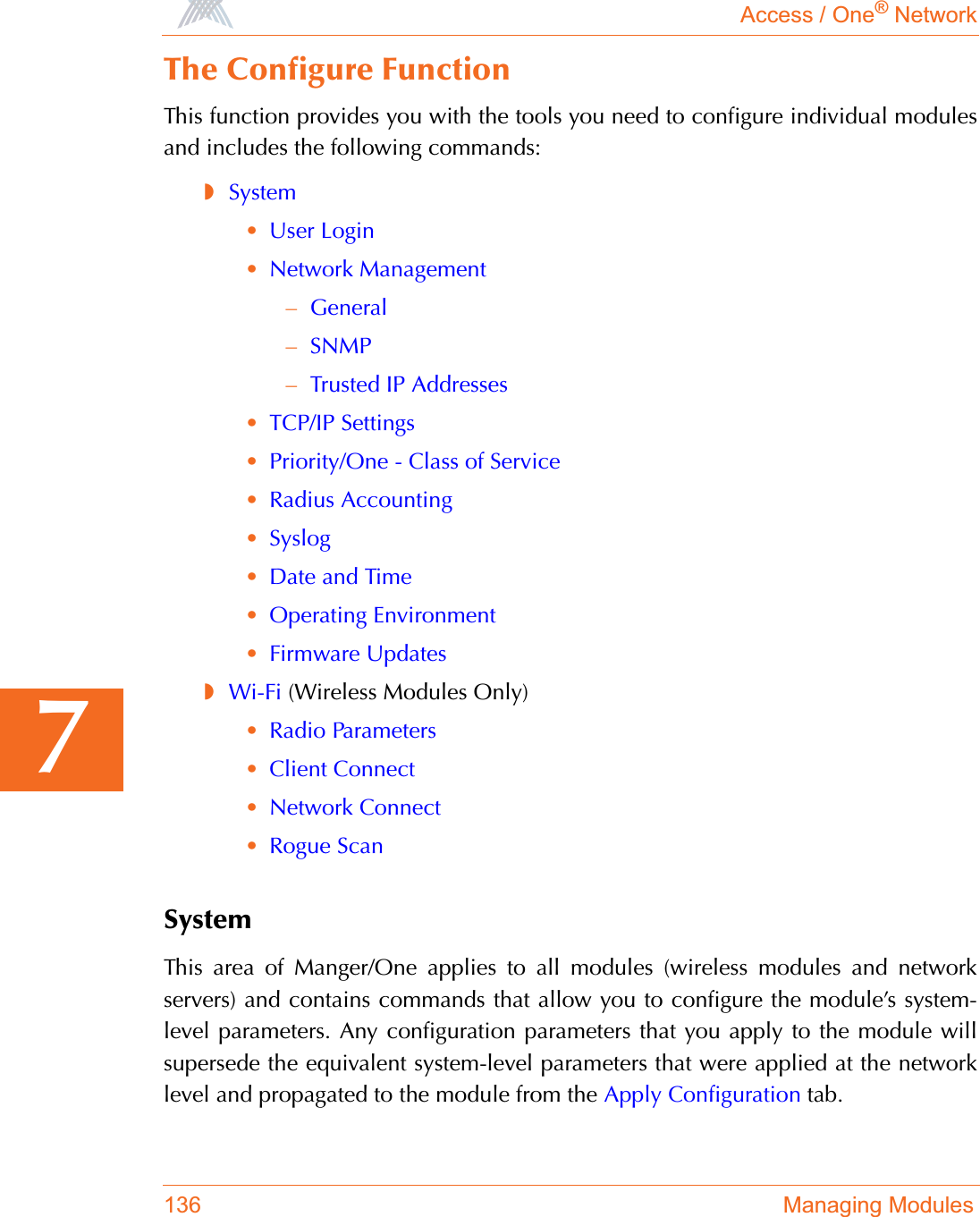
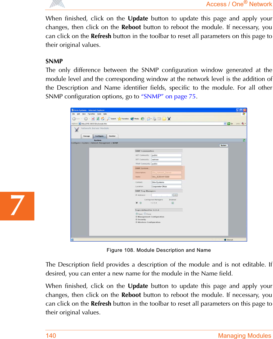
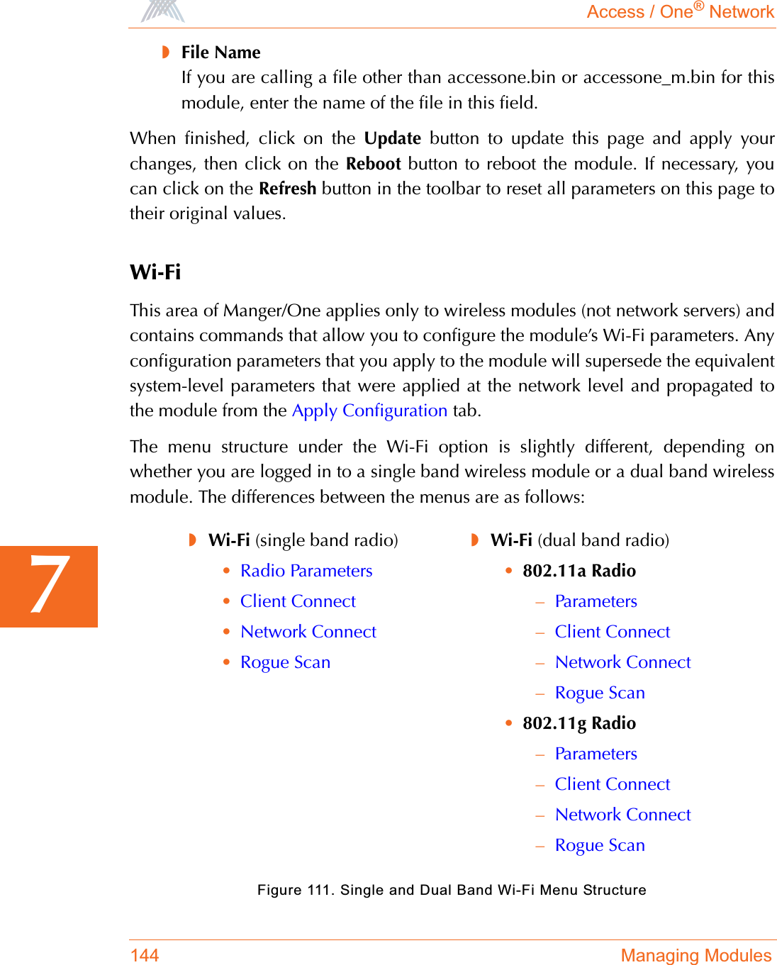
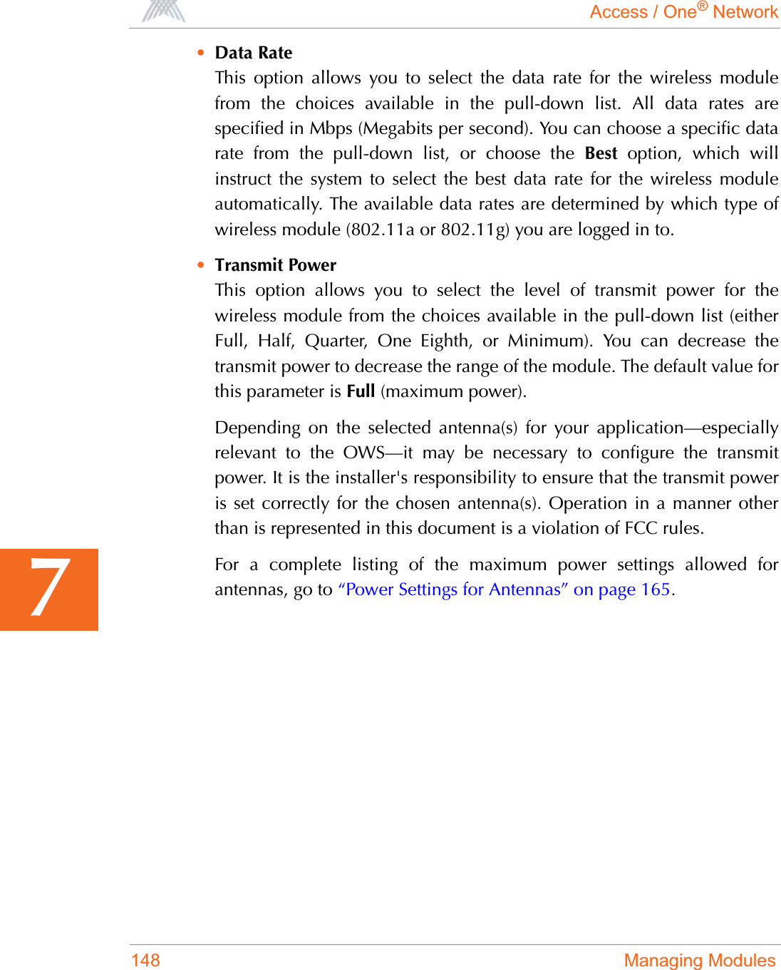
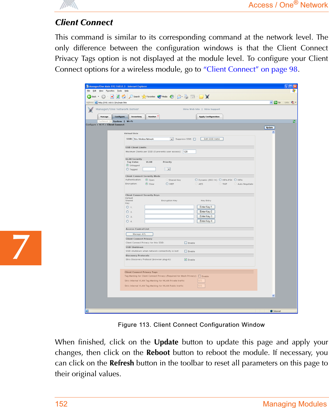
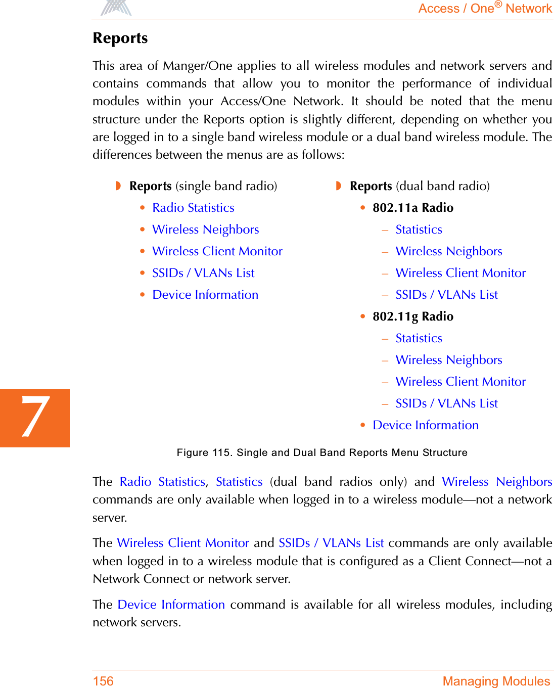
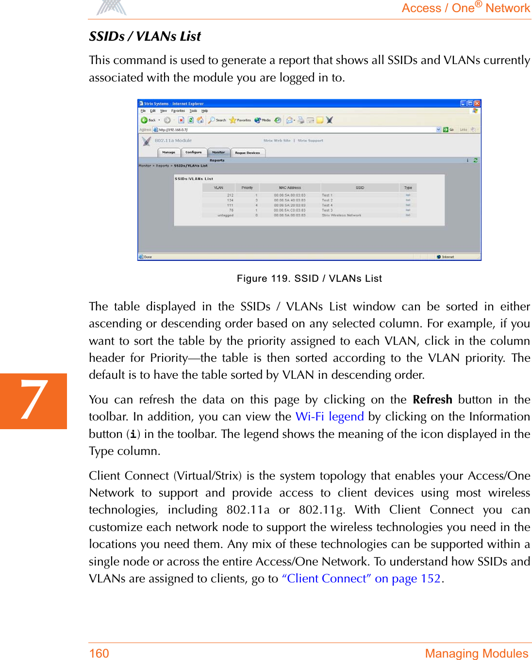
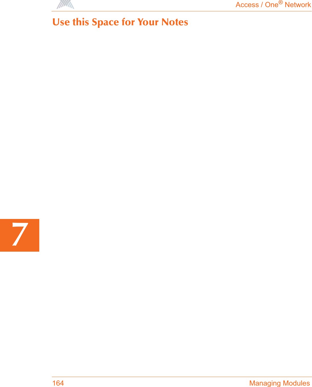
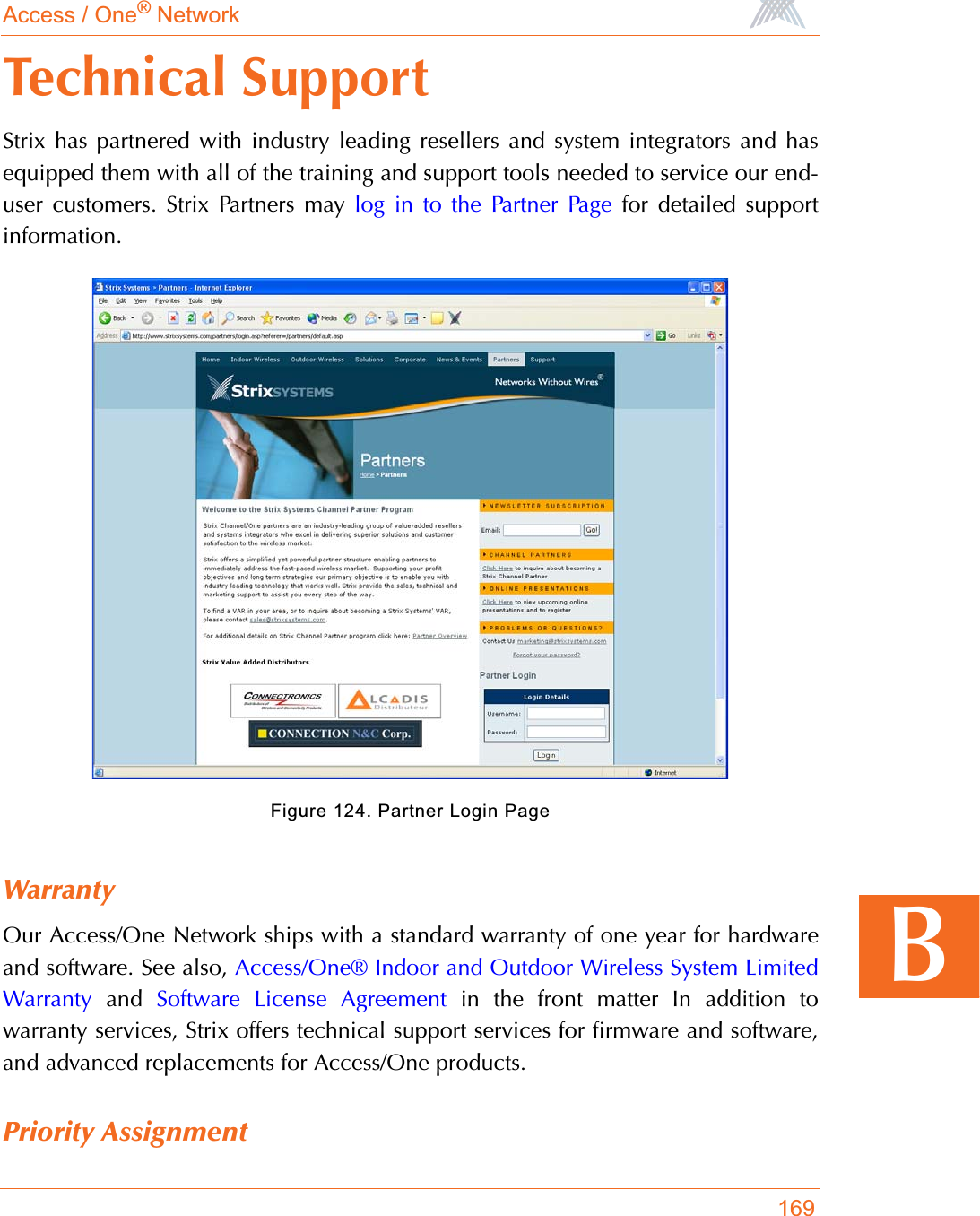
![Access / One® Network175BERROR Association fails, module is not ready, mac:xx:xx:xx:xx:xx:xx.ERROR Reassociation fails, module is not ready, mac:xx:xx:xx:xx:xx:xx.WARNING Authentication[3] fails, auth:shared, wlanmode:X, mac:xx.xx.xx.xx.xx.xx.WARNING Unsupported 802.11 authentication request, auth:LEAP, wlanmode:X, mac:xx.xx.xx.xx.xx.xx.WARNING Unsupported 802.11 authentication request, auth:x(hex), wlanmode:X, mac:xx.xx.xx.xx.xx.xx.WARNING Deauthentication fails, incorrect source, mac:xx.xx.xx.xx.xx.xx.WARNING Deauthentication fails, unknown source, mac:xx.xx.xx.xx.xx.xx.WARNING Association fails, wrong ssid, ssid:XXXXX, vlan:[id=x tag=x], mac:xx.xx.xx.xx.xx.xx.WARNING Reassociation fails, wrong ssid, ssid:XXXXX, vlan:[id=x tag=x], mac:xx.xx.xx.xx.xx.xx.WARNING NC-sel approves RESTRICTED Mode.WARNING Backhaul [mac:xx:xx:xx:xx:xx:xx] at if=XXXX is put to RESTRICTED mode.WARNING Loop is detected at if=XX. Mac:xx:xx:xx:xx:xx:xx.NOTICE NC-sel approves OPEN Mode.NOTICE Backhaul is using default cloud name. Putting it in RESTRICTED mode,mac:xx.xx.xx.xx.xx.xx.NOTICE AP has put backhaul in RESTRICTED mode.Severity Syslog Message](https://usermanual.wiki/Strix-Systems/ACCESS-ONE-32.Users-Manual-Part-IV/User-Guide-744246-Page-63.png)
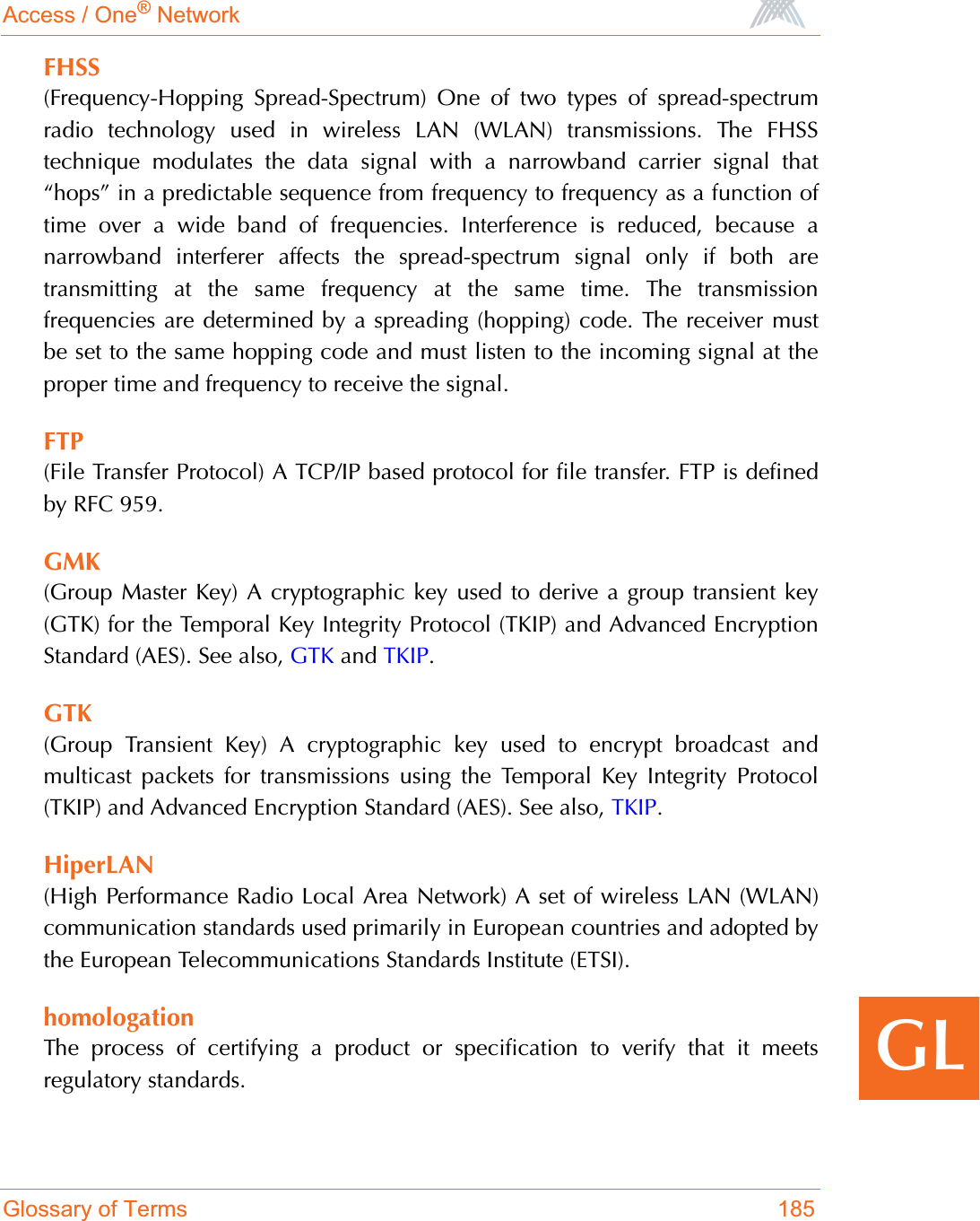
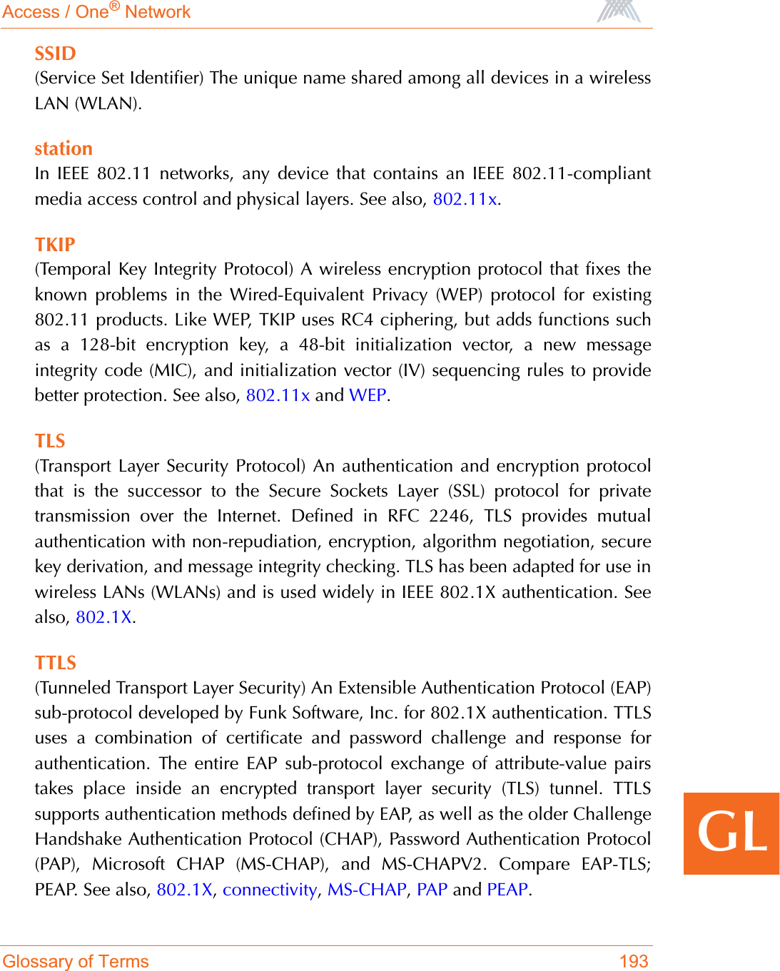
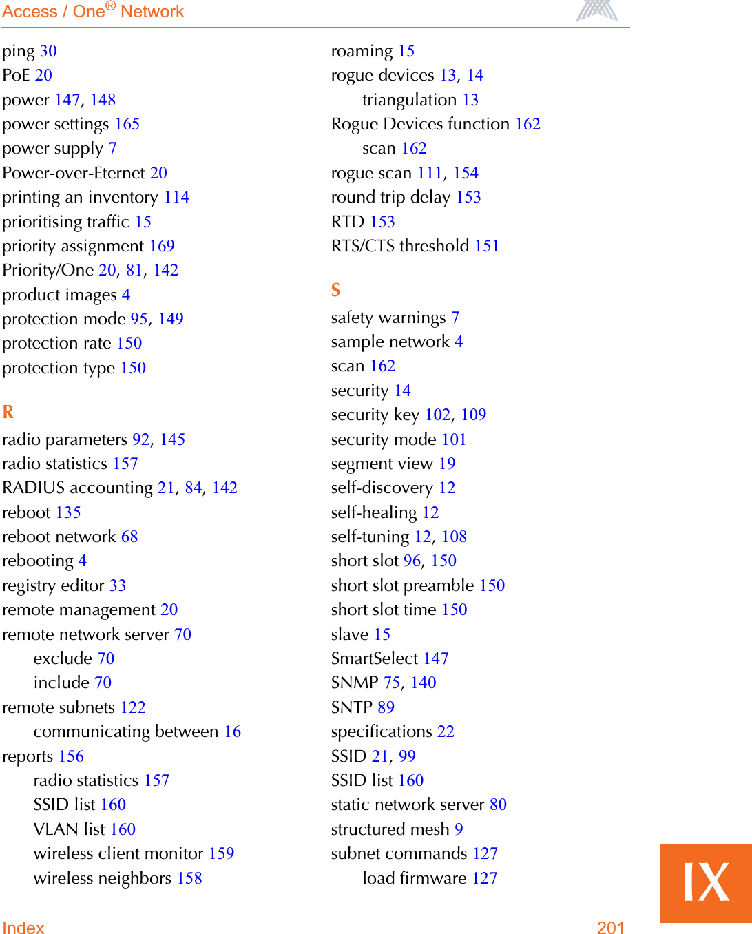
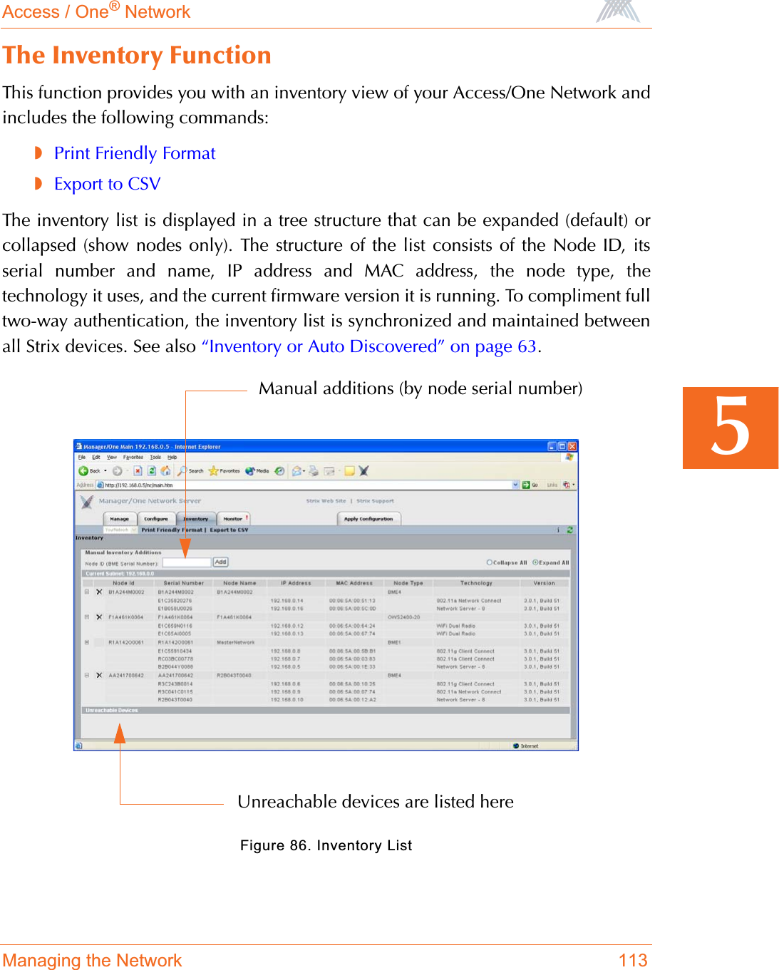
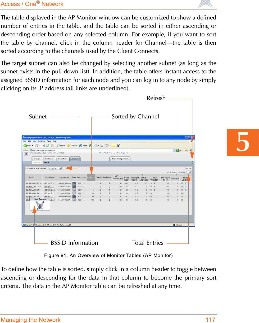
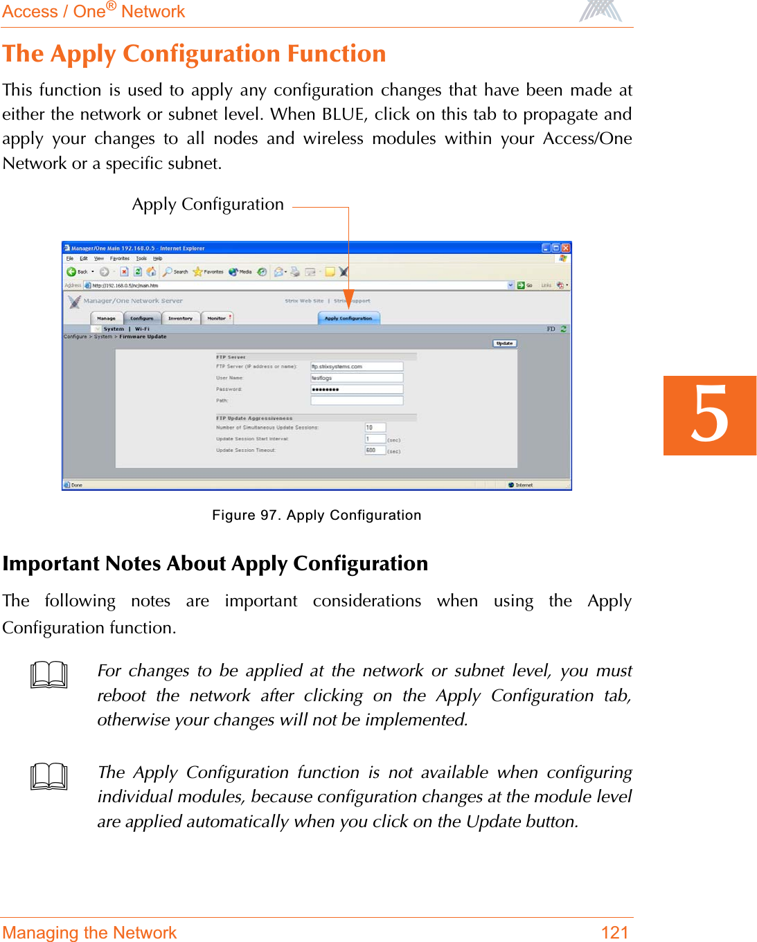
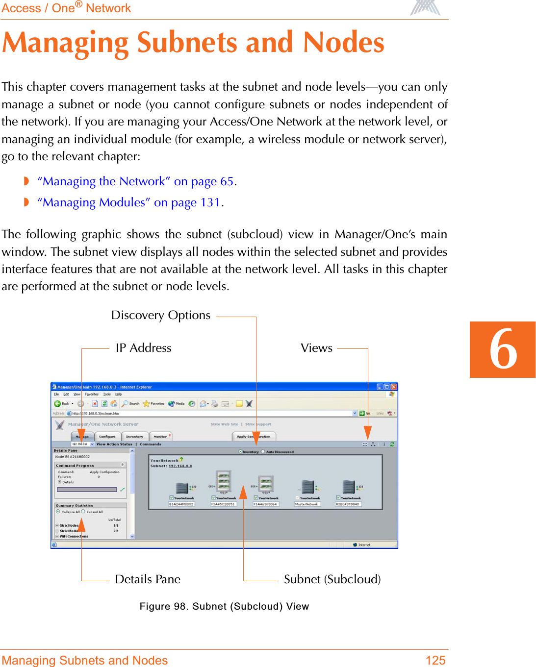
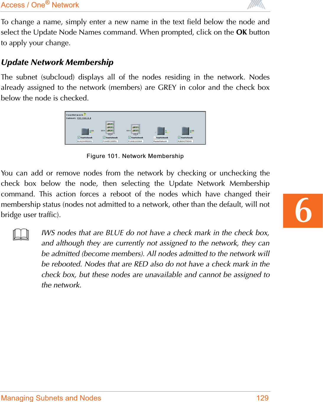
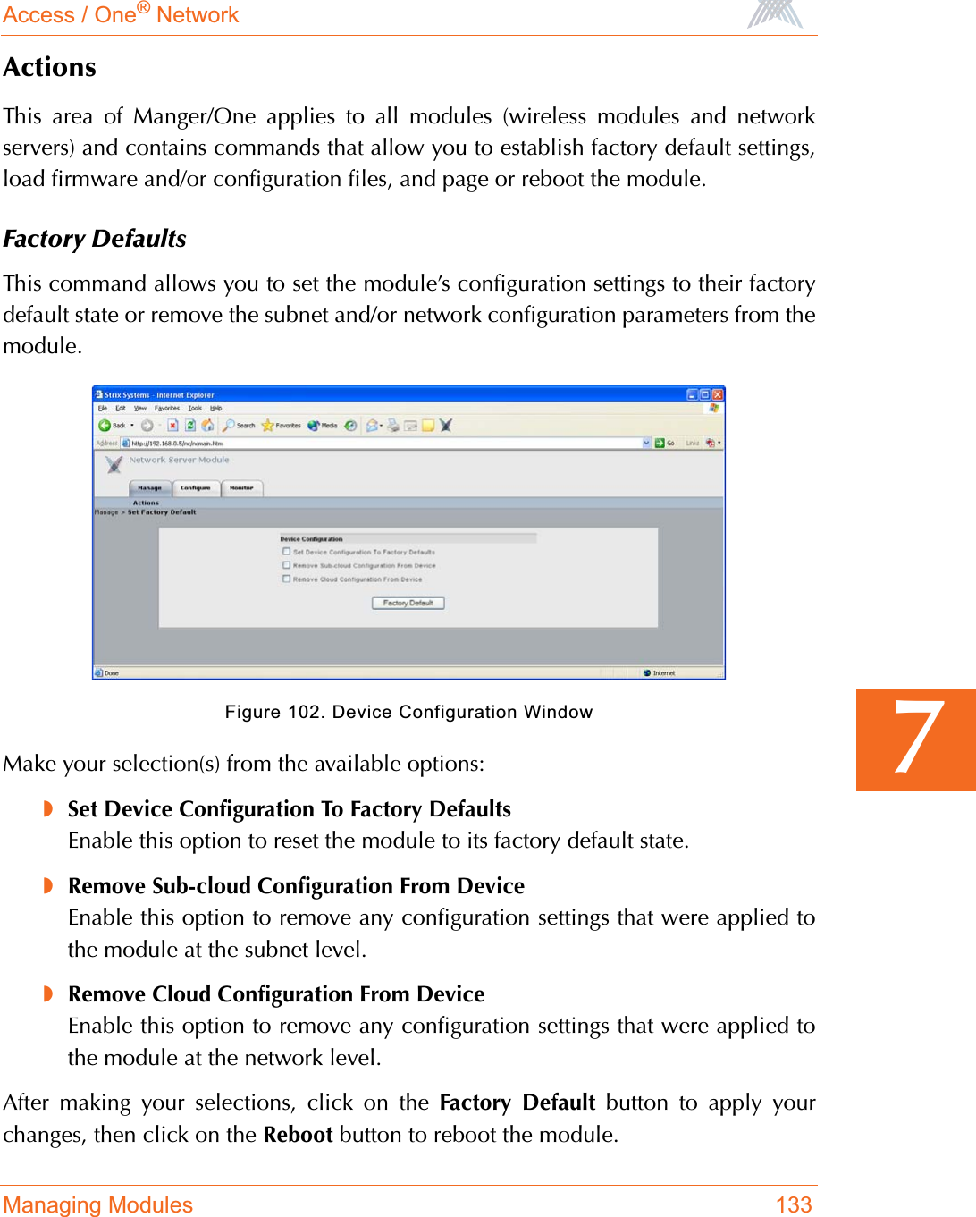
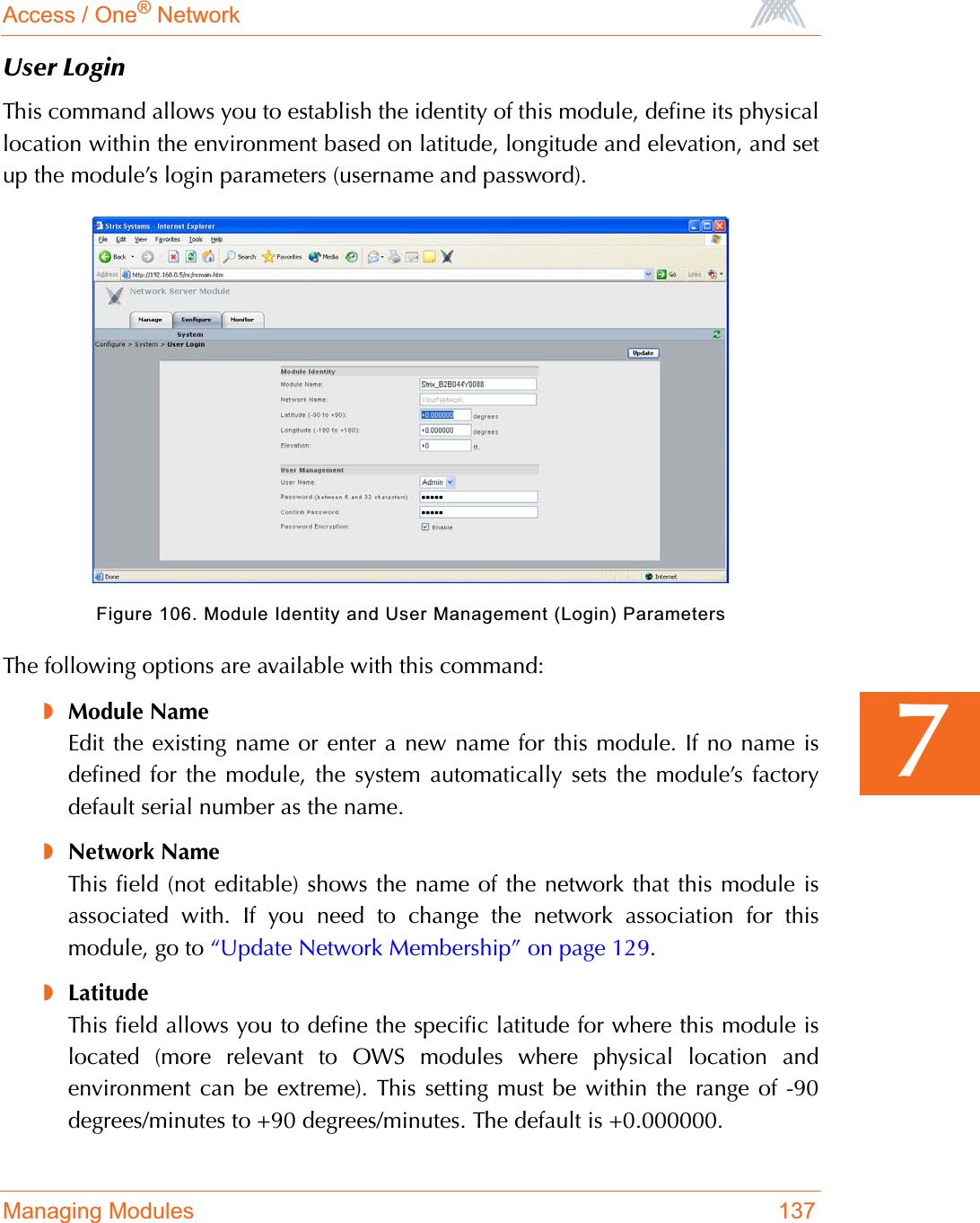
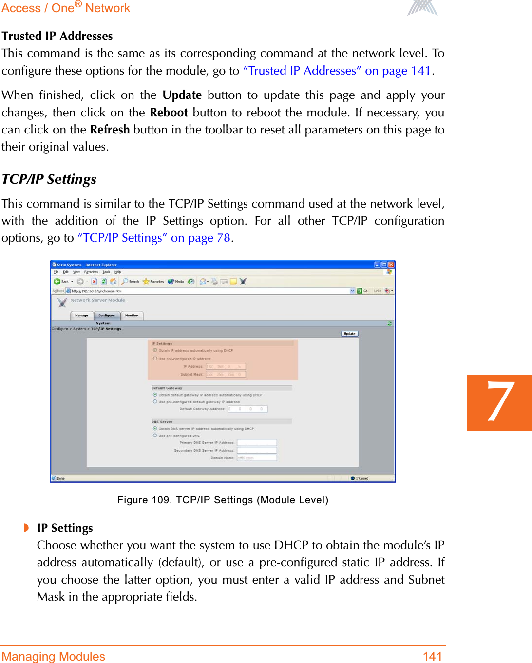
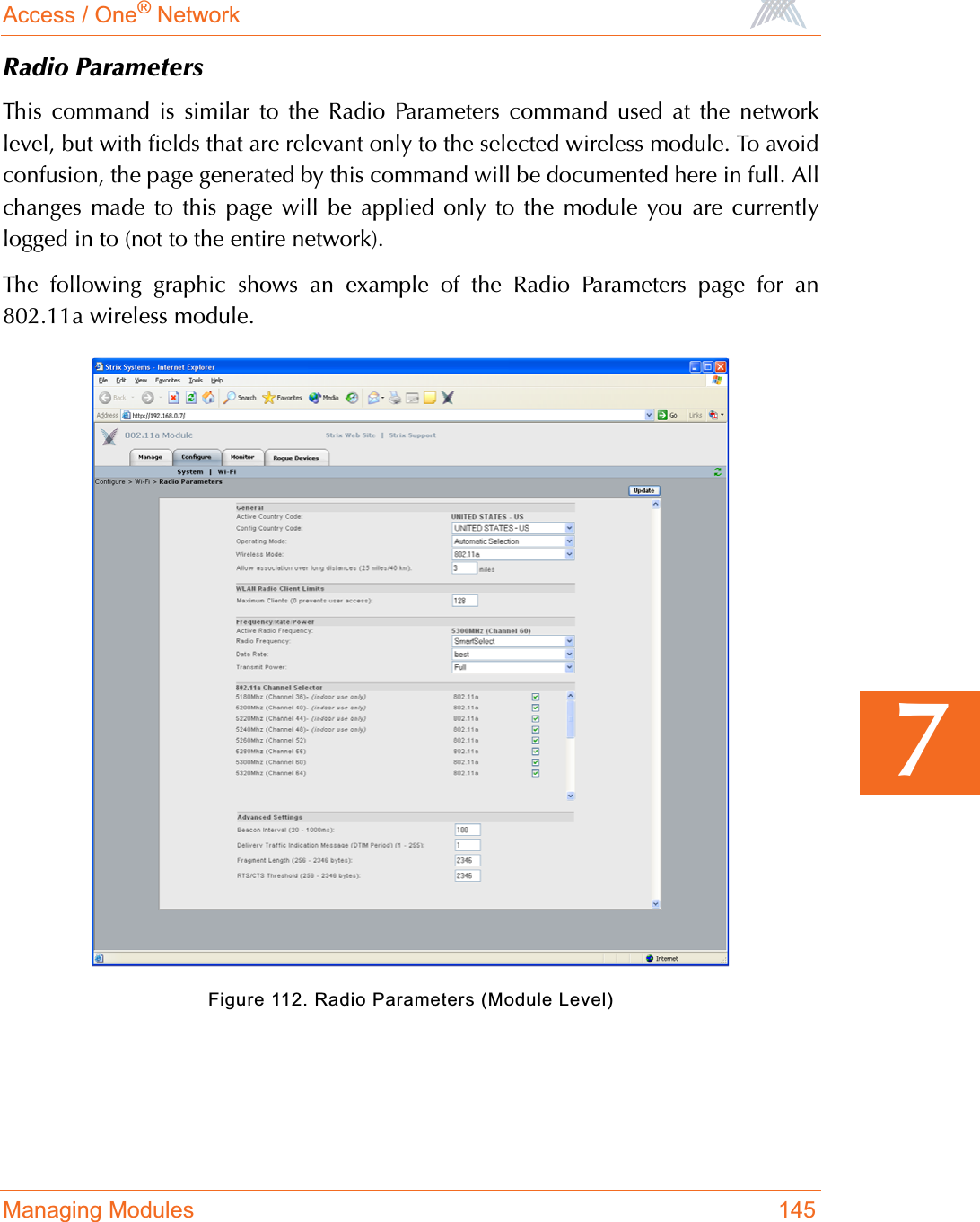
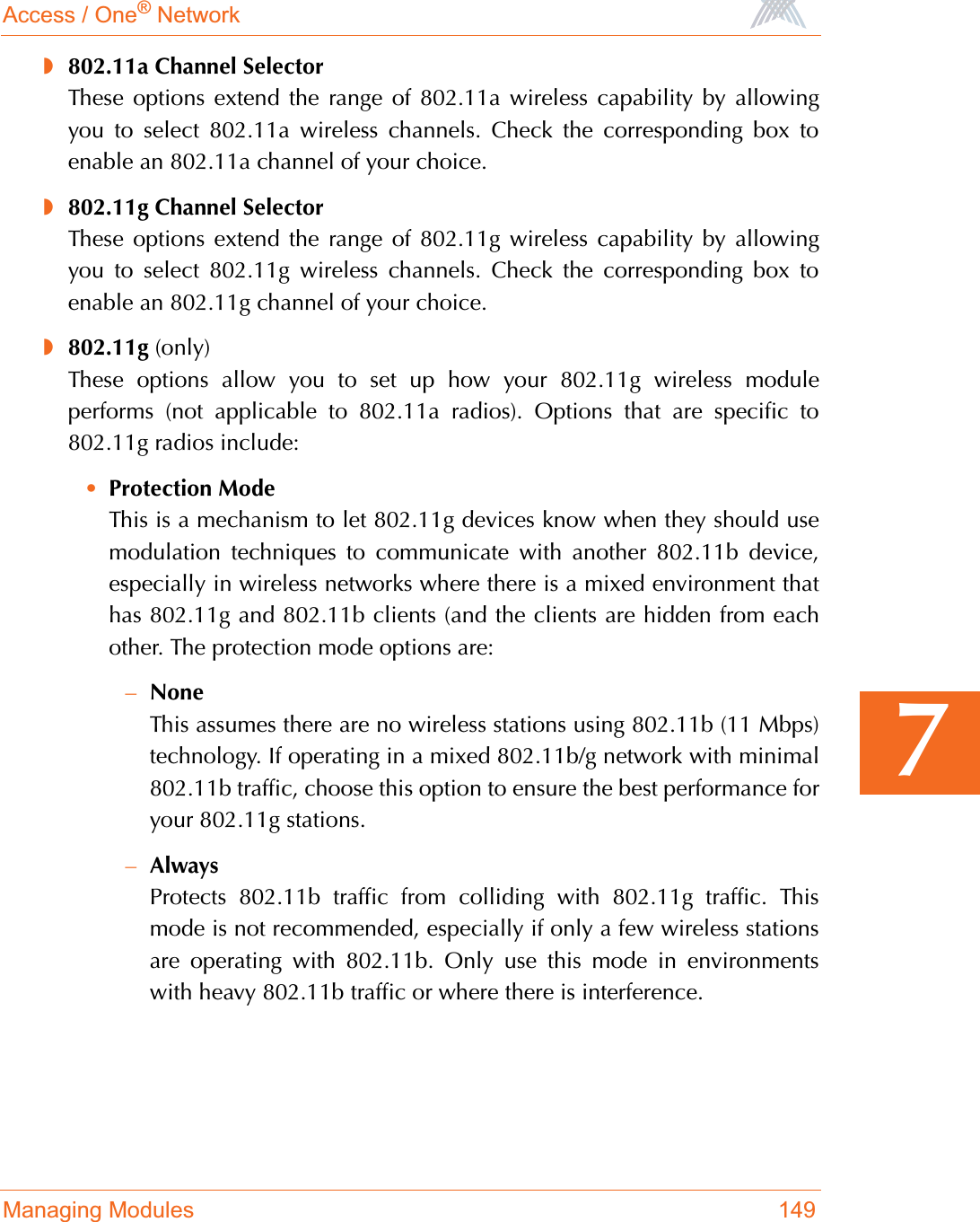
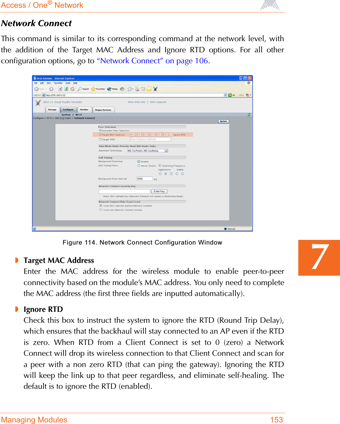
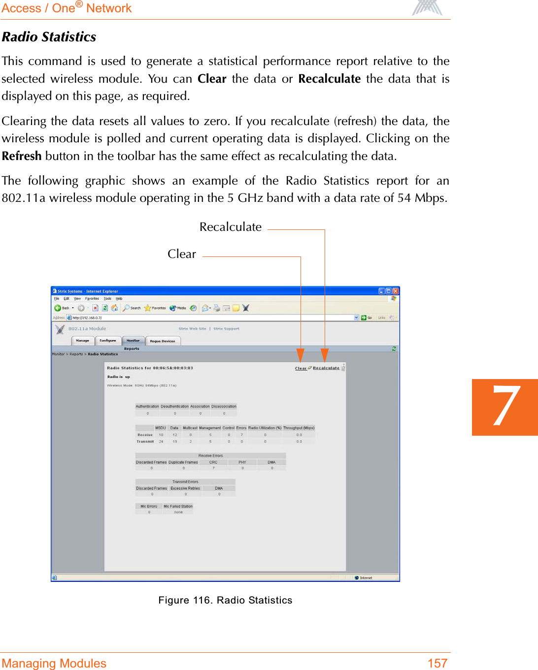
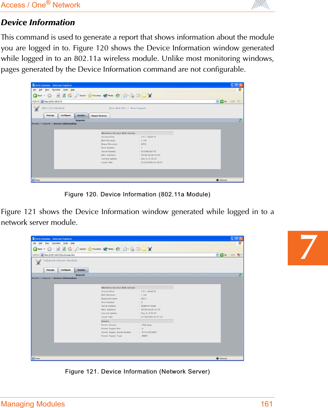
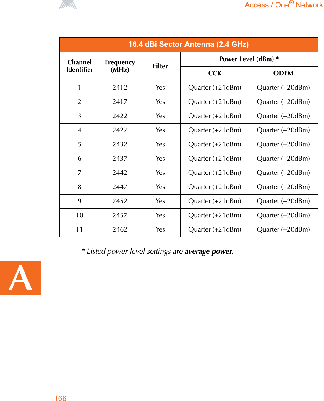
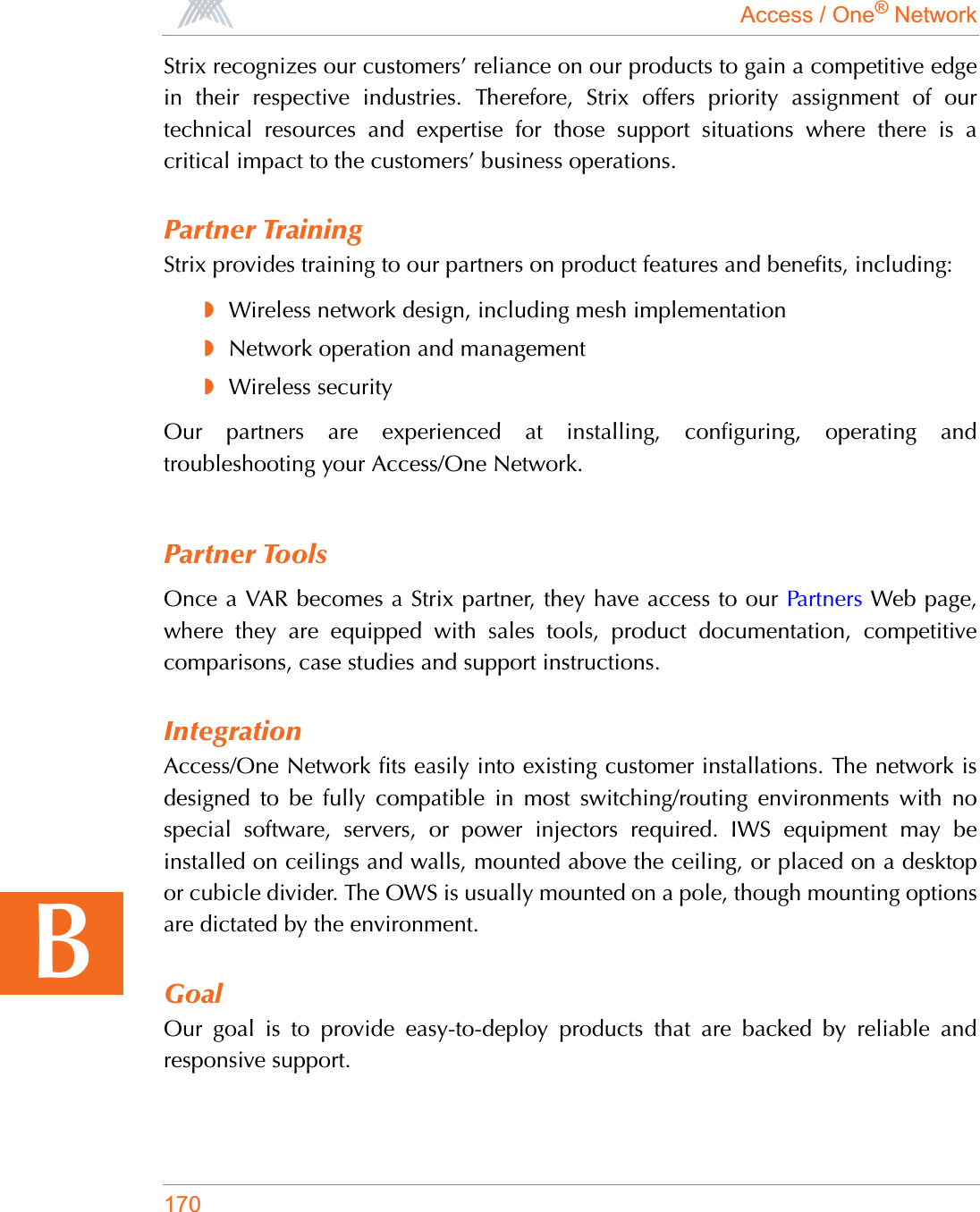
![Access / One® Network176BNOTICE Stack ID is available, stackId:XXXXXX.NOTICE The unit/Radio x will operate as - Network Connect.NOTICE The unit/Radio x will operate as - Client Connect.NOTICE The unit/Radio x will switch to - Client Connect.NOTICE Added station, mac:xx.xx.xx.xx.xx.xx.NOTICE Deauthentication completed, mac:xx.xx.xx.xx.xx.xx.NOTICE Association with AP done, response NOT sent, wlanmode:X, ssid:XXXX, mac:xx:xx:xx:xx:xx:xx.NOTICE Reassociation with AP done, response NOT sent, wlanmode:X, ssid:XXXX, mac:xx:xx:xx:xx:xx:xx.NOTICE Loop is cleared at if=XX. mac:xx:xx:xx:xx:xx:xx.NOTICE WLNC link [if=XX] state is up. SSID=XX, BSSID=xx:xx:xx:xx:xx:xx:xx, Channel=XX, Wireless Mode=XXXX.NOTICE WLNC link [if=XX] state is down.NOTICE Access Point state is up.NOTICE Access Point state is downNOTICE Association done, ssid:XXXX, vlan:[Id=x Tag=x], mac:xx:xx:xx:xx:xx:xx:xx.NOTICE Reassociation done, ssid:XXXX, vlan:[Id=x Tag=x], mac:xx:xx:xx:xx:xx:xx:xx.NOTICE Disassociation done, mac:xx:xx:xx:xx:xx:xx.NOTICE Backhaul [mac:xx:xx:xx:xx:xx:xx] at if=XXXX is approved with OPEN mode.Severity Syslog Message](https://usermanual.wiki/Strix-Systems/ACCESS-ONE-32.Users-Manual-Part-IV/User-Guide-744246-Page-64.png)
![Access / One® Network177BManagement SubsystemNOTICE Authentication failed, type=XXX, reason=XXXX, mac:xx:xx:xx:xx:xx:xx.NOTICE Authentication done, type=XXX, mac:xx:xx:xx:xx:xx:xx.NOTICE Device will switch to Access Point.Severity Syslog MessageWARNING Fan failed.WARNING Temperature alarm on.WARNING DHCP Bind failed.WARNING Image load failed.NOTICE xx.xx.xx.xx detected rogue device [xx:xx:xx:xx:xx:xx] with RSSI [xxxx] channel [xxxx] SSID [XXXXX].NOTICE Rogue device [xx:xx:xx:xx:xx:xx] detected by xx.xx.xx.xx aged out.NOTICE Detected Rogue Device [xx:xx:xx:xx:xx:xx].NOTICE Cloud is renamed to XXXXX.NOTICE Configuration update completed.NOTICE Configuration update started.NOTICE Selected AP at if=XX, mac:xx:xx:xx:xx:xx:xx.NOTICE I am the Master NC.NOTICE Temperature alarm off.NOTICE Fan is working.Severity Syslog Message](https://usermanual.wiki/Strix-Systems/ACCESS-ONE-32.Users-Manual-Part-IV/User-Guide-744246-Page-65.png)