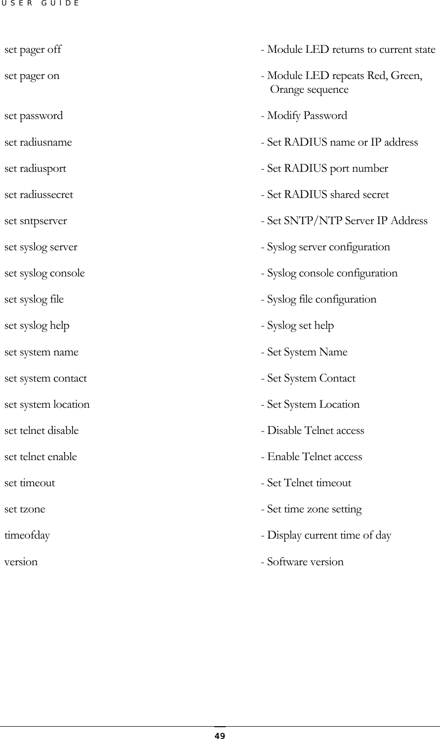
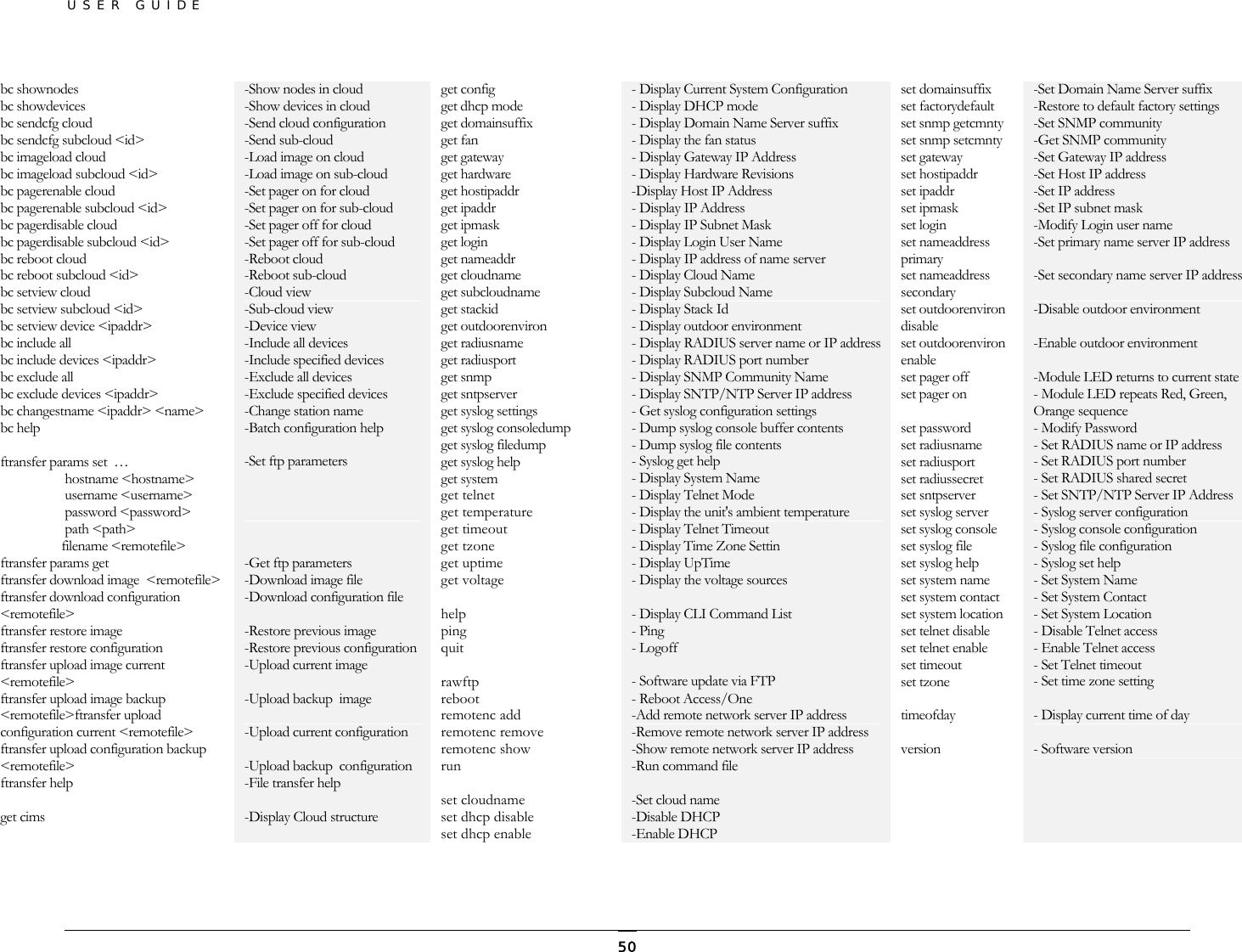
Strix Systems ACCESS-ONE-IE Access/One Network Transmitter User Manual Manual
Strix Systems, Inc. Access/One Network Transmitter Manual
UserManual.wiki
>
Strix Systems
>
ACCESS ONE IE User Manual
Users Manual Revised
Navigation menu
Upload a User Manual
Namespaces
Wiki Guide
HTML
PDF
Info
Views
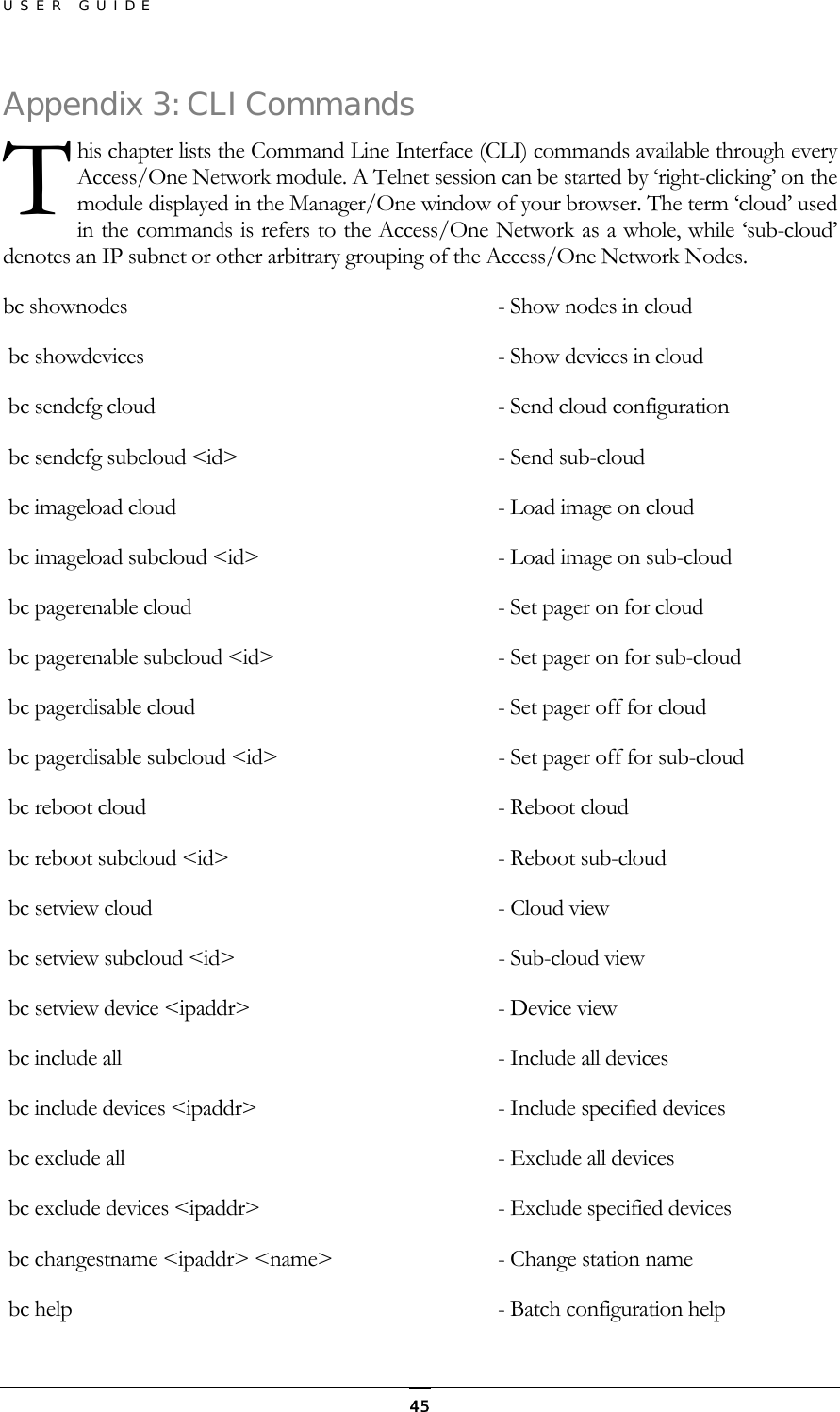
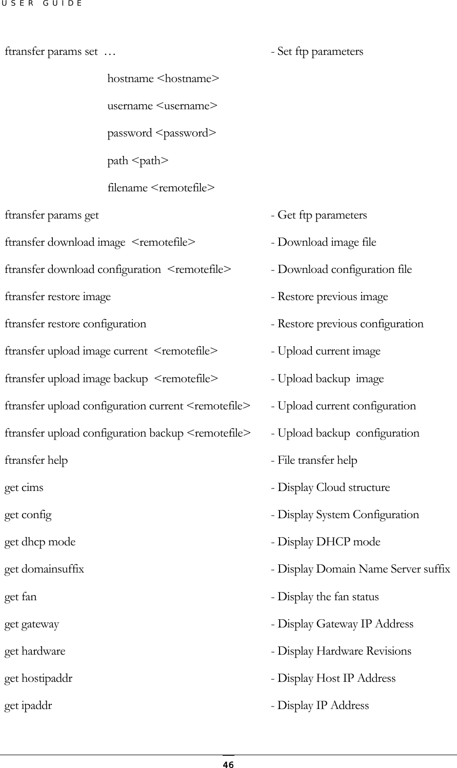
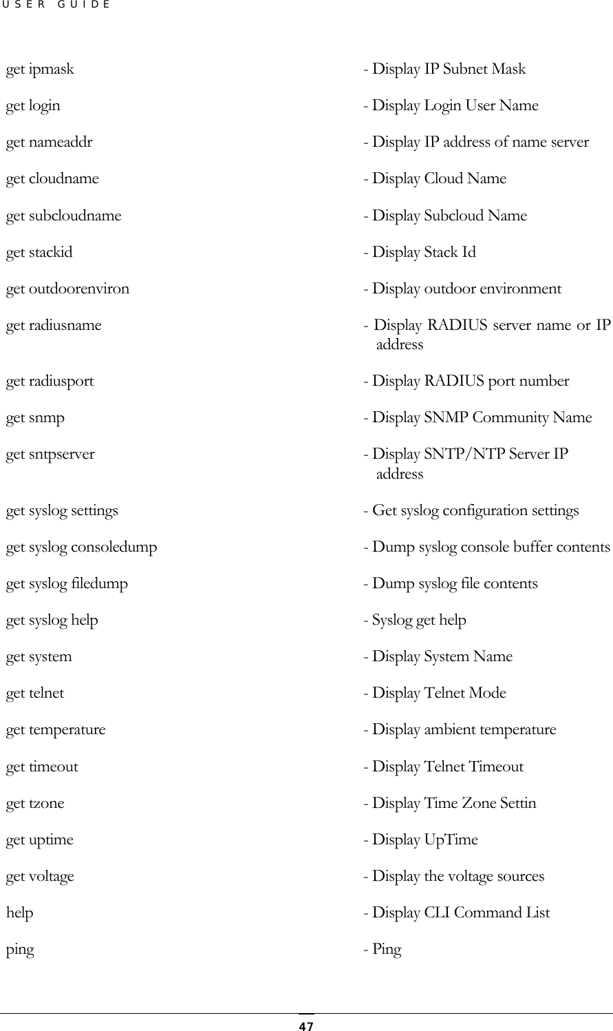
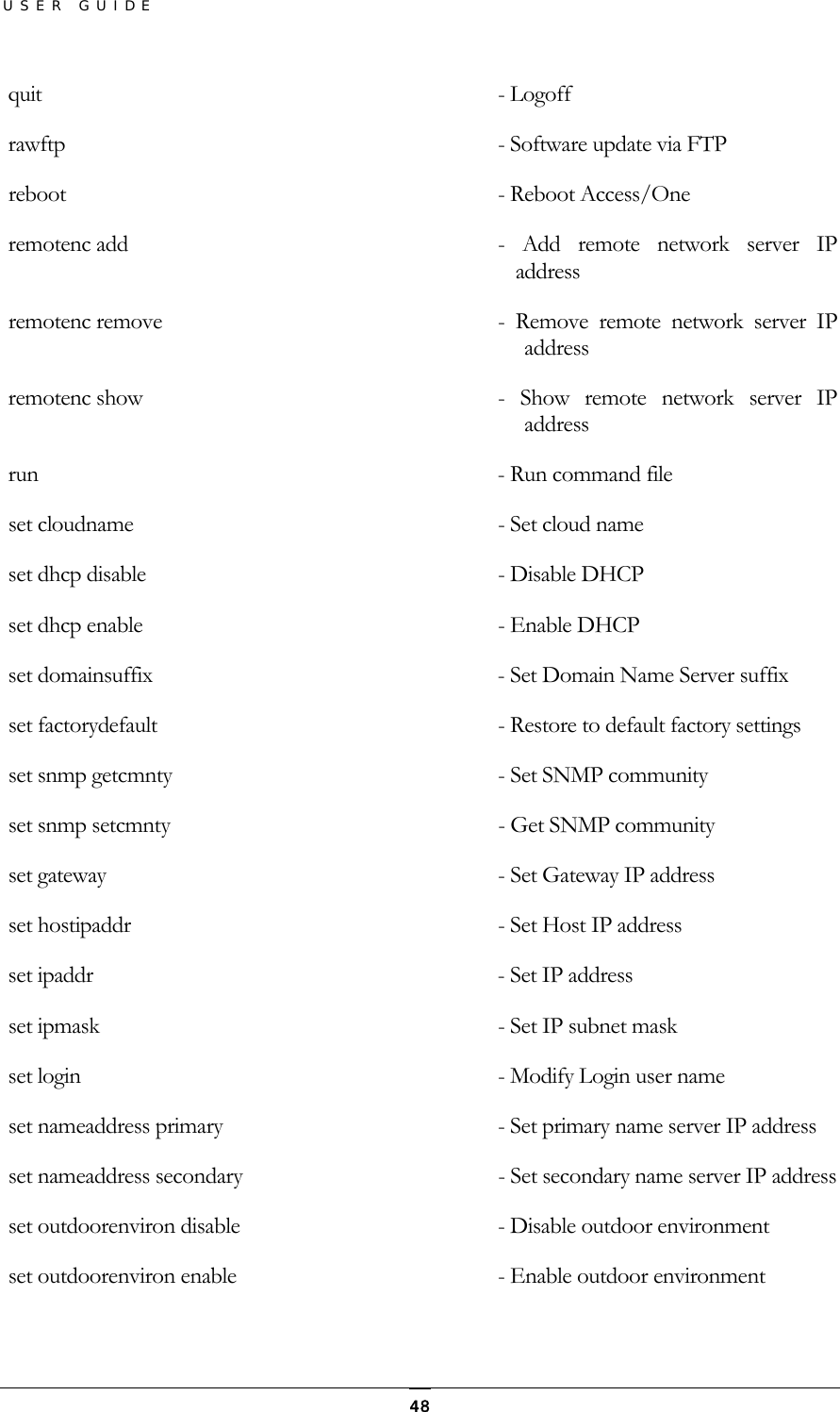
User Manual
Discussion / Help
Navigation