Strix Systems OWS2410-90 802.11 a/g Wireless Mesh Type Networking Device User Manual ows field installation guide us
Strix Systems, Inc. 802.11 a/g Wireless Mesh Type Networking Device ows field installation guide us
Contents
Users Manual 6
OWS Field Installation
Access/One®Network
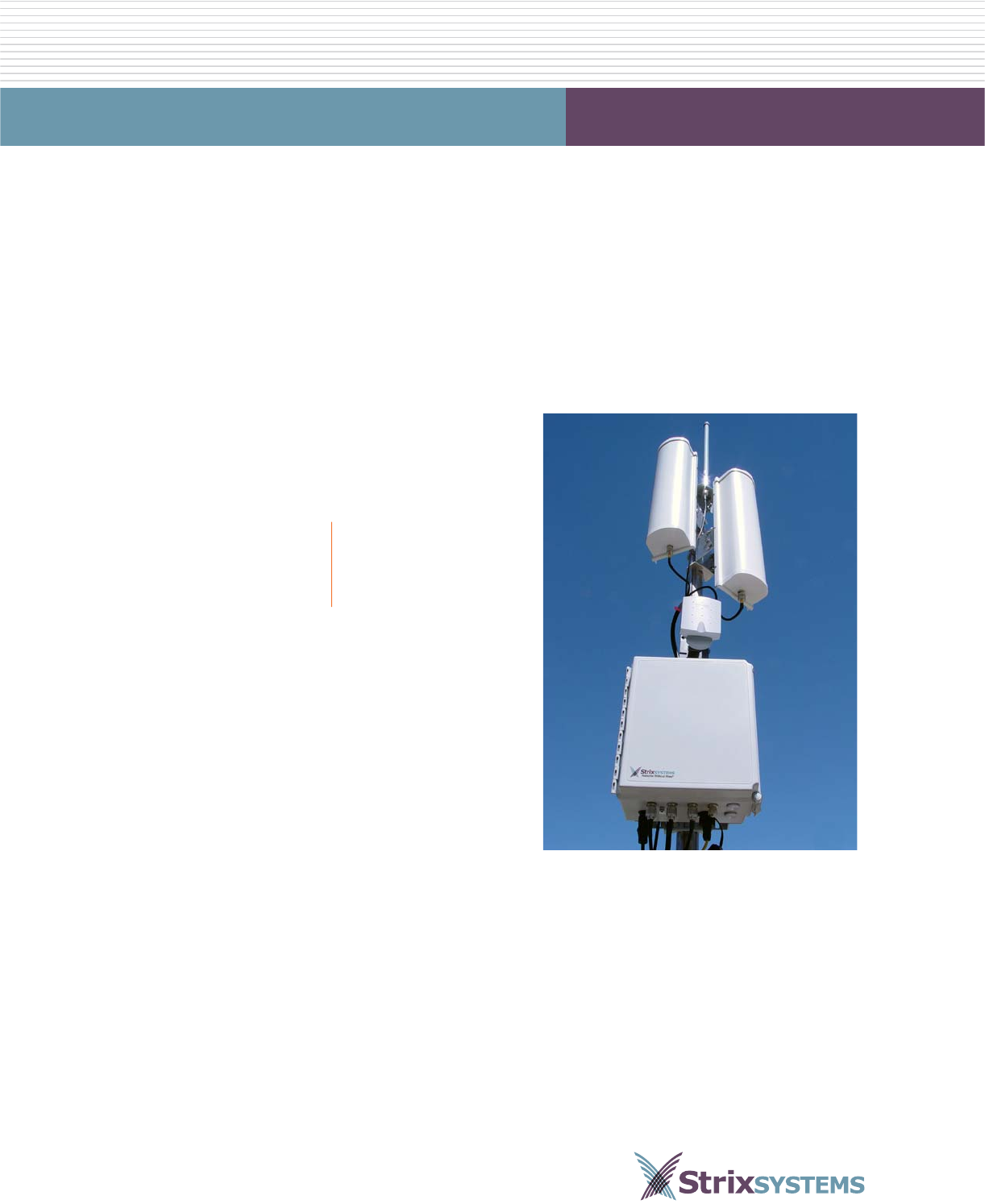
Strix Outdoor Wireless System (OWS)
Field Installation
February 8th, 2007
210-0014-01 Rev. G
Copyright © 2003 – 2007 Strix Systems, Inc.
26610 Agoura Road
Calabasas, CA 91302
USA
http://www.strixsystems.com

ii OWS Field Installation
OWS Field Installation
Copyright Notice
Copyright © 2003 – 2007 Strix Systems, Inc. All rights reserved. This document may not be reproduced or
disclosed in whole or in part by any means without the written consent of Strix Systems, Inc. Access/One
Network is a registered trademark of Strix Systems, Inc. All other trademarks and brand names are marks of
their respective holders.
FCC Notice
The enclosed wireless network device complies with Part 15 and Part 90 of the FCC Rules. Operation is
subject to the following two conditions:
1. This device may not cause harmful interference.
2. This device must accept any interference received, including interference that may cause undesired
operation.
This wireless network device has been tested and found to comply with the limits for a Class B digital device,
pursuant to Part 15 and Part 90 of the FCC Rules. These limits are designed to provide reasonable protection
against harmful interference in a residential installation. This wireless network device generates, uses, and
radiates radio frequency energy and, if not installed and used in accordance with the instructions, may cause
harmful interference to radio communications. However, there is no guarantee that interference will not
occur in a particular installation. If this wireless network device does cause harmful interference to radio or
television reception, which can be determined by turning the wireless network device off and on, the user is
encouraged to try to correct the interference by one or more of the following measures:
◗Reorient or relocate the receiving antenna.
◗Increase the separation between the wireless network device and the affected receiver.
◗Connect the wireless network device into an outlet on a circuit different from that to which the
receiver is connected.
◗Consult the dealer or an experienced radio/TV technician for help.
Other Notices
Industry Canada Notice
This Class B digital apparatus complies with Canadian ICES-003.
Cet appareil numérique de la classe B est conforme à la norme NMB-003 du Canada.
VCCI Notice
This is a Class B wireless network device based on the standard of the Voluntary Control Council for
Interference from Information Technology Equipment (VCCI). If this wireless network device is used near a
radio or television receiver in a domestic environment, it may cause radio interference. Install and use the
wireless network device according to the instruction manual.
European Community (EC) Directives and Conformity
This wireless network device is in conformity with the Essential Requirements of R&TTE Directive 1999/5/EC
of the European Union.
OWS Field Installation iii
OWS Field Installation
Non-Modification Statement
Unauthorized changes or modifications to Strix devices are not permitted. Modifications to Strix devices will
void the warranty and may violate FCC regulations.
RF Exposure Requirements
To ensure compliance with FCC RF exposure requirements, the antenna used for this wireless network device
must be installed to provide a separation distance of a minimum of 2 meters (6.56 feet) or more from all
persons, and must not be co-located or operated in conjunction with any other antenna or radio transmitter.
Installers and end-users must follow these installation instructions.
Safety Warnings
This unit must be installed by a trained professional installer only. Read the following safety warnings before
commencing an installation.
General Safety Warning
Electrical Power Warning
Lightning Activity Warning
Explosive Device Proximity Warning
Always be aware of electrical power lines!
You can be killed if any antennas come near electrical power lines. Carefully read and follow
all instructions in this manual.
By performing these installation instructions, you may be exposed to hazardous
environments and high voltage. Use caution when installing the Strix OWS product.
This unit must be installed by a trained professional installer only. Read the installation
instructions before you connect the wireless network device to its power source.
Do not connect or disconnect cables during periods of lightning activity.
For each antenna, a surge protective device meeting IEC 61000-4-5, Level 4 or IEEE C 62.41
A3/B3 requirements must be used to prevent potential damage from very high surges (for
example, surges caused by lightning).
Do not operate your wireless network device near unshielded blasting caps or in an
explosive environment.
iv OWS Field Installation
OWS Field Installation
Antenna Placement Warning
Ground Warning
Power Cord Assembly Caution
Battery Caution
Solar Shield
Do not locate any antenna near overhead power lines or other electric light or power
circuits, or where the antenna can come into contact with such circuits. When installing
antennas, take extreme care not to come into contact with such electrical circuits, as they
can cause serious injury or death.
For the correct installation and grounding of antennas, please refer to national and local
codes (for example, US:NFPA 70, National Electrical Code, Article 810; in Canada:
Canadian Electrical Code, Section 54).
You must ALWAYS install an external grounding wire. The ground connection must be
complete before connecting power to the OWS enclosure—a simple continuity check
between the enclosure and the ground termination point can confirm this. Grounding of the
OWS must comply with National Electrical Code (NEC) requirements, unless local codes in
your area take precedence over the NEC code.
An assembled power cord is not supplied with the OWS. The power cord must be assembled
by a professional installer, and the final assembly must comply with National Electrical Code
(NEC) requirements, unless local codes in your area take precedence over the NEC code.
This product contains a non-rechargeable, non-user-serviceable lithium ion battery. Exercise
caution to avoid shorting the terminals of this device.
Consult local laws and regulations for the proper disposal of batteries in your area.
A solar shield is required for any installation where the OWS product will receive direct
exposure to sunlight. Failure to install a solar shield where required may cause damage to the
product and will void its warranty. Contact your Strix authorized distributor or Strix Systems
for Solar Shield model numbers and ordering information.

OWS Field Installation v
OWS Field Installation
Limited Warranty
Strix Systems, Inc. (“Strix”) warrants the Access/One Indoor Wireless System (“IWS”) and Outdoor Wireless
System (“OWS”): (i) the hardware (“Hardware”) will be free of defects in materials and workmanship from the
date of shipment as set forth below and (ii) the embedded software (“Firmware”) to the Hardware and any
separately provided software product (“Software”) are provided “AS-IS” and such items will substantially
conform to their respective published product documentation (collectively the “Product”) for the periods
indicated below, commencing (as applicable) on the date of shipment.
This limited warranty extends only to the original user of the Product and such user's sole and exclusive
remedy and the entire liability of Strix, at its option, will be to repair or replace the Hardware or component
thereof and in the case of Firmware or Software Strix will make available the then available updated version of
the Firmware or Software. Notwithstanding the foregoing, in no event does Strix warrant that the Product will
operate with any software or hardware other than that provided by Strix or specified in the applicable Product
documentation, that the Product is error free or will operate without problems or interruptions, or that the,
Product will be free of vulnerability to intrusion or attack, or that the Product will satisfy any party's own
specific requirements. The repair or replacement of the Product does not include any labor or other costs
related to the subsequent installation thereof. The obligations of Strix hereunder are conditioned upon the
return of the Hardware in accordance with the Strix then-current Return Material Authorization (RMA)
procedures (please contact your authorized Strix Systems reseller for return instructions). Repair or
replacement of the defective Product or parts thereof shall neither extend nor decrease the warranty period.
Exceptions
The foregoing limited warranties of the Product do not apply if the Product (i) has been altered or modified,
except by Strix or its duly trained and authorized service provider, (ii) has not been installed, operated,
repaired, or maintained in accordance with written instructions of Strix, (iii) has been subjected to abnormal
physical or electrical stress, misuse, negligence or accident, (iv) has been operated outside of the
environmental specifications for the Product or (v) is related to configuration of customer's network beyond
that necessary to the use or installation of the Strix Products. The Strix limited Firmware or Software warranty
does not apply to Firmware or Software corrections or upgrades. Repair of Products or the supply of updated
Firmware or Software requested after the expiration of the warranty period shall be at then current Strix repair
or update charges.
Covered Product Warranty Period
IWS products
(Including but not limited to the BMEx, WM11x,
NWSV-x, Antennas, AMECs, MTKIT, PSWW, SLCDT
and SLCKIT)
12 months
OWS2400/OWS3600 12 months
OWS11xx (Radio Board)/OWS-NSxx (Network Servers) 12 months
Repaired or Replacement Items 90 days, or the balance of the original
item warranty, whichever is the greater

vi OWS Field Installation
OWS Field Installation
DISCLAIMER; LIMITATION OF LIABILITY
EXCEPT FOR THE WARRANTIES SPECIFICALLY DESCRIBED HEREIN, STRIX DISCLAIMS ANY AND ALL
WARRANTIES AND GUARANTEES, EXPRESS, IMPLIED OR OTHERWISE, ARISING, WITH RESPECT TO THE
PRODUCTS OR SERVICES DELIVERED HEREUNDER, INCLUDING BUT NOT LIMITED TO THE
WARRANTY OF MERCHANTABILITY, THE WARRANTY OF FITNESS FOR A PARTICULAR PURPOSE, AND
ANY WARRANTY OF NON-INFRINGEMENT OF THE INTELLECTUAL PROPERTY RIGHTS OF ANY THIRD
PARTY. LIABILITY OF STRIX FOR LOSS UNDER THIS CONTRACT IS LIMITED TO THE TOTAL AMOUNT
PAID TO STRIX BY CUSTOMER DURING THE PREVIOUS CALENDAR YEAR. STRIX WILL HAVE NO
OBLIGATION OR LIABILITY, WHETHER ARISING IN CONTRACT (INCLUDING WARRANTY), TORT
(INCLUDING ACTIVE, PASSIVE OR IMPUTED NEGLIGENCE, STRICT LIABILITY OR PRODUCT LIABILITY)
OR OTHERWISE FOR ANY SPECIAL, INCIDENTAL, CONSEQUENTIAL OR INDIRECT DAMAGES
INCLUDING BUT NOT LIMITED TO LOSS OF USE, LOSS OF DATA, BUSINESS INTERRUPTION, LOSS OF
REVENUE, LOSS OF BUSINESS OR OTHER FINANCIAL LOSS ARISING OUT OF OR IN CONNECTION
WITH ANY OF THE PRODUCTS OR OTHER GOODS OR SERVICES FURNISHED BY STRIX UNDER THIS
AGREEMENT, EVEN IF ADVISED OF THE POSSIBILITY OF SUCH DAMAGES.
STRIXSYSTEMS® (including the design) and ACCESS/ONE® are registered trademarks of Strix Systems, Inc.

OWS Field Installation vii
OWS Field Installation
Table of Contents
Copyright Notice ....................................................................................................................................ii
FCC Notice ............................................................................................................................................ii
Other Notices ........................................................................................................................................ii
Safety Warnings ....................................................................................................................................iii
General Safety Warning ..................................................................................................................iii
Electrical Power Warning ...............................................................................................................iii
Lightning Activity Warning .............................................................................................................iii
Explosive Device Proximity Warning ..............................................................................................iii
Antenna Placement Warning .......................................................................................................... iv
Ground Warning ............................................................................................................................ iv
Power Cord Assembly Caution ....................................................................................................... iv
Battery Caution ............................................................................................................................... iv
Solar Shield .................................................................................................................................... iv
Limited Warranty ................................................................................................................................... v
Table of Contents ........................................................................................................................vii
OWS Field Installation ................................................................................................................. 1
Theory of Operation ...............................................................................................................................1
Important Safety Information ..................................................................................................................1
Planning Your Installation ......................................................................................................................2
Local Guidelines .............................................................................................................................2
Site Surveys .....................................................................................................................................2
Power Source ..................................................................................................................................2
Installing the OWS Enclosure .................................................................................................................3
Mounting the OWS on a Vertical Pole .............................................................................................3
Mounting the OWS on a Wall .........................................................................................................7
Installing Antennas .................................................................................................................................8
Notes About Antenna Installations ...................................................................................................8
Maximum Power Settings for Antennas ............................................................................................9
Channels for IEEE 802.11b/g .....................................................................................................9
Channels for IEEE 802.11a ......................................................................................................10
Channels for IEEE 802.11a (Public Safety) ...............................................................................11
Attaching an Omni Antenna Directly to the OWS Enclosure .........................................................12
Mounting a Directional Antenna on a Pole ....................................................................................14
Mounting a Sectored Antenna on a Pole ........................................................................................16

viii OWS Field Installation
OWS Field Installation
Mounting an Omni Antenna on a Pole ..........................................................................................19
Antenna Connector Wiring Configurations ...........................................................................................22
Physical Layout (Enclosure) ...........................................................................................................22
Physical Layout (Wireless Modules) ...............................................................................................23
Routing the Antenna Cables .................................................................................................................23
Grounding the OWS Enclosure ............................................................................................................24
Configuring the Power Cord .................................................................................................................25
AC Wiring Configurations ..............................................................................................................27
Connecting the Ethernet Cable .............................................................................................................28
Powering Up the OWS .........................................................................................................................30
Powering Up from an AC Power Source ........................................................................................30
Powering Up from a DC Power Source ..........................................................................................30
OWS Product Specifications ................................................................................................................31
Appendix I: Setting the Output Power ..................................................................................................32
Appendix II: Installing the Band Pass Filter ...........................................................................................33
Index .......................................................................................................................................... 35

OWS Field Installation 1
OWS Field Installation
OWS Field Installation
This field installation manual provides instructions for installing the Strix OWS 2400 and OWS 3600 products
safely and is intended for trained technical professionals. You must read the Safety Warnings on page iii
before commencing with the installation.
Theory of Operation
The Strix Systems, Access/One® Network OWS provides up to 3 independent channels for 802.11g support
and 3 independent channels of 802.11a and 4.9 GHz (public safety) support through its external connections.
This configuration allows the installer to separate the client 802.11g traffic from the backhaul traffic which is
carried through the 802.11a channels.
As shipped from the factory, the OWS is self-configuring and self-healing. In addition, multiple configuration
options are possible and the installer should refer to the Access/One® Network User's Guide (part number
210-0007-01) for detailed information about these configurations.
Important Safety Information
The Federal Communications Commission (FCC) with its action in ET Docket 96-8 has adopted a safety
standard for human exposure to RF electromagnetic energy emitted by FCC certified equipment. All Strix
products, including the OWS, meet the uncontrolled environmental limits found in OET-65 and ANSI
C95.1, 1991. The proper operation of this wireless device, according to the instructions found in this
manual and the associated Access/One® Network software User’s Guide, result in user exposure that is
substantially below the FCC recommended limits.
The following are guidelines to ensure safe operation of the Strix OWS product:
◗Do not touch or move the antenna(s) while the unit is transmitting or receiving.
◗Do not hold any component containing a radio such that the antenna is very close to or touching any
exposed parts of the body—especially the face or eyes—while transmitting.
◗Do not operate the OWS or attempt to transmit data unless the antenna (or a 50 ohm terminator) is
connected, otherwise the wireless module(s) may be damaged.
◗Usage in specific environments:
–Do not operate any wireless equipment near unshielded blasting caps or in an explosive
environment.
–The use of wireless devices in hazardous locations is limited to the constraints posed by the safety
directors or such environments.
–The use of wireless devices on airplanes is governed by the Federal Aviation Administration (FAA).
–The use of wireless devices in hospitals is restricted to the limits set forth by each hospital.
◗The Strix OWS must only be used with Strix-approved components and antennas, or equivalent.

2OWS Field Installation
OWS Field Installation
Planning Your Installation
To ensure safe and durable wiring, the installation of the Strix OWS must follow the appropriate electrical and
building codes. Observe the National Electrical Code (NEC) requirements, unless local codes in your area
take precedence over the NEC code.
Local Guidelines
The Strix OWS is a radio device and therefore susceptible to interference that can reduce throughput and
range. Follow these simple guidelines to optimize product performance:
◗Install the OWS in an area where trees, buildings, and large steel structures do not obstruct radio
signals to and from the antenna(s). Direct line-of-sight operation is always best.
◗Install the OWS away from microwave ovens or other devices operating in the 2.4 GHz range.
◗Install the OWS away from other possible source of 2.4 GHz WLAN interference, such as cordless
phones, home surveillance equipment, frequency-hopping (FHSS) and DSSS Local Area Network
transceivers, electronic news gathering video links, radars, amateur radios, land mobile radio services,
local government sties (for example, law enforcement), fixed microwave services, local TV
transmission, and private fixed point transmitters.
Site Surveys
Due to variations in product configuration, placement, and the physical environment, each installation is
unique. Before installing the Strix OWS, we recommend that you perform a site survey to determine the
optimum placement of the product to achieve the best possible range, coverage and network performance.
Consider the following points:
◗Data Rates—Sensitivity and range are inversely proportional to data bit rates. The maximum wireless
range is achieved at the lowest data rate. A decrease in receiver threshold sensitivity occurs as wireless
data increases.
◗Antenna Type and Placement—Using the correct antenna configuration is a critical factor when trying
to maximize wireless range. As a general rule, the range increases in proportion to the antenna height
and gain.
◗Physical Environment—Clear or open areas offer better wireless coverage than closed or filled areas.
The less cluttered the operating environment, the greater the range.
◗Obstructions—A physical obstruction, such as a building or tree, can block or hinder wireless services.
Avoid placing antennas in locations where there is an obstruction between the sending and receiving
antennas.
◗Building Materials—Wireless penetration is influenced by the building materials used in construction.
For example, drywall construction permits greater range than concrete blocks. Steel and alloy materials
can be a barrier to wireless signals.
◗Diversity—The Strix OWS supports RX diversity, which requires two antennas.
Power Source
The Strix OWS supports both AC and DC input power.
OWS Field Installation 3
OWS Field Installation
Installing the OWS Enclosure
This section provides instructions for mounting the OWS enclosure.
Mounting the OWS on a Vertical Pole
Parts Required
◗OWS enclosure.
◗Pole.
◗2 vertical mounting brackets.
◗4 screws and 4 spacers, for attaching the mounting brackets to the OWS enclosure.
◗2 U-bolt assemblies, for mounting the OWS enclosure to a standard 1 7/8 inch diameter steel pole.
◗2 straps, for mounting the OWS enclosure to a pole with a diameter greater than 1 7/8 inches.
Tools Required
◗Flat blade screwdriver
◗5/16 inch nut driver
◗7/16 inch nut wrench
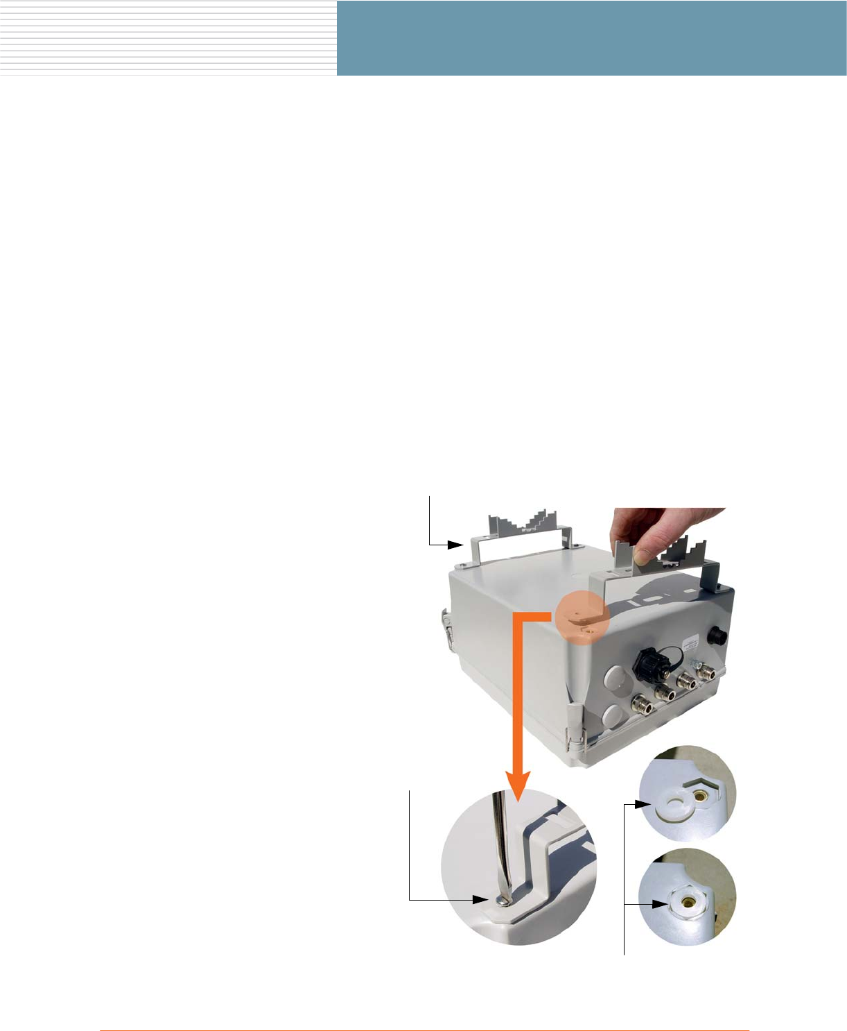
1. Insert the spacers (provided) in
the four recessed mounting holes
(2 for each bracket).
2. Attach the vertical mounting
brackets (2) to the OWS
enclosure.
3. Secure the vertical mounting
brackets to the OWS enclosure
with the four screws (2 for each
bracket).
Tighten all four screws to 10–12
lbf.ft (1.38–1.66 kgf.m).
Do not overtighten the screws.
Screws (x4)
Mounting Brackets (x2)
Spacers (x4)
4OWS Field Installation
OWS Field Installation
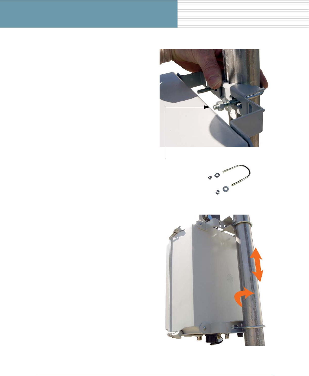
4. For a standard 1 7/8 inch
diameter steel pole installation,
use the 2 U-bolt assemblies to
attach the enclosure to the pole
via the vertical mounting
brackets—finger tighten only.
If installing the OWS on a wider
pole (for example, a utility pole),
go directly to Step 8—skip Steps
3 through 6.
Tip: You may find it easier to
loosely attach the U-bolts to the
brackets, then slide the
completed enclosure assembly
over the pole (instead of holding
the enclosure against the pole
and attaching each U-bolt
separately).
5. Adjust the OWS enclosure to the
desired position on the pole (up
and down or rotational).
U-Bolt Assembly (x2)
Includes:
◗U-bolt
◗Washers (2)
◗Nuts (2)
OWS Field Installation 5
OWS Field Installation
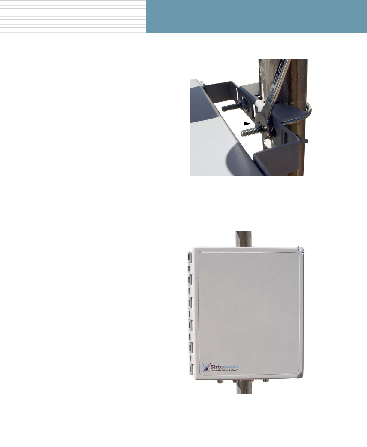
6. Use a 7/16 inch nut wrench to
tighten the U-bolts (4 nuts) and
secure the OWS enclosure in
place.
Tighten all four nuts to 10–12
lbf.ft (1.38–1.66 kgf.m).
When tightening the U-bolts,
ensure that the bolts are not
twisted—the ends of each U-bolt
should be protruding through the
bracket evenly (the same
distance).
7. Check that the U-bolts are tight
and that the OWS enclosure is
securely anchored to the pole.
Tighten (4 places)
6OWS Field Installation
OWS Field Installation
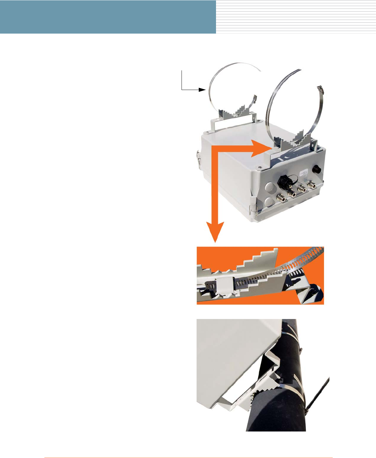
8. For poles wider than 1 7/8 inch
diameter, use two straps (hose
clamps)—not provided. Feed one
strap through each of the vertical
mounting brackets.
Recommended straps:
Type 301 SS with Type 305 SS
screw, 3.125 x 6 inches, available
from McMaster-Carr (part
number 54155K36).
9. Loosely attach the OWS
enclosure to the pole with the 2
straps.
Adjust the enclosure to the
desired position on the pole (up
and down or rotational). Use a
flat blade screwdriver or 5/16
inch nut driver to tighten both
straps to 10–12 lbf.ft (1.38–1.66
kgf.m).
Straps (x2)
OWS Field Installation 7
OWS Field Installation
Mounting the OWS on a Wall
Parts Required
◗OWS enclosure.
◗4 nylon hangers, for mounting the OWS enclosure to a wall.
◗4 screws (10-32 x 0.375), for attaching the nylon hangers to the enclosure.
Tools Required
◗Flat blade screwdriver ◗Power drill and drill bit (if necessary)
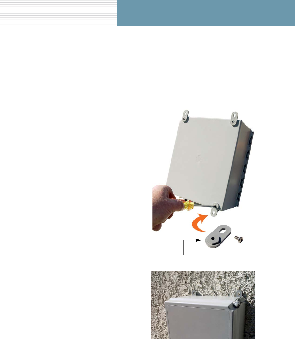
1. Attach the 4 nylon hangers to the
OWS enclosure using the 4
screws provided.
2. Mount the OWS enclosure to any
wall surface, ensuring that the
unit is level and secure (4 places).
If mounting the enclosure to a
masonry wall, you will need a
power drill, masonry drill bit, and
wall plugs.
Nylon Hanger (x4)
8OWS Field Installation
OWS Field Installation
Installing Antennas
This section provides instructions for installing and connecting antennas. The antennas shown in this section
are a representative sample only and are provided as a guideline for installation—your specific antenna(s)
may be different, in which case refer to the instructions provided with the antenna(s).
Antenna Warning
Applying Power Before an Antenna is Connected
Strong RF Fields are Present
Notes About Antenna Installations
Read the following notes before installing any antenna.
◗The system installer should always ensure that antenna radiation patterns do not overlap.
◗A sector antenna should point towards the center of the sector covered by the antenna.
◗Fixed point-to-point backhaul antennas should point towards the desired Strix Systems Access/One®
Network device intended for the backhaul connection.
◗Unused antenna ports must be terminated with a 50 ohm terminator.
◗Only antennas approved by Strix Systems (or equivalent) may be used with the Access/One® Network
Outdoor Wireless System (OWS).
◗Only one antenna may be used on each antenna port.
◗When installing antennas that require mounting brackets and U-bolts, it is easier to loosely attach the
U-bolts to the brackets, then slide the completed antenna assembly over the pole (instead of holding
the assembly against the pole and attaching each U-bolt separately—mounting brackets are shipped
with the U-bolts pre-assembled. For this reason, do not install an omni antenna at the top of the pole
before installing any directional/sectored antennas that will reside below it.
Antennas must be installed by a trained professional installer only.
Do not locate any antenna near overhead power lines or other electric light or power
circuits, or where the antenna can come into contact with such circuits. When
installing antennas, take extreme care not to come into contact with such electrical
circuits, as they can cause serious injury or death.
For the correct installation and grounding of antennas, please refer to national and local
codes (for example, US:NFPA 70, National Electrical Code, Article 810; in Canada:
Canadian Electrical Code, Section 54).
Do not apply power to the transmitter until the antenna is connected, otherwise
permanent damage may result.
When the unit is operation, avoid standing directly in front of the antenna. Strong RF
fields are present when the transmitter is ON.

OWS Field Installation 9
OWS Field Installation
◗Depending on the selected antenna(s) for your application, it may be necessary to configure the output
power of your OWS 2400 or OWS 3600 product. It is the installer’s responsibility to ensure the output
power is set correctly for the chosen antenna(s). To set the output power, go to Appendix I: Setting the
Output Power on page 32. Operation of the OWS 2400 or OWS 3600 in a manner other than as
represented here is a violation of FCC rules.
Maximum Power Settings for Antennas
The following table shows the maximum power settings based on the type of antenna1 being used and the
wireless band.
Channels for IEEE 802.11b/g
* Listed power level settings are average power.
1. In order to comply with FCC regulations, for transmissions in the 5.725 - 5.850 GHz
band using the 23 dBi Patch Panel antenna in the United States, a band pass filter must
be used (K&L Microwave part number 6C50-5787.5/U120-n/n or equivalent), and also
for transmissions in the 2.4 GHz band in the United States using full power on channels
1 or 11 (RF Linx Corporation part number 2400BPF-8-FB or equivalent).
12 dBi Omni Antenna (2.4 GHz)
Channel
Identifier
Frequency
(MHz) Filter
Power Level (dBm) *
CCK ODFM
1 2412 Yes Half (+24dBm) Half (+23dBm)
2 2417 Yes Half (+24dBm) Half (+23dBm)
3 2422 Yes Half (+24dBm) Half (+23dBm)
4 2427 Yes Half (+24dBm) Half (+23dBm)
5 2432 Yes Half (+24dBm) Half (+23dBm)
6 2437 Yes Half (+24dBm) Half (+23dBm)
7 2442 Yes Half (+24dBm) Half (+23dBm)
8 2447 Yes Half (+24dBm) Half (+23dBm)
9 2452 Yes Half (+24dBm) Half (+23dBm)
10 2457 Yes Half (+24dBm) Half (+23dBm)
11 2462 Yes Half (+24dBm) Half (+23dBm)

10 OWS Field Installation
OWS Field Installation
* Listed power level settings are average power.
Channels for IEEE 802.11a
* Listed power level settings are average power.
16.4 dBi Sector Antenna (2.4 GHz)
Channel
Identifier
Frequency
(MHz) Filter
Power Level (dBm) *
CCK ODFM
1 2412 Yes Quarter (+21dBm) Quarter (+20dBm)
2 2417 Yes Quarter (+21dBm) Quarter (+20dBm)
3 2422 Yes Quarter (+21dBm) Quarter (+20dBm)
4 2427 Yes Quarter (+21dBm) Quarter (+20dBm)
5 2432 Yes Quarter (+21dBm) Quarter (+20dBm)
6 2437 Yes Quarter (+21dBm) Quarter (+20dBm)
7 2442 Yes Quarter (+21dBm) Quarter (+20dBm)
8 2447 Yes Quarter (+21dBm) Quarter (+20dBm)
9 2452 Yes Quarter (+21dBm) Quarter (+20dBm)
10 2457 Yes Quarter (+21dBm) Quarter (+20dBm)
11 2462 Yes Quarter (+21dBm) Quarter (+20dBm)
12 dBi Omni Antenna (5.745 – 5.825 GHz)
Channel
Identifier
Frequency
(MHz) Filter
Power Level (dBm) *
ODFM
149 5745 No Half (+23dBm)
153 5765 No Full (+26dBm)
157 5765 No Full (+26dBm)
161 5805 No Full (+26dBm)
165 5825 No Half (+23dBm)

OWS Field Installation 11
OWS Field Installation
* Listed power level settings are average power.
Channels for Public Safety (4.9 GHz)
* Listed power level settings are peak power.
23 dBi Patch Panel Antenna (5.745 – 5.825 GHz)
Channel
Identifier
Frequency
(MHz) Filter
Power Level (dBm) *
ODFM
149 5745 Yes Half (+23dBm)
153 5765 Yes Full (+26dBm)
157 5765 Yes Full (+26dBm)
161 5805 Yes Full (+26dBm)
165 5825 Yes Half (+23dBm)
11 dBi Radome Omni Antenna (4.940 GHz – 4.990 GHz)
Channel
Identifier
Frequency
(MHz) Filter
Power Level (dBm) *
ODFM
30 4955 No Full (+30.7dBm)
70 4975 No Full (+30.7dBm)
12 OWS Field Installation
OWS Field Installation
Attaching an Omni Antenna Directly to the OWS Enclosure
Parts Required
◗Omni Antenna, with optional adapter (no special tools required).
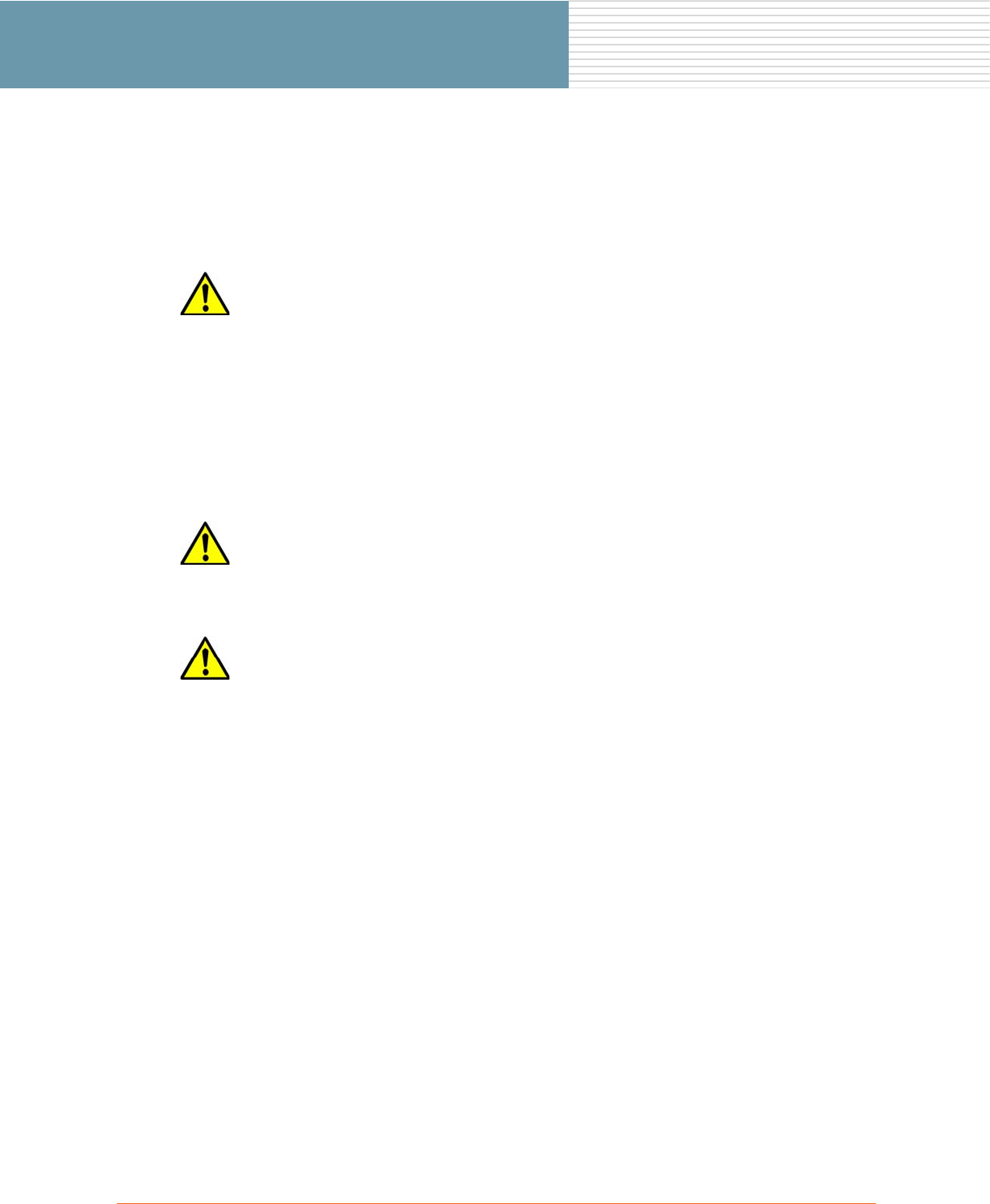
1. If necessary, connect the optional
antenna adapter to the desired
antenna port at the bottom of the
OWS enclosure.
Hand tighten, making sure the
adapter is firmly in place—you
can use an adjustable wrench,
but do not overtighten or damage
the adapter.
Adapter
OWS Field Installation 13
OWS Field Installation
2. Thread the omni antenna onto
the antenna adapter—the
electrical connection between
the antenna and the enclosure is
established via the adapter.
There are no external cables
required when attaching an omni
antenna directly to the OWS
enclosure.
See also, Antenna Connector
Wiring Configurations on
page 22.
Adapter
Omni Antenna

14 OWS Field Installation
OWS Field Installation
Mounting a Directional Antenna on a Pole
Parts Required
◗Pole.
◗Directional antenna (includes adjustable mounting bracket).
◗2 straps, for mounting the antenna to a standard 1 7/8 inch diameter steel pole.
◗Antenna cable.
Tools Required
◗Flat blade screwdriver
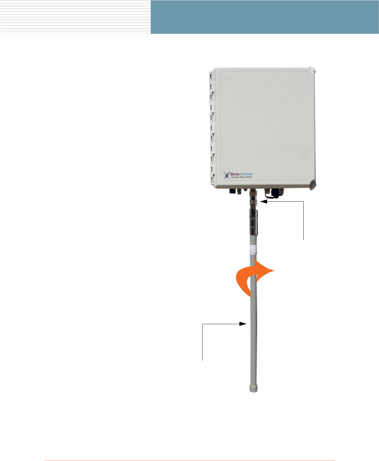
1. Attach the 2 straps (hose clamps)
to the mounting bracket.
2. Mount the antenna to the pole
with the 2 straps.
Adjust the antenna to the desired
position, then use a flat blade
screwdriver or 5/16 inch nut
driver to tighten both straps to
10–12 lbf.ft (1.38–1.66 kgf.m).
Antenna
Straps (x2)
OWS Field Installation 15
OWS Field Installation
3. Using a flat blade screwdriver,
fine tune the position of the
antenna by adjusting the
mounting bracket along the
vertical axis and the horizontal
axis.
Tighten the mounting bracket
adjustment screws to 10–12 lbf.ft
(1.38–1.66 kgf.m).
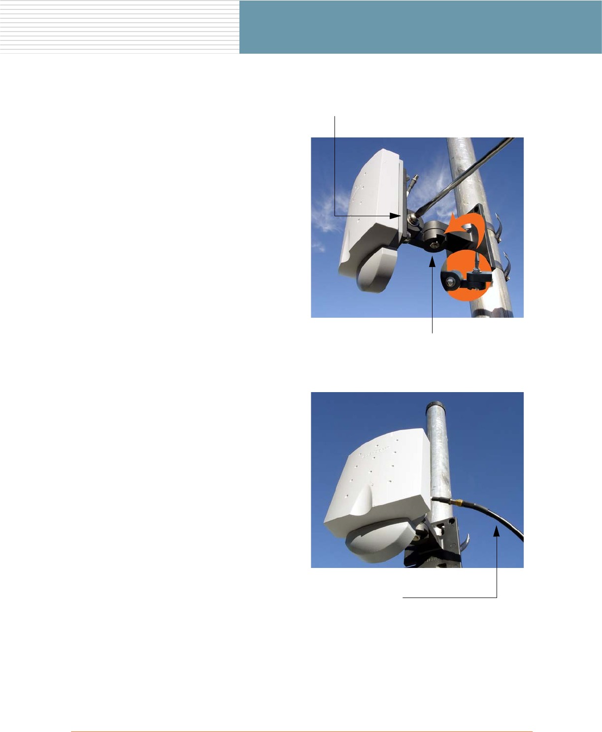
4. Connect one end of the antenna
cable to the directional antenna,
then connect the other end of the
cable to an available antenna
port on the OWS enclosure.
See also, Antenna Connector
Wiring Configurations on
page 22 and Antenna Connector
Wiring Configurations on
page 22.
Vertical Adjustment
Horizontal Adjustment
Antenna Cable
Connect between the directional
antenna and a free antenna port on
the OWS enclosure
16 OWS Field Installation
OWS Field Installation
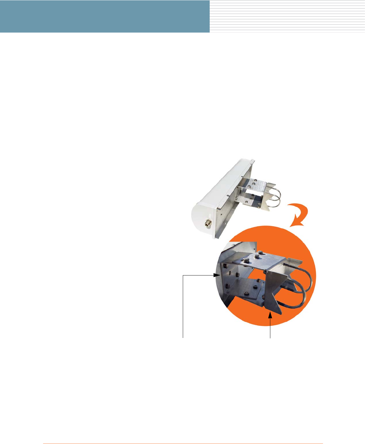
Mounting a Sectored Antenna on a Pole
Parts Required
◗Pole.
◗Sectored antenna.
◗2 U-bolt assemblies, for mounting the antenna to a standard 1 7/8 inch diameter steel pole.
◗Adjustable mounting bracket (including antenna mounting plate and U-bolt assemblies).
◗Antenna cable.
Tools Required
◗7/16 inch nut wrench
1. If not already assembled,
assemble the adjustable
mounting bracket.
Secure the antenna mounting
plate to the antenna body with 4
x 7/16 inch screws and spring
washers. Use a 7/16 inch nut
wrench to tighten the screws to
10–12 lbf.ft (1.38–1.66 kgf.m).
Attach the mounting bracket to
the antenna mounting plate with
6 x 7/16 inch screws and spring
washes—finger tighten only.
The U-bolts are pre-assembled
with the mounting bracket.
Antenna Mounting Plate Mounting Bracket
Secure to antenna body
with 4 x 7/16 inch screws
and spring washers
Attach to mounting plate
with 6 x 7/16 inch screws
and spring washers—finger
tighten only
OWS Field Installation 17
OWS Field Installation
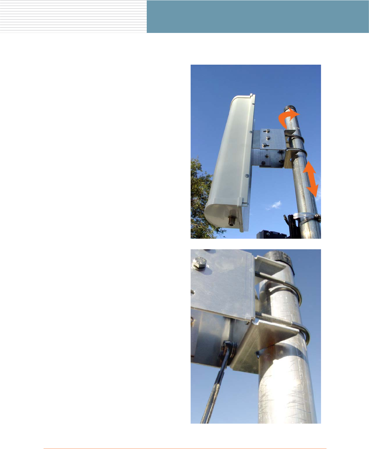
2. Attach the sectored antenna to
the pole—finger tighten only.
3. Adjust the antenna to the desired
position on the pole (up and
down or rotational).
4. Use a 7/16 inch nut wrench to
tighten the U-bolts (4 nuts) and
secure the sectored antenna in
place.
Tighten all four nuts to 10–12
lbf.ft (1.38–1.66 kgf.m).
When tightening the U-bolts,
ensure that the bolts are not
twisted—the ends of each U-bolt
should be protruding through the
mounting bracket evenly (the
same distance).
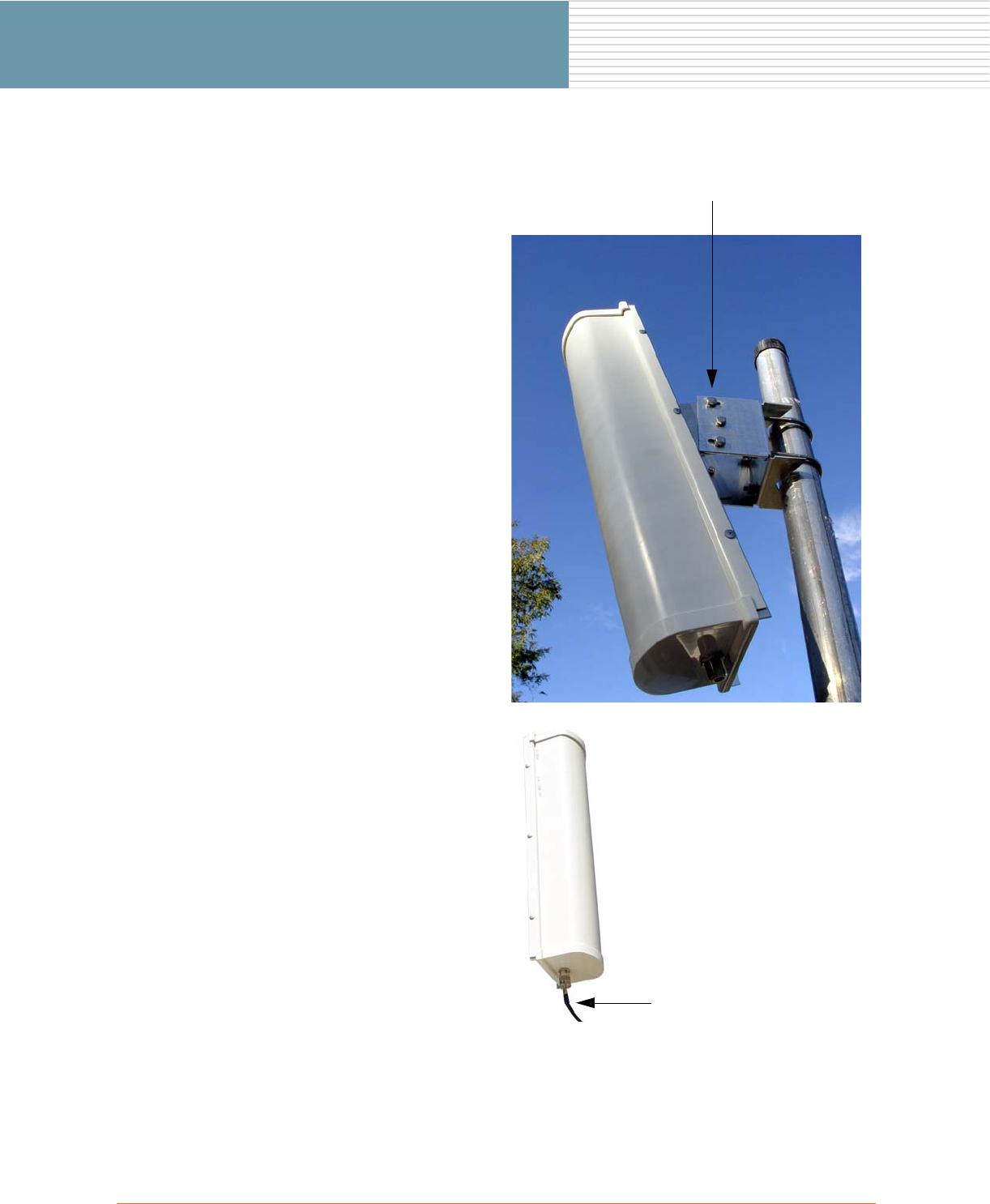
18 OWS Field Installation
OWS Field Installation
5. If necessary, use a 7/16 inch nut
wrench to loosen the 6 bolts on
the adjustable mounting bracket.
Make your vertical adjustment to
the sectored antenna (up to 30
degrees), then tighten all 6 bolts
to 10–12 lbf.ft (1.38–1.66 kgf.m).
6. Connect one end of the antenna
cable to the sectored antenna,
then connect the other end of the
cable to an available antenna
port on the OWS enclosure.
See also, Antenna Connector
Wiring Configurations on
page 22 and Antenna Connector
Wiring Configurations on
page 22.
Vertical Adjustment (up to 30 degrees)
Antenna Cable
Connect between the
sectored antenna and a
free antenna port on the
OWS enclosure
OWS Field Installation 19
OWS Field Installation
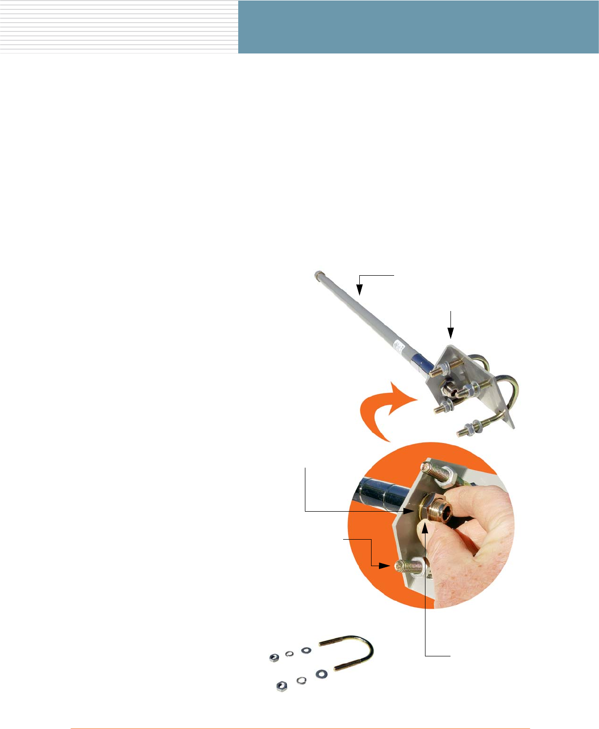
Mounting an Omni Antenna on a Pole
Parts Required
◗Pole.
◗Omni antenna.
◗2 U-bolt assemblies, for mounting the antenna to a standard 1 7/8 inch diameter steel pole.
◗Mounting bracket.
◗Antenna cable.
Tools Required
◗1/2 inch nut wrench ◗7/8 inch nut wrench
1. Attach the omni antenna to the
mounting bracket, using the
washer and locknut provided.
The U-bolts are pre-assembled
with the mounting bracket.
2. Use a 7/8 inch nut wrench to
tighten the locknut to 10–12 lbf.ft
(1.38–1.66 kgf.m).
U-Bolt Assembly (x2)
Omni Antenna
Mounting Bracket
Includes:
◗U-bolt
◗Plain washers (2)
◗Spring washers (2)
◗Nuts (2)
Locknut
Washer
20 OWS Field Installation
OWS Field Installation
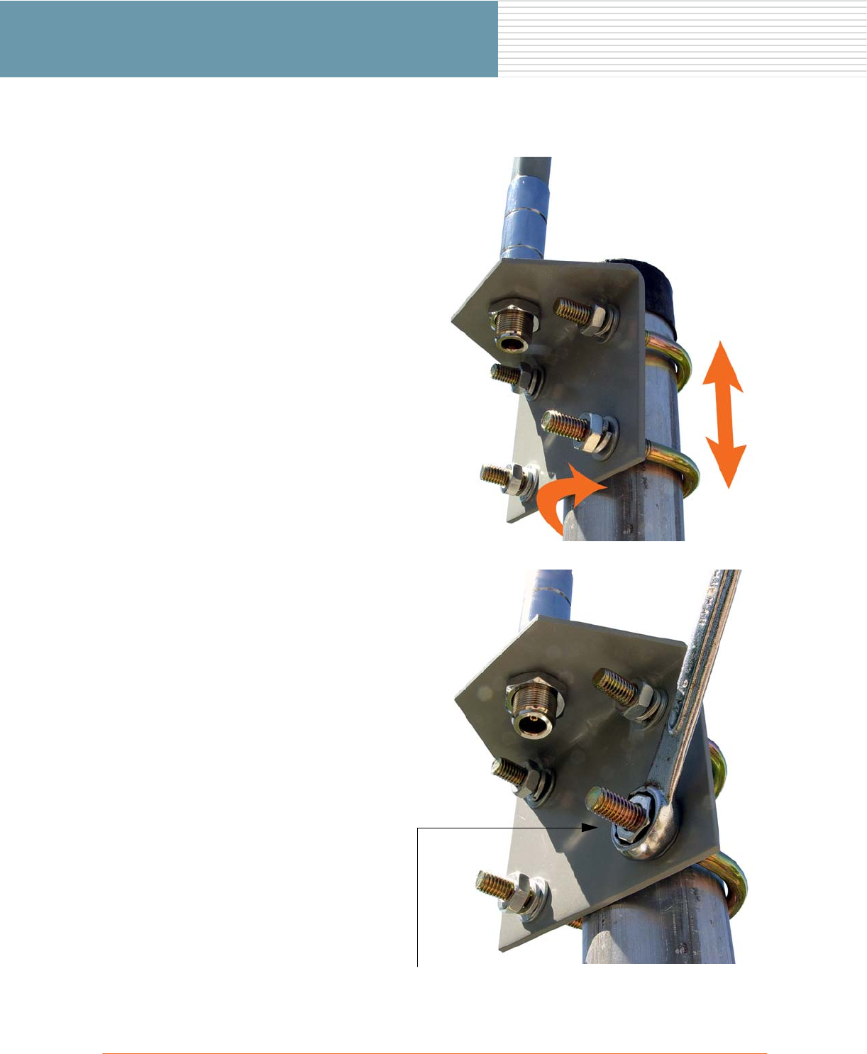
3. Attach the omni antenna to the
pole—finger tighten only.
4. Adjust the omni antenna to the
desired position on the pole (up
and down or rotational).
5. Use a 1/2 inch nut wrench to
tighten the U-bolts (4 nuts) and
secure the omni antenna in
place.
Tighten all four nuts to 10–12
lbf.ft (1.38–1.66 kgf.m).
When tightening the U-bolts,
ensure that the bolts are not
twisted—the ends of each U-bolt
should be protruding through the
mounting bracket evenly (the
same distance).
Tighten (4 places)
OWS Field Installation 21
OWS Field Installation
6. Check that the U-bolts are tight
and that the omni antenna is
securely anchored to the pole.
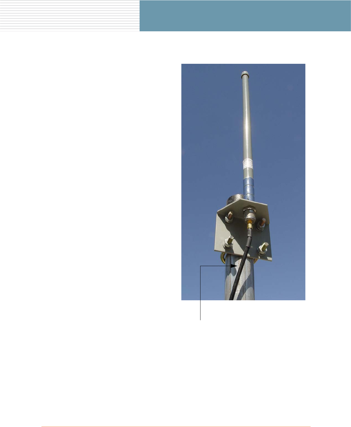
7. Connect one end of the antenna
cable to the omni antenna, then
connect the other end of the
cable to an available antenna
port on the OWS enclosure.
See also, Antenna Connector
Wiring Configurations on
page 22 and Antenna Connector
Wiring Configurations on
page 22.
Antenna Cable
Connect between the omni
antenna and a free antenna port on
the OWS enclosure
22 OWS Field Installation
OWS Field Installation
Antenna Connector Wiring Configurations
The following table shows the antenna connector wiring configurations for the OWS family of products:
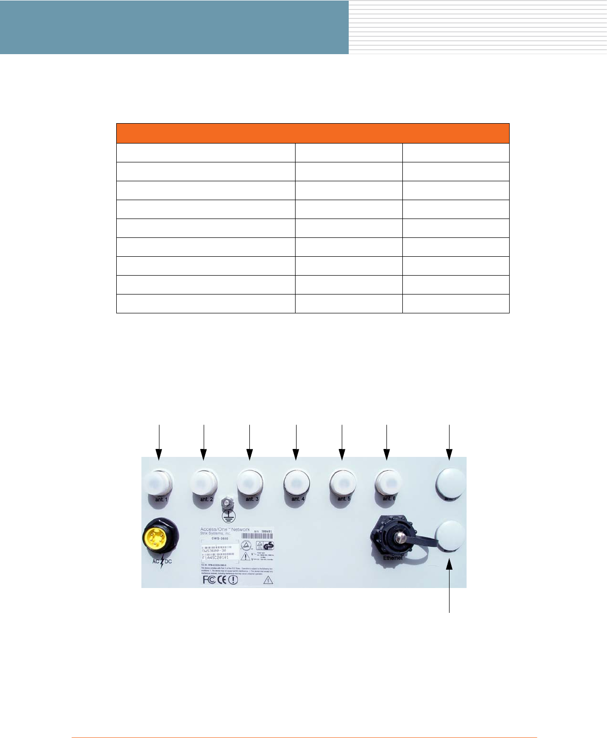
Physical Layout (Enclosure)
The following diagram shows the physical layout of antenna connectors on the OWS 3600 enclosure (the
OWS 2400 does not have the ant. 7 or ant. 8 antenna options).
Antenna Connector Wiring
Product Enclosure Connector Module Connector
2400 series and 3600 series ant. 1 G ANT1 – J24
2400 series and 3600 series ant. 2 A ANT1 – J21
2400 series and 3600 series ant. 3 G ANT1 – J24
2400 series and 3600 series ant. 4 A ANT1 – J21
2400 series and 3600 series ant. 5 G ANT1 – J24
2400 series and 3600 series ant. 6 A ANT1 – J21
3600 series only ant. 7 A ANT1 – J21
3600 series only ant. 8 G ANT1 – J24
ant. 1 ant. 2 ant. 3 ant. 4 ant. 5 ant. 6 ant. 7
ant. 8
OWS Field Installation 23
OWS Field Installation
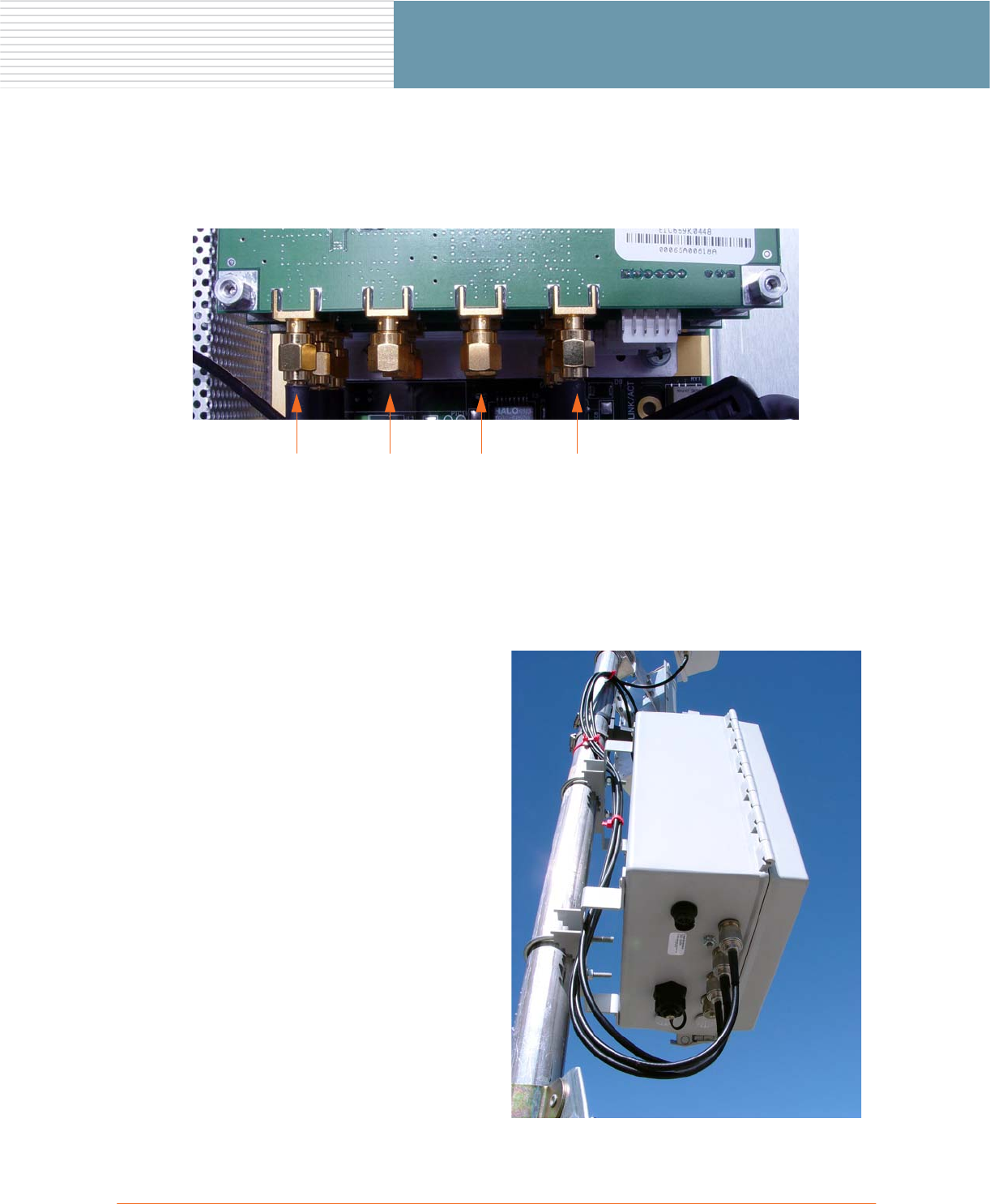
Physical Layout (Wireless Modules)
The following diagram shows the physical layout of antenna connectors on the OWS wireless modules (top
view, looking down on module when the enclosure door is open).
Routing the Antenna Cables
It is important that when you install the antenna cables they are not hanging randomly and that the cables are
secured. This section provides a sample routing scenario.
1. If mounting the OWS on a pole,
route the antenna cables through
the OWS enclosure mounting
bracket and secure with cable
ties.
Ensure that the cables are not
twisted.
2. If mounting the OWS on a wall,
the cables should be fixed to the
wall with a suitable cable clamp.
G ANT1 G ANT2 A ANT2 A ANT1
24 OWS Field Installation
OWS Field Installation
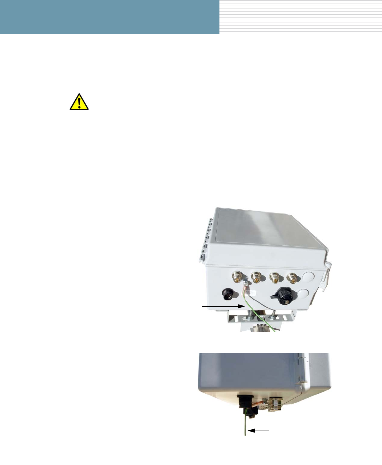
Grounding the OWS Enclosure
This section provides instructions for grounding the OWS enclosure.
Grounding Caution
Parts Required
◗Ground wire assembly (with ring terminator)—must be 18 gauge AWG wire, or greater.
Tools Required
You must ALWAYS install an external grounding wire. The ground connection must be
complete before connecting power to the OWS enclosure—a simple continuity check
between the enclosure and the ground termination point can confirm this. Grounding of
the OWS must comply with National Electrical Code (NEC) requirements, unless local
codes in your area take precedence over the NEC code.
◗3/16 inch nut wrench ◗Wire stripper (if necessary)
1. Connect the ground wire to the
ground terminal on the bottom of
the OWS enclosure.
Make sure the lock washer is in
place and that the nut is securely
fastened.
2. Connect the other end of the
ground wire to a grounding strap
attached to a grounded surface,
such as a cold water pipe (or
other suitable ground termination
point, compliant with NEC and
local standards).
On pole-mounted OWS
enclosures, if the pole (or pole
stand) is already grounded, you
may use one of these items as the
ground termination point.
Ground Wire
Connect to a
suitable ground
termination
OWS Field Installation 25
OWS Field Installation
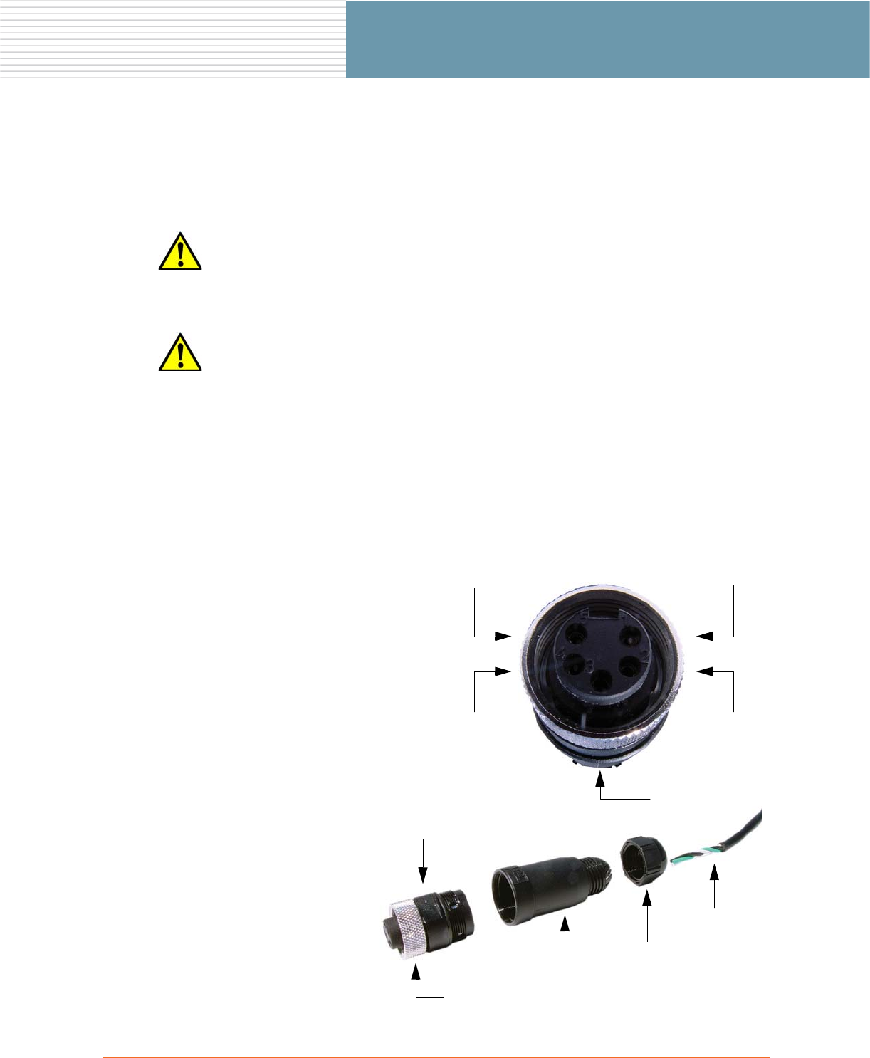
Configuring the Power Cord
This section provides instructions for configuring the power cord (not supplied) for either AC or DC operation,
and connecting the power cord to the OWS enclosure.
Electrical Power Warning
Power Cord Assembly Caution
Parts Required
◗AC or DC power cord (not supplied), cut to the desired length.
◗AC/DC plug assembly.
Tools Required
This unit must be installed by a trained professional installer only. Read the installation
instructions before you connect the wireless network device to its power source.
The power cord must be assembled by a professional installer, and the final assembly
must comply with National Electrical Code (NEC) requirements, unless local codes in
your area take precedence over the NEC code.
◗Wire stripper ◗Flat blade screwdriver
1. Review the pin connections.
◗Pin 1 – AC Neutral
◗Pin 2 – DC Positive (+)
◗Pin 3 – Ground
◗Pin 4 – DC Negative (–)
◗Pin 5 – AC Line
The example opposite shows an
AC plug assembly.
2. Assemble the plug and connect
the plug to the power cord of
your choice for the electrical
configuration you need, either
AC or DC.
The power cord must be
assembled by a professional
installer.
Plug Assembly
Shield
Collar
Power Cord
Locking Ring
Pin 1Pin 5
Pin 2Pin 4
Pin 3
26 OWS Field Installation
OWS Field Installation
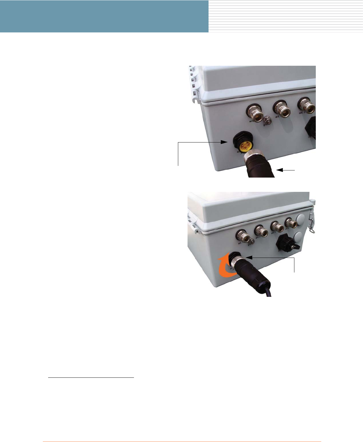
The AC1 connector you use at the
other end of the power cord
depends on the AC power source
you are connecting to. Refer to
AC Wiring Configurations on
page 27.
3. Attach the plug to the enclosure’s
power receptacle.
4. Turn the locking ring of the plug
and hand tighten to make the
connection.
5. Install an appropriate AC or DC
connector at the other end of the
power cord.
1. If using an AC power source, to comply with FCC standards for
radiated spurious EMF emissions a 30 MHz to 1 GHz ferrite core must
be attached to the AC power cord in a double-turn configuration (as
close to the OWS enclosure as possible. A suitable ferrite core for this
purpose can be obtained from Fair-Rite Products Corporation, part
number 0444164181 (round cable snap-it model).
Power Receptacle Plug
Locking Ring
OWS Field Installation 27
OWS Field Installation
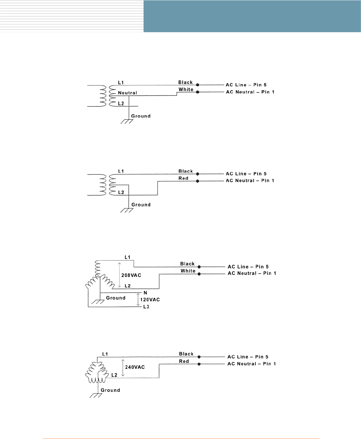
AC Wiring Configurations
The following diagrams show alternative wiring configurations for AC input power options.
120 VAC Single Phase (two wire service)
240 VAC Single Phase (two wire service)
208 VAC Three Phase (two wire service – grounded/Wye)
240 VAC Three Phase (two wire service – Delta)
28 OWS Field Installation
OWS Field Installation
Connecting the Ethernet Cable
This section provides instructions for configuring the CAT5 Ethernet cable.
Parts Required
◗Plenum-rated CAT5 Ethernet cable, cut to the desired length (not supplied).
◗RJ45 plug assembly.
Tools Required
◗Wire stripper ◗Continuity checker
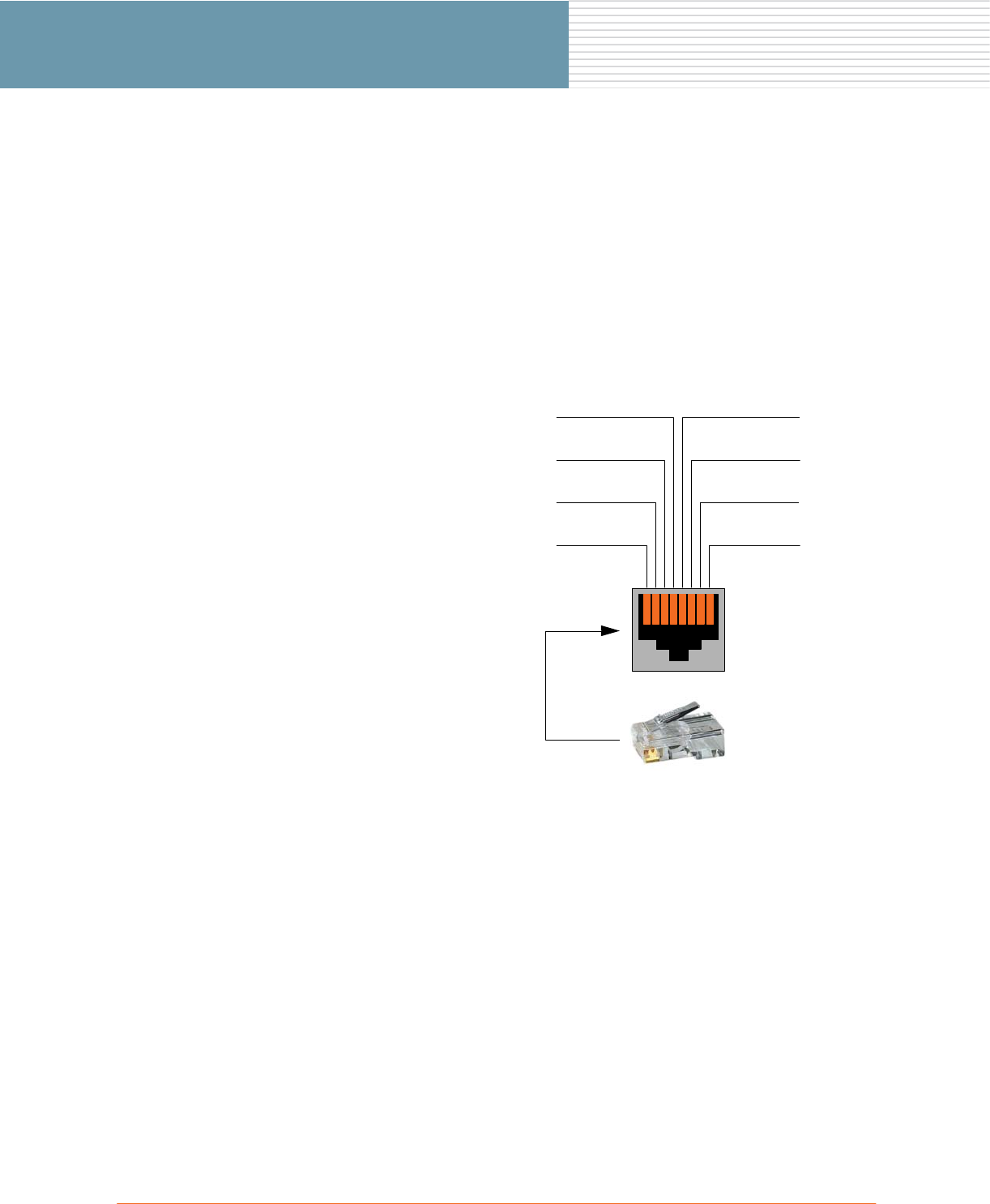
1. Review the pin connections.
◗Pin 1 – TXD+ (TX Data)
◗Pin 2 – TXD- (TX Data)
◗Pin 3 – RXD+ (RX Data)
◗Pin 4 – Not used
◗Pin 5 – Not used
◗Pin 6 – RXD- (RX Data)
◗Pin 7 – Not used
◗Pin 8 – Not used
Pin 1 Pin 8
Pin 2
Pin 3
Pin 4
Pin 7
Pin 6
Pin 5
OWS Field Installation 29
OWS Field Installation
4. Perform a continuity check on
each pin to verify that the
Ethernet cable1 has been
assembled correctly.
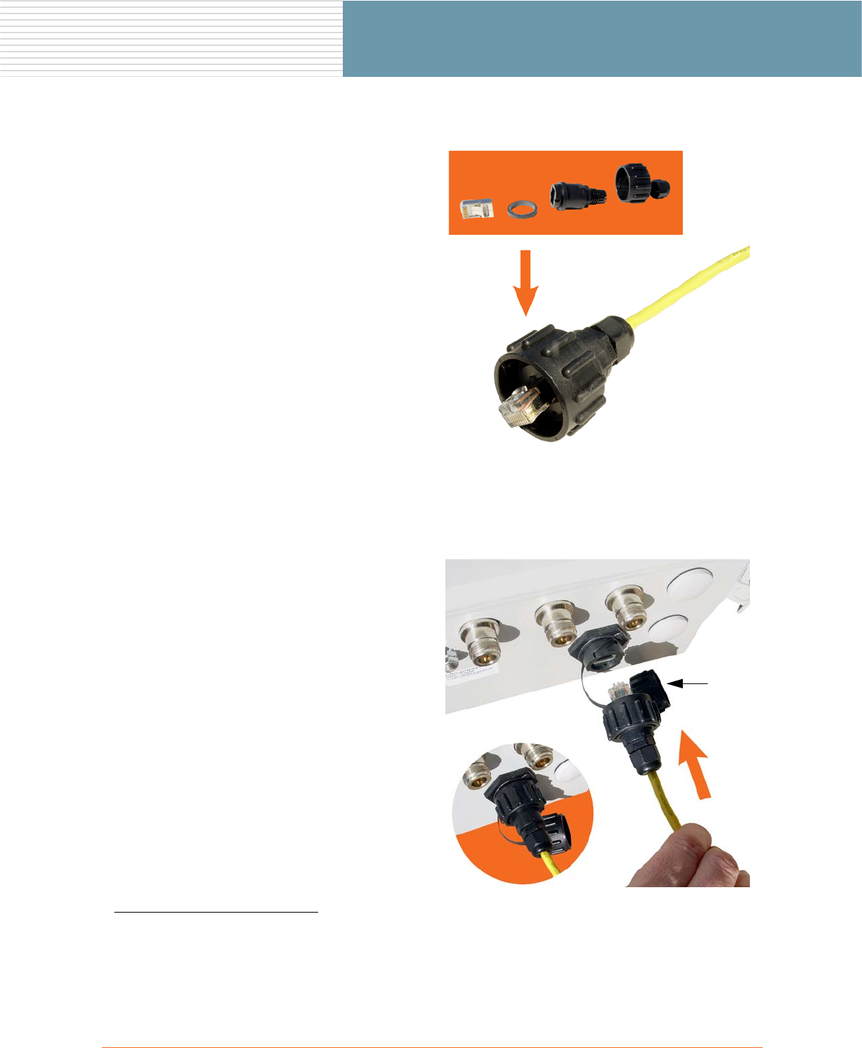
2. Assemble the RJ45 plug/cable.
◗Item 1 – Shielded RJ45 plug
◗Item 2 – Gasket seal
◗Item 3 – Plug holder
◗Item 4 – Coupling ring
◗Item 5 – Seal assembly
When assembling the plug, take
care not to lose the gasket seal
(item 2)—it must be in place
when the assembly is complete.
3. Install an RJ45 plug at the other
end of the cable.
1. To comply with FCC standards for radiated spurious EMF emissions a
30 MHz to 1 GHz ferrite core must be attached to the Ethernet cable in
a double-turn configuration. A suitable ferrite core for this purpose can
be obtained from Fair-Rite Products Corporation, part number
0444167281 (round cable snap-it model).
5. Unscrew the protective cap, then
connect the Ethernet cable to the
OWS enclosure.
Turn the coupling ring clockwise
(1/4 turn) to make the
connection.
The connection is locked when
you feel and hear a click.
12
3
45
Cap
30 OWS Field Installation
OWS Field Installation
Powering Up the OWS
This section provides instructions for powering up the OWS from both an AC and DC power source.
Powering Up from an AC Power Source
Important Note (AC Power)
1. Verify that the AC service voltage is 120 VAC to 240 VAC.
2. Check that the power is turned OFF at the designated circuits.
3. If necessary, install 1/2 inch liquid-tight conduit from the power source to within 3 feet of the OWS,
then connect the conduit to a junction box. The conduit and junction box must be IEEE/ANSI
compliant and suitable for outdoor use.
4. Connect the OWS power cord to the AC supply.
5. Close the enclosure’s door (the OWS door interlock will actuate).
6. Turn ON the AC supply.
Powering Up from a DC Power Source
Important Note (DC Power)
1. Verify that the DC service voltage is 12 VDC to 24 VDC.
2. Check that the power is turned OFF at the designated circuits.
3. If necessary, install 1/2 inch liquid-tight conduit from the power source to within 3 feet of the OWS,
then connect the conduit to a junction box. The conduit and junction box must be IEEE/ANSI
compliant and suitable for outdoor use.
4. Connect the OWS power cord to the DC supply.
5. Close the enclosure’s door (the OWS door interlock will actuate).
6. Turn ON the DC supply.
AC input: 100 – 240 VAC (50/60 Hz) at 1.0 Amp maximum, supplied by a separate
branch circuit with 2 Amp over-current protection (2 Amp circuit breaker).
The OWS must always be grounded before applying power to the unit—see Grounding
the OWS Enclosure on page 24.
DC input: 12 – 24 VDC at 9.0 Amp maximum, supplied by an external separate 250 VA
power-limited (or less) and isolated DC source with 15 Amp over-current protection (15
Amp circuit breaker).
The OWS must always be grounded before applying power to the unit—see Grounding
the OWS Enclosure on page 24.

OWS Field Installation 31
OWS Field Installation
OWS Product Specifications
WIRELESS
◗Wireless Standards: IEEE 802.11a/g
◗Frequency Bands:
802.11a
- 5.725 - 5.825 GHz
802.11g
- 2.4 - 2.4835 GHz (Americas, FCC)
Public Safety
- 4.940 - 4.990 GHz
◗Data Rates (Mbps):
- 6, 9, 12, 18, 24, 36, 48, 54 (802.11a/g)
- 12, 18, 24, 36, 48, 72, 96
◗Wireless Medium:
802.11a – OFDM, 802.11g – DSSS
◗Modulation:
- 802.11a: BPSK, QPSK, 16 QAM, 64 QAM
- 802.11g: DBPSK, DQPSK, CCK
◗Operating Channels:
802.11a
- 5 (Americas, FCC)
802.11g
- 11 (Americas, FCC)
Public Safety (4.9 GHz)
- 2 (Americas, FCC)
◗Transmit Power:
Configuration dependent—contact Strix
◗Receiver Sensitivity:
Configuration dependent—contact Strix
◗LO (crystal) Frequency Stability:
+/-10PPM within normal op. range of 0° to 55°C
ELECTRICAL
◗Power Input:
Auto-sensing 120/240 VAC, 50/60 Hz, single
phase, with ANSI/IEEE C62.41 category C3
integrated branch circuit protection
◗AC Power Consumption:
25W typical, 90W maximum
◗DC Input:
12/24V, 9A maximum
PROTECTION CIRCUITS
◗Antenna Lightning Protection (optional):
< 9μJ for 6kV/3kA @ 8/20μs waveform
◗Electrical Protection:
ANSI/IEEE C62.41, UL 1449 2nd edition; 10kA @
8/20 μs waveform, 36kA per phase; L-L, L-N, L-PE
◗Data Protection:
EN61000-4-2 Level 4 ESD Immunity
EN61000-4-5 Level 4 AC Surge Immunity
EN61000-4-4 Level 4 Elect. Fast Transient Burst
Immun.
EN61000-4-3 EMV Field Immunity
ENVIRONMENTAL
◗Operating Temperature: -40°C to +55°C
◗Storage Temperature: -55°C to +85°C
◗Humidity: 10% to 90% non-condensing
◗Weather Rating: IP67 weather tight
◗Wind Survivability: <165 mph
◗Wind Loading (165 mph): <1024 newtons
◗Salt/Fog/Rust Resistance: Mil-STD-810F 509.4
◗Shock & Vibration:
ESTI 300-192-4 spec T41.E
Class 4M3 and Mil-STD-810
◗Transportation: ISTA 2A and Mil-STD-810
PHYSICAL
◗Dimensions:
3600 Series: 14” high x 12” wide x 8” deep (without
accessories)
2400 Series: 12” high x 10” wide x 6” deep (without
accessories)
◗Weight:
3600 Series: 16.5lbs (7.48 Kg)
2400 Series: 14.5lbs (6.58 Kg)
◗NEMA 4 rated for outdoor enclosures
SECURITY
◗Authentication:
802.1x support, including RADIUS client, EAP-MD5,
EAP-TLS, and PEAP-TTLS, WPA
◗Encryption:
IEEE 802.11i (WPA) with AES, and WEP
REMOTE MANAGEMENT
◗Web, CLI and SNMP interfaces
◗Supports BOOTP, DHCP, Telnet, SSH, HTTP, HTTPs, and
FTP
◗SNMP: MIB II, 802.11 MIB, and Strix private MIBs
APPROVALS
◗FCC CFR47 Part 15, Class B
◗FCC, Part 90, Section Y
◗Industry Canada RSS210
◗EN60950 cTUVus Listed I.T.E
◗UL 579/IEC 60529 IP67, rated for outdoor use
◗UL 1449 2nd edition / IEC 60664-1
◗CAN/CSA-C22.2 60950-00
◗VCCI Class B
WARRANTY
◗One year parts and labor
32 OWS Field Installation
OWS Field Installation
Appendix I: Setting the Output Power
Use the following procedure to set the output (transmit) power for the chosen antenna:
1. Establish a Telnet connection with the selected wireless module (radio).
2. Log in to the radio.
3. Type the command get power.
The system displays the current power settings for the selected radio.
If the radio is set to the desired power setting, no further action is required and you can log out,
otherwise go to Step 4. The following list shows the available power settings:
◗Full – sets the maximum (normal) transmit power. This is the default setting.
◗Half – sets the transmit power to a fractional half of the full power.
◗Quarter – sets the transmit power to a fractional quarter of the full power.
◗Eighth – sets the transmit power to a fractional eighth of the full power.
◗Minimum – sets the transmit power to its minimum.
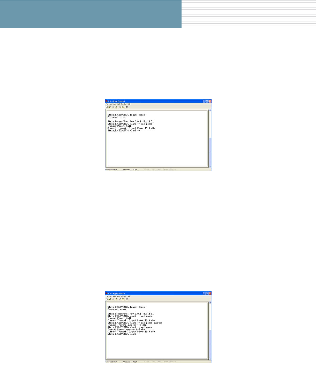
4. To set the power output for the selected radio, type the command set power and append the desired
setting to the command. For example, to set the output power to minimum, type set power min. Or,
to set the output power to one quarter, type set power quarter.
When the command is entered, the system displays the new power setting automatically. However, if
you need to verify the output power setting for any radio, use the command get power. The following
graphic shows the output power for a radio being changed from full to one quarter.
OWS Field Installation 33
OWS Field Installation
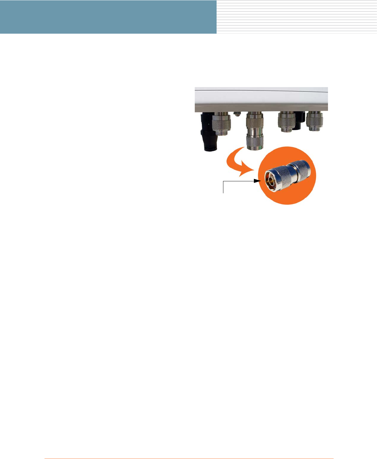
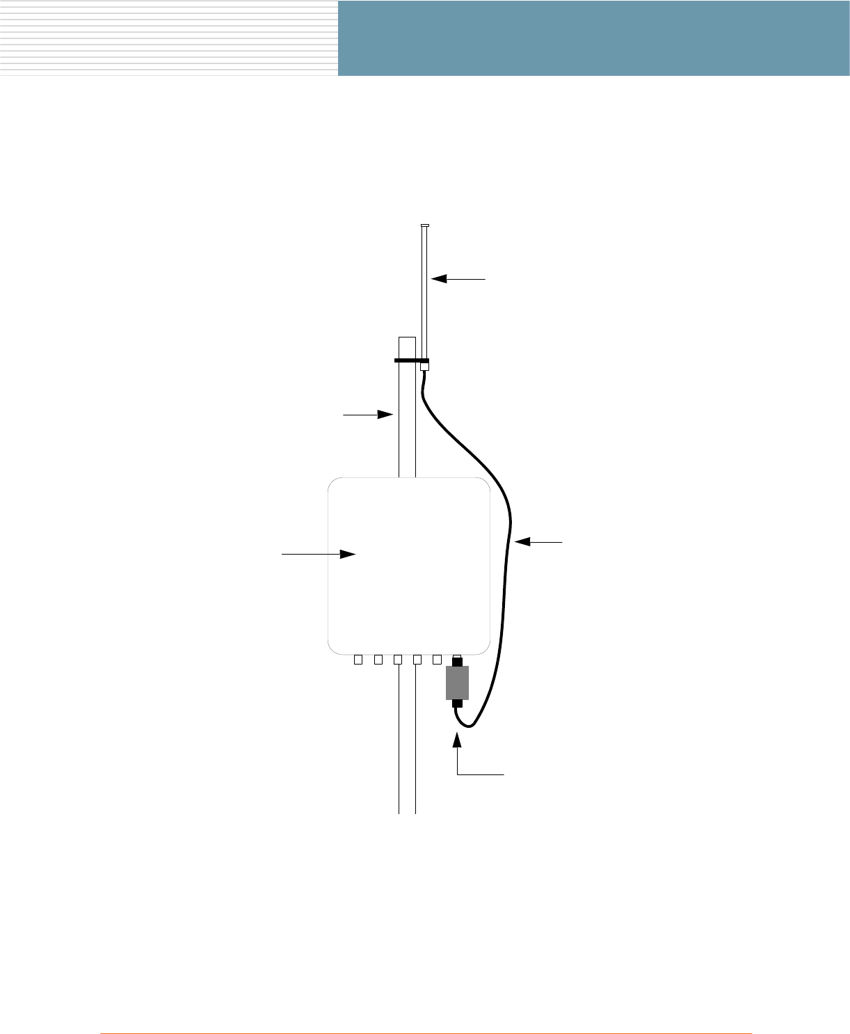
Appendix II: Installing the Band Pass Filter
The band pass filter must be installed as close to the OWS enclosure as possible. The following graphic shows
the filter installed on the OWS at its preferred location (connected directly to the antenna connector on the
enclosure).
Antenna
Antenna Cable
OWS Enclosure
Pole
Band Pass Filter

34 OWS Field Installation
OWS Field Installation

OWS Field Installation 35
OWS Field Installation
Index
A
AC power 30
adapter 12,13
airplanes
use in 1
antenna
directional 14
antenna adapter 13
antennas
cable routing 23
directional 14
installing 8
omni 12,19
placement 2
routing cables 23
sectored 16
type 2
B
band pass filter
installing 33
building codes 2
building materials 2
C
CAT5 28
CAT5 cable 28
contact information i
continuity check 29
copyright notice i,ii
coupling 29
D
data rates 2
DC power 30
directional antenna 8,14
adjusting 15
E
enclosure 3
enclsure
grounding 24
environmental limits 1
Ethernet cable 28
European Community (EC) conformity ii
explosive device proximity iii
F
FAA 1
FCC notice ii
Federal Aviation Administration 1
filter 33
G
gasket seal 29
ground termination 24
grounding 24
H
hazardous locations 1
hospitals
use in 1
I
Industry Canada notice ii
L
limited warranty v
local guidelines 2
M
maximum power settings 9
mounting 3
brackets 3
on a vertical pole 3
on a wall 7
N
NEC code 2,24,28
non-modification statement iii
notices ii
European Community (EC) ii
FCC ii
Industry Canada ii
VCCI ii
O
obstructions 2
omni antenna 8,12,19
output power
setting 32
over-current protection 30
OWS 2400 1
OWS 3600 1
OWS enclosure 3
grounding 24
P
physical environment 2
planning the installation 2
planning your installation 2
pole 3

36 OWS Field Installation
OWS Field Installation
power settings 9
power source 2
powering up 30
product specifications 31
public safety 11
R
RF exposure iii
RJ45 plug assembly 29
S
safety information 1
safety warnings iii
sectored antenna 16
setting the transmit power 32
site survey 2
site surveys 2
solar shield iv
specifications 31
straps 3,6
Strix contact information i
survey 2
T
theory of operation 1
transmit power 32
U
u-bolts 3,4
V
VCCI notice ii
vertical mounting brackets 3
vertical pole 3
W
warnings iii
antenna placement iv
electrical power iii
general safety iii
grounding the unit iv
lightning activity iii
warranty v