Strix Systems OWS2420-90 802.11 a/b/g 4.9 GHz Wireless, Mesh Access Point User Manual accessone userguide
Strix Systems, Inc. 802.11 a/b/g 4.9 GHz Wireless, Mesh Access Point accessone userguide
Contents
User Manual Part 4 of 5
Access / One® Network
Managing the Network 123
5
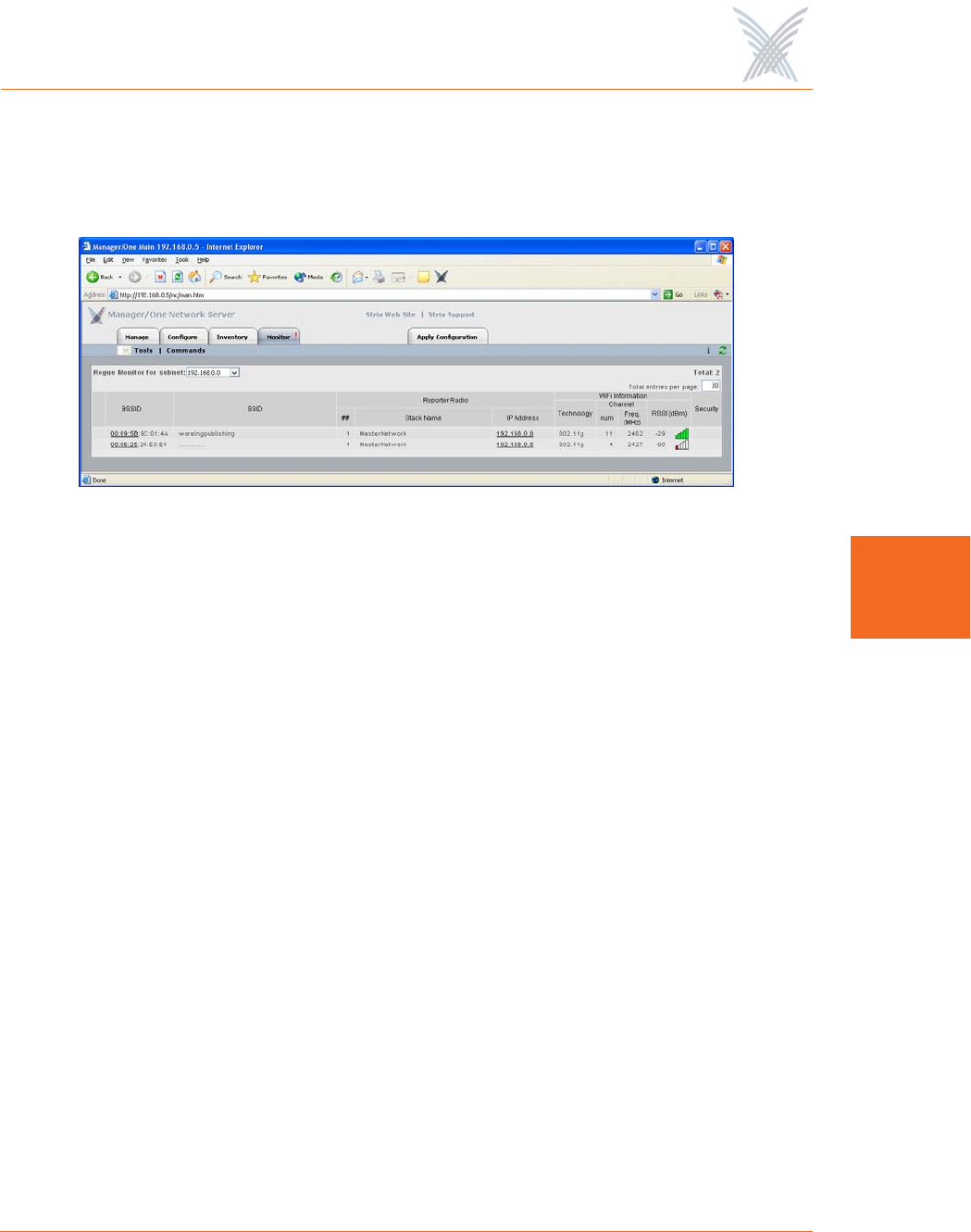
Rogue Monitor
The Rogue Monitor provides a snapshot in table form of all rogue devices detected
on a selected subnet.
Figure 99. Rogue Monitor
Although the displayed data is different, the organization of tables in all monitors is
the same. For information about how to define the sort criteria within the Rogue
Monitor table, see Figure 94. And similar to the Network Connect Monitor and the
Wireless Client Query Monitor, the Rogue Monitor also includes the information
button (i) in the top right corner of the window. Clicking on this button generates
the RSSI Legend pop-up window (see Figure 96).
Scan
Use this command if you want to initiate an active scan for rogue devices. Active
scans can take up to one minute to complete and network traffic will be disrupted
during the scanning process. Results from the scan are reported in the Rogue
Monitor table (see Figure 99).
Ignore All
Use this command to refresh the Rogue Monitor table with all detected rogue
devices ignored. All ignored devices are grayed out.
Include All
Use this command to refresh the Rogue Monitor table with all detected rogue
devices included.
Access / One® Network
124 Managing the Network
5
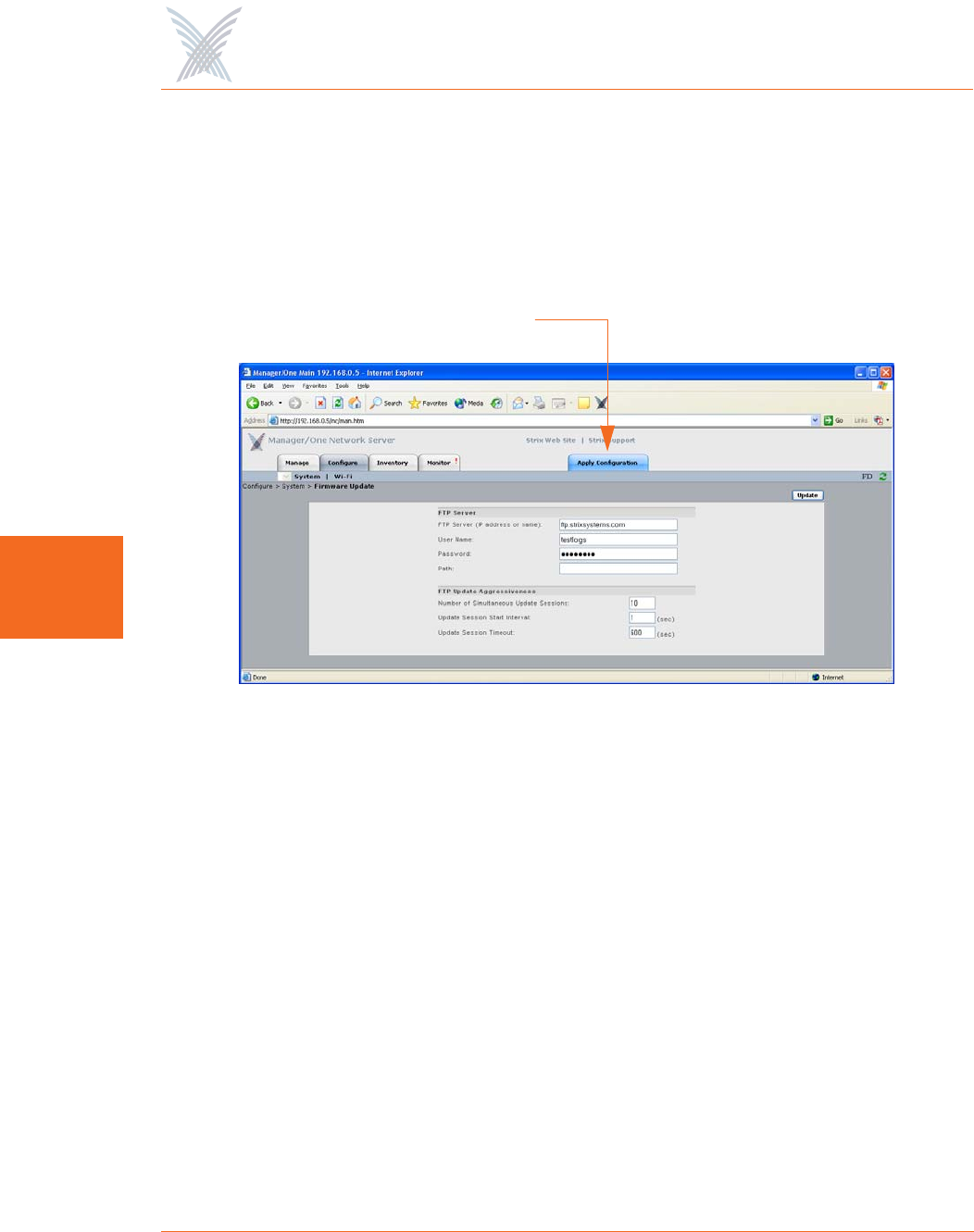
The Apply Configuration Function
This function is used to apply any configuration changes that have been made at
either the network or subnet level. When BLUE, click on this tab to propagate and
apply your changes to all nodes and wireless modules within your Access/One
Network or a specific subnet.
Figure 100. Apply Configuration
Important Notes About Apply Configuration
The following notes are important considerations when using the Apply
Configuration function.
For changes to be applied at the network or subnet level, you must
reboot the network after clicking on the Apply Configuration tab,
otherwise your changes will not be implemented.
The Apply Configuration function is not available when configuring
individual modules, because configuration changes at the module level
are applied automatically when you click on the Update button.
Apply Configuration

Access / One® Network
Managing the Network 125
5
Enabling Communication Between Remote Subnets
Your Access/One Network can be configured to enable communication between
network servers on remote subnets, allowing you to manage subnets from any
network server on the network, regardless of its location. For example, remote
subnets in New York and Los Angeles can be configured and managed from the
same Manager/One interface.
Example
Los Angeles and New York each have their own network:
◗Los Angeles (LA): 172.20.0.0
◗New York (NY): 192.152.1.0)
You want both networks to be managed by the same Manager/One interface, and
you can assume that a network server in Los Angeles (172.20.0.50) is the primary
server for the Access/One Network.
See also, “Starting a New Network” on page 32.
It is recommended that you complete all of your configuration changes
before using the Apply Configuration command to propagate your
changes throughout the network. Once the Apply Configuration
command has been initiated, you cannot make any further changes
until the command cycle has been completed.
It is strongly recommended that customers use an NTP (Network Time
Protocol) server to synchronize Access/One Network to one clock. This
will ensure that the system's internal Syslog time-stamping process is
maintained correctly. See also, “Enabling Windows 2000 Servers for
NTP Requests” on page 33. Without an NTP server (no universal clock),
each network server will use its own internal clock and stamp times
accordingly.

Access / One® Network
126 Managing the Network
5
Procedure
Configure a single remote network server for each subnet (NY: 192.162.1.22) on the
LA server. Within a few minutes, Strix’s mesh topology feature will cause all of the
remote subnets to automatically appear in each network server. Your Access/One
Network is now manageable from any of the network servers in the network.
Removing the NS to NS Feature
To remove the NS to NS communication feature, delete all of the remote server
entries on the LA server. When done, click on the Update button, then click on the
Apply Configuration tab and reboot the network (to apply your changes).
Managing Remote Subnets from Manager/One
In most cases, configuration of your Access/One Network will apply to all subnets to
maintain an homogeneous network. There are a few commands which can only be
applied at the subnet level. The following commands apply to the network level
only (regardless of what view is currently displayed):
◗Load Firmware on Network
◗The Apply Configuration Function
The following commands apply at the network or subnet level (depending on what
view is currently displayed):
◗Reboot Network (network only)
◗Reboot... (subnet / network)
The following commands are applicable only at the subnet level:
◗Update Network Membership
◗Update Node Names
Access / One® Network
Managing Subnets and Nodes 127
6
Managing Subnets and Nodes
This chapter covers management tasks at the subnet and node levels—you can only
manage a subnet or node (you cannot configure subnets or nodes independent of
the network). If you are managing your Access/One Network at the network level, or
managing an individual module (for example, a wireless module or network server),
go to the relevant chapter:
◗“Managing the Network” on page 65.
◗“Managing Modules” on page 133.
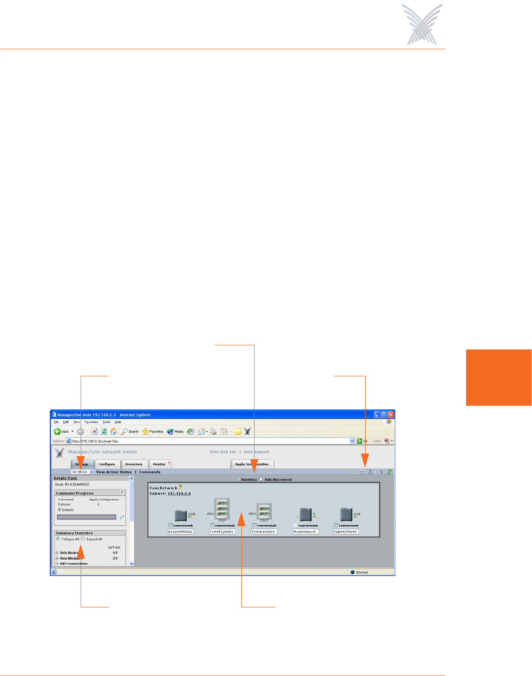
The following graphic shows the subnet (subcloud) view in Manager/One’s main
window. The subnet view displays all nodes within the selected subnet and provides
interface features that are not available at the network level. All tasks in this chapter
are performed at the subnet or node levels.
Figure 101. Subnet (Subcloud) View
IP Address
Details Pane Subnet (Subcloud)
Views
Discovery Options

Access / One® Network
128 Managing Subnets and Nodes
6
Interface Features in the Subnet View
The interface features that are unique to the subnet view have already been
discussed in Chapter 4, The Manager/One Interface. They are listed here for your
convenience, and include:
◗“A Choice of Layouts” on page 45.
◗“The Details Pane” on page 56.
◗“Inventory or Auto Discovered” on page 63.
The Manage Function
To avoid repetition, this section only addresses the management commands at the
subnet and node levels that are different from the equivalent commands at the
network level, or management commands that are unique to the subnet and node
levels. Therefore, the section headings included here are limited to the following
commands in the Manage function only:
◗Commands (at the Subnet Level)
•Load Firmware...
–Subnet
–Network
•Reboot...
–Subnet
–Network
◗Commands (at the Node Level)
•Update Node Names
•Update Network Membership
All other commands that are available at the subnet level but not listed here can be
found in Chapter 5, Managing the Network. You can also find them in the Table of
Contents and the Index.
Access / One® Network
Managing Subnets and Nodes 129
6
Commands (at the Subnet Level)
Load Firmware...
This command allows you to load a new firmware image to each of the modules
contained in all network nodes within your Access/One Network or to a specific
subnet. However, before you can load a new image, your FTP server parameters
must be established correctly to let Manager/One know where to locate the new
image (BIN) file.
To establish the correct FTP parameters and load new firmware at the network or
subnet levels, go to “Updating the Firmware” on page 35.
Subnet
Choose this option to load new firmware to all devices within the selected subnet.
Network
Choose this option to load new firmware to all subnets and devices within your
entire Access/One Network.
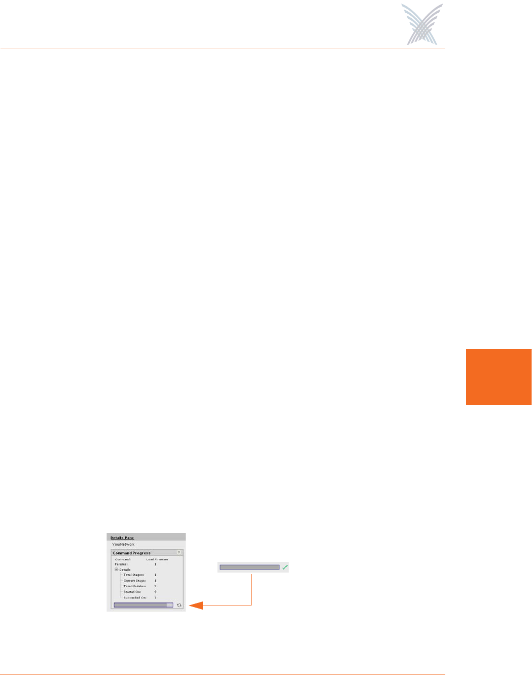
Reboot...
This command reboots each module in all nodes within your Access/One Network
or a selected subnet. Rebooting is required when configuration changes are made or
a new firmware image is loaded. To monitor the progress of the reboot operation,
the network server generates the request in stages. When each module reports
receiving the reboot command and successfully reboots, the network server
performs a final self-reboot. You can monitor reboot progress reports with the View
Action Status command or from the Command Progress pane.
Figure 102. Command Progress Pane
Success
Access / One® Network
130 Managing Subnets and Nodes
6
Whenever you initiate the Reboot... command, the system warns you that this action
will affect multiple devices on the network (or subnet) and asks you to confirm the
request. If you want to proceed, click on the OK button to initiate the reboot
process, otherwise click on the Cancel button to abort the command.
See also, “Important Note About Rebooting” on page 4.
Subnet
Choose this option to reboot the selected subnet.
Network
Choose this option to reboot your entire Access/One Network.
Commands (at the Node Level)
Update Node Names
The ability to assign names to your nodes is provided as a convenience to users who
want their nodes to have meaningful names (for example, based on the node’s
location).
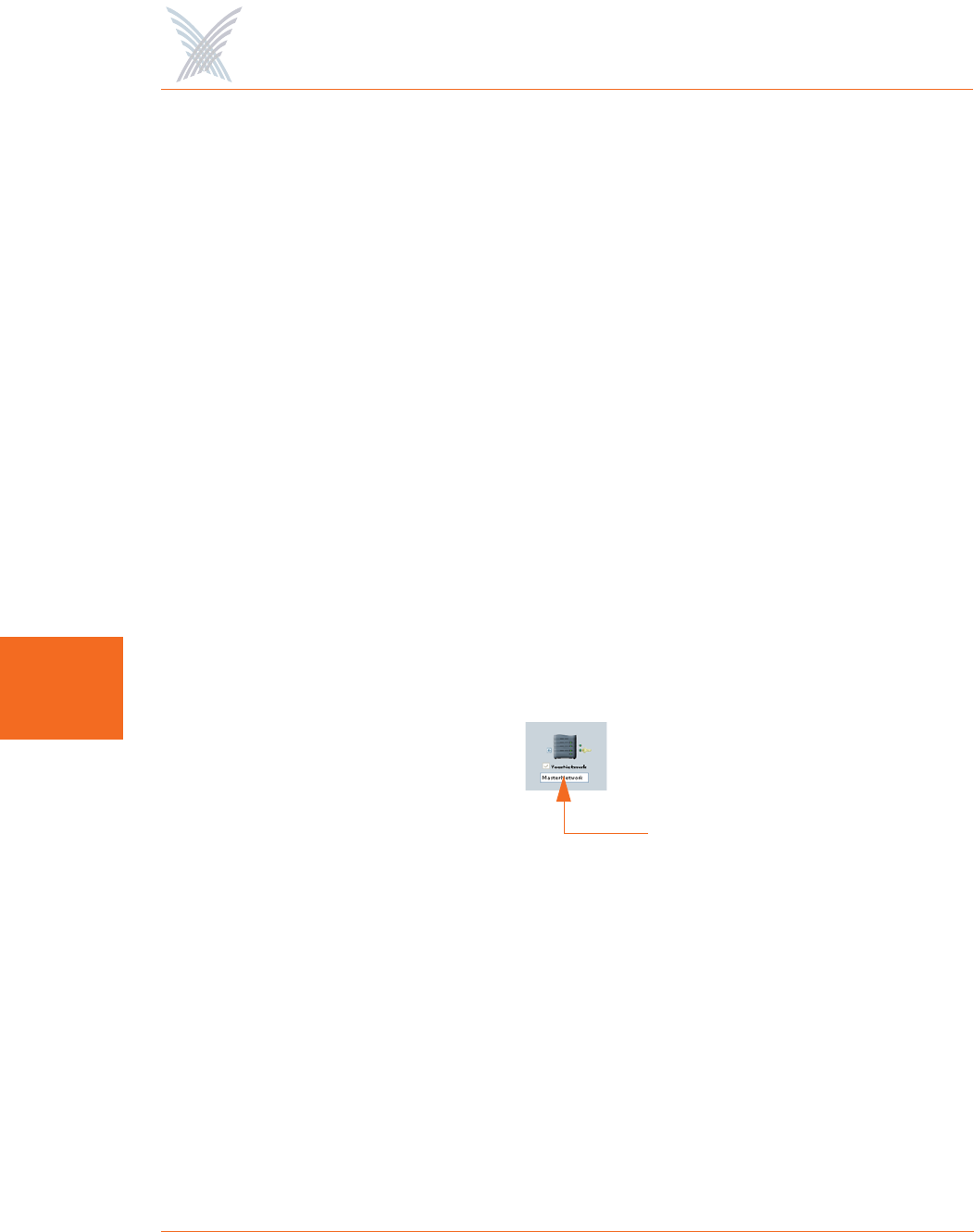
Figure 103. Node Name (Flat View)
In Manager/One, the node name appears below the node in an editable text field.
You can assign any name with up to 15 alphanumeric characters, but the name must
be unique within your Access/One Network. If you attempt to enter a name that
already exists (a duplicate name), Manager/One will prompt you for a new name.
Name changes do not require a reboot, but may take between 10 and 15 seconds
before the change is reported. Refresh your browser window frequently to ensure
that the latest information is displayed.
Node Name
Access / One® Network
Managing Subnets and Nodes 131
6
To change a name, simply enter a new name in the text field below the node and
select the Update Node Names command. When prompted, click on the OK button
to apply your change.
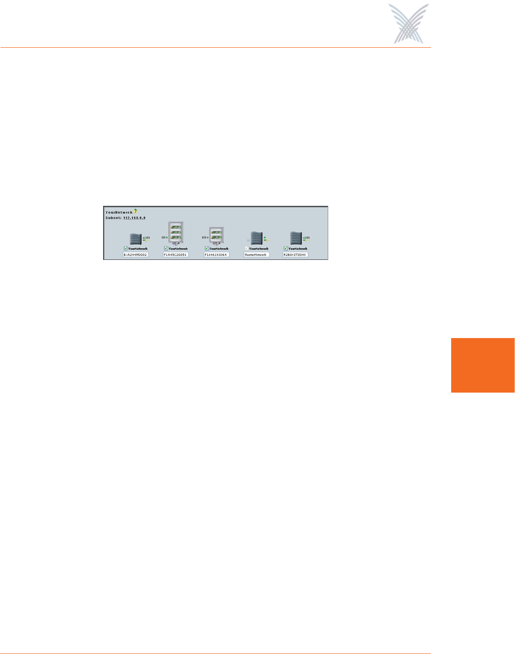
Update Network Membership
The subnet (subcloud) displays all of the nodes residing in the network. Nodes
already assigned to the network (members) are GREY in color and the check box
below the node is checked.
Figure 104. Network Membership
You can add or remove nodes from the network by checking or unchecking the
check box below the node, then selecting the Update Network Membership
command. This action forces a reboot of the nodes which have changed their
membership status (nodes not admitted to a network, other than the default, will not
bridge user traffic).
IWS nodes that are BLUE do not have a check mark in the check box,
and although they are currently not assigned to the network, they can
be admitted (become members). All nodes admitted to the network will
be rebooted. Nodes that are RED also do not have a check mark in the
check box, but these nodes are unavailable and cannot be assigned to
the network.

Access / One® Network
132 Managing Subnets and Nodes
6
Use this Space for Your Notes

Access / One® Network
Managing Modules 133
7
Managing Modules
This chapter covers management and configuration tasks at the individual module
level (for example, wireless modules or network servers). It is generally sufficient to
configure your Access/One Network as a whole without configuring specific
modules. If you are managing the network, a subnet or node, go to the relevant
chapter:
◗“Managing the Network” on page 65.
◗“Managing Subnets and Nodes” on page 127.
When a module is configured, the module’s manually configured parameters will
always override the global network parameters that are configured or defaulted at
the network level. It is presumed that if a module is manually configured, then the
module’s values take precedence over global network values.
Manger/One at the Module Level
When you drill down to the module level in Manager/One you will notice that the
function tabs and available commands change, depending on what type of module
you have selected (wireless module or network server). For example, If you are
logged in to a wireless module, Manager/One presents you with a Rogue Devices
function and Wi-Fi commands under the Configure function—none of these options
being available if you are logged in to a network server (they are not required for
network servers).
Also, and regardless of what type of module you are logged in to, the Apply
Configuration tab is not available at the module level. The Apply Configuration tab
is only applicable at the network level where you need to propagate your
configuration changes across the entire network.
To avoid repetition, this chapter only addresses the commands at the module level
that are different from the equivalent commands at the network level, or commands
that are unique to individual modules. For your convenience, cross-references are
included that will take you to the corresponding commands at the network level.

Access / One® Network
134 Managing Modules
7
When you initiate a command at the module level, the configuration pages that are
displayed contain the configuration settings that are currently applied to the selected
module only (not the network or any other module).
The Manage Function
This function provides you with the tools you need to manage individual modules
and includes the following commands:
◗Actions
•Factory Defaults
•Load Firmware/Configuration
•Page Device
•Reboot
In most cases, the only difference between a configuration window
generated at the network level and the same window generated at the
module level is the inclusion of pre-configured module data (if any) in
the fields contained within the window.
Access / One® Network
Managing Modules 135
7
Actions
This area of Manger/One applies to all modules (wireless modules and network
servers) and contains commands that allow you to establish factory default settings,
load firmware and/or configuration files, and page or reboot the module.
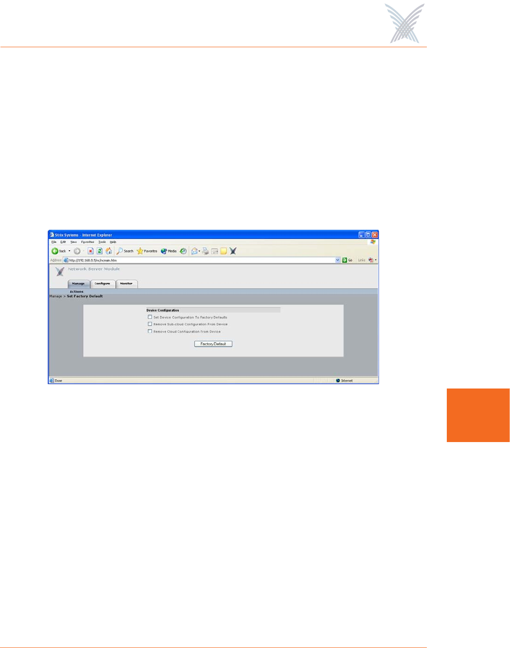
Factory Defaults
This command allows you to set the module’s configuration settings to their factory
default state or remove the subnet and/or network configuration parameters from the
module.
Figure 105. Device Configuration Window
Make your selection(s) from the available options:
◗Set Device Configuration To Factory Defaults
Enable this option to reset the module to its factory default state.
◗Remove Sub-cloud Configuration From Device
Enable this option to remove any configuration settings that were applied to
the module at the subnet level.
◗Remove Cloud Configuration From Device
Enable this option to remove any configuration settings that were applied to
the module at the network level.
After making your selections, click on the Factory Default button to apply your
changes, then click on the Reboot button to reboot the module.
Access / One® Network
136 Managing Modules
7
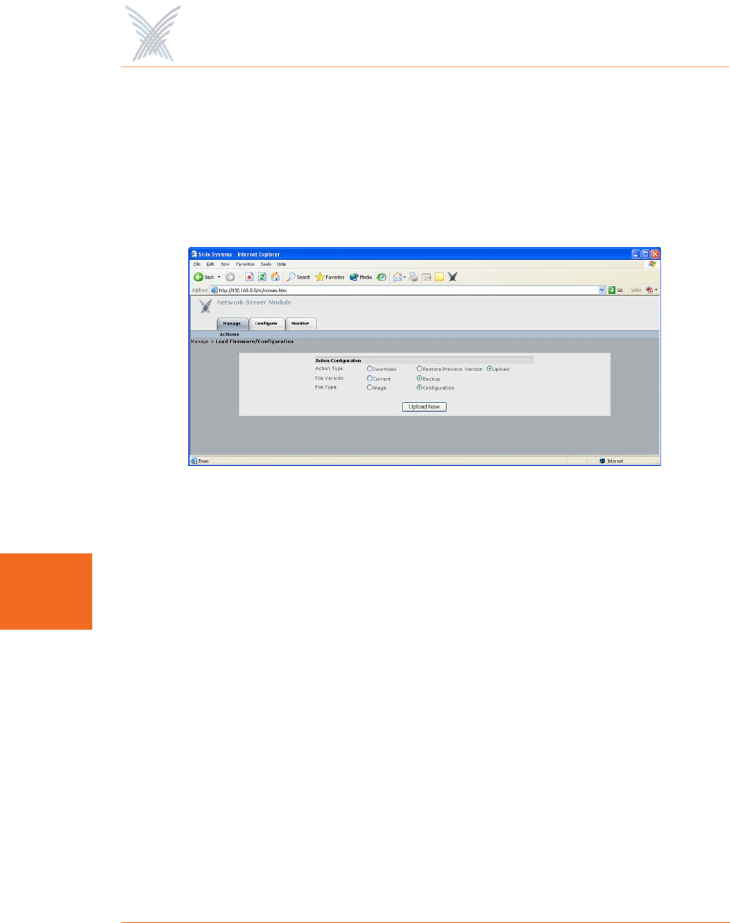
Load Firmware/Configuration
This command allows you to load a new firmware image and /or configuration file
to the module, restore a previous version (or backup file), or upload a backup
firmware image and /or configuration file. The following graphic shows the Load
Firmware/Configuration window with its options set for uploading a backup
configuration file.
Figure 106. Loading a New Firmware Image or Configuration File
Go to “Firmware Updates” on page 145 and establish the FTP server parameters to
inform Manager/One where to locate the new firmware image or configuration file,
and which file to use. The following options are available with this command:
◗Action Type
Choose Download, Restore Previous Version, or Upload.
◗File Version
Define the file version, either Current or Backup (only available if you are
uploading a file).
◗File Type
Define the file type, either Image or Configuration.
Click on the Download Now,Restore Now, or Upload Now button (depending on
which action you defined) to execute the command, then click on the Reboot
button to reboot the module.
Access / One® Network
Managing Modules 137
7
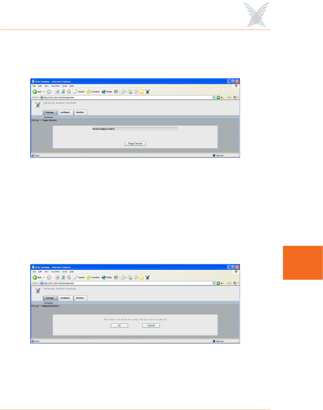
Page Device
This command allows you to page the module (device) that you are currently logged
in to.
Figure 107. Paging a Device
To page the module, simply click on the Page Device button. When an IWS (Indoor
Wireless System) module is paged, the module’s LED blinks between GREEN and
RED, indicating that communication with the module is successful. The module will
be paged until you click on the Disable Page button.
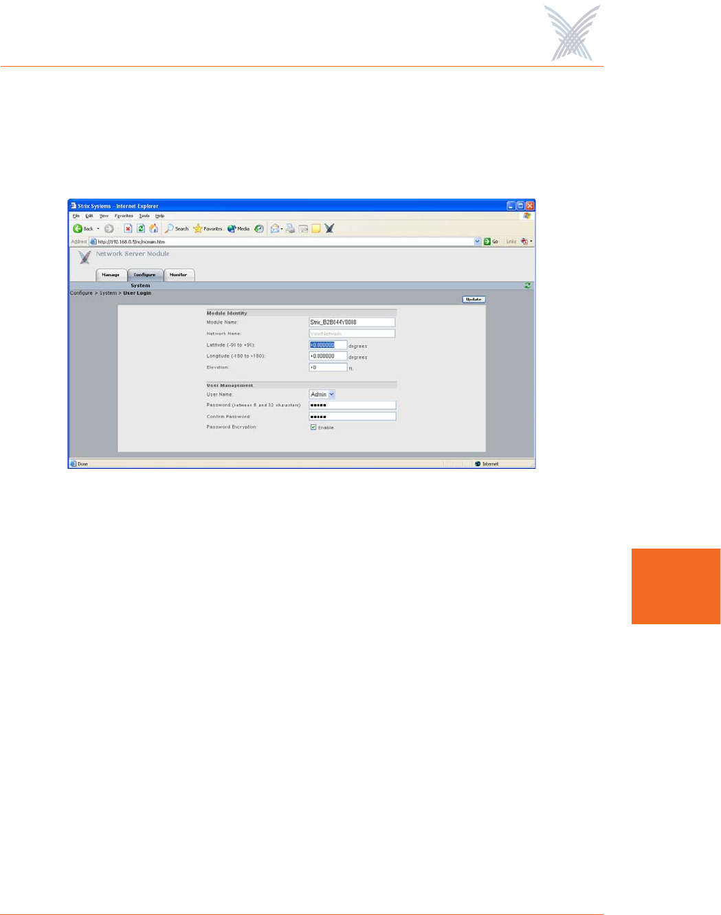
Reboot
This command allows you to reboot the module.
Figure 108. Rebooting a Module
Click on the Reboot button to reboot the module, or click on the Cancel button to
cancel the request.

Access / One® Network
138 Managing Modules
7
The Configure Function
This function provides you with the tools you need to configure individual modules
and includes the following commands:
◗System
•User Login
•Network Management
–General
–SNMP
–Trusted IP Addresses
•TCP/IP Settings
•Priority/One - Class of Service
•Radius Accounting
•Syslog
•Date and Time
•Operating Environment
•Firmware Updates
◗Wi-Fi (Wireless Modules Only)
•Radio Parameters
•Client Connect
•Network Connect
•Rogue Scan
System
This area of Manger/One applies to all modules (wireless modules and network
servers) and contains commands that allow you to configure the module’s system-
level parameters. Any configuration parameters that you apply to the module will
supersede the equivalent system-level parameters that were applied at the network
level and propagated to the module from the Apply Configuration tab.
Access / One® Network
Managing Modules 139
7
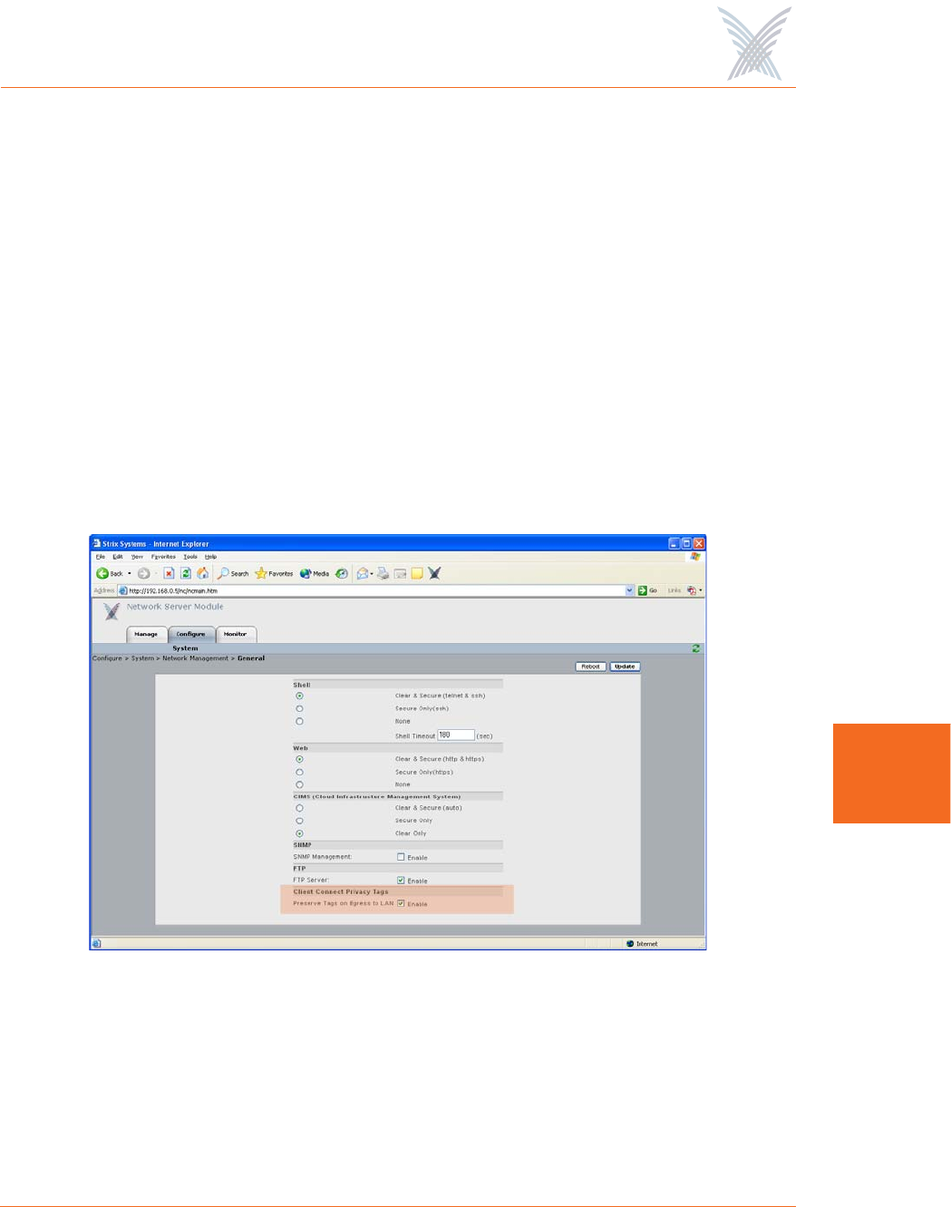
User Login
This command allows you to establish the identity of this module, define its physical
location within the environment based on latitude, longitude and elevation, and set
up the module’s login parameters (username and password).
Figure 109. Module Identity and User Management (Login) Parameters
The following options are available with this command:
◗Module Name
Edit the existing name or enter a new name for this module. If no name is
defined for the module, the system automatically sets the module’s factory
default serial number as the name.
◗Network Name
This field (not editable) shows the name of the network that this module is
associated with. If you need to change the network association for this
module, go to “Update Network Membership” on page 131.
◗Latitude
This field allows you to define the specific latitude for where this module is
located (more relevant to OWS modules where physical location and
environment can be extreme). This setting must be within the range of -90
degrees/minutes to +90 degrees/minutes. The default is +0.000000.

Access / One® Network
140 Managing Modules
7
◗Longitude
This field allows you to define the specific longitude for where this module is
located (more relevant to OWS modules where physical location and
environment can be extreme). This setting must be within the range of -180
degrees/minutes to +180 degrees/minutes. The default is +0.000000.
◗Elevation
This field allows you to define the specific elevation (in feet) for where this
module is located (more relevant to OWS modules where physical location
and environment can be extreme). The default is +0 feet (sea level).
◗User name
Select a user name from the pull-down list (Admin or Guest). Any changes
you make to the password in the following field will affect logins to this
module for the selected user name only.
◗Password
Enter a password (between 5 and 32 characters). All passwords are case-
sensitive. Any change you make to the password will affect logins for this
module only.
◗Confirm Password
Re-enter the password to confirm that you typed it correctly.
◗Password Encryption
Check this box if you want Access/One Network to encrypt your password for
additional security.
When finished, click on the Update button to update this page and apply your
changes, then click on the Reboot button to reboot the module. If necessary, you
can click on the Refresh button in the toolbar to reset all parameters on this page to
their original values.
The default for the user name and the password for all modules
within your Access/One Network is Admin (with a capitalized A)
for both. We strongly recommend that you change the default
password immediately after your initial login.
Access / One® Network
Managing Modules 141
7
Network Management
This command generates three sub-commands (General, SNMP, and Trusted IP
Addresses) that allow you to define parameters for how the module is managed
within your Access/One Network. For the most part, these commands are the same
as their corresponding commands at the network level (with some minor exceptions
that are documented here).
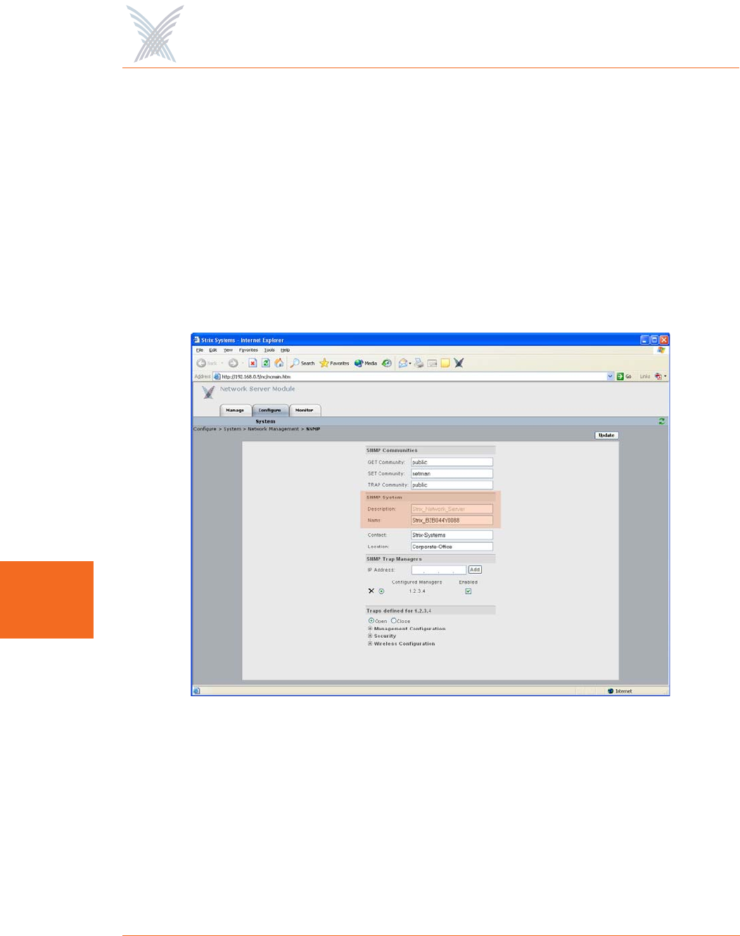
General
Unless you are logged in to a network server, this command is the same as its
corresponding command at the network level. In this case, go to “General” on
page 73 to configure all options under this command. If you are logged in to a
network server, the window generated by this command includes an additional
option called Client Connect Privacy Tags.
Figure 110. Client Connect Privacy Tags
◗Client Connect Privacy Tags
Check the box for Preserve Tags on Egress to LAN if you want this module to
preserve any client connect privacy tags that have been assigned to your
Access/One Network. See also, “Client Connect” on page 101.
Access / One® Network
142 Managing Modules
7
When finished, click on the Update button to update this page and apply your
changes, then click on the Reboot button to reboot the module. If necessary, you
can click on the Refresh button in the toolbar to reset all parameters on this page to
their original values.
SNMP
The only difference between the SNMP configuration window generated at the
module level and the corresponding window at the network level is the addition of
the Description and Name identifier fields, specific to the module. For all other
SNMP configuration options, go to “SNMP” on page 75.
Figure 111. Module Description and Name
The Description field provides a description of the module and is not editable. If
desired, you can enter a new name for the module in the Name field.
When finished, click on the Update button to update this page and apply your
changes, then click on the Reboot button to reboot the module. If necessary, you
can click on the Refresh button in the toolbar to reset all parameters on this page to
their original values.
Access / One® Network
Managing Modules 143
7
Trusted IP Addresses
This command is the same as its corresponding command at the network level. To
configure these options for the module, go to “Trusted IP Addresses” on page 143.
When finished, click on the Update button to update this page and apply your
changes, then click on the Reboot button to reboot the module. If necessary, you
can click on the Refresh button in the toolbar to reset all parameters on this page to
their original values.
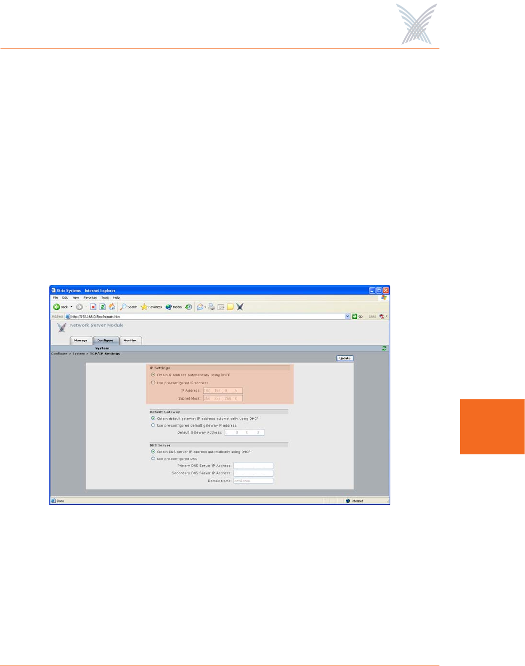
TCP/IP Settings
This command is similar to the TCP/IP Settings command used at the network level,
with the addition of the IP Settings option. For all other TCP/IP configuration
options, go to “TCP/IP Settings” on page 78.
Figure 112. TCP/IP Settings (Module Level)
◗IP Settings
Choose whether you want the system to use DHCP to obtain the module’s IP
address automatically (default), or use a pre-configured static IP address. If
you choose the latter option, you must enter a valid IP address and Subnet
Mask in the appropriate fields.

Access / One® Network
144 Managing Modules
7
When finished, click on the Update button to update this page and apply your
changes, then click on the Reboot button to reboot the module. If necessary, you
can click on the Refresh button in the toolbar to reset all parameters on this page to
their original values.
Priority/One - Class of Service
This command is the same as its corresponding command at the network level. To
configure these options for the module, go to “Priority/One - Class of Service” on
page 81.
When finished, click on the Update button to update this page and apply your
changes, then click on the Reboot button to reboot the module. If necessary, you
can click on the Refresh button in the toolbar to reset all parameters on this page to
their original values.
Radius Accounting
This command is the same as its corresponding command at the network level. To
configure these options for the module, go to “Radius Accounting” on page 84.
When finished, click on the Update button to update this page and apply your
changes, then click on the Reboot button to reboot the module. If necessary, you
can click on the Refresh button in the toolbar to reset all parameters on this page to
their original values.
Syslog
This command is the same as its corresponding command at the network level. To
configure these options for the module, go to “Syslog” on page 85.
When finished, click on the Update button to update this page and apply your
changes, then click on the Reboot button to reboot the module. If necessary, you
can click on the Refresh button in the toolbar to reset all parameters on this page to
their original values.
Access / One® Network
Managing Modules 145
7
Date and Time
This command is the same as its corresponding command at the network level. To
configure these options for the module, go to “Date and Time” on page 88.
When finished, click on the Update button to update this page and apply your
changes, then click on the Reboot button to reboot the module. If necessary, you
can click on the Refresh button in the toolbar to reset all parameters on this page to
their original values.
Operating Environment
This command is the same as its corresponding command at the network level. To
configure these options for the module, go to “Operating Environment” on page 91.
When finished, click on the Update button to update this page and apply your
changes, then click on the Reboot button to reboot the module. If necessary, you
can click on the Refresh button in the toolbar to reset all parameters on this page to
their original values.
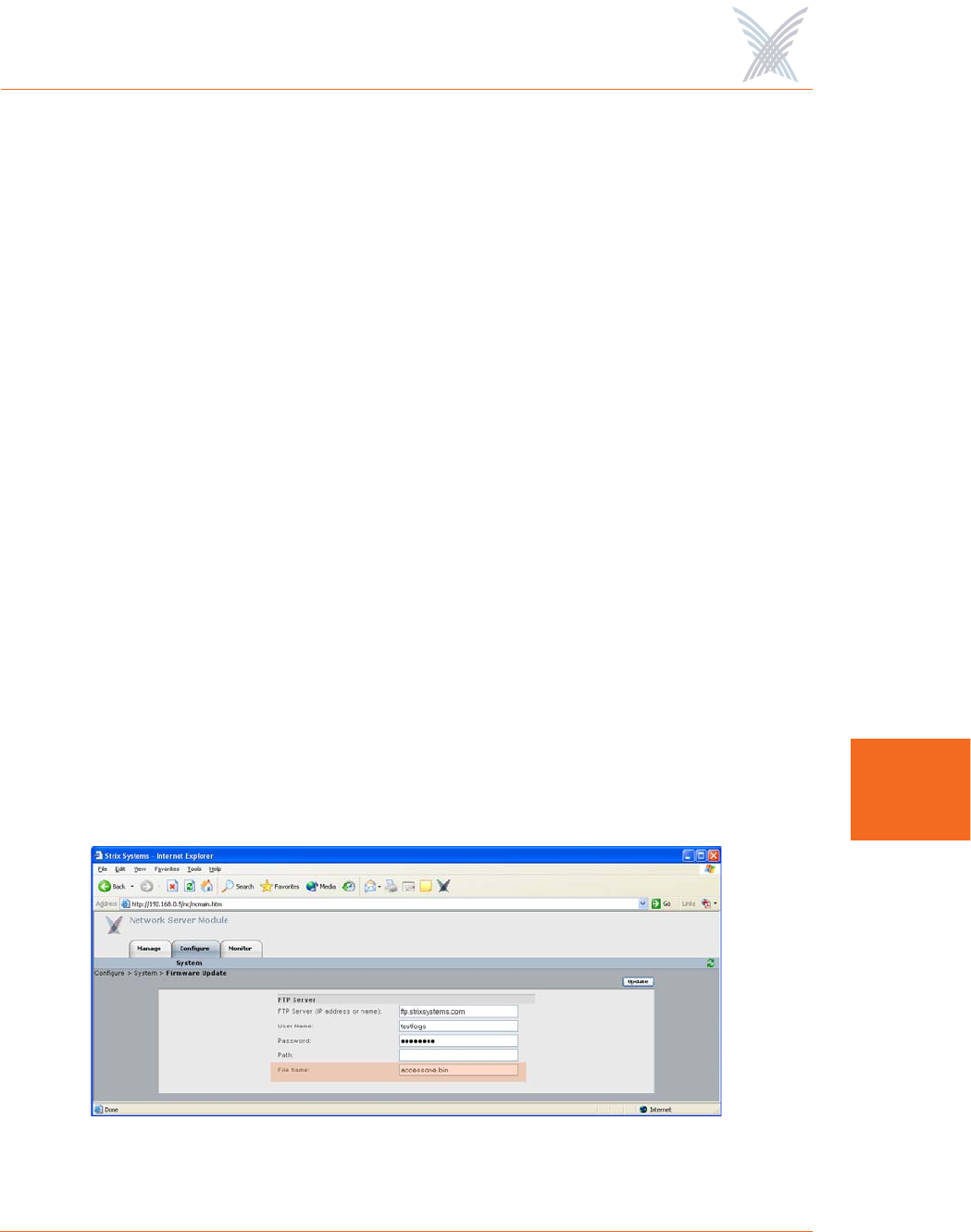
Firmware Updates
This option is similar to the Firmware Updates command used at the network level,
but without the FTP Update Aggressiveness options, and with the addition of the File
Name field (for defining a new configuration file). For all other Firmware Updates
configuration options, go to “Firmware Updates” on page 91.
Figure 113. Setting Up the FTP Server (Module Level)

Access / One® Network
146 Managing Modules
7
◗File Name
If you are calling a file other than accessone.bin or accessone_m.bin for this
module, enter the name of the file in this field.
When finished, click on the Update button to update this page and apply your
changes, then click on the Reboot button to reboot the module. If necessary, you
can click on the Refresh button in the toolbar to reset all parameters on this page to
their original values.
Wi-Fi
This area of Manger/One applies only to wireless modules (not network servers) and
contains commands that allow you to configure the module’s Wi-Fi parameters. Any
configuration parameters that you apply to the module will supersede the equivalent
system-level parameters that were applied at the network level and propagated to
the module from the Apply Configuration tab.
The menu structure under the Wi-Fi option is slightly different, depending on
whether you are logged in to a single band wireless module or a dual band wireless
module. The differences between the menus are as follows:
Figure 114. Single and Dual Band Wi-Fi Menu Structure
◗Wi-Fi (single band radio)
•Radio Parameters
•Client Connect
•Network Connect
•Rogue Scan
◗Wi-Fi (dual band radio)
•802.11a Radio
–Parameters
–Client Connect
–Network Connect
–Rogue Scan
•802.11g Radio
–Parameters
–Client Connect
–Network Connect
–Rogue Scan
Access / One® Network
Managing Modules 147
7
Radio Parameters
This command is similar to the Radio Parameters command used at the network
level, but with fields that are relevant only to the selected wireless module. To avoid
confusion, the page generated by this command will be documented here in full. All
changes made to this page will be applied only to the module you are currently
logged in to (not to the entire network).
Strix Systems complies with FCC requirements for both DFS (Dynamic Frequency
Selection) and TPC (Transmitter Power Control).
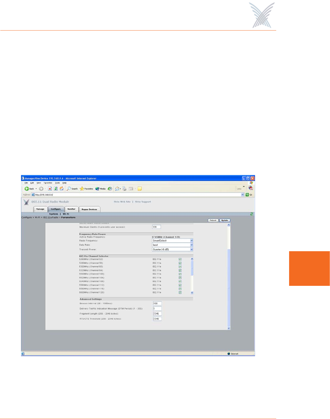
Figure 115 shows an example of the Radio Parameters configuration page for
802.11a radios operating in the 5.250 Ghz to 5.350 GHz, 5.470 GHz to 5.725
GHz, and 5.745 GHz to 5.825 GHz wireless bands.
Figure 115. 802.11a Radio Parameters
Access / One® Network
148 Managing Modules
7
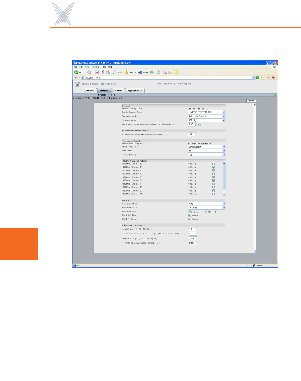
Figure 116 shows an example of the Radio Parameters configuration page for
802.11g radios operating in the 2.400 GHz to 2.4835 GHz wireless band.
Figure 116. 802.11g Radio Parameters (2.400 GHz to 2.4835 GHz)
Access / One® Network
Managing Modules 149
7
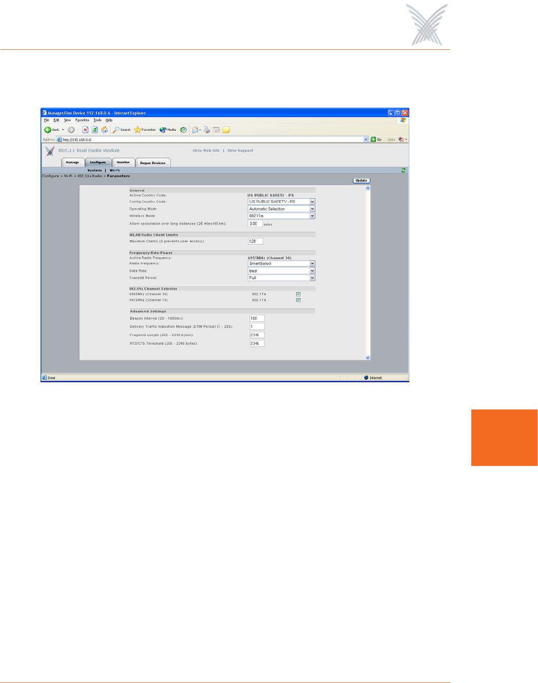
Figure 117 shows an example of the Radio Parameters configuration page for radios
operating in the 4.940 GHz to 4.990 GHz wireless band.
Figure 117. Public Safety Radio Parameters (4.940 GHz to 4.990 GHz)
The following options are available with the Radio Parameters command:
◗Active Country Code
This field (not editable) shows the currently active country code.
◗Config Country Code
This field is not editable because this model of your Access/One Network
applies only to the United States (which is the only country code available).
◗Operating Mode
This option allows you to select the operating mode (either Client Connect or
Network Connect) manually, or choose Automatic Selection if you want the
module to select its operating mode automatically.

Access / One® Network
150 Managing Modules
7
◗Wireless Mode
This option allows you to select the wireless mode for this module. The
following modes are available:
•802.11a
–This is the default standard 802.11a wireless mode.
•802.11g
–802.11g: This is the default standard 802.11g wireless mode.
–802.11g Only: This mode restricts the module to the 802.11g
wireless mode only and does not allow 802.11b compatibility.
–802.11g Super: This mode provides support for the Atheros Super G
FastFrames throughput enhancement technology, with data rates up
to 108Mbps and compatible with the 802.11g (54 Mbps) wireless
technology. This translates to nearly double the throughput, but there
are some limitations, including:
–Only one operating channel is supported.
–All user devices must also be capable of running 802.11g Super
G and be configured for it. Super G is not an industry standard
and so not all 802.11g user devices support this feature.
–802.11b Only (No 802.11g): This mode restricts the module to the
802.11b mode only and does not allow 802.11g compatibility.
◗Allow Association Over Long Distances
This option allows you to set a distance (up to 25 miles) for wireless
associations over long distances (the default is 3 miles).
◗WLAN Radio Client Limits
This option allows you to restrict the number of clients that can associate with
the module. The default is 128. Setting this field to 0 (zero) prevents all client
access to the module.

Access / One® Network
Managing Modules 151
7
◗Frequency/Rate/Power
These options define the operating frequency, data rate and transmit power
for the module. The fields for these options include:
•Active Radio Frequency
This field displays the active radio frequency that this module is currently
using.
•Radio Frequency
This option allows you to manually change the operating frequency from
the frequencies available in the pull-down list. Alternatively, you can
choose the SmartSelect option which will instruct the system to select the
best frequency automatically.
•Data Rate
This option allows you to select the data rate for the wireless module
from the choices available in the pull-down list. All data rates are
specified in Mbps (Megabits per second). You can choose a specific data
rate from the pull-down list, or choose the Best option, which will
instruct the system to select the best data rate for the wireless module
automatically. The available data rates are determined by which type of
wireless module (802.11a or 802.11g) you are logged in to.
•Transmit Power
This option allows you to select the level of transmit power for the
wireless module from the choices available in the pull-down list (either
Full, Half, Quarter, One Eighth, or Minimum). You can decrease the
transmit power to decrease the range of the module. The default value for
this parameter is Full (maximum power).
Depending on the selected antenna(s) for your application—especially
relevant to the OWS—it may be necessary to configure the transmit
power. It is the installer's responsibility to ensure that the transmit power
is set correctly for the chosen antenna(s). Operation in a manner other
than is represented in this document is a violation of FCC rules.
For a complete listing of the maximum power settings allowed for
antennas, go to “Power Settings for Antennas” on page 167.

Access / One® Network
152 Managing Modules
7
◗802.11a Channel Selector
These options extend the range of 802.11a wireless capability by allowing
you to select 802.11a wireless channels. Check the corresponding box to
enable an 802.11a channel of your choice.
◗802.11g Channel Selector
These options extend the range of 802.11g wireless capability by allowing
you to select 802.11g wireless channels. Check the corresponding box to
enable an 802.11g channel of your choice.
◗802.11g (only)
These options allow you to set up how your 802.11g wireless module
performs (not applicable to 802.11a radios). Options that are specific to
802.11g radios include:
•Protection Mode
This is a mechanism to let 802.11g devices know when they should use
modulation techniques to communicate with another 802.11b device,
especially in wireless networks where there is a mixed environment that
has 802.11g and 802.11b clients (and the clients are hidden from each
other. The protection mode options are:
–None
This assumes there are no wireless stations using 802.11b (11 Mbps)
technology. If operating in a mixed 802.11b/g network with minimal
802.11b traffic, choose this option to ensure the best performance for
your 802.11g stations.
–Always
Protects 802.11b traffic from colliding with 802.11g traffic. This
mode is not recommended, especially if only a few wireless stations
are operating with 802.11b. Only use this mode in environments
with heavy 802.11b traffic or where there is interference.

Access / One® Network
Managing Modules 153
7
–Auto
This is the default mode and will enable protection for 802.11g
stations if your Access/One Network finds an 802.11b client. In this
mode, if the 802.11b client leaves the network the protection mode
will revert to None automatically.
•Protection Rate
Sets the data rate at which the RTS-CTS (Request-to-Send and Clear-to-
Send) packets are sent (either 1 Mbps, 2 Mbps, 5.5 Mbps, or 11 Mbps).
The 11 Mbps data rate is the default.
•Protection Type
This option is only relevant when the Protection Mode is on. The options
here are CTS-only or RTS-CTS. With CTS-only, the client is not required
to send an RTS (Request-to-Send) to the AP. As long as the client receives
a CTS (Clear-to-Send) frame from the AP then the client is free to send
data. With the RTS-CTS option enabled, the client is required to send an
RTS to the AP and wait for a CTS from the AP before it can send data (this
option creates additional overhead and can cause performance
degradation). The default is CTS-only.
•Short Slot Time
802.11g defines the long slot time as 20 microseconds and a short slot
time as 9 microseconds. 802.11b only supports the long slot time of 20
microseconds. In an environment with 802.11g devices only, this option
(Short Slot Time) must be enabled for better performance—giving
precedence to 802.11g traffic. Only disable this option in mixed
(802.11b and 802.11g) environments. The default is enabled.
•Short Slot Preamble
Short slot preamble improves network efficiency by reducing the
preamble from 128 bits to 56 bits. 802.11g is required to support both
short and long preambles (802.11b support for a short preamble is
optional). If this option is enabled, any 802.11b clients associated with
the network must support a short preamble. The default for this option is
enabled.

Access / One® Network
154 Managing Modules
7
◗Advanced Settings
These advanced settings are preconfigured with the optimum settings for your
wireless module. Changing any of these settings may negatively affect the
module’s performance. For best results, leave these settings at their default
values.
•Beacon Interval
The beacon is a uniframe system packet broadcast by the AP to keep the
module synchronized. Enter a value in this field between 20 and 1000
(milliseconds) that specifies the beacon interval. The default value is 100.
•Delivery Traffic Indication Message (DTIM Period)
Enter a value between 1 and 255 that specifies the Delivery Traffic
Indication Message (DTIM). Increasing this interval allows the station to
sleep for longer periods of time resulting in power savings (in exchange
for some degradation in performance). The default value is 1.
•Fragment Length
Enter a value between 256 and 2346. This setting determines the size of
the wireless frame. Wireless frames are reassembled by the wireless
module before being forwarded to the Ethernet port, but only if the frame
is smaller than the Ethernet MTU (1536 bytes). The default value is 2346.
•RTS/CTS Threshold
This is a value that determines at what frame length the RTS-CTS function
is triggered. By default, the threshold is set at its highest value. A lower
value means that the RTS-CTS function is triggered for smaller frame
lengths. A lower threshold value may be necessary in environments with
excessive signal noise or hidden nodes, but may result in some
performance degradation. Enter a value between 256 and 2346 to specify
the RTS/CTS threshold. The default value is 2346.
When finished, click on the Update button to update this page and apply your
changes, then click on the Reboot button to reboot the module. If necessary, you
can click on the Refresh button in the toolbar to reset all parameters on this page to
their original values.
Access / One® Network
Managing Modules 155
7
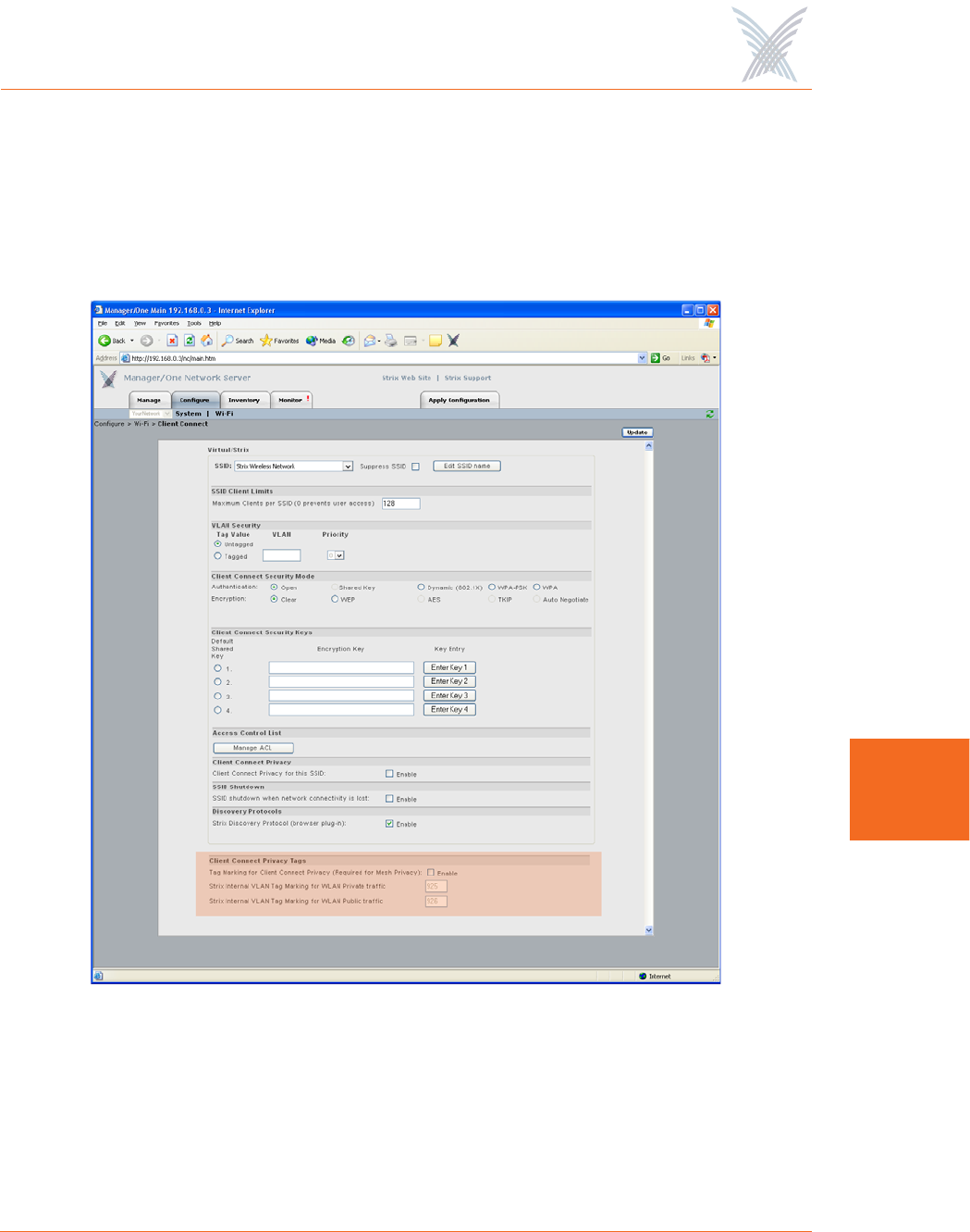
Client Connect
This command is similar to its corresponding command at the network level. The
only difference between the configuration windows is that the Client Connect
Privacy Tags option is not displayed at the module level. To configure your Client
Connect options for a wireless module, go to “Client Connect” on page 101.
Figure 118. Client Connect Configuration Window
When finished, click on the Update button to update this page and apply your
changes, then click on the Reboot button to reboot the module. If necessary, you
can click on the Refresh button in the toolbar to reset all parameters on this page to
their original values.
Access / One® Network
156 Managing Modules
7
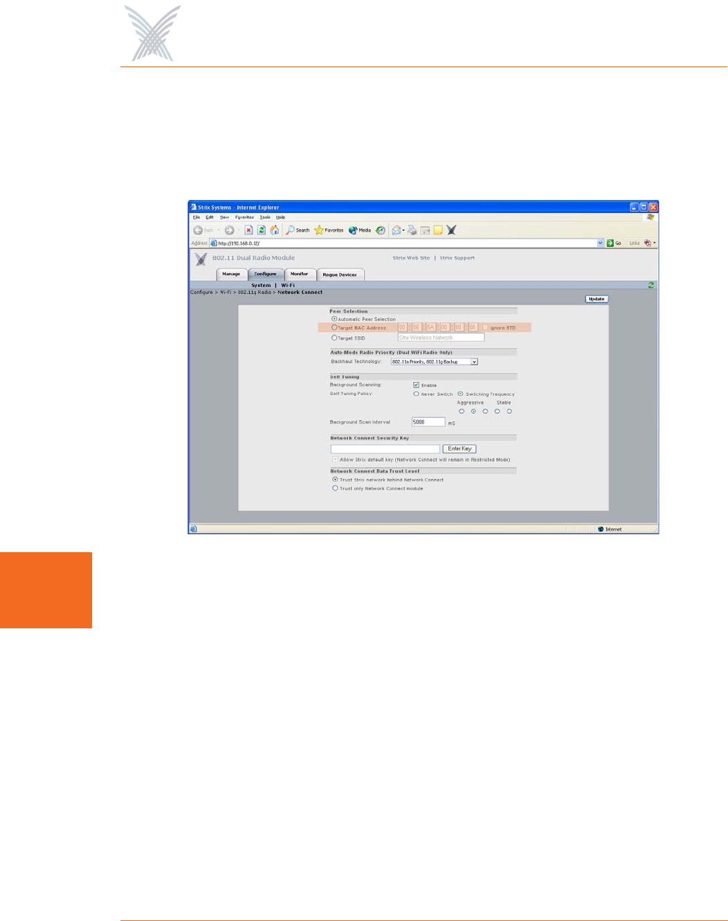
Network Connect
This command is similar to its corresponding command at the network level, with
the addition of the Target MAC Address and Ignore RTD options. For all other
configuration options, go to “Network Connect” on page 109.
Figure 119. Network Connect Configuration Window
◗Target MAC Address
Enter the MAC address for the wireless module to enable peer-to-peer
connectivity based on the module’s MAC address. You only need to complete
the MAC address (the first three fields are inputted automatically).
◗Ignore RTD
Check this box to instruct the system to ignore the RTD (Round Trip Delay),
which ensures that the backhaul will stay connected to an AP even if the RTD
is zero. When RTD from a Client Connect is set to 0 (zero) a Network
Connect will drop its wireless connection to that Client Connect and scan for
a peer with a non zero RTD (that can ping the gateway). Ignoring the RTD
will keep the link up to that peer regardless, and eliminate self-healing. The
default is to ignore the RTD (enabled).

Access / One® Network
Managing Modules 157
7
When finished, click on the Update button to update this page and apply your
changes, then click on the Reboot button to reboot the module. If necessary, you
can click on the Refresh button in the toolbar to reset all parameters on this page to
their original values.
Rogue Scan
This option allows you to define which channels are scanned for rogue devices by
the defined country code (similar to its corresponding command at the network
level, but without the option for defining a rogue list refresh period). To configure
rogue scan channel selections for the module, go to “Rogue Scan” on page 114.
When finished, click on the Update button to update this page and apply your
changes, then click on the Reboot button to reboot the module. If necessary, you
can click on the Refresh button in the toolbar to reset all parameters on this page to
their original values.

Access / One® Network
158 Managing Modules
7
The Monitor Function
This function provides you with the tools you need to monitor the performance of
individual modules and includes the following commands:
◗Reports
•Radio Statistics
Applicable to wireless modules only.
•Wireless Neighbors
Applicable to wireless modules only.
•Wireless Client Monitor
Applicable to wireless Client Connect modules only.
•SSIDs / VLANs List
Applicable to wireless Client Connect modules only.
•Device Information
Applicable to all wireless modules and network servers.

Access / One® Network
Managing Modules 159
7
Reports
This area of Manger/One applies to all wireless modules and network servers and
contains commands that allow you to monitor the performance of individual
modules within your Access/One Network. It should be noted that the menu
structure under the Reports option is slightly different, depending on whether you
are logged in to a single band wireless module or a dual band wireless module. The
differences between the menus are as follows:
Figure 120. Single and Dual Band Reports Menu Structure
The Radio Statistics,Statistics (dual band radios only) and Wireless Neighbors
commands are only available when logged in to a wireless module—not a network
server.
The Wireless Client Monitor and SSIDs / VLANs List commands are only available
when logged in to a wireless module that is configured as a Client Connect—not a
Network Connect or network server.
The Device Information command is available for all wireless modules, including
network servers.
◗Reports (single band radio)
•Radio Statistics
•Wireless Neighbors
•Wireless Client Monitor
•SSIDs / VLANs List
•Device Information
◗Reports (dual band radio)
•802.11a Radio
–Statistics
–Wireless Neighbors
–Wireless Client Monitor
–SSIDs / VLANs List
•802.11g Radio
–Statistics
–Wireless Neighbors
–Wireless Client Monitor
–SSIDs / VLANs List
•Device Information
Access / One® Network
160 Managing Modules
7
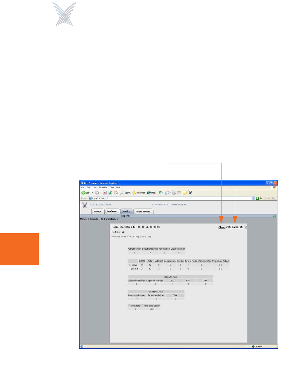
Radio Statistics
This command is used to generate a statistical performance report relative to the
selected wireless module. You can Clear the data or Recalculate the data that is
displayed on this page, as required.
Clearing the data resets all values to zero. If you recalculate (refresh) the data, the
wireless module is polled and current operating data is displayed. Clicking on the
Refresh button in the toolbar has the same effect as recalculating the data.
The following graphic shows an example of the Radio Statistics report for an
802.11a wireless module operating in the 5 GHz band with a data rate of 54 Mbps.
Figure 121. Radio Statistics
Clear
Recalculate
Access / One® Network
Managing Modules 161
7
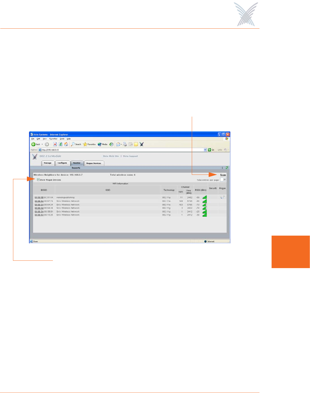
Wireless Neighbors
This command is used to generate a report that shows all wireless neighbors for the
module, including any rogue devices (if enabled). To generate the report, click on
the Scan button—it may take up to one minute to complete the scan for wireless
neighbors and return the results. To include rogue devices in the scan, simply check
the Show Rogue Devices check box. The default is to include rogue devices.
Figure 122. Wireless Neighbors
The table displayed in the Wireless Neighbors window can be customized to show a
defined number of entries in the table, and the table can be sorted in either
ascending or descending order based on any selected column. For example, if you
want to sort the table by wireless technology, click in the column header for
Technology—the table is then sorted according to the wireless technology used by
each wireless neighbor. The default is to have the table sorted by BSSID in
descending order. You can refresh the data on this page by clicking on the Refresh
button in the toolbar. In addition, you can view the RSSI legend by clicking on the
Information button (i) in the toolbar.
Scan for Neighbors
Show Rogue Devices
Access / One® Network
162 Managing Modules
7
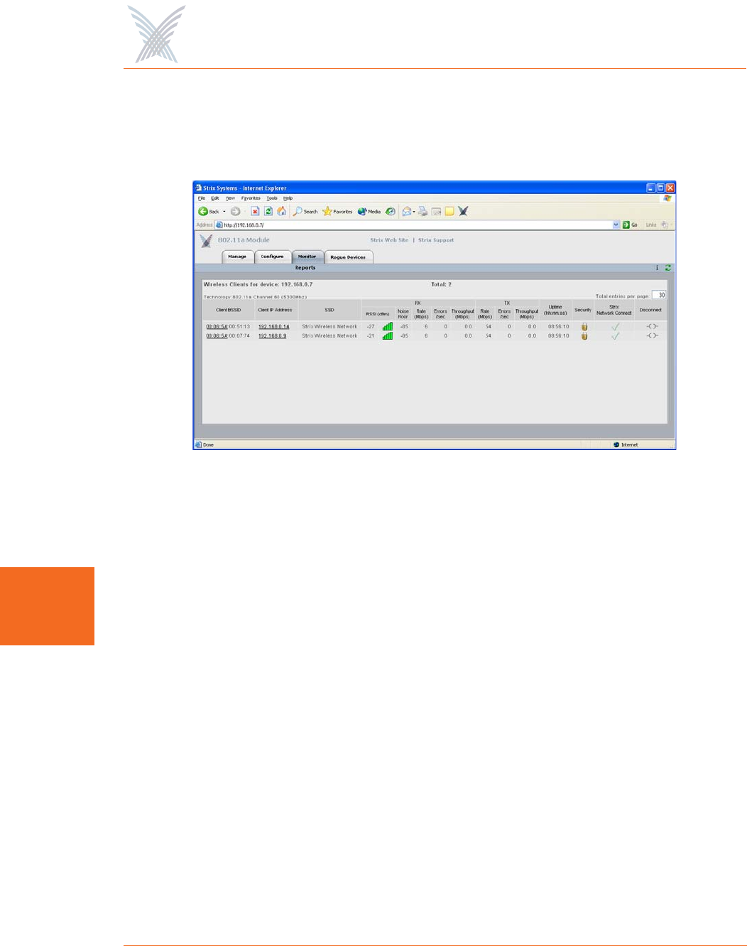
Wireless Client Monitor
This command is used to generate a report that shows all Client Connects that are
currently associated with the module you are logged in to.
Figure 123. Wireless Client Monitor
The table displayed in the Wireless Client Monitor window can be customized to
show a defined number of entries in the table, and the table can be sorted in either
ascending or descending order based on any selected column. For example, if you
want to sort the table by the IP address of each client, click in the column header for
Client IP Address—the table is then sorted according to the IP address designated for
each client. The default is to have the table sorted by Client BSSID in descending
order. You can refresh the data on this page by clicking on the Refresh button in the
toolbar. In addition, you can view the RSSI legend by clicking on the Information
button (i) in the toolbar.
If you know the username and password, you can also log in to a client by clicking
on its IP address, or you can click on a client’s BSSID and view the BSSID
information associated with the client (see also, “AP Monitor” on page 119).
The far right column offers a convenient tool for disconnecting from any of the
clients in the table—simply click on the disconnect icon in this column to
disconnect from the associated client.
Access / One® Network
Managing Modules 163
7
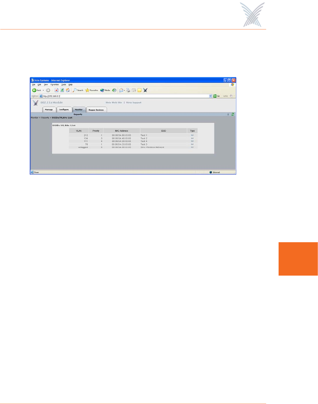
SSIDs / VLANs List
This command is used to generate a report that shows all SSIDs and VLANs currently
associated with the module you are logged in to.
Figure 124. SSID / VLANs List
The table displayed in the SSIDs / VLANs List window can be sorted in either
ascending or descending order based on any selected column. For example, if you
want to sort the table by the priority assigned to each VLAN, click in the column
header for Priority—the table is then sorted according to the VLAN priority. The
default is to have the table sorted by VLAN in descending order.
You can refresh the data on this page by clicking on the Refresh button in the
toolbar. In addition, you can view the Wi-Fi legend by clicking on the Information
button (i) in the toolbar. The legend shows the meaning of the icon displayed in the
Type column.
Client Connect (Virtual/Strix) is the system topology that enables your Access/One
Network to support and provide access to client devices using most wireless
technologies, including 802.11a or 802.11g. With Client Connect you can
customize each network node to support the wireless technologies you need in the
locations you need them. Any mix of these technologies can be supported within a
single node or across the entire Access/One Network. To understand how SSIDs and
VLANs are assigned to clients, go to “Client Connect” on page 155.
Access / One® Network
164 Managing Modules
7
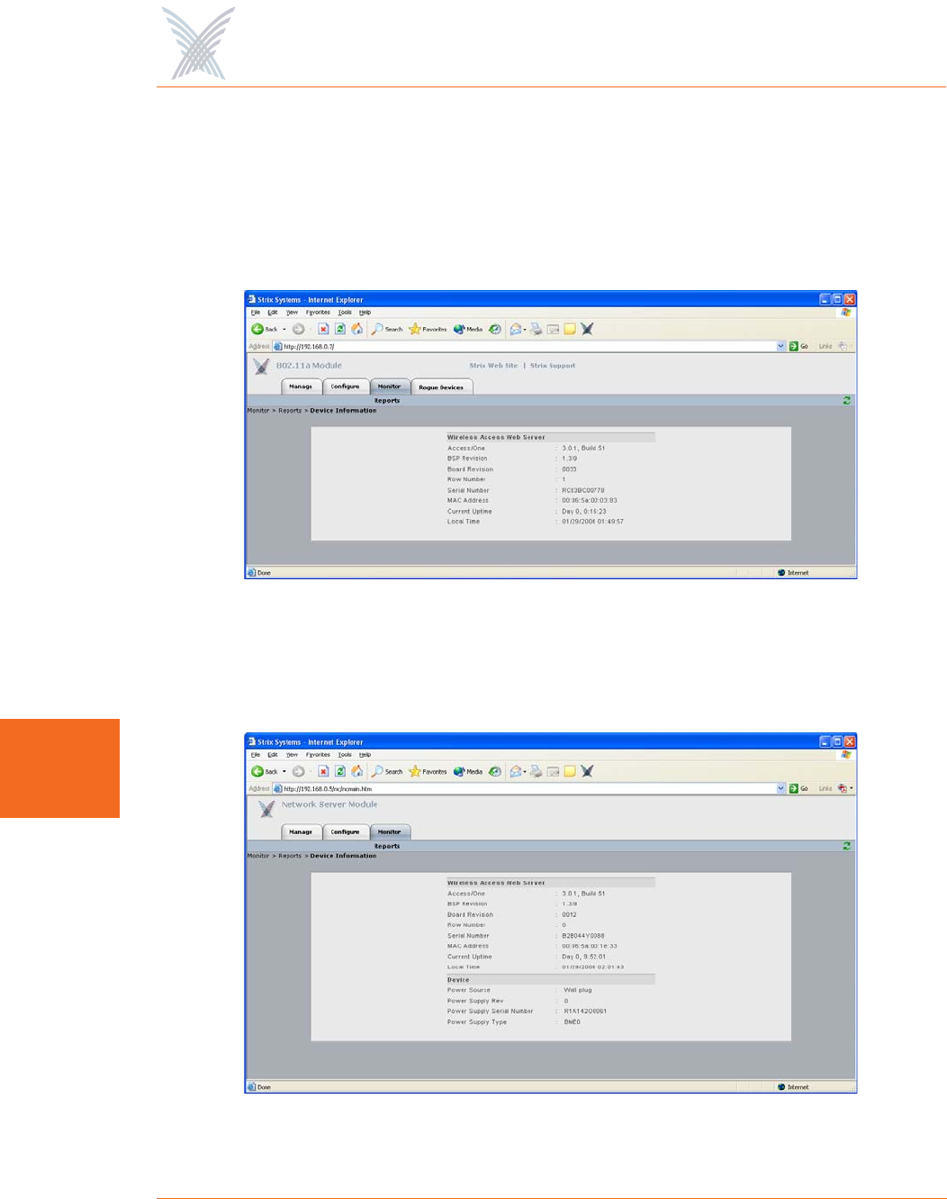
Device Information
This command is used to generate a report that shows information about the module
you are logged in to. Figure 125 shows the Device Information window generated
while logged in to an 802.11a wireless module. Unlike most monitoring windows,
pages generated by the Device Information command are not configurable.
Figure 125. Device Information (802.11a Module)
Figure 126 shows the Device Information window generated while logged in to a
network server module.
Figure 126. Device Information (Network Server)
Access / One® Network
Managing Modules 165
7
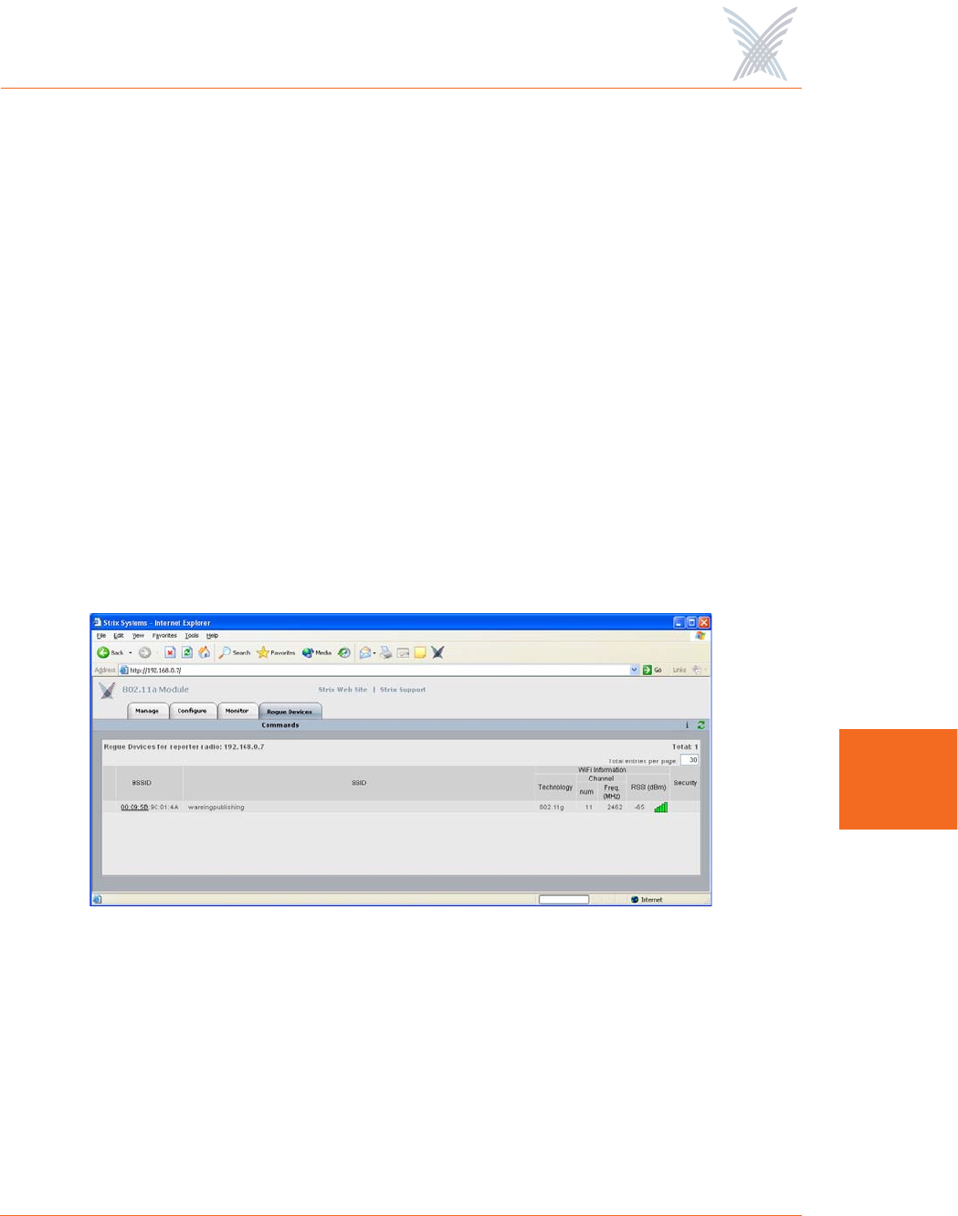
The Rogue Devices Function
This function provides you with a rogue scanning tool that allows you to scan for all
rogue devices. The scanning tool offered here is similar to the Rogue Monitor tool
provided at the network level, but applies only to rogue devices detected by the
wireless module that you are logged in to.
Commands
This area of Manger/One applies to wireless modules only.
Scan
Use this command if you want to initiate an active scan for rogue devices. Active
scans can take up to one minute to complete and traffic to and from the module will
be disrupted during the scanning process. Results from the scan are reported in the
Rogue Monitor table.
Figure 127. Rogue Monitor Table
The table displayed in the Rogue Monitor table can be sorted in either ascending or
descending order based on any selected column. For example, if you want to sort
the table by technology, click in the column header for Technology—the table is
then sorted according to the wireless technology used by the rogue device. The
default is to have the table sorted by BSSID in descending order.
Access / One® Network
166 Managing Modules
7
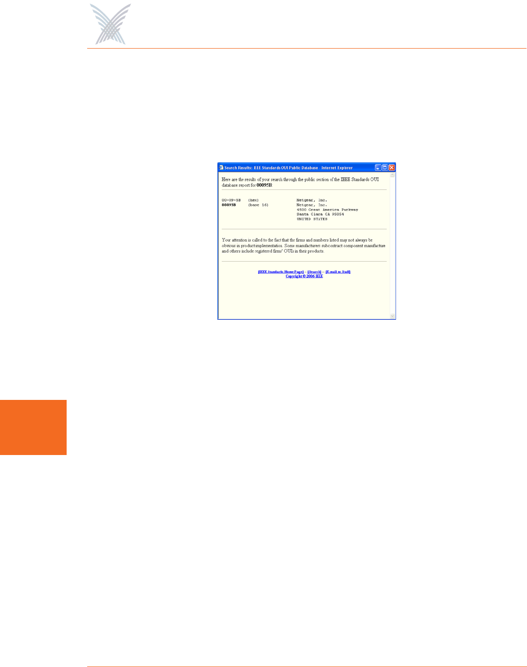
You can refresh the data on this page by clicking on the Refresh button in the
toolbar. In addition, you can view the RSSI legend by clicking on the Information
button (i) in the toolbar.
In addition, you can click on a rogue’s BSSID and view the BSSID information
associated with the rogue device. For example:
Figure 128. BSSID Information for Rogue Device
For more information about rogue devices, go to:
◗“Detecting Rogue Devices” on page 13.
◗“Rogue Scan” on page 114.
◗“Rogue Monitor” on page 123.
◗“Rogue Scan” on page 157.

Access / One® Network
167
A
Power Settings for Antennas
The following tables show the maximum power settings based on the type of
antenna1 being used and the wireless band. Strix Systems complies with FCC
requirements for both DFS (Dynamic Frequency Selection) and TPC (Transmitter
Power Control).
Channels for IEEE 802.11b/g
1. In order to comply with FCC regulations, for transmissions in the 5.725 - 5.850 GHz
band using the 23 dBi Patch Panel antenna in the United States, a band pass filter must
be used (K&L Microwave part number 6C50-5787.5/U120-n/n or equivalent), and
also for transmissions in the 2.4 GHz band in the United States using full power on
channels 1 or 11 (RF Linx Corporation part number 2400BPF-8-FB or equivalent).
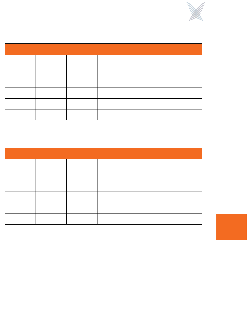
12 dBi Omni Antenna (2.4 GHz – 2.4835 GHz)
Channel
Identifier
Frequency
(MHz) Filter
Power Level (dBm) *
CCK ODFM
1 2412 Yes Half (+24dBm) Half (+23dBm)
2 2417 Yes Half (+24dBm) Half (+23dBm)
3 2422 Yes Half (+24dBm) Half (+23dBm)
4 2427 Yes Half (+24dBm) Half (+23dBm)
5 2432 Yes Half (+24dBm) Half (+23dBm)
6 2437 Yes Half (+24dBm) Half (+23dBm)
7 2442 Yes Half (+24dBm) Half (+23dBm)
8 2447 Yes Half (+24dBm) Half (+23dBm)
9 2452 Yes Half (+24dBm) Half (+23dBm)
10 2457 Yes Half (+24dBm) Half (+23dBm)
11 2462 Yes Half (+24dBm) Half (+23dBm)

Access / One® Network
168
A
* Listed power level settings are average power.
* Listed power level settings are average power.
16.4 dBi Sector Antenna (2.400 GHz – 2.4835 GHz)
Channel
Identifier
Frequency
(MHz) Filter
Power Level (dBm) *
CCK ODFM
1 2412 Yes Quarter (+21dBm) Quarter (+20dBm)
2 2417 Yes Quarter (+21dBm) Quarter (+20dBm)
3 2422 Yes Quarter (+21dBm) Quarter (+20dBm)
4 2427 Yes Quarter (+21dBm) Quarter (+20dBm)
5 2432 Yes Quarter (+21dBm) Quarter (+20dBm)
6 2437 Yes Quarter (+21dBm) Quarter (+20dBm)
7 2442 Yes Quarter (+21dBm) Quarter (+20dBm)
8 2447 Yes Quarter (+21dBm) Quarter (+20dBm)
9 2452 Yes Quarter (+21dBm) Quarter (+20dBm)
10 2457 Yes Quarter (+21dBm) Quarter (+20dBm)
11 2462 Yes Quarter (+21dBm) Quarter (+20dBm)
Access / One® Network
169
A
Channels for IEEE 802.11a
* Listed power level settings are average power.
* Listed power level settings are average power.
12 dBi Omni Antenna (5.250 GHz – 5.350 GHz)
Channel
Identifier
Frequency
(MHz) Filter
Power Level (dBm) *
ODFM
52 5260 No Quarter (+17dBm)
56 5280 No Quarter (+17dBm)
60 5300 No Quarter (+17dBm)
64 5320 No Quarter (+17dBm)
23 dBi Patch Panel Antenna (5.250 GHz – 5.350 GHz)
Channel
Identifier
Frequency
(MHz) Filter
Power Level (dBm) *
ODFM
52 5260 No Minimum (+5dBm)
56 5280 No Minimum (+5dBm)
60 5300 No Minimum (+5dBm)
64 5320 No Minimum (+5dBm)

Access / One® Network
170
A
* Listed power level settings are average power.
12 dBi Omni Antenna (5.470 GHz – 5.725 GHz)
Channel
Identifier
Frequency
(MHz) Filter
Power Level (dBm) *
ODFM
100 5500 No Quarter (+17dBm)
104 5520 No Quarter (+17dBm)
108 5540 No Quarter (+17dBm)
112 5560 No Quarter (+17dBm)
116 5580 No Quarter (+17dBm)
120 5600 No Quarter (+17dBm)
124 5620 No Quarter (+17dBm)
128 5640 No Quarter (+17dBm)
132 5660 No Quarter (+17dBm)
136 5680 No Quarter (+17dBm)
140 5700 No Quarter (+17dBm)

Access / One® Network
171
A
* Listed power level settings are average power.
23 dBi Patch Panel (5.470 GHz – 5.725 GHz)
Channel
Identifier
Frequency
(MHz) Filter
Power Level (dBm) *
ODFM
100 5500 No Minimum (+5dBm)
104 5520 No Minimum (+5dBm)
108 5540 No Minimum (+5dBm)
112 5560 No Minimum (+5dBm)
116 5580 No Minimum (+5dBm)
120 5600 No Minimum (+5dBm)
124 5620 No Minimum (+5dBm)
128 5640 No Minimum (+5dBm)
132 5660 No Minimum (+5dBm)
136 5680 No Minimum (+5dBm)
140 5700 No Minimum (+5dBm)

Access / One® Network
172
A
* Listed power level settings are average power
* Listed power level settings are average power
12 dBi Omni Antenna (5.745 GHz – 5.825 GHz)
Channel
Identifier
Frequency
(MHz) Filter
Power Level (dBm) *
ODFM
149 5745 No Half (+23dBm)
153 5765 No Full (+26dBm)
157 5765 No Full (+26dBm)
161 5805 No Full (+26dBm)
165 5825 No Half (+23dBm)
23 dBi Patch Panel Antenna (5.745 GHz – 5.825 GHz)
Channel
Identifier
Frequency
(MHz) Filter
Power Level (dBm) *
ODFM
149 5745 Yes Half (+23dBm)
153 5765 Yes Full (+26dBm)
157 5765 Yes Full (+26dBm)
161 5805 Yes Full (+26dBm)
165 5825 Yes Half (+23dBm)