Stryker Instruments 5100 TPS Console and TPS Irrigation Console RFID User Manual 5100 001 709 pmd 334
Stryker Instruments TPS Console and TPS Irrigation Console RFID 5100 001 709 pmd 334
Manual

1
IMPORTANT INFORMATION: File this in your TPS records
Total Performance System Consoles
REF 5100-1 Console
REF 5100-50 Irrigation Console
Hermes READY™
REF 5100-201 Console
REF 5100-250 Irrigation Console
User's Guide
••••••••••••••••••••••
Includes setup, safety, repair, and warranty information for the
Stryker Total Performance System.
For answers to questions about other equipment, see the
information supplied with that equipment.
4100 E. Milham
Kalamazoo, Michigan
(USA) 49001
1-800-253-3210
1-269-323-7700
5100-001-709 Rev-A6/03
Version
4.0 US Patents D398,598; D415,134; 5,543,695; 5,689,159; 6,017,354;
6,025,683; 6,045,564; 6,329,778 and other patents pending
2

3
Software License Notice
Stryker® TPS™ Surgical Tool System products contain software that is installed in the products by Stryker Corporation. Stryker Corpora-
tion owns this software; this software is never sold. Each sale of a software containing product is not a sale of such software; it includes
only a license to use the software in the product in which the software was initially installed.
Any license granted by Stryker Corporation to use the software contained in its; products does not give the licensee the right to copy,
alter, disassemble, reverse engineer, create derivative works of such software or to use such software in either original or modified form in
any product other than the Stryker Corporation product in which the software was initially installed by Stryker Corporation.
Contents
Software License Notice .................................................................................... 3
Where to Find Answers ...................................................................................... 4
Warning, Caution, Note Defined ........................................................................ 4
Important Safety Instructions ............................................................................ 5
System Overview
Symbol Definition................................................................................................6
Operating Instructions
Connecting the Equipment
Hermes READY™ TPS Consoles....................................................................... 7
The Control Screen
TPS Start-Up Screen
No Handpiece Detected Screen ......................................................................... 8
Functions of the Control Screen
Elements of the Control Screen......................................................................... 9
Select Your System Settings
Standard Features............................................................................................. 10
Quick Reference Guide (Icon Definition) .......................................................... 11
Handpiece Screens
Saw Handpiece Screen (TPS Oscillating and Sagittal Saws) ........................... 12
Rotary Handpiece Screen
(TPS Universal and MicroDrills & TPS MicroDriver) ...........................................13
Stryker Endoscopy and Leibinger Handpiece Screen
(SE5 hand-controlled Endo Shaver, QuadraCut Shaver, QuadraCut Bone Plug,
and QuadraCut Small Joint, Hummer 4, Formula, 6K Micro, 12K Micro) ........... 14
Other Screens
Main Option Screen .......................................................................................... 15
System Information Screen..............................................................................16
Handpiece Adjustment Screen ........................................................................ 17
Console Adjustment Screen ............................................................................18
Footswitch Adjustment Screen........................................................................19
Footswitch Button Mapping Screen................................................................ 20
Handpiece Button Mapping Screen.................................................................21
Surgeon Preference Screen ............................................................................. 22
Messages and Error Messages ....................................................................... 23
Specifications .................................................................................................... 24
Federal Communications Commission Compliance Statement ................... 24
Repair/Loaner Program
Limited Warranty ............................................................................................... 25
Stryker International Subsidiaries ................................................................... 26
© 2003, Stryker Corporation

4
Where to Find Answers
When you have questions about your Stryker TPS products, there are several places to
find the answers.
In this book
Use this book to set up your system and select console options. This book also
contains information on system safety, repair, and component warranty.
............................................................................................................................................
In TPS component instructions
For answers to questions about any TPS handpiece, attachment, or component , see
the information supplied with that component. A copy of TPS Cleaning, Maintenance
and Sterilization Recommendations is also supplied with each component.
............................................................................................................................................
From your Stryker Sales Representative
If you can't find an answer in any of the materials provided or you have questions
about other Stryker Instruments products, call your Stryker Sales Representative.
............................................................................................................................................
From Stryker Customer Service
Please contact our Customer Service Department to order product information
literature, a cutting accessories guide, additional TPS maintenance manuals, and
component instructions by dialing 1-800-253-3210. Outside the U.S.A., contact your
nearest Stryker subsidiary.
............................................................................................................................................
See the TPS Cleaning, Maintenance, and Sterilization Recom-
mendations booklet for care information.
Warning • Caution • Note
This symbol is used to alert the reader to important safety and precautionary information.
When displayed on the actual device, it refers the user to accompanying documents.
Please read this manual and follow all instructions carefully. The words WARNING, CAUTION and
NOTE carry special meanings and should be carefully reviewed.
WARNING: The personal safety of the patient and/or user may be involved. Disregarding this
information could result in injury to the patient and/or operating room staff.
CAUTION: These instructions point out special service procedures or precautions that must be
followed to avoid damaging the instrument.
NOTE: This provides special information to make maintenance easier or important instructions
more clear.

5
IMPORTANT SAFETY INSTRUCTIONS
SYSTEM SAFETY
!!
!!
!DO NOT modify ground of power cord.
!Equipment not suitable for use in the presence of
flammable anesthetic mixture with air or with oxygen or
nitrous oxide.
!The Stryker Total Performance System is designed to
be used by persons familiar with surgical procedures.
Misuse may cause injury to both patient and system
components. Prior to each use, system components
should be inspected for damage. DO NOT use if
damage is apparent.
!Use only Stryker TPS components and accessories
unless otherwise specified.
!Clean and sterilize handpieces and accessories before
first and every use.
!Use of safety glasses by user and operating room staff
is recommended to prevent eye injuries.
HANDPIECE SAFETY
!Read this booklet and the information supplied
with your TPS components. Component instruc-
tions provide specific safety information. Refer to
the instructions supplied with Stryker Endoscopy
handpieces when using those handpieces in
conjunction with the TPS console.
!DO NOT attempt to change a saw, bur, or drill while
handpiece is running.
!Stryker handpieces which fail due to long life and/or
nose bearing failure may allow foreign matter to
migrate or emit from the distal tip of the handpiece.
Fluid may leak into the surgical site, such that mea-
sures may be required, per the physician's discretion,
to protect the patient from infection.
!Never rest handpiece on the patient. Improper
handling of a handpiece could result in damage or
burns to tissue.
!Do not place a TPS handpiece near or on a magnetic
pad or tray. The magnetic field can simulate a Univer-
sal Handswitch and may cause the handpieces to run
inadvertently.
!DO NOT modify any bur to fit the handpieces. Use
only Stryker approved burs. Other burs may not fit
properly in the handpiece. During use they may come
out of the handpiece or bend which would result in
damage to tissue in the surgical site due to loss of
control of the bur.
!Burs and blades are intended for single use only.
!Excessive pressure, such as bending or prying, may
cause accessory to bend or break and cause tissue
damage to patient and/or operating room staff.
!Heavy sideloads and/or long operating periods
occasionally will cause overheating of the distal tip and
the body of handpieces to the point where the hand-
piece is uncomfortable to hold or causes injury to the
patient.
!If the recommended duty cycle is not followed, the
handpiece may overheat and cause injury to patient
and/or operating room staff. See the Duty Cycle
information supplied with each handpiece.
!Excessive pressure, such as bending and/or prying
with a bur, may cause the bur to bend or fracture. If
operated at a high speed, it is possible that the bur will
bend yet further. This could result in damage to tissue
in the surgical site, handpiece vibration that causes lost
tactile control, or breakage of the bur such that the
broken piece would be ejected at a high velocity
endangering the patient and/or operating room staff. It
is therefore recommended that safety glasses be used.
!Excessive pressure, such as bending and prying with
blade, may cause the blade to bend or fracture and
could result in damage to tissue in the surgical site
and/or loss of tactile control.
!If using a device with a safety lock, such as a
MicroDriver or Universal Handswitch, always place that
device in the SAFE position when not in use. IMPOR-
TANT: Be aware that the TPS footswitch will override
the Universal Handswitch SAFE setting.
!Always use the appropriate accessory combination with
a handpiece. Contact your Stryker sales representative
for a complete list of accessories. Failure to comply
may result in patient and/or operating room staff injury.
!Please note the handpiece starts with rapid accelera-
tion when the footswitch or handswitch is activated.
!During initial use of your TPS handpieces, monitor the
heat response in relation to the type of surgical
procedure being performed. Frequently check the
distal tip and body until you are familiar with its
temperature rise characteristics. Failure to pay close
attention to handpiece temperature may cause burn
injury to patient.
WARNING: The personal safety of the patient and/or user may be involved. Disregarding this information
could result in injury to the patient and/or operating room staff. Read and understand the following warnings.
6
Power ON
Power OFF
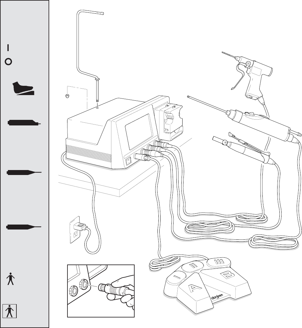
Connection Detail
System Overview
TPS Footswitch
TPS Handpiece
TPS Irrigation Console
Stryker
Endoscopy
Handpiece
TPS Handpiece
with Universal
Handswitch
Handpiece
Cords
Type B
Applied
Part
Type BF
Applied
Part
ENDO
Endoscopy
Handpiece Port
TPS2
TPS Handpiece
Port 2
TPS1
TPS Handpiece
Port 1
Symbol
Definition
Footswitch
Connector
The Stryker Total Performance System is intended for use in the cutting, drilling, decorticating, and smoothing of bone and
other bone related tissue in a variety of surgical procedures. It is also used for the placement or cutting of screws, wires,
pins, and other fixation devices as it can be used to cut metal.
TPS console powers multiple handpieces while allowing the user to program a number of customized settings. Hermes
READY™ TPS Consoles are designed to interface with Computer Motion's Hermes Operating Room Control Center. The
Hermes system allows voice control and pendant setting adjustment of the SE5 Hand Controlled Shaver REF 272-704-
100 and 12K Hand Controlled Shaver REF 272-704-500.

7
Operating Instructions
Hermes READY™ TPS Consoles
REF 5100-201 and 5100-250
A Hermes-Interface cable links the two
systems. Linking the system does not
affect the normal function of the console.
At any time, console functions may be
selected from the control screen or by
using a control accessory such as a TPS
footswitch.
WARNINGS:
!Only the Hermes Operating Room
Control Center is approved for use
with the TPS console. Do not plug
any other device into the Hermes
console port. Use of other devices
may damage the console.
!It is important to read and understand
the Hermes Operating Room Control
Center instructions; the use of the
TPS console with the Hermes
Operating Room Control Center is
explained in those instructions.
!Stryker recommends attaching an
alternate control accessory
(footswitch) to the console in the event
the Hermes System fails during
surgery.
NOTE: The port labeled DATA PORT is
intended for the manufacturer's use only.
If you have questions about using the
Hermes System with the TPS console,
contact your Stryker Endoscopy
representative or call Stryker Endoscopy
Customer Service at 1-800-624-4422.
Outside the US, contact the nearest
Stryker subsidiary.
Connecting the Equipment
This is a system overview. For specific instructions on each TPS component, refer
to the information supplied with the component.
1. Place your console on a sturdy, flat surface near a hospital grade outlet.
2. Plug the console's power cord into the recessed power socket on the back of
the console.
3. Plug the other end of the power cord into a hospital-grade wall outlet.
4. Turn on the console. The on/off switch is located on the front of the console.
NOTE: As you set up the system, the console's screen will change to indicate the
various components as they are plugged in.
5. If using a Footswitch, plug the footswitch cable into the console port marked
FOOTSWITCH. Align orientation marks and gently push connectors together.
CAUTION: All TPS Cords have push/pull connectors. Do not thread or twist for
insertion or removal.
6. Plug the handpiece cord(s) into the console port(s) identified for the hand-
piece. Align connector orientation marks and gently push connectors together.
NOTE: Ports marked TPS1 and TPS2 are for Stryker TPS handpieces only.
The port marked ENDO is intended for the following list of Stryker Endoscopy
handpieces: SE5 Handpiece REF 272-704-100, SE5 Hand-controlled REF 272-
704; QuadraCut Shaver REF 275-701; QuadraCut Bone Plug REF 275-705; and
QuadraCut small Joint REF 275-601.
NOTE: If using a TPS Universal Handswitch, attach it to the handpiece before you
plug the cord into the handpiece.
7. Plug the other end of the handpiece cord(s) into the handpiece(s).
8. Attach cutting accessories to handpieces. Instructions supplied with each
handpiece or attachment provide details for cutting accessory assembly.
WARNING: Use only Stryker approved cutting accessories.
9. If using an Irrigation Console REF 5100-50 or 5100-250, assemble Irrigation
Pole REF 5100-50-28 to the console as shown. Hang irrigation bag from pole.
Install irrigation cassette into the pump. Attach irrigation clips to handpieces and
connect tubing.
Continue to the next step if using a Hermes READY™ TPS Console and Hermes
Operating Room Control Center.
CAUTION: Use only the Hermes-Interface cable provided by Stryker Endoscopy.
10. Connect the TPS console to the Hermes controller using a Hermes-Interface cable
into the port labeled Hermes on the back of the console. Plug the other end into
any available device port on the rear panel of the Hermes controller.
11. Power up both systems and test the devices to ensure they are performing properly
prior to surgery.
WARNINGS:
!Before using this system read and understand the information in this manual and the instructions supplied with each
TPS component and Stryker Endoscopy handpieces. Pay close attention to the User/Patient Safety Information.
!Familiarization with the Total Performance System prior to use is important. If you have any questions, contact your
Stryker Instruments representative or Stryker Customer Service at 1-800-253-3210.
!Prior to use, system components should be operated and inspected for any damage. DO NOT use if damage is
apparent.

8
The Control Screen
No Handpiece Detected
Screen
This image indicates that no handpiece is at-
tached to the cord plugged into the selected port.
The screen will change to the handpiece screen
when the missing handpiece is connected to the
cord.
NOTE: This screen will also appear if the console
is unable to recognize the handpiece. This could
be caused by a handpiece that is not compatible
with the TPS console, or a faulty or damaged
handpiece or cord.
This example shows that no handpiece is attached to the cord plugged into the
TPS2 port.
TPS Start-Up Screen
This display appears on the screen every time the
console is turned on.
This display remains on the screen until a cord is
plugged into one of the TPS handpiece ports or the
OPT button is depressed.
If a handpiece cord is plugged into a handpiece
port when the console is turned on, this display
shows momentarily before changing to either a no
handpiece detected screen or to the screen of the
selected handpiece.
9
Functions of the Control Screen
The TPS console allows the user to select functions and settings such as handpiece selection, speed, and direction.
Designed to be easy to use and understand, the touch sensitive control screen allows you to set the system controls with
the touch of a finger. Interactive icons on the control panel represent system components and functions. The control
screen also provides important monitoring information for the selected handpiece.
Select system
options screen
Footswitch
indicator and
options
Handpiece
identification Handpiece
speed
TPS handpiece
select buttons
Endo handpiece
select button
Elements of the Control Screen
Attachment/
Blade
identification
Handpiece power
Indicator ramp
Surgeon
preference
indicator
Control screen visually presents options which can be set
for the selected handpiece.
Icons represent elements of your TPS system. Icons are
functional buttons. Each function may be selected by
pressing the screen where the button is displayed. When
you touch an icon, the icon appears to be pressed down
and the graphic symbol highlights to indicate that it is
activated. (See Icon Definition).
NOTE: An audible signal indicates interface with icons.
NOTE: Buttons such as the adjust arrows or OPT button
which are temporary toggles or adjustment buttons only
highlight while depressed.
NOTE: Buttons with a white background are toggle buttons.
NOTE: Options vary among different handpieces. The
console will only display the options available for a given
handpiece.
Handpiece identification displays the name of the active
handpiece. NOTE: Handpieces can be plugged into each
of the console's handpiece ports, but only one can be
selected at a time.
NOTE: When *CUSTOM* is displayed at the top of the
screen, the console's default settings are selected from
Surgeon Preferences. The console is able to capture the
preferred settings for several different users. When this
feature is activated, the preferred settings act as default
settings. See Surgeon Preference for further details.
Handpiece speed information displays the default speed
for each handpiece until you reset speed settings.
While the handpiece is running, the display shows the
actual handpiece speed. If the handpiece is not running
the default or selected speed is displayed.
NOTE: Incremental information displayed on the control
screen is accurate within +/-1%.
10
Select Your System Settings
NOTE: When the console is turned on, its default
setting is factory default unless a Surgeon Preference
setting is selected as the start up default. See Surgeon
Preference for further details.
1. Handpiece select buttons enable you to activate the
handpiece plugged into one of the three ports on the
front of the console. To display the control screen for
the handpiece plugged into the TPS1 port, touch the
corresponding handpiece select icon. The icon
highlights and appears pressed down.
NOTE: Selecting a handpiece icon activates the
corresponding handpiece and displays its specific
control screen.
2. Change the maximum handpiece speed. Press the
adjustment arrows to change the handpiece speed
setting incrementally until the desired speed is reached.
• Saws - The set point is displayed as a percentage of
maximum power and vertical line on the speed ramp.
During handpiece operation, the percentage reading
and speed ramp displays the power level.
• Rotary handpieces - The speed set point is displayed.
During handpiece operation, the current speed is
displayed.
3. Select various settings as desired. Refer to the
control screens on the following pages for details for
each handpiece.
4. Select the OPT icon to access the MAIN OPTION
screen. This screen allows access to general console
and user settings as well as direct access to each
handpiece option screen.
NOTE: The screen returns to the active handpiece
adjustments screen when the handpiece name is
touched.
5. Touch the EXIT icon to return to the active hand-
piece control screen.
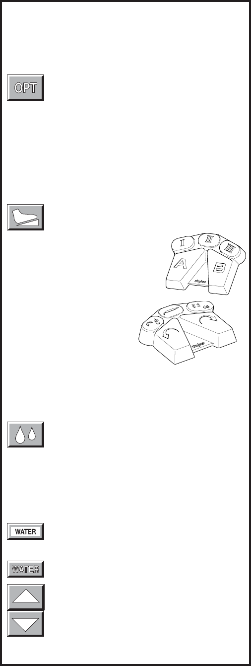
Handpiece Irrigation
Irrigation functions pertain only to consoles with the built-
in irrigation pump REF 5100-50 and 5100-250.
Press the icon to start irrigation flow while the
handpiece is running.
If irrigation is desired while the handpiece is stopped, press
and hold the icon until the pump is activated. The pump can
be turned off by touching the icon again.
Irrigation flow rate can be adjusted from the HANDPIECE
screen or the HANDPIECE ADJUSTMENTS screen.
From the HANDPIECE screen, toggle the SPEED
icon to WATER before using the arrows to adjust
flow rate. -OR-
From the HANDPIECE ADJUSTMENTS screen,
select the WATER icon and use the arrows to
adjust flow rate. Flow rate diminishes as the set-
ting approaches zero.
NOTE: Flow rate may vary among handpiece
models.
The pump can also be turned on and off with the footswitch.
Main Option Icon
The option icon appears on all handpiece screens
and allows access to the MAIN OPTION screen.
See MAIN OPTION SCREEN for further details.
Footswitch Icon
The footswitch icon only appears when a
footswitch is plugged into the console.
If using a footswitch with these graph-
ics, pedal functions can be repro-
grammed. See Footswitch Adjustments
and Footswitch Button Mapping.
A footswitch with these graphics
cannot be reprogrammed.
Standard Features
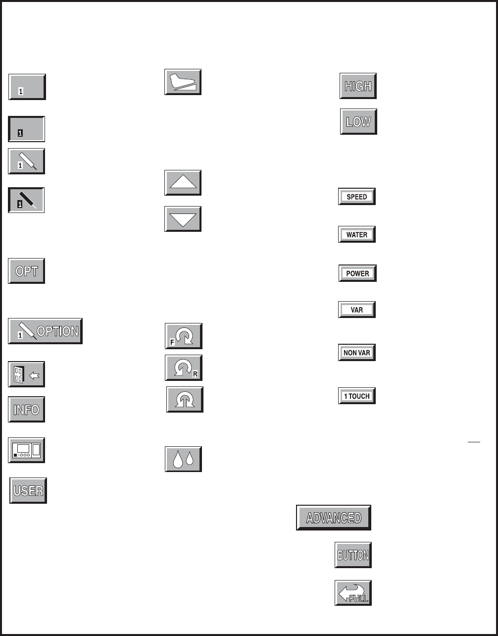
11
Direction Arrows: Sets handpiece
mode.
Forward (clockwise)
Reverse (counterclock-
wise)
Oscillate
Irrigation: Activates or
deactivates handpiece
irrigation.
System Options
Options: Gives access to
handpiece adjustments,
system information, console
adjustments and user
preference.
Handpiece option:
Accesses corre-
sponding handpiece
adjustment screens.
Exit: Returns to previous
screen.
Information: Displays system
information screen.
Console: Gives access to
console adjustment screen.
Allows access to the surgeon
Handpiece Select
This type of icon appears when
a cord (without a handpiece) is
plugged into the corresponding
Endo, TPS1 or TPS2 port.
It appears depressed when
selected.
The handpiece graphic appears
when a handpiece is attached
to the corresponding cord.
The handpiece graphic
highlights and the icon appears
depressed when selected.
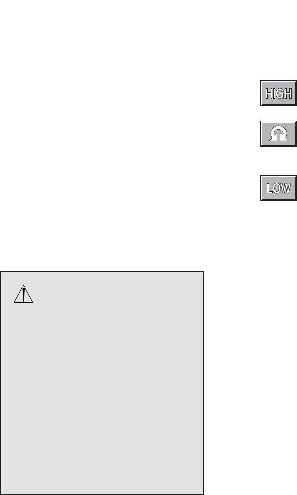
High: Enables handpiece to
operate in a high speed mode.
Low: Enables handpiece to
operate in a low speed mode.
Toggle Buttons
NOTE: For easy identification, only toggle
buttons have a white background.
Speed: Use with the increase
and decrease icons to adjust
rotary handpiece speed.
Water: Use with the increase
and decrease icons to adjust
irrigation flow.
Power: Use with the increase
and decrease icons to adjust
saw power.
Variable: Handpiece speed
responds to varying degrees of
pressure on the footswitch or
handswitch.
Nonvariable: Handpiece
operates at constant set-point
speed/power level.
One touch: Handpiece is
activated by one touch of a
trigger device and continues to
run when the trigger device is
released. Handpiece is
deactivated by touching any
trigger device. In this mode, the
handpiece operates at constant
set-point speed/power level.
Footswitch Icon: Appears
when a footswitch is connected
to the console. Also gives
access to footswitch adjust-
ments screen.
Quick Reference Guide
Icon Definition
Adjustment Arrows: Use in conjunction
with other options to set handpiece
speed or power, braking, acceleration,
irrigation flow, screen contrast etc.
Increase
Decrease
Advanced: - Accesses the
advanced footswitch mapping
screen.
Button: Access button
mapping screen.
Return to full screen: Return
from Big to full handpiece
screen.
NOTE: TPS Console models REF 5100-1 and 5100-201 do
not display options related to handpiece irrigation.

12
Saw Handpiece Screen
TPS Oscillating and Sagittal Saws
POWER/WATER ADJUSTMENT
The power icon functions as a toggle
switch for power and water settings.
Power and irrigation adjustments are
made using the adjustment arrows.
As the power setting is reduced from 100%, a vertical
bar displays to correspond to the lower selected
maximum power.
The irrigation setting is not displayed on this screen.
However, it can be seen on the Handpiece Adjust-
ments screen.
METHOD OF OPERATION
Saws can be operated with the TPS Universal
Handswitch or TPS Footswitch.
Handswitch Handpiece selection can be made by
depressing the handswitch once. The handpiece
select icon changes to indicate the active handpiece.
Depress the handswitch again to run the handpiece.
Handpiece runs from start-up to the maximum
selected speed.
Footswitch Handpiece runs from start-up to the
maximum selected speed with either the forward or
reverse pedal.
This screen appears when a TPS saw is selected at the TPS1 port with the
maximum power set at 100%.
ENDO, TPS2 and the footswitch icons indicate other instruments are plugged
into the console.

13
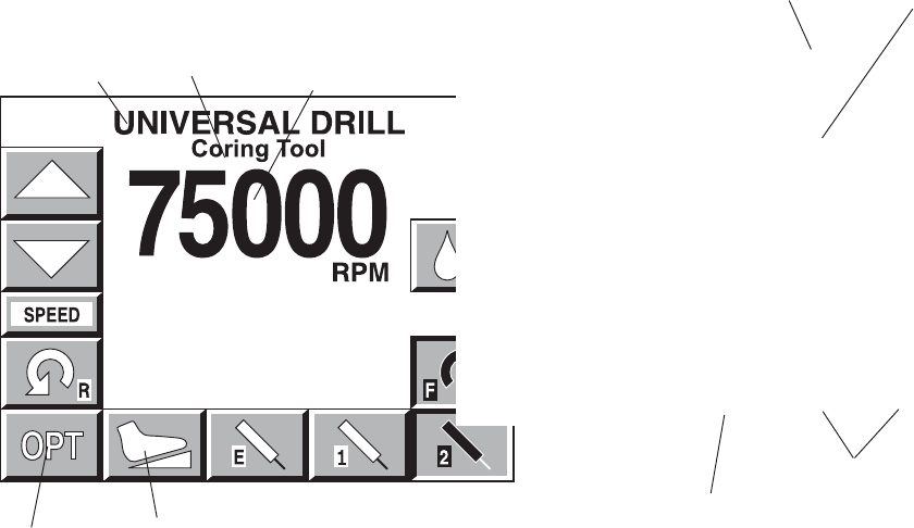
Rotary Handpiece Screen
This screen appears when a TPS rotary handpiece is selected. The TPS Universal
Drill is plugged into the TPS2 port and the speed is set at 75,000 RPM.
ENDO, TPS1 and the footswitch icons indicate that other instruments are plugged
into the console.
SPEED/WATER ADJUSTMENT
The speed icon functions as a toggle
switch for speed and water settings.
Speed and irrigation adjustments are
made using the adjustment arrows.
DIRECTION OPTIONS
FORWARD Clockwise
REVERSE Counterclockwise
OSCILLATE
TPS MicroDriver and Universal
Driver
METHOD OF OPERATION
The TPS MicroDriver can be operated with its built-
in trigger and rotary control switch or with the TPS
Footswitch.
NOTE: The handpiece will not run when the rotary
switch is in the SAFE position.
Trigger The built-in speed control trigger(s) runs
the handpiece from start-up to the maximum
selected speed.
MicroDriver only: Select cutting direction with the
rotary switch on the handpiece. Direction icon will
highlight to match the rotary switch position.
Universal Driver only: Select cutting direction by
depressing either the forward trigger or the reverse
trigger. Squeezing both triggers simultaneously
runs the handpiece in the oscillate mode. The
oscillate icon will become highlighted.
Footswitch Handpiece runs from start-up to the
maximum selected speed.
The direction icon on the screen changes when the
corresponding footswitch pedal is depressed.
Footswitch operation overrides handpiece settings.
Example: If the footswitch reverse pedal is de-
pressed while the handpiece rotary switch is set in
forward, the handpiece operates in the reverse
direction and the reverse icon highlights. However,
after the pedal is released, the direction icon will
revert to the direction set on the rotary switch.
TPS Universal and Micro Drills
METHOD OF OPERATION
The Universal Drill can be operated with the TPS Universal
Handswitch or TPS Footswitch.
Handswitch Handpiece selection can be made by depress-
ing the handswitch once. The handpiece select icon changes
to indicate the active handpiece. Depress the handswitch
again to run the handpiece.
Handpiece runs from start-up to the maximum selected
speed. Speed and cutting direction corresponds to what is
selected on the screen.
Footswitch Handpiece runs from start-up to the maximum
selected speed.
Handpiece direction is controlled by selecting the forward or
reverse pedals. The direction icon on the screen changes
when the corresponding footswitch pedal is depressed.
14
Depress the mode icon and set the maximum speed
using the adjustment arrows. Speed settings are
individually selected for each mode.
Default speed settings and incremental steps are
specific to each handpiece.
MODES
Operation in high speed mode.
Operation in oscillate mode.
Operation in low speed mode.
The Stryker Endoscopy and Leibinger Handpiece Screen
The oscillate mode is selected and Set Speed is set at 1,800 RPM.
TPS1, TPS2 and the footswitch icons indicate that other instruments are plugged
into the console.
WARNING: Read and understand
the Stryker Endoscopy handpiece
instructions.
If instructions were not supplied with your
handpiece, refer to the appropriate Stryker
Endoscopy Operating and Maintenance
Manual listed below.
Handpiece Manual
272-704 1000-400-120
275-701 1000-400-034
275-705 1000-400-034
275-601 1000-400-034
290-601 1000-400-288
IMPORTANT INFORMATION
The hand-controlled Endo Shaver can be
controlled by the footswitch or by the hand-
control buttons built into the handpiece.
15
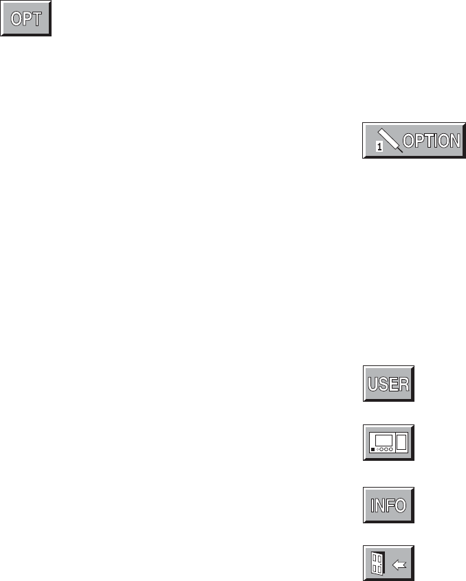
Main Option Screen
Select the OPT icon to access the MAIN OPTION
screen. This screen allows direct access to the
handpieces attached to the console, console and user
settings, and system information.
OPTION 1, 2, and E icons appear only when hand-
pieces are plugged into the corresponding console
ports. A handpiece must be plugged in to program its
settings.
To go to the HANDPIECE ADJUSTMENT screen, touch
the option button that corresponds to the desired
handpiece. Refer to HANDPIECE ADJUSTMENT.
The MAIN OPTION screen also gives DIRECT
access to:
Refer to SURGEON PREFERENCE.
Refer to CONSOLE ADJUSTMENT.
Refer to SYSTEM INFORMATION.
EXIT: Return to handpiece screen.
16
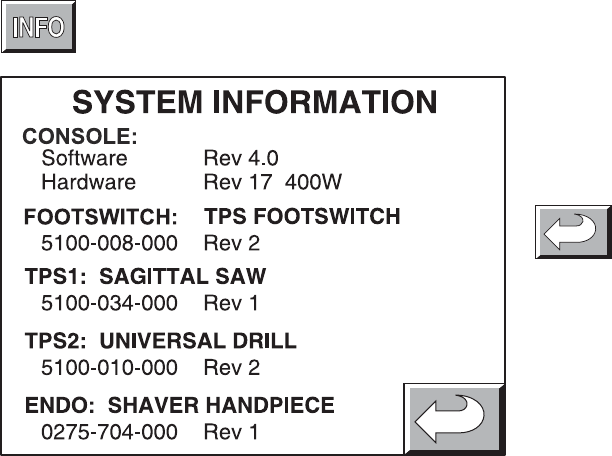
System Information Screen
Selecting the INFO icon from the MAIN OPTION menu
displays the part numbers and revision levels of the
configured system components.
This information is used as a diagnostic aid only.
Return to the MAIN OPTION screen.
17
Handpiece Adjustment Screen
Select a Handpiece Option icon from the MAIN OPTION
screen to access this screen.
NOTE: For quick access to this screen, touch the
handpiece title displayed at the top of any handpiece
screen. And return to the handpiece screen by
touching the handpiece title displayed on this screen.
Depending on the type of handpiece, one or more of
the following options will be available.
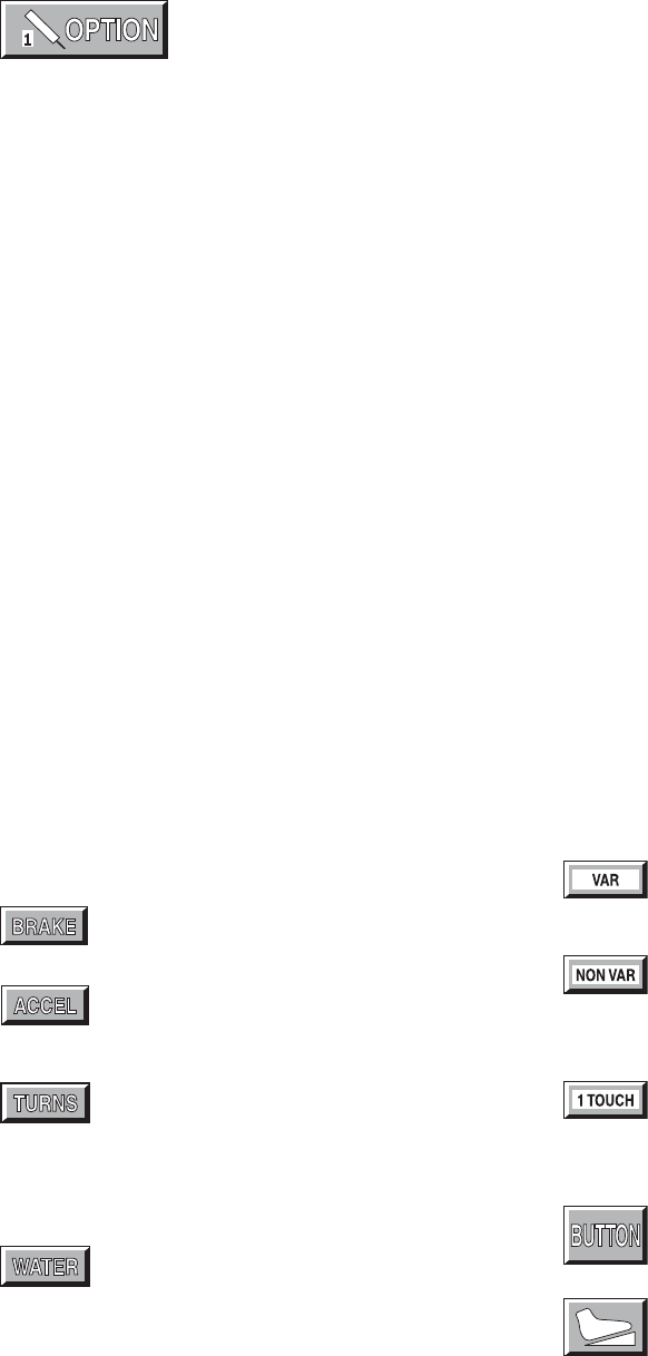
Select BRAKE, ACCEL, TURNS, WATER or AUX then
press the arrow icons to change the setting.
Brake: At 100%, the handpiece stops abruptly.
Deceleration slows as the setting nears zero.
Accelerate: At 100%, handpiece speed
accelerates quickly. Acceleration slows as the
setting approaches zero.
Turns: Use to set the number of turns per
direction when running a handpiece in the
oscillate mode. The minimum setting will set
the oscillate function to operate in a TIME-
BASED mode where the number of turns are
based on the speed of the handpiece.
Water: At 100%, irrigation volume is greatest.
Volume decreases as the setting approaches
zero.
ATTACHMENT: Use the arrow icon on the left to scroll
through the list of attachments. Select the attachment that
is assembled to the handpiece by stopping on it.
Selecting the proper attachment will optimize the perfor-
mance of the handpiece for the attachment and display
the appropriate speed scale on the handpiece screen.
RUN MODE: Use the RUN MODE toggle button to
scroll through the options and stop on the desired
setting.
Variable: Handpiece speed responds to the
degree of pressure applied to the handswitch.
Nonvariable: Handpiece speed runs at the
maximum setting only. Varying pressure on
the handswitch does not vary the handpiece
speed.
One touch: Toggle the handpiece on and off
with a single touch of a trigger device. The
trigger device can be the handswitch or
handpiece trigger buttons.
BUTTON: See Handpiece Button Mapping.
FOOTSWITCH: Activates FOOTSWITCH
ADJUSTMENTS. See Footswitch Adjust-
ments.
18
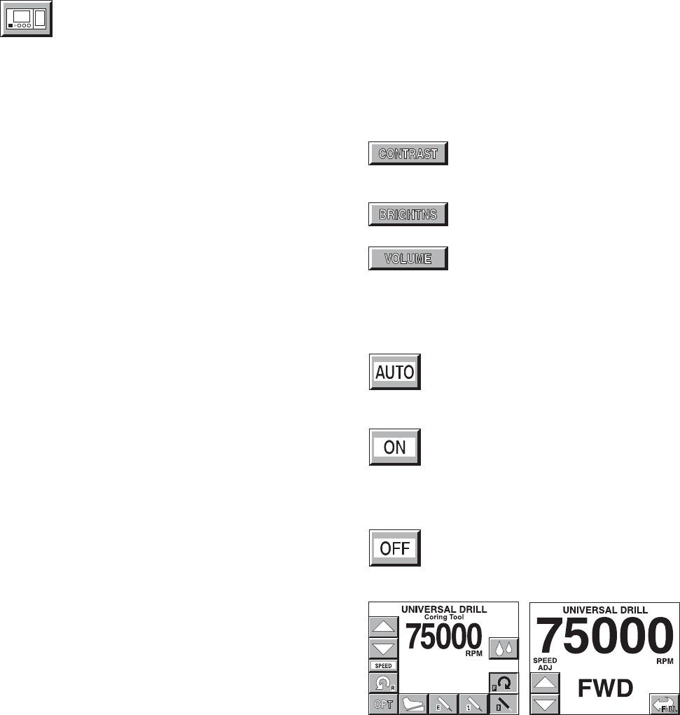
Console Adjustment Screen
Select the CONSOLE ADJUSTMENTS icon from the
MAIN OPTION screen to access this screen.
Select CONTRAST, BRIGHTNESS or VOLUME then
press the arrow icons to change the setting.
Contrast: Screen contrast lightens at
higher settings. The chosen setting
remains until reset.
Brightness: Screen brightness
intensifies at higher settings.
Volume: The audible signal is louder at
higher settings.
Use the BIG SCREEN toggle button to select one of
the following options.
Automatic: A big screen is displayed while
the handpiece is running and automatically
returns to the full screen when handpiece
stops.
On: The big screen is continuously dis-
played. It can be temporarily switched back
to the full screen by touching the Full Screen
icon which appears in the lower right corner
of each handpiece screen. See example of
screens below.
Off: The big screen option is turned off.
Only a full screen is displayed.
Example of big screen.
Example of full screen.
19
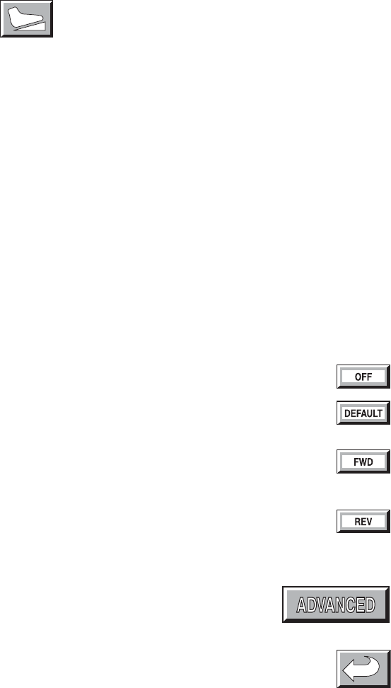
This screen appears only when using a TPS Footswitch
that is Revision 3 or newer. See Standard Features.
NOTE: The Footswitch revision is displayed on the SYSTEM
INFORMATION screen.
Access this screen by selecting the Footswitch icon on the
HANDPIECE CONTROL SCREEN or HANDPIECE ADJUST-
MENTS screen.
NOTE: These footswitch settings function only for the
handpiece for which they were selected. The handpiece is
identified at the top of the screen.
From this screen, the default functions of footswitch pads A
and B can be reprogrammed to accommodate the surgeon's
preferences. The left and right toggle icons correspond
respectively to footswitch pads A and B. Press each icon to
scroll through the following function options and stop on the
desired setting.
Off: Pedal is turned off.
Default: Footswitch defaults to the settings
selected on the handpiece screen.
Forward: Pedal setting default is overridden.
Pedal will provide handpiece rotation in the forward
(clockwise) direction.
Reverse: Pedal setting default is overridden.
Pedal will provide handpiece rotation in the reverse
(counterclockwise) direction.
Advanced: Use to access the Footswitch Button
Mapping screen. It will allow you to reprogram all
the footswitch pedals.
Return: Return to the previous screen.
Footswitch Adjustment Screen
20
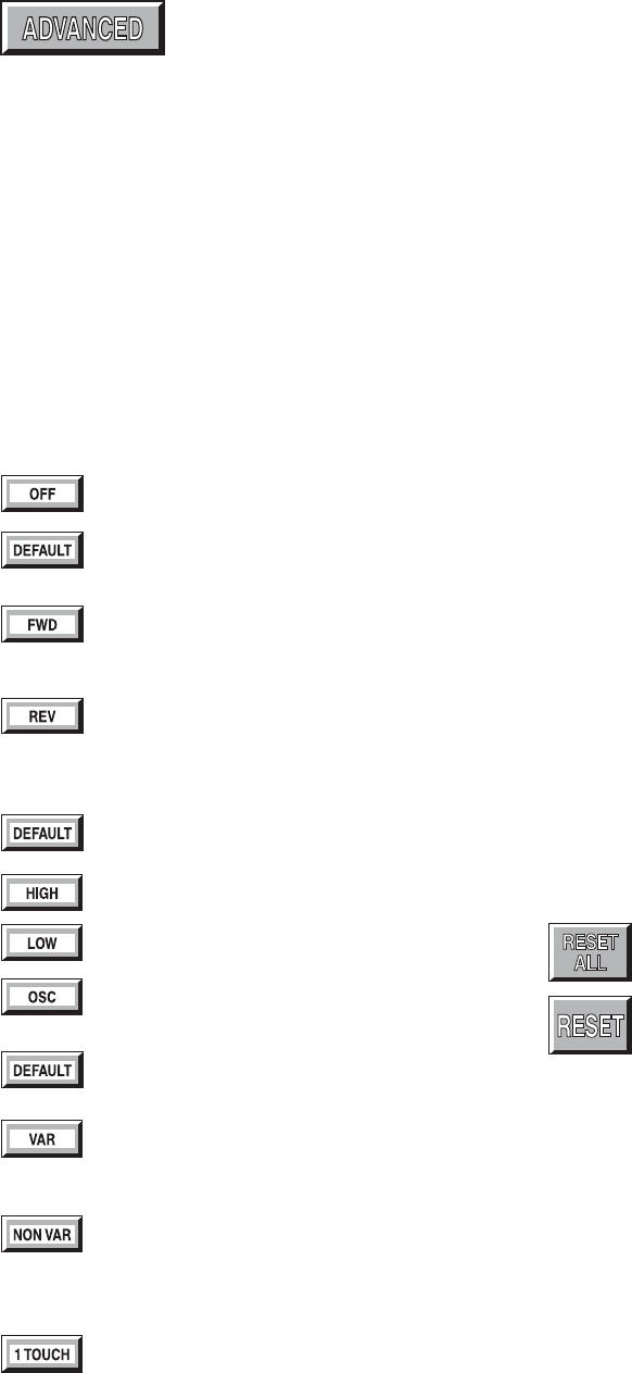
Footswitch Button Mapping Screen
Access this screen by selecting the ADVANCED icon on
the FOOTSWITCH ADJUSTMENTS screen. The default
functions of each footswitch pedal and button can be
reprogrammed to accommodate the surgeon's prefer-
ences.
Depending on the type of handpiece displayed at the top
of the screen, one or more of the following options will be
available on this screen.
The DIRECTION, OP MODE, and RUN MODE icons
correspond respectively to the two largest footswitch
pedals. Press each icon to scroll through the follow-
ing function options. And stop on the desired func-
tion setting.
DIRECTION
Pedal is turned off.
Footswitch defaults to the settings selected on
the handpiece screen.
Forward: Pedal setting default is overridden.
Pedal will provide handpiece rotation in the
forward (clockwise) direction.
Reverse: Pedal setting default is overridden.
Pedal will provide handpiece rotation in the
reverse (counterclockwise) direction.
OP MODE
Footswitch defaults to the settings selected on
the handpiece screen.
Handpiece operates in the high speed range.
Handpiece operates in the low speed range.
Handpiece operates in oscillate mode.
RUN MODE
Footswitch defaults to the settings selected on
the handpiece adjust screen.
Variable: Variable speed control. Speed
responds to varying degrees of pressure on the
footswitch.
Nonvariable: Handpiece operates at a
constant speed level determined by the
maximum speed selected from the handpiece
screen.
One touch: The one touch function is similar to
an on/off toggle. Tap the footswitch to operate
the handpiece at the maximum speed selected
from the handpiece screen. Tap any trigger
device again to stop operation.
BUTTON FUNCTION
The I, II, and III icons correspond to the three small pads
across the top of the footswitch.
Button Function displays the active function of the
corresponding button.
Use the arrow icons to scroll through the functions and
stop on the desired setting.
See Button Functions listed on next page.
Reset all: Press to return all pedals and
buttons back to their default setting.
Reset: Press to return the selected footswitch
button back to its default setting.
21
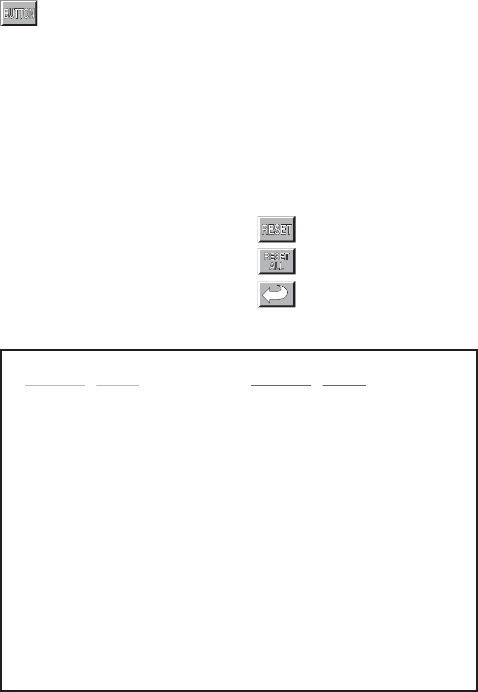
Handpiece Button Mapping Screen
Access this screen from the Handpiece Adjustment
screen. Use it to change handpiece button func-
tions.
Depending on the features of the handpiece, as
many as five buttons can be reprogrammed. Identify
corresponding button numbers by pressing the buttons
on the handpiece. When the handpiece button is
selected, the corresponding function is displayed on the
screen. Use the arrow icons to scroll through the
function options. Stop on the desired option. See the
list below for a description of the options.
NOTE: Available options are handpiece specific.
BUTTON FUNCTIONS
Reset: Select to return a single button to its
default function.
Reset all: Select to return all buttons to their
default functions.
Return: Return to previous screen.
Button Function Description
Main trigger Starts handpiece in default direction
and mode.
FWD trigger Starts handpiece in forward
direction in default mode.
REV trigger Starts handpiece in reverse
direction in default mode.
OSC trigger Starts handpiece in oscillate mode.
Speed increment Increments the set point speed.
Speed decrement Decrements the set point speed.
Water increment Increments the pump flow set point.
Water decrement Decrements the pump flow set
point.
Water on/off Toggles the pump on/off button. If
pressed and held, the pump can be
turned on without running the
handpiece. Once started, the pump
can be stopped by pressing the
button again or by starting the
handpiece.
Button Function Description
Osc <> High/low Toggles the run mode between oscillate
and high or low.
High <> Low Toggles the run mode between high and
low.
Forward <> Reverse Toggles the running direction.
Change port Changes the active handpiece port.
Change attachment Scrolls through the attachment list for the
selected handpiece.
Pump flush Turns the pump on at the flush rate. Once
started the pump can be stopped by
pressing the button again or by starting
the handpiece.
Make port active Makes the selected handpiece active.
Button Functions List

22
Surgeon Preference Screen
Access the SURGEON PREFERENCE screen from the MAIN
OPTIONS screen.
The console is able to capture and store the preferred settings of
different surgeon's.
There are three options:
• Factory default settings
• Settings saved by a previous surgeon
• Collection and storage of new settings
Using factory settings
1. Use the arrows to obtain "Stryker" and "Factory Default."
NOTE: The EDIT, DELETE and padlock icons do not function
while factory default settings are selected.
Using the settings saved by a previous user
1. Use the arrows to select the surgeon and procedure.
2. Select LOAD. Screen returns to the MAIN OPTION screen.
3. Proceed with surgery.
Collect and store preferred settings
1. Select NEW. The editor screen will appear with the selected
surgeon's name.
2. To create a new procedure under this surgeons name, select
ENTER. Or if you wish to collect and store settings under a
new surgeon name, use the key pad to delete (DEL) the
existing name then key-in the new name. Upon completion,
select ENTER.
3. Use the key pad to enter the procedure name.
4. Upon completion, select ENTER. The screen returns to the
SURGEON PREFERENCE screen.
5. Toggle padlock icon so that the padlock appears open.
6. Select LOAD.
7. Configure system settings.
8. Upon completion, return to the SURGEON PREFERENCE
screen.
9. Toggle the padlock icon so that the padlock appears locked.
NOTE: If the padlock icon remains in the unlocked position, the
selected settings will be continuously updated with current
settings.
Select to add a surgeon name.
Select to change the doctor name and/or procedure.
NOTE: Toggle the UPPER/LOWERCASE pad on the
editor screen to select letter case.
Delete: Select to delete the currently displayed file.
Select and use with the open padlock to gather (load)
new preference settings.
Default: Using the arrows, scroll the SURGEON
PREFERENCE screen to the desired surgeon and
procedure settings before activating DEFLT. This
selection becomes the default power on setting for the
system until a different selection is made.
This is the key pad screen used to
enter the doctor's name and name
of procedure.
Padlock opened to gather preferences.
Padlock closed to store preferences.

23
Messages
Message If you select OK to this question:
Delete all the surgeon's procedures? The surgeon ID and all procedures will be deleted.
Change the name of all the surgeon's Procedures listed under the surgeon will be moved under
procedures? the current surgeon's name.
Identical record found.
Maximum number of records exceeded. Please delete inactive records.
Initializing console hardware. Please wait.
Handpiece has reached recommended service interval. Please return for service at earliest convenience.
Handpiece does not support the selected preference. Default handpiece setting will be used.
Handpiece temperature has exceeded its nominal operating range and may cause burning.
Handpiece temperature has exceeded its operating range. Allow to cool before restarting.
Procedure name unspecified.
Ensure handpiece speed does not exceed specified attachment limitations. Failure to do so may result in user and/or patient
injury.
Error Messages
Message Action to Take
Error 001. Console hardware fault detected. Return console to Stryker for repair.
Error 002. Console hardware fault detected. Turn unit off and on again. If problem persists, return
Contact your Stryker service representative. console to Stryker for repair.
Error 003. Console hardware fault detected. Turn console off and on again. If problem persists, return
Contact your Stryker service representative. console to Stryker for repair.
Error 004. Footswitch fault detected, right pedal will be disabled. Unplug Footswitch from console and plug in again.
Contact your Stryker service representative. If problem persists, return footswitch to Stryker for repair.
Error 005. Footswitch fault detected, left pedal will be disabled. Unplug Footswitch from console and plug in again.
Contact your Stryker service representative. If problem persists return footswitch to Stryker for repair.
Error 006. Footswitch unreadable. Unplug Footswitch from console and
Contact your Stryker service representative. plug in again. If problem persists,
return footswitch to Stryker for repair.
Error 007. Handpiece fault detected, handpiece triggers will be Unplug cord from handpiece and plug in again.
disabled. Contact your Stryker service representative. If problem persists, return handpiece to Stryker for repair.
Error 008. Handpiece unreadable. Unplug handpiece from console and plug in again.
Contact your Stryker service representative. If problem persists, return handpiece Stryker for repair.
Error 009. Handpiece requires additional console hardware. Call your Stryker Instruments sales representative.
Contact your Stryker service representative.
Error 010 Handpiece requires additional console hardware. Call your Stryker Instruments sales representative.
Contact your Stryker service representative.
Error 011 Handpiece requires additional console hardware. Call your Stryker Instruments sales representative.
Contact your Stryker service representative.
The Total Performance System is not field repairable. In case of operating difficulties, Stryker products must be returned for maintenance
or repair.
24
Specifications
Electrical: 100-120VAC, 50-60Hz 6.0A
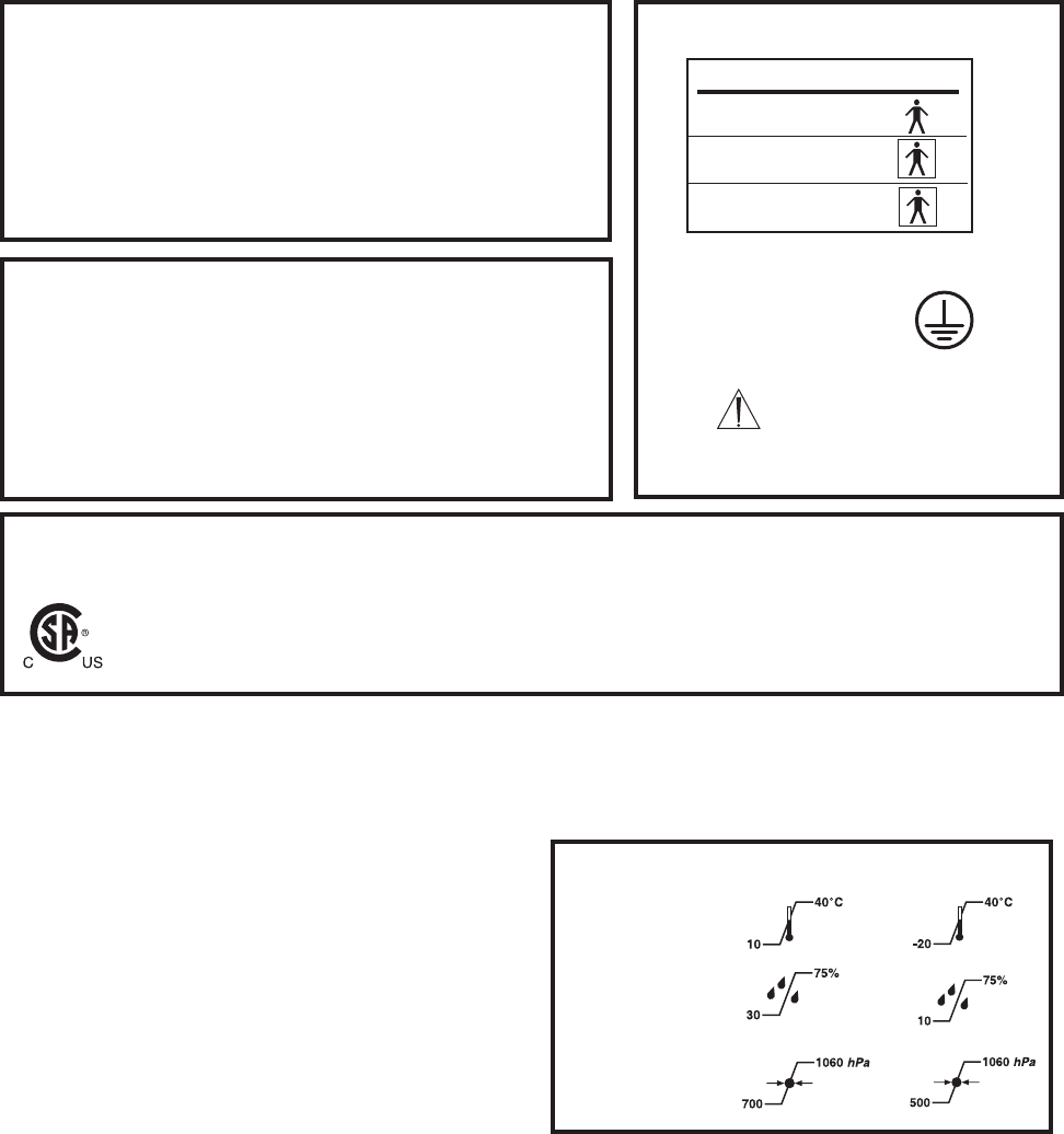
Approval: CSA International
• UL 2601-1
• CAN/CSA-C22.2 No. 601.1 M90
• IEC 60601-1
Class I
PORT TYPE SYMBOL
Endo B
TPS1 BF
TPS2 BF
IPX0 Ordinary Equipment
Protective Earth Ground
Duty Cycle: Continuous operation with
intermittent loading
Refer to cycle times defined in
the TPS handpiece instruc-
tions.
Handling your console and equipment
• When setting up your console, place on a sturdy, flat surface,
and carefully follow all setup instructions.
• When connecting or disconnecting a cable, always hold the
cable by its connector (the plug, not the cord).
• Never force a connector into a port. If the connector and port
do not join with reasonable ease, they probably don't match.
Make sure that the connector matches the port and that you
have positioned the connector correctly in relation to the port.
• To ensure the longevity, performance, and safety of this
equipment, package in original package materials when storing
or transporting.
If the console experiences sporadic electrical interference:
• Turn off all electrical equipment not in use in the operating room.
• Relocate electrical equipment; increase spacial distance.
• Plug the TPS console and other operating room equipment into
different outlets.
Environmental Conditions
These conditions apply to all components of the TPS system
unless otherwise specified in the information supplied with
that device.
Environmental Conditions: Operation Storage and Transportation
Temperature:
Relative humidity:
Atmospheric Pressure:
Specifications listed are approximate and may vary slightly from
unit to unit or by power supply fluctuations.
Models: 5100-1 TPS Console
5100-50 TPS Irrigation Console
Size: 11.8 in. [299 mm] width
7.0 in. [179 mm] height
9.0 in. [229 mm] depth
12.2 in. [310 mm] depth (units with irrigation pump)
Weight: 9 lbs. [4.1 Kg]
14.1 lbs. [6.4 Kg] (units with irrigation pump)
Models: 5100-201 TPS Hermes READY™ Console
5100-250 TPS Hermes READY™ Irrigation Console
Size: 11.8 in. [299 mm] width
7.0 in. [179 mm] height
9.4 in. [240 mm] depth
12.7 in. [322 mm] depth (units with irrigation pump)
Weight: 9 lbs. [4.1 Kg]
14.1 lbs. [6.4 Kg] (units with irrigation pump)
Federal Communications Commission
Compliance Statement (US only.) FCC ID: Q9R-5100
This device complies with Part 15 of the FCC Rules. Operation is subject to the following two conditions: (1) this device
may not cause harmful interference, and (2) this device must accept any interference received, including interference that
may cause undesired operation.
Note that FCC regulations provide that changes or modifications not expressly approved by Stryker
Instruments could void your authority to operate this equipment.
25
Repair and Loaner Program
This service is available in the United States only. Outside the U.S.A., contact your Stryker sales
representative or your nearest subsidiary listed on the last page.
On request, Stryker Instruments will provide a loaner unit for your use while repairs are
being made.
Please clean and sterilize all potentially contaminated products being sent in for repair,
credit, or return of a loaner unit. The policy of Stryker Instruments is not to accept or
process potentially contaminated products which do not meet this requirement.
Also, please be aware that it is unlawful to transport bio-contaminated products through
interstate commerce which are not properly packaged and labeled as such.
1. Contact Stryker Customer Service at 1-800-253-3210 to request a loaner. Provide a
name and address for shipping. Every effort will be made to send a loaner unit immediately.
2. Send the inoperative unit to Stryker with a purchase order number of authorization for
repair. The order should explain the nature of the difficulty. Also, provide a name and
address for shipping the repaired instruments.
Return the inoperative unit to: Stryker Instruments
Repair Department
4100 E. Milham
Kalamazoo, Michigan, 49001.
3. The repaired unit will be shipped back and the repair invoice will follow under separate
cover. Under most conditions, repair turnaround time will be approximately 2-3 weeks.
4. As soon as your repaired unit is returned, return the loaner to Stryker Instruments.
Limited Warranty
For all TPS products unless otherwise specified.
In the U.S.A. only, products of Stryker Instruments are warranted to the original purchaser for a period of one
year from the date of purchase, with exceptions noted below. Products are warranted to be free from defects in
material and workmanship. Abnormal wear and tear or damage caused by misuse or by failure to perform
normal and routine maintenance as set out in the Maintenance Manual or Operating Instructions, or as demon-
strated by an authorized Stryker Instruments representative, is not covered by the warranty. Any effort at field
repair or adjustment may invalidate your warranty.
The warranty extends to all purchasers and is limited to the repair or replacement of the product without charge
when returned prepaid to Stryker Instruments. There are no other expressed warranties. This warranty gives
you specific legal rights and you may have other rights which vary by state and municipality.
For selected products.
•Universal Handswitch is warranted for a period of 6 months from date of invoice.
•Handpiece cords are warranted for a period of 6 months from date of invoice.
• Cutting accessories are not warranted.
26
Stryker International Subsidiaries
Stryker SA Phone: 41-21-963-87-01
European Headquarters Fax: 41-21-963-87-00
Cite-Centre, Grand-Rue 92
CH-1820 Montreux, Switzerland
Stryker BV Phone: 31-40-292-2522
Postbus 8747 Fax: 31-40-292-2555
5605 LS Eindhoven
The Netherlands
Stryker Corp.- U.K.Branch Phone: 44-163-52-62400
Medway House Fax: 44-163-55-80300
5000 Newbury Business Park
London Road, Newbury
Berkshire, U.K. RG14 2ST
Stryker Deutschland GmbH Phone: 49-20899-9060
Gewerbeallee 18 Fax: 49-208999-0666
D-45478 Mulheim an der Ruhr
Germany
Stryker Polska Sp. Zo.o Phone: 48-22-631-20-13
ul. Kolejowa 10/21 Fax: 48-22-631-20-15
01-217 Warsawa, Poland
Stryker Finland Phone: 358-9-477-3400
Nuijamiestentie 5B, Fax: 011-358-9-477-3344
Fin-00400
Helsinki, Finland
Stryker France SARL Phone: 33-1-48-17-50-00
BP 50040-95946 Roissy CDG Fax: 33-1-48632175
France
Dimso Iberica SA Phone: 34-1323-1731
Calle Puente Cesures Fax: 34-1315-2782
1 Bajos 28020 Madrid
Stryker Portugal, Produtos Medicos, Lda. Phone: 351-1-839 49 10
Avenida Marechal Gomes da Costa, 35 Fax: 351-1-839 49 19
1 800-255 Lisbon Portugal
Stryker Italy SrL Phone: 39-06-330541
Via Ghisalba, 158 Fax: 39-06-33625826
00188 Rome
Italy
Stryker South Africa Phone: 27-11-888-4841
195 DF Malan Drive Fax: 27-11-782-4080
2195 Northcliff
Johannesburg, South Africa
Stryker C.I.S. Phone: 7-095-917 3484
Pokerovka Str 42/5 Fax: 7-095-97 3484
3rd Floor
103062 Moscow, Russia
Stryker China, Limited Phone: 852-814-7463
10/F., Sungib Industrial Centre FAX: 852-873-0210
53 Wong Chuk Hang Road
Aberdeen, Hong Kong
Stryker Australia Pty. Ltd. Phone: 61-29-439-5100
Unit 20/39 Herbert St. Fax: 61-29-439-6400
St. Leonards NSW 2065
PO Box 50
Australia
Stryker Beijing Liaison Office Phone: 86-1-831-3388
Room 2037, Xiyuan Hotel Extension: 2037
Beijing, China Fax: 86-1-831-4577
Extension: 2037
Stryker Far East Inc., India Phone: 91-11-686-25677
1st floor 94 Uday Park Fax: 91-11-651-5496
New Delhi 110 049 India
Stryker Far East Inc., Singapore Phone: 65-287-8851
Block 204, #04-103 65-287-8353
Hougang Street 21 Fax: 65-382-3920
Singapore 1953
Stryker Far East Inc., Taiwan Phone: 886-2-2322-2895
5F-1, 23 Pa-Te Road Fax: 886-2-2357-8543
Section 1, Taipei, Taiwan ROC
Stryker Korea Phone: 82-2-565-7303
11F, Dongsung B/D, 158-24 Fax: 82-2-552-4156
Samsung-dong, Kangman-ku,
Seoul 135-090, Korea
Stryker Malaysia Phone: 603-715-3650
No 55, Lorung Rahim Kajai 13 Fax: 603-715-5228
Taman Tun Dr. Ismail
6000 Kuala Lumpur, Malaysia
Stryker Singapore Ltd. Phone: 65-293-0119
70 Bendemeer Road Fax: 65-293-7028
#03-02 Hiap Juat House
Singapore 339940
Stryker Middle East-Africa Phone: 971-2-312-145
PO Box 26589 Fax: 971-2-313-698
Abu Dhabi, UAE
Nippon Stryker K.K. Phone: 81-6-6203-2060
4-7 Awajimachi Nichome, Chuo-ku Fax: 81-6-6202-3548
Osaka 541-0047, Japan
Stryker Korea Limited Phone: 82-2-718-2972
Room 1407, Guhsung Bldg. Fax: 82-2-718-2974
541, Dohwa-Dong, Mapo-Ku
Seoul, Korea
Stryker Americas-Middle East Phone: 269-385-2600
2725 Fairfield Road 800-726-2725
Kalamazoo, Michigan 49002 USA Fax: 269-385-1062
Mailing Address:
P.O. Box 4085
Kalamazoo, Michigan 49003-4085 USA
Stryker Chile SRL Phone:562-244-3600
Avenida Nueve Tajamar 481 Fax: 562-244-3696
Torre Norte
Piso 8 Oficina 805
Santiago, Chile
Stryker Latin America Phone: 305-821-1888
Plaza Royale, Suite 304 Fax: 305-826-0067
15600 NW 67th Ave
Miami Lakes, FL 33014
Stryker Mexico, S.A. de C.V. Phone: 525-488-0890
Montecito No. 38 Piso 12 Fax: 525-488-0891
Oficina 31, Col. Napoles
Mexico D.F. 03810
Stryker Canada - Toronto Phone: 905-332-3235
3375 North Service Road Fax: 905-332-7674
Unit C-9
Burlington, Ontario
Canada L7N3G2
Stryker Canada - Montreal Phone: 514-685-4024
72 3rd Avenue North Fax: 514-685-4024
Roxboro, Quebec
Canada H8Y 2L9

27

28
4100 E. Milham
Kalamazoo, Michigan
(USA) 49001
1-800-253-321
1-269-323-7700