Stryker Instruments 5400 TPS Core Console w/ Cutter Recognition User Manual 5400 050 700 final pmd
Stryker Instruments TPS Core Console w/ Cutter Recognition 5400 050 700 final pmd
UserManual.wiki
>
Stryker Instruments
>
5400 User Manual
Users Manual
Navigation menu
Upload a User Manual
Namespaces
Wiki Guide
HTML
PDF
Info
Views
User Manual
Discussion / Help
Navigation

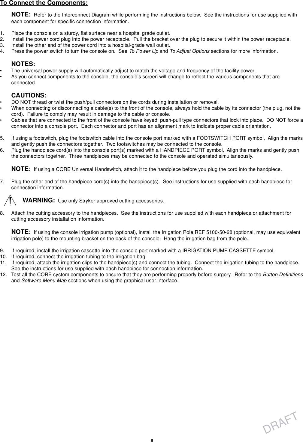
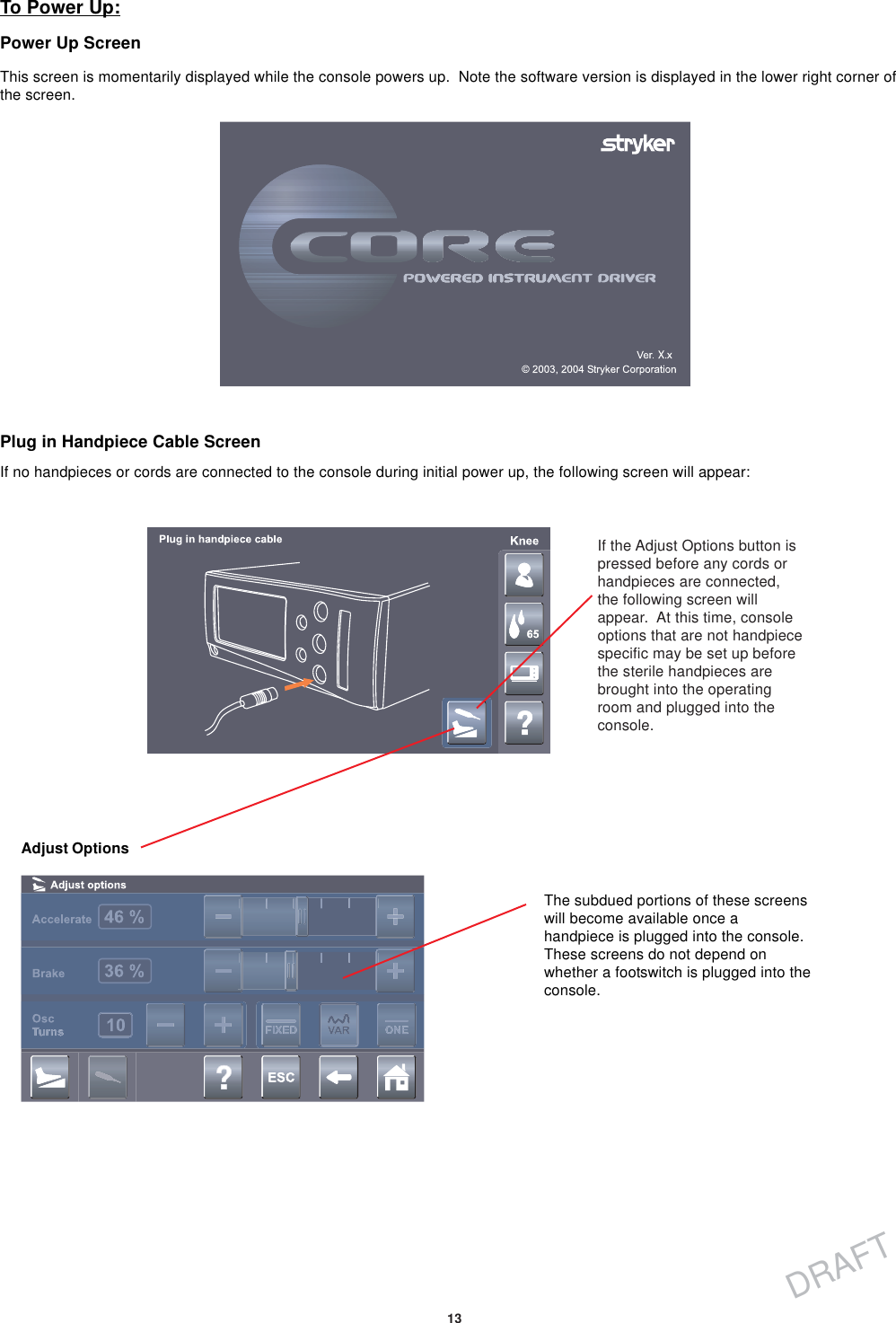
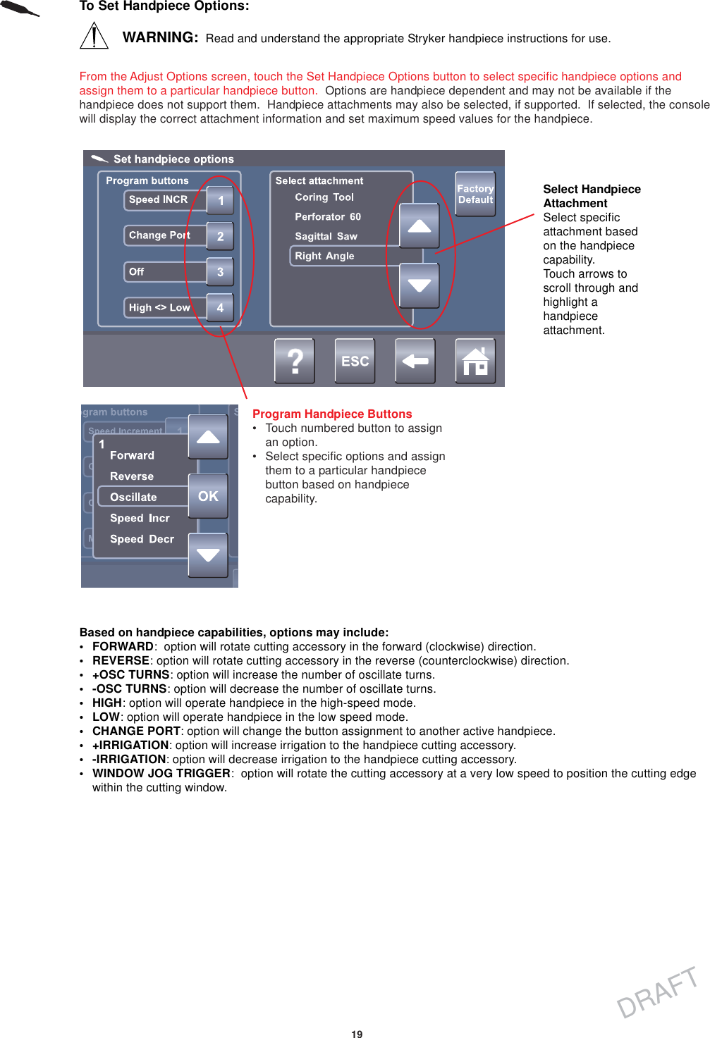
![16DRAFTTo Adjust Options:From the HOME screen, touch the Adjust Options button to adjust the handpiece and footswitch options. The availablehandpiece options will depend on the type of handpiece that is identified at the top of the screen.Adjust Acceleration• Touch the plus and minus buttons or slider bar to adjust thepercent of acceleration [0 to 100%].• At 100%, the handpiece speed accelerates quickly.Acceleration slows as the setting approaches zero percent.Adjust Braking• Touch the plusand minus buttonsor slider bar toadjust the percentof braking [0 to100%].• At 100%, thehandpiece stopsabruptly. Theamount ofdecelerationdecreases as thesettingapproaches zeropercent.Adjust Oscillate Turns• Touch the plus and minus buttons to select the number of turns per direction whenrunning a handpiece in the oscillate mode.Select Run Mode•FIXED: handpiece speed runs at the maximum settingonly. Varying pressure on the footswitch or handswitchwill not vary the handpiece speed.•VARIABLE: handpiece speed responds to the degreeof pressure applied to the footswitch or handswitch.•ONE TOUCH: Handpiece activation responds to onetouch of a trigger device(footswitch, handswitch) andcontinues to run when thetrigger device is released.Handpiece is deactivated bytouching any trigger device.In this mode, the handpieceoperates at constant set-point speed/power level.](https://usermanual.wiki/Stryker-Instruments/5400/User-Guide-472344-Page-16.png)
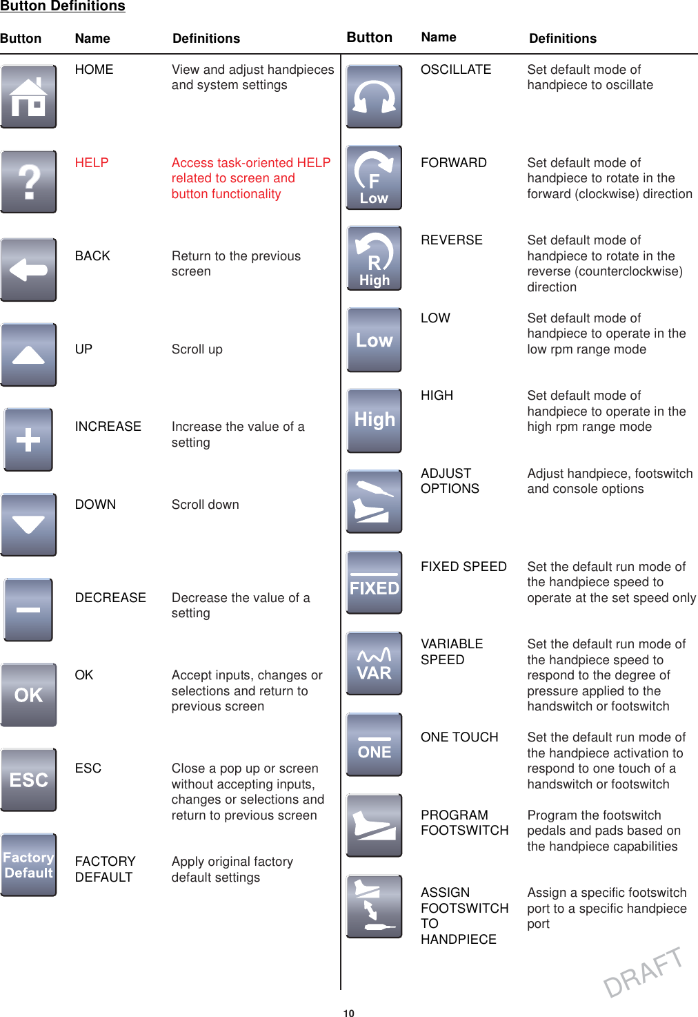
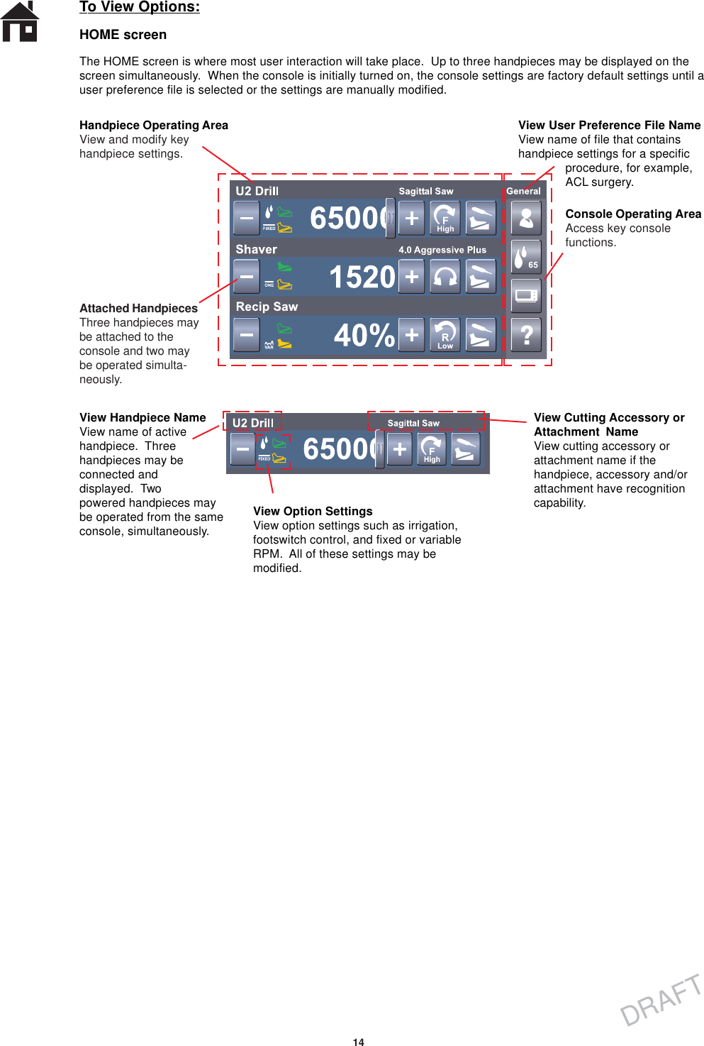
![17DRAFTTo Program Footswitch Options:From the Adjust Options screen, touch the Program Footswitch button to program the footswitch pedals and pads basedon the capabilities of the connected handpiece. Two footswitches may be connected to and simultaneously operatedfrom the same console. However, two footswitches cannot be used to control the same handpiece at the same time.Assign Specific OptionSelect a footswitch pedal or pad [A, B, I, IIor III] button and assign a specific option.View Handpiece PortIndicates the handpiece port that thefootswitch is programmed for.Based on handpiece capabilities, options may include:• FORWARD: pressure on the pad or pedal will cause thehandpiece to rotate in the forward (clockwise) direction.• REVERSE: pressure on the pad or pedal will cause thehandpiece to rotate in the reverse (counterclockwise) direction.• +OSC TURNS: pressure on the footswitch pad will cause thehandpiece to oscillate; increase number of turns.• -OSC TURNS: pressure on the footswitch pad will cause thehandpiece to oscillate; decrease number of turns.•ON: pressure on the footswitch pad or pedal will make the portactive, for example it will provide input to the assignedhandpiece.• OFF: pressure on the footswitch pad or pedal will make theport inactive, for example it will not provide input to theassigned handpiece.• HIGH: pressure on the footswitch pad will cause the handpieceto operate in the high-speed range or mode.• LOW: pressure on the footswitch pad will cause the handpieceto operate in the low speed range or mode.• SPEED INCREMENT: pressure on the footswitch pad willincrement the set point speed.• SPEED DECREMENT: pressure on the footswitch pad willdecrement the set point speed.• IRRIGATION INCREMENT: pressure on the footswitch willincrement the pump flow set point and increase irrigation to thehandpiece cutting accessory.• IRRIGATION DECREMENT: pressure on the footswitch willdecrement the pump flow set point and decrease irrigation tothe handpiece cutting accessory.• IRRIGATION ON/OFF: pressure on the footswitch will togglethe irrigation pump on and off. If pressed and held, theirrigation pump can be turned on without running thehandpiece. Once started, the irrigation pump can be stoppedby pressing the pad again or by starting the handpiece.• PUMP FLUSH: pressure on the footswitch will turn theirrigation pump on at the flush rate. Once started the irrigationpump may be stopped by pressing the pad again or by startingthe handpiece.• CHANGE PORT: pressure on the footswitch pad will changethe footswitch assignment to another active handpiece.• ONE TOUCH: acting like an on/off toggle, tap the footswitchpad to operate the handpiece at the maximum speed. Tap thefootswitch pad again to stop the operation.• VARIABLE: varying pressure on the footswitch pad will causethe handpiece speed to vary.• FIXED: pressure on the footswitch pad will cause thehandpiece to operate at a constant speed as set on the HOMEscreen.Touch the arrow buttons to scrollthrough the footswitch options.The available options arehandpiece specific. Touch the OKbutton to select the option.](https://usermanual.wiki/Stryker-Instruments/5400/User-Guide-472344-Page-17.png)
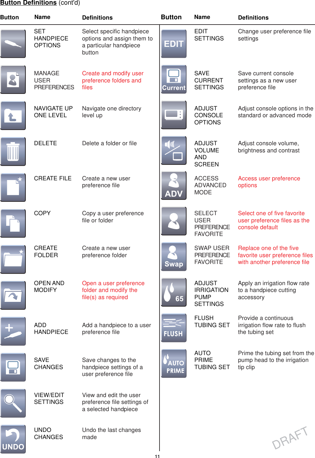
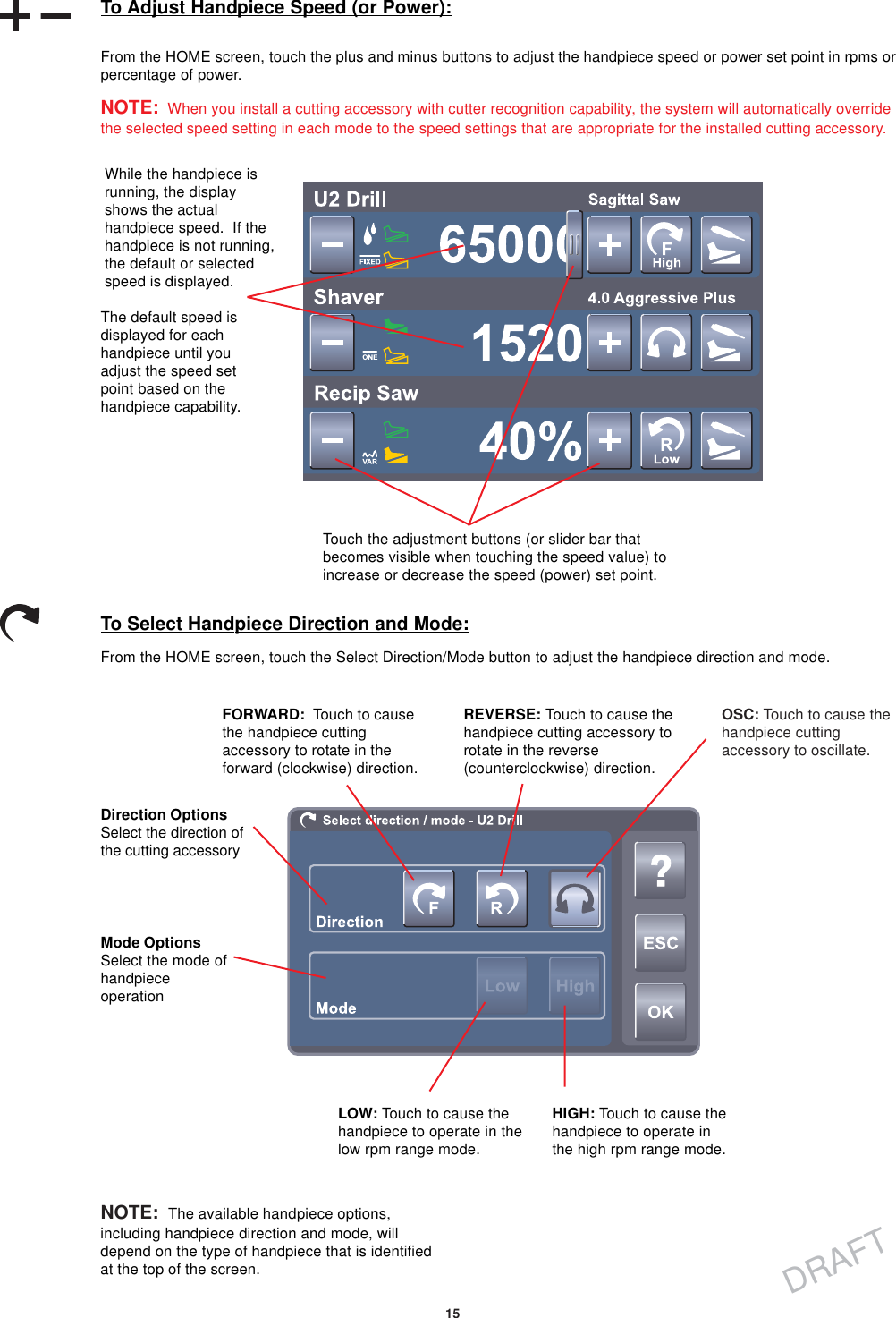
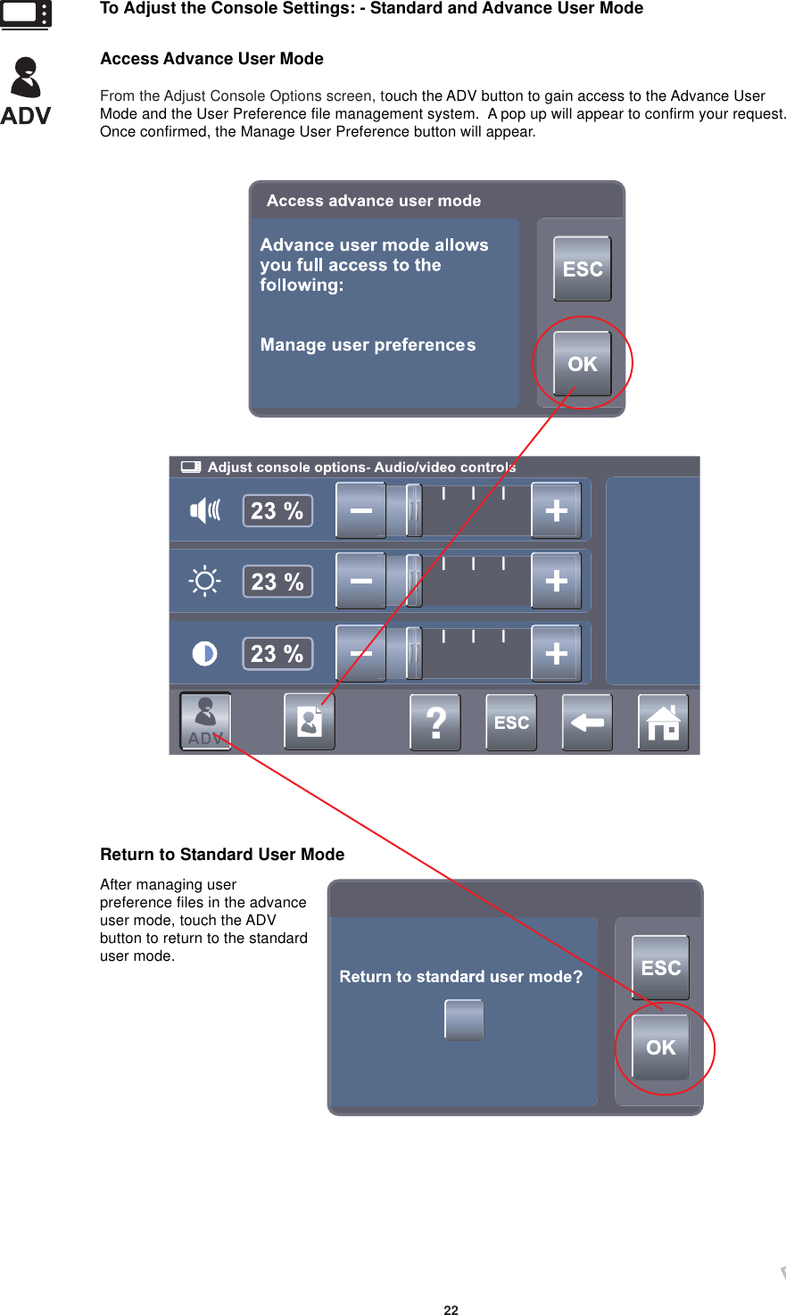
![21DRAFTTo Adjust the Console Settings: - Standard and Advance User ModeFrom the Adjust Options screen, touch the Adjust Console Options button to adjust the volume, brightness and contrast.Adjust VolumeAdjust the percent ofconsole volume [0 to 100%]by touching the slide bar orthe plus, minus buttonsAdjust ContrastAdjust the percent ofconsole display contrast [0to 100%] using the slide baror the plus, minus buttonsAdjust BrightnessAdjust the percent ofconsole display brightness[0 to 100%] using the slidebar or the plus, minusbuttonsAdjust Audio/Video Controls - Standard ModeTo Adjust Irrigation Pump Settings:NOTE: If using the irrigation pump, assemble the irrigation pole to the mounting bracket located on the back of theconsole. Hang the irrigation bag from the pole. Install the irrigation cassette into the console pump. Attach theirrigation clips onto the handpiece and connect the tubing.From the HOME screen, touch the Adjust Irrigation Pump Settings button to apply an irrigation flow rate to a handpiececutting accessory. AUTO PRIME and FLUSH options are also provided.Adjust Irrigation% Setting• Touch the slidebar or plus,minus buttons toadjust the flowrate percentageof irrigation [1 to100% or OFF] tothe cuttingaccessory of thehandpiece.• At 100%,irrigation to thehandpiece is setto maximumflow rate. The ratedecreases as thesetting approacheszero.FLUSH Tubing Set - Touch andhold to provide a continuous flowrate of 300 ml/min with no irrigationclip and a minimum pressure of 30psi when the tubing is blocked.AUTO PRIMETubing Set• Touch to activatethe primingsequence of theinstalled irrigationcassette.• The tubing will beprimed from thepump head to theirrigation tip clipwithin 20 seconds.• The button willremain depressedduring the timedoperation.Select Handpiece• Touch one or all of the handpiece buttons to allow activation of the irrigationpump. If no buttons are selected, the pump will not operate.• Activation will apply an irrigation flow rate to the handpiece cutting accessory.• The flow rate will depend on the type of handpiece.• Activating a handpiece will gain control of the console irrigation. While the firstactivated handpiece is running, activating a second or third handpiece will notchange pump flow, but may reduce irrigation to the first handpiece if a Y-splitteris used. To gain control of console irrigation using a second or third handpiece,activate the second or third handpiece while the first handpiece is not running.](https://usermanual.wiki/Stryker-Instruments/5400/User-Guide-472344-Page-21.png)
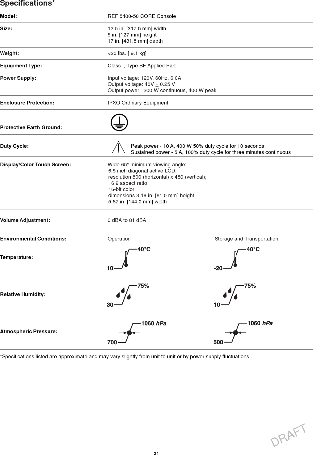
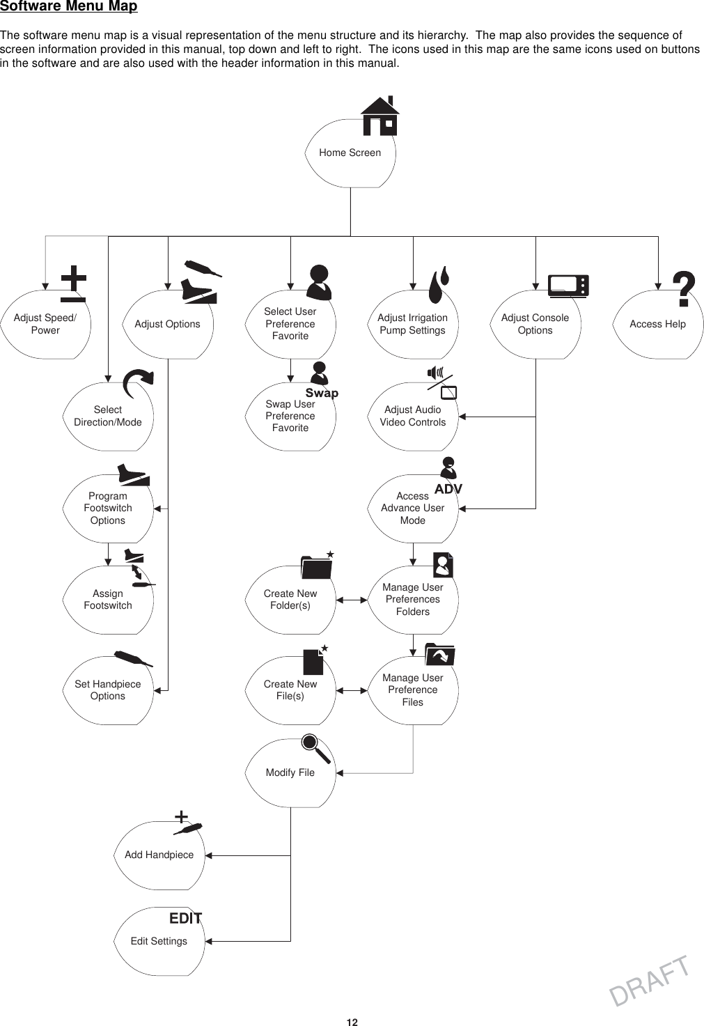
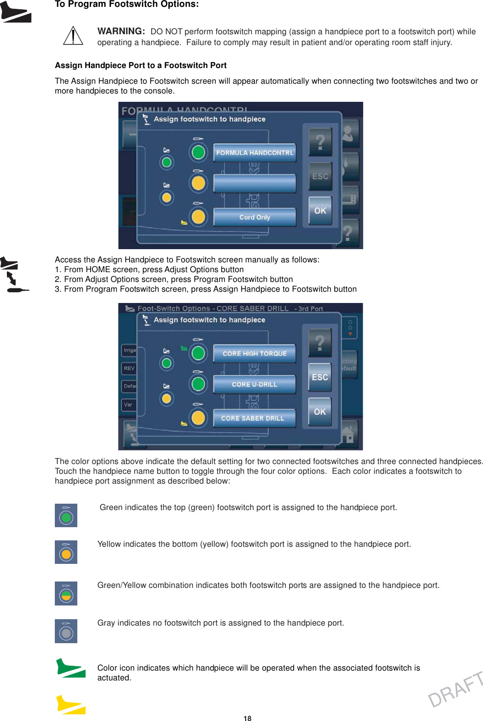
![31DRAFTModel:Size:Weight:Equipment Type:Power Supply:Enclosure Protection:Protective Earth Ground:Duty Cycle:Display/Color Touch Screen:Volume Adjustment:Environmental Conditions:Temperature:Relative Humidity:Atmospheric Pressure:Specifications*REF 5400-50 CORE Console12.5 in. [317.5 mm] width5 in. [127 mm] height17 in. [431.8 mm] depth<20 lbs. [ 9.1 kg]Class I, Type BF Applied PartInput voltage: 120V, 60Hz, 6.0AOutput voltage: 40V + 0.25 VOutput power: 200 W continuous, 400 W peakIPXO Ordinary EquipmentPeak power - 10 A, 400 W 50% duty cycle for 10 secondsSustained power - 5 A, 100% duty cycle for three minutes continuousWide 65° minimum viewing angle;6.5 inch diagonal active LCD;resolution 800 (horizontal) x 480 (vertical);16:9 aspect ratio;16-bit color;dimensions 3.19 in. [81.0 mm] height5.67 in. [144.0 mm] width0 dBA to 81 dBAOperation Storage and Transportation*Specifications listed are approximate and may vary slightly from unit to unit or by power supply fluctuations.](https://usermanual.wiki/Stryker-Instruments/5400/User-Guide-472344-Page-31.png)