Stryker Medical 6390 Power-LOAD User Manual 40f4
Stryker Medical Power-LOAD Users Manual 40f4
Contents
- 1. Users Manual 10f4
- 2. Users Manual 20f4
- 3. Users Manual 30f4
- 4. Users Manual 40f4
Users Manual 40f4
60 6390-009-001 REV B www.stryker.com
Return To Table of Contents
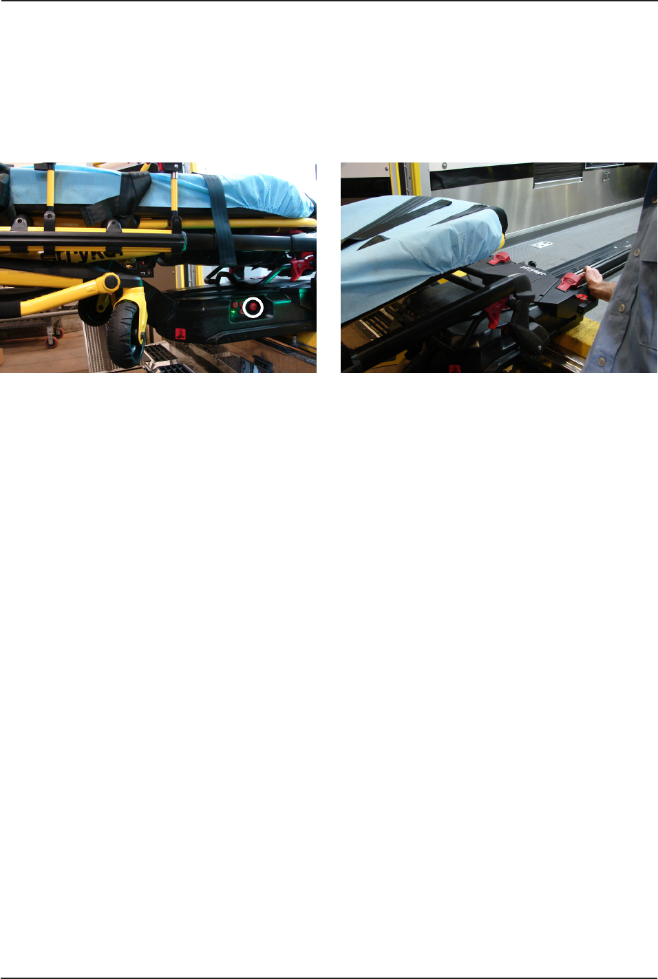
Figure 51 Figure 52
UNLOADING A COT FROM A VEHICLE MANUALLY (POWER-LOAD POWER LOSS OR SYSTEM ERROR)
(CONTINUED)
Operation Guide
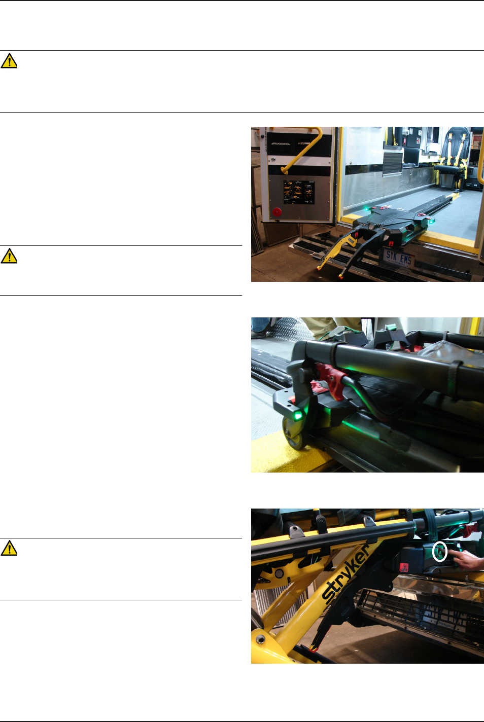
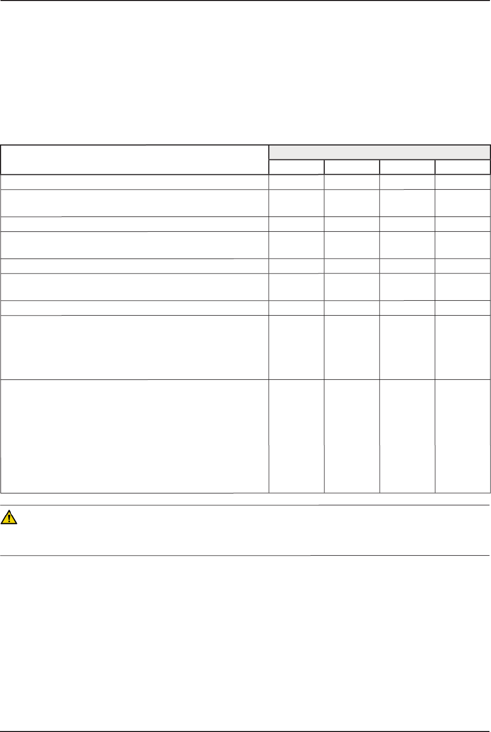
3. Press the manual release button on the Power-LOAD control panel as shown in Figure 51 to lower the lifting arms
until they are clear of the cot.
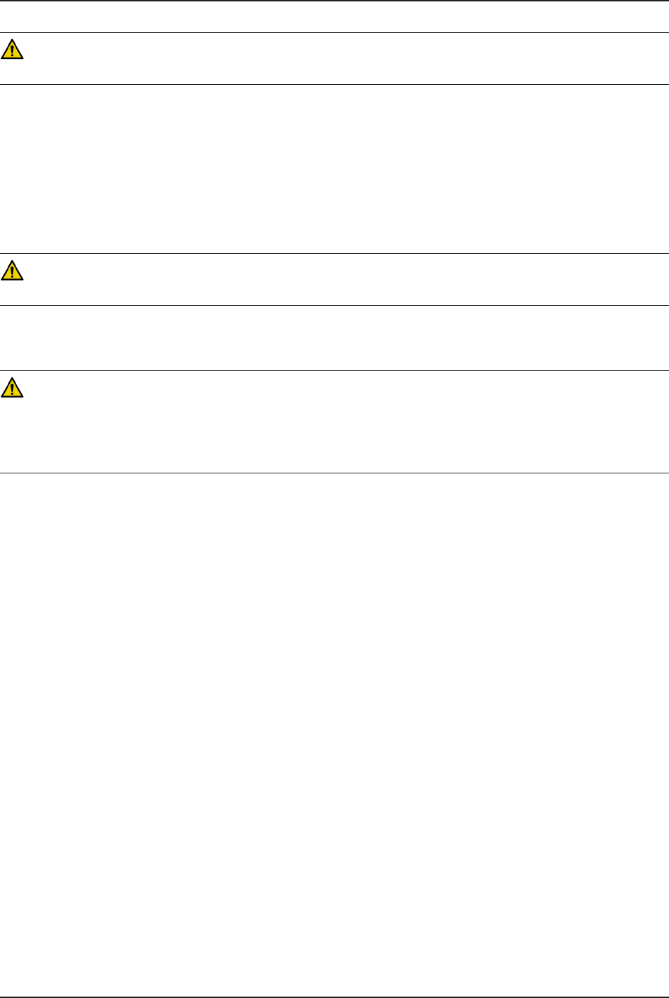
4. Lift one of the red manual cot release handles at the head end of Power-LOAD to unlock the cot as shown in
Figure 52.
5. Raise the lifting arms and guide the trolley into the vehicle patient compartment until the arms are far enough in
to not interfere with the vehicle doors.
6. Following the call, remove the vehicle from service to diagnose and repair Power-LOAD.
www.stryker.com 6390-009-001 REV B 61
Return To Table of Contents
Operation Guide
LOADING A COT INTO A VEHICLE MANUALLY (POWER-LOAD POWER LOSS OR SYSTEM ERROR)
WARNING
• Loading and/or unloading an occupied cot into a vehicle requires a minimum of two (2) trained operators.
• Make sure that all occupants enter the vehicle patient compartment after the Power-LOAD compatible cot has been
loaded into the vehicle patient compartment.
1. Lift the vehicle bumper to the raised position (if
equipped).
2. Ensure that the trolley is located at the head end of
the vehicle patient compartment with the lifting arms
down. If not, raise the lifting arms and guide the trolley
into the vehicle patient compartment until Power-LOAD
locks into position with the lifting arms down.
3. Make sure that the cot retractable head section is fully
extended and locked.
4. Place the cot in a loading position (any position
where the loading wheels meet the vehicle patient
compartment floor height).
5. Roll the cot to the open vehicle patient compartment.
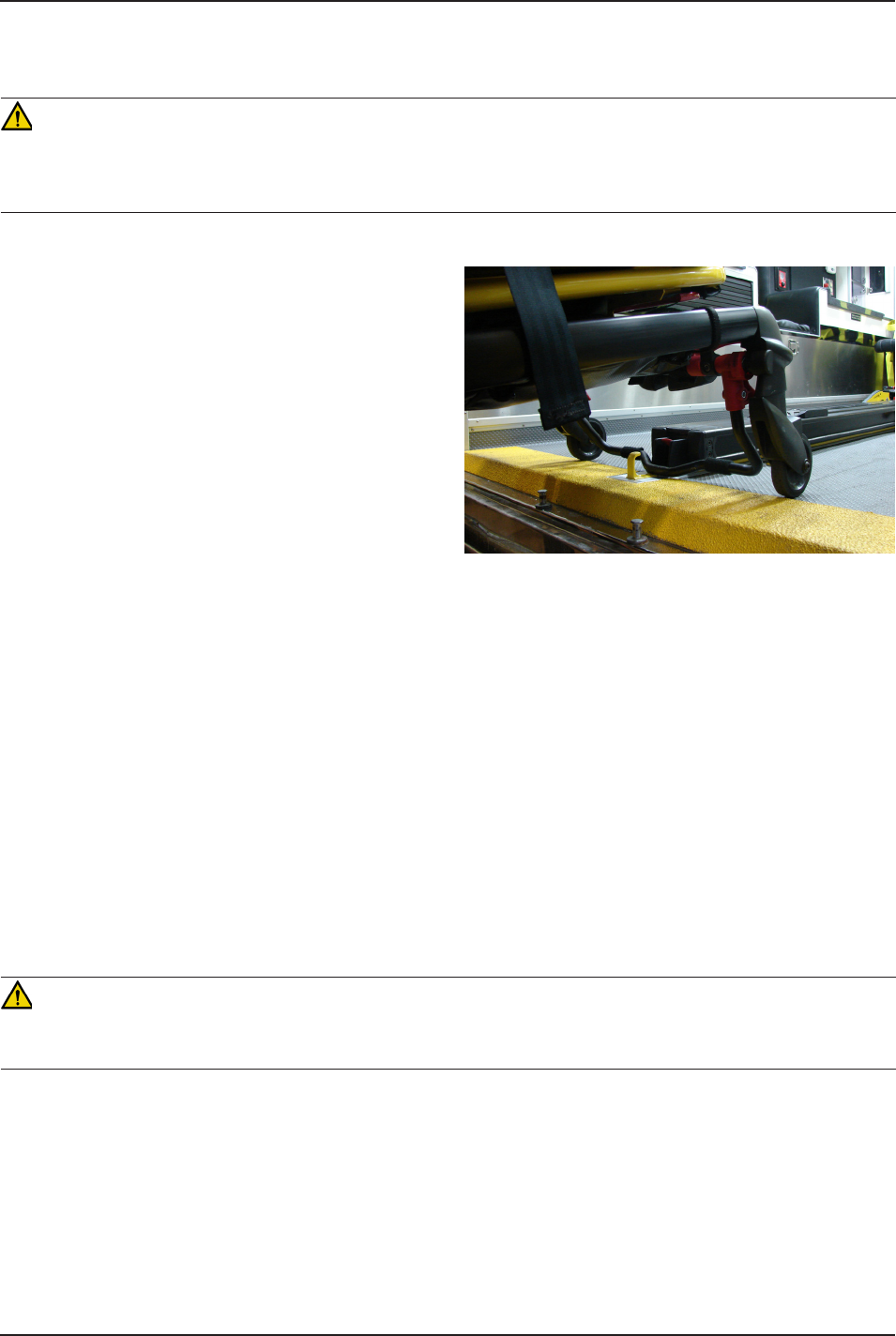
6. Push the cot forward until the loading wheels are on
the vehicle patient compartment floor and the safety
bar passes the safety hook as shown in Figure 53.
Note: For maximum clearance to lift the base, pull the
cot out until the safety bar engages the safety hook.
For models 6500/6506 and 6510/6516 with the Power-LOAD option:
• Grasp the cot frame at the foot end.
• Lift the foot end of the cot and press and hold the retract (-) button on the cot control switch to fully retract
the cot undercarriage.
Note: The cot undercarriage will retract in less than three seconds.
For models 6085/6086 with the Power-LOAD option:
• Operator 1 (Foot End) − Grasp the cot frame at the foot end. Squeeze and hold the cot manual release.
• Operator 2 (Side) − Stabilize the cot by placing one hand on the outer rail. Grasp the base frame. After the
foot end operator has lifted the cot and squeezed the cot manual release, retract the undercarriage with one
hand and hold it in place.
• Operator 1 (Foot End) - Release the cot manual release to lock the undercarriage in the retracted position.
CAUTION
To avoid the risk of equipment damage, do not push the cot into the vehicle patient compartment until the cot base is
fully retracted.
7. Push the cot into the vehicle patient compartment until the cot locks into Power-LOAD.
8. Ensure that the cot is locked into Power-LOAD by firmly pulling on the foot end of the cot.
9. Following the call, remove the vehicle from service to diagnose and repair Power-LOAD.
Figure 53
62 6390-009-001 REV B www.stryker.com
Return To Table of Contents
Operation Guide
UNLOADING A COT FROM A VEHICLE MANUALLY
WARNING
• Loading and/or unloading an occupied cot into a vehicle requires a minimum of two (2) trained operators.
• Power-LOAD is only an assisting device. Operators are responsible for evaluating each situation to determine how
to distribute and lift the weight being transported. Always use both hands when handling the cot.
• When handling weights over 400 lb (181 kg), ensure there are enough operators to handle the forces required for
loading/unloading. To increase safety, users should attempt to perform loading/unloading on flat surfaces.
1. Lift the vehicle bumper to the raised position (if
equipped).
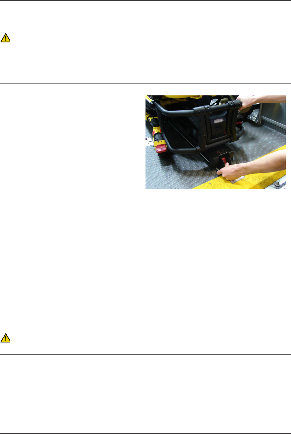
2. Press and hold the release lever at the foot end of
the Power-LOAD system and pull to remove the cot
from the vehicle patient compartment as shown in
Figure 54.
3. Grasp the cot frame at the foot end to pull the cot out
of the vehicle patient compartment.
For models 6500/6506 and 6510/6516 with the
Power-LOAD option:
• Operator 1 - Grasp the cot frame at the foot
end. While supporting the weight of the cot,
guide and pull the cot out of the vehicle patient
compartment until the safety bar engages the
safety hook. Press and hold the extend (+)
button on the cot control switch to extend the
cot undercarriage to the set load height with the
cot wheels on the ground.
• Operator 2 - Verify that the safety bar engages the safety hook and stabilize the cot during the unloading
operation by securely grasping the outer rail. Push the safety bar release lever forward to disengage the
safety bar from the safety hook in the vehicle patient compartment.
For models 6085/6086 with the Power-LOAD option:
• Operator 1 (Foot End) − Grasp the cot frame at the foot end. While supporting the weight of the cot, guide and
pull the cot out of the vehicle patient compartment until the safety bar engages the safety hook.
• Operator 2 (Side) − Grasp the base frame where indicated, lift slightly, and lower the base frame to its fully
extended position while Operator 1 squeezes and holds the cot manual release.
• Operator 1 (Foot End) − Let go of the cot manual release and ensure that the undercarriage locks into place.
Set the cot onto the ground.
• Operator 2 (Side) − Disengage the safety bar from the safety hook by pushing the safety bar release lever
forward.
WARNING
When unloading the cot, ensure that the cot wheels are on the ground before lowering the arms.
Note: In the unlikely case that the cot foot end fails and the cot cannot be removed from the vehicle, remove the patient
by alternate means (for example, by using a backboard or field cot).
Figure 54
www.stryker.com 6390-009-001 REV B 63
Return To Table of Contents
Operation Guide
REMOVING A COT FROM A VEHICLE FOR REPAIR
In the unlikely case that the cot foot end fails and the cot cannot be removed from the vehicle, remove the patient by
alternate means (for example, by using a backboard or field cot).
WARNING
Removing a cot from a vehicle for repair requires a minimum of two (2) trained operators.
1. Operator 1 - Press the manual trolley release button at the head end of the Power-LOAD system.
2. Operator 2 - Squeeze the foot end closest slide on transfer, and with the help of Operator 1, push the cot and
transfer firmly out, but not all the way out, of the vehicle compartment.
3. Operator 1 - With a screwdriver or similar tool, push on the hook assembly underneath the transfer while Operator
2 pushes the transfer forward inside of the vehicle compartment to disengage the cot from the lock.
4. After the cot is unlocked, pull the cot all the way out.
WARNING
Power-LOAD is only an assisting device. Operators are responsible for evaluating each situation to determine how to
distribute and lift the weight being transported. Always use both hands when handling the cot.
5. Ensure that the cot base is extended, then lift one of the red manual cot release handles at the head end of Power-
LOAD to unlock the cot.
WARNING
When unloading the cot, ensure that the cot wheels are on the ground before lowering the arms.
Note: In the unlikely case that the cot foot end fails and the cot cannot be removed from the vehicle, remove the patient
by alternate means (for example, by using a backboard or field cot).
64 6390-009-001 REV B www.stryker.com
Return To Table of Contents
Operation Guide
LOADING A COT INTO A VEHICLE MANUALLY (POWER-PRO POWER LOSS)
WARNING
• Loading and/or unloading an occupied cot into a vehicle requires a minimum of two (2) trained operators.
• Make sure that all occupants enter the vehicle patient compartment after the Power-LOAD compatible cot has been
loaded into the vehicle patient compartment.
1. Lift the vehicle bumper to the raised position (if
equipped).
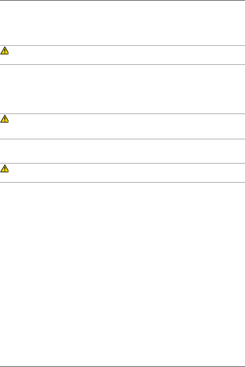
2. Raise the lifting arms to guide and pull the trolley out
of the vehicle patient compartment as shown in Figure
55.
3. Raise the cot to the load position.
4. Push the cot into Power-LOAD until the cot load wheel
pins lock into position as shown in Figure 56. Ensure
that the cot is aligned with the lifting arms when loading.
CAUTION
To avoid the risk of equipment damage, do not slam the cot
into the trolley when loading.
5. Check the head end lock LED indicators to ensure that
the cot is locked into Power-LOAD.
• If the LEDs are solid green, the cot head end is
locked into Power-LOAD.
• If the LEDs are flashing red, the cot head end is
not locked into Power-LOAD.
6. Press the up () button on the Power-LOAD control
panel as shown in Figure 57 to raise the lifting arms to
the highest position.
Note: The cot legs do not retract.
7. Operator 1 (Foot End) − Grasp the cot frame at the
foot end. Squeeze and hold the cot manual release.
8. Operator 2 (Side) − Grasp the base frame. After the
foot end operator squeezes the cot manual release,
retract the undercarriage with one hand and stabilize
the cot with your other hand.
CAUTION
To avoid the risk of equipment damage, do not push the cot
into the vehicle patient compartment until the cot base is
fully retracted.
Figure 55
Figure 56
Figure 57

www.stryker.com 6390-009-001 REV B 65
Return To Table of Contents
Operation Guide
LOADING A COT INTO A VEHICLE MANUALLY (POWER-PRO POWER LOSS) (CONTINUED)
9. Both Operators - Push the cot into the vehicle patient compartment, until the lifting arms lower and the cot locks
into Power-LOAD.
10. Operator 1 - Continue to squeeze and hold the cot manual release.
CAUTION
Do not let go of the manual release until the cot locks into position at the head end. If you let go too early, then the cot
base may prevent the cot from properly locking into Power-LOAD.
11. Ensure that the cot is locked into Power-LOAD by firmly pulling on the foot end of the cot.
12. Following the call, remove the cot from service to diagnose and repair the Power-PRO cot.
Note: Power-LOAD automatically charges the Power-PRO SMRT Pak battery when the cot is locked into Power-LOAD
in the transport position (no cable or connectors required). The cot battery LED indicator momentarily flashes green
to signify that it is charging.
66 6390-009-001 REV B www.stryker.com
Return To Table of Contents
Cleaning
WARNING
Always press the main power button to turn the unit off before service or cleaning.
CLEANING PROCEDURE
• Follow the cleaning solution manufacturer’s dilution recommendations exactly.
• Wipe the unit with a clean cloth and recommended cleaner as listed in “Cleaning” on page 67.
• Using a soft cloth and brush, clean the transfer roller channels to prevent debris accumulation according to the
Preventative Maintenance checklist on page 68.
• Towel dry the transfer roller channels and arm hinges.
WARNING
Use any appropriate personal safety equipment, such as goggles or respirators, to avoid the risk of inhaling contagion.
CLEANING LIMITATIONS
CAUTION
• DO NOT STEAM CLEAN OR ULTRASONICALLY CLEAN THE UNIT.
• Maximum water temperature should not exceed 180°F/82°C.
• Allow unit to air dry prior to use.
• Failure to comply with these instructions may invalidate any/all warranties.

www.stryker.com 6390-009-001 REV B 67
Return To Table of Contents
Cleaning
In general, when used in those concentrations recommended by the manufacturer, either phenolic type or quaternary
(excluding Virex® TB) type disinfectants can be used. Iodophor type disinfectants are not recommended for use
because staining may result.
Suggested cleaners for the Power-LOAD surfaces:
• Quaternary Cleaners (active ingredient - ammonium chloride)
• Phenolic Cleaners (active ingredient - o-phenylphenol)
• Chlorinated Bleach Solution (5.25% - less than 1 part bleach to 100 parts water)
Avoid over saturation and ensure that the product does not stay wet longer than the chemical manufacturer’s guidelines
for proper disinfecting.
WARNING
SOME CLEANING PRODUCTS ARE CORROSIVE IN NATURE AND MAY CAUSE DAMAGE TO THE PRODUCT IF USED
IMPROPERLY. If the products described above are used to clean Stryker patient care equipment, measures must be
taken to insure the units are wiped with clean water and thoroughly dried following cleaning. Failure to properly rinse and
dry the units will leave a corrosive residue on the surface of the units, possibly causing premature corrosion of critical
components.
Note: Failure to follow the above directions when using these types of cleaners may void this product’s warranty.
REMOVAL OF IODINE COMPOUNDS
Use a solution of 1/2 Tablespoon Sodium Thiosulfate in a pint of warm water to clean the stained area. Clean as soon
as possible after staining occurs. If stains are not immediately removed, allow solution to soak or stand on the surface.
Rinse surfaces which have been exposed to the solution in clear water before returning unit to service.
68 6390-009-001 REV B www.stryker.com
Return To Table of Contents
Maintenance Intervals
The following schedule is intended as a general guide to maintenance. Call volume, weather, terrain, geographical
location, and individual usage will alter the required maintenance schedule. If you are unsure as to how to perform
these checks or are in doubt as to what intervals to follow in maintaining your unit, contact your Stryker Service
Technician.
Note: The Power-LOAD maintenance schedule is based on 10 calls per day. Adjust the following schedule to your
actual service usage.
Routine Every
1 Month 3 Months 6 Months 12 Months
All fasteners are secure (reference all assembly drawings) X
Check and replace any worn parts, including arm covers, trolley
covers, or cot guides, if necessary
X
Clean debris from the cot foot end location on the transfer X
Clean debris from the top of the transfer assembly and anchor
assembly
X
Clean transfer roller channels to prevent debris accumulation X
Check full functionality according to the “Power-LOAD
Installation Checklist” on page 38
X
Check for hydraulic leaks X
Replace the transfer lock bearing (p/n 0081-439-000) once per
year.
Note: During bearing replacement, ensure that the surrounding
area is clean (anchor) and apply molybdenum disulfide grease
to the transfer lock pin (6390-001-074).
X
Check the Power-LOAD load and unload functionality. If the
unit is difficult to roll or wear is noticeable in the transfer roller
channel beyond the inner rod, replace the V-guide rollers
(p/n 6390-001-025) on the trolley and switch the patient right,
outside, bottom transfer rod with the patient right, outside
top transfer rod. Check all remaining rollers for damage or
excessive wear. Replace, if necessary.
Note: The rollers and transfer rod may only need to be replaced
every four years.
X
WARNING
To avoid the risk of injury, replace Power-LOAD if it has been involved in an accident. A fastener that has been involved
in a accident may be damaged, possibly causing failure to operate properly.
Preventative Maintenance

www.stryker.com 6390-009-001 REV B 69
Return To Table of Contents
Warranty
Stryker EMS, a division of the Stryker Corporation, offers two distinct warranty options in the United States:
One (1) year parts and labor. Under this option, Stryker EMS warrants to the original purchaser that its products should
be free from manufacturing non-conformances that affect product performance and customer satisfaction for a period of
one (1) year after date of delivery. Stryker’s obligation under this warranty is expressly limited to supplying replacement
parts and labor for, or replacing, at its option, any product that is, in the sole discretion of Stryker, found to be defective.
Two (2) year parts. Under this option, Stryker EMS warrants to the original purchaser that non-expendable components
of its products should be free from manufacturing non-conformances that affect product performance and customer
satisfaction for a period of two (2) years after date of delivery. Stryker’s obligation under this warranty is expressly
limited to supplying replacement parts for, or replacing, at its option, any product which is, in the sole discretion of
Stryker, found to be defective. Expendable components, i.e. mattresses, restraints, I.V. poles, storage nets, storage
pouches, oxygen straps, batteries, and other soft goods, have a one (1) year limited warranty with this option.
Under either warranty option, Power-LOAD is designed for a 7 year expected service life under normal use, conditions,
and with appropriate periodic maintenance as described in the maintenance manual for the device. Stryker warrants
to the original purchaser that the welds on Power-LOAD will be free from structural defects for the expected 7 year life
of Power-LOAD as long as the original purchaser owns the product.
If Stryker requests products or parts for which an original purchaser makes a warranty claim, the purchaser shall return
the product or part prepaid freight to Stryker’s factory.
Any improper use or alteration or repair by unauthorized service providers in such a manner as in Stryker’s judgement
affects the product materially and adversely, shall void this warranty. Any repair of Stryker products using parts not
provided or authorized by Stryker shall void this warranty. No employee or representative of Stryker is authorized to
change this warranty in any way.
This statement constitutes Stryker EMS’s entire warranty with respect to the aforesaid equipment. STRYKER MAKES
NO OTHER WARRANTY OR REPRESENTATION EITHER EXPRESSED OR IMPLIED, EXCEPT AS SET FORTH
HEREIN. THERE IS NO WARRANTY OF MERCHANTABILITY AND THERE ARE NO WARRANTIES OF FITNESS
FOR ANY PARTICULAR PURPOSE. IN NO EVENT SHALL STRYKER BE LIABLE HEREUNDER FOR INCIDENTAL OR
CONSEQUENTIAL DAMAGES ARISING FROM OR IN ANY MANNER RELATED TO SALES OR USE OF ANY SUCH
EQUIPMENT.

70 6390-009-001 REV B www.stryker.com
Return To Table of Contents
Warranty
STRYKER EMS RETURN POLICY
Cots, Stair Chairs, Evacuation Chairs, Power-LOAD and Aftermarket Accessories may be returned up to 180 days of
receipt if they meet the following guidelines:
Prior to 30 Days
• 30daymoneybackguaranteeineffect
• StrykerEMSisresponsibleforallcharges
• Returnswillnotbeapprovedonmodifieditems
Prior to 90 Days
• Productmustbeunused, undamaged and in the original packaging
• Customerisresponsiblefora10%restockingfee
Prior to 180 Days
• Productmustbeunused, undamaged and in the original packaging
• Customerisresponsiblefora25%restockingfee
RETURN AUTHORIZATION
Merchandise cannot be returned without approval from the Stryker Customer Service Department. An authorization
number will be provided which must be printed on the returned merchandise. Stryker reserves the right to charge
shipping and restocking fees on returned items.
SPECIAL, MODIFIED, OR DISCONTINUED ITEMS NOT SUBJECT TO RETURN.
DAMAGED MERCHANDISE
ICC Regulations require that claims for damaged merchandise must be made with the carrier within fifteen (15)
days of receipt of merchandise. DO NOT ACCEPT DAMAGED SHIPMENTS UNLESS SUCH DAMAGE IS NOTED
ON THE DELIVERY RECEIPT AT THE TIME OF RECEIPT. Upon prompt notification, Stryker will file a freight claim
with the appropriate carrier for damages incurred. Claim will be limited in amount to the actual replacement cost. In
the event that this information is not received by Stryker within the fifteen (15) day period following the delivery of
the merchandise, or the damage was not noted on the delivery receipt at the time of receipt, the customer will be
responsible for payment of the original invoice in full.
Claims for any short shipment must be made within thirty (30) days of invoice.
INTERNATIONAL WARRANTY CLAUSE
This warranty reflects U.S. domestic policy. Warranty outside the U.S. may vary by country. Please contact your local
Stryker Medical representative for additional information.
PATENT INFORMATION
Power-LOAD is covered by one or more of the following patents:
United States 7,478,855 7,520,551 7,540,547
Other Patents Pending

www.stryker.com 6390-009-001 REV B 71
Return To Table of Contents
Guidance and Manufacturer’s Declaration - Emissions
Model 6390 Power-LOAD System is intended for use in the electromagnetic environment specified below. The
customer or user of the Model 6390 Power-LOAD System should ensure that it is used in such an environment.
Emissions Test Compliance Electromagnetic Environment
RF Emissions
CISPR 11 Group 1
Model 6390 Power-LOAD uses RF energy only for its
internal function. Therefore, its RF emissions are very
low and are not likely to cause any interference in nearby
electronic equipment.
RF Emissions
CISPR 11 Group 2
Model 6390 Power-LOAD must emit Electromagnetic
energy in order to perform its intended function. Nearby
electronic equipment may be affected.
RF Emissions
CISPR 11 Class A
Harmonics
IEC 61000-3-2 Class A
Flicker
IEC 61000-3-3 Complies
Model 6390 Power-LOAD is suitable for use in all
establishments, other than domestic, and those directly
connected to the public low-voltage power supply network
that supplies buildings used for domestic purposes.
POWER-LOAD
EMC Information

72 6390-009-001 REV B www.stryker.com
Return To Table of Contents
Guidance and Manufacturer’s Declaration - Immunity
Model 6390 Power-LOAD System is intended for use in the electromagnetic environment specified below. The
customer or user of the Model 6390 Power-LOAD System should ensure that it is used in such an environment.
Immunity Test EN/IEC 60601
Test Level Compliance Level Electromagnetic Environment Guidance
ESD
EN/IEC 61000-4-2
+6kV Contact
+8kV Air
+6kV Contact
+8kV Air
Floors should be wood, concrete or ceramic
tile. If floors are synthetic, the r/h should be
at least 30%.
EFT
EN/IEC 61000-4-4
+2kV Mains
+1kV I/Os
+2kV Mains
+1kV I/Os
Mains power quality should be that of a
typical commercial or hospital environment.
Surge
EN/IEC 61000-4-5
+1kV Differential
+2kV Common
+1kV Differential
+2kV Common
Mains power quality should be that of a
typical commercial or hospital environment.
Voltage Dips/Dropout
EN/IEC 61000-4-11
>95% Dip for
0.5 Cycle
60% Dip for
5 Cycles
30% Dip for
25 Cycles
>95% Dip for
5 Seconds
>95% Dip for
0.5 Cycle
60% Dip for
5 Cycles
30% Dip for
25 Cycles
>95% Dip for
5 Seconds
Mains power quality should be that of a
typical commercial or hospital environment.
If the user of the Model 6390 Power-LOAD
System requires continued operation
during power mains interruptions, it is
recommended that the Model 6390
Power-LOAD System be powered from an
uninterruptible power supply or battery.
Power Frequency
50/60Hz
Magnetic Field
EN/IEC 61000-4-8
3A/m 3A/m Power frequency magnetic fields should
be at levels characteristic of a typical
commercial or hospital environment.
POWER-LOAD (CONTINUED)
EMC Information

www.stryker.com 6390-009-001 REV B 73
Return To Table of Contents
Guidance and Manufacturer’s Declaration - Emissions
Model 6390 Power-LOAD is suited for use in the electromagnetic environment specified below. The customer or the
user of Model 6390 Power-LOAD should assure that it is used in such an environment.
Immunity Test EN/IEC 60601
Test Level
Compliance
Level Electromagnetic Environment - Guidance
Conducted RF
EN/IEC 61000-4-6
Radiated RF
EN/IEC 61000-4-3
3 Vrms
150 kHz to 80 MHz
3 V/m
80 MHz to 2.5 GHz
(3)Vrms
(3)V/m
Portable and mobile communications
equipment should be separated from the
Model 6390 Power-LOAD by no less than the
distances calculated/listed below:
D=(3.5/V1)(√P)
D=(3.5/E1)(√P)
80 to 800 MHz
D=(7/E1)(√P)
800 MHz to 2.5 GHz
where P is the max power in watts and D is the
recommended separation distance in meters.
Field strengths from fixed transmitters, as
determined by an electromagnetic site survey,
should be less than the compliance levels (V1
and E1).
Interference may occur in the vicinity of
equipment containing a transmitter.
POWER-LOAD (CONTINUED)
EMC Information

74 6390-009-001 REV B www.stryker.com
Return To Table of Contents
Recommended Separations Distances for Model 6390 Power-LOAD System
Model 6390 Power-LOAD System is intended for use in the electromagnetic environment in which radiated disturbances
are controlled. The customer or user of Model 6390 Power-LOAD System can help prevent electromagnetic
interference by maintaining a minimum distance between portable and mobile RF Communications Equipment
and Model 6390 Power-LOAD System as recommended below, according to the maximum output power of the
communications equipment.
Max Output
Power
(Watts)
Separation (m)
150kHz to 80MHz
D=(3.5/V1)(√P)
Separation (m)
80 to 800MHz
D=(3.5/E1)(√P)
Separation (m)
800MHz to 2.5GHz
D=(7/E1)(√P)
0.01 0.1166 0.1166 0.2333
0.1 0.3689 0.3689 0.7378
11.1666 1.1666 2.3333
10 3.6893 3.6893 7.3786
100 11.6666 11.6666 23.3333
POWER-LOAD (CONTINUED)
EMC Information

2011/10 6390-009-001 REV B www.stryker.com
European Representative
Stryker France
ZAC Satolas Green Pusignan
Av. De Satolas Green
69881 MEYZIEU Cedex
France
EC REP
United States
Stryker Medical
3800 E. Centre Ave.,
Portage, Michigan USA
49002