Subaru Robin Power Products R1200 Users Manual GENERATOR SERVICE
R1200 to the manual dfaec164-1124-454a-9f47-a9fb229404b5
2015-02-02
: Subaru-Robin-Power-Products Subaru-Robin-Power-Products-R1200-Users-Manual-489636 subaru-robin-power-products-r1200-users-manual-489636 subaru-robin-power-products pdf
Open the PDF directly: View PDF ![]() .
.
Page Count: 102 [warning: Documents this large are best viewed by clicking the View PDF Link!]
- HOME
- Return Product Manuals
- Return Generator Service Manuals
- TABLE OF CONTENTS
- 1. SPECIFICATIONS
- 2. FEATURES
- 3. COMPONENT IDENTIFICATION
- 4. FUNCTION OF EACH COMPONENT
- 5. DESCRIPTION OF MAIN OPERATIONS
- 6. OPERATIONAL LIMITS OF THE GENERATOR
- 7. MEASURING PROCEDURES
- 8. FUNCTIONAL CHECK OF EACH COMPONENT
- 9. DISASSEMBLY AND ASSEMBLY
- 10. SAFETY PRECAUTIONS
- 11. TROUBLESHOOTING
- 12. CRITERIA TABLE FOR ADJUSTMENT
- 13. WIRING DIAGRAM
- 14. MAINTENANCE
- 14-1 Daily Checks and Maintenance (Every 8 Hours)
- 14-2 Checks and Maintenance for Every 20 Hours
- 14-3 Checks and Maintenance for Every 50 Hours (Every 10 Days)
- 14-4 Checks and Maintenance for Every 200 Hours (Every Month)
- 14-5 Checks and Maintenance for Every 500 Hours (Semi - Annually)
- 14-6 Checks and Maintenance for Every 1000 Hours (Annually)
- 14-7 How to store the Generator for Long Period

Rozh -J) &ii
Generator
Technical Data & Overhaul Instructions
SERVICE MANUAL
FOREWORD
This manual was compiled
for
dealers’ mechanics and includes descriptions on
specifications, items, performance, structure, features, and maintenance procedures
of the R1200 Generator.
We ask each dealer to master the contents of this manual and provide users complete
service after sales or proper guidance on how to use this generator.
This manual includes only brief descriptions on important points, so we ask you to
supplement this with your own experience and determination in practical guidance for
your customers. We are also going to have seminars or other events to exchange
necessary information to improve our service to customers.
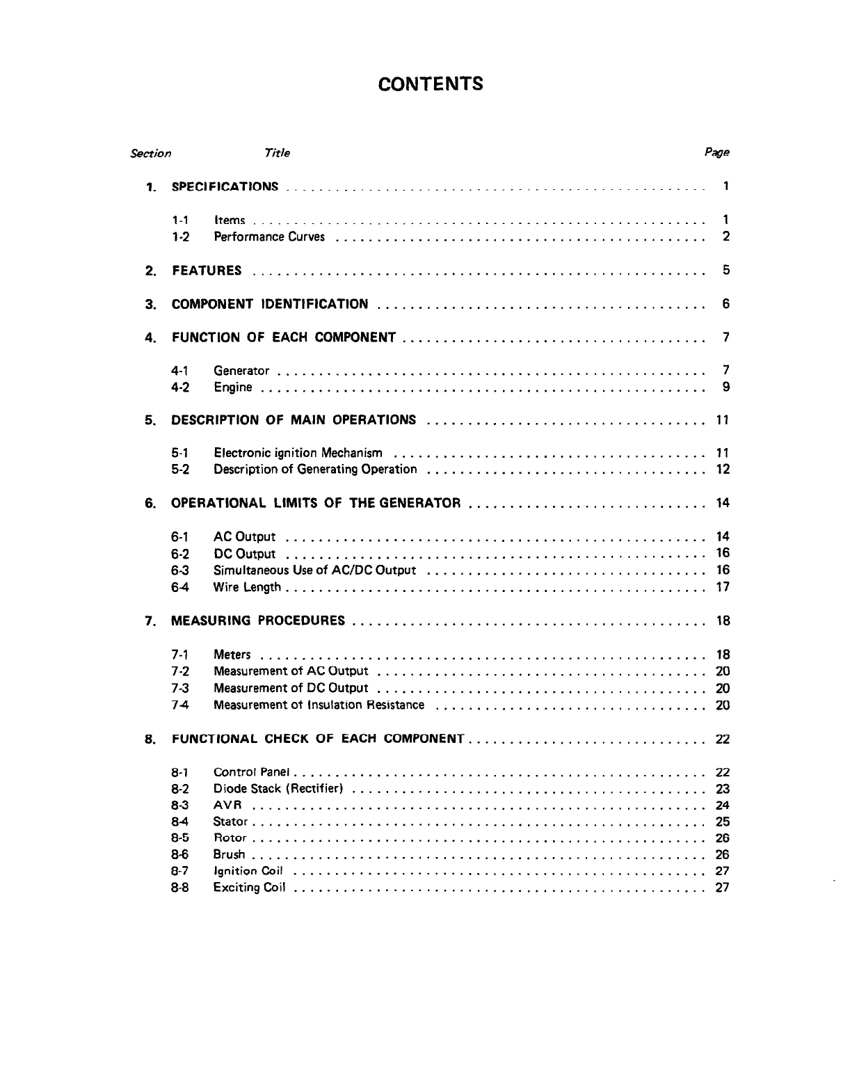
CONTENTS
Section
Title Page
1. SPECIFICATIONS ................................................... 1
1-1 items ....................................................... 1
1-2 Performance Curves ............................................. 2
2.
3.
4.
FEATURES ....................................................... 5
COMPONENT IDENTlFlCATlON ........................................ 6
FUNCTION OF EACH COMPONENT ..................................... 7
4-1 Generator .................................................... 7
4-2 Engine ...................................................... 9
5. DESCRIPTION OF MAIN OPERATIONS .................................. 11
5-1 Electronic ignition Mechanism ...................................... 11
5-2 Description of Generating Operation .................................. 12
6. OPERATIONAL LIMITS OF THE GENERATOR ............................. 14
6-1 AC Output ................................................... 14
6-2 DC Output ................................................... 16
63 Simultaneous Use of AC/DC Output .................................. 16
6-4 Wire Length ................................................... 17
7. MEASURING PROCEDURES ........................................... 18
7-1 Meters ...................................................... 18
7-2 Measurement of AC Output ........................................ 20
7-3 Measurement of DC Output ........................................ 20
7-4 Measurement of Insulation Resistance ................................. 20
8. FUNCTIONAL CHECK OF EACH COMPONENT. ............................ 22
8-1 Control Panel. ................................................. 22
8-2 Diode Stack (Rectifier) ........................................... 23
8-3 AVR ....................................................... 24
8-4 Stator ....................................................... 25
8-5 Rotor ....................................................... 26
8-6 Brush ....................................................... 26
8-7 Ignition Coil .................................................. 27
8-8 Exciting Coil .................................................. 27
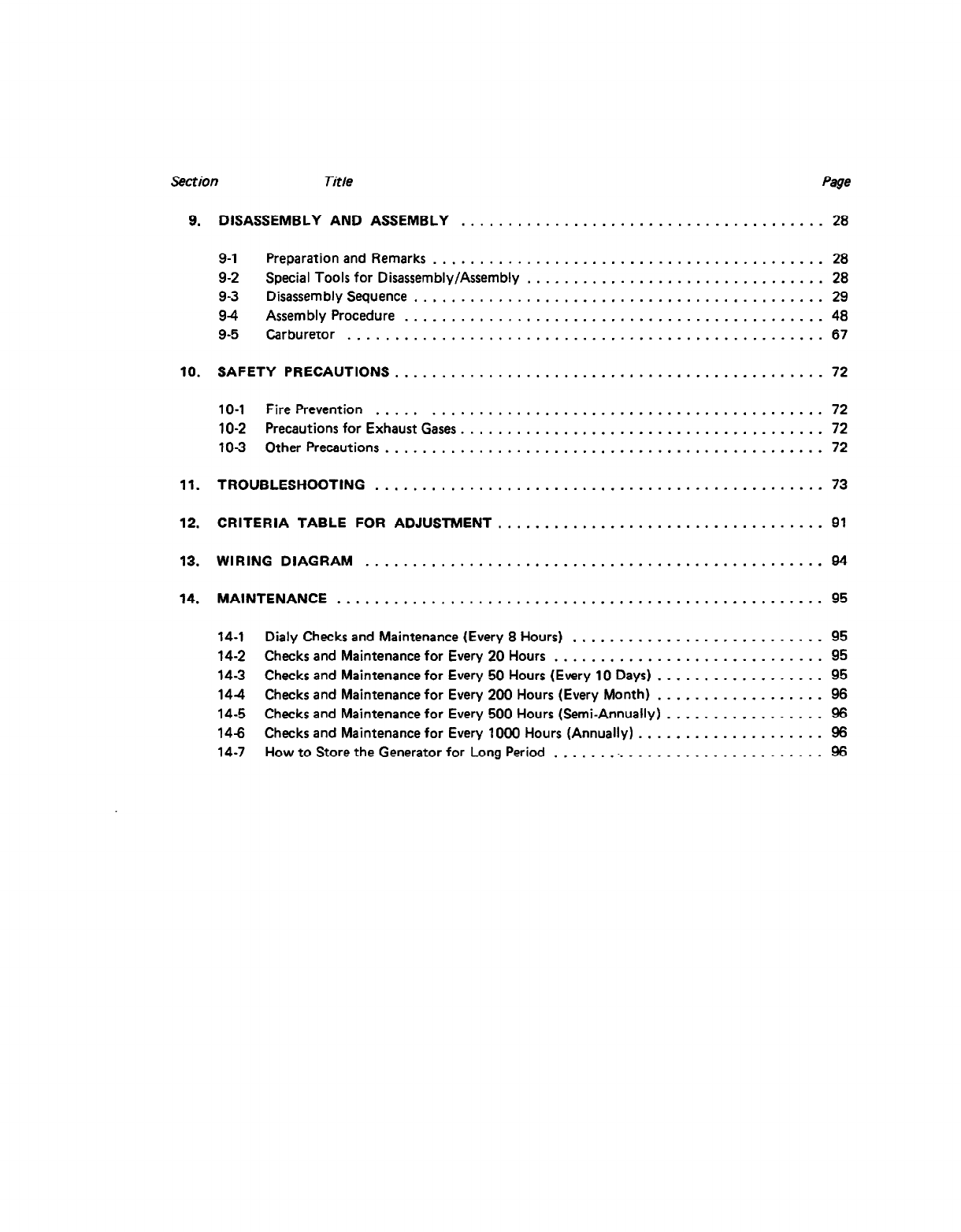
Section Title Page
9.
10.
11.
12.
13.
14.
DISASSEMBLY AND ASSEMBLY ....................................... 28
9-1 Preparation and Remarks .......................................... 28
9-2 Special Tools for Disassembly/Assembly ................................ 28
9-3 Disassembly Sequence ............................................ 29
9-4 Assembly Procedure ............................................. 48
9-5 Carburetor ................................................... 67
SAFETY PRECAUTIONS. ............................................. 72
10-1 Fire Prevention ............................................... 72
10-2 Precautions for Exhaust Gases. ...................................... 72
10-3 Other Precautions ............................................... 72
TROUBLESHOOTING ................................................ 73
CRITERIA TABLE FOR ADJUSTMENT ................................... 91
WIRING DIAGRAM ................................................. 94
MAINTENANCE .................................................... 95
14-1 Daily Checks and Maintenance (Every 8 Hours) ........................... 95
14-2 Checks and Maintenance for Every 20 Hours ............................. 95
14-3 Checks and Maintenance for Every 50 Hours (Every 10 Days) .................. 95
14-4 Checks and Maintenance for Every 200 Hours (Every Month) .................. 96
14-5 Checks and Maintenance for Every 500 Hours (Semi-Annually) ................. 96
14-6 Checks and Maintenance for Every 1000 Hours (Annually) .................... 96
14-7 How to Store the Generator for Long Period .............................. 96
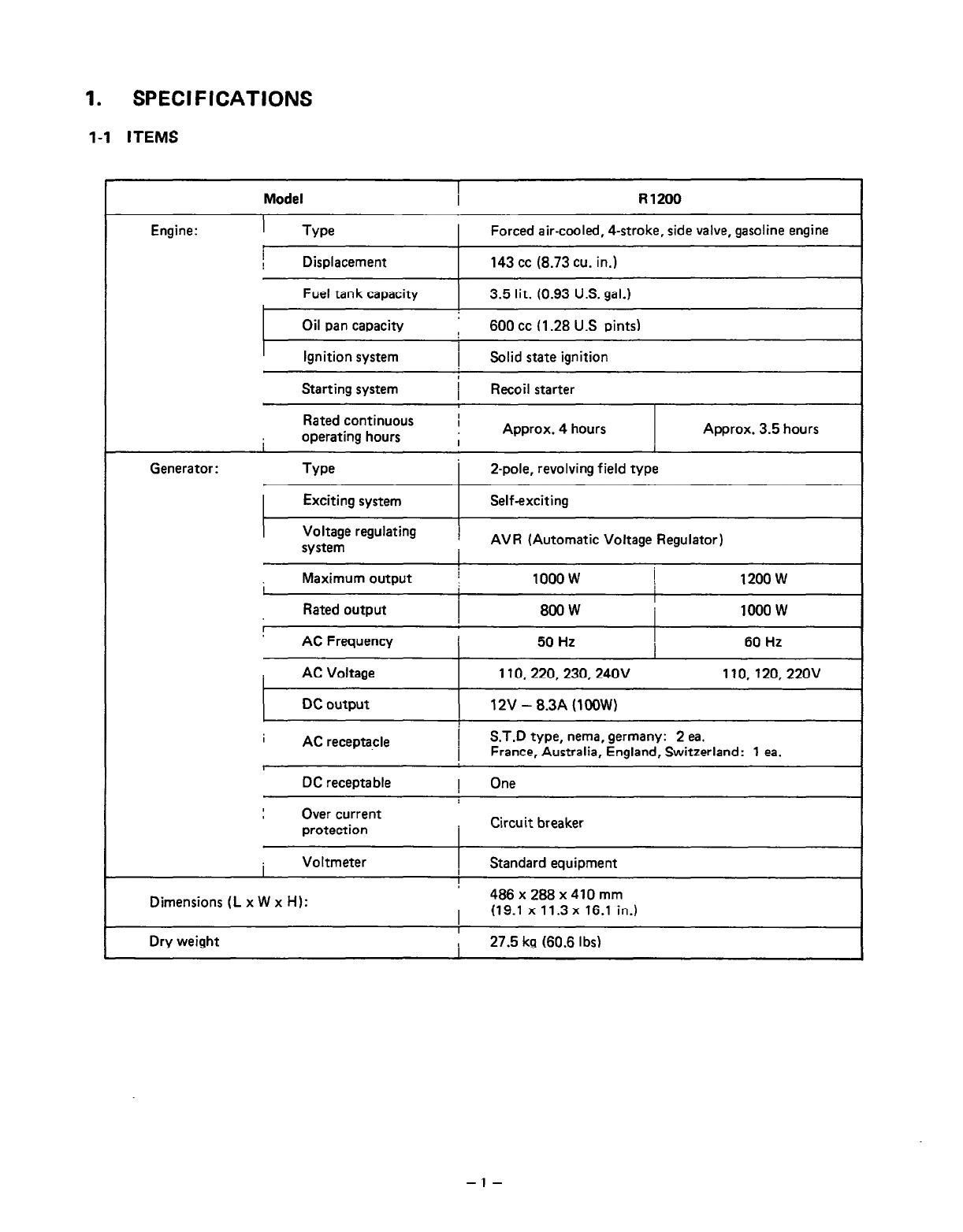
1. SPECIFICATIONS
l-l ITEMS
Model I R1200
Engine: Type I Forced air-cooled, 4-stroke, side valve, gasoline engine
Displacement
Fuel tank capacity
143 cc (8.73 cu. in.)
3.5 lit. (0.93 U.S. gal.)
I
Oil pan capacity , 600 cc (1.28 U.S pints)
I
Ignition system I Solid state ignition
Starting system i Recoil starter I
Rated continuous I
I
operating hours Approx. 4 hours Approx. 3.5 hours
I
I
Generator: Type 2-pole, revolving field type
I Exciting system Self-exciting
I
Voltage regulating I
system AVR (Automatic Voltage Regulator)
I
I Maximum output j 1000 w ! 1200 w
I I
Rated output 800W I 1000 w
AC Frequency
AC Voltage
DC output
50 Hz 1
I 60 Hz
110,220,230,24OV 110,120,220v
12V -8.3A (1OOW)
I
AC receptacle I S.T.D type, nema, germany: 2 ea.
I France, Australia, England, Switzerland: 1 ea.
DC receptable ! One
Over current
protection
I
Circuit breaker
I Voltmeter 1 Standard equipment
Dimensions (L x W x H): 4B6x2BBx410mm
I (19.1 x 11.3 x 16.1 in.)
I
Dry weight
I
I 27.5 kg (60.6 Ibs)
-l-
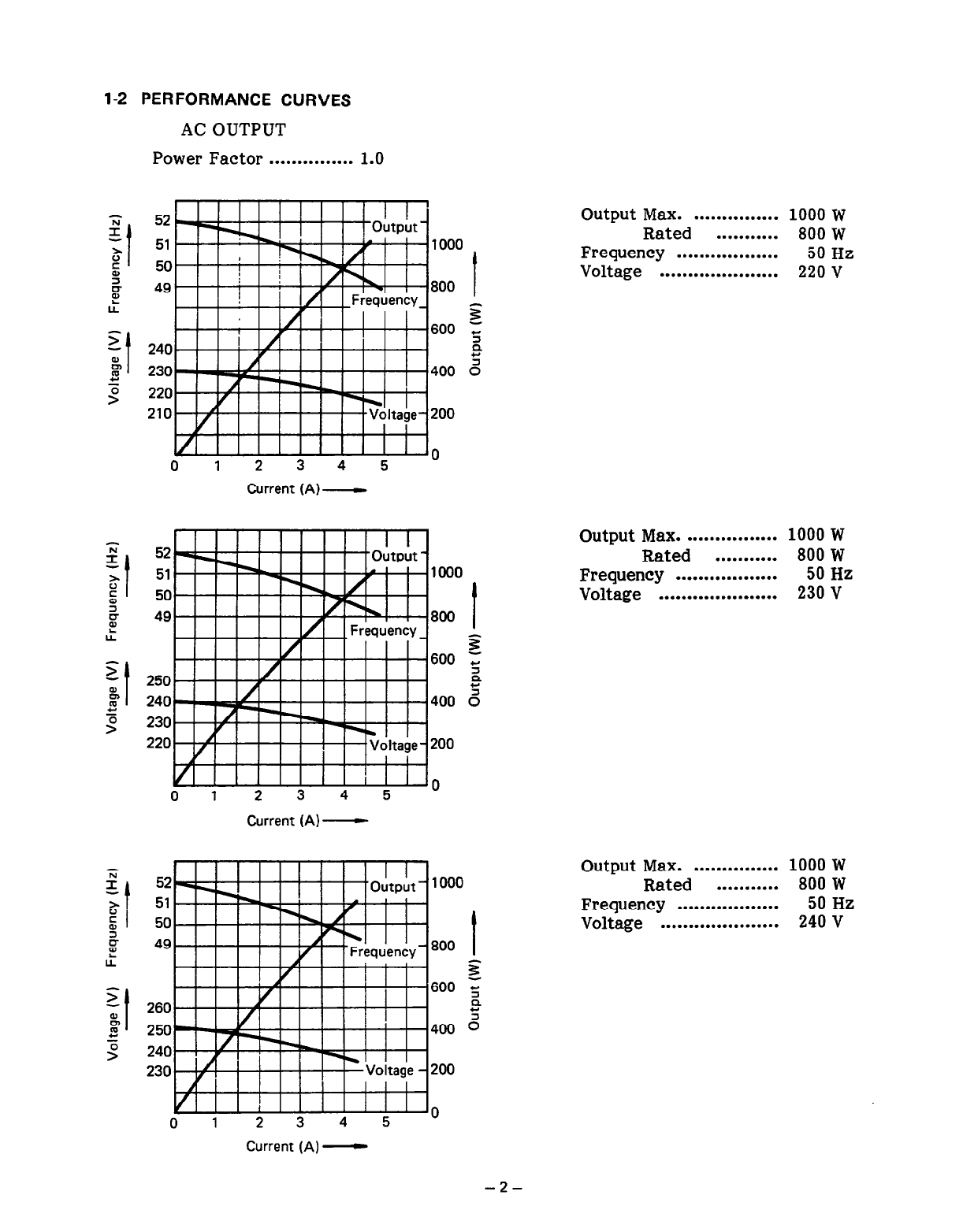
1-2 PERFORMANCE CURVES
AC OUTPUT
Power Factor . . . . . . . . . . . . . . . 1.0
‘;;
I
-I
0’
s
z
E
IA
z
&
2 t
z
>
1 1 1 1 1 1 ’ ’ I
! output i 1000
50
49 800 I
600 z
s
240 P
230 400 2
220
210 200
n
0 1 2 3 4 5 ”
Current (A)-
52
51 1000
50
49 800 I
600 si
w
250 2
240 400 2
230
220 200
I I I I I I I I I I I I
0 1 2 3 4 5 0
Current (A) -
Ti
I -t
52 1000
z 51
;I 50
ii
L 49 800 I
LL s
z
I
600 ‘;
8 260 P
s
8 250 400 0
z
> 240
230 200
0 1 2 3 4 5 0
Current (A) -
Output Max. ............... 1000 w
Rated ........... 800 W
Frequency .................. 50 Hz
Voltage ..................... 220 v
Output Max. ................ 1000 W
Rated ........... 800 W
Frequency .................. 50 Hz
Voltage ..................... 230 V
Output Max. ............... 1000 w
Rated ........... 800 W
Frequency .................. 50 Hz
Voltage ..................... 240 V
-2-
;;;
I
-I
0”
E
?T
L
Ti
I
-t
0”
E
z
e
l.L
z
8
2 t
%
52
51
51 1000
50 50
49
49 800 t
600 s
z z
600 s
B
0.
120--
120 400 3
3
llOr .
110
100 200
0 2 4 6 8 10 0
Current (A)-
62 1000
61
60 800 f
59 z
600 s
Q
5
120 400 0
110
100 200
0 2 4 6 8 10
Current (A)-
62 1000
61
60 800 f
59 600 z
w
240 2
5
230 400 0
220
210 200
01 2 3 4 5 0
Current(A)-
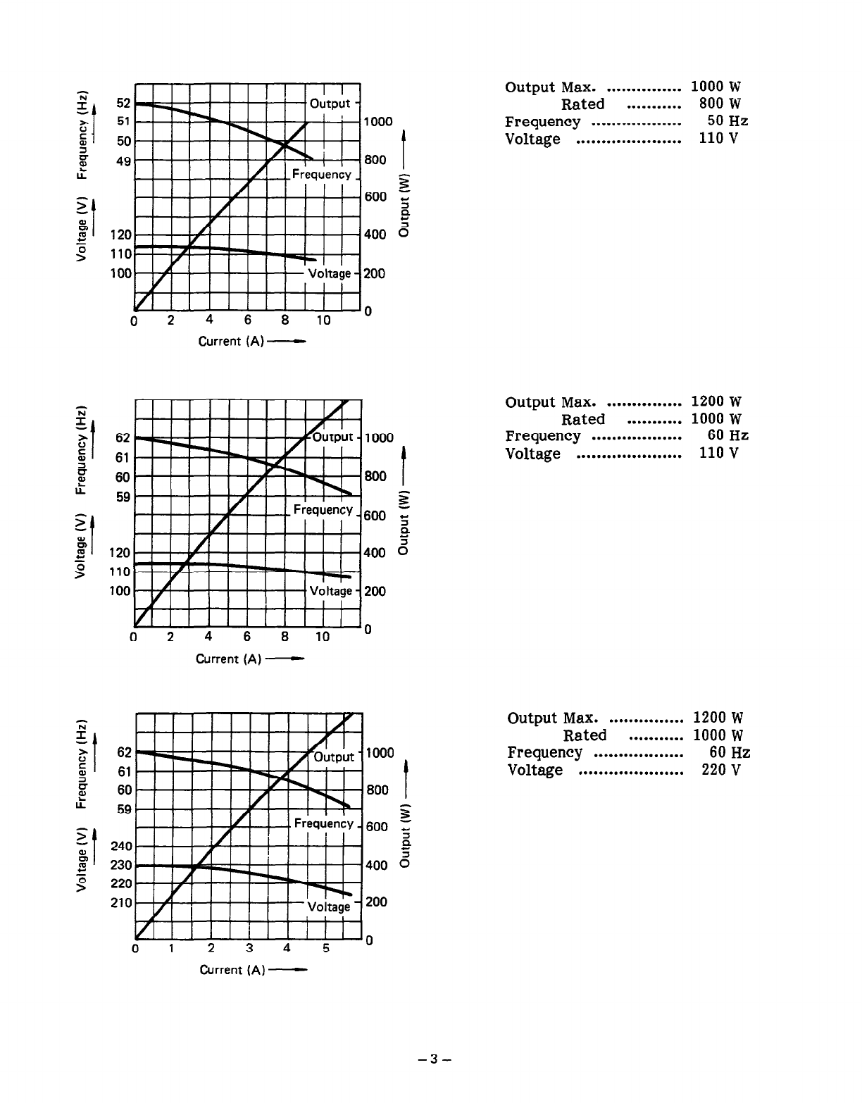
Output Max. ............... 1000 W
Rated ........... 800 W
Frequency .................. 50 Hz
Voltage ..................... 110 v
Output Max. ............... 1200 w
Rated ........... 1000 W
Frequency .................. 60 Hz
Voltage ..................... 110 v
Output Max. ............... 1200 w
Rated ........... 1000 W
Frequency .................. 60 Hz
Voltage ..................... 220 v
-3-
G
I
-1
0”
f
E
lt
z
8
2
I
s
62 1000
61
60 800 t
59 z
600 s
P
s
130 400 0
120
110 200
0 2 4 6 8 10 0
Current (A) -
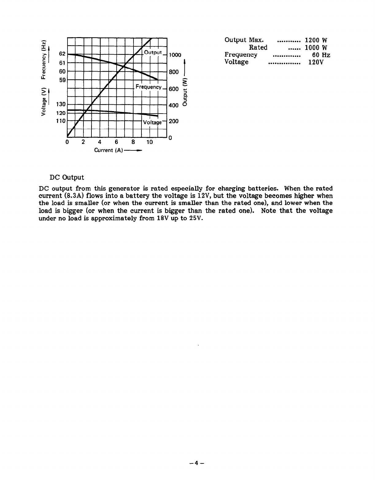
Output Max. ........... 1200 w
Rated ...... 1000 W
Frequency ............. 60 Hz
Voltage ............... 12ov
DC Output
DC output from this generator is rated especially for charging batteries. When the rated
current (8.3A) flows into a battery the voltage is 12V, but the voltage becomes higher when
the load is smaller (or when the current is smaller than the rated one), and lower when the
load is bigger (or when the current is bigger than the rated one). Note that the voltage
under no load is approximately from 18V up to 25V.
-4-
2. FEATURES
(1) Weight of this compact generator with excellent portability is 27.5 kg, which means that
the generator is the lightest one in this class.
(2) This generator with an excellent high performance engine and a large size 3.51i fuel tank
can run continuously for about 4 hours (at the rated load of 50 Hz).
(3) The operating system is concentrated on the front panel, which enables users to easily
handle this generator.
(4) Operations of choking, running, and stopping the engine can easily be executed with a
notch.
(5) As a circuit breaker based on the push button system is employed in this generator,
replacement of a fuse is unnecessary. Troubles which happen in an overload or failure of
devices used can easily be resolved.
(6) Direct current for charging batteries can also be taken out.
(7) Simultaneous use of DC is possible even when AC is used. However, total AC output and
DC output should be within the range of the rated output.
(8) Voltage fluctuation ratio is below 5% because of employment of AVR (Automatic Voltage
Regulator). Accordingly, the stable voltage is always maintained even if the load
fluctuates.
(9) Generally maintenance-free or maintenance is easy because the engine, with a transistor
ignition system, has an excellent startability and no point is employed in this generator.
(10) An ignition plug with a resistor and a plug cap have been employed to prevent electric
wave noises.
-5-
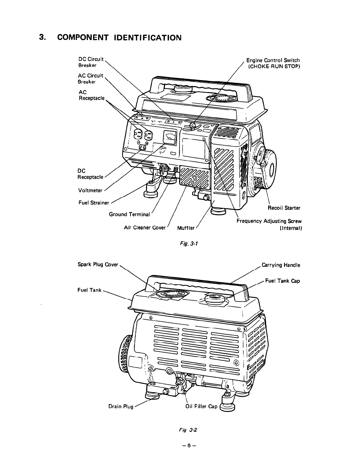
3. COMPONENT IDENTIFICATION
DC Circuit
Breaker \ /
Engine Control Switch
(CHOKE-RUN-STOP)
Ground Terminal
rter
Air Cleaner Cover
/ Muffler /
Recoil Starter
ler /
crew
,,.,.,rnal)
Spark Plug
Fuel Tank
Fig. 3-1
, Carrying Handle
Cover,
Tank Cap
Fig 3-2
-6-
4. FUNCTION OF EACH COMPONENT
4-l GENERATOR
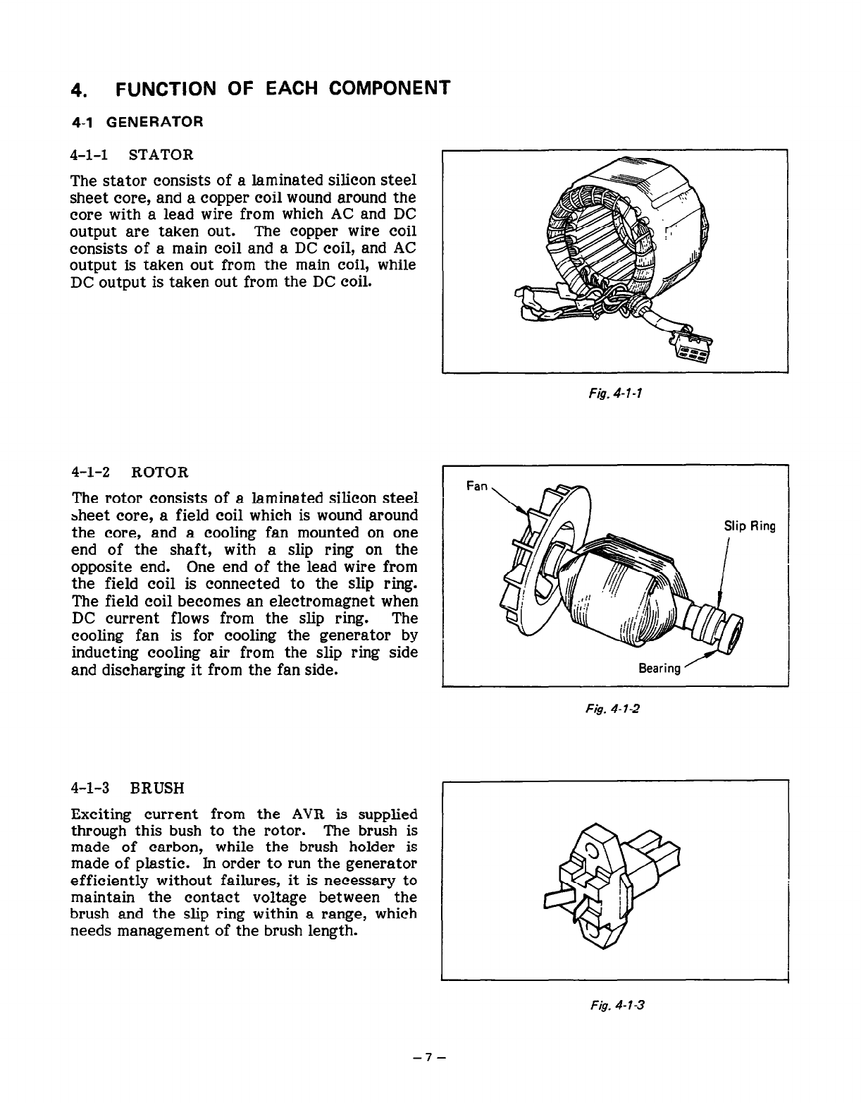
4-l-l STATOR
The stator consists of a laminated silicon steel
sheet core, and a copper coil wound around the
core with a lead wire from which AC and DC
output are taken out. The copper wire coil
consists of a main coil and a DC coil, and AC
output is taken out from the main coil, while
DC output is taken out from the DC coil.
4-l-2 ROTOR
The rotor consists of a laminated silicon steel
sheet core, a field coil which is wound around
the core, and a cooling fan mounted on one
end of the shaft, with a slip ring on the
opposite end. One end of the lead wire from
the field coil is connected to the slip ring.
The field coil becomes an electromagnet when
DC current flows from the slip ring. The
cooling fan is for cooling the generator by
inducting cooling air from the slip ring side
and discharging it from the fan side.
4-l-3 BRUSH
Exciting current from the AVR is supplied
through this bush to the rotor. The brush is
made of carbon, while the brush holder is
made of plastic. In order to run the generator
efficiently without failures, it is necessary to
maintain the contact voltage between the
brush and the slip ring within a range, which
needs management of the brush length.
Fan
F& 4-l-2
Fig. 4-l-3
-7-
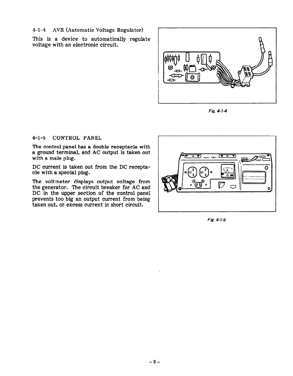
4-l-4 AVR (Automatic Voltage Regulator) I
This is a device to automatically regulate
voltage with an electronic circuit.
4-l-5 CONTROL PANEL
The control panel has a double receptacle with
a ground terminal, and AC output is taken out
with a male plug.
DC current is taken out from the DC recepta-
cle with a special plug.
The voltmeter displays output voltage from
the generator. The circuit breaker for AC and
DC in the upper section of the control panel
prevents too big an output current from being
taken out, or excess current in short circuit.
Fig. 4-14
F& 4-l-5
-8-
4-2 ENGINE
4-2-l CYLINDER AND CRANKCASE
The cylinder and the crankcase of the engine are of a one-piece aluminum die-cast design. The
specific iron cylinder is cast-fitted inside the cylinder. Both the intake and exhaust ports are
positioned at the lateral side of the cylinder. These ports are also cast
by
using a mould with
die-cast cores. The crankcase has its joint face located on the generator side, and it is of an
assembly structure.
4-2-2 MAIN BEARING COVER
The main bearing cover is alminum die-cast and is mounted on the generator side. By removing
it, the interior of the engine can be inspected.
4-2-3 CRANKSHAFT
The crankshaft is constructed of forged carbon steel, and the crankpin is induction-hardened. A
crank gear is pressure-fitted on the generator side of the engine.
4-2-4
CONNECTING ROD AND PISTON
The connecting rod is made of forged aluminum alloy with both the major and minor ends utilized
as bearings. An oil scraper is cast on the major end. The aluminum alloy casting piston has slots
on which two compression rings and one oil ring can be assembled.
4-2-5 CAMSHAFT
The camshaft is made of special cast iron and has intake and exhaust valve drive cams, each of
which engages with the camgear. An exclusive aluminum alloy is used on each end of the
camshaft in the place of bearings. (Ball bearings are not used.)
4-Z-6 VALVE ARRANGEMENT
The intake valve is arranged in the generator side, while the exhaust valve is arranged in the
recoil side.
4-2-7 CYLINDER HEAD
The cylinder head is die-cast aluminum and has a Ricardo type combustion chamber featuring
greater volume capacity for improved combustion efficiency. For easier ignition plug mainte-
nance the cylinder head is positioned vertically.
4-2-8 GOVERNOR
The centrifugal weight governor ensures constant engine speed, regardless of load fluctuations
(the governor is mechanically linked to the governor drive gear).
4-2-9 COOLING SYSTEM
The cooling system with a cooling fan, which also functions as a flywheel, compulsorily sends
cooling air to the cylinder and the cylinder head and cools them. This forced air cooling system
has a baffle plate and a head cover.
4-Z-10
LUBRICATION SYSTEM
The moving and sliding parts inside the engine are lubricated with
the
oil scraper fitted on the
connecting rod by scraping and splashing oil in the crankcase.
-9-
4-2-l 1 IGNITION SYSTEM
The ignition system is based on a flywheel/magneto system and its ignition timing is set at 230C
before top dead center. The magneto consists of a flywheel and an ignition coil. The flywheel
(functioning also as a fan) is mounted on the crankshaft, while the ignition coil is mounted on the
crankcase.
4-2-12 CARBURETOR
The horizontal suction type carburetor employed here can provide excellent starting, good
acceleration, low fuel consumption, and superior output. The carburetor setting is matched to
the generator set. (On details concerning the carburetor construction and others, see the
paragraph dealing with carburetor construction and disassembly/assembly.)
4-2-13 AIR CLEANER
The air cleaner is a semi-wet type and contains a sponge element.
-10-
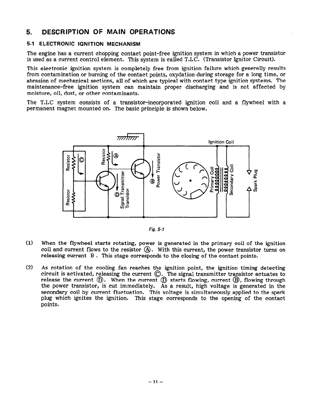
5. DESCRIPTION OF MAIN OPERATIONS
5-l ELECTRONIC IGNITION MECHANISM
The engine has a current chopping contact point-free ignition system in which a power transistor
is used as a current control element. This system is called T.I.C. (Transistor Ignitor Circuit).
This electronic ignition system is completely free from ignition failure which generally results
from contamination or burning of the contact points, oxydation during storage for a long time, or
abrasion of mechanical sections, all of which are typical with contact type ignition systems. The
maintenance-free ignition system can maintain proper discharging and is not affected by
moisture, oil, dust, or other contaminants.
The T.1.C system consists of a transistor-incorporated ignition coil and a flywheel with a
permanent magnet mounted on. The basic principle is shown below.
I
Ignition Coil
I E @ r
*go .$
$1 r ‘1 Q b
z
.-
E P =
LT
\s>l
f Ll f ‘CC = 8
r 8 I
z
.-
E
? ~~~
@5 ,” l ?“f $
5
2
;
o$j 5 I% ki f%
rn
&F
iTI-
F&. 5-7
(1) When the flywheel starts rotating, power is generated in the primary coil of the ignition
coil and current flows to the resistor @. With this current? the power transistor turns on
releasing current B . This stage corresponds to the closing of the contact points.
(2) As rotation of the cooling fan reaches the ignition point, the ignition timing detecting
circuit is activated, releasing the current 0. The signal transmitter transistor actuates to
release the current @. When the current @ starts flowing, current @, flowing through
the power transistor, is cut immediately. As a result, high voltage is generated in the
secondary coil by current fluctuation. This voltage is simultaneously applied to the spark
plug which ignites the ignition. This stage corresponds to the opening of the contact
points.
-11-
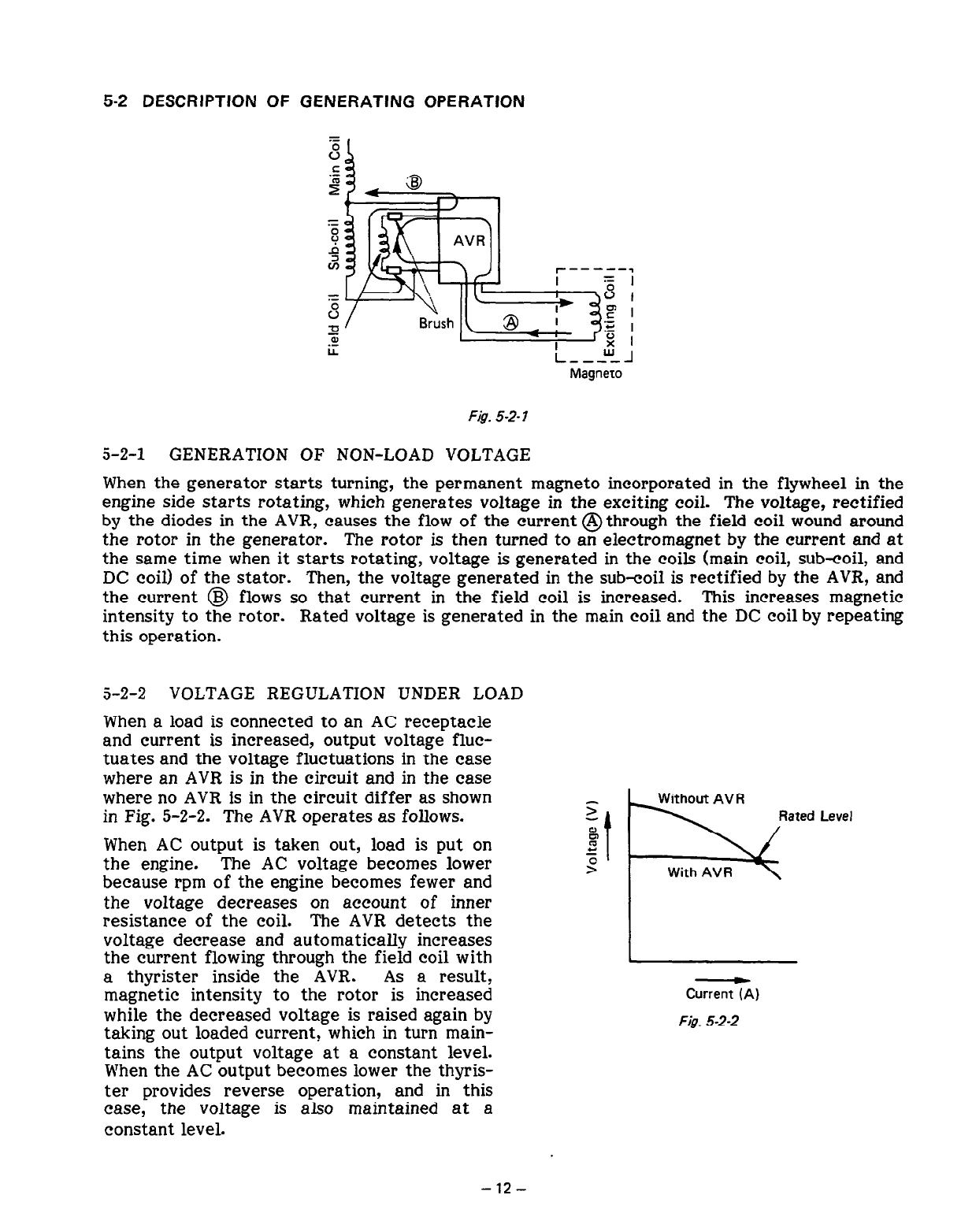
5-2 DESCRIPTION OF GENERATING OPERATION
I------- = ,
8 I
P I
‘3
‘6
x I
L ---w_J
Magneto
F@. 5-2- I
5-2-l GENERATION OF NON-LOAD VOLTAGE
When the generator starts turning, the permanent magneto incorporated in the flywheel in the
engine side starts rotating, which generates voltage in the exciting coil. The voltage, rectified
by the diodes in the AVR, causes the flow of the current @through the field coil wound around
the rotor in the generator. The rotor is then turned to an electromagnet by the current and at
the same time when it starts rotating, voltage is generated in the coils (main coil, sub-coil, and
DC coil) of the stator. -Then, the voltage generated in the sub-coil is rectified by the AVR, and
the current @ flows so that current in the field coil is increased. This increases magnetic
intensity to the rotor. Rated voltage is generated in the main coil and the DC coil by repeating
this operation.
5-2-2 VOLTAGE REGULATION UNDER LOAD
When a load is connected to an AC receptacle
and current is increased, output voltage fluc-
tuates and the voltage fluctuations in the case
where an AVR is in the circuit and in the case
where no AVR is in the circuit differ as shown
in Fig. 5-2-2. The AVR operates
as
follows.
When AC output is taken out, load is put on
the engine. The AC voltage becomes lower
because rpm of the engine becomes fewer and
the voltage decreases on account of inner
resistance of the coil. The AVR detects the
voltage decrease and automatically increases
the current flowing through the field coil with
a thyrister inside the AVR. As a result,
magnetic intensity to the rotor is increased
while the decreased voltage is raised again by
taking out loaded current, which in turn main-
tains the output voltage at a constant level.
When the AC output becomes lower the thyris-
ter provides reverse operation, and in this
case,
the voltage is also maintained at a
constant level.
Rated Level
Current (A)
F& 5-2-2
-12-
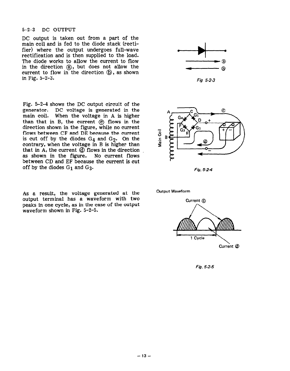
j-2-3 DC OUTPUT
DC output is taken out from a part of the
main coil and is fed to the diode stack (recti-
fier) where the output undergoes full-wave
rectification and is then supplied to the load.
The diode works to allow the current to flow
in the direction @, but does not allow the
current to flow in the direction @I, as shown
in Fig. 5-2-3. Fig 5-23
Fig. 5-2-4 shows the DC output circuit of the
generator. DC voltage is generated in the
main coil. When the voltage in A is higher
than that in B, the current @ flows in the
direction shown in the figure, while no current
flows between CF and DE because the current
is cut off by the diodes G4 and G2. On the
contrary, when the voltage in B is higher than
that in A, the current @I flows in the direction
as shown in the figure. No current flows
between CD and EF because the current is cut
off by the diodes G1 and G3.
=
8
Fis. 5-24
As a result, the voltage generated at the
output terminal has a waveform with two
peaks in one cycle, as in the case of the output
waveform shown in Fig. 5-2-5.
Output Waveform
Current @
Curr&t @
F&. 5-2-5
- 13 -
6. OPERATIONAL LIMITS OF THE GENERATOR
6-1 AC OUTPUT
Electric appliances normally have rating levels showing the rated voltage, frequency, power
consumption (input power), and other things. The power consumption specified on such a label is
required to drive the appliance. However, when an appliance is connected to the generator, the
power factor and starting current should also be taken into account.
6-l-l NET RESISTANCE LOAD
Incandescent lamps, electric heaters etc. can be run on the generator having a capacity
equivalent to the total of the respective appliances. Each of these appliances normally has a
power factor of 1.0.
Example: The generator having a rated voltage output of 1000 W can provide enough power to
operate up to ten 100 W lamps.
6-l-2 ELECTRIC APPLIANCES WITH A POWER FACTOR OF LESS THAN 1.0
Fluorescent lamps and mercury lamps normally have a low power factor, and accordingly, the
generator is required to generate approximately 1.2 to 2 times the power consumed by each
loaded appliance.
Example: With the generator having a rated voltage output of 1000 W, six to ten 80 W mercury
lamps can be operated.
6-l-3 MOTOR LOAD
Generally, motors require a large starting current every time they are started or begin rotating.
The motor starting load supplied from the generator becomes the largest when starting a normal
operation mode. The rates of power supply, which the generator is required to produce for motor
loads, are categorized into two cases, depending on the types of the motor used and load
condition at the time of starting.
(1) Motors (mainly rectifier motors) used for electric drills and similar devices:
Normally, the motors used for electric drills and similar appliances require the generator to
produce approximately 1.2 to 3 times the power consumed at the time of starting.
Example: To drive a 300 W electric drill, a generator with a maximum output of about 400 W to
900 W or more is necessary.
(2) Motors (mainly induction motors) used for pumps and compressors:
As pumps and compressors have loads even when they are started, the generator is required to
produce 3 to 5 times the power consumed during normal running.
Example: To drive a 200 W submersible pump, a generator with a maximum output of 600 W to
1000 W or more is necessary.
6-l-4 IN THE CASE WHERE POWER CONSUMPTION IS NOT DISPLAYED ON
THE RATING PANEL
Sometimes, the rating panel of an electric appliance does not carry its power consumption, but
only shows the mechanical equivalent to the power consumption. In this case, it is necessary to
-14
-
calculate the power consumption of the device involved. The calculated power consumption is
adjusted depending on the type of the load, and according to paragraphs from (1) to (3).
(Power consumption) = (Mechanical equivalent of a device) + (Efficiency)
Efficiency
Motors: 0.6 2. 0.8
Fluorescent lamps: 0.7 x0.8
Example: As for a 40 W fluorescent lamp with a lighting output of 40 W, and assuming that the
power consumption of this lamp is 0.7, the power consumption can be calculated as
follows:
40 + 0.7 = 57 W
Furthermore, as per paragraph (2), the power consumption is multiplied by a factor of
1.2 to 2, producing a power consumption of 70 to 115 W. Therefore, with a generator
having a rated output of 1000 W, 8 to 14 lamps can be used.
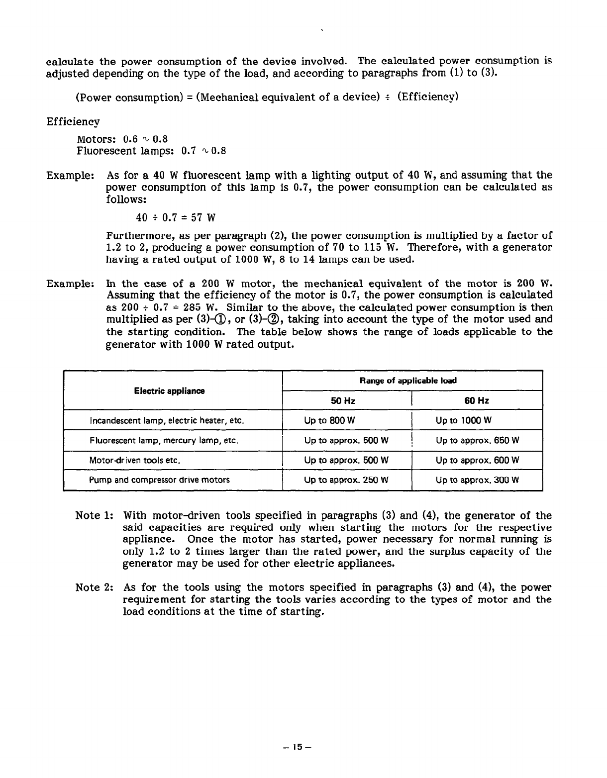
Example: In the case of a 200 W motor, the mechanical equivalent of the motor is 200 W.
Assuming that the efficiency of the motor is 0.7, the power consumption is calculated
as 200 I 0.7 = 285 W. Similar to the above, the calculated power consumption is then
multiplied as per (3)a, or (3)-a, taking into account the type of the motor used and
the starting condition. The table below shows the range of loads applicable to the
generator with 1000 W rated output.
Electric appliance Range of applicable load
50 Hz 60 Hz
I
Incandescent lamp, electric heater, etc. I Up to 800 W I Upto 1ooow I
Fluorescent lamp, mercury lamp, etc. Up to approx. 500 W
Motordriven tools etc. Up to approx. 500 W
Pump and compressor drive motors Up to approx. 250 W
Up to approx. 650 W
Up to approx. 600 W
Up to approx. 300 W
Note 1: With motor-driven tools specified in paragraphs (3) and (4), the generator of the
said capacities are required only when starting the motors for the respective
appliance. Once the motor has started, power necessary for normal running is
only 1.2 to 2 times larger than the rated power, and the surplus capacity of the
generator may be used for other electric appliances.
Note 2: As for the tools using the motors specified in paragraphs (3) and (4), the power
requirement for starting the tools varies according to the types of motor and the
load conditions at the time of starting.
-15-
6-2 DC OUTitJT
When the generator is employed to recharge batteries, attentions should be paid to the specific
gravity of electrolyte in each battery.
6-2-l MEASUREMENT OF ELECTROLYTE’S SPECIFIC GRAVITY
The specific gravity of an electrolyte varies according to temperature; so it is converted to one
in case of 200C.
s20 = St + 0.0007 (t - 20)
where
S20: The specific gravity at 200C
St : Measured value
t : Temperature at the time of measurement (Electrolyte)
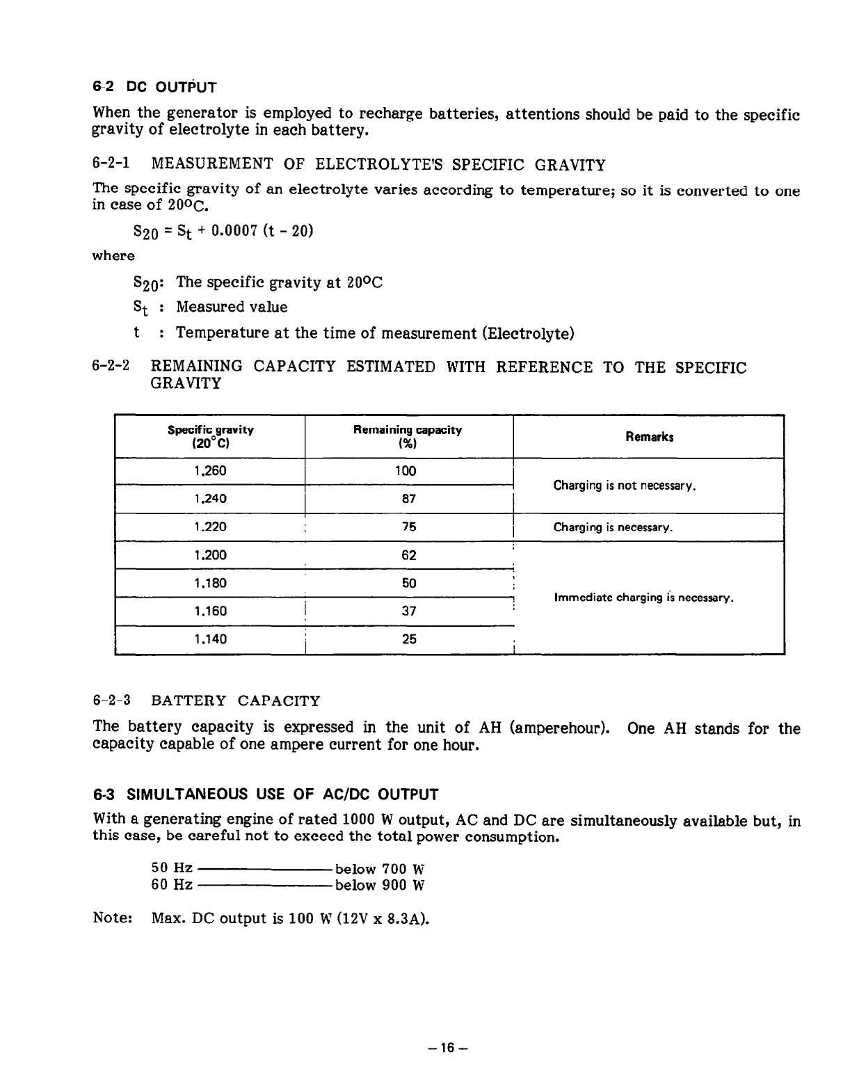
6-2-2 REMAINING CAPACITY ESTIMATED WITH REFERENCE TO THE SPECIFIC
GRAVITY
Specific gravity
(20°C) Remaining capacity
(%I
I .260 100
I .240 87
1.220 75
Remarks
Charging is not necessary.
Charging is necessary.
I
I .200 62
1.180
1.160
I .I40
I
50
37
25
Immediate charging is necessary.
I
6-2-3 BATTERY CAPACITY
The battery capacity is expressed in the unit of AH (amperehour). One AH stands for the
capacity capable of one ampere current for one hour.
6-3 SIMULTANEOUS USE OF AC/DC OUTPUT
With a generating engine of rated 1000 W output, AC and DC are simultaneously available but, in
this case, be careful not to exceed the total power consumption.
50 Hz below 700 W
60 Hz below 900 W
Note: Max. DC output is 100 W (12V x 8.3A).
-16-
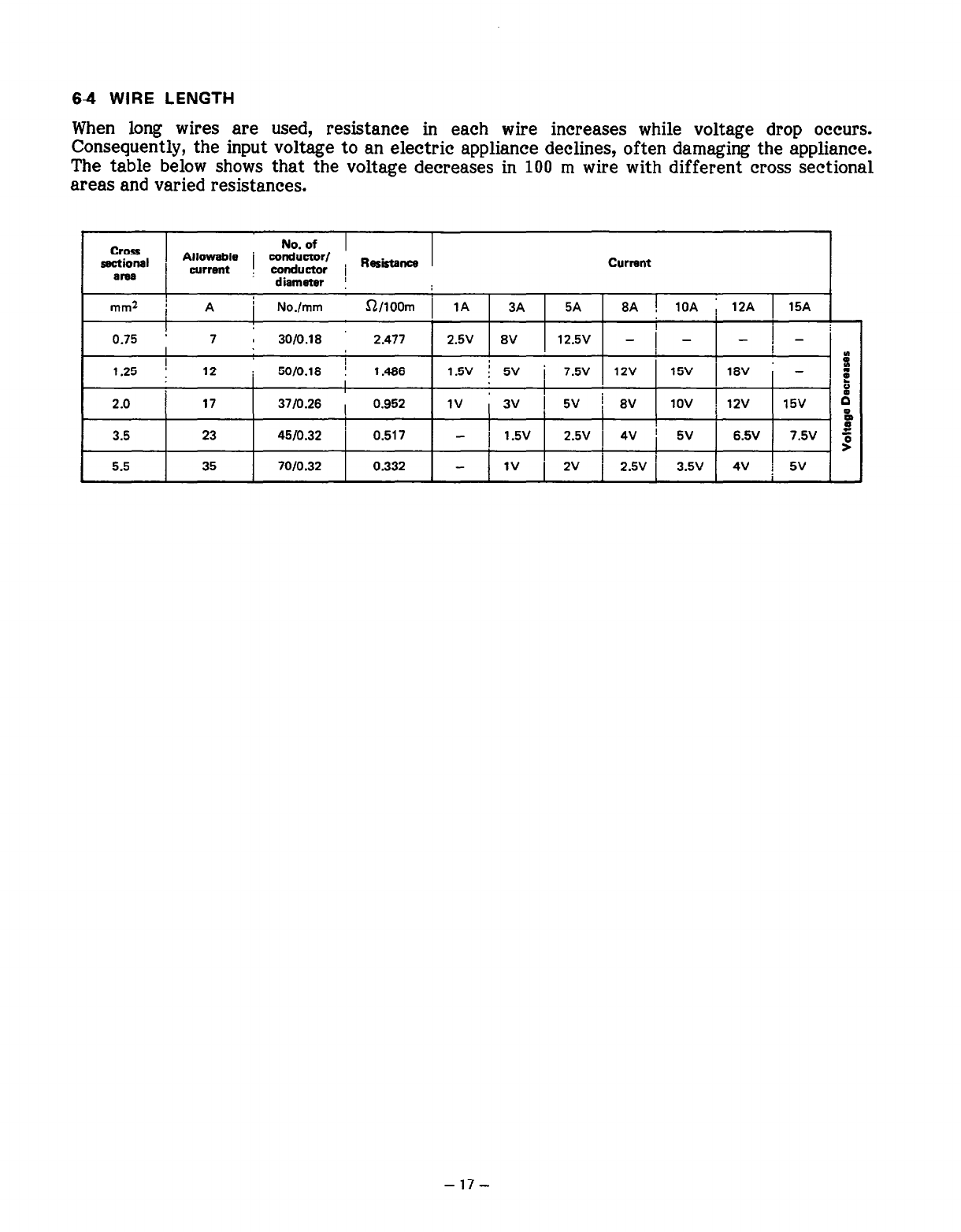
64 WIRE LENGTH
When long wires are used, resistance in each wire increases while voltage drop occurs.
Consequently, the input voltage to an electric appliance declines, often damaging the appliance.
The table below shows that the voltage decreases in 100 m wire with different cross sectional
areas and varied resistances.
Cross
sectional
araa
No. of 1
Alloweble j
COIldUCtO~/
current conductor i Rasistanca
diameter !
Current
I
mm2 j A j No./mm a/lOOm 1 1A 3A 5A 8A ! 10A i 12A 1 15A
I ’
0.75 * 7 : 3010.18 2.477 2.5V 8V 12.5V _
I -/- ] - j
.
I
1.25 : 12 : 5010.18 ! 1.466 1.w ! 5v i 7.5V 12v 15v 18V -
i 17
I I
I b
2.0 37/0.26 , 0.952 1v ,3v 1 5V ! 8V 1ov i 12v 15v d
0
z
3.5 23 4510.32 ’ 0.517 ’
- j 1.5V 2.5V 1 4V ’ 5V 6% 7.5v 5
>
5.5 35 7010.32 0.332 - 3.5v 4v
-17-
7. MEASURING PROCEDURES
7-1 METERS
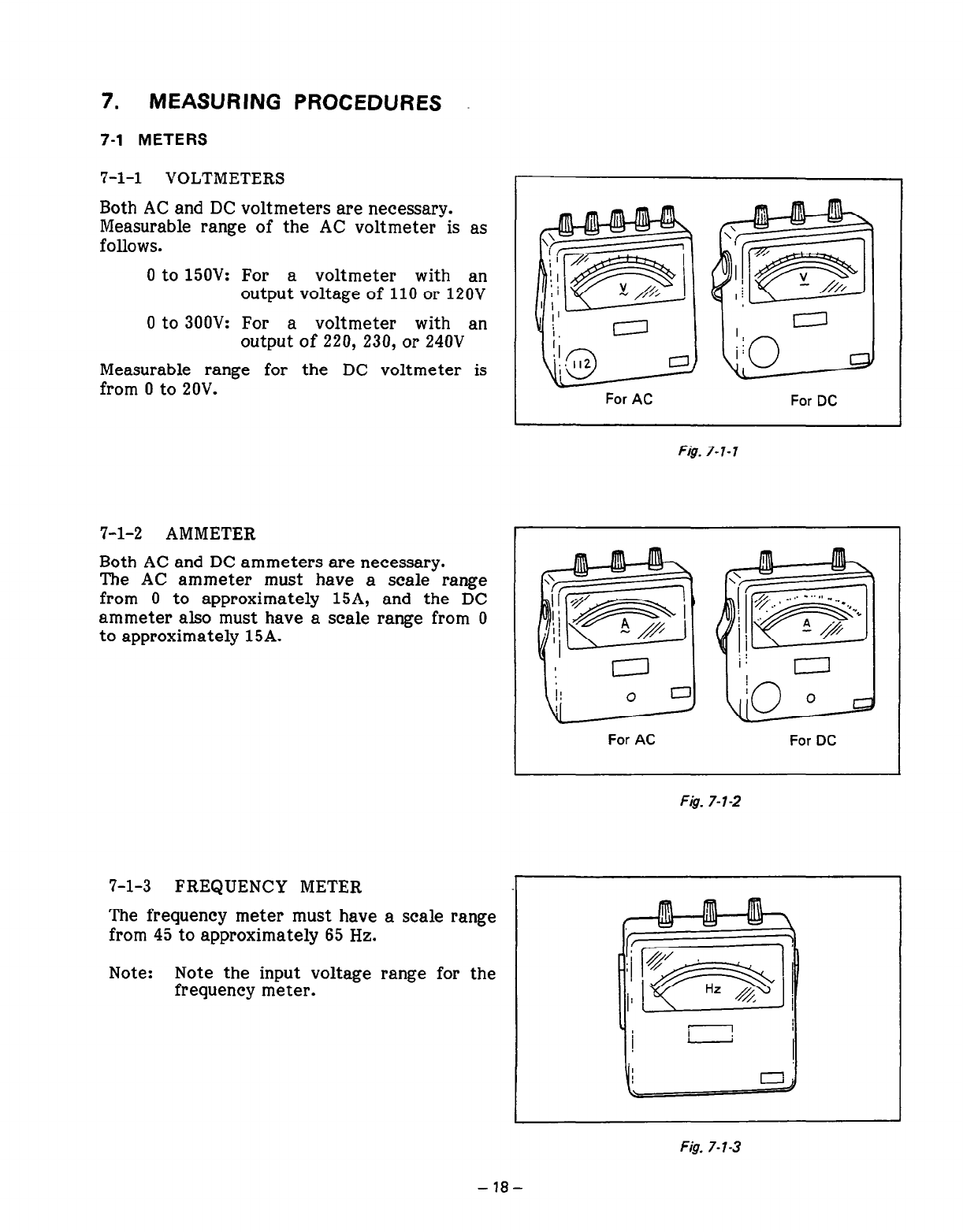
7-l-l VOLTMETERS
Both AC and DC voltmeters are necessary.
Measurable range of the AC voltmeter is as
follows.
0 to 15OV: For a voltmeter with an
output voltage of 110 or 120V
0 to 300V: For a voltmeter with an
output of 220, 230, or 240V
Measurable range for the DC voltmeter is
from 0 to 20V.
7-l-2 AMMETER
Both AC and DC ammeters are necessary.
The AC ammeter must have a scale range
from 0 to approximately 15A, and the DC
ammeter also must have a scale range from 0
to approximately 15A.
7-l-3 FREQUENCY METER
The frequency meter must have a scale range
from 45 to approximately 65 Hz.
Note: Note the input voltage range for the
frequency meter.
For AC For DC
Fig. 7-l- 1
For AC For DC
FI& 7-l-2
II ’
m
;i ,71;
.: [m j
I- 1
Fig. 7- l-3
-18-
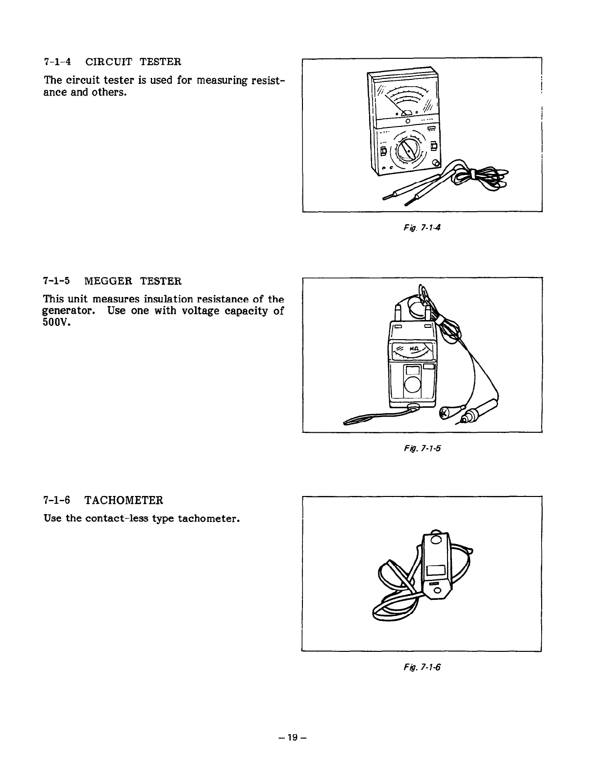
7-l-4 CIRCUIT TESTER
The circuit tester is used for measuring resist-
ance and others.
I
Fig. 7-l-4
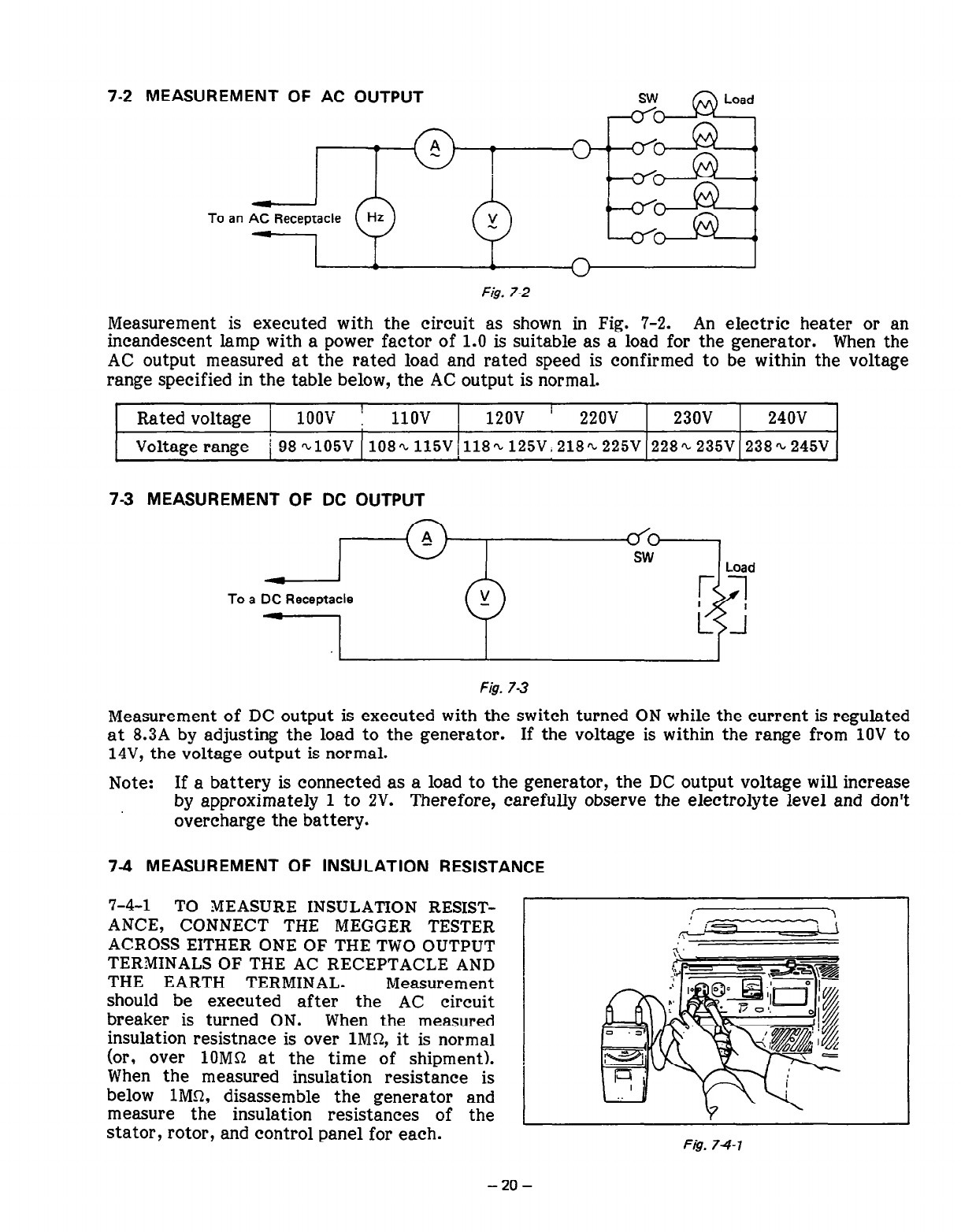
7-l-5 MEGGER TESTER
This unit measures insulation resistance of the
generator. Use one with voltage capacity of
5oov.
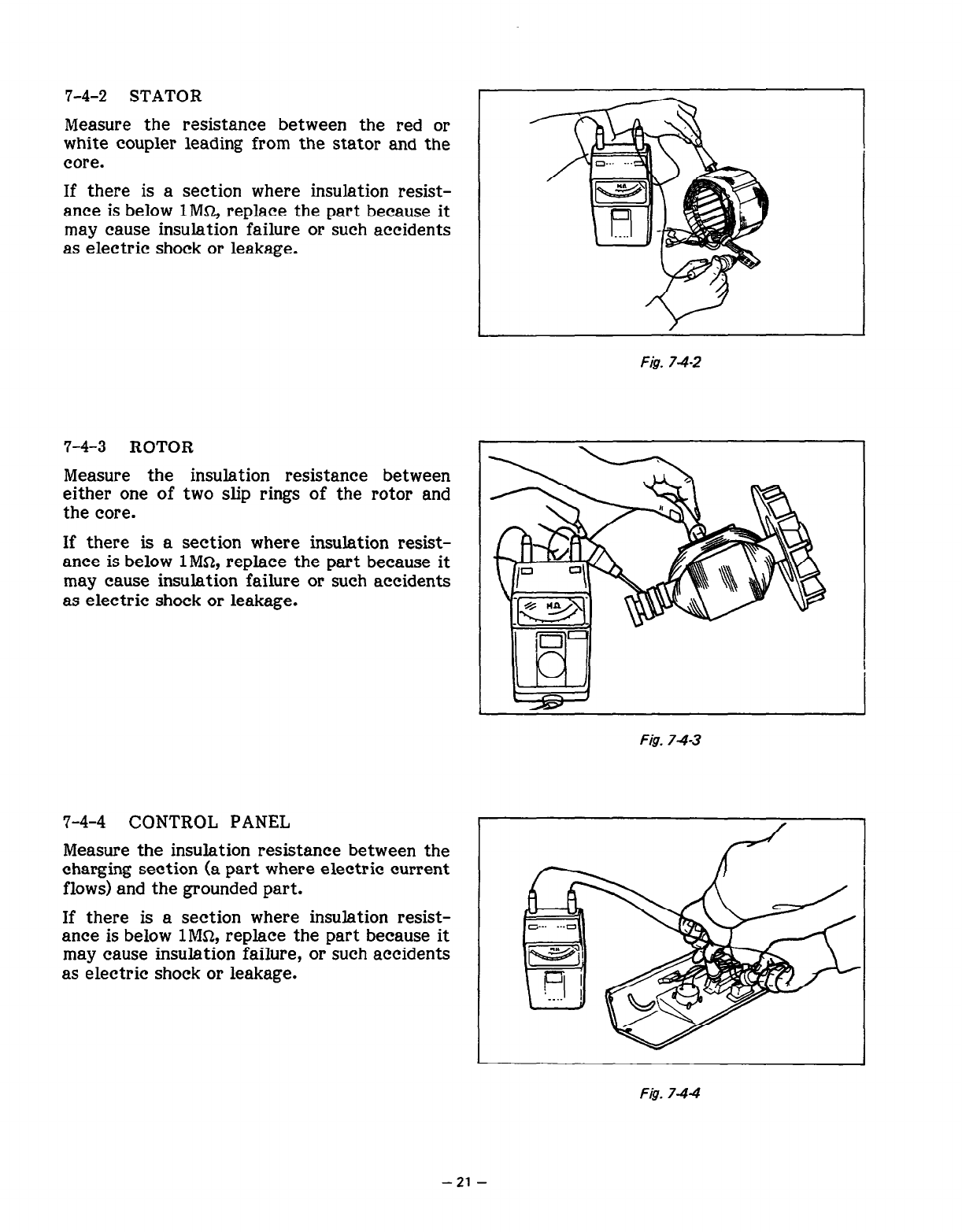
7-l-6 TACHOMETER
Use the contact-less type tachometer.
Fig. 7-l-5
I 1
Fig. 7-l-6
-19-
7-2 MEASUREMENT OF AC OUTPUT
+ii+~~
To an AC Receptacle
Fig. 7-2
Measurement is executed with the circuit as shown in Fig. 7-2. An electric heater or an
incandescent lamp with a power factor of 1.0 is suitable as a load for the generator. When the
AC output measured at the rated load and rated speed is confirmed to be within the voltage
range specified in the table below, the AC output is normal.
I 1
Rated voltage 1 1OOV 1 1lOV 120v I 220v 230V 240V
Voltage range i 98~105V 108~115V~118~125V~218~~225V 228~235V 238~245V
73 MEASUREMENT OF DC OUTPUT
To a DC Receptacle
Fig. 73
Measurement of DC output is executed with the switch turned ON while the current is regulated
at 8.3A by adjusting the load to the generator. If the voltage is within the range from 1OV to
14V, the voltage output is normal.
Note: If a battery is connected as a load to the generator, the DC output voltage will increase
by approximately 1 to 2V. Therefore, carefully observe the electrolyte level and don’t
overcharge the battery.
7-4 MEASUREMENT OF INSULATION RESISTANCE
7-4-l TO MEASURE INSULATION RESIST-
ANCE, CONNECT THE MEGGER TESTER
ACROSS EITHER ONE OF THE TWO OUTPUT
TERMINALS OF THE AC RECEPTACLE AND
THE EARTH TERMINAL. Measurement
should be executed after the AC circuit
breaker is turned ON. When the measured
insulation resistnace is over lMQ, it is normal
(or, over 1OMQ at the time of shipment).
When the measured insulation resistance is
below lMn, disassemble the generator and
measure the insulation resistances of the
stator, rotor, and control panel for each. F&. 74-1
-20-
7-4-2 STATOR
Measure the resistance between the red or
white coupler leading from the stator and the
core.
If there is a section where insulation resist-
ance is below 1MQ replace the part because it
may cause insulation failure or such accidents
as electric shock or leakage.
7-4-3 ROTOR
Measure the insulation resistance between
either one of two slip rings of the rotor and
the core.
If there is a section where insulation resist-
ance is below lMS2, replace the part because it
may cause insulation failure or such accidents
as electric shock or leakage.
7-4-4 CONTROL PANEL
Measure the insulation resistance between the
charging section (a part where electric current
flows) and the grounded part.
If there is a section where insulation resist-
ance is below lMS2, replace the part because it
may cause insulation failure, or such accidents
as electric shock or leakage.
I
Fig. 74-2
Fig. 74-3
Fig. 744
-21-
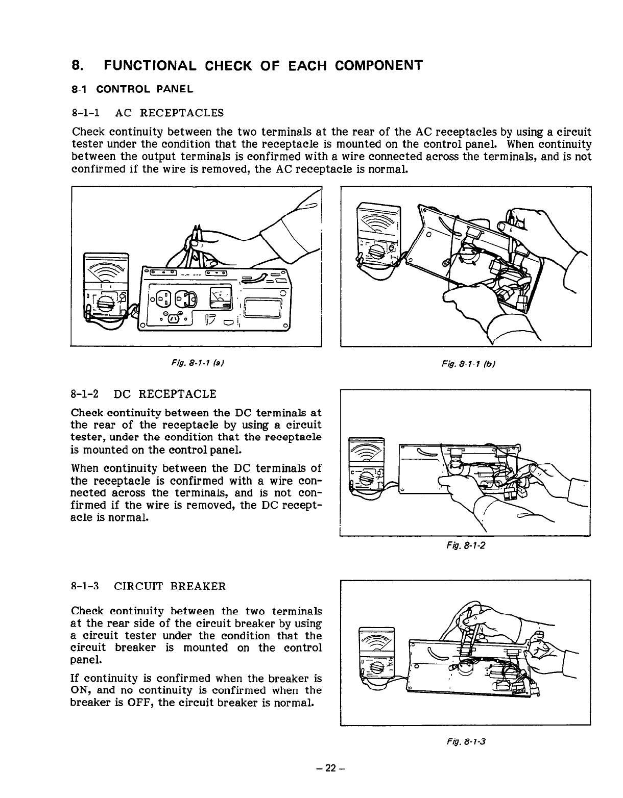
Fig. 8-l-l (a)
8-l-2 DC RECEPTACLE
Check continuity between the DC terminals at
the rear of the receptacle by using a circuit
tester, under the condition that the receptacle
is mounted on the control panel.
When continuity between the DC terminals of
the receptacle is confirmed with a wire con-
nected across the terminals, and is not con-
firmed if the wire is removed, the DC recept-
acle is normal.
8-l-3 CIRCUIT BREAKER
Check continuity between the two terminals
at the rear side of the circuit breaker by using
a circuit tester under the condition that the
circuit breaker is mounted on the control
panel.
If continuity is confirmed when the breaker is
ON, and no continuity is confirmed when the
breaker is OFF, the circuit breaker is normal.
Fig. 8- I- 1 (b)
8.
FUNCTIONAL CHECK OF EACH COMPONENT
8-1 CONTROL PANEL
8-l-l AC RECEPTACLES
Check continuity between the two terminals at the rear of the AC receptacles by using a circuit
tester under the condition that the receptacle is mounted on the control panel. When continuity
between the output terminals is confirmed with a wire connected across the terminals, and is not
confirmed if the wire is removed, the AC receptacle is normal.
Fig. 8-l-2
F&J. 8-7-3
-22-
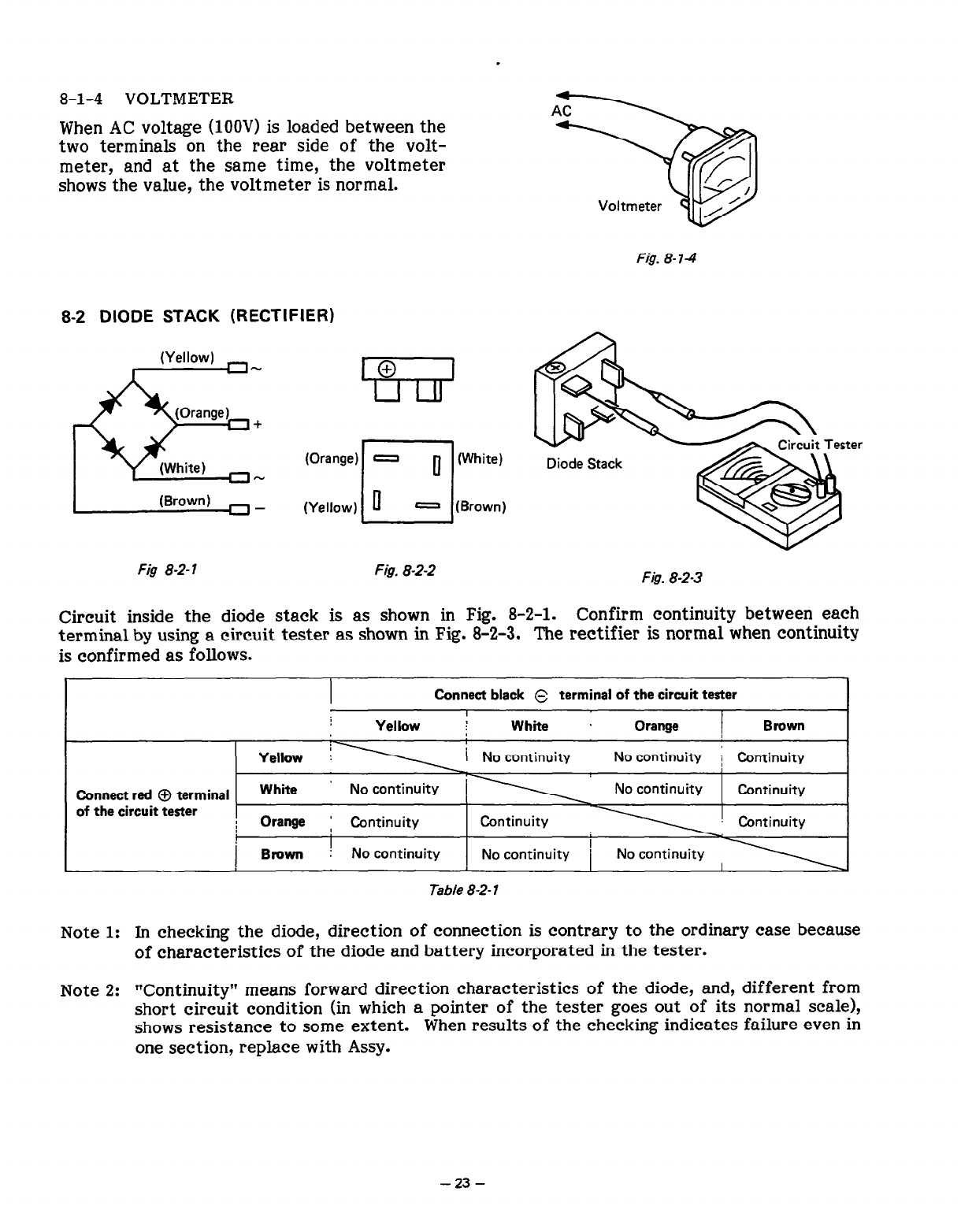
8-l-4 VOLTMETER
When AC voltage (1OOV) is loaded between the
two terminals on the rear side of the volt-
meter, and at the same time, the voltmeter
shows the value, the voltmeter is normal.
Fig. 8-l-4
8-2 DIODE STACK (RECTIFIER)
(Orange) 0 0
cl
(White)
(Yellow) 0 - (Brown)
Fig 8-2-l Fig. 8-2-2 Fis. 8-2-3
Circuit inside the diode stack is as shown in Fig. 8-2-l. Confirm continuity between each
terminal by using a circuit tester as shown in Fig. 8-2-3. The rectifier is normal when continuity
is confirmed as follows.
I
Connect black s terminal of the circuit tester I
I
Yellow ; White . Orange Brown
No continuity ; Continuity
Connect red 0 terminal
of the circuit tester
I
Table 8-2- 1
Note 1: In checking the diode, direction of connection is contrary to the ordinary case because
of characteristics of the diode and battery incorporated in the tester.
Note 2: “Continuity” means forward direction characteristics of the diode, and, different from
short circuit condition (in which a pointer of the tester goes out of its normal scale),
shows resistance to some extent. When results of the checking indicates failure even in
one section, replace with Assy.
- 23 -
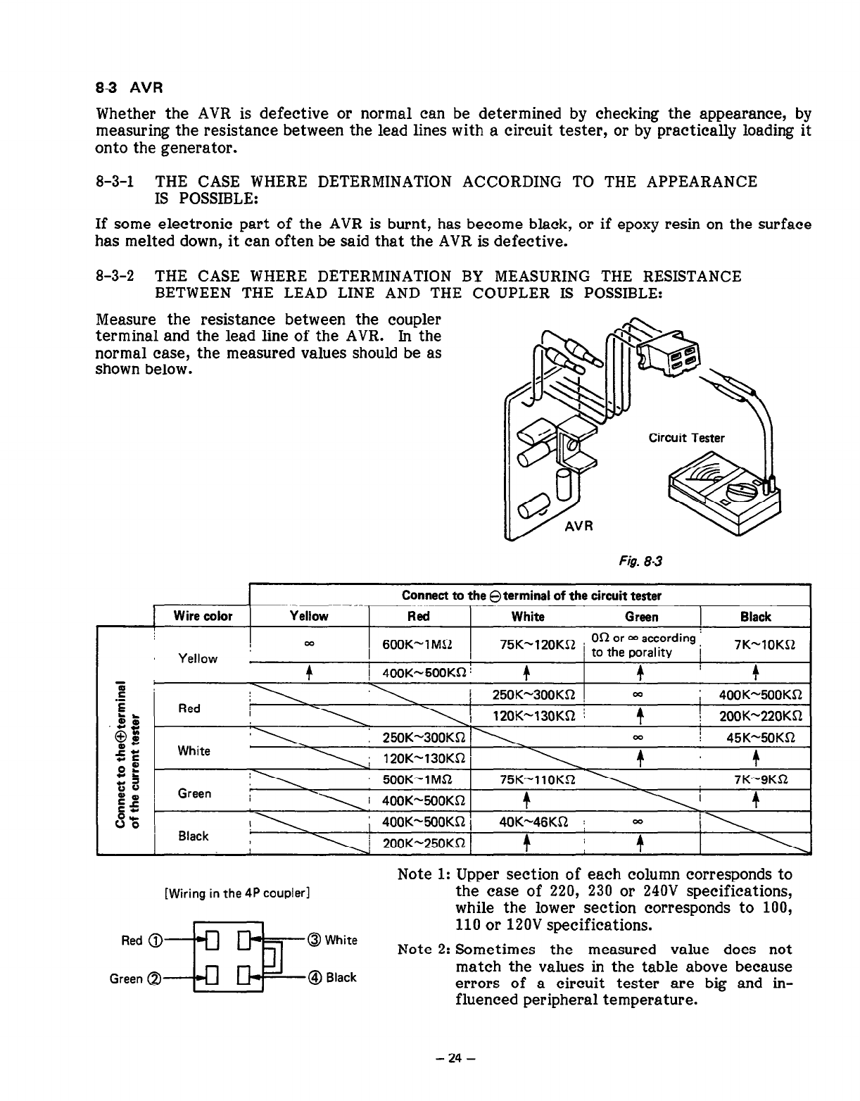
83 AVR
Whether the AVR is defective or normal can be determined by checking the appearance,
by
measuring the resistance between the lead lines with a circuit tester, or by practically loading it
onto the generator.
8-3-l THE CASE WHERE DETERMINATION ACCORDING TO THE APPEARANCE
IS POSSIBLE:
If some electronic part of the AVR is burnt, has become black, or if epoxy resin on the surface
has melted down, it can often be said that the AVR is defective.
8-3-2 THE CASE WHERE DETERMINATION BY MEASURING THE RESISTANCE
BETWEEN THE LEAD LINE AND THE COUPLER IS POSSIBLE:
Measure the resistance between the coupler
terminal and the lead line of the AVR. In the
normal case, the measured values should be as
shown below.
Fig. 83
Wire color Yellow
Connect to the 8 terminal of the circuit tester
Red White Green Black
5
.E
E
.;s
x
@W
W-
fE
OE
CL
t;s
Eg
6%
1 m 1 600K-1MR 1 75K-120KS2
Yellow / ;ft;;
I zr;;;;ding ; 7K-lOKS2
I
4
1 400K-500KR :
4 4
! 4
250K-300KR ! ; 400K-5OOKS2
120K-130KS1 j I
\ 2OOK-220KR
250K-300Kn ,\ 7 45K-5OKR
4
500K-lMS2 75K-110KR \ 7K-9KQ
\ 1 400K-500KS1 4
; 400K-5OOKfi 1 40K-46KQ j =
\ ! 200K-250KS2 1 4 i 4
[Wiring in the 4P coupler]
Red @--
Green @I
@White
@I Black
Note 1: Upper section of each column corresponds to
the case of 220, 230 or 240V specifications,
while the lower section corresponds to 100,
110 or 120V specifications.
Note 2: Sometimes the measured value does not
match the values in the table above because
errors of a circuit tester are big and in-
fluenced peripheral temperature.
- 24 -
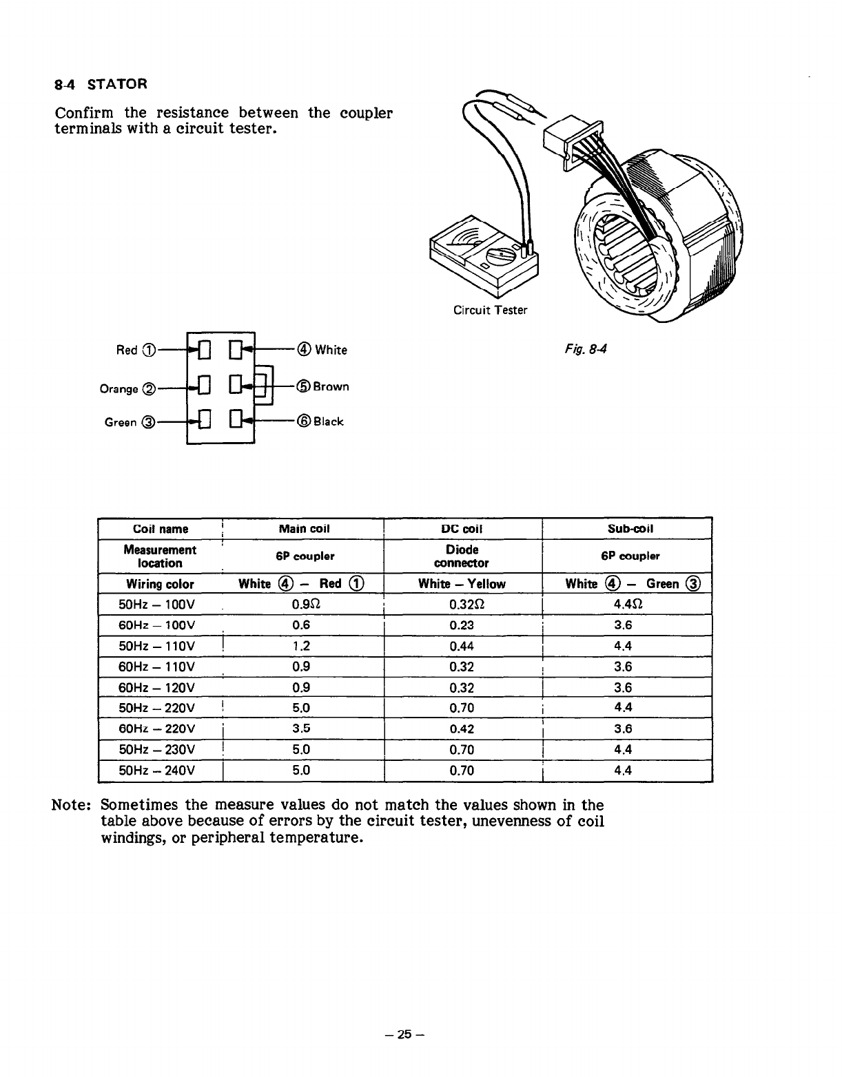
84 STATOR
Confirm the resistance between the coupler
terminals with a circuit tester.
Red 3+-J a-@ White
Orange Q
Green @
OB rown
@Black
Circuit Tester
F&. 8-4
Coil name I Main coil DC coil Sub-coil
Measurement ’ Diode
location 6P coupler connector 6P coupler
Wiring color White @ - Red @ 1 White - Yellow White @ - Green @
50Hz - IOOV 0.951 0.32Q 4.452
60Hz - 1oov 0.6 0.23 3.6
50Hz - I IOV ! 1.2 0.44 I 4.4
60Hz - 1 IOV 0.9 I
0.32 3.6
60Hz - 120v 0.9 0.32 I 3.6
50Hz - 220V ! 5.0 0.70 I 4.4
60HZ - 220V i 3.5 0.42 3.6
50Hz - 230V ! 5.0 0.70 4.4
50Hz - 240V 5.0 0.70 I 4.4
Note: Sometimes the measure values do not match the values shown in the
table above because of errors by the circuit tester, unevenness of coil
windings, or peripheral temperature.
- 25 -
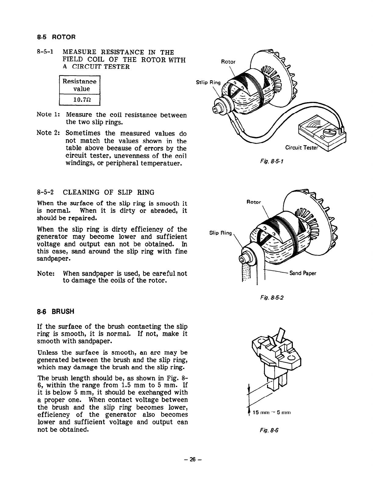
8-5 ROTOR
8-5-l MEASURE RESISTANCE IN THE
FIELD COIL OF THE ROTOR WITH
A CIRCUIT TESTER
Resistance
El
value
10.7J-z
Note 1: Measure the coil resistance between
the two slip rings.
Note 2: Sometimes the measured values do
not match the values shown in the
table above because of errors by the
circuit tester, unevenness of the coil
windings, or peripheral temperatuer.
8-5-2 CLEANING OF SLIP RING
When the surface of the slip ring is smooth it
is normal. When it is dirty or abraded, it
should be repaired.
When the slip ring is dirty efficiency of the
generator may become lower and sufficient
voltage and output can not be obtained. In
this case, sand around the slip ring with fine
sandpaper.
Note: When sandpaper is used, be careful not
to damage the coils of the rotor.
Stlip
Slip Ring
F&T 8-S 1
Fig. 8-5-2
8-6 BRUSH
If the surface of the brush contacting the slip
ring is smooth, it is normal. If not, make it
smooth with sandpaper.
Unless the surface is smooth, an arc may be
generated between the brush and the slip ring,
which may damage the brush and the slip ring.
The brush length should be, as shown in Fig. 8-
6, within the range from 1.5 mm to 5 mm. If
it is below 5 mm, it should be exchanged with
a proper one. When contact voltage between
the brush and the slip ring becomes lower,
efficiency of the generator also becomes
lower and sufficient voltage and output can
not be obtained.
5mm-5mm
Fig. 8-6
- 26 -
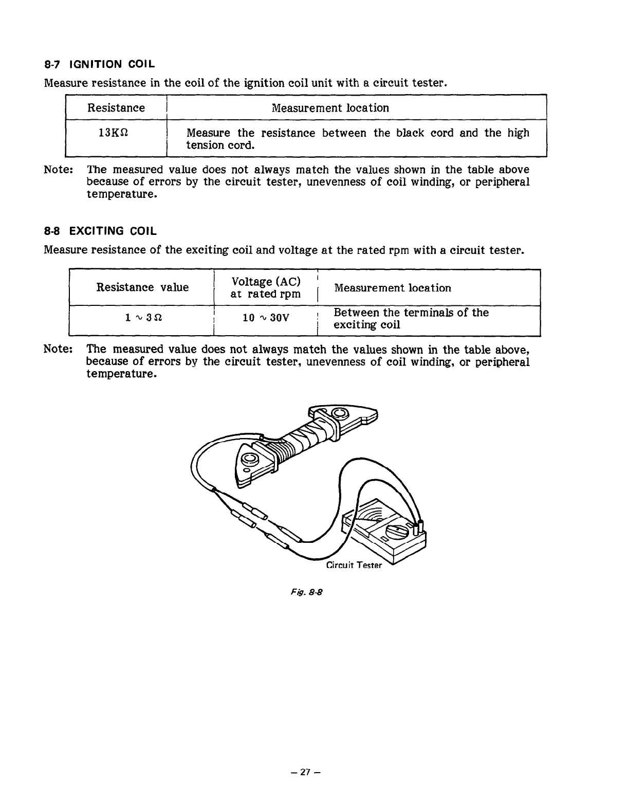
8-7 IGNITION COIL
Measure resistance in the coil of the ignition coil unit with a circuit tester.
!
Resistance (
I Measurement location
13K!G?
i
Measure the resistance between the black cord and the high
tension cord.
Note: The measured value does not always match the values shown in the table above
because of errors by the circuit tester, unevenness of coil winding, or peripheral
temperature.
8-8 EXCITING COIL
Measure resistance of the exciting coil and voltage at the rated rpm with a circuit tester.
Resistance value ( Voltage (AC) :
I at rated rpm 1 Measurement location
I
I
10 Q 3ov ; Between the terminals of the
I i exciting coil
Note: The measured value does not always match the values shown in the table above,
because of errors by the circuit tester, unevenness of coil winding, or peripheral
temperature.
-
27
-
9. DISASSEMBLY AND ASSEMBLY
9-l PREPARATION AND REMARKS
(1) Be sure to remember the locations of individual parts when disassembling the generator so
that the generator can be reassembled correctly. Tie tags with the necessary information
written in to facilitate easier and smoother reassembly.
(2) For more convenience, group the related parts and store them in the same box.
(3) To prevent bolts and nuts from being misplaced or installed incorrectly, place them
temporarily at their original positions.
(4) Handle the disassembled parts with care and clean them before reassembly using neutral
cleaning oil. (Be careful not to clean electric parts with neutral cleaning oil.)
(5) Use proper tools for disassembly/assembly.
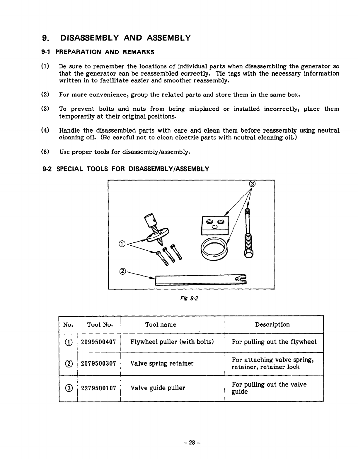
9-2 SPECIAL TOOLS FOR DISASSEMBLY/ASSEMBLY
Fig 9-2
No. i Tool No. !
Tool name Description
2099500407 1 Flywheel puller (with bolts) For pulling out the flywheel
I !
@ 1 2079500307 i Valve spring retainer For attaching valve spring,
retainer, retainer lock
I
2279500107 I Valve guide puller For pulling out the valve
i guide
I ,
-
28
-
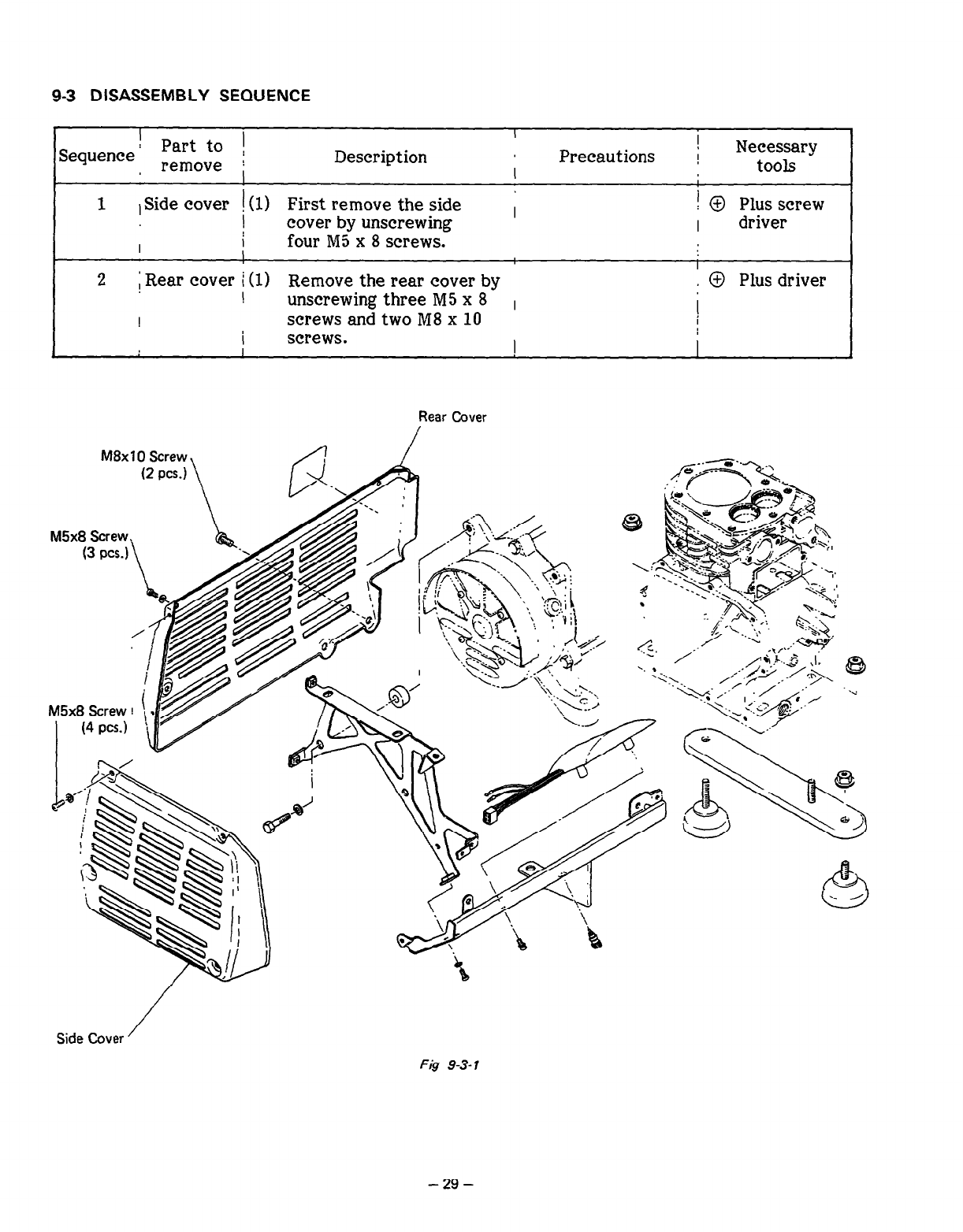
9-3 DISASSEMBLY SEQUENCE
I
Sequence
I Part to !
, remove j Description
1 I
Precautions ! Necessary
I tools
1 1 Side cover ! (1) First remove the side i I 0 Plus screw
! cover by unscrewing I driver
I I four M5 x 8 screws.
! I
2 ; Rear cover i (1) Remove the rear cover by , @ Plus driver
! unscrewing three MS x 8 ,
! screws and two M 8 x 10 !
I
I screws. I I
Rear Cover
M8x 10 Screw,
Side Cover /
Fig 9-3-l
- 29 -
’ Part to !
I I
Sequence ] remOve :
Description I Precautions Necessary
I I I ; tools
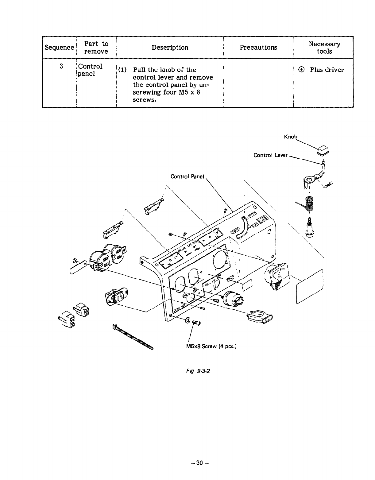
3 icontrol I(l) Pull the knob of the I
1 panel 1 @ Plus driver
I control lever and remove
I I the control panel by un- ! I
I I screwing four M5 x 8 I
screws. I
I I I
I I
Knob
L
Control Lever by
,
Fig 9-3-2
- 30 -
1 Part to
I
Sequence 1 j
remove 1 Description
i
Precautions I Necessary
tools
I
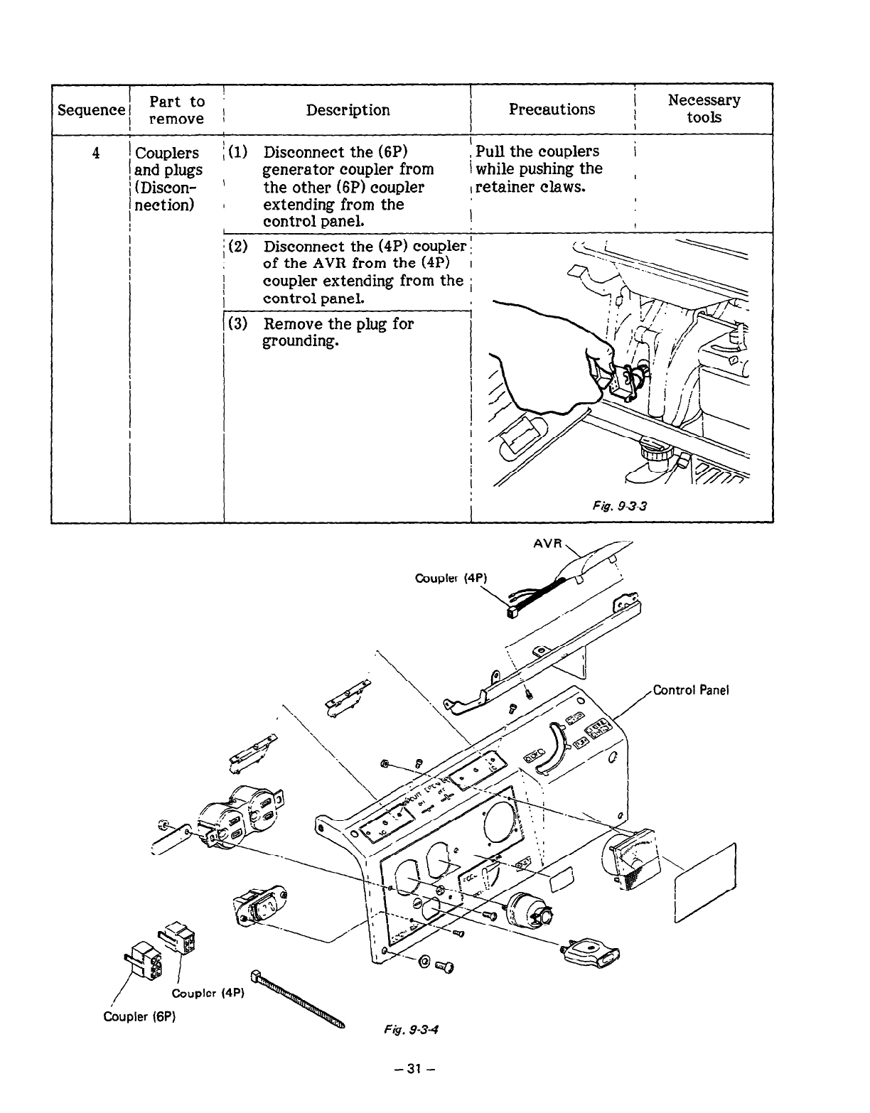
4 ( Couplers Disconnect the (6P) i
1 and plugs i (1) , Pull the couplers
generator coupler from ! while pushing the ,
, (Discon- ’ the other (6P) coupler I retainer claws.
j nection) 1
I extending from the
control panel. !
I
/ (2) Disconnect the (4P) coupler I , I
of the AVR from the (4P) I
coupler extending from the ;
control panel.
i
(3) Remove the plug for
grounding.
i
i I
I I
I !
1
I I I
Fig. 9-3-3
Sequence
I Part to
remove j Description
I
Precautions I Necessary
I tools
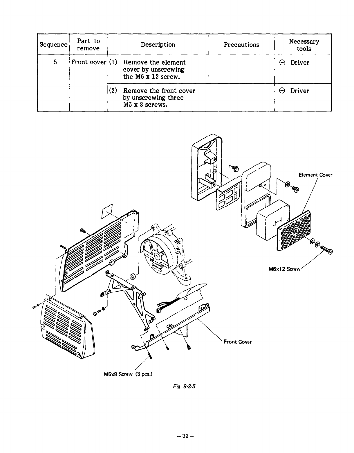
5 iFront cover (1) Remove the element 0 Driver
( cover by unscrewing
the M6 x 12 screw. 1
I(2) Remove the front cover 1 I @ Driver
by unscrewing three ! I
I M5 x 8 screws.
M6x12 Screw ’
Front Cover
/
M5x8 Screw (3 PCS.)
FJ$. 9-3-5
-32-
1 Part to ’
Sequence j remOve Description
I
Precautions j Necessary
I tools
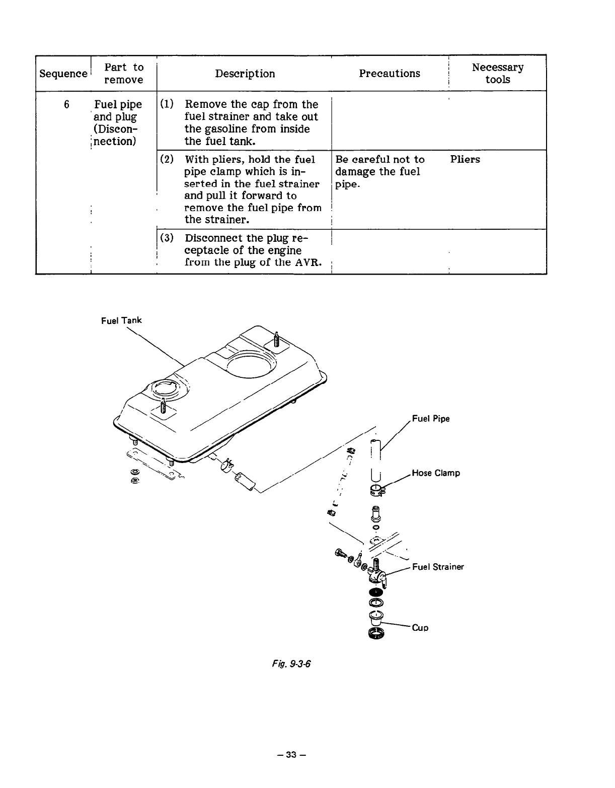
6 Fuel pipe (1) Remove the cap from the ’
‘and plug fuel strainer and take out
(Discon-
i nection) the gasoline from inside
the fuel tank.
(2) With pliers, hold the fuel Be careful not to Pliers
pipe clamp which is in- damage the fuel
serted in the fuel strainer pipe.
and pull it forward to
remove the fuel pipe from !
the strainer. I
I(3) Disconnect the plug re- 1
ceptacle of the engine
from the plug of the AVR. ;
I
Pipe
Clamp
Strainer
FI& 93-6
-33-
Sequence, Part to
remove
I Description Precautions Necessary
tools
I
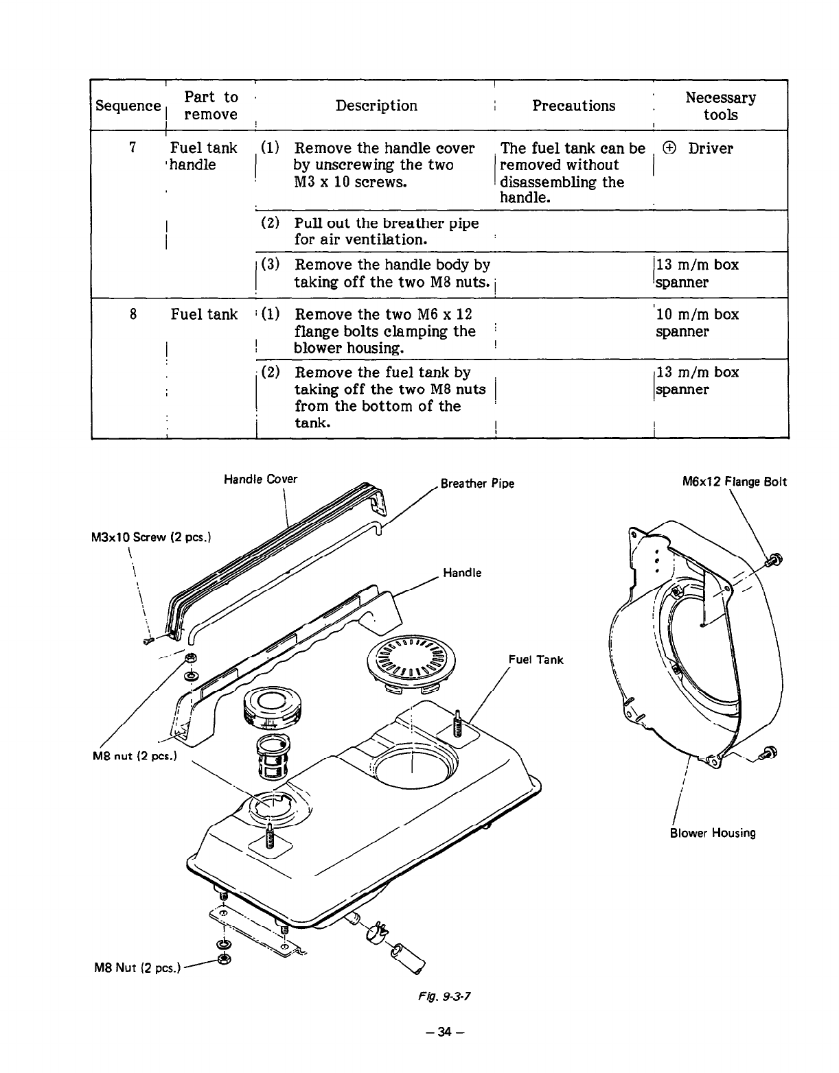
7 Fuel tank (1) Remove the handle cover The fuel tank can be , @ Driver
I handle by unscrewing the two removed without
M3 x 10 screws. I disassembling the I
handle.
(2) Pull out the breather pipe : for air ventilation.
I (3) Remove the handle body by 113 m/m box
taking off the two M8 nuts. i Lpanner
8
Fuel tank i (1) Remove the two M6 x 12 ‘10 m/m box
flange bolts clamping the I spanner
!
I
blower housing. I
(2) Remove the fuel tank by
taking off the two M8 nuts
from the bottom of the / 13 m/m box
spanner
’
I tank. I I
Handle Cover
M3xlO Screw (2 PCS.)
\
/
M8 nut (2 pcs ) -7, @gfiJpcp
2
piy
\
M6xl2 Flange Bolt
\
Tank
I
Blower Housing
Fig. 9-3-7
1 1
Sequence Part to ’ Description , Precautions Necessary
remove tools
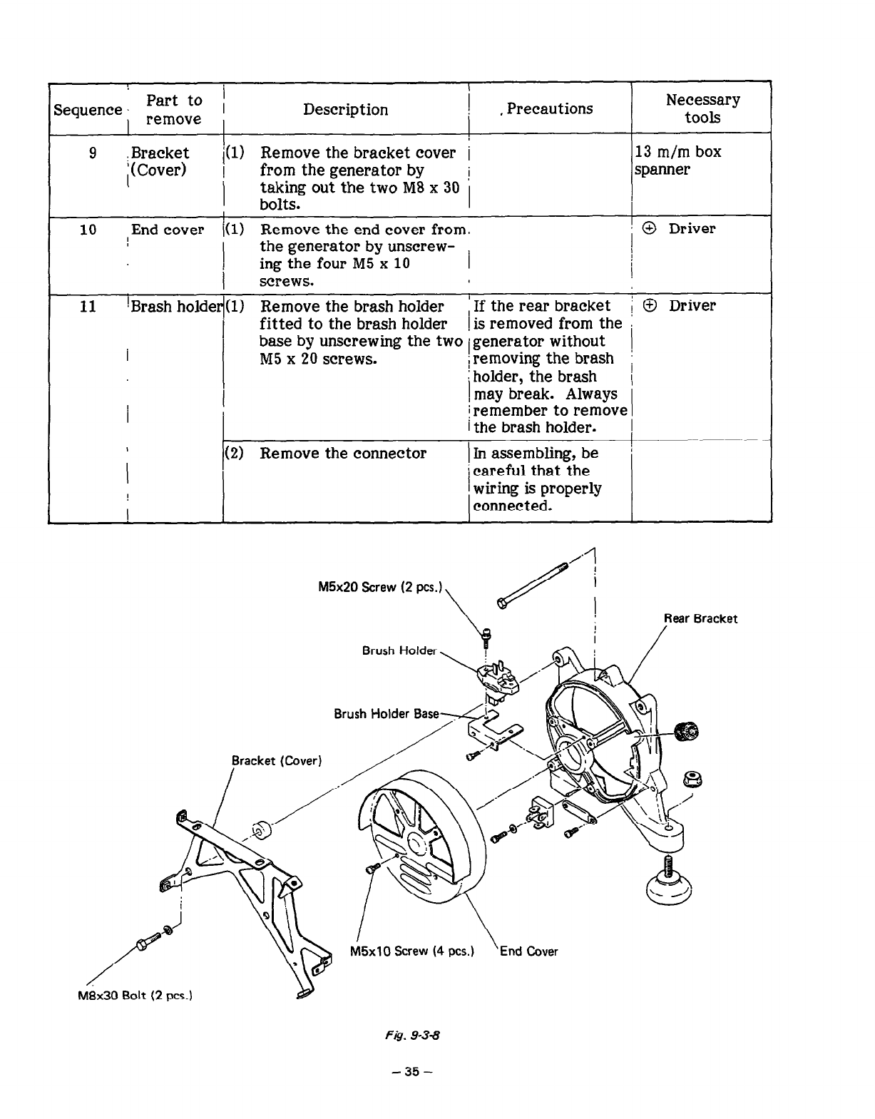
9 i(l)
j$Ez; 1 Remove the bracket cover i 13 m/m box
from the generator by i spanner
’
1 taking out the two M8 x 30
bolts.
10 End cover /(l) Remove the end cover from.
the generator by unscrew- i i @ Driver
ing the four M5 x 10 I I
I
screws.
11 IBrash holder((1) Remove the brash holder ‘If the rear bracket / @ Driver
I fitted to the brash holder 1 is removed from the :
I base by unscrewing the two igenerator without
jremoving the brash !
M5 x 20 screws. holder, the brash i
I \
may break. Always
!
I i remember to remove
/the brash holder. 1
1 (2) Remove the connector ’
I
) In assembling, be
i careful that the
I 1 wiring is properly
! connected.
M5x20 Screw (2 PCS.)
Brush Holder
Rear Bracket
Brush Holder Basedi>
Bracket (Cover)
I
M5xlO Screw (4 PCS.) \ End Cover
Fig. 9-3-8
-35-
I
j Part to 1
Sequence I remOve Description Precautions j Necessary
tools I
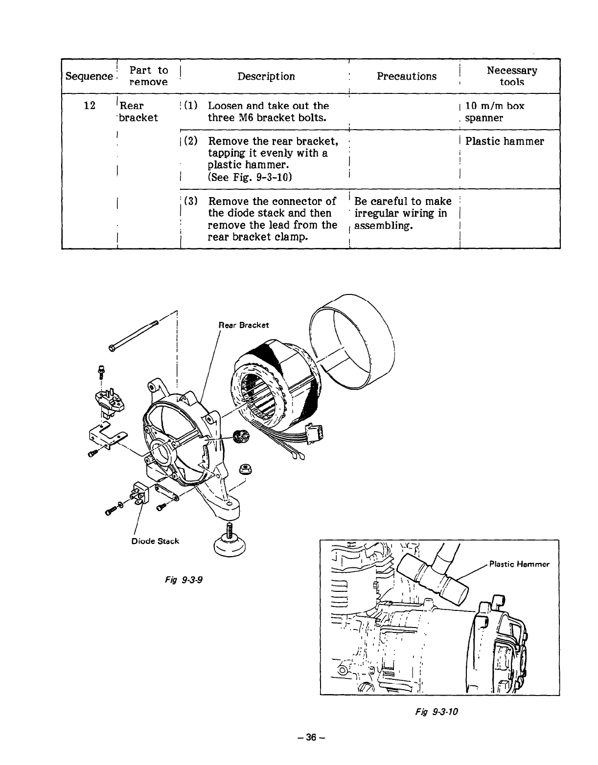
12 ’ Rear
‘bracket
I
j (1) Loosen and
take
out the 1 10 m/m box
three M6 bracket bolts. , spanner
i (2) Remove the rear bracket, a
tapping it evenly with a ’
plastic hammer.
I (See Fig. g-3-10) I
i Plastic hammer
I
I
I
/ (3) Remove the connector of ’ Be careful to make j
the d&e stack and then irregular wiring in (
remove the lead from the , assembling. I
I
I rear bracket clamp. I 1
Rear Bracket
/
Diode Stack
Fig 9-3-9
Plastic Hammer
-36-
I
I I
Sequence I rpearfito~~ i Description I I
Precautions Necessary
tools
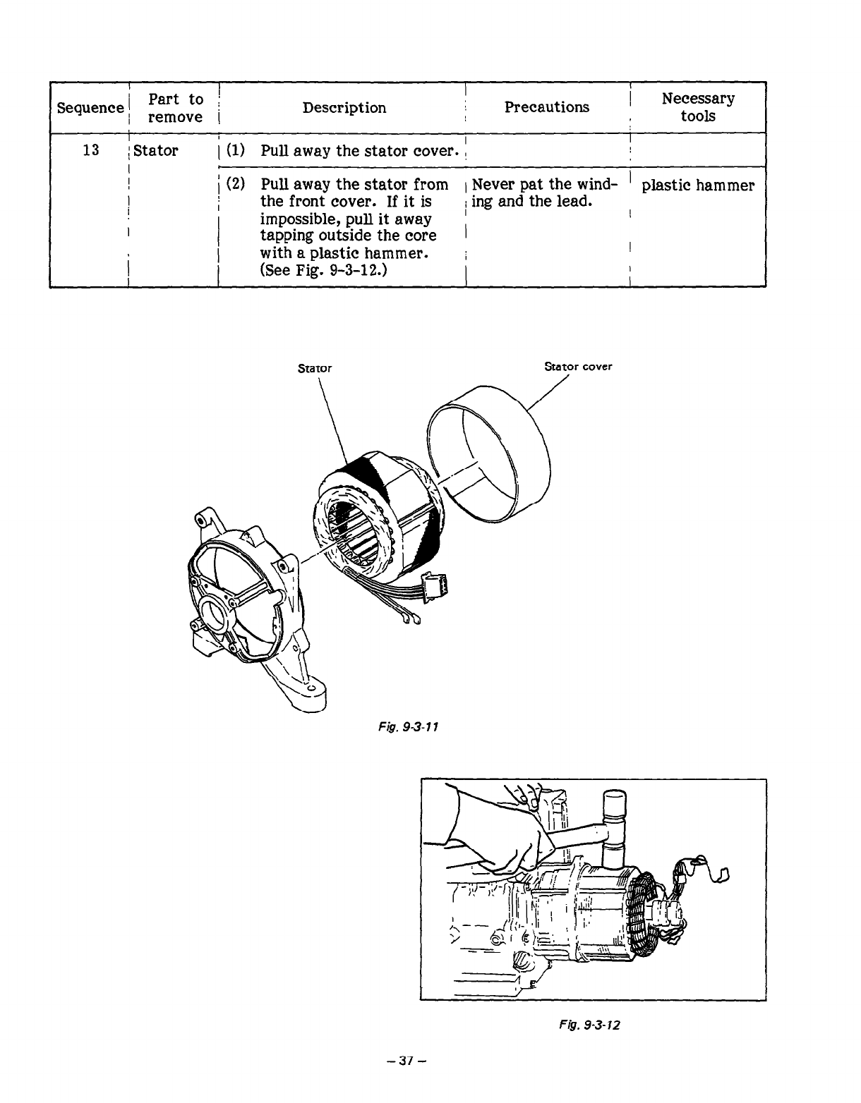
13 1 Stator
I
I
!
1
I
c
(1) Pull away the stator cover. i
(2) Pull away the stator from 1 Never pat the wind- ’ plastic hammer
the front cover. If it is
impossible, pull it away / ing and the lead. I
tapping outside the core 1
with a plastic hammer. ; !
(See Fig. 9-3-12.) I I
I
Stator Stator cover
Fig. 9-3-l 1
F&. 9-3-12
Sequence , Part to ’
remove I Description
I
Precautions Necessary
tools
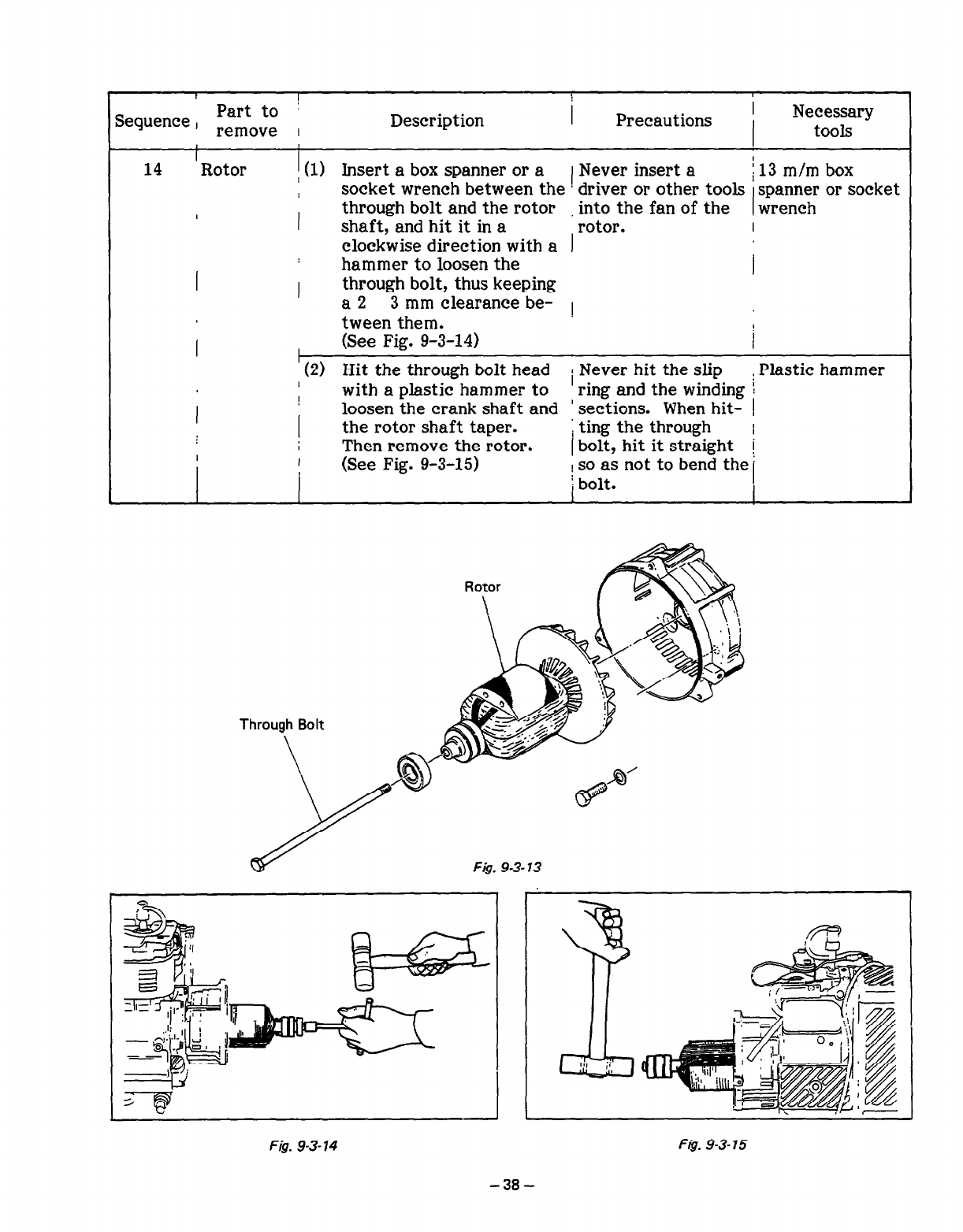
14 ‘Rotor i (1) Insert a box spanner or a 1 Never insert a /13 m/m box
socket wrench between the driver or other tools spanner or socket
wrench
I
through bolt and the rotor into the fan of the
I shaft, and hit it in a rotor. I
clockwise direction with a
I
hammer to loosen the I
I through bolt, thus keeping
a2 3 mm clearance be- 1
tween them.
(See Fig. 9-3-14) I
,
’ (2) Hit the through bolt head / Never hit the slip : Plastic hammer
I with a plastic hammer to ring and the winding I
loosen the crank shaft and ’ sections. When hit-
! i
the rotor shaft taper. 1 ting the through I
I Then remove the rotor. I bolt, hit it straight
I (See Fig. 9-3-15) [
I j so as not to bend the ’
; bolt. I
Through Bolt
Fig. 9-3- 13
siw‘ , ,_,
*
iI
L$z
2 .;I _
- ,ea
I=‘~ !jI-: ,~-’ ‘1
~-~~~i ~,
L , il
,f!jF
Fi@. 9-3-14 F&. 9-3-15
-38-
! Part to /
Sequence j remove ’ Description
I I
i
Precautions : Necessary
tools
I
I
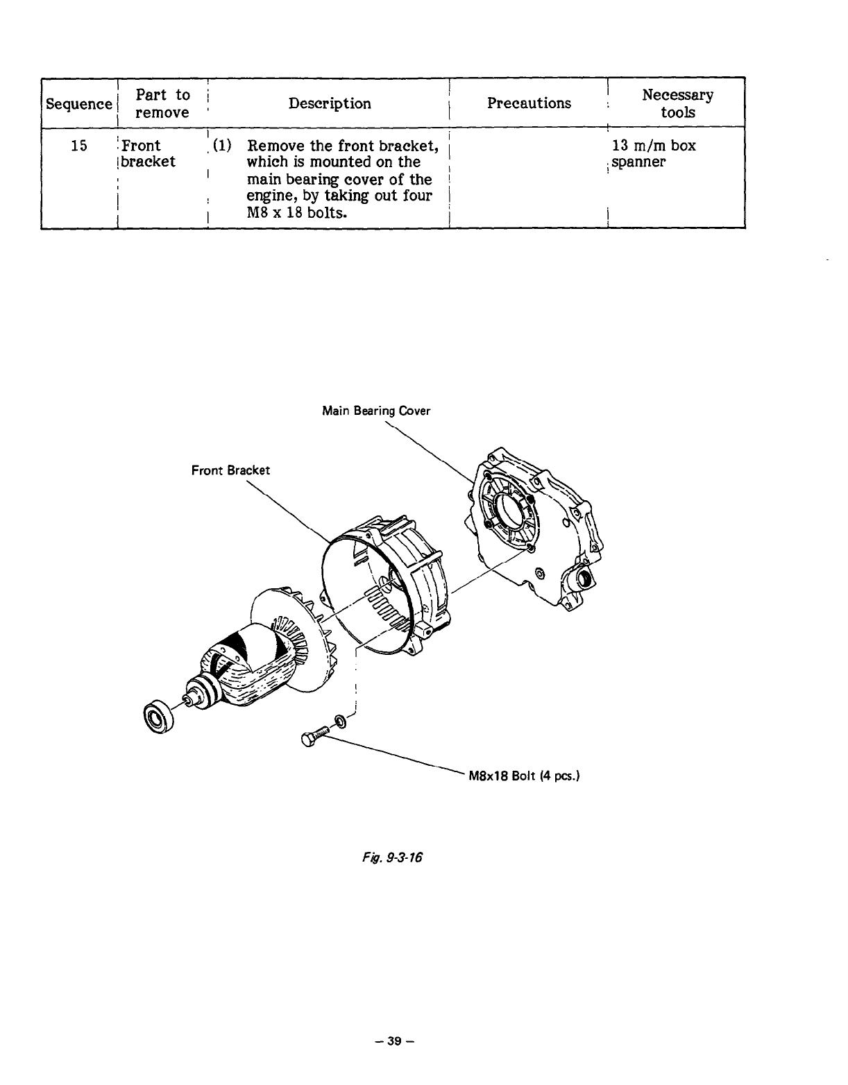
15 j Front (1) Remove the front bracket, i 13 m/m box
i bracket which is mounted on the
I ,
I main bearing cover of the / spanner
I
1 engine, by taking out four I
I I MS x 18 bolts. / /
Main Bearing Cover
Front Bracket
Fig. 9-3- 76
-39-
I
Part to i
Sequence ! remOve ;
I Description I
I
I
Precautions I Necessary
tools
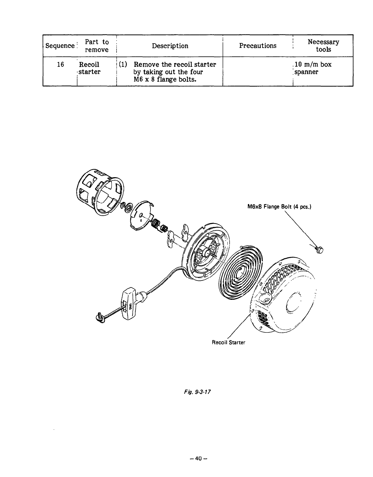
16 Recoil j(l) Remove the recoil starter -10 m/m box
mstarter by taking out the four 1 spanner
1 M6 x 8 flange bolts. I
1 I
RecoilvStarter
Fig. 9-3- 77
-40-
, 1
j
I
Sequence 1
Part to Description Precautions 1 Necessary
remove j I tools
I I
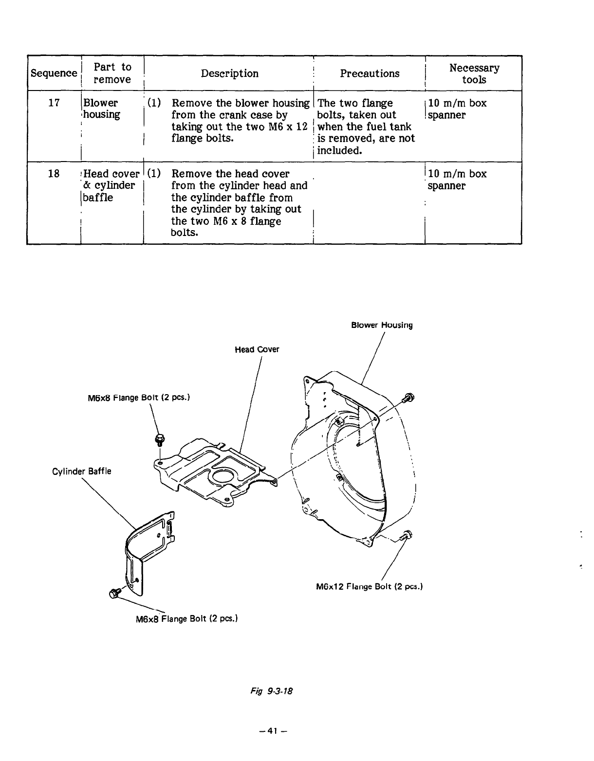
17 Blower i (1) Remove the blower housing The two flange ’ 10 m/m box
1 housing from the crank case by bolts, taken out
taking out the two M6 x 12 1 when the fuel tank , spanner
I I flange bolts. i is removed, are not
I I / included.
18 !Head cover I(l) Remove the head cover I10 m/m box
‘& cylinder j from the cylinder head and spanner
baffle / the cylinder baffle from
the cylinder by taking out
the two M6 x 8 flange ,
bolts. I
Blower Housing
M6xB Flange Bolt (2 PCS.)
\
M6x12 Flange Bolt (2 PCS.)
M6x8-kange Bolt (2 pcs.1
Fig 9-3-78
-41-
I
Description !
I Precautions . Necessary
tools
I
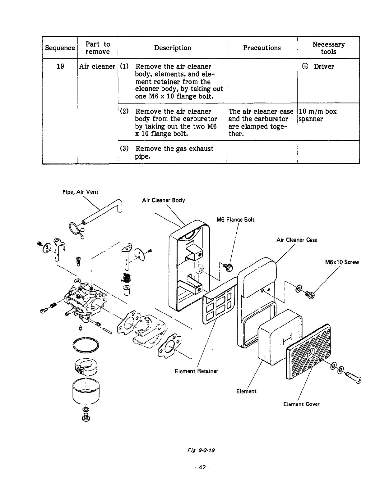
Air cleaner : (1) Remove the air cleaner @ Driver
body, elements, and ele-
ment retainer from the
cleaner body, by taking out I
one M6 x 10 flange bolt.
I
i (2) Remove the air cleaner The air cleaner case ! 10 m/m box
body from the carburetor and the carburetor /spanner
by taking out the two M6 are clamped toge-
x 10 flange bolt. ther.
(3) Remove the gas exhaust ,
pipe. I
Pipe, Air Vent
Air Cleaner Body
M6 Flange Bolt
I
I Air Cleaner Case
I
Element Retainer
M6xlO Screw
/
Element
/
Element Cover
Fig 93-79
-42-
I
Sequence 1 Part to j
- remove ! Description
I
Precautions Necessary
tools
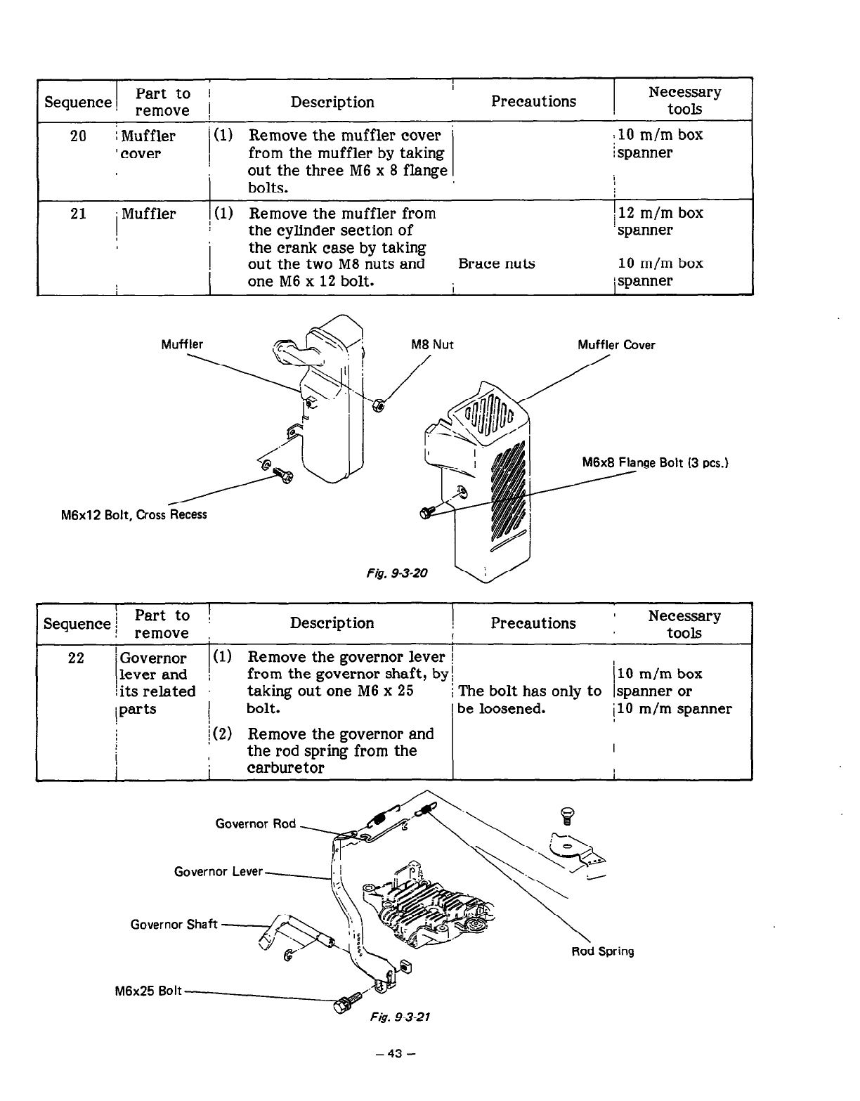
20 i Muffler j (1) Remove the muffler cover ’ :lO m/m box
I cover ! from the muffler by taking i spanner
i
out the three M6 x 8 flange
bolts.
21 Muffler I(1) Remove the muffler from 112 m/m box
the cylinder section of ’ spanner
the crank case by taking
out the two M8 nuts and Brace nuts 10 m/m box
one M6 x 12 bolt.
I I j spanner
Muffler Cover
nge Bolt (3 PCS.)
M6x12 Bolt, Cross Recess
I Part to 1
Sequence j remOve
Description Precautions ’ Necessary
, tools
22 ’ Governor
lever and
! its related
i parts
l-
(1) Remove the governor lever j
from the governor shaft, by: 110 m/m box
taking out one M6 x 25 I The bolt has only to Ispanner or
bolt. i be loosened. j10 m/m spanner
(2) Remove the governor and
the rod spring from the I
. .
I carburetor I
Governor Lever
1 Part to ’ I
Sequence 1 remove : Description Precautions 1 Necessary
tools
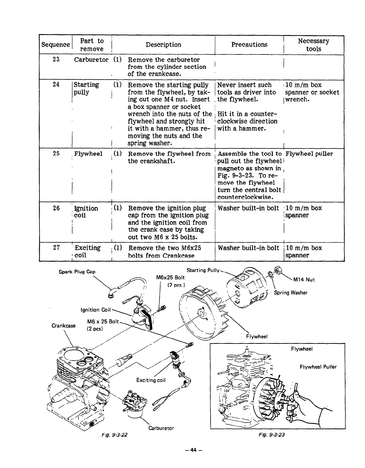
23
24
Carburetor (1) Remove the carburetor I
from the cylinder section ’ 1
of the crankcase.
Starting (1) Remove the starting pully
PUllY j from the flywheel, by tak-
ing out one M4 nut. Insert
a box spanner or socket
wrench into the nuts of the
flywheel and strongly hit !
Never insert such 810 m/m box
tools as driver into spanner or socket
the flywheel. /wrench.
Hit it in a counter-
clockwise direction
it with a hammer, thus re- with a hammer.
moving the nuts and the
I spring washer.
25 Flywheel (1) Remove the flywheel from i Assemble the tool to Flywheel puller
the crankshaft .
! !
I
26 i &cocci*n
. i (1) Remove the ignition plug
cap from the ignition plug
I I
I I and the ignition coil from
the crank case by taking
pull out the flywheel
magneto as shown in
Fig. 9-3-23. To re-
move the flywheel
turn the central bolt
counterclockwise.
I out two M6 x 25 bolts.
27 ’ Exciting Remove the two M6x25
1 coil j (1) bolts from Crankcase
I I
Washer built-in bolt 10 m/m box
: spanner
Washer built-in bolt / 10 m/m box
1 spanner
Spark Plug Cap
Ignition Coil 1
Crankcase M6 x 25 Bc
,-I ---I
/ - A-- l
Flywheel
Flywheel Puller
Carburetor I
Fig. 9-3-22 Fig. 9-3-23
-44-
1 Part to
Sequence.
1
remOve !
Description I Precautions Necessary
tools
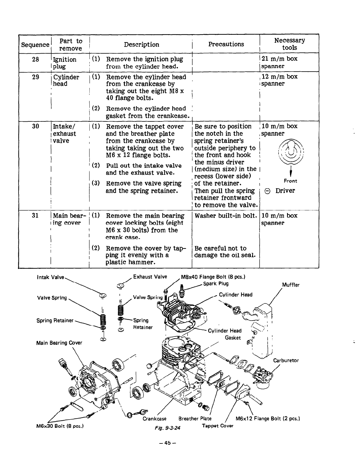
28 I Ignition I (1) Remove the ignition plug 1 ! 21 m/m box
1 plug from the cylinder head. i spanner
29 / Cylinder I ! 12 m/m box
, head j(1) Remove the cylinder head
from the crankcase by i spanner
I taking out the eight M8 x ! 1
1 40 flange bolts.
I(2) Remove the cylinder head I I
I
I gasket from the crankcase. ,
30 / Intake/ i (1) Remove the tappet cover I Be sure to position i 10 m/m box
1 exhaust , and the breather plate / the notch in the : spanner
lvalve , from the crankcase by 1 spring retainer’s ’
I ! taking taking out the two outside periphery to
) M6 x 12 flange bolts. [ the front and hook i
I ! (2) Pull out the intake valve ’ the minus driver
I and the exhaust valve. j (medium sizej in the ;
, recess (lower side) i
:
, (3) Remove the valve spring Front
!
I
and the spring retainer. i of the retainer.
Then pull the spring
I [ 0 Driver
I retainer frontward
1 j to remove the valve. n
i
31 1 Main bear- / (1) Remove the main bearing Washer built-in bolt. 10 m/m box
I ing cover ! cover locking bolts (eight
I 1 M6 x 30 bolts) from the , spanner
I
I crank case. I
i (2) 1
Remove the cover by tap- ! Be careful not to
I ; ping it evenly with a I damage the oil seal.
plastic hammer.
lntak Valve, , Exhaust Valve , M8x40 Flange Bolt (8 PCS.)
Muffler
/
Flange Bolt (2 PCS.)
M6x30 Bolt (8 PCS.) Fig. 9-3-24 Tappet Cover
I
I I
Sequence Part to
remove Description
!
Precautions i Necessary
tools
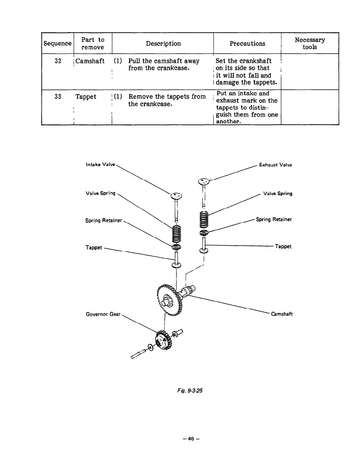
32 i Camshaft (1) Pull the camshaft away I
Set the crankshaft !
from the crankcase. ; on its side
SO
that i
j it will not fall and b
i
damage the tappets.
33 Tappet i (1) Remove the tappets from
the crankcase. ; ~~~a~s~~a~~ E:dthe
tappets to distin- I
i guish them from one 1
Intake Valve \
Valve Spring,
i i
L
Governor Gear, Camshaft
F&T. 9-3-25
-46-
r
Part to
Wuence remOve
Description Precautions Necessary
tools
,
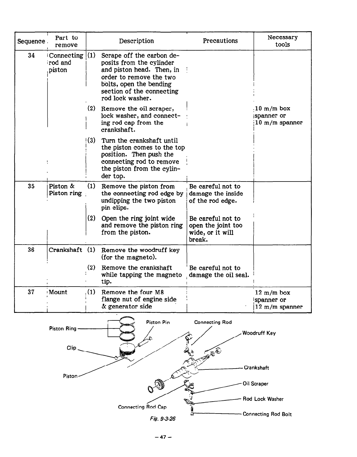
34 i
Connecting i(l) Scrape off the carbon de-
: rod and posits from the cylinder
: piston and piston head. Then? in j
order to remove the two
bolts, open the bending
section of the connecting
rod lock washer.
(2) Remove the oil scraper, 1
! lock washer, and connect- I
1 ing rod cap from the
crankshaft.
:lO m/m box
i spanner or
/ 10 m/m spanner
35
!(3) Turn the crankshaft until
I
I the piston comes to the top
I
position. Then push the
!
connecting rod to remove j I
I
the piston from the cylin- I
der top. I
I
‘Piston bc (1) Remove the piston from 1 Be careful not to
! Piston ring : the connecting rod edge by i damage the inside i
undipping the two piston i of the rod edge.
pin clips.
(2) Open the ring joint wide Be careful not to
and remove the piston ring open the joint too i
i
from the piston. wide, or it will
break.
36
37
Crankshaft (1) Remove the woodruff key
(for the magneto).
:(2) Remove the crankshaft i Be careful not to !
while tapping the magneto i damage the oil seal. I
tip. I
i Mount ;(l) Remove the four M8 : ‘12 m/m box
flange nut of engine side i
i & generator side I ! spanner or
I ) 12 m/m spanner
Piston Ring
Clip
Piston
/
Connecting Rod Cap
<--- Rod Lock Washer
;‘;
ti
G
F&. 9-3-26 Connecting Rod Bolt
-47-
9-4 ASSEMBLY PROCEDURE
n
Precautions in assembly
(1)
(2)
(3)
(4)
(5)
(6)
(7)
(8)
(9)
Thoroughly clean each part. When cleaning, take special care with the piston, cylinder,
crankshaft, connecting rod, and each bearing.
Be sure to completely scrape off th carbon deposits on the cylinder head and piston head.
Also, thoroughly remove carbon deposits from each piston ring groove.
Check whether the lip of each oil seal is damaged or not, and if damaged, replace it with a
new one. Also, while assembling, apply lubricating oil to the lip of each seal.
Replace the gaskets and other similar items with new ones.
Check the keys, pins, bolts, nuts etc., and replace them, if necessary, with new ones.
Apply torque, according to the specified rate, to those sections where the torque is rated.
Apply lubricating oil to rotating and sliding parts when they are assembled.
Check the clearance of each part prior to assembly and adjust them if necessary.
When each of the main components
have
been assembled, turn each one
by
hand and check
for smoothness of rotation and unusual noise.
-48-
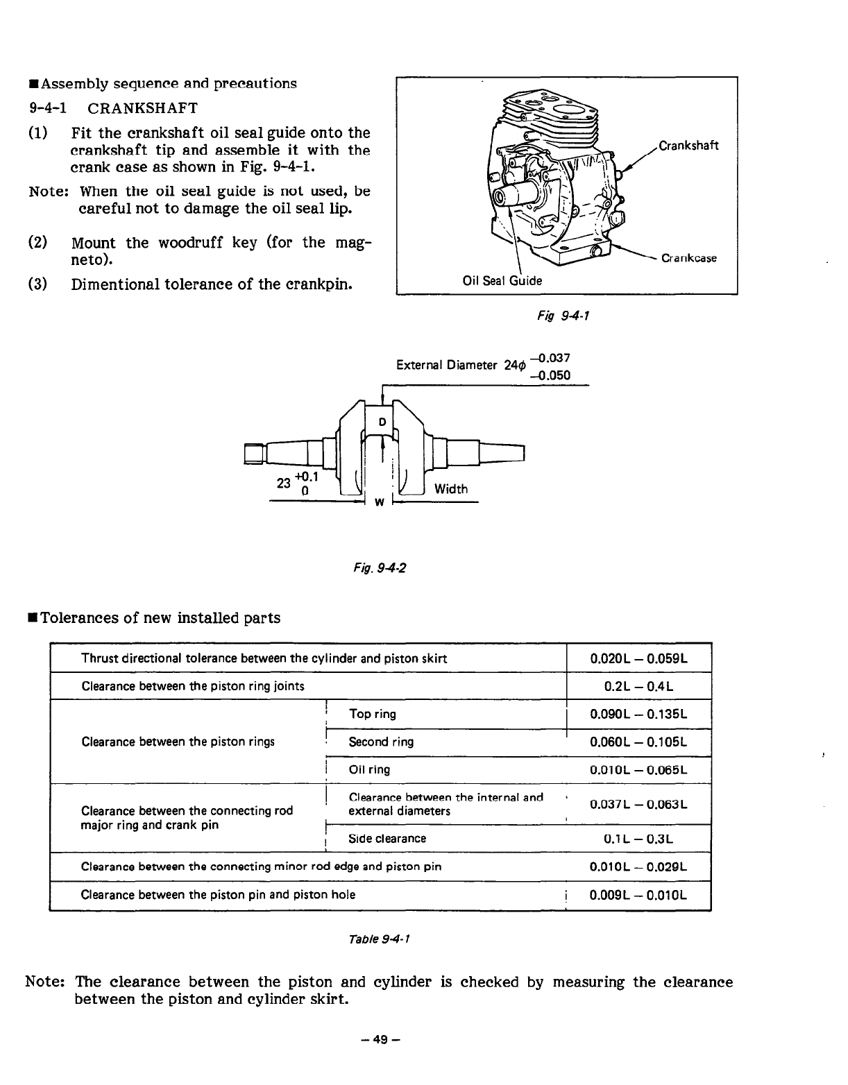
HAssembly sequence and precautions
9-4-l CRANKSHAFT
(1) Fit the crankshaft oil seal guide onto the
crankshaft tip and assemble it with the
crank case as shown in Fig. 9-4-l.
No
te: When the oil seal guide is not used, be
careful not to damage the oil seal lip.
(2)
(3)
Mount the woodruff key (for the mag-
neto).
Dimentional tolerance of the crankpin.
.Crankshaft
Crankcase
Oil Seal Guide
External Diameter 24~) Z-03;
I
I
Fig. 942
WTolerances of new installed parts
I
Thrust directional tolerance between the cylinder and piston skirt 0.02OL - 0.059L
Clearance between the piston ring joints 0.2L - 0.4L
1
i Top ring 0.09OL - 0.135L
Clearance between the piston rings ! Second ring 0.060L - 0.105L
I
/ Oil ring O.OlOL - 0.065L
Clearance between the connecting rod
major ring and crank pin
1 Clearance between the internal and s
’ external diameters 0.037 L - 0.063 L
1 Side clearance 0.1 L - 0.3L
Clearance between the connecting minor rod edge and piston pin O.OlOL - 0.029L
Clearance between the piston pin and piston hole
i
0.009L - 0.01 OL
Table 94 7
Note: The clearance between the piston and cylinder is checked by measuring the clearance
between the piston and cylinder skirt.
-49-
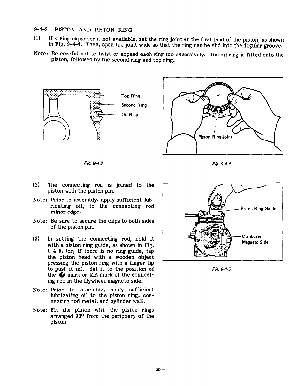
9-4-2 PISTON AND PISTON RING
(1) If a ring expander is not available, set the ring joint at the first land of the piston, as shown
in Fig. 9-4-4. Then, open the joint wide so that the ring can be slid into the fegular groove.
Note: Be careful not to twist or expand each ring too excessively. The oil ring is fitted onto the
piston, followed by the second ring and top ring.
F&. 9-43
Top Ring
Second Ring
Oil Ring
Fig. 9-4-4
(2) The connecting rod is joined to the
piston with the piston pin.
Note: Prior to assembly, apply sufficient lub-
ricating oil, to the connecting rod
minor edge.
Note: Be sure to secure the clips to both sides
of the piston pin.
(3) In setting the connecting rod, hold it
with a piston ring guide, as shown in Fig.
9-4-5, (or, if there is no ring guide, tap
the piston head with a wooden object
pressing the piston ring with a finger tip
to push it in). Set it to the position of
the @ mark or MA mark of the connect-
ing rod in the flywheel magneto side.
Note: Prior to assembly, apply sufficient
lubricating oil to the piston ring, con-
necting rod metal, and cylinder wall.
Note: Fit the piston with the piston rings
arranged 90* from the periphery of the
piston.
Piston Ring Guide
F&T 94-5
-50-
9-4-3 CONNECTING ROD
(1) Turn the crankshaft as far as the bottom dead point. Then, set the connecting rod, gently
striking the piston head until it touches the crankpin.
(2) Set the connecting rod cap according to the rod guide mark.
(3) Set the oil scraper in the magneto side.
Note: Be sure to use a new lock washer. Bed the washer carefully and correctly.
Note: When the connecting rod cap has been installed, manually turn the crankshaft to confirm
that
the connecting rod moves smoothly.
Note: The specified torque for installing the connecting rod cap is from 90 to 115 kg-cm.
Note: For details regarding the clearances between the piston, piston ring, and rod, see Table 9-
4-l.
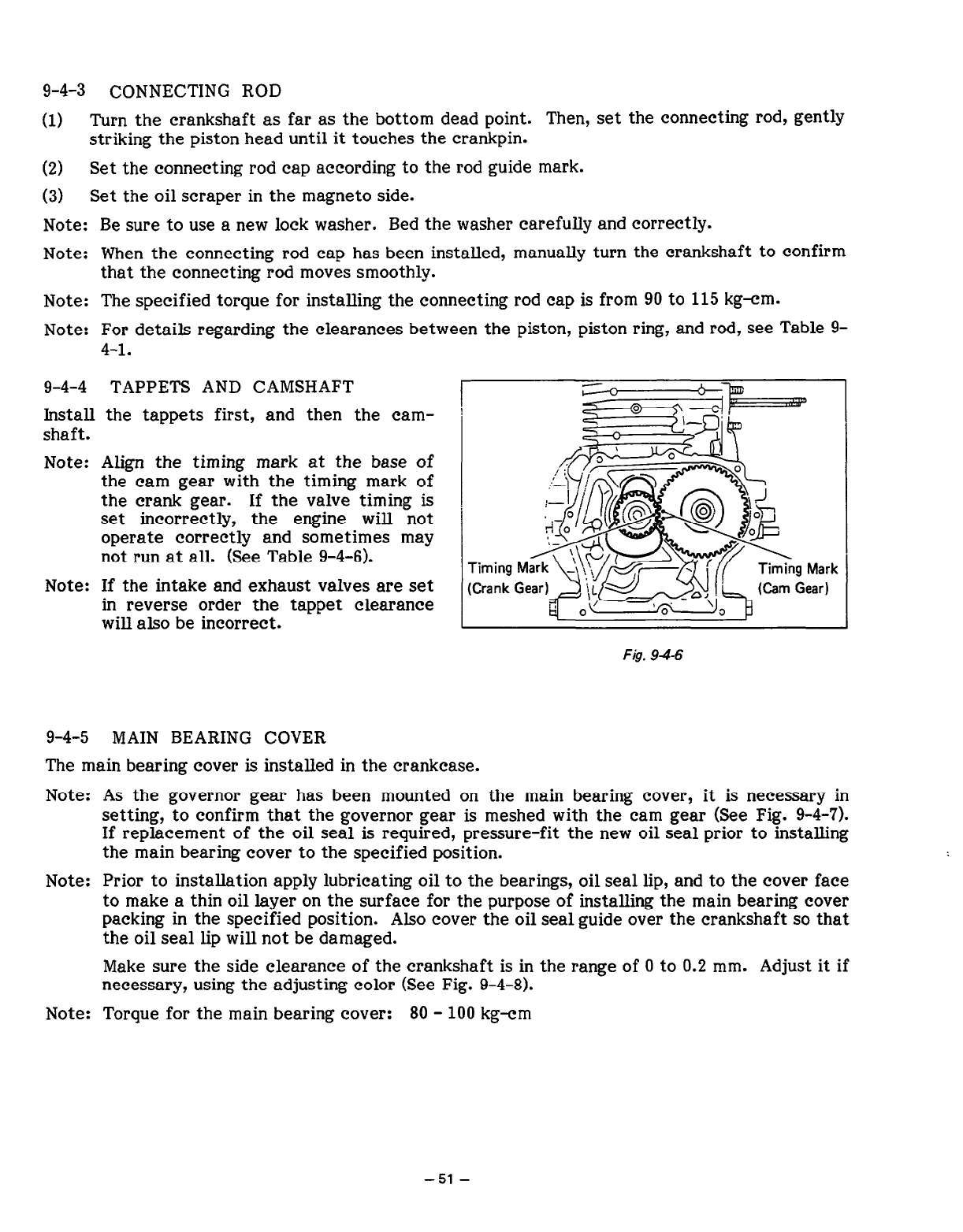
9-4-4 TAPPETS AND CAMSHAFT
Install the tappets first, and then the cam-
shaft.
Note: Align the timing mark at the base of
the cam gear with the timing mark of
the crank gear. If the valve timing is
set incorrectly, the engine will not
operate correctly and sometimes may
not run at all. (See Table 9-4-6).
Note: If the intake and exhaust valves are set
in reverse order the tappet clearance
will also be incorrect.
~g?zq$==
\
{ ,:5g*y
+-J-&[@ f@
Rd q
;:;; :eyr$&p&+&& gm4;;
L
n I
Fig. 94-6
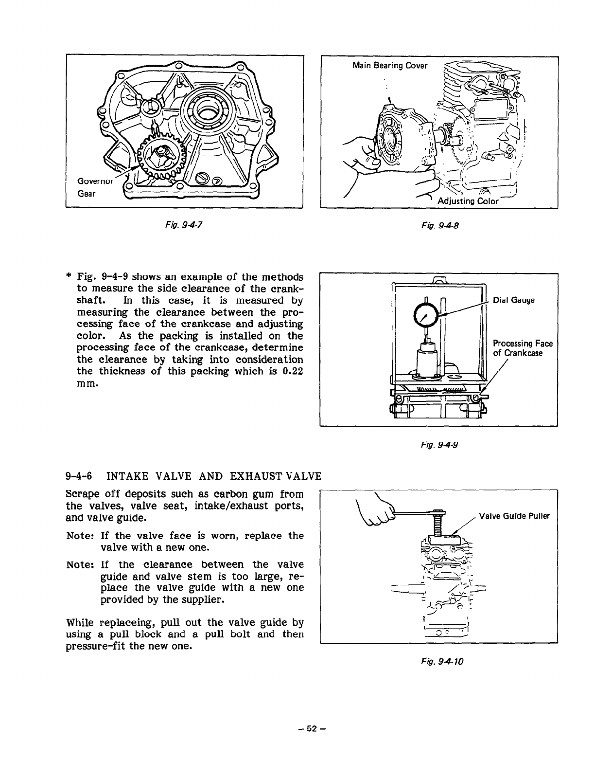
9-4-5 MAIN BEARING COVER
The main bearing cover is installed in the crankcase.
Note: As the governor gear has been mounted on the main bearing cover, it is necessary in
setting, to confirm that the governor gear is meshed with the cam gear (See Fig. 9-4-7).
If replacement of the oil seal is required, pressure-fit the new oil seal prior to installing
the main bearing cover to the specified position.
Note: Prior to installation apply lubricating oil to the bearings, oil seal lip, and to the cover face
to make a thin oil layer on the surface for the purpose of installing the main bearing cover
packing in the specified position. Also cover the oil seal guide over the crankshaft so that
the oil seal lip will not be damaged.
Make sure the side clearance of the crankshaft is in the range of 0 to 0.2 mm. Adjust it if
necessary, using the adjusting color (See Fig. 9-4-8).
Note: Torque for the main bearing cover: 80 - 100 kg-cm
-51-
i
1
Fi$. 94-7 F&. 948
* Fig. 9-4-9 shows an example of the methods
to measure the side clearance of the crank-
shaft. In this case, it is measured by
measuring the clearance between the pro-
cessing face of the crankcase and adjusting
color. As the packing is installed on the
processing face of the crankcase, determine
the clearance by taking into consideration
the thickness of this packing which is 0.22
mm.
!
Main Bearing Cover
I
Dial Gauge
Processing Face
of Crankcase
/
Fig. 9-4-9
9-4-6 INTAKE VALVE AND EXHAUST VALVE
Scrape off deposits such as carbon gum from
the valves, valve seat, intake/exhaust ports,
and valve guide.
Note: If the valve face is worn, replace the
valve with a new one.
Valve Guide Puller
Note: If the clearance between the valve
guide and valve stem is too large, re-
place the valve guide with a new one
provided by the supplier.
While replace@, pull out the valve guide by
using a pull block and a pull bolt and then
pressure-fit the new one.
Fig. 9410
-52-
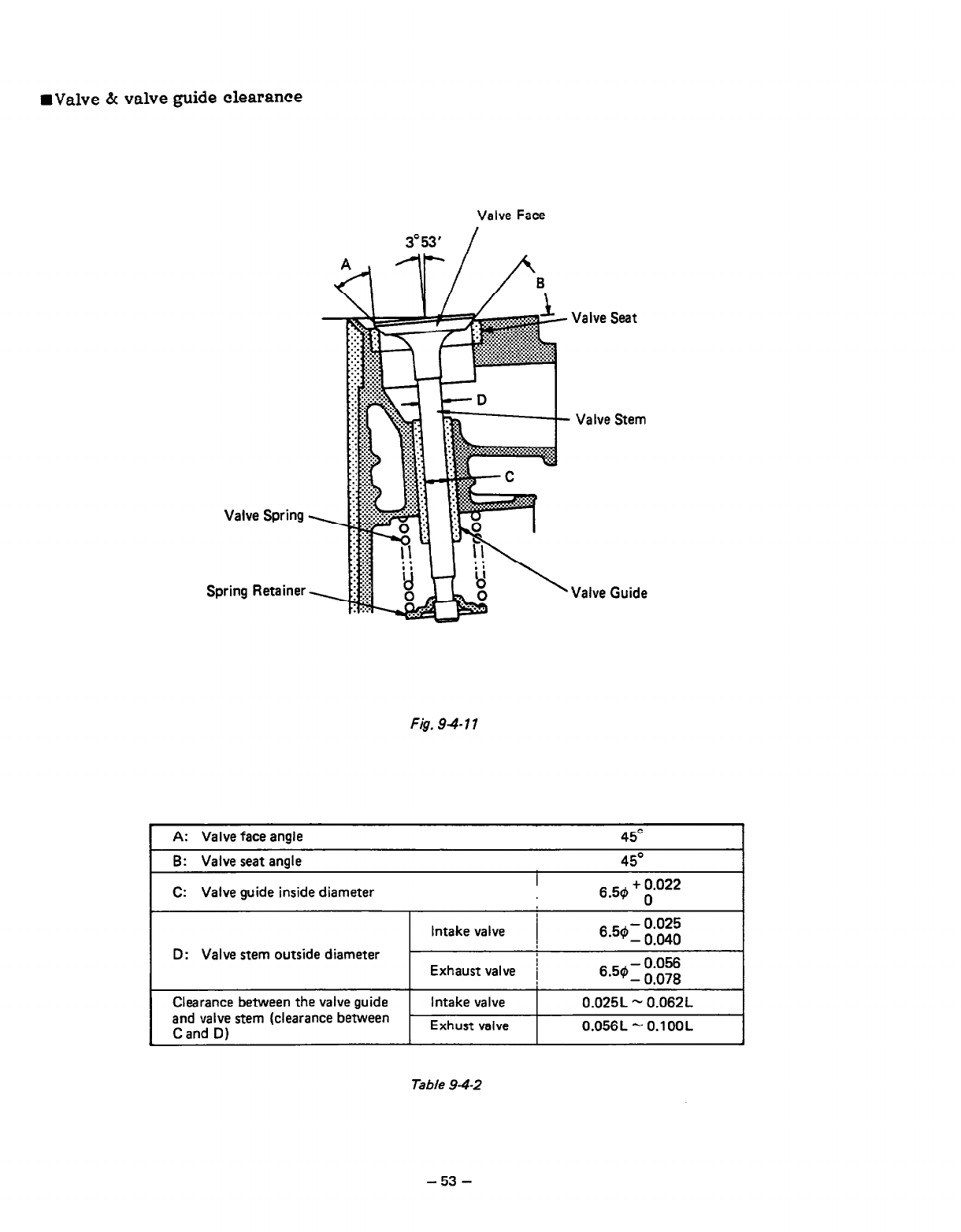
WV&e
h valve guide clearance
Valve Face
3=53' /
Valve Spring
Spring Retainer
Fig. 94 7 1
Valve Seat
Valve Stem
Valve Guide
A: Valve face angle
B: Valve seat angle
I
C: Valve guide inside diameter
D: Valve stem outside diameter
Intake valve 1
6.5$1$;;
Exhaust valve i
-0.056
6*50- 0.078
Clearance between the valve guide Intake valve 0.025L - 0.062L
and valve stem (clearance between -
C and D) Exhust valve 0.056L - O.lOOL ,
Table 9-4-2
-53-
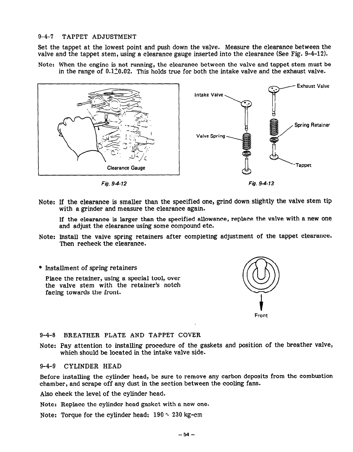
9-4-7 TAPPET ADJUSTMENT
Set the tappet at the lowest point and push down the valve. Measure the clearance between the
valve and the tappet stem, using a clearance gauge inserted into the clearance (See Fig. g-4-12).
Note: When the engine is not running, the clearance between the valve and tappet stem must be
in the range of 0.110.02. This holds true for both the intake valve and the exhaust valve.
e+ig+.
e;
~<Wty!.&<~~
. i’ /:
\ _I ’
.I -Lq
c
p-.
7;: ;:,z<- 1
<y,- ;,: :/ :m
‘2 < j ’ ij>m,Y,,
--A’
C-J. A./,,-, _”
Ii-\ i,
.- J L
Clearance Gauge
Fig. 9-4-12
Intake Valve ‘a r Exhaust Valve
Valve Spring
Fig. 94 13
Note: If the clearance is smaller than the specified one, grind down slightly the valve stem tip
with a grinder and measure the clearance again.
If the clearance is larger than the specified allowance, replace the valve with a new one
and adjust the clearance using some compound etc.
Note: Install the valve spring retainers after completing adjustment of the tappet clearance.
Then recheck the clearance.
* Installment of spring retainers
Place the retainer, using a special tool, over
the valve stem with the retainer’s notch
facing towards the front.
Front
9-4-8 BREATHER PLATE AND TAPPET COVER
Note: Pay attention to installing procedure of the gaskets and position of the breather valve,
which should be located in the intake valve side.
9-4-9 CYLINDER HEAD
Before installing the cylinder head, be sure to remove any carbon deposits from the combustion
chamber, and scrape off any dust in the section between the cooling fans.
Also check the level of the cylinder head.
Note: Replace the cylinder head gasket with a new one.
Note: Torque for the cylinder head: 190 % 230 kg-cm
-54-
9-4-10 IGNITION PLUG
* Torque for the ignition plug: 230 ad 250 kg-cm
(As for a new one (head plug): 120 s 150 kg-cm)
9-4-11 IGNITION COIL, EXCITING COIL, FLYWHEEL AND STARTING PULLEY
(a) Temporarily set the ignition coil and exciting coil in the crankcase and install the flywheel
in the crankshaft. Clamp the starting pulley together with the flywheel.
Note: Installment should be done after wiping away any oil from the crankshaft and taper
section of the flywheel.
Torque for the flywheel: 600 Q 650 kg-cm
(b) Measure air gap between the ignition coil, exciting coil and the flywheel and then clamp
the ignition coil.
The air gap is 0.4 s 0.5 mm.
9-4-l 2 CARBURETOR
In the part of crankcase cylinder, install the gasket, insulator, gasket, carburetor, gasket, control
bracket, and gasket, in this order. Then install the air cleaner body and secure it with two M6
flange nuts. Also lock the air cleaner body with Ml6 x 10 flange bolts.
Torque for the air cleaner clamping: 70 Q 90 kg-cm
Note:Set the control bracket at the position of “RUN”, and then mount it onto the air cleaner.
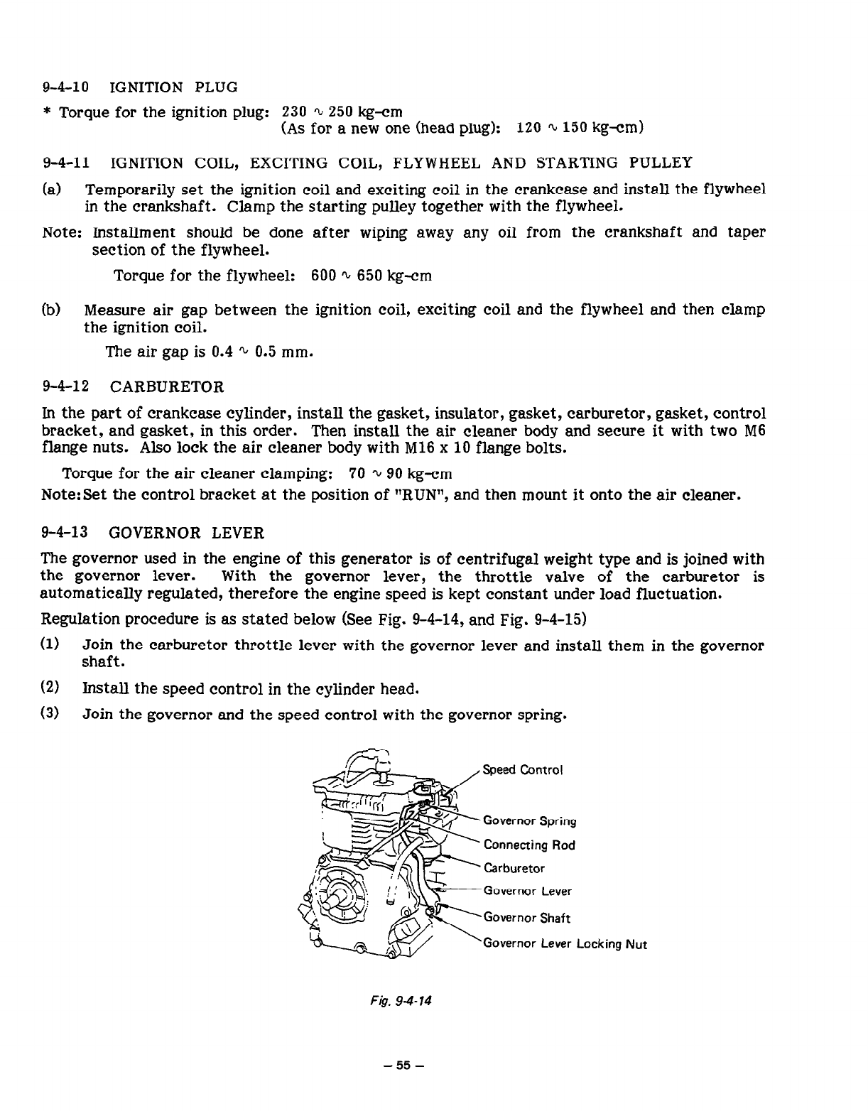
9-4-13 GOVERNOR LEVER
The governor used in the engine
of
this generator is
of
centrifugal weight type and is joined with
the governor lever. With the governor lever, the throttle valve
of
the carburetor is
automatically regulated, therefore the engine speed is kept constant under load fluctuation.
Regulation procedure is as stated below (See Fig. 9-4-14, and Fig. 9-4-15)
(1) Join the carburetor throttle lever with the governor lever and install them in the governor
shaft.
(2) Install the speed control in the cylinder head.
(3) Join the governor and the speed control with the governor spring.
,
a@==-
,,
//
SE+
yl I Ir;; L
- /-!
!zsc-
@
2s
j&f
-&
cc=+
$T, +,
&
\.T< I’
G
‘L--
Governor Lever
Governor Lever Locking Nut
F&. 9-4-14
-55-
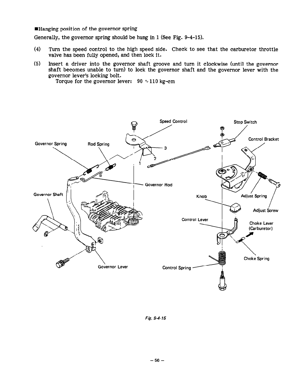
WHanging position of the governor spring
Generally, the governor spring should be hung in 1 (See Fig. 9-4-15).
(4) Turn the speed control to the high speed side. Check to see that the carburetor throttle
valve has been fully opened, and then lock it.
(5) Insert a driver into the governor shaft groove and turn it clockwise (until the governor
shaft becomes unable to turn) to lock the governor shaft and the governor lever with the
governor lever’s locking bolt.
Torque for the governor lever: 90 Q 110 kg-cm
Speed Control Stop Switch
Governor Shaft
Choke Lever
Governor Lever
Choke Spring
F@. 9-b 15
- 56 -
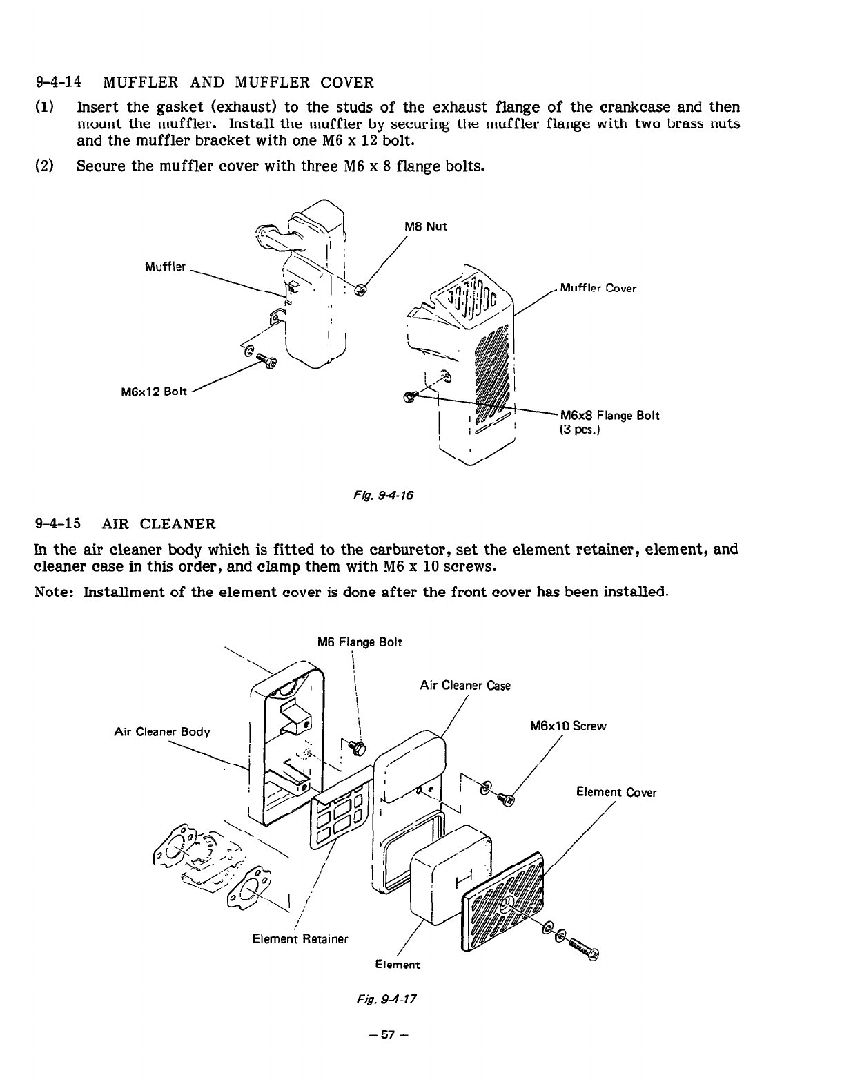
9-4-14 MUFFLER AND MUFFLER COVER
(1) Insert the gasket (exhaust) to the studs of the exhaust flange of the crankcase and then
mount the muffler. Install the muffler
by
securing the muffler flange with two brass nuts
and the muffler bracket with one M6 x 12 bolt.
(2) Secure the muffler cover with three M6 x 8 flange bolts.
Muffler <??g?g;/M8 Nut
. , ’
Muffler Cover
M6x8 Flange Bolt
(3 PCs.1
F&. 9-4-16
9-4-15 AIR CLEANER
In the air cleaner body which is fitted to the carburetor, set the element retainer, element, and
cleaner case in this order, and clamp them with M6 x 10 screws.
Note: Installment of the element cover is done after the front cover has been installed.
M6 Flange Bolt
Air Cleaner Case
Element
Fig. 94-17
-57-
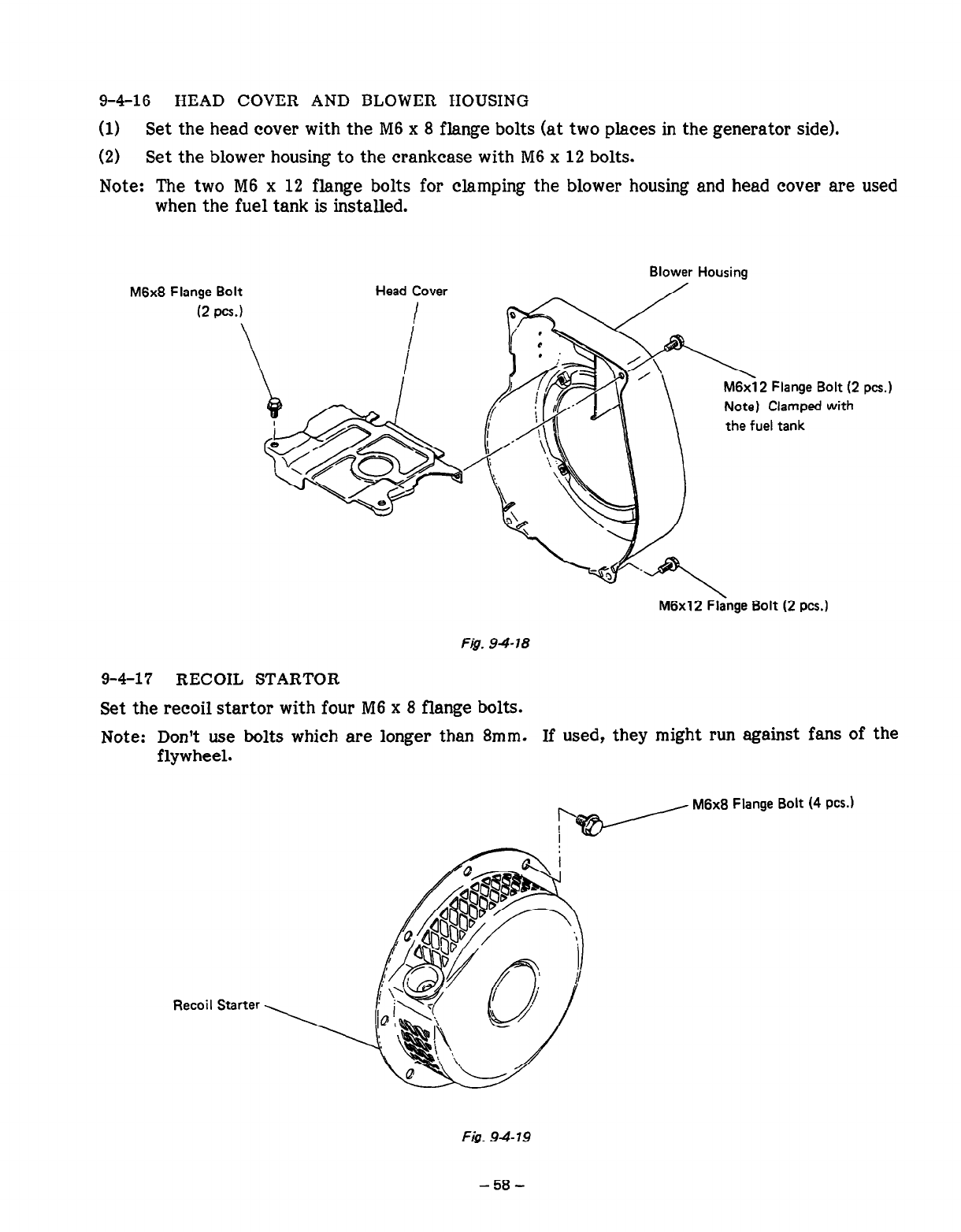
9-4-16 HEAD COVER AND BLOWER HOUSING
(1) Set the head cover with the M6 x 8 flange bolts (at two places in the generator side).
(2) Set the blower housing to the crankcase with M6 x 12 bolts.
Note: The two M6 x 12 flange bolts for clamping the blower housing and head cover are used
when the fuel tank is installed.
Blower Housing
M6x8 Flange Bolt Head Cover
(2
PCs.1 I
2 Flange Bolt (2
Clamped with
the fuel tank
PCs.1
M6x12 Flange Bolt (2
PCS.)
Fjg. 94-78
9-4-1’7 RECOIL STARTOR
Set the recoil startor with four M6 x 8 flange bolts.
Note: Don’t use bolts which are longer than 8mm. If used, they might run against fans of the
flywheel.
v
M6x8 Flange Bolt (4
PCS.)
Recoil Starter
Fig. 94 79
- 58 -
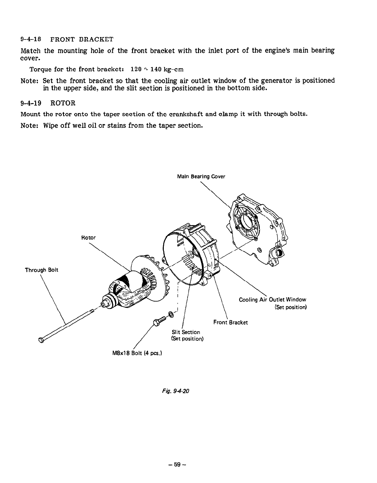
9-4-18 FRONT BRACKET
Match the mounting hole of the front bracket with the inlet port of the engine’s main bearing
cover.
Torque for the front bracket: 120 0u 140 kg-cm
Note: Set the front bracket so that the cooling air outlet window
of
the generator is positioned
in the upper side, and the slit section is positioned in the bottom side.
9-4-l 9 ROTOR
Mount the rotor onto the taper section of the crankshaft and clamp it with through bolts.
Note: Wipe off well oil or stains from the taper section.
Main Bearing Cover
Rotor
Through Bolt
Outlet Window
(Set position)
Slit Section
M8x18 Bolt (4 PCS.)
Fig. 9420
- 59 -
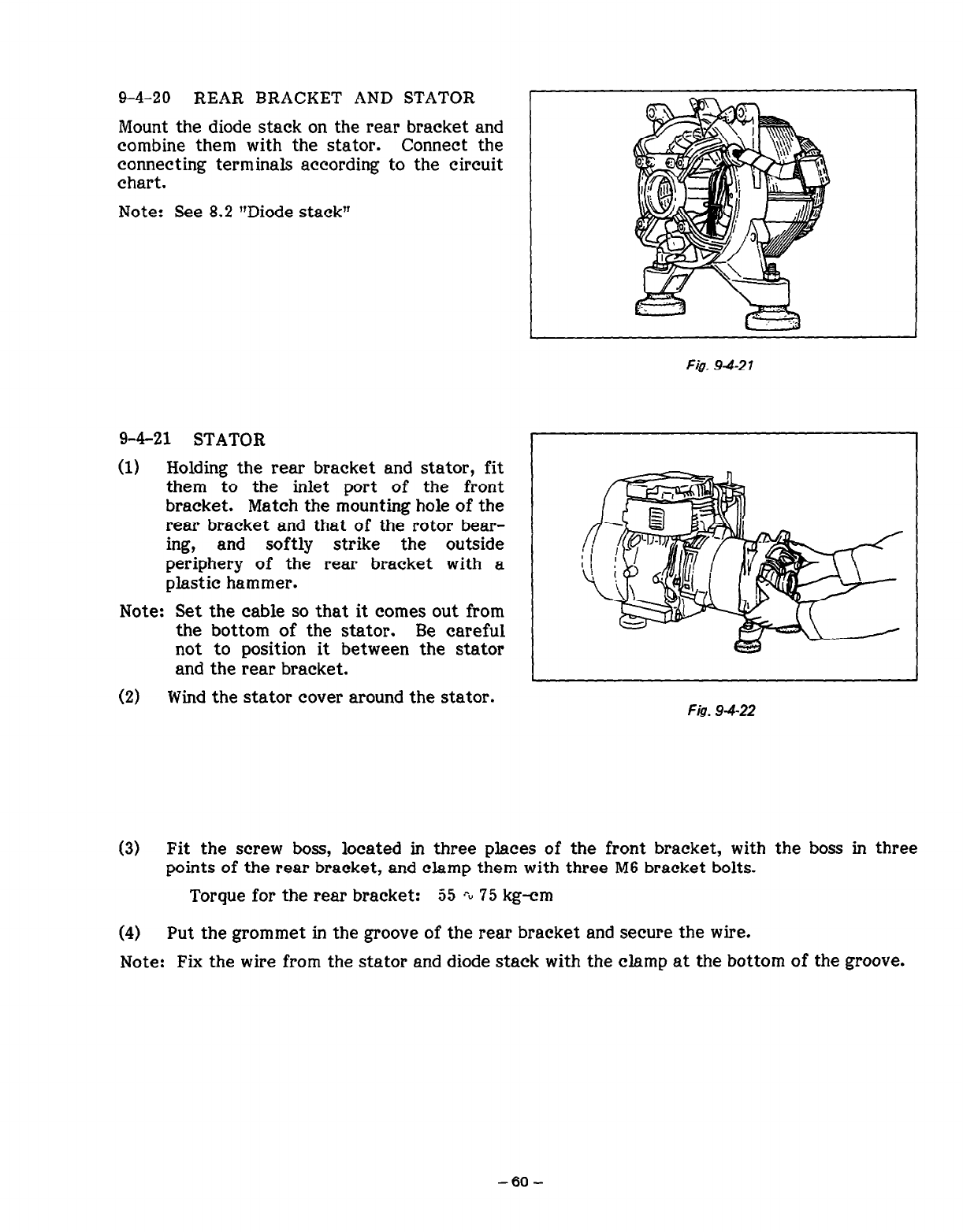
9-4-20 REAR BRACKET AND STATOR
Mount the diode stack on the rear bracket and
combine them with the stator. Connect the
connecting terminals according to the circuit
chart.
Note: See 8.2 “Diode stack”
9-4-21 STATOR
(1) Holding the rear bracket and stator, fit
them to the inlet port of the front
bracket. Match the mounting hole of the
rear bracket and that of the rotor bear-
ing, and softly strike the outside
periphery of the rear bracket with a
plastic hammer.
Note: Set the cable so that it comes out from
the bottom of the stator. Be careful
not to position it between the stator
and the rear bracket.
Fig. 94-27
(2) Wind th e s a t t or cover around the stator. Fig. 9-4-22
(3) Fit the screw boss, located in three places of the front bracket, with the boss in three
points of the rear bracket, and clamp them with three M6 bracket bolts.
Torque for the rear bracket: 55 .^u 75 kg-cm
(4) Put the grommet in the groove of the rear bracket and secure the wire.
Note: Fix the wire from the stator and diode stack with the clamp at the bottom of the groove.
-6O-
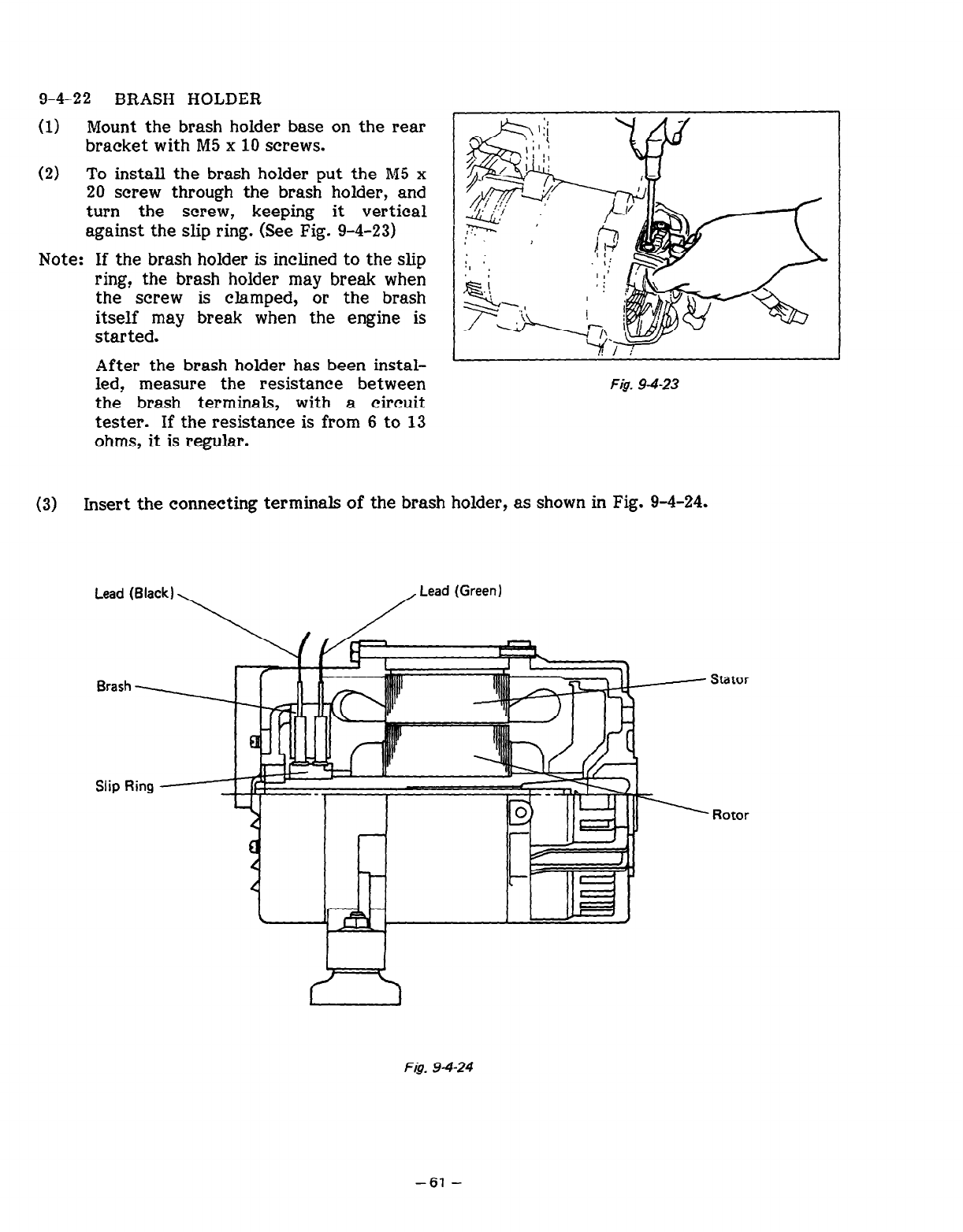
9-4-22 BRASH HOLDER
(1) Mount the brash holder base on the rear
bracket with PI5 x 10 screws.
(2) To install the brash holder put the M5 x
20 screw through the brash holder, and
turn the screw, keeping it vertical
against the slip ring. (See Fig. 9-4-23)
Note: If the brash holder is inclined to the slip
ring? the brash holder may break when
the screw is clamped, or the brash
itself may break when the engine is
started.
After the brash holder has been instal-
led? measure the resistance between
the brash terminals, with a circuit
tester. If the resistance is from 6 to 13
ohms, it is regular.
I
Fig. 94-23
(3) Insert the connecting terminals of the brash holder, as shown in Fig. 9-4-24.
Lead (Black)
\ /
Lead (Green)
Stator
Rotor
Fig. 94-24
-61-
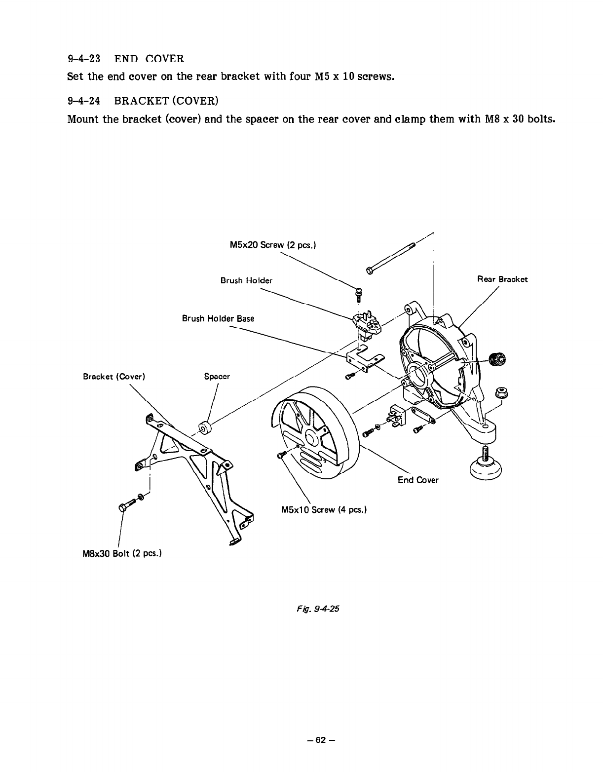
9-4-23 END COVER
Set the end cover on the rear bracket with four M5 x 10 screws.
9-4-24 BRACKET (COVER)
Mount the bracket (cover) and the spacer on the rear cover and clamp them with MS x 30 bolts.
M5x20 Screw (2 PCS.) /$a/”
Brush Holder Rear Bracket
Bracket
Brush Holde\y , ,
\
p h Cover
M5xlO Screw (4 PCS.)
I
d
M8x30 iiolt (2 PCS.)
Ft& 9425
-62-
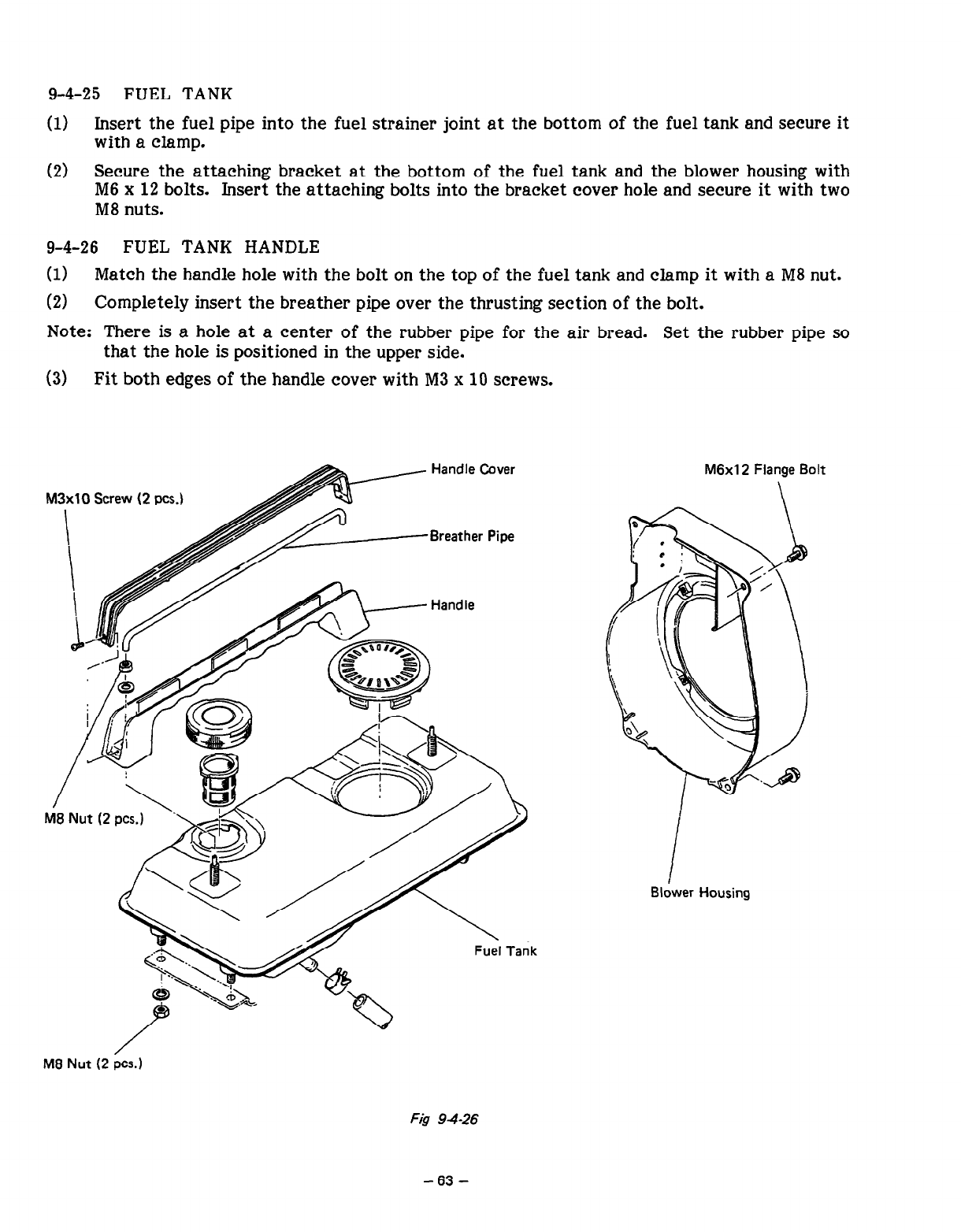
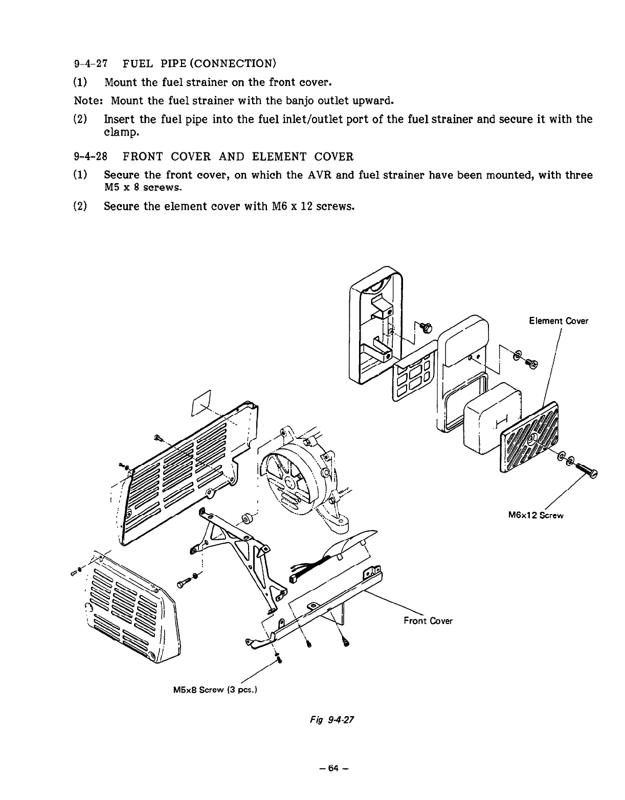
9-4-27 FUEL PIPE (CONNECTION)
(1) Mount the fuel strainer on the front cover.
Note: Mount the fuel strainer with the banjo outlet upward.
(2) Insert the fuel pipe into the fuel inlet/outlet port of the fuel strainer and secure it with the
clamp.
9-4-28 FRONT COVER AND ELEMENT COVER
(1) Secure the front cover, on which the AVR and fuel strainer have been mounted, with three
M5 x 8 screws.
(2) Secure the element cover with M6 x 12 screws.
Element Cover
/
M6x12 Screw
Front Cover
M5x8 Screw (3 PCS.)
FQ 94-27
-64 -
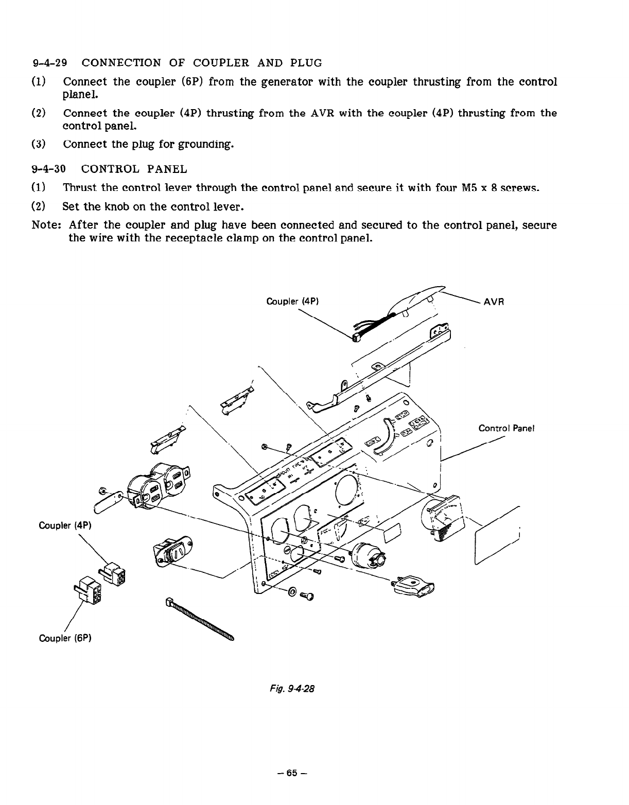
9-4-29 CONNECTION OF COUPLER AND PLUG
(1) Connect th e coupler (6P) from the generator with the coupler thrusting from the control
planel.
(2) Connect the coupler (4P) thrusting from the AVR with the coupler (4P) thrusting from the
control panel.
(3) Connect the plug for grounding.
9-4-30 CONTROL PANEL
(1) Thrust the control lever through the control panel and secure it with four M5 x 8 screws.
(2) Set the knob on the control lever.
Note: After the coupler and plug have been connected and secured to the control panel, secure
the wire with the receptacle clamp on the control panel.
Fig. 94-28
-65-
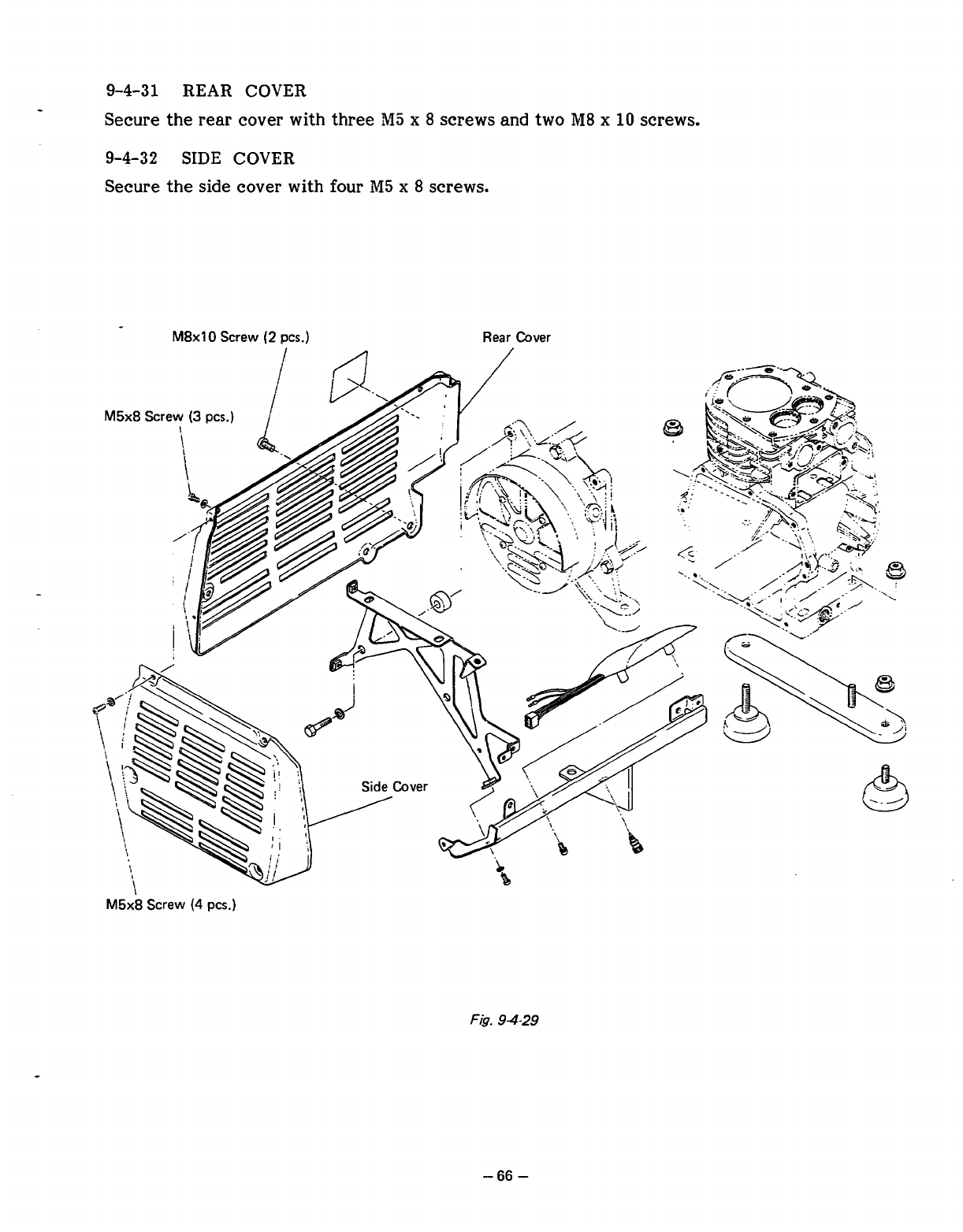
9-4-31
REAR COVER
-
Secure the rear cover
with
three
"I
x
8
screws and two
&I8
x
10
screws.
9-4-32
SIDE COVER
Secure the
side
cover with
four
M5
x
8
screws.
M8x10
Screw
(2
pcs.)
Rear Cover
F&.
94-29
-66
-
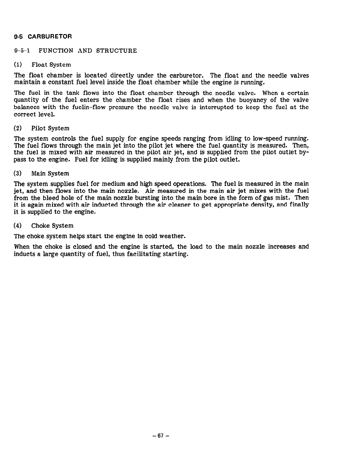
9-5 CARBURETOR
9-5-l FUNCTION AND STRUCTURE
(1) Float System
The float chamber is located directly under the carburetor. The float and the needle valves
maintain a constant fuel level inside the float chamber while the engine is running.
The fuel in the tank flows into the float chamber through the needle valve. When a certain
quantity of the fuel enters the chamber the float rises and when the buoyancy of the valve
balances with the fuelin-flow pressure the needle valve is interrupted to keep the fuel at the
correct level.
(2) Pilot System
The system controls the fuel supply for engine speeds ranging from idling to low-speed running.
The fuel flows through the main jet into the pilot jet where the fuel quantity is measured. Then,
the fuel is mixed with air measured in the pilot air jet, and is supplied from the pilot outlet by-
pass to the engine. Fuel for idling is supplied mainly from the pilot outlet.
(3) Main System
The system supplies fuel for medium and high speed operations. The fuel is measured in the main
jet, and then flows into the main nozzle. Air measured in the main air jet mixes with the fuel
from the bleed hole of the main nozzle bursting into the main bore in the form of gas mist. Then
it is again mixed with air inducted through the air cleaner to get appropriate density, and finally
it is supplied to the engine.
(4) Choke System
The choke system helps start the engine in cold weather.
When the choke is closed and the engine is started, the load to the main nozzle increases and
inducts a large quantity of fuel, thus facilitating starting.
-67
-
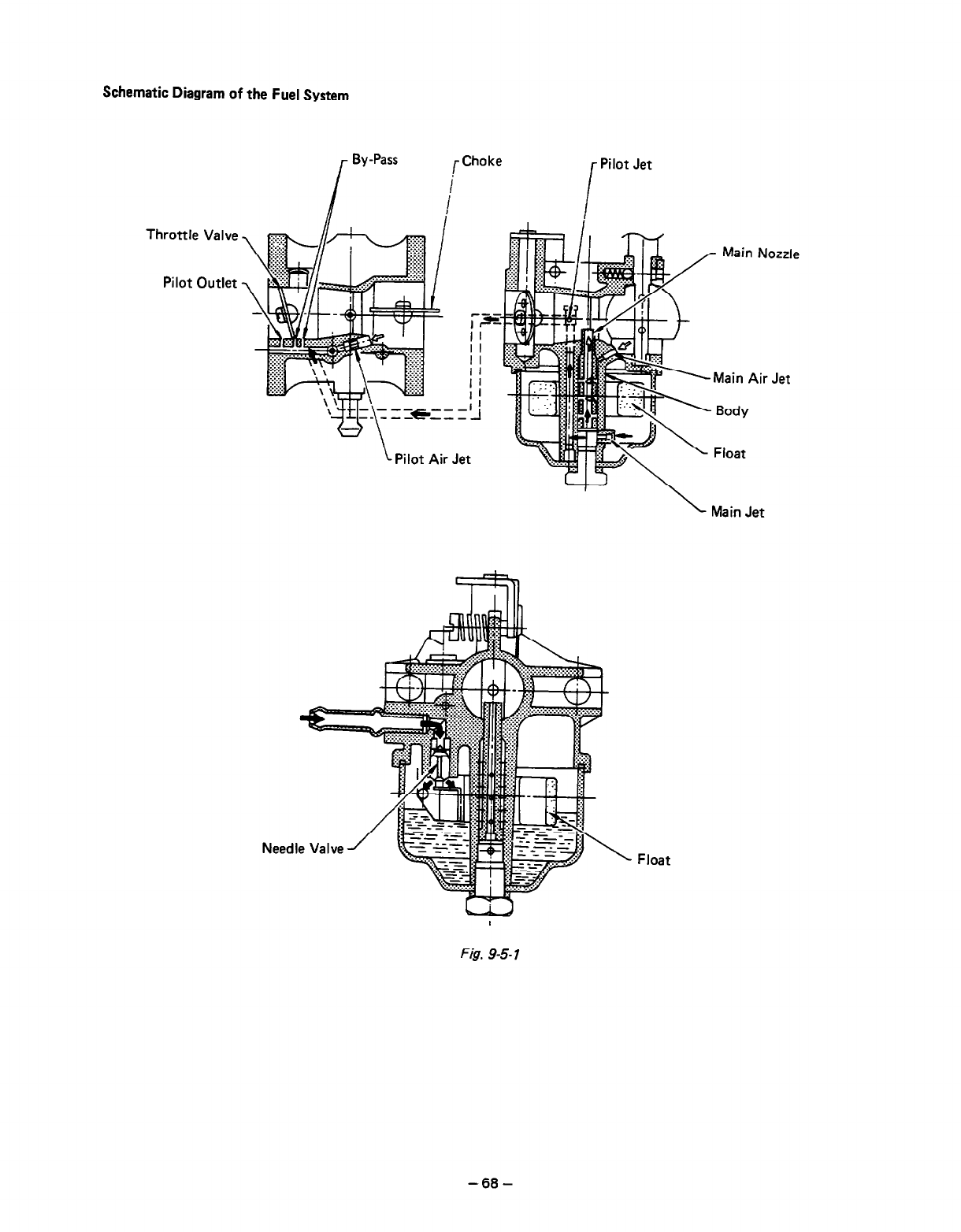
Schematic Diagram of the Fuel System
r
By-Pass
Throttle Valve
Pilot Outlet
r
Choke Pilot Jet
i
Jet
Main Nozzle
\
Main Jet
Float
Fig. 9-5-l
-68-
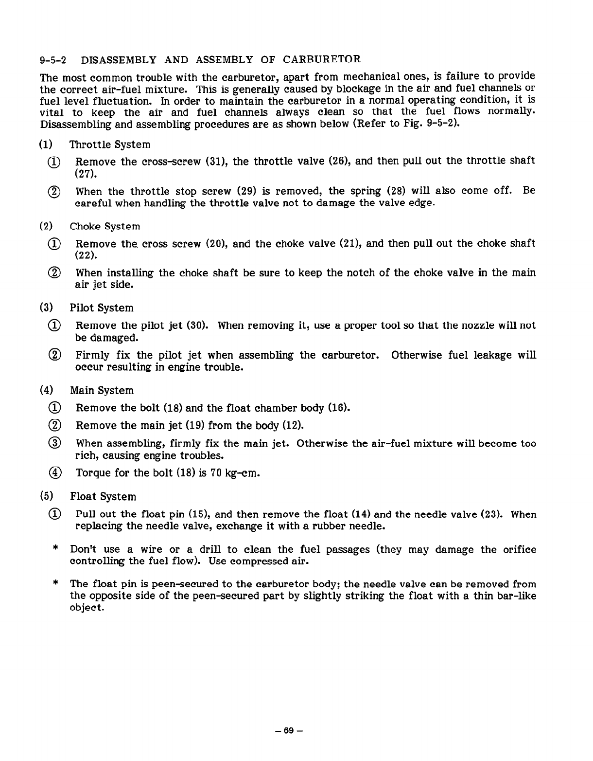
9-5-2 DISASSEMBLY AND ASSEMBLY OF CARBURETOR
The most common trouble with the carburetor, apart from mechanical ones, is failure to provide
the correct air-fuel mixture. This is generally caused by blockage in the air and fuel channels or
fuel level fluctuation. In order to maintain the carburetor in a normal operating condition, it is
vital to keep the air and fuel channels always clean so that the fuel flows normally.
Disassembling and assembling procedures are as shown below (Refer to Fig. 9-5-2).
(1) Throttle System
@ Remove the cross-screw (31), the throttle valve (26), and then pull out the throttle shaft
(27).
0 When the throttle stop screw (29) is removed, the spring (28) will also come off. Be
careful when handling the throttle valve not to damage the valve edge.
(2) Choke System
@) Remove the. cross screw (20), and the choke valve (21), and then pull out the choke shaft
(22).
@ When installing the choke shaft be sure to keep the notch of the choke valve in the main
air jet side.
(3) Pilot System
@ Remove the pilot jet (30). When removing it, use a proper tool so that the nozzle will not
be damaged.
@ Firmly fix the pilot jet when assembling the carburetor. Otherwise fuel leakage will
occur resulting in engine trouble.
(4) Main System
@ Remove the bolt (18) and the float chamber body (16).
@ Remove the main jet (19) from the body (12).
@ When assembling, firmly fix the main jet. Otherwise the air-fuel mixture will become too
rich, causing engine troubles.
@ Torque for the bolt (18) is 70 kg-cm.
(5) Float System
@ Pull out the float pin (15), and then remove the float (14) and the needle valve (23). When
replacing the needle valve, exchange it with a rubber needle.
* Don’t use a wire or a drill to clean the fuel passages (they may damage the orifice
controlling the fuel flow). Use compressed air.
* The float pin is peensecured to the carburetor body; the needle valve can be removed from
the opposite side of the peen-secured part by slightly striking the float with a thin bar-like
object.
-69-
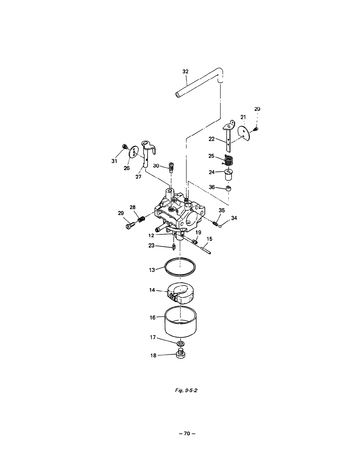
3i
I
20
25
184
Fig. 9-5-2
- 70 -
10. SAFETY PRECAUTIONS
10-l FIRE PREVENTION
(1) Keep the generator away from combustible materials during operations, or ground the
generator by making use of its grounding terminal. Take special precautions towards
flammable substances.
(2) Do not run the generator in an inclined position. Avoid moving the generator while it is
running. Otherwise, there is a risk of the generator falling or fuel leakage.
(3) If the generator is enclosed or covered by an object while running, cooling efficiency will
become lower, which may result in over-heating of the generator.
(4) Keep the generator at least 1 m away from a building.
(5) Be sure to stop the engine before filling the fuel tank. If the fuel is filled while the engine
is running, fuel vapor from the fuel tank or spilt fuel may be ignited, thus causing a fire.
(6) Fuel u se d in an engine is very volatile and flammable. Take special precautions not to spill
the fuel when filling the fuel tank. If the fuel is spilt, wipe it off thoroughly and let it dry
before restarting the engine.
(7) Be sure to fill the fuel only up to the level specified at the fuel supply port.
(8) When filling the fuel tank, be careful not to smoke or use an open flame.
10-2 PRECAUTIONS FOR EXHAUST GASES
(1) Don’t use the generator in poorly ventilated places such as an office, warehouse, narrow
tunnel, well, hold, or tank etc. If the generator is used in such places as mentioned above,
the operator may suffer carbon monoxide poisoning.
(2) Always direct the exhaust port toward the well ventilated open space.
103 OTHER PRECAUTIONS
(1) To prevent electric shock, don’t handle the generator with wet hands. When the generator
is used to drive a submersible pump or other similar equipment, be sure to connect the
earth cord of the generator to the earth cable of the pump.
(2) Don’t splash water over the generator and avoid using the generator in the rain. If the
generator gets wet, it may fail to start smoothly and the operator may possibly receive
severe electric shock.
(3) Never connect the generator to the existing indoor cable. If connected, the generator will
burn out.
(4) Don’t use the generator with its cover removed as the operator may be injured or receive
electric shock.
- 71 -
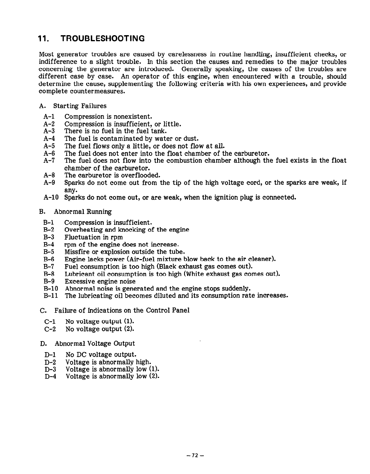
11. TROUBLESHOOTING
Most generator troubles are caused by carelessness in routine handling, insufficient checks, or
indifference to a slight trouble. Jn this section the causes and remedies to the major troubles
concerning the generator are introduced. Generally speaking, the causes of the troubles are
different case by case. An operator of this engine, when encountered with a trouble, should
determine the cause, supplementing the following criteria with his own experiences, and provide
complete countermeasures.
Compression is nonexistent.
A. Starting Failures
A-l
A-2
A-3
A-4
A-5
A-6
A-7
Compression is insufficient, or little.
There is no fuel in the fuel tank.
The fuel is contaminated by water or dust.
The fuel flows only a little, or does not flow at all.
The fuel does not enter into the float chamber of the carburetor.
The fuel does not flow into the combustion chamber although the fuel exists in the float
chamber of the carburetor.
A-8
A-9 The carburetor is overflooded.
Sparks do not come out from the tip of the high voltage cord, or the sparks are weak, if
any.
A-10 Sparks do not come out, or are weak, when the ignition plug is connected.
B. Abnormal Running
B-l
B-2
B-3
B-4
B-5
B-6
B-7
B-8
B-9
B-10
B-l 1
Compression is insufficient.
Overheating and knocking of the engine
Fluctuation in rpm
rpm of the engine does not increase.
Missfire or explosion outside the tube.
Engine lacks power (Air-fuel mixture blow back to the air cleaner).
Fuel consumption is too high (Black exhaust gas comes out).
Lubricant oil consumption is too high (White exhaust gas comes out).
Excessive engine noise
Abnormal noise is generated and the engine stops suddenly.
The lubricating oil becomes diluted and its consumption rate increases.
C. Failure of Indications on the Control Panel
C-l No voltage output (1).
C-2 No voltage output (2).
D. Abnormal Voltage Output
D-l No DC voltage output.
D-2 Voltage is abnormally high.
D-3 Voltage is abnormally low (1).
D-4 Voltage is abnormally low (2).
-72-
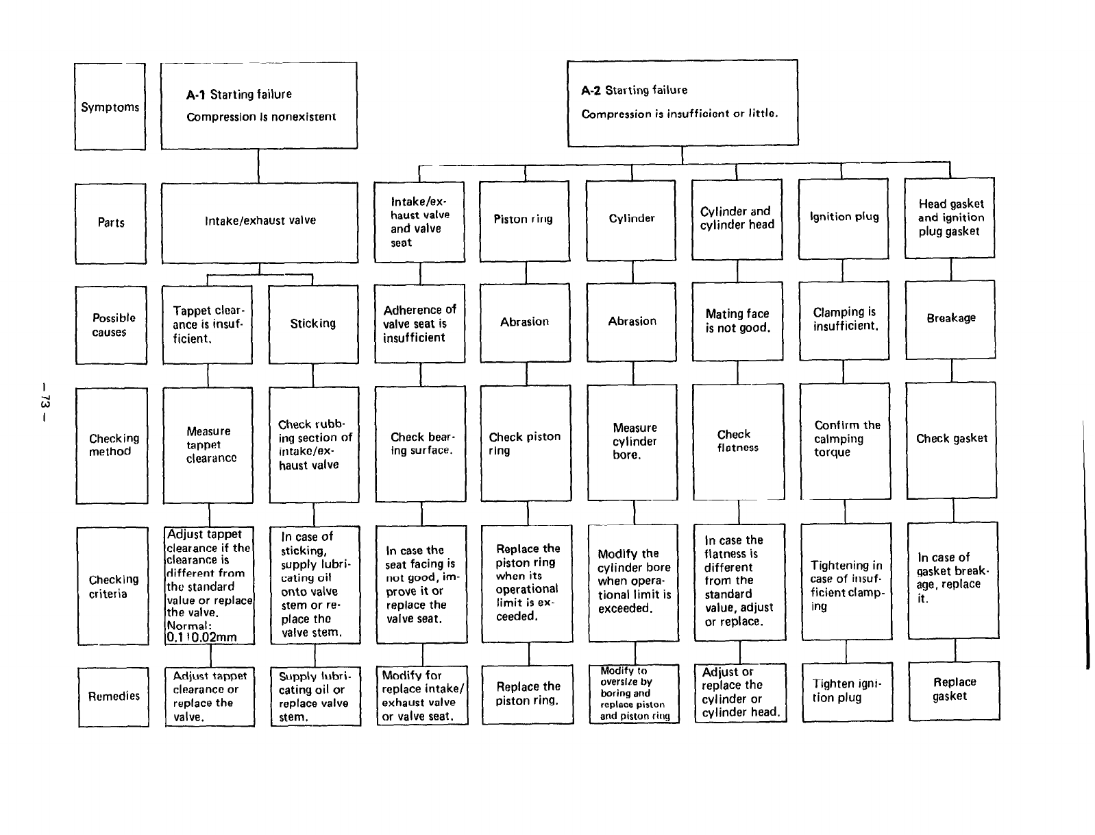
II
Symptoms
1
Parts
-
A-l
Starting failure
Compression is nonexistent
Intake/exhaust valve
[ A-2 Starting failur;
Compression is insufficient or little
,
Adjust tappet
clearance if the
1
clearance is
different from
the standard
value or replace
I
In case of
sticking,
supply lubri-
cating oil
onto value
stem or re-
place the
valve stem.
Replace the
piston ring
when its
operational
limit is ex-
ceeded.
Modify the
cylinder bore
when opera-
tional limit is
exceeded.
Tightening in
case of insuf-
ficient clamp-
ing
In case of
gasket break-
age, replace
it.
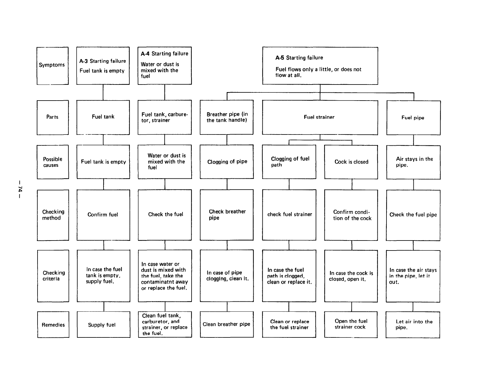
.-.
n
Symptoms
A-3
Starting failure
I
Fuel tank is empty
A-4
Starting failure
I
Water or dust is
mixed with the
fuel
]
Fuel flows only a little, or does not
Breather pipe (in
the tank handle)
Clogging of pipe
Fuel tank, carbure-
Fuel tank is empty Cock is closed
Water or dust is
mixed with the Air stays in the
-7
Check the fuel
I
Check breather
pipe check fuel strainer Check the fuel pipe
-J
Confirm condi-
tion of the cock
Checking
method
Checking
criteria
Confirm fuel
In case the fuel
tank is empty,
supply fuel.
In case of pipe
clogging, clean it.
In case the fuel
path is clogged,
clean or replace it.
In case water or
dust is mixed with
the fuel, take the
contaminatnt away
or replace the fuel.
In case the air stays
in the pipe, let it
In case the cock is
closed, open it.
out.
Let air into the
strainer cock
El
Remedies
r-
1
Clean or replace
the fuel strainer
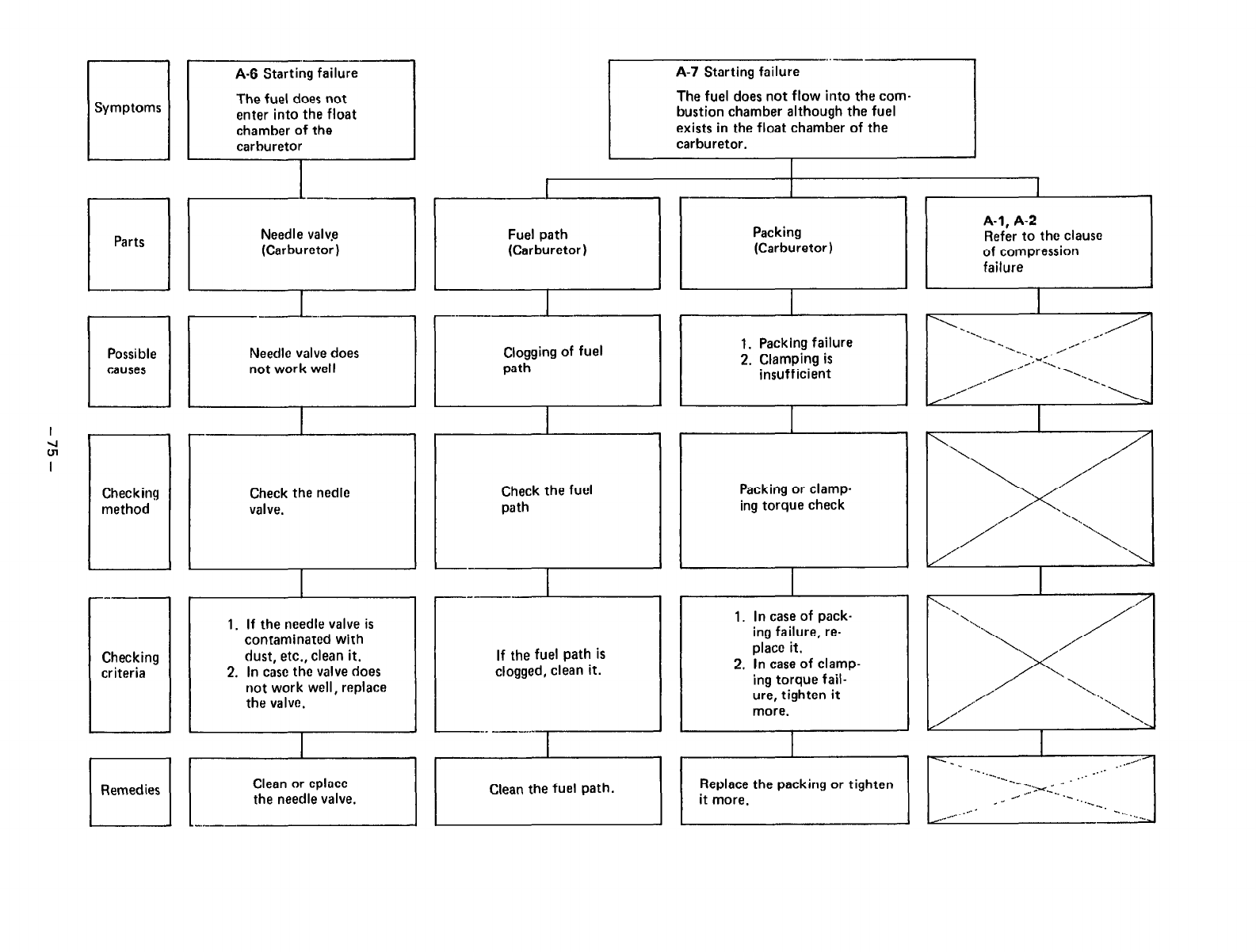
q -
.--
A-6 Starting failure
Symptoms The fuel does not
enter into the float
chamber of the
carburetor
The fuel does not flow into the com-
bustion chamber although the fuel
exists in the float chamber of the
I r
Fuel path
(Carburetor) Packing
(Carburetor)
-- I
Packing or clamp-
- ,
ing torque check
----
Checking
criteria
1. If the needle valve is
contaminated with
dust, etc., clean it.
2. In cast the valve does
not work well, replace
the valve.
If the fuel path is
clogged, clean it.
-“. -------I
I
‘\. ‘*-X.
‘...,
“L.., ,A’ /“”
,,,- 1.
-1..
,,,/ , .“*. A\,+,,
/iiimlLIIl ry-$j-q pzlzq Fr1 Ilr~
Replace the packiny or tighten
I
1. In case of pack-
ing failure, re-
place it.
2. In case of clamp-
ing torque fail-
ure, tighten it
more.
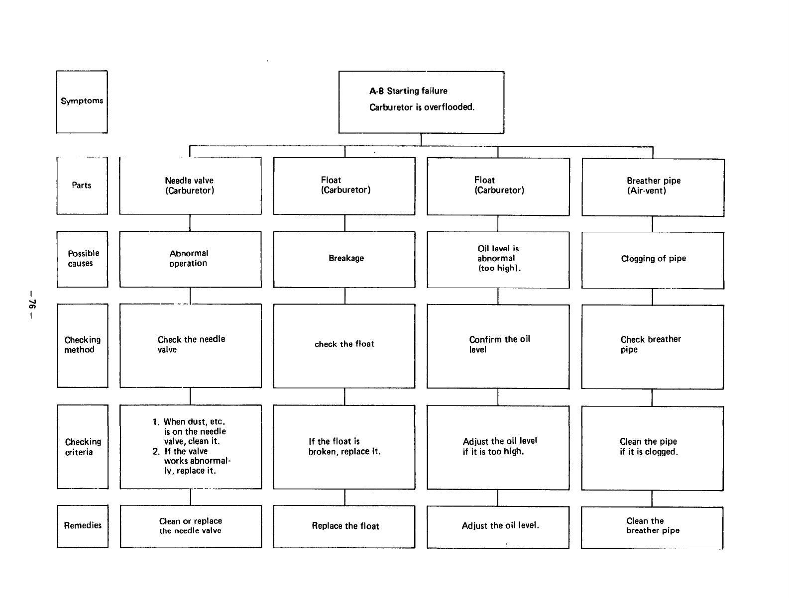
q
Symptoms
q
Parts
----
-
Needle valve
(Carburetor) Float
(Carburetor)
--.--
I
Float Breather pipe
(Carburetor) (Air-vent)
1 _~
q
Possible
causes Abnormal
operation Breakage Oil level is
abnormal
(too high).
I
Clogging of pipe
Checking
method
Checking
criteria
J
Check the needle
valve
I - -.-.I
I
1. When dust, etc.
is on the needle
valve, clean it.
2. If the valve
works abnormal-
ly, replace it.
T
_- _.. ..__-
If the float is
broken, replace it. Adjust the oil level
if it is too high.
I
r-----l1Ill I
check the float Confirm the oil
level
1 Remedies / 1 ~~,ne$,ree$~~ Adjust theoil level.
1 1 Replace the float I 1
Check breather
pipe
Clean the pipe
if it is clogged.
Clean the
breather pipe
I I
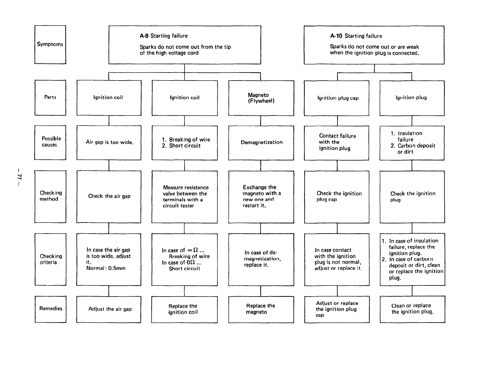
II
Symptoms
A-9 Starting failure
Sparks do not come out from the tip
of the high voltage cord
A-10
Starting failure
Sparks do not come out or are weak
when the ignition plug is connected.
a
Ignition coil
L
Magneto
(Flywheel)
il
Ignition coil plug cap
Contact failure
with the
ignition plug
Ignition plug
1. Insulation
failure
2. Carbon deposit
or dirt
E
Demagnetization
a
Air gap is too wide. 1. Breaking of wire
2. Short circuit
I
=I
I
Check the air gap
Measure resistance
valve between the
terminals with a
circuit tester
I
the ignition
Check
plug
Exchange the
magneto with a
new one and
restart it.
Checking
met hod
--
Check the ignition
Plug cap
In case contact
with the ignition
plug is not normal,
adjust or replace it.
I
I
-.
Checking
I
criteria
-
1. In case of insulation
failure, replace the
ignition plug.
2. In case of carborn
deposit or dirt, clean
or replace the ignition
plug.
In case the air gap
is too wide, adjust
it.
Normal : 0.5mm
In case of -S2 . . .
Breaking of wire
in case of OS1 . . .
Short circuit
In case of de-
magnetization,
replace it.
0
Remedies Adjust the air gap
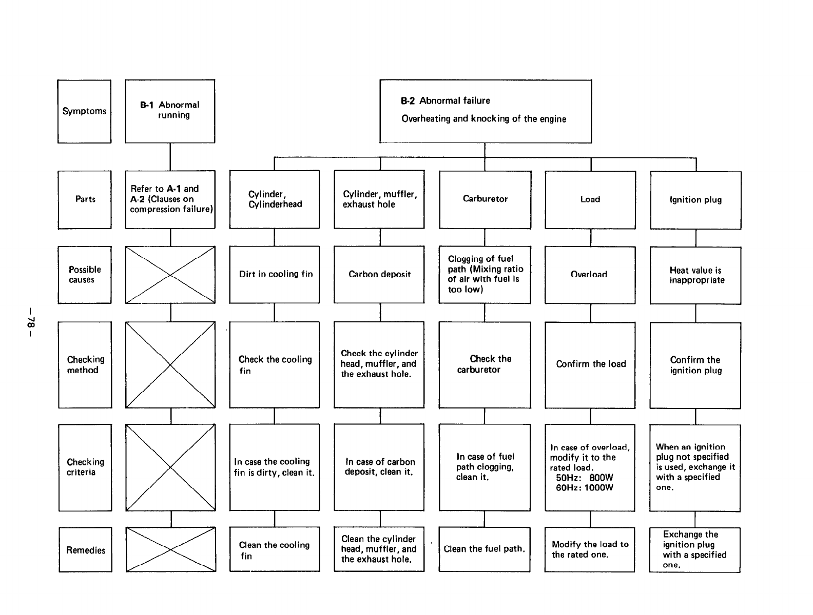
q
Symptoms B-2 Abnormal failure
Overheating and knocking of the engine
B-l
Abnormal
running
Refer to
A-l
and
A-2 (Clauses on
compression failure)
Cylinder, muffler, Carburetor
0
I
Load
Overload
Ignition plug
c
_.
r?J
/’ \
Heat value is
El
inappropriate
Clogging of fuel
path (Mixing ratio
of air with fuel is
too low)
I
2
I
I
Check the cooling
fin
Check the cylinder
head, muffler, and
the exhaust hole.
Check the
carburetor
I--
Confirm the load
Checking
method Confirm the
ignition plug
In case of fuel
path clogging,
clean it.
In case of carbon
deposit, clean it.
When an ignition
plug not specified
is used, exchange it
with a specified
one.
In case of overload,
modify it to the
rated load.
50Hz: 8OOW
60Hz: looow
In case the cooling
fin is dirty, clean it.
Checking
criteria
I
l-l
Remedies ICleanthefuelpath.)
Clean the cylinder
head, muffler, and
the exhaust hole,
Clean the cooling
fin
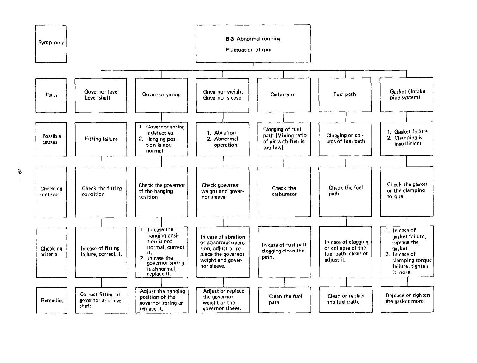
El
Symptoms B-3 Abnormal running
Fluctuation of rpm
rl
Remedies
In case of fitting
failure, correct it.
I
Correct fitting of
governor and level
shaft
hanging posi-
tion is not
normal. correct
it.
2. In case the
governor spring
Is abnormal,
replace it.
Adjust the hanging
position of the
governor spring or
In case of abration
or abnormal opera-
tion, adjust or re-
place the governor
weight and gover-
nor sleeve.
-7
--A-
Adjust or replace
the governor
weight or the
governor sleeve.
In case of fuel path
clogging clean the
path.
bluyylly “I l”Ul 1, Gasket failure
path (Mixing rati Clogging or col-
of air with fuel i! laps of fuel path 2. Clamping is
too low) insufficient
I I II 1
Governor weight
Governor sleeve
--
1. Governor spring
is defective
2. Hanging posi-
tion is not
normal
1. Abration
2. Abnormal
operation
Check governor
weight and gover- Check the Check the fuel
carburetor path
Check the gasket
or the clamping
torque
I I I
In case of clogging
or collapse of the
fuel path, clean or
adjust it.
Clean the fuel
I I
Clean or replace
path the fuel path.
I -- .-
1. In case of
gasket failure,
raplace the
gasket
2. In case of
clamping torque
failure, tighten
it more.
I
Replace or tighten
the gasket more
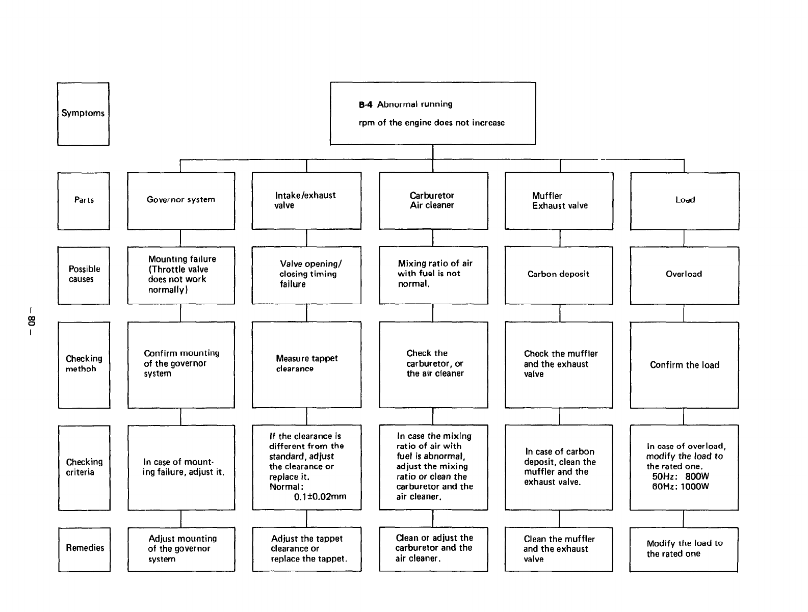
-
7
Symptoms
Checking
methoh
Checking
criteria
El
Remedies
B-4 Abnormal running
rpm of the engine does not increase
0
Governor system
Mounting failure
(Throttle valve
does not work
normally)
Confirm mounting
of the governor
system
In case of mount-
ing failure, adjust it.
r 1
Adjust mounting
of the governor
system
Intake/exhaust
valve
I
Valve opening/
closing timing
failure
--‘I-’
I
Measure tappet
clearance
If the clearance is
different from the
standard, adjust
the clearance or
replace it.
Normal :
0.1 +O.O2mm
I
Carburetor
Air cleaner
Mixing ratio of air
with fuel is not
normal.
I
Check the
carburetor, or
the air cleaner
In case the mixing
ratio of air with
fuel is abnormal,
adjust the mixing
ratio or clean the
carburetor and the
air cleaner.
r-
Muffler
Exhaust valve
G
Carbon deposit
Chock the muffler
and the exhaust
valve
In case of carbon
deposit, clean the
muffler and the
exhaust valve.
I
Clean the muffler
and the exhaust
valve
Load
Over load
I
I
I
Confirm the load
In case of overload,
modify the load to
the rated one.
50Hz: 800W
60Hz: 1ooow
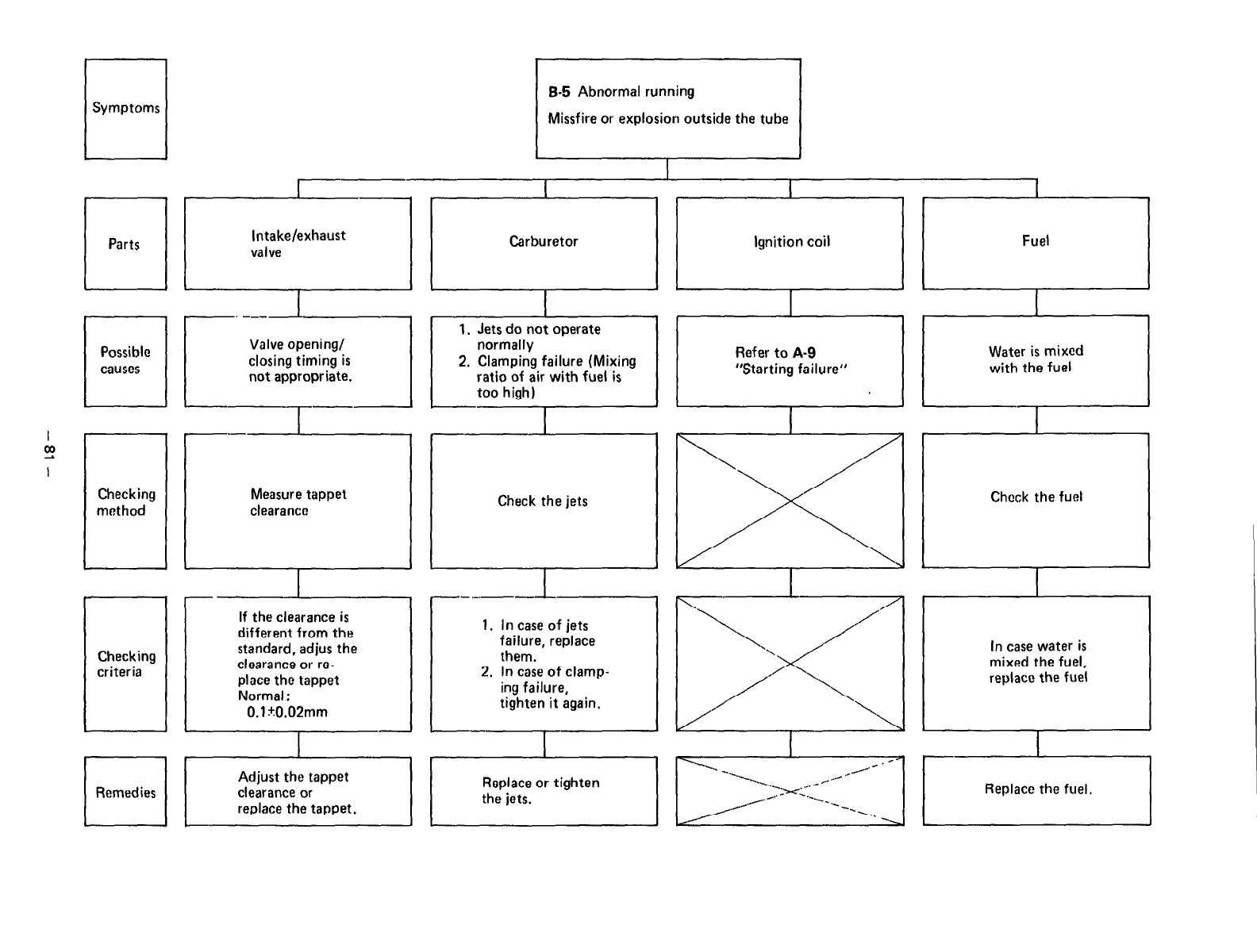
I I I
B-5 Abnormal running
Symptoms Missfire or explosion outside the tube
c
I
I
Parts Intake/exhaust
valve
I
Carburetor
I
I I
Ignition coil Fuel
r I
1. Jets do not operate III
Checking
i
criteria
Measure tappet
clearance
If the clearance is
different from the
standard, adjus the
clearance or rc-
place the tappet
Normal :
0.1 +O.O2mm
I
1 I I
I I
Remedies Adjust the tappet
clearance or
replace the tappet,
Check the jets
1. In case of jets
failure, replace
them.
2. In case of clamp-
ing failure,
tighten it again.
Check the fuel
In case water is
mixed the fuel,
replace the fuel
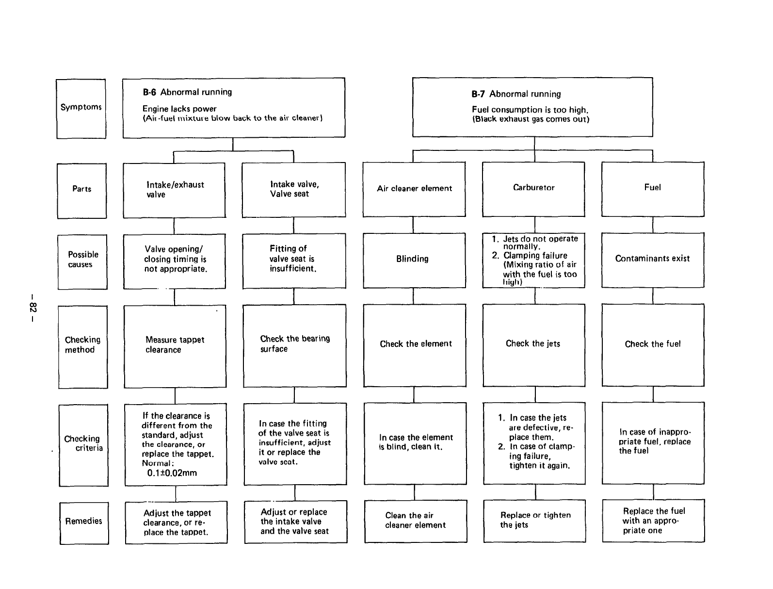
u
Symptoms
]I
(Air-fuel mixture blow back to the air cleaner)
B-7 Abnormal running
Fuel consumption is too high.
(Black exhaust gas comes out)
1
I 1
I
Intake/exhaust
valve
Valve opening/
closing timing is
not appropriate.
‘7-I
Air cleaner element
il
Fuel
a
intake valve,
Valve seat
Fitting of
valve seat is
insufficient,
Carburetor
Blinding
__:
2. Clamping failure
(Mixing ratio of air
with the fuel is too
Contaminants exist
‘,
Checking
method Measure tappet
clearance
Check the bearing
surface Check the jets Check the fuel
Check the element
1
If the clearance is
different from the
standard, adjust
the clearance, or
replace the tappet.
Normal :
0.1 +O.O2mm
1. In case the jets
are defective, re-
place them.
2. In case of clamp-
ing failure,
tighten it again.
In case the fitting
of the valve seat is
insufficient, adjust
it or replace the
valve seat.
In case of inappro-
priate fuel, replace
the fuel
Checking
criteria In case the element
is blind, clean it.
I
I
.A
q
Remedies
/
1 Erii;e or tighten /
Adjust or replace
the intake valve
and the valve seat
Adjust the tappet
clearance, or re-
place the tappet.
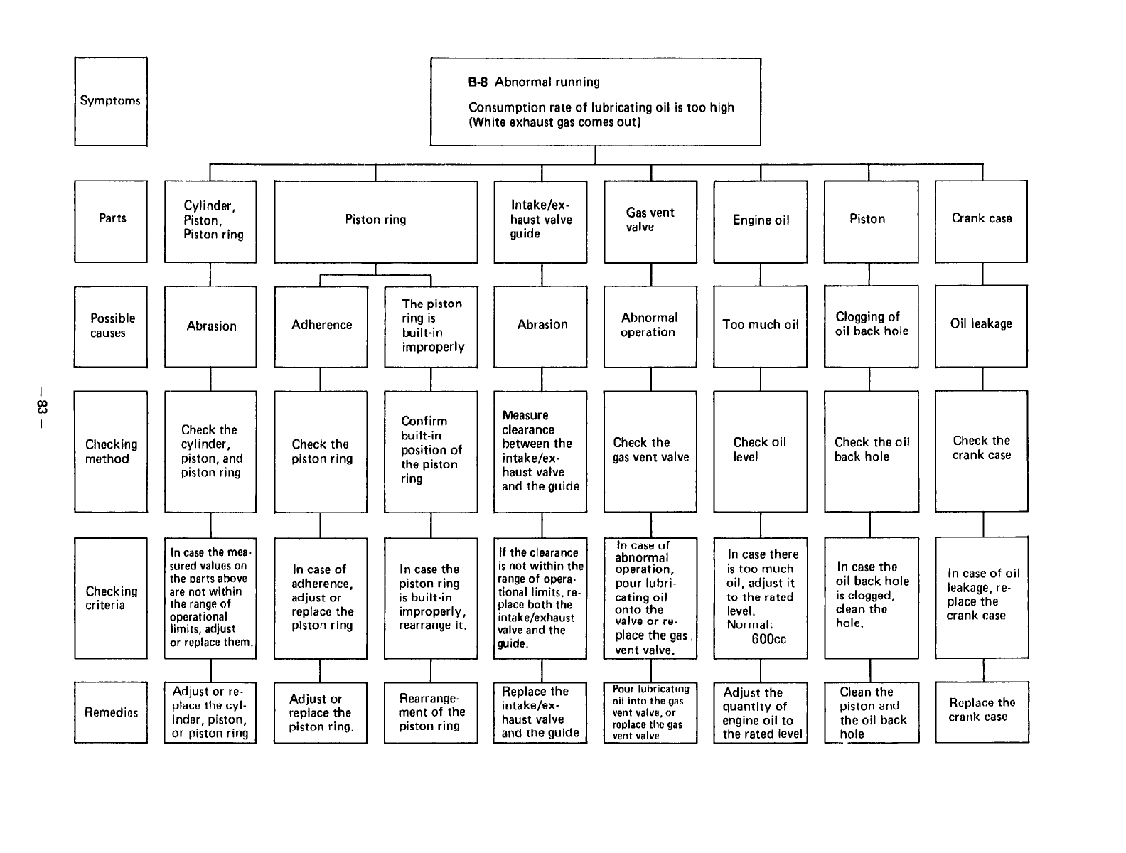
,
B-8 Abnormal running
Consumption rate of lubricating oil is too high
(White exhaust gas comes out)
I
_-..-
Piston ring
I
Intake/ex-
haust valve
guide
I
Gas vent
valve
I
Engine oil
Checking
criteria
sured values on
are not within
In case
of In case the
adherence, piston ring
adjust or is built-in
replace the improperly,
piston ring rearrange it.
If the clearance
is
not within the
range of opera.
tional limits, re-
J
place both the
intake/exhaust
valve and the
guide.
In case of
abnormal
operation,
pour lubri-
cating oil
onto the
valve or re-
place the gas
vent valve.
-l-
I
In case there
is too much
oil, adjust it
to the rated
level,
Normal:
6OOcc
I
In case the
oil back hole
is clogged,
clean the
hole.
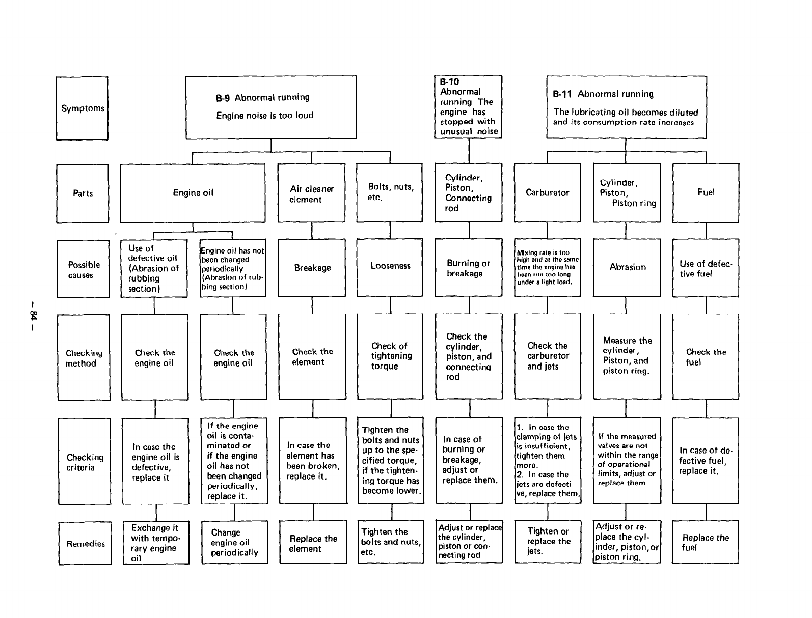
B-9 Abnormal running
Engine noise is too loud
I
Engine oil
Engine oil has not
been changed
periodically
r
(Abrasion of rub
hing section)
I
If the engine
oil is conta-
minated or
if the engine
oil has not
been changed
periodically,
replace it.
In case the
element has
been broken,
replace it.
I---- -
B-l 1 Abnormal running
7
The lubricating oil becomes diluted
and its consumption rate increases
I
bolts and nuts
become lower.
Burning or
n
breakage
r
Carburetor
I
Cylinder,
Piston,
Piston ring
I
Fuel
In case of
burning or
breakage,
adjust or
replace them.
Mixing rate is too
high md al the same
time the cngino has
tmen run 100 long
under a light lord.
ve, replace them
Abrasion
1
If the measured
valves are not
within the range
of operational
limits, adjust or
replace them
In case
of do-
fective fuel,
replace it,
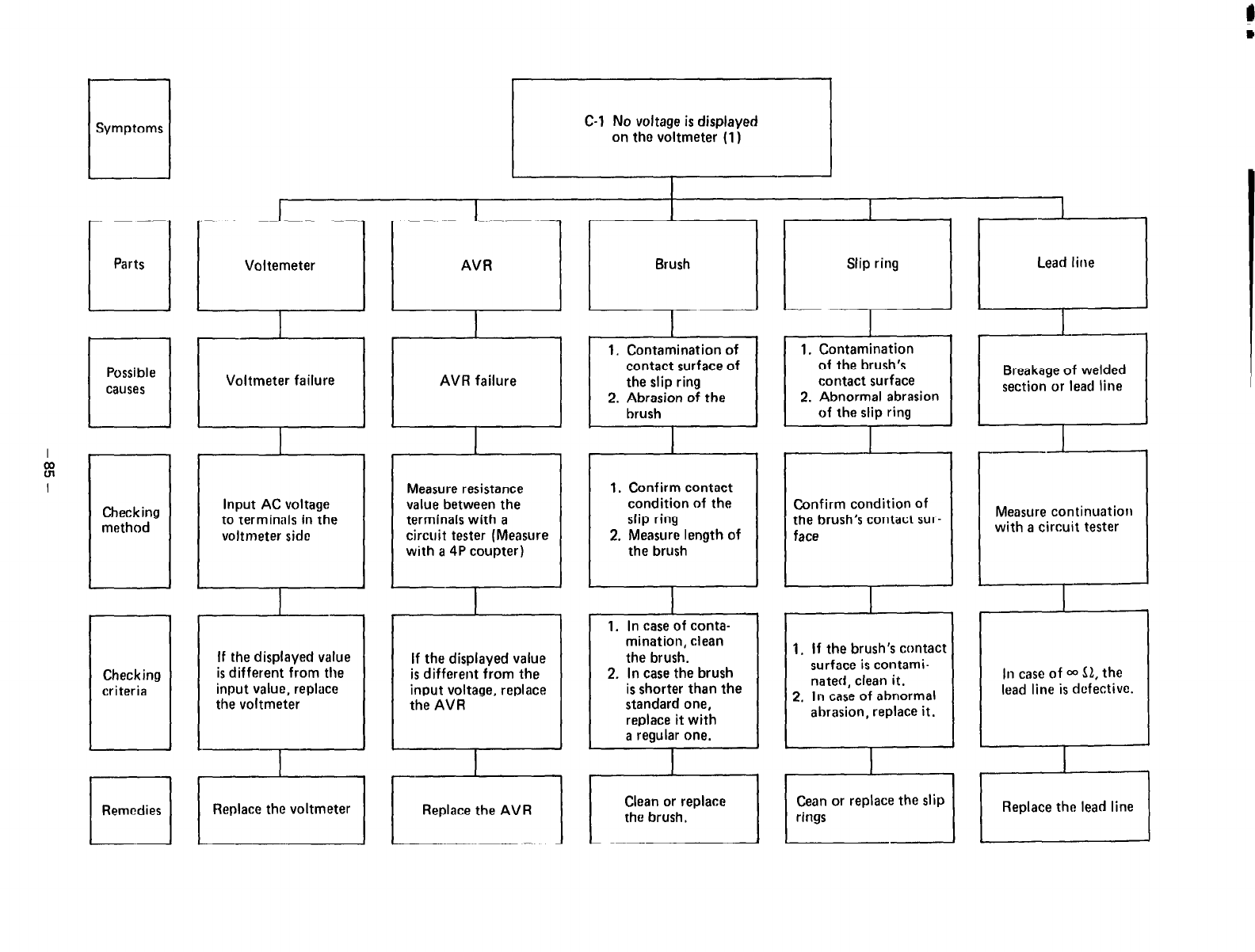
1
Symptoms
Checking
method
u
Remedies
C-l No voltage is displayed
on the voltmeter (1 I
I
Voltemeter
Voltmeter failure
Input AC voltage
to terminals in the
voltmeter side
If the displayed value
is different from the
input value, replace
the voltmeter
I
AVR
AVR failure
Measure resistance
value between the
terminals with a
circuit tester (Measure
with a 4P coupter)
-l--
If the displayed value
is different from the
input voltage, replace
the AVR
Brush
contact surface of
2. Abrasion of the
1. Confirm contact
condition of the
slip ring
2, Measure length of
the brush
1. In case of conta-
mination, clean
the brush.
2. In case the brush
is shorter than the
standard one,
replace it with
a regular one.
Clean or replace
the brush.
l-7
Slip ring
I J
1. Contamination
of the brush’s
contact surface
2. Abnormal abrasion
of the slip ring
Confirm condition of
the brush’s contact sur-
face
1. If the brush’s contact
surface is contami-
nated, clean it.
2. In case of abnormal
abrasion, replace it.
Cean or replace the slip
rings
Lead line
I
Breakage of welded
section or lead line
Measure continuation
with a circuit tester
111
case
of 00 52, the
lead line is defective.
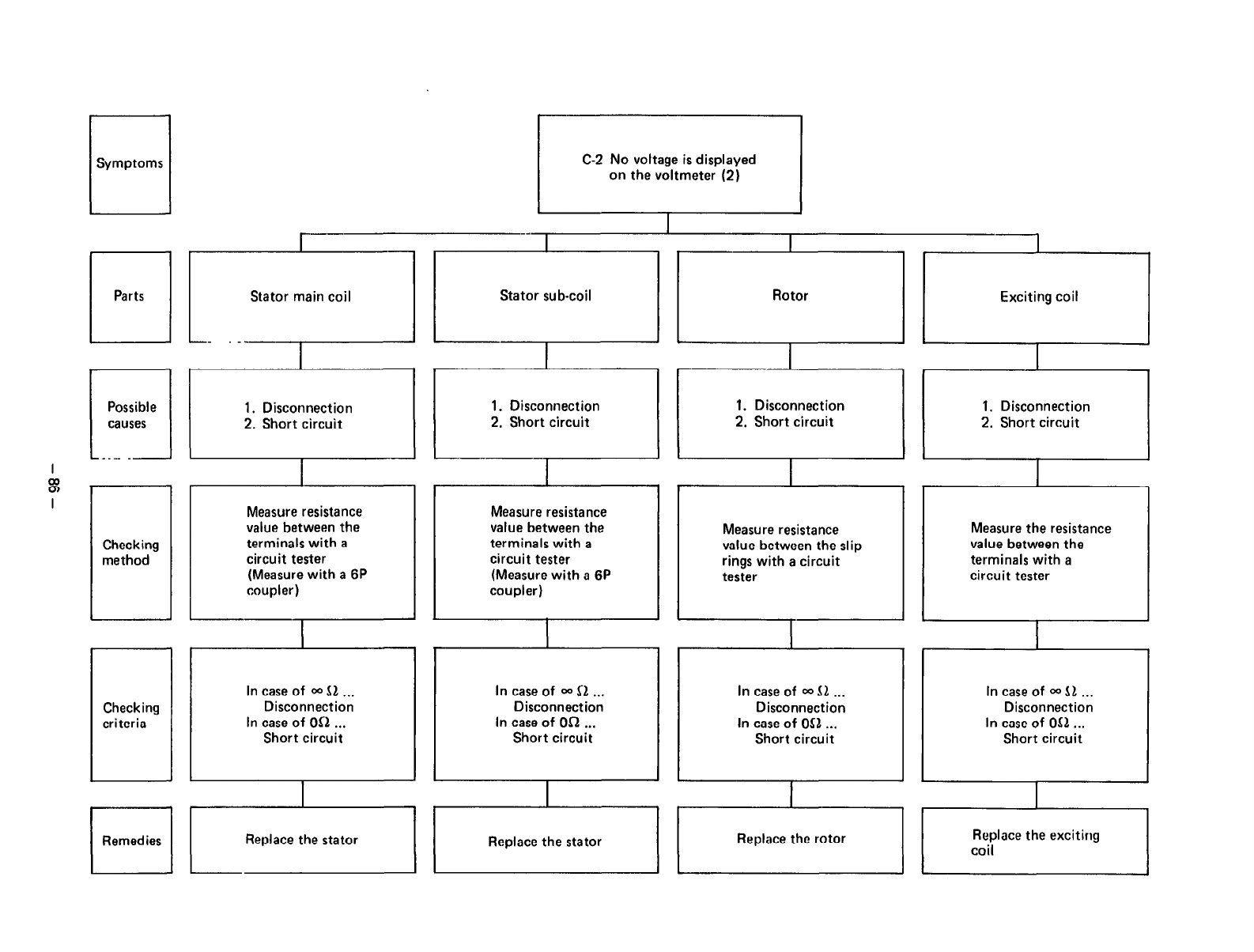
C-2 No voltage is displayed
on the voltmeter (2)
Stator sub-coil
I
Rotor
1
Exciting coil
1. Disconnection
2. Short circuit
I
1. Disconnection
2. Short circuit
-.----
1. Disconnection
2. Short circuit 1. Disconnection
2. Short circuit
I
Checking
method
Checking
criteria
I
I Measure resistance
value between the
terminals with a
circuit tester
(Measure with a 6P
coupler)
In case of * $1 . . .
Disconnection
In case of OS1 . . .
Short circuit
I
Measure resistance
value between the
terminals with a
circuit tester
(Measure with a 6P
coupler)
In case of OQ Sl .., In case of 00 dl . . .
Disconnection Disconnection
In case of On . . . In case of
OS1
. . .
Short circuit Short circuit
Measure resistance
value between the slip
rings with a circuit
tester
Measure the resistance
value between the
terminals with a
circuit tester
In case of 00
$1 . . .
Disconnection
In case of
Oil...
Short circuit
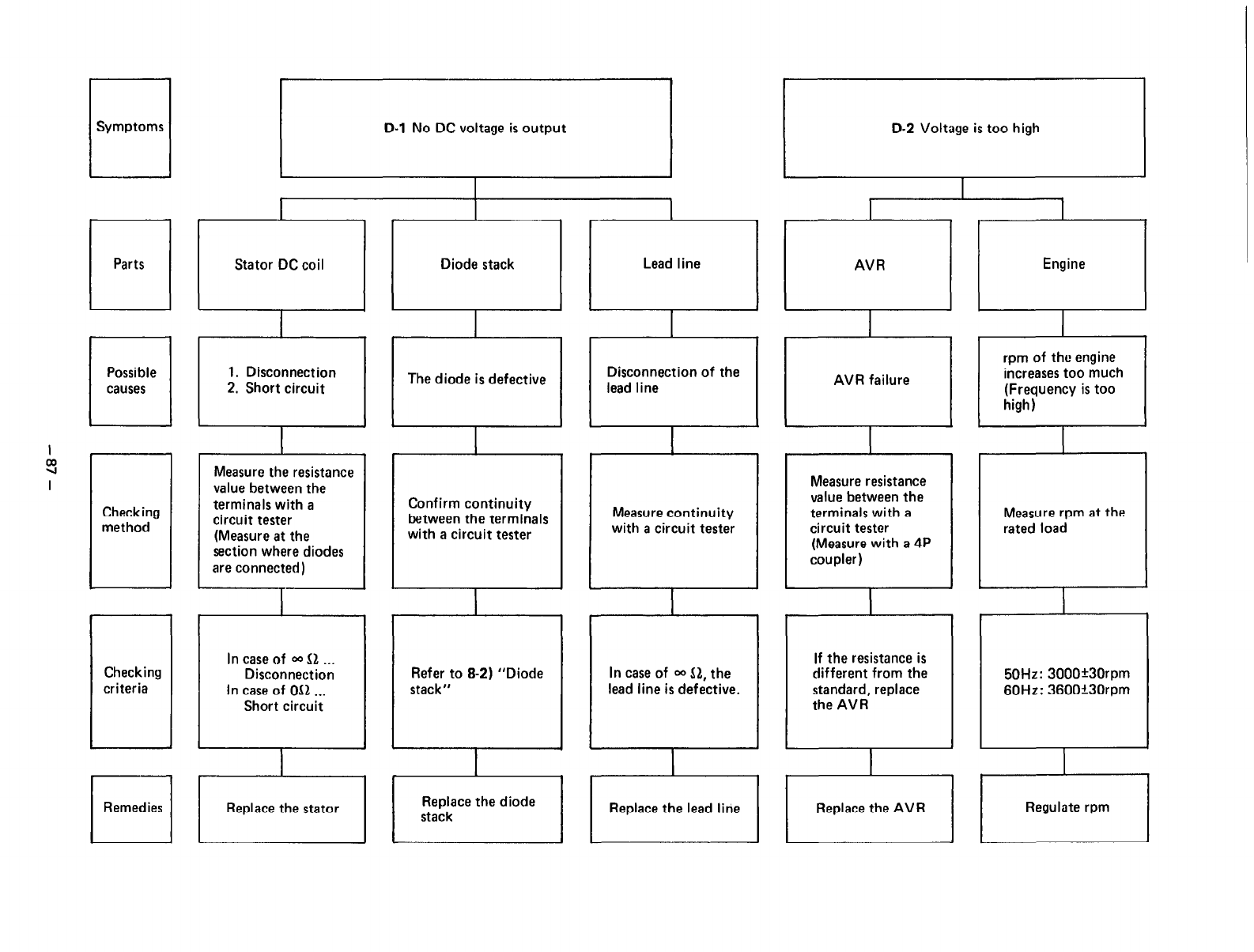
I
2
I
Symptoms
D-l
No DC voltage is output ( 1
D-2 Voltag,eistoo high
q
Parts
Possible
q
causes
I
Stator DC coil
1. Disconnection
2. Short circuit
I
Diode stack
The diode is defective
I
Lead line
Disconnection of the
lead line
AVR
AVR failure
Checking
method
L
Remedies
I
Measure the resistance
value between the
terminals with a
circuit tester
(Measure at the
section where diodes
are connected)
In case of OQ
bl
. . .
Disconnection
In case of
Oil . . .
Short circuit
r
Replace the stator
I
Confirm continuity
between the terminals
with a circuit tester
Refer to 8-2) “Diode
stack”
Replace the diode
stack
Measure continuity
with a circuit tester
In case of 00
51,
the
lead line is defective.
Replace the lead line
Measure resistance
value between the
terminals with a
circuit tester
(Measure with a 4P
coupler)
If the resistance is
different from the
standard, replace
the AVR
rpm of the engine
increases too much
(Frequency is too
Measure rpm at the
rated load
50Hz: 3000+30rpm
60Hz: 3600”30rpm
Regulate rpm
L
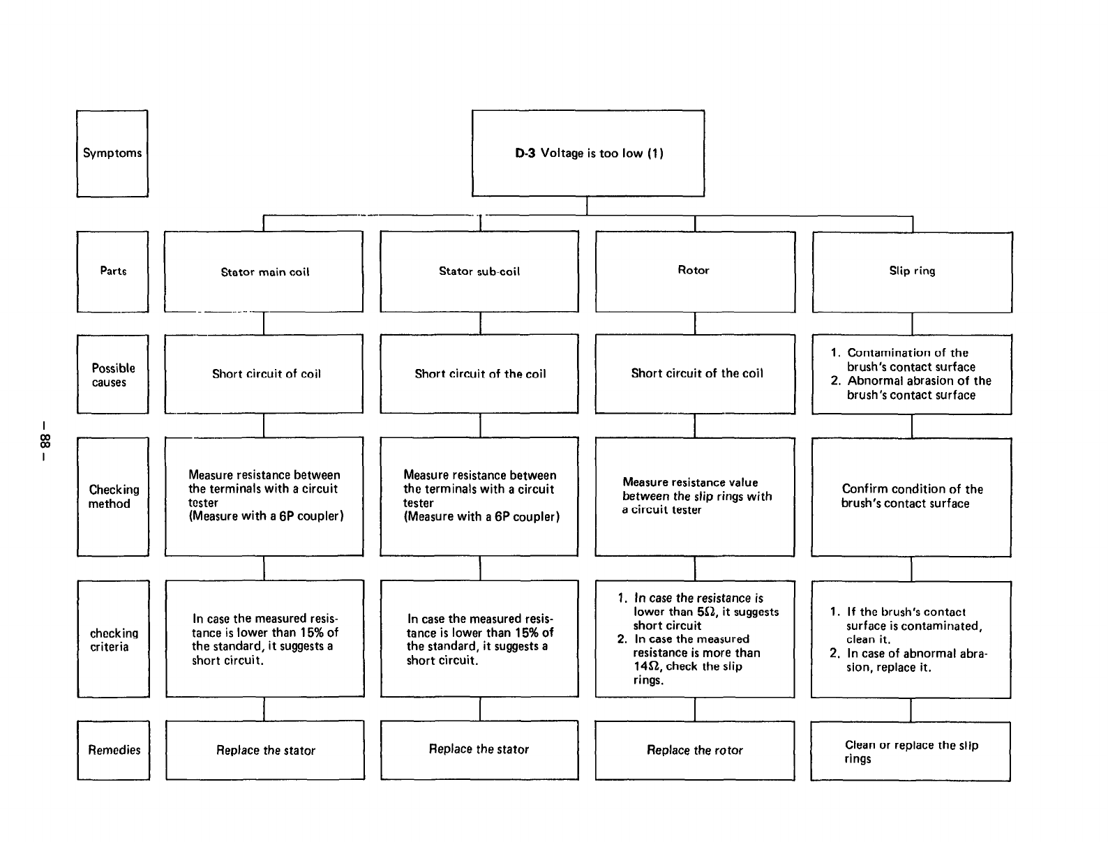
I
Ez
I
L
Symptoms
Possible
q
causes
Checking
method
checking
criteria
Remedies
-.. -
Stator sub.coil
I
I
Rotor Rotor Slip ring Slip ring
1
I
Short circuit of the coil Short circuit of the coil Short circuit of the coil Short circuit of the coil
---- ----
I
I. Contamination of the I. Contamination of the
brush’s contact surface brush’s contact surface
2. Abnormal abrasion of the 2. Abnormal abrasion of the
brush’s contact surface brush’s contact surface
Measure resistance between
the terminals with a circuit
tester
(Measure with a 6P coupler)
I
In case the measured resis-
tance is lower than 15% of
the standard, it suggests a
short circuit.
/
Measure resistance between
the terminals with a circuit
tester
(Measure with a 6P coupler)
In case the measured resis-
tance is lower than 15% of
the standard, it suggests a
short circuit.
Measure resistance value
between the slip rings with
a circuit tester
1. In case the resistance is
lower than 553, it suggests
short circuit
2. In case the measured
resistance is more than
1452, check the slip
rings.
Confirm condition of the
brush’s contact surface
1. If the brush’s contact
surface is contaminated,
clean it.
2. In case of abnormal abra.
sion, replace it.
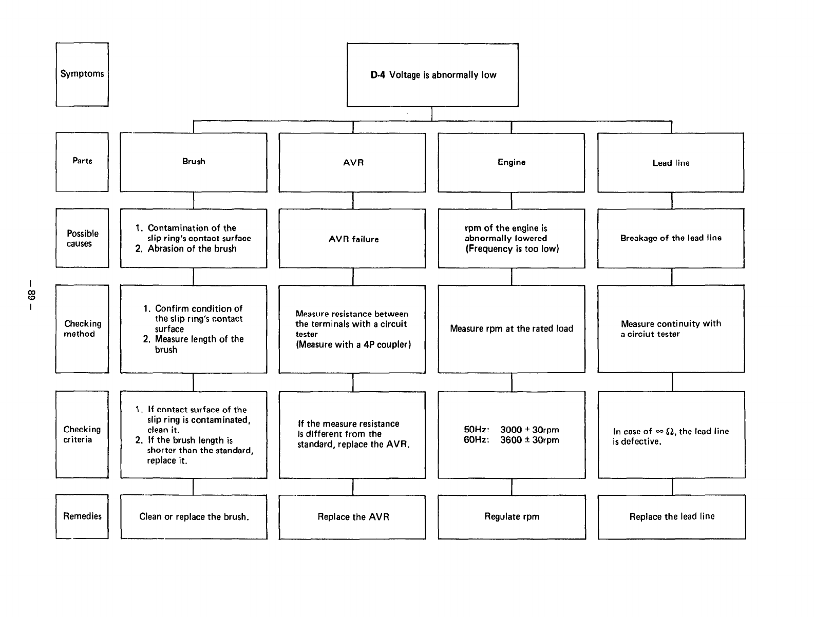
q
Symptoms D-4 Voltage is abnormally low
I I
_-
Ll
r -.
I I
I I
Parts Brush AVR Engine Lead line
I I I I
1
;I Fi c ’ Fl Breakage of lhe lead line
AVR failure
I
Checking
method
Checking
criteria
1. Confirm condition of
the slip ring’s contact
surface
2. Measure length of the
brush
1. If contact surface of the
slip ring is contaminated,
clean it.
2. If the brush length is
shorter than the standard,
replace it.
Measure resistance between
the terminals with a circuit
tester
(Measure with a 4P coupler)
If the measure resistance
is different from the
standard, replace the AVR.
Measure rpm at the rated load
50Hz: 3000 * 30rpm
60Hz: 3600 + 30rpm
Measure continuity with
a circiut tester
In case of 00
Sl,
the lead line
is defective.
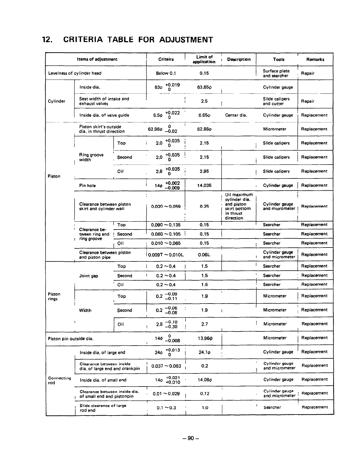
12. CRITERIA TABLE FOR ADJUSTMENT
Items of adjustment I
Criteira ! Limit of ’
application I Description Tools Remarks
I
Levelness of cylinder head Below 0.1 0.15 j Surface plate !
and searcher : Repair
Inside dia. 63Q +0.019
0 53.650 Cylinder gauge
I
Cylinder Seat width of intake and
exhaust valves I I 2.5 Slide calipers
I and cutter Repair
(
I
Inside dia. of valve guide +0.022
6.50 o 6.650 Center dia. Cylinder gauge 1 Replacement
I
Piston skit-t’s outside 0 ;
dia. in thrust direction 62.980 --o.o2 62.880 Micrometer Replacement
,
L
TOP ; .
2 0 +0.035 i
0 ; 2.15 I Slide calipers Replacement
I
Ring groove ’ Second 2.0 :.035 ! 2.15 ( ~~ I
i width i Slide calipers 1 Replacement
Piston Oil 2.* +0.035 ;
0 I 2.95 ( Slide calipers Replacement
Pin hole
Clearance between piston
skirt and cylrnder wall
! Top
r Clearance be-
tween ring and ! Second
I ring groove I Oil
I +0002 I
‘4 -0:oos 1 14.035 , Cylinder gauge i Replacement
i Oil maximum i
: cylinder dia. ! ;
’ 0.020 -0.059 , 0.25 ’ ;;ftip~~om Cylinder gauge
and micrometer i Rep’acement
I in thrust
1 direction I
0.090 -0.135 0.15 i Searcher Replacement
’ 0.060-0.105 ! 0.15 i Searcher Replacement
: 0.010 -0.065 0.15 I Searcher Replacement
Clearance between piston
and piston pipe i 0.009T -O.OlOL 0.06L Cylinder gauge ! Replacamant
r and micrometer
Joint gap
Top
I 0.2
-0.4 !
Second i 02-0.4 )
1.5 r Searcher
1.5 ’ Searcher
I
! Replacement
: Replacement
Piston
rings
’ Oil
TOP
I
0.2 5 0.4
o 2 -0.09
. -0.11
1.5 / Searcher Replacement
1.9 Micrometer / Replacement
Width Second
-0.06 :
Oa2 -0.08 1.9
I
Micmmeter : Replacement
I I Oil I 2.B -0.10 i
-0.30 j 2.7 : Micrometer Replacement
I I
Piston pin outside dia. 14’ 1.00s 13.969 Micrometer i Replacement
I
Inside dia. of large end 240 o
+0.013 ; 24.1~ : Cylinder gauge Replacement
/ ,“;;;~l~~;;~;~;~~kpin / 0.037 -0.063 ; 0.2 Cylinder gauge
and micrometer Replacement
I
Connecting Inside dia. of small end +0.021
rod 14Q +0.010 14.080 Cylinder gauge Replacement
I
Clearance between inside dia. 0.01 -0.029 ) 0.12 Cylinder gauge
I of small end and pistonpin and micrometer ! Replacement
I
! Sl;;;earance of large 0.1 -0.3 1 .o 1 ’ Searcher Replacement
I I
-9o-
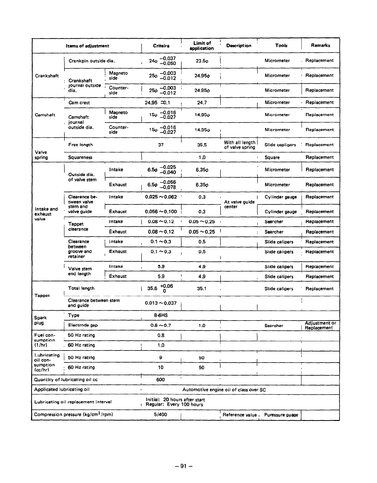
Items of adjustment
I
I Criteira I Limit of ! Dercription !
application Tools Remarks
/ Crankpin outside dia. -0.037
’ 240 -0.050 1
23.50 / Micrometer , Replacement
t I
I
Crankshaft ; Magneto
Crankshaft 1 side 250 ro”:g; ; !
24.950 ; Micrometer : Replacement
:
journal outside , dia. Counter- 1 250 -0.003 :
side -0.012 24.950 Micrometer Replacement
’ Cam crest 24.95 a.1 ! 24.7 ! Micrometer 8 Replacement
!
Camshaft 1 Magneto -0.016
Camshaft side Micrometer
I ,50 -0.027 14.950 Replacement
journal
outside dia.
I
I
Counter- I
side ,% -0.016
-0.027 14.956 ! Micrometer Replacement
I
Free length 37 I 35.5 With all length i I
of valve spring Slide ,.eplipers Replacement I
Valve I
ipring Squareness I 1.0 a Square Replacement
i
Outside dia.
of valve stem
Intake
Exhaust
6.50 -$E ;
I
6.50
-0.056
-0.078
6.350 , Micrometer \ Replacement
I
6.350 Micrometer Replacement
Clearance be- Intake 0.025 -0.062 ’ 0.3 8 I Cylinder gauge
tween valve At valve guide
stem and I I center I
1 Replacement ’
Intake and
exhaust valve guide
Exhaust
0.056 -0.100 j 0.3 I ( Cylinder gauge i Replacement
falve
Tappet
Intake i 0.08-0.12 : 0.05-0.25 8 : Searcher : Replacement
1 clearance
I Exhaust 0.08-0.12 ’ 0.05 -0.25 1 : Searcher i Replacement
Clearance
between
groove and
retainer
/ Intake , 0.1 -0.3 0.5
Exhaust 0.1 -0.3 ! 0.5
I : Slide calipers ! Replacement
Slide calipers Replacement
’ Valve stem
end
length
Intake ,
1
! Exhaust
5.9
5.9 ’
4.9
4.9
Slide calipers 1 Replacement
Slide calipers Replacement
rappet
Total length j 35.6 q-O6 35.1 I Slide calipers
I
Replacement
Clearance between stem
and guide 0.013 -0.037 i I
spark ’ Type
1lug i Electrode gap
-uel con-
50 Hz rating
umption f
,l/hr) 60 HE rating
-ubricaing i
50
Hz
rating
,il con-
;umption
cchr) ; 60 Hz rating
86HS
I
0.6 -0.7 1.0 Searcher Adjustment or
! Replacement
0.8 ) !
1 .o
I I
I
9 / 50
I !
10 50 I I
luantiry of lubricating oil cc
!
600 ’ I
dpplicated lubricating oil Automotive engine oil of class over SC
-ubricating oil replacement interval Initial: 20
hours
after start
I Regular: Every 100 hours
Compression pressure (kg/cm’/rpm) wloo
I
: Reference value , Puressure guage ,
- 91 -
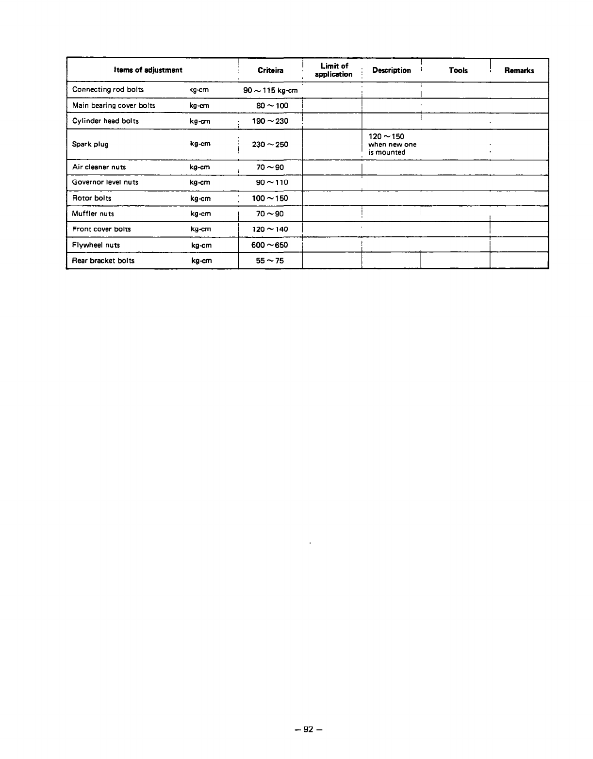
! )
Items of adjustment I
Criteira Limit of
application ; Description i Tools ! Remarks
Connecting rod bolts kg-cm 90-115 kg-cm I
Main bearing cover bolts kg-cm 805100 !
Cylinder head bolts kg-cm : 190-230 !
Spark plug
Air cleaner nuts
Governor level nuts
I
kg-cm j 230-250 /
kg-cm i 70 -90
kg-cm go-110
I
Rotor bolts kgcm : 100-150 I
Muffler nuts kg-cm I 70 -90
Front cover bolts kg-cm I
! 1202140 /
I
Flywheel nuts kg-cm 1 600 -650 j I
1 I
I
I
Rear bracket bolts kg- I 55-75 I I I
I
- 92 -
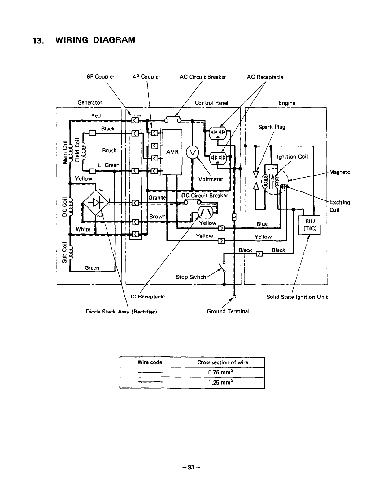
13. WIRING DIAGRAM
6P Coupler 4P Coupler AC Circuit Breaker AC Receptacle
Generator \ /ntroI Panel / Engine
Spark Plug
;
i LT-Tw
Yellow
I I -
--mm I I il
Diode Stack Assy (Rectifier) Ground Terminal
I I
Wire code I Cross section of wire
I
Magneto
Exciting
Coil
I I
0.75 mm2
I
I
em---
l
1.25 mm2 I
-93-
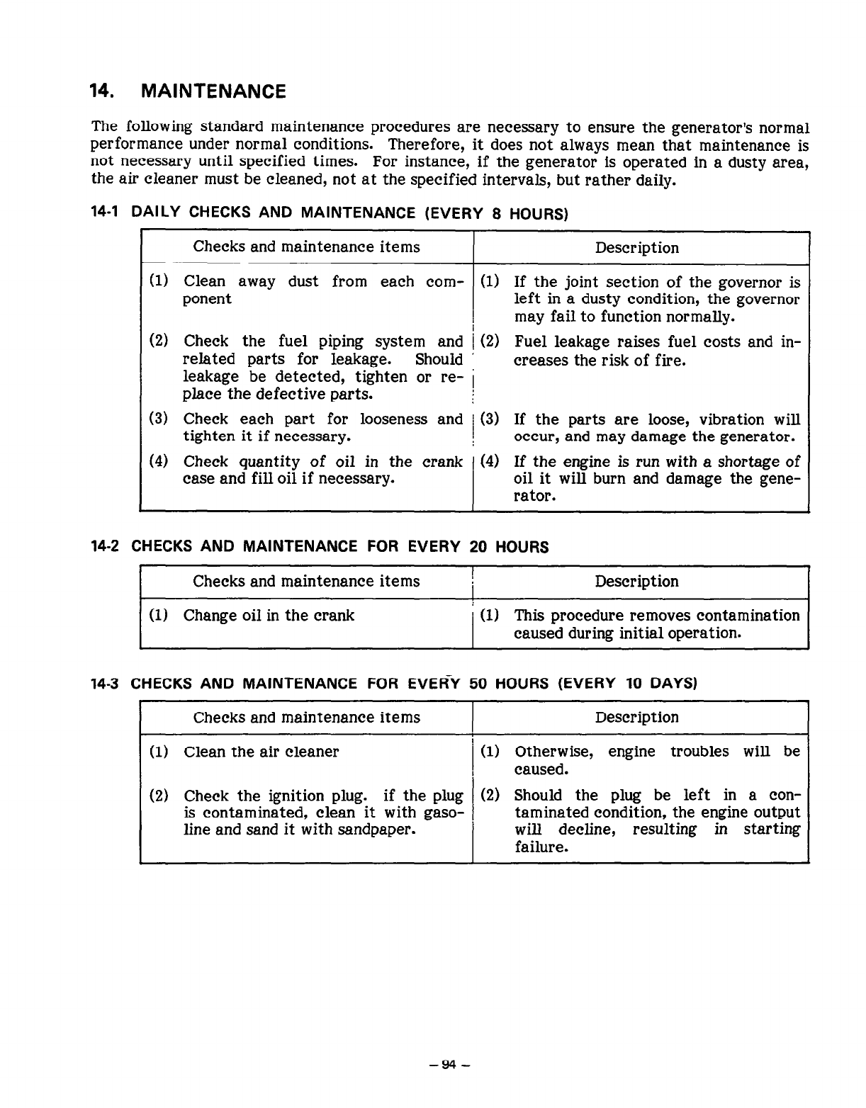
14. MAINTENANCE
The following standard maintenance procedures are necessary to ensure the generator’s normal
performance under normal conditions. Therefore, it does not always mean that maintenance is
not necessary until specified times. For instance, if the generator is operated in a dusty area,
the air cleaner must be cleaned, not at the specified intervals, but rather daily.
14-1 DAILY CHECKS AND MAINTENANCE (EVERY 8 HOURS)
r
Checks and maintenance items Description
(1)
(2)
(3)
(4)
Clean away dust from each corn- (1
ponent ) If the joint section of the governor is
left in a dusty condition, the governor
may fail to function normally.
) Fuel leakage raises fuel costs and in-
creases the risk of fire.
Check the fuel piping system and 1 (2
related parts for leakage. Should ’
leakage be detected, tighten or re- i
place the defective parts.
Check each part for looseness and 1 (3) If the parts are loose, vibration will
tighten it if necessary. I occur, and may damage the generator.
Check quantity of oil in the crank 1 (4) If the engine is run with a shortage of
case and fill oil if necessary. oil it will burn and damage the gene-
rator.
14-2 CHECKS AND MAINTENANCE FOR EVERY 20 HOURS
I
Checks and maintenance items !
I Description
(1) Change oil in the crank I (11 This procedure removes contamination
caused during initial operation.
14-3 CHECKS AND MAINTENANCE FOR EVERY 50 HOURS (EVERY 10 DAYS)
I
Checks and maintenance items I Description
(1) Clean the air cleaner
(2) Check the ignition plug. if the plug
is contaminated, clean it with gaso-
line and sand it with sandpaper.
(1) Otherwise, engine troubles will be
caused.
(2) Should the plug be left in a con-
taminated condition, the engine output
will decline, resulting in starting
failure.
-94-
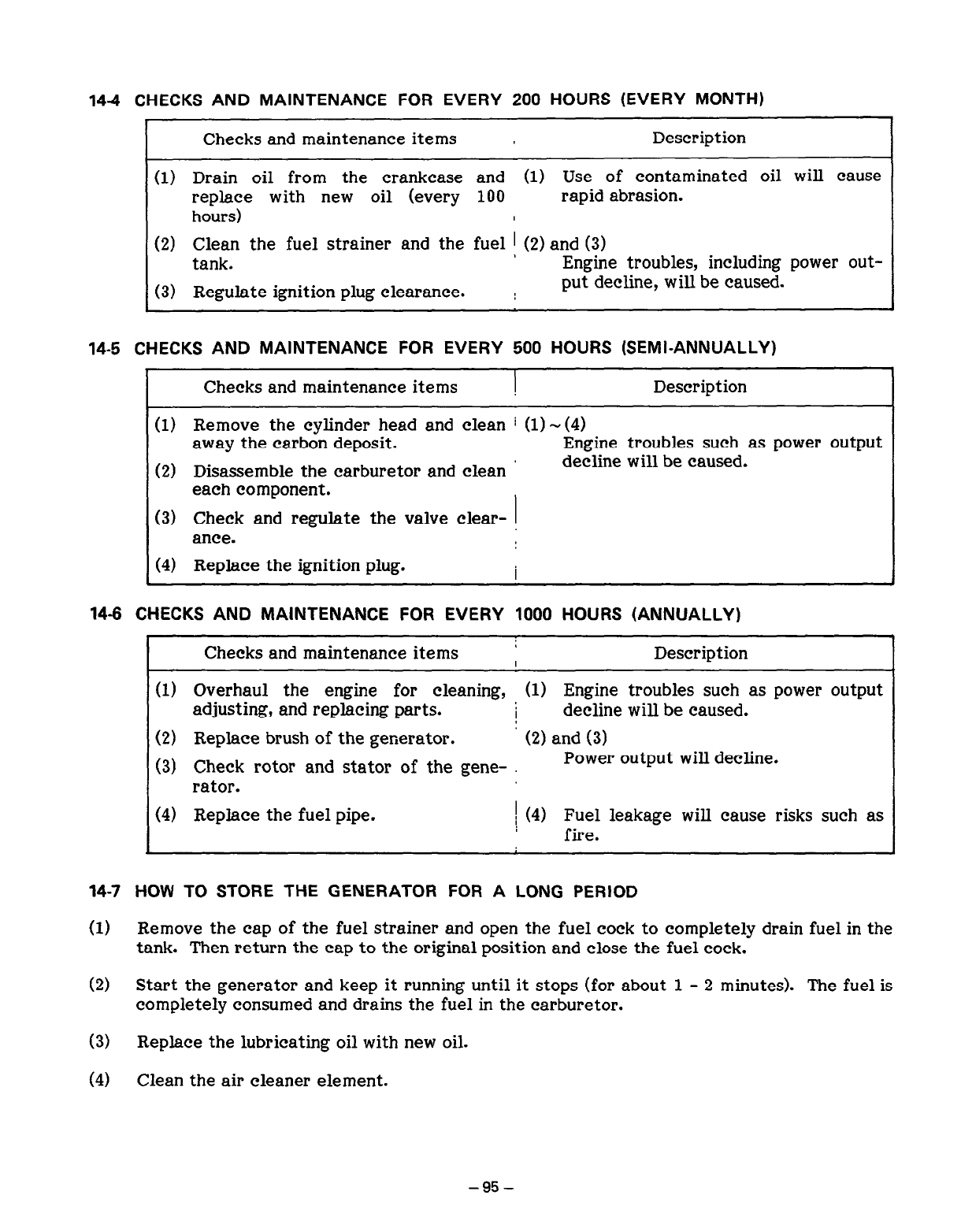
144 CHECKS AND MAINTENANCE FOR EVERY 200 HOURS (EVERY MONTH)
I
Checks and maintenance items I Description
(1) Drain oil from the crankcase and (1) Use of contaminated oil will cause
replace with new oil (every 100 rapid abrasion.
hours) I
(2) E;p the fuel strainer and the fuel ! (2) and (3)
a Engine troubles, including power out-
(3) Regulate ignition plug clearance. : put decline, will be caused.
14-5 CHECKS AND MAINTENANCE FOR EVERY 500 HOURS (SEMI-ANNUALLY)
1
Checks and maintenance items ! Description
(1) Remove the cylinder head and clean / (1) - (4)
away the carbon deposit. Engine troubles such as power output
(2) Disassemble the carburetor and clean decline will be caused.
each component.
~ (3) Check and regulate the valve clear-
ante.
~ (4) Replace the ignition plug. I
14-5 CHECKS AND MAINTENANCE FOR EVERY 1000 HOURS (ANNUALLY)
I
Checks and maintenance items : Description
(1) Overhaul the engine for cleaning, (1) Engine troubles such as power output
adjusting, and replacing parts. I decline will be caused.
(2) Replace brush of the generator. (2) and (3)
(3) Check rotor and stator of the gene- Power output will decline.
rator.
(4) Replace the fuel pipe. ( (4) Fuel leakage will cause risks such as
fire.
14-7 HOW TO STORE THE GENERATOR FOR A LONG PERIOD
(1) Remove the cap of the fuel strainer and open the fuel cock to completely drain fuel in the
tank. Then return the cap to the original position and close the fuel cock.
(2) Start the generator and keep it running until it stops (for about 1 - 2 minutes). The fuel is
completely consumed and drains the fuel in the carburetor.
(3) Replace the lubricating oil with new oil.
(4) Clean the air cleaner element.
-95-
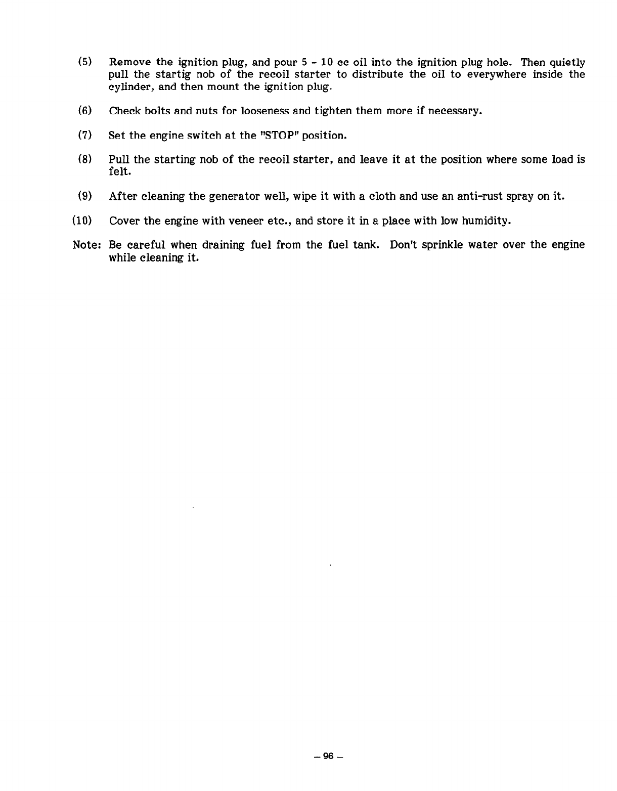
(5)
(6)
(7)
(8)
(9)
(10)
Remove the ignition plug, and pour 5 - 10 cc oil into the ignition plug hole. Then quietly
pull the startig nob of the recoil starter to distribute the oil to everywhere inside the
cylinder, and then mount the ignition plug.
Check bolts and nuts for looseness and tighten them more if necessary.
Set the engine switch at the “STOP” position.
Pull the starting nob of the recoil starter, and leave it at the position where some load is
felt.
After cleaning the generator well, wipe it with a cloth and use an anti-rust spray on it.
Cover the engine with veneer etc., and store it in a place with low humidity.
Note: Be careful when draining fuel from the fuel tank. Don’t sprinkle water over the engine
while cleaning it.
- 96 -


1 ISSUE EMD-GS0095 1
@FUJI HEAVY INDUSTRIES LTD.
-
INDUSTRIAL PRODUCTS DIV.
2ND Subaru Bldg.
l-l, Choume, Miyahara-cho,
Omiya-shi, Saitama 330-0038, Japan
PHONE ; (Omiya 48) 653-5811
FACSIMILE ; (Omiya 48) 653-5691
PRINTED IN JAPAN
198444
