Sun Castle Global Precision Technology Co SCGPTDL0002 Wireless Electronic Lock User Manual SR6 9 Operation Manual FCC131015 copy

Sun Castle Global Precision Technology Co, Ltd. Wireless Electronic Lock SR6 9 Operation Manual FCC131015 copy
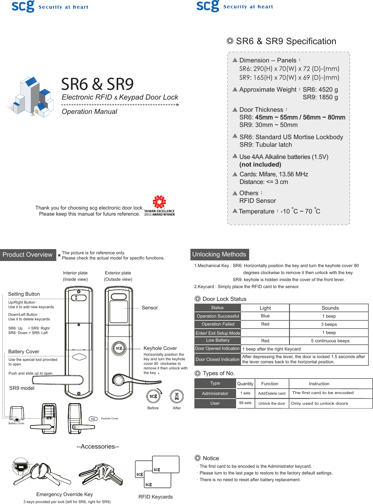
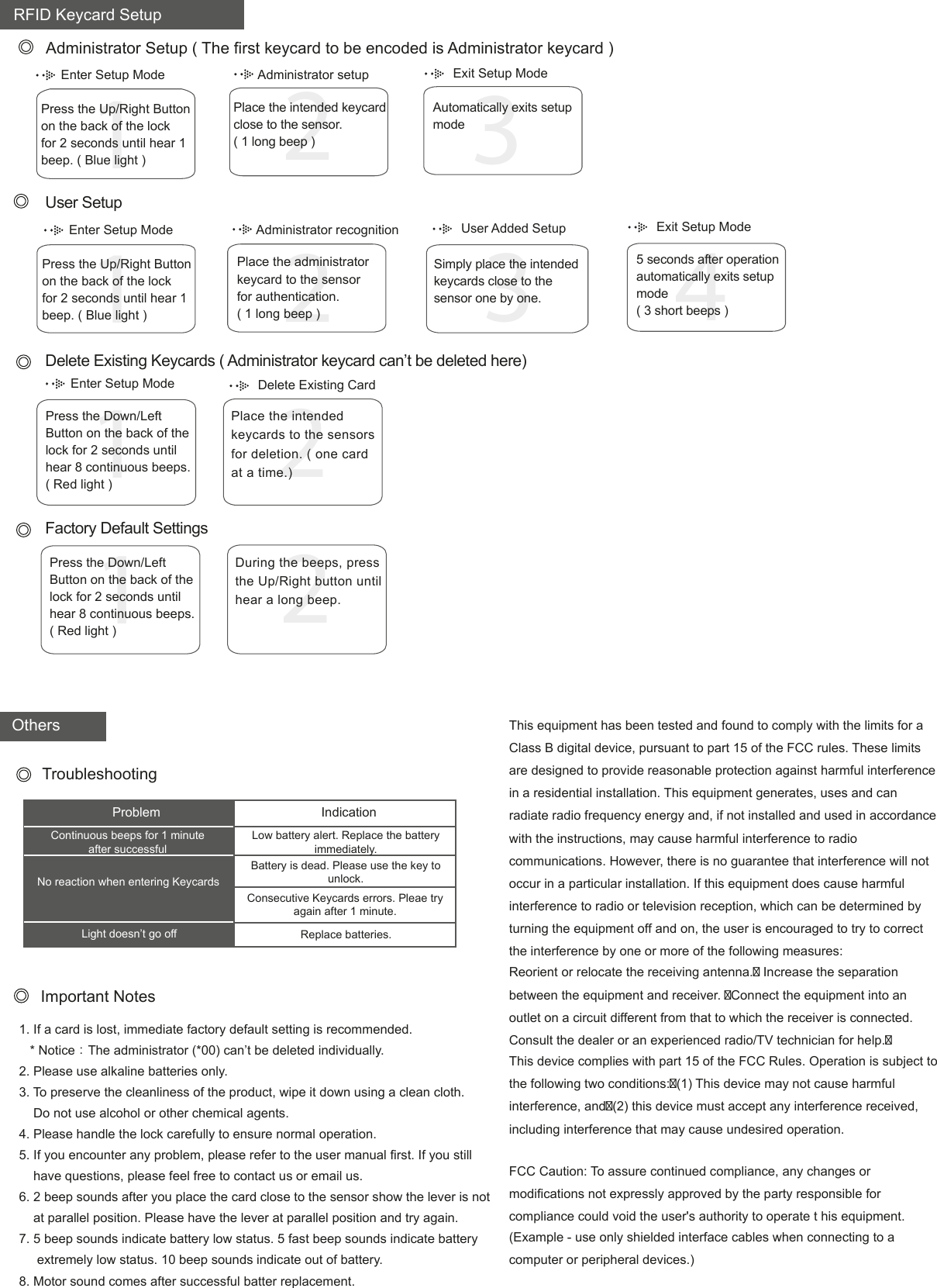
Users Manual

Before AfterProduct Overview The picture is for reference only. Please check the actual model for specific functions.Exterior plate(Outside view)Interior plate(Inside view)Setting ButtonUp/Right Button:Use it to add new keycardsDown/Left Button:Use it to delete keycardsSR6: Up     = SR9: RightSR6: Down = SR9: LeftBattery CoverUse the special tool providedto openPush and slide up to openSensorKeyhole CoverHorizontally position the key and turn the keyhole cover 90  clockwise to remove it then unlock with the key  --Accessories--Emergency Override Key3 keys provided per lock (left for SR6, right for SR9)RFID KeycardsDoor Lock StatusTypeAdministratorUserQuantity Function Instruction1 sets99 setsAdd/Delete cardUnlock the doorThe first card to be encodedTypes of No.StatusOperation SuccessfulOperation FailedEnter/ Exit Setup ModeLow BatteryDoor Opened IndicationDoor Closed IndicationLightBlueRedRed1 beep3 beeps1 beep5 continuous beepsSounds                      1 beep after the right KeycardAfter depressing the lever, the door is locked 1.5 seconds after the lever comes back to the horizontal position.Unlocking MethodsNotice.The first card to be encoded is the Administrator keycard..Please turn to the last page to restore to the factory default settings..There is no need to reset after battery replacement.1.Mechanical Key : SR6: Horizontally position the key and turn the keyhole cover 90                                            degrees clockwise to remove it then unlock with the key.                                SR9: keyhole is hidden inside the cover of the front lever.2.Keycard : Simply place the RFID card to the sensor.Electronic RFID & Keypad Door LockSR6 & SR9Operation ManualSR6 & SR9 SpecificationDimension -- Panels:SR6: 290(H) x 70(W) x 72 (D)-(mm)SR9: 165(H) x 70(W) x 69 (D)-(mm)Approximate Weight:SR6: 4520 g                                    SR9: 1850 gUse 4AA Alkaline batteries (1.5V)(not included)Others:RFID Sensor Door Thickness:SR6: 45mm ~ 55mm / 56mm ~ 80mmSR9: 30mm ~ 50mmSR6: Standard US Mortise LockbodySR9: Tubular latchTemperature:-10  C ~ 70  CCards: Mifare, 13.56 MHzDistance: <= 3 cmSR9 modelOnly used to unlock doorsBattery CoverKeyhole CoverThank you for choosing scg electronic door lock.Please keep this manual for future reference.
Enter Setup Mode Administrator setup Exit Setup Mode RFID Keycard SetupUser Setup132Press the Up/Right Buttonon the back of the lock for 2 seconds until hear 1 beep. ( Blue light )  Place the administrator   keycard to the sensor   for authentication.  ( 1 long beep )Delete Existing Keycards ( Administrator keycard can’t be deleted here)OthersProblemContinuous beeps for 1 minute after successful No reaction when entering KeycardsLight doesn’t go offLow battery alert. Replace the battery immediately.Battery is dead. Please use the key to unlock.Consecutive Keycards errors. Pleae try again after 1 minute.Replace batteries.IndicationTroubleshootingImportant Notes12Press the Down/Left Button on the back of thelock for 2 seconds until hear 8 continuous beeps.( Red light )Place the intended keycards to the sensorsfor deletion. ( one card at a time.)Administrator Setup ( The first keycard to be encoded is Administrator keycard ) 132Press the Up/Right Buttonon the back of the lock for 2 seconds until hear 1 beep. ( Blue light )Place the intended keycard close to the sensor.( 1 long beep )1. If a card is lost, immediate factory default setting is recommended.    * Notice:The administrator (*00) can’t be deleted individually.2. Please use alkaline batteries only.3. To preserve the cleanliness of the product, wipe it down using a clean cloth.    Do not use alcohol or other chemical agents.4. Please handle the lock carefully to ensure normal operation.5. If you encounter any problem, please refer to the user manual first. If you still     have questions, please feel free to contact us or email us.6. 2 beep sounds after you place the card close to the sensor show the lever is not     at parallel position. Please have the lever at parallel position and try again.7. 5 beep sounds indicate battery low status. 5 fast beep sounds indicate battery     extremely low status. 10 beep sounds indicate out of battery.8. Motor sound comes after successful batter replacement.Automatically exits setupmodeEnter Setup Mode Administrator recognition User Added Setup  Exit Setup Mode45 seconds after operationautomatically exits setupmode ( 3 short beeps )Simply place the intended keycards close to the sensor one by one.Enter Setup Mode Delete Existing Card Factory Default Settings12Press the Down/Left Button on the back of thelock for 2 seconds until hear 8 continuous beeps.( Red light )During the beeps, pressthe Up/Right button untilhear a long beep.This equipment has been tested and found to comply with the limits for a Class B digital device, pursuant to part 15 of the FCC rules. These limits are designed to provide reasonable protection against harmful interference in a residential installation. This equipment generates, uses and can radiate radio frequency energy and, if not installed and used in accordance with the instructions, may cause harmful interference to radio communications. However, there is no guarantee that interference will not occur in a particular installation. If this equipment does cause harmful interference to radio or television reception, which can be determined by turning the equipment off and on, the user is encouraged to try to correct the interference by one or more of the following measures:Reorient or relocate the receiving antenna. Increase the separation between the equipment and receiver. Connect the equipment into an outlet on a circuit different from that to which the receiver is connected. Consult the dealer or an experienced radio/TV technician for help.This device complies with part 15 of the FCC Rules. Operation is subject to the following two conditions:(1) This device may not cause harmful interference, and(2) this device must accept any interference received, including interference that may cause undesired operation.FCC Caution: To assure continued compliance, any changes or modifications not expressly approved by the party responsible for compliance could void the user's authority to operate t his equipment. (Example - use only shielded interface cables when connecting to a computer or peripheral devices.)

Navigation menu