Sun Microsystems Sl500 Users Manual Modular Library User's Guide
SL500 to the manual fd80893b-d29e-4d8a-b345-d559a697f192
2015-02-02
: Sun-Microsystems Sun-Microsystems-Sl500-Users-Manual-489713 sun-microsystems-sl500-users-manual-489713 sun-microsystems pdf
Open the PDF directly: View PDF  .
.
Page Count: 436 [warning: Documents this large are best viewed by clicking the View PDF Link!]
- Summary of Changes
- Contents
- Figures
- Tables
- Preface
- SL500 Introduction
- StorageTek Library Console
- SL500 Automated Library Operations
- Licensing
- Capacity on Demand
- Library Partitioning
- Partitioning Features and Restrictions
- System Requirements for Library Partitioning
- Enabling and Disabling Partitioning
- Partition Planning
- Deleting the Partitioning Feature
- Partitions and Library Resources
- Partitions and CAPs
- Partitioning Process
- Partitioning Task Summary
- Partition Configuration Tasks
- Partition Management Tasks
- Partition Report Tasks
- CAP Operation Tasks
- Partition Screen Reference
- Partition Summary Screens
- Partitions-Instructions (Step 1)
- Partitions-Summary (Step 2)
- Partitions-Summary (Step 2)-Add Connection
- Partitions-Summary (Step 2)-Delete Connection
- Partitions-Summary (Step 2)-Modify Connection
- Partitions-Summary (Step 2)-Add Partition
- Partitions-Summary (Step 2)-Delete Partition
- Partitions-Summary (Step 2)-Modify Partition
- Partition Design and Commit Screens
- Partition Report Screens
- Partition CAP Operation Screens
- SL Console Diagnostics and Utilities
- SNMP Support
- Manual Operations
- SL500 Wall Diagrams and Specifications
- Cartridge Information
- Web-launched SL Console Server
- Glossary
- Index

StorageTek™ SL500
Modular Library System
User’s Guide
Part Number 96116
Revision: KA

Sun Microsystems, Inc.
www.sun.com
Submit comments about this document at: http://www.sun.com/hwdocs/feedback
StorageTekTM SL500
Modular Library System
User’s Guide
96116
Revision: KA
Part No. 96116
July 2008, Revision: KA

Sun Microsystems, Inc.
www.sun.com
Submit comments about this document at: http://www.sun.com/hwdocs/feedback

Please
Recycle
Revision: KA • 96116
Copyright 2007, 2008 Sun Microsystems, Inc., 4150 Network Circle, Santa Clara, California 95054, U.S.A. All rights reserved.
Sun Microsystems, Inc. has intellectual property rights relating to technology that is described in this document. In particular, and without
limitation, these intellectual property rights may include one or more of the U.S. patents listed at http://www.sun.com/patents and one
or more additional patents or pending patent applications in the U.S. and in other countries.
This document and the product to which it pertains are distributed under licenses restricting their use, copying, distribution, and
decompilation. No part of the product or of this document may be reproduced in any form by any means without prior written
authorization of Sun and its licensors, if any.
Third-party software, including font technology, is copyrighted and licensed from Sun suppliers.
Parts of the product may be derived from Berkeley BSD systems, licensed from the University of California. UNIX is a registered
trademark in the U.S. and in other countries, exclusively licensed through X/Open Company, Ltd.
Sun, Sun Microsystems, the Sun logo, Java, AnswerBook2, docs.sun.com, and Solaris, StorageTek, StreamLine, and Library Console are
trademarks or registered trademarks of Sun Microsystems, Inc. in the U.S. and in other countries.
All SPARC trademarks are used under license and are trademarks or registered trademarks of SPARC International, Inc. in the U.S. and in
other countries. Products bearing SPARC trademarks are based upon an architecture developed by Sun Microsystems, Inc.
The OPEN LOOK and Sun™ Graphical User Interface was developed by Sun Microsystems, Inc. for its users and licensees. Sun
acknowledges the pioneering efforts of Xerox in researching and developing the concept of visual or graphical user interfaces for the
computer industry. Sun holds a non-exclusive license from Xerox to the Xerox Graphical User Interface, which license also covers Sun’s
licensees who implement OPEN LOOK GUIs and otherwise comply with Sun’s written license agreements.
U.S. Government Rights—Commercial use. Government users are subject to the Sun Microsystems, Inc. standard license agreement and
applicable provisions of the FAR and its supplements.
DOCUMENTATION IS PROVIDED “AS IS” AND ALL EXPRESS OR IMPLIED CONDITIONS, REPRESENTATIONS AND
WARRANTIES, INCLUDING ANY IMPLIED WARRANTY OF MERCHANTABILITY, FITNESS FOR A PARTICULAR PURPOSE OR
NON-INFRINGEMENT, ARE DISCLAIMED, EXCEPT TO THE EXTENT THAT SUCH DISCLAIMERS ARE HELD TO BE LEGALLY
INVALID.
Copyright 2007, 2008 Sun Microsystems, Inc., 4150 Network Circle, Santa Clara, Californie 95054, Etats-Unis. Tous droits réservés.
Sun Microsystems, Inc. a les droits de propriété intellectuels relatants à la technologie qui est décrit dans ce document. En particulier, et
sans la limitation, ces droits de propriété intellectuels peuvent inclure un ou plus des brevets américains énumérés à
http://www.sun.com/patents et un ou les brevets plus supplémentaires ou les applications de brevet en attente dans les Etats-Unis et
dans les autres pays.
Ce produit ou document est protégé par un copyright et distribué avec des licences qui en restreignent l’utilisation, la copie, la
distribution, et la décompilation. Aucune partie de ce produit ou document ne peut être reproduite sous aucune forme, par quelque
moyen que ce soit, sans l’autorisation préalable et écrite de Sun et de ses bailleurs de licence, s’il y en a.
Le logiciel détenu par des tiers, et qui comprend la technologie relative aux polices de caractères, est protégé par un copyright et licencié
par des fournisseurs de Sun.
Des parties de ce produit pourront être dérivées des systèmes Berkeley BSD licenciés par l’Université de Californie. UNIX est une marque
déposée aux Etats-Unis et dans d’autres pays et licenciée exclusivement par X/Open Company, Ltd.
Sun, Sun Microsystems, le logo Sun, Java, AnswerBook2, docs.sun.com, et Solaris, sont des marques de fabrique ou des marques déposées
de Sun Microsystems, Inc. aux Etats-Unis et dans d’autres pays.
Toutes les marques SPARC sont utilisées sous licence et sont des marques de fabrique ou des marques déposées de SPARC International,
Inc. aux Etats-Unis et dans d’autres pays. Les produits portant les marques SPARC sont basés sur une architecture développée par Sun
Microsystems, Inc.
L’interface d’utilisation graphique OPEN LOOK et Sun™ a été développée par Sun Microsystems, Inc. pour ses utilisateurs et licenciés.
Sun reconnaît les efforts de pionniers de Xerox pour la recherche et le développement du concept des interfaces d’utilisation visuelle ou
graphique pour l’industrie de l’informatique. Sun détient une license non exclusive de Xerox sur l’interface d’utilisation graphique Xerox,
cette licence couvrant également les licenciées de Sun qui mettent en place l’interface d ’utilisation graphique OPEN LOOK et qui en outre
se conforment aux licences écrites de Sun.
LA DOCUMENTATION EST FOURNIE "EN L’ÉTAT" ET TOUTES AUTRES CONDITIONS, DECLARATIONS ET GARANTIES
EXPRESSES OU TACITES SONT FORMELLEMENT EXCLUES, DANS LA MESURE AUTORISEE PAR LA LOI APPLICABLE, Y
COMPRIS NOTAMMENT TOUTE GARANTIE IMPLICITE RELATIVE A LA QUALITE MARCHANDE, A L’APTITUDE A UNE
UTILISATION PARTICULIERE OU A L’ABSENCE DE CONTREFAÇON.
We welcome your feedback. Please contact the Sun Learning Services Feedback System at:
SLSFS@Sun.com
or
Sun Learning Services
Sun Microsystems, Inc.
500 Eldorado Blvd. 06-307
Broomfield, CO 80021
USA
Please include the publication name, part number, and edition number in your correspondence if they are available. This will expedite our
response.

vi SL500 User’s Guide • July 2008 Revision: KA • 96116
96116 • Revision: KA vii
Summary of Changes
EC Date Revision Description
132072 September 2004 A Initial release
111939 October 2004 B Refer to this edition for a description of the
changes.
111956 January 2005 C Refer to this edition for a description of the
changes.
128083 May 2005 D Refer to this edition for a description of the
changes.
114112 December 2005 E Refer to this edition for a description of the
changes.
142254 April 2006 F Refer to this edition for a description of the
changes.
114158 July 2006 G Refer to this edition for a description of the
changes.
114183 October 2006 H Refer to this edition for a description of the
changes.
114192 May 2007 J Chapters 1 and 6: Added information regarding
Quantum DLT-S4 drives/media and LTO Gen 4
drives/media. Library firmware must be version
1126 or later for support of these drives.
Appendix A (see “Customer-initiated
Maintenance” on page 335):
■Revised Sun Support telephone numbers for U.S.
and Canada.
■Added Web link to obtain telephone numbers
for international Sun Support locations.

viii SL500 User’s Guide • July 2008 Revision: KA • 96116
EC000258 February 2008 K Added information regarding the Library
Partitioning feature:
■Chapter 1, “General Information”—Summary of
library partitioning.
■Chapter 6, “Library Partitioning”—Detailed
descriptions of the concepts, tasks, and
SL Console screens involved in library
partitioning.
Added information regarding the Web-launched
SL Console feature:
■Chapter 2, “StorageTek Library
Console”—Detailed instructions for installing
and using the Web-launched SL Console client.
■Appendix C, “Web-launched SL Console
Server”—Detailed instructions for installing and
managing the Web-launched SL Console server.
EC000591 July 2008 KA
Updated the following chapters for new License Management and Capacity on Demand features.
■Chapter 4, “Licensing” (new chapter)
■Chapter 5, “Capacity on Demand” (new chapter)
■Chapter 6, “Library Partitioning”
Major reorganization and enhancement of remaining chapters. Changes detailed below:
Previous Organization New Organization
■Notices—Deleted. Updated information is
now included in the Sun StorageTek Regulatory
and Safety Compliance Manual, p/n 3161956xx.
■Safety—Deleted. Updated information is now
included in the Sun StorageTek Regulatory and
Safety Compliance Manual, p/n 3161956xx.
■Preface—Updated.
■Chapter 1, “General Information”—Renamed
and updated.
■Chapter 2, “Controls and Indicators”—
Deleted. Information now in Chapter 1.
■Chapter 3, “Library Operation”—Renamed
and updated.
■Chapter 4, “SL500 StorageTek Library
Console”—Moved to Chapter 2. No
substantive changes.
■Chapter 5, “Troubleshooting”—Deleted.
Information now in new Chapter 7.
■Chapter 6, “Cartridge Information”—Moved
to Appendix B.
■Chapter 7. “Library Partitioning”—Moved to
Chapter 6, and updated for new License
Management feature.
■Appendix A, “Customer Contacts”—Deleted.
Updated information now in “Preface”.
■“Preface”—Information previously included in
Appendix A, “Customer Contacts” has been
updated and moved to this section.
■Chapter 1, “SL500 Introduction”—Wall
diagrams and specifications previously included
in this chapter have been moved to Appendix A,
“SL500 Wall Diagrams and Specifications”.
Information previously included in Chapter 2,
“Controls and Indicators” has been moved to
this chapter.
■Chapter 2, “StorageTek Library Console”
(previously Chapter 4)—No substantive
changes.
■Chapter 3, “SL500 Automated Library
Operations”—Added detailed procedures in the
following sections:
■Library Management Tasks
■CAP Management Tasks
■Cartridge Management Tasks
■Drive Management Tasks
■Drive Cleaning Tasks
■Robot Monitoring Tasks
■Chapter 4, “Licensing”—New chapter describing
the new License Management feature.
■License Key File
■Licensing Tasks
■Licensing Screen Reference

96116 • Revision: KA ix
■Appendix B, “Web-based SL Console
Server”—Moved to Appendix C. No
substantive changes.
■Glossary—Updated.
■Index—Updated.
■Chapter 5, “Capacity on Demand”—New
chapter describing the new Capacity on Demand
feature.
■Capacity on Demand Features and Restrictions
■Implementing Changes to Licensed Capacity
■Chapter 6, “Library Partitioning” (previously
Chapter 7)—Updated for the new License
Management feature.
■Deleting the Partitioning Feature
■Chapter 7, “SL Console Diagnostics and
Utilities”—New chapter describing the
following:
■Library Events
■Library Self-Tests
■Library Firmware Upgrades
■Audits
■Robot Diagnostic Moves
■Troubleshooting—Information included in
previous Chapter 5.
■Event Monitor Tasks
■Library Utility Tasks
■Audit Tasks
■Drive Utility Tasks
■HandBot Utility Tasks
■Chapter 8, “SNMP Support”—New chapter
describing the following:
■Trap Levels
■Port Control
■Access Control
■SNMP Configuration and Usage Tasks
■Chapter 9, “Manual Operations”—New chapter
describing the following:
■Library Safety
■General Library Operation Tasks
■Cartridge Handling Tasks
■Appendix A, “SL500 Wall Diagrams and
Specifications”—Wall diagrams and library
specifications previously included in Chapter 1,
“General Information” have been moved to this
appendix.
■Appendix B, “Cartridge Information”—Moved
from previous Chapter 6.
■Appendix C, “Web-launched SL Console Server”
(previously Appendix B)—No substantive
changes.
■Glossary—Updated.
■Index—Updated.

xSL500 User’s Guide • July 2008 Revision: KA • 96116

96116 • Revision: KA xi
Contents
Summary of Changes vii
Contents xi
Figures xxiii
Tables xxv
Preface xxvii
Organization xxvii
Alert Messages xxviii
Conventions xxix
Related Documentation xxx
Additional Information xxxi
Sun’s external Web Site xxxi
SunSolve and Helpful Links xxxi
Partners Site xxxi
1. SL500 Introduction 1
Views and Locations 2
Library with LTO Storage Cells 4
LTO Library Configurations 4
LTO Library Internal Addressing 4
LTO Storage Cell and Drive Capacities 5
Adding LTO Storage Cell Capacity 6
Library with Mixed-Media Storage Cells 7

xii SL500 User’s Guide • July 2008 Revision: KA • 96116
Mixed-Media Library Configurations 7
Mixed-Media Library Internal Addressing 7
Mixed-Media Storage Cell and Drive Capacities 8
Adding Mixed-Media Storage Cell Capacity 9
Controls and Indicators 10
Power Switch 10
Power Supply LED 10
Drive Tray LED 10
Keypad 11
RLC Card Indicators 14
Tape Drives and Cartridges 15
LTO Tape Drives and Cartridges 16
SDLT/DLT-S4 Tape Drives and Cartridges 17
Cartridge Access Ports 18
Robotics Unit 19
Power System 21
Cooling 21
Electronics 22
RLC Card 22
Interface Cards 22
Safety Features 23
Cards and Power Supply 23
Robotics 23
Front Door 23
Interfaces 24
Tape Management Software 25
2. StorageTek Library Console 27
Introduction 27
SL Console Modes 27
SL Console Security 28
User IDs 28
Activation Password 28
SL Console Usage Tasks 29

96116 • Revision: KA Contents xiii
▼Log in to the SL Console 29
▼Log Off the SL Console 29
▼Change a User Password 29
SL Console Screen Display 30
Synchronizing the Display With the Controller Database 31
Modifying the Screen Layout 32
Local Operator Panel 33
▼Enter Data Using the Keypad 33
▼Modify Data Using the Keypad 33
Log in to the Local Operator Panel 34
Standalone SL Console 35
Security Considerations 35
Installation Requirements 35
Standalone SL Console Installation 36
▼Download and Initiate the Standalone SL Console Installer from the Sun
Download Site 36
▼Install the Standalone SL Console 36
Log in to the Standalone SL Console 41
Standalone SL Console Updates 41
Web-launched SL Console 42
Security Considerations 42
Client Requirements 42
Web-launched SL Console Updates 42
Starting the Web-launched SL Console on a Client 43
▼Log in to the Web-launched SL Console Using a Browser or Command
Line 43
Log in to the Web-launched SL Console Using an Icon 49
SL Console Reports 53
Report Types 53
▼Generate a Report 53
Report Options Bar 54
▼Search the report for a specified text string 54
▼Update the report with current data 54
▼Save the data to a file 54

xiv SL500 User’s Guide • July 2008 Revision: KA • 96116
SL Console Help 55
▼Access the SL Console Help 55
Help Navigation 55
Tips for Using the SL Console Help 56
3. SL500 Automated Library Operations 57
Automated Mode of Operation 57
Cartridge Mount and Dismount Activities 57
Mount Sequence 57
Dismount Sequence 58
Determining When the Library is Not in Automated Mode 58
Library and Device Status 59
Communications Failures 60
Viewing Library Information 60
CAP Operations 61
Cartridge Management 62
Recovery Moves 62
Drive Cleaning 63
Cleaning Cartridges 63
Ejecting Expired Cleaning Cartridges 63
Automatic Cleaning 63
Manual Cleaning 64
Automated Operation Tasks 65
Library Management Tasks 66
Display Library Status 67
Display Library Configuration Information 68
Set the Library Fibre Channel Port Address 69
Display Library Controller Properties 71
Display Library Physical Configuration 72
Display Library Statistics 73
Display a Library Report 74
Search a Library Report 76
Save Library Report Data to a File 78
CAP Management Tasks 80

96116 • Revision: KA Contents xv
Display CAP Summary Information 81
Display Current CAP Status 82
Display CAP Properties 83
Cartridge Management Tasks 84
Enter Cartridges Through the CAP 85
Eject Cartridges Through the CAP 87
List Library Cartridges 88
Move a Specified Cartridge by VOLID 89
Move a Cartridge From a Specified Location 93
Drive Management Tasks 98
Display Drive Summary Information 99
Display Drive Status 100
Display Drive Properties 101
Enable or Disable a Drive Port 102
Display the Media Drive Events Report 103
Drive Cleaning Tasks 105
Configure Drive Auto Clean 106
Enter Cleaning or Diagnostic Cartridges 107
Eject Cleaning or Diagnostic Cartridges 109
Display Cleaning Cartridges 111
Display Drive Cleaning Status 112
Clean a Drive Manually 113
Robot Monitoring Tasks 115
Display Robot Summary Information 116
Display Robot Status 117
Display Robot Statistics 118
4. Licensing 119
License Key File 119
Licensing Tasks 120
License Installation Process 120
Licensing Task Summary 121
Receive a New License Key File 122
Install a New License on the Target Library 123

xvi SL500 User’s Guide • July 2008 Revision: KA • 96116
Display Current Library Licenses 125
Delete a License Key File 126
Licensing Screen Reference 129
License Management > Current License 130
License Management > Install License 133
5. Capacity on Demand 137
Capacity on Demand Features and Restrictions 137
Terminology 138
Planning Library Capacity 138
LTO Licensed Capacity by Module 139
Mixed Media Licensed Capacity by Module 139
Cell Assignment Rules 140
Orphaned Cartridges in Non-Partitioned Libraries 140
Implementing Changes to Licensed Capacity 141
Increasing Licensed Capacity 141
Decreasing Licensed Capacity 141
Host Notification of Capacity Changes 142
6. Library Partitioning 143
Partitioning Features and Restrictions 143
System Requirements for Library Partitioning 144
Enabling and Disabling Partitioning 144
Partition Planning 144
Installing the Partitioning Feature 145
Allocated Storage Capacity 145
Partition Configurations 145
Partition Summary Information 145
Host-Partition Connections 145
Partition Boundaries 146
Deleting the Partitioning Feature 148
Partitions and Library Resources 149
Library Resource Addresses 149
Library Internal Address 149

96116 • Revision: KA Contents xvii
Host SCSI Element Address 149
Storage Cells and Drives 150
Partitions and CAPs 151
Common CAP 151
Split CAP 151
CAP Operations 151
Orphaned Cartridges in Partitioned Libraries 152
Partitioning Process 153
Partition Configuration Process 153
SL Console Partition Workspace 153
Partitioning Task Summary 155
Partition Configuration Tasks 156
Review Partitioning Instructions 157
Create a Partition 158
Configure a Host-Partition Connection 160
Design a Partition 162
Verify Partition Configurations 164
Resolve Orphaned Cartridges 166
Commit Partition Configuration Changes 167
Partition Management Tasks 170
Modify Partition Summary Information 171
Delete a Partition 172
Modify Host-Partition Connection Detail 174
Delete a Host-Partition Connection 176
Refresh the SL Console Partition Workspace 178
Reallocate Library Resources 179
Make a Hardware Change to a Partitioned Library 180
Partition Report Tasks 181
Display a Partition Report 182
Print Partition Report Data 184
Save Partition Report Data 185
CAP Operation Tasks 186
Enter Cartridges Into a Partitioned Library 187

xviii SL500 User’s Guide • July 2008 Revision: KA • 96116
Eject Cartridges From a Partitioned Library 190
Partition Screen Reference 193
Partition Summary Screens 194
Partitions—Instructions (Step 1) 195
Partitions—Summary (Step 2) 197
Partitions—Summary (Step 2)—Add Connection 201
Partitions—Summary (Step 2)—Delete Connection 203
Partitions—Summary (Step 2)—Modify Connection 204
Partitions—Summary (Step 2)—Add Partition 206
Partitions—Summary (Step 2)—Delete Partition 208
Partitions—Summary (Step 2)—Modify Partition 209
Partition Design and Commit Screens 211
Partitions—Design (Step 3) 212
Partitions—Design (Step 3)—Verify Results 217
Partitions—Commit (Step 4) 220
Partitions—Commit (Step 4)—Confirm Apply 223
Partition Report Screens 226
Partitions—Reports 227
Partitions—Reports—Cartridge Cell and Media Summary 229
Partitions—Reports—Host Connections Summary 232
Partitions—Reports—Orphaned Cartridge Report 235
Partitions—Reports—Partition Details 238
Partitions—Reports—Partition Summary 241
Partition CAP Operation Screens 244
Diagnostics > CAP—Assign CAP Button 245
7. SL Console Diagnostics and Utilities 249
Library Events 249
Event Monitors 249
Library Self-Tests 250
Library Firmware Upgrades 251
Firmware Download Sites 251
Firmware Installation Process 251
Audits 252

96116 • Revision: KA Contents xix
Physical Audit 252
Verified Audit 253
Robot Diagnostic Moves 254
Target Address Range 254
Pool Address Range 255
Move Access Order 255
Sequential Access Order 255
Random Access Order 255
Diagnostic Move Control Functions 256
Troubleshooting 257
Diagnostic and Utility Tasks 259
Event Monitor Tasks 260
Display an Event Monitor 261
Spool Event Monitor Data to a File 263
Display Multiple Monitors 265
Library Utility Tasks 266
Perform a Library Self-Test 267
Reboot the Library 268
Download Code to the Library Controller 270
Activate Code on the Library Controller 272
Audit Tasks 274
Audit the Entire Library 275
Audit a Range of Cells 277
Perform a Verified Audit 279
Drive Utility Tasks 281
Perform a Drive Self-Test 282
Reboot a Drive 283
HandBot Utility Tasks 285
Define a Diagnostic Move 286
Manage Diagnostic Move Definitions 290
Save a Diagnostic Move to a File 292
Start a Diagnostic Move 294
Monitor and Control Open Diagnostic Moves 296

xx SL500 User’s Guide • July 2008 Revision: KA • 96116
8. SNMP Support 299
Trap Levels 299
Port Control 300
Access Control 300
SNMP Configuration and Usage Tasks 301
Add SNMP Users 302
Delete SNMP Users 303
Add Trap Recipients 304
Delete Trap Recipients 305
Set Up Port Control 306
Transfer the Library MIB File 307
9. Manual Operations 309
Library Safety 309
Cards and Power Supply 309
Robotics 309
Front Door 309
Manual Operation Tasks 310
General Library Operation Tasks 311
Power Off the Library 312
Power On the Library 313
Return the Library to Ready Status 314
Open the Front Door (With Power) 315
Open the Front Door (Without Power) 316
Secure the Front Door (With Power) 318
Secure the Front Door (Without Power) 319
Cartridge Handling Tasks 320
Locate and Remove a Cartridge 321
Insert Cartridges into Storage Cells 322
Insert a Cartridge into a Tape Drive 324
Remove a Cartridge from a Tape Drive 325
Remove a Cartridge from the Gripper Assembly 327
Replace a Cleaning Cartridge 329

96116 • Revision: KA Contents xxi
A. SL500 Wall Diagrams and Specifications 331
LTO Configurations 332
Mixed-Media Configurations 337
Specifications 342
Library Component Weights 345
Library Environment 345
Power Specifications 346
B. Cartridge Information 347
Handling Cartridges 347
Inspecting Cartridges 348
Maintaining Cartridges 348
Cartridge Requirements 348
Ordering Cartridges and Labels 349
LTO (Ultrium) Cartridges 350
Valid Labels 350
Write-protect Switch 353
SDLT/DLT-S4 Cartridges 355
Valid Labels 356
Write-Protect Switch 358
Cartridge Handling Tasks 359
Apply a Label to a Cartridge 360
C. Web-launched SL Console Server 361
Security Considerations 361
Server Requirements 361
Server Installation and Management 362
▼Download the Java System Web Server 362
Install the Sun Java System Web Server 366
Log in to the Java System Web Server Administration Console 370
Install and Deploy the Web-launched SL Console 373
Start the Web-launched SL Console 379
Update the Web-launched SL Console 381
Common Problems and Solutions 386

xxii SL500 User’s Guide • July 2008 Revision: KA • 96116
Windows 2000 Sun Java System Web Server Installation Errors 386
Windows MSVCP60.dll Error 386
▼Remedy for Windows MSVCP60.dll Error 387
Solaris 9 & 10 Sun Java System Web Server Installation Errors 388
Java Home Error 388
▼Remedy for Solaris Java Home Error 388
Glossary 391
Index 397

96116 • Revision: KA xxiii
Figures
FIGURE 1-1 Front View of Library Components 2
FIGURE 1-2 Back View of Library Components 3
FIGURE 1-3 Buttons and Indicators 12
FIGURE 1-4 Robotics Components 20
FIGURE 1-5 Hand Assembly 21
FIGURE 1-6 Library Interfaces Locations 24
FIGURE 3-1 Base Module Magazine Comparison 86
FIGURE 6-1 Library Partition Example 147
FIGURE 9-1 Insert Mixed Media Cartridges into Arrays 323
FIGURE 9-2 Insert Cartridge into Drive 324
FIGURE 9-3 Remove a Cartridge from an LTO Tape Drive 325
FIGURE 9-4 Remove a Cartridge from an SDLT Tape Drive 325
FIGURE 9-5 Manual Release Screw 328
FIGURE A-1 Base Module LTO Cells 333
FIGURE A-2 LTO Cell Locations for Firmware Site Mapping 334
FIGURE A-3 LTO Cell Locations for SCSI Element Numbering Mapping 335
FIGURE A-4 LTO Cells for Back Wall of Cartridge Expansion Module 336
FIGURE A-5 Base Module Mixed-Media Cells 338
FIGURE A-6 Mixed-Media Firmware Cell Mapping 339
FIGURE A-7 Mixed-Media SCSI Element Numbering Mapping 340
FIGURE A-8 Mixed-Media Cells for Back Wall of Cartridge Expansion Module 341
FIGURE A-9 Library and Rack Dimensions 343
FIGURE A-10 Library and Rack Clearances 344
FIGURE B-1 LTO Cartridge Components 350
FIGURE B-2 LTO Cartridge Labels 352

xxiv SL500 User’s Guide • July 2008 Revision: KA • 96116
FIGURE B-3 Apply the Utrium Cartridge Label 353
FIGURE B-4 Set the LTO Write-Protect Switch 353
FIGURE B-5 SDLT Cartridge Components 355
FIGURE B-6 Apply the SDLT Cartridge Label 356
FIGURE B-7 SDLT Cartridge Labels 357
FIGURE B-8 Set the SDLT Write-Protect Switch 358

96116 • Revision: KA xxv
Tables
TABLE 1-1 LTO Storage Cell and Tape Drive Capacities 5
TABLE 1-2 Mixed-Media Storage Cell and Tape Drive Capacities 9
TABLE 1-3 Power Supply LED 10
TABLE 1-4 Drive Tray LED 10
TABLE 1-5 Keypad Buttons and Indicators 12
TABLE 1-6 Keypad Service Required LED 13
TABLE 1-7 RLC Card Indicators 14
TABLE 1-8 LTO Media/Tape Drive Compatibility 16
TABLE 1-9 SDLT/DLT-S4 Media/Tape Drive Compatibility 17
TABLE 2-1 Screen Display Modifications 32
TABLE 6-1 Partition Example—Resource Description 148
TABLE 7-1 Troubleshooting Table 257
TABLE A-1 Cell Figure Legend 331
TABLE A-2 Library Component Weights 345
TABLE A-3 Library Environment Specifications 345
TABLE A-4 Power for Library Without Tape Drives 346
TABLE A-5 Power for Base Unit and Two LTO Tape Drives 346
TABLE A-6 Power for Drive Expansion Module and Four LTO Tape Drives 346
TABLE B-1 LTO Cartridge Codes 351
TABLE 0-1 SDLT/DLT-S4 Cartridge Codes 357

xxvi SL500 User’s Guide • July 2008 Revision: KA • 96116

96116 • Revision: KA xxvii
Preface
This guide is intended primarily for SL500 library system administrators and operators.
It can also be used by Sun StorageTek partners and support representatives.
Most of the information pertains to the library hardware, the StorageTek Library
Console, and related operations. For specific drive information or for client application
software commands, see the appropriate drive or software documentation.
Organization
Chapter 1 SL500 Introduction. Overview of the major hardware components and specifications
of the library.
Chapter 2 StorageTek Library Console. Topics and procedures for installing and using the
SL Console graphical user interface.
Chapter 3 SL500 Automated Library Operations. Topics and procedures for using the
SL Console to configure, manage, and monitor the SL500 library in automated mode.
Chapter 4 Licensing. Topics, procedures, and screen reference for installing and managing
SL500 feature licenses.
Chapter 5 Capacity on Demand. Topics, and procedures for installing and managing SL500
licensed capacity.
Chapter 6 Library Partitioning. Topics, procedures, and screen reference for installing and
managing SL500 library partitions.
Chapter 7 SL Console Diagnostics and Utilities. Topics and procedures for using the
SL Console to perform diagnostic and utility functions on the SL500 library.
Chapter 8 SNMP Support. Topics and procedures for configuring and using the SL500 SNMP
interface.
Chapter 9 Manual Operations. Topics and procedures for safely using the SL500 library in
manual mode.
Appendix A Wall Diagrams. Detailed diagrams of storage cell, CAP, and drive layouts.
Appendix B Cartridge Handling. Reference information on labeling and using cartridges in the
SL500 library.

xxviii SL500 User’s Guide • July 2008 Revision: KA • 96116
Alert Messages
Alert messages call your attention to information that is especially important or that
has a unique relationship to the main text or graphic.
Note – A note provides additional information that is of special interest. A note might
point out exceptions to rules or procedures.
Caution – A caution informs the reader of conditions that might result in damage to
hardware, corruption of data, corruption of application software, or long-term health
problems in people. A caution always precedes the information to which it pertains.
Warning – Possible Physical Injury. A warning alerts the reader to conditions
that might result in injury or death. A warning always precedes the information
to which it pertains.
Appendix C Web-launched SL Console Server. Topics and procedures for installing and
configuring the Web-launched SL Console server.
Glossary Definitions of new or special terms and abbreviations used in this guide.
Index Alphabetical list of topics in this manual.

96116 • Revision: KA Preface xxix
Conventions
Typographical conventions highlight special words, phrases, and actions in this
publication.
Item Example Description of Convention
Buttons MENU Font and capitalization follows label
on product
Commands Mode Select Initial cap
Document titles System Assurance Guide Italic font
Emphasis not or must Italic font
File names fsc.txt Monospace font
Hypertext links Figure 2-1 on page 2-5 Blue (prints black in hardcopy
publications)
Indicators Open Font and capitalization follows label
on product
Jumper names TERMPWR All uppercase
Keyboard keys <Y>
<Enter> or
<Ctrl+Alt+Delete>
Font and capitalization follows label
on product; enclosed within angle
brackets
Menu names Configuration Menu Capitalization follows label on
product
Parameters and variables Device = xx Italic font
Path names c:/mydirectory Monospace font
Port or connector names SER1 Font and capitalization follows label
on product; otherwise, all uppercase
Positions for circuit breakers,
jumpers, and switches
ON Font and capitalization follows label
on product; otherwise, all uppercase
Screen text (including screen
captures, screen messages,
and user input)
downloading Monospace font
Switch names Power Font and capitalization follows label
on product
URLs http://www.sun.com Blue (prints black in hardcopy
publications)

xxx SL500 User’s Guide • July 2008 Revision: KA • 96116
Related Documentation
SL500 Library Documentation Part Number
SL500 Local Operator Panel Guide 96258
SL500 System Assurance Guide MT9212
SL500 SNMP Reference Guide 3161946xx
Tape Drive Documentation Part Number
Hewlett Packard Ultrium Tape Drive Manual CD included with drive
International Business Machines (IBM) Ultrium Tape Drive Manual CD included with drive
Tape Management Software Publications Part Number
Automated Cartridge System Library Software (ACSLS)
ACSLS System Administrator’s Guide 3134648xx
ACSLS Messages 3134649xx
ACSLS Quick Reference 3134650xx
Host Software Component (HSC) MVS Publications
HSC Operator’s Guide 3125311xx
HSC Messages and Codes Guide 3125313xx
Other Publications Part Number
Sun StorageTek Regulatory and Safety Compliance Manual 3161956xx
American National Standard Dictionary for Information Processing Systems ANSI X3/TR-1-82
American National Standard Magnetic Tape and Cartridge for Information
Interchange
ANSI X3B5/87-009
Magnetic Tape Labels and File Structure for Information Interchange ANSI X3.27-1978
SCSI-3 Parallel Interface (SPI) ANSI X3T9.2/91-010R7
Small Computer System Interface ISO 9316:1989
Fibre Optics User's Guide 9433
Publications Link
SunSolve or docs.sun.com

96116 • Revision: KA Preface xxxi
Additional Information
Sun Microsystems, Inc. (Sun) offers several methods for you to obtain additional
information.
Sun’s external Web Site
Sun’s external Web site provides marketing, product, event, corporate, and service
information. The external Web site is accessible to anyone with a Web browser and an
Internet connection.
The URL is: http://www.sun.com
The URL for Sun StorageTek brand-specific information is:
http://www.sun.com/storagetek
SunSolve and Helpful Links
SunSolve and the Sun links below are Web sites that enable members to search from
technical documentation, downloads, patches, features, articles, and the Sun Systems
Handbook.
■Library firmware and SL Console code downloads:
http://http://www.sun.com/download/index.jsp
■Drivers: http://www.sun.com/download/index.jsp
■Documentation (customer): http://docs.sun.com/app/docs
■General product information:
http://www.sun.com/storagetek/products.jsp
■SunSolve External site: http://sunsolve.sun.com
■Sun System Handbook (customer):
http://sunsolve.sun.com/handbook_pub/validateUser.do?target=
index
■Sun Learning Services—Training: http://www.sun.com/training
Partners Site
TheSun StorageTek Partners site is for partners with a StorageTek Partner Agreement.
This site provides information about products, services, customer support, upcoming
events, training programs, and sales tools to support StorageTek Partners. Access to
this site is restricted. On the Partners Login page, Sun employees nd current partners
who do not have access can request a login ID and password, and prospective partners
can apply to become StorageTek resellers.
http://www.sun.com/partners

xxxii SL500 User’s Guide • July 2008 Revision: KA • 96116

96116 • Revision: KA 1
CHAPTER
1
SL500 Introduction
This chapter provides an overview of the major hardware components of the SL500
library and library specifications.
The library continues Sun StorageTek’s approach to Information Lifecycle Management
by providing a highly adaptable storage platform made to specifically consolidate,
protect and retain customer information. The SL500 library protects a customer’s
investments by providing a cost-effective entry point and makes it easy to grow the
library with expansion modules. Whether customers have a small remote site or a
corporate data center, they can feel secure that the SL500 library can accommodate all
of their current and future data storage needs
The library is a self-contained, fully automated tape cartridge storage system. It is
scalable and mounts into a standard 483 mm (19 in.) rack. The SL500 is also available as
a desk-top unit.
Views and Locations
2SL500 User’s Guide • July 2008 Revision: KA • 96116
Views and Locations
The following figures show library views and the locations of components.
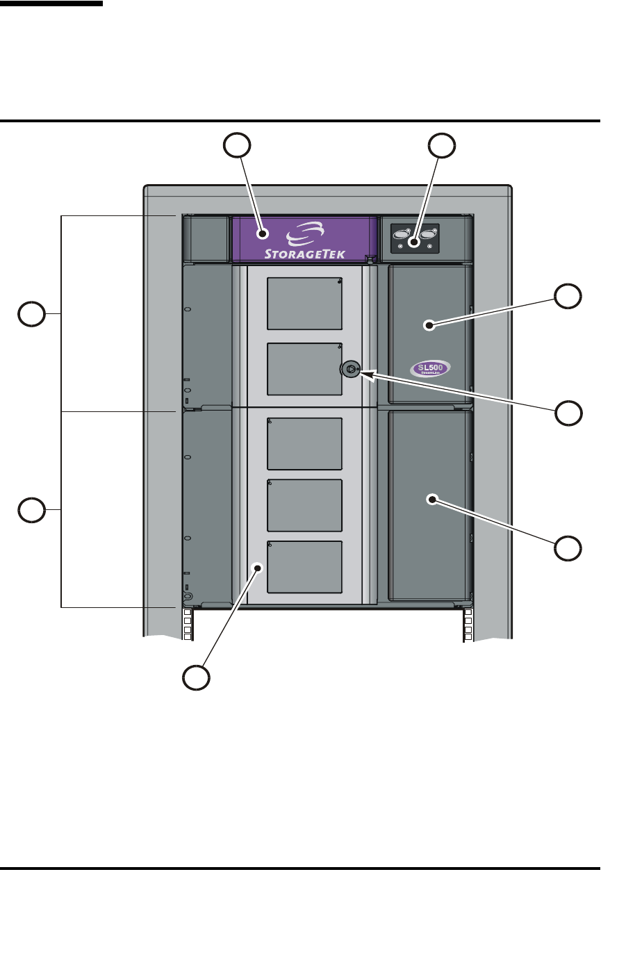
FIGURE 1-1 Front View of Library Components
1. Base module
2. Drive expansion module
3. Library door
4. Drive expansion module cartridge access port (CAP)
5. Library door lock
6. Base unit cartridge access port (CAP)
7. Keypad assembly
8. Robotics unit
Door CAP
L204_001
1
2
3
4
6
7
8
5
Views and Locations
96116 • Revision: KA Chapter 1 SL500 Introduction 3
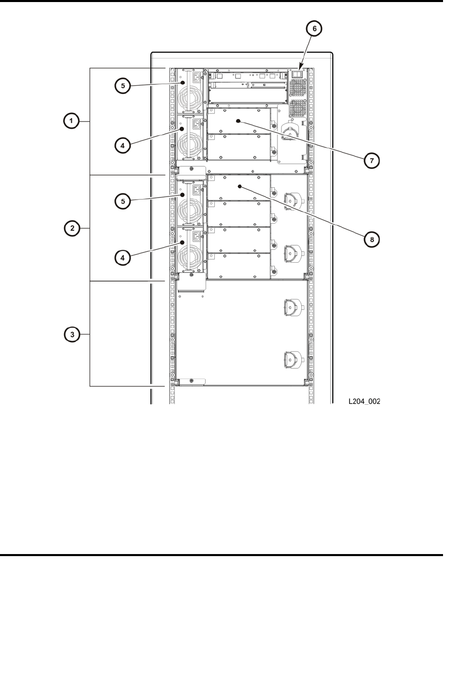
FIGURE 1-2 Back View of Library Components
1. Base module 4. Standard power supply (see note 1)
2. Drive expansion module 5. Library power switch
3. Cartridge expansion module 6. Tape drive 1 in base unit (see note 2)
4. Redundant power supply (see note 1) 7. Tape drive 1 in expansion module (see note
3)
Notes
1. If you are ordered only one power supply in a module, it should be installed in the top
location.
2. The host firmware sees tape drive 1; the SCSI firmware sees tape drive 0119.
3. The host firmware sees tape drive 1; the SCSI firmware sees tape drive 0219.

Library with LTO Storage Cells
4SL500 User’s Guide • July 2008 Revision: KA • 96116
Library with LTO Storage Cells
LTO Library Configurations
Caution – Firmware problems: You can not mix LTO and mixed-media arrays and
arrays within the same library. If you add expansion modules, the new modules must
have the same type arrays as the existing modules.
For each library:
■The Base Module contains the robotics unit and the base unit:
■The robotics unit has the robotic components and the keypad
■The base unit has up to 50 storage cells (see note), one or two tape drives, and a
five-cell cartridge access port (CAP).
Note – Only 30 of those storage cells can be used unless the cartridge upgrade
conversion bill has been installed, allowing the other 20 storage cells to be used. With
no upgrade, the first 30 storage cells after the reserved cells can be used for cartridge
storage. If the reserved storage cells are configured for storage, the numbering starts
there. The CAP cells also can be configured as storage cells.
■Drive expansion modules and Cartridge Expansion Modules can be added to a
standard rack to accommodate various storage cell and tape drive configurations.
Note – You must have a 50-cartridge capacity base unit, either from the initial order or
with the upgrade conversion bill, before you can order an expansion module.
See Appendix A, “SL500 Wall Diagrams and Specifications” for detailed diagrams and
dimensions.
LTO Library Internal Addressing
The numbering scheme uses the library, module, row and column scheme. Four
integers are used to represent the cartridge and tape drive slots, as viewed from the
front of the library.
1. Library number (always 0)
2. Library module number 1 (top of rack) through 5 (bottom of rack)
3. Row number 1 through 9 (Base Module) or 1 through 12 (expansion module)
4. Column number 1 through 9 for Base Module and Drive Expansion Module, 1
through 11 for Cartridge Expansion Module See “LTO Storage Cell and Drive
Capacities” on page 5 for more information.
Library with LTO Storage Cells
96116 • Revision: KA Chapter 1 SL500 Introduction 5
LTO Storage Cell and Drive Capacities
Note – Your software might conflict with the following information. Refer to your
software publication for unique information.
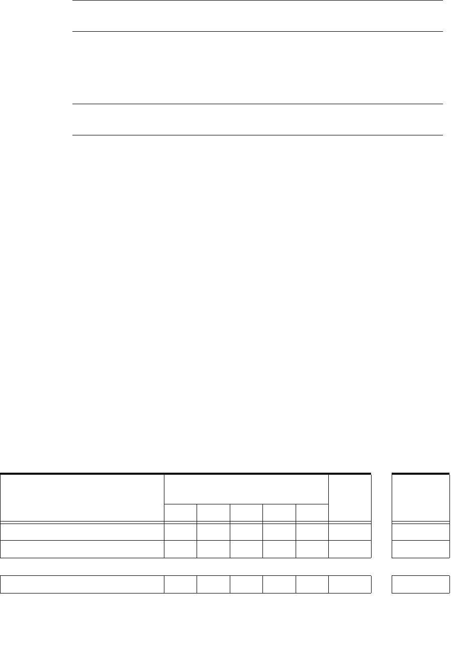
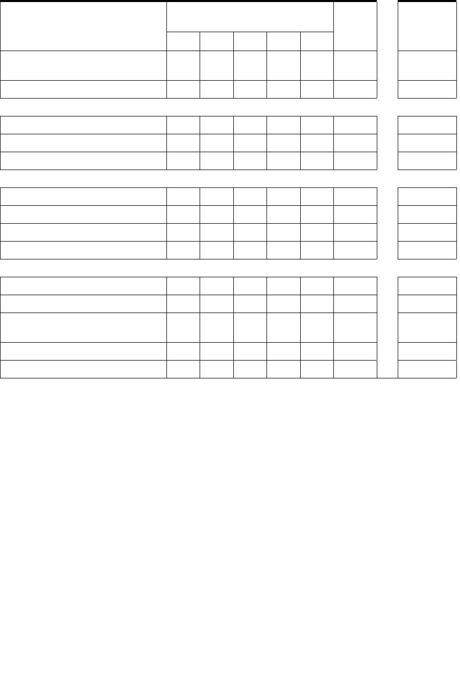
TABLE 1-1 shows the number of cartridge and tape drive slots available depending on
the type and number of modules installed. The table assumes that, when DEMs and
CEMs are installed in the same library, the DEMs are above all of the CEMs, as
preferred.
Note – Do not install an EZ DEM below an original CEM. This is not physically
allowed.
The following notes are factors that influence capacity:
1. When you add an expansion module below an existing module, you increase the
capacity of the module directly above it by:
■Base module: +16 storage cells
■CEM (when another CEM is below it): +10 storage cells
■DEM: +7 storage cells
2. When a CEM is installed below a Base Module or DEM, the top two rows on
columns 9, 10, and 11 of the CEM are not accessible (-6 storage cells because the tape
drives prevent the hand from reaching the cells).
3. The lowest module in the rack requires installation of the floor. The floor limits the
distance the robot can travel, which makes the bottom row(s) in the lowest module
inaccessible:
■Base module: -16 storage cells
■DEM: -7 storage cells
■CEM (below another CEM): -16 storage cells (-10 storage cells on the lowest CEM,
-6 storage cells on the CEM above it)
■CEM (below Base Module or DEM): -16 storage cells
4. Cartridge access ports:
■Base module: 5 storage cells (one magazine)
■Each DEM: 10 storage cells (two magazines)
■Each CEM: 10 storage cells (two magazines)
TABLE 1-1 LTO Storage Cell and Tape Drive Capacities
Modules
Maximum Number of Tape
Drives CAP
Cells
Total # of
Storage
Cells 2 6 101418
Base module 30 5 35
20-cartridge upgrade key 50 5 55
Adding 1 expansion module
Base module plus 1 limited DEM 100 15 115
Library with LTO Storage Cells
6SL500 User’s Guide • July 2008 Revision: KA • 96116
Adding LTO Storage Cell Capacity
If your needs have increased, you can increase the storage cell capacity and the number
of tape drives in the library. TABLE 1-1 lists how many storage cells and tape drives
can be gained by adding each Drive Expansion Module. The expansion modules are
installed into the same rack as the existing modules.
You can also add a redundant power supply. Contact your marketing representative.
Base module plus 1 full DEM
(with 50-cartridge upgrade key)
143 15 158
Base module plus 1 CEM 170 15 185
Adding 2 expansion modules
Base module plus 2 DEMs 227 25 252
Base module plus 1 DEM, 1 CEM 254 25 279
Base module plus 2 CEMs 290 25 315
Adding 3 expansion modules
Base module plus 3 DEMs 311 35 346
Base module plus 2 DEMs, 1 CEM 338 35 373
Base module plus 1 DEM, 2 CEMs 374 35 409
Base module plus 3 CEM 410 35 445
Adding 4 expansion modules
Base module plus 4 DEMs 395 45 440
Base module plus 3 DEMs, 1 CEM 422 45 467
Base module plus 2 DEMs, 2
CEMs
458 45 503
Base module plus 1 DEM, 3 CEMs 494 45 539
Base module plus 4 CEMs 530 45 575
TABLE 1-1 LTO Storage Cell and Tape Drive Capacities
Modules
Maximum Number of Tape
Drives CAP
Cells
Total # of
Storage
Cells 2 6 101418

Library with Mixed-Media Storage Cells
96116 • Revision: KA Chapter 1 SL500 Introduction 7
Library with Mixed-Media Storage Cells
Mixed-Media Library Configurations
Caution – Firmware problems: You can not mix LTO and mixed-media arrays and
magazines within the same library. If you add expansion modules, the new modules
must have the same type arrays as the existing modules.
Note – Your robotics unit must be part number 314558705 or higher to read SDLT
cartridge labels.
For each library:
■The Base Module contains the robotics unit and the base unit:
■The robotics unit has the robotic components and the keypad
■The base unit has up to 42 storage cells (see note), one or two tape drives, and a
four-cell cartridge access port (CAP).
Note – The base unit can be ordered originally as a 24- or 42-cell unit. If you received
the 24-cell version, only 24 of those storage cells can be used unless the upgrade
conversion bill has been installed. Without a conversion bill, the first 24 cells after the
reserved cells can be used for cartridge storage. If the reserved cells are configured for
storage, the numbering starts with the first physical cell on the left.
An upgrade conversion bill allows the other 18 storage cells in the base unit to be
used, for a total of 42. This conversion bill is for customers who want only the base
unit and do not expect to order an expansion module.
The CAP cells can also be configured as storage cells.
■Drive expansion modules (DEMs) and Cartridge Expansion Modules (CEMs) can be
added to a standard rack to accommodate various storage cell and tape drive
configurations.
Note – You must have a 42-cartridge capacity base unit before you can order an
expansion module.
See Appendix A, “SL500 Wall Diagrams and Specifications” for detailed diagrams and
dimensions.
Mixed-Media Library Internal Addressing
The numbering scheme uses the library, module, row and column scheme. Four
integers are used to represent the cartridge and tape drive slots, as viewed from the
front of the library.

Library with Mixed-Media Storage Cells
8SL500 User’s Guide • July 2008 Revision: KA • 96116
1. Library number (always 0)
2. Library module number 1 (top of rack) through 5 (bottom of rack)
3. Row number 1 through 8 (Base Module) or 1 through 10 (expansion module)
4. Column number 1 through 9 for Base Module and Drive Expansion Module, 1
through 11 for Cartridge Expansion Module
See “Mixed-Media Storage Cell and Drive Capacities” on page 8 for more information.
Mixed-Media Storage Cell and Drive Capacities
Note – Your software might conflict with the following information. Refer to your
software publication for unique information.
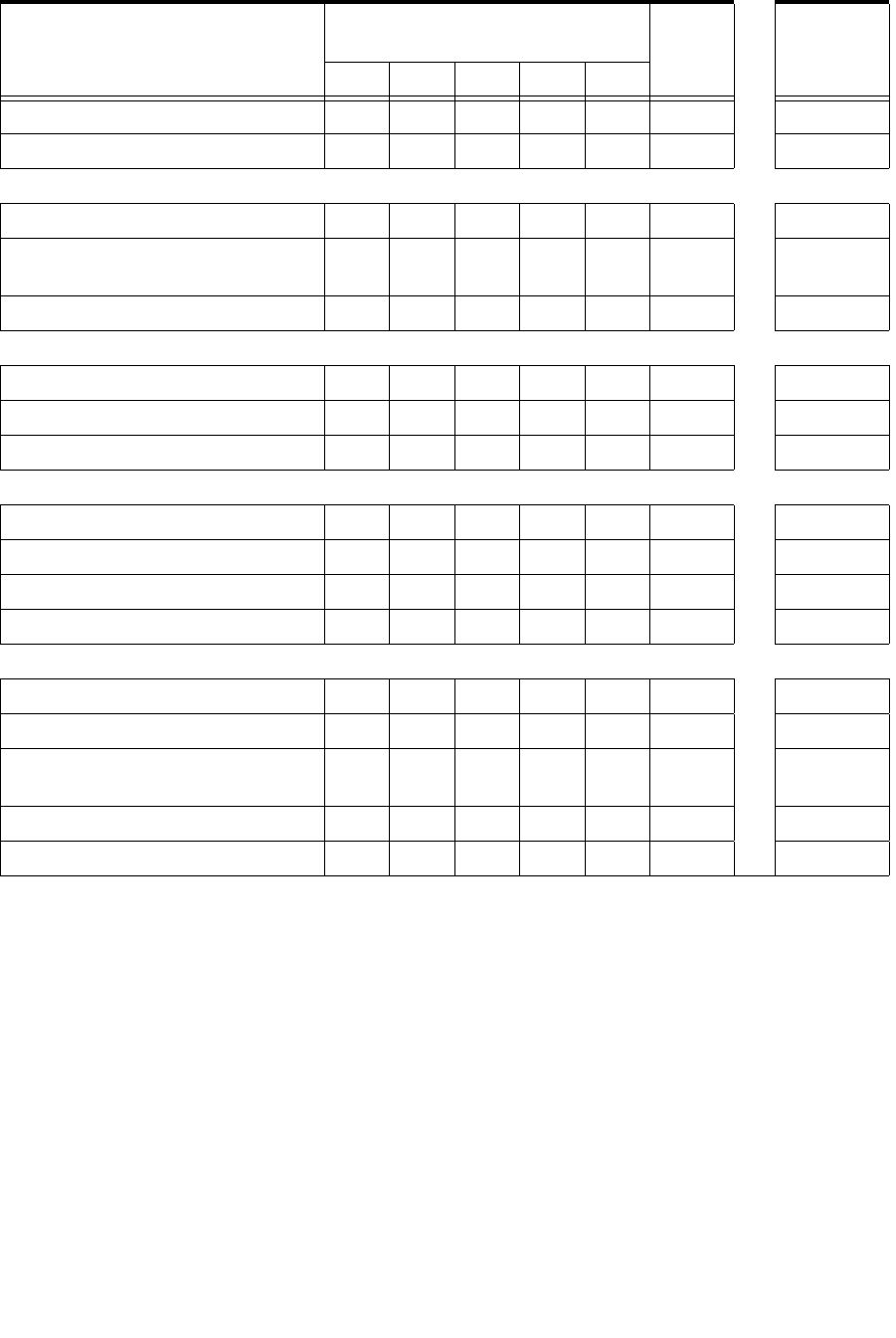
TABLE 1-2 shows the number of cartridge and tape drive slots available depending on
the type and number of modules installed. The table assumes that, when DEMs and
CEMs are installed in the same library, the DEMs are above all of the CEMs, as
preferred.
Note – Do not install an EZ DEM below an original CEM. This is not physically
allowed.
Note – The following notes are factors that influence capacity:
1. When you add an expansion module below an existing module, you increase the
capacity of the module directly above it by:
■Base module: +14 storage cells
■CEM (when another CEM is below it): +10 storage cells
■DEM: +7 storage cells
2. When a CEM is installed below a Base Module or DEM, the top two rows on
columns 9, 10, and 11 of the CEM are not accessible (-6 storage cells because the tape
drives prevent the hand from reaching the storage cells).
3. The lowest module in the rack requires installation of the floor. The floor limits the
distance the robot can travel, which makes the bottom row(s) in the lowest module
inaccessible:
■Base module: -14 storage cells
■DEM: -7 storage cells
■CEM (below another CEM): -16 storage cells (-10 storage cells on the lowest CEM,
-6 storage cells on the CEM above it)
■CEM (below Base Module or DEM): -16 storage cells
4. Cartridge access ports:
■Base module: 4 storage cells (one magazine)
■Each DEM: 8 storage cells (two magazines)
■Each CEM: 8 storage cells (two magazines)
Library with Mixed-Media Storage Cells
96116 • Revision: KA Chapter 1 SL500 Introduction 9
Adding Mixed-Media Storage Cell Capacity
If your needs have increased, you can increase the storage cell capacity and the number
of tape drives in the library. TABLE 1-2 lists how many storage cells and tape drives
can be gained by adding each Drive Expansion Module. The expansion modules are
installed into the same rack as the existing modules.
You can also add a redundant power supply. Contact your marketing representative.
TABLE 1-2 Mixed-Media Storage Cell and Tape Drive Capacities
Modules
Maximum Number of Tape
Drives CAP
Cells
Total # of
Storage
Cells 2 6 101418
Base module 24 4 28
18-cartridge upgrade 42 4 46
Adding 1 expansion module
Base module plus 1 limited DEM 86 12 98
Base module plus 1 full DEM
(with 33-cartridge upgrade)
119 12 131
Base module plus 1 CEM 140 12 152
Adding 2 expansion modules
Base module plus 2 DEMs 189 20 209
Base module plus 1 DEM, 1 CEM 210 20 230
Base module plus 2 CEMs 240 20 260
Adding 3 expansion modules
Base module plus 3 DEMs 259 28 287
Base module plus 2 DEMs, 1 CEM 280 28 308
Base module plus 1 DEM, 2 CEMs 310 28 338
Base module plus 3 CEM 340 28 368
Adding 4 expansion modules
Base module plus 4 DEMs 329 36 365
Base module plus 3 DEMs, 1 CEM 350 36 386
Base module plus 2 DEMs, 2
CEMs
380 36 416
Base module plus 1 DEM, 3 CEMs 410 36 446
Base module plus 4 CEMs 440 36 476

Controls and Indicators
10 SL500 User’s Guide • July 2008 Revision: KA • 96116
Controls and Indicators
Note – This section describes the controls and indicators that you can use to monitor
and troubleshoot the library. For tape drive controls and indicators, refer to the vendor
publications and Web sites. For details on the Local Operator Panel, see the SL500 Local
Operator Panel Guide, p/n 96258.
Power Switch
When the switch (see FIGURE 1-2) is in the On position (1) the library and tape drives
are powered-on. When the switch is in the Off position (0), the library and tape drives
are powered-off.
Note – Earlier built libraries had power supplies that had individual power switches.
Later libraries have one power switch that controls all power supplies in the rack.
Power Supply LED
The following table describes the power supply LED.
Drive Tray LED
The following table describes the drive tray LED.
TABLE 1-3 Power Supply LED
Activity Meaning Action
On Power supply is active. Nothing, this is normal.
Off The power supply failed. The service representative might need
to replace the power supply.
The power supply is not receiving
power.
The service representative might need
to check the connections and voltages.
TABLE 1-4 Drive Tray LED
Activity Meaning Action
On solid The drive fan failed, the temperature is
too high.
The service representative might need
to replace the fan.

Controls and Indicators
96116 • Revision: KA Chapter 1 SL500 Introduction 11
Keypad
The keypad is used to:
■Open the door
■Open all CAPs
■Notify you if service is required
Under normal conditions, at power-on, all keypad LEDs are solidly lit. Once library
applications begin:
1. All keypad LEDs turn off.
2. The Library Active LED flashes until the audit is complete, then turns off.
3. The Library Active LED turns on at the start of each command, then turns off when
each command is completed.
4. The Library Active LED flashes when the library is active.
Controls and Indicators
12 SL500 User’s Guide • July 2008 Revision: KA • 96116
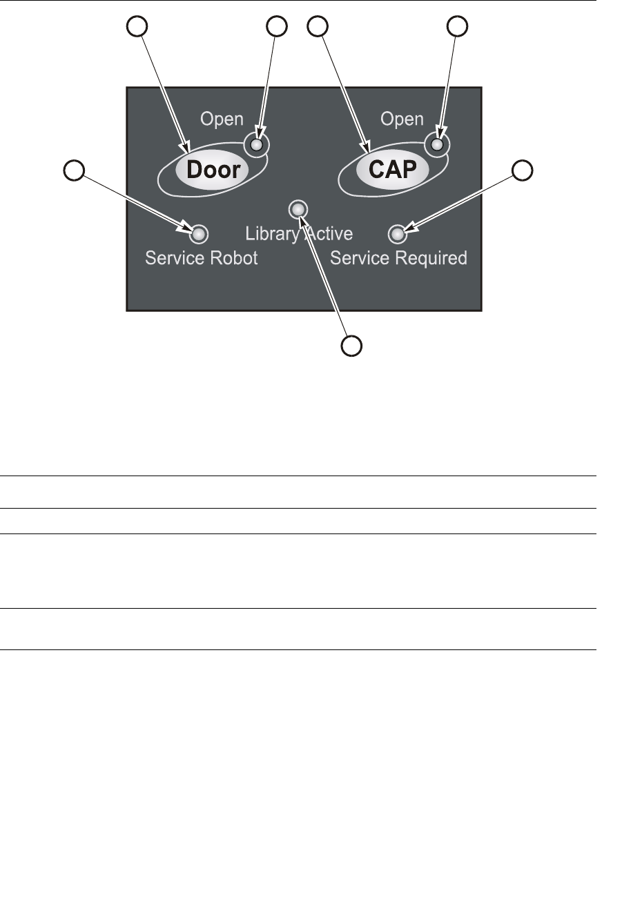
FIGURE 1-3 Buttons and Indicators
1. Door Open button 5. Service Required LED
2. Door Open LED 6. Library Active LED
3. CAP Open button 7. Service Robot LED
4. CAP Open LED
TABLE 1-5 Keypad Buttons and Indicators
Buttons/Indicator Description
Service Robot Indicator
LED is lit when the robot is not functioning.
The service representative might need to check the log_error
file for the result code and perform the appropriate action.
Library Active Indicator
LED is active when the library is active.
1324
57
6
L204
_
014

Controls and Indicators
96116 • Revision: KA Chapter 1 SL500 Introduction 13
Service Required
See TABLE 1-6 for details.
Indicator
■LED is normally not lit.
■LED is lit when the library experiences a failure or is in a
non-ready state.
Open Door Indicator
■LED flashes amber when the Open Door button is pressed.
■LED is solid amber when the robot is parked in the robotics
unit.
■LED flashes during initialization and audit.
■LED is not lit when the library is ready for customer use.
Button
When pressed:
1. Software allows the current job to complete. This could take a
while.
2. Software retracts the robot into the robotics unit so that it will
not be damaged when you open the door with the key.
Open CAP Indicator
■LED is amber when any CAP doors are open.
■LED is not lit when all CAP doors are shut.
Button
Button is used to open all CAP doors in a rack.
TABLE 1-6 Keypad Service Required LED
Activity Meaning Action
Flashing The redundant component failed. The service representative might need to
replace the failed redundant component,
such as power supply, tape drive, or
fan.
Diagnostics are running. Nothing, this is normal.
Diagnostics failed. The service representative might need to
check the log_error file for the result
code and perform the appropriate
action.
Door is open. Close and lock the door.
On solid The non-redundant component failed.
This includes the last working
component of a redundant set of
components, such as tape drives.
The service representative might need to
check the log_error and
log_warning files to determine which
component failed, and replace the failed
component.
The library has stopped operating. The service representative might need to
check the log_error file for the result
code and perform the appropriate
action.
TABLE 1-5 Keypad Buttons and Indicators (Continued)
Buttons/Indicator Description

Controls and Indicators
14 SL500 User’s Guide • July 2008 Revision: KA • 96116
RLC Card Indicators
The following table describes the RLC card indicators.
TABLE 1-7 RLC Card Indicators
Indicator Description
EJECT OK Indicator
LED is solid blue when the RLC card can be removed (Currently, only one
RLC card is available.).
FAULT Indicator
LED flashes red when the controller has detected a problem.
STANDBY Indicator
LED is yellow when the RLC card is not the active card (Currently, only one
RLC card is available.).
ACTIVE Indicator
LED is solid green when the RLC card is the active card (Currently, only one
RLC card is available.).

Tape Drives and Cartridges
96116 • Revision: KA Chapter 1 SL500 Introduction 15
Tape Drives and Cartridges
The library supports:
■Linear Tape-Open (LTO) Ultrium tape drives:
■Hewlett-Packard LTO Gen 2, 3 and 4 (check availability for Gen 4) SCSI low
voltage differential (LVD) and Fibre Channel (FC)
■IBM LTO Gen 2, 3 and 4 (check availability for Gen 4) SCSI LVD and FC
■Quantum SDLT tape drives:
■SDLT 320 SCSI LVD
■SDLT 600 SCSI LVD and FC
■DLT-S4 SCSI and FC
Tape drives are hot-swappable. This means they can be replaced without removing
power from the library, as longer as the following actions are done:
■Back up the server before removing the tape drive.
■If the tape drives are daisy-chained, stop all data processing on the channel to which
the tape drives are connected before disconnecting the tape drives.
■Make sure that there is no activity on the SCSI bus before disconnecting the external
SCSI cables. Stop all processes on the host.
■Make sure that all signals are terminated at each end of the SCSI bus.
■If your external SCSI cables are long enough that they do not interfere with
removing and replacing the tape drives, you can swap tape drives without
disconnecting the external SCSI cables. If so, disregard the steps to remove those
cables.
Caution – Possible data loss or system problem: If you must disconnect the external SCSI
cables, make sure that you quiesce the system first (stop all processes on the tape drives
on the SCSI bus with the tape drive you are replacing).
All tape drives are mounted on SL500-unique tray assemblies. Each assembly contains
the:
■Tape drive
■+5 VDC fan
■RLD tape drive interface card
Drive tray assemblies are installed in slots (also called bays), accessible from the back of
the library. When a tape drive is inserted into the assigned slot, it connects to the RLD
card by way of a cable. The RLD card connects directly to the RLM or RLE (Drive
Expansion Module) backplane through a blind-mate connector.
Note – If a slot does not contain a tape drive, a vacancy plate must be installed over
the slot.

Tape Drives and Cartridges
16 SL500 User’s Guide • July 2008 Revision: KA • 96116
LTO Tape Drives and Cartridges
Note – LTO technology was developed by IBM, Hewlett-Packard, and Seagate. LTO is
an “open format’ technology, which means that users have multiple sources of product
and media.
This section discusses media compatibility and cartridge labels. For all other tape drive
and media information, such as specifications, refer to:
■The specific vender Web site
■http://www.sun.com/storagetek/index.jsp
For best results, match the cartridges with the specific drive type (for example, use
LTO 2 cartridges in Gen 2 drives):
The following table lists the compatibility issues among the various LTO cartridges and
tape drives. Although SL500 does not support Gen 1 drives, the column is listed for you
to consider if you need to migrate your data from older types of cartridges to newer
ones.
Note – LTO 3 drives can accept 400 GB WORM (Write Once Read Many) cartridges.
LTO 4 drives can also accept these plus the 800 GB WORM cartridges.
TABLE 1-8 LTO Media/Tape Drive Compatibility
Media Label Gen 1 Drive Gen 2 Drive Gen 3 Drive Gen 4* Drive
LTO 1 L1 Read and write Read and write Read only Non
applicable
LTO 2 L2 Non applicable Read and write Read and
write
Read only
LTO 3 L3 Non applicable Non applicable Read and
write
Read and
write
LTO 4 L4 Non applicable Non applicable Non
applicable
Read and
write
WORM
(400 GB)
LT Non applicable Non applicable Read and
write
Read and
write
WORM
(800 GB)
LU Non applicable Non applicable Non
applicable
Read and
write
Note: When available. LTO 4 drives are supported with library firmware 1126 and later.

Tape Drives and Cartridges
96116 • Revision: KA Chapter 1 SL500 Introduction 17
SDLT/DLT-S4 Tape Drives and Cartridges
Note – Your robotics unit must be part number 314558705 or higher to read
SDLT/DLT-S4 cartridge labels.
This section discusses media compatibility and cartridge labels. For all other tape drive
and media information, such as specifications, refer to:
■The specific vender Web site
■http://www.sun.com/storagetek/index.jsp
For best results:
■Use Super DLT tape 1 cartridges in SDLT 320 tape drives
■Use Super DLT tape 2 cartridges in SDLT 600 tape drives
■Use DLT tape S4 cartridges in DLT-S4 tape drives
The following table lists the compatibility issues among the various SDLT cartridges
and tape drives. Consider the information if you need to migrate your data from older
types of cartridges to newer ones.
Note – SDLT600 and DLT-S4 tape drives with appropriate firmware can accept
cartridges with the WORM feature.
The WORM (write once read many times) feature prevents the user from altering or
erasing information from the tape. For more information, go to the Quantum Web site
and do a search on DLTICETM.
Note – The WORM feature cartridge must be:
■unformatted native
■blank native
■native with one filemark and an EOD
See “Cartridge Information” on page 347 for more specific information about
cartridges.
TABLE 1-9 SDLT/DLT-S4 Media/Tape Drive Compatibility
Media SDLT 320 Drive SDLT 600 Drive DLT-S4* Drive
SDLT 1 media Read and write Read only Read only
SDLT 2 media No action Read and write Read only
DLTIV media Read only No action No action
DLT tape S4 No action No action Read and write
Note: DLT-S4 drives are supported with library firmware 1126 and later.
Cartridge Access Ports
18 SL500 User’s Guide • July 2008 Revision: KA • 96116
Cartridge Access Ports
The cartridge access ports (CAPs) can be used to add cartridges to the library, or
remove cartridges from the library without interrupting normal robotic operation.
■The CAP in the Base Module has one five-cell magazine.
■The CAP in the Drive Expansion Module has two five-cell magazines.
Although the CAPs are not physically connected, they are logically connected. If any of
the CAPs are open, the CAP LED on the keypad will be on, alerting the operator to take
action to close the CAP. If all of the CAPs are closed, the CAP LED will be off.
You can use the keypad on the robotics unit to issue a command for the robot to unlock
the CAP.
The CAP has two settings, ALLOW and PREVENT. ALLOW is the default setting after
you power-on or reset the library. The following table shows how these settings affect
the CAPs. For CAP LED indicator information see “Controls and Indicators” on
page 35.
CAP Condition ALLOW PREVENT
All of the CAPs are closed When you press the CAP button
all of the CAPs in the rack will
open.
The library firmware turns on
the CAP LED.
When you press the CAP
button, the action is ignored and
all of the CAPs remain closed.
Any of the CAPs are open When you press the CAP
button, any CAP that is not
open in the rack will open.
When you press the CAP
button, the action is ignored and
all of the CAPs remain in their
individual current state of open
or closed.

Robotics Unit
96116 • Revision: KA Chapter 1 SL500 Introduction 19
Robotics Unit
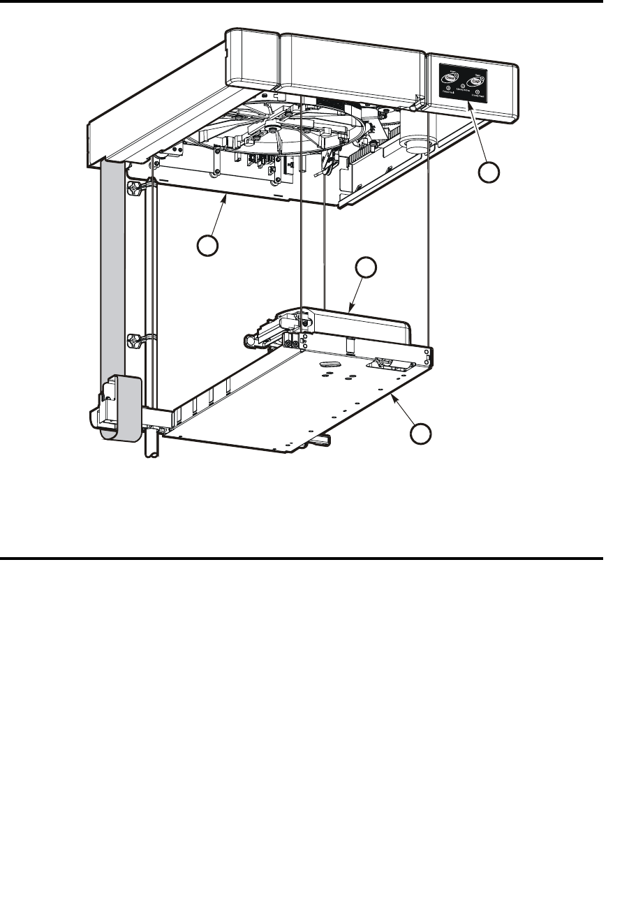
The robotics unit provides movement of cartridges among the storage cells, tape drives,
and cartridge access ports (CAPs). The three main robotic components are, as shown in
FIGURE 1-4:
■Z drive assembly
■X table assembly
■Hand assembly
The Z drive assembly uses the Z drive pulley to move the X table up and down to the
desired storage cell or tape drive. At the same time, the X carriage assembly (containing
the hand) moves the hand forward and backward; the wrist motor rotates the hand
right and left.
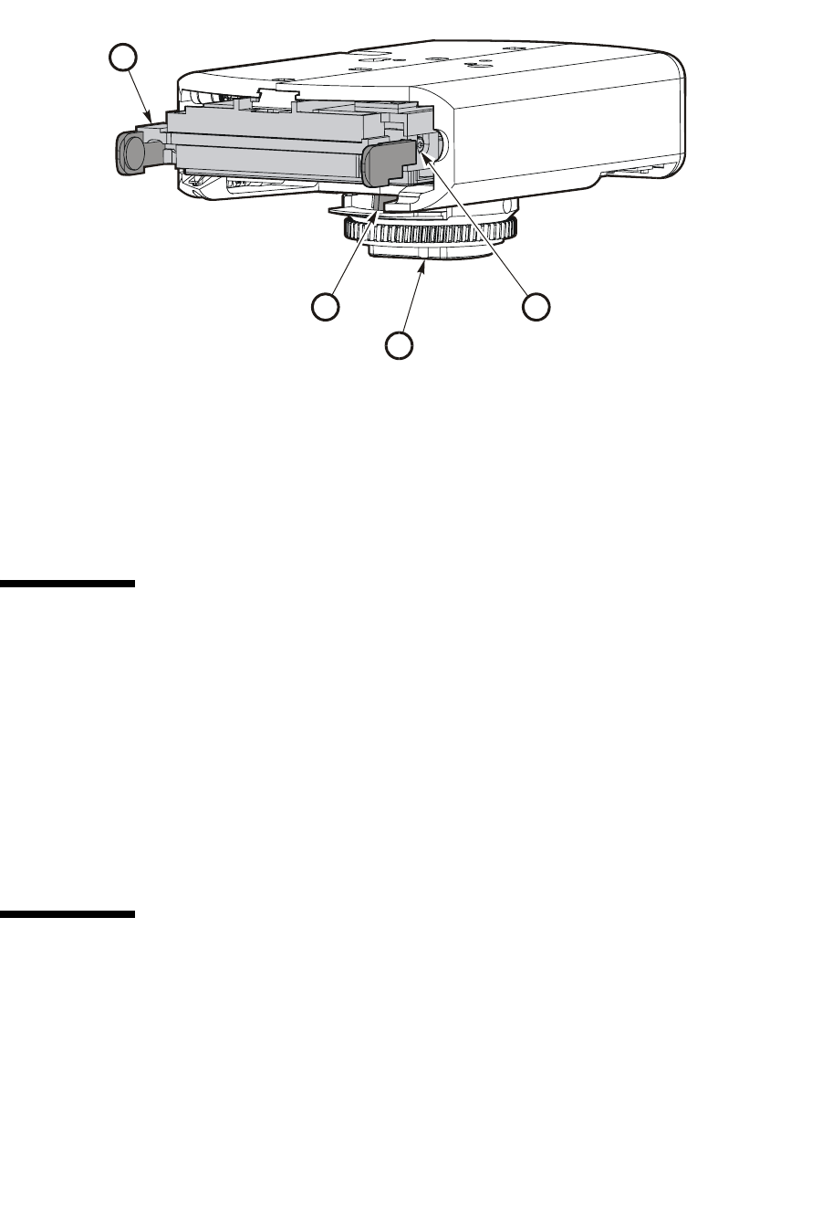
The hand assembly contains the wrist hub assembly, gripper assembly, and bar-code
scanner. The gripper assembly has fingers that grasp the sides of the cartridge. If the
library loses power while a cartridge is between the fingers, the manual release screw is
used to remove the cartridge. A worm gear can be used to rotate the hand to the correct
position to access the manual release screw.
For safety purposes, the robotics will be “parked” in the robotics unit when the front
door is opened or when the Open Door button is pressed on the keypad. Parked means
that the robotics components are fully retracted into the robotics unit at the top of the
library. To verify the robot is parked, look at the lever in the cutout beneath the facade
and to the bottom left of the keypad, the lever should be to the left.
Robotics Unit
20 SL500 User’s Guide • July 2008 Revision: KA • 96116
The robotics unit is accessible from the front of the rack.
.
FIGURE 1-4 Robotics Components
1. Z drive assembly
2. Hand assembly
3. Keypad assembly
4. X table assembly
L204_011
1
4
2
3
Power System
96116 • Revision: KA Chapter 1 SL500 Introduction 21
Power System
The base unit has one standard power supply. A second supply can be ordered and
installed to provide redundant power to the module components. Each supply should
be plugged into a separate circuit and powered-on to provide redundant power. If one
supply fails, the second supply automatically provides power.
A single power switch on the back of the library is used to power-on or power-off all
the power supplies in the rack:
■The ON position is 1.
■The OFF position is 0.
Cooling
The fans provide cooling for the library electronics. The tape drives and power supplies
contain their own fans.
FIGURE 1-5 Hand Assembly
1. Gripper
2. Bar-code scanner
3. Wrist hub
4. Finger release screw
L204_024
1
42
3

Electronics
22 SL500 User’s Guide • July 2008 Revision: KA • 96116
Electronics
The electronics consist of the control path and robotic cards in the base unit.
Communications include:
■Command line interface (CLI) over an RS232 port
■Public Ethernet port (The private port is for future use)
■Point to point library/tape drive RS423 interface
■Control path card for LVD SCSI or SCSI over Fibre Channel
Sensors include:
■Card temperature
■Fan operational
■Power safe
■Tape drive present
■Tape drive fault LED
RLC Card
The RLC card is the processor card. It contains all the necessary hardware to maintain
the robotics, interfaces, servo and vision control, and the door/CAP sensor status.
The card stores the library capacity information and the volume serial numbers (also
called VOLID) of the cartridges in the library storage cells.
Interface Cards
The RLW card is the LVD SCSI interface card. The MPU2 card is the Fibre Channel
interface card.

Safety Features
96116 • Revision: KA Chapter 1 SL500 Introduction 23
Safety Features
The following subsections describe the safety features that are incorporated into the
library.
Cards and Power Supply
The RLC card, SCSI (MPW/RLW) or Fibre Channel (MPU2) interface card, and the
power supply are housed inside protective modules to prevent you from coming into
contact with hazardous voltages and sensitive electronics.
Robotics
The software parks the robot by retracting it into the robotics unit module before the
front door can be opened to prevent the robot from being damaged.
When the front door is opened, power is removed from the robot.
Front Door
The front door must be opened with a key to ensure that the data is secure. If the door
is not fully closed, a sensor relays the condition to the software and the robot remains
disabled.
Interfaces
24 SL500 User’s Guide • July 2008 Revision: KA • 96116
Interfaces
The major interfaces are:
■Library control path support for LVD SCSI or SCSI over Fibre Channel
■Data path for a single-port SCSI or dual-port Fibre Channel tape drive
■Cartridge access ports and sensors for indicating a door open or closed condition
■Front door opened button (on keypad), key for opening door, sensor LED that
indicates door is closed and latched.
■Public 100BaseT Ethernet Port for the StorageTek Library Console (SL Console) and
remote service access (see FIGURE 1-6 and “StorageTek Library Console” on
page 27).
Note – Currently, only one RLC card is available.
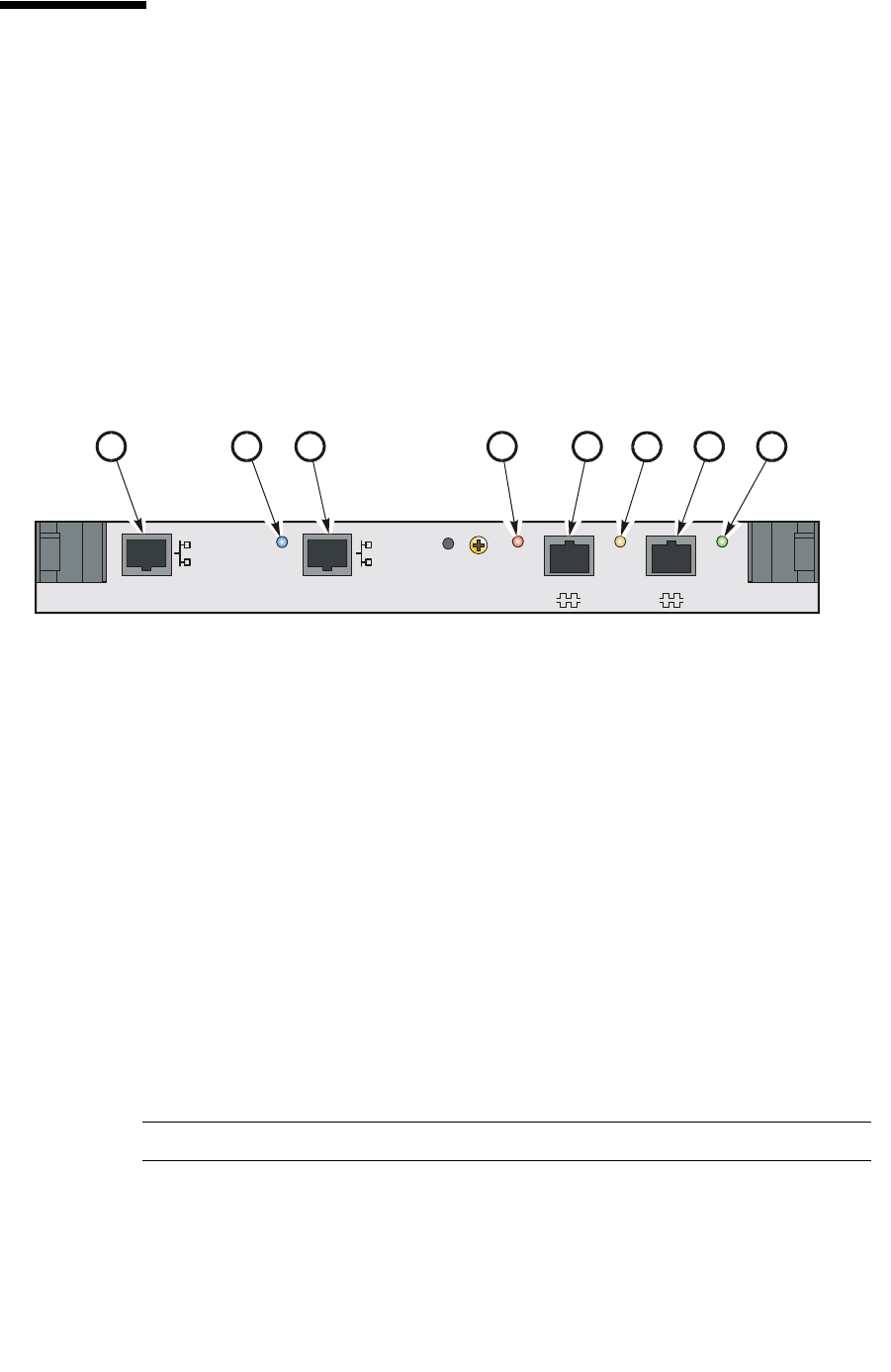
FIGURE 1-6 Library Interfaces Locations
1. Private Ethernet port is for future use.
2. Eject OK (hot-swappable) LED, when on, indicates that the RLC card can be removed. (See
note below.)
3. Public Ethernet port is for remote service access, SL Console, and SNMP (future)
4. Fault LED indicates that the controller has detected a problem.
5. Reserved for future use.
6. Standby LED, when lit, indicates the RLC card (when two RLC cards are installed) is in
standby mode.
(See note below.)
7. CLI port is an RJ-45 serial port for service representatives.
8. Active LED, when lit, indicates this RLC card is active if two RLC cards are installed. If only
one card is installed, the LED is always on. (See note below.)
PRIVATE PUBLIC RESERVED
CLI
EJECT
OK FAULT STANDBY ACTIVE
L204
_
008
123 45
678

Tape Management Software
96116 • Revision: KA Chapter 1 SL500 Introduction 25
Tape Management Software
The tape management software provides the instructions to perform tape read and
write operations and robotic move operations. When the library is in automated mode,
these operations occur without manual intervention. The software determines where
the cartridge is located by accessing audit data uploaded from the library. The software
then allocates the tape drive to receive the cartridge.
For command descriptions and instructions, refer to your software publications.

Tape Management Software
26 SL500 User’s Guide • July 2008 Revision: KA • 96116

96116 • Revision: KA 27
CHAPTER 2
StorageTek Library Console
Introduction
The StorageTek Library Console (SL Console) is a Java-based software application that
provides a graphical user interface (GUI) for monitoring and managing the StorageTek
library.
Following are some of the activities you can perform with the SL Console:
■Manage available library storage capacity
■Manage and configure library partitions (optional feature)
■View and modify status and properties of the library and associated devices (drives,
CAP, robots, and elevators)
■Perform an audit on all or part of the library
■Perform a self-test on the library or an associated device
■Perform a diagnostic move (exercise a robot)
■Locate a cartridge
■Move a cartridge from one location to another
■Display library event logs
■Display error explanations
■Download new library firmware while the library is in operation
■Display context-sensitive help
SL Console Modes
Depending on your needs, you can run the SL Console in any of the following modes.
For details and procedures, see:
■“Local Operator Panel” on page 33
■“Standalone SL Console” on page 35
■“Web-launched SL Console” on page 42

SL Console Security
28 SL500 User’s Guide • July 2008 Revision: KA • 96116
SL Console Security
Security features built into the SL Console control both user authentication and user
authorization. The security features include:
■User IDs – User IDs control user authentication. Each user must have a valid, active
user ID and password to log in to the SL Console.
■Access permissions – Access permissions control user authorization. Each user ID is
assigned a set of access permissions, which determine the types of requests the user
can submit through the SL Console. For example, in order to modify the system
properties of a drive, a user must log in with a user ID that has the proper access
permissions.
When you log in to the SL Console with a valid user ID, password, and library name,
the system authenticates your identity and then authorizes your access to the various
SL Console functions.
User IDs
To log in to the SL Console, you must have a valid, active user ID. Each user ID must be
assigned a password.
There are a fixed set of user IDs at a site. The user IDs include admin (customer
administrator), service (Sun Customer Services Engineer), and oem (third-party field
service technician). When you log in successfully, the SL Console displays your user ID
in the status bar of the screen.
Only one user at a time can be logged in to the local operator panel, but any number of
users can connect to a library through the standalone SL Console or Web-launched
SL Console.
Activation Password
Before any users at your site can use the SL Console for the first time, your library
administrator must activate the “admin” userid with a special activation password.
Your Sun support representative provides your administrator with the activation
password, which is valid for one-time use only.
After logging in with the activation password, the administrator must change the
admin user ID password to ensure system security.
For details about this process, see the appropriate library Installation Guide.

SL Console Usage Tasks
96116 • Revision: KA Chapter 2 StorageTek Library Console 29
SL Console Usage Tasks
■Log in to the SL Console
■Log Off the SL Console
■Change a User Password
▼ Log in to the SL Console
Login procedures depend on the SL Console mode being used. For detailed
instructions, see the following topics:
■“Log in to the Local Operator Panel” on page 34
■“Log in to the Standalone SL Console” on page 41
■“Log in to the Web-launched SL Console Using a Browser or Command Line” on
page 43
■“Log in to the Web-launched SL Console Using an Icon” on page 49
▼ Log Off the SL Console
Note – Before you log off, make sure all operations for the current SL Console session
have completed (for example, code loads, audits, diagnostic moves).
1. From any SL Console screen, select Tools > Log Off.
2. In the Confirm popup, do one of the following:
■Click Cancel to remain logged in to the SL Console.
■Click OK to terminate the current SL Console session.
The Login screen appears.
3. Click Exit to close the SL Console.
▼ Change a User Password
1. Select Tools > User Mgmt.
2. On the User tree, expand the Permanent folder.
3. Click the user account you want to modify.
4. Complete the following fields: Current Password, New Password, and
Retype Password.
5. Click Modify.
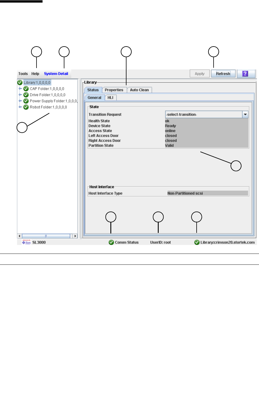
SL Console Screen Display
30 SL500 User’s Guide • July 2008 Revision: KA • 96116
SL Console Screen Display
The following figure and table explain the components of the SL Console screen.
Component Name Description
1 Menu bar—includes the
Tools Menu and the
Help Menu
Tools menu provides access to System Detail, Reports,
Monitors, Utilities, Partitioning, User Management, and
Log off functions.
Help menu provides access to the table of contents of the help
system. It also identifies the version of the SL Console in use.
2 Title bar Displays the title of the current screen.
3 Function tabs Identifies the available functions for a screen.
4 Options bar Location of buttons related to the screen (for example, Apply,
Refresh, Print). Always includes the SL Console Help button
(?). See “Synchronizing the Display With the Controller
Database” on page 31 for details on using the Apply and
Refresh buttons.
1 2 43
5
78 6
9

SL Console Screen Display
96116 • Revision: KA Chapter 2 StorageTek Library Console 31
Synchronizing the Display With the Controller
Database
When you first bring up an SL Console screen, the display reflects the most recently
saved data from the library controller database. If you use the screen to modify the
library contents or configuration, your changes do not update the controller database
until you commit your changes by clicking the Apply button. Multiple users can access
the library at the same time, using the SL Console, command line interface, and various
host applications to make their own changes to the library contents and configuration.
If other users make changes and apply them to the controller database, you will not see
these changes until you click Apply or Refresh on your screen. Therefore, the display
you see on the SL Console may not reflect the actual saved library configuration at a
given point in time.
For these reasons, if you are making major modifications to the library
configuration—adding modules, defining partitions, etc.—it is important that you
coordinate these changes with other library users. Failure to do so could result in
conflicts within the controller database.
5 Work area Location of the screen data.
6 Library health indicator Identifies the library to which the SL Console is connected,
and displays a graphical representation of the library health.
7 UserID indicator Displays the user ID currently logged in to the SL Console.
8Server communication
health indicator
Displays a graphical heartbeat monitor indicating the state of
server communication health.
9 Device tree Lists the devices included in the library.
Component Name Description

SL Console Screen Display
32 SL500 User’s Guide • July 2008 Revision: KA • 96116
Modifying the Screen Layout
Note – This feature is available starting with SL Console version FRS_3.30. It is
available on selected screens only.
You can modify the layout and display of selected SL Console screens as follows.
TABLE 2-1 Screen Display Modifications
Display Option Instructions
Sort the display by any
column
Click the heading of the column you want to sort by. Initially
the sort will be in ascending order. Click the heading again to
switch between ascending and descending order.
Arrange the columns in
any order
Click and drag a column heading horizontally to any position
in the heading row.
Resize the columns Click the border of the column heading and drag it left or
right to change the column width.

Local Operator Panel
96116 • Revision: KA Chapter 2 StorageTek Library Console 33
Local Operator Panel
The local operator panel is an optional feature of the library, which is built in to the
Base Module on the SL500. It enables you to run most of the SL Console application
directly at the library from a flat-screen display with a touch-screen interface.
The local operator panel has the following features:
■Flat-panel display, resident within the library (8-inch on the SL500)
■Touch-screen interface, allowing alphanumeric data entry; pen and stylus available
■No keyboard or mouse option
LEDs located directly below the local operator panel provide the following status
information:
■LIB ACTIVE—Library processor is working.
■WAIT—Library firmware is loading.
■SVC REQ—Library is rebooting.
▼ Enter Data Using the Keypad
1. Click on the keyboard icon associated with the desired field.
A popup containing a graphical keyboard and display area appears.
2. Click the graphical keys necessary to enter the desired data.
3. Click Enter to save your entry.
The popup is closed and the data is displayed in the associated field.
▼ Modify Data Using the Keypad
1. Use the navigational keys to position the cursor next to the characters to be modified.
The existing text remains on the display, but is changed to normal text.
2. Click the navigational, editing, and text keys to make the desired changes.
3. Click Enter to save the changes or Cancel to restore the original text to the field.

Local Operator Panel
34 SL500 User’s Guide • July 2008 Revision: KA • 96116
▼ Log in to the Local Operator Panel
Note – Only one user at a time can log in to the local operator panel.
Note – If the touch-screen panel is blank, touch the screen anywhere to activate the
Login screen.
1. Use the keypad to enter your login information (see “Enter Data Using the Keypad”
on page 33 for detailed instructions).
User ID: SLC_login
Password: password
where:
■SLC_login is the SL Console user ID.
■password is the password assigned to this user ID.
Note – The user ID you use determines the screens you can access. See “SL Console
Security” on page 28.
2. Click Log on.

Standalone SL Console
96116 • Revision: KA Chapter 2 StorageTek Library Console 35
Standalone SL Console
The standalone SL Console is a standard feature of the StorageTek library. It enables
you to run the SL Console application remotely from a PC or workstation that has a
network connection to the library. Using the standalone SL Console you can connect to
any library for which you have a valid user ID.
Security Considerations
The SL Console application interfaces with the primary library interface (PLI) over a
security software layer (SSL). The SSL provides a secure communication path between
the library and the customer’s operator panel; this prevents an unauthorized network
user from monitoring library activity.
Installation Requirements
You can install the standalone SL Console on a computer meeting the following
requirements:
The standalone SL Console software is available for download at the following Sun
Microsystems, Inc. sites:
Note – You must have a valid login ID and password for the download site you are
using. Contact your Sun support representative for assistance.
Platform Solaris 9—SPARC
Solaris 10—SPARC
Windows 2003 Server—32 bit
Windows XP Client—32 bit
Windows Vista—32 bit
Other Ethernet connection to the library
User Location Name URL
Sun Customers Sun Download Center http://www.sun.com/download/ind
ex.jsp
Sun Partners
and OEMs
Sun Partner Exchange https://spe.sun.com/spx/control
/Login

Standalone SL Console
36 SL500 User’s Guide • July 2008 Revision: KA • 96116
Standalone SL Console Installation
Note – Your StorageTek CSE may have performed these procedures for you during
library installation.
To install the standalone SL Console on your PC or workstation, you must use the
following procedures:
1. “Download and Initiate the Standalone SL Console Installer from the Sun Download
Site” on page 36.
2. “Install the Standalone SL Console” on page 36.
▼ Download and Initiate the Standalone SL Console Installer
from the Sun Download Site
Use this procedure to download the standalone SL Console installer program and
initiate it on your PC or workstation.
Note – You must have a valid login ID and password for the download site you are
using. Contact your Sun support representative for assistance.
1. Start a Web browser on your PC or workstation.
2. In the Address or Location Bar, enter the URL of the appropriate Sun download site.
See“Installation Requirements” on page 35 for details.
3. Log in to the Sun download site using your assigned login ID and password.
4. Navigate to the standalone SL Console installer file.
5. Select the SL Console code level you want.
6. Select the appropriate installer file for your platform:
■Microsoft Windows: SLConsoleWindowsSTK.exe
■Sun Solaris: SLConsoleSolarisSTK.bin
7. Save the file to your PC or workstation.
8. Double-click the SL Console installer file icon on your PC or workstation to start the
installation.
9. To complete the installation, see “Install the Standalone SL Console” on page 36.
▼ Install the Standalone SL Console
Use this procedure to install the standalone SL Console on your PC or workstation.
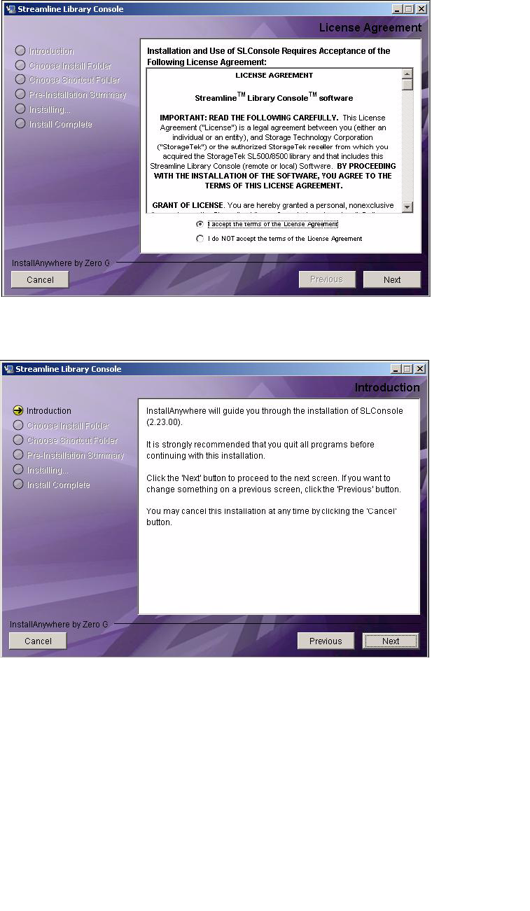
Standalone SL Console
96116 • Revision: KA Chapter 2 StorageTek Library Console 37
1. Start the installer program according to the instructions in “Download and Initiate the
Standalone SL Console Installer from the Sun Download Site” on page 36.
The License Agreement screen appears.
2. Review the information, and click I accept.
The Introduction screen appears.
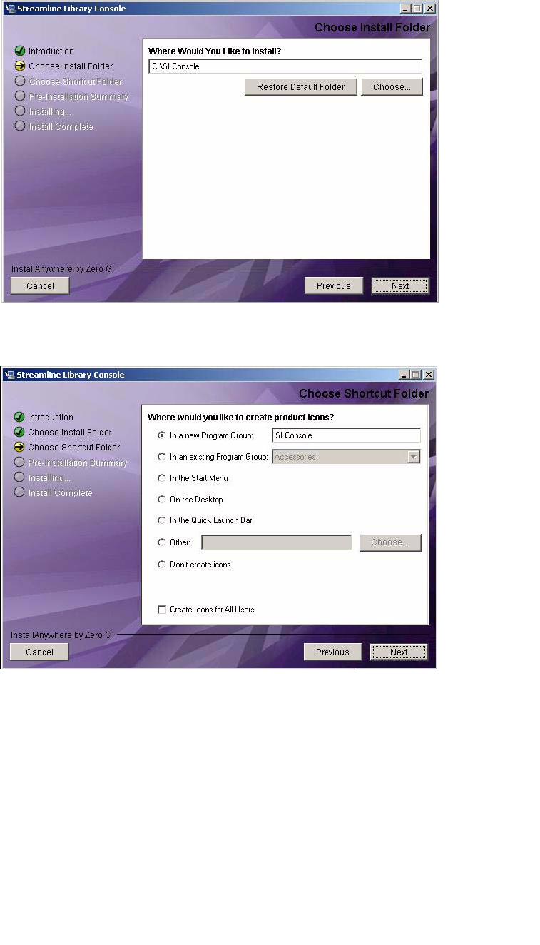
Standalone SL Console
38 SL500 User’s Guide • July 2008 Revision: KA • 96116
3. Review the information, and click Next.
The Choose Install Folder screen appears.
4. Enter the location where you want to install the file, and click Next.
The Choose Shortcut Folder screen appears.
5. Enter the location where you want to create the shortcut icon, and click Next.
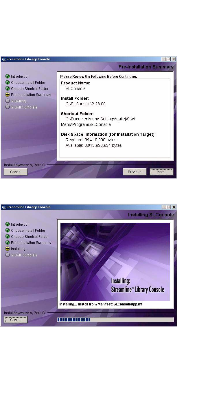
Standalone SL Console
96116 • Revision: KA Chapter 2 StorageTek Library Console 39
Note – On Solaris, the default location for shortcuts is the user’s home directory.
However, shortcuts cannot be created in /, which is the root user’s home, so if you are
installing on a Solaris platform as root you must choose something other than the
default location. In this case, it is recommended that you choose /usr/bin or a similar
location.
The Pre-Installation Summary screen appears.
6. Review the information, and click Install.
The installation begins, and the Installing SL Console screen appears.
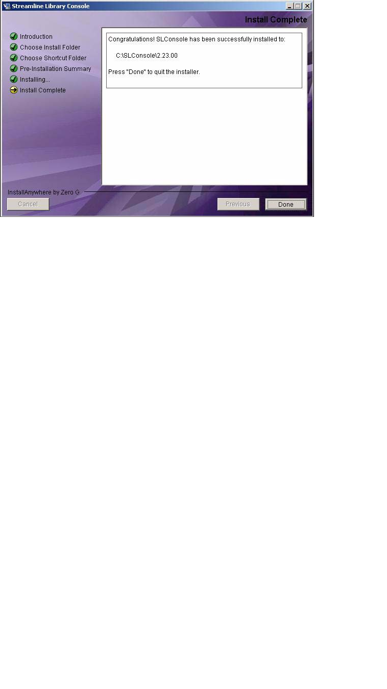
Standalone SL Console
40 SL500 User’s Guide • July 2008 Revision: KA • 96116
7. When the installation finishes, the Install Complete screen appears.
8. Review the information and click Done to exit the installation program.
Standalone SL Console
96116 • Revision: KA Chapter 2 StorageTek Library Console 41
▼ Log in to the Standalone SL Console
Note – Using the standalone SL Console you can connect to any library for which you
have a valid user ID.
1. Start the SL Console application on your PC or workstation by doing either of the
following:
■Double-click the SL Console icon on the desktop.
■Select Start > RunSLConsole or Launch > RunSLConsole
The SL Console starts and the Login screen appears.
2. Enter your login information.
User ID: SLC_login
Password: password
Library: library_ID
where:
■SLC_login is the SL Console user ID.
■password is the password assigned to this user ID.
■library_ID is the library to which you want to connect, expressed in either of the
following ways:
■IP address of the library, in dotted decimal notation (nnn.nnn.nnn.nnn)
■DNS alias of the library
Note – The user ID you use determines the screens you can access. See “SL Console
Security” on page 28.
3. Click Log on.
Standalone SL Console Updates
Note – Before you can install a new version of the standalone SL Console, you must
uninstall the previous version. See your PC or workstation documentation for detailed
instructions. Running multiple versions of the SL Console on the same PC or
workstation can cause problems such as inconsistent data on reports.
Once you have uninstalled the previous version of the SL Console, see “Standalone
SL Console Installation” on page 36 for detailed instructions on upgrading the software.

Web-launched SL Console
42 SL500 User’s Guide • July 2008 Revision: KA • 96116
Web-launched SL Console
The Web-launched SL Console is a standard feature of the library. It enables the
SL Console to be installed on a centralized Web server. Individual clients can then use
a supported Web browser to download the Web-launched SL Console. Using the Web-
launched SL Console you can connect to any library for which you have a valid user ID.
The Web-launched SL Console is delivered to clients as a Java Web Start process, which
executes outside the browser.
Security Considerations
The Web-launched SL Console software is digitally signed, which guarantees that it has
been issued by Sun Microsystems, Inc. and has not been altered or corrupted since it
was created. As a Java Web Start process, the Web-launched SL Console includes the
security features provided by the Java 2 platform.
The customer is responsible for implementing all appropriate additional security
systems, including firewalls, user access, etc.
Client Requirements
You can download the Web-launched SL Console to clients meeting the following
requirements:
Web-launched SL Console Updates
Updates to the Web-launched SL Console only need to be installed on the centralized
Web server. Once the updates are installed on the server, they are downloaded
automatically to all clients whenever the application is started on the client.
Platform Solaris 9—SPARC (Firefox 2.x)
Solaris 10—SPARC (Firefox 2.x)
Windows 2000—32 bit (IE 5, IE 5.5, Firefox 2.x)
Windows XP—32 bit (IE 6, IE 7, Firefox 2.x)
Windows Vista—32 bit (IE 7, Firefox 2.x)
Other ■Java 1.5 Plug-in (the browser will install this
automatically if it is not present already)
■Ethernet connection to the library
■Ethernet connection to the Web-launched SL Console
server

Web-launched SL Console
96116 • Revision: KA Chapter 2 StorageTek Library Console 43
Starting the Web-launched SL Console on a Client
You can use either of the following methods to start and log in to the Web-launched
SL Console on a client:
■From a command line (Solaris only) or supported browser. See “Log in to the Web-
launched SL Console Using a Browser or Command Line” on page 43.
■By double-clicking the slc.jnlp icon on your client. In order to use this method
from a client, you must use the browser method at least once and save the
slc.jnlp file locally. See “Log in to the Web-launched SL Console Using an Icon”
on page 49.
▼ Log in to the Web-launched SL Console Using a
Browser or Command Line
Note – Before you perform this activity, you must obtain the DNS alias or IP address
of the SL Console server. Depending on how your Web-launched SL Console server has
been set up, it may be accessible only by IP address. See your library administrator for
assistance.
Note – The command line option is available on Solaris platforms only.
On Windows 2000, you may need to install a Java plugin for your Web browser before
performing this procedure. You can download the plugin from the following location:
http://java.sun.com/products/archive/j2se/5.0_04/index.html
On Solaris platforms, it is easier to log in to the Web-launched SL Console using the
command line. If you prefer to log in using a Web browser, however, you need to
download a recent version of the Firefox Web browser from the following location:
http://releases.mozilla.org/pub/mozilla.org/firefox/releases/2.0.0
.9/contrib/solaris_tarball/firefox-2.0.0.9.en-US.solaris8-sparc-
gtk1.tar.bz2
1. Choose your login method:
■Command line—available on Solaris only. Proceed to Step 2.
■Web browser—available on either Windows or Solaris. Proceed to Step 3.
2. Open a terminal window, and type the following command:
javaws http://server_ID/opel/slc.jnlp
where:
■server_ID is either of the following:
■IP address of the SL Console server (in nnn.nnn.nnn.nnn format)
■DNS alias of the SL Console server
■opel is the name (context root) of the Web-launched SL Console application on the
server.
Proceed to Step 4.
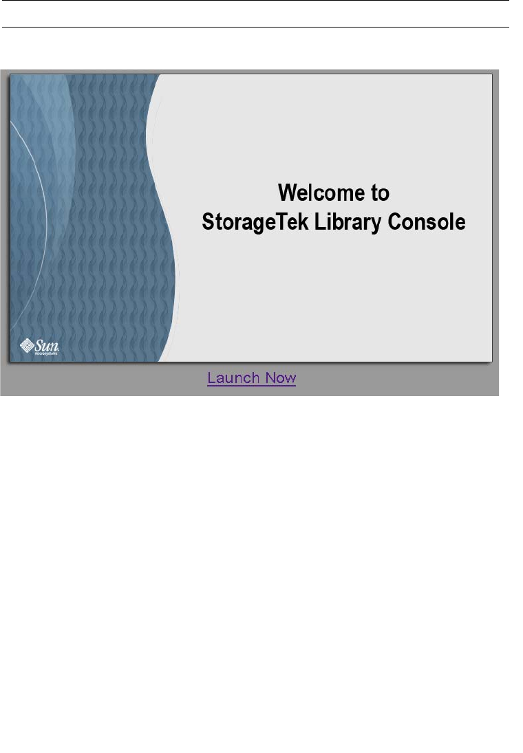
Web-launched SL Console
44 SL500 User’s Guide • July 2008 Revision: KA • 96116
3. Start a supported Web browser on your client PC or workstation (see “Client
Requirements” on page 42 for a list of supported browsers), and in the Location Bar
or Address field, enter the URL of the SL Console Web Start application:
http://server_ID/opel
where:
■server_ID is either of the following:
■IP address of the SL Console server (in nnn.nnn.nnn.nnn format)
■DNS alias of the SL Console server
■opel is the name (context root) of the Web-launched SL Console application on the
server.
Note – You can bookmark this URL for future logins.
4. The SL Console Launch screen appears. Click Launch Now.
The Web Start process retrieves the Web-launched SL Console application from the
server. Any updates are downloaded automatically.
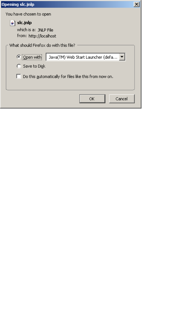
Web-launched SL Console
96116 • Revision: KA Chapter 2 StorageTek Library Console 45
5. The Opening slc.jnlp popup appears.
Complete the popup as follows:
a. Specify the action you want to take with the slc.jnlp file:
■Click the Open with Java(TM) Web Start Launcher radio button if you want to
start the SL Console directly.
■Click the Save to Disk radio button if you want to save the slc.jnlp file to your
client and log in to the SL Console later. See “Log in to the Web-launched
SL Console Using an Icon” on page 49 for login instructions.
b. Optionally click the “Do this automatically for files like this from now on”
checkbox. If you make this selection, this popup will not appear during future
logins.
c. Click OK.
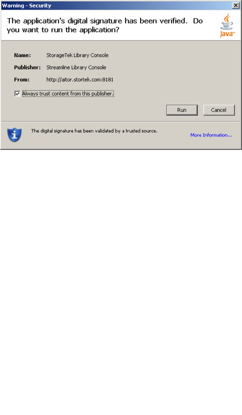
Web-launched SL Console
46 SL500 User’s Guide • July 2008 Revision: KA • 96116
6. If this is the first time you are running the Web-launched SL Console, a digital
signature warning popup appears.
Complete the popup as follows:
a. Verify the Publisher.
b. Optionally click the “Always trust content from the publisher” checkbox. If you
make this selection, this popup will not appear during future logins.
c. Click Run.

Web-launched SL Console
96116 • Revision: KA Chapter 2 StorageTek Library Console 47
7. If this is the first time you are running the Web-launched SL Console, the License
Agreement popup appears.
Scroll down to read the complete license agreement. Click, “I accept the terms of the
License Agreement”, and then click OK.
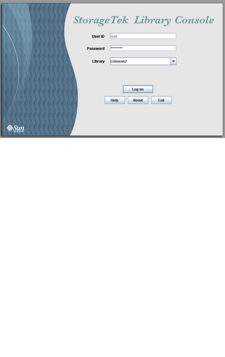
Web-launched SL Console
48 SL500 User’s Guide • July 2008 Revision: KA • 96116
8. The SL Console Login screen appears.
Enter your login information, and click Log on.
User ID: SLC_login
Password: password
Library: library_ID
where:
■SLC_login is the SL Console user ID.
■password is the password assigned to this user ID.
■library_ID is the library to which you want to connect, expressed in either of the
following ways:
■IP address of the library, in dotted decimal notation (nnn.nnn.nnn.nnn)
■DNS alias of the library
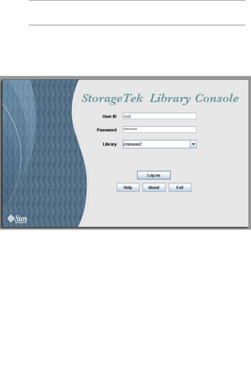
Web-launched SL Console
96116 • Revision: KA Chapter 2 StorageTek Library Console 49
▼ Log in to the Web-launched SL Console Using an
Icon
Note – In order to perform this activity, you must first save the Web-launched
SL Console slc.jnlp file to your client. See “Log in to the Web-launched SL Console
Using a Browser or Command Line” on page 43 for details.
1. Double-click the slc.jnlp desktop icon on your client.
The Web Start process retrieves the Web-launched SL Console application from the
server. Any updates are downloaded automatically.
■IP address of the library, in dotted decimal notation (nnn.nnn.nnn.nnn)
■DNS alias of the library
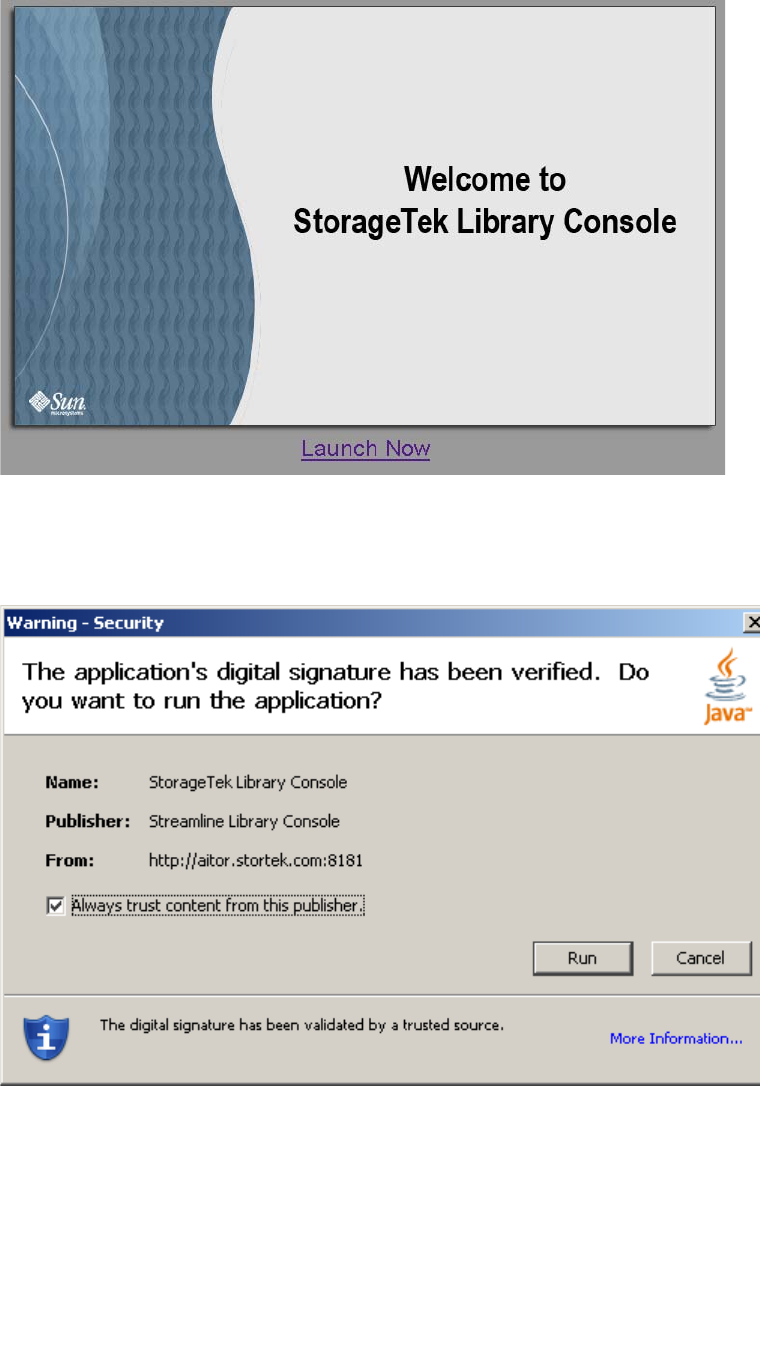
Web-launched SL Console
50 SL500 User’s Guide • July 2008 Revision: KA • 96116
2. The SL Console Launch screen appears. Click Launch Now.
The Web Start process retrieves the Web-launched SL Console application from the
server. Any updates are downloaded automatically.
3. If this is the first time you are running the Web-launched SL Console, a security
warning popup appears.
Complete the popup as follows:
a. Verify that the Publisher is Sun Microsystems, Inc.
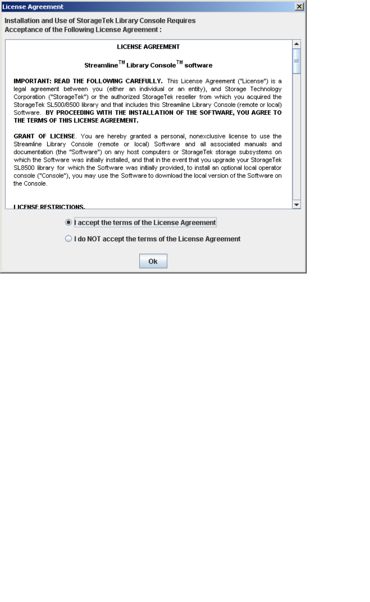
Web-launched SL Console
96116 • Revision: KA Chapter 2 StorageTek Library Console 51
b. Optionally click the “Always trust content from the publisher” checkbox. If you
make this selection, this popup will not appear during future logins.
c. Click Yes.
4. If this is the first time you are running the Web-launched SL Console, the License
Agreement popup appears.
Scroll down to read the complete license agreement. Click, “I accept the terms of the
License Agreement”, and then click OK.
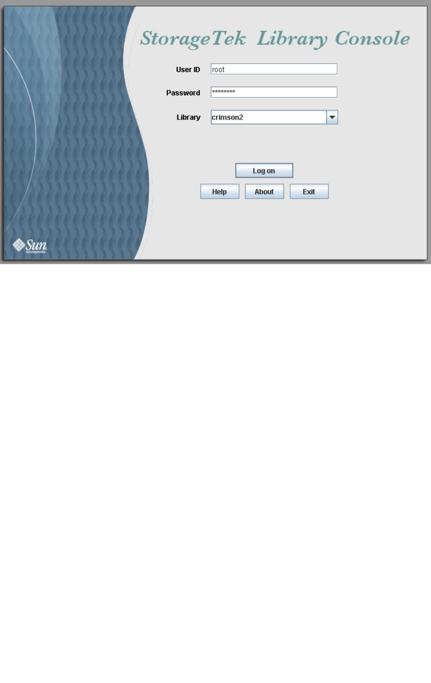
Web-launched SL Console
52 SL500 User’s Guide • July 2008 Revision: KA • 96116
5. The SL Console Login screen appears.
Enter your login information, and click Log on.
User ID: SLC_login
Password: password
Library: library_ID
where:
■SLC_login is the SL Console user ID.
■password is the password assigned to this user ID.
■library_ID is the library to which you want to connect, expressed in either of the
following ways:
■IP address of the library, in dotted decimal notation (nnn.nnn.nnn.nnn)
■DNS alias of the library

SL Console Reports
96116 • Revision: KA Chapter 2 StorageTek Library Console 53
SL Console Reports
The SL Console reports provide information on the library and its associated devices
(for example, drives, robots, and CAPs), events, and tape cartridges. You can use the
library reports to monitor library activity and identify potential problems. In addition
to displaying the reports on-screen, you can save the report data to a file, which you
can then print or include in e-mail.
All report output is a static display of information sent from the library controller at the
time the report is generated. The SL Console does not update the information
dynamically unless you explicitly select the Update button on the Options bar.
Note – Running multiple instances of the standalone SL Console or Web-launched
SL Console on the same PC or workstation can cause problems such as inconsistent
data on reports. It is recommended that only one user at a time produce SL Console
reports on a PC or workstation, unless all instances of the SL Console are the same
version.
Report Types
The SL Console provides the following types of reports:
■Log—detailed system event logs
■Statistics—statistical information on library operations
■Status Detail—details on the status of the library and associated devices, such as
CAPs, drives, and robots
■Status Summary—summary information on the status of the library and associated
devices
■Version—details about library hardware and software versions
▼ Generate a Report
1. Select Tools > Reports.
2. On the report tree, expand the folder containing the report you want to generate
(Log, Statistics, Status Detail, Status Summary, or Version).
3. Click the name of the report you want to generate.
4. The current report data is displayed.
SL Console Reports
54 SL500 User’s Guide • July 2008 Revision: KA • 96116
Report Options Bar
The Options bar on each report allows you to perform the following functions:
■Search the report for a specified text string
■Update the report with current data
■Save the data to a file
▼ Search the report for a specified text string
1. Click Search.
2. In the Search Text box, enter the text string you want to search for. The entry is case-
sensitive. Wildcards are not supported.
3. Click Search.
All occurrences of the string are highlighted.
▼ Update the report with current data
1. Click Update.
The screen display is refreshed with current data from the library controller.
▼ Save the data to a file
1. Click Save.
2. In the Save In pull-down menu, select a folder.
3. In the File Name box, enter the file name to which you want to save the data.
4. In the Files of Type pull-down menu, select the format in which you want to save the
data (HTML, Text, or XML).
5. Click Save.
Note – If the file exists already, the system prompts you to verify that you want to
replace it.
Once saved, you can print the file or include it in e-mail. This may be useful for
communicating about issues with your Sun service representative.
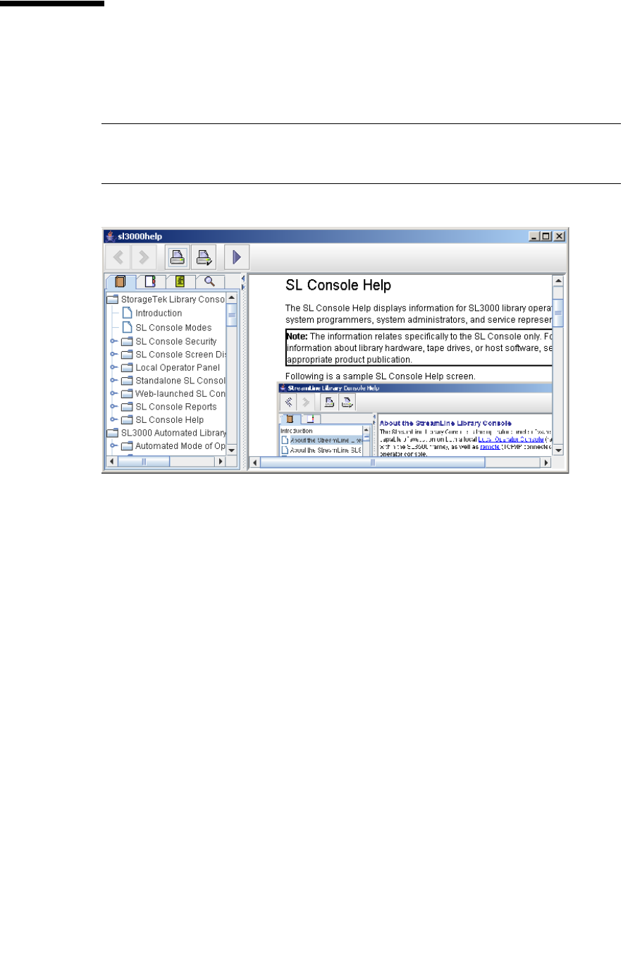
SL Console Help
96116 • Revision: KA Chapter 2 StorageTek Library Console 55
SL Console Help
The SL Console Help displays information for library operators, system programmers,
system administrators, and service representatives.
Note – The information relates specifically to the SL Console only. For information
about library hardware, tape drives, or host software, see the appropriate product
publication.
Following is a sample SL Console Help screen.
▼ Access the SL Console Help
You can display the SL Console Help from any SL Console screen. Use either of the
following methods:
■To display context-sensitive help for the current SL Console screen, click the ? button
in the Options bar.
■To display general help information, click Help > Contents in the Menu bar.
Help Navigation
The left panel of the SL Console Help screen displays either of the following:
■Table of contents (TOC)—An outline of topics and subtopics
■Index—A list of terms and topics, in alphabetical order
The right panel displays the Help topic itself.
SL Console Help
56 SL500 User’s Guide • July 2008 Revision: KA • 96116
The top of the SL Console Help screen includes the following navigation buttons.
Tips for Using the SL Console Help
■You can minimize, maximize, or resize the Help screen to accommodate your needs.
■You can resize the left and right panels of the Help screen by clicking the border
between them and dragging it left or right.
■Most topics include a Related Topics button at the bottom of the page. Click on this
button to display and navigate to help topics containing related information.
Button Action
Back Retraces your steps, going backward one topic at a time.
Forward Retraces your steps, going forward one topic at a time.
Print Displays the Print popup, which allows you to print one or
more topics:
■To print the current topic, click the Print button.
■To print a different topic, click the topic title in the
SL Console Help table of contents, and click the Print button.
■To print more than one topic, highlight the topics in the
SL Console Help table of contents by pressing Shift-Click or
Ctrl-Click, and then click the Print button.
Print Setup Displays the Page Setup popup, which allows you to modify
your print page layout.
TOC Displays the SL Console Help table of contents.
Index Displays the SL Console Help index.

96116 • Revision: KA 57
CHAPTER 3
SL500 Automated Library Operations
Automated Mode of Operation
When in automated mode of operation, the library automatically mounts and
dismounts cartridges without physical intervention by a person.
Automated operations include the following activities:
■Mounting and dismounting cartridges
■Entering and ejecting cartridges through the CAP
■Logging library events
■Drive cleaning
Cartridge Mount and Dismount Activities
The primary function of the library is the automated mounting and dismounting of
cartridges. Host mount and dismount commands are accepted by the library controller
and translated into robotic commands that are performed by the HandBot.
Mount Sequence
A simplified mount sequence involves the following steps:
1. A host requests that a specific volume serial number (VOLID) be mounted in a drive.
2. The library controller transmits to the host that the VOLID is located within the
library and a drive is available to satisfy the mount request.
3. The library assumes responsibility for the mount.
4. The host command is translated by the library controller into motion commands for
the HandBot.
5. The cartridge is taken from its storage cell and placed in the drive.
6. The library returns status to the host that the mount operation is completed.
7. The drive performs the read/write activity directed by the host.

Automated Mode of Operation
58 SL500 User’s Guide • July 2008 Revision: KA • 96116
Dismount Sequence
A simplified dismount sequence involves the following steps:
1. A host requests that a specific VOLID be dismounted from a drive.
2. The library controller transmits to the host that the VOLID is located in the drive and
the library is available to satisfy the dismount request.
3. The library assumes responsibility for the dismount.
4. The host command is translated by the library controller into mechanical commands
for the HandBot.
5. The cartridge is taken from the drive and placed into its home cell.
6. The library returns status to the host that the dismount operation is completed.
Determining When the Library is Not in Automated
Mode
The library is not in automated mode when it is not able to accept host requests. The
following conditions indicate that the library is not in automated mode:
■A library access door is open.
■The HandBot does not automatically mount and dismount cartridges.
■The device tree in the SL Console indicates that there is a problem with the library.
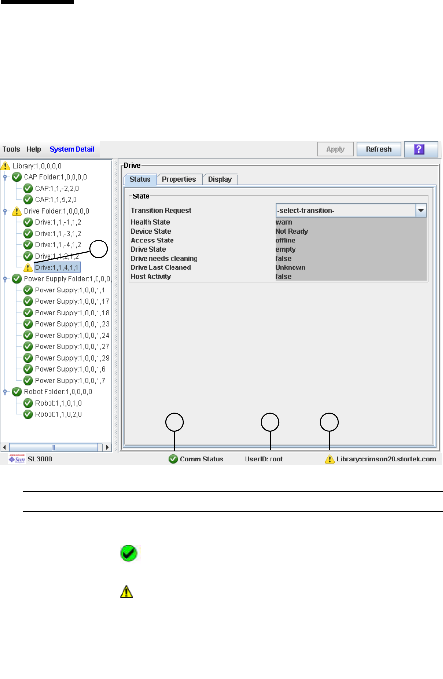
Library and Device Status
96116 • Revision: KA Chapter 3 SL500 Automated Library Operations 59
Library and Device Status
The SL Console screen displays health indicators for each of the following devices:
■Library
■Drives
■CAPs
■Power supplies
■Robots (HandBot)
The following table describes the health monitor indicators.
Indicator Description
1Comm
Status
Current status of the communication channel between the SL Console and
the library controller. Possible icons are:
Normal communications. The heartbeat monitor flashes
periodically when the SL Console is communicating normally
with the library controller.
A warning. This icon appears when the server response takes
longer than 10 seconds.
21 3
4
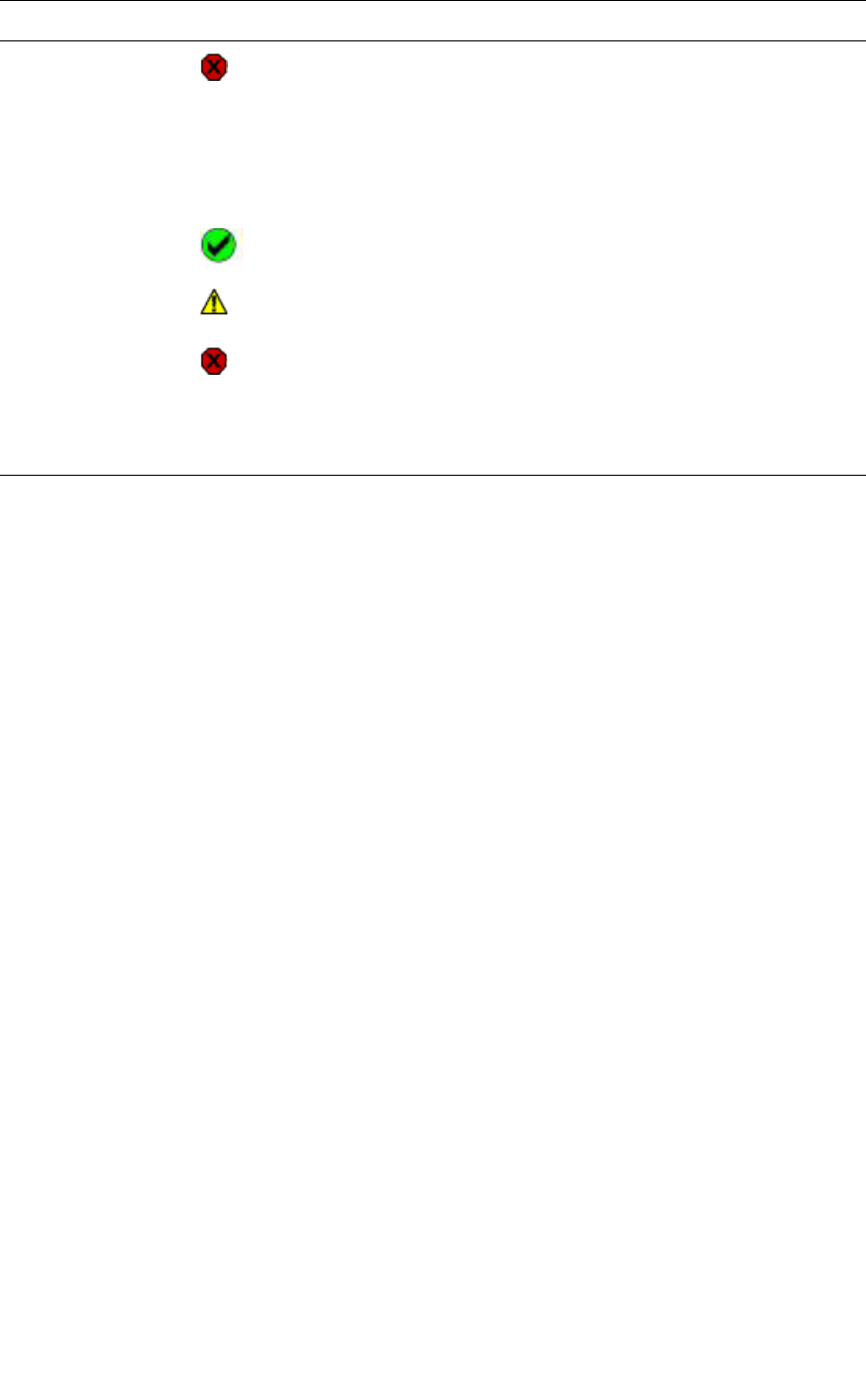
Library and Device Status
60 SL500 User’s Guide • July 2008 Revision: KA • 96116
Communications Failures
If the SL Console loses communication with the library controller, after about 30–60
seconds, the heartbeat monitor turns gray, then red, and the following error message
appears:
Heartbeat message not received from the library controller.
You must log off from the SL Console and then log on again to restore communication.
Viewing Library Information
The System Details > Library menu provides options for viewing and modifying
library information, such as library configuration and status and drive auto cleaning
configuration. For complete details, see the following topics:
■“Library Management Tasks” on page 66
■“Drive Cleaning Tasks” on page 105
An error. This icon appears when the server response takes
longer than 30 seconds.
2 Userid Userid currently logged in to the SL Console.
3 Library Library to which the SL Console is connected, and a graphical
representation of the current health of the library and its devices. Possible
icons are:
All library devices are functioning normally.
A warning. One or more devices in the library is offline or
operating in a degraded state.
An error. One or more devices in the library has experienced a
failure.
4Device
health
icon
Current status of the indicator device. When the library indicator shows a
warning or error, use this indicator to determine which devices are
experiencing abnormal conditions.
Indicator Description

CAP Operations
96116 • Revision: KA Chapter 3 SL500 Automated Library Operations 61
CAP Operations
Note – This section describes general CAP activities applying to all libraries. For
specific information on CAP activities in partitioned libraries, see “Partitions and
CAPs” on page 151.
CAPs (cartridge access ports) allow a library operator to enter or eject cartridges to or
from the library. You can use the CAPs only when the library is in automated mode.
The CAP in the Base Module has one five-cell magazine; the CAP in the Drive
Expansion Module has two five-cell magazines. Optionally, the CAP can be configured
for five (in Base Module) or ten (in expansion module) additional storage cells instead
of enter and eject operations.

Cartridge Management
62 SL500 User’s Guide • July 2008 Revision: KA • 96116
Cartridge Management
Recovery Moves
Note – This feature is available starting with SL500 firmware version 1026 and
SL Console version 2.40.
Using the recovery move diagnostic function, you can move a cartridge from one
location to another. For example:
■You can return a cartridge to its original location from a CAP cell, drive, or another
storage cell location.
■You might decide to group cartridges by data type or to move them closer to their
assigned drives.
■You can eject a cleaning or diagnostic cartridge that has expired.
■You can enter a new cleaning or diagnostic cartridge and move it to a reserved
storage cell.
A cartridge currently in a storage cell can be moved only to a CAP, a reserved cell, or
another storage cell, not to a drive. A cartridge currently in a drive, CAP, or reserved
cell can be moved to any other unoccupied location in the library. See the following
procedures for complete details:
■“Move a Specified Cartridge by VOLID” on page 89
■“Move a Cartridge From a Specified Location” on page 93
Before moving any cartridge, it is helpful to generate a Cartridge Summary Report,
which lists the contents of library storage cells. See “List Library Cartridges” on page 88
for details. This report helps you determine where cartridges are currently located and
which storage cells are unoccupied.

Drive Cleaning
96116 • Revision: KA Chapter 3 SL500 Automated Library Operations 63
Drive Cleaning
The library tape drives require periodic cleaning to prevent read and write errors. The
library supports two methods of drive cleaning:
■Automatic Cleaning
■Manual Cleaning
Cleaning Cartridges
Note – You must use cleaning cartridges whose media types are compatible with the
drive types in the library.
Cleaning cartridges have a limited life span. Refer to your tape drive publications to
determine the maximum usage count, or threshold, for each type of cleaning cartridge.
When you enter a cleaning cartridge into the library, the library controller considers the
cartridge to be new and sets the usage count to zero. It is therefore important to enter
only new cleaning cartridges into the library.
Whenever a cleaning cartridge is used to clean a drive, its usage count is incremented.
When a cleaning cartridge’s usage count exceeds its threshold, the cartridge must be
replaced.
You can use the SL Console to display the status of a cleaning cartridge at any time.
The following statuses are possible:
■OK—The cartridge is still within the threshold.
■Warning—The cartridge has reached the threshold.
■Expired—The cartridge has exceeded the threshold.
Ejecting Expired Cleaning Cartridges
You must use care when ejecting expired cleaning cartridges from the library. If you
move an expired cleaning cartridge to a CAP and open the CAP, you must remove the
cartridge. If you close the CAP without removing the cleaning cartridge first, the
HandBot will re-enter the expired cartridge into the library, and the library controller
will reset the usage count to zero.
Automatic Cleaning
When auto clean is enabled, the library controller automatically initiates a cleaning
operation whenever a drive requires cleaning. The HandBot retrieves an appropriate
cleaning cartridge (based on drive type) from the reserved cells, mounts the cartridge
onto the drive, and returns the cartridge to its assigned storage cell after cleaning is
complete.

Drive Cleaning
64 SL500 User’s Guide • July 2008 Revision: KA • 96116
Manual Cleaning
If auto clean is disabled, you must initiate drive clean operations manually. To verify
whether a drive needs cleaning, you can use the SL Console to display a drive’s
cleaning status and the date when it was last cleaned.
Even if auto clean is enabled, you may want to clean a drive before it is due. Therefore,
you can initiate a manual clean at any time.
To locate the correct type of cleaning cartridge for a particular drive, you can use the
SL Console to generate a cartridge summary and drive details report.

Automated Operation Tasks
96116 • Revision: KA Chapter 3 SL500 Automated Library Operations 65
Automated Operation Tasks
Library automated operation tasks are divided into the following categories:
■“Library Management Tasks” on page 66
■“CAP Management Tasks” on page 80
■“Cartridge Management Tasks” on page 84
■“Drive Management Tasks” on page 98
■“Drive Cleaning Tasks” on page 105
■“Robot Monitoring Tasks” on page 115

Library Management Tasks
66 SL500 User’s Guide • July 2008 Revision: KA • 96116
Library Management Tasks
Task Page
Display Library Status 67
Display Library Configuration Information 68
Set the Library Fibre Channel Port Address 69
Display Library Controller Properties 71
Display Library Physical Configuration 72
Display Library Statistics 73
Display a Library Report 74
Search a Library Report 76
Save Library Report Data to a File 78
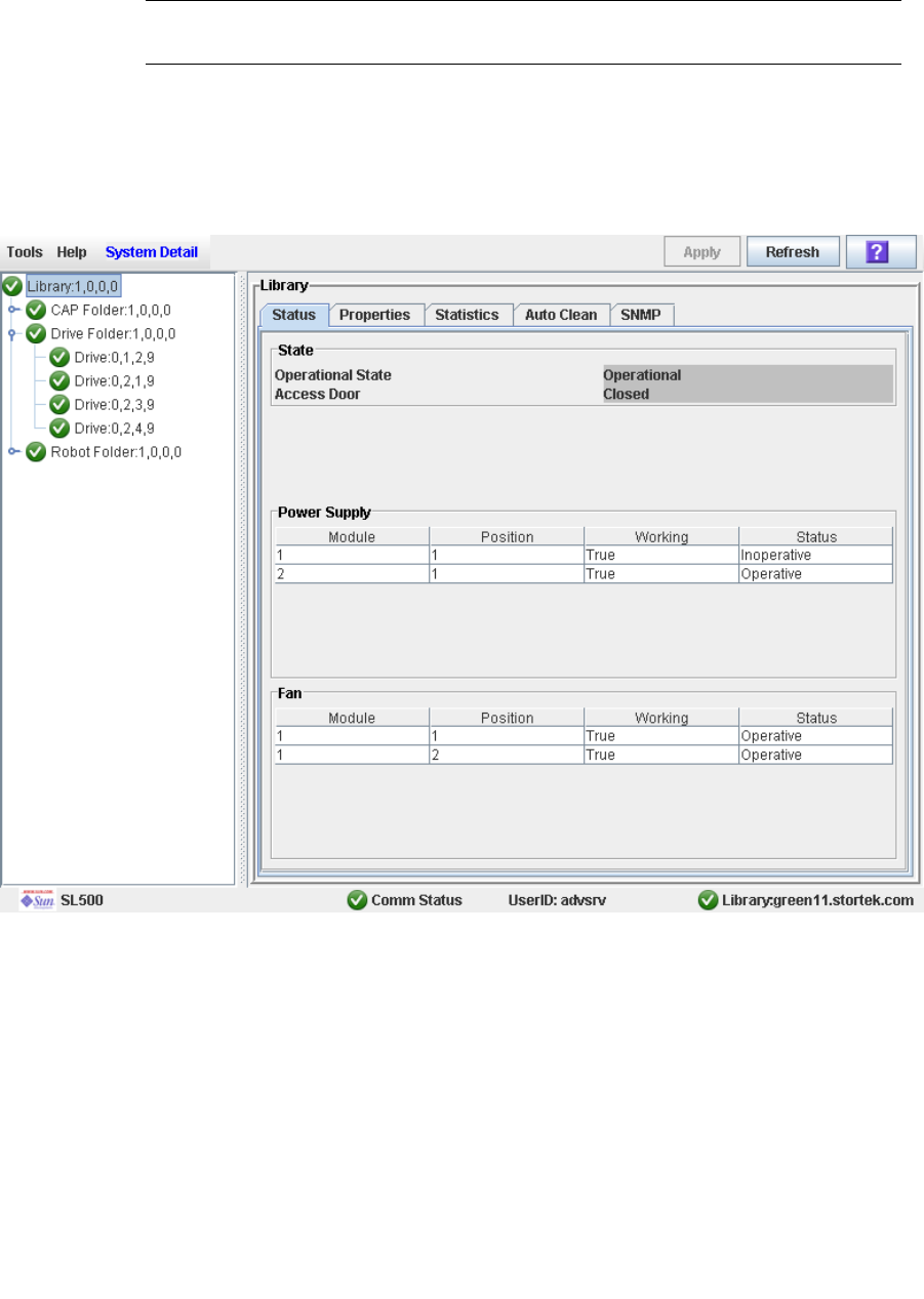
Library Management Tasks
96116 • Revision: KA Chapter 3 SL500 Automated Library Operations 67
▼ Display Library Status
View the current operational state of the library. These values are updated whenever
there is host activity, background operations, or operator activity.
Note – This information is also available through Reports > Library Details. See
“Display a Library Report” on page 74 for detailed instructions.
1. Select Tools > System Detail.
2. Click the Library folder on the device tree.
3. Click the Status tab.
The screen displays the current status of the library.
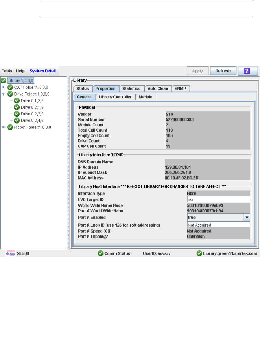
Library Management Tasks
68 SL500 User’s Guide • July 2008 Revision: KA • 96116
▼ Display Library Configuration Information
Use this procedure to display the physical, mechanical, and logical configuration of the
library. Some of the information can is set up automatically during library initialization,
while other information can be defined by the user.
Note – This information is also available through Reports > Library Information. See
“Display a Library Report” on page 74 for detailed instructions.
1. Select Tools > System Detail.
2. Click the Library folder on the device tree.
3. Click the Properties tab, and then the General tab.
The screen displays detailed information about the library.
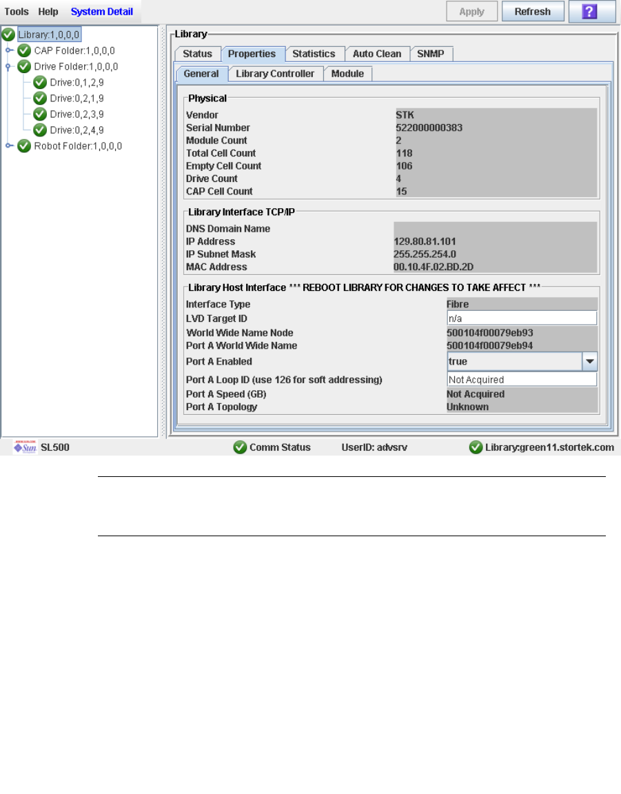
Library Management Tasks
96116 • Revision: KA Chapter 3 SL500 Automated Library Operations 69
▼ Set the Library Fibre Channel Port Address
If the control path for the library is Fibre Channel, you must enable the Library’s Fibre
Channel Port (port A). The Fibre Channel Port A address locates the library’s Port A on
the Fibre Channel loop.
1. Select Tools > System Detail, and select the Library folder from the device tree.
2. Select Properties > General.
The screen displays detailed information about the library.
Note – The screen includes the library’s world wide ID (the node ID) and the Port A
world wide name ID (the port ID). These two IDs are set at the factory and cannot be
changed. Each ID is 64 bits and uses the IEEE registered format.
■To enable soft addressing:
a. Select True from the Port A Enabled drop-down list to enable Port A.
b. Set the Port A Loop Id to 126.
■To enable hard addressing:
a. Select False from the Port A Enabled drop-down list to disable Port A.
b. Set the Port A Loop ID to value between 1-125.

Library Management Tasks
70 SL500 User’s Guide • July 2008 Revision: KA • 96116
c. Select Apply to save the changes.
3. Reboot the library for the changes to take effect.
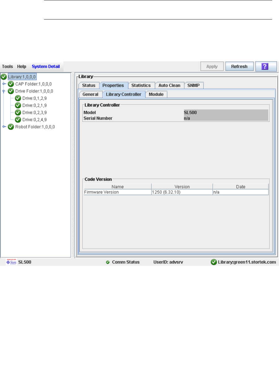
Library Management Tasks
96116 • Revision: KA Chapter 3 SL500 Automated Library Operations 71
▼ Display Library Controller Properties
View details of the library controller, including the serial number and firmware
versions.
Note – This information is also available through Reports > Library Information. See
“Display a Library Report” on page 74 for detailed instructions.
1. Select Tools > System Detail.
2. Click the Library folder on the device tree.
3. Click the Properties tab, and then the Library Controller tab.
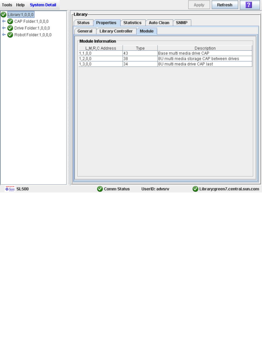
Library Management Tasks
72 SL500 User’s Guide • July 2008 Revision: KA • 96116
▼ Display Library Physical Configuration
View the current physical configuration of the library.
1. Select Tools > System Detail.
2. Click the Library folder on the device tree.
3. Click the Properties tab, and then the Module tab.
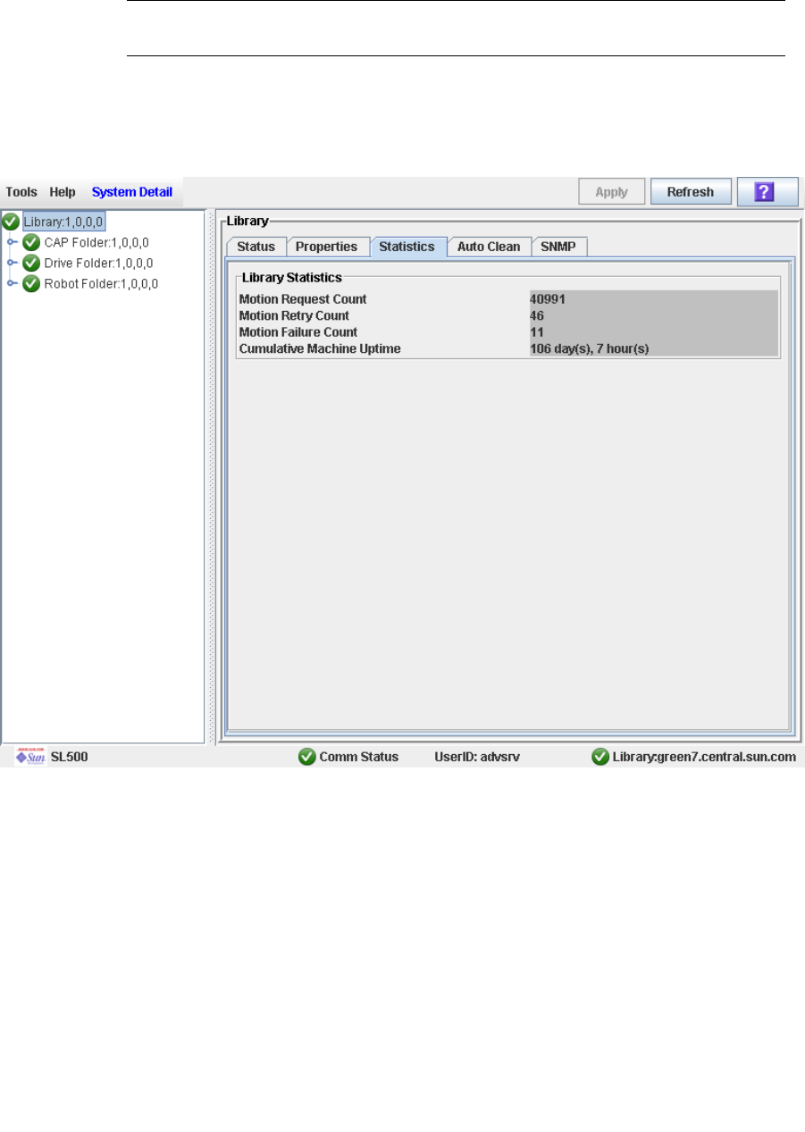
Library Management Tasks
96116 • Revision: KA Chapter 3 SL500 Automated Library Operations 73
▼ Display Library Statistics
Use this procedure to view library statistics, such as the request, retry, and failure count
of the robot and the library uptime.
Note – This information is also available through Reports > Statistics. See “Display a
Library Report” on page 74 for detailed instructions.
1. Select Tools > System Detail.
2. Click the Library folder on the device tree.
3. Click the Statistics tab.
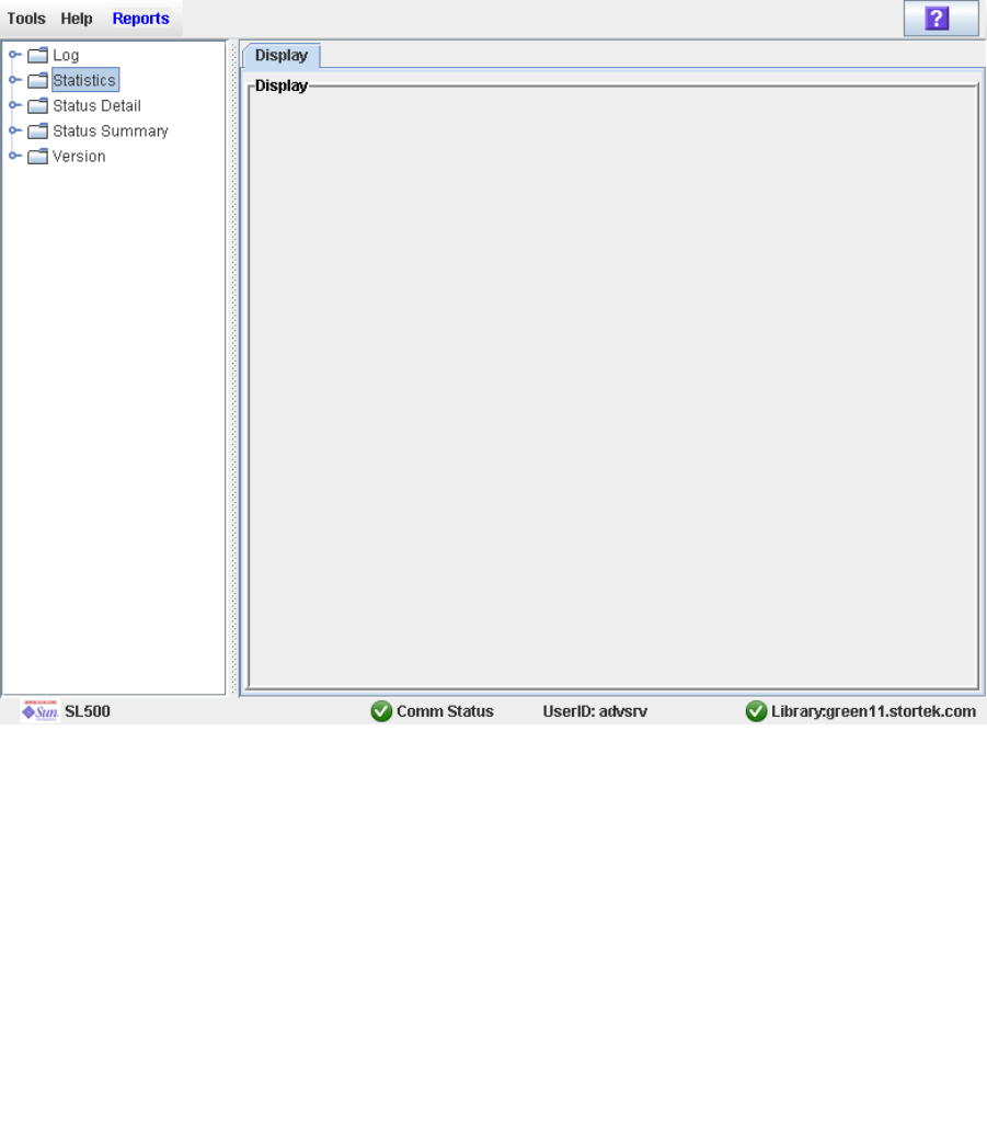
Library Management Tasks
74 SL500 User’s Guide • July 2008 Revision: KA • 96116
▼ Display a Library Report
Use this procedure to display library reports available from the Tools > Reports menu.
Additionally, if you want to search the report data or save it to a file, see the following
procedures:
■“Search a Library Report” on page 76
■“Save Library Report Data to a File” on page 78
Additional reports are available from the following menus:
■Tools > Partitions
1. Select Tools > Reports.
The reports Display screen appears. All library report options are listed in the
navigation bar.
2. In the navigation bar, expand a report category to see the report options.
3. Click the report you want to display.
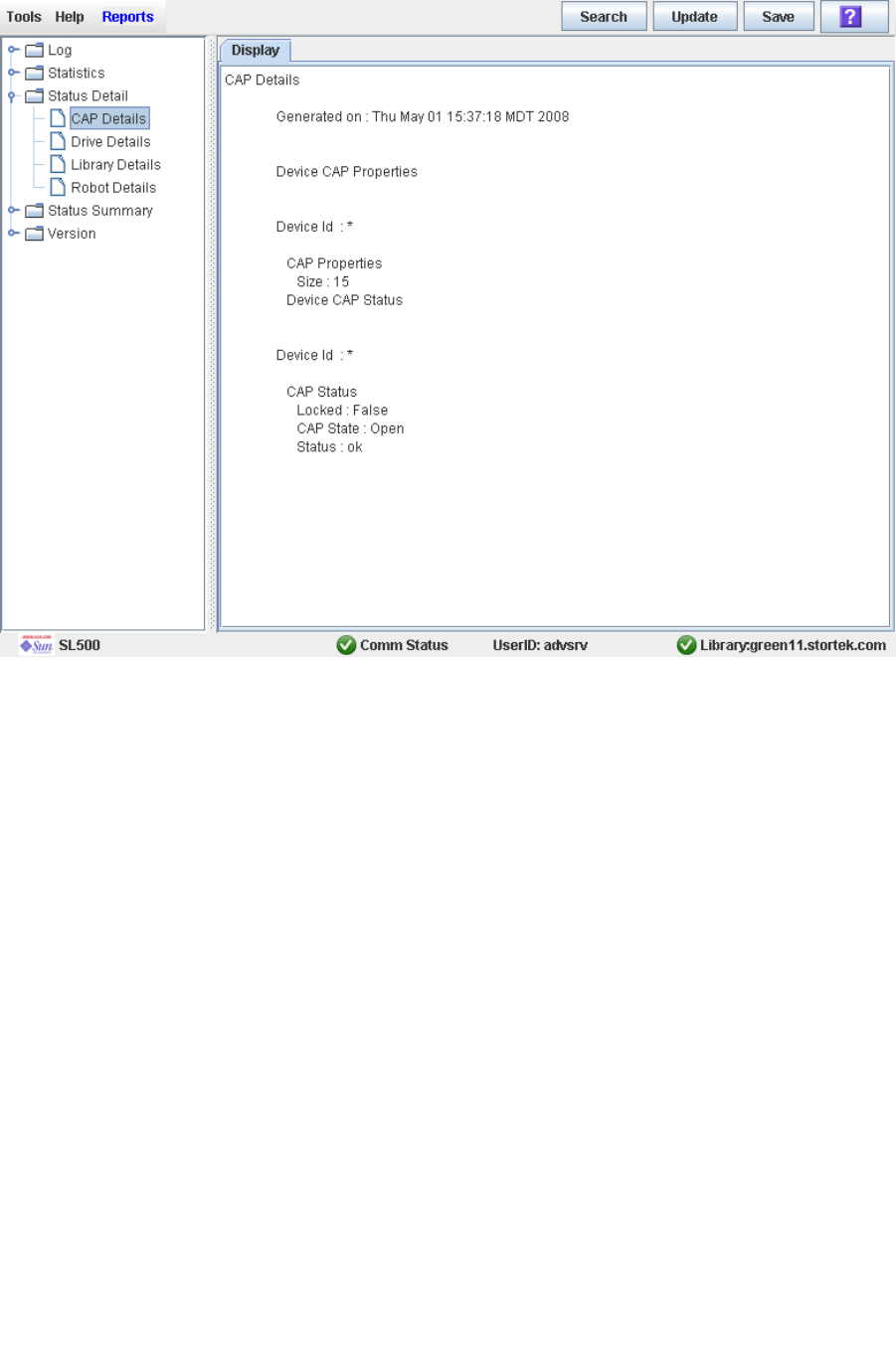
Library Management Tasks
96116 • Revision: KA Chapter 3 SL500 Automated Library Operations 75
The specified report is displayed.
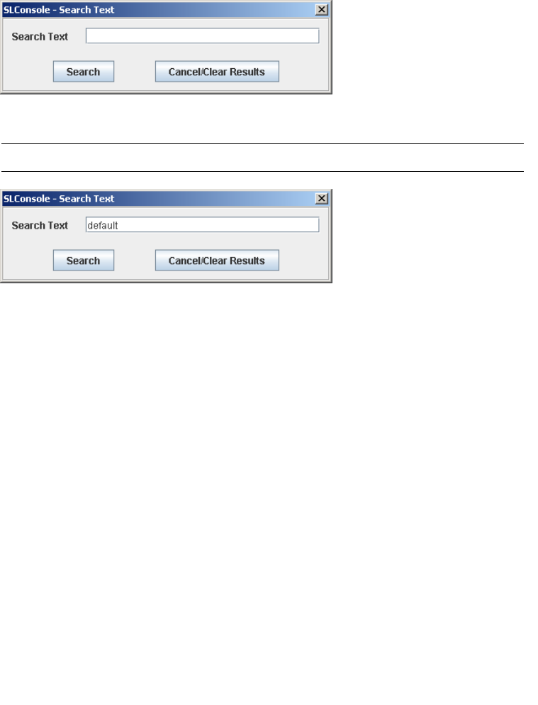
Library Management Tasks
76 SL500 User’s Guide • July 2008 Revision: KA • 96116
▼ Search a Library Report
Use this procedure to search a library report for a specified text string. This procedure
can be performed on any of the library report screens.
1. Select Tools > Reports.
The reports Display screen appears. All library report options are listed in the
navigation bar.
2. In the navigation bar, expand a report category to see the report options.
3. Click the report you want to display.
The specified report is displayed. All report screens include the Search button on the
Options Bar.
4. Click Search.
The Search Text popup appears.
5. Enter the text string you want to search for, and click Search.
Note – The search is case-sensitive, and wildcards are not supported.
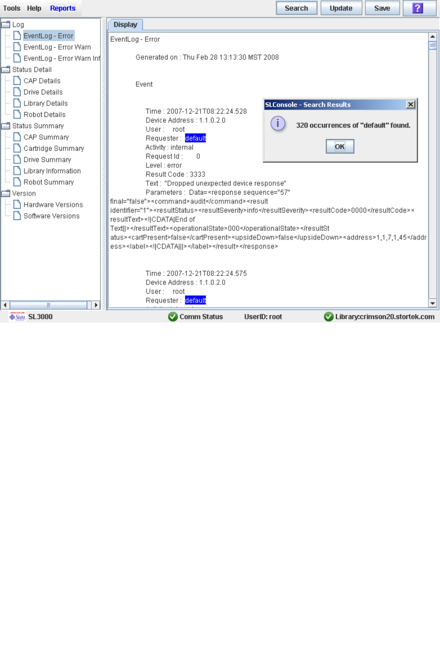
Library Management Tasks
96116 • Revision: KA Chapter 3 SL500 Automated Library Operations 77
6. The Search Results popup appears, displaying the number of occurrences of the text
string. All instances of the text string in the report are highlighted.
7. Click OK to dismiss the popup.
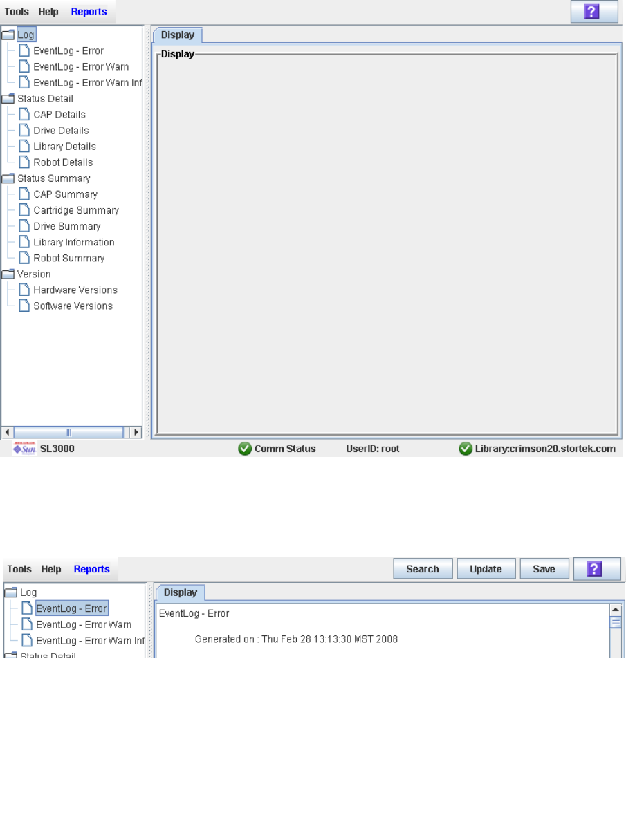
Library Management Tasks
78 SL500 User’s Guide • July 2008 Revision: KA • 96116
▼ Save Library Report Data to a File
Use this procedure to display a library report and save the data to a text (.txt) file.
This procedure can be performed from any of the library report screens.
1. Select Tools > Reports.
The reports Display screen appears. All library report options are listed in the
navigation bar.
2. In the navigation bar, expand a report category to see the report options.
3. Click the report you want to display.
The specified report is displayed. All report screens include the Save button on the
Options Bar.
4. Click Save.
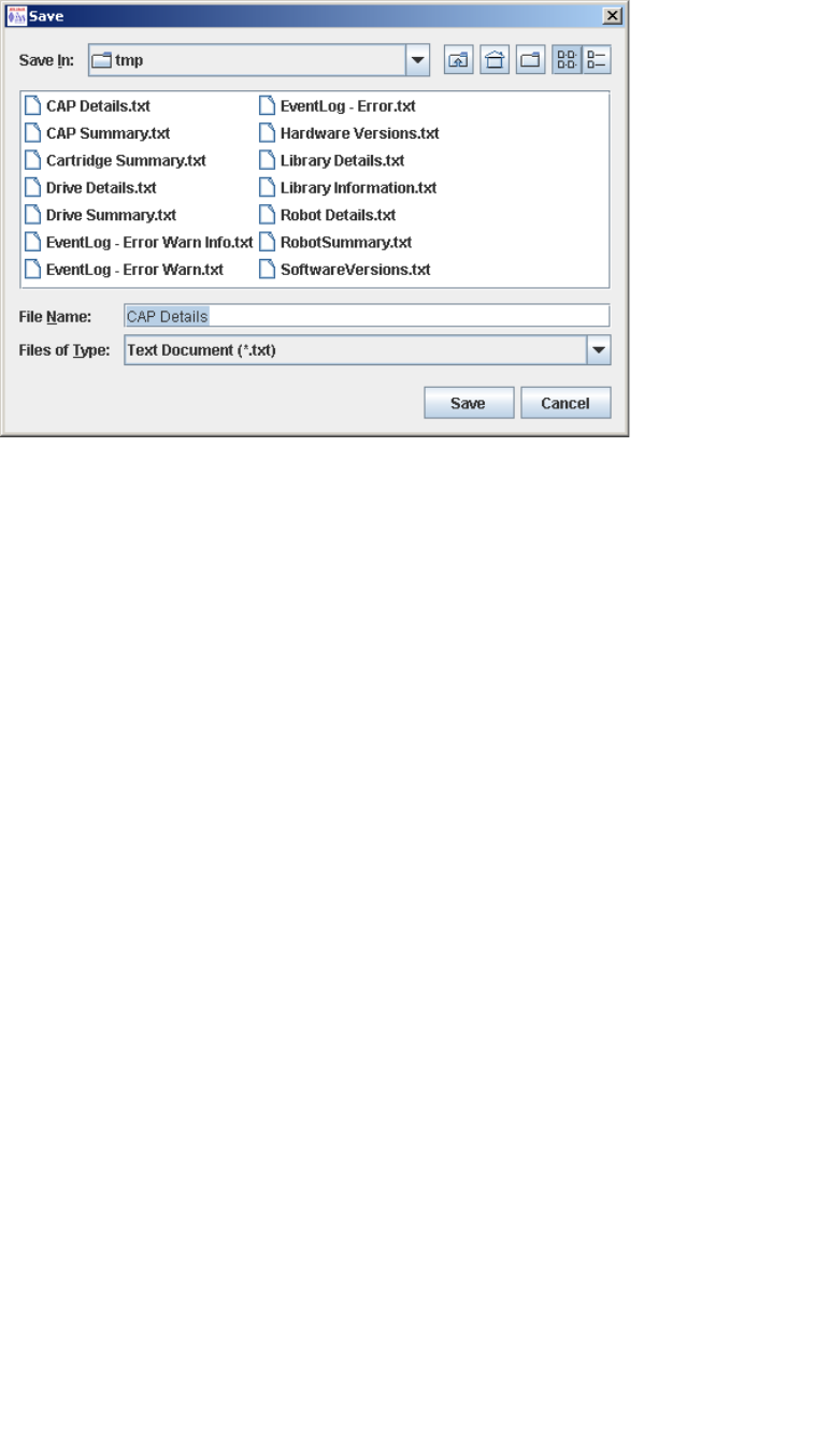
Library Management Tasks
96116 • Revision: KA Chapter 3 SL500 Automated Library Operations 79
The Save popup appears.
5. Browse to the directory where you want to save the file. In the File Name field, you
can accept the default entry or enter a different file name.
6. Click Save.
The data is saved to the specified file.

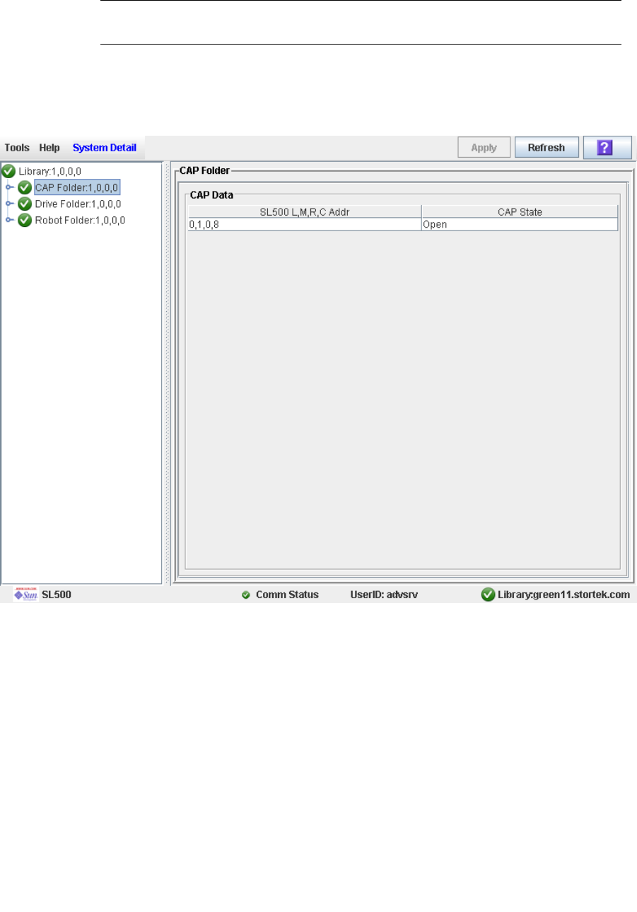
CAP Management Tasks
96116 • Revision: KA Chapter 3 SL500 Automated Library Operations 81
▼ Display CAP Summary Information
Use this procedure to display summary information for all CAPs in the library.
Note – This information is also available through Reports > CAP Summary. See
“Display a Library Report” on page 74 for detailed instructions.
1. Select Tools > System Detail. S
2. Click the CAP folder on the device tree.
The screen lists the library CAPs and their locations.
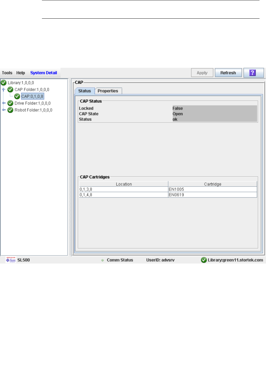
CAP Management Tasks
82 SL500 User’s Guide • July 2008 Revision: KA • 96116
▼ Display Current CAP Status
Use this procedure to display the current operational state of a CAP.
Note – This information is also available through Reports > CAP Details. See “Display
a Library Report” on page 74 for detailed instructions.
1. Select Tools > System Detail.
2. Expand the CAP Folder, and click the CAP you want to display.
3. Click Status.
The screen displays the current status of the selected CAP.
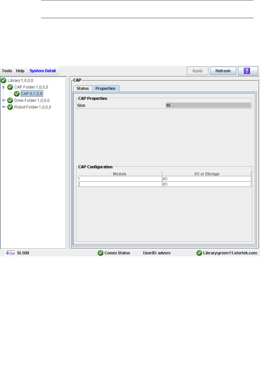
CAP Management Tasks
96116 • Revision: KA Chapter 3 SL500 Automated Library Operations 83
▼ Display CAP Properties
Use this procedure to display static CAP information, including the serial number and
number of cells.
Note – This information is also available through Reports > CAP Details. See “Display
a Library Report” on page 74 for detailed instructions.
1. Select Tools > System Detail.
2. Expand the CAP Folder, and click the CAP you want to display.
3. Click Properties.
The CAP Properties screen appears.

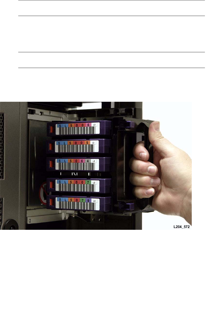
Cartridge Management Tasks
96116 • Revision: KA Chapter 3 SL500 Automated Library Operations 85
▼ Enter Cartridges Through the CAP
The Base Module CAP contains a standard four- or five-cell magazine. See FIGURE 3-1.
The expansion module CAP has two magazines.
Use this procedure to enter a cartridge into the library through a CAP.
Note – Before using this procedure, verify that the library CAP Prevent/Allow state is
set to Allow. See your SCSI reference manual for syntax.
1. Press the CAP Open button on the keypad.
The robot opens the CAP door and the CAP Open LED is turned on.
2. Grip the handle of the magazine and slide it out of the CAP and onto the door.
Note – Do not remove the magazine from the door. Leaving the magazine on the door
rails will allow the magazine to slide easier into the CAP.
3. Place the cartridge into one of the magazine cells, making sure that the VOLID label
is visible and the hub of the cartridge is down.
4. Grip the handle and slide the magazine back into the CAP.
5. Close the CAP door making sure that the door is securely latched.
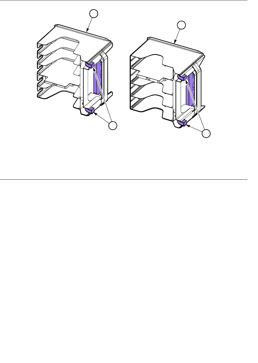
Cartridge Management Tasks
86 SL500 User’s Guide • July 2008 Revision: KA • 96116
6. Refer to your tape management software manual for syntax on how to move the
cartridges from the CAP to the storage cells.
FIGURE 3-1 Base Module Magazine Comparison
1. Five-cell LTO magazine
2. Four-cell mixed-media magazine
3. Cartridge release buttons
L204
_
557
1
2
3
3

Cartridge Management Tasks
96116 • Revision: KA Chapter 3 SL500 Automated Library Operations 87
▼ Eject Cartridges Through the CAP
Use this procedure to eject a cartridge from the library through a CAP.
1. Type the eject command at the host console. Refer to your tape management software
publication for the command syntax.
The robot places cartridges into the CAP cells until all the specified cartridges are in the
CAP.
2. Press the CAP Open button on the keypad.
3. The CAP is opened, and the CAP Open LED turns on.
4. Remove the ejected cartridges using either of the following methods:
■Leave the magazine in the CAP and remove the cartridges from it directly.
■Remove the magazine from the CAP and press the red cartridge release buttons to
remove the cartridges from the magazine.
5. If you removed the magazine from the CAP, place the magazine onto the door rails
and slide it back inside the CAP.
6. Close the CAP doors.
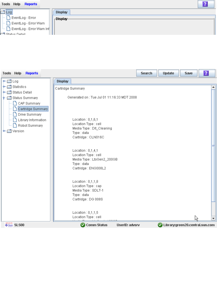
Cartridge Management Tasks
88 SL500 User’s Guide • July 2008 Revision: KA • 96116
▼ List Library Cartridges
Use this procedure to display information about all library cartridges, including their
VOLIDs, locations, and media types.
1. Select Tools > Reports.
All library report options are listed in the navigation bar.
2. Expand the Status Summary folder.
All Status Summary reports are listed.
3. Click Cartridge Summary.
The Cartridge Summary Report is displayed.
4. If you want to search the report data or save it to a file, see the following procedures:
■“Search a Library Report” on page 76
■“Save Library Report Data to a File” on page 78
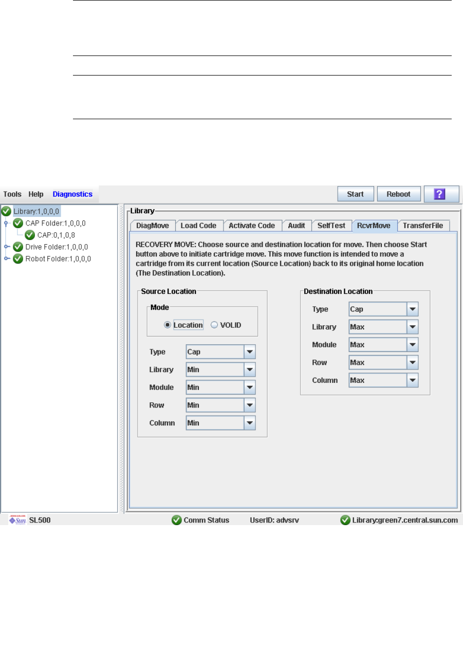
Cartridge Management Tasks
96116 • Revision: KA Chapter 3 SL500 Automated Library Operations 89
▼ Move a Specified Cartridge by VOLID
Use this procedure to move a cartridge with a specified VOLID to a specified location
within the library.
Note – This procedure updates the cartridge’s location in the library controller
database, but not in the host database. Therefore after performing this procedure, you
must perform an audit from the host software to update the host database. Failure to
do so will cause future mount requests from the host software to fail.
Caution – Use caution when performing this procedure in partitioned libraries. You
could inadvertently move a cartridge from one partition to another, allowing the new
partition to overwrite data on the cartridge.
1. Select Tools > Diagnostics, and click the Library folder.
2. Click the RcvrMove tab.
The Recovery Move screen appears.
3. In the Source Location Mode field, click VOLID.
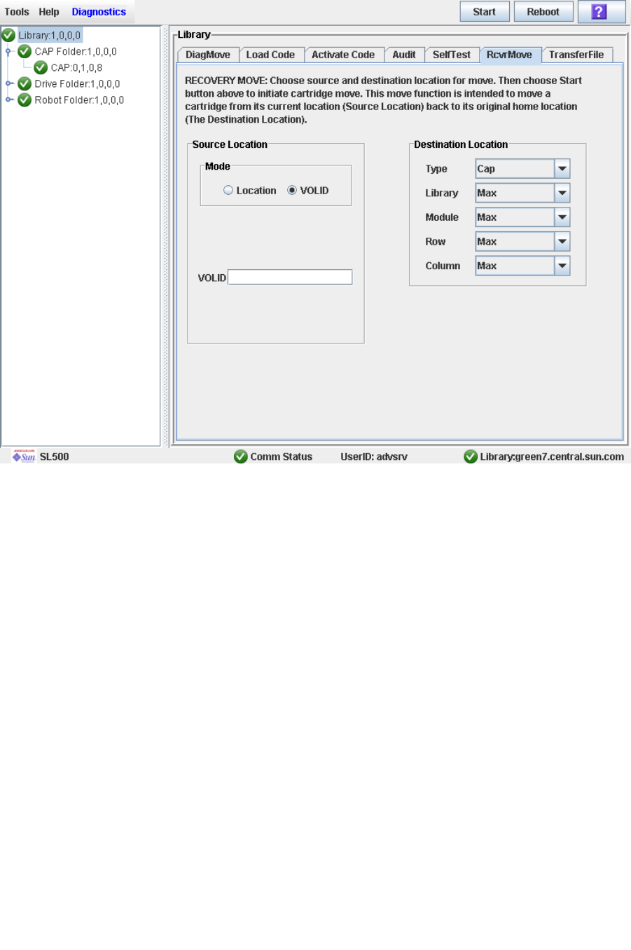
Cartridge Management Tasks
90 SL500 User’s Guide • July 2008 Revision: KA • 96116
The screen is updated with the appropriate Source Location fields.
4. In the VOLID field, specify the VOLID of the cartridge you want to move.
5. In the Destination Location Type pull-down menu, select the type of location where
you want to move the cartridge to. Options are:
■CAP
■Storage Slots
■Drive
■Reserved Slots
The following restrictions apply:
■The destination can be a drive only if the source is a CAP or reserved slot.
■For you to move a a cartridge to a drive, the cartridge media type must be
compatible with the drive type.
■You cannot move a cartridge to a location that is already occupied.
■Although not strictly enforced, it is recommended that only diagnostic or cleaning
cartridges be moved to reserved slots.
6. In the Destination Location table, specify the library internal address of the
destination location by making the appropriate selections in the following pull-
down menus:
■Library
■Module
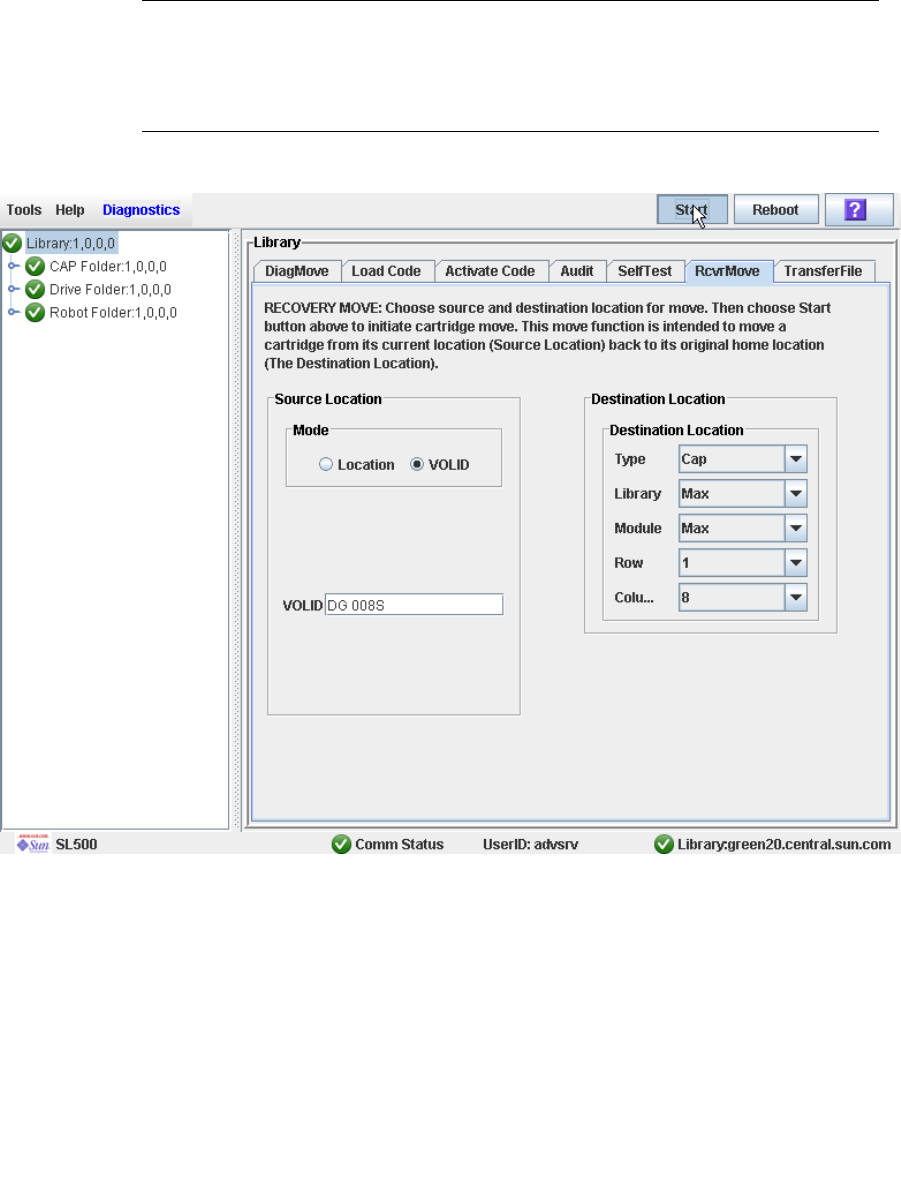
Cartridge Management Tasks
96116 • Revision: KA Chapter 3 SL500 Automated Library Operations 91
■Row
■Column
The following special selections are available on the pull-down menus:
■Min—First element of that location type—library, module, row, or column— in the
library
■Max—Last element of that location type—library, module, row, or column— in the
library
Caution – If the library is partitioned, make sure to keep the cartridge in the same
partition it is currently allocated to. Moving a cartridge to a cell allocated to a different
partition could result in a host treating the cartridge as scratch and overwriting the
data. Moving the cartridge to an unallocated cell will result in the cartridge being
inaccessible to all hosts.
7. Click the Start button in the Options Bar.
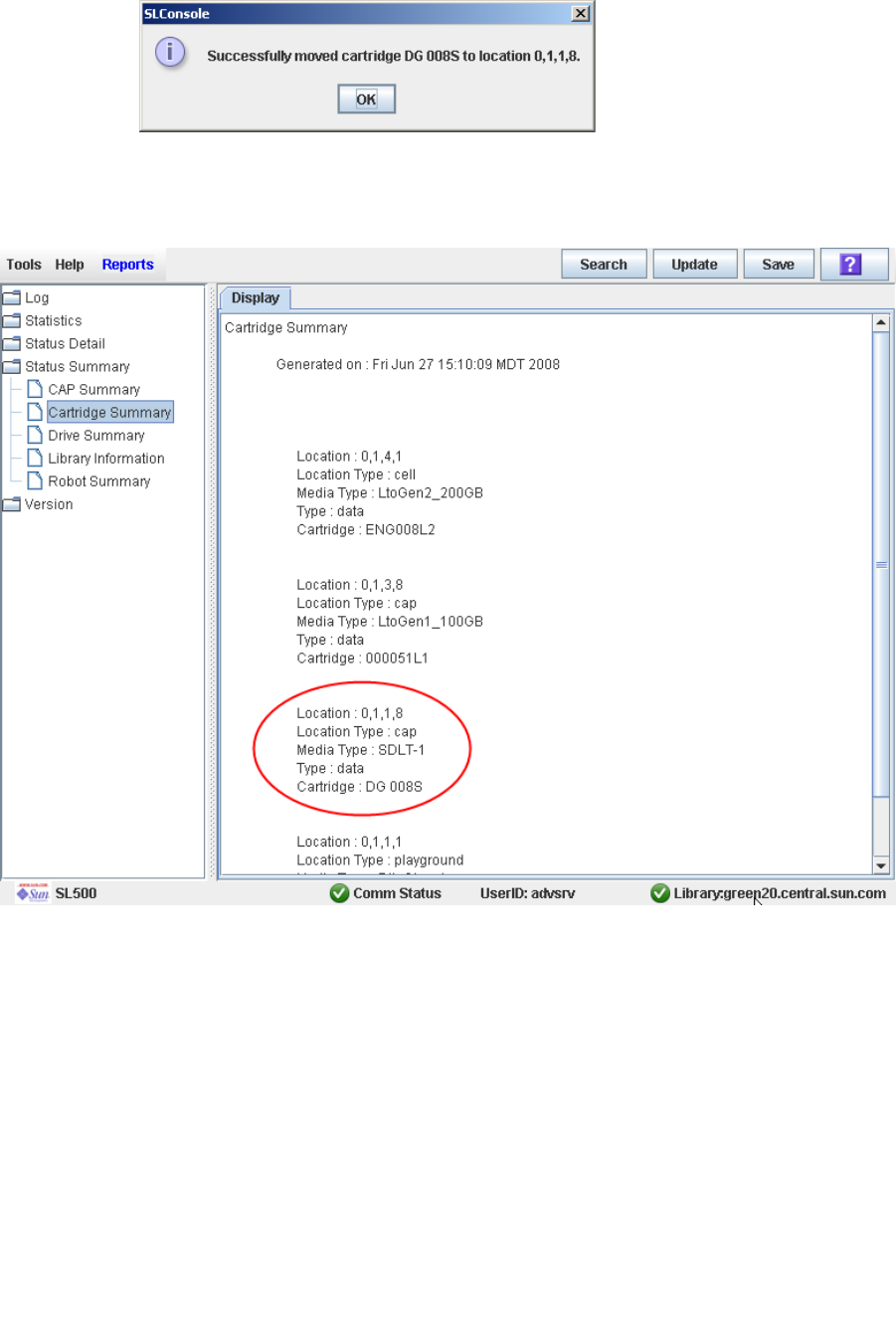
Cartridge Management Tasks
92 SL500 User’s Guide • July 2008 Revision: KA • 96116
The robot moves the cartridge. A success message popup appears when the operation
is complete.
8. Click OK.
9. To verify the new location, you can display a Cartridge Summary Report. See “List
Library Cartridges” on page 88 for details. For example:
10.To update the new cartridge location in the host database, initiate a library audit
from the host software. See the appropriate tape management software
documentation for the procedures and commands.
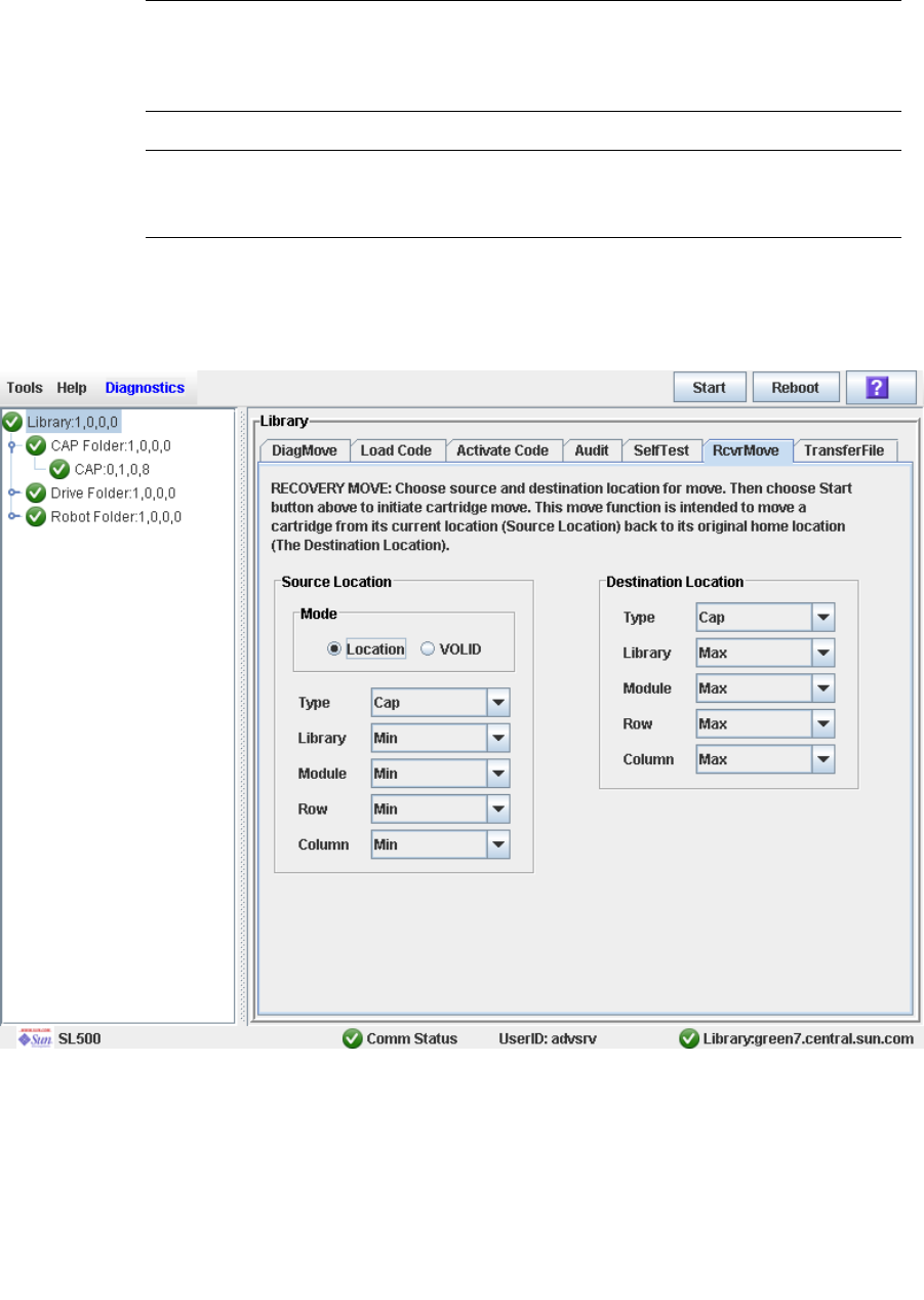
Cartridge Management Tasks
96116 • Revision: KA Chapter 3 SL500 Automated Library Operations 93
▼ Move a Cartridge From a Specified Location
Use this procedure to move a cartridge from one specified location to another within
the library.
Note – This procedure updates the cartridge’s location in the library controller
database, but not in the host database. Therefore after performing this procedure, you
must perform an audit from the host software to update the host database. Failure to
do so will cause future mount requests from the host software to fail.
Caution – Use caution when performing this procedure in partitioned libraries. You
could inadvertently move a cartridge from one partition to another, allowing the new
partition to overwrite data on the cartridge.
1. Select Tools > Diagnostics, and click the Library folder.
2. Click the RcvrMove tab.
The Recovery Move screen appears.
3. In the Source Location Mode field, click Location.
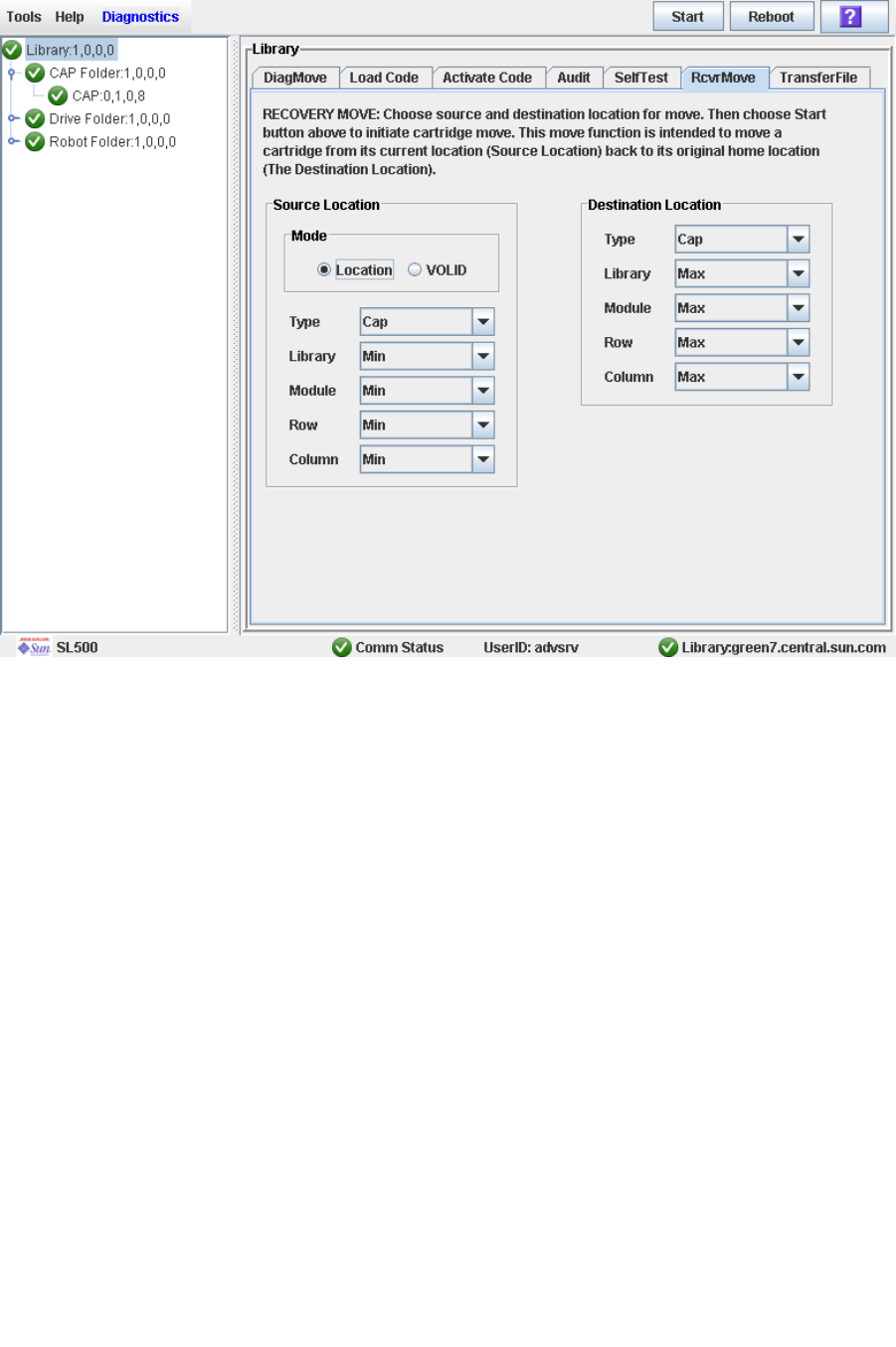
Cartridge Management Tasks
94 SL500 User’s Guide • July 2008 Revision: KA • 96116
The screen is updated with the appropriate Source Location fields.
4. In the Source Location Type pull-down menu, select the cartridge’s current location
type. Options are:
■CAP
■Slot
■Drive
■Reserved Slots
5. In the Source Location table, specify the library internal address of the source
location by making the appropriate selections in the following pull-down menus:
■Library
■Module
■Row
■Column
The following special selections are available on the pull-down menus:
■Min—First element (library, module, row, or column) in the library
■Max—Last element (library, module, row, or column) in the library
6. In the Destination Location Type pull-down menu, select the type of location where
you want to move the cartridge to. Options are:
■CAP
■Storage Slots

Cartridge Management Tasks
96116 • Revision: KA Chapter 3 SL500 Automated Library Operations 95
■Drive
■Reserved Slots
The following restrictions apply:
■The destination location can be a drive only if the source is a CAP or reserved slot.
■For you to move a a cartridge to a drive, the cartridge media type must be
compatible with the drive type.
■You cannot move a cartridge to a location that is already occupied.
■Although not strictly enforced, it is recommended that only diagnostic or cleaning
cartridges be moved to reserved slots.
7. In the Destination Location table, specify the library internal address of the
destination location by making the appropriate selections in the following pull-
down menus:
■Library
■Module
■Row
■Column
The following special selections are available on the pull-down menus:
■Min—First element type—library, module, row, or column— in the library
■Max—Last element type—library, module, row, or column— in the library
Caution – If the library is partitioned, make sure to keep the cartridge in the same
partition it is currently allocated to. Moving a cartridge to a cell allocated to a different
partition could result in a host treating the cartridge as scratch and overwriting the
data. Moving the cartridge to an unallocated cell will result in the cartridge being
inaccessible to all hosts.
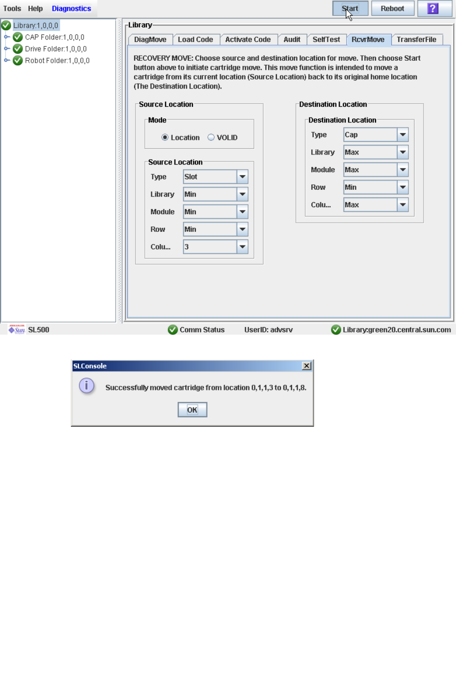
Cartridge Management Tasks
96 SL500 User’s Guide • July 2008 Revision: KA • 96116
8. Click the Start button in the Options Bar.
The robot moves the cartridge, and then a success message popup appears.
9. Click OK.
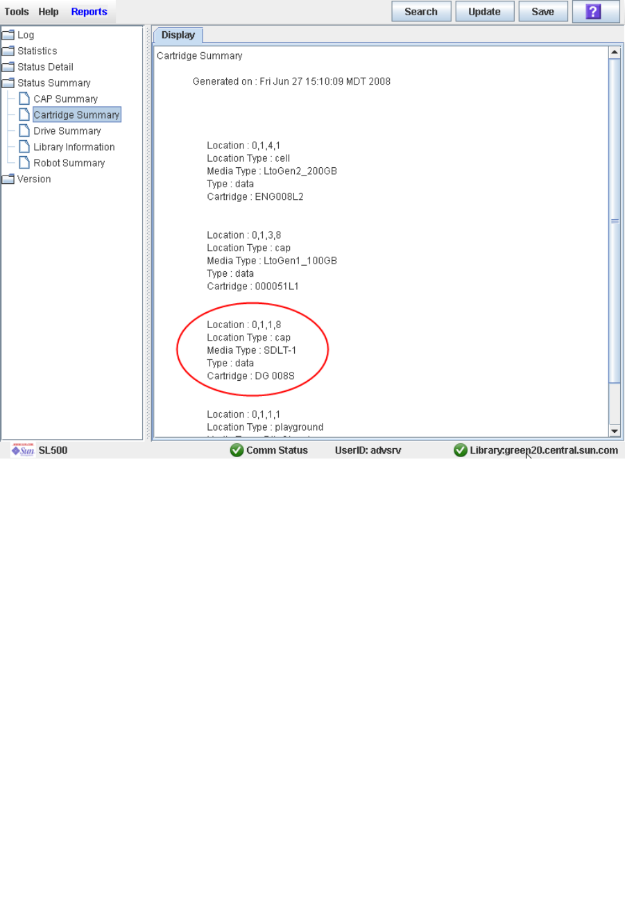
Cartridge Management Tasks
96116 • Revision: KA Chapter 3 SL500 Automated Library Operations 97
10.To verify the new location, you can display a Cartridge Summary Report. See “List
Library Cartridges” on page 88 for details. For example:
11.To update the new cartridge location in the host database, initiate a library audit
from the host software. See the appropriate tape management software
documentation for the procedures and commands.

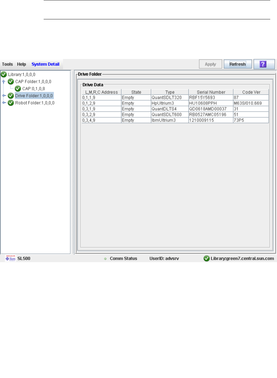
Drive Management Tasks
96116 • Revision: KA Chapter 3 SL500 Automated Library Operations 99
▼ Display Drive Summary Information
Use this procedure to display summary information for all drives in the library.
If you need to perform a manual mount to a drive, this procedure displays a mapping
of all addresses for each library drive:
Note – This information is also available through Reports > Drive Summary. See
“Display a Library Report” on page 74 for detailed instructions.
1. Select Tools > System Detail.
2. Click the Drive folder on the device tree.
The screen lists the library drives and displays their locations.
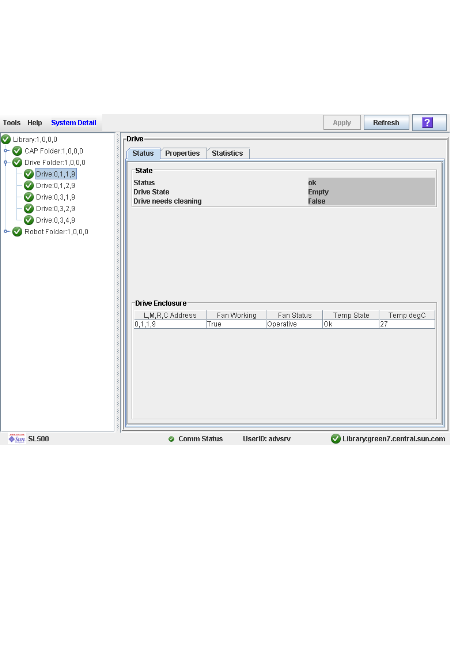
Drive Management Tasks
100 SL500 User’s Guide • July 2008 Revision: KA • 96116
▼ Display Drive Status
Use this procedure to display the current operational state of a drive.
Note – This information is also available through Reports > Drive Details. See
“Display a Library Report” on page 74 for detailed instructions.
1. Select Tools > System Detail.
2. Expand the Drive Folder, and click the drive you want to display.
3. Click Status.
The screen displays the current status of the selected drive.
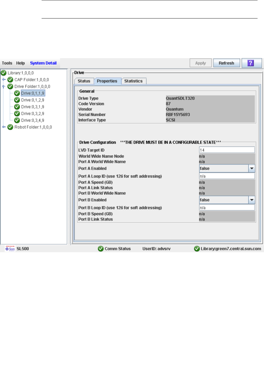
Drive Management Tasks
96116 • Revision: KA Chapter 3 SL500 Automated Library Operations 101
▼ Display Drive Properties
View detailed drive configuration information, including the drive type and serial
number and port configuration.
Note – This information is also available through Reports > Drive Details. See
“Display a Library Report” on page 74 for detailed instructions.
1. Select Tools > System Detail.
2. Expand the Drive Folder, and click the drive you want to display.
3. Click Properties.
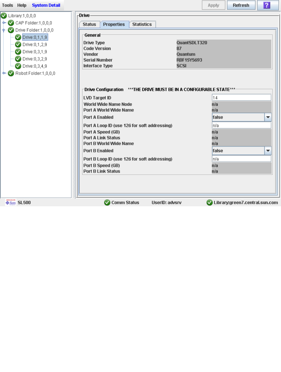
Drive Management Tasks
102 SL500 User’s Guide • July 2008 Revision: KA • 96116
▼ Enable or Disable a Drive Port
Use this procedure to enable or disable a physical port on a drive.
1. Select Tools > System Detail.
2. Expand the Drive Folder, and click the drive you want to modify.
3. Click Properties.
4. Set the Port A Enabled or Port B Enabled status as follows:
■True—Turns on the port.
■False—Turns off the port; the communication channel between the host software and
the drive is disabled.
5. The network software automatically configures the Port (A or B) address. This is
called soft mode addressing.
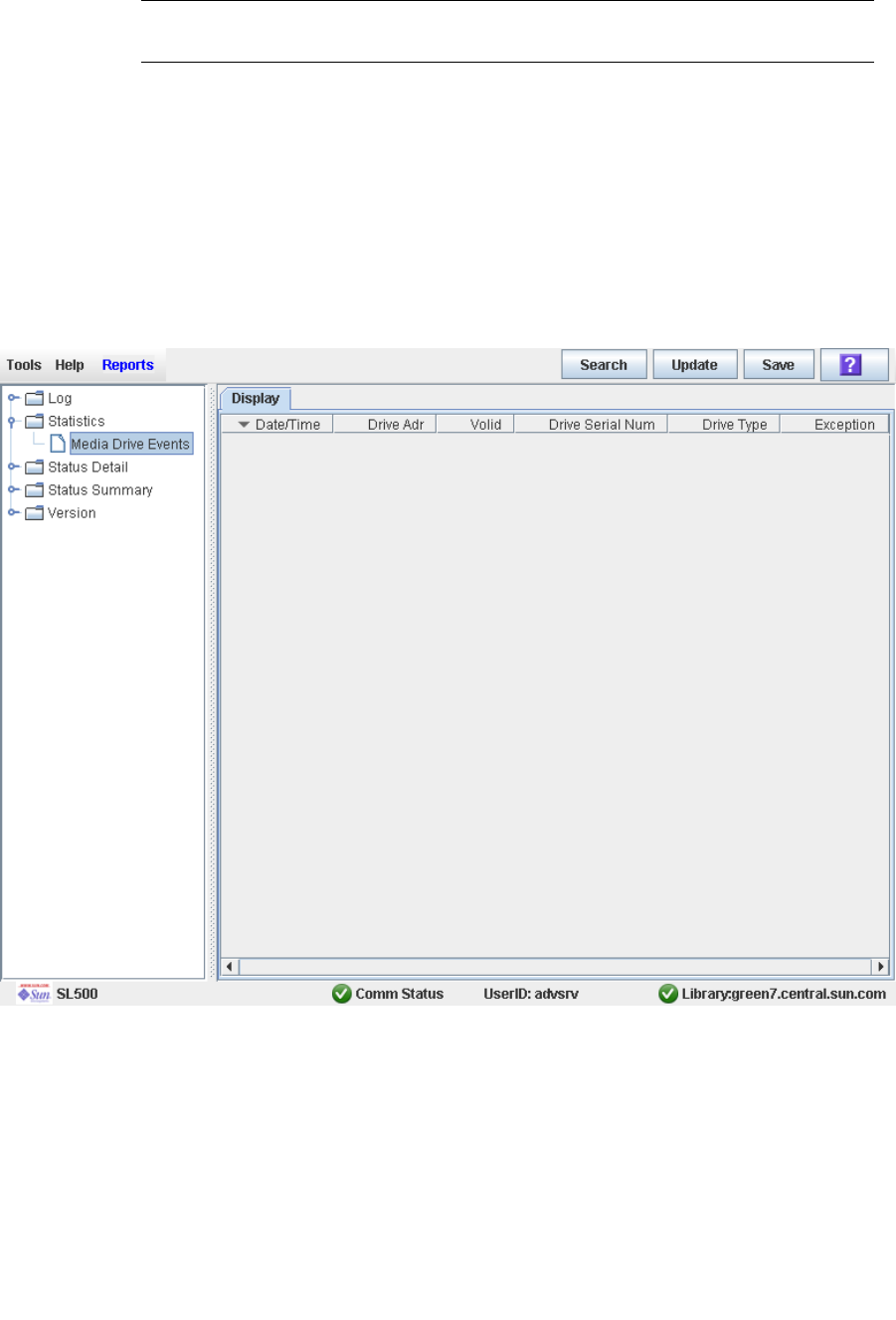
Drive Management Tasks
96116 • Revision: KA Chapter 3 SL500 Automated Library Operations 103
▼ Display the Media Drive Events Report
Note – This feature is available starting with SL500 firmware version 1200 and
SL Console version 3.30.
The Media Drive Events Report lists the 100 most recent library media access errors.
The report is updated whenever a drive is not able to perform a load, unload, read, or
write operation on a cartridge. You can use the report to help determine whether a
particular drive or cartridge is in need of maintenance or replacement.
By default, the report is sorted in reverse chronological order (that is, by Date/Time,
with the most recent entry at the top). Optionally, you can change the sort order, and
rearrange and resize the columns. See “Modifying the Screen Layout” on page 32.
1. Select Tools > Reports.
2. Expand the Statistics folder, and click Media Drive Events.
Screen Fields
Date/Time
Date and time the error occurred.

Drive Management Tasks
104 SL500 User’s Guide • July 2008 Revision: KA • 96116
Drive Adr
Location of the drive involved in the error. Format is l.m.r.c, where:
■l = library ID
■m = module ID
■r = row ID
■c = column ID
Volid
VOLID of the cartridge involved in the error.
Drive Serial Num
Serial number of the drive involved in the error.
Drive Type
Type of drive. For example, Hewlett-Packard LTO Ultrium 2 or Quantum SDLT 320.
Exception
Type of error. Options are:
■LoadError—The drive load failed after all retries were attempted. See LoadRetry
for an explanation of the retry conditions.
■LoadRetry—The drive load was successful, but required one or more retries,
which involve removing and reinserting the cartridge and reissuing a load
command to the drive. A retry is initiated if either the cartridge is not detected as
sensed from the drive (except DLT drives), or the load command to the drive fails.
■MediaError—The drive signaled a media error during drive load or unload. IBM
drives allow cartridges with media errors to be loaded, while Hewlett-Packard
drives do not.
■UnloadError—The library could not successfully unload and remove the cartridge
from the drive.

Drive Cleaning Tasks
96116 • Revision: KA Chapter 3 SL500 Automated Library Operations 105
Drive Cleaning Tasks
Task Page
Configure Drive Auto Clean 106
Enter Cleaning or Diagnostic Cartridges 107
Eject Cleaning or Diagnostic Cartridges 109
Display Cleaning Cartridges 111
Display Drive Cleaning Status 112
Clean a Drive Manually 113
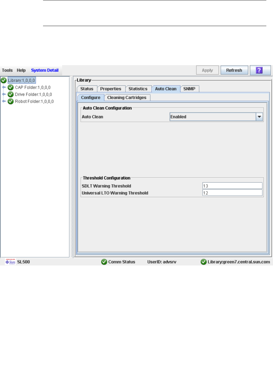
Drive Cleaning Tasks
106 SL500 User’s Guide • July 2008 Revision: KA • 96116
▼ Configure Drive Auto Clean
Use this procedure to enable or disable the drive auto clean feature. If the library is
partitioned, auto clean can be enabled or disabled for individual partitions.
Note – This procedure applies only to drives that are not managed by HSC or ACSLS.
See the HSC and ACSLS documentation for details about how they manage automatic
cleaning operations.
1. Select Tools > System Detail, and select the library folder on the device tree.
2. Click Auto Clean and then Configure.
The Configure Auto Clean screen appears.
3. Set the Auto Clean field to Enabled.
4. In the Threshold Configuration section, specify the warning thresholds for each
cartridge type.
5. Click Apply.
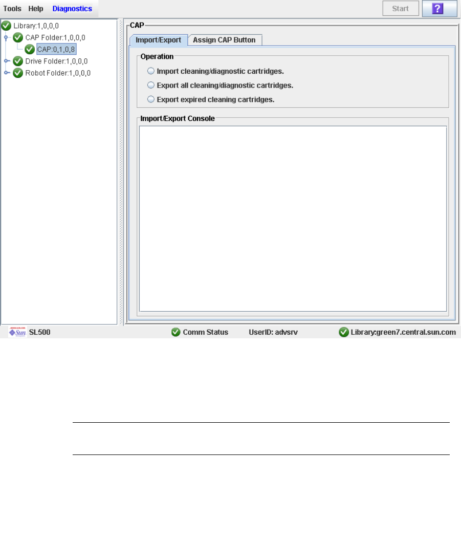
Drive Cleaning Tasks
96116 • Revision: KA Chapter 3 SL500 Automated Library Operations 107
▼ Enter Cleaning or Diagnostic Cartridges
Use this procedure to enter new cleaning or diagnostic cartridges to the library through
a CAP. The cartridges will be inserted into system cells.
Before beginning this procedure, verify that all the following conditions are met:
■The required number of reserved cells are empty.
■The CAP Prevent/Allow state is set to Allow (see your SCSI Reference Manual for
syntax).
■The CAP does not contain any data cartridges.
1. Select Tools > Diagnostics.
2. Expand the CAP Folder, highlight the CAP and then select the Import/Export tab.
3. Select “Import Cleaning/Diagnostic cartridges” and then select the Start button from
the Options Bar.
4. The library controller opens the CAP door and the CAP Open LED is turned on.
5. Grip the handle of the magazine and slide it out of the CAP and onto the door.
Note – To help slide the magazine back into the CAP, do not remove the magazine
from the door. Instead, leave the magazine on the CAP door rails.

Drive Cleaning Tasks
108 SL500 User’s Guide • July 2008 Revision: KA • 96116
6. Place the cartridges into the empty magazine cells, making sure that the VOLID label
is visible and the hub of the cartridge is down.
Caution – Possible damage to components. You must enter the cartridges properly, or
else you might damage the HandBot or the drive or cause the library to stop operating.
Use only cartridges designed for the drives in your library.
7. Grip the handle and slide the magazine back into the CAP.
8. Close the CAP door making sure that the door is securely latched.
The HandBot systematically moves each cleaning and diagnostic cartridge from the
CAP to an empty reserved cell.
9. Monitor the Import/Export Console to verify the status of the import operation.
The “Operation completed” status indicates that the import cartridge operation is
completed.
10.After the import operation is complete, the HandBot audits the CAP.
To view a list of cleaning and diagnostic cartridges in the reserved cells, see “Display
Cleaning Cartridges” on page 111.
Note – If you want to import cleaning and diagnostic cartridges into reserved cells one
cartridge at a time, use the Recovery Move diagnostic utility. See “Move a Cartridge
From a Specified Location” on page 93.
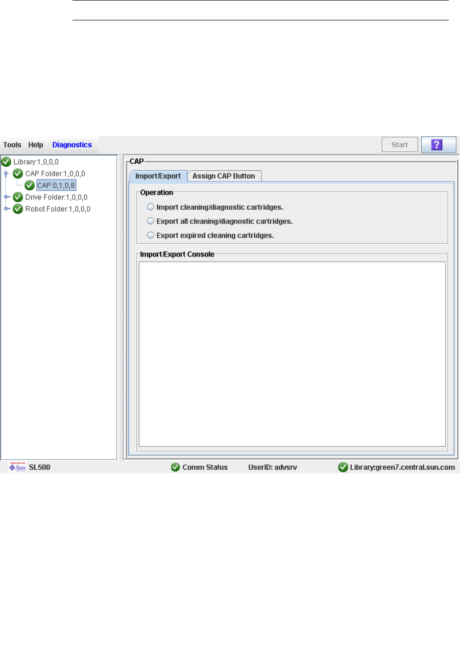
Drive Cleaning Tasks
96116 • Revision: KA Chapter 3 SL500 Automated Library Operations 109
▼ Eject Cleaning or Diagnostic Cartridges
Use this procedure to eject expired cleaning or diagnostic cartridges through the CAP.
Note – Before beginning this procedure, verify that the CAP cells are empty.
You must use care when ejecting expired cleaning cartridges from the library. If you
move an expired cleaning cartridge to a CAP and open the CAP, you must remove the
cartridge. If you close the CAP without removing the cleaning cartridge first, the
HandBot will re-enter the expired cartridge into the library, and the library controller
will reset the usage count to zero.
1. Select Tools > Diagnostics.
2. Expand the CAP Folder, highlight the CAP and then select the Import/Export tab.
3. Do one of the following:
■To export only the expired cleaning or diagnostic cartridges, select the “Export
expired cleaning/diagnostic cartridges” option.
■To export all cartridges from the reserved cells that include the cleaning and
diagnostic cartridges select the “Export all cleaning/diagnostic cartridges” option.
4. Select the Start button from the upper right corner of the screen.

Drive Cleaning Tasks
110 SL500 User’s Guide • July 2008 Revision: KA • 96116
If you selected the “Export expired cleaning/diagnostic cartridges” option, the
HandBot systematically moves all expired cleaning and diagnostic cartridges from the
reserved cells into empty CAP cells.
If you selected the “Export all cleaning/diagnostic cartridges” option, the HandBot
moves all cleaning and diagnostic cartridges from the reserved cells into empty CAP
cells.
5. The library controller opens the CAP and the CAP Open LED turns on.
6. Grip the handle of the magazine and slide it out of the CAP and onto the door.
Note – To help slide the magazine back into the CAP, do not remove the magazine
from the door. Instead, leave the magazine on the CAP door rails.
7. Remove the cartridges from the magazine.
8. Grip the handle and slide the magazine back into the CAP.
9. Close the CAP door making sure that the door is securely latched.
10.Monitor the Import/Export Console to verify the status of the export operation.
The “Operation completed” status indicates that the export cartridge operation is
completed.
Note – If you want to export cleaning or diagnostic cartridges in reserved cells one at
a time use the Recovery Move diagnostic utility. See “Move a Cartridge From a
Specified Location” on page 93.
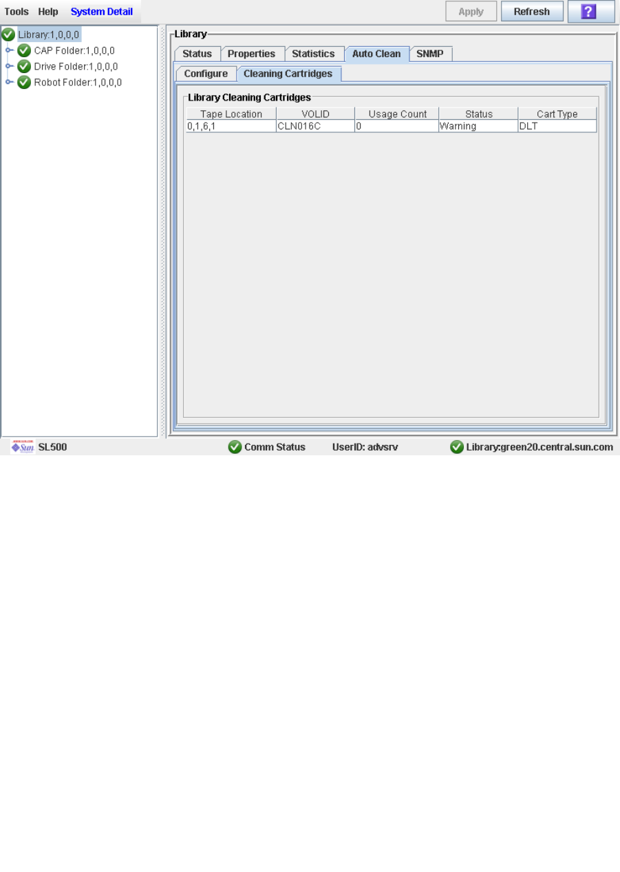
Drive Cleaning Tasks
96116 • Revision: KA Chapter 3 SL500 Automated Library Operations 111
▼ Display Cleaning Cartridges
1. Select Tools > System Detail, and select the library folder on the device tree.
2. Click Auto Clean and then Cleaning Cartridges.
The list displays the following details for each cleaning cartridge:
■Cartridge location (reserved cells)
■VOLID
■Usage Count
■Status (OK, warning, expired)
■Cartridge Type (for example, LTO, SDLT)
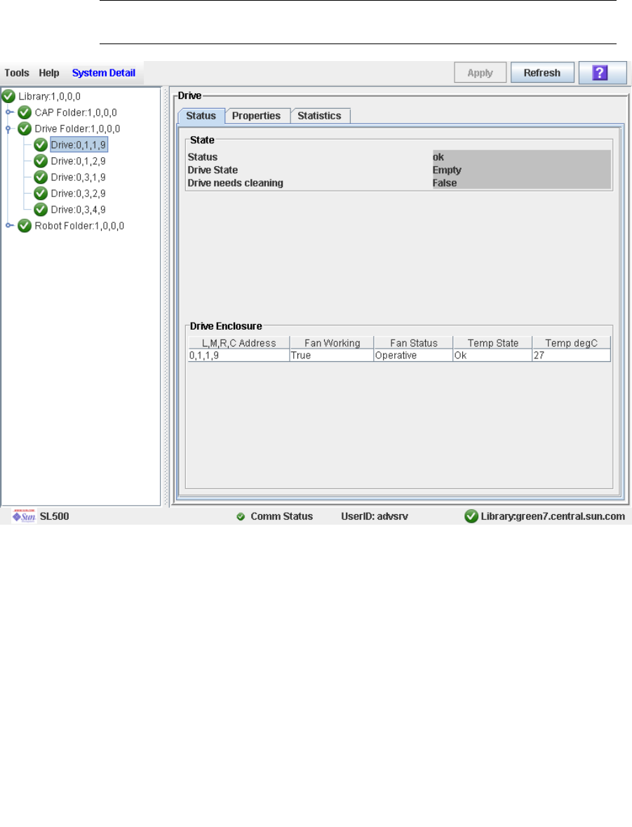
Drive Cleaning Tasks
112 SL500 User’s Guide • July 2008 Revision: KA • 96116
▼ Display Drive Cleaning Status
Use this procedure to display the current cleaning status of a drive.
1. Select Tools > System Detail.
2. Expand the Drive Folder, and select the drive you want to display.
3. Click Status.
Note – You can schedule manual drive cleaning by monitoring the “Drive needs
cleaning” status.
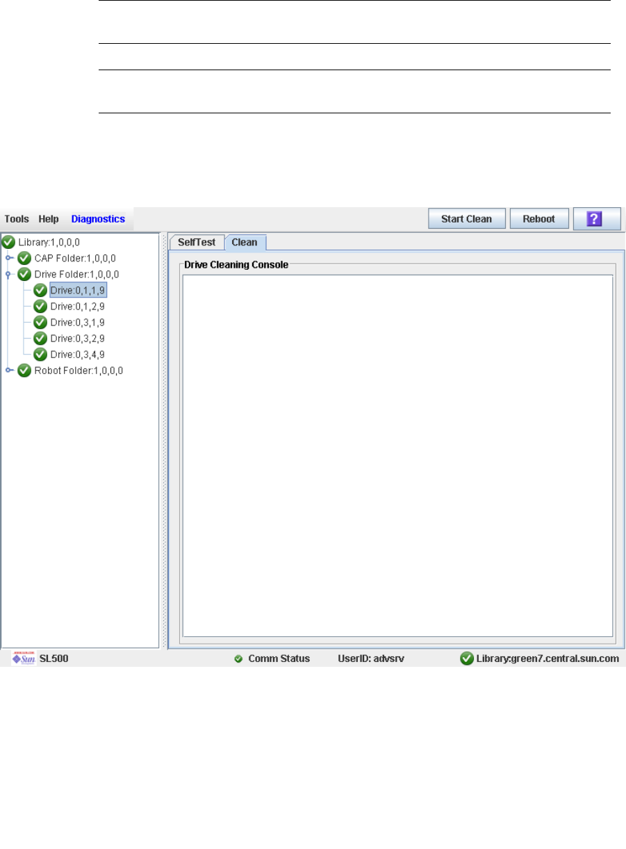
Drive Cleaning Tasks
96116 • Revision: KA Chapter 3 SL500 Automated Library Operations 113
▼ Clean a Drive Manually
Your library could contain more than one type of drive. So, before initiating a clean job,
make sure that the system cells have the appropriate cleaning cartridges for the drives
being cleaned. Generate a cartridge summary and drive details report to verify the
cleaning cartridges present in the library.
Note – To display a list of cleaning cartridges, see “Display Cleaning Cartridges” on
page 111.
Note – You can initiate a manual clean even if the “drive needs cleaning” status is
“false.”
1. Select Tools > Diagnostics.
2. Expand the Drive Folder.
3. Select the drive that requires cleaning and then select the Clean tab.
4. Click the Start Clean button in the Options Bar.
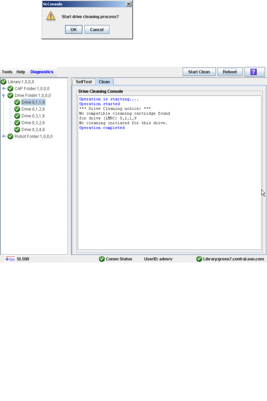
Drive Cleaning Tasks
114 SL500 User’s Guide • July 2008 Revision: KA • 96116
A confirmation popup appears.
5. Click OK.
6. The Drive Clean Status Console displays the status of the cleaning operation.

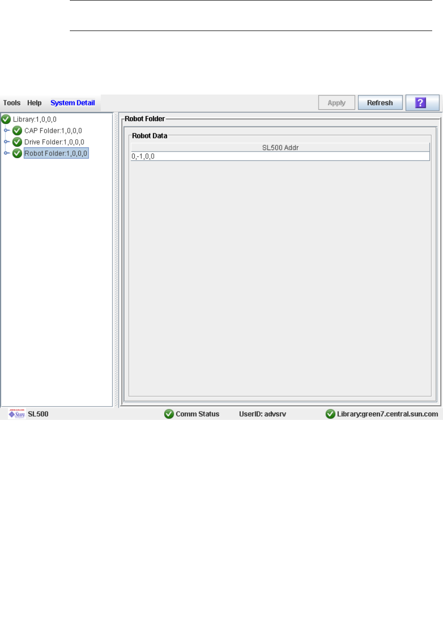
Robot Monitoring Tasks
116 SL500 User’s Guide • July 2008 Revision: KA • 96116
▼ Display Robot Summary Information
Use this procedure to display summary information for the library HandBot.
Note – This information is also available through Reports > Robot Summary. See
“Display a Library Report” on page 74 for detailed instructions.
1. Select Tools > System Detail.
2. Click the Robot folder on the device tree.
The Robot Data screen appears.
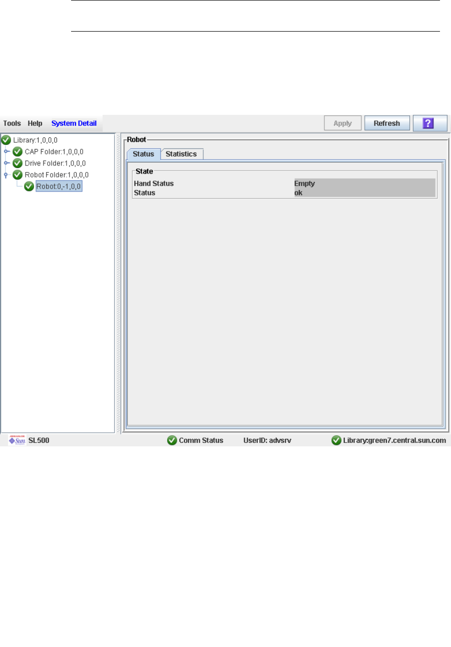
Robot Monitoring Tasks
96116 • Revision: KA Chapter 3 SL500 Automated Library Operations 117
▼ Display Robot Status
Use this procedure to display the current operational state of a HandBot.
Note – This information is also available through Reports > Robot Details. See
“Display a Library Report” on page 74 for detailed instructions.
1. Select Tools > System Detail.
2. Expand the Robot Folder, and click the robot.
3. Click Status.
The screen displays the current status of the HandBot.
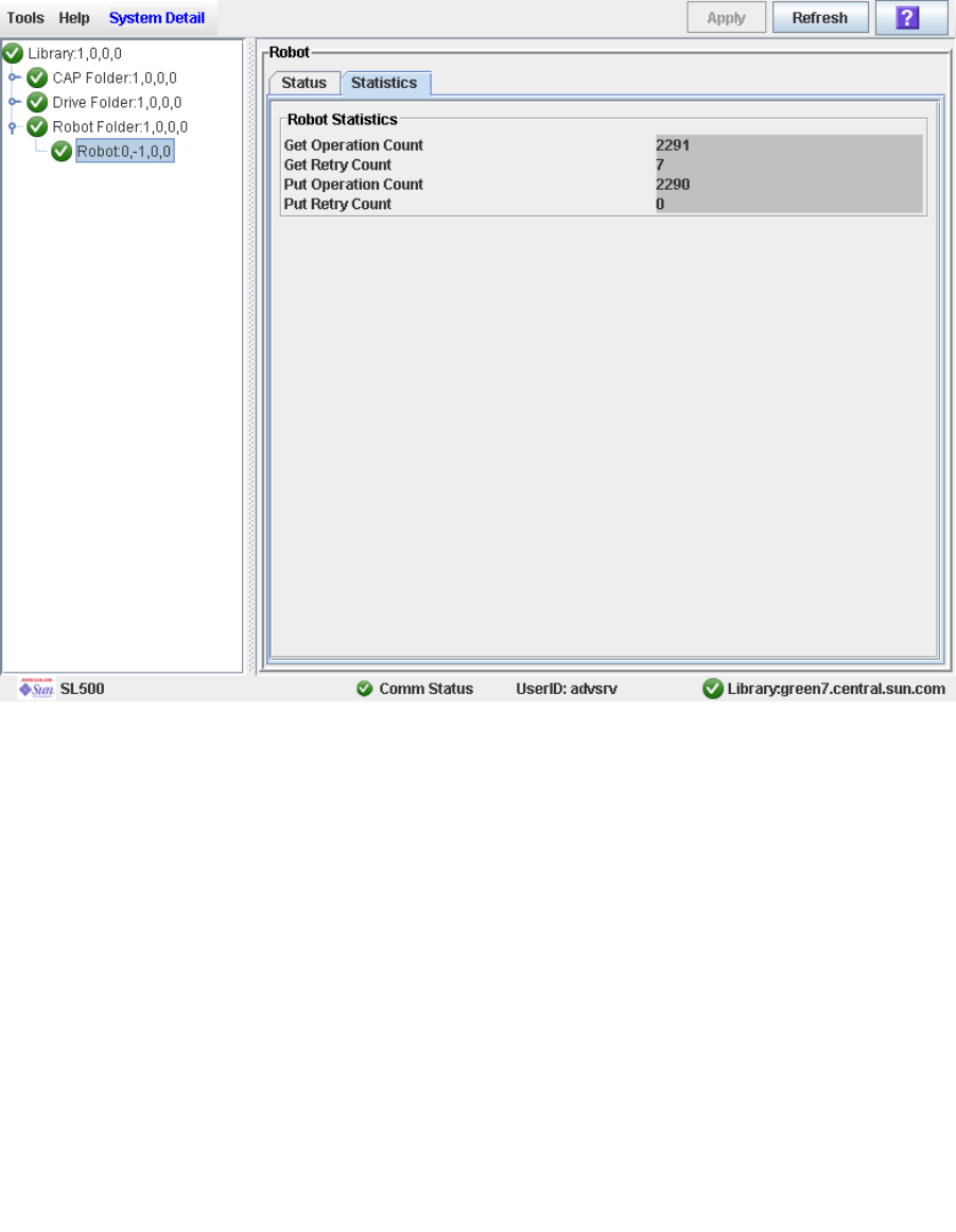
Robot Monitoring Tasks
118 SL500 User’s Guide • July 2008 Revision: KA • 96116
▼ Display Robot Statistics
Use this procedure to display HandBot statistics, including Get, Put, and Retry counts.
1. Select Tools > System Detail.
2. Expand the Robot Folder, and click the robot.
3. Click Statistics.
The Robot Statistics screen appears.

96116 • Revision: KA 119
CHAPTER 4
Licensing
The licensing utility allows you to install selected optional features on the SL500
library.
Note – The Licensing utility is available starting with SL500 firmware version 1300 and
SL Console version FRS_4.00.
License Key File
A license key file can be delivered to you in the following ways:
■Via e-mail from Sun Microsystems, Inc.
■Installed by your Sun support representative
The license key file is a digitally signed image (.img) file containing one or more
license keys for features you have purchased. In order to ensure that features are
installed on the correct library, the license key file includes the serial number of the
target library and can only be installed on that library.
Each license key file is assigned a unique sequence number. The sequence number
ensures that only one instance of a license key file can be installed on a library at a time.
SL500 licenses are cumulative. When you install a new license key file, the included
features are added to the features already installed on the library.
SL500 licenses currently do not expire.

Licensing Tasks
120 SL500 User’s Guide • July 2008 Revision: KA • 96116
Licensing Tasks
This section provides detailed instructions for all tasks involved in installing and
managing library feature licenses.
License Installation Process
Following is a summary of the license installation process. Optionally, you can choose
to have this process done by your Sun support representative.
1. You purchase one or more features for a specific Sun StorageTek library from Sun
Microsystems, Inc.
2. Sun sends you an e-mail with an attached license key file.
3. You download the license key file to a system accessible to the SL Console session.
4. You use the SL Console to verify and install the license key file on the target library.
5. You reboot the library in order to activate the new features.
6. See the following topics for detailed information about implementing specific
licensed features:
■“Capacity on Demand” on page 147
■“Library Partitioning” on page 143


Licensing Tasks
122 SL500 User’s Guide • July 2008 Revision: KA • 96116
▼ Receive a New License Key File
Use this procedure to receive a license key file, which licenses features for a specific
Sun StorageTek library.
Note – This procedure is not performed at the SL Console.
1. Purchase one or more features from Sun Microsystems, Inc.
See your Sun support representative for assistance.
2. Receive the license key file from Sun, via e-mail.
Following is a sample of the e-mail header:
Subject: SL500 License Key CR6636975
Date: Wed, 23 Apr 2008 19:24:41 -0700 (MST)
From: Do_Not_Reply_SILKS@sun.com
3. Download the license key file to a system accessible to the SL Console session.
Use the standard method for saving e-mail attachments.
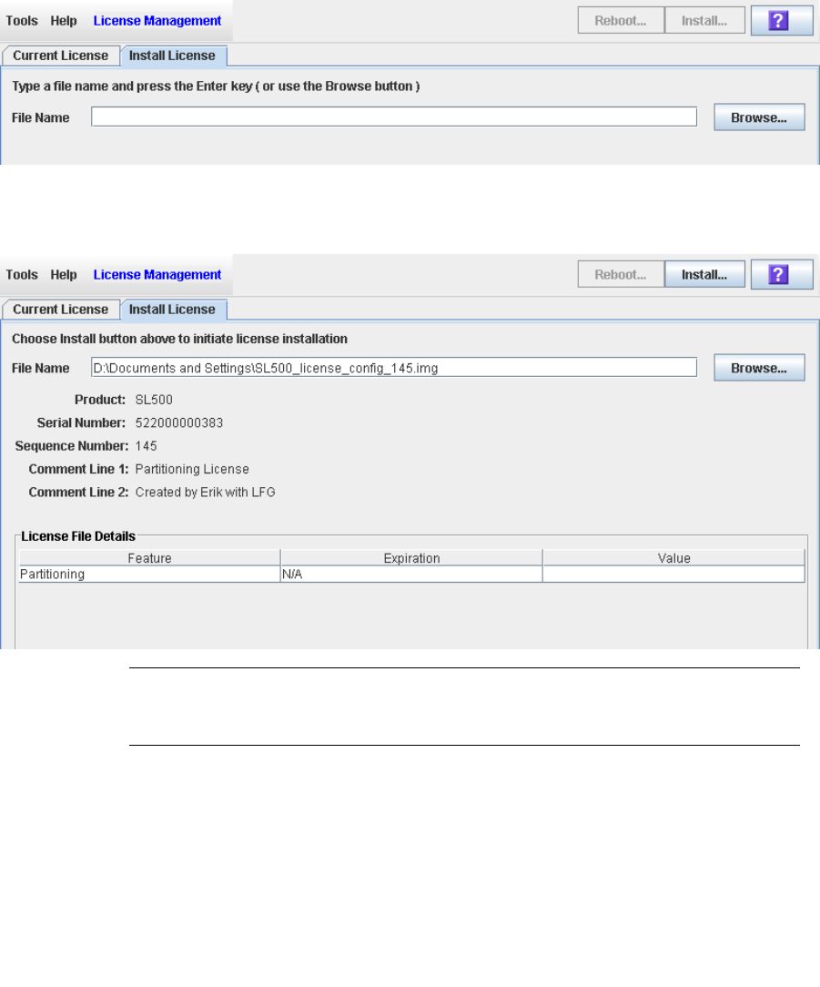
Licensing Tasks
96116 • Revision: KA Chapter 4 Licensing 123
▼ Install a New License on the Target Library
Use this procedure to install a new license key file on the target library.
Prior to performing this procedure, you must download a new license key file to a
system accessible to the SL Console session. See “Receive a New License Key File” on
page 122.
1. Use the SL Console to log in to the target library.
See “Log in to the SL Console” on page 29 for details.
2. Select Tools > License Management, and click the Install License tab.
The Install License screen appears.
3. In the File Name field, enter the full path of the license key file you want to install,
and press Enter. Optionally, you can click Browse and navigate to the file location.
The License File details appear in the lower part of the screen.
Note – If the library serial number in the specified license key file does not match the
serial number of the library you are logged in to, a warning appears and the license key
file detail is not displayed.
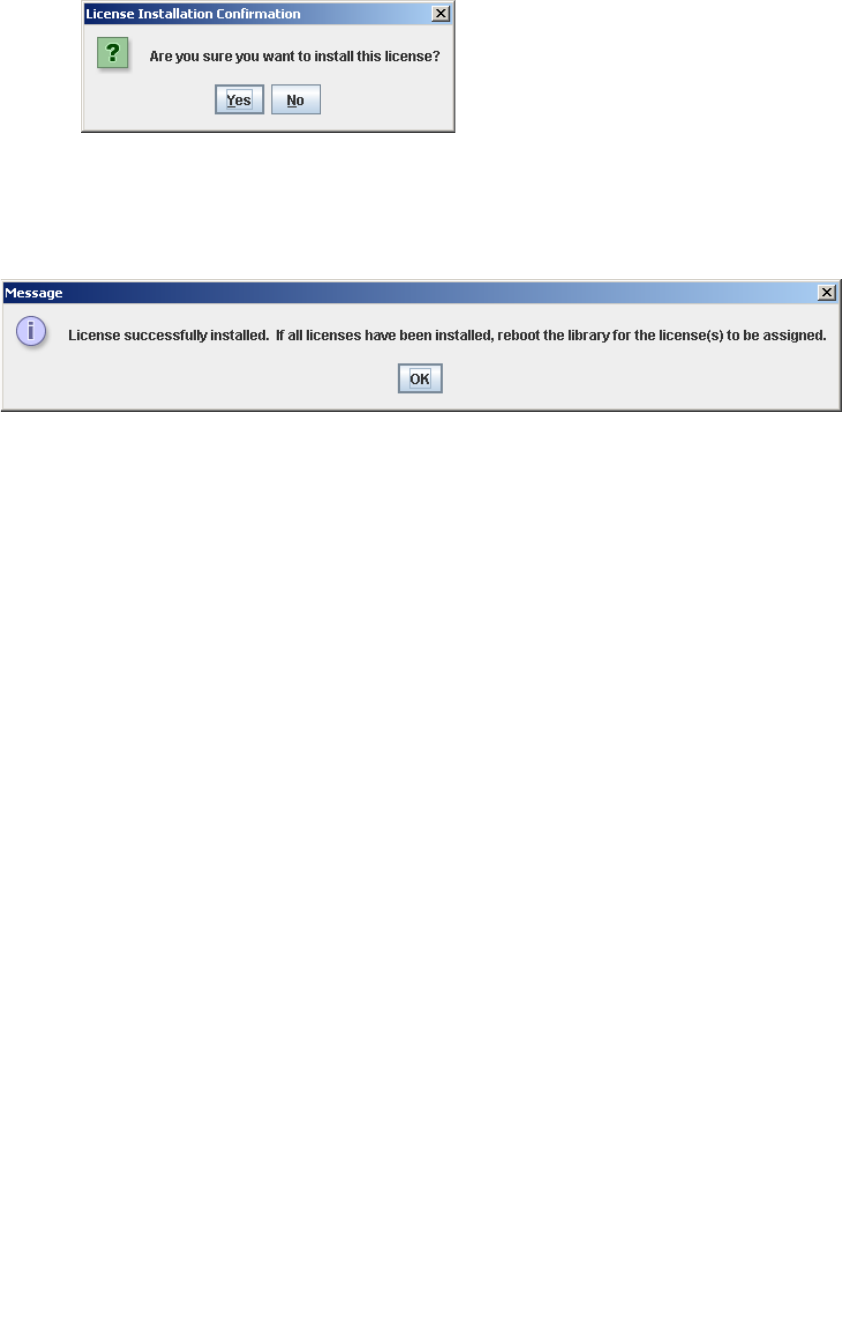
Licensing Tasks
124 SL500 User’s Guide • July 2008 Revision: KA • 96116
4. Review the license key file details, and then click Install in the Options Bar.
The License Installation Confirmation popup appears.
5. Click Yes to begin installing the license on the target library.
6. The library controller verifies the license key file and proceeds as follows:
■If there are no problems, the features included in the file are installed.
■A confirmation popup appears. Click OK to dismiss the popup.
7. You must reboot the library in order for the new license features to be activated.
Click the Reboot button in the Options Bar. See “Reboot the Library” on page 268 for
detailed instructions.
8. You can verify that the license has been installed and activated successfully by
displaying the current licenses. See “Display Current Library Licenses” on page 125
for details.
9. Depending on the features included in the license key file, you may need to perform
additional tasks in order to use the new features.
■See “Increasing Licensed Capacity” on page 150 for special considerations that apply
when you install a license key file that adds licensed capacity to the library.
■See “Installing the Partitioning Feature” on page 145 for special considerations that
apply when you install a license key file with the Partitioning feature.
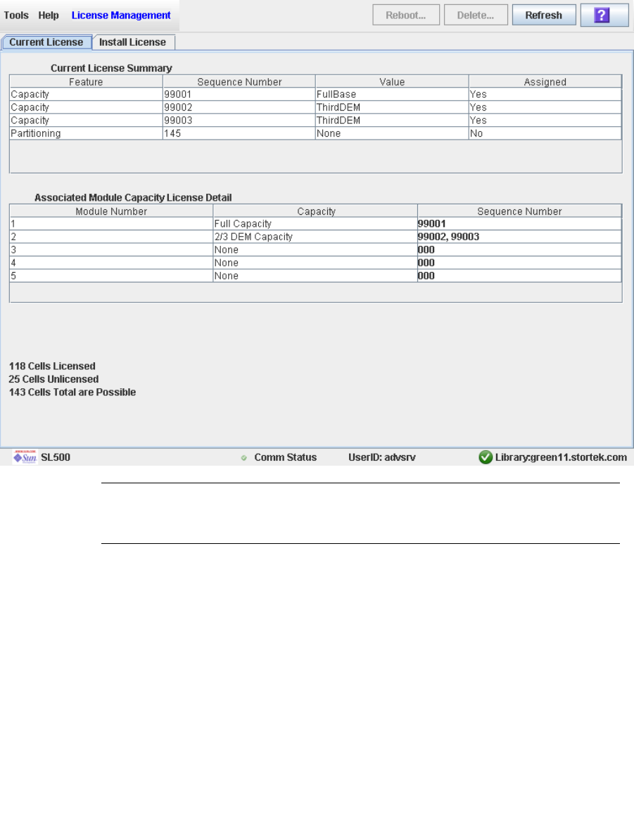
Licensing Tasks
96116 • Revision: KA Chapter 4 Licensing 125
▼ Display Current Library Licenses
Use this procedure to display the features currently installed on the library you are
logged in to.
1. Select Tools > License Management, and click the Current License tab.
The Current License screen appears, listing the currently installed features. See
“License Management > Current License” on page 130 for detailed information about
the screen fields.
Note – If a feature has been installed, but the library has not yet been rebooted, the
Assigned column will indicate “No”. The library must be rebooted in order for the
feature to be activated.

Licensing Tasks
126 SL500 User’s Guide • July 2008 Revision: KA • 96116
▼ Delete a License Key File
Use this procedure to delete a license key file from an SL500 library.
You may need to delete a license key file if there is an error in an installed file. Sun will
issue a new license key file with the same sequence number as the original, and you
must delete the original license key file before installing the new one.
Caution – Deleting a license key file is an exceptional situation. Be sure it is what you
really want to do before you begin this procedure. Having extra license key files
installed on a library does not present any problems (for example, Capacity licenses
that exceed the physical capacity of the library); the extra licenses are simply not used.
Caution – Deleting a Capacity license key file reduces the licensed capacity of the
affected library module. This can result in orphaned cartridges and data that could be
lost. See “Decreasing Licensed Capacity” on page 141 and “Orphaned Cartridges in
Non-Partitioned Libraries” on page 140 for details.
Caution – Deleting a Partitioning license key file deletes the Partitioning feature from
the library. See “Deleting the Partitioning Feature” on page 148 for details about the
effects on the library configuration.
1. Use the SL Console to log in to the target library.
See “Log in to the SL Console” on page 29 for details.
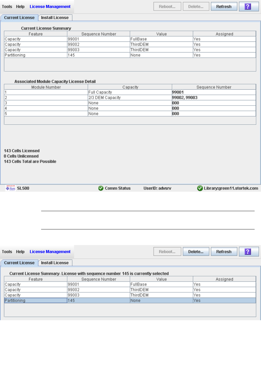
Licensing Tasks
96116 • Revision: KA Chapter 4 Licensing 127
2. Select Tools > License Management, and click the Current License tab.
The Current License screen appears, listing the currently installed features.
3. Click the license you want to delete.
Note – Sequence numbers 99000 and above are permanently retained and cannot be
deleted from the library.
The Delete button in the Options Bar is activated.
4. Click the Delete button.
Depending on the type of license you are deleting, one of the following Delete
Confirmation popups appears.
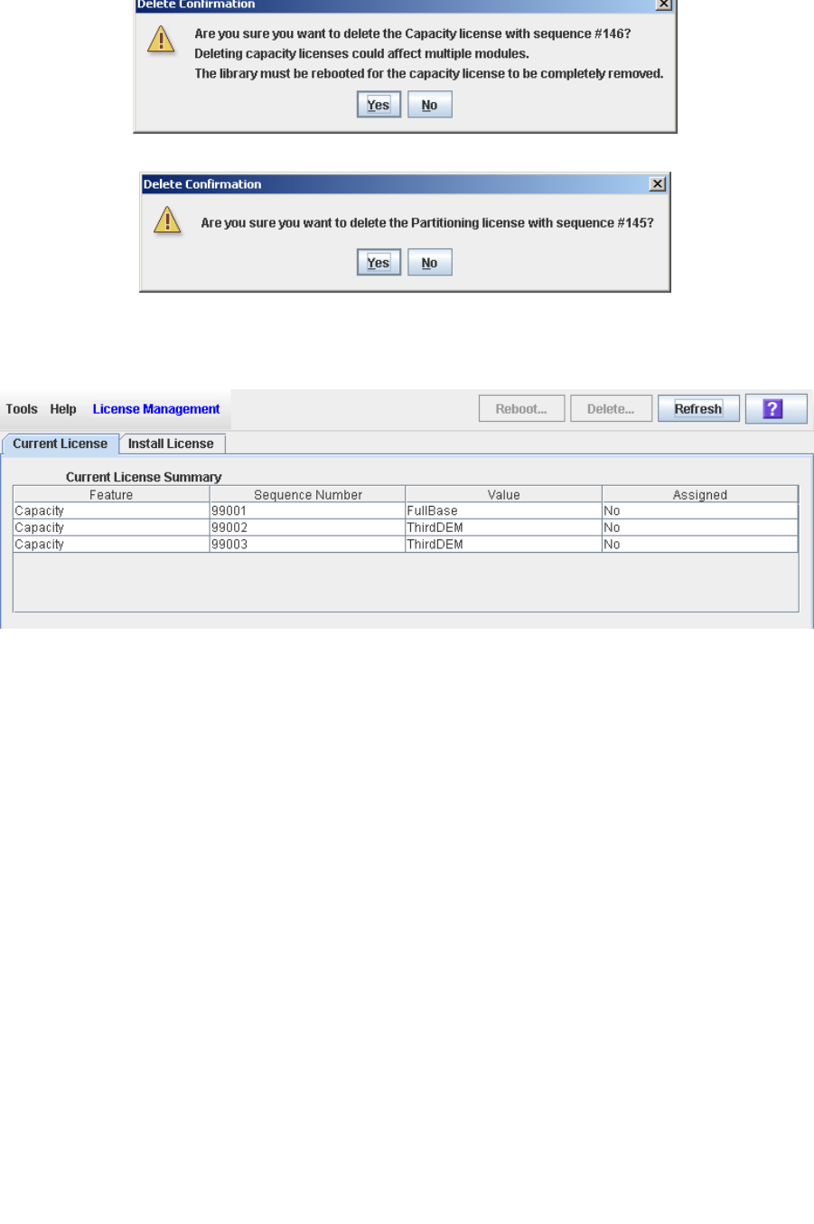
Licensing Tasks
128 SL500 User’s Guide • July 2008 Revision: KA • 96116
■For Capacity licenses:
■For Partitioning licenses:
5. Click Yes to begin the deletion.
The license key file is deleted from the library, and the Current License Summary is
updated.
6. You must reboot the library in order for the license deletion to take effect. See
“Reboot the Library” on page 268 for detailed instructions.
7. Depending on the feature included in the license key file, you may need to perform
additional tasks after deleting the file.
■See “Decreasing Licensed Capacity” on page 151 for special considerations that
apply when you delete a Capacity license key file.
■See “Deleting the Partitioning Feature” on page 148 for special considerations that
apply when you delete a Partitioning license key file.

Licensing Screen Reference
96116 • Revision: KA Chapter 4 Licensing 129
Licensing Screen Reference
This section includes detailed descriptions of all SL Console licensing screens, arranged
by screen navigation path. For example, License Management > Install License
indicates the screen accessed by clicking Tools and then License Management from the
Menu Bar, and then clicking the Install License tab.
Note – You can access the licensing screens only from the standalone SL Console or the
Web-launched SL Console. They are not available on the local operator panel.
Screen Page
License Management > Current License 130
License Management > Install License 133
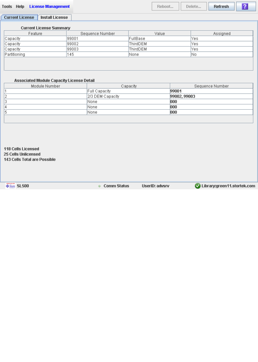
Licensing Screen Reference
130 SL500 User’s Guide • July 2008 Revision: KA • 96116
License Management > Current License
Sample Screen
Description
Displays the contents of all license key files currently installed on the library you are
logged in to.
You can modify the layout and display of this screen. See “Modifying the Screen
Layout” on page 32 for details.
Screen Fields
Current License Summary
Feature
Display only.
Name of the feature installed on the library.

Licensing Screen Reference
96116 • Revision: KA Chapter 4 Licensing 131
Sequence Number
Display only.
Unique sequence number assigned to the license key file by Sun Microsystems, Inc.
Note – Sequence numbers 99000 and above are permanently retained and cannot be
deleted from the library.
Value
Display only.
Qualification for the feature, if applicable. For example, for the Capacity feature, this
field displays the capacity the license provides, such as “FullBase”, “ThirdDEM”, etc.
Depending on the feature, the field may be blank or indicate “None”.
Assigned
Display only.
Indicates whether the feature is currently activated on the library. Options are:
■Yes—Feature has been activated
■No—Feature has been installed, but not activated; the library must be rebooted in
order for the feature to be activated.
Associated Module Capacity License Detail
Module Number
Display only.
Numeric module ID. Possible values are 1–5.
Capacity
Display only.
Total module capacity that has been licensed for use. Possible values are:
■Full Capacity—All storage cells in the module are licensed for use.
■None—No storage cells in the module have been licensed for use. May also
indicate that the module is not installed in the library.
■1/3 Capacity—One-third of the storage cells in the module have been licensed.
Applies only to the DEM.
■2/3 Capacity—Two-thirds of the storage cells in the module have been licensed.
Applies only to the DEM.
Sequence Number
Display only.
License key file sequence numbers used in providing the indicated capacity. If more
than one license key file is involved, the sequence numbers are separated by
commas.
000 indicates no license key file has been installed for the module.
nnn Cells Licensed
Display only.

Licensing Screen Reference
132 SL500 User’s Guide • July 2008 Revision: KA • 96116
Total number of storage cells in the library that have been licensed for use. This
cannot be greater than the physical capacity of the library.
nnn Cells Unlicensed
Display only.
Total number of storage cells in the library that have not been licensed for use.
nnn Cells Total are Possible
Display only.
Total physical capacity of the library.
Buttons
Reboot
Click to reboot the library.
Delete
Click to delete the selected license key file from the library.
Refresh
Click to refresh the display with current data from the library controller database.
? (Help)
Click to display online help for the screen.
See Also
■License Management > Install License
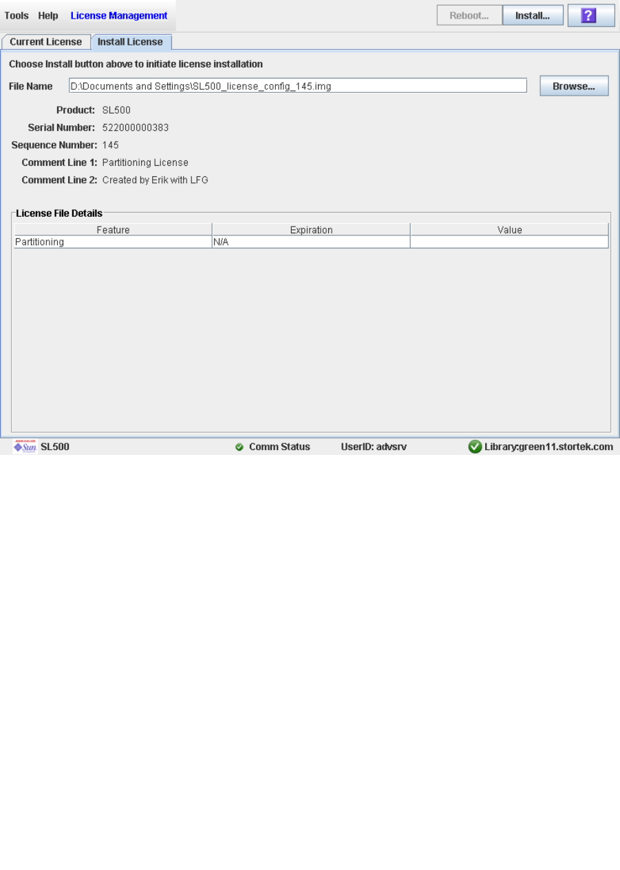
Licensing Screen Reference
96116 • Revision: KA Chapter 4 Licensing 133
License Management > Install License
Sample Screen
Description
Allows you to display the contents of a new license key file and install it on the library.
You can modify the layout and display of this screen. See “Modifying the Screen
Layout” on page 32 for details.
Screen Fields
File Name
Required.
Enter the full path of the license key file you want to install on the library.
Optionally, you can click Browse and navigate to the file location. The file must be
located on a system accessible to the SL Console session, and the serial number
specified in the file must match the serial number of the library you are logged in to.

Licensing Screen Reference
134 SL500 User’s Guide • July 2008 Revision: KA • 96116
Product
Display only.
Type of library the license key file is for. For example, SL3000, SL8500, SL500.
Serial Number
Display only.
Serial number of the library the license key file is for. This entry must match the
serial number of the library you are logged in to in order for the license key file to be
valid for this library.
Sequence #
Display only.
Unique sequence number assigned to the license key file by Sun Microsystems, Inc.
Note – Sequence numbers 99000 and above are permanently retained and cannot be
deleted from the library.
Comment Line 1
Display only.
Optional comment concerning the license key file, from Sun Microsystems, Inc.
Comment Line 2
Display only.
Optional comment concerning the license key file, from Sun Microsystems, Inc.
License File Details
Feature
Display only.
Name of a feature included in the license key file.
Expiration
Display only.
Number of days until the feature is due to expire. Because SL500 library features do
not expire, the value for this field is always “N/A”.
Value
Display only.
Qualification for the feature, if applicable. For example, for the Capacity feature, this
field displays the total amount of storage capacity the license provides. Depending
on the feature, the field may be blank.
Buttons
Install
Click to install the displayed license key file on the library you are logged in to.

Licensing Screen Reference
96116 • Revision: KA Chapter 4 Licensing 135
Browse
Click to navigate to the license key file you want to display and install.
Note – If the library serial number in the specified license key file does not match the
serial number of the library you are logged in to, a warning appears and the license key
file detail is not displayed.
? (Help)
Click to display online help for the screen.
See Also
■License Management > Current License

Licensing Screen Reference
136 SL500 User’s Guide • July 2008 Revision: KA • 96116

96116 • Revision: KA 137
CHAPTER 5
Capacity on Demand
The SL500 library includes the Capacity on Demand feature. Capacity on Demand
separates physical capacity from licensed capacity, and allows you to pay only for the
capacity you need. Then as your needs grow, you can add modules and license the
portion that you need. To expand capacity within a module, you need only purchase
and install a license key file for the new capacity, and then reboot the library.
Note – Starting with SL500 firmware version 1300 and SL Console version FRS_4.00,
storage capacity upgrades must be installed through the SL500 licensing utility. See
Chapter 4, “Licensing” for details.
Note – This feature controls cartridge storage cells only. All installed tape drives are
available by default. All cells in CAPs configured for enter and eject operations are
available if the module containing the CAP has any licensed storage cells
Capacity on Demand Features and
Restrictions
This section describes important features and restrictions of Capacity on Demand that
will help you to plan for and use the feature in your SL500 library.
■Only licensed storage cells can be used for tape cartridge storage. Unlicensed storage
cells cannot be used for cartridge storage, nor can they be accessed by any hosts.
■The minimum licensed capacity is 30 storage cells for LTO-only libraries, and 24
storage cells for mixed-media libraries. This is identified as a LimitedBase license.
■You can purchase additional licensed capacity in the following increments:
■FullBase—Licenses all storage cells in the Base Module.
■FullDEM—Licenses all storage cells in a Drive Expansion Module (DEM).
■ThirdDEM—Licenses one-third of the storage cells in a DEM. To license two-
thirds of a DEM, you would install two ThirdDEM licenses. To license all of a
DEM, you could install three ThirdDEM licenses or one FullDEM license.
■FullCEM—Licenses all storage cells in a Cartridge Expansion Module (CEM).
■After installing additional licensed capacity, you need to reboot the library. Once
verified by the library controller, the additional storage cells are available for use.
Capacity on Demand Features and Restrictions
138 SL500 User’s Guide • July 2008 Revision: KA • 96116
■Storage capacity is incremental. Total licensed capacity is equal to the sum of the
capacities specified in each license key file installed and activated on the library.
■The order that capacity licenses are installed is not significant (that is, it does not
need to match the order of the modules in the SL500 frame).
Terminology
The following terms are used to describe library capacity management:
■Physical or installed capacity—The number of storage cells physically present in the
library.
■Licensed capacity—The number of storage cells the library is licensed to use. This
cannot exceed the installed capacity.
Planning Library Capacity
The SL500 does not support gaps in licensed capacity; all storage cells must be
contiguous. This has the following effects on capacity planning.
You can begin adding licensed capacity to a module only if the module directly above
it is licensed at full capacity.
Deleting a Capacity license for a module in the middle of a library will cause the
modules below it to be unavailable.
Note – CEMs must be at the bottom of any SL500 configuration. A CEM cannot be
installed between a Base Module and a DEM.
Example: Base Module + DEM
The Base Module must be licensed at full capacity before you can begin
adding licensed capacity to the DEM.
Example: Base Module + DEM + CEM + CEM
Removing any portion of the DEM capacity will make both CEMs
unavailable.
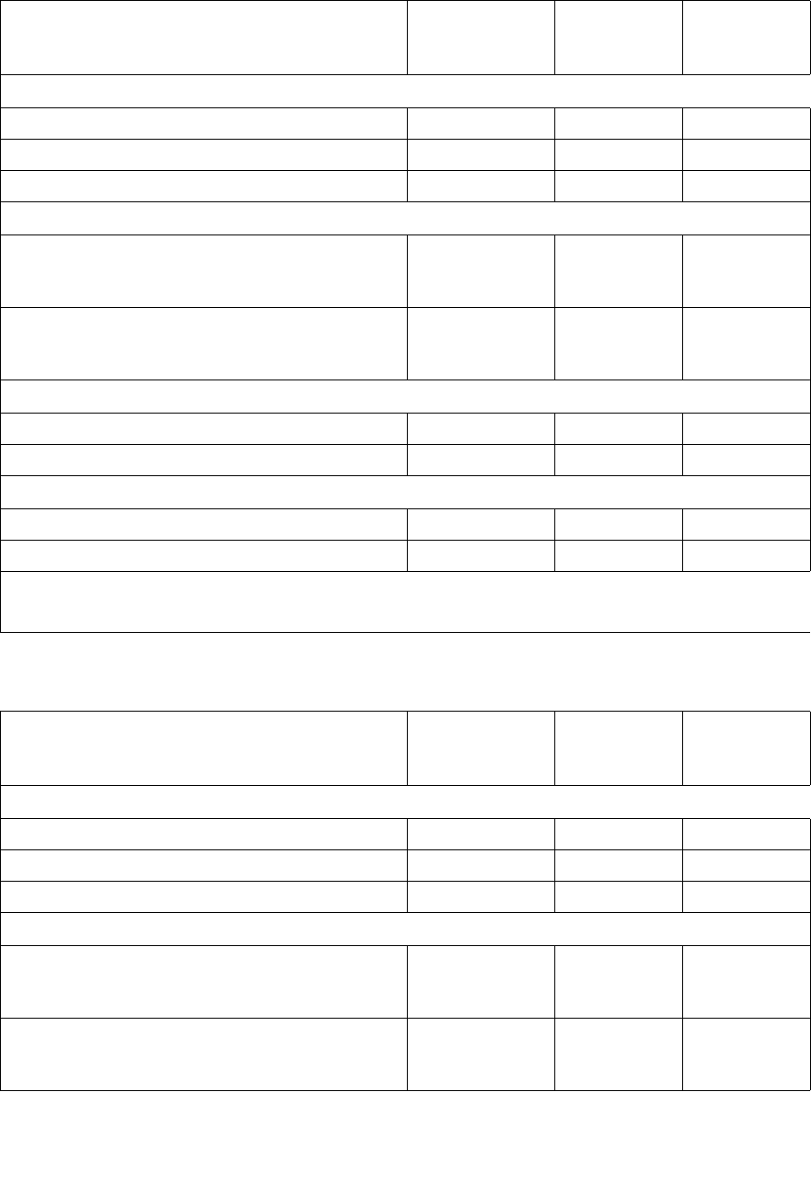
Capacity on Demand Features and Restrictions
96116 • Revision: KA Chapter 5 Capacity on Demand 139
LTO Licensed Capacity by Module
Mixed Media Licensed Capacity by Module
Module License Value
Module
Licensed
Capacity *
Library
Total Count
Base Module
Shipped standard LimitedBase 30
As last module FullBase 50
With any module underneath FullBase 66
Drive Expansion Module (DEM)
As last module ThirdDEM
(increments of
26, 26, 25)
77
With any module underneath ThirdDEM
(increments of
28, 28, 28)
84
Cartridge Expansion Module (CEM) after Base Module or DEM
As last module FullCEM 104
With any module underneath FullCEM 114
Cartridge Expansion Module (CEM) after CEM
As last module FullCEM 110
With any module underneath FullCEM 120
* All capacities assume no reserved cells and all CAPs are configured for enter and eject op-
erations.
Module License Value
Module
Licensed
Capacity *
Library
Total Count
Base Module
Shipped standard LimitedBase 24
As last module FullBase 42
With any module underneath FullBase 56
Drive Expansion Module (DEM)
As last module ThirdDEM
(increments of
21, 21, 21)
63
With any module underneath ThirdDEM
(increments of
24, 23, 23)
70

Capacity on Demand Features and Restrictions
140 SL500 User’s Guide • July 2008 Revision: KA • 96116
Cell Assignment Rules
The library controller uses the following rules when filling licensed storage cells with
cartridges:
■All cells in column 1 are filled first, then the cells in column 2, then 3, and so on.
■Cells within each column are filled from top to bottom, starting with the first row
after any reserved cells. For example, if the top three cells in a column are reserved,
cell assignment within the column starts with row 4.
■Once all cells within a module are filled, cell assignment moves to the next module,
using the same top-to-bottom, column by column approach.
In partitioned libraries, the library controller applies these rules separately to each
partition.
Orphaned Cartridges in Non-Partitioned Libraries
Note – For a discussion of orphaned cartridges in partitioned libraries, see “Orphaned
Cartridges in Partitioned Libraries” on page 152.
In non-partitioned libraries, an orphaned cartridge is a cartridge located in an
unlicensed storage cell. Orphaned cartridges are inaccessible to all hosts.
A cartridge can become orphaned for a variety of reasons. Following are some possible
causes:
■Licensed storage capacity has been reduced.
■The cartridge has been moved to an unlicensed or inaccessible cell through manual
intervention.
Cartridge Expansion Module (CEM) after Base Module or DEM
As last module FullCEM 84
With any module underneath FullCEM 94
Cartridge Expansion Module (CEM) after CEM
As last module FullCEM 90
With any module underneath FullCEM 100
* All capacities assume no reserved cells and all CAPs are configured for enter and eject op-
erations.
Module License Value
Module
Licensed
Capacity *
Library
Total Count

Implementing Changes to Licensed Capacity
96116 • Revision: KA Chapter 5 Capacity on Demand 141
Implementing Changes to Licensed
Capacity
Increasing Licensed Capacity
Following are special considerations for installing new licensed storage capacity.
■See “License Installation Process” on page 120 for details on purchasing and
installing a Capacity license.
■If the new licensed capacity exceeds the physical capacity, no corrective action is
necessary. Physical cells that cannot be activated due to licensed capacity limits will
be activated later whenever additional licensed capacity is installed.
■You must configure all affected library host applications to recognize the new
licensed storage cells. See “Host Notification of Capacity Changes” on page 142 for
details.
■In non-partitioned libraries, all newly licensed cells are immediately available for
use.
■In partitioned libraries, all newly licensed cells are added as “unallocated,” and are
therefore not available for use. You must manually allocate the new cells to
partitions before the cells can be used for cartridge storage. See “Partition
Configuration Tasks” on page 156 for detailed instructions.
Decreasing Licensed Capacity
Following are special considerations for deleting licensed storage capacity.
Caution – Deleting licensed capacity is an exceptional situation; use caution when
doing so.
■See “Delete a License Key File” on page 126 for details on deleting licensed capacity.
■Storage cells corresponding to the reduced capacity will become inaccessible, and
any cartridges within those cells will be orphaned. No checks are made to identify
cartridges that will be orphaned. See “Orphaned Cartridges in Non-Partitioned
Libraries” on page 140 for details.
■You must configure all affected library host applications to recognize the licensed
storage cell changes. See “Host Notification of Capacity Changes” on page 142 for
details.
■For partitioned libraries:
■The total number of storage cells allocated to all library partitions cannot exceed
the licensed capacity of the library.
Caution – You must manually de-allocate cells from partitions so the total allocation
does not exceed the new licensed capacity.

Implementing Changes to Licensed Capacity
142 SL500 User’s Guide • July 2008 Revision: KA • 96116
■If, after capacity has been decreased, the total number of cells allocated to all
partitions is still less than the new licensed capacity, you do not need to
reconfigure the partitions.
Host Notification of Capacity Changes
When storage capacity is added or removed, the library controller notifies all affected
hosts according to their interface requirements. SCSI hosts are notified by a “Mode
Parameters Changed” unit attention. The host must re-audit the library to determine
the specific configuration changes. See the appropriate tape management software
documentation for detailed procedures and commands.

Partitioning Features and Restrictions
96116 • Revision: KA Chapter 6 Library Partitioning 143
6
Library Partitioning
Note – Starting with SL500 firmware version 1300 and SL Console version FRS_4.00,
library partitioning upgrades must be installed through the SL500 licensing utility.
Partitioning established on a library prior to version 1300 is retained permanently. See
Chapter 4, “Licensing” for details.
Library partitioning allows sections of the SL500 library to be assigned for exclusive use
by specified hosts. For example, you can configure one group of storage cells and
drives to be used only for Veritas operations, and another group only for Tivoli
operations. This allows you to configure an SL500 library for applications running on
multiple hosts and operating systems.
Partitioning Features and Restrictions
This section describes important features and restrictions of library partitioning that
will help you to configure and use partitioning in your SL500 library.
■You can configure up to eight partitions within an SL500 library.
■A partition can be as small as a single storage cell, CAP cell, or tape drive. Cells and
drives within a partition do not need to be adjacent.
■Storage cells and tape drives allocated to a partition can be used only by the hosts
assigned to that partition. Hosts assigned to other partitions cannot access the
contents of these cells and drives. See “Storage Cells and Drives” on page 150 for
details.
■Storage cells and drives not allocated to any partition cannot be accessed by any
hosts. For example, you might leave an area of cells unallocated, in preparation for
future partitioning.
■CAP cells can be allocated for exclusive use by a partition, or they can be left
unallocated for common use by all hosts. See “Partitions and CAPs” on page 151 for
details.

System Requirements for Library Partitioning
144 SL500 User’s Guide • July 2008 Revision: KA • 96116
System Requirements for Library
Partitioning
Note – Starting with SL500 firmware version 1300 and SL Console version FRS_4.00,
library partitioning upgrades must be installed through the SL500 licensing utility.
Partitioning established on a library prior to version 1300 is retained permanently. See
Chapter 4, “Licensing” for details.
Note – ACSLS does not support partitioning on the SL500 library.
Enabling and Disabling Partitioning
In order for you to use partitions in a library, the partitioning feature must be enabled
by your StorageTek CSE. Contact your StorageTek CSE for assistance.
A library with partitioning enabled can be in either of the following states:
■Partitioned—The library has at least one user-defined partition with a valid partition
ID.
■Non-partitioned—The library has no user-defined partitions. A non-partitioned
library behaves in the same manner as a library that does not have partitioning
enabled; that is all storage cells, drives, and CAPs are accessible to all hosts.
To disable partitioning on a library, you must first delete all partitions. The library state
will then change to “non-partitioned.”
Partition Planning
The partitioning feature offers great flexibility in the use of your library. It also requires
careful planning, a thorough knowledge of library wall and storage cell mapping, and
expertise in configuring and administering host software applications. There must be
clear communication among all parties involved, including system programmers and
administrators, library operators, and your Sun service representative.
Before creating partitions, you must plan the storage area that is needed for resident
tape cartridges and anticipate the number of required free cells. You must understand
the boundaries of each partition and the host ownership relationships. You must verify
that all tape drives and cartridges have been moved to the proper locations, according
to the planned host/storage cell and host/tape drive assignments.

Partition Planning
96116 • Revision: KA Chapter 6 Library Partitioning 145
Installing the Partitioning Feature
The following special considerations apply after you successfully install the
Partitioning feature on a previously non-partitioned library.
■You must reboot the library after installing the Partitioning license.
■Until you create at least one partition, the library remains in a non-partitioned state;
that is all licensed storage cells, drives, and CAPs are accessible to all hosts.
Allocated Storage Capacity
In partitioned libraries, the total number of storage cells allocated to all library
partitions cannot exceed the licensed capacity of the library.
In partitioned libraries, there is no default active storage region. You must explicitly
assign storage cells to partitions, thereby configuring the active storage regions for each
partition. See “Partitioning Process” on page 153 for details.
Partition Configurations
You must use the standalone SL Console or Web-launched SL Console to configure
library partitions; the partitioning screens are not available on the local operator panel.
To configure a partition, you must define the following information:
■Partition Summary Information
■Host-Partition Connections
■Partition Boundaries
For detailed instructions on defining library partitions, see “Partitioning Process” on
page 153.
Partition Summary Information
Partition summary information includes the partition ID and name, and the barcode
format to be used on cartridge labels. Partition IDs must be unique and can range from
1–8.
Host-Partition Connections
Host-partition connections identify the hosts that are able to access a partition. Each
partition appears to the host as a separate library module. A host can control one or
more partitions. In addition, it is possible for more than one host to control a single
SCSI partition, but it is recommended that you exercise caution in implementing this
configuration, as some host applications may not allow for resource sharing.
A partition can have one or more host-partition connections. The host-partition
connection configuration is user-defined and consists of the following information:
■World Wide Port Name of the host bus adapter
■Port number of the library Fibre Channel card

Partition Planning
146 SL500 User’s Guide • July 2008 Revision: KA • 96116
■Logical unit number (LUN) of the partition on the host
See “Configure a Host-Partition Connection” on page 160 for detailed instructions on
defining this information.
Partition Boundaries
Partition boundaries identify the storage cells, drives, and CAP cells that are part of
each partition. Only unallocated cells can be added to a partition, and only allocated
cells can be removed.
You can define partition boundaries in any of the following ways:
■Select individual cells or rectangular groups of cells to add or remove from a
partition. Cells or cell groups do not have to be contiguous.
■Select an entire module side to add or remove from a partition. Sides do not have to
be contiguous.
■Select an entire module to add or remove from a partition. Modules do not have to
be contiguous.
Sample Partition Configuration
FIGURE 6-1 on page 147 shows a sample SL500 library partition configuration. In this
example, there are three defined partitions:
■Partition 1
■Partition 2
■Partition 6
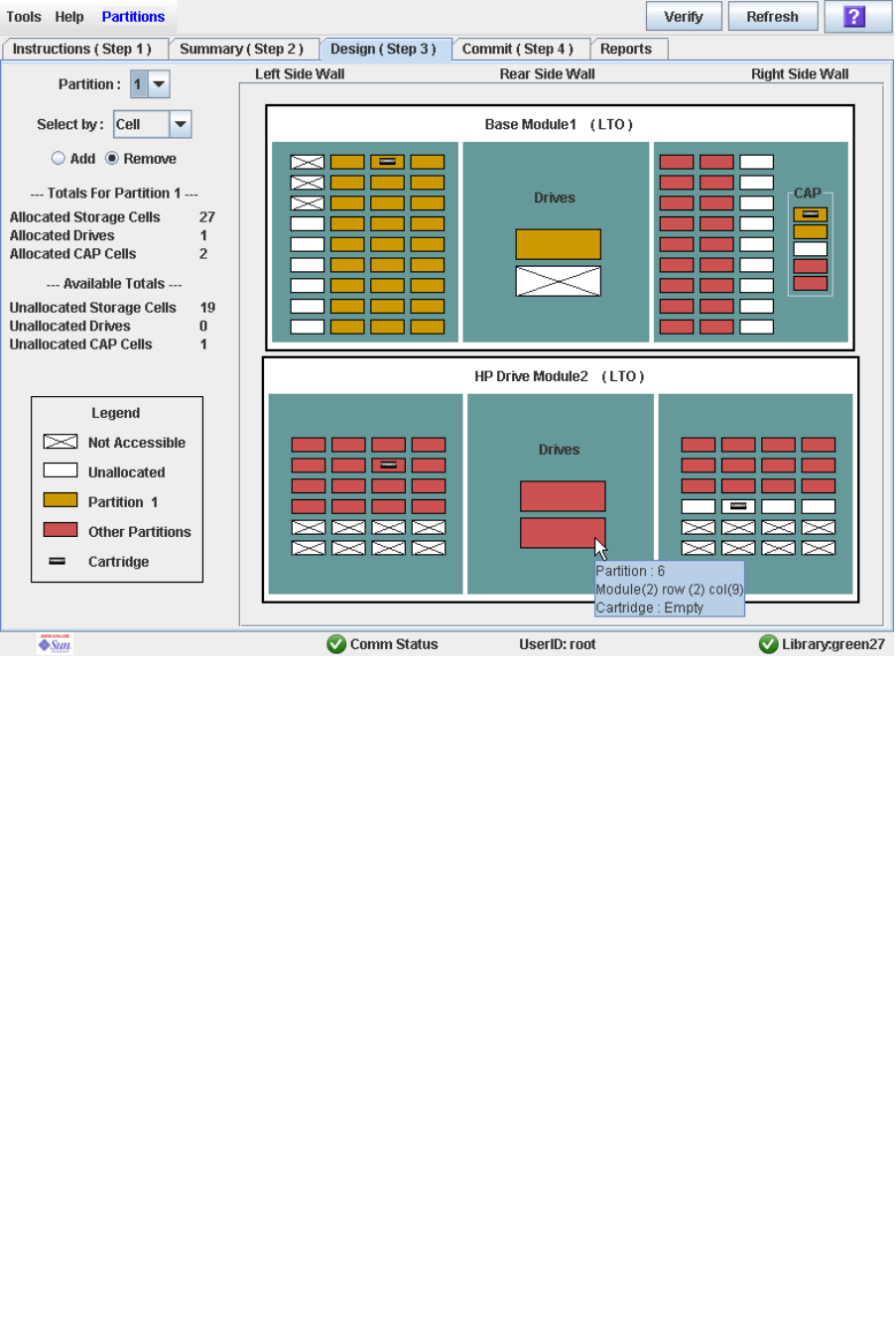
Partition Planning
96116 • Revision: KA Chapter 6 Library Partitioning 147
FIGURE 6-1 Library Partition Example

Deleting the Partitioning Feature
148 SL500 User’s Guide • July 2008 Revision: KA • 96116
The screen display is from the perspective of Partition 1, therefore the resources
allocated to Partition 1 are shown in gold, and the resources allocated to Partition 2 and
Partition 6 are shown in red. TABLE 6-1 on page 148 describes the resource allocation in
detail.
Deleting the Partitioning Feature
You can delete the Partitioning feature by deleting the Partitioning license key file from
the library. See “Delete a License Key File” on page 126 for detailed instructions. You
must reboot the library after deleting the Partitioning license in order for the deletion to
take effect.
Note – Deleting the Partitioning feature is an exceptional situation; be sure this is what
you really want to do.
Deleting the Partitioning feature has the following effects on the library configuration:
■Changes the library state to “non-partitioned.”
■Makes all licensed storage cells, drives, and CAPs accessible to all hosts.
■All existing partition summary information and resource allocations are retained,
but not usable. If the Partitioning license is later re-installed, the partition allocations
are restored.
TABLE 6-1 Partition Example—Resource Description
Resource Group Included Resources
Partition 1 All resources are shown in gold. Includes the following:
■Tape drive in the Base Module
■Storage cells in the left side of the Base Module
■Top two CAP cells in the Base Module
Partition 2 All resources are shown in red. Includes the following:
■Top tape drive in the Drive Module
■Storage cells in the right side of the Base Module
■No allocated CAP cells
Partition 6 All resources are shown in red. Includes the following:
■Bottom tape drive in the Drive Module
■Storage cells in the Drive Module
■Bottom two CAP cells in the Base Module
Common CAP cell Middle CAP cell in the Base Module
Unassigned All resources shown in white
Not Accessible All resources shown x’ed out
Orphaned
cartridge
Cartridge in unallocated (white) storage cell in the Base Module

Partitions and Library Resources
96116 • Revision: KA Chapter 6 Library Partitioning 149
Partitions and Library Resources
Library Resource Addresses
Resource addresses uniquely identify each resource (storage cells, drives, and CAP
cells) within the library. The SL500 library and attached hosts use the following
addressing schemes:
■Library Internal Address
■Host SCSI Element Address
Each partition appears to a host as a separate library; this is reflected in the partition
address.
Library Internal Address
The library internal address is used by the SL500 library controller and the SL Console
device tree to identify the physical location of each resource. The addressing scheme
used by the SL500 is a four-digit, comma-separated value, specifying the library,
module, row, and column, as viewed from inside the library, facing the drive bays. This
addressing scheme is commonly referred to as the LMRC address.
The format of the SL500 LMRC address is l,m,r,c where:
■l= library or partition number. In partitioned libraries, l is the partition ID (1–8). In
non-partitioned libraries, l is always “0”.
■m = module number (1–5). The Base Module is 1, additional drive expansion and
storage expansion modules are 2–5.
■r = row number. Numbered consecutively from the top, down, with row 1 at the top.
■c = column number, as follows:
■Base module, left side of library = 1–4
■Base module, right side of library = 5–8
■DEM (Drive Expansion Module) drive column, rear of library = 9
■CEM (Cartridge Expansion Module) columns, rear of library = 9–11
Internal Address Examples
■If the entire Base Module is allocated to Partition 1, the internal address for a
cartridge in row 8, column 1 in the Base Module is: 1, 1, 8, 1.
■If the entire CEM is allocated to Partition 2, the internal address for a cartridge in
row 10, column 1 is: 2, 2, 10, 1.
Host SCSI Element Address
The element address is used by hosts to uniquely identify each library resource
available to the host.
Partitions and Library Resources
150 SL500 User’s Guide • July 2008 Revision: KA • 96116
SCSI element numbering uses a single integer to identify each library resource. SCSI
element numbering within partitioned libraries is continuous for each partition, even if
cell locations for the partition are not adjacent. SCSI element addresses for a partition
start at the lowest module, row, and column within the partition, then proceed by row
until the end of the column, then increment by column until the end of the module.
When additional resources are allocated to an existing SCSI partition, the original
resources are not renumbered. This helps to minimize disruption to the SCSI host.
SCSI Element Address Examples
If a library’s base and storage expansion modules are allocated to Partition 1 and the
drive module is allocated to Partition 2, SCSI element numbering is as follows:
■Numbering for Partition 1 begins at the first available storage cell in the Base
Module and continues through the last available cell in the storage module cell.
■Numbering for Partition 2 begins with the first available storage cell in the drive
module PRC Address and ends with the last available cell in that module.
Storage Cells and Drives
All storage cells, tape drives, and cartridges allocated to a partition are owned
exclusively by the assigned host and cannot be accessed by other hosts. For example, if
a group of tape drives is allocated to a partition, only the host assigned to that partition
can use those drives.
Storage cells and drives that are not allocated to any partition cannot be accessed at all.
For example, you can leave an area of cells unallocated in preparation for a planned
future partition.
On the SL Console screens and reports, storage cells and drives appear in any of the
following states:
■Allocated—Assigned to the current partition.
■Unallocated (or Unassigned)—Not assigned to any partition; available to be assigned
to any current partition.
■Unavailable—Assigned to another partition.
■Not accessible—Not available for host operations; for example, cells reserved for
diagnostic cartridges, cells that are physically blocked.
Note – HandBots are shared resources and cannot be allocated exclusively to a
partition.
To display partition assignments for storage cells and drives, see
“Partitions—Reports—Cartridge Cell and Media Summary” on page 229.

Partitions and CAPs
96116 • Revision: KA Chapter 6 Library Partitioning 151
Partitions and CAPs
The cells within each CAP can be allocated or unallocated individually to partitions.
This allows for the following possible CAP configurations:
■Common CAP
■Split CAP
Note – Split CAPs are available to the SL500 only.
Common CAP
In a common, or unassigned, CAP, all cells in the CAP are left unallocated and can be
used by any partition that does not have any CAP cells allocated to it. CAP cells are
common by default—any CAP cells that are not explicitly allocated to a partition are
treated as common.
A common CAP is a shared library resource. Each host must select a common CAP to
use it and must release the CAP when done, to make it available to other hosts. No
other host can access the CAP until the first host has completed the operation and
released the CAP. For additional details, see “CAP Operations” on page 151.
Split CAP
In a split CAP, the cells in the CAP are allocated to one or more partitions. Each
individual CAP cell can be allocated to one partition only. Cells in a split CAP can be
allocated in any of the following ways:
■All cells can be allocated to one partition.
■All cells can be distributed among multiple partitions. For example, in an eight-cell
CAP, two cells could be allocated to Partition 1, one cell to Partition 2, and the
remaining cells to Partition 3.
■Some cells can be allocated to one partition and the remainder left unallocated, or
common. For example, in an eight-cell CAP, five cells could be allocated to
Partition 3, and the remaining cells left common.
When configuring a split CAP, you must plan carefully for anticipated CAP usage. A
partition with allocated CAP cells can use the cells allocated to it only. It cannot use
CAP cells allocated to other partitions, nor can it use common CAP cells.
CAP Operations
In a partitioned library, it is recommended that you assign partitions to the CAP Open
button on the library control panel prior to pressing the button to open the CAPs.

Partitions and CAPs
152 SL500 User’s Guide • July 2008 Revision: KA • 96116
Once you have assigned partitions to the CAP Open button, only CAPs containing cells
that are accessible to those partitions will open. Depending on how your library’s CAPs
are configured, this operation may expose CAP cells that are not accessible to the
selected partitions. As a safeguard, however, CAPs that contain only inaccessible cells
and CAPs with cartridges in inaccessible cells do not open.
For detailed instructions, see “Enter Cartridges Into a Partitioned Library” on page 187
and “Eject Cartridges From a Partitioned Library” on page 190.
Orphaned Cartridges in Partitioned Libraries
Note – For a discussion of orphaned cartridges in non-partitioned libraries, see
“Orphaned Cartridges in Non-Partitioned Libraries” on page 150.
In partitioned libraries, an orphaned cartridge is a cartridge located in an unallocated
cell or drive (that is, a cell or drive not allocated to any defined partition).
Caution – If a host encounters an orphaned cartridge it might treat the cartridge as
scratch and overwrite the data. Therefore, it is very important to disposition orphaned
cartridges properly.
A cartridge can become orphaned for a variety of reasons. Following are some possible
causes:
■Partition boundaries have changed.
■A partition has been deleted.
■The cartridge has been moved to an unallocated or inaccessible cell through manual
intervention.
If the SL Console identifies an orphaned cartridge, it displays a warning message. You
can then use the following tools to help you resolve and disposition the orphaned
cartridge:
■Generate a report of orphaned cartridges.
■Perform an audit of the library.
■Perform a recovery move on a cartridge.
For detailed instructions on checking for and resolving orphaned cartridges, see the
following procedures:
■“Verify Partition Configurations” on page 164
■“Resolve Orphaned Cartridges” on page 166
■“Commit Partition Configuration Changes” on page 167

Partitioning Process
96116 • Revision: KA Chapter 6 Library Partitioning 153
Partitioning Process
Note – Starting with SL500 firmware version 1300 and SL Console version FRS_4.00,
library partitioning upgrades must be installed through the SL500 licensing utility.
Partitioning established on a library prior to version 1300 is retained permanently. See
Chapter 4, “Licensing” for details.
Partition Configuration Process
When configuring library partitions for the first time, it is recommended that you use
the library partition screens in the following sequence:
1. Instructions (Step 1)—Review summary instructions for the partition configuration
process.
2. Summary (Step 2)—Display summary partition configuration and host-partition
connection information. Optionally access other screens to perform the following
tasks:
■Add Partition
■Modify Partition
■Delete Partition
■Add Connection
■Modify Connection
■Delete Connection
3. Design (Step 3)—Display and optionally modify detailed partition boundary
information. Optionally access other screens to perform the following tasks:
■Verify Partition Configurations
■Refresh the display with current data from the library controller database
4. Commit (Step 4)—Commit all changes made in the Summary(2) and Design (3)
screens, and all associated popups, to the library controller database. Optionally
access other screens to perform the following task:
■Refresh the display with current data from the library controller database
You can use the Reports screen at any time to display, and optionally save or print,
partition configuration information from the library controller database.
SL Console Partition Workspace
The partition Summary (Step 2) and Design (Step 3) screens, and all associated
popups, give you a dynamic workspace to design your library partitions. All partition
configuration information is automatically saved to the partition workspace in
SL Console memory and retained for the duration of your SL Console session. This
allows you to switch among partition views and leave and return to the partition
screens any number of times without losing your configuration changes.

Partitioning Process
154 SL500 User’s Guide • July 2008 Revision: KA • 96116
Information in the SL Console partition workspace is committed to the library
controller database only through the Commit (Step 4) screen. The information is lost if
any one of the following occurs before you have committed your updates:
■You actively log off the SL Console session.
■The SL Console session times out or the connection to the library is lost.
■You actively refresh the SL Console workspace from the current library controller
database. This is done through the Refresh button on the Summary (Step 2) and
Design (Step 3) screens.
Caution – For the following reasons, it is recommended that you make the library
unavailable to other users before committing your partition workspace changes.
There is no real-time validation of partition boundaries against the library controller
database; therefore if you do not make the library unavailable and other users are
performing cartridge movements or library configuration changes, configuration
conflicts may arise. See “Synchronizing the Display With the Controller Database” on
page 31 for details.
The library temporarily drops all connections to HSC or ACSLS hosts when partition
configurations changes are committed. The hosts will automatically reconnect, but
multiple error messages will be displayed, and cartridge management tasks in progress
may fail.

Partitioning Task Summary
96116 • Revision: KA Chapter 6 Library Partitioning 155
Partitioning Task Summary
Partitioning tasks are divided into the following categories:
■“Partition Configuration Tasks” on page 156
■“Partition Management Tasks” on page 170
■“Partition Report Tasks” on page 181
■“CAP Operation Tasks” on page 186

Partition Configuration Tasks
156 SL500 User’s Guide • July 2008 Revision: KA • 96116
Partition Configuration Tasks
Task Page
Review Partitioning Instructions 157
Create a Partition 158
Configure a Host-Partition Connection 160
Design a Partition 162
Verify Partition Configurations 164
Resolve Orphaned Cartridges 166
Commit Partition Configuration Changes 167
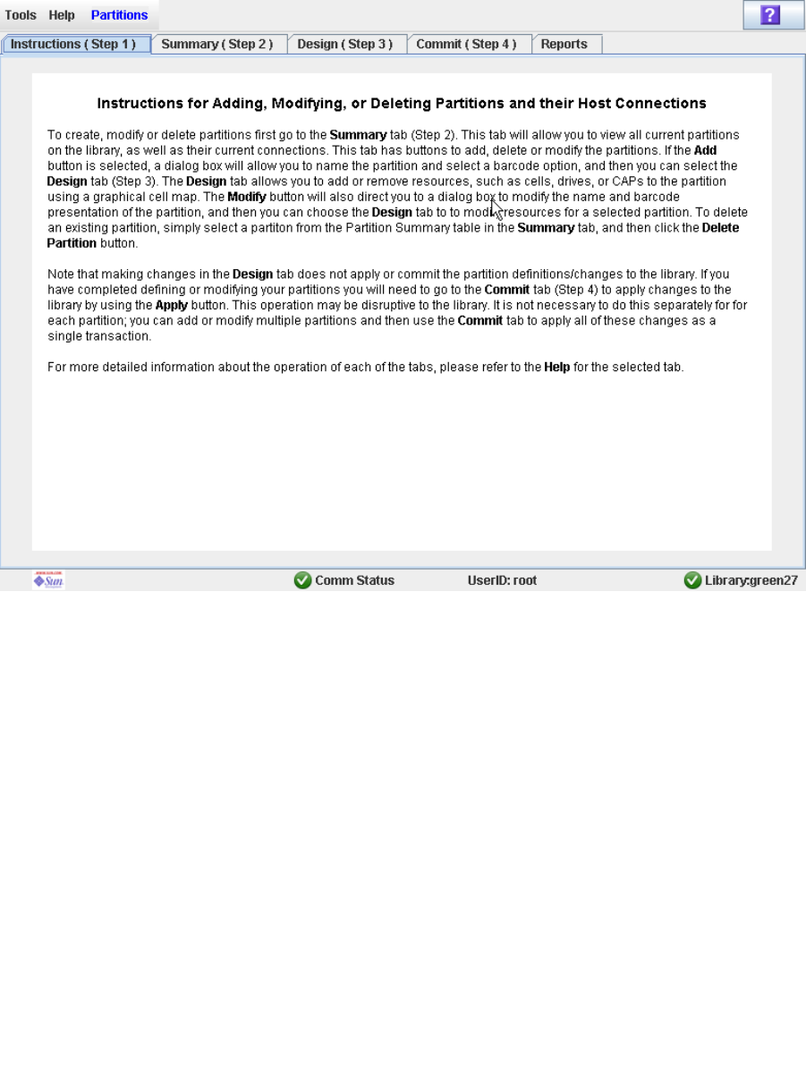
Partition Configuration Tasks
96116 • Revision: KA Chapter 6 Library Partitioning 157
▼ Review Partitioning Instructions
Use this procedure to review the partitioning process.
1. Select Tools > Partitions.
The first time you make this selection during an SL Console login session, the
Instructions (Step 1) screen appears automatically.
2. Review the instructions on the screen before proceeding with other partitioning
tasks.
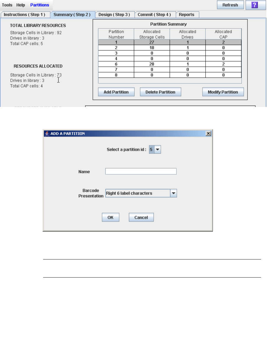
Partition Configuration Tasks
158 SL500 User’s Guide • July 2008 Revision: KA • 96116
▼ Create a Partition
Use this procedure to create a new library partition and assign its storage capacity. You
can create up to eight partitions, with IDs from 1–8.
1. Select Tools > Partitions, and click the Summary (Step 2) tab.
The Summary (Step 2) screen appears.
2. Click Add Partition.
The Add Partition popup appears.
3. Select the Partition ID you want to add, and enter the Name, and Barcode
Presentation.
Note – Partition IDs do not need to be contiguous. For example, you can create
partition 2 and partition 4, with no partitions 1 or 3.

Partition Configuration Tasks
96116 • Revision: KA Chapter 6 Library Partitioning 159
4. Click OK.
Your partition configuration changes are saved to the SL Console partition workspace
for the duration of this login session.
To update the library controller database with all changes from this SL Console login
session, see “Verify Partition Configurations” on page 164 and “Commit Partition
Configuration Changes” on page 167.
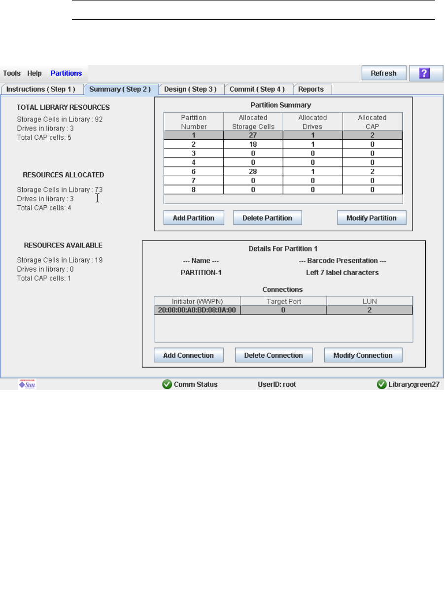
Partition Configuration Tasks
160 SL500 User’s Guide • July 2008 Revision: KA • 96116
▼ Configure a Host-Partition Connection
Use this procedure to configure the connection between a host and a selected partition.
You must perform this procedure in order for the partition to be accessible by the host.
Each partition can have up to nine host connections, each with a unique LUN. Also,
each host can connect to multiple partitions.
Note – The SL500 supports only SCSI connections between the host and library.
1. Select Tools > Partitions, and click the Summary (Step 2) tab.
The Summary (Step 2) screen appears.
2. Click the partition to which you want to add a host connection
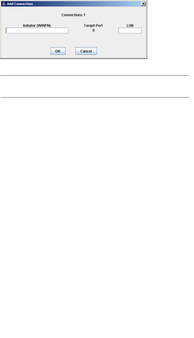
Partition Configuration Tasks
96116 • Revision: KA Chapter 6 Library Partitioning 161
3. Click Add Connection.
The Add Connection popup appears.
4. Enter the Initiator (WWPN) and LUN.
Note – Each initiator connected to the library must have one library partition assigned
to LUN 0. When you verify or commit partition configuration changes, the SL Console
will notify you if an initiator does not meet this requirement.
5. Click OK.
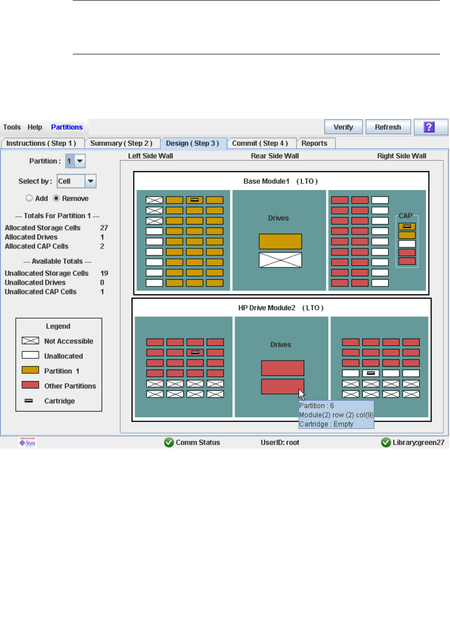
Partition Configuration Tasks
162 SL500 User’s Guide • July 2008 Revision: KA • 96116
▼ Design a Partition
Use this procedure to add or remove library resources (storage cells, tape drives, and
CAP cells) from a partition.
Note – Library resources can be allocated to only one partition at a time. If you want to
add resources to a partition but the resources are already allocated to another partition,
you must first remove the resources from the assigned partition, and then add them to
the new partition.
1. Select Tools > Partitions.
2. Click the Design (Step 3) tab.
The Design (Step 3) screen appears, displaying the current configuration of the library.
3. In the Partition pull-down menu, select the partition you want to configure.
All screen fields are updated to reflect the current configuration for the selected
partition.
4. Choose the Select by method, and click either the Add or Remove radio button.
5. Use the library map to select the resources you want to add or remove.

Partition Configuration Tasks
96116 • Revision: KA Chapter 6 Library Partitioning 163
Note – See “Partitions—Design (Step 3)” on page 212 for detailed instructions on using
the library map.
Your partition configuration changes are saved to the SL Console partition workspace
for the duration of this login session.
To update the library controller database with all changes from this SL Console login
session, see “Verify Partition Configurations” on page 164 and “Commit Partition
Configuration Changes” on page 167.
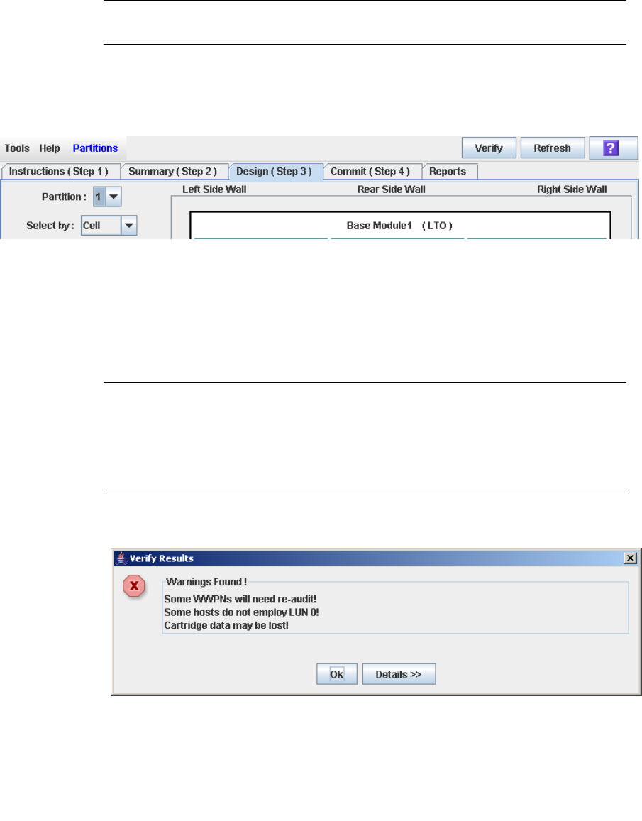
Partition Configuration Tasks
164 SL500 User’s Guide • July 2008 Revision: KA • 96116
▼ Verify Partition Configurations
Use this procedure to verify partition configuration changes you have made during this
SL Console login session. This procedure warns you of the following possible errors:
■A partition has orphaned cartridges. See “Orphaned Cartridges in Partitioned
Libraries” on page 152 for details.
■Library resources have been removed from a partition.
■A host connected to the library does not have a partition assigned to LUN 0.
Note – This procedure verifies only one partition at a time. If you need to verify
multiple partitions, you must repeat this procedure separately for each partition.
1. Select Tools > Partitions.
2. Click the Design (Step 3) tab.
The Design (Step 3) screen appears, displaying the current configuration of the library.
3. In the Partition pull-down menu, select the partition you want to verify.
All screen fields are updated to reflect the current configuration for the selected
partition.
4. In the Options Bar, click Verify.
The boundaries of the selected partition are verified, including the locations of all tape
cartridges.
Note – This verification is performed on the current partition configuration in the
SL Console partition workspace only. It does not verify current partition boundaries
against the library controller database; therefore it cannot identify configuration
conflicts that may arise due to other users performing cartridge movements or library
configuration changes—through the command line interface, other SL Console sessions,
or host applications—at the same time you have made partition changes.
The Verify Results popup appears, indicating whether there are any orphaned
cartridges or other errors in the current partition configuration.
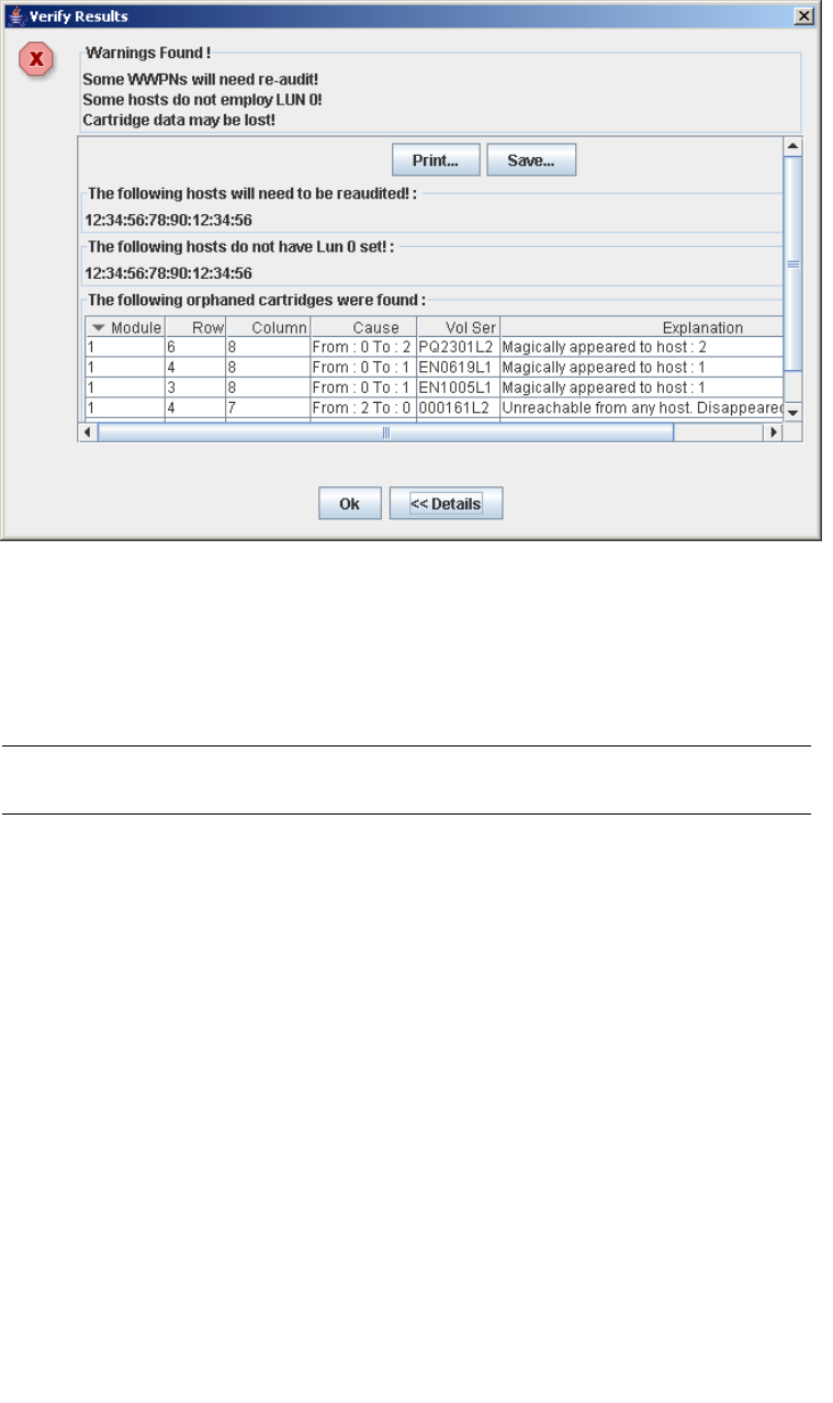
Partition Configuration Tasks
96116 • Revision: KA Chapter 6 Library Partitioning 165
5. To display detailed warning messages explaining the reasons for any orphaned
cartridges, click Details.
You can use the Details button to toggle between the expanded and collapsed views of
the warning messages.
6. Optionally, in the expanded view of the warning messages you can do the following:
■Click Print to print the detailed message data.
■Click Save to save the detailed message data to a comma-separated file.
7. Click OK to dismiss the Verify Results popup and return to the Design (Step 3)
screen.
Note – It is recommended that you follow the “Resolve Orphaned Cartridges” on
page 166 procedure before committing your changes to the library controller database.

Partition Configuration Tasks
166 SL500 User’s Guide • July 2008 Revision: KA • 96116
▼ Resolve Orphaned Cartridges
If the SL Console identifies an orphaned cartridge, it displays a warning message. You
should resolve and disposition all orphaned cartridges before proceeding to “Commit
Partition Configuration Changes” on page 167.
You can performing any of the following actions to resolve orphaned cartridges:
■Print a report of orphaned cartridges.
■Perform an audit of the library.
■Perform a recovery move on an orphaned cartridge.
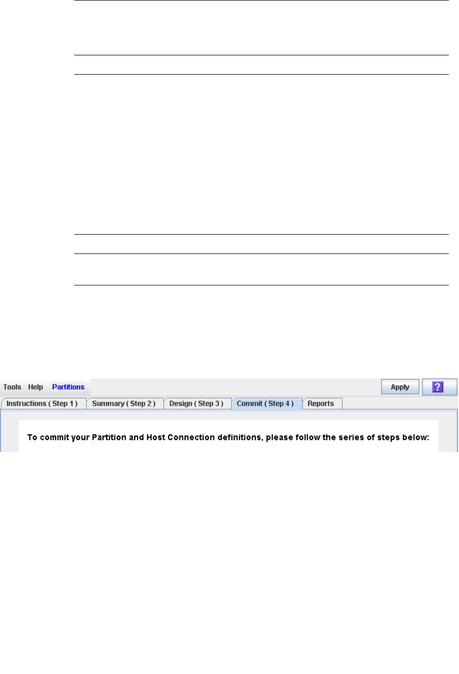
Partition Configuration Tasks
96116 • Revision: KA Chapter 6 Library Partitioning 167
▼ Commit Partition Configuration Changes
Caution – This procedure updates the library controller database with all partition
configuration changes you have made during this SL Console session. Failure to use
this procedure before logging out of the current SL Console session will cause all your
library configuration changes to be lost.
Caution – For the following reasons, it is recommended that you make the library
unavailable to other users before committing your partition workspace changes.
There is no real-time validation of partition boundaries against the library controller
database; therefore if you do not make the library unavailable and other users are
performing cartridge movements or library configuration changes, configuration
conflicts may arise. See “Synchronizing the Display With the Controller Database” on
page 31 for details.
The library temporarily drops all connections to HSC or ACSLS hosts when partition
configurations changes are committed. The hosts will automatically reconnect, but
multiple error messages will be displayed, and cartridge management tasks in progress
may fail.
Note – It is recommended that you follow the Resolve Orphaned Cartridges procedure
before performing this procedure.
1. Vary the library offline to ACSLS and HSC.
See the appropriate tape management software documentation for the procedures and
commands.
2. Select Tools > Partitions, and click the Commit (Step 4) tab.
The Commit (Step 4) screen appears.
3. In the Options Bar, click Apply.
The boundaries of the selected partition are verified, including the locations of all tape
cartridges.
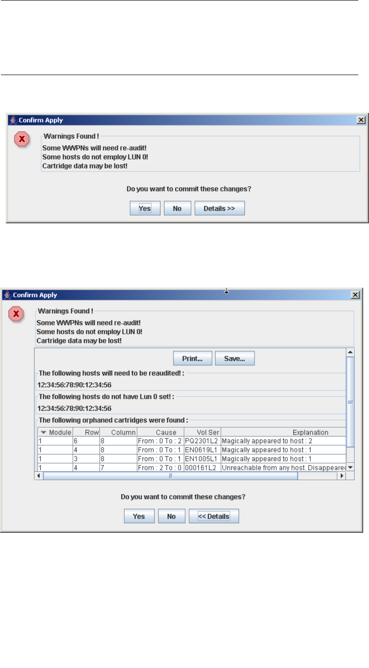
Partition Configuration Tasks
168 SL500 User’s Guide • July 2008 Revision: KA • 96116
Note – This verification is performed on the current partition configuration in the
SL Console partition workspace only. It does not verify current partition boundaries
against the library controller database; therefore it cannot identify configuration
conflicts that may arise due to other users performing cartridge movements or library
configuration changes—through the command line interface, other SL Console sessions,
or host applications—at the same time you have made partition changes.
The Confirm Apply popup appears, indicating whether there are any orphaned
cartridges or other problems in the current partition configuration.
4. To display detailed warning messages explaining the reasons for any orphaned
cartridges, click Details.
You can use the Details button to toggle between the expanded and collapsed views of
the warning messages.
5. Optionally, in the expanded view of the warning messages you can do the following:
■Click Print to print the detailed message data.
■Click Save to save the detailed message data to a comma-separated file.
6. Proceed as follows:
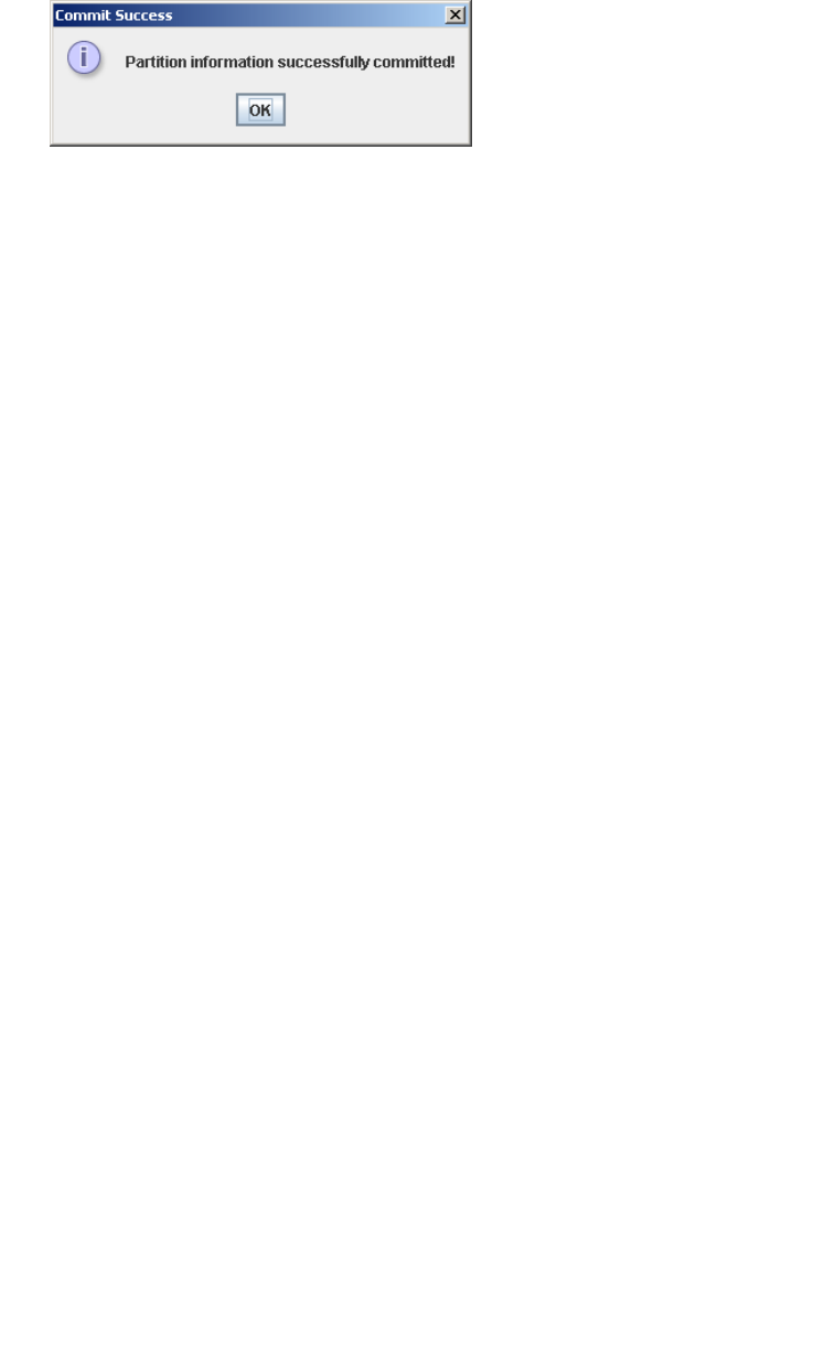
Partition Configuration Tasks
96116 • Revision: KA Chapter 6 Library Partitioning 169
■Click No to cancel the update. The library controller database is not updated, but all
partition changes from this login session are retained in the SL Console partition
workspace.
■Click Yes to update the library controller database.
The Commit Success popup appears.
Click OK to return to the Commit (Step 4) screen.
7. All affected library host applications must now be configured to recognize these
updates. See the appropriate tape management software documentation for the
procedures and commands.

Partition Management Tasks
170 SL500 User’s Guide • July 2008 Revision: KA • 96116
Partition Management Tasks
Task Page
Modify Partition Summary Information 171
Delete a Partition 172
Modify Host-Partition Connection Detail 174
Delete a Host-Partition Connection 176
Refresh the SL Console Partition Workspace 178
Reallocate Library Resources 179
Make a Hardware Change to a Partitioned Library 180
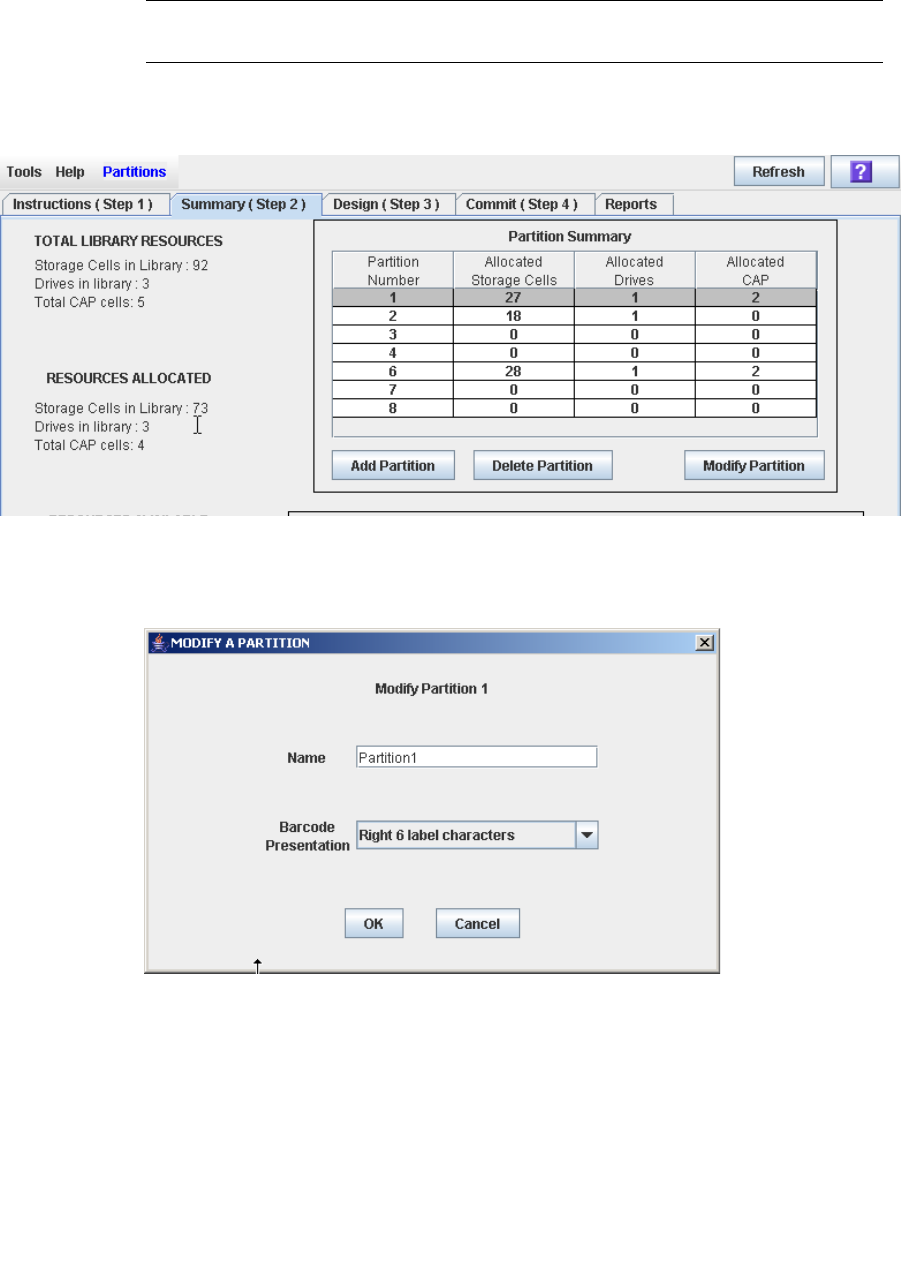
Partition Management Tasks
96116 • Revision: KA Chapter 6 Library Partitioning 171
▼ Modify Partition Summary Information
Use this procedure to change the name or barcode presentation format of an existing
partition.
Note – You cannot change the partition ID. To assign a different Partition ID, you must
delete the old partition and create a new one with the new ID.
1. Select Tools > Partitions, and click the Summary (Step 2) tab.
The Summary (Step 2) screen appears.
2. In the Partition Summary section, select the partition you want to modify.
3. Click Modify Partition.
The Modify a Partition popup appears.
4. Enter the changes you want to make.
5. Click OK to confirm the changes.
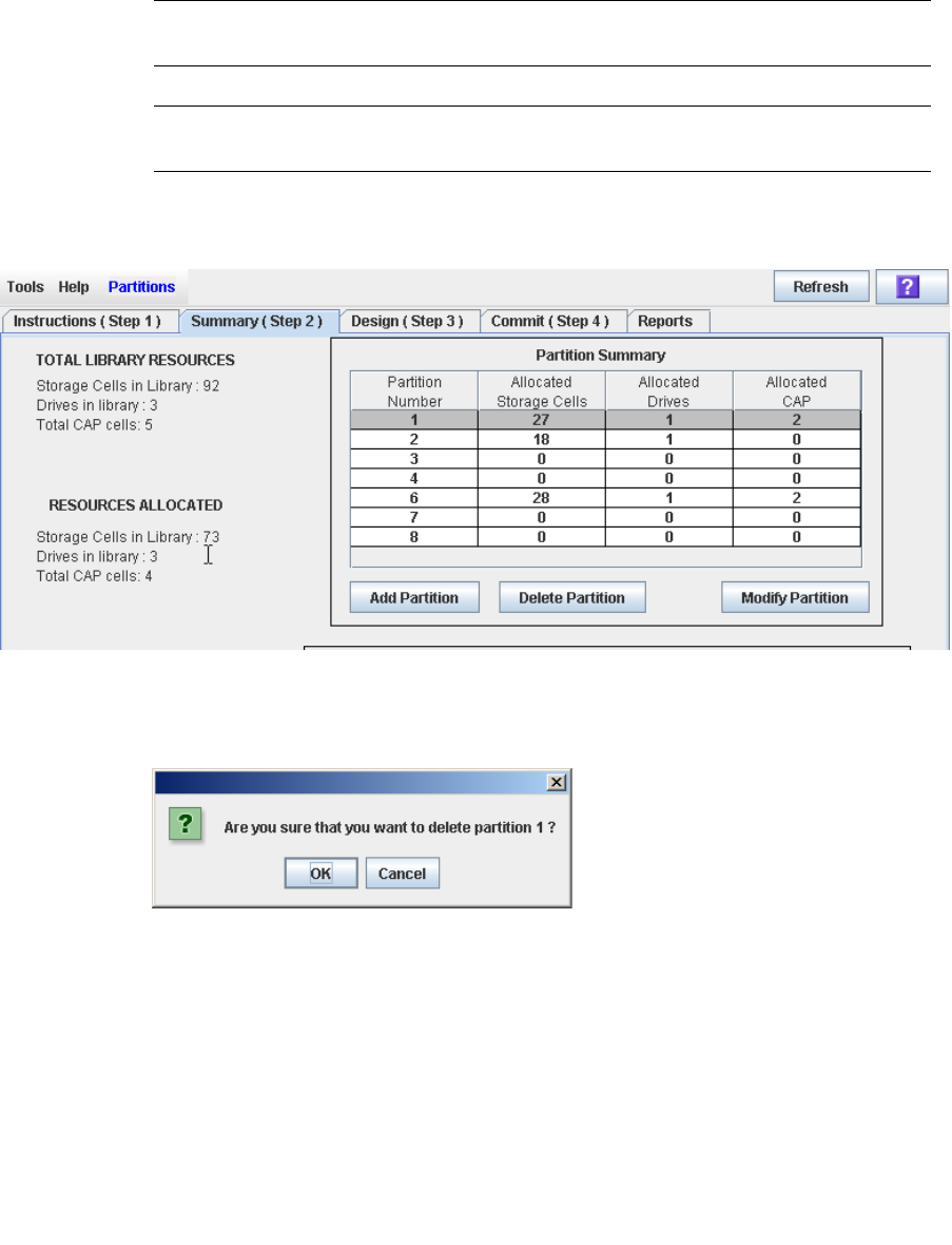
Partition Management Tasks
172 SL500 User’s Guide • July 2008 Revision: KA • 96116
▼ Delete a Partition
Use this procedure to delete a partition from the library. The following changes are
made to the library partition configuration:
■All resources allocated to the partition are marked available.
■All host connections for the partition are deleted.
■The partition ID is deleted.
Caution – Deleting partitions can result in orphaned cartridges and data that could be
lost. See “Orphaned Cartridges in Partitioned Libraries” on page 152 for details.
Note – Deleting all partitions from the library causes the library state to change to
“non-partitioned.” All storage cells, drives, and CAPs will be accessible to all hosts.
1. Select Tools > Partitions, and click the Summary (Step 2) tab.
The Summary (Step 2) screen appears.
2. In the Partition Summary section, click the partition you want to remove.
3. Click Delete Partition.
A confirmation popup appears.
4. Click OK to confirm the deletion.

Partition Management Tasks
96116 • Revision: KA Chapter 6 Library Partitioning 173
5. The updates are made as follows:
Your partition configuration changes are saved to the SL Console partition workspace
for the duration of this login session.
To update the library controller database with all changes from this SL Console login
session, see “Verify Partition Configurations” on page 164 and “Commit Partition
Configuration Changes” on page 167.
If there are no partitions remaining in the library, when you commit the updates the
library state will change to “non-partitioned”.
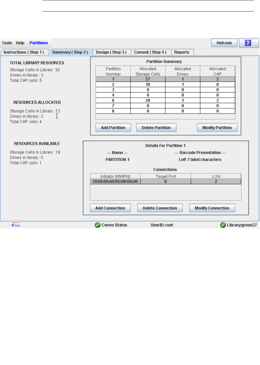
Partition Management Tasks
174 SL500 User’s Guide • July 2008 Revision: KA • 96116
▼ Modify Host-Partition Connection Detail
Use this procedure to modify the host World Wide Port Name or LUN number of the
library for a host-partition connection.
Note – You cannot modify the target port number for the library; it is always “0”.
1. Select Tools > Partitions, and click the Summary (Step 2) tab.
The Summary (Step 2) screen appears.
2. In the Summary section of the screen, click the partition for which you want to
modify a connection.
3. In the Connections section, click the host-partition connection you want to modify.
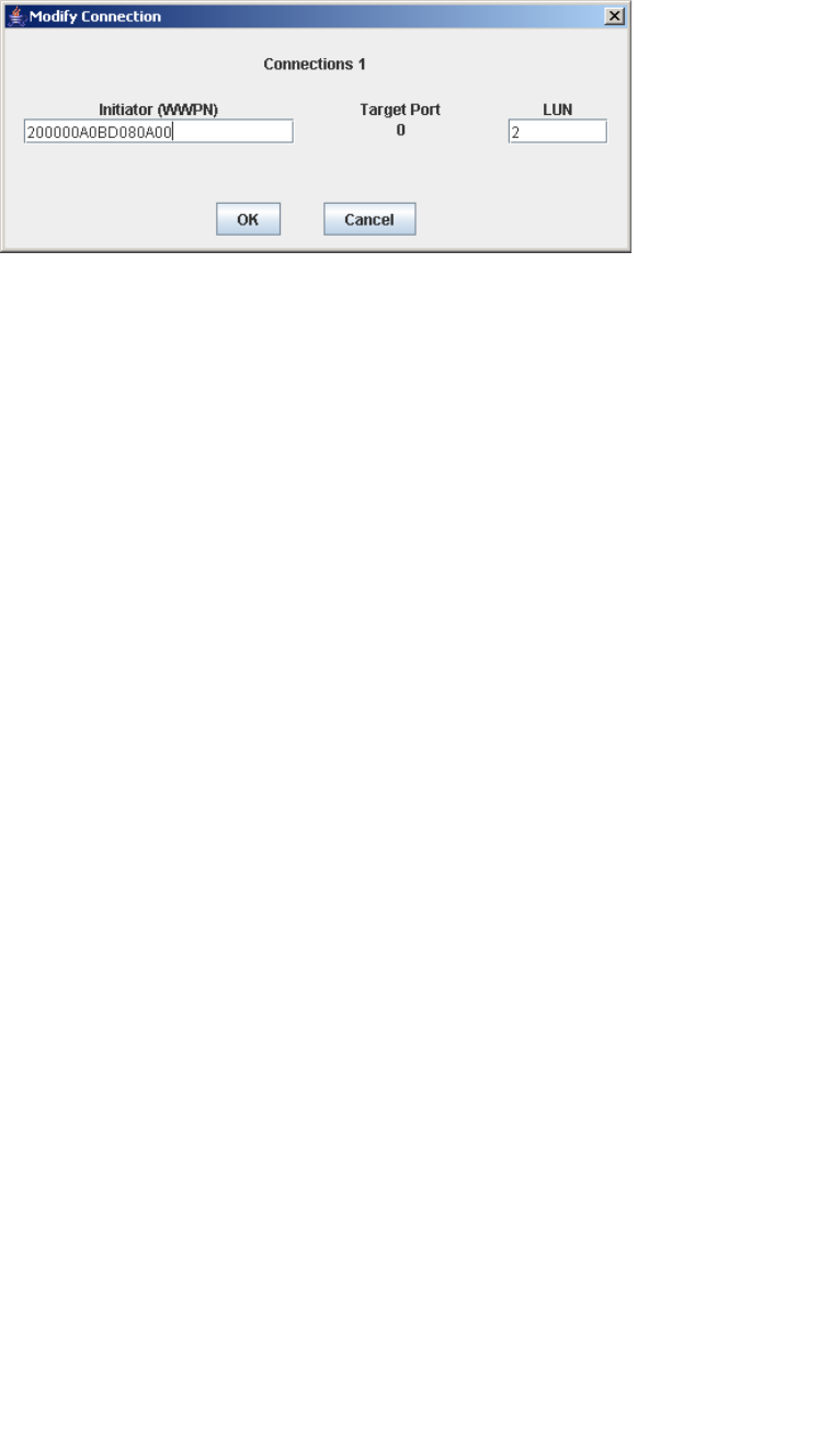
Partition Management Tasks
96116 • Revision: KA Chapter 6 Library Partitioning 175
4. Click Modify Connection.
The Modify a Connection popup appears.
5. Enter the changes you want to make.
6. Click OK to confirm the changes.
Your partition configuration changes are saved to the SL Console partition workspace
for the duration of this login session.
To update the library controller database with all changes from this SL Console login
session, see “Verify Partition Configurations” on page 164 and “Commit Partition
Configuration Changes” on page 167.
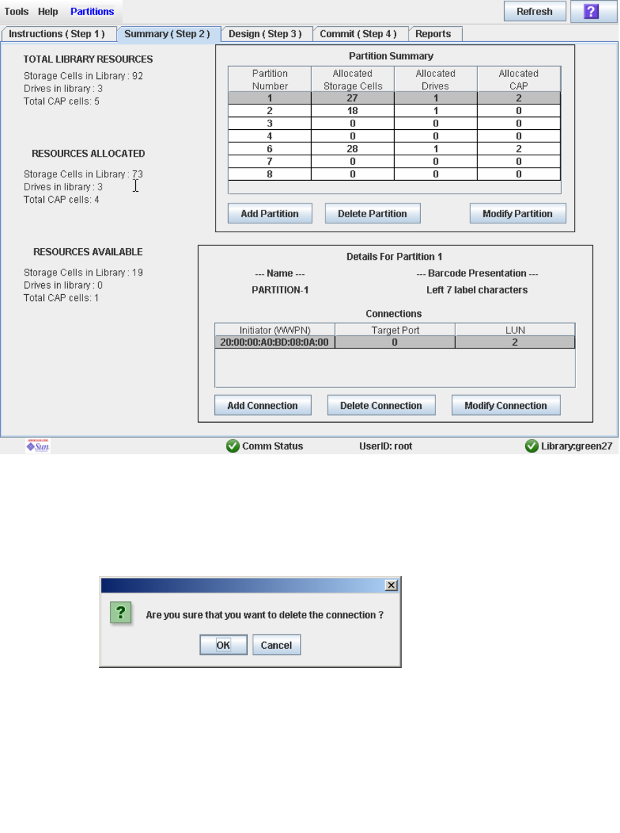
Partition Management Tasks
176 SL500 User’s Guide • July 2008 Revision: KA • 96116
▼ Delete a Host-Partition Connection
Use this procedure to delete a host-partition connection. After you perform this
procedure, the host will no longer be able to access the partition.
1. Select Tools > Partitions, and click the Summary (Step 2) tab.
The Summary (Step 2) screen appears.
2. In the Summary section of the screen, click the partition for which you want to
delete a connection.
3. In the Connections section, click the host-partition connection you want to delete.
4. Click Delete Connection.
A confirmation popup appears.

Partition Management Tasks
96116 • Revision: KA Chapter 6 Library Partitioning 177
5. Click OK to confirm the deletion.
Your partition configuration changes are saved to the SL Console partition workspace
for the duration of this login session.
To update the library controller database with all changes from this SL Console login
session, see “Verify Partition Configurations” on page 164 and “Commit Partition
Configuration Changes” on page 167.
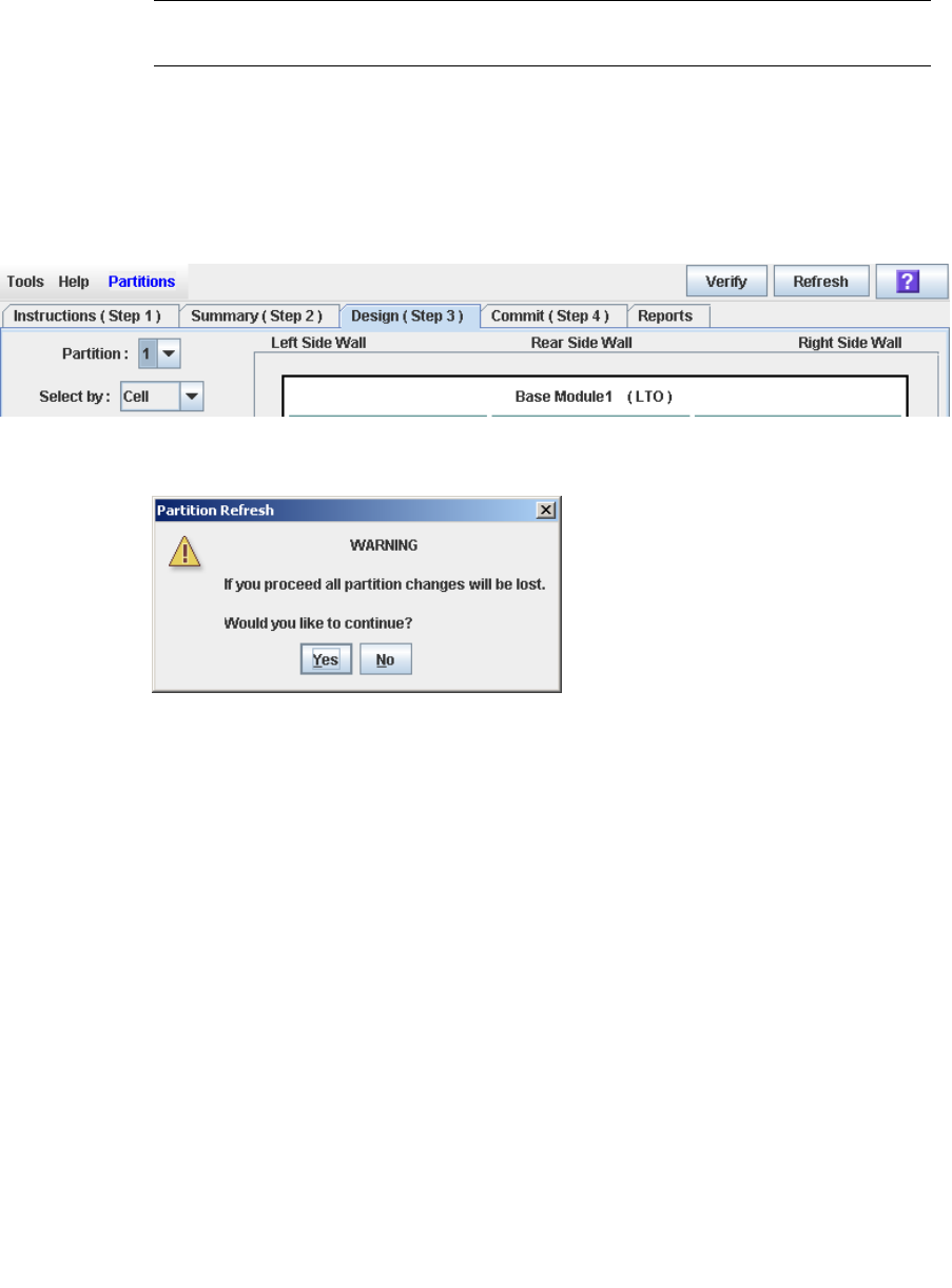
Partition Management Tasks
178 SL500 User’s Guide • July 2008 Revision: KA • 96116
▼ Refresh the SL Console Partition Workspace
Use this procedure to refresh the SL Console partition workspace with current data
from the library controller database. The current data includes all updates that other
users have made to the library controller database during your login session, through
the command line interface, other SL Console sessions, or host applications.
Note – After you complete this procedure, all uncommitted partition changes you have
made during this SL Console login session are discarded.
1. Select Tools > Partitions.
2. Click one of the following tabs:
■Summary (Step 2)
■Design (Step 3)
The selected screen appears.
3. In the Options Bar, click Refresh.
The Partition Refresh popup appears.
4. Click Yes to confirm the refresh.
All partition screen data is updated with current data from the library controller
database.

Partition Management Tasks
96116 • Revision: KA Chapter 6 Library Partitioning 179
▼ Reallocate Library Resources
Reallocating library resources (storage cells, tape drives, CAP cells, or cartridges) from
one partition to another is done through the Design (Step 3) screen. You must use the
following two-step process:
1. Remove the resource from the partition it is currently allocated to.
2. Allocate the resource to a different partition.
See “Design a Partition” on page 162 for detailed instructions.
Caution – Reallocating resources can result in orphaned cartridges and data that could
be lost. See “Orphaned Cartridges in Partitioned Libraries” on page 152 for details.
Partition Management Tasks
180 SL500 User’s Guide • July 2008 Revision: KA • 96116
▼ Make a Hardware Change to a Partitioned Library
Some library hardware changes, such as adding expansion modules, or adding CAP
cells, may require the removal of all or part of an existing partitioned module. Use the
following process to make such hardware changes without losing partitioning
information for the sections of the library that are unchanged.
Caution – Failure to follow this procedure could result in the loss of library partition
configuration information after a hardware change.
1. De-allocate all library resources (storage cells, CAPs, and drives) that will be
removed as part of the hardware change from the partitions they are currently
allocated to.
See “Design a Partition” on page 162 for detailed instructions.
2. Power down the library.
See “Power Down the Library” on page 353 for detailed instructions.
3. Install the hardware change.
4. Power up the library.
See “Power Up the Library” on page 354 for detailed instructions.
All partition allocations for the unchanged parts of the library remain in effect.
5. Allocate the library resources that have been added due to the hardware change.
See “Design a Partition” on page 162 for detailed instructions.
Caution – Reallocating resources can result in orphaned cartridges and data that could
be lost. See “Orphaned Cartridges in Partitioned Libraries” on page 152 for details.

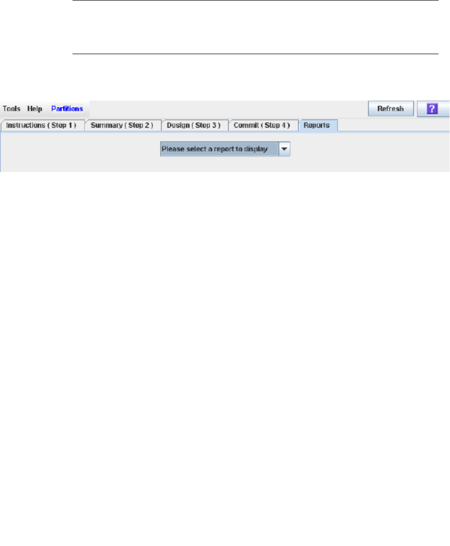
Partition Report Tasks
182 SL500 User’s Guide • July 2008 Revision: KA • 96116
▼ Display a Partition Report
Use this procedure to display any of the following partition reports:
■Cartridge Cell and Media Summary—Displays a detailed list of all resource partition
assignments.
■Host Connections Summary—Displays detailed host-partition connection
information for all partitions.
■Orphaned Cartridge Report—Displays a detailed list of all orphaned cartridges.
■Partition Details—Displays detailed information for a selected partition.
■Partition Summary—Displays summary information for all partitions.
Note – The partition reports display data saved to the library controller database. If
you have made partition configuration changes without commiting the changes to the
library controller through the Commit (Step 4) screen, the data in these reports will
differ from data shown on the partition Summary (Step 2) and Design (Step 3) screens.
1. Select Tools > Partitions, and click the Reports tab.
The Reports screen appears.
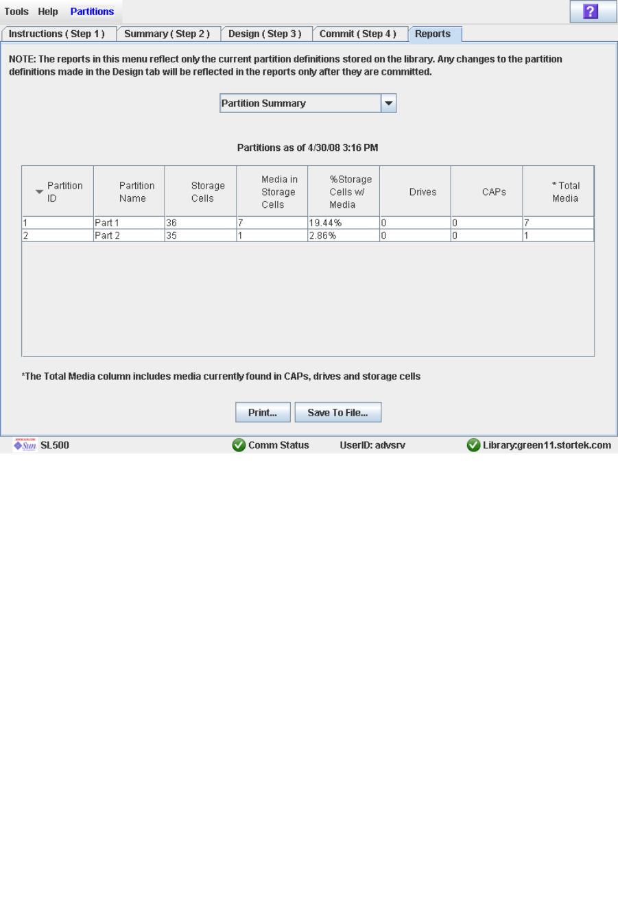
Partition Report Tasks
96116 • Revision: KA Chapter 6 Library Partitioning 183
2. In the pull-down menu, select the report you want to display.
The screen is updated with current data from the library controller database.
3. If you want to print the report data or save it to a file, see the following procedures:
■“Print Partition Report Data” on page 184
■“Save Partition Report Data” on page 185
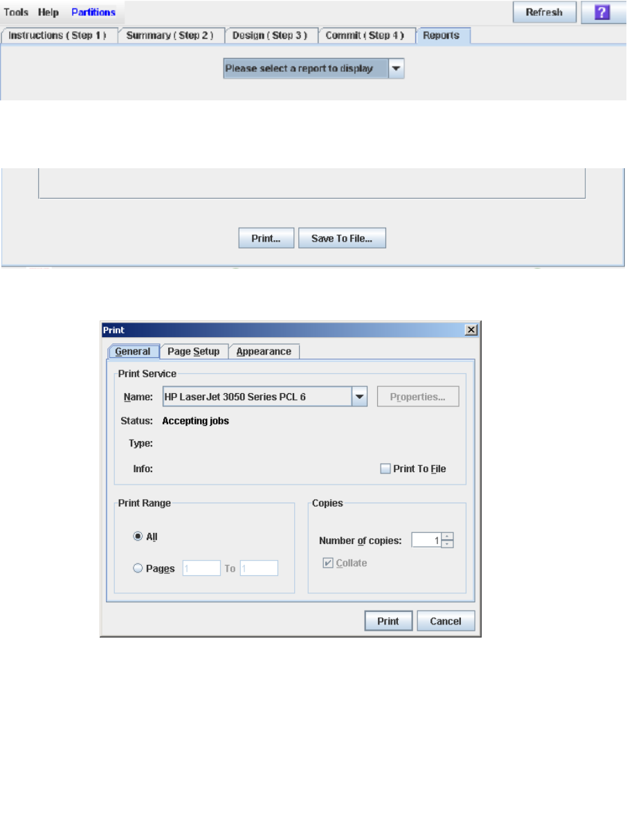
Partition Report Tasks
184 SL500 User’s Guide • July 2008 Revision: KA • 96116
▼ Print Partition Report Data
Use this procedure to print a partition report. This procedure can be performed from
any of the partition report screens.
1. Select Tools > Partitions, and click the Reports tab.
The Reports screen appears.
2. In the pull-down menu, select any report.
The specified report is displayed. All report screens include the Print and Save to File
buttons.
3. Click Print.
The Print popup appears.
4. Complete the print popup, and click Print.
The report is printed to the selected printer.
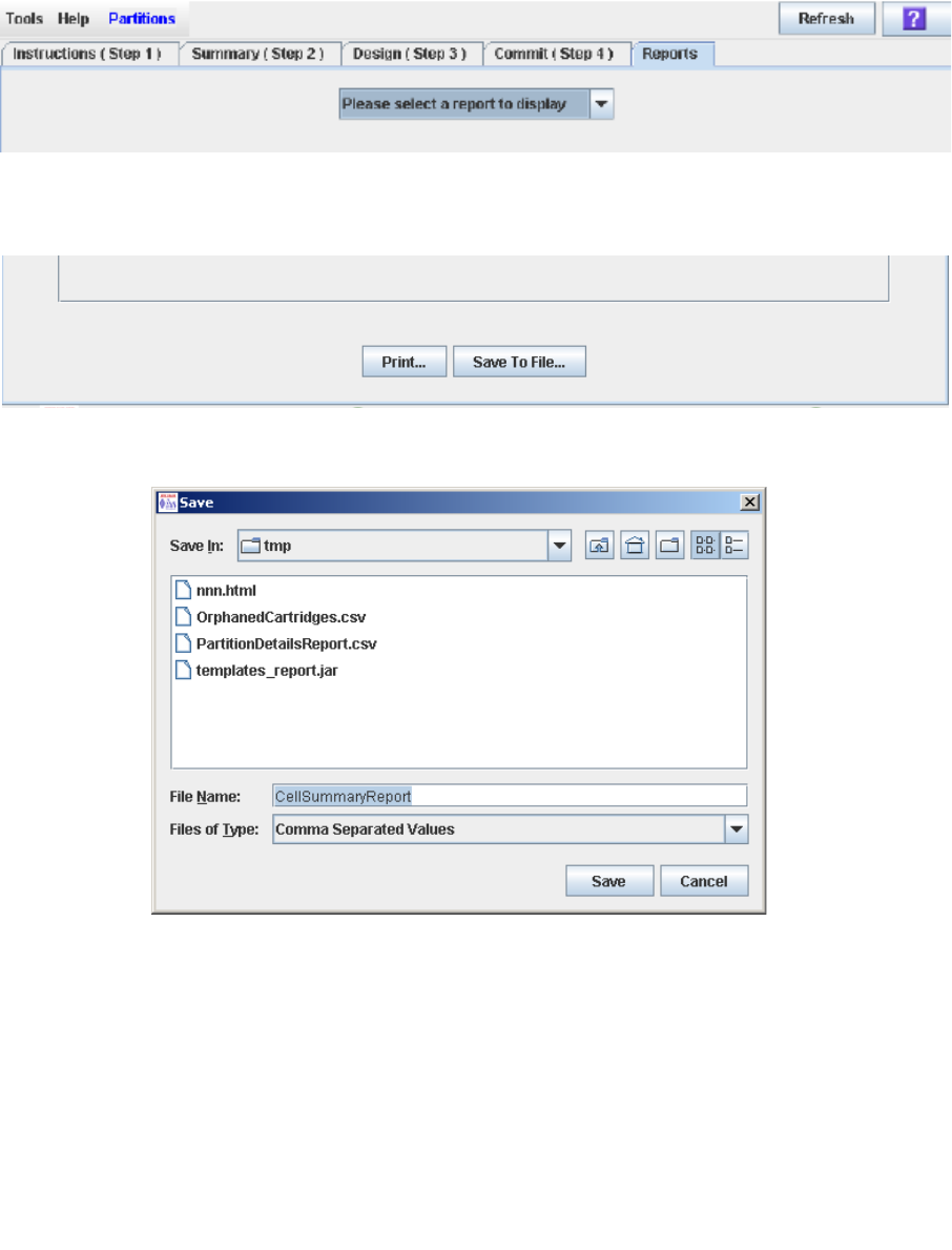
Partition Report Tasks
96116 • Revision: KA Chapter 6 Library Partitioning 185
▼ Save Partition Report Data
Use this procedure to save partition report data to a comma-separated file (.csv
format). You can use a variety of spreadsheet applications to view the file. This
procedure can be performed from any of the partition report screens.
1. Select Tools > Partitions, and click the Reports tab.
The Reports screen appears.
2. In the pull-down menu, select any report.
The specified report is displayed. All report screens include the Print and Save to File
buttons.
3. Click Save to File.
The Save popup appears.
4. Browse to the directory where you want to save the file, and enter the file name.
5. Click Save.
The data is saved to the specified file.

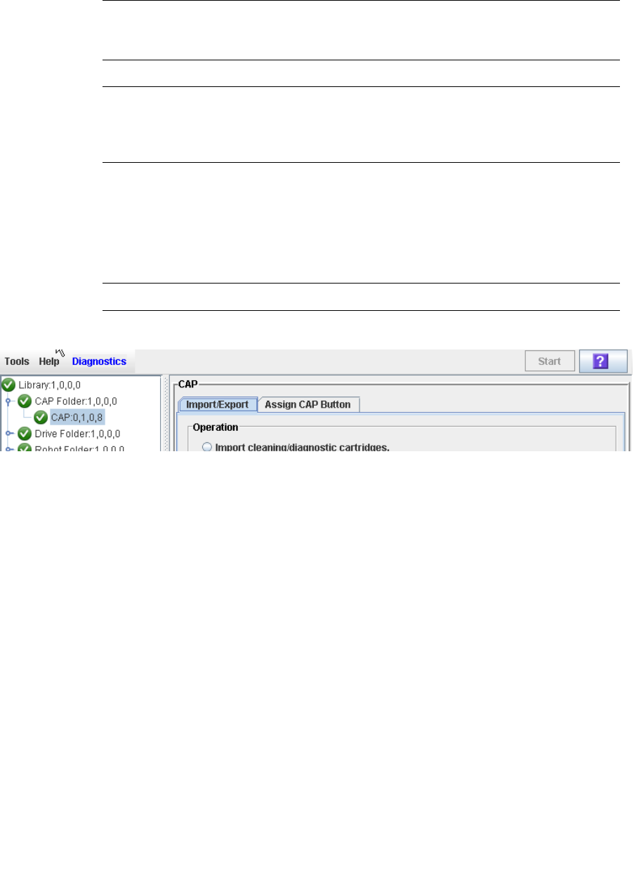
CAP Operation Tasks
96116 • Revision: KA Chapter 6 Library Partitioning 187
▼ Enter Cartridges Into a Partitioned Library
Use this procedure to enter cartridges into a partitioned library. Partitions with no
allocated CAP cells must use common CAP cells. Partitions with allocated CAP cells
must use the cells allocated to them.
Note – This procedure highlights aspects of CAP operations that are unique to
partitioned libraries. For general enter and eject procedures, see “Chapter 3, Library
Operation.”
Note – Although it is possible to enter cartridges through a CAP without using the
Assign CAP Button screen, it is recommended that you access the screen first to verify
the partition settings. This will help to prevent cartridges from being entered
inadvertently into the wrong partition.
1. Initiate the enter operation at the host. See the appropriate tape management
software documentation for the procedures and commands.
2. Select Tools > Diagnostics.
3. Expand the CAP Folder, and click the CAP you want to use.
Note – In a partitioned library, only one CAP is listed in the Diagnostics CAP Folder.
The Import/Export screen appears.
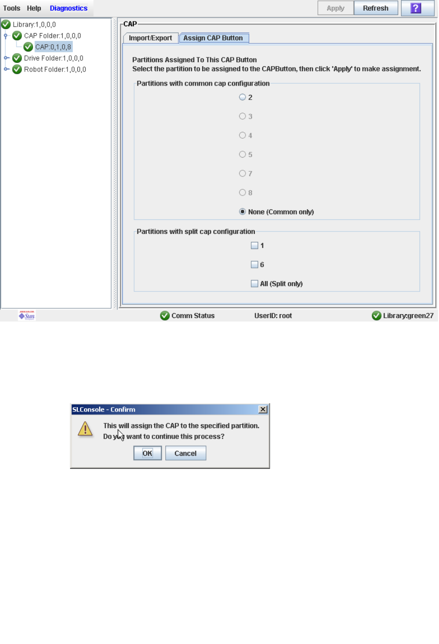
CAP Operation Tasks
188 SL500 User’s Guide • July 2008 Revision: KA • 96116
4. Click the Assign CAP Button tab.
The Assign CAP Button screen appears.
5. In the Common CAP and Split CAP tables, click the partitions into which you want
to enter cartridges. See “Diagnostics > CAP—Assign CAP Button” on page 245 for
details on these screen fields.
6. Click Apply.
The CAP Confirm popup appears.
7. Click OK.
8. Depending on how your library’s CAPs are configured, this operation may expose
CAP cells that are not accessible to the requesting host’s partition. For example,
because a split CAP can contain common cells or cells allocated to multiple
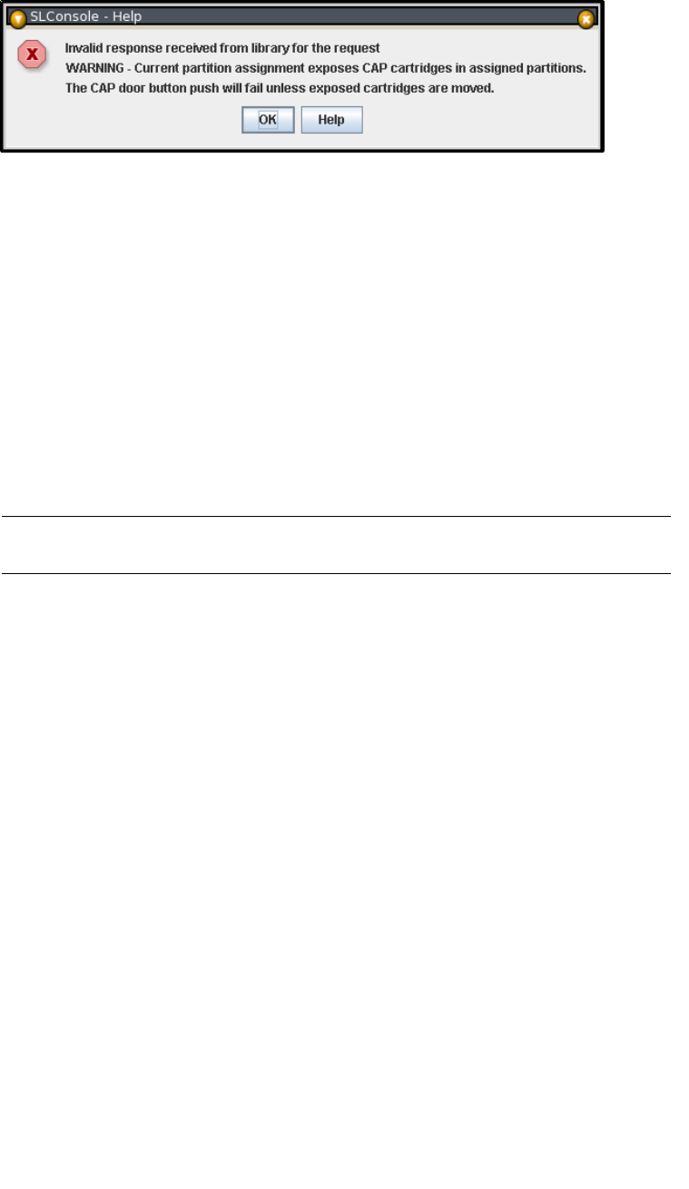
CAP Operation Tasks
96116 • Revision: KA Chapter 6 Library Partitioning 189
partitions, opening the CAP door may expose cells not allocated to the selected
partition. If any of the inaccessible cells contain cartridges, the CAP door will not
open, and a warning popup appears.
Click OK to return to the Assign CAP Button screen. Before you can continue with this
procedure, you must remove the inaccessible cartridges from the CAP.
9. On the library control panel, push the CAP Open button.
10.The library opens the doors of all CAPs with cells accessible to the selected partition.
Doors to CAPs that contain only inaccessible cells do not open.
The library also sends CAP status messages to all hosts with access to the exposed cells.
Following are examples:
■If the library opens common CAPs only, messages are sent to all hosts with access to
common CAP cells.
■If the library opens a split CAP containing both allocated and common cells,
messages are sent to all hosts in the assigned partitions, as well as all hosts with
access to common CAP cells.
11.Place the cartridges in any CAP cells that are accessible to the selected partition.
Note – If you place cartridges in cells that are not accessible to the selected partition,
the CAP door will not lock. You must move the cartridges to the appropriate CAP cells.
12.Close the CAP. It locks automatically.
13.Move the cartridges from the CAP to storage cells within the selected partition. See
the appropriate tape management software documentation for the procedures and
commands.
14.Once the selected partitions are finished with the CAP, it is recommended that you
restore the Assign CAP Button screen to the following settings. This will help to
prevent cartridges from being entered inadvertently into the wrong partition in the
next CAP operation.
■In the Common CAP table, click None.
■In the Split CAP table, clear all the checkboxes.
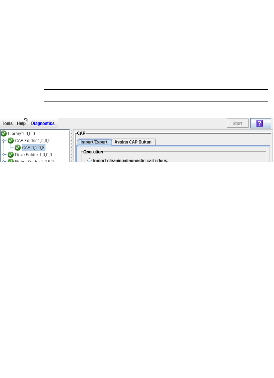
CAP Operation Tasks
190 SL500 User’s Guide • July 2008 Revision: KA • 96116
▼ Eject Cartridges From a Partitioned Library
Use this procedure to eject cartridges from a partitioned library. Partitions with no
allocated CAP cells must use common CAP cells. Partitions with allocated CAP cells
must use the cells allocated to them.
Note – This procedure highlights aspects of CAP operations that are unique to
partitioned libraries. For general enter and eject procedures, see “Chapter 3, Library
Operation.”
1. Initiate the eject operation at the host. See the appropriate tape management
software documentation for the procedures and commands.
2. The HandBot places the cartridges into CAP cells accessible to the host.
3. Select Tools > Diagnostics.
4. Expand the CAP Folder, and click the CAP you want to use.
Note – In a partitioned library, only one CAP is listed in the Diagnostics CAP Folder.
The Import/Export screen appears.
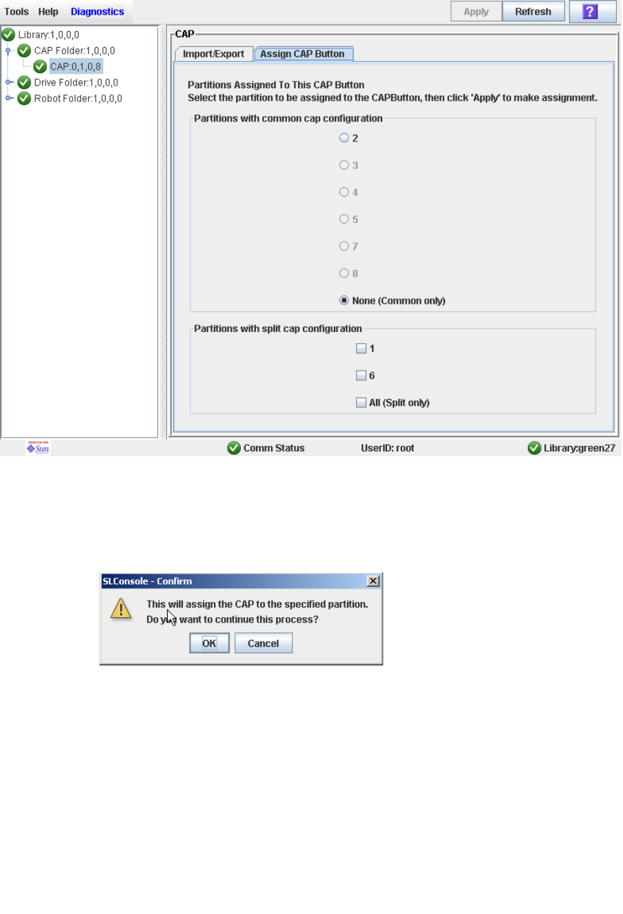
CAP Operation Tasks
96116 • Revision: KA Chapter 6 Library Partitioning 191
5. Click the Assign CAP Button tab.
The Assign CAP Button screen appears.
6. In the Common CAP and Split CAP tables, click the partitions from which you are
ejecting cartridges. See “Diagnostics > CAP—Assign CAP Button” on page 245 for
details on these screen fields.
7. Click Apply.
The CAP Confirm popup appears.
8. Click OK.
9. Depending on how your library’s CAPs are configured, this operation may expose
CAP cells that are not accessible to the requesting host’s partition. For example,
because a split CAP can contain common cells or cells allocated to multiple
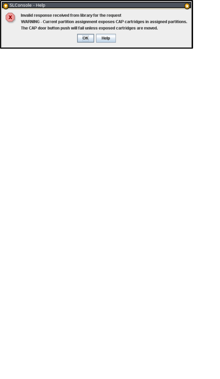
CAP Operation Tasks
192 SL500 User’s Guide • July 2008 Revision: KA • 96116
partitions, opening the CAP door may expose cells not allocated to the selected
partition. If any of the inaccessible cells contain cartridges, the CAP door will not
open and a warning popup appears.
Click OK to return to the Assign CAP Button screen. Before you can continue with this
procedure, you must remove the inaccessible cartridges from the CAP.
10.On the library control panel, push the CAP Open button.
11.The library opens the doors of all CAPs with cells accessible to the selected partition.
Doors to CAPs that contain only inaccessible cells do not open.
The library also sends CAP status messages to all hosts with access to the exposed cells.
Following are examples:
■If the library opens common CAPs only, messages are sent to all hosts with access to
common CAP cells.
■If the library opens a split CAP containing both allocated and common cells,
messages are sent to all hosts in the assigned partitions, as well as all hosts with
access to common CAP cells.
12.Remove the cartridges from the CAP cells.
13.Close the CAP. It locks automatically.
14.Once the selected partitions are finished with the CAP, it is recommended that you
restore the Assign CAP Button screen to the following settings. This will help to
prevent cartridges from being entered inadvertently into the wrong partition in the
next CAP operation.
■In the Common CAP table, click None.
■In the Split CAP table, clear all the checkboxes.

Partition Screen Reference
96116 • Revision: KA Chapter 6 Library Partitioning 193
Partition Screen Reference
This section includes detailed descriptions of all SL Console partition screens, arranged
by screen navigation path. For example,
Partitions—Summary (Step 2)—Add Connection indicates the screen accessed by
clicking Tools and then Partitions from the Menu Bar, and then clicking the Summary
(Step 2) tab, and then the Add Connection button.
Note – The Partitions screens can be accessed only from the standalone SL Console or
the Web-launched SL Console. They are not available on the local operator panel.
Partition Screens are organized into the following categories:
■“Partition Summary Screens” on page 194
■“Partition Design and Commit Screens” on page 211
■“Partition Report Screens” on page 226
■“Partition CAP Operation Screens” on page 244
Note – The partition Summary (Step 2) and Design (Step 3b) screens, and all
associated popups, give you a dynamic workspace to design your library partitions. All
partition configuration information is automatically saved to the partition workspace in
SL Console memory and retained for the duration of your SL Console session. This
allows you to switch among partition views and leave and return to the partition
screens any number of times without losing your configuration changes.
Caution – Information in the SL Console partition workspace is saved to the library
controller database only through the Commit (Step 4) screen. If your SL Console
session ends or you refresh the workspace data before you have committed your
updates through the Commit (Step 4) screen, you will lose any partition changes you
have made through the Summary (Step 2) and Design (Step 3b) screens and all
associated popups.

Partition Summary Screens
194 SL500 User’s Guide • July 2008 Revision: KA • 96116
Partition Summary Screens
Partitions—Instructions (Step 1)
Partitions—Summary (Step 2)
Partitions—Summary (Step 2)—Add Connection
Partitions—Summary (Step 2)—Delete Connection
Partitions—Summary (Step 2)—Modify Connection
Partitions—Summary (Step 2)—Add Partition
Partitions—Summary (Step 2)—Delete Partition
Partitions—Summary (Step 2)—Modify Partition
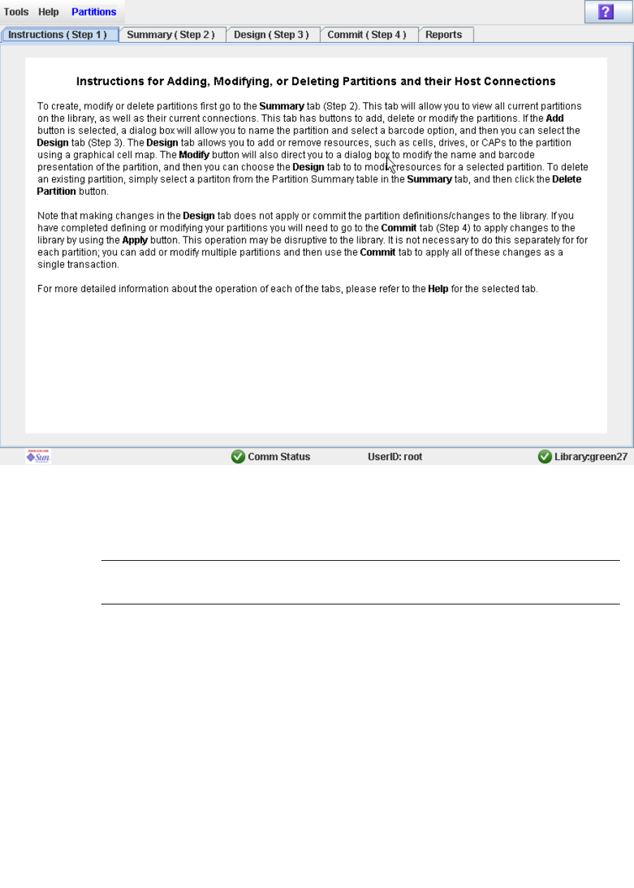
Partition Summary Screens
96116 • Revision: KA Chapter 6 Library Partitioning 195
Partitions—Instructions (Step 1)
Sample Screen
Description
Displays instructions for using the partition screens.
Note – This screen appears automatically the first time you select Tools > Partitions
during an SL Console login session.
Screen Fields
None
Buttons
? (Help)
Click to display online help for the screen.

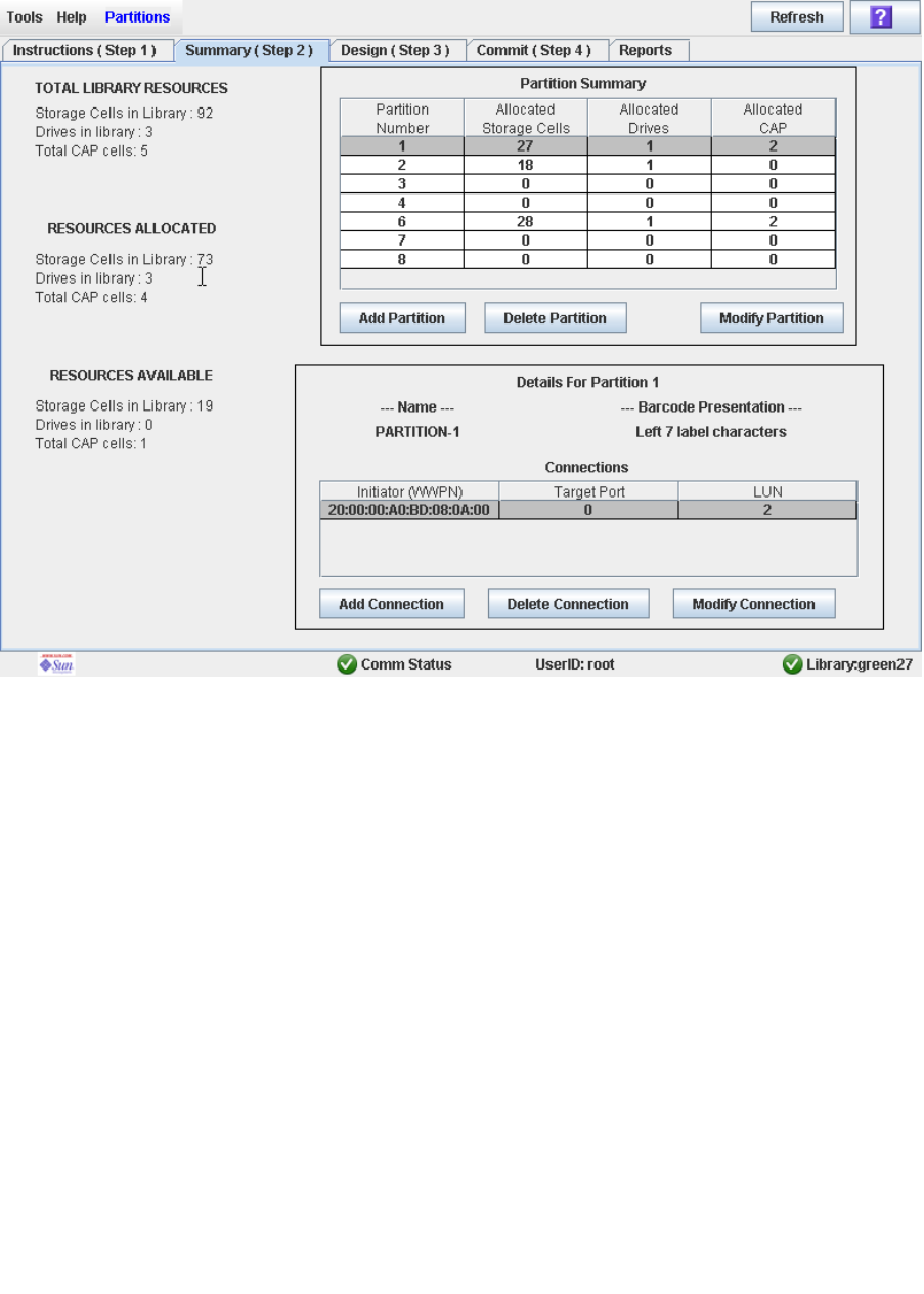
Partition Summary Screens
96116 • Revision: KA Chapter 6 Library Partitioning 197
Partitions—Summary (Step 2)
Sample Screen
Description
Displays summary information for the library and, optionally, a selected partition.
Also includes buttons that allow you to initiate any of the following activities:
■Add a new partition
■Delete a partition from the library
■Modify partition summary information
■Add a new host-partition connection
■Delete a host-partition connection
■Modify the configuration of a host-partition connection

Partition Summary Screens
198 SL500 User’s Guide • July 2008 Revision: KA • 96116
Screen Fields
Partition Summary
Partition Number
Display only.
ID assigned to the partition. IDs can range from 1–8.
Allocated Storage Cells
Display only.
Total number of storage cells allocated to this partition.
Allocated Drive Bays
Display only.
Total number of tape drives allocated to this partition.
Allocated CAP Cells
Display only.
Total number of individual CAP cells allocated to this partition.
Host-Partition Connection Summary
Note – The following fields display host-partition connection information for the
partition currently selected in the Partition Summary table.
Name
Display only.
Name assigned to the selected partition.
Library controller bar code presentation
Display only.
Tape cartridge bar code format assigned to the selected partition.
Initiator (WWPN)
Display only.
World Wide Port Name of the host bus adapter (HBA).
Target Port
Display only.
Port number of the SL500 library controller. This entry is always “0”.
LUN
Display only.
Logical unit number of the library partition on the host. This entry must be unique
on the host.

Partition Summary Screens
96116 • Revision: KA Chapter 6 Library Partitioning 199
TOTAL LIBRARY RESOURCES
Storage Cells in Library
Display only.
Total physical capacity of the library.
Drive Bays in Library
Display only.
Total number of tape drives in the library.
Total CAP cells
Display only.
Total number of CAP cells in the library.
TOTAL RESOURCES ALLOCATED
Storage Cells in Library
Display only.
Total number of storage cells allocated to all library partitions
Drive Bays in Library
Display only.
Total number of tape drives allocated to all library partitions.
Total CAP cells
Display only.
Total number of CAP cells allocated to all library partitions.
TOTAL RESOURCES AVAILABLE
Storage Cells in Library
Display only.
Total number of storage cells in the library that are not allocated to any partition.
Drive Bays in Library
Display only.
Total number of tape drives in the library that are not allocated to any partition.
Total CAP cells
Display only.
Total number of CAP cells in the library that are not allocated to any partition.

Partition Summary Screens
200 SL500 User’s Guide • July 2008 Revision: KA • 96116
Buttons
Refresh
Click to refresh the SL Console partition workspace with current data from the
library controller database. All uncommitted partition changes you have made
during this SL Console login session will be discarded. The Partition Refresh popup
appears, prompting you to confirm the refresh.
? (Help)
Click to display online help for the screen.
Add Partition
Click to add a new partition. The Partitions—Summary (Step 2)—Add Partition
popup appears.
Delete Partition
Click to delete the currently selected partition. The Partitions—Summary
(Step 2)—Delete Partition popup appears.
Modify Partition
Click to modify summary information for the currently selected partition. The
Partitions—Summary (Step 2)—Modify Partition popup appears.
Add Connection
Click to add a new host connection to the currently selected partition. The
Partitions—Summary (Step 2)—Add Connection popup appears.
Delete Connection
Click to delete the currently selected host-partition connection. The
Partitions—Summary (Step 2)—Delete Connection popup appears.
Modify Connection
Click to modify the configuration of the currently selected host-partition connection.
The Partitions—Summary (Step 2)—Modify Connection popup appears.
See Also
■Partitions—Summary (Step 2)
■Partitions—Summary (Step 2)—Add Partition
■Partitions—Summary (Step 2)—Delete Partition
■Partitions—Summary (Step 2)—Modify Partition
■Partitions—Summary (Step 2)—Add Connection
■Partitions—Summary (Step 2)—Delete Connection
■Partitions—Summary (Step 2)—Modify Connection
■Partitions—Design (Step 3)
■Partitions—Commit (Step 4)
■Partitions—Reports
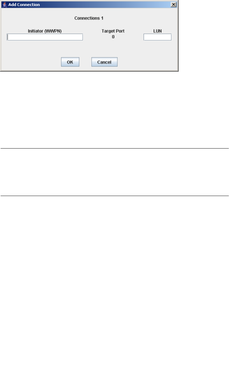
Partition Summary Screens
96116 • Revision: KA Chapter 6 Library Partitioning 201
Partitions—Summary (Step 2)—Add Connection
Sample Screen
Description
Allows you to configure the connection between a host and the selected partition. Each
partition can have up to nine host-partition connections, each one having a unique
LUN.
This screen is a popup that appears when you click Add Connection on the
Partitions—Summary (Step 2) screen.
Caution – Information in the SL Console partition workspace is saved to the library
controller database only through the Commit (Step 4) screen. If your SL Console
session ends or you refresh the workspace data before you have committed your
updates through the Commit (Step 4) screen, you will lose any partition changes you
have made through the Summary (Step 2) and Design (Step 3) screens and all
associated popups.
Screen Fields
Connections n
Display only.
Partition ID of the selected partition.
Initiator (WWPN)
Required.
World Wide Port Name of the host bus adapter (HBA).
Sixteen hexadecimal digits. You can enter upper- or lower-case hex digits, but the
display is always shown in all upper-case.
Target Port
Display only.
Port number of the SL500 library controller. This entry is always “0”.

Partition Summary Screens
202 SL500 User’s Guide • July 2008 Revision: KA • 96116
LUN
Required.
Logical unit number of the library partition on the host. This entry must be unique
on the host. You can create up to nine unique LUNs per partition.
Note – Each initiator connected to the library must have one library partition assigned
to LUN 0. When you verify or commit partition configuration changes, the SL Console
will notify you if an initiator does not meet this requirement.
Buttons
OK
Click to update the SL Console partition workspace with the current screen settings
and return to the previous screen.
Note – Clicking this button does not update the library controller database.
Cancel
Click to discard the current screen settings and return to the previous screen.
See Also
■Partitions—Summary (Step 2)
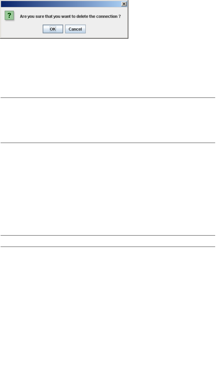
Partition Summary Screens
96116 • Revision: KA Chapter 6 Library Partitioning 203
Partitions—Summary (Step 2)—Delete Connection
Sample Screen
Description
Allows you to delete the selected host-partition connection.
This screen is a popup that appears when you click Delete Connection on the
Partitions—Summary (Step 2) screen.
Caution – Information in the SL Console partition workspace is saved to the library
controller database only through the Commit (Step 4) screen. If your SL Console
session ends or you refresh the workspace data before you have committed your
updates through the Commit (Step 4) screen, you will lose any partition changes you
have made through the Summary (Step 2) and Design (Step 3) screens and all
associated popups.
Screen Fields
None
Buttons
OK
Click to update the SL Console partition workspace with the current screen settings
and return to the previous screen.
Note – Clicking this button does not update the library controller database.
Cancel
Click to discard the current screen settings and return to the previous screen.
See Also
■Partitions—Summary (Step 2)
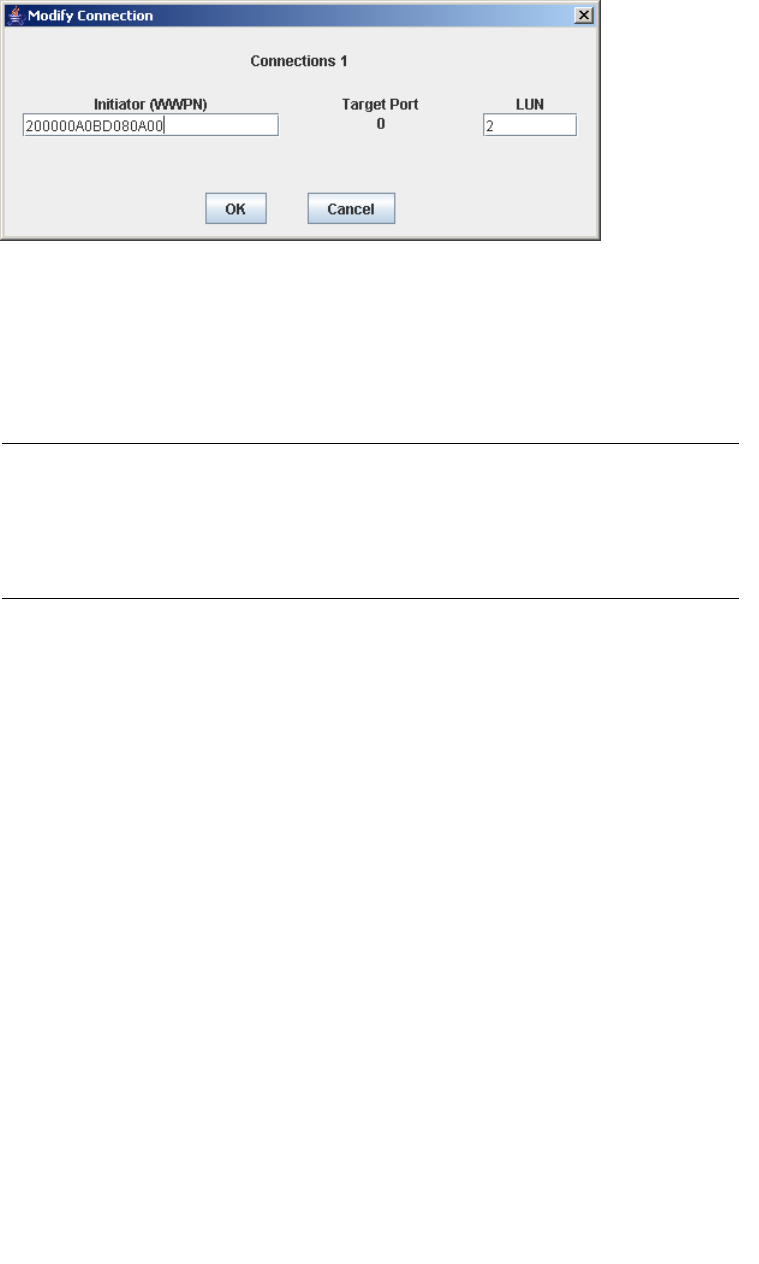
Partition Summary Screens
204 SL500 User’s Guide • July 2008 Revision: KA • 96116
Partitions—Summary (Step 2)—Modify Connection
Sample Screen
Description
Allows you to modify the configuration of the selected host-partition connection.
This screen is a popup that appears when you click Modify Connection on the
Partitions—Summary (Step 2) screen.
Caution – Information in the SL Console partition workspace is saved to the library
controller database only through the Commit (Step 4) screen. If your SL Console
session ends or you refresh the workspace data before you have committed your
updates through the Commit (Step 4) screen, you will lose any partition changes you
have made through the Summary (Step 2) and Design (Step 3) screens and all
associated popups.
Screen Fields
Connections n
Display only.
Partition ID of the selected partition.
Initiator (WWPN)
World Wide Port Name of the host bus adapter (HBA).
Sixteen hexadecimal digits. You can enter upper- or lower-case hex digits, but the
display is always shown in all upper-case.
The screen displays the value assigned previously. You can leave it as is or make
changes.
Target Port
Display only.
Port number of the SL500 library controller. This entry is always “0”.
LUN
Required.

Partition Summary Screens
96116 • Revision: KA Chapter 6 Library Partitioning 205
Logical unit number of the library partition on the host. This entry must be unique
on the host.
Note – Each initiator connected to the library must have one library partition assigned
to LUN 0. When you verify or commit partition configuration changes, the SL Console
will notify you if an initiator does not meet this requirement.
Buttons
OK
Click to update the SL Console partition workspace with the current screen settings
and return to the previous screen.
Note – Clicking this button does not update the library controller database.
Cancel
Click to discard the current screen settings and return to the previous screen.
See Also
■Partitions—Summary (Step 2)
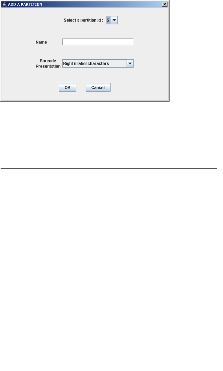
Partition Summary Screens
206 SL500 User’s Guide • July 2008 Revision: KA • 96116
Partitions—Summary (Step 2)—Add Partition
Sample Screen
Description
Allows you to add a new partition. You can create up to eight partitions, with IDs
ranging from 1–8.
This screen is a popup that appears when you click Add Partition on the
Partitions—Summary (Step 2) screen.
Caution – Information in the SL Console partition workspace is saved to the library
controller database only through the Commit (Step 4) screen. If your SL Console
session ends or you refresh the workspace data before you have committed your
updates through the Commit (Step 4) screen, you will lose any partition changes you
have made through the Summary (Step 2) and Design (Step 3) screens and all
associated popups.
Screen Fields
Select a Partition ID
Required.
Partition ID you want to add. Options are 1–8.
The drop-down menu displays all available IDs; the default is the next available ID
in numerical order.
Name
Optional.
Name you want to assign to the partition.
0–60 ASCII characters.

Partition Summary Screens
96116 • Revision: KA Chapter 6 Library Partitioning 207
Barcode Presentation
Required.
Tape cartridge bar code format to be used for the partition.
The drop-down menu displays all available formats previously defined by your Sun
support representative; the default is “Left 6 label characters”.
Buttons
OK
Click to update the SL Console partition workspace with the current screen settings
and return to the previous screen.
Note – Clicking this button does not update the library controller database.
Cancel
Click to discard the current screen settings and return to the previous screen.
See Also
■Partitions—Summary (Step 2)
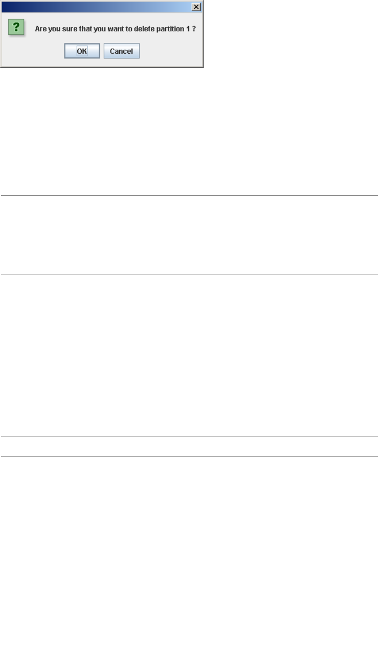
Partition Summary Screens
208 SL500 User’s Guide • July 2008 Revision: KA • 96116
Partitions—Summary (Step 2)—Delete Partition
Sample Screen
Description
Allows you to confirm that you want to delete the specified partition. All information
for the partition—including host-partition connections, partition boundaries, and
partition ID—are deleted from the SL Console partition workspace.
This screen is a popup that appears when you click Delete Partition on the
Partitions—Summary (Step 2).
Caution – Information in the SL Console partition workspace is saved to the library
controller database only through the Commit (Step 4) screen. If your SL Console
session ends or you refresh the workspace data before you have committed your
updates through the Commit (Step 4) screen, you will lose any partition changes you
have made through the Summary (Step 2) and Design (Step 3) screens and all
associated popups.
Screen Fields
None
Buttons
OK
Click to update the SL Console partition workspace with the current screen settings
and return to the previous screen.
Note – Clicking this button does not update the library controller database.
Cancel
Click to discard the current screen settings and return to the previous screen.
See Also
■Partitions—Summary (Step 2)
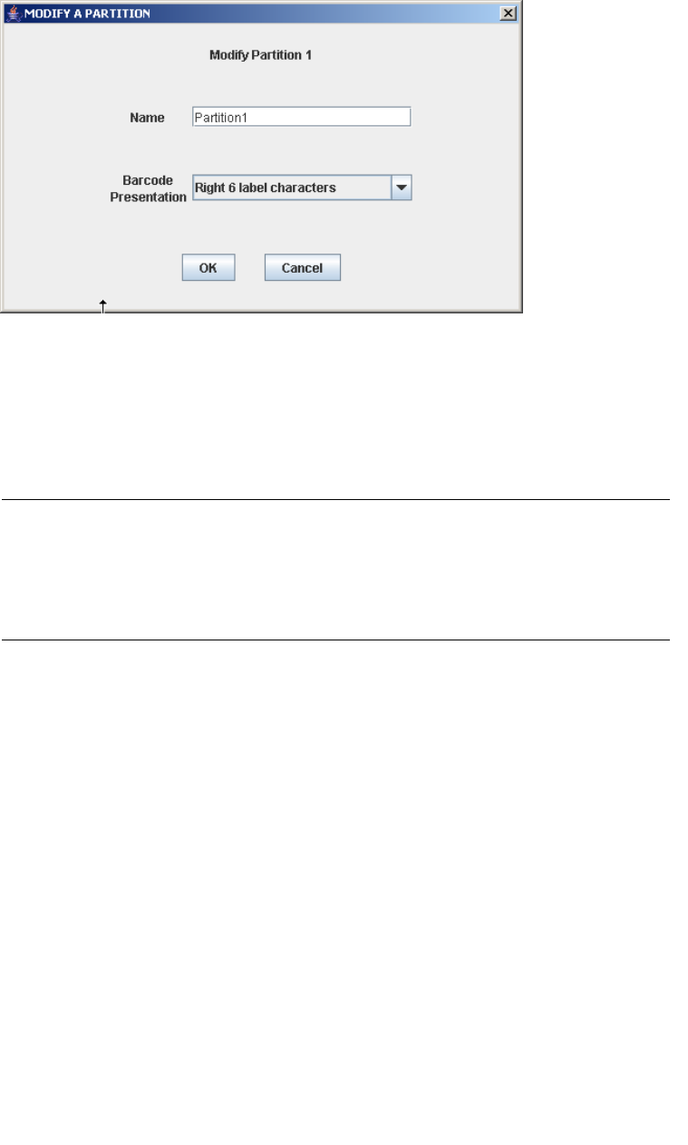
Partition Summary Screens
96116 • Revision: KA Chapter 6 Library Partitioning 209
Partitions—Summary (Step 2)—Modify Partition
Sample Screen
Description
Allows you to modify the name or barcode format of the selected partition.
This screen is a popup that appears when you click Modify Partition on the
Partitions—Summary (Step 2) screen.
Caution – Information in the SL Console partition workspace is saved to the library
controller database only through the Commit (Step 4) screen. If your SL Console
session ends or you refresh the workspace data before you have committed your
updates through the Commit (Step 4) screen, you will lose any partition changes you
have made through the Summary (Step 2) and Design (Step 3) screens and all
associated popups.
Screen Fields
Modify Partition n
Display only.
ID of the partition you want to modify.
Name
Name you want to assign to the partition.
0–60 ASCII characters.
The screen displays the value assigned previously. You can leave it as is or make
changes.
Barcode Presentation
Tape cartridge bar code format to be used for the partition.

Partition Summary Screens
210 SL500 User’s Guide • July 2008 Revision: KA • 96116
The drop-down menu displays all available formats previously defined by your Sun
support representative; the default is “Left 6 label characters”.
The screen displays the value assigned previously. You can leave it as is or make
changes.
Buttons
OK
Click to update the SL Console partition workspace with the current screen settings
and return to the previous screen.
Note – Clicking this button does not update the library controller database.
Cancel
Click to discard the current screen settings and return to the previous screen.
See Also
■Partitions—Summary (Step 2)

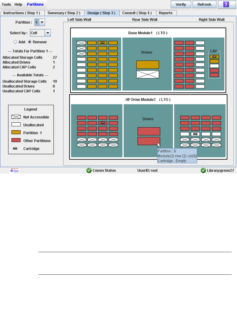
Partition Design and Commit Screens
212 SL500 User’s Guide • July 2008 Revision: KA • 96116
Partitions—Design (Step 3)
Sample Screen
Description
Allows you to define partition boundaries by selecting the resources (storage cells, tape
drives, or CAP cells) you want to include in the partition. You can use any of the
following methods to add or remove resources from a partition (see “Library Map” on
page 215 for detailed instructions):
■Select individual cells or groups of cells
■Select a side within a library module
■Select an entire library module
Caution – Changing partition boundaries can result in orphaned cartridges and data
that could be lost. See “Orphaned Cartridges in Partitioned Libraries” on page 152 for
details.
Partition Design and Commit Screens
96116 • Revision: KA Chapter 6 Library Partitioning 213
Note – The partition Summary (Step 2) and Design (Step 3) screens, and all associated
popups, give you a dynamic workspace to design your library partitions. All partition
configuration information is automatically saved to the partition workspace in
SL Console memory and retained for the duration of your SL Console session. This
allows you to switch among partition views and leave and return to the partition
screens any number of times without losing your configuration changes.
Caution – Information in the SL Console partition workspace is saved to the library
controller database only through the Commit (Step 4) screen. If your SL Console
session ends or you refresh the workspace data before you have committed your
updates through the Commit (Step 4) screen, you will lose any partition changes you
have made through the Summary (Step 2) and Design (Step 3) screens and all
associated popups.
Screen Fields
Partition
Required.
Partition to which you want to add or remove resources (storage cells, tape drives,
or CAP cells).
The drop-down menu displays all valid partition IDs for the library. If no partition
IDs have been defined, the menu is blank.
Note – When you select a partition, the screen is automatically updated to display data
for that partition from the SL Console partition workspace.
Select by
Required.
Indicates the method you want to use for defining partition boundaries. Options are:
■Cell—Select individual or rectangular groups of resources.
■Side—Select all resources, except the CAP, within one side of a library module.
■Module—Select all resources, except the CAP, within a library module.
Note – You must select either Add or Remove.
Add
Required.
Indicates you want to add resources to the partition. You will only be able to click
unallocated resources on the library map.
Remove
Required.
Indicates you want to remove resources from the partition. You will only be able to
click allocated resources on the library map.

Partition Design and Commit Screens
214 SL500 User’s Guide • July 2008 Revision: KA • 96116
Library Totals
Note – The data in these fields is automatically updated from the SL Console partition
workspace when you select a partition.
Allocated Storage Cells
Display only.
Total number of storage cells allocated to the selected partition, based on the
currently defined partition boundaries.
Allocated Drive Bays
Display only.
Total number of tape drives allocated to the selected partition, based on the
currently defined partition boundaries.
Allocated CAP Cells
Display only.
Total number of CAP cells allocated to the selected partition, based on the currently
defined partition boundaries.
Library Totals
Note – The data in these fields is automatically updated from the SL Console partition
workspace when you select a partition.
Unallocated Storage
Display only.
Total number of storage cells in the library that are not allocated to any partition.
Unallocated Drive Bays
Display only.
Total number of tape drives in the library that are not allocated to any partition.
Unallocated CAPs
Display only.
Total number of CAP cells in the library that are not allocated to any partition.
Legend
Legend for the library map. The state of each library resource (storage cell, tape
drive, or CAP cell) is indicated as follows:
■Not Accessible (white and x-ed out). Resource is not accessible to any partition.
Following are some possible reasons:
- Storage cells have been configured for diagnostic cartridges.
■Available (white). Resource is currently not allocated to any partition and
therefore available to the selected partition.
■Partition n (gold). Resource is allocated to the selected partition, partition n.

Partition Design and Commit Screens
96116 • Revision: KA Chapter 6 Library Partitioning 215
■Other Partitions (red). Resource is allocated to another partition and therefore
NOT available to the selected partition.
■Cartridge (cartridge icon). Resource contains a tape cartridge.
Library Map
Graphical representation of the current library configuration. Initial display for the
current SL Console login session is from the library controller database, then the
display reflects data from the SL Console partition workspace as you modify
partition configurations. The display includes the following information:
■Types of modules installed in the library (Base Module, drive module, storage
module)
■Numeric module ID (1–5)
■Media configuration for each module (mixed media or LTO only)
■Location of all resources (storage cells, tape drives, CAP cells) within the library
Note – Move the cursor over any resource to display a tooltip of detailed information
about the cell or drive, its partition assignment, and the identity of any resident
cartridge.
Note – If no partition IDs have been defined, the library map is display only.
Use the library map to modify the boundaries of the selected partition. Depending
on whether you have clicked the Add or Remove radio button, all selected resources
are either added to or removed from the partition.
Depending on your choice in the Select by field, you can perform any of the
following actions.
■Select by cell—Select individual or groups of resources. Resources in a partition
do not need to be adjacent to one another.
- To select an individual resource, double-click it.
- To select a rectangular group of resources, click the cell or drive at one corner
of the rectangle, and then click the cell or drive diagonally opposite.
■Select by side—Select an entire side within a module, except the CAP. Sides in a
partition do not need to be adjacent to one another. To select one side of a library
module, click any resource in that side.
■Select by module—Select an entire module, except the CAP. Modules in a
partition do not have to be adjacent to one another. To select a library module,
click any resource in that module.
Buttons
Verify Results
Click to verify partition configuration changes you have made during this
SL Console login session. The Tools > Partitions—Design (Step 3)—Verify Results
popup appears, indicating whether there are any orphaned cartridges or other errors
in the current partition configuration.

Partition Design and Commit Screens
216 SL500 User’s Guide • July 2008 Revision: KA • 96116
Note – This procedure verifies only one partition at a time. If you need to verify
multiple partitions, you must repeat this procedure separately for each partition.
Note – This verification is performed on the current partition configuration in the
SL Console partition workspace only. It does not verify current partition boundaries
against the library controller database; therefore it cannot identify configuration
conflicts that may arise due to other users performing cartridge movements or library
configuration changes—through the command line interface, other SL Console sessions,
or host applications—at the same time you have made partition changes.
Refresh
Click to refresh the SL Console partition workspace with current data from the
library controller database. All uncommitted partition changes you have made
during this SL Console login session will be discarded. The Partition Refresh popup
appears, prompting you to confirm the refresh.
? (Help)
Click to display online help for the screen.
See Also
■Partitions—Summary (Step 2)
■Partitions—Design (Step 3)—Verify Results
■Partitions—Commit (Step 4)
■Partitions—Reports
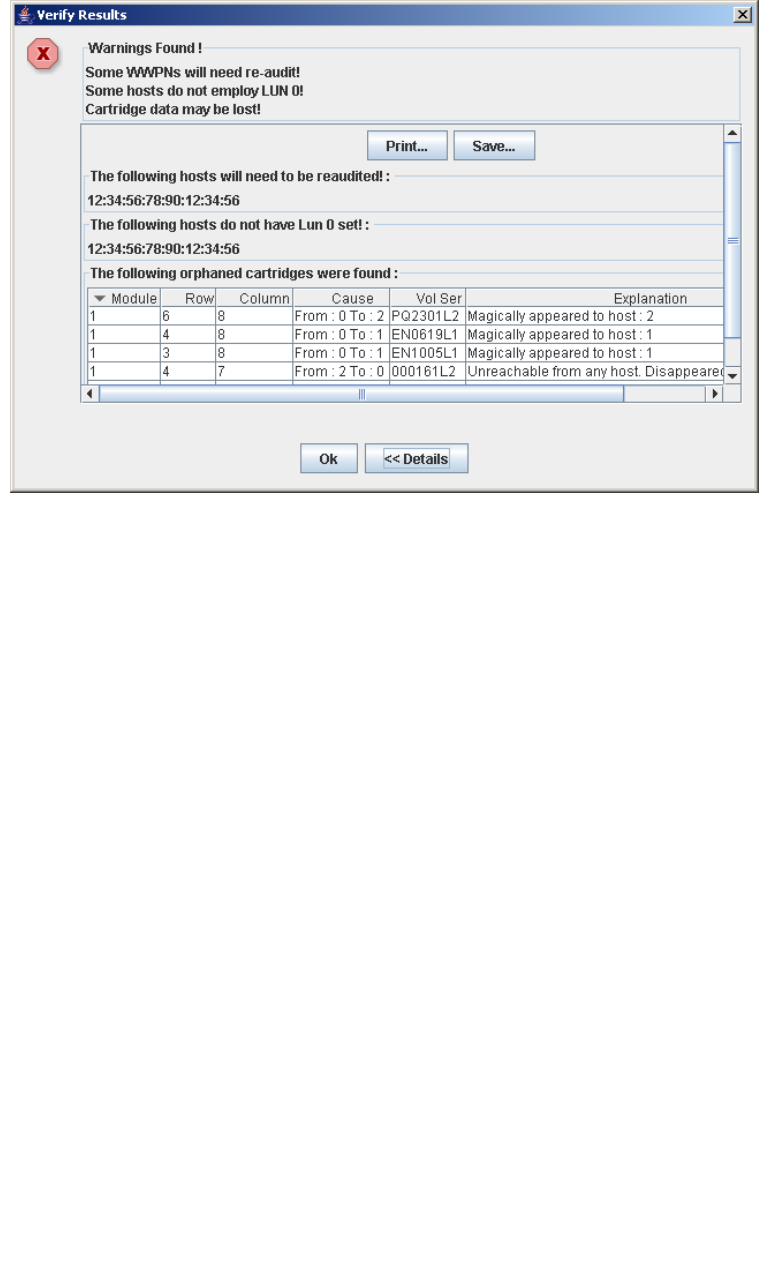
Partition Design and Commit Screens
96116 • Revision: KA Chapter 6 Library Partitioning 217
Partitions—Design (Step 3)—Verify Results
Sample Screen
Description
Displays a list of configuration errors in the current SL Console partition workspace.
This screen is a popup that appears when you click Verify Results on the
Partitions—Design (Step 3) screen.
Possible errors include:
■A partition has orphaned cartridges. See “Orphaned Cartridges in Partitioned
Libraries” for details.
■Library resources have been removed from a partition.
■A host-partition connection does not have a partition assigned to LUN 0 (applies to
FC-SCSI connections only).
If any of these error conditions are present, the screen initially displays summary
warning messages. You can view detailed messages by clicking the Details button.
It is recommended that you resolve all errors before committing the data to the library
controller database.
Optionally, you can print the screen data or save it to a comma-separated file.

Partition Design and Commit Screens
218 SL500 User’s Guide • July 2008 Revision: KA • 96116
Note – The partition Summary (Step 2) and Design (Step 3) screens, and all associated
popups, give you a dynamic workspace to design your library partitions. All partition
configuration information is automatically saved to the partition workspace in
SL Console memory and retained for the duration of your SL Console session. This
allows you to switch among partition views and leave and return to the partition
screens any number of times without losing your configuration changes.
Caution – Information in the SL Console partition workspace is saved to the library
controller database only through the Commit (Step 4) screen. If your SL Console
session ends or you refresh the workspace data before you have committed your
updates through the Commit (Step 4) screen, you will lose any partition changes you
have made through the Summary (Step 2) and Design (Step 3) screens and all
associated popups.
Screen Fields
Note – The screen fields are the same as those displayed in the Partitions—Commit
(Step 4)—Confirm Apply popup.
Warnings found
Display only.
Summary error messages regarding the partition configuration.
The following hosts will need re-audited
Display only.
World Wide Port Names (WWPNs) of any hosts that should re-audit their library
partition. This may be because library resources have been deleted from the
partition.
The following hosts do not have Lun 0 set
Display only.
World Wide Port Names (WWPNs) of any hosts that have not defined any library
partitions as LUN 0 on the host.
The following orphaned cartridges were found
Display only.
Detailed information regarding all orphaned cartridges in the current partition
configuration. Includes module, row, and columnlocation of the cartridge, cartridge
volume serial number (volid), and probable causes and explanations why the
cartridge is orphaned.
Buttons
Print
Click to print the report on a selected printer.

Partition Design and Commit Screens
96116 • Revision: KA Chapter 6 Library Partitioning 219
Save
Click to save the report to a designated comma-separated text file (.csv extension).
Comma-separated files can be opened by a variety of spreadsheet and database
programs.
OK
Click to cancel the update. The library controller database is not updated, but all
partition changes from this login session are retained in the SL Console partition
workspace.
Details
Click to toggle between the expanded and collapsed views of the warning message
display.
See Also
■Partitions—Design (Step 3)
■Partitions—Commit (Step 4)—Confirm Apply
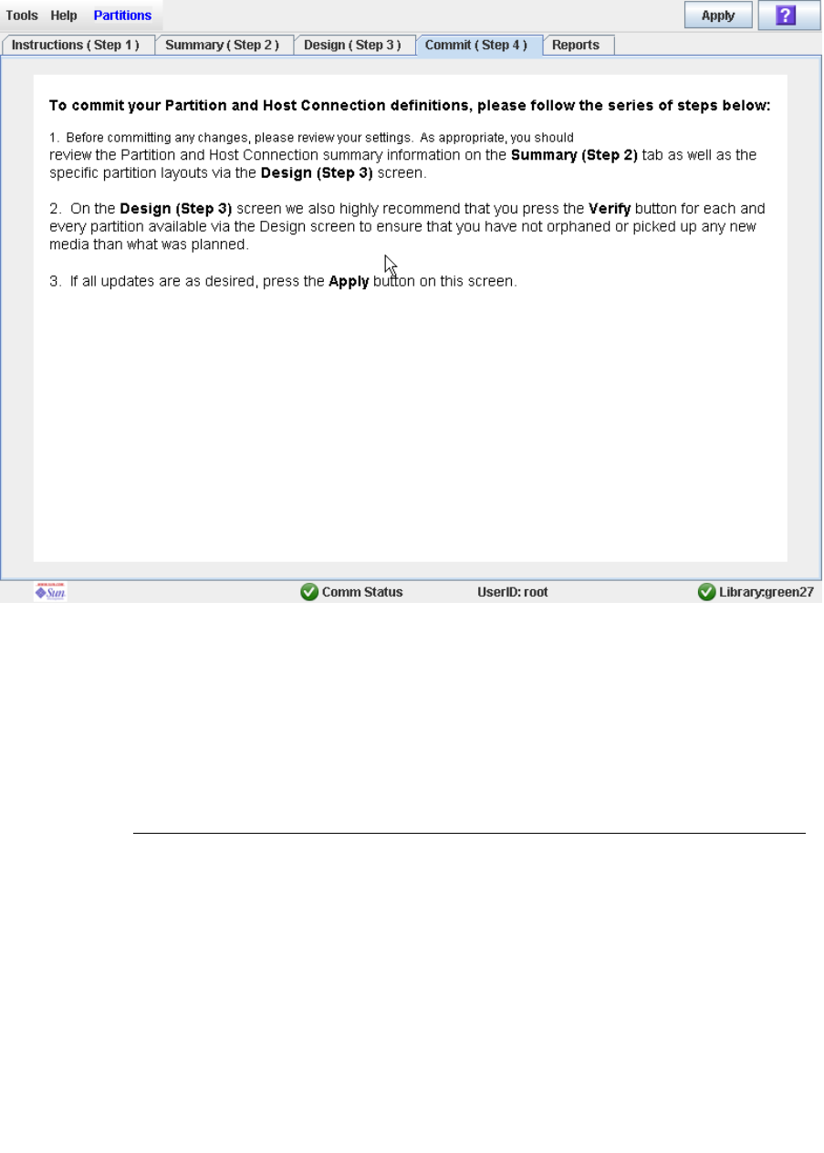
Partition Design and Commit Screens
220 SL500 User’s Guide • July 2008 Revision: KA • 96116
Partitions—Commit (Step 4)
Sample Screen
Description
Allows you to commit all data from the current SL Console partition workspace to the
library controller database. The following data will be committed for all partitions:
■Partition summary information
■Host-partition connection configuration information
■Partition boundary details
Caution – For the following reasons, it is recommended that you make the library
unavailable to other users before committing your partition workspace changes.
There is no real-time validation of partition boundaries against the library controller
database; therefore if you do not make the library unavailable and other users are
performing cartridge movements or library configuration changes, configuration
conflicts may arise. See “Synchronizing the Display With the Controller Database” on
page 31 for details.
Partition Design and Commit Screens
96116 • Revision: KA Chapter 6 Library Partitioning 221
The library temporarily drops all connections to HSC or ACSLS hosts when partition
configurations changes are committed. The hosts will automatically reconnect, but
multiple error messages will be displayed, and cartridge management tasks in progress
may fail.
Caution – Information in the SL Console partition workspace is saved to the library
controller database only through the Commit (Step 4) screen. If your SL Console
session ends or you refresh the workspace data before you have committed your
updates through the Commit (Step 4) screen, you will lose any partition changes you
have made through the Summary (Step 2) and Design (Step 3) screens and all
associated popups.
Caution – It is recommended that you follow the Resolve Orphaned Cartridges
procedure before using this screen.
Caution – This screen updates the library controller database with all partition
configuration changes you have made during this SL Console session. Failure to use
this screen before logging out of the current SL Console session will cause all your
library configuration changes to be lost.
Screen Fields
None
Buttons
Apply
Click to update the library controller database with the current settings from the
SL Console partition workspace. The Tools > Partitions—Commit
(Step 4)—Confirm Apply popup appears, indicating whether there are any
orphaned cartridges or other errors in the current partition configuration.
Note – This button is grayed out if you have not made any changes to the SL Console
partition workspace since the last commit.
? (Help)
Click to display online help for the screen.
See Also
■Partitions—Summary (Step 2)
■Partitions—Design (Step 3)
■Partitions—Design (Step 3)—Verify Results
■Partitions—Commit (Step 4)—Confirm Apply

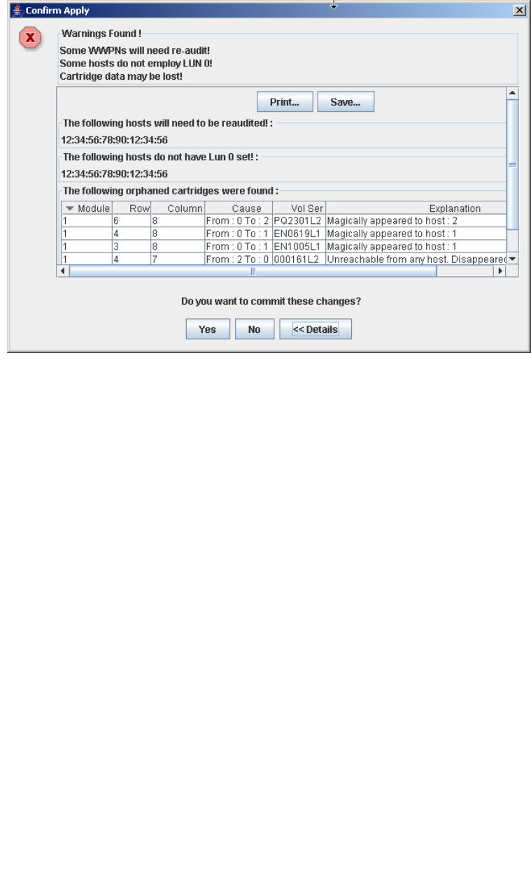
Partition Design and Commit Screens
96116 • Revision: KA Chapter 6 Library Partitioning 223
Partitions—Commit (Step 4)—Confirm Apply
Sample Screen
Description
Displays a list of configuration errors in the current SL Console partition workspace.
This screen is a popup that appears when you click Apply on the
Partitions—Commit (Step 4) screen.
After viewing the error messages, you can commit all data in the SL Console partition
workspace to the library controller database by clicking the Yes button.
Possible errors include:
■A partition has orphaned cartridges. See “Orphaned Cartridges in Partitioned
Libraries” for details.
■Library resources have been removed from a partition.
■A host-partition connection does not have a partition assigned to LUN 0 (applies to
FC-SCSI connections only).
If any of these error conditions are present, the screen initially displays summary
warning messages. You can view detailed messages by clicking the Details button.
It is recommended that you resolve all errors before committing the data to the library
controller database.
Optionally, you can print the screen data or save it to a comma-separated file.

Partition Design and Commit Screens
224 SL500 User’s Guide • July 2008 Revision: KA • 96116
Caution – Information in the SL Console partition workspace is saved to the library
controller database only through the Commit (Step 4) screen. If your SL Console
session ends or you refresh the workspace data before you have committed your
updates through the Commit (Step 4) screen, you will lose any partition changes you
have made through the Summary (Step 2) and Design (Step 3) screens and all
associated popups.
Screen Fields
Note – The screen fields are the same as those displayed in the Partitions—Design
(Step 3)—Verify Results popup.
Warnings found
Display only.
Summary error messages regarding the partition configuration.
The following hosts will need re-audited
Display only.
World Wide Port Names (WWPNs) of any hosts that should re-audit their library
partition. This may be because library resources have been deleted from the
partition.
The following hosts do not have Lun 0 set
Display only.
World Wide Port Names (WWPNs) of any hosts that have not defined any library
partitions as LUN 0 on the host.
The following orphaned cartridges were found
Display only.
Detailed information regarding all orphaned cartridges in the current partition
configuration. Includes module, row, and columnlocation of the cartridge, cartridge
volume serial number (volid), and probable causes and explanations why the
cartridge is orphaned.
Buttons
Print
Click to print the report on a selected printer.
Save
Click to save the report to a designated comma-separated text file (.csv extension).
Comma-separated files can be opened by a variety of spreadsheet and database
programs.
Yes
Click to confirm that you want to update the library controller database with the
current settings from the SL Console workspace.

Partition Design and Commit Screens
96116 • Revision: KA Chapter 6 Library Partitioning 225
No
Click to cancel the update. The library controller database is not updated, but all
partition changes from this login session are retained in the SL Console partition
workspace.
Details
Click to toggle between the expanded and collapsed views of the warning message
display.
See Also
■Partitions—Commit (Step 4)
■Partitions—Design (Step 3)—Verify Results

Partition Report Screens
226 SL500 User’s Guide • July 2008 Revision: KA • 96116
Partition Report Screens
Partitions—Reports
Partitions—Reports—Cartridge Cell and Media Summary
Partitions—Reports—Host Connections Summary
Partitions—Reports—Orphaned Cartridge Report
Partitions—Reports—Partition Details
Partitions—Reports—Partition Summary
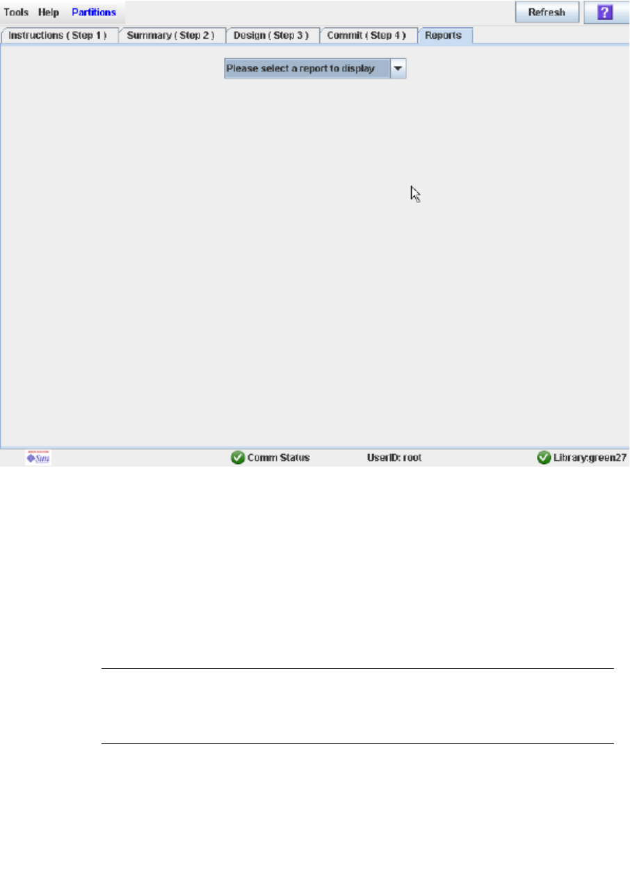
Partition Report Screens
96116 • Revision: KA Chapter 6 Library Partitioning 227
Partitions—Reports
Sample Screen
Description
Allows you to select one of the following library partition reports:
■Cartridge Cell and Media Summary
■Host Connections Summary
■Orphaned Cartridge Report
■Partition Details
■Partition Summary
Note – The partition reports display data saved to the library controller database. If
you have made partition configuration changes without commiting the changes to the
library controller through the Commit (Step 4) screen, the data in these reports will
differ from data shown on the partition Summary (Step 2) and Design (Step 3) screens.

Partition Report Screens
228 SL500 User’s Guide • July 2008 Revision: KA • 96116
Screen Fields
Please select a report to display
Required.
Click the report you want to display. The drop-down menu lists all available library
partition reports.
Buttons
Refresh
Click to refresh the SL Console partition workspace with current data from the
library controller database. All uncommitted partition changes you have made
during this SL Console login session will be discarded. The Partition Refresh popup
appears, prompting you to confirm the refresh.
? (Help)
Click to display online help for the screen.
See Also
■Partitions—Summary (Step 2)
■Partitions—Design (Step 3)
■Partitions—Commit (Step 4)
■Partitions—Reports—Cartridge Cell and Media Summary
■Partitions—Reports—Host Connections Summary
■Partitions—Reports—Orphaned Cartridge Report
■Partitions—Reports—Partition Details
■Partitions—Reports—Partition Summary
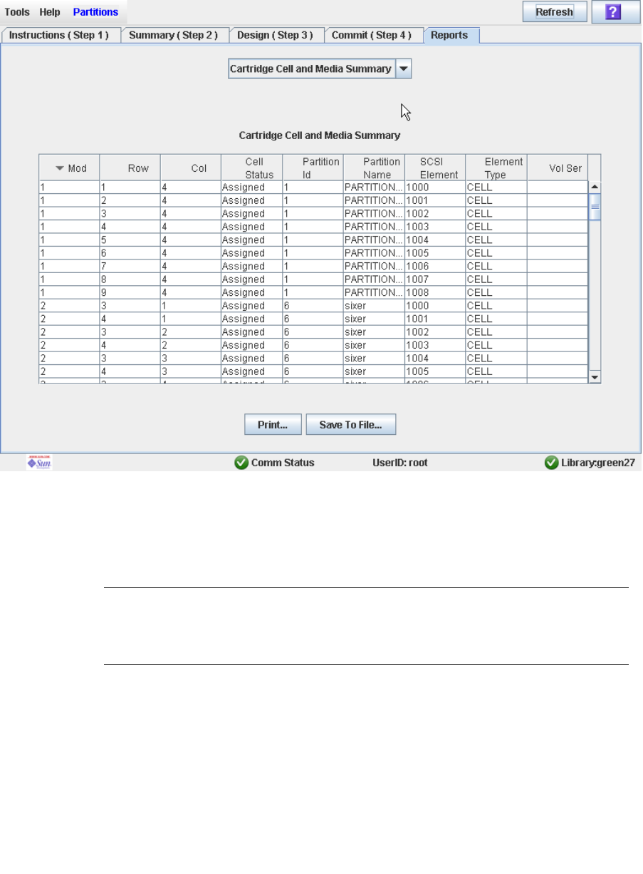
Partition Report Screens
96116 • Revision: KA Chapter 6 Library Partitioning 229
Partitions—Reports—Cartridge Cell and Media
Summary
Sample Screen
Description
Displays detailed information about all library resources (storage cells, tape drives, and
CAP cells) and any stored cartridges.
Note – The partition reports display data saved to the library controller database. If
you have made partition configuration changes without commiting the changes to the
library controller through the Commit (Step 4) screen, the data in these reports will
differ from data shown on the partition Summary (Step 2) and Design (Step 3) screens.
You can modify the layout and display of this screen. See “Modifying the Screen
Layout” on page 32 for details.
Optionally, you can print the screen data or save it to a comma-separated file.

Partition Report Screens
230 SL500 User’s Guide • July 2008 Revision: KA • 96116
Screen Fields
Module
Display only.
Module number where the library resource is located.
Row
Display only.
Row number where the library resource is located. Rows are numbered
consecutively from the top down, with row 1 at the top.
Column
Display only.
Column number where the library resource is located. Column location is referenced
from the center of the drive bays. +1 is to the right of the drive bays; -1 is to the left.
Cell Status
Display only.
Partition status of the library resource. Options are:
■Assigned
■Unassigned
Partition ID
Display only.
Partition ID to which the library resource is allocated, if applicable.
Partition Name
Display only.
Name of the partition to which the library resource is allocated, if applicable. If the
library has no defined partitions, “Non-Partitioned Library” is displayed.
SCSI Element
Display only.
Host SCSI element number assigned to the library resource. SCSI element numbers
are continuous within a partition, even if resources are not adjacent.
Element Type
Display only.
Type of library resource. Options are:
■CAP
■CELL
■DRIVE
Vol Ser
Display only.
Volume serial number (VOLID) of the cartridge resident in the library resource, if
applicable.

Partition Report Screens
96116 • Revision: KA Chapter 6 Library Partitioning 231
Buttons
Print
Click to print the report on a selected printer.
Save to File
Click to save the report to a designated comma-separated text file (.csv extension).
Comma-separated files can be opened by a variety of spreadsheet and database
programs.
Refresh
Click to refresh the SL Console partition workspace with current data from the
library controller database. All uncommitted partition changes you have made
during this SL Console login session will be discarded. The Partition Refresh popup
appears, prompting you to confirm the refresh.
? (Help)
Click to display online help for the screen.
See Also
■Partitions—Reports—Host Connections Summary
■Partitions—Reports—Orphaned Cartridge Report
■Partitions—Reports—Partition Details
■Partitions—Reports—Partition Summary
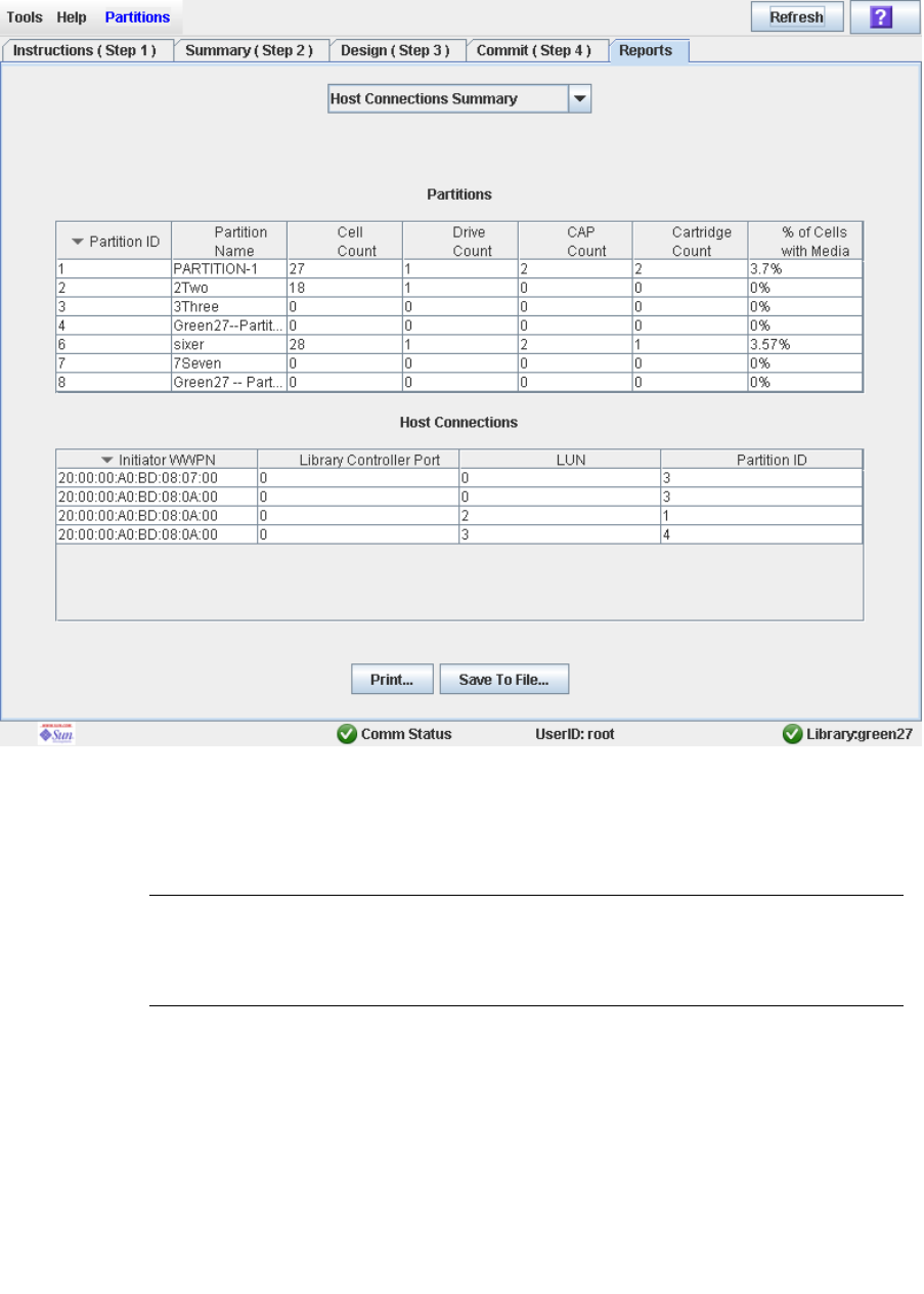
Partition Report Screens
232 SL500 User’s Guide • July 2008 Revision: KA • 96116
Partitions—Reports—Host Connections Summary
Sample Screen
Description
Displays detailed information about all host-partition connections for the library.
Note – The partition reports display data saved to the library controller database. If
you have made partition configuration changes without commiting the changes to the
library controller through the Commit (Step 4) screen, the data in these reports will
differ from data shown on the partition Summary (Step 2) and Design (Step 3) screens.
You can modify the layout and display of this screen. See “Modifying the Screen
Layout” on page 32 for details.
Optionally, you can print the screen data or save it to a comma-separated file.

Partition Report Screens
96116 • Revision: KA Chapter 6 Library Partitioning 233
Screen Fields
Partitions
Note – The screen fields in this section also appear on the
Partitions—Reports—Partition Summary report.
Partition ID
Display only.
ID of the partition (1–8).
Partition Name
Display only.
Name of the partition.
Cell Count
Display only.
Total number of storage cells allocated to the partition.
Drive Count
Display only.
Total number of tape drives allocated to the partition.
CAP Count
Display only.
Total number of CAP cells allocated to the partition.
Cartridge Count
Display only.
Total number of tape cartridges resident in the partition.
% of Cells with Media
Display only.
Percentage of storage cells containing tape cartridges. Calculated as Cartridge Count
/ Cell Count.
Host Connections
Initiator WWPN
Display only.
World Wide Port Name of an host bus adapter (HBA) with a connection to the
partition.
Library Controller Port
Display only.
Port number of the SL500 library controller on the host. This entry is always “0”.

Partition Report Screens
234 SL500 User’s Guide • July 2008 Revision: KA • 96116
LUN
Display only.
Logical unit number of the library partition on the host.
Partition ID
Display only.
Partition ID to which the host has a connection.
Buttons
Print
Click to print the report on a selected printer.
Save
Click to save the report to a designated comma-separated text file (.csv extension).
Comma-separated files can be opened by a variety of spreadsheet and database
programs.
Refresh
Click to refresh the SL Console partition workspace with current data from the
library controller database. All uncommitted partition changes you have made
during this SL Console login session will be discarded. The Partition Refresh popup
appears, prompting you to confirm the refresh.
? (Help)
Click to display online help for the screen.
See Also
■Partitions—Reports—Cartridge Cell and Media Summary
■Partitions—Reports—Orphaned Cartridge Report
■Partitions—Reports—Partition Details
■Partitions—Reports—Partition Summary
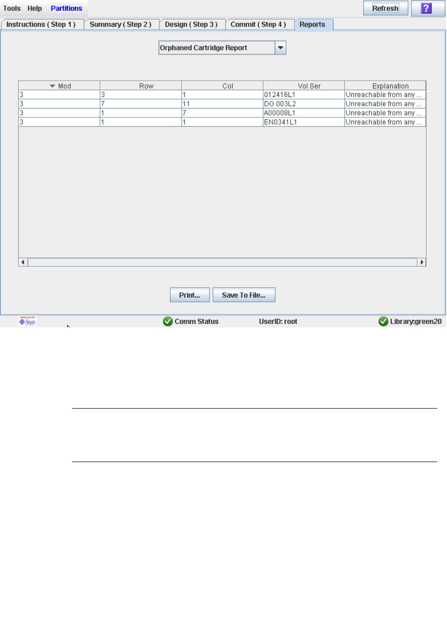
Partition Report Screens
96116 • Revision: KA Chapter 6 Library Partitioning 235
Partitions—Reports—Orphaned Cartridge Report
Sample Screen
Description
Displays the locations and volume serial numbers (VOLIDs) of all orphaned cartridges
in the library. Also identifies why the cartridge is orphaned.
Note – The partition reports display data saved to the library controller database. If
you have made partition configuration changes without commiting the changes to the
library controller through the Commit (Step 4) screen, the data in these reports will
differ from data shown on the partition Summary (Step 2) and Design (Step 3) screens.
You can modify the layout and display of this screen. See “Modifying the Screen
Layout” on page 32 for details.
Optionally, you can print the screen data or save it to a comma-separated file.

Partition Report Screens
236 SL500 User’s Guide • July 2008 Revision: KA • 96116
Screen Fields
Module
Display only.
Module number where the orphaned cartridge is located.
Row
Display only.
Row number where the orphaned cartridge is located. Rows are numbered
consecutively from the top down, with row 1 at the top.
Column
Display only.
Column number where the orphaned cartridge is located. Column location is
referenced from the center of the drive bays. +1 is to the right of the drive bays; -1 is
to the left.
Vol Ser
Display only.
Volume serial number (volid) of the orphaned cartridge.
Explanation
Display only.
Explanation of why the cartridge is orphaned.
Because this report is produced from the library controller database, the only option
is:
■Unreachable from any host
Buttons
Print
Click to print the report on a selected printer.
Save
Click to save the report to a designated comma-separated text file (.csv extension).
Comma-separated files can be opened by a variety of spreadsheet and database
programs.
Refresh
Click to refresh the SL Console partition workspace with current data from the
library controller database. All uncommitted partition changes you have made
during this SL Console login session will be discarded. The Partition Refresh popup
appears, prompting you to confirm the refresh.
? (Help)
Click to display online help for the screen.
See Also
■Partitions—Reports—Cartridge Cell and Media Summary

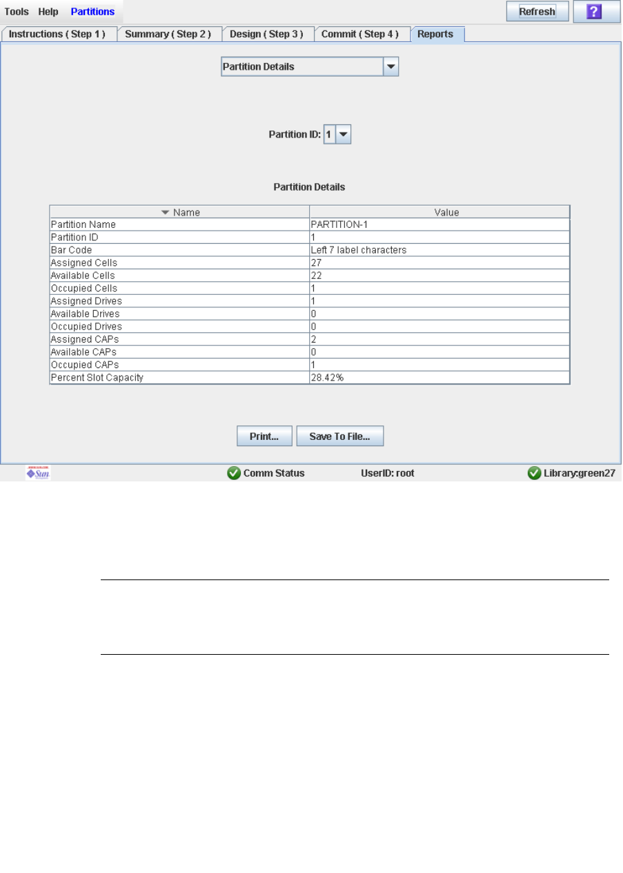
Partition Report Screens
238 SL500 User’s Guide • July 2008 Revision: KA • 96116
Partitions—Reports—Partition Details
Sample Screen
Description
Displays detailed information for a selected partition.
Note – The partition reports display data saved to the library controller database. If
you have made partition configuration changes without commiting the changes to the
library controller through the Commit (Step 4) screen, the data in these reports will
differ from data shown on the partition Summary (Step 2) and Design (Step 3) screens.
You can modify the layout and display of this screen. See “Modifying the Screen
Layout” on page 32 for details.
Optionally, you can print the screen data or save it to a comma-separated file.

Partition Report Screens
96116 • Revision: KA Chapter 6 Library Partitioning 239
Screen Fields
Partition Name
Display only.
Name of the partition.
Partition ID
Display only.
ID of the partition (1–8).
Bar Code
Display only.
Bar code format assigned to the partition.
Assigned Cells
Display only.
Total number of storage cells allocated to the partition.
Available Cells
Display only.
Total number of storage cells in the library available for allocation to the partition.
Occupied Cells
Display only.
Total number of storage cells in the partition with tape cartridges present.
Assigned Drive Bays
Display only.
Total number of drive bays allocated to the partition.
Available Drive Bays
Display only.
Total number of drive bays in the library available for allocation to the partition.
Occupied Drives
Display only.
Total number of installed tape drives in the partition with tape cartridges present.
Assigned CAP cells
Display only.
Total number of CAP cells allocated to the partition.
Available CAP cells
Display only.
Total number of CAP cells in the library available for allocation to the partition. This
number includes all CAP cells in CAPs not allocated to any partition.
This number excludes all CAP cells in CAPs allocated to this partition.
Occupied CAP cells
Display only.

Partition Report Screens
240 SL500 User’s Guide • July 2008 Revision: KA • 96116
Total number of storage cells in the partition with tape cartridges present.
Percent Slot Capacity
Display only.
Percentage of storage cells in the library allocated to this partition. Calculated as:
Number of cells allocated to the partition / Total physical capacity of the library
Buttons
Print
Click to print the report on a selected printer.
Save
Click to save the report to a designated comma-separated text file (.csv extension).
Comma-separated files can be opened by a variety of spreadsheet and database
programs.
Refresh
Click to refresh the SL Console partition workspace with current data from the
library controller database. All uncommitted partition changes you have made
during this SL Console login session will be discarded. The Partition Refresh popup
appears, prompting you to confirm the refresh.
? (Help)
Click to display online help for the screen.
See Also
■Partitions—Reports—Cartridge Cell and Media Summary
■Partitions—Reports—Host Connections Summary
■Partitions—Reports—Orphaned Cartridge Report
■Partitions—Reports—Partition Summary
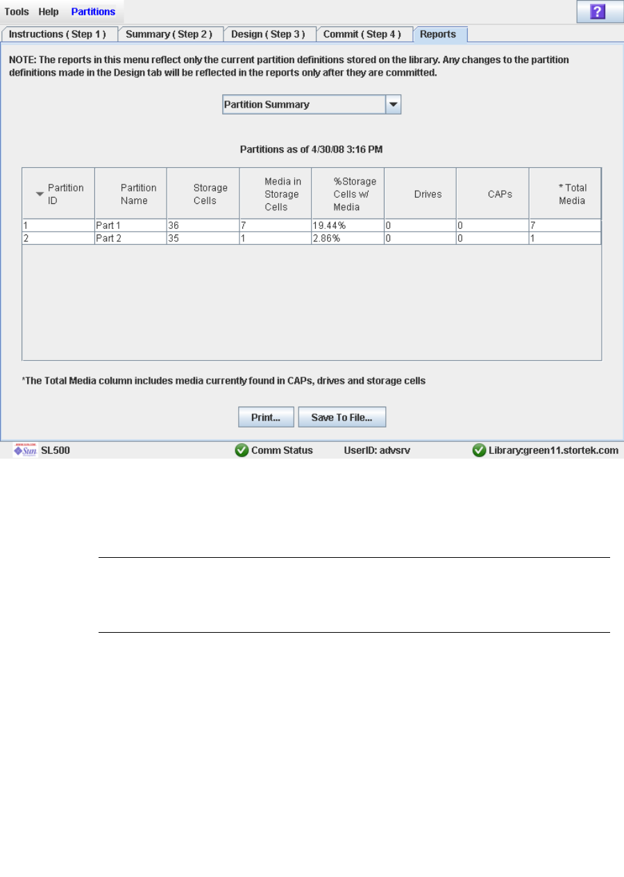
Partition Report Screens
96116 • Revision: KA Chapter 6 Library Partitioning 241
Partitions—Reports—Partition Summary
Sample Screen
Description
Displays summary information for all partitions in the library.
Note – The partition reports display data saved to the library controller database. If
you have made partition configuration changes without commiting the changes to the
library controller through the Commit (Step 4) screen, the data in these reports will
differ from data shown on the partition Summary (Step 2) and Design (Step 3) screens.
You can modify the layout and display of this screen. See “Modifying the Screen
Layout” on page 32 for details.
Optionally, you can print the screen data or save it to a comma-separated file.

Partition Report Screens
242 SL500 User’s Guide • July 2008 Revision: KA • 96116
Screen Fields
Note – These screen fields also appear on the Partitions—Reports—Host Connections
Summary report.
Partition ID
Display only.
ID of the partition (1–8).
Partition Name
Display only.
Name of the partition.
Cell Count
Display only.
Total number of storage cells allocated to the partition.
Drive Count
Display only.
Total number of tape drives allocated to the partition.
CAP Count
Display only.
Total number of CAP cells allocated to the partition.
Cartridge Count
Display only.
Total number of tape cartridges resident in the partition.
% of Cells with Media
Display only.
Percentage of storage cells containing tape cartridges. Calculated as Cartridge Count
/ Cell Count.
Buttons
Print
Click to print the report on a selected printer.
Save
Click to save the report to a designated comma-separated text file (.csv extension).
Comma-separated files can be opened by a variety of spreadsheet and database
programs.
Refresh
Click to refresh the SL Console partition workspace with current data from the
library controller database. All uncommitted partition changes you have made
during this SL Console login session will be discarded. The Partition Refresh popup
appears, prompting you to confirm the refresh.

Partition Report Screens
96116 • Revision: KA Chapter 6 Library Partitioning 243
? (Help)
Click to display online help for the screen.
See Also
■Partitions—Reports—Cartridge Cell and Media Summary
■Partitions—Reports—Host Connections Summary
■Partitions—Reports—Orphaned Cartridge Report
■Partitions—Reports—Partition Details

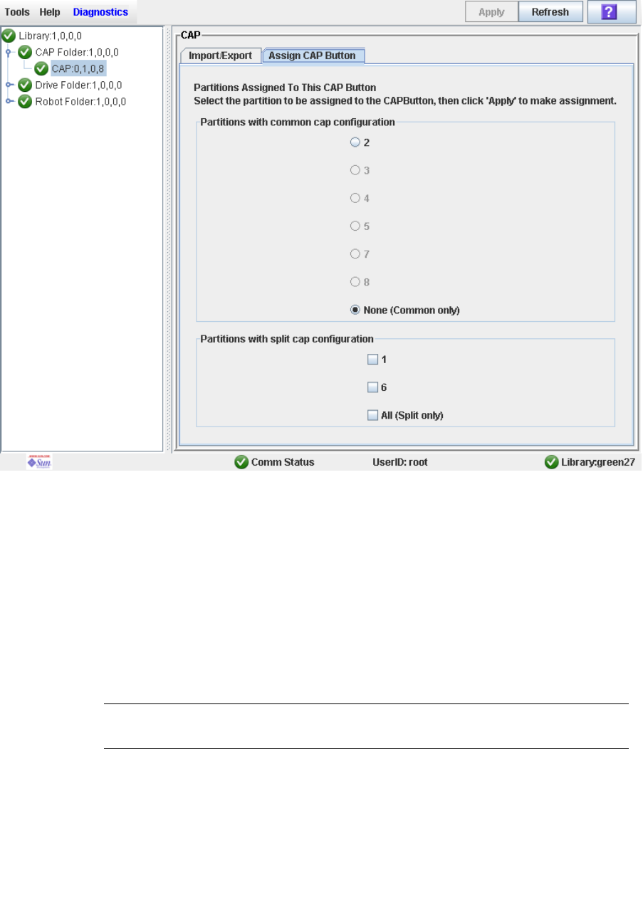
Partition CAP Operation Screens
96116 • Revision: KA Chapter 6 Library Partitioning 245
Diagnostics > CAP—Assign CAP Button
Sample Screen
Description
Allows you to select the partitions to which you want to assign the CAP Open button
on the library control panel. After using this screen, the following actions occur when
you press the CAP Open button:
■The library opens the doors of all CAPs containing cells accessible to the partitions
selected on this screen.
■The library sends CAP status messages to all hosts with access to the exposed cells.
■Doors to CAPs that contain only inaccessible cells do not open.
■Doors to CAPs with cartridges in inaccessible cells do not open.
Note – Depending on how your library’s CAPs are configured, this operation may
expose CAP cells that are not accessible to the requesting host’s partition.

Partition CAP Operation Screens
246 SL500 User’s Guide • July 2008 Revision: KA • 96116
Note – Although it is possible to enter cartridges through a CAP without using the
Assign CAP Button screen, it is recommended that you access the screen first to verify
the partition settings. This will help to prevent cartridges from being entered
inadvertently into the wrong partition.
See “Enter Cartridges Into a Partitioned Library” on page 187 and “Enter Cartridges
Into a Partitioned Library” on page 187 for complete details on using this screen in
conjunction with the CAP Open button.
Screen Fields
Partitions with common CAP configuration
Required.
Partitions with access to common CAP cells are displayed in this table in black type.
Partitions that have not been configured are grayed out.
Select the partition for which you want to enter or eject cartridges. You can select
only one partition at a time from this table. Options are:
■1–8—Click the radio button to select the partition.
■None (Common only)—Click the radio button to de-select all partitions in this
table. This indicates that the enter or eject operation does not involve any
partitions with access to common CAP cells.
Partitions with split CAP configuration
All partitions with access to split CAP cells are displayed in this table.
Select the partitions for which you want to enter or eject cartridges. You can select
more than one partition at a time from this table. Clearing all checkboxes indicates
that the enter or eject operation does not involve any partitions with allocated CAP
cells.
Options are:
■1–8—Click the checkbox to select the partition; clear the checkbox to de-select the
partition.
■All (Split only)—Click the checkbox to select all partitions in this table.
Buttons
Apply
Click to update the library controller database with the current settings from this
screen. The CAP Confirm popup appears, prompting you to confirm the update.
Refresh
Click to refresh the SL Console partition workspace with current data from the
library controller database. All uncommitted partition changes you have made
during this SL Console login session will be discarded. The Partition Refresh popup
appears, prompting you to confirm the refresh.
? (Help)
Click to display online help for the screen.

Partition CAP Operation Screens
96116 • Revision: KA Chapter 6 Library Partitioning 247
See Also
None

Partition CAP Operation Screens
248 SL500 User’s Guide • July 2008 Revision: KA • 96116

96116 • Revision: KA 249
CHAPTER 7
SL Console Diagnostics and Utilities
Library Events
The library controller continually monitors library operations and logs all events.
Events are stored under three headings:
■Communication events—Includes host-to-library, library-to-library, and library-to-
drive communications.
■Error event—Each error event is assigned a four-digit (hexadecimal) action code.
■Warning events—Indicate a loss of performance or conditions that may be indicative
of future, fatal errors.
Event Monitors
You or your Sun support representative can use the SL Console monitors to review
library events. You can spool the event monitor information to a text file.
The following information can help to diagnose the cause of the event:
■Date/time stamp—Identifies when the event occurred.
■Action codes—Identifies the command that was issued, such as “load drive”.
■Result codes—Identifies the result of the requested action.
■Known service plan (KSP) diagnosis—Identifies the mechanism or component
responsible for the task or fault.
Note – There is no option to clear the event log.

Library Self-Tests
250 SL500 User’s Guide • July 2008 Revision: KA • 96116
Library Self-Tests
The self-test diagnostic utility is intended to help diagnose basic problems with the
library. A self-test is typically run after the library is installed. It can be run whenever
necessary.
Note – The library self-test routines are non-disruptive.
Library self-tests involve the following process:
1. Checks the communication path between the library controller, drives, and HandBot.
2. Performs get and put operations to check the health of the HandBot and CAPs. This
includes get and put operations from a reserved cell to a random empty:
■Storage cell
■CAP cell
■Corner cell
3. Performs a full library audit.
4. Performs mounts and dismounts of diagnostic cartridges for all the drives installed
in the library.
Note – The self-test will not start unless a diagnostic cartridge is found in the reserved
cells.
Note – The self-test is repeated for each drive type if a compatible diagnostic cartridge
is found in the reserved cells. If a diagnostic cartridge is not found for a drive type, the
mount/dismount operation is skipped for the drive.

Library Firmware Upgrades
96116 • Revision: KA Chapter 7 SL Console Diagnostics and Utilities 251
Library Firmware Upgrades
Note – This feature is available starting with SL500 firmware version 1022.
The library firmware resides on the library controller. The initial firmware is installed
at the factory. When new firmware is released, you must use the code load utility to
upgrade the firmware on the library and associated devices (CAP and HandBot).
Note – Library firmware does not contain drive code upgrades.
Firmware Download Sites
The SL500 library firmware package is a .img (image) file. See “SunSolve and Helpful
Links” on page xxxi for download sites.
Note – You must have a valid login ID and password for the download site you are
using. Contact your Sun support representative for assistance.
Firmware Installation Process
The process for loading firmware code on the library controller is as follows:
1. Locate the firmware upgrade package (.img file) on the appropriate Sun download
site. See “SunSolve and Helpful Links” on page xxxi.
2. Download the code to a folder on your local PC or workstation.
3. Download the firmware package from your PC to the library controller. This process
also unpacks the package after downloading to make it ready for activation. See
“Download Code to the Library Controller” on page 270.
4. Activate the downloaded code on the library controller. See “Activate Code on the
Library Controller” on page 272.
5. Reboot the library to make the code operational. See “Reboot the Library” on
page 268.

Audits
252 SL500 User’s Guide • July 2008 Revision: KA • 96116
Audits
An audit is the process of reading and cataloging cartridges within a library, verifying
the locations of cartridges, or validating a range of slot locations. The library controller
maintains a cartridge database that contains the following information for all the
cartridges in the library:
■Volume serial numbers (VOLID or VOLSER)
■Current location (in library internal address format)
■Verified status (true or false)
The library audits all cartridge locations in the storage and reserved areas at the
following times:
■An audit request is made through the SL Console.
■A host request to audit the library is entered.
You can use the SL Console to perform the following types of audits:
■Physical Audit
■Verified Audit
Caution – System-level problems may occur if a host’s cartridge record does not match
what is in the library controller cartridge database.
Physical Audit
In a physical audit, the HandBot visits cartridge locations and verifies the VOLID of
resident cartridges, and the library controller updates the cartridge database. This audit
changes the “verified” status of the cartridge locations to “True.” Audit times vary
according to the size of the library.
The library performs a physical audit at the following times.
■When initiated manually from the SL Console. There are two types of manually
initiated physical audits:
■Entire library audit—The HandBot visits all cells (storage, CAP, and drive),
catalogs the VOLIDs and locations, and updates the library controller cartridge
database. This audit is a background process and so does not interrupt online
library operations. See “Audit the Entire Library” on page 275 for details.
Estimated time for such an audit is from less than 10 minutes for a Base Module
to 30 minutes for a maximum size library.
■Specific range audit—The HandBot visits only a specific range of cells (storage,
CAP, and drive) and updates the library controller cartridge database. The audit
information is displayed on the SL Console while the audit is performed. See
“Audit a Range of Cells” on page 277 for details.

Audits
96116 • Revision: KA Chapter 7 SL Console Diagnostics and Utilities 253
Verified Audit
A verified audit validates the status of a specific cartridge location or range of locations
(including CAP and drives) in the cartridge database. If a cartridge address has a
verified status of “false” then a physical audit of that location is performed and the
cartridge database is updated. The progress of the audit is displayed in the Audit
Console section of the SL Console. See “Perform a Verified Audit” on page 279 for
details.

Robot Diagnostic Moves
254 SL500 User’s Guide • July 2008 Revision: KA • 96116
Robot Diagnostic Moves
Note – This feature is available starting with SL500 firmware version 1026 and
SL Console version 2.40.
Diagnostic moves are used to monitor or diagnose a problem with a HandBot. The
move can be performed with or without cartridges.
Successful diagnostic moves do not rearrange the cartridges in the storage cells;
cartridges are returned to their original locations after the diagnostic move is
completed. However, some diagnostic move failures can cause cartridges to be left in
new locations.
A diagnostic move involves the following elements:
■Target Address Range
■Pool Address Range
■Move Access Order
Target Address Range
The target address range defines the location parameters in a library within which the
get operation is performed in a diagnostic move. There are two types of access orders
for a target address:
■“Sequential Access Order” on page 255
■“Random Access Order” on page 255
Following are valid target address types:
■Storage cells—Reserves all the storage locations as the target range
■CAP—Reserves the cells in the as the target/pool range.
■Drive and Storage cells—Reserves all the drives and storage cells as the target/pool
range.
■System cells—Reserves the locations (reserved cells) containing the cleaning or
diagnostic cartridges as the target/pool range.
■All—Reserves all storage cells, CAP and Drives as target/pool range.
Note – Selecting the Storage, CAP, drive, system, or All option does reserve all the
associated locations as the target range. However, only the location currently being
accessed by the HandBot for a get/put operation is unavailable to the host.
Robot Diagnostic Moves
96116 • Revision: KA Chapter 7 SL Console Diagnostics and Utilities 255
Pool Address Range
The pool address range locations are used to supply cartridges required for diagnostic
moves to and from the target address range. A pool address is also used in a get
operation if a target address does not contain a cartridge. There is no specified access
order within the pool address range. The pool address ranges does not include drive
locations.
Note – The address ranges are in the Library, Module, Row, and Column format.
Note – The pool address ranges cannot contain drive locations.
Move Access Order
Sequential Access Order
In a sequential access order diagnostic move, the HandBot performs a get operation
starting with the first location in the target address ranges and then continues visiting
the locations sequentially through the range until it completes the requested number of
moves.
Note – If you choose not to move cartridges the get/put operations are not performed.
The HandBot just positions itself at the target and pool addresses.
Random Access Order
In a random access order diagnostic move, the HandBot randomly picks a location in
the target address range to get a cartridge. The HandBot can also visit the same location
in the in the target address range multiple times to get a cartridge. The random access
routine ends after the requested number of moves is complete.
If you choose not to move cartridges the get/put operations are not performed. The
HandBot just positions itself at the target and pool addresses.

Robot Diagnostic Moves
256 SL500 User’s Guide • July 2008 Revision: KA • 96116
Diagnostic Move Control Functions
The following options are available to manage the moves currently open:
Note – If multiple diagnostic moves are open, then each move has its own monitor
screen.
To Select Menu Option Notes
Start File > Start Sequence
Pause File > Pause Sequence Stops all diagnostic moves, but
maintains the current location in the
access order.
Stop File > Stop Sequence Stops a running or paused exerciser.
Resume File > Start Sequence Resumes a paused exerciser starting
with the last known location in the
target address range.
Clear the messages
displayed in the monitor
window
File > Clear Output Window Erases the previous message lines and
continues to fill the screen with new
messages.
Spool Spool File > Start Spooling Directs the move output to a file.
Stop spooling the exerciser
output to a file
Spool File > Stop Spooling Stops directing the move output to the
spool file.
Troubleshooting
96116 • Revision: KA Chapter 7 SL Console Diagnostics and Utilities 257
Troubleshooting
Before you run diagnostic tests, check the following areas of the library using the
troubleshooting tips in the following table:
TABLE 7-1 Troubleshooting Table
Problem What to do
Service Required
(amber) LED is
constantly on.
Perform the following procedure:
Using the SL Console, check the health of the library and the attached
devices (drives, CAP, and robots). See “StorageTek Library Console”
on page 27 for more details about operations.
To perform a health check:
1. Log in to the SL Console application.
2. Access the System Detail module, View > System Detail.
3. Check the device tree for the following indicators:
■Device Healthy
■Device Error
The Status (for example, online/offline) and Statistics (for example,
uptime, downtime, errors and warnings) tabs provide more
information on the health of the library and devices.
Other checks:
■Make sure that cartridges are fully seated and properly oriented in their
storage cells.
■Inspect the X table for any foreign objects or debris; remove them if found.
Library does not power-
on. The SL Console
does not display any
messages.
1. Check that the library power switch is in the ON position.
2. Check all power cord connections.
3. Replace the power cord.
4. Make sure that there is power to the outlet.
CAP open LED is on
and blinking.
Open the CAP and make sure that the cartridges in the CAP cells are
properly seated.
The client computer
cannot communicate
with the library or tape
drives.
Make sure that cables are securely attached to their connectors on the
rear of the library, tape drives, and client computer.
The SL Console does
not display modified
data or information
remains static.
Check the SL Console Heartbeat icon.
Troubleshooting
258 SL500 User’s Guide • July 2008 Revision: KA • 96116
Robot Fault or Library
Fault Amber LED is
constantly on.
1. Check the SL Console for any displayed error messages. Write down
the error messages reported.
2. Open the front door. Observe and note the state of the cartridges,
hand, and tape drives.
3. .Make sure that cartridges are fully seated and properly oriented in
their storage cells.
4. Make sure that packing materials have been removed.
5. Inspect the library floor for any objects or debris; remove them.
6. Check the status of the tape drives.
7. Close the front door.
8. Make sure that the tape drives are fully seated and locked forward
by pushing and pulling on the rear of the drive tray. Any motion of
the tray indicates that it requires reseating and locking down.
Tape drive is unable to
eject a cartridge.
Manually remove the cartridge from the tape drive. “Remove a
Cartridge from a Tape Drive” on page 325.
The client computer
cannot communicate
with the library or tape
drives.
1. Make sure that cables are securely attached to their connectors on
the rear of the library, the tape drives, and the client computer.
2. Make sure that each SCSI device a same bus has a unique address
and that the last device is properly terminated.
The library is unable to
communicate with the
drives.
Drive status on the
SL Console displays
Not communicating.
1. Make sure that cables are securely attached to their connectors on
the rear of the library, the drives, and the client computer.
2. Make sure that each SCSI device on a bus has a unique address and
that the last device is properly terminated.
Repeated or excessive
drive cleanings or
cleaning messages.
1. Replace the cleaning cartridge with a new cleaning cartridge.
2. Run the Library Self-Test and note if errors are reported for the
drive.
3. Run any client computer-based drive diagnostic tests.
Cartridge stuck in tape
drive.
See “Remove a Cartridge from a Tape Drive” on page 325.
Tape drive is unable to
eject a cartridge.
See “Remove a Cartridge from a Tape Drive” on page 325.
TABLE 7-1 Troubleshooting Table (Continued)
Problem What to do

Diagnostic and Utility Tasks
96116 • Revision: KA Chapter 7 SL Console Diagnostics and Utilities 259
Diagnostic and Utility Tasks
Library diagnostic and utility tasks are divided into the following categories:
■“Event Monitor Tasks” on page 260
■“Library Utility Tasks” on page 266
■“Audit Tasks” on page 274
■“Drive Utility Tasks” on page 281
■“HandBot Utility Tasks” on page 285


Event Monitor Tasks
96116 • Revision: KA Chapter 7 SL Console Diagnostics and Utilities 261
▼ Display an Event Monitor
Event monitor information is dynamically updated depending upon occurrence of the
selected events. The information sent during an e-mail, print, save, or spool operation
reflects the data (and format) shown on-screen at the time the operation is requested.
Note – Event monitors are useful tools for root cause analysis of errors. If the library is
experiencing reproducible errors, you can open an event monitor and spool all events
to a file to capture the data. Later, you can send the file to your Sun support
representative for analysis.
Note – To monitor multiple events, see “Display Multiple Monitors” on page 265.
1. Select Tools > Monitors.
2. Expand the Permanent Monitors folder.
The library monitors you have access to are displayed.
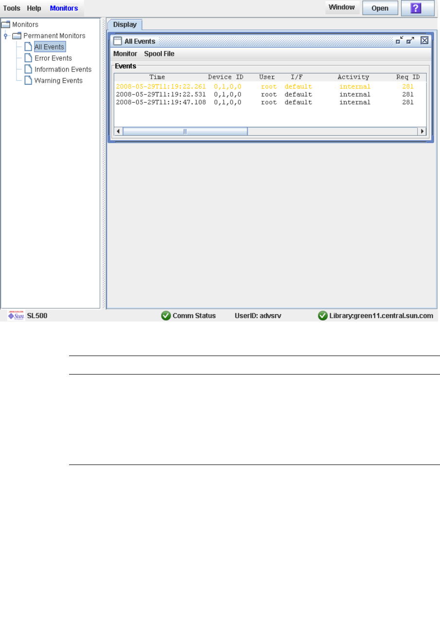
Event Monitor Tasks
262 SL500 User’s Guide • July 2008 Revision: KA • 96116
3. Click the event monitor you want to use, and then click Open from the Options Bar.
The system displays the associated data collected for the event.
4. Use these options to manage the information displayed on the screen for the event
selected:
5. To close a monitor, click the X in the upper right corner of the window.
Select To
Monitor > Pause Pause the continuous display of data related to the event
selected
Monitor > Resume Resume displaying the events
Monitor > Stop Permanently stop the continuous display of data related to the
event selected
Monitor > Clear Clear the event monitor display
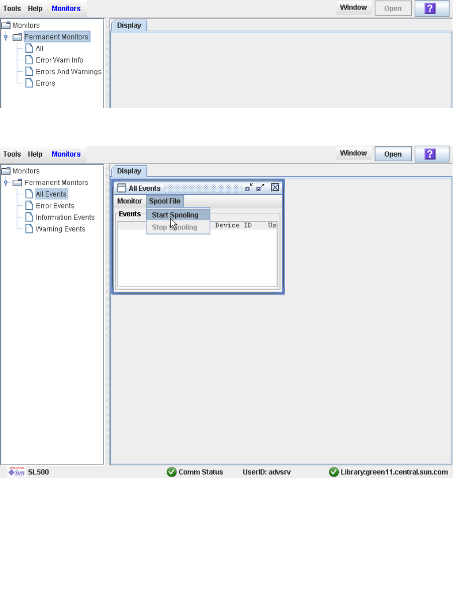
Event Monitor Tasks
96116 • Revision: KA Chapter 7 SL Console Diagnostics and Utilities 263
▼ Spool Event Monitor Data to a File
Use this procedure to spool and save event monitor data to a file. You can send the file
to your Sun support representative to assist in diagnosing problems.
1. Select Tools > Monitors.
2. Expand the Permanent Monitors folder.
The library monitors you have access to are displayed.
3. Click the event monitor you want to use, and then click Open from the Options Bar.
The system displays the an event monitor window.
4. In the event monitor window, select Spool File > Start Spooling.
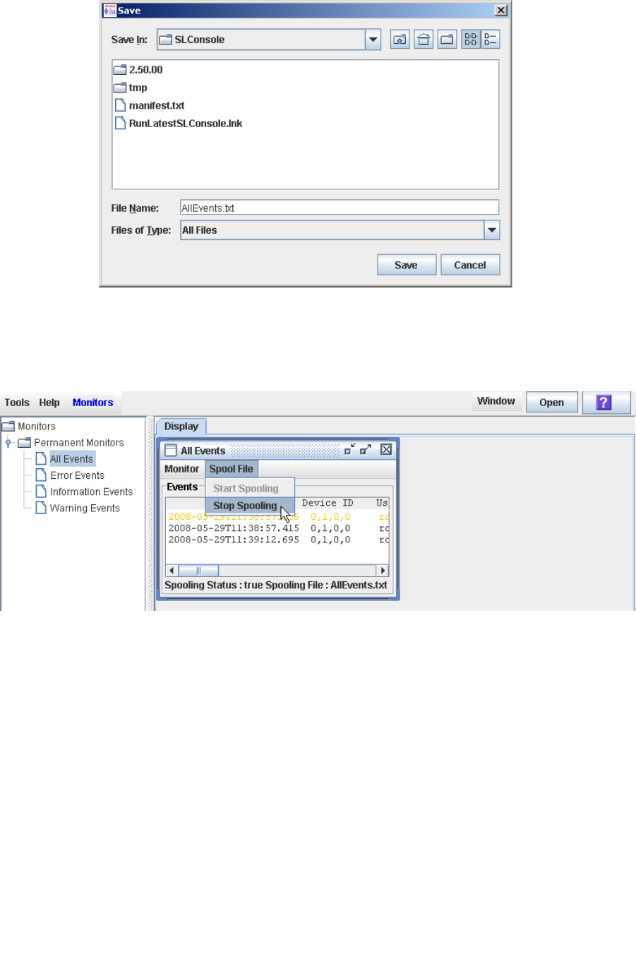
Event Monitor Tasks
264 SL500 User’s Guide • July 2008 Revision: KA • 96116
The Save popup appears.
5. Browse to the directory where you want to save the file. In the File Name field, enter
the file name, and click Save.
All event data is spooled to the specified file.
6. To stop spooling, select Monitor > Stop Spooling.
Following is a sample of the spool file:
2008-05-29T11:23:27.448 0,1,0,0 root default internal 281 warn
0 rb_Reboot::reboot(): Resetting drive [0,3,4,9]
2008-05-29T11:23:27.760 0,1,0,0 root default internal 281 info
0 Service Beacon is ACTIVE: Current Health Event indicates Drive 04 in Module 03 is
not operational
2008-05-29T11:23:53.211 0,1,0,0 root default internal 281 info
0 Service Beacon is ACTIVE: Current Health Event indicates Drive 04 in Module 03 is
operational

Event Monitor Tasks
96116 • Revision: KA Chapter 7 SL Console Diagnostics and Utilities 265
▼ Display Multiple Monitors
You can open and manage multiple event monitors using these selections from the
Options Bar:
To Select
Custom arrange the open monitors on screen Window >
Arrange
Arrange the event monitor windows horizontally Window > Tile
Horizontal
Arrange the event monitor windows vertically Window > Tile
Vertical
Stack the event monitors Window >
Cascade

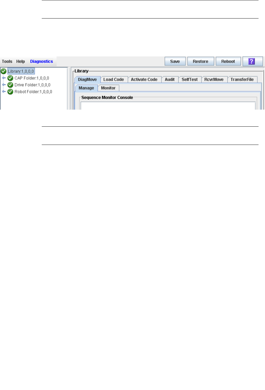
Library Utility Tasks
96116 • Revision: KA Chapter 7 SL Console Diagnostics and Utilities 267
▼ Perform a Library Self-Test
Note – The proper diagnostic cartridges for library drives must be present in the
library.
1. Select Tools > Diagnostics.
2. Click the Library folder on the device tree.
The Library screen appears.
3. Click the SelfTest tab.
Note – The self-test screen displays a Mode field with two options: disruptive and non-
disruptive. At present, only the non-disruptive option is valid.
4. Click the Run tab from the Options Bar.
During the self-test the SL Console window displays the status of the various
diagnostics being performed.
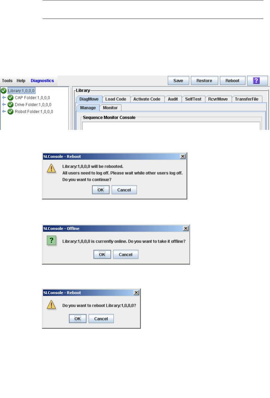
Library Utility Tasks
268 SL500 User’s Guide • July 2008 Revision: KA • 96116
▼ Reboot the Library
Note – This feature is available starting with SL500 firmware version 1026 and
SL Console version 2.40.
Use this procedure to reboot the library. This process involves reloading the firmware
from flash memory and restarting the library controller.
1. Select Tools > Diagnostics.
2. Click the Library folder on the device tree.
The Library screen appears.
3. Click Reboot in the Options Bar.
The Reboot confirmation popup appears.
4. Click OK to continue.
If the library is online, the Offline confirmation popup appears.
5. Click OK to vary the library offline.
The Reboot confirmation popup appears
6. Click OK to continue.
The SL Console termination popup appears.

Library Utility Tasks
96116 • Revision: KA Chapter 7 SL Console Diagnostics and Utilities 269
7. Click OK to terminate this SL Console session.
You are logged off the SL Console.
The library controller reboots the library. This may take several minutes.
Note – You will not be able to log back in to the SL Console until the library has fully
initialized.
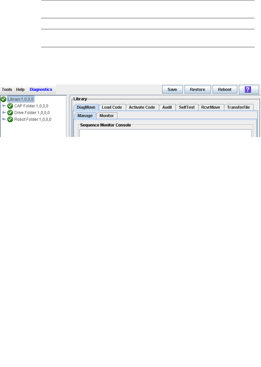
Library Utility Tasks
270 SL500 User’s Guide • July 2008 Revision: KA • 96116
▼ Download Code to the Library Controller
Use this procedure to download updates to the library controller firmware. This
procedure is not used for downloading drive firmware updates.
Note – You can perform this procedure only from the standalone SL Console or Web-
launched SL Console, not the local operator panel.
Note – This feature is available starting with SL500 firmware version 1026 and
SL Console version 2.40.
1. Select Tools > Diagnostics.
2. Click the Library folder on the device tree.
The Library screen appears.
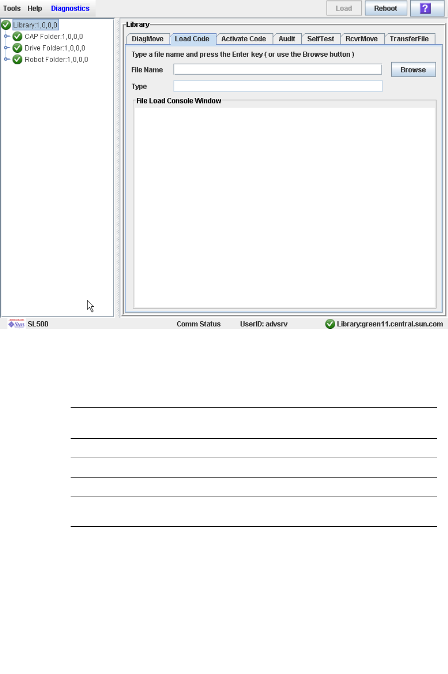
Library Utility Tasks
96116 • Revision: KA Chapter 7 SL Console Diagnostics and Utilities 271
3. Click the Load Code tab.
4. Click the Browse button to locate, select the folder and file name containing the
firmware package (.img file) on your PC, and then click Open.
5. Click the Load button from the Options Bar.
6. Click OK to confirm the download.
Note – The download process could take up to five minutes. The SL Console indicates
the progress of the file transfer from the PC to the library controller.
Note – After the downloading, the system unpacks the package.
Note – You can store up to two versions of the SL500 code. If you exceed this limit, a
delete button pops up prompting you to delete a code version.
7. After the package is successfully unpacked, you can activate the code immediately,
or you can wait until a later time. See “Activate Code on the Library Controller” on
page 272 for detailed instructions.
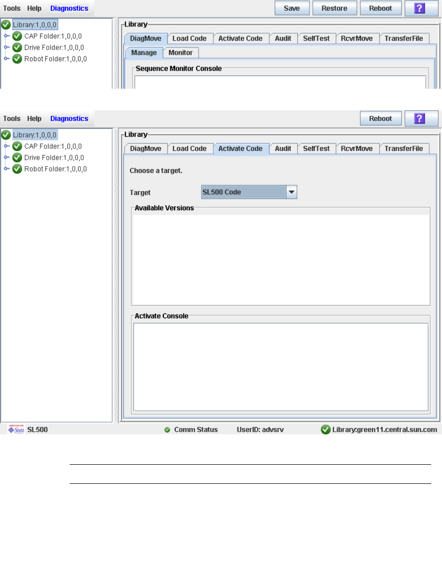
Library Utility Tasks
272 SL500 User’s Guide • July 2008 Revision: KA • 96116
▼ Activate Code on the Library Controller
Activating the code makes the code residing in the library controller ready for
operation.
1. Select Tools > Diagnostics,
2. Click the Library folder on the device tree.
The Library screen appears.
3. Click the Activate Code tab.
4. Click the Target on the pull-down menu.
Note – Target refers to firmware package (.img file) containing the SL500 library code.
5. Click the code to activate from the Available Versions section.

Library Utility Tasks
96116 • Revision: KA Chapter 7 SL Console Diagnostics and Utilities 273
Note – The version prefixed with an “*” is the code currently active. You can not select
this code again to activate.
6. Click the Activate button in the Options Bar.
Note – The activate code process could take up to ten minutes to complete.
Caution – POTENTIAL INTERNAL FILE CORRUPTION. Do not reboot any devices in
the library or execute any operations on the library while code is being activated.
7. Click OK to continue.
Note – The Activate Console screen displays the status of the code activation process.
The code you just activated is listed in the available versions section, marked with an
“*”. The unpacked version and previously activated versions of the code are also listed
(without the “*”).
8. The system prompts you to reboot the library. Click OK to reboot the library.
Note – The library has two versions of the image file residing in the flash memory.
After the library completes the reboot process, the latest image becomes active and the
earlier version serves as a backup. The earlier version may be restored if required.
9. Click OK to terminate the SL Console session.
10.In the logon screen, click Exit to close the application.

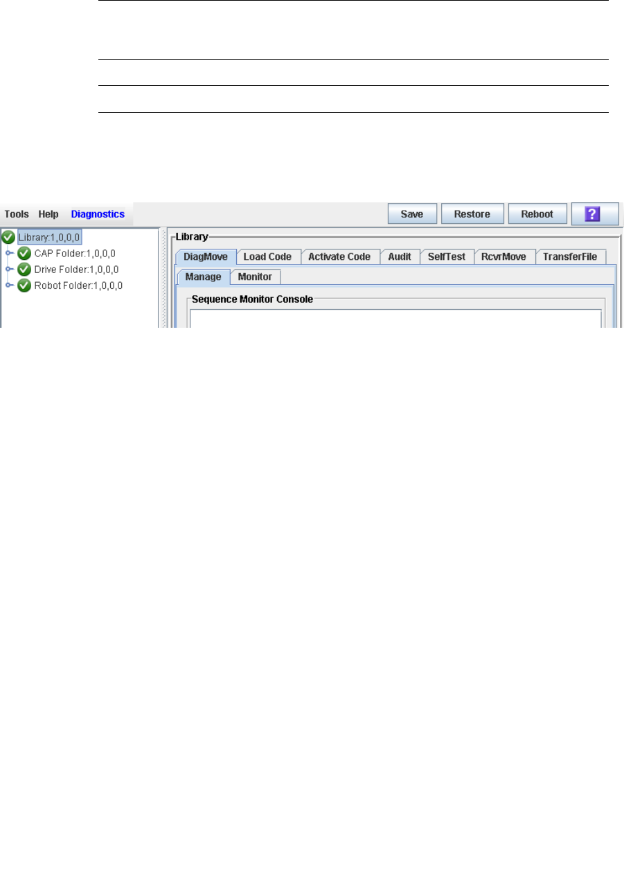
Audit Tasks
96116 • Revision: KA Chapter 7 SL Console Diagnostics and Utilities 275
▼ Audit the Entire Library
During this audit the HandBot visits all the storage cells, catalogs the VOLIDs and
locations, and updates the library controller database.
Note – Although this audit is a background process and does not interrupt library
operations, it does require sharing of HandBot resources. Therefore, it is not
recommended that you run this audit during peak activity periods.
Note – You cannot stop this audit once it has initiated.
1. Select Tools > Diagnostics.
2. Click the Library folder on the device tree.
The Library screen appears.
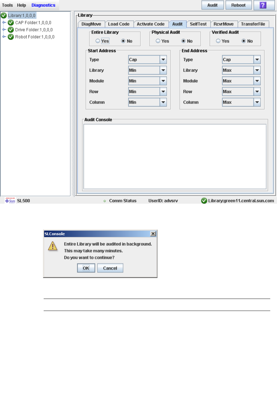
Audit Tasks
276 SL500 User’s Guide • July 2008 Revision: KA • 96116
3. Click the Audit tab.
The Library Audit screen appears.
4. In the Entire Library field, click Yes. Then click the Audit button in the Options Bar.
A confirmation popup appears.
5. Click OK to perform the audit as a background process or Cancel to cancel the audit.
Note – Once you click OK, you cannot stop the audit; it will run until completion.
6. You can view the Cartridge Summary report after a few hours for the latest cartridge
locations and VOLIDs. See “Display a Library Report” on page 74 for details.
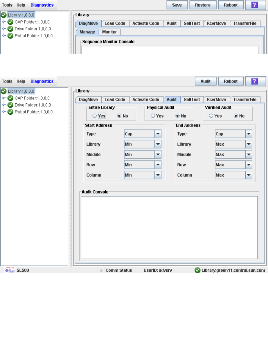
Audit Tasks
96116 • Revision: KA Chapter 7 SL Console Diagnostics and Utilities 277
▼ Audit a Range of Cells
During this audit the HandBot visits only a specific range of storage cells (including the
cap and drives) and updates the library controller database.
1. Select Tools > Diagnostics.
2. Click the Library folder on the device tree.
The Library screen appears.
3. Click the Audit tab.
The Library Audit screen appears.
4. In the Entire Library field, click No. In the Physical Audit field, click Yes. In the
Verified Audit field, click No.
5. In the Start Address and End Address fields, select the device types you want to
audit and the starting and ending library internal address locations.
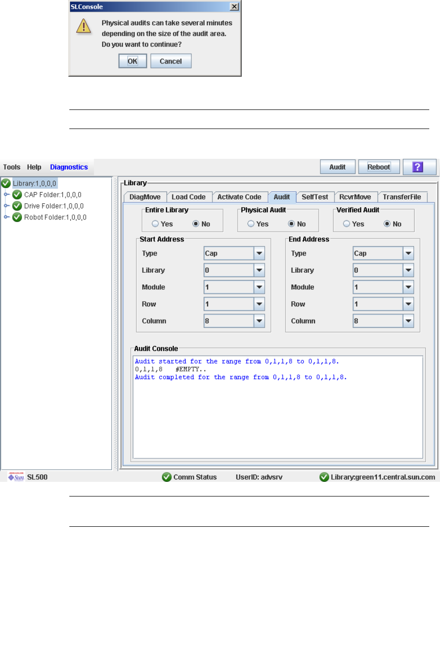
Audit Tasks
278 SL500 User’s Guide • July 2008 Revision: KA • 96116
6. Click the Audit button in the Options Bar.
A confirmation popup appears.
7. Click OK to perform the audit as a background process or Cancel to cancel the audit.
Note – Once you click OK, you cannot stop the audit; it will run until completion.
8. The Audit Console section displays the progress of the audit.
Note – You can also view the Cartridge Summary report for the latest cartridge
locations and VOLIDs. See “Display a Library Report” on page 74 for details.
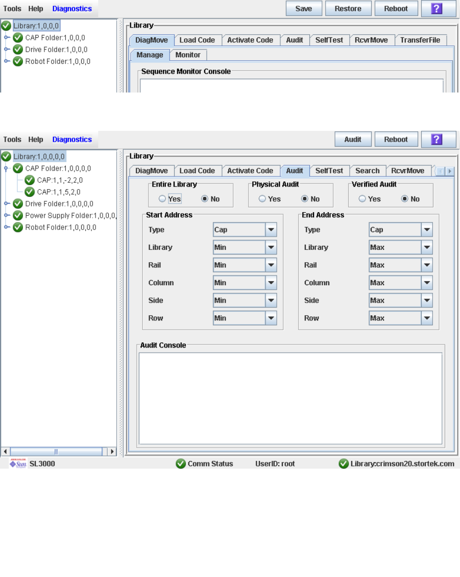
Audit Tasks
96116 • Revision: KA Chapter 7 SL Console Diagnostics and Utilities 279
▼ Perform a Verified Audit
A verified audit validates the status of a specific cartridge location or a range of
locations (including CAP and drives) in the library controller database. If a cartridge
address has a verified status of “false” then a physical audit of that location is
performed and the library controller database is updated.
1. Select Tools > Diagnostics.
2. Click the Library folder on the device tree.
The Library screen appears.
3. Click the Audit tab.
The Library Audit screen appears.
4. In the Entire Library field, click No. In the Physical Audit field, click No. In the
Verified Audit field, click Yes.
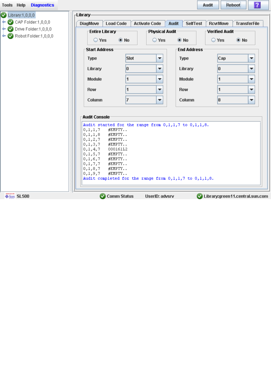
Audit Tasks
280 SL500 User’s Guide • July 2008 Revision: KA • 96116
5. In the Start Address and End Address fields, select the device types you want to
audit and the starting and ending library internal address locations.
6. Click the Audit button in the Options Bar.
The Audit Console section displays the progress of the audit.

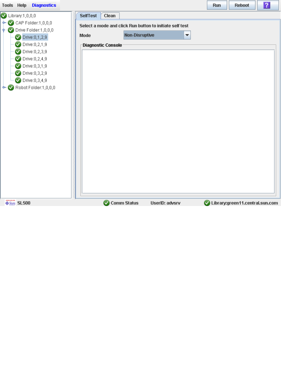
Drive Utility Tasks
282 SL500 User’s Guide • July 2008 Revision: KA • 96116
▼ Perform a Drive Self-Test
1. Select Tools > Diagnostics.
2. Expand the Drive Folder, and click the drive you want to test.
3. Click the SelfTest tab.
4. In the Mode pull-down, click Non-Disruptive.
5. Click the Run button from the Options Bar.
Status messages are displayed as the self-test is run. A Diagnostic completed message
appears when the test finishes.
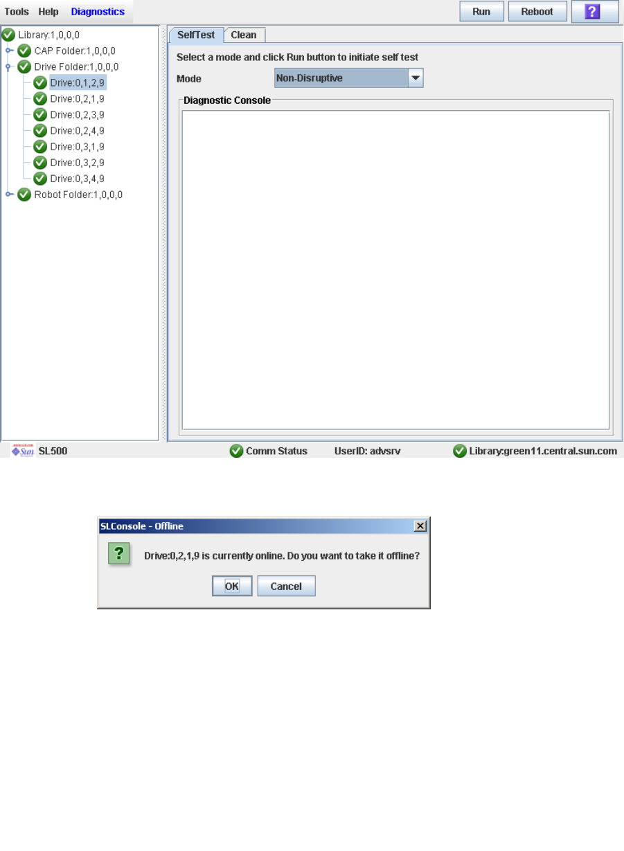
Drive Utility Tasks
96116 • Revision: KA Chapter 7 SL Console Diagnostics and Utilities 283
▼ Reboot a Drive
Use this procedure to reboot a drive.
1. Select Tools > Diagnostics.
2. Expand the Drive Folder, and click the drive you want to modify.
3. Click Reboot in the Options Bar.
If the drive is offline, the Offline Confirm popup appears.
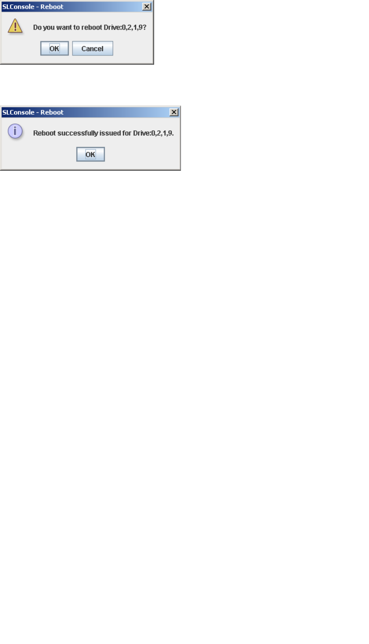
Drive Utility Tasks
284 SL500 User’s Guide • July 2008 Revision: KA • 96116
4. Click OK to vary the drive offline.
The Reboot Confirm popup appears.
5. Click OK.
The library controller reboots the drive, and the Reboot Success popup appears.
6. Click OK to dismiss the popup.

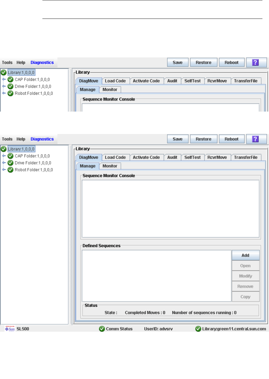
HandBot Utility Tasks
286 SL500 User’s Guide • July 2008 Revision: KA • 96116
▼ Define a Diagnostic Move
Multiple diagnostic move routines can be set up and run simultaneously, as long as the
target and pool address ranges do not overlap.
Note – This procedure requires sharing of HandBot resources; therefore, it is not
recommended that you run it during peak activity periods.
1. Select Tools > Diagnostics.
2. Click the Library folder on the device tree.
The Library screen appears.
3. Click the DiagMove tab and then the Manage tab.
The Diagnostic Move Manage screen appears.
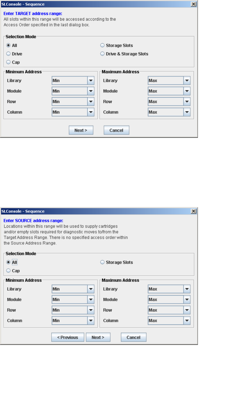
HandBot Utility Tasks
96116 • Revision: KA Chapter 7 SL Console Diagnostics and Utilities 287
4. In the Defined Sequence section, click Add.
The TARGET screen appears.
5. Complete the TARGET screen as follows. See “Target Address Range” on page 254
for details.
■In the Selection Mode field, click the type of cells you want to diagnose.
■In the Minimum Address and Maximum Address fields, select the library internal
address of the starting and ending locations of the cells you want to diagnose.
6. Click Next.
The SOURCE screen appears.
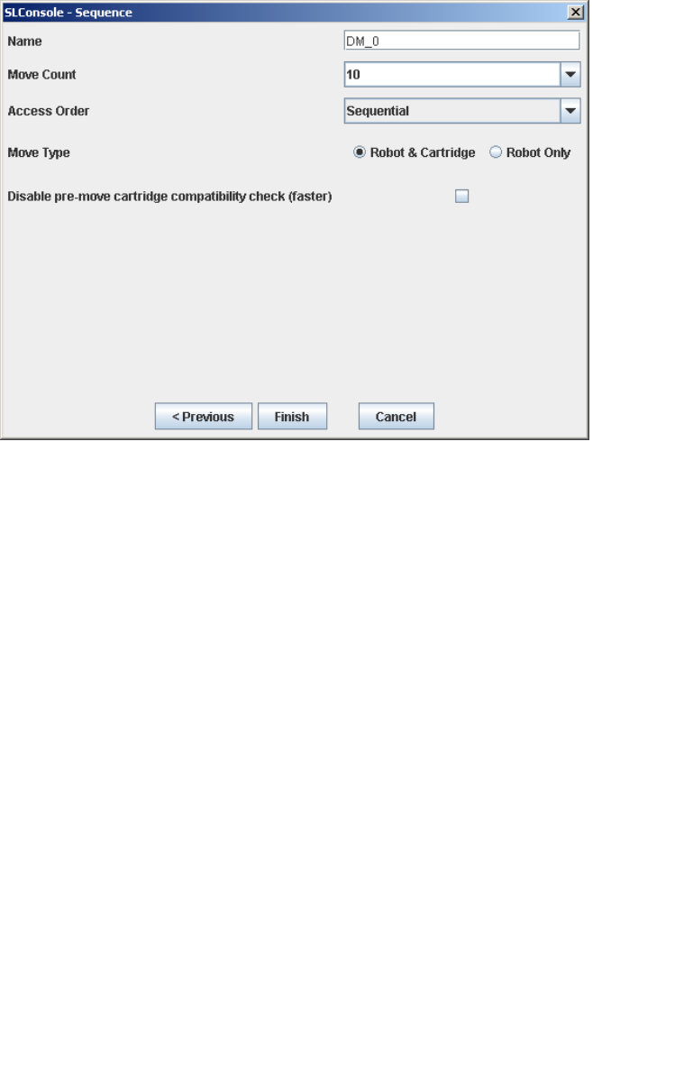
HandBot Utility Tasks
288 SL500 User’s Guide • July 2008 Revision: KA • 96116
7. Complete the SOURCE screen as follows. See “Pool Address Range” on page 255 for
details.
■In the Selection Mode field, click the appropriate cartridge pool address type.
■In the Minimum Address and Maximum Address fields, select the library internal
addresses of the starting and ending locations of the cartridge pool you want to use.
8. Click Next.
The Sequence screen appears.
9. Complete the Sequence screen as follows. See “Move Access Order” on page 255 for
details.
■Name of the diagnostic move
■Move Count (specify a number between 1 and 5000)
■Access order (Sequential or Random)
■Move Type (Robot and Cartridge or Robot Only)
■Disable pre move cartridge compatibility check
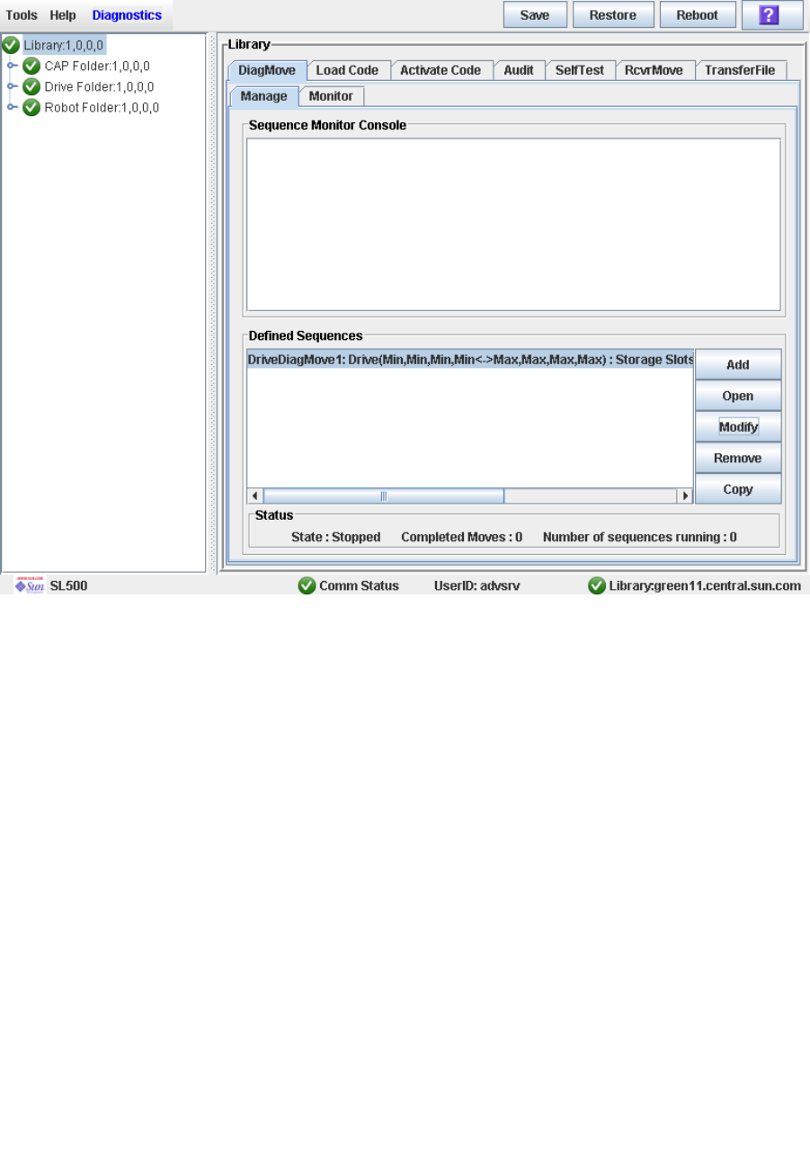
HandBot Utility Tasks
96116 • Revision: KA Chapter 7 SL Console Diagnostics and Utilities 289
10.Click Finish to complete the setup.
The Diagnostic Move Manage screen appears. The diagnostic sequence you have just
defined is listed in the Defined Sequences section.
HandBot Utility Tasks
290 SL500 User’s Guide • July 2008 Revision: KA • 96116
▼ Manage Diagnostic Move Definitions
Use this procedure to manage diagnostic move sequence definitions.
1. Select Tools > Diagnostics.
2. Click the Library folder on the device tree.
The Library screen appears.
3. Click the DiagMove tab and then the Manage tab.
The Diagnostic Move Manage screen appears.

HandBot Utility Tasks
96116 • Revision: KA Chapter 7 SL Console Diagnostics and Utilities 291
4. From the Defined Sequences section, select any of the following options:
5. To manage the diagnostic moves currently open, see “Monitor and Control Open
Diagnostic Moves” on page 296.
Select
Option To Notes
Add Define a diagnostic move
Open Start a diagnostic move Multiple diagnostic moves may be open at a time, so long as
the target and pool address ranges setup for the moves do
not overlap.
Modify Modify options for a
diagnostic move
This diagnostic move routine must not be open or if open
must be in a “Stopped” state.
Remove Remove a diagnostic move This diagnostic move routine must not be open.
Copy Copy an existing diagnostic
move
Copy a diagnostic move definition, make changes if
necessary, and assign a different name.
HandBot Utility Tasks
292 SL500 User’s Guide • July 2008 Revision: KA • 96116
▼ Save a Diagnostic Move to a File
Use this procedure to save a defined diagnostic move to a local file on your workstation
or PC. The file is saved as a JavaBean component represented as an XML 1.0 document
(.xml).
Possible uses for the saved file are:
■Can be used to restore a move that has been deleted from the library.
■Can be copied to a different library for use there.
1. Select Tools > Diagnostics.
2. Click the Library folder on the device tree.
The Library screen appears.
3. Click the DiagMove tab and then the Manage tab.
The Diagnostic Move Manage screen appears.
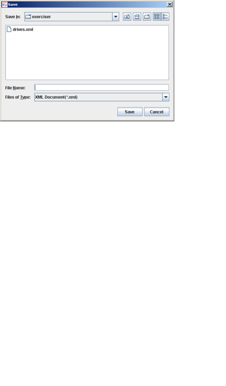
HandBot Utility Tasks
96116 • Revision: KA Chapter 7 SL Console Diagnostics and Utilities 293
4. Click the diagnostic move you want to save, and then click the Save button in the
Options Bar.
The Save popup appears.
5. Browse to the directory where you want to save the file. In the File Name field, enter
the file name.
6. Click Save.
The data is saved to the specified file. Following is a sample excerpt:
<?xml version="1.0" encoding="UTF-8"?>
<java version="1.5.0_11" class="java.beans.XMLDecoder">
<object class="com.stortek.ats.elib.opel.model.SequenceBeanList">
<string>FRS_4.10</string>
<string>SL500</string>
<void method="add">
<object class=
"com.stortek.ats.elib.opel.model.SequenceBeanList$SequenceBean">
<void property="accessOrder">
<string>Sequential</string>
</void>
<void property="moveCartridge">
<boolean>true</boolean>
</void>
<void property="moveCount">
<int>10</int>
</void>
<void property="name">
<string>DriveDiagMove1</string>
</void>
...
<void property="targetType">
<string>Drive</string>
</void>
</object>
</void>
</object>
</java>
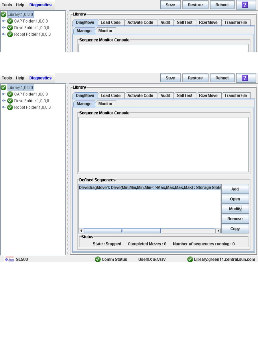
HandBot Utility Tasks
294 SL500 User’s Guide • July 2008 Revision: KA • 96116
▼ Start a Diagnostic Move
1. Select Tools > Diagnostics.
2. Click the Library folder on the device tree.
The Library screen appears.
3. Click the DiagMove tab and then the Manage tab.
The Diagnostic Move Manage screen appears.
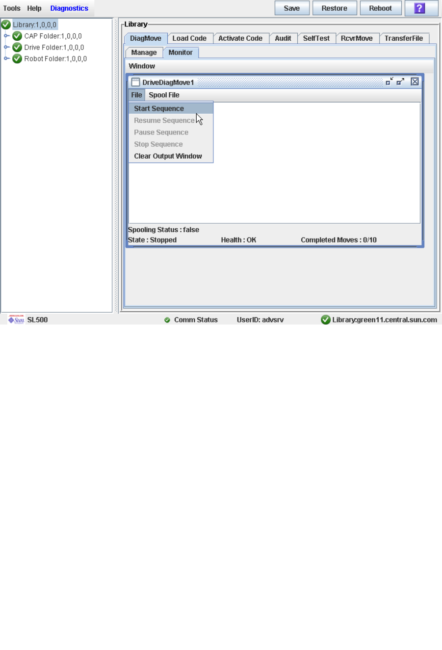
HandBot Utility Tasks
96116 • Revision: KA Chapter 7 SL Console Diagnostics and Utilities 295
4. From the Defined Sequences section click a diagnostic move and then click Open.
The Monitor window is activated.
You can repeat this step to open multiple moves, as long as the target and pool address
ranges for the moves do not overlap.
A monitor window is displayed for each move you open.
5. From each monitor window, select File > Start Sequence to start the move.
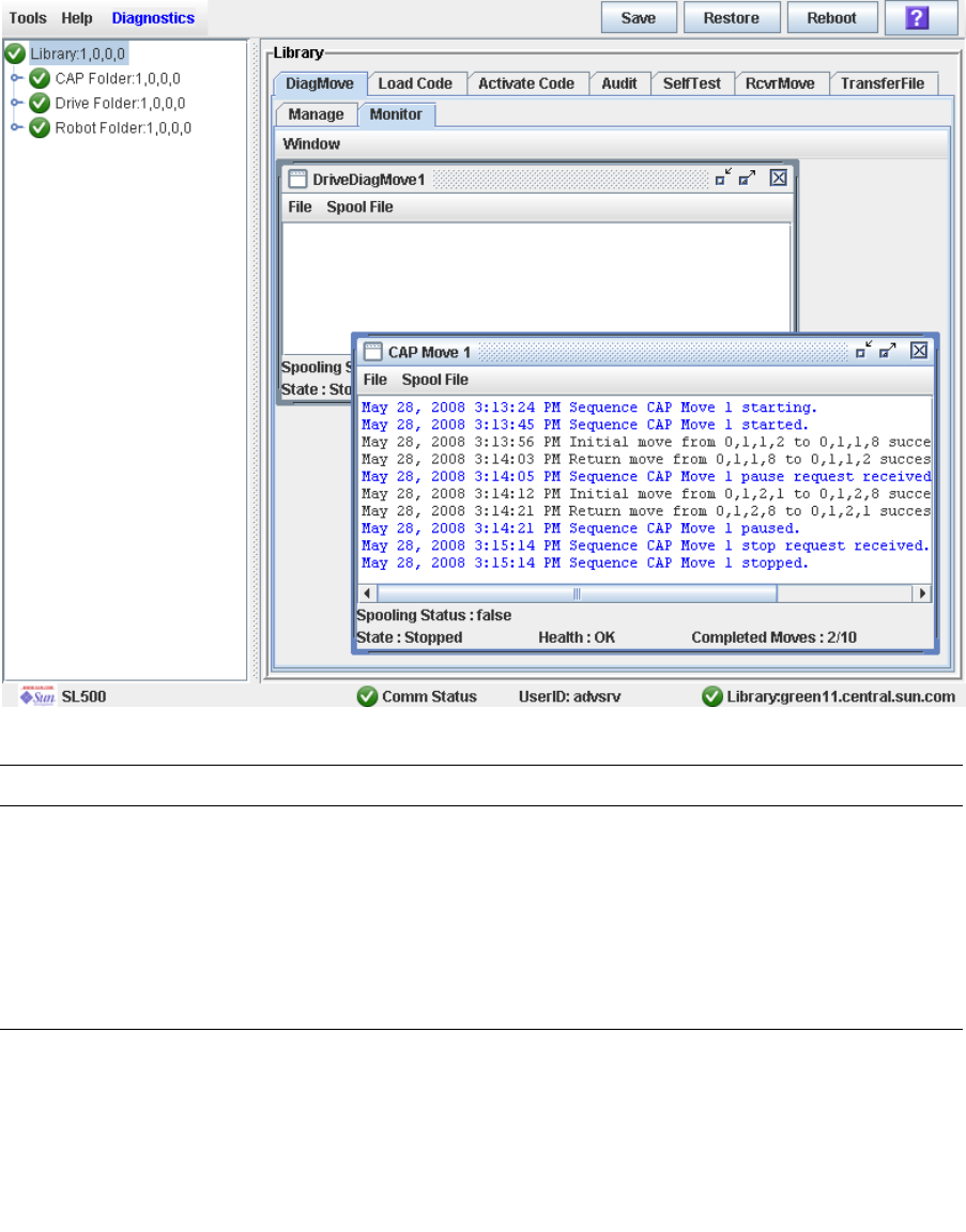
HandBot Utility Tasks
296 SL500 User’s Guide • July 2008 Revision: KA • 96116
▼ Monitor and Control Open Diagnostic Moves
Use this procedure to control and monitor the status of one or more open diagnostic
moves.
1. See “Start a Diagnostic Move” on page 294 for instructions on starting one or more
diagnostic moves.
2. Click the Monitor tab.
The Monitor screen appears, with one monitor window for each open move.
Each monitor window has the following status indicators:
Status Indicators Description Valid Values
Spooling Status Indicates if the move output is being
spooled to a file
True, False
State Current execution state of the move Running, pausing, paused,
stopping, stopped
Health Current health state of the move OK, warning, error
Completed moves Number of moves completed in the
requested move count

HandBot Utility Tasks
96116 • Revision: KA Chapter 7 SL Console Diagnostics and Utilities 297
3. Use the File menu in each Monitor window to perform any of the following
functions:
Select Option To Notes
File > Start Sequence Start
File > Pause Sequence Pause Stops all diagnostic moves, but maintains
the current location in the access order.
File > Stop Sequence Stop Stops a running or paused move.
File > Start Sequence Resume Resumes a paused move starting with
the last known location in the target
address range.
File > Clear Output Window Clear the messages
displayed in the monitor
window
Erases the previous message lines and
continues to fill the screen with new
messages.
Spool File > Start Spooling Spool Directs the move output to a file.
Spool File > Stop Spooling Stop spooling the move
output to a file
Stops directing the move output to the
spool file.

HandBot Utility Tasks
298 SL500 User’s Guide • July 2008 Revision: KA • 96116

96116 • Revision: KA 299
CHAPTER 8
SNMP Support
Simple Network Management Protocol is an application layer protocol that performs
network management operations over an Ethernet connection using a User Datagram
Protocol (UDP/IP).
The Simple Network Management Protocol allows:
■Libraries to inform the systems administrator of potential problems.
■Systems administrators to query the library for configuration, operation, and
statistical information.
The SL500 libraries support:
■SNMPv2c: read-only support primarily for machine status queries. With this version,
any information transmitted is not secure.
■SNMPv3: both read and write support; transmitted information is secure.
SNMP configuration requirements include:
■SL500 library firmware must be version 1067 or higher.
■SL Console software must be version FRS_2.95 or higher.
Trap Levels
SNMP traps provide data that are a source of log entries, containing:
■Severity (indications such as error or warning)
■Result codes (such as “0000 = success,” or “5010 = robotic posn error”)
■Activity string (such as “HLI move” or “CLI version print”)
■A descriptive text string
■Date and time
■Other information might include:
■Device address associated with the event
■User name associated with the activity (such as “HLI host,” “advsrv”)
■The interface-specific request identifier (such as “HLI000001”)
Trap levels are generally filtered to include only those traps that you wish to monitor.
These levels are specified when entering the trap information.

Port Control
300 SL500 User’s Guide • July 2008 Revision: KA • 96116
Trap or notification levels available at this time are listed in the table below:
Note – You can also set combinations of trap levels. For example, "1,2", "1,11", "1,2,11".
Port Control
Typically, SNMP uses user datagram protocol (UDP) ports:
■61 for the agent
■62 for the manager
UDP like TCP, runs on top of IP networks and is one of the core protocols in the
Internet protocol suite. UDP allows network-based devices to send short messages
faster and more efficiently for many lightweight and time-sensitive applications.
The basic protocol for communications between manager and agent is:
■The manager can send requests from any available port to the agent at port 161. The
agent then responds to that source port, to the requesting manager.
■The agent generates traps or notifications and sends them from any available port to
the manager at port 162.
Access Control
SNMPV2c community strings are capable of providing a form of access control in
SNMP. Because of this, the Sun StorageTek embedded agent will not allow community
strings to make changes to the library’s configuration.
The MIB file can be retrieved with either SNMPv2c or SNMPv3; however, because
SNMPv3 provides encryption capabilities and a stronger user identification, library
properties can be changed only with the SNMPv3 set command.
Using an administrative password also provides access control and authorization for
set command operations.
Traps, however, can be sent to recipients using either SNMPv2c or SNMPv3 by adding
entries to the Trap Recipient List.
Trap Level Number Description
Error 1 Error/System Log entries. Errors critical to library operation.
For example, Device inoperable: refers to the entire system.
Failure of a redundant component is not a Category 1.
Warning 2 Warning Log entries. Conditions that require attention. For
example, Device degraded: Refers to recoverable failures that
may allow the system to remain in use, but only in a
degraded mode.
11 11 SNMP Agent Start Up


SNMP Configuration and Usage Tasks
302 SL500 User’s Guide • July 2008 Revision: KA • 96116
▼ Add SNMP Users
Use this procedure to add an SNMP user.
1. Select Tools > System Detail.
2. Select the Library folder from the device tree.
3. Select SNMP > Add Users and enter the following details:
4. Click Apply.
The indexed SNMP users list is displayed at the bottom of the screen. There can be a
maximum of 20 users.
Version Version of the SNMP standard. The SL500 library supports:
■SNMPv2c of the simple network management protocol for
machine status queries. With this version, any information
transmitted is not secure.
■SNMPv3 of the simple network management protocol is
reserved for proprietary information. Because this version
supports encryption and stronger user identification it is
the preferred protocol for proprietary data.
Community (v2c
only)
Applications use community strings for access control. The
manager includes the community string in its SNMP
messages to an agent. The agent consequently can accept or
reject the operation. This can be a maximum of 31
alphanumeric characters.
UserName (v3
only)
SNMP user ID.
Auth (v3 only) Authentication protocol type (MD5 or SHA) string for users
and hosts receiving traps. One of the two primary SNMPv3
security protocols designed to reliably identify the integrity
of the originating party.
AuthPass (v3
only)
Authentication password of the user.
Priv (v3 only) Privacy protocol type (DES or AES): The other two primary
SNMPv3 security protocols are designed to protect
information within the message from disclosure.
PrivPass (v3 only) Encryption Password that is the private key for encryption.

SNMP Configuration and Usage Tasks
96116 • Revision: KA Chapter 8 SNMP Support 303
▼ Delete SNMP Users
Use this procedure to delete a SNMP user.
1. Select Tools > System Detail.
2. Select the Library folder from the device tree.
3. Select SNMP > Delete Users.
4. Enter the Index number of the SNMP user from the list.
5. Click Apply.
Verify the SNMP users list and make sure that the user is deleted.

SNMP Configuration and Usage Tasks
304 SL500 User’s Guide • July 2008 Revision: KA • 96116
▼ Add Trap Recipients
A recipient is a location on a manager where the SNMP agent sends traps. This location
is defined by the combination of either the IP address or DNS name and the port
number.
Use this procedure to add a trap recipient.
1. Select Tools > System Detail.
2. Select the Library folder from the device tree.
3. Select SNMP > Add Trap Recipient and enter the following details:
4. Click Apply.
The indexed trap recipients list is displayed at the bottom of the screen. This list
supports up to 20 recipients with no duplicate entries. Users must add themselves to
the recipients list to receive traps.
Host Server name where the SNMP software application resides.
TrapLevel See “Trap Levels” on page 299 for details.
Version Version of the SNMP standard. The SL500 library supports:
■SNMPv2c of the simple network management protocol for
machine status queries. With this version, any information
transmitted is not secure.
■SNMPv3 of the simple network management protocol is
reserved for proprietary information. Because this version
supports encryption and stronger user identification it is
the preferred protocol for proprietary data.
Community (v2c
only)
Agent community string. When set to public, requests coming
from any community string will be accepted.
TrapName (v3 only) Name of the trap recipient.
Auth (v3 only) Authentication protocol type (MD5 or SHA) string for users
and hosts receiving traps. One of the two primary SNMPv3
security protocols designed to reliably identify the integrity
of the originating party.
AuthPass (v3 only) Authentication password of the user.
Priv (v3 only) Privacy protocol type (DES or AES): The other two primary
SNMPv3 security protocols are designed to protect
information within the message from disclosure.
PrivPass (v3 only) Encryption Password that is the private key for encryption.
EngineID (v3 only) Engine Id is an administratively unique identifier of an
SNMP v3 engine used for identification, not for addressing
(Source: The Internet Society, RFC 3411). SNMP v3
authentication and encryption keys are generated based upon
the associated passwords and the engine ID. The engine ID is
a string of at most 31 hexadecimal characters, preceded with
0x.

SNMP Configuration and Usage Tasks
96116 • Revision: KA Chapter 8 SNMP Support 305
▼ Delete Trap Recipients
Use this procedure to delete a trap recipient.
1. Select Tools > System Detail.
2. Select the Library folder from the device tree.
3. Select SNMP > Delete Trap Recipients.
4. Enter the Index number of the trap recipient from the list.
5. Click Apply.
6. Verify the trap recipients list and make sure that the trap is deleted.

SNMP Configuration and Usage Tasks
306 SL500 User’s Guide • July 2008 Revision: KA • 96116
▼ Set Up Port Control
Use this procedure to set up SNMP port control.
1. Select Tools > System Detail.
2. Select the Library folder from the device tree.
3. Select SNMP > Port Control.
4. Enter the following information:
■Port—For SL500 tape library. Port 1B is the public access port; other ports are
unavailable on this library.
■Command
■Disable—Default. Agent trap requests are sent/received on LAN port:
■Enable—SNMP traps are enabled and the agent responds to gets from the clients.
5. Click Apply.
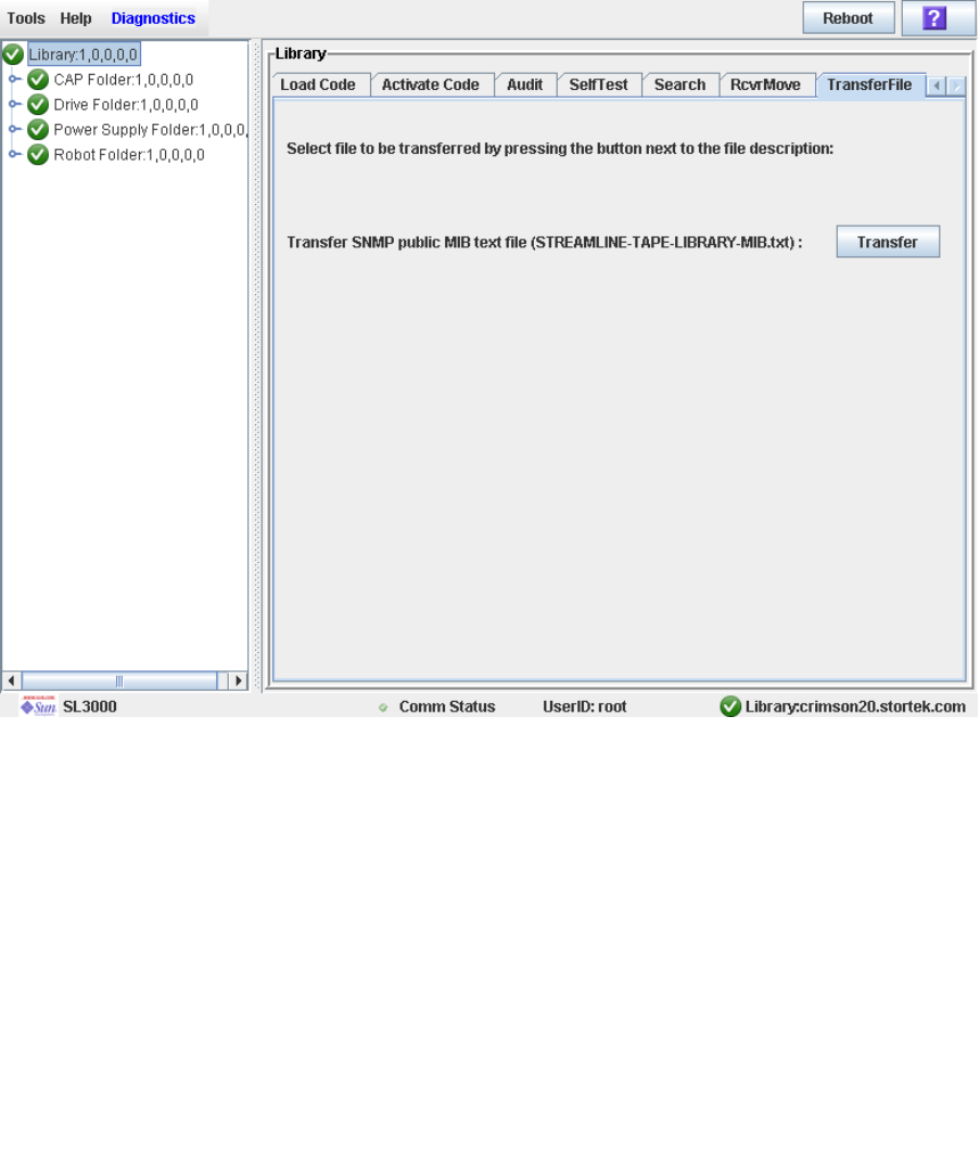
SNMP Configuration and Usage Tasks
96116 • Revision: KA Chapter 8 SNMP Support 307
▼ Transfer the Library MIB File
Use this procedure to copy the public SNMP management information base (MIB) file
to a specified location on your local PC or workstation. The file is saved as a text file.
You can e-mail the file to your Sun support representative to help diagnose problems
with the library.
1. Select Tools > Diagnostics,
2. Click the Library folder on the device tree.
The Library screen appears.
3. Click the TransferFile tab.
The MIB file transfer screen appears.
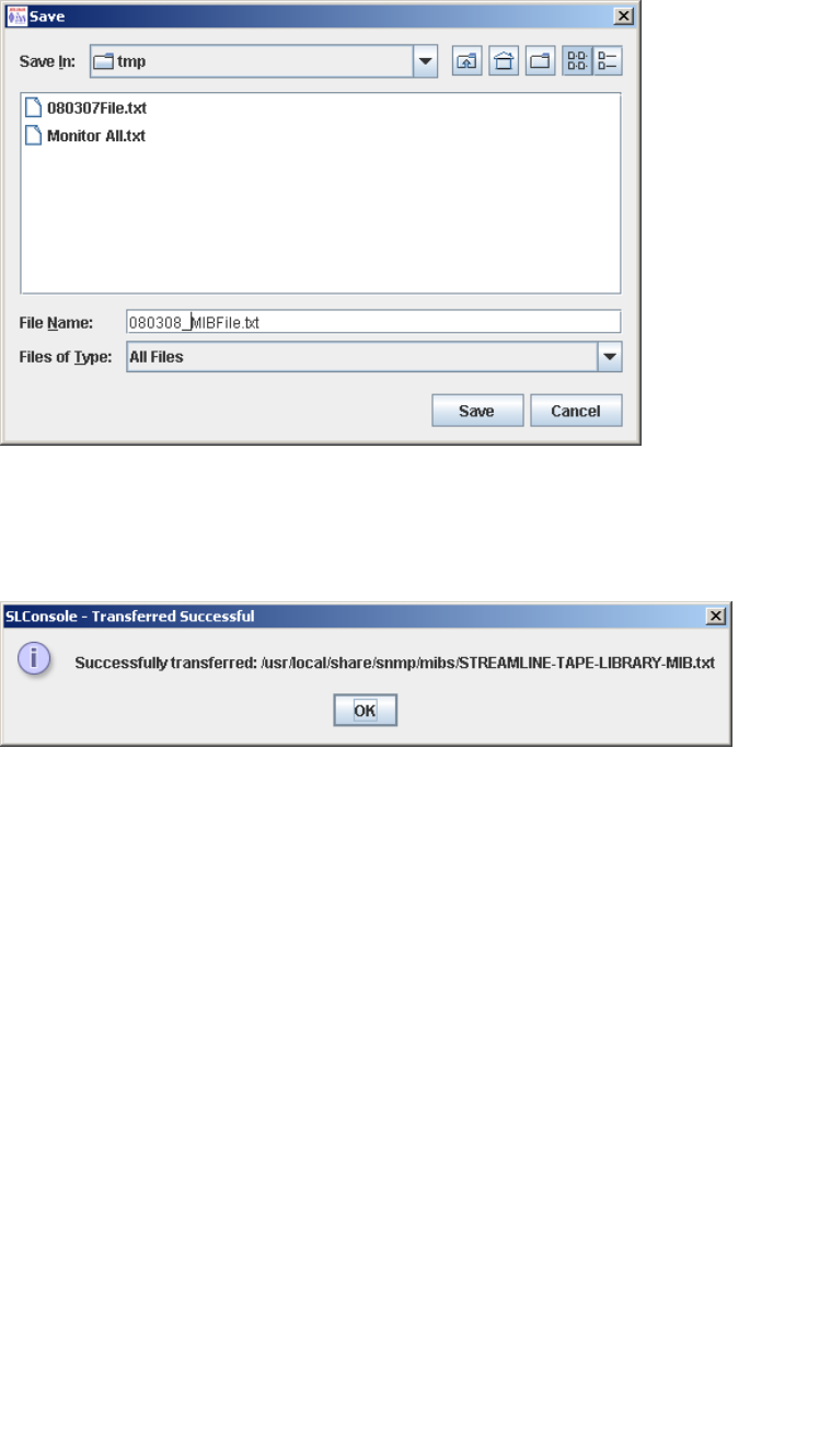
SNMP Configuration and Usage Tasks
308 SL500 User’s Guide • July 2008 Revision: KA • 96116
4. Click Transfer.
The Save popup appears.
5. Browse to the directory where you want to save the file, and enter the file name in
the File Name field. Be sure to give it a .txt suffix.
6. Click Save.
The data is saved to the specified file, and the Transferred Successful popup appears.
7. Click OK to dismiss the popup.

96116 • Revision: KA 309
CHAPTER 9
Manual Operations
When in manual mode of operation, the library is unavailable for host access. This may
be because the library has experienced an unrecoverable error or a library component
requires service or installation. When the library is in this mode, cartridge mounts and
dismounts require human intervention.
Library Safety
Thoroughly review the safety precautions in this section before attempting to enter the
library. It is essential that you follow proper safety procedures at all times.
Cards and Power Supply
The RLC card, SCSI (MPW/RLW) or Fibre Channel (MPU2) interface card, and the
power supply are housed inside protective modules to prevent you from coming into
contact with hazardous voltages and sensitive electronics.
Robotics
The software parks the robot by retracting it into the robotics unit module before the
front door can be opened to prevent the robot from being damaged.
When the front door is opened, power is removed from the robot.
Front Door
The front door must be opened with a key to ensure that the data is secure. If the door
is not fully closed, a sensor relays the condition to the software and the robot remains
disabled.


General Library Operation Tasks
96116 • Revision: KA Chapter 9 Manual Operations 311
General Library Operation Tasks
Task Page
Power Off the Library 312
Power On the Library 313
Return the Library to Ready Status 314
Open the Front Door (With Power) 315
Open the Front Door (Without Power) 316
Secure the Front Door (With Power) 318
Secure the Front Door (Without Power) 319

General Library Operation Tasks
312 SL500 User’s Guide • July 2008 Revision: KA • 96116
▼ Power Off the Library
Caution – Possible equipment or cartridge damage or data loss. If you power-off the library
without performing the following procedure, you risk possible equipment or cartridge
damage or loss of data.
1. Make sure all jobs have completed processing.
2. Quiesce the library to make sure the library and tape drives are not in use.
Note – Refer to your client server software publication for instructions.
3. Move the power-on/off switch to the OFF position (0).

General Library Operation Tasks
96116 • Revision: KA Chapter 9 Manual Operations 313
▼ Power On the Library
To power on the library:
1. Close and lock the front door if the door is open.
2. Press the power switch (on the top right corner of the back of the library) to the ON
(1) position.

General Library Operation Tasks
314 SL500 User’s Guide • July 2008 Revision: KA • 96116
▼ Return the Library to Ready Status
To return the library to ready status:
1. Make sure cartridges are inserted correctly in the storage cells or tape drives and that
they do not block the path of the X table assembly.
2. Close the door and lock it by turning the key counterclockwise; put the key in a safe
place.
3. Make sure the power switch are set to the ON position (1).
4. Check the status display of the SL Console to make sure the library goes to Ready
Status when initialization and audit are complete.
5. Enter the system command to place all tape drives online.
6. When all tape drives are online, enter the command to place the library online.

General Library Operation Tasks
96116 • Revision: KA Chapter 9 Manual Operations 315
▼ Open the Front Door (With Power)
To open the front door when library power exists:
1. Press the Open Door button on the keypad.
The software allows the current job to complete.
The software retracts the robot into the robotic unit to prevent the robot from being
damaged and to prepare it for servicing.
2. When the Open Door indicator turns on, use the key to open the door.
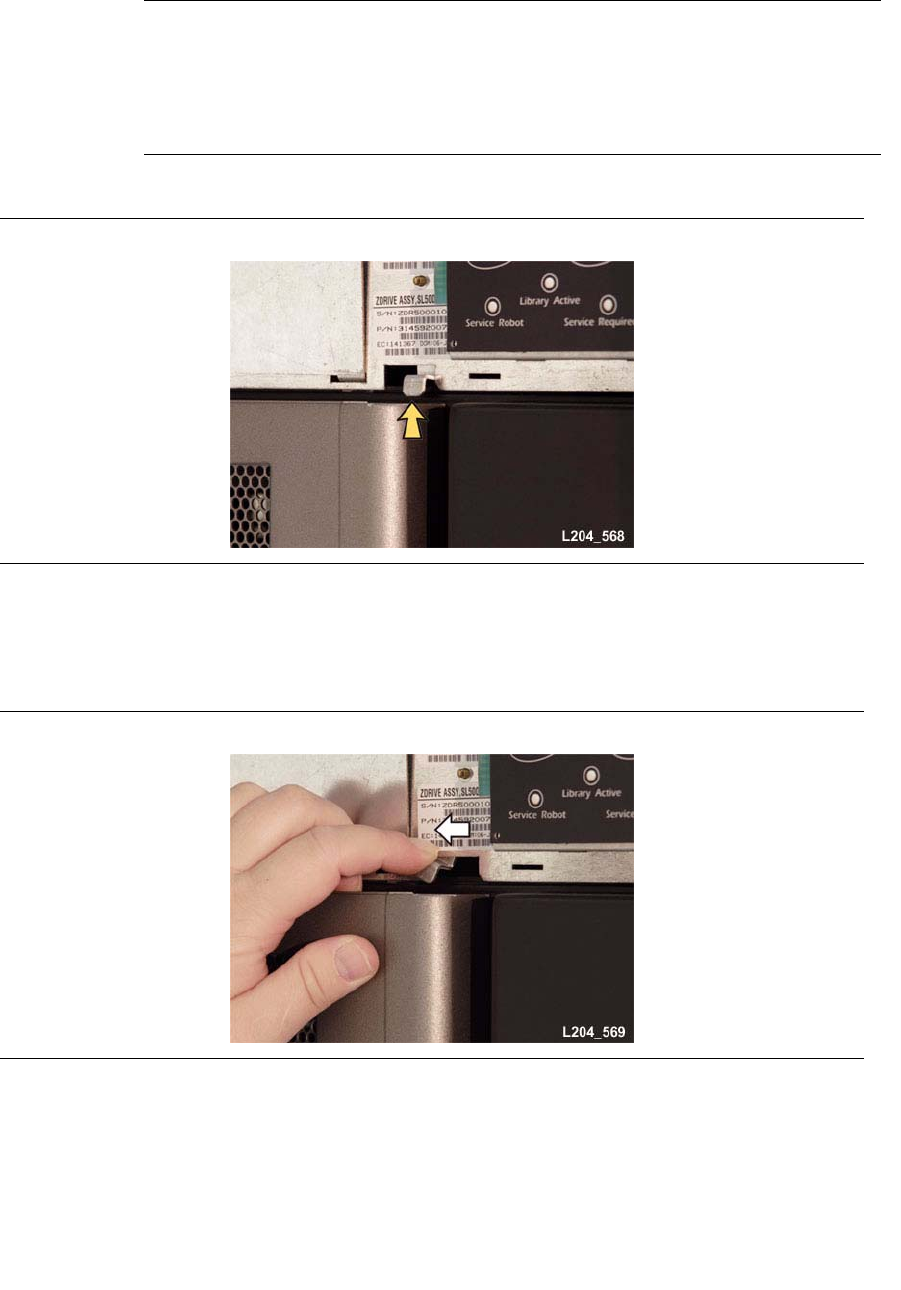
General Library Operation Tasks
316 SL500 User’s Guide • July 2008 Revision: KA • 96116
▼ Open the Front Door (Without Power)
To open the front door when no library power exists:
Note – You must manually move the robotics park lever (beneath the facade and to the
bottom left of the keypad) to the left position so that you can open the door with the
key. Under normal conditions, the lever signifies that the robot is parked inside the
robotics unit at the top of the library, and the door can be safely opened. When no
power exists, the robot is not actually parked, but you will be able to open the door
when you move the lever to the left.
In the following picture, the lever is not in the parked position.
1. Press the power switch on the back of the library to the OFF position.
2. Remove the robotic facade from the top of the library by gently pulling the facade
from side to side to pull the ball studs away from the clips. You might have to use a
screwdriver to gently pry it off.

General Library Operation Tasks
96116 • Revision: KA Chapter 9 Manual Operations 317
Warning – Possible Physical Injury. Possible injury to finger: Make sure that
your finger is completely to the left in the next step so that it will not be pinched
when the door locking lever extends as shown in the lower picture.
3. While using one hand to move the robotics park lever to the left, use your other hand
to unlock the door with the key.

General Library Operation Tasks
318 SL500 User’s Guide • July 2008 Revision: KA • 96116
▼ Secure the Front Door (With Power)
To secure the front door when library power exists, push it closed and use the key to
lock it.
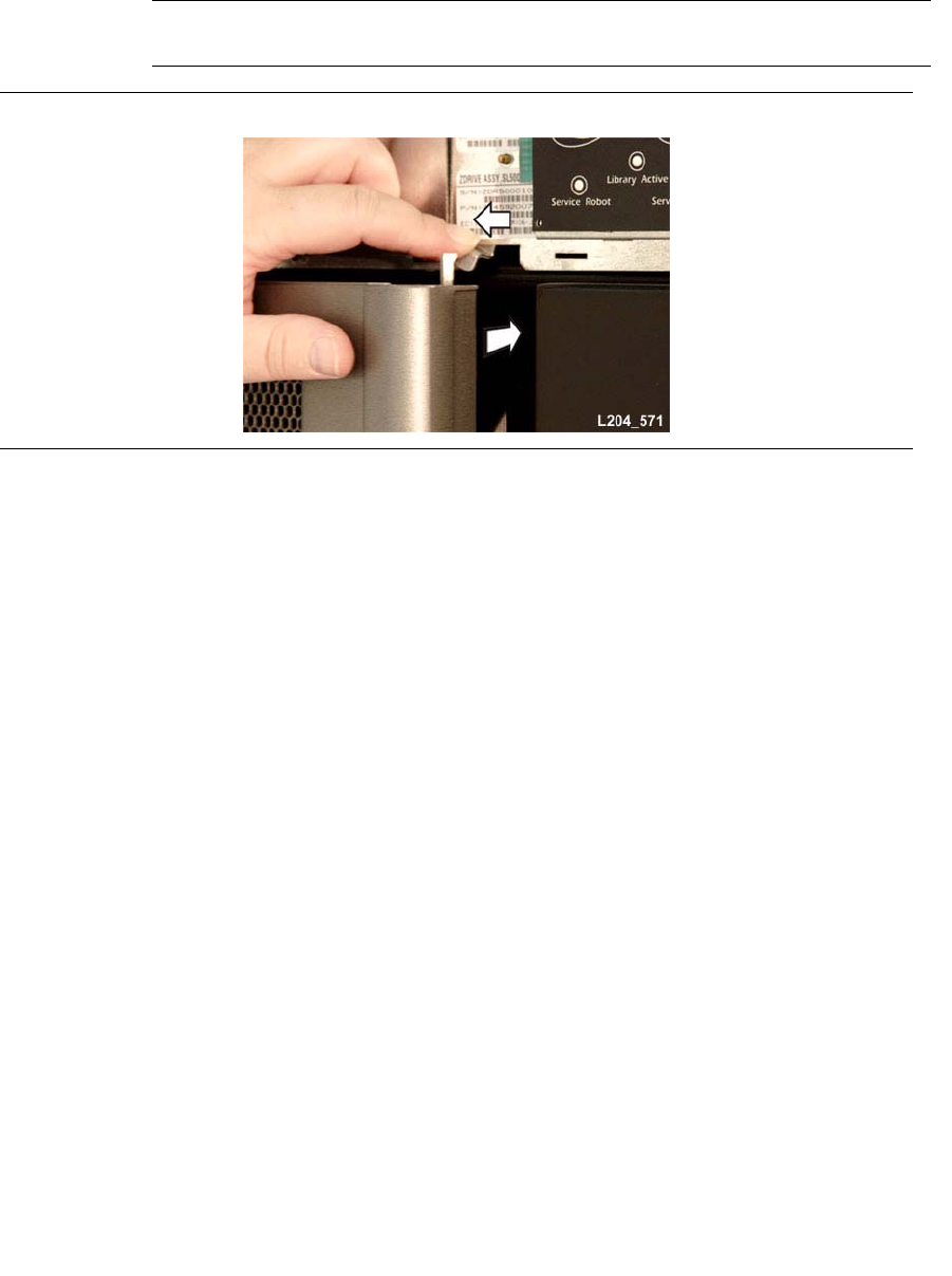
General Library Operation Tasks
96116 • Revision: KA Chapter 9 Manual Operations 319
▼ Secure the Front Door (Without Power)
To secure the front door when no library power exists:
1. Remove the robotic facade from the top of the library by gently pulling the facade
from side to side to pull the ball studs away from the clips. You might have to use a
screwdriver to gently pry it off.
Caution – Possible component damage: Note the door locking lever protruding from the
top of the door. Do not let it hit the robotics park lever when you close the door.
2. While using one hand to move the robotics park lever to the left, use your other hand
to close the door.
3. While still holding the door shut, release the robotics park lever.
4. Use the key to lock the door.
5. The robotics lever automatically moves to the right when the door locking lever
retracts.

Cartridge Handling Tasks
320 SL500 User’s Guide • July 2008 Revision: KA • 96116
Cartridge Handling Tasks
Task Page
Locate and Remove a Cartridge 321
Insert Cartridges into Storage Cells 322
Insert a Cartridge into a Tape Drive 324
Remove a Cartridge from a Tape Drive 325
Remove a Cartridge from the Gripper Assembly 327
Replace a Cleaning Cartridge 325

Cartridge Handling Tasks
96116 • Revision: KA Chapter 9 Manual Operations 321
▼ Locate and Remove a Cartridge
To locate a particular cartridge inside the library:
1. Open the door.
2. Locate the particular cartridge by its VOLID (volume ID) label and storage cell.
3. Remove the cartridge from the cell by sliding the cartridge out.
4. Close the library door.

Cartridge Handling Tasks
322 SL500 User’s Guide • July 2008 Revision: KA • 96116
▼ Insert Cartridges into Storage Cells
Depending on the version and configuration of your library, some storage cells cannot
be used. See Appendix A, “SL500 Wall Diagrams and Specifications” for details.
Note – You do not have to insert a cartridge into every storage cell. The library
automatically audits cartridges and empty cells as part of its initialization routine.
Note – LTO cartridges can be placed in either LTO arrays or mixed-media arrays.
SDLT/DLT-S4 cartridges can only be placed in mixed-media arrays, not LTO arrays.
Caution – Inserting the cartridges correctly is critical for library operation. If you do
not orient the cartridges correctly or do not insert them all the way into the storage
cells, the library might fail, and the SL Console might display an error message. Make
sure you insert the cartridge inside the array, not above or beneath it. FIGURE 9-1
shows the correct way to insert cartridges into the magazine.
1. Check the cartridges to make sure they are correctly labeled.
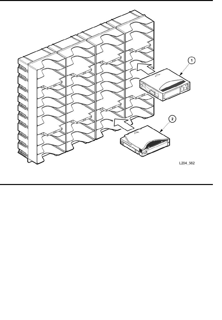
Cartridge Handling Tasks
96116 • Revision: KA Chapter 9 Manual Operations 323
2. Insert as many cartridges into the library as you want and as your configuration
allows, making sure you seat them all the way into the storage cells.
.
FIGURE 9-1 Insert Mixed Media Cartridges into Arrays
1. SDLT/DLT-S4 cartridge
2. LTO cartridge
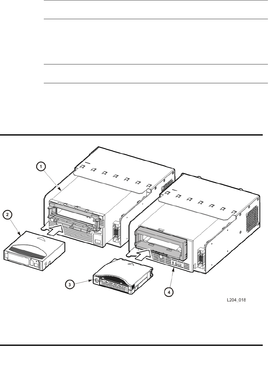
Cartridge Handling Tasks
324 SL500 User’s Guide • July 2008 Revision: KA • 96116
▼ Insert a Cartridge into a Tape Drive
Use this procedure to manually insert a cartridge into a tape drive.
Note – LTO cartridges can be placed in either LTO arrays or mixed-media arrays.
SDLT/DLT-S4 cartridges can only be placed in mixed-media arrays, not in LTO arrays.
1. Obtain the VOLID label, location, and tape drive number from the server console.
2. Open the door.
3. Locate the cartridge (see “Locate and Remove a Cartridge” on page 321).
Caution – Potential equipment damage. You must insert the cartridge properly or you
will damage the tape drive.
4. Hold the cartridge so that the VOLID is facing you and can be read from right to left.
5. Insert the cartridge into the tape drive.
6. Close the library access door.
FIGURE 9-2 Insert Cartridge into Drive
1. SDLT/DLT-S4 Drive
2. SDLT/DLT-S4 Cartridge
3. LTO Cartridge
4. LTO Drive
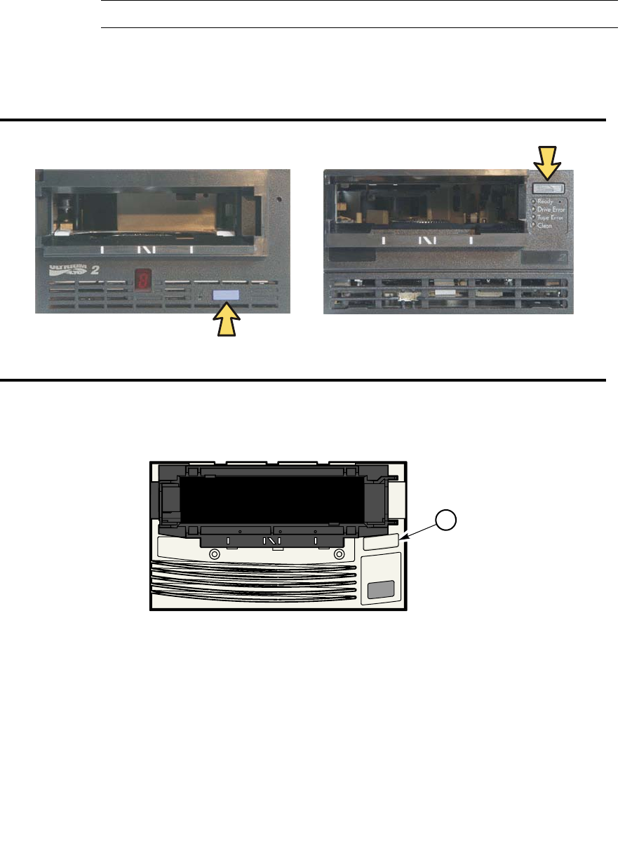
Cartridge Handling Tasks
96116 • Revision: KA Chapter 9 Manual Operations 325
▼ Remove a Cartridge from a Tape Drive
To manually remove a cartridge from a tape drive:
1. Obtain the tape drive number from the server console.
2. Open the door and locate the appropriate tape drive.
Caution – Possible data loss. Failure to perform the next step could result in data loss.
3. Press the Unload button on the tape drive and wait approximately 12 seconds until
the operation completes.
FIGURE 9-3 Remove a Cartridge from an LTO Tape Drive
4. Gently pull the cartridge from the tape drive.
5. Store the cartridge in an empty storage cell or outside the library.
FIGURE 9-4 Remove a Cartridge from an SDLT Tape Drive
1. SDLT Unload Button
L204
_
007
IBM HP
L204
_
573
SDLT
1


Cartridge Handling Tasks
96116 • Revision: KA Chapter 9 Manual Operations 327
▼ Remove a Cartridge from the Gripper Assembly
The hand assembly can be in any position when the library loses power. Before you can
remove the cartridge, the hand assembly must be facing the front left arrays and
aligned with an empty storage cell.
See “Open the Front Door (Without Power)” on page 316.
If the hand assembly is facing right:
1. Gently turn the hand to the left.
2. Slide the hand assembly along the rail until the gripper is positioned across from an
empty storage cell and close to you.
3. Continue with the following steps.
If the hand assembly is facing left:
1. Turn the gripper belt (FIGURE 9-5) to extend the gripper until the release screw is
accessible.
2. Use a small, flat-blade screwdriver to turn the screw 1/4 turn clockwise until the
cartridge is released.
3. Push the cartridge into a storage cell.
4. Gently push the gripper back into the hand.
5. Slide the hand assembly toward the back of the library.
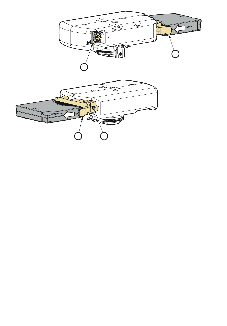
Cartridge Handling Tasks
328 SL500 User’s Guide • July 2008 Revision: KA • 96116
6. Remove the cartridge from the storage cell, or leave it there.
FIGURE 9-5 Manual Release Screw
1. Gripper belt and pulleys
2. Release screw
3. Gripper
L204
_
22
7
2
3
2
1

Cartridge Handling Tasks
96116 • Revision: KA Chapter 9 Manual Operations 329
▼ Replace a Cleaning Cartridge
Cleaning cartridges have a limited life span. Refer to your tape drive publication to
determine how many times a cleaning cartridge should be used. When the usage count
exceeds its limit, you must replace it with a new one. You can use the SL Console to
eject the cleaning cartridge to the CAP.
To replace a cleaning cartridge:
1. Open the door.
2. Remove the expired cleaning cartridge from its reserved cell.
3. Insert the new cleaning cartridge into that cell.
Note – Refer to TABLE B-1 to make sure your cartridge has the correct vendor and
usage label.
4. Close the library door.
The SL Console status display shows that initialization tests are running.
5. Wait until the initialization tests complete before you perform another task.

Cartridge Handling Tasks
330 SL500 User’s Guide • July 2008 Revision: KA • 96116
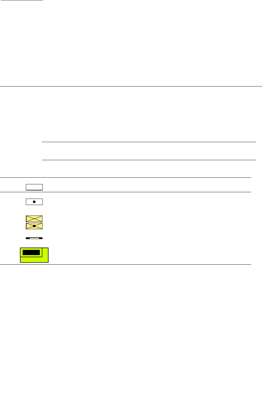
96116 • Revision: KA 331
APPENDIX A
SL500 Wall Diagrams and
Specifications
This appendix provides the following diagrams and tables:
■“LTO Configurations” on page 332
■“Mixed-Media Configurations” on page 337
■“Specifications” on page 342
Use the legend in TABLE A-1 for all diagrams in this appendix.
Note – Your tape management software might conflict with the following information.
Refer to your software publication for unique information.
TABLE A-1 Cell Figure Legend
Storage cells available for customer data cartridge
Cells reserved for cleaning and diagnostic cartridges (can be
configured for data cartridges)
Cells only available when an expansion module is installed. If this is
the lowest module in the rack, these cells are not available.
Array targets
Tape drives

LTO Configurations
332 SL500 User’s Guide • July 2008 Revision: KA • 96116
LTO Configurations
The following figures show LTO storage cell and tape drive locations.
■FIGURE A-1, “Base Module LTO Cells” on page 333 shows a library with only a Base
Module.
■FIGURE A-2, “LTO Cell Locations for Firmware Site Mapping” on page 334 shows a
library with a Base Module that has nine reserved cells, one Drive Expansion
Module, and one Cartridge Expansion Module.
■FIGURE A-3, “LTO Cell Locations for SCSI Element Numbering Mapping” on
page 335 shows a library with a Base Module that has two reserved cells, one Drive
Expansion Module, and one Cartridge Expansion Module. The storage cell
numbering begins with the first cell after the reserved cells in column 1. The figure
shows two reserved cells, but there could be more. If the reserved cells are
configured as storage cells, the top cell (row 1) would be 1.
■FIGURE A-4, “LTO Cells for Back Wall of Cartridge Expansion Module” on page 336
shows the cell capacity of a Cartridge Expansion Module according to which type of
module is installed above and below it.
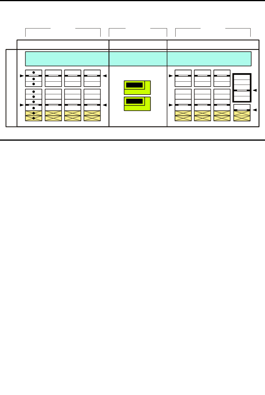
LTO Configurations
96116 • Revision: KA Appendix A SL500 Wall Diagrams and Specifications 333
FIGURE A-1 Base Module LTO Cells
LEFT SIDE WALL RIGHT SIDE WALLREAR WALL
COLUMNS COLUMNSCOLUMN
1 52 63 794 8
M
O
D
U
L
E
1
CAP
111
R
O
W
S
R
O
W
S
1
1
2
222 2
3
6
333
444 4
7
555 5
8
666
777
888
999
L204
_
004
Robot Park Zone
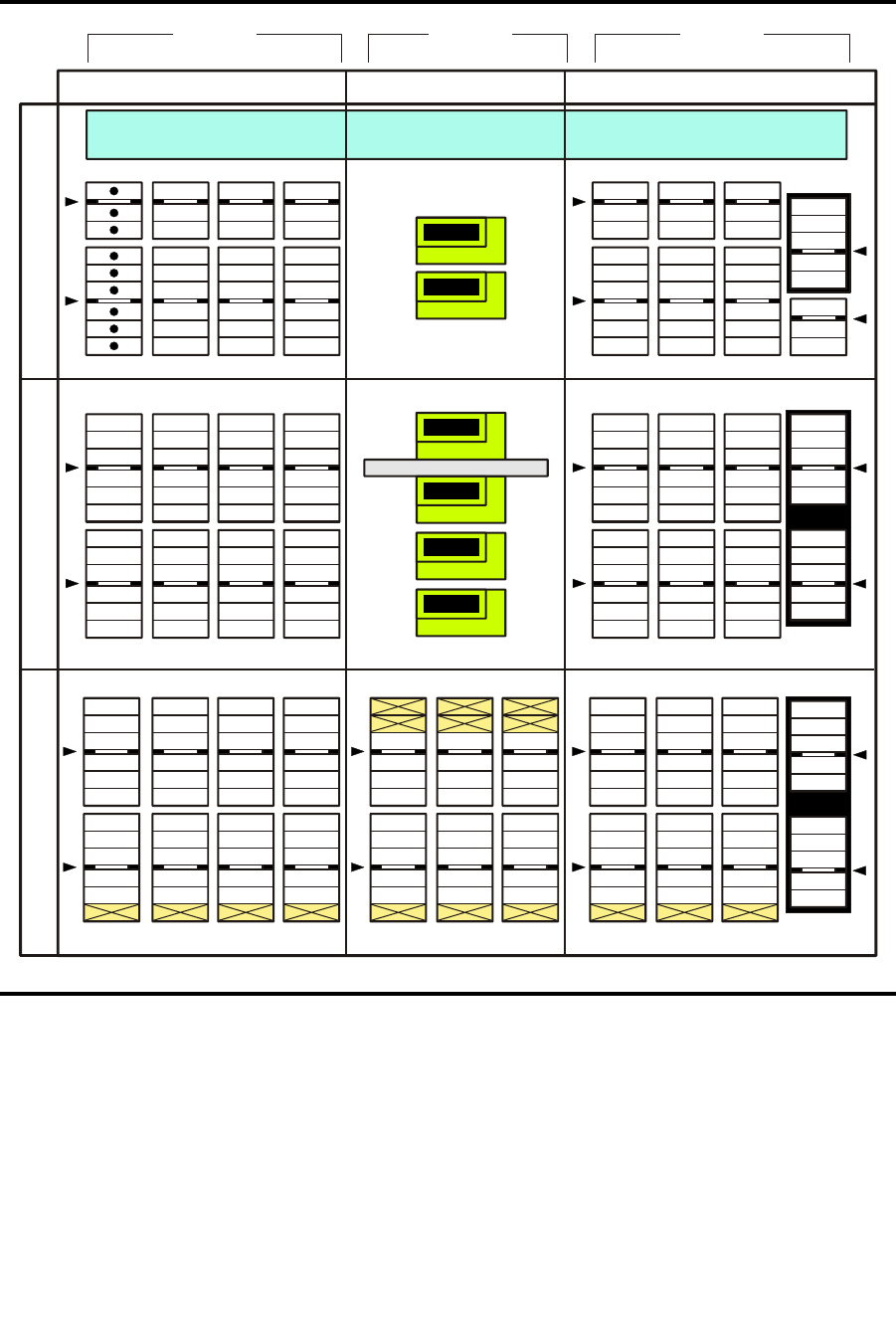
LTO Configurations
334 SL500 User’s Guide • July 2008 Revision: KA • 96116
FIGURE A-2 LTO Cell Locations for Firmware Site Mapping
1
3
2
4
Expansion Identification Label
M
O
D
U
L
E
3
15
263 7
10 1194 8
1
2
1
1 1
1
2
2 2
2
3
313
3
4
424
4
5
535
5
6
646
6
7
757
7
8
868
8
9
979
9
10
10 8 10
10
11
11 9 11
11
12 12
Robot Park Zone
CAP
CAP
CAP
1 1
R
O
W
S
R
O
W
S
1
2 2 2
3
6
3 3
4 4 4
7
5 5 5
8
6 6
7 7
8 8
9 9
LEFT SIDE WALLS
COLUMNS COLUMNSCOLUMN
RIGHT SIDE WALLSREAR WALLS
M
O
D
U
L
E
1
M
O
D
U
L
E
2
1 52 63 794 8
L204
_
010
1
1
2
2
3
3
4
4
5
5
6
6
7
7
8
8
9
9
10
10
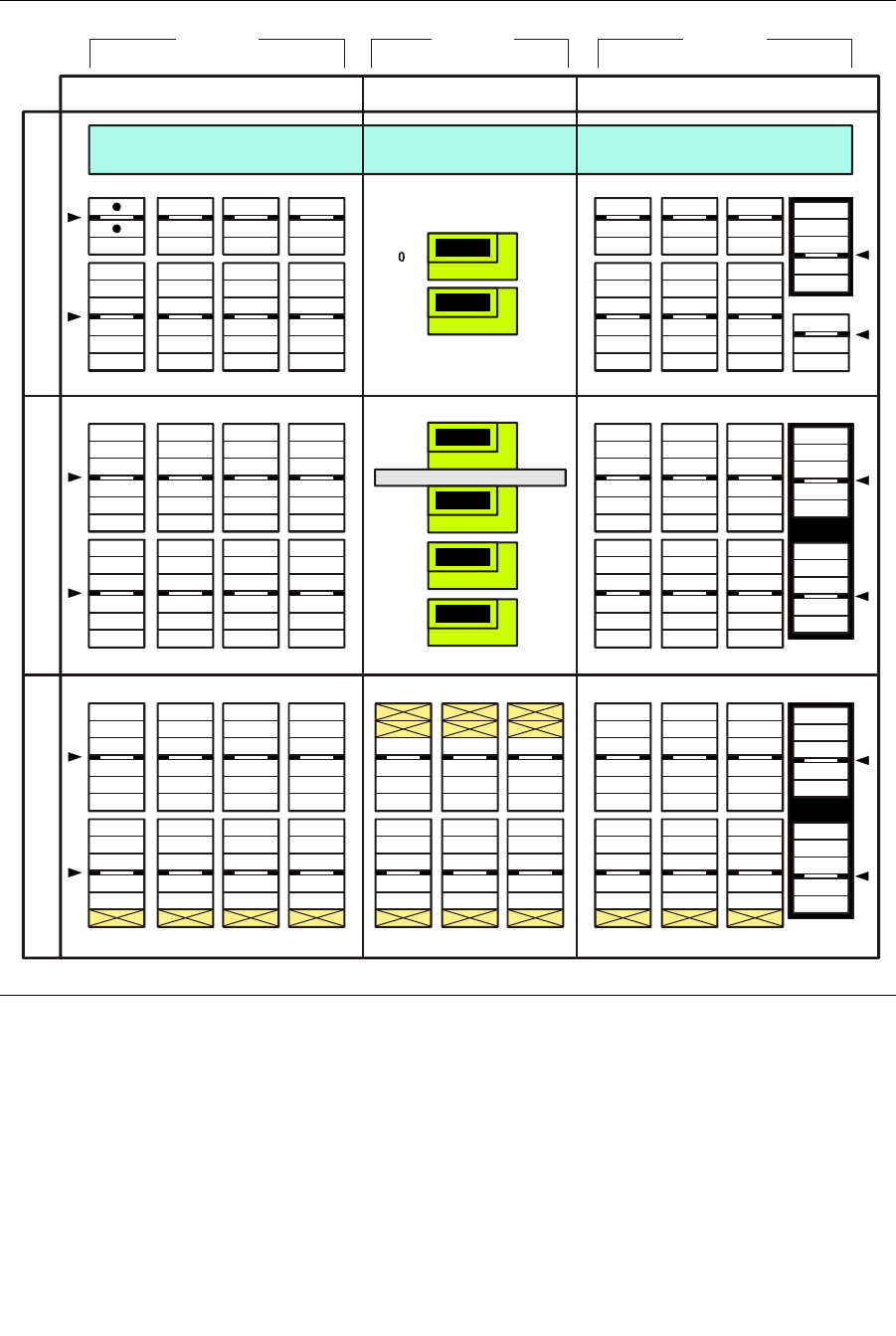
LTO Configurations
96116 • Revision: KA Appendix A SL500 Wall Diagrams and Specifications 335
FIGURE A-3 LTO Cell Locations for SCSI Element Numbering Mapping
2
4
3
5
Expansion Identification Label
1
Robot Park Zone
CAP
CAP
CAP
77
160
88
170
89
171
100
181
101
182
112
192
62
65
149
1
7
76
159
1
5
LEFT SIDE WALLS
COLUMNS COLUMNSCOLUMNS
RIGHT SIDE WALLSREAR WALLS
M
O
D
U
L
E
1
M
O
D
U
L
E
2
M
O
D
U
L
E
3
1
1
5
5
2
2
6
6
3
3
7
7
9
10 119
4
4
8
8
L204
_
009
15
25
113
220
193
125
231
202
137
242
211
6
16
124
230201
136
241210
148
252219
83517 4426 53
16 4325 5234 61 64
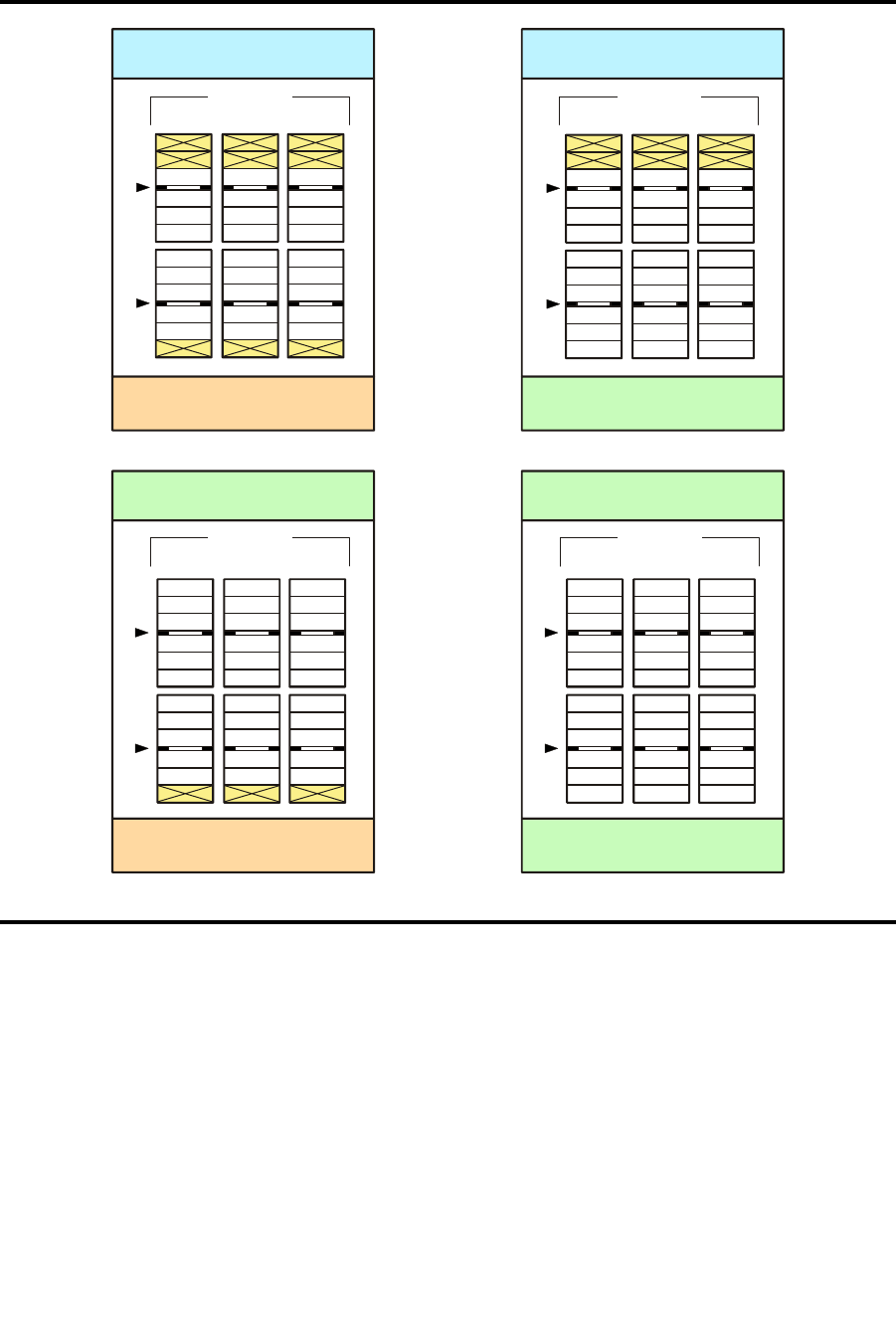
LTO Configurations
336 SL500 User’s Guide • July 2008 Revision: KA • 96116
FIGURE A-4 LTO Cells for Back Wall of Cartridge Expansion Module
Base or Drive Expansion Module
Installed Above CEM
No Module
Installed Below CEM
10 119
1
2
3
4
5
6
7
8
9
COLUMNS
1
2
3
4
5
6
7
8
9
10
11
Cartridge Expansion Module
Installed Above CEM
No Module
Installed Below CEM
10 119
COLUMNS
1
2
3
4
5
6
7
8
9
10
11
12
Cartridge Expansion Module
Installed Above CEM
10 119
COLUMNS
Base or Drive Expansion Module
Installed Above CEM
Cartridge Expansion Module
Installed Below CEM
10 119
1
2
3
4
5
6
7
8
9
10
COLUMNS
L204
_
556
Cartridge Expansion Module
Installed Below CEM

Mixed-Media Configurations
96116 • Revision: KA Appendix A SL500 Wall Diagrams and Specifications 337
Mixed-Media Configurations
The following figures show mixed-media storage cell and tape drive locations.
■FIGURE A-5, “Base Module Mixed-Media Cells” on page 338 shows a library with
only a Base Module.
■FIGURE A-6, “Mixed-Media Firmware Cell Mapping” on page 339 shows a library
with a Base Module that has eight reserved cells, one Drive Expansion Module, and
one Cartridge Expansion Module.
■FIGURE A-7, “Mixed-Media SCSI Element Numbering Mapping” on page 340 shows
a library with a Base Module that has two reserved cells, one Drive Expansion
Module, and one Cartridge Expansion Module. The storage cell numbering begins
with the first cell after the reserved cells in column 1. The figure shows two reserved
cells, but there could be more. If the reserved cells are configured as storage cells, the
top cell (row 1) would be 1.
■FIGURE A-8, “Mixed-Media Cells for Back Wall of Cartridge Expansion Module” on
page 341 shows the cell capacity of a Cartridge Expansion Module according to
which type of module is installed above and below it.
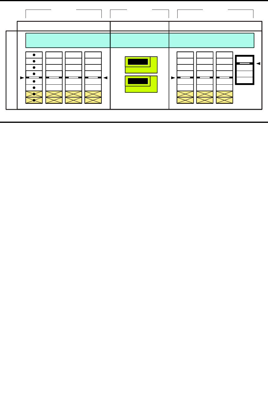
Mixed-Media Configurations
338 SL500 User’s Guide • July 2008 Revision: KA • 96116
FIGURE A-5 Base Module Mixed-Media Cells
LEFT SIDE WALL RIGHT SIDE WALLREAR WALL
COLUMNS COLUMNSCOLUMN
1 52 63 794 8
M
O
D
U
L
E
1
CAP
1 11 1
R
O
W
S
R
O
W
S
1
2
2 22
2
3 33
3
4 44
4
5 55
6 66
7 77
8 88
L204
_
558
Robot Park Zone
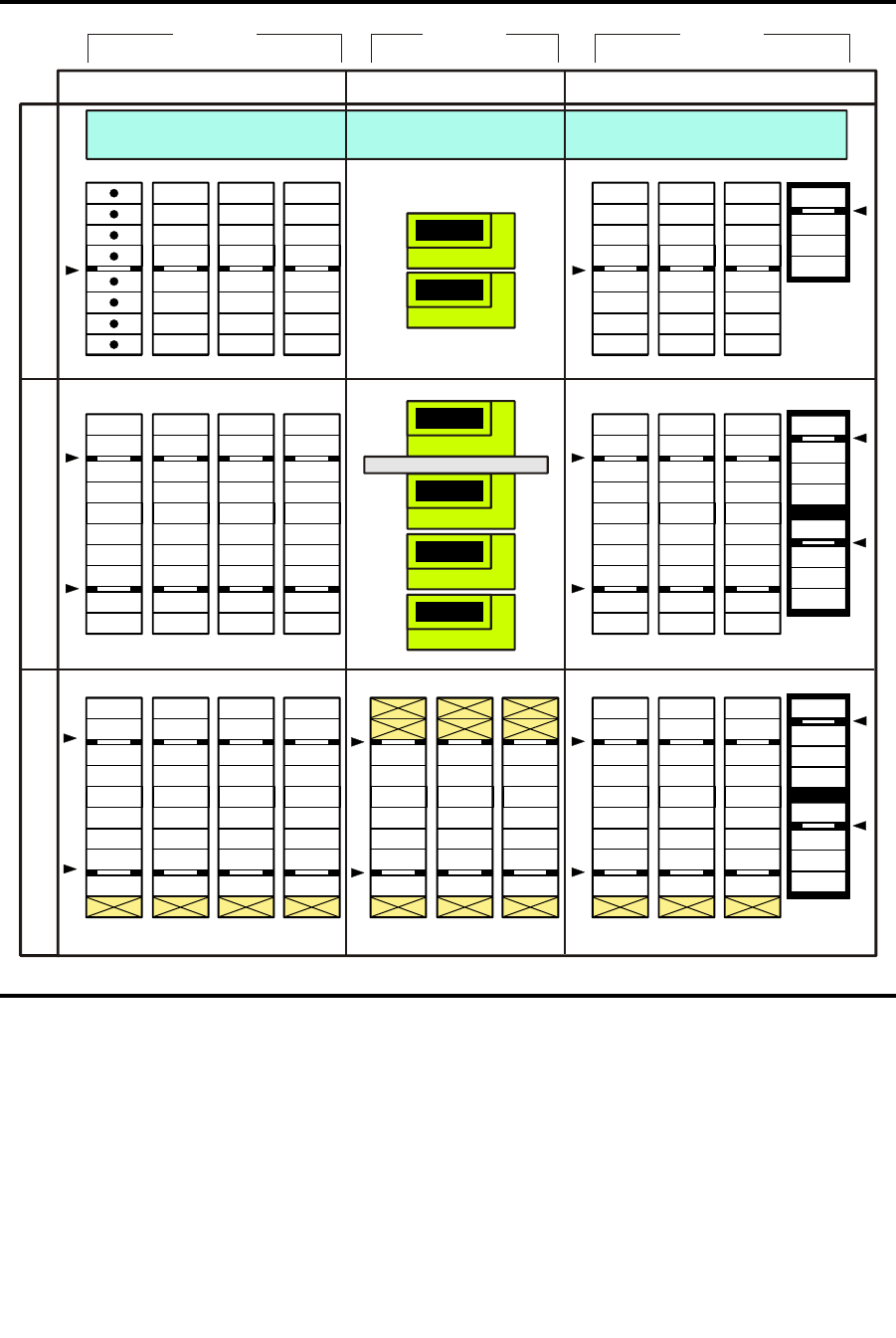
Mixed-Media Configurations
96116 • Revision: KA Appendix A SL500 Wall Diagrams and Specifications 339
FIGURE A-6 Mixed-Media Firmware Cell Mapping
1
3
2
4
Expansion Identification Label
M
O
D
U
L
E
3
15
263 7
10 1194 8
1
2
1 1
1
1
2 2
2
2
3 3
3
31
4 4
4
42
5 5
5
53
6 6
6
64
7 7
7
75
8 8
8
86
9 9
9
97
10 10
Robot Park Zone
CAP
CAP
CAP
R
O
W
S
R
O
W
S
1
2
3
4
LEFT SIDE WALLS
CO
LUMN
SCO
LUMN
SCO
LUMN
RIGHT SIDE WALLSREAR WALLS
M
O
D
U
L
E
1
M
O
D
U
L
E
2
1 52 63 794 8
L204
_
559
1
1
2
2
3
3
4
4
5
5
6
6
7
7
8
8
1
2
3
4
5
6
7
8
1
2
3
4
5
6
7
8
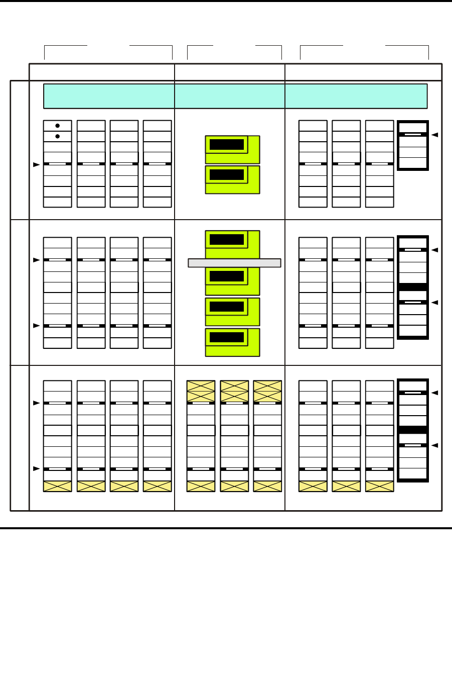
Mixed-Media Configurations
340 SL500 User’s Guide • July 2008 Revision: KA • 96116
FIGURE A-7 Mixed-Media SCSI Element Numbering Mapping
2
4
3
5
Expansion Identification Label
M
O
D
U
L
E
3
15
263 7
10 1194 8
0
1
1
6
71523 313947
14 22 30 38 46 54
55
125 134 143 152 182 191 200
161 168 175
65 75 85 95 105 115
64
133 142 151 160 190 199 208167 174 181
74 84 94 104 114 124
Robot Park Zone
CAP
CAP
CAP
R
O
W
S
R
O
W
S
1
4
LEFT SIDE WALLS
COLUMNS COLUMNSCOLUMN
RIGHT SIDE WALLSREAR WALLS
M
O
D
U
L
E
1
M
O
D
U
L
E
2
1 52 63 794 8
L204
_
560
5
13
12
20
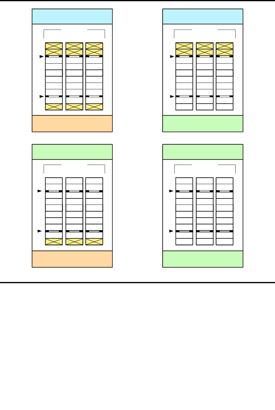
Mixed-Media Configurations
96116 • Revision: KA Appendix A SL500 Wall Diagrams and Specifications 341
FIGURE A-8 Mixed-Media Cells for Back Wall of Cartridge Expansion Module
Base or Drive Expansion Module
Installed Above CEM
No Module
Installed Below CEM
10 119
COLUMNS
Cartridge Expansion Module
Installed Above CEM
No Module
Installed Below CEM
10 119
COLUMNS
Cartridge Expansion Module
Installed Above CEM
10 119
COLUMNS
Base or Drive Expansion Module
Installed Above CEM
Cartridge Expansion Module
Installed Below CEM
10 119
COLUMNS
L204
_
561
Cartridge Expansion Module
Installed Below CEM
11
2 2
3 3
1 1
4 4
2 2
5 5
3 3
6 6
4 4
7 7
5 5
8 8
6 6
9 9
10
7 7
8

Specifications
342 SL500 User’s Guide • July 2008 Revision: KA • 96116
Specifications
The following pages provide the following specifications:
■“Library and Rack Dimensions” on page 343
■“Library and Rack Clearances” on page 344
■“Library Component Weights” on page 345
■“Library Environment Specifications” on page 345
■“Power Specifications” on page 346
For more specific tape drive and cartridge information, refer to the vendor Web site or
documentation.
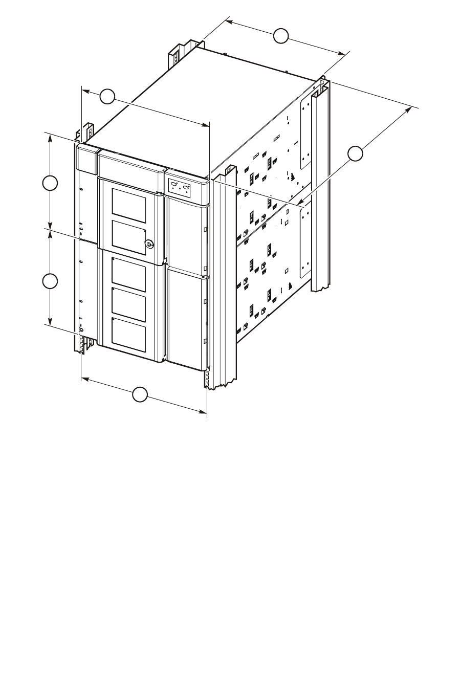
Specifications
96116 • Revision: KA Appendix A SL500 Wall Diagrams and Specifications 343
FIGURE A-9 Library and Rack Dimensions
1. 48.3 cm (19.0 in.) width of front of Base Module with flange
2. 35.6 cm (14.0 in.) height of Base Module
3. 35.6 cm (14.0 in.) height of expansion module
4. 46.5 cm (18.3 in.) distance between rack holes
5. Original design modules: 60.9 cm (24.0 in.) to 86.4 cm (34.0 in.), optimally 74 cm (29 in.) front to rear
rack mounting distance
EZ install modules: 55.9 cm (22.0 in.) to 78.7 cm (31.0 in.), optimally 66 cm (26 in.) front to rear rack
mounting distance (with optional extensions, depths up to 94 cm [37 in.])
6. 44.5 cm (17.5 in.) width of back of Base Module
L204_045
2
3
6
1
4
5
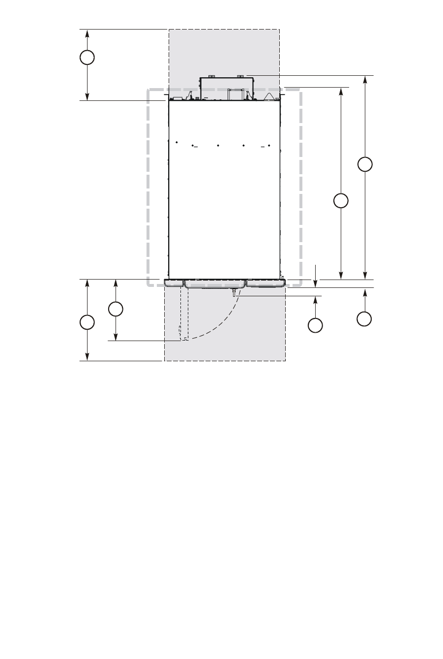
Specifications
344 SL500 User’s Guide • July 2008 Revision: KA • 96116
FIGURE A-10 Library and Rack Clearances
1. 60.9 cm (2 ft) minimum service clearance behind the library or rack
2. 81.0 cm (31.9 in.) depth of Base Module from front mounting plane to back of tape drives
3. 76.2 cm (30.0 in.) depth of original design Base Module
71.4 cm (28.1 in.) depth of EZ install Base Module (with optional extensions, depths up to 94 cm [37
in.])
4. 3.8 cm (1.5 in.) depth of front door, required clearance
5. 5.3 cm (2.1 in.) depth of front door and unique latch hardware
6. 24.1 cm (9.5 in.) front door opening clearance
7. 60.9 cm (2 ft) minimum front service clearance
SERVICE
AREA
SERVICE
AREA
TOP VIEW OF
LIBRARY
L204
_
235
3
2
4
5
6
7
1
Specifications
96116 • Revision: KA Appendix A SL500 Wall Diagrams and Specifications 345
Library Component Weights
The following table lists the weights of the library, tape drives and trays, and
cartridges.
Library Environment
The following table lists the library environment specifications.
TABLE A-2 Library Component Weights
Component Weight
Base module with 1 power supply, 2 LTO tape drives, and robotics unit 44.5 kg (98.0 lb)
Drive expansion module (DEM) with one power supply and four LTO
tape drives
41.3 kg (91.0 lb)
Cartridge expansion module (CEM) 20.1 kg (44.2 lb)
Robotics unit 10.1 kg (22.2 lb)
Power supply 2.3 kg (5.1 lb)
HP LTO Ultrium tape drive and tray assy 3.6 kg (7.9 lb)
IBM LTO Ultrium tape drive and tray assy 4.5 kg (9.9 lb)
SDLT LVD tape drive and tray assy 4.2 kg (9.3 lb)
SDLT FC tape drive and tray assy 4.1 kg (9.0 lb)
DLT-S4 tape drive and tray assy 3.88 kg (8.6 lb)
Tape drive tray assy without tape drive 1.5 kg (3.4 lb)
LTO Ultrium cartridge 221.0 g (7.8 oz)
TABLE A-3 Library Environment Specifications
Item
Measurements
Operating Storage Transporting
Temperature +10 to +40ºC
(+50 to +104ºF)
+10 to +40ºC
(+50 to +104ºF)
-40 to +60ºC
(-40 to +140ºF)
Humidity 20 to 80% 10 to 95% 10 to 95%
Wet bulb (maximum,
noncondensing)
+29.2ºC
(+84.5ºF)
+35ºC
(+95ºF)
+35ºC
(+95ºF)
Altitude -76 to 3,048 m (-250 to 10,000 ft)

Specifications
346 SL500 User’s Guide • July 2008 Revision: KA • 96116
Power Specifications
The following tables list power specifications for the modules and tape drives.
TABLE A-4 Power for Library Without Tape Drives
Input voltage 100–240 VAC, single phase
Frequency 50/60 Hz
Maximum library power consumption 1.4 A @ 120 V
0.8 A @ 240 V
Maximum heat output 614 Btu/hr
Voltage-amperes 180 VA
TABLE A-5 Power for Base Unit and Two LTO Tape Drives
Two LTO Tape Drives
Input power 219 Watts
Input voltage-amperes 226 voltage-amperes
Input current (100 VAC) 2.3 amperes
Input current (120 VAC) 1.9 amperes
Input current (240 VAC) 0.9 amperes
Btu/hour 748 Btu/hr
TABLE A-6 Power for Drive Expansion Module and Four LTO Tape Drives
Four LTO Tape Drives
Input power 288 Watts
Input voltage-amperes 297 voltage-amperes
Input current (100 VAC) 3.0 amperes
Input current (120 VAC) 2.5 amperes
Input current (240 VAC) 1.2 amperes
Btu/hour 983 Btu/hr

96116 • Revision: KA 347
APPENDIX B
Cartridge Information
This appendix provides detailed information about the cartridges that can be used in
the SL500 library.
Handling Cartridges
Improper handling of cartridges can result in a loss of data or damage to a library
component.
To handle a cartridge correctly:
■Make sure the leader is latched every time you pick up a cartridge.
■Keep cartridges clean.
■Inspect a cartridge before each use, and never put a damaged cartridge into a tape
drive or library.
■Never pull tape from a cartridge.
■Never open a cartridge.
■Do not handle tape that is outside the cartridge; the tape edge might be damaged.
■Do not expose the tape or cartridge to direct sunlight or moisture.
■Do not expose a recorded cartridge to magnetic fields; this might destroy data on the
tape.

Inspecting Cartridges
348 SL500 User’s Guide • July 2008 Revision: KA • 96116
Inspecting Cartridges
A defective or dirty cartridge can damage a tape drive. Always inspect a cartridge
before you insert it into a tape drive or a library. Look for:
■Cracked or broken cartridge
■Broken leader
■Broken leader latch
■Damaged write-protect switch
■Liquid in the cartridge
■Labels not firmly or neatly attached or extending over the cartridge edge
■Any other obvious damage
Maintaining Cartridges
It is important to keep your tape cartridges in good condition. A defective or dirty
cartridge can damage a tape drive see “Inspecting Cartridges” on page 348.
When you store a cartridge:
■Leave it in its protective wrapping until you are ready to use it.
■Choose a clean environment that duplicates the conditions of the room in which it is
used.
■Make sure the cartridge has been in its operating environment for at least 24 hours.
When you clean a cartridge exterior:
Caution – Potential damage to cartridges. Do not use certain solvents to remove labels or
to clean cartridges because they can damage the cartridges. Do not use acetone,
trichloroethane, toluene, xylene, benzene, ketone, methylethyl ketone, methylene
chloride, ethyldichloride, esters, ethyl acetate, or similar chemicals.
■Wipe all dust, dirt, and moisture from the cartridge with a lint-free cloth.
■Use StorageTek Tape Cleaner Wipes, PN 4046289-01, to clean the cartridges. These
wipes are saturated with isopropyl alcohol. Do not let any solution touch the tape or
get inside the cartridge.
Cartridge Requirements
Cartridges must meet specifications defined in American National Standard Magnetic Tape
and Cartridge for Information Interchange, ACS X3B5.
Refer to your tape drive manufacturer’s publication and Web site for specific cartridge
requirements and specifications.

Ordering Cartridges and Labels
96116 • Revision: KA Appendix B Cartridge Information 349
Color cartridges are approved only if the measured reflection density is greater than 0.1
as measured by an X-rite 404G color reflection densitometer. For more information
about colored cartridges, contact your Sun support representative.
Color measurements are:
Ordering Cartridges and Labels
Contact your authorized Selling Agent for Sun-branded labeled cartridges. You do not
need to order labels separately, because the data cartridges have labels already, and the
cleaning and diagnostic labels are shipped with the installation hardware. However,
you must select the VOLID range and other label options when ordering cartridges.
If you choose to order additional labels, order them from any standard media vendor.
See “Cartridge Requirements” on page 348 before ordering.
Bandwidth ANSI Status T Wide band (380 to 780 nm)
Measuring range Density (0.00 to 2.50) D
Accuracy ±0.02 D
Repeatability ±0.01 D
Aperture diameter 3.4 mm (0.13 in.)
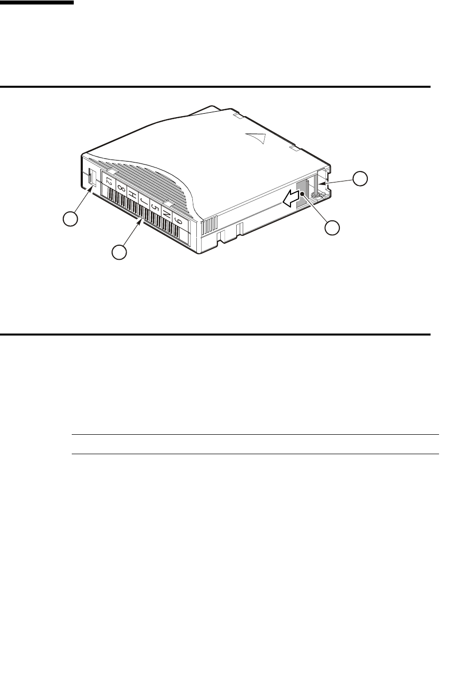
LTO (Ultrium) Cartridges
350 SL500 User’s Guide • July 2008 Revision: KA • 96116
LTO (Ultrium) Cartridges
The following sections describe LTO cartridges.
Valid Labels
LTO cartridge labels have six or eight characters (see the following note). The last two
characters are the Media ID (L1, L2, L3, L4, LT, LU and CU). The cleaning and
diagnostic label have a CLN or DG as the first characters on the label See FIGURE B-2.
Note – Unlabeled cartridges are not supported.
FIGURE B-1 LTO Cartridge Components
1. Write-protect switch (data cartridge has red switch, cleaning cartridge has gray switch)
2. Volume ID label (barcode to hub side of cartridge)
3. Access door
4. Leader pin
L204
_
019
1
2
4
3

LTO (Ultrium) Cartridges
96116 • Revision: KA Appendix B Cartridge Information 351
Discuss whether you want six or eight characters with your service representative. The
representative can set what characters are available with the “orientlabel print” and
“orientlabel” host commands from the command line interface.
TABLE B-1 LTO Cartridge Codes
Label Type of Cartridge
L1 Generation 1 data cartridge
L2 Generation 2 data cartridge
L3 Generation 3 data cartridge
L4* Generation 4 data cartridge
LT Write once read many times (WORM)—400 GB, LTO Gen 3 drive only
This feature prevents the user from altering or erasing information from
the tape. For more information, go to your vendor Web site and do a
search on WORM.
LU Write once read many times (WORM)—800 GB, LTO Gen 4 drive only
CLN plus CU Universal cleaning cartridge
Use this universal label instead of a vendor-unique label (CLN plus C1 for
Hewlett-Packard or CLN plus C2 for IBM).
DG Diagnostic cartridge (apply a DG label to a blank data cartridge to be
used for library diagnostic tests)
Note – Check availability for LTO Gen 4 drives and media. Library firmware
must be Version 1126 or later to support LTO Gen 4 drives and media.
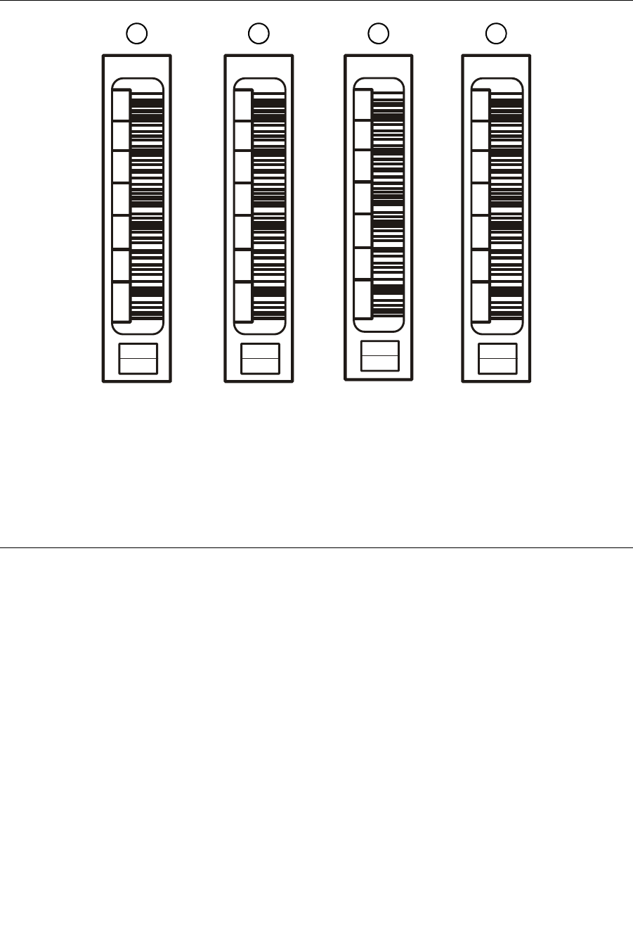
LTO (Ultrium) Cartridges
352 SL500 User’s Guide • July 2008 Revision: KA • 96116
FIGURE B-2 LTO Cartridge Labels
1. LTO Generation 2 data cartridge label.
Note: Generation 3 data cartridge labels are “L3.”; Generation 4 data cartridge labels are “L4.”
2. LTO Generation 2 Diagnostics cartridge label
3. LTO Universal cleaning cartridge label
4. LTO 400 GB Worm cartridge label (LTO Generation 3 and 4)
Note: LTO 800 GB Worm cartridge labels are “LU” and available for Generation 4 drives only.
L204
_
214
C
L
N
U
0
1
CU
9
N
5
J
H
8
L2
9
N
5
J
C
7
LT
D
G
0
0
1
L2
1234
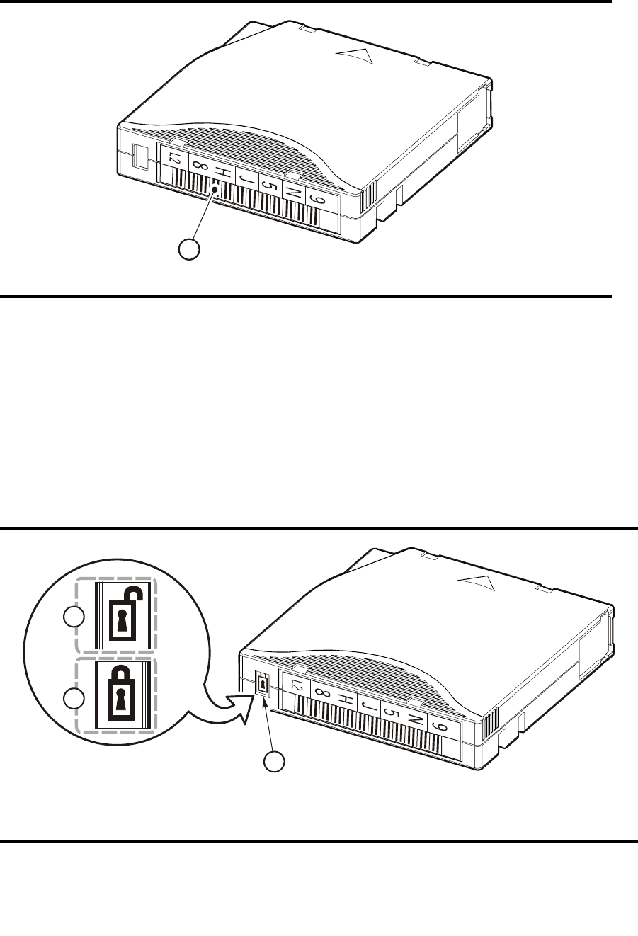
LTO (Ultrium) Cartridges
96116 • Revision: KA Appendix B Cartridge Information 353
Labels must be attached as shown in the following figure.
Write-protect Switch
You can set the write-protect switch so the cartridge is write-enabled. Slide the switch
to reveal the “open lock” symbol to write-enable the tapes. In this position, the tape
drive can write as well as read data. This setting is recommended when inserting
cartridges into the tape library.
You can set the write-protect switch so that the cartridge is read-only (nothing can be
written on the tape). Slide the switch to reveal the “closed lock” symbol. In this
position, the tape drive can only read data from the tape, but cannot write data to it.
FIGURE B-3 Apply the Utrium Cartridge Label
1. Volume number label
FIGURE B-4 Set the LTO Write-Protect Switch
1. Write-protect switch (data cartridge has red switch, cleaning cartridge has gray switch)
2. Write-enabled
L204
_
02
0
111
1
3
2
L204
_
021
1

LTO (Ultrium) Cartridges
354 SL500 User’s Guide • July 2008 Revision: KA • 96116
3. Write-protected
FIGURE B-4 Set the LTO Write-Protect Switch
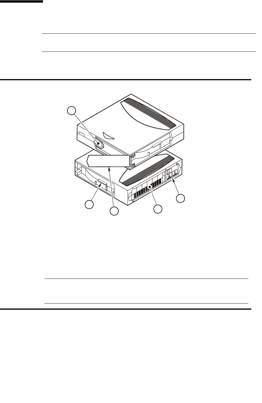
SDLT/DLT-S4 Cartridges
96116 • Revision: KA Appendix B Cartridge Information 355
SDLT/DLT-S4 Cartridges
Note – Your robotics unit must be part number 314558705 or higher to read SDLT
cartridge labels.
The following sections describe SDLT/DLT-S4 cartridges.
For best results:
■Use Super DLTtape 1 cartridges in SDLT 320 tape drives
■Use Super DLTtape 2 cartridges in SDLT 600 tape drives
■Use DLTtape S4 cartridges in DLT-S4 tape drives
FIGURE B-5 SDLT Cartridge Components
1. Tape leader
2. SDLT cartridge identifier tab
3. Access door
4. Volume serial number (VOLID) label
5. Read/Write protect switch
Note – DLTtape S4 cartridges are black in color. See Quantum manuals for more
information regarding DLTtape S4 cartridges.
Library firmware must be version 1126 or later for DLT-S4 support.
L204_564
1
2
34
5
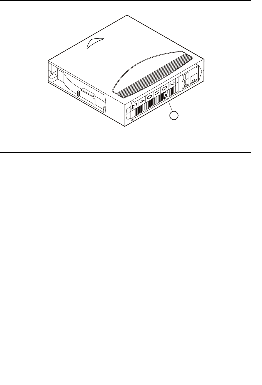
SDLT/DLT-S4 Cartridges
356 SL500 User’s Guide • July 2008 Revision: KA • 96116
Labels must be attached as shown in the following figure.
Valid Labels
SDLT/DLT-S4 cartridge labels have six, seven, or eight characters (see the following
note). The last character is the media ID (S, 2 or 4). CLN or DG are the first characters
on the cleaning or diagnostic label.
FIGURE B-6 Apply the SDLT Cartridge Label
1. Volume number label
Note: Consult Quantum documentation regarding application of labels for DLTtape S4 tapes.
L204_565
1
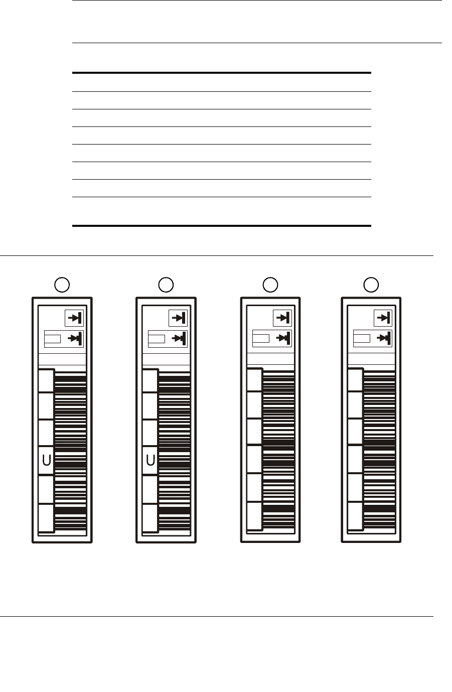
SDLT/DLT-S4 Cartridges
96116 • Revision: KA Appendix B Cartridge Information 357
Note – Discuss whether you want six or seven characters with your service
representative. The representative can set what characters are available with the
“orientlabel print” and “orientlabel” host commands from the command line interface.
TABLE 0-1 SDLT/DLT-S4 Cartridge Codes
Label Type of Cartridge
S SDLT 220/320 data cartridge
2 SDLT 600 data cartridges
4 DLTtape S4 data cartridges
CLN + S SDLT cleaning cartridge.
DG + 2 Diagnostic cartridge—SDLT
DG + 4 Diagnostic cartridge—DLT-S4
Note: Apply a DG label to a blank data cartridge to be used for
library diagnostic tests.
FIGURE B-7 SDLT Cartridge Labels
1. SDLT 320 data label
2. SDLT 600 data label
Note: DLT-S4 data cartridges contain the number “4.”
C
L
0
0
1
S
N
D
G
0
0
1
2
8
2
6
2
C
2
8
2
6
2
C
S
L204
_
567
1234
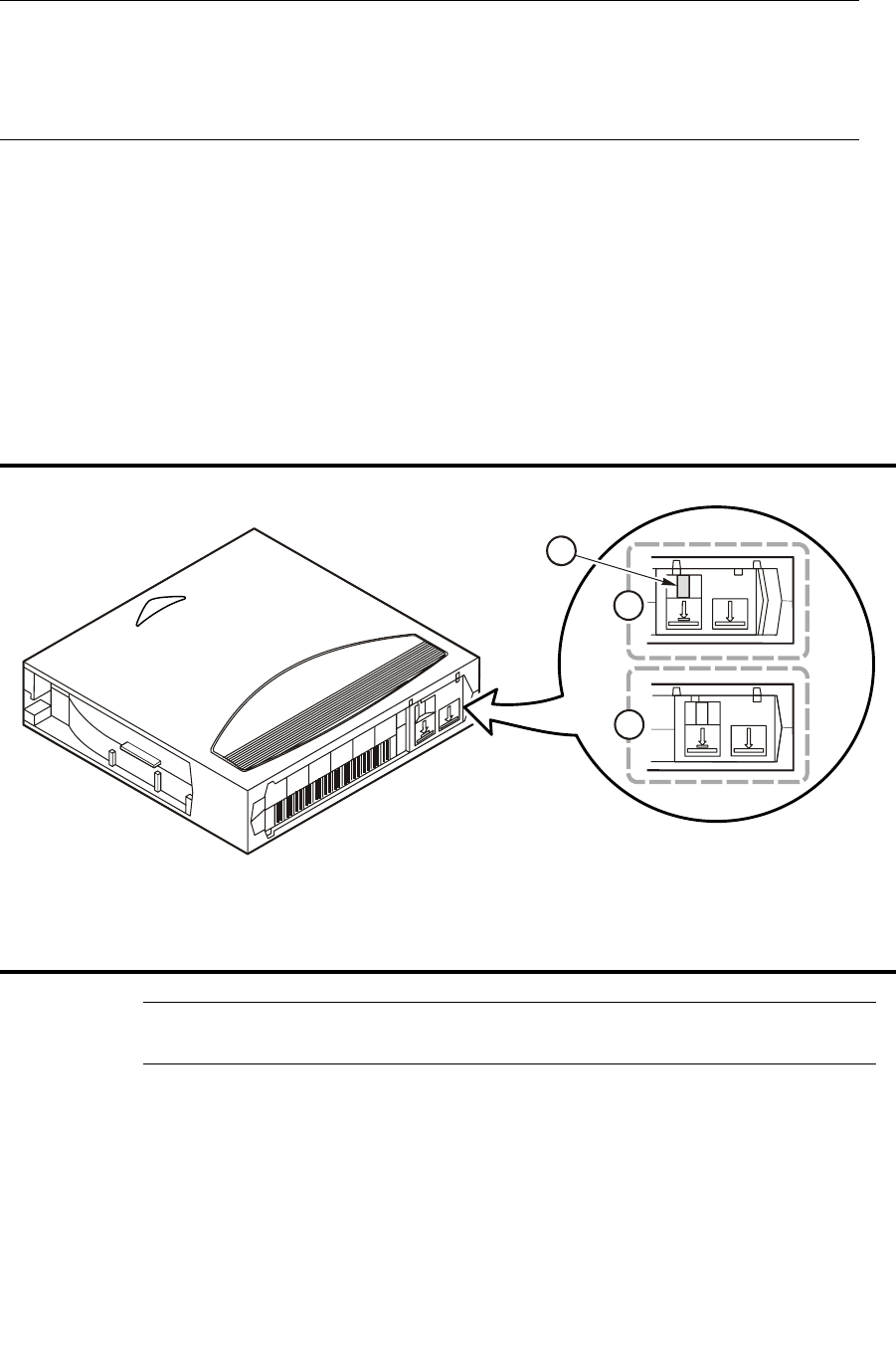
SDLT/DLT-S4 Cartridges
358 SL500 User’s Guide • July 2008 Revision: KA • 96116
Write-Protect Switch
You can set the write-protect switch so the cartridge is write-enabled. Slide the switch
to reveal the orange indicator to write-enable the tapes. In this position, the tape drive
can write as well as read data. This setting is recommended when inserting cartridges
into the tape library.
You can set the write-protect switch so that the cartridge is read-only (nothing can be
written on the tape). Slide the switch to reveal the “closed lock” symbol. In this
position, the tape drive can only read data from the tape, but cannot write data to it.
Note – See Quantum documentation regarding the write-protect/write enable setting
for DLTtape S4 tapes.
3. SDLT 320/600 diagnostic label
Note: DLT-S4 diagnostic cartridge labels are “DG + 4.”
4. SDLT 320/600 cleaning label
Note: You may use SDLT “CLN + S” cleaning labels for DLT-S4 drives.
FIGURE B-8 Set the SDLT Write-Protect Switch
1. Write-protect switch (data cartridge has orange indicator)
2. Write-protected position
3. Write-enabled position
FIGURE B-7 SDLT Cartridge Labels
L204_566
1
3
2


Cartridge Handling Tasks
360 SL500 User’s Guide • July 2008 Revision: KA • 96116
▼ Apply a Label to a Cartridge
Cartridge labels reflect the cartridge media and usage. If your cartridges were not
ordered with labels already applied, you must apply them yourself. You must correctly
label all cartridges for library use.
Caution – Possible misread of volume number label: Make sure the edges of the labels do
not curl; curling causes the cartridges to stick in the tape drive loader and the robot to
misread the label.
Use the procedure to apply a label to a tape cartridge.
1. Make sure the cartridge has been at room temperature for at least 24 hours.
2. Clean the surface where the labels will be placed using a cleaning solution made for
this purpose see “Maintaining Cartridges” on page 348.
3. Locate the type of label that you require.
4. Hold the cartridge so that the write-protect switch is toward you.
5. Attach the label to the cartridge. See the following figures for details:
■LTO cartridges—FIGURE B-3 on page 353
■SDLT/DLT-S4 cartridges—FIGURE B-6 on page 356

96116 • Revision: KA 361
APPENDIX C
Web-launched SL Console Server
The Web-launched SL Console is a standard feature of the SL500 and is included on a
CD shipped with each library. It enables the SL Console to be installed on a centralized
Web server. Individual clients can then use a supported Web browser to download and
log in to the Web-launched SL Console.
The Web-launched SL Console is deployed as a Java WebARchive (.war) file.
Security Considerations
The customer is responsible for implementing all appropriate security systems,
including firewalls, user access, etc.
Server Requirements
You can deploy the Web-launched SL Console on any Web server that is compliant
with the J2EE (Java 2 Platform, Enterprise Edition) platform. It is recommended that
you use the Java System Web Server.
Note – All procedures in this document assume you are using the Java System Web
Server.
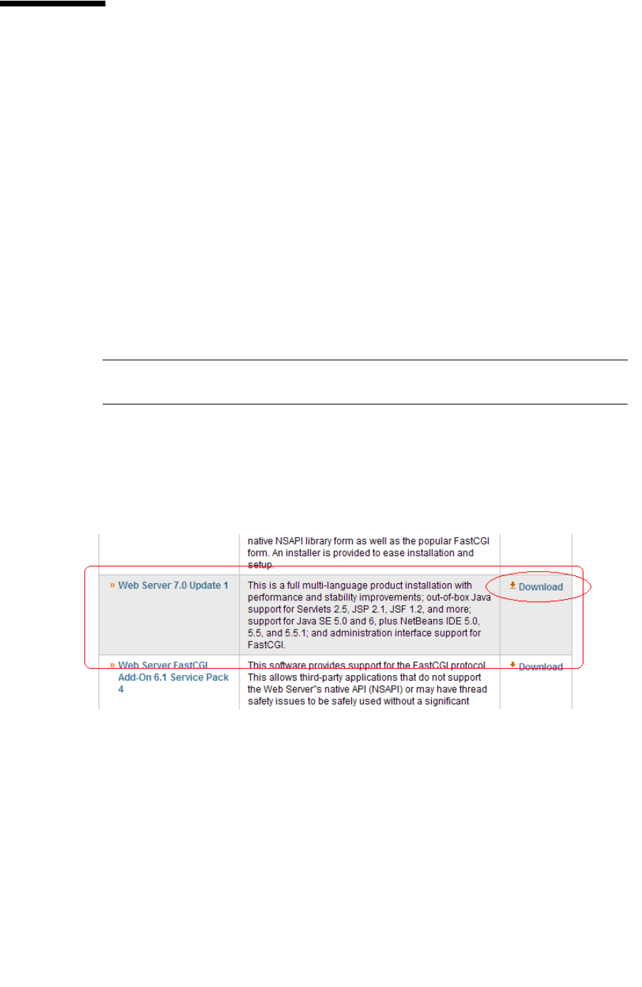
Server Installation and Management
362 SL500 User’s Guide • July 2008 Revision: KA • 96116
Server Installation and Management
Installation and management of the Web-launched SL Console server involves the
following procedures:
■“Download the Java System Web Server” on page 362
■“Install the Sun Java System Web Server” on page 366
■“Log in to the Java System Web Server Administration Console” on page 370
■“Install and Deploy the Web-launched SL Console” on page 373
■“Start the Web-launched SL Console” on page 379
■“Update the Web-launched SL Console” on page 381
▼ Download the Java System Web Server
Use this procedure to download the Java System Web Server, if it is not already
installed on your server.
Note – This procedure requires you to have a Sun Online Account username and
password.
1. Open a Web browser, and in the Location Bar or Address field enter the URL of the
Sun Web Servers page:
http://www.sun.com/download/index.jsp?cat=Web%20%26%20Proxy%20Servers&tab=3&subcat=Web%20Servers
2. On the Web Servers page, click the Web Server link that corresponds to your server
platform.
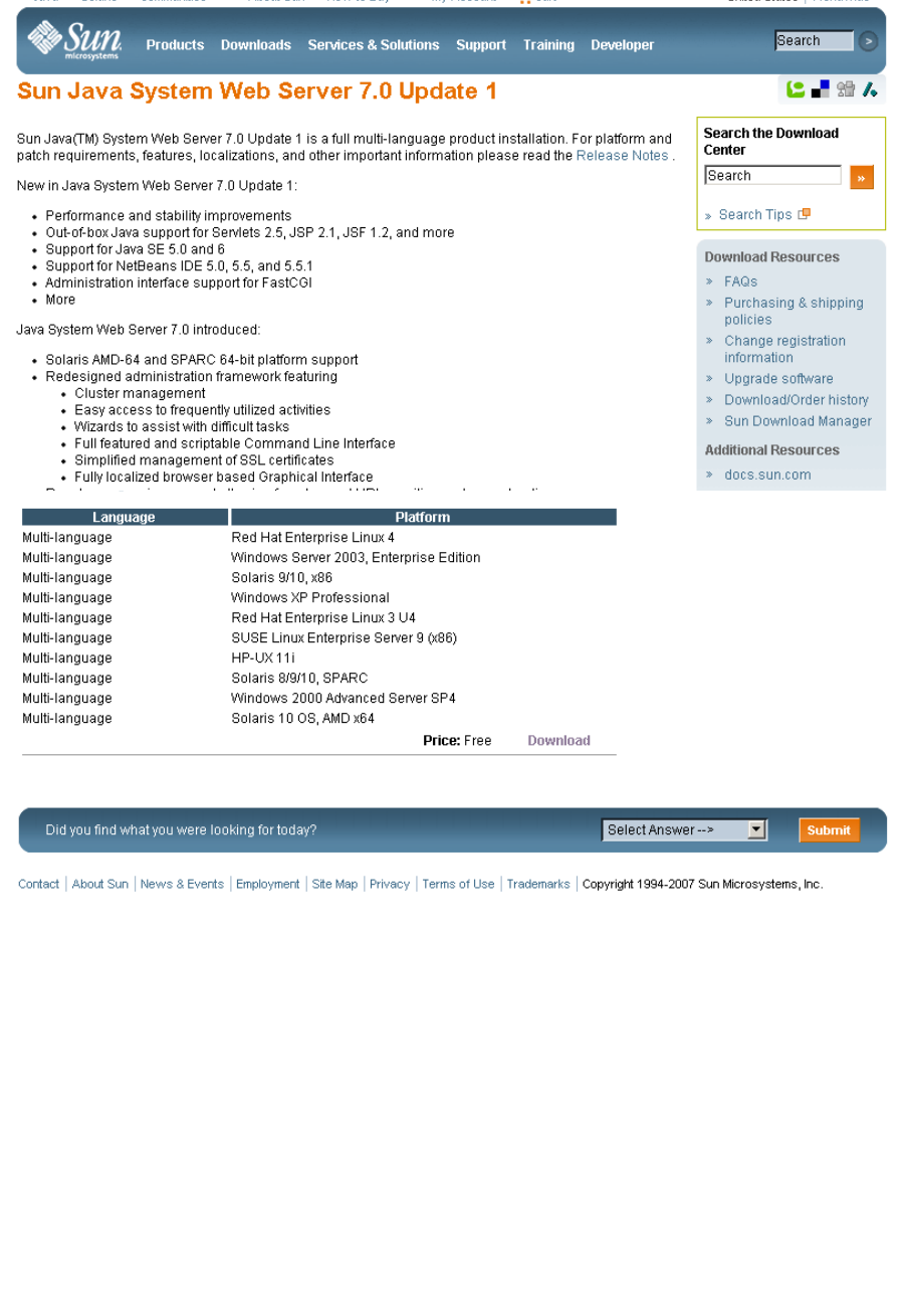
Server Installation and Management
96116 • Revision: KA Appendix C Web-launched SL Console Server 363
3. On the Sun Java System Web Server screen (this will vary according to your selection
in the previous step), scroll down to verify the list of supported platforms, and click
Download.
4. In the Sun Download Center Login screen, enter your Username and Password, and
click Login.
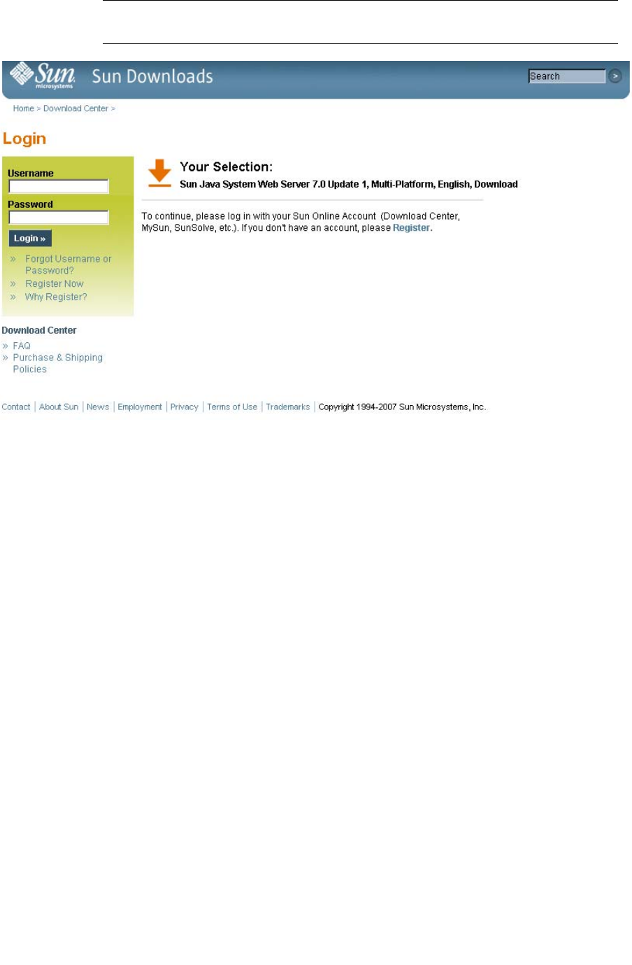
Server Installation and Management
364 SL500 User’s Guide • July 2008 Revision: KA • 96116
Note – If you do not already have an account, click Register Now and follow the
instructions to create one.
5. In the Sun Download Center screen, make the following selections:
■Click the Accept License Agreement radio button.
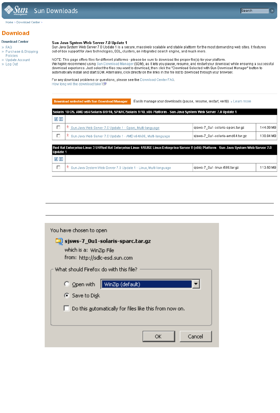
Server Installation and Management
96116 • Revision: KA Appendix C Web-launched SL Console Server 365
■Click the Sun Java System Web Server link that corresponds to your server
platform.
6. In the popup, click Save to Disk, to save the compressed archive file to a directory of
your choice, and click OK.
Note – This process may take several minutes.
7. Use the appropriate extraction utility (for example, gunzip, pkunzip) to extract the
Sun Java System Web Server files to a directory of your choice.
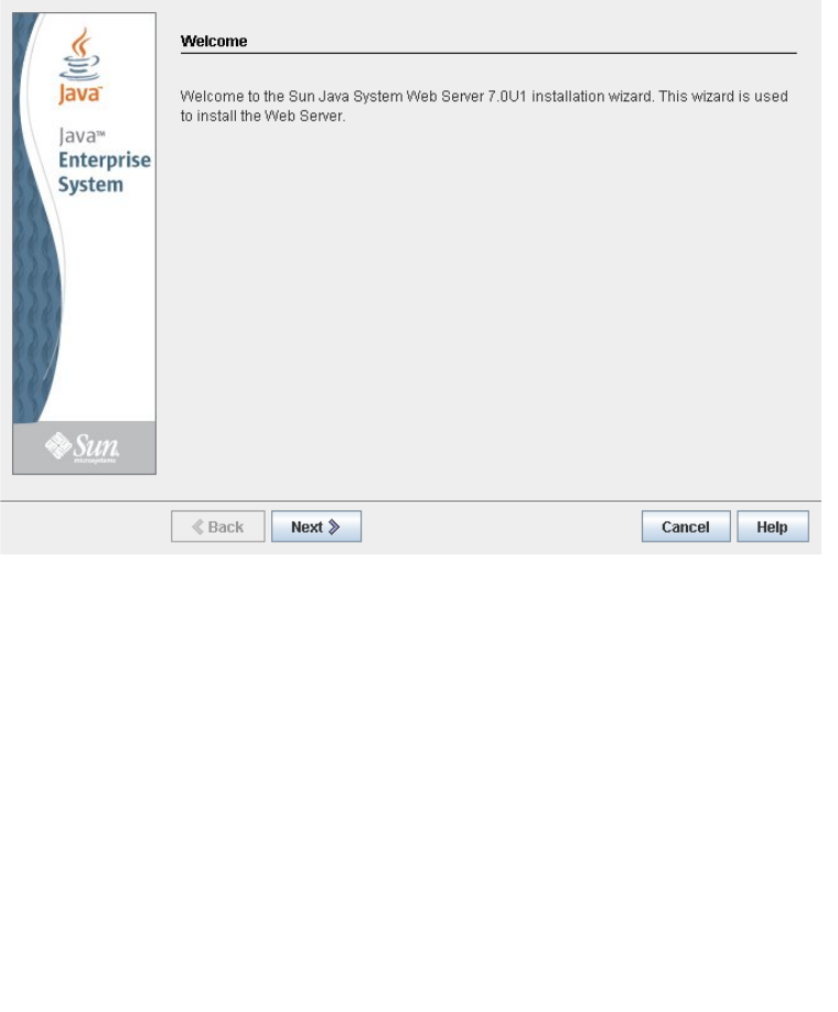
Server Installation and Management
366 SL500 User’s Guide • July 2008 Revision: KA • 96116
▼ Install the Sun Java System Web Server
Use this procedure to install the Java System Web Server, if it is not already installed on
your server.
1. In the directory where you have extracted the Sun Java System Web Server files,
double-click or execute from a command line the setup file (setup or setup.exe,
depending on your platform).
If you are installing on a Solaris platform, you may need to invoke root or sudo
permissions, depending on the directory you are installing to. If so, use the following
steps:
a. cd extraction_directory
where extraction_directory is the directory to which you extracted the compressed
Java Web Server files.
b. xhost +
c. sudo ./setup
2. On the Welcome screen, click Next.
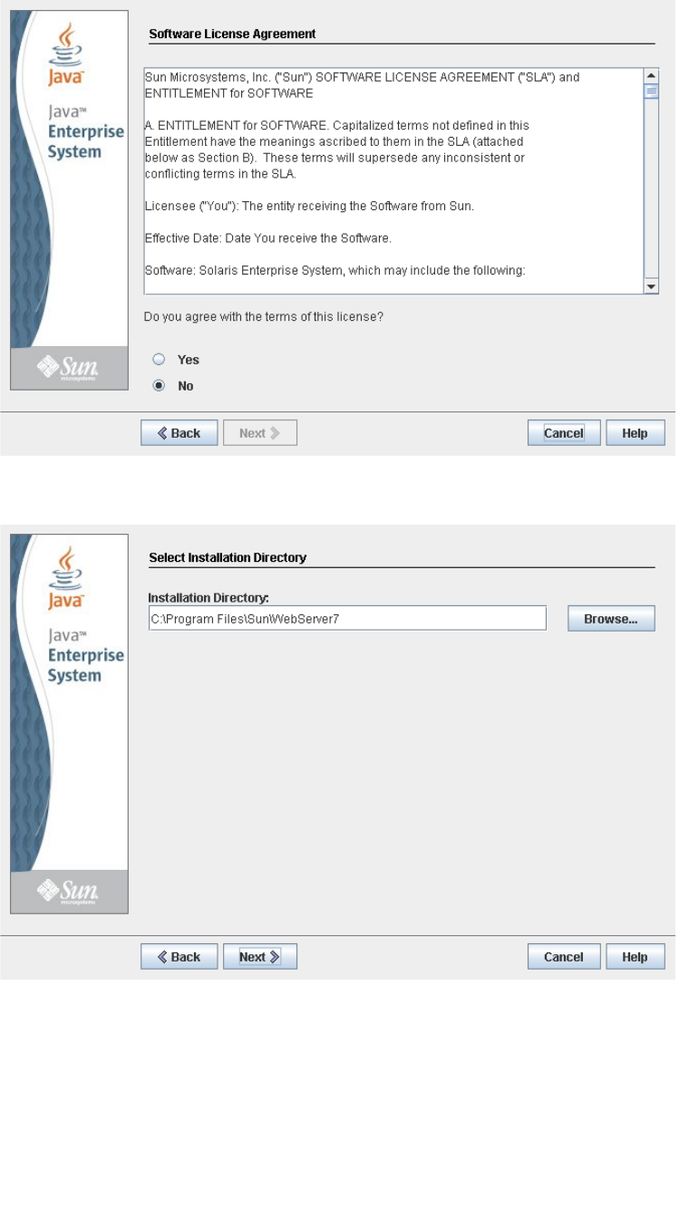
Server Installation and Management
96116 • Revision: KA Appendix C Web-launched SL Console Server 367
3. On the Software License Agreement screen, click the Yes radio button, and click
Next.
4. On the Select Installation Directory screen, specify the directory where you want the
Web Server installed, and click Next.
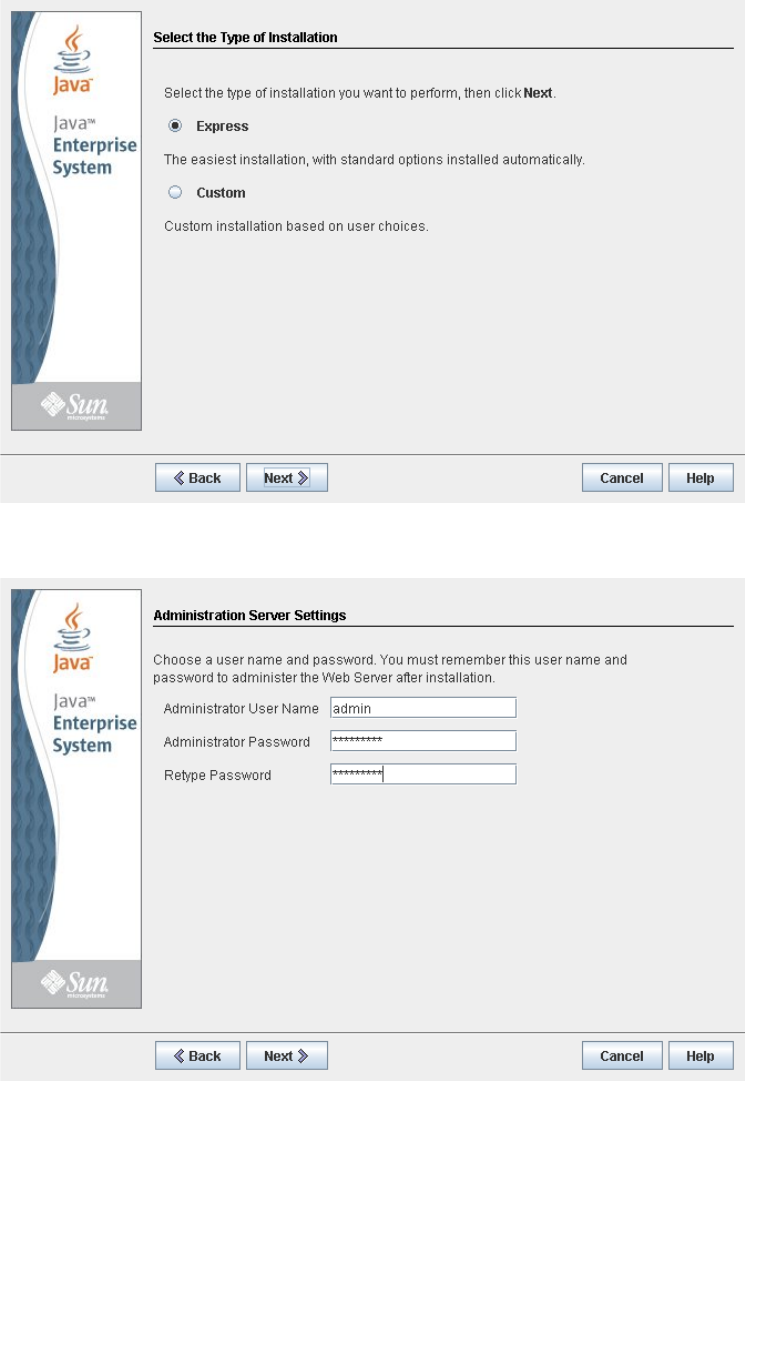
Server Installation and Management
368 SL500 User’s Guide • July 2008 Revision: KA • 96116
5. On the Type of Installation screen, click Express, and click Next.
6. On the Administration Server Settings screen, specify a secure password for the
admin user, and click Next.
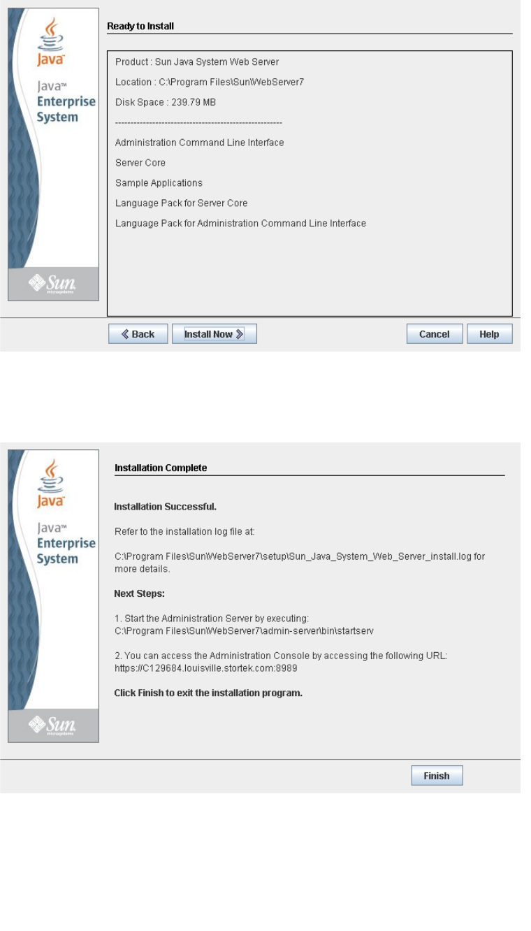
Server Installation and Management
96116 • Revision: KA Appendix C Web-launched SL Console Server 369
7. On the Ready to Install screen, review the installation information and click Install
Now.
The installation begins, and screen with a progress bar is displayed.
8. On the Installation Complete screen, review the information and write down the
Administration Console URL specified in #2 under “Next Steps. You will need this
in the next procedure.
9. Click Finish to exit the setup program.
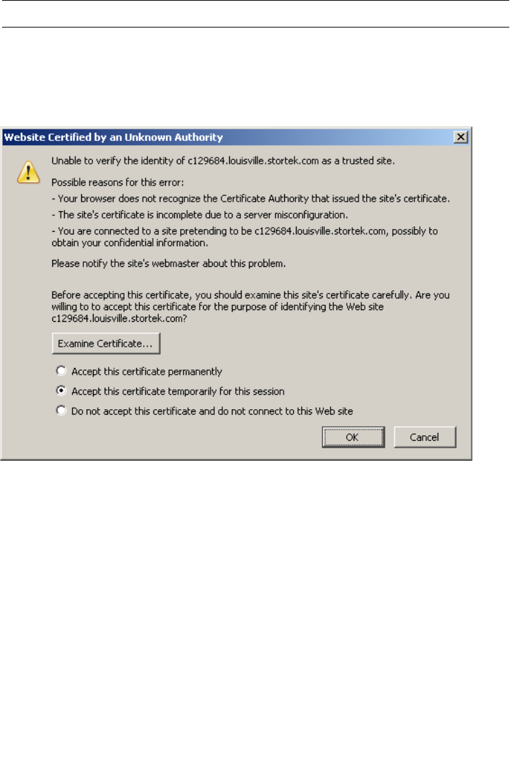
Server Installation and Management
370 SL500 User’s Guide • July 2008 Revision: KA • 96116
▼ Log in to the Java System Web Server
Administration Console
1. Start the Sun Java System Web Server, if it is not already running:
■On Windows—Click Start > All Programs > Sun Microsystems >Web Server 7.0 >
Start Administration Server.
■On Solaris—Open a terminal window, and type the following:
sudo /opt/webserver7/admin-server/bin/startserv
Note – Wait several minutes for the server to start.
2. Open a Web browser, and in the Location Bar or Address field enter the URL you
wrote down at the end of the previous procedure (“Install the Sun Java System Web
Server”). This will start the Admin Console.
3. In the popup, accept the server certificate, and click OK.
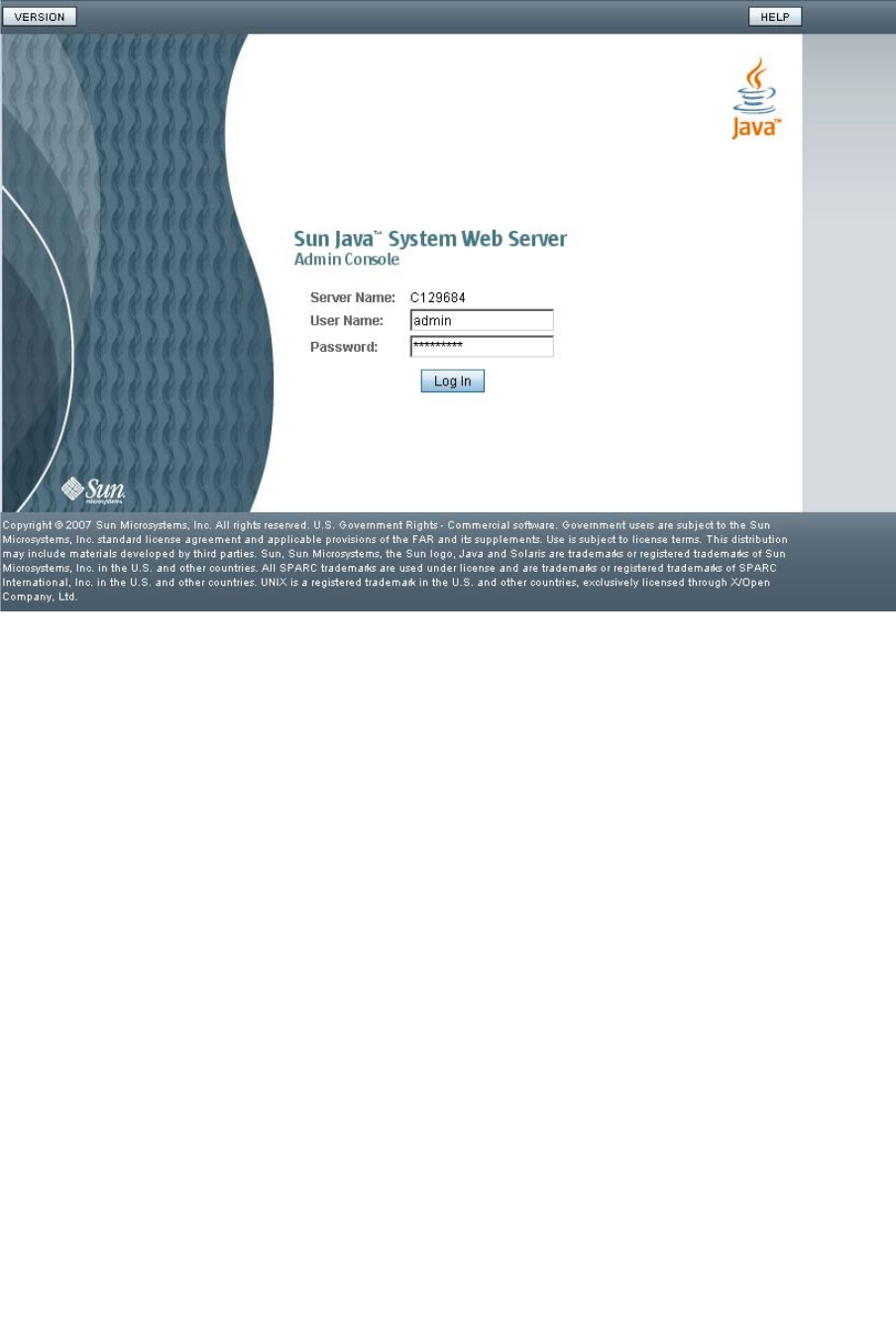
Server Installation and Management
96116 • Revision: KA Appendix C Web-launched SL Console Server 371
4. In the Web browser where you opened the Admin Console URL, enter the admin
User Name and Password, and click Log in.
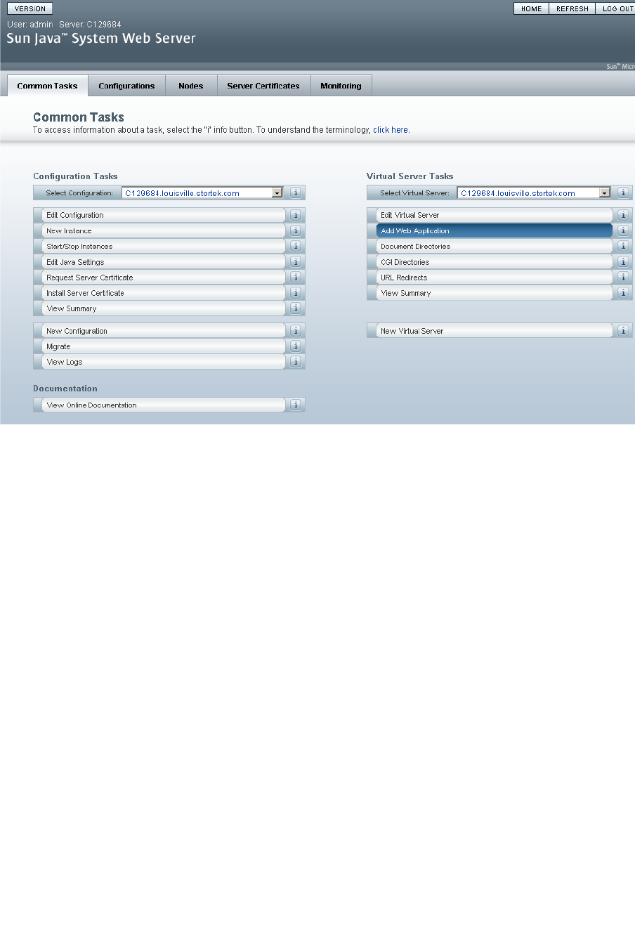
Server Installation and Management
372 SL500 User’s Guide • July 2008 Revision: KA • 96116
5. The Common Tasks screen appears.
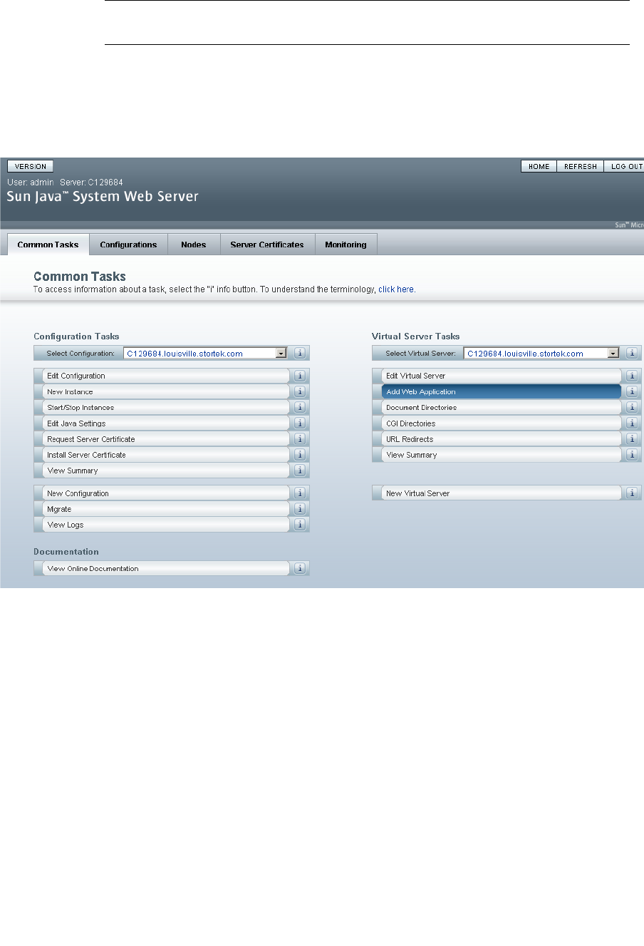
Server Installation and Management
96116 • Revision: KA Appendix C Web-launched SL Console Server 373
▼ Install and Deploy the Web-launched SL Console
Note – Before you perform this activity, you must obtain the Web-launched
SL Console installation CD.
1. On the server, insert the Web-launched SL Console installation CD in the CD drive.
2. Log in to the Sun Java System Web Server administration console. See “Log in to the
Java System Web Server Administration Console” on page 370 for details.
3. On the Common Tasks screen, click Add Web Application.
4. On the Add Web Application screen, make the following entries:
■Web Application Location: Click the Browse button and browse to the location of
the opel.war file on the installation CD.
■URI: Type /opel
■Leave all other fields as the defaults.
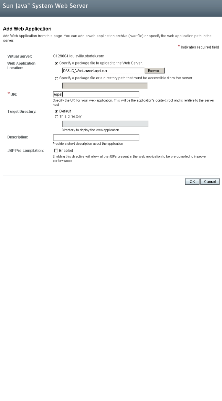
Server Installation and Management
374 SL500 User’s Guide • July 2008 Revision: KA • 96116
■Click OK.
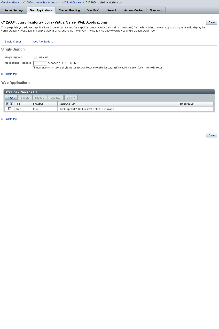
Server Installation and Management
96116 • Revision: KA Appendix C Web-launched SL Console Server 375
5. On the Web Applications screen, click Save.
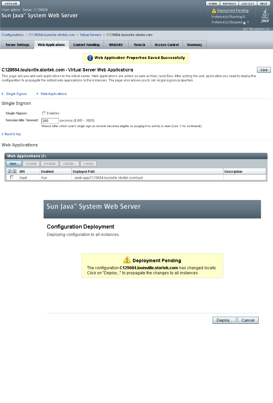
Server Installation and Management
376 SL500 User’s Guide • July 2008 Revision: KA • 96116
6. On the updated Web Applications screen, click the Deployment Pending link in the
upper-right corner.
7. On the Configuration Deployment screen, click Deploy.
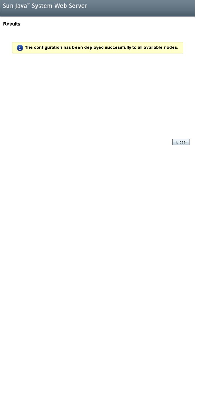
Server Installation and Management
96116 • Revision: KA Appendix C Web-launched SL Console Server 377
8. On the Results screen, click Close.
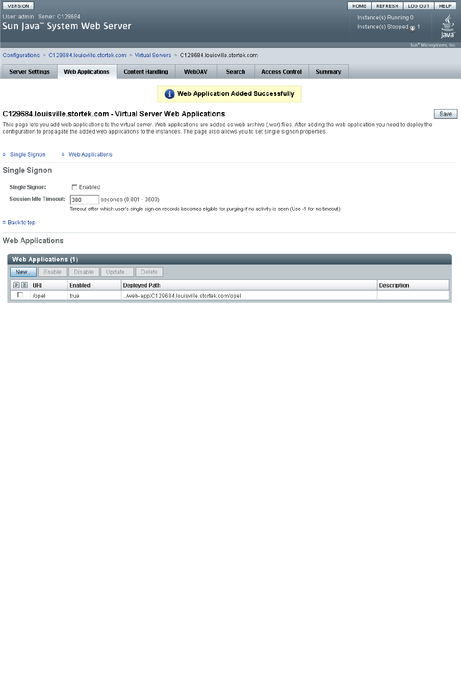
Server Installation and Management
378 SL500 User’s Guide • July 2008 Revision: KA • 96116
9. The Web Applications screen displays a message that the application has been added
successfully.
You can click the Home button in the upper-right corner to return to the Common
Tasks screen.
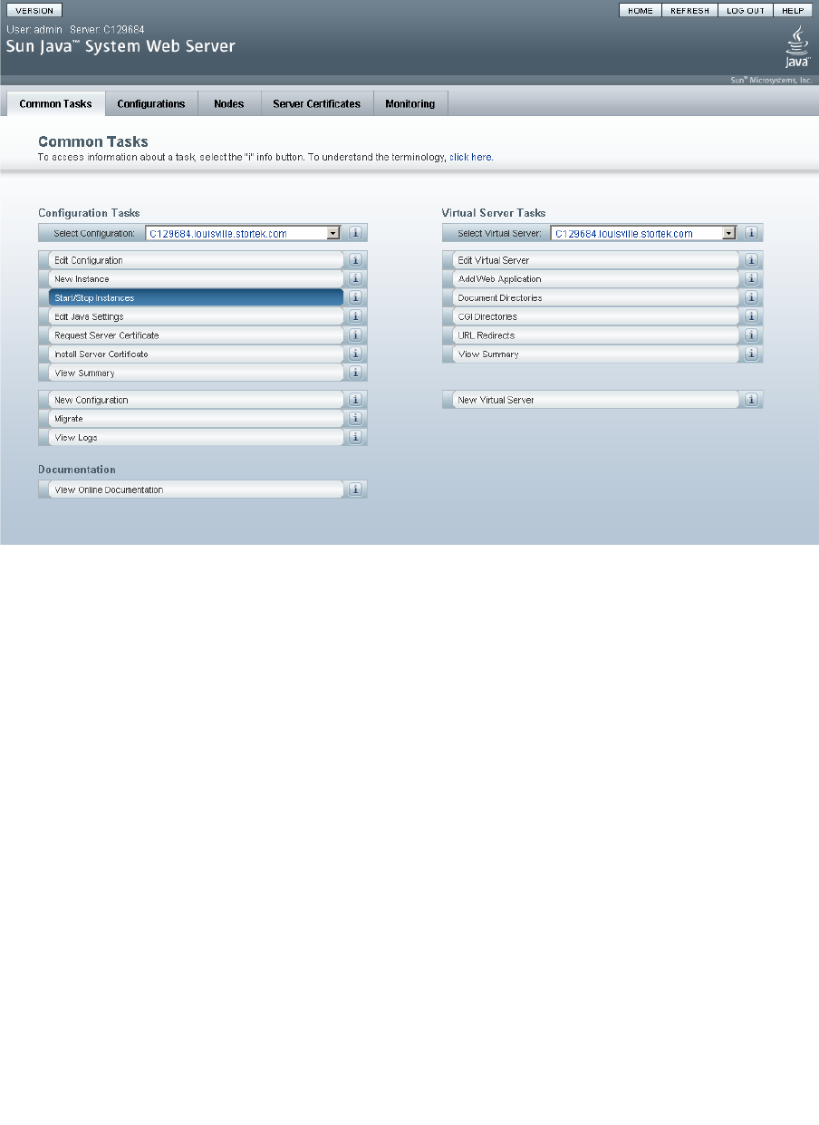
Server Installation and Management
96116 • Revision: KA Appendix C Web-launched SL Console Server 379
▼ Start the Web-launched SL Console
1. Log in to the Sun Java System Web Server administration console. See “Log in to the
Java System Web Server Administration Console” on page 370 for details.
2. On the Common Tasks screen, click Start/Stop Instances.
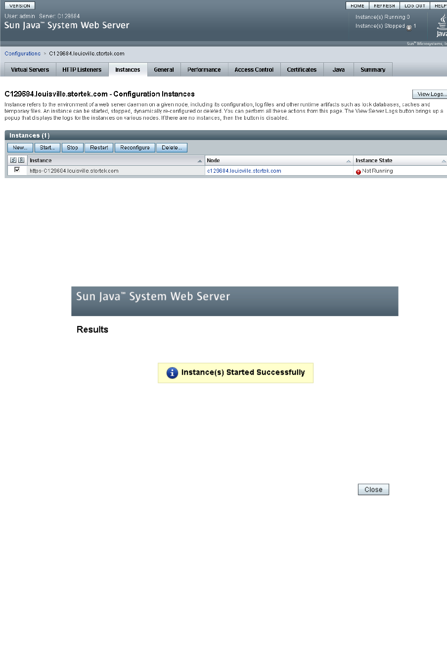
Server Installation and Management
380 SL500 User’s Guide • July 2008 Revision: KA • 96116
3. On the Configuration Instances screen, click the checkbox next to the local instance
of the Web-launched SL Console server, and click Start.
The Web-launched SL Console application instances are started, and screen with a
progress bar is displayed.
4. On the Results screen, click Close.
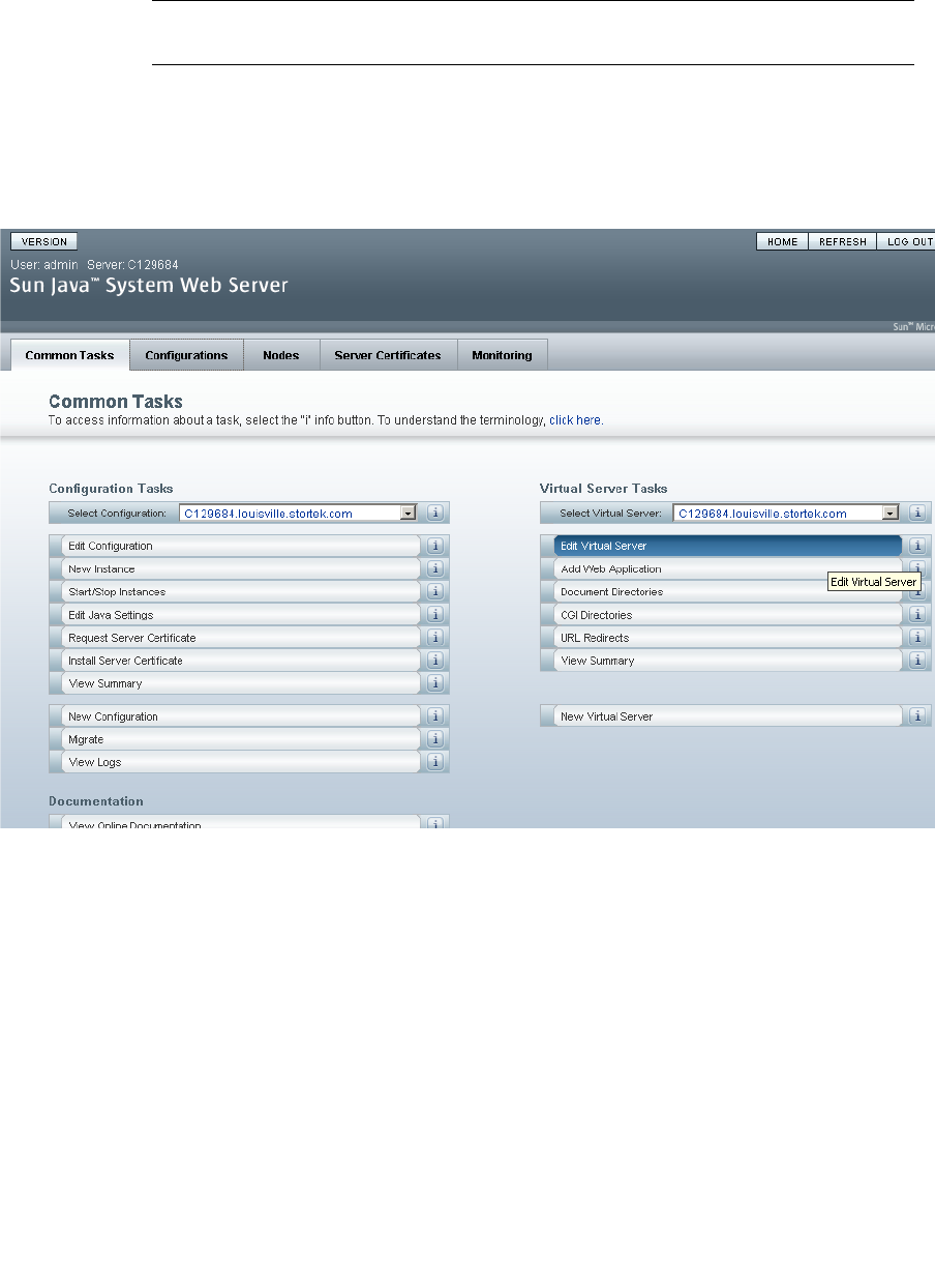
Server Installation and Management
96116 • Revision: KA Appendix C Web-launched SL Console Server 381
▼ Update the Web-launched SL Console
You can update the Web-launched SL Console while it is running. Updates are
automatically propagated to the clients when they retrieve the Web-launched
SL Console application from the server.
Note – Before you perform this activity, you must obtain the Web-launched
SL Console update CD.
1. On the server, insert the Web-launched SL Console update CD in the CD drive.
2. Log in to the Sun Java System Web Server administration console. See “Log in to the
Java System Web Server Administration Console” on page 370 for details.
3. On the Common Tasks screen, click Edit Virtual Server.
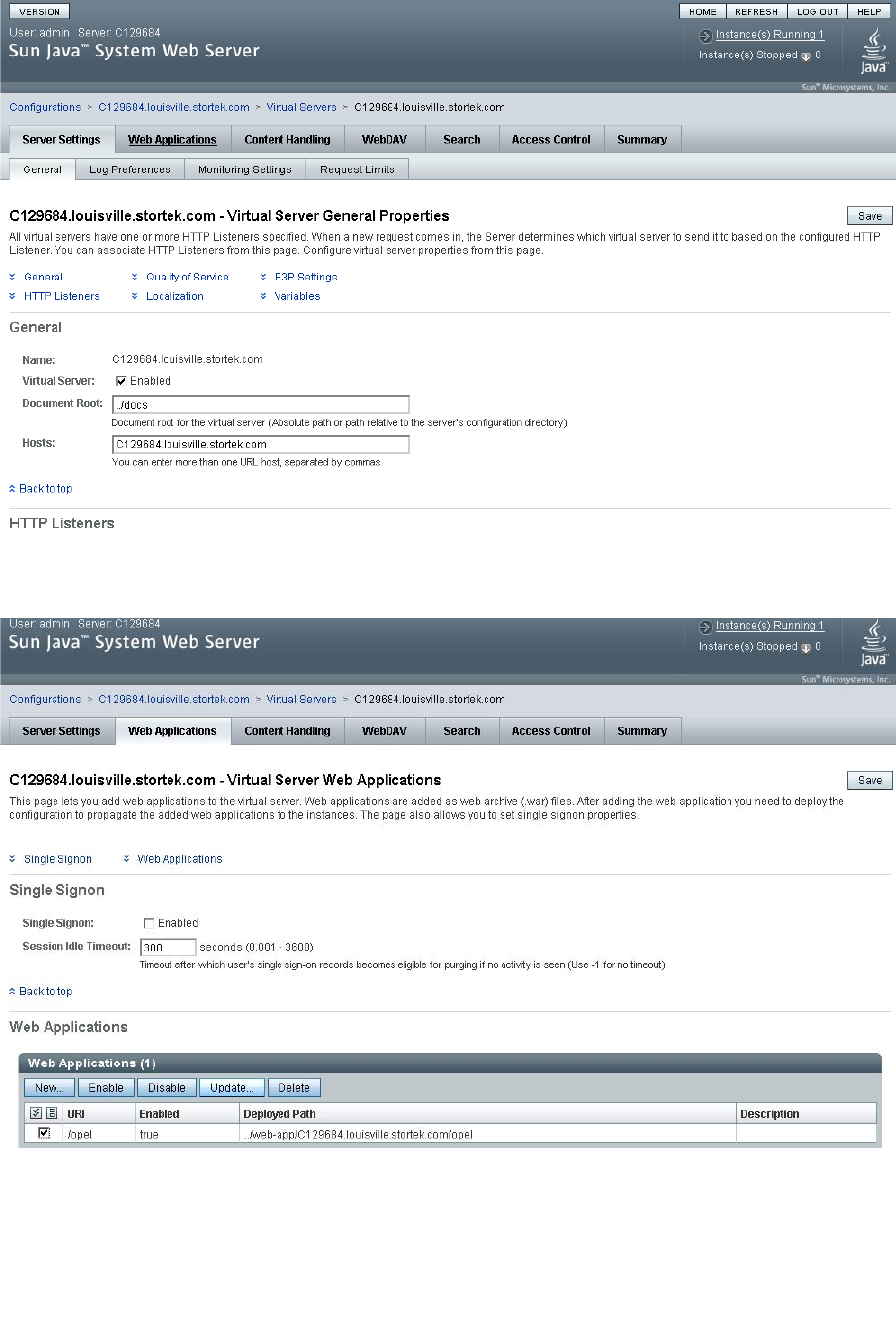
Server Installation and Management
382 SL500 User’s Guide • July 2008 Revision: KA • 96116
4. On the General Properties screen, click the Web Applications tab.
5. On the Web Applications screen, click the checkbox next to the /opel URI, and click
Update.
6. On the Update Web Application screen, make the following entries:
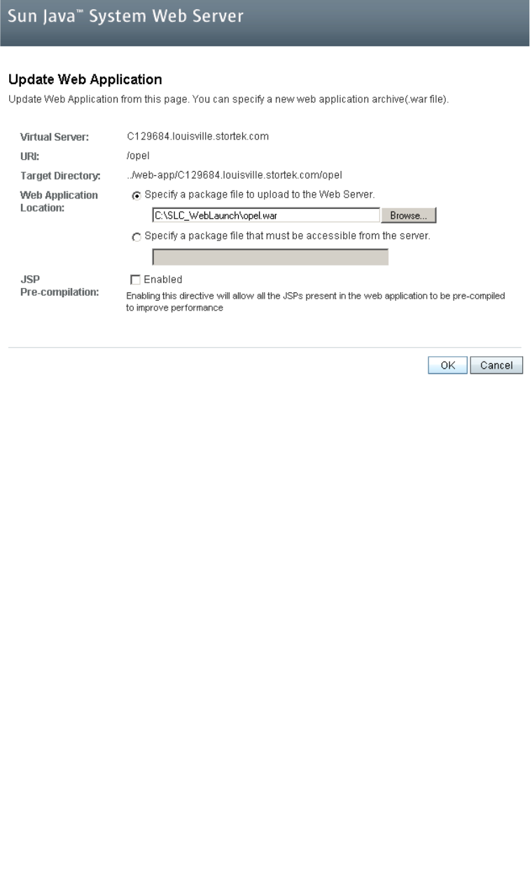
Server Installation and Management
96116 • Revision: KA Appendix C Web-launched SL Console Server 383
■Web Application Location: Click the Browse button and browse to the location of
the opel.war file on the update CD.
■Leave all other fields as the defaults.
■Click OK.
The server update begins, and screen with a progress bar is displayed.
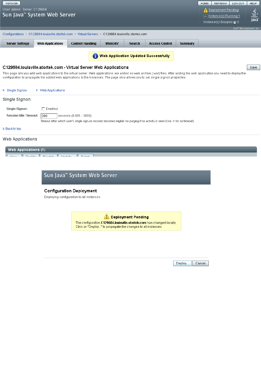
Server Installation and Management
384 SL500 User’s Guide • July 2008 Revision: KA • 96116
7. On the Web Applications screen, click the Deployment Pending link in the upper
right corner.
8. On the Configuration Deployment screen, click Deploy.
The deployment begins, and screen with a progress bar is displayed.
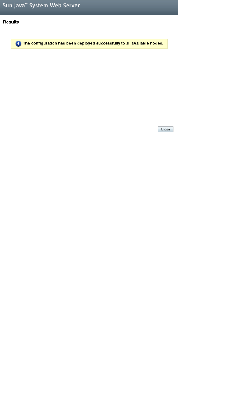
Server Installation and Management
96116 • Revision: KA Appendix C Web-launched SL Console Server 385
9. In the Results screen, click Close to return to the Web Applications screen.
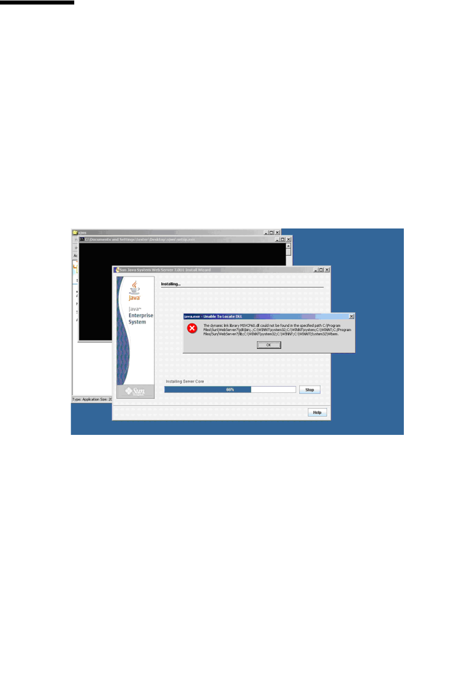
Common Problems and Solutions
386 SL500 User’s Guide • July 2008 Revision: KA • 96116
Common Problems and Solutions
This section describes solutions to some common problems with the installation and
maintenance of the Java System Web Server.
Windows 2000 Sun Java System Web Server
Installation Errors
Windows MSVCP60.dll Error
If you are installing on a Windows 2000 platform that does not include the Microsoft
Visual C v6 runtime DLL, MSVCP60.dll, during installation you will see errors similar
to the following:
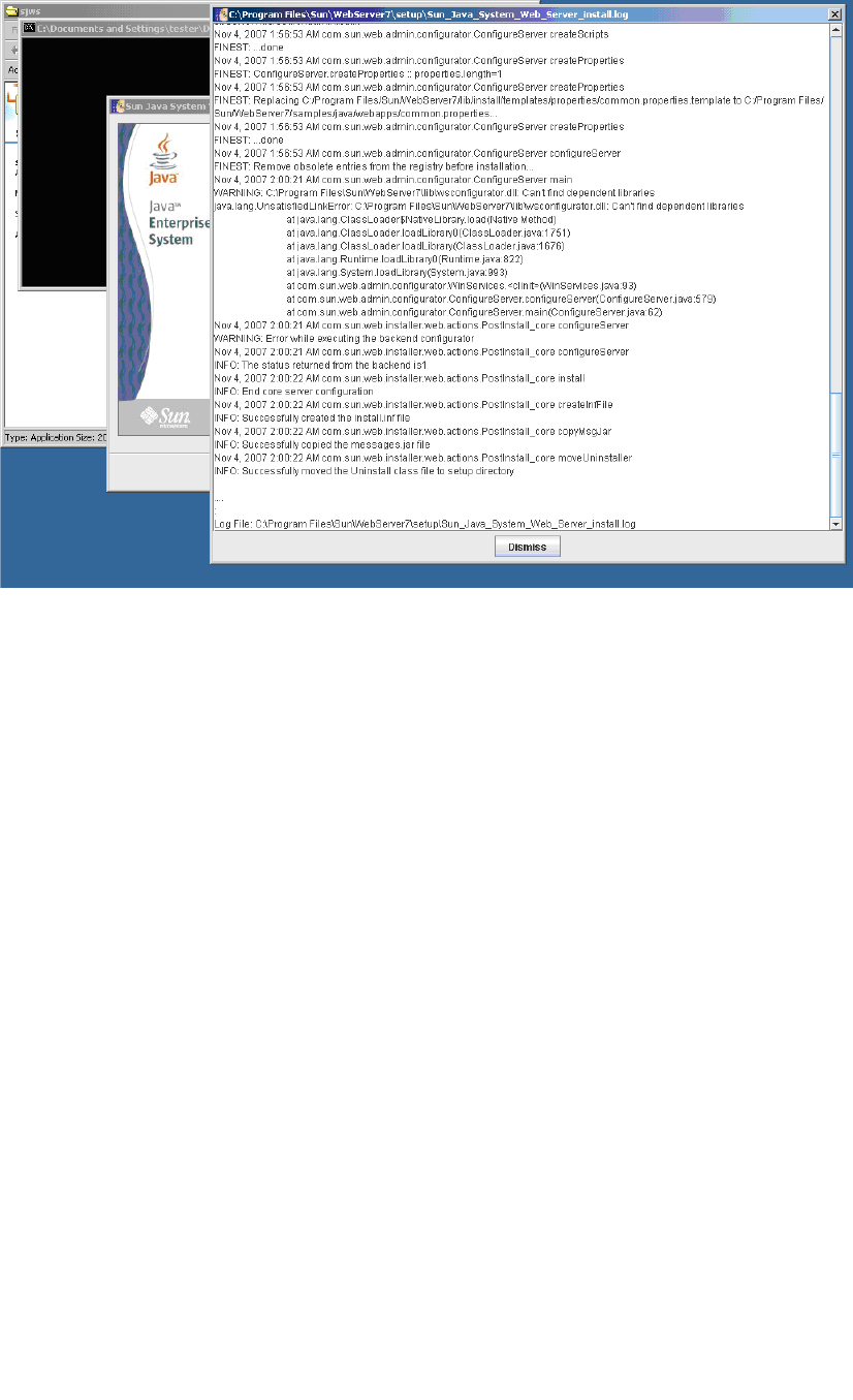
Common Problems and Solutions
96116 • Revision: KA Appendix C Web-launched SL Console Server 387
The Web server installation log will include errors similar to the following:
▼ Remedy for Windows MSVCP60.dll Error
Use this procedure to solve the Windows MSVCP60.dll error.
1. Perform a Web search for the following string:
msvcp60.dll download
2. Download the DLL file to the /winnt/system32 directory.
3. Delete the directory where you partially installed the Java System Web Server on the
failed installation.
4. Repeat the Java System Web Server installation from the beginning.
The installation should complete successfully with no recurrence of the error.
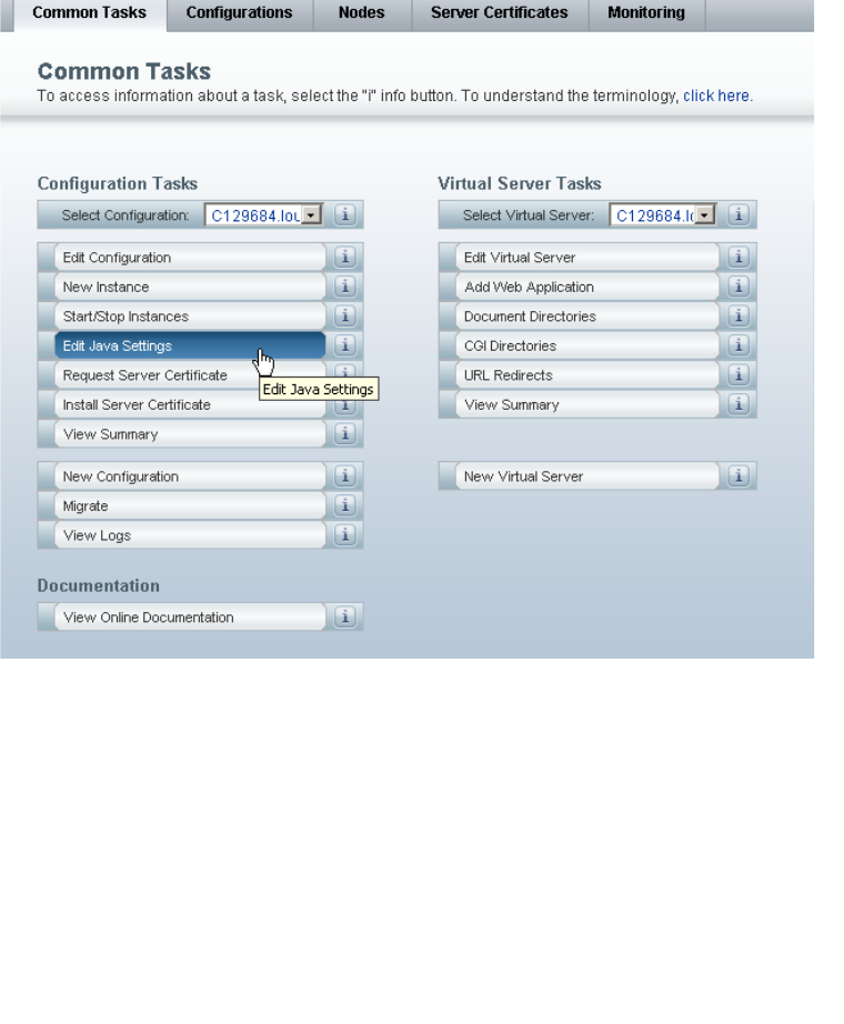
Common Problems and Solutions
388 SL500 User’s Guide • July 2008 Revision: KA • 96116
▼ Solaris 9 & 10 Sun Java System Web Server
Installation Errors
Java Home Error
If you cannot start the server instance and you see errors claiming your HotSpot start
failed and your JVM could not be found, you need to change the Java Home
configuration of your Sun Java System Web Server.
▼ Remedy for Solaris Java Home Error
Use this procedure to solve the Java Home error.
1. Log in to the Sun Java System Web Server administration console. See “Log in to the
Java System Web Server Administration Console” on page 370 for details.
2. Select Home > Common Tasks.
3. Under Configuration Tasks, click Edit Java Settings.
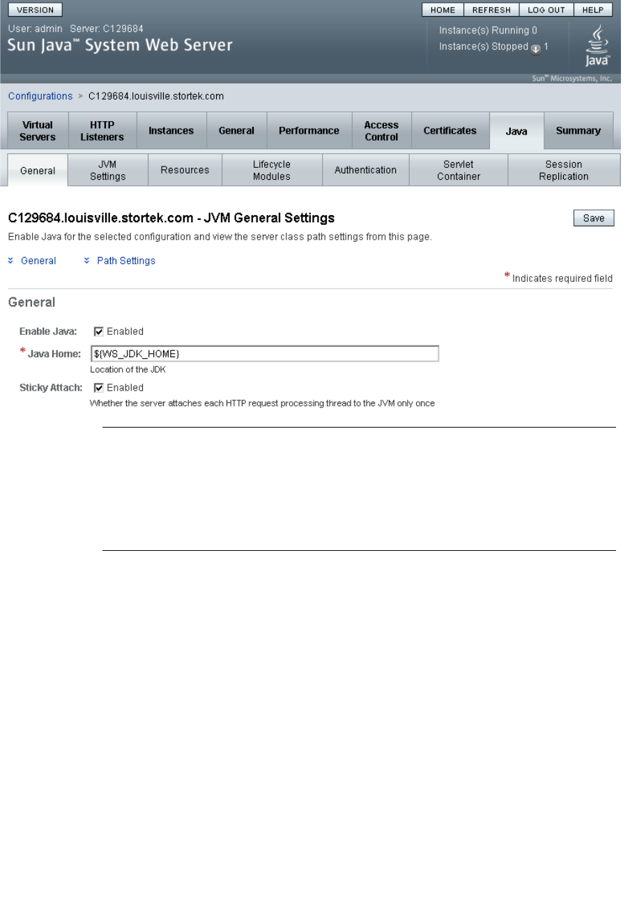
Common Problems and Solutions
96116 • Revision: KA Appendix C Web-launched SL Console Server 389
4. In Java Home, enter the directory where your JDK/JRE is installed. For example:
/usr/java
Note – You may also need to change permissions on the top-level directory where you
installed the Sun Java System Web Server. In order for a non-root user to start a server
instance, the user must be able to write to the server directory. For example, if you
installed the server to the top-level directory /opt/webserver7, the user starting the
server instance must be able to write to this directory and the https-server_name
directory beneath it. For additional information see the Sun Java System Web Server
site.

Common Problems and Solutions
390 SL500 User’s Guide • July 2008 Revision: KA • 96116

96116 • Revision: KA Glossary 391
Glossary
A
access door A door on the front of a library through which service personnel or operators
can access the interior of the library. Synonymous with front door.
adaptor card See MPW/RLW card or MPU2 card.
array (1) A section of vertical or horizontal tape cartridge receptacles inside a library.
(2) A molded unit that holds multiple cartridges.
B
backplane The main circuit board inside electronic equipment that contains the central
processing unit, the bus, memory sockets, expansion slots, and other
components.
bar-code scanner A component of the robot that is used for cartridge identification and position
calibration.
Base Module The module in an SL500 library that contains the robotics unit and the base unit.
base unit The assembly that houses the library backplane (RLM card), RLC card,
interconnect cards, and one or two power supplies and tape drives.
blind mate connector A connector that allows hot plugging instead of manually placing a cable
between two fixed connectors.
C
CAP See cartridge access port.
card Synonymous with printed wire assembly.
cartridge access port
(CAP) A device in the library that allows an operator to insert or remove cartridges
during library operations.
cartridge array See array.
Cartridge Expansion
Module An optional module that adds cartridge storage cells to an SL500 library.
cell database The cartridge and storage cell records collected by the SL500 audit.

392 SL500 User’s Guide • July 2008 Revision: KA • 96116
cleaning cartridge A tape cartridge that contains special material to clean the tape path in a
transport or tape drive.
LTO cleaning cartridges labels have “CLN” prefixes.
CLI Command line interface.
CompactPCI (cPCI®) Industry standard bus used for card-to-card bus expansion.
containment box A box in the SL500 robotics unit that holds the Z flex cable. The cable retracts
into the box as the X table is raised.
D
data cartridge A term used to distinguish a cartridge onto which a tape drive may write data
from a cartridge used for cleaning or diagnostic purposes.
diagnostic cartridge A data cartridge with a “DG” label that is used for diagnostic routines.
dWWN See dynamic World Wide Name.
dynamic World Wide
Name (dWWN) A feature that applies dynamic names, rather than fixed names, to network
devices. When a dWWN-named device is replaced, the new device is assigned
the same WWN as the one it replaced, alleviating the need for re-configuration
of the network.
E
environmental monitors A collective term for the sensors that track temperatures, fan speeds, and the
status of various other mechanisms within a library.
Ethernet A local-area, packet-switched network technology. Originally designed for
coaxial cable, it is now found running over shielded, twisted-pair cable.
Ethernet is a 10- or 100-megabytes-per-second LAN.
export The action in which the library places a cartridge into the cartridge access port
so that the operator can remove the cartridge from the library. Synonymous with
eject.
F
Fibre Channel A bidirectional, full-duplex, point-to-point, serial data channel structured for
high performance capacity. The Fibre Channel is an interconnection of multiple
communication ports, called N_Ports. These N_Ports are interconnected by a
switching network, called a fabric, to a point-to-point link, or an arbitrated loop.
Fibre Channel is a generalized transport mechanism with no protocol of its own.
A Fibre Channel does not have a native input/output command set, but can
transport existing Upper Level Protocols (ULP) such as SCSI and IPI. Fibre
Channel operates at speeds of 200 MB per second. Fibre Channel operates over
distances of up to 100 m over copper media or up to 10 km over optical links.
flash memory Firmware memory for the current and previous version of library firmware.
G
get An activity in which a robot obtains a cartridge from a cell or tape drive.

96116 • Revision: KA Glossary 393
gripper The portion of the hand assembly that grasps and holds a cartridge.
H
hand assembly A part of the library robot whose function is to grasp cartridges and move them
between storage cells and tape drives. A bar-code scanner on the hand assembly
reads cartridge volume labels.
host audit The process of updating the cartridge VOLIDs and locations (collected by a
security audit) in a host CDS. This audit is initiated by a host command.
hot-swappable The capability that allows a component to be replaced while power to the
component is maintained. This feature allows hardware maintenance actions
and hardware upgrades to proceed without disrupting subsystem availability.
I
import The process of placing a cartridge into the cartridge access port so that the robot
can insert it into a storage cell.
Synonymous with enter.
interface card See MPW/RLW card or MPU2 card.
interlock switch A switch that disconnects power to library mechanisms, excluding tape drives,
when the front door is opened.
initialization The initialization procedure that activates a machine reset, initiates wake-up
diagnostics (from EPROMs) and loads functional code.
L
logical library A virtual representation of a physical library.
M
magazine A removable array that holds cartridges and is placed into the cartridge access
port (CAP).
manual crank A mechanism used to raise the X table assembly up to its home position when
the library has lost power.
MPU2 card A Fibre Channel interface for the SL500 library.
MPW/RLW card A SCSI interface for the SL500 library.
O
opened Status indicating that software has made a CAP available for operator use. An
LED is on when a CAP is unlocked.
P
PCI Peripheral component interconnect. See also cPCI®.

394 SL500 User’s Guide • July 2008 Revision: KA • 96116
put An activity in which a robot places a cartridge into a storage cell or tape drive.
PWA Printed wiring assembly.
R
rack unit (u) A standard unit of measurement of vertical space inside a rack-mount cabinet.
One u equals 44.5 mm (1.75 in.).
retraction handle A handle used to manually retract the Z flex cable into its containment box.
RLC card The library controller card.
RLM card The backplane for the Base Module.
RLW/MPW card A SCSI interface for the SL500 library.
remote operator console See StorageTek Library Console.
robot A mechanism that transports tape cartridges to and from locations in the library.
robotics unit The unit that includes the robotics components and that controls the movement
of the robot between storage cells, tape drives, and CAPs.
S
security software layer
(SSL) The communication path between the RLC card and the StorageTek Library
Console.
SL500 See StorageTek™ SL500 Modular Library System.
SL500 audit The process of reading and storing in memory the VOLIDs and locations of all
cartridges in the library. See also Host audit.
slot See storage cell.
storage cell The location in the library in which a tape cartridge is stored. Synonymous with
slot.
StorageTek Library
Console™ The operator panel software application used for the SL500.
StorageTek SL500 Modular
Library System An automated tape library composed of:
Base module
Drive expansion module (optional)
Cartridge expansion module (optional)
Super DLT The next generation of DLT (Digital Linear Tape) products, which remains a
standard for mid-range operating systems.
suspension cable One of four cables used to raise and lower the X table.

96116 • Revision: KA Glossary 395
T
tape cartridge A container holding magnetic tape that can be processed without separating the
tape from the container.
The library uses data, diagnostic, and cleaning cartridges. These cartridges are
not interchangeable.
tape drive An electromechanical device that moves magnetic tape and includes
mechanisms for writing and reading data to and from the tape.
tape drive tray assembly The mechanical structure that houses a tape drive, fan assembly, power and
logic cards, cables, and connectors for data and logic cables. Synonymous with
tape drive tray assembly.
tape transport interface
(TTI) An interface to control/monitor tape drive operation.
TTI See tape transport interface.
V
vacancy plate A plate that covers an unused bay, such as a tape drive bay or power supply
bay.
W
wrist A component of the hand assembly that rotates the hand horizontally.
World Wide Name
(WWN) A 64-bit integer that identifies a Fibre Channel port. See also dynamic World
Wide Name (dWWN).
WWN See World Wide Name.
X
X carriage assembly A component of the robotics unit that moves the robotic hand assembly to and
from storage cells and tape drives.
X flex cable A signal cable that extends and retracts as the hand assembly moves forward
and backward on the X table.
X table assembly A component of the robotics unit that carries the hand assembly vertically
among the library modules.
Z
Z drive assembly A component of the robotics unit that moves the X table assembly vertically
among the library modules.
Z drive pulley A component of the Z drive assembly used to move the X table assembly
vertically along the Z pole to storage cells and tape drives.
Z flex cable The cable that carries control and power signals to the X table assembly. This
cable automatically adjusts to the position of the X table assembly in library.
Z pole The device that guides the vertical movement of the X table assembly.
Z reduction gear The component of the Z drive assembly that controls the Z drive pulley.

396 SL500 User’s Guide • July 2008 Revision: KA • 96116
Z suspension cables Four cables used to lift and lower the X table assembly between the library
modules.

96116 • Revision: KA 397
Index
A
ACTIVE indicator 14
audits
described 252–253
full library 275–276
physical 252, 275–276, 277–278
range of cells 277–278
tasks 274–280
verified 253, 279–280
auto clean (drive)
described 63
automated mode (library)
described 57
determining 58
ejecting a cartridge through the CAP 87
entering a cartridge through the CAP 85
tape management software and 25
tasks 65–118
B
Base Module
location 3
LTO capacity 5
LTO wall diagrams 333
mixed-media capacity 9
mixed-media wall diagrams 338
C
CAP operations
summarized 61
tasks 80–83
capacity
allocated (in partitioned libraries) 145
licensed. See licensed capacity.
physical. See physical capacity
Capacity on Demand 137–142
features of 137
terminology 138
Capacity on Demand. See Also licensed capacity.
CAPs
and library partitions 151–152
inserting cartridges into 85
library partitions and 186–192, 244–247
magazine cells 86
Open indicator 13
properties 83
removing cartridges from 87
status 82
summary information 81
using to eject cartridges 61, 87
using to enter cartridges 61, 85
cartridge access port. See CAP
cartridge access ports. See CAPs.
Cartridge Expansion Module
location 3
LTO capacities 5
LTO wall diagrams 336
mixed-media capacities 9
mixed-media wall diagrams 341
cartridges
cleaning. See cleaning cartridges.
colored 349
diagnostic. See diagnostic cartridges.
ejecting through the CAP 61, 87
entering through the CAP 61, 85
handling 347
inserting into a drive 324
inserting into storage cells 322
inspecting 348
listing 88
locating 321
LTO. See LTO cartridges.
maintenance 348
management tasks 84–97
manual operations 320–329
mounts and dismounts 57
ordering 349
recovery moves 62, 89, 93
removing from a drive 325
removing from the library 321
requirements 348
SDLT/DLT-S4. See SDLT/DLT-S4 cartridges.
storing 348
Ultrium. See LTO cartridges.

398 SL500 User’s Guide • July 2008 Revision: KA • 96116
cleaning cartridges
described 63
ejecting expired 63, 109
entering 107
listing 111
replacing 329
status 63
clearance specifications (library) 344
components (library)
back 3
front 2
configurations (library)
LTO 5
mixed-media 9
controls and indicators
ACTIVE 14
EJECT OK 14
FAULT 14
keypad 11
Library Active 12
Open CAP 13
Open Door 13
power supply 10
RLC card 14
Service Required 13
Service Robot 12
Standby 14
D
diagnostic cartridges
ejecting 109
entering 107
labels 350
library self-tests and 250
diagnostic moves (robot)
control functions 256
controlling 296
defining 286–289
described 254–256
managing definitions 290–291
monitoring 296
pool address range 255
random access order 255
saving 292–293
sequential access order 255
starting 294–295
target address range 254
dimensions (library) 343
disconnecting external SCSI cables 15
dismount operations 58
Door Open indicator 13
drive cleaning
automatic 63
configuring auto clean 106
described 63–64
ejecting cleaning cartridges 109
entering cleaning cartridges 107
manual 64, 113
status of 112
tasks 105–114
Drive Expansion Module
location 3
LTO capacities 5
mixed-media capacities 9
drive ports
enabling and disabling 102
drives
cleaning. See drive cleaning.
inserting cartridges into 324
location 3
LTO 16
management tasks 98–101
media compatibility 16, 17
power specifications 346
properties 101
rebooting 283
removing cartridges from 325
SDLT/DLT-S4 17
SDLT/DLT-S4 cartridges 17
self-test 282
status 100
summary information 99
utility tasks 281–284
weight specifications 345
dynamic World Wide Naming. See dWWN
E
EJECT OK indicator 14
emergency power-off. See emergency robotics stop
environment specifications 345
event monitors
described 249
displaying 261
displaying multiple 265
spooling data to a file 263
tasks 260–265
F
FAULT indicator 14
Fibre Channel port address
setting 69
front door
closing with power 318
closing without power 319
opening with power 315
opening without power 316

96116 • Revision: KA Index 399
H
health indicators 59
host interfaces
partitioned libraries and 174, 176, 201, 203, 204
J
Java System Web Server
downloading 362–365
installing 366–369
logging in to the console 370–372
L
Library Active indicator 12
library configuration
displaying 68, 72
Library Console. See SL Console
library controller
properties 71
library events 249
library events. See Also event monitors.
library firmware upgrades 251
activating 272
downloading 270
library internal addressing 4, 7
LTO locations 334
mixed-media locations 339
partitioned libraries and 149
library management tasks 66–79
library partitions
allocated capacity 145
boundaries of 146
committing 167, 220, 223
configuration requirements 143
configuration tasks 153, 156–169
creating 158, 206
deleting 172, 208
deleting the Partitioning feature 148
described 143
design and commit screen reference 211–225
designing 146, 162, 212
features of 143
hosts and 143, 145, 160, 174, 176, 201, 203, 204
installing the Partitioning feature 145
library hardware changes and 180
library resources and 150, 179
licensed capacity and 141
modifying summary information 171, 209
orphaned cartridges in 152, 166, 235
planning 144–148
printing reports 184
reports 181–185, 226–243
saving reports 185
SL Console workspace and 153, 178, 220
summary screen reference 194–210
task summary 155
using CAPs with 151–152
verifying 164, 217
library reboot 268
library reports
displaying 74
saving data to a file 78
searching 76
library self-tests 250
performing 267
library statistics
displaying 73
library status
displaying 67
library utility tasks 266–273
license key file
deleting 126–128, 148
described 119
file type 119
installing 120, 123–124, 133–135
library serial number and 119, 124, 134
licensed capacity and 138
receiving 122
licensed capacity 137–142
cell assignment rules 140
decreasing 138, 141
for LTO libraries 139
for mixed-media libraries 139
host notification of 142
increasing 141
license key file and 138
minimum and maximum 137
orphaned cartridges and 140
partitioned libraries and 141, 145
planning 138
licensed features
Capacity on Demand 137–142
deleting 148
displaying current 125, 130
installing 120, 145
Partitioning 143–247
licensing screen reference 129–135
licensing tasks 120–128
local operator panel
described 33–34
entering data 33
keypad 33
logging in 34
pen and stylus 33
touch-screen 33
login IDs 28
LTO cartridges 350–353
codes 351
labels 350, 352
write-protect switch 353

400 SL500 User’s Guide • July 2008 Revision: KA • 96116
LTO configuration
Base Module wall diagrams 333
Cartridge Expansion Module wall diagrams 336
library internal addressing 334
library SCSI addresses 335
M
Management Information Base. See MIB
Management Information Base. See MIB file.
manual cleaning (drive) 64
manual operations
cartridge handling 320–329
closing the front door, power off 319
closing the front door, power on 318
general 311–319
opening the front door, power off 316
opening the front door, power on 315
powering off the library 312
powering on the library 313
returning the library to ready status 314
safety precautions 309
tasks 310–329
Media Drive Events Report 103
media/drive compatibility
LTO 16
SDLT/DLT-S4 17
MIB file
transfer process 307–308
mixed-media configuration
Base Module wall diagrams 338
Cartridge Expansion Module wall diagrams 341
library internal addresses 339
library SCSI addresses 340
mount operations 57
O
orphaned cartridges
non-partitioned libraries and 140
partitioned libraries and 152, 166, 235
P
partitioned library. See library partitions.
partitions. See library partitions
partitions. See library partitions.
passwords
modifying 29
physical capacity 138
LTO storage cells and drives 5
mixed-media storage cells and drives 9
power specifications 346
power supply
indicators 10
location 3
redundant 3
power switch 3
powering off the library 312
powering on the library 313
R
ready status
returning the library to 314
reboot
drive 283
library 268
recovery moves 62
RLC card indicators 14
robot
description 20
diagnostic moves. See diagnostic moves.
monitoring tasks 115–118
statistics 118
status of 117
summary information 116
utility tasks 285–297
S
safety features 23
safety precautions 309
SCSI addressing
LTO locations 335
mixed-media locations 340
SDLT/DLT-S4 cartridges
codes 357
labels 356, 357
media compatibility 17
media identifier 17
write-protect switch 358
self-tests
drive 282
library 250, 267
Service Required indicator 13
Service Robot indicator 12
SL Console
activation password 28
communications failures 60
described 27
first-time access 28
layout of screen 30
local operator panel. See local operator panel.
logging in 29
logging off 29
login IDs 28
modes 27
modifying passwords 29
modifying the screen display 32
partition workspace and 153, 178, 220
security 28
standalone. See standalone SL Console
Web-launched. See Web-launched SL Console

96116 • Revision: KA Index 401
SL Console Help
accessing 55
described 55
navigation 55
SL Console reports 53–54
generating 53
Media Drive Events Report 103
Options Bar 54
types 53
SLC. See SL Console
SNMP
access control 300
adding trap recipients 304
adding users 302
community strings support 300
defined 299
deleting trap recipients 305
deleting users 303
port control 300
setting up port control 306
SL500 supported versions 299
tasks 301–308
transferring the library MIB file 300, 307–308
trap levels 299
specifications
component weights 345
drive power 346
drive weights 345
environment 345
library clearances 344
library dimensions 343
power 346
standalone SL Console
described 35–41
installing 36
installing updates 41
logging in 41
Standby indicator 14
storage cells
wall diagrams 331–341
StorageTek Library Console. See SL Console
T
tape drives. See drives
tape drives. See drives.
tape management software 25
troubleshooting 257
U
User’s Guide
Cautions xxviii
conventions xxix
Notes xxviii
Warnings xxviii
W
wall diagrams
Base Module, LTO 333
Base Module, mixed-media 338
Cartridge Expansion Module, LTO 336
Cartridge Expansion Module, mixed-media 341
LTO firmware mappings 334
LTO SCSI mappings 335
mixed-media firmware mappings 339
mixed-media SCSI mappings 340
Web-launched SL Console
client requirements 42
described 42–52
downloading the Java System Web Server 362–365
installation errors 386
installing on the server 373–378
installing the Java System Web Server 366–369
Java WebArchive file 361
logging in to the Java System Web Server 370–372
logging in using a browser 43–48
logging in using an icon 49–52
security 42, 361
server described 361–389
server requirements 361
starting on a client 43
starting on the server 379–380
updating on a client 42
updating on the server 381–385
weights
component 345
World Wide Name. See dWWN
write-protect switch
LTO 353
SDLT/DLT-S4 358

402 SL500 User’s Guide • July 2008 Revision: KA • 96116

SUN™ THE NETWORK IS THE COMPUTER ©2006 Sun Microsystems, Inc. All rights reserved. Sun, Sun Microsystems, and the Sun logo are trademarks or registered trademarks of Sun Microsystems, Inc. in the
United States and other countries.
Sun Microsystems, Inc. 4150 Network Circle, Santa Clara, CA 95054 USA Phone 1-650-960-1300 or 1-800-555-9SUN Web sun.com
ARGENTINA: 5411-4317-5636 • AUSTRALIA: 1-800-550-786 • AUSTRIA: 43-1-601-26-0 • BALKANS: 301-6188-111 • BELGIUM: 32 2-704 89 83 • BRAZIL: 55-11-51872100 • BRUNEI: 65-216-8333 • CANADA: 1-800-422-8020 (GENERAL); 416-964-2001 (LEARNING MANAGEMENT SYSTEM SALES,TORONTO) • CHILE: 562-372-4500 • COLOMBIA: 571-629-2323
CZECH REPUBLIC: 420 2 33009311 • DENMARK: 45 4556 5040 • EGYPT: 00 202 570 9442 • FINLAND: 358-9-525-561 • FRANCE: 33-1-41-33-17-17 • GERMANY: 49-89-460-08-2788 • GREECE: 30-01-6188101 • HONG KONG: 852-2877-7077 • HUNGARY: 361-202-4415 • INDIA: 91-80-229-8989 • INDONESIA: 65-216-8333 • IRELAND: 353-1-668-4377
ISRAEL: 972-9-9710500 • ITALY: 39-02-9259511 • JAPAN: 81-3-5779-1820 • KOREA: 82-2-3453-6602 • MALAYSIA: 603-2116-1887 • MIDDLE EAST: 00 9714 3366333 • MEXICO: 525-261-0344 • NETHERLANDS: 31-33-4515200 • NEW ZEALAND: 0800-786-338 • NORTH WEST AFRICA: 00 9714 3366333 • NORWAY: FROM NORWAY: 47-22023950, TONORWAY:
47-23369650 • PAKISTAN: 00-9714-3366333 • PEOPLE'SREPUBLIC OF CHINA: 8610-6803-5588 • PHILIPPINES: 632-885-7867 • POLAND: 48-22-8747848 • PORTUGAL: 351-21-413-4000 • RUSSIA: 7-095-935-8411 • SAUDI ARABIA: 00 9714 3366333 • SINGAPORE: 65-216-8300 • SOUTH AFRICA: 27-11-256-6300 • SPAIN: 34-902-210-412 • SRI LANKA:
65-2168333 • SWEDEN: 46-8-631 22 00 • SWITZERLAND: 41-1-908-90-50 (GERMAN) 41-22-999-0444 (FRENCH) • TAIWAN: 886-2-25185735 • THAILAND: 662-344-6855 • TURKEY: 90 212 335 22 00 • UNITED KINGDOM: 44-1276-416-520 • UNITED STATES: 1-800-422-8020 • VENEZUELA: 582-905-3800 • VIETNAM: 65-216-8333 • WORLDWIDE
HEADQUARTERS:1-650-960-1300
