Sun Microsystems Storagetek 96257 Users Manual VSM5 P&SA Guide_96257 A
StorageTek 96257 VSM5SA
96257 to the manual 5caabca4-0d4e-4a76-9f18-e7449f4c095e
2015-02-02
: Sun-Microsystems Sun-Microsystems-Storagetek-96257-Users-Manual-489719 sun-microsystems-storagetek-96257-users-manual-489719 sun-microsystems pdf
Open the PDF directly: View PDF ![]() .
.
Page Count: 118 [warning: Documents this large are best viewed by clicking the View PDF Link!]
- Revision History / Summary of Changes
- Notices
- Safety / Fiber Optic / ESD Precautions
- About This Guide
- Planning and Implementation Overview
- Configuration Planning
- Implementation Planning
- Site Readiness Planning
- Specifications and Additional Information
- Motherboard and FRU Interconnections - Side 0
- Motherboard and FRU Interconnections - Side 1
- Power Safety Grounding Diagram - Side 0
- Power Safety Grounding Diagram - Side 1
- Power System Diagram
- Data Paths and Interfaces
- Fiber Optic Cable Specifications
- VShell Command Reference
- Sample IOCP Gen for FICON Configuration
- Virtual Tape Drive Mapping and Host Addressing
- FRU Identifiers
- Array Drive Module Status Descriptions
- FICON Channel Extension Guidelines
- Glossary
- Forms and Reference Notes

StorageTek
Virtual Tape Storage System
Planning and System Assurance Guide
Part Number: 96257
Revision: A
(VTSS) for VSM5®
Virtual Tape Storage
Subsystem (VTSS)
for VSM5®
Planning and System Assurance Guide

iv Sun Confidential: Internal Only 96257
Revision A
Information in this publication may be updated at any time without notice. Please direct comments about this document
to the Sun Learning Services (SLS) e-mail feedback system at:
slsfs@sun.com
>> Or write to:
Sun Learning Services
Storage Technical Publications
Sun Microsystems
One StorageTek Drive
Louisville, CO 80028-3256 USA
To ensure proper handling of your comments, specify the publication name, part number, edition number, and applicable
page(s) in all correspondence. If you would like a personal response, include your contact information. Submitted con-
tent becomes the sole property of Sun Microsystems.
Export Destination Control Statement
These commodities, technology or software were exported from the United States in accordance with the Export Ad-
ministration Regulations. Diversion contrary to U.S. law is prohibited.
Disclaimer of Warranties and Limitation of Liability
Sun Microsystems, Inc. (Sun) has no liability for your use of this publication or any associated hardware, software or
spare parts. You are responsible for any damage resulting from use of this publication, and associated hardware, soft-
ware or spare parts, including loss of data. You are responsible for backing up your data. Use of this publication, and as-
sociated hardware, software and spare parts, should be in accordance with this publication and all other product spec-
ifications and instructions, and in compliance with all applicable terms, conditions, laws, rules and regulations.
SUN MAKES NO WARRANTIES OF ANY KIND AND EXPRESSLY DISCLAIMS ALL EXPRESS AND IMPLIED WAR-
RANTIES, INCLUDING IMPLIED WARRANTIES OF MERCHANTABILITY OR FITNESS FOR A PARTICULAR PUR-
POSE. SUN SHALL NOT BE LIABLE FOR ANY DIRECT, INDIRECT, SPECIAL, CONSEQUENTIAL, INCIDENTAL OR
PUNITIVE DAMAGES RESULTING FROM USE OF THIS PUBLICATION OR ANY ASSOCIATED HARDWARE, SOFT-
WARE OR SPARE PARTS, INCLUDING LOSS OF DATA, EXCEPT FOR PERSONAL INJURY DIRECTLY CAUSED
BY USE OF THIS PUBLICATION.
Proprietary Information Statement
Information in this document, including any associated software program, may not be reproduced, disclosed or distrib-
uted in any manner without written consent from Sun.
If you find this publication, please return it to Sun Microsystems, One StorageTek Drive, Louisville, CO 80028-5214,
USA. Return postage will be paid by Sun.
Revision A (September 2006)
This document contains 118 pages. “Revision History / Summary of Changes” on page v lists release dates, part num-
bers, and editions for this document, plus a brief summary of significant content changes.
Sun, Sun Microsystems, the Sun logo, StorageTek, the StorageTek logo, Virtual Storage Manager, and VSM are brands,
trademarks or registered trademarks of Sun Microsystems, Inc. in the United States and other countries.
© 2001-06 by Sun Microsystems, Inc. All rights reserved.

96257 Sun Confidential: Internal Only v
Revision A
Revision History / Summary of Changes
EC Doc PN SAP
Revision Release
Date Supported Versions / Summary of Changes
133687 96257 A September
2006
New document created for FRS release of VSM5-VTSS
system (Phase 1), including 2Gb back-end FC loops,
VCF3 cards, 146GB drives, detached operator panel, etc.

vi Sun Confidential: Internal Only 96257
Revision A
Contents
Revision History / Summary of Changes . . . . . . . . . . . . . . . . . . . . . . . . . . . . . . . . . . . . . . . . . . . . . . . . v
Notices . . . . . . . . . . . . . . . . . . . . . . . . . . . . . . . . . . . . . . . . . . . . . . . . . . . . . . . . . . . . . . . . . . . . . . . . . . . xi
Warranty Notice . . . . . . . . . . . . . . . . . . . . . . . . . . . . . . . . . . . . . . . . . . . . . . . . . . . . . . . . . . . . . . . . . . xi
Class 1 Laser Product Notice . . . . . . . . . . . . . . . . . . . . . . . . . . . . . . . . . . . . . . . . . . . . . . . . . . . . . . . xi
Cabling Notice . . . . . . . . . . . . . . . . . . . . . . . . . . . . . . . . . . . . . . . . . . . . . . . . . . . . . . . . . . . . . . . . . . . xi
Hazardous Materials Handling . . . . . . . . . . . . . . . . . . . . . . . . . . . . . . . . . . . . . . . . . . . . . . . . . . . . . . xii
Standards Conformance . . . . . . . . . . . . . . . . . . . . . . . . . . . . . . . . . . . . . . . . . . . . . . . . . . . . . . . . . . xii
Product Safety Standards . . . . . . . . . . . . . . . . . . . . . . . . . . . . . . . . . . . . . . . . . . . . . . . . . . . . . . xii
Electromagnetic Compatibility . . . . . . . . . . . . . . . . . . . . . . . . . . . . . . . . . . . . . . . . . . . . . . . . . . . xii
Internal Code License Statement . . . . . . . . . . . . . . . . . . . . . . . . . . . . . . . . . . . . . . . . . . . . . . . . . . . . xiv
Safety / Fiber Optic / ESD Precautions . . . . . . . . . . . . . . . . . . . . . . . . . . . . . . . . . . . . . . . . . . . . . . . . . xv
Safety Precautions . . . . . . . . . . . . . . . . . . . . . . . . . . . . . . . . . . . . . . . . . . . . . . . . . . . . . . . . . . . . . . . xv
Electrostatic Discharge Precautions . . . . . . . . . . . . . . . . . . . . . . . . . . . . . . . . . . . . . . . . . . . . . . . . . xvi
Fiber Optic Component Handling Precautions . . . . . . . . . . . . . . . . . . . . . . . . . . . . . . . . . . . . . . . . . xvii
About This Guide . . . . . . . . . . . . . . . . . . . . . . . . . . . . . . . . . . . . . . . . . . . . . . . . . . . . . . . . . . . . . . . . xviii
Product Overview . . . . . . . . . . . . . . . . . . . . . . . . . . . . . . . . . . . . . . . . . . . . . . . . . . . . . . . . . . . . . . . xviii
Intended Audience . . . . . . . . . . . . . . . . . . . . . . . . . . . . . . . . . . . . . . . . . . . . . . . . . . . . . . . . . . . . . . xviii
Providing Feedback About This Document . . . . . . . . . . . . . . . . . . . . . . . . . . . . . . . . . . . . . . . . . . . xviii
Optimizing Content For Electronic Viewing . . . . . . . . . . . . . . . . . . . . . . . . . . . . . . . . . . . . . . . . . . . xviii
Notational and Typographic Conventions . . . . . . . . . . . . . . . . . . . . . . . . . . . . . . . . . . . . . . . . . . . . .xix
Where to Find Additional Information . . . . . . . . . . . . . . . . . . . . . . . . . . . . . . . . . . . . . . . . . . . . . . . . . xx
Reference Documents . . . . . . . . . . . . . . . . . . . . . . . . . . . . . . . . . . . . . . . . . . . . . . . . . . . . . . . . . xx
VSM Engineering Website . . . . . . . . . . . . . . . . . . . . . . . . . . . . . . . . . . . . . . . . . . . . . . . . . . . . . xxi
Customer Resource Center . . . . . . . . . . . . . . . . . . . . . . . . . . . . . . . . . . . . . . . . . . . . . . . . . . . . xxi
Product-Specific Documentation . . . . . . . . . . . . . . . . . . . . . . . . . . . . . . . . . . . . . . . . . . . . . . . .xxi
Product Education and Training . . . . . . . . . . . . . . . . . . . . . . . . . . . . . . . . . . . . . . . . . . . . . . . .xxi
SE Support Tools . . . . . . . . . . . . . . . . . . . . . . . . . . . . . . . . . . . . . . . . . . . . . . . . . . . . . . . . . . . xxii
Global Services Field Support Tools . . . . . . . . . . . . . . . . . . . . . . . . . . . . . . . . . . . . . . . . . . . . xxii
Storage Sales Community . . . . . . . . . . . . . . . . . . . . . . . . . . . . . . . . . . . . . . . . . . . . . . . . . . . . xxii
Partners . . . . . . . . . . . . . . . . . . . . . . . . . . . . . . . . . . . . . . . . . . . . . . . . . . . . . . . . . . . . . . . . . . xxii
‘Documents on CD’ . . . . . . . . . . . . . . . . . . . . . . . . . . . . . . . . . . . . . . . . . . . . . . . . . . . . . . . . . . xxii
Colophon . . . . . . . . . . . . . . . . . . . . . . . . . . . . . . . . . . . . . . . . . . . . . . . . . . . . . . . . . . . . . . . . . . . . . xxii
1: Planning and Implementation Overview . . . . . . . . . . . . . . . . . . . . . . . . . . . . . . . . . . . . . . . . . . . . 1-23
Creating Planning Teams . . . . . . . . . . . . . . . . . . . . . . . . . . . . . . . . . . . . . . . . . . . . . . . . . . . . . . . . 1-24
Planning / Readiness / Implementation Timelines . . . . . . . . . . . . . . . . . . . . . . . . . . . . . . . . . . . . . 1-25
2: Configuration Planning . . . . . . . . . . . . . . . . . . . . . . . . . . . . . . . . . . . . . . . . . . . . . . . . . . . . . . . . . 2-27
Defining Customer Requirements . . . . . . . . . . . . . . . . . . . . . . . . . . . . . . . . . . . . . . . . . . . . . . . . . 2-28
VSM Sizer Tool . . . . . . . . . . . . . . . . . . . . . . . . . . . . . . . . . . . . . . . . . . . . . . . . . . . . . . . . . . . . 2-29
MVC Sizer Tool . . . . . . . . . . . . . . . . . . . . . . . . . . . . . . . . . . . . . . . . . . . . . . . . . . . . . . . . . . . . 2-30
MVC Migration Tool . . . . . . . . . . . . . . . . . . . . . . . . . . . . . . . . . . . . . . . . . . . . . . . . . . . . . . . . . 2-31
CDS Sizer Tool . . . . . . . . . . . . . . . . . . . . . . . . . . . . . . . . . . . . . . . . . . . . . . . . . . . . . . . . . . . . 2-32
VTSS Configuration Planning . . . . . . . . . . . . . . . . . . . . . . . . . . . . . . . . . . . . . . . . . . . . . . . . . . . . 2-33
VSM5-VTSS Environmental Requirements . . . . . . . . . . . . . . . . . . . . . . . . . . . . . . . . . . . . . . . 2-33
96257 Sun Confidential: Internal Only vii
Revision A
VSM5-VTSS Physical Characteristics . . . . . . . . . . . . . . . . . . . . . . . . . . . . . . . . . . . . . . . . . . . 2-33
Model Numbers / Configurations / Capacities . . . . . . . . . . . . . . . . . . . . . . . . . . . . . . . . . . . . . 2-34
Prerequisites for FICON Connectivity . . . . . . . . . . . . . . . . . . . . . . . . . . . . . . . . . . . . . . . . . . . 2-35
Additional Prerequisites for FICON RTDs . . . . . . . . . . . . . . . . . . . . . . . . . . . . . . . . . . . . . 2-35
Native FICON Attachment . . . . . . . . . . . . . . . . . . . . . . . . . . . . . . . . . . . . . . . . . . . . . . . . . . . . 2-36
FICON Data Transfer Rates . . . . . . . . . . . . . . . . . . . . . . . . . . . . . . . . . . . . . . . . . . . . . . . . . . 2-37
FICON Cabling — Short-Wave vs. Long-Wave Connections . . . . . . . . . . . . . . . . . . . . . . . . . 2-37
VCF3 (FICON) Card Configuration Examples . . . . . . . . . . . . . . . . . . . . . . . . . . . . . . . . . . . . . 2-38
Fibre Channel Cables — Available Lengths . . . . . . . . . . . . . . . . . . . . . . . . . . . . . . . . . . . . . . . . . 2-40
AC Source Power Specifications and Connectors . . . . . . . . . . . . . . . . . . . . . . . . . . . . . . . . . 2-41
DC Power Supply Voltage Ripple Specifications . . . . . . . . . . . . . . . . . . . . . . . . . . . . . . . . . . . 2-41
Power Requirements . . . . . . . . . . . . . . . . . . . . . . . . . . . . . . . . . . . . . . . . . . . . . . . . . . . . . . . . 2-42
3: Implementation Planning . . . . . . . . . . . . . . . . . . . . . . . . . . . . . . . . . . . . . . . . . . . . . . . . . . . . . . . . 3-43
4: Site Readiness Planning . . . . . . . . . . . . . . . . . . . . . . . . . . . . . . . . . . . . . . . . . . . . . . . . . . . . . . . . 4-45
Site Evaluation – External Considerations . . . . . . . . . . . . . . . . . . . . . . . . . . . . . . . . . . . . . . . . . . . 4-46
Site Evaluation – Internal Considerations . . . . . . . . . . . . . . . . . . . . . . . . . . . . . . . . . . . . . . . . . . . 4-46
Transfering Equipment Point-to-Point . . . . . . . . . . . . . . . . . . . . . . . . . . . . . . . . . . . . . . . . . . . 4-47
Structural Dimensions and Obstructions . . . . . . . . . . . . . . . . . . . . . . . . . . . . . . . . . . . . . . 4-47
Elevator Lifting Capacities . . . . . . . . . . . . . . . . . . . . . . . . . . . . . . . . . . . . . . . . . . . . . . . . . 4-47
Floor-Load Ratings . . . . . . . . . . . . . . . . . . . . . . . . . . . . . . . . . . . . . . . . . . . . . . . . . . . . . . 4-47
Ramp Inclines . . . . . . . . . . . . . . . . . . . . . . . . . . . . . . . . . . . . . . . . . . . . . . . . . . . . . . . . . . 4-47
Data Center Safety . . . . . . . . . . . . . . . . . . . . . . . . . . . . . . . . . . . . . . . . . . . . . . . . . . . . . . . . . 4-48
Emergency Power Control . . . . . . . . . . . . . . . . . . . . . . . . . . . . . . . . . . . . . . . . . . . . . . . . 4-48
Fire Prevention . . . . . . . . . . . . . . . . . . . . . . . . . . . . . . . . . . . . . . . . . . . . . . . . . . . . . . . . . 4-48
Site Power Distribution Systems . . . . . . . . . . . . . . . . . . . . . . . . . . . . . . . . . . . . . . . . . . . . . . . 4-49
System Design . . . . . . . . . . . . . . . . . . . . . . . . . . . . . . . . . . . . . . . . . . . . . . . . . . . . . . . . . 4-49
Equipment Grounding . . . . . . . . . . . . . . . . . . . . . . . . . . . . . . . . . . . . . . . . . . . . . . . . . . . . 4-50
Source Power Input . . . . . . . . . . . . . . . . . . . . . . . . . . . . . . . . . . . . . . . . . . . . . . . . . . . . . 4-50
Dual Independent Source Power Supplies . . . . . . . . . . . . . . . . . . . . . . . . . . . . . . . . . . . . 4-50
Transient Electrical Noise and Power Line Disturbances . . . . . . . . . . . . . . . . . . . . . . . . . 4-50
Electrostatic Discharge . . . . . . . . . . . . . . . . . . . . . . . . . . . . . . . . . . . . . . . . . . . . . . . . . . . . . . 4-51
HVAC Requirements . . . . . . . . . . . . . . . . . . . . . . . . . . . . . . . . . . . . . . . . . . . . . . . . . . . . . . . . 4-51
Environmental Requirements and Hazards . . . . . . . . . . . . . . . . . . . . . . . . . . . . . . . . . . . . . . . 4-52
Floor Construction Requirements . . . . . . . . . . . . . . . . . . . . . . . . . . . . . . . . . . . . . . . . . . . . . . 4-52
Floor Loading Requirements . . . . . . . . . . . . . . . . . . . . . . . . . . . . . . . . . . . . . . . . . . . . . . . . . . 4-52
Floor Loading Specifications and References . . . . . . . . . . . . . . . . . . . . . . . . . . . . . . . . . . 4-53
Raised-Floor Lateral Stability Ratings . . . . . . . . . . . . . . . . . . . . . . . . . . . . . . . . . . . . . . . . 4-54
Raised-Floor Panel Ratings . . . . . . . . . . . . . . . . . . . . . . . . . . . . . . . . . . . . . . . . . . . . . . . 4-54
Raised-Floor Pedestal Ratings . . . . . . . . . . . . . . . . . . . . . . . . . . . . . . . . . . . . . . . . . . . . . 4-55
Physical Space Requirements . . . . . . . . . . . . . . . . . . . . . . . . . . . . . . . . . . . . . . . . . . . . . . . . 4-55
A: Specifications and Additional Information. . . . . . . . . . . . . . . . . . . . . . . . . . . . . . . . . . . . . . . . . . A-57
Motherboard and FRU Interconnections – Side 0 . . . . . . . . . . . . . . . . . . . . . . . . . . . . . . . . . . . . . A-58
Motherboard and FRU Interconnections – Side 1 . . . . . . . . . . . . . . . . . . . . . . . . . . . . . . . . . . . . . A-59
Power Safety Grounding Diagram – Side 0 . . . . . . . . . . . . . . . . . . . . . . . . . . . . . . . . . . . . . . . . . . A-60
Power Safety Grounding Diagram – Side 1 . . . . . . . . . . . . . . . . . . . . . . . . . . . . . . . . . . . . . . . . . . A-61
Power System Diagram . . . . . . . . . . . . . . . . . . . . . . . . . . . . . . . . . . . . . . . . . . . . . . . . . . . . . . . . . A-62
Data Paths and Interfaces . . . . . . . . . . . . . . . . . . . . . . . . . . . . . . . . . . . . . . . . . . . . . . . . . . . . . . . A-63
Fiber Optic Cable Specifications . . . . . . . . . . . . . . . . . . . . . . . . . . . . . . . . . . . . . . . . . . . . . . . . . . A-64
VShell Command Reference . . . . . . . . . . . . . . . . . . . . . . . . . . . . . . . . . . . . . . . . . . . . . . . . . . . . . A-64
96257 Sun Confidential: Internal Only viii
Revision A
Sample IOCP Gen for FICON Configuration . . . . . . . . . . . . . . . . . . . . . . . . . . . . . . . . . . . . . . . . . A-65
Virtual Tape Drive Mapping and Host Addressing . . . . . . . . . . . . . . . . . . . . . . . . . . . . . . . . . . . . . A-66
FRU Identifiers . . . . . . . . . . . . . . . . . . . . . . . . . . . . . . . . . . . . . . . . . . . . . . . . . . . . . . . . . . . . . . . . A-67
Array Drive Module Status Descriptions . . . . . . . . . . . . . . . . . . . . . . . . . . . . . . . . . . . . . . . . . . . . A-72
B: FICON Channel Extension Guidelines . . . . . . . . . . . . . . . . . . . . . . . . . . . . . . . . . . . . . . . . . . . . . B-75
Definition of Terms . . . . . . . . . . . . . . . . . . . . . . . . . . . . . . . . . . . . . . . . . . . . . . . . . . . . . . . . . . . . . B-76
General Channel Extension Considerations . . . . . . . . . . . . . . . . . . . . . . . . . . . . . . . . . . . . . . . . . B-77
FICON Topologies . . . . . . . . . . . . . . . . . . . . . . . . . . . . . . . . . . . . . . . . . . . . . . . . . . . . . . . . . . . . . B-78
Placement of Extension Equipment . . . . . . . . . . . . . . . . . . . . . . . . . . . . . . . . . . . . . . . . . . . . . . . . B-78
Interoperability Testing . . . . . . . . . . . . . . . . . . . . . . . . . . . . . . . . . . . . . . . . . . . . . . . . . . . . . . . . . . B-78
FICON Channel Extension – Sample Configurations . . . . . . . . . . . . . . . . . . . . . . . . . . . . . . . . . . B-79
McData/CNT Channel Extension Interoperability . . . . . . . . . . . . . . . . . . . . . . . . . . . . . . . . . . . . . B-81
Cisco Systems Channel Extension Interoperability . . . . . . . . . . . . . . . . . . . . . . . . . . . . . . . . . . . . B-83
B: Glossary . . . . . . . . . . . . . . . . . . . . . . . . . . . . . . . . . . . . . . . . . . . . . . . . . . . . . . . . . . . . . . . . . . . . . B-85
D: Forms and Reference Notes . . . . . . . . . . . . . . . . . . . . . . . . . . . . . . . . . . . . . . . . . . . . . . . . . . . . . D-99

96254 Sun Confidential: Internal Only ix
Revision A
Figures
Figure 1-1. System Assurance Process Flow . . . . . . . . . . . . . . . . . . . . . . . . . . . . . . . . . . . . . . . . . . . 1-23
Figure 2-1. VSM Quick Tool – Tool Selection Screen . . . . . . . . . . . . . . . . . . . . . . . . . . . . . . . . . . . . . . 2-28
Figure 2-2. VSM Sizer Tool . . . . . . . . . . . . . . . . . . . . . . . . . . . . . . . . . . . . . . . . . . . . . . . . . . . . . . . . . 2-29
Figure 2-3. MVC Sizer Tool . . . . . . . . . . . . . . . . . . . . . . . . . . . . . . . . . . . . . . . . . . . . . . . . . . . . . . . . . 2-30
Figure 2-4. MVC Migration Tool . . . . . . . . . . . . . . . . . . . . . . . . . . . . . . . . . . . . . . . . . . . . . . . . . . . . . . 2-31
Figure 2-5. CDS Sizer Tool . . . . . . . . . . . . . . . . . . . . . . . . . . . . . . . . . . . . . . . . . . . . . . . . . . . . . . . . . . 2-32
Figure 2-6. Native FICON Attachment Options . . . . . . . . . . . . . . . . . . . . . . . . . . . . . . . . . . . . . . . . . . 2-36
Figure 2-7. FICON Channel Card Configuration – 4 VCF Cards . . . . . . . . . . . . . . . . . . . . . . . . . . . . . 2-38
Figure 2-8. FICON Channel Card Configuration – 6 VCF Cards . . . . . . . . . . . . . . . . . . . . . . . . . . . . . 2-39
Figure 2-9. FICON Channel Card Configuration – 8 VCF Cards . . . . . . . . . . . . . . . . . . . . . . . . . . . . . 2-39
Figure 4-1. Site Electrical Power Distribution System . . . . . . . . . . . . . . . . . . . . . . . . . . . . . . . . . . . . . 4-49
Figure 4-2. Transient Electrical Grounding Plate . . . . . . . . . . . . . . . . . . . . . . . . . . . . . . . . . . . . . . . . . 4-51
Figure 4-3. VSM5-VTSS Cabinet Weight Distribution and Leveler Locations . . . . . . . . . . . . . . . . . . . 4-54
Figure 4-4. VSM5-VTSS Cabinet Dimensions for Physical Space Planning . . . . . . . . . . . . . . . . . . . . 4-55
Figure A-1. VSM5-VTSS Motherboard and FRU Interconnections – Side 0 . . . . . . . . . . . . . . . . . . . . A-58
Figure A-2. VSM5-VTSS Motherboard and FRU Interconnections – Side 1 . . . . . . . . . . . . . . . . . . . . A-59
Figure A-3. VSM5-VTSS Power Safety Grounding Diagram – Side 0 . . . . . . . . . . . . . . . . . . . . . . . . . A-60
Figure A-4. VSM5-VTSS Power Safety Grounding Diagram – Side 1 . . . . . . . . . . . . . . . . . . . . . . . . . A-61
Figure A-5. VSM5-VTSS Power System Diagram . . . . . . . . . . . . . . . . . . . . . . . . . . . . . . . . . . . . . . . . A-62
Figure A-6. VSM5-VTSS Data Paths and Interfaces . . . . . . . . . . . . . . . . . . . . . . . . . . . . . . . . . . . . . . A-63
Figure A-7. Sample IOCP Gen for FICON Configuration . . . . . . . . . . . . . . . . . . . . . . . . . . . . . . . . . . . A-65
Figure A-8. Array Drive Module States and Relationships . . . . . . . . . . . . . . . . . . . . . . . . . . . . . . . . . . A-72
Figure B-1. Host-to-VTSS Channel Extension – Direct Attachment . . . . . . . . . . . . . . . . . . . . . . . . . . . B-79
Figure B-2. Host-to-VTSS Channel Extension – Behind Single FICON Switch / Director . . . . . . . . . . B-79
Figure B-3. Host-to-VTSS Channel Extension – Between Cascaded FICON Switches / Directors . . . B-79
Figure B-4. VTSS-to-RTD Channel Extension – Direct Attachment . . . . . . . . . . . . . . . . . . . . . . . . . . . B-80
Figure B-5. VTSS-to-RTD Channel Extension – Between Cascaded FICON Switches / Directors . . . B-80
Figure B-6. VTSS-to-VTSS Channel Extension – Between Cascaded FICON Switches / Directors . . B-81

96254 Sun Confidential: Internal Only x
Revision A
Tables
Table 2-1. Configuration Planning Overview. . . . . . . . . . . . . . . . . . . . . . . . . . . . . . . . . . . . . . . . . . . . . .2-27
Table 2-2. VSM5-VTSS Environmental Requirements . . . . . . . . . . . . . . . . . . . . . . . . . . . . . . . . . . . . . .2-33
Table 2-3. VSM5-VTSS Physical Characteristics . . . . . . . . . . . . . . . . . . . . . . . . . . . . . . . . . . . . . . . . . .2-33
Table 2-4. VSM5-VTSS Model Numbers / Configurations / Capacities . . . . . . . . . . . . . . . . . . . . . . . . .2-34
Table 2-5. Single-Mode vs. Multi-Mode FICON Cabling . . . . . . . . . . . . . . . . . . . . . . . . . . . . . . . . . . . . .2-37
Table 2-6. Fibre Channel Cables – Available Lengths . . . . . . . . . . . . . . . . . . . . . . . . . . . . . . . . . . . . . .2-40
Table 2-7. VSM5-VTSS AC Source Power Specifications and Connectors . . . . . . . . . . . . . . . . . . . . . .2-41
Table 2-8. VSM5-VTSS DC Power Supply Voltage Ripple. . . . . . . . . . . . . . . . . . . . . . . . . . . . . . . . . . .2-41
Table 2-9. VSM5-VTSS Power Requirements — Single AC Source Power Cable Operation . . . . . . . .2-42
Table 2-10. VSM5-VTSS Power Requirements — Dual AC Source Power Cable Operation . . . . . . . .2-42
Table 3-1. Implementation Planning Overview . . . . . . . . . . . . . . . . . . . . . . . . . . . . . . . . . . . . . . . . . . . .3-43
Table 4-1. Site Readiness Planning Overview . . . . . . . . . . . . . . . . . . . . . . . . . . . . . . . . . . . . . . . . . . . .4-45
Table 4-2. Source Power Requirements for VSM5 Equipment. . . . . . . . . . . . . . . . . . . . . . . . . . . . . . . .4-50
Table 4-3. VSM5-VTSS Floor Loading Specifications. . . . . . . . . . . . . . . . . . . . . . . . . . . . . . . . . . . . . . .4-53
Table 4-4. VSM5-VTSS Cabinet Superimposed Floor Loading Example . . . . . . . . . . . . . . . . . . . . . . . .4-53
Table 4-5. Raised Flooring Horizontal Force Chart. . . . . . . . . . . . . . . . . . . . . . . . . . . . . . . . . . . . . . . . .4-54
Table A-1. Fiber Optic Cable Specifications . . . . . . . . . . . . . . . . . . . . . . . . . . . . . . . . . . . . . . . . . . . . . A-64
Table A-2. VShell Command Reference . . . . . . . . . . . . . . . . . . . . . . . . . . . . . . . . . . . . . . . . . . . . . . . . A-64
Table A-3. Mapping Parameters for 256 Virtual Tape Drives (VTDs) . . . . . . . . . . . . . . . . . . . . . . . . . . A-66
Table A-4. VSM5-VTSS FRU Identifiers . . . . . . . . . . . . . . . . . . . . . . . . . . . . . . . . . . . . . . . . . . . . . . . . A-67
Table A-5. Array Drive Module Status Descriptions . . . . . . . . . . . . . . . . . . . . . . . . . . . . . . . . . . . . . . . A-73
xi Sun Confidential: Internal Only 96257
Revision A
Notices
■Warranty Notice
This document neither extends nor creates warranties of any nature, expressed or im-
plied. Sun cannot accept any responsibility for your use of the information in this docu-
ment, or for your use of any associated software programs. Sun assumes no responsibility
for data corruption or erasure resulting from use of the information in this document, or
use of software programs. You are responsible for backing up your data. You should en-
sure that your use of this information complies with all applicable laws, rules and regula-
tions of the jurisdiction(s) where the information is used.
Any changes or modifications made to this equipment which are not expressly approved
in advance by Sun will void the warranty, and may cause the equipment to create harmful
interference.
■Class 1 Laser Product Notice
Laser transceivers are classified as Class 1 Laser Product, and have an output less than
70 microwatts and a wavelength of 850 nm. Sun Class 1 Laser Products comply with EN
60 825-1(+A-11) and with sections 21 CFR 1040.10 and 1040.11 of the Food and Drug
Administration (FDA) regulations. The following translations are provided to identify laser
safety and classification:
Finnish: Luokan 1 laserlaite
French: appariel A laser de classe 1
Swedish: klasse 1 laser apparat
■Cabling Notice
Cables that connect peripherals to the VSM system must be shielded and grounded. Op-
eration of peripheral equipment with cables that are not shielded and correctly grounded
may result in interference to radio and TV reception.
DANGER !!
Lasers and high-frequency signals used in optical fiber cables can cause eye
injury if safety precautions are not followed. To prevent injury, observe these
precautions: Never look directly into an optical fiber cable, laser transceiver,
or connector; ensure that all transceiver optical ports are terminated with a
cable or cover; and comply with all warning labels on fiber optic components.

96257 Sun Confidential: Internal Only xii
Revision A
■Hazardous Materials Handling
Lead-acid battery packs and lithium-battery cards used in the VSM-VTSS are classified as
hazardous materials. Sun personnel are required to comply with U.S. Department of
Transportation (DOT), International Civil Aviation Organization (ICAO) and International
Maritime Dangerous Goods (IMDG) Code requirements for shipping, recycling, and dis-
posal of hazardous materials. If you have questions about these requirements, contact the
Sun Environmental Health and Safety (EHS) group in Louisville, Colorado (USA).
■Standards Conformance
This VSM5-VTSS system conforms to all necessary North American (U.S./Canada) and
international standards for product safety, electromagnetic compatibility (EMC), body
schemes, and binary multiples as defined below.
Product Safety Standards
This VSM5-VTSS system complies with the following product safety standards:
• Underwriters Laboratories (UL) – Listed by Underwriters Laboratories UL 1950, Infor-
mation Technology Equipment, Third Edition
• Canadian Standards Association (CSA) – Certified to Canadian Standards Association,
CAN/CSA C22.2 No. 950-95, Information Technology Equipment, Third Edition
• International Electrotechnical Commission (IEC) – Complies with IEC Publication 950,
Safety Information Technology Equipment through TUV (Technischer Ueberwachungs-
verein)
Electromagnetic Compatibility
This VSM5-VTSS system complies with the following referenced standards for electro-
magnetic compatibility (EMC):
United States: Federal Communications Commission (FCC) – This equipment complies
with FCC Title 47, Part 15 Subpart B, Unintentional Radiators Class A.
FCC Compliance Statement: This equipment has been tested and found to comply to the
limits for Class A digital devices pursuant to Part 15 of the FCC Rules. These limits are
designed to provide reasonable protection against harmful interference when the equip-
ment is operated in a commercial environment. This equipment generates, uses, and can
radiate radio frequency energy and, if not installed in accordance with the instruction man-
ual, may cause harmful interference to radio communications. Operation of this equip-
ment in a residential area is likely to cause harmful interference, in which case the user
will be required to correct the interference at his or her own expense.
Canada: Canadian Department of Communications (CDC) – This equipment complies
with Canadian EMC law CDC ICES-003.
European Union (CE Mark) – This equipment complies with Electromagnetic Compatibility
Directive 89/336 (as amended).
xiii Sun Confidential: Internal Only 96257
Revision A
Australia/New Zealand – This equipment complies with EMC Framework—AS/NZS 3548:
1995.
China – This equipment complies with CNS 13438.
Korea – This equipment complies with Korean EMC Law.
Japan: Voluntary Control Council for Interference (VCCI) – This equipment complies with
VCCI (Japan) Class A (C15PR22).
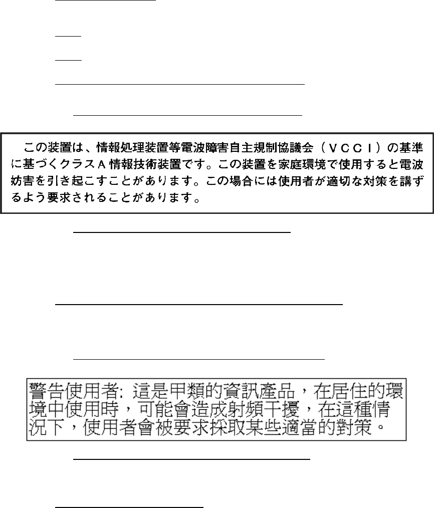
VCCI Compliance Statement (Japanese translation):
VCCI Compliance Statement (English translation): This is a Class A product based on
the Technical Requirement of the Voluntary Control Council for Interference (VCCI) by
information technology equipment. In a domestic environment, this product may
cause radio interference, in which case the user may be required to take corrective
action.
Taiwan: Bureau of Commodity Inspection and Quarantine (BCIQ) – This equipment com-
plies withBCIQ EMC Law—Taiwan: CNS13438.
The following warning label statement pertains to BSMI regulations in Taiwan, R.O.C.:
Taiwan Warning Label Statement (Taiwanese translation):
Taiwan Warning Label Statement (English translation): This is a Class A product. In a
domestic environment, this product may cause radio interference, in which case the
user may be required to take adequate measures.
CISPR 22 and EN55022 Warning – This is a Class A product. In a domestic environment
this product may cause radio interference in which case the user may be required to take
adequate measures.
96257 Sun Confidential: Internal Only xiv
Revision A
■Internal Code License Statement
NOTICE
INTERNAL CODE LICENSE
PLEASE READ THIS NOTICE CAREFULLY BEFORE INSTALLING AND OPERATING THIS EQUIPMENT. THIS NOTICE IS A LEGAL
AGREEMENT BETWEEN YOU (EITHER AN INDIVIDUAL OR ENTITY), THE END USER, AND SUN MICROSYSTEMS, INC. (‘SUN’),
THE MANUFACTURER OF THE EQUIPMENT. BY OPENING THE PACKAGE AND ACCEPTING AND USING ANY UNIT OF EQUIP-
MENT DESCRIBED IN THIS DOCUMENT, YOU AGREE TO BECOME BOUND BY THE TERMS OF THIS AGREEMENT. IF YOU
DO NOT AGREE WITH THE TERMS OF THIS AGREEMENT, DO NOT OPEN THE PACKAGE AND USE THE EQUIPMENT. IF YOU
DO NOT HAVE THE AUTHORITY TO BIND YOUR COMPANY, DO NOT OPEN THE PACKAGE AND USE THE EQUIPMENT. IF YOU
HAVE ANY QUESTIONS, CONTACT THE AUTHORIZED SUN DISTRIBUTOR OR RESELLER FROM WHOM YOU ACQUIRED THIS
EQUIPMENT. IF THE EQUIPMENT WAS OBTAINED BY YOU DIRECTLY FROM SUN, CONTACT YOUR SUN REPRESENTATIVE.
1.Definitions:
a. “Derivative works” are defined as works based upon one or more pre-
existing works, such as a translation or a musical arrangement, or any
other form in which a work may be recast, transformed, or adapted. A
work consisting of editorial revision, annotations, elaboration, or other
modifications which, as a whole, represent an original work of author-
ship, is a Derivative work.
b. “Internal Code” is Microcode that (i) is an integral part of Equipment, (ii)
is required by such Equipment to perform its data storage and retrieval
functions, and (iii) executes below the user interface of such Equip-
ment. Internal code does not include other Microcode or software, in-
cluding data files, which may reside or execute in or be used by or in
connection with such Equipment, including, without limitation, Mainte-
nance Code.
c. “Maintenance Code” is defined as Microcode and other software, in-
cluding data files, which may reside or execute in or be used by or in
connection with Equipment, and which detects, records, displays, and/
or analyzes malfunctions in the Equipment.
d. “Microcode” is defined as a set of instructions (software) that is either
imbedded into or is to be loaded into the Equipment and executes below
the external user interface of such Equipment. Microcode includes both
Internal Code and Maintenance Code, and may be in magnetic or other
storage media, integrated circuitry, or other media.
2. The Equipment you have acquired by purchase or lease is manufactured
by or for Sun and contains Microcode. By accepting and operating this
Equipment you acknowledge that Sun or its licensor(s) retain(s) owner-
ship of all Microcode, as well as all copies thereof, that may execute in or
be used in the operation of servicing of the Equipment and that such Mi-
crocode is copyrighted by Sun or its licensor(s).
3. Sun hereby grants you, the end user of the Equipment, a personal, non-
transferable (except as permitted in the transfer terms in paragraph 7 be-
low), nonexclusive license to use each copy of the Internal Code (or any
replacement provided by Sun or your authorized Sun distributor or re-
seller) which license authorizes you, the end user, to execute the Internal
Code solely to enable the specific unit of Equipment for which the copy of
Internal Code is provided to perform its data storage and retrieval func-
tions in accordance with Sun’s (or its licensor’s) official published speci-
fications.
4. Your license is limited to the use of the Internal Code as set forth in para-
graph 3 above. You may not use the Internal Code for any other purpose.
You may not, for example, do any of the following:
(a) access copy, display, print, adapt, alter, modify, patch, prepare Deriv-
ative works of, transfer, or distribute (electronically or otherwise) or
otherwise use the Internal Code;
(b) reverse assemble, decode, translate, decompile, or otherwise reverse
engineer the Internal Code (except as decompilation may be express-
ly permitted under applicable European law solely for the purpose of
gaining information that will allow interoperability when such informa-
tion is otherwise not readily available); or
(c) sublicense, assign, or lease the Internal Code or permit another per-
son to use such Internal Code, or any copy of it.
If you need a backup or archival copy of the Internal Code, Sun, or your
authorized Sun distributor or reseller, will make one available to you, it be-
ing acknowledged and agreed that you have no right to make such a copy.
5. Nothing in the license set forth in paragraph 3 above or in this entire No-
tice shall convey, in any manner, to you any license to or title to or other
right to use any Maintenance code, or any copy of such Maintenance
Code. Maintenance Code and Sun’s service tools and manuals may be
kept at your premises, or they may be supplied with a unit of Equipment
sent to you and/or included on the same media as Internal Code, but they
are to be used only by Sun’s customer service personnel or those of an
entity licensed by Sun, all rights in and to such Maintenance Code, ser-
vice tools and manuals being reserved by Sun or its licensors. You agree
that you shall not use or attempt to use the Maintenance Code or permit
any other third party to use and access such Maintenance Code.
6. You, the end user, agree to take all appropriate steps to ensure that all of
your obligations set forth in this Notice, particularly in paragraphs 4 and
5, are extended to any third party having access to the Equipment.
7. You may transfer possession of the Internal Code to another party only
with the transfer of the Equipment on which its use is authorized, and your
license to use the Internal Code is discontinued when you are no longer
an owner or a rightful possessor of the Equipment. You must give such
transferee all copies of the Internal Code for the transferred Equipment
that are in your possession, along with a copy of all provisions of this No-
tice. Any such transfer by you is automatically (without further action on
the part of either party) expressly subject to all the terms and conditions
of this Notice passing in full to the party to whom such Equipment is trans-
ferred, and such transferee accepts the provisions of this license by initial
use of the Internal Code. You cannot pass to the transferee of the Equip-
ment any greater rights than granted under this Notice, and shall hold Sun
harmless from any claim to the contrary by your transferee or its succes-
sors or assigns. In addition, the terms and conditions of this Notice apply
to any copies of Internal Code now in your possession or use or which you
hereafter acquire from either Sun or another party.
8. You acknowledge that copies of both Internal Code and Maintenance
Code may be installed on the Equipment before shipment or included with
the Equipment and other material shipped to you, all for the convenience
of Sun’s service personnel or service providers licensed by Sun, and that
during the warranty period, if any, associated with the Equipment, and
during periods in which the Equipment is covered under a maintenance
contract with Sun or service providers licensed by Sun, both Internal
Code and Maintenance Code may reside and be executed in or used in
connection with such Equipment, and you agree that no rights to Main-
tenance Code are conferred upon you by such facts. Sun or the licensed
service provider may keep Maintenance Code and service tools and
manuals on your premises but they are to be used only by Sun’s customer
service personnel or those of service providers licensed by Sun. You fur-
ther agree that upon (i) any termination of such warranty period or main-
tenance contract period; or (ii) transfer of possession of the Equipment to
another party, Sun and its authorized service providers shall have the
right with respect to the affected Equipment to remove all service tools
and manuals and to remove or disable all Maintenance Code and/or re-
place Microcode which includes both Internal Code and Maintenance
Code with Microcode that consists only of Internal Code.

xv Sun Confidential: Internal Only 96257
Revision A
Safety / Fiber Optic / ESD Precautions
The following precautions must be followed during all phases of equipment installation,
operation, and servicing. Equipment users are responsible for following warnings and
cautions, and for taking other appropriate steps to assure safe equipment operation. Sun
assumes no liability for failure to comply with these requirements.
■Safety Precautions
To prevent hazardous conditions and personal injury, follow these safety precautions:
Verify Proper Equipment Grounding
Ensure cabinet frames are properly connected to an electrical earth ground. AC power
supplies require a three-conductor power cable. Source power cables must be plugged in-
to approved three-contact electrical outlets. Power cable jacks and mating plugs must
meet electrical code requirements for the intended area of use and also comply with Inter-
national Electrotechnical Commission (IEC) safety standards.
Avoid Electric Shocks
Only qualified personnel may remove equipment covers for servicing. Before starting a
service procedure, remove conductive metal objects from your person including rings,
watches, necklaces, and badge chains. Use a conductive wrist strap and work mat
grounded to a jack or unpainted metal surface on a cabinet frame. Never touch exposed
connector pins or sockets, or leave ‘live’ cable ends exposed.
Use Only Approved Tools and Test Equipment
Use only approved tools and test equipment supplied in the standard CSE tool kit. Always
ground test equipment to a grounding jack on the cabinet frame. Repair or replace any
damaged tools or test equipment prior to use.
Be Aware of Your Operating Environment
Never operate electrical or electronic equipment in the presence of flammable gases or
fumes, as these can create an explosion hazard.
Never Service or Adjust Equipment Alone
Never service or adjustment equipment unless another person capable of rendering first
aid and resuscitation is present.
Do Not Substitute Parts or Modify Equipment
To assure equipment safety features are maintained, and to avoid introducing additional
hazards, never install substitute parts or modify Sun equipment without explicit permission
from Sun technical support personnel. Never remove, cut, or relocate raised-floor tiles
without first receiving customer permission.
Provide Adequate Equipment Clearances
Make sure there is sufficient clearance around equipment to facilitate airflow and heat dis-
sipation, and to maintain ambient system temperatures within recommended operating
ranges. Provide clearances that allow cabinet doors to open at least 90 degrees, and to
be easily removed for servicing equipment or in emergency situations.
96257 Sun Confidential: Internal Only xvi
Revision A
Strictly Comply With Caution and Warning Messages
To prevent injury and equipment damage, comply with all caution and warning messages
in this document. Also employ any and all other precautions which you deem necessary
for safe operation of equipment in your specific operating environment.
Carefully Follow Procedural Steps
Always complete procedural steps in listed order. Performing steps out of order can ex-
pose you to potentially hazardous or lethal conditions.
Protect Yourself From Moving Parts
Restrict loose clothing and long hair to avoid becoming entangled in moving parts such as
fans, impellers, and blowers.
Promptly Reinstall Covers and Doors
After completing service procedures, promptly reinstall cabinet covers, and close and lock
cabinet doors to maintain proper cabinet airflow, prevent overheating, and restrict accessi-
bility to energized FRUs.
Miscellaneous Safety Precautions
To prevent tipovers, never tilt a cabinet beyond a 15-degree angle (e.g., when ascending
or descending ramps). Use caution when working near open floor tiles. Use good house-
keeping practices to avoid fire hazards and to reduce the potential for mishaps.
■Electrostatic Discharge Precautions
Electrostatic discharge (ESD)-sensitive components must always be handled under pro-
tected conditions, and ESD-preventive equipment must be used when servicing equip-
ment. Employees who handles ESD-sensitive parts must be aware of the damage that
ESD can cause, and must take the following precautions to prevent it.
Use ESD-Preventive Equipment
Always use Field Service Grounding Kit P/N 4711 when installing or servicing Sun equip-
ment. Always use a conductive wrist strap and antistatic work mat, and ensure those are
grounded to a jack or unpainted metal on the cabinet frame when working.
Regularly Check and Clean ESD-Preventive Equipment
Regularly (at least monthly during frequent use) verify the resistance of wrist-strap
grounding cords to be between 0.8M ohm (Ω) and 1.2M ohm (Ω), and work mat cords to
be less than 1.2M ohm (Ω); replace damaged cords or any that do not meet these specifi-
cations. Regularly (at least monthly during frequent use) clean antistatic work mats; ACL
Conductive Cleaner is preferred for this purpose since it leaves no residue, but isopropyl
alcohol or a mild detergent and water solution can also be used.
Remove Conductive Personal Items
Before beginning service procedures inside a cabinet, remove all conductive metal ob-
jects from your person including rings, watches, necklaces, and badge chains.
Handle ESD-Sensitive Components Carefully
Keep circuit cards, ASICs, and other ESD-sensitive components away from ESD sources
and extraneous electrical currents. Keep parts in ESD-protective packaging until installa-
tion, and store removed ESD-sensitive parts in protective packaging.
xvii Sun Confidential: Internal Only 96257
Revision A
■Fiber Optic Component Handling Precautions
To prevent damage to optical fiber cables and connectors, and to mitigate inherent haz-
ards from laser-light emissions, always follow these general handling precautions:
Protect Your Eyes
Never aim the output of a laser, or of an optical fiber connected to a laser, directly into your
eyes. Do not examine an optical connector on any cable that is still attached to its data
transmission port, since laser light may be present in the cable. Before examining the end
of an optical fiber, verify that no laser-light signals are present. Always cap unused data
transmission ports on channel interface cards.
Handle Fiber Optic Components Gently
Handle fiber cables and connectors gently to prevent damage. Never grasp cables or con-
nectors with pliers or grippers, or attach pulling devices to them. Never bend fiber cables
(e.g., when routing along cable paths or guides) to a radius of <12 mm (<0.5 in.), and do
not coil cables to <96 mm (<3.74 in.) in diameter. Use strain-relief mechanisms to prevent
the weight of cables from damaging fibers. Protect cables from sharp edges or protru-
sions, heat sources, and other damaging conditions. Ensure that equipment openings and
floor cutouts have protective edging at cable contact points.
Prevent Contamination of Cable Ends
Avoid touching the core of optical cables, as this can contaminate fibers and prevent light
transmission. If a cable-end becomes contaminated, remove any loose debris using
canned air or by gently tapping the connector, then clean the cable-end with an approved
cleaning kit. Leave protective caps on cable-ends until cables are attached to a connector;
after disconnecting cables, always reinstall clean protective caps.

About This Guide
xviii Sun Confidential: Internal Only 96257
Revision A
About This Guide
■Product Overview
The Sun StorageTek Virtual Storage Manager® (VSM®) is a disk-based virtual tape sys-
tem that provides enterprise-class storage management capabilities for MVS-based sys-
tems. Its scalable design, which includes Virtual Tape Control System (VTCS) host soft-
ware and an intelligent Virtual Tape Storage Subsystem (VTSS) disk buffer, optimizes
streaming workloads and backup and recovery functions, reduces management over-
head, and maximizes tape capacity utilization to reduce data protection costs in a wide
range of storage environments.
■Intended Audience
This document is intended for use by Sun Microsystems personnel and other qualified ser-
vice providers (QSPs)1 involved with site planning, installation, configuration, testing, cer-
tification, servicing, and technical support of VSM5 system equipment.
Users of this document should have a working knowledge of the following concepts and
technologies: virtualization; Ethernet; FICON, fibre channel, and network topologies; tape
storage (tape drives and tape libraries); and disk storage.
■Providing Feedback About This Document
Your feedback helps ensure the accuracy and completeness of this document. Please di-
rect all comments regarding this publication to the Sun Learning Services e-mail feedback
system at slsfs@sun.com.
To assure proper handling of your correspondence, specify the publication name, part
number, edition number, and referenced page(s) in your e-mail. If you would like a person-
al response, you must also include your contact information. Submitted content becomes
the sole property of Sun.
■Optimizing Content For Electronic Viewing
If a digitized photograph, screen capture, line drawing, or other graphic has been reduced
to fit in this document, small text in the image may be unreadable when viewed in an Ado-
be Acrobat® PDF file at 100% or lower scaling on some electronic displays.
To correct this problem, use Acrobat Reader scaling tools to increase the image size until
affected text becomes legible. The amount of ‘upscaling’ required will depends on several
factors, including: the original point size of the text; the original dimensions and resolution
of the image; and how much the image was scaled down.
1. Third-party contractors certified and authorized by Sun to work with systems and equipment described in this guide.
96257 Sun Confidential: Internal Only xix
Revision A
■Alert Messages
Alert messages used within this document are presented as follows:
Note: A note provides emphasis or additional useful detail about a topic or proce-
dure, and can either precede or follow the information it references.
■Notational and Typographic Conventions
The following notational and typographic conventions are used throughout this document
to highlight special words, phrases, and actions.
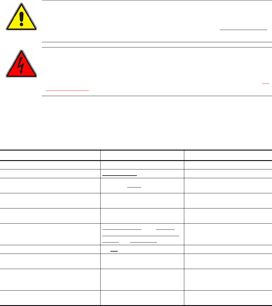
CAUTION !
A caution directs urgent attention to an action or condition which could dam-
age equipment or corrupt data or system software if the accompanying proce-
dure is not completed or is performed incorrectly. A caution always precedes
the information it references.
DANGER !!
A danger message directs urgent attention to an action or condition that has
potential to create a hazardous situation or to cause immediate, severe, and
possibly fatal injury or adverse long-term health effects if the accompanying
procedure is not completed or is performed incorrectly. A danger message al-
ways precedes the information it references.
Item Example(s) Description of Convention
Publications; course titles Installation and Service Guide Italic font
MS Windows or GUI screen titles Ethernet Setup screen Italic underlined font
Computer keyboard input keys Press the [Enter] key. Monospaced underlined font in
square brackets [ ]
User-keyed non-variable inputs; system-
generated outputs show systemstate Monospaced bold font
User-keyed variable inputs Name = <
system name
>Monospaced italic bold font in an-
gled brackets < >
E-mail and IP addresses; URLs; file and
folder names; active fields and icons in
GUI windows
glsfs@sun.com; click Submit;
www.support.storagetek.com;
cli.exe file; 129.80.64 subnet Monospaced underlined font
Emphasized text Do not touch exposed wiring... Underlined font
Physical VTSS labels for FRUs, LED indi-
cators, ports, or switches
POWER ON indicator; ETH0 port;
POWER ENABLE switch Bold caps font
Hypertext link (in PDF file) to a figure, ta-
ble, procedure step, or section heading
See Figure 2-1 on page 2-27; Re-
peat Step 3; See “Assigning Pass-
words” on page 4-11.
Blue font (prints black in black and
white photocopies)
Text references to numbered callouts in
accompanying artwork Pull the D-ring handle [3]. Bold font in bold square brackets [ ]

About This Guide
xx Sun Confidential: Internal Only 96257
Revision A
■Where to Find Additional Information
Additional information about the complete line of Sun StorageTek products and services is
provided through various media, as described below.
Reference Documents
The VSM5 Virtual Tape Storage Subsystem (VTSS) is one of several hardware and soft-
ware components that link together to create the VSM5 system. Besides this document, it
may be useful to consult some or all of the reference documents listed below to complete
planning, system assurance, installation, and service tasks for other VSM components de-
signed for a specific customer site.
Document Name and Part Number Availability
VSM Hardware
VTSS for VSM5 – Planning and System Assurance Guide, 96257 1
VTSS for VSM5 – Installation and Service Guide, 96254 1
T9x40 Tape Drive Planning and Migration Guide, MT6004 1
Nearline Physical Planning Guide, ML0041 1
Nearline Enterprise 9310/4410/9360 LSM System Assurance Guide, ML6500 1
TimberWolf 9740 Library Storage Module System Assurance Guide, MT5100 1
VSM Software
VTCS n.n * Quick Reference Guide 1, 2
VTCS n.n * Installation and Configuration Guide 1, 2
VTCS n.n * Administrator’s Guide 1, 2
VTCS n.n * Command and Utility Reference 1, 2
VTCS n.n * Messages and Codes 1, 2
VTCS n.n * XML Reference 1, 2
Remote Service and Support
Service Delivery Platform System Assurance Guide 1, 3
Service Delivery Platform Installation and Configuration Guide 1, 3
Notes:
1. Sun StorageTek Customer Resource Center (CRC) website: www.support.storagetek.com.
2. Sun StorageTek Software Manufacturing and Distribution – Web: www.support.storagetek.com, then under
CRC Tools click Software Manufacturing and Distribution; E-mail: LSVSMD-list@louisville.stortek.com; Phone:
U.S. (outside Colorado) and Canada 1.800.436.5554, International and within Colorado 1.303.673.8562.
3. Sun StorageTek Hardware Manual Scheduling – Phone: 1.303.673.6241.
• * Use documents labeled as version 6.0 or higher, which is the minimum host software level required for compatibil-
ity with VTSS back-end FICON channels.

96257 Sun Confidential: Internal Only xxi
Revision A
VSM Engineering Website
Extensive and detailed information about VSM, including engineering documents, Red-
books, White Papers, and standards, is available through the VSM Engineering website at
http://vsm.stortek.com. Website access is restricted to Sun employees.
Customer Resource Center
The Sun StorageTek Customer Resource Center (CRC) website at www.support
.storagetek.com provides resources including product documents, software keys, code
downloads, SE tools, and information on product education and training. Website access
is restricted to Sun employees, registered customers with a current warranty or mainte-
nance service agreement, and registered partners.
Product-Specific Documentation
The latest editions of documents for all Sun StorageTek products can be printed from PDF
files available on the CRC website; see ”Customer Resource Center” above for more in-
formation. VSM documents, including those for VTCS software and VTSS hardware, are
available through the path Current Products > Tape Products > Virtual Storage Manager
on the CRC website.
VTCS software documents, including a Quick Reference Guide, Installation and Configu-
ration Guide, Administrator’s Guide, Command and Utility Reference, Messages and
Codes, and XML Reference) also are provided on a CD-ROM that ships with each VSM
system. To order additional CDs, contact Sun StorageTek Software Manufacturing and
Distribution (SMD) at 800.436.5554, 303.673.8600, or www.support.storagetek.com, and
request the VTCS Information CD. To order individual software documents in bound-book
format, contact the SMD group.
Product Education and Training
The Sun StorageTek Learning Network website at http://learning.stortek.com provides
education and training courses for all Sun products, including the VTSS for VSM5. Web-
site access is restricted to Sun employees. Courses for the VSM5 system include:
• CRS100178 – VSM MVS System Administration for employees
• CRS100267 – VSM MVS System Administration for customers
• CRS-102711 – Detached Operator Panel (DOP) webinar
• CRS101nnn – VTSS for VSM5 Differences
• CRS100014 – SVA9500 and VSM Installation and Maintenance
• CRS101182 – FICON Native - T9X40 Tape Drive.

About This Guide
xxii Sun Confidential: Internal Only 96257
Revision A
SE Support Tools
SE tools, white papers, and other content for use with Sun StorageTek products, including
VSM5 system equipment, are available through the SE Support Tools website at
http://setools. Website access is restricted to Sun employees.
Global Services Field Support Tools
Resources to assist with sales and support of VSM5 system equipment and other Sun
StorageTek products and services are located on the Global Services Field Support Tools
website at http://sunsolve.central.sun .com/handbook_internal/FieldTools/. Website ac-
cess is restricted to Sun employees.
Storage Sales Community
Marketing collaterals and configuration documents for all Sun StorageTek products, in-
cluding VSM5 system equipment, are available on the Storage Sales Community website
at https://portal.storagetek.com/sales. Website access is restricted to Sun employees.
Partners
The Sun StorageTek Partners website at https://members.storagetek.com provides in-
formation about products, services, customer support, upcoming events, training pro-
grams, and sales tools to support Sun Partners. Website access is restricted to Sun em-
ployees and registered Sun partners.
‘Documents on CD’
Documents on CD is a set of CD-ROMs that contain documents for many Sun
StorageTek tape, disk, and storage networking products, and is shipped quarterly to field
offices. Contact your manager to obtain a current copy.
■Colophon
This document was created using Adobe FrameMaker 7.0 publishing software, and was
converted to a PDF (portable document format) file using Adobe Acrobat Writer 6.0 docu-
ment conversion software. Acrobat Reader software (Version 4.0 or higher)1 is required to
view PDF versions of this document.
1. This software can be downloaded free from www.adobe.com.
96257 Sun Confidential: Internal Only 1-23
Revision A
1
Planning and Implementation
Overview
This chapter provides an overview of key participants, timelines, and activities involved in
planning for and implementing a VSM5 system.
Successful implementation requires regular communication and coordination between
customer personnel and the Sun account team. This ongoing collaboration helps ensure
that all factors critical to the implementation are identified and addressed before equip-
ment is delivered to the site. The primary goals of the planning process are to:
• Ensure the VSM5 system is properly designed to meet the requirements of the custom-
er, and that it is ordered, delivered, installed, configured, tested, certified, and turned
over with a minumum of disruptions and problems
• Ensure the installation site infrastructure is equipped to handle the power, data-handling,
and environmental requirements of VSM5 system equipment, and that customer person-
nel are trained to assist with delivery, installation, configuration, testing, certification, and
operation of the VSM5 system equipment.
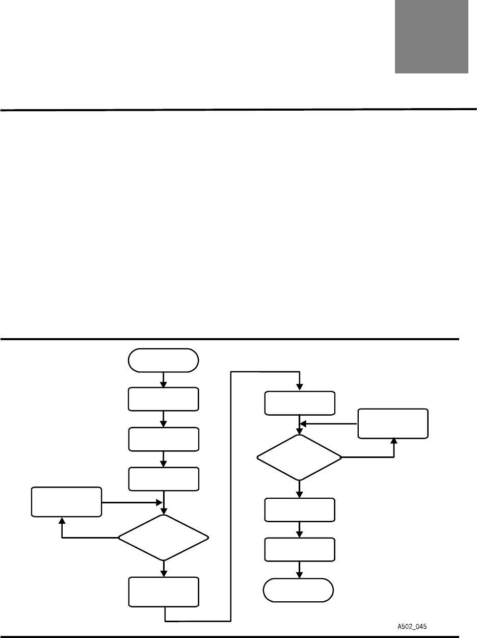
Figure 1-1. System Assurance Process Flow
START
END
Proposal Acceptance
System
Planning Meetings
Assurance
Installation
Ord Placementer
Post installation
Follow-up
SSC
SA Team for
More Information
or OM Contacts
SA Team Corrects
Pre-installation
Checklists
SSC
a Ship Date
or OM Approves
the Order and
Assigns
Are
Worksheets or Sales
Entry Forms Complete
and Correct
?
Order
Are the
Pre-Installation
Checklists Complete
and Correct
?
YES
YES
NO
NO
OM = Orders Management
SA = System Assurance
= Shared Ser Center
S
SC vices
System
Planning Meetings
Assurance

Planning and Implementation Overview
1-24 Sun Confidential: Internal Only 96257
Revision A
■Creating Planning Teams
Once a sales proposal has been accepted, the Sun customer service manager (CSM)
should confer with customer-site personnel including the network administrator, data cen-
ter manager, and facilities manager to identify which individuals who should be involved
with implementation planning, site readiness planning, and delivery and installation plan-
ning.
Customer and Sun personnel who participate in these planning teams jointly own and con-
trol the various processes, activities, and deliverables of those teams.
Once the team participants have been identified, one customer team member and one
Sun team member should be selected to act as coordinators for each team. Regular meet-
ings should be scheduled to:
• Define roles and responsibilities for all team members
• Define required implementation activities and task completion dates
• Identify and address issues that could impede delivery, installation, or implementation of
system equipment.
Forms and worksheets in Appendix D can be used by both customer and Sun planning
team members to record key system hardware and software information, identify planning
factors and considerations, and record completion dates for critical planning and imple-
mentation activities.
Customer membership for the various planning and implementation teams should consist
of:
• Persons who will determine the configuration and location of VSM5 system equipment,
including but not limited to: the data center manager; one or more network administra-
tors; the facilities manager; the site engineer, etc.
• Persons who will be directly involved with installation, testing, certification, and operation
of VSM5 system equipment, including but not limited to: facilities personnel; system op-
erators; network/IT personnel, etc.
• Persons who will be involved with delivery and dock-to-data center transit of VSM5 sys-
tem equipment, including but not limited to: the dock manager; dock personnel; facilities
personnel, etc.
Sun membership for the various teams may include some or all of the following: the sales
representative (SR); the local customer services manager (CSM); a systems engineers
(SE); a system support specialist (SSS); a technical support specialist (TSS); a profes-
sional services (PS) consultant; and a customer service engineer (CSE).

96257 Sun Confidential: Internal Only 1-25
Revision A
Planning / Readiness / Implementation Timelines
■Planning / Readiness / Implementation Timelines
The following activity guidelines allow sufficient time for planning, readiness, and imple-
mentation tasks to be completed prior to delivery of VSM5 system equipment to a custom-
er site.
1. Three months before the scheduled delivery date for the VSM5 system equipment:
• The network administrator, data center manager, and Sun account representative,
systems engineer (SE), and technical support specialist (TSS) define a system con-
figuration that best addresses customer requirements.
• The site engineer, facilities manager, and Sun Professional Services consultant re-
view site factors that present existing or potential safety and environmental hazards
which could negatively affect the operation of the VSM5 system. See “Site Evalua-
tion – External Considerations” and “Site Evaluation – Internal Considerations” on
page 4-46.
• The facilities manager and Sun Professional Services review equipment transfer re-
quirements and define a compliance plan as needed. See “Transfering Equipment
Point-to-Point” on page 4-47.
• The facilities manager and Sun Professional Services consultant review power sup-
ply and cabling requirements, and evaluate compliance to requirements. See “Site
Power Distribution Systems” on page 4-49.
• The site engineer, facilities manager, and structural engineer (if needed) review floor
construction and load ratings, and evaluate compliance. See “Floor Construction Re-
quirements” and “Floor Loading Requirements” on page 4-52.
• The network administrator, data center manager, and Sun technical support special-
ist review data cabling requirements for the VSM5 system configuration, and evalu-
ate compliance to requirements. See “Fibre Channel Cables — Available Lengths”
on page B-166.
• After completing reviews of power, environmental, flooring, and network connectivity
requirements, the site engineer and facilities manager schedule needed facilities up-
grades, targeting completion for not later than one week before delivery of system
equipment (two weeks is preferable).
2. Two months before the scheduled delivery date for the VSM5 system equipment:
• The site engineer and facilities manager create a floorplan/layout for all VSM5 sys-
tem equipment, and review it with the Sun Professional Services consultant. See
“Physical Space Requirements” on page 4-55.
Note: A copy of the final floorplan/layout should be given to the Sun sales represen-
tative to attach to the sales order.
• The facilities manager and Sun technical support specialist measure and record ca-
ble-layout distances between AC source power locations, host systems, network
servers, remote support devices, and VSM5 system hardware components.

Planning and Implementation Overview
1-26 Sun Confidential: Internal Only 96257
Revision A
• The dock manager and/or facilities manager and Sun customer service manager
identify any special shipping requirements, and notify the Sun manufacturing group
as needed.
• The Sun sales representative completes and submits the equipment sales order, in-
cluding all necessary cabling and spare parts.
• The network administrator and data center manager select appropriate personnel for
VSM5 system training, targeting completion for no later than one week before deliv-
ery of equipment.
3. One month before the scheduled delivery date for the VSM5 system equipment:
• The network administrator, data center manager, and Sun sales representative verify
that all required components in the specified configuration, and all cables of the re-
quired length, have been ordered.
• The Sun customer service manager reconfirms the scheduled system delivery date
with the Sun manufacturing facility.
• The facilities manager verifies compliance of input power systems and power cabling
in the data center. See “Site Power Distribution Systems” on page 4-49.
• The facilities manager verifies environmental compliance and HVAC systems readi-
ness in the delivery, staging, and installation areas.
• The site engineer and structural engineer verify floor loading compliance along the
delivery path and at the data center installation location. See “Floor Construction Re-
quirements” and “Floor Loading Requirements” on page 4-52.
• The Sun customer services manager identifies which Sun personnel will perform the
VSM5 system installation at the customer site.
4. Two weeks before the scheduled delivery date for the VSM5 system equipment:
• The Sun sales representative verifies that all parts and bills of material (BOM) have
been delivered to the site to allow hardware and software conversions and feature
changes in previously-installed equipment.
• The facilities manager and Sun customer service manager verify the delivery dock
and data center personnel, and Sun CSEs who will be available to accept delivery of
the system equipment, and assist in unpackaging, point-to-point transfer, and instal-
lation of system equipment.
• The facilities manager, data center manager, and Sun customer service manager
agree on firm dates and timeframes for delivery, installation, certification, and opera-
tional testing of system equipment.

96257 Sun Confidential: Internal Only 2-27
Revision A
2
Configuration Planning
This chapter provides an overview of configuration planning considerations and activities
that are used to design a VSM5 system tailored to customer requirements, and to ensure
proper implementation of the system.
Designing an optimized VSM5 system to meet specific customer requirements requires
close collaboration between Sun personnel (the account representative (AR), systems en-
gineers (SEs), and technical support specialists (TSSs)) and key customer decisionmak-
ers (network administrators, data center managers, etc.) who are involved with selecting
and implementing the system.
Planning for more complex system implementations may require consultation with the Sun
Global Professional Services group.
Table 2-1.Configuration Planning Overview
Key High-Level Activities Key Sub-Tasks Key Participants
• Define customer requirements.
• Assess budgetary constraints.
• Design an optimized VSM5 system
based on defined requirements
and constraints.
• Use sizing tools to estimate require-
ments and propose a VSM5 system
configuration
• Create high-level conceptual diagram
of proposed VSM5 system configura-
tion
• Create detailed engineering diagram of
proposed VSM5 system configuration
• Present VSM5 system physical and
functional configuration plans to key de-
cisionmakers
• Complete applicable Appendix D work-
sheets
•Customer
: network adminis-
trator; data center manager
•Sun
: account representative;
systems support specialist;
technical support specialist;
systems engineer
Configuration Planning
2-28 Sun Confidential: Internal Only 96257
Revision A
■Defining Customer Requirements
Customized tools are available to assist Sun personnel with estimating customer require-
ments and configuring a unique VSM5 system to meet those needs.
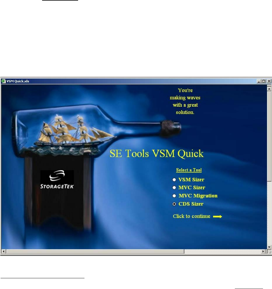
VSM Quick is a pre-sales tool package designed for use by SEs and ARs. It provides po-
tential customers with a quick estimate of the size and scope of a VSM5 system that is tai-
lored to their requirements.
VSM Quick and other VSM-related tools are available on the SE Tools website at
http://setools. Use of VSM Quick requires a Pentium system with a minimum of 128MB
RAM (256MB+ recommended), 8MB of free disk space, Windows 2000 or XP operating
system, and the MS Office Suite 2000 (or later).1
The VSM Quick tool package currently consists of four discrete tools: the VSM Sizer tool,
MVC Sizer tool, MVC Migration tool, and CDS Sizer tool, as described in the following
pages. Figure 2-1 shows the VSM Quick tool selection screen.
Detailed information on how to use each tool is available in the help file that accompanies
the download of the VSM Quick program.
Figure 2-1. VSM Quick Tool – Tool Selection Screen
1. Also, a CD-ROM with SE tools for many other StorageTek products is available on the SE tools website at http://setools, or
from the StorageTek Software Manufacturing and Distribution (SMD) group.
96257 Sun Confidential: Internal Only 2-29
Revision A
Defining Customer Requirements
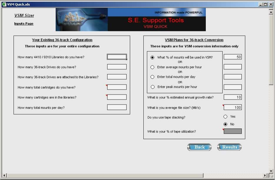
VSM Sizer Tool
As shown in Figure 2-2, the VSM Sizer tool requests inputs on mount activity, file size, the
estimated growth rate of data, and the current configuration of libraries, transports, and
cartridges to determine customer requirements for a VSM5 system.
Based on the results of its calculations, the tool identifies an optimum VSM5-VTSS config-
uration and minimum number of RTDs to meet the defined requirements. The tool also
suggests possible hardware reductions that could result from installing the proposed
VSM5 system.
Figure 2-2. VSM Sizer Tool
Configuration Planning
2-30 Sun Confidential: Internal Only 96257
Revision A
MVC Sizer Tool
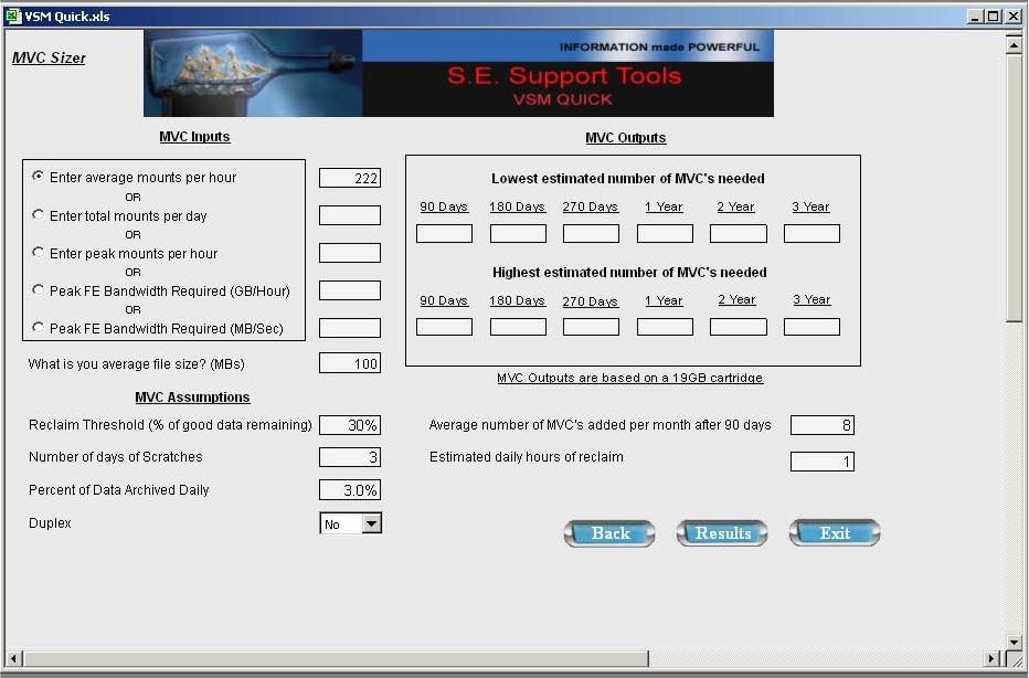
As shown in Figure 2-3, the MVC Sizer tool estimates the number of Multiple Volume Car-
tridges (MVCs) required for a VSM installation at intervals of 90 days, 180 days, 270 days,
one year, two years, and three years, based on mount activity and average file size.
The tool also reports estimated hours needed for daily reclaim activity, and the average
number of MVCs to be added on a monthly basis after the first 90 days.
Figure 2-3. MVC Sizer Tool
96257 Sun Confidential: Internal Only 2-31
Revision A
Defining Customer Requirements
MVC Migration Tool
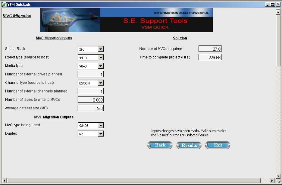
As shown in Figure 2-4, the MVC Migration tool evaluates existing tape systems, tape me-
dia, channels, and data set size to estimate the number of Multiple Volume Cartridges
(MVCs) required for a VSM installation at intervals of 90 days, 180 days, 270 days, one
year, two years, and 3 years, and the amount of time needed to migrate data from existing
manual or Nearline tape devices to the proposed VSM5 system.
Figure 2-4. MVC Migration Tool
Configuration Planning
2-32 Sun Confidential: Internal Only 96257
Revision A
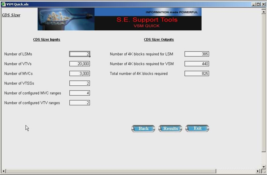
CDS Sizer Tool
As shown in Figure 2-5, the CDS Sizer is used to determine size requirements for the
HSC control data set (CDS) based on a specific VSM5 system configuration.
The tool requests detailed inputs about the VSM configuration (number of LSMs, VTVs,
MVCs, VTSSs, configured MVC ranges, and configured VTV ranges), then calculates the
number of 4K blocks needed in the HSC database to accommodate the LSM and VSM
configurations.
Figure 2-5. CDS Sizer Tool

96257 Sun Confidential: Internal Only 2-33
Revision A
VTSS Configuration Planning
■VTSS Configuration Planning
A VSM5 system consists of Virtual Tape Control System (VTCS) host software, Virtual
Tape Storage Subsystem (VTSS) disk hardware (tape buffers)1, real tape drives (RTDs)
which attach to an Automated Cartridge System (ACS), and automated cartridge systems
(ACSs), a.k.a. tape libraries.
A VSM5-VTSS connects to IBM S/390-equivalent data-streaming architectures and relat-
ed hardware2, and has front-end and back-end FICON connections. ESCON connections
are not available for VSM5-VTSS.
VSM5-VTSS Environmental Requirements
VSM5-VTSS Physical Characteristics
1. Both a primary VTSS and secondary VTSS can be used within a single system configuration.
2. Including, but not limited to: OS/390, z/OS, MVS, and VM host systems and FICON directors (switches) by Brocade, CNT, and
McData. Check with Sun product marketing for the latest certification and compatibility information for VSM systems.
Table 2-2. VSM5-VTSS Environmental Requirements
Environmental
Factor Shipping Environment
Limits*Storage Environment
Limits#Operating Environment
Limits
Temperature -40oC to +60oC
(-40o F to +140o F) 10oC to 40 C
(50o F to 104o F) 16oC to 32oC
(60o F to 90o F)
Thermal Change
(maximum rate/hr) 15 C
(27o F) 15oC
(27o F) 5oC
(9o F)
Humidity‡10% to 80% 10% to 80% 20% to 80%
Altitude 0m to 15,240m
(0 ft. to 50,000 ft.) 0m to 3050m
(0 ft. to 10,000 ft.) 0m to 2439m
(0 ft. to 8000 ft.)
Notes:
• Abbreviations key: C = Centigrade; F = Fahrenheit; ft. = foot / feet; m = meter(s)
• * The shipping environment must not exceed the storage environment limits longer than 10 days.
•# The storage environment must not exceed the operating environment limits longer than 60 days.
•‡ Humidity specifications exclude conditions that may cause condensation on disk drives.
Table 2-3. VSM5-VTSS Physical Characteristics
Physical Attribute Specification
Height 154.94cm (61.0 in.)
Width (with both side covers attached) 92.1cm (36.24 in.)
Depth (with front and rear doors attached) 77.1cm (30.34 in.)
Maximum Weight (with 64 array drives) 445kg (982 lbs.)
Footprint 7093.7cm2 (1099.5 in2)
Recommended Service Clearance, Front/Rear (door swing radius) 54.1cm (21.3 in.)
Recommended Left/Right Side Clearance (optional) 6.4cm (2.5 in.)

Configuration Planning
2-34 Sun Confidential: Internal Only 96257
Revision A
Model Numbers / Configurations / Capacities
Table 2-4. VSM5-VTSS Model Numbers / Configurations / Capacities
Base
Model
Number
Disk Arrays
Configuration Data Drives*
Total Capacity
Capacity
Feature
Code
PCap
Capacity#
Published
Effective 4:1
Capacity
Actual
Effective 4:1
Capacity‡
PCap
Utiliza-
tion#
VSMB-465 2 x 13 + 2 + 1
(32 drives*)
3737.6 GB
(1:1 uncompressed)
---------
14,950.4 GB
(4:1 compression)
Base model 330GB 1250GB 1320GB 8.8%
VC15 660GB 2500GB 2640GB 17.7%
VC16 1320GB 5000GB 5280GB 35.3%
VC21 1970GB 7500GB 7880GB 52.7%
VC18 2890GB 11,000GB 11,560GB 77.3%
VC19 3551GB 14,000GB 14,203GB 95.0%
VSMC-465 3 x 13 + 2 + 1
(48 drives*)
5606.4 GB
(1:1 uncompressed)
---------
22,425.5 GB
(4:1 compression)
Base model 4200GB 16,000GB 16,800GB 74.9%
VC22 4730GB 18,000GB 18,920GB 84.4%
VC23 5326GB 21,000GB 21,304GB 95.0%
VSMD-465 4 x 13 + 2 + 1
(64 drives*)
7475.2 GB
(1:1 uncompressed)
---------
29,900.7 GB
(4:1 compression)
Base model 6040GB 23,000GB 24,160GB 80.8%
VC24 6570GB 25,000GB 26,280GB 87.9%
VC25 7101GB 28,000GB 28,406GB 95.0%
Notes:
• Abbreviations key: GB = gigabyte(s) (109 bytes); PCap = Physical Capacity Control feature
•* 32-drive configuration = 26 data drives, 4 parity drives, 2 spare drives, 30 read actuators, and 13 write actuators;
48-drive configuration = 39 data drives, 6 parity drives, 3 spare drives, 45 read actuators, and 13 write actuators;
64-drive configuration = 52 data drives, 8 parity drives, 4 spare drives, 60 read actuators, and 13 write actuators.
•# PCAP utilization is the sum of PCap capacity divided by the uncompressed capacity of all data drives in a base
model. Example: Model VSMB-465 with capacity feature VC15 has a PCap capacity of 660GB and a data drive ca-
pacity of 3737.6GB (13 drives), or a 17.7% utilization rate. PCap utilization is capped to a maximum of 95% to en-
sure at least 5% of data drive space is available for free space collection.
•‡ Actual effective 4:1 capacity = PCap capacity with 4:1 compression, based on number of data drives per array
(13) x number of arrays (2, 3, or 4) x base capacity per drive (143.75GB).

96257 Sun Confidential: Internal Only 2-35
Revision A
VTSS Configuration Planning
Prerequisites for FICON Connectivity
Note: VTCS 5.1 code or later and VTSS code D01.01.00.17 or higher are required pre-
requisites for enabling front-end FICON connectivity between a VTSS and main-
frame (host) CPU or FICON director. VTCS 6.0 code or higher and VTSS code
D01.02.00.00 or higher are required prerequisites for enabling back-end FICON
connectivity between a VTSS and RTDs or cluster-links (Clinks).
In a VSM5-VTSS, front-end channel transfers are never synchronized with back-end array
transfers. As such, timing problems associated with channel extenders for traditional disk
storage systems do not apply to the VSM5-VTSS.
A VTSS must be ordered with minimum of 4 VCF3 cards for front-end FICON connections.
The field upgrade procedure is disruptive, i.e., the VTSS must be powered down and host
interfaces must be reconfigured after installing the VCF3 cards and 32-Port FICON option.
Whether FICON connectivity is provided through a factory-ordered unit or a field upgrade,
the 32-Port FICON option must be installed.
Prerequisites for front-end FICON connectivity to hosts and FICON directors are:
• Two VCF3 card pairs (four cards total)
• VTCS code level 5.1 or higher
• VTSS code level D01.01.00.17 or higher.
Prerequisites for back-end FICON connectivity to real tape drives (RTDs) and cluster-links
(Clinks) are:
• One or more VCF2 card pairs in place of a like number of ICE3 card pairs
• VTCS code level 6.0 or higher
• VTSS code level D01.02.00 or higher.
Additional Prerequisites for FICON RTDs
Additional prerequisites applicable only for back-end FICON connectivity to RTDs are:
• Minimum tape drive microcode levels
- 9840B tape drives = 1.35.304 or higher
- 9940B tape drives = 1.35.404 or higher
- 9940C tape drives = 1.35.504 or higher
- T10000 tape drives = 1.35.604 or higher
• 3490 Emulation Mode – All RTDs must use 3490 Emulation Mode, which is selected at
the T9X40 Emulation Mode submenu.
• Receive Buffer Frame Size – All RTDs must have their receive buffer frame size set to
2048 MB, which is selected at the T9X40 Port A/B Maximum Data Size submenu.
See Chapter 5 of the T9X40 Service Reference Manual, P/N 95740, for details on how to
verify code levels and set the parameters listed above.
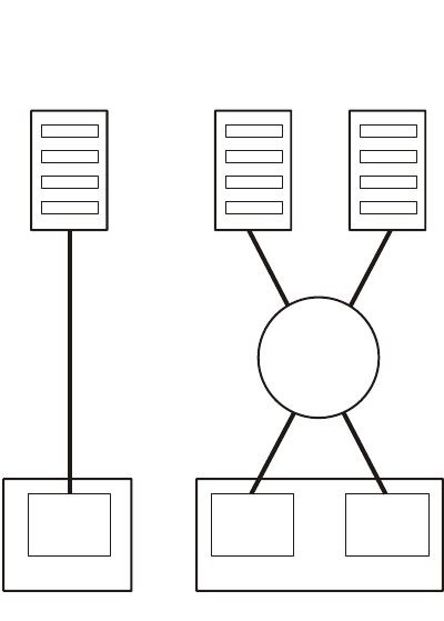
Configuration Planning
2-36 Sun Confidential: Internal Only 96257
Revision A
Native FICON Attachment
Native FICON attachment refers to a FICON CPU channel connected to a FICON control
unit interface, which may pass through a FICON director (switch). Since the connection is
all-FICON, all channels can provide the increased performance of FICON if the attached
devices are capable of FICON speeds.
Figure 2-6 illustrates the two attachment modes for native FICON: direct and switched. Di-
rect (point-to-point) attachment consists of a CPU FICON channel that connects directly to
a FICON control unit interface, without any intervening directors (switches).
Switched attachment is similar to direct attachment except that the FICON path passes
through a FICON switch, similar to an ESCON director. Adding a FICON director/switch
providee increased flexibility and connectivity similar to what ESCON directors provide,
but with the benefits and features of FICON.
Figure 2-6. Native FICON Attachment Options
Native FI
CO
N
C
hannel
(
F
C)
FICON Direct
Point-to-Point (FC) FICON Switched
Point-to-Point (FC)
FICON
Interface
VSM5 - VTSS
FICON
Interface
VSM5 - VTSS
FICON
Interface
FICON
Director
(Switch)
Host System Host System Host System
A504
_
020

96257 Sun Confidential: Internal Only 2-37
Revision A
VTSS Configuration Planning
FICON Data Transfer Rates
The fastest native FICON channels are rated at 200 MB/sec., but actually can achieve a
maximum data rate of only 170 MB/sec. under optimum conditions. In actual practice, FI-
CON typically operates at 40-60 MB/sec. using the 32 KB block size commonly found in
tape workloads.
VCF3 cards support 2 Gb link speeds; actual throughput speed is determined by many
factors including block size, microcode level, etc.
FICON Cabling — Short-Wave vs. Long-Wave Connections
Currently, FICON channels send data via fiber-optic cables only; copper-wire cables are
not supported. Fiber-optic data communiction cables are either single-mode or multi-
mode, as summarized in Table 2-5, and have these characteristics:
• Single-mode cables have a smaller core size than multi-mode, typically 8.5 or 9 microns,
and use long wavelengths to transmit data over greater distances (up to 10 km; 20 km
with an RPQ)1
• Multi-mode cables have a larger core size than single-mode cables, typically 50 or 62.5
microns, and use short wavelengths, which limits transmission range to distances less
than 500 m (1640 ft.). Multi-mode cables are more economical when long transmission
distances are not a requirement.
VCF2 (FICON) cards support both short- and long-wave connections through different
SFP connectors, which can be intermixed on individual cards. By default, VCF2 cards ship
with long-wave (LX) SFP connectors; an orderable option allows field upgrades to short-
wave (SX) connections.
LC Fibre connectors are used on both short- and long-wave SFPs, which requires use of
LC-LC or LC-SC cables for all VTSS-to-host connections.
Table 2-5. Single-Mode vs. Multi-Mode FICON Cabling
1. RPQ is not available with FICON channels rated at 200 MB/sec.
Mode Type Core Size Wavelength Color Max. Transmission Distance Relative Cost
Single-mode
(SM) 8.5 to 9
microns Long (LX) Yellow
• 10 km (6.2 mi.)
• 20 km (12.4 mi.) with RPQ
• 100 km (62 mi.) with repeaters
More
Multi-mode
(MM) 50 to 62.5
microns Short (SX) Orange •50 micron: ≤ 500 m (1640 ft.)
• 62.5 micron: ≤ 175 m (574 ft.)*Less
Note: * Requires mode-conditioner patch (MCP) cables, used in pairs. Data rates >100 MB/sec. are not supported
when MCP cables are used.
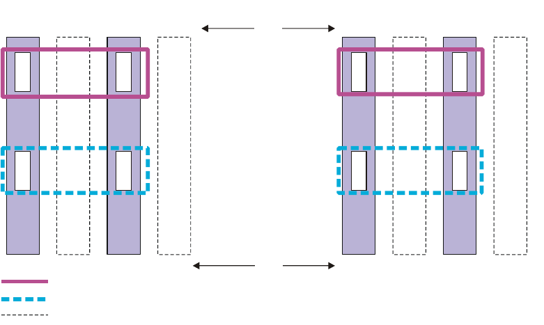
Configuration Planning
2-38 Sun Confidential: Internal Only 96257
Revision A
VCF3 (FICON) Card Configuration Examples
Note: VCF3 (FICON) cards must be installed and removed in pairs. A minimum VSM5-
VTSS configuration requires four VCF3 cards. Cards must be removed in the re-
verse order they were installed. Although there is no mechanism to restrict or sup-
port which slots VCF cards are placed in, configurations other than those shown in
Figure 2-7 through Figure 2-9 will not be supported.
As shown in Figure 2-7, the required minimum configuration of four VCF cards provides
eight physical FICON ports, and each port supports 64 host paths (512 paths total). The
first four VCF3 cards must be installed in slots VCF00, VCF02, VCF10, and VCF12.
Figure 2-7. FICON Channel Card Configuration – 4 VCF Cards
S
torage
C
luster 0
0A
0C
2
VCF00
3
VCF01
0I
0K
4
VCF02
5
VCF03
Channel-Link-Port 0
1A
1C
12
V
CF10
13
V
CF11
1I
1K
14
V
CF12
15
V
CF13
A504
_
07
0
Storage Cluster 1
Slot
Host Ports
RTD Ports
Card
Empty slot - no card installed
Channel-Link-Port 1
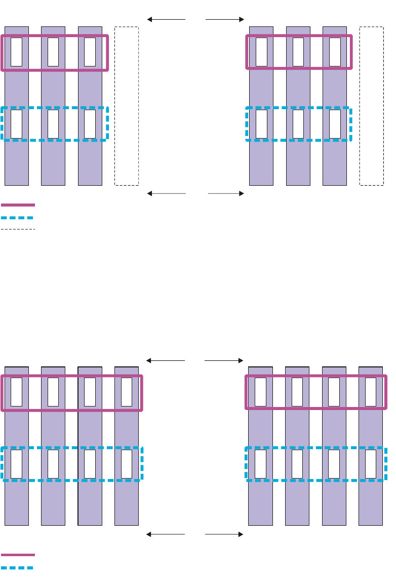
96257 Sun Confidential: Internal Only 2-39
Revision A
VTSS Configuration Planning
As shown in Figure 2-8, six VCF cards provide 12 physical FICON ports, and each port
supports 64 host paths (768 paths total). Cards must be installed in the slots shown (i.e.,
the third VCF3 card pair must be installed in slots VCF01 and VCF11).
Figure 2-8. FICON Channel Card Configuration – 6 VCF Cards
As shown in Figure 2-9, eight VCF cards provide 16 physical FICON ports, and each port
supports 64 host paths (1024 paths total). Cards must be installed in the slots shown (i.e.,
the third VCF3 card pair must be installed in slots VCF03 and VCF13).
Figure 2-9. FICON Channel Card Configuration – 8 VCF Cards
S
torage
C
luster 0
0A
0C
2
VCF00
0E
0G
3
VCF01
0I
0K
4
VCF02
5
VCF03
1A
1C
12
V
CF10
1E
1G
13
V
CF11
1I
1K
14
V
CF12
15
V
CF13
A504
_
069
Storage Cluster 1
Host Ports
RTD Ports
Empty slot - no card installed
Channel-Link-Port 0
Slot
Card
Channel-Link-Port 1
S
torage
C
luster 0
0A
0C
2
VCF00
0E
0G
3
VCF01
0I
0K
4
VCF02
0M
0O
5
VCF03
1A
1C
12
V
CF10
1E
1G
13
V
CF11
1I
1K
14
V
CF12
1M
1O
15
V
CF13
A504
_
06
4
Storage Cluster 1
Host Ports
RTD Ports
Channel-Link-Port 0
Slot
Card
Channel-Link-Port 1

Configuration Planning
2-40 Sun Confidential: Internal Only 96257
Revision A
■Fibre Channel Cables — Available Lengths
Table 2-6. Fibre Channel Cables – Available Lengths
Description / Length Part Number
LC-LC, 9/125, Duplex, Plenum, 10 meter (32.8 ft.), RoHS-5 10800330
LC-LC, 9/125, Duplex, Riser, 10 meter (32.8 ft.), RoHS-5 10800331
LC-LC, 9/125, Duplex, Plenum, 50 meter (164 ft.), RoHS-5 10800332
LC-LC, 9/125, Duplex, Riser, 50 meter (164 ft.), RoHS-5 10800333
LC-LC, 9/125, Duplex, Plenum, 100 meter (328 ft.), RoHS-5 10800305
LC-LC, 9/125, Duplex, Riser, 100 meter (328 ft.), RoHS-5 10800306
LC-SC, 9/125, Duplex, Plenum, 10 meter (32.8 ft.), RoHS-5 10800334
LC-SC, 9/125, Duplex, Riser, 10 meter (32.8 ft.), RoHS-5 10800335
LC-SC, 9/125, Duplex, Plenum, 50 meter (164 ft.), RoHS-5 10800336
LC-SC, 9/125, Duplex, Riser, 50 meter (164 ft.), RoHS-5 10800337
LC-SC, 9/125, Duplex, Plenum, 100 meter (328 ft.), RoHS-5 10800303
LC-SC, 9/125, Duplex, Riser, 100 meter (328 ft.), RoHS-5 10800304
SC-SC, 50/125, Duplex, Plenum, 10 meter (32.8 ft.), RoHS-5 10800294
SC-SC, 50/125, Duplex, Riser, 10 meter (32.8 ft.), RoHS-5 10800297
SC-SC, 50/125, Duplex, Plenum, 50 meter (164 ft.), RoHS-5 10800295
SC-SC, 50/125, Duplex, Riser, 50 meter (164 ft.), RoHS-5 10800298
SC-SC, 50/125, Duplex, Plenum, 100 meter (328 ft.), RoHS-5 10800296
SC-SC, 50/125, Duplex, Riser, 100 meter (328 ft.), RoHS-5 10800299
Notes:
• Order plenum-rated cables for sites where cables will be routed through HVAC ductwork. Plenum cables have fire-
retardant coating to prevent release of toxic gases and smoke in case of fire, so cost more than riser cables.
• Order riser cables for sites where cables will be installed in vertical riser shafts. Riser cables cannot be used in ple-
num areas unless specifically permitted by local codes. Riser cables provided by Sun are compliant with the stan-
dard flame spread test requirements outlined in UL specification 1666.
• When ordering cables, add a ‘service loop’ of at least 4.6 m (15 ft.) of extra cable at each end of the measured
VTSS-to-host length to allow the VTSS to be moved as needed for servicing, room reconfigurations, etc. Store ex-
tra cabling either on the floor beneath the VTSS or inside the VTSS, but not in an under-floor cable trough. If in
doubt as to where locate the loop, contact the data center manager or Sun Technical Support.

96257 Sun Confidential: Internal Only 2-41
Revision A
Fibre Channel Cables — Available Lengths
AC Source Power Specifications and Connectors
DC Power Supply Voltage Ripple Specifications
Table 2-7. VSM5-VTSS AC Source Power Specifications and Connectors
AC Source Power Requirement Power Specification
Power and Frequency Single-phase 170-240 VAC 30A @ 47-63 Hz
Heat Dissipation 4.77 minimum kBTU/hr — 7.64 maximum kBTU/hr
kVA 1.42 minimum kVA — 2.29 maximum kVA
Connector Type or Location Connector Specification
Sun-supplied VTSS power cables
(from VTSS power strips to AC source connector)
• RussellStoll RS3750DP* (North America only)
• No connector (all sites outside North America)
Customer-supplied wall receptacles or connector cables
(from AC source connector to VTSS power strips)
• RussellStoll RS 9R33u0W (rigid mount)
• RussellStoll RS 9C33U0 (flexible mount)
Notes:
• Abbreviations key: AC = alternating current; Hz = hertz; kVA = kilovolt-amperes; V = volt(s)
• * There is no equivalent Hubbell connector.
Table 2-8. VSM5-VTSS DC Power Supply Voltage Ripple
DC Power Supply Type Output Voltage Maximum Ripple (mV peak-to-peak)
Logic Power Supply 5.1 50
Array Power Supplies 5.1
12 (logic) 50
240

Configuration Planning
2-42 Sun Confidential: Internal Only 96257
Revision A
Power Requirements
Table 2-9. VSM5-VTSS Power Requirements — Single AC Source Power Cable Operation
Number of
16-Drive Arrays AC Source
Voltage In AC Source
Amps (Current) In kVA kW Power
Factor kBTUs
Per Hour
2
264V 10.1A 2.7 2.5 0.95 8.6
208V 12.4A 2.6 2.5 0.98 8.6
180V 16.2A 2.9 2.9 0.99 9.9
3
264V 13.0A 3.4 3.3 0.95 11.1
208V 16.0A 3.3 3.3 0.98 11.1
180V 18.3A 3.3 3.3 0.99 11.1
4
264V 14.5A 3.8 3.6 0.95 12.4
208V 17.8A 3.7 3.6 0.98 12.4
180V 20.3A 3.7 3.6 0.99 12.4
Notes:
• Abbreviations key: A = ampere(s); AC = alternating current; kBTUs = thousand British Thermal Units; kVA =
kilovolt-amperes; kW = kilowatts
Table 2-10. VSM5-VTSS Power Requirements — Dual AC Source Power Cable Operation
Number of
16-Drive Arrays AC Source
Voltage In AC Source
Amps (Current) In*kVA kW Power
Factor kBTUs
Per Hour
2
264V 5.6A 3.0 2.8 0.95 9.6
208V 6.9A 2.9 2.8 0.98 9.6
180V 7.9A 2.8 2.8 0.99 9.6
3
264V 6.3A 3.3 3.1 0.95 10.7
208V 7.7A 3.2 3.1 0.98 10.7
180V 8.8A 3.2 3.1 0.99 10.7
4
264V 6.9A 3.7 3.5 0.95 11.9
208V 8.5A 3.5 3.5 0.98 11.9
180V 9.8A 3.5 3.5 0.99 11.9
Notes:
•* Values are for each line cord; multiply this value by two to obtain the total current for both line cords.
• Abbreviations key: A = ampere(s); AC = alternating current; kBTUs = thousand British Thermal Units; kVA =
kilovolt-amperes; kW = kilowatts

96257 Sun Confidential: Internal Only 3-43
Revision A
3
Implementation Planning
This chapter provides an overview of implementation planning activities and tasks, which
are designed to ensure a VSM5 system is properly configured, tested, and certified ac-
cording to customer requirements.
Table 3-1 provides an overview of high-level activities, sub-tasks, and participants encom-
passed by the implementation planning process.
Table 3-1.Implementation Planning Overview
Key High-Level Activities Key Sub-Tasks Key Participants
• Select implementation planning team
members, and define roles and respon-
sibilities.
• Schedule and attend implementation
planning meetings.
• Determine task completion priorities
and scheduling.
• Define plan for integrating other devic-
es and systems with the VSM5 system
• Define plan for migrating data from oth-
er devices and systems to the VSM5
• Determine default settings for the
VSM5 system
• Define plan for configuring and manag-
ing system hardware (channel resourc-
es, physical disk, RTDs, etc.)
• Define plan for configuring and manag-
ing VSM5 system software (ExPR, Ex-
LM, HSC, MVS, NCS, VTCS, etc.)
• Define policies for configuring and
managing VSM5 system virtual enti-
ties (CLINKs, Nearlinks, VACSs, VTDs,
VTVs, etc.)
• Define plan for performance tuning,
testing, and certification of the VSM5
system
• Assess personnel requirements for
knowledge-transfer and hands-on
training; facilitate scheduling and com-
pletion of training activities.
• Complete applicable Appendix D work-
sheets
•Customer
: network adminis-
trator; system administrator;
data center manager; system
operator
•Sun
: professional services
personnel (delivery consult-
ant; systems support special-
ist; technical support special-
ist; systems engineer)
Implementation Planning
3-44 Sun Confidential: Internal Only 96257
Revision A
The implementation planning process is designed to identify and schedule completion of
configuration, performance tuning, and performance testing activities for a VSM5-VTSS
after it has been physically installed at a site.
A team comprised of key customer personnel (systems administrator; network administra-
tor; data center manager, system operator, etc.) and Sun Professional Services personnel
(technical support specialist; systems engineer; customer service manager, etc.) works to
complete these primary tasks:
• Defining a plan for integrating existing devices and systems with the VSM5 system
• Defining a plan to migrate data from other devices and systems to the VSM5 system
• Defining a plan to accomodate the physical layout and floor space requirements of the
VSM5-VTSS and other system devices
• Defining a plan for configuring the VSM5 system hardware (channel resources, physical
disk, RTDs, etc.), software (ExPR, ExLM, HSC, MVS, NCS, VTCS, etc.), and virtual enti-
ties (CLINKs, Nearlinks, VACSs, VTDs, VTVs, etc.)
• Defining a plan for completing performance tuning, performance testing, and certification
of VSM5 system hardware and software in the data center environment
• Identifying personnel training needs and scheduling appropriate knowledge-transfer
training sessions.
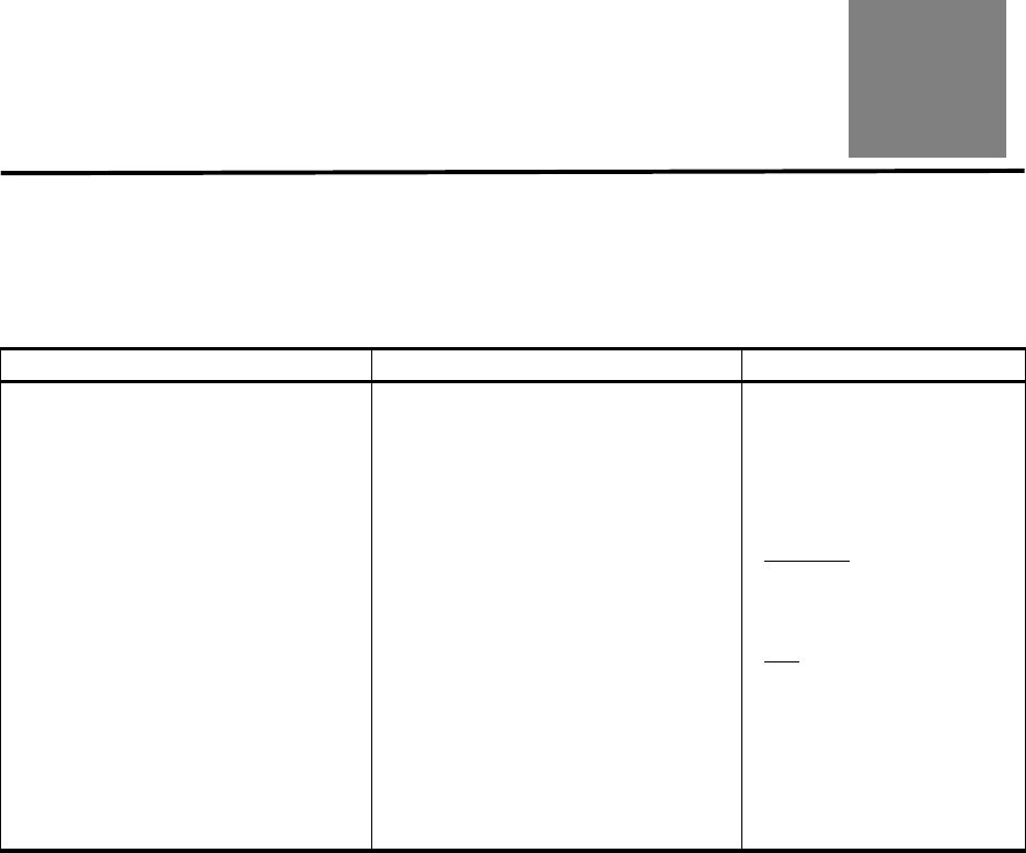
96257 Sun Confidential: Internal Only 4-45
Revision A
4
Site Readiness Planning
This chapter provides information about activities designed to ensure the site is equipped
to accommodate the power, safety, environmental, HVAC, and data handling requirements
of VSM5 system equipment.
Key site readiness planning considerations include, but are not limited to:
• Site surveys to evaluate and eliminate or mitigate factors which could negatively affect
delivery, installation, and operation of VSM5 system equipment.
• A plan for the layout and location of VSM5 system equipment and cabling that allows for
efficient use and easy maintenance, plus adequate space and facilities for Sun support
personnel and their equipment.
• Facilities construction that provides an optimum operating environment for VSM5 sys-
tem equipment and personnel, as well as safe flooring and protection from fire, flooding,
contamination, and other potential hazards.
• Scheduling of key events and task completion dates for facilities upgrades, personnel
training, and delivery, implementation, installation, testing, and certification activities.
Customers ultimately are responsible for ensuring that their site is physically prepared to
receive and operate VSM5 system equipment, and that the site meets the minimum spec-
ifications for equipment operation as detailed in this guide.
Table 4-1.Site Readiness Planning Overview
Key High-Level Activities Key Sub-Tasks Key Participants
• Select site readiness team members,
and define roles and responsibilities.
• Complete site surveys to:
- Document existing or potential exter-
nal and internal environmental haz-
ards
- Assess site power, safety, environ-
mental, HVAC, and data handling ca-
pabilities versus VSM5 system re-
quirements
- Confirm floor load ratings along the
transit path and at the installation lo-
cation for VSM5-VTSS cabinets
- Assess ceiling, hallway, and door
clearances, elevator capacities, and
ramp angles versus VSM5-VTSS
cabinet requirements.
• Attend planning meetings.
• Verify site power, safety, environmen-
tal, HVAC, and data handling capabili-
ties match VSM5-VTSS requirements.
• Define plan to eliminate/mitigate envi-
ronmental hazards.
• Evaluate floor load ratings along transit
path and at the VSM5-VTSS installa-
tion location.
• Verify site door, hall and ceiling clear-
ances, elevator capacity, ramp angles,
etc. match VSM5-VTSS requirements.
• Identify required infrastructure modifi-
cations/upgrades; set work completion
schedule.
• Evaluate readiness progress, and certi-
fy site readiness.
• Complete applicable Appendix D work-
sheets.
•Customer
: site engineer; fa-
cilities manager; data center
manager; network adminis-
trator
•Sun
: technical support spe-
cialist; systems engineer

Site Readiness Planning
4-46 Sun Confidential: Internal Only 96257
Revision A
■Site Evaluation – External Considerations
Several months before delivery of VSM5 system equipment, a readiness planning team
should identify and evaluate all external site factors that present existing or potential haz-
ards, or which could adversely affect delivery, installation, or operation of the system. Ex-
ternal factors that should be evaluated include:
• Reliability and quality of electrical power provided by the local utility, backup power gen-
erators, and uninterruptible power supplies (UPSs), etc.
• Proximity of high-frequency electromagnetic radiation sources (e.g., high-voltage power
lines; television, radio, and radar transmitters)
• Proximity of natural or man-made floodplains and the resultant potential for flooding in
the data center
• Potential effects of pollutants from nearby sources (e.g., industrial plants).
If any existing or potential negative factors are discovered, the site readiness planning
team should take appropriate steps to eliminate or mitigate those factors before VSM5
system equipment is delivered. Sun Global Services offers consultation services and other
assistance to identify and resolve such issues. Contact your Sun account representative
for more information.
■Site Evaluation – Internal Considerations
Several months before delivery of VSM5 system equipment, a readiness planning team
should identify and evaluate all internal site factors that present existing or potential haz-
ards, or which could adversely affect delivery, installation, or operation of the system. In-
ternal factors that should be evaluated include:
• Structural dimensions, elevator capacities, floor-load ratings, ramp inclines, and other
considerations when transfering equipment point-to-point between the delivery dock,
staging area, and data center installation site
• Site power system(s) design and capacity
• VSM5 system equipment power system design and capacity
• Data center safety system design features and capabilities
• Data center environmental (HVAC) design features and capabilities
• Potential effects of corrosive materials, electrical interference, or excessive vibration
from sources in close proximity to system equipment.
If any existing or potential negative factors are discovered, the site readiness planning
team should take appropriate steps to eliminate or mitigate those factors before VSM5
system equipment is delivered. Sun Global Services offers consultation services and other
assistance to identify and resolve such issues. Contact your Sun account representative
for more information.

96257 Sun Confidential: Internal Only 4-47
Revision A
Site Evaluation – Internal Considerations
Transfering Equipment Point-to-Point
Site conditions must be verified to ensure all VSM5 system equipment can be safely trans-
ported between the delivery dock, staging area, and data center without encountering di-
mensional restrictions, obstructions, or safety hazards, or exceeding rated capacities of
lifting and loading equipment, flooring, or other infrastructure. Conditions that must to be
verified are described below.
Structural Dimensions and Obstructions
Dimensions of elevators, doors, hallways, etc. must be sufficient to allow unimpeded tran-
sit of VSM5-VTSS cabinets (in shipping containers, where appropriate) from the delivery
dock to the data center installation location. See “VSM5-VTSS Physical Characteristics”
on page 2-33 for VTSS cabinet-dimension details.
Elevator Lifting Capacities
Any elevators that will be used to transfer VSM5-VTSS cabinets must have a certified load
rating of at least 1000 kg (2200 lbs.). This provides adequate capacity to lift the heaviest
packaged, fully-popuated VTSS cabinet (roughly 480 kg/1056 lbs. with 64 array drives), a
pallet jack (allow 100 kg/220 lbs.), and two persons (allow 200 kg/440 lbs.). See “VSM5-
VTSS Physical Characteristics” on page 2-33 for additional cabinet-weight details.
Floor-Load Ratings
Solid floors, raised floors, and ramps located along the transfer path for VSM5-VTSS cab-
inets must be able to withstand concentrated and rolling loads generated by the weight of
a populated cabinet, equipment used to lift a cabinet (e.g., a pallet jack), and personnel
who are moving the cabinet from point to point.
Raised floor panels located along a transfer path must be able to resist a concentrated
load of 454 kg (1000 lbs.) and a rolling load of 181 kg (400 lbs.) anywhere on the panel,
with a maximum deflection of 2 mm (0.08 in.). Raised floor pedestals must be able to re-
sist an axial load of 2268 kg (5000 lbs.). See “Floor Loading Requirements” on page 4-52
for additional floor-loading details.
When being moved from one location to another, a VSM5-VTSS cabinet generates rough-
ly twice the floor load as in a static state. Using 19 mm (0.75 in.) plywood along a transfer
path reduces the rolling load produced by a cabinet.
Ramp Inclines
To prevent VSM5-VTSS cabinets from tipping on ramps while being moved from point to
point, the site engineer or facilities manager must verify the incline angle of all ramps in
the transfer path. Inclines cannot exceed 10 degrees (176 mm/m; 2.12 in./ft.).
Site Readiness Planning
4-48 Sun Confidential: Internal Only 96257
Revision A
Data Center Safety
Safety must be a primary consideration in planning installation of VSM5 system equip-
ment, and is reflected in such choices as where equipment will be located, the rating and
capability of electrical, HVAC, and fire-prevention systems that support the operating envi-
ronment, and the level of personnel training. Requirements of local authorities and insur-
ance carriers will drive decisions as to what constitutes appropriate safety levels in a given
environment.
Occupancy levels, property values, business interruption potential, and fire-protection sys-
tem operating and maintenance costs should also be evaluated. The Standard for the
Protection of Electronic Computer / Data Processing Equipment (NFPA 75), the Na-
tional Electrical Code (NFPA 70), and local and national codes and regulations can be
referenced to address these issues.
Emergency Power Control
The data center should be equipped with readily-accessible emergency power- off switch-
es to allow immediate disconnection of electrical power from VSM5 system equipment.
One switch should be installed near each principal exit door so the power-off system can
be quickly activated in an emergency. Consult local and national codes to determine re-
quirements for power disconnection systems.
Fire Prevention
The following fire-prevention guidelines should be considered in the construction, mainte-
nance, and use of a data center:
• Store gases and other explosives away from the data center environment.
• Ensure data center walls, floors, and ceilings are fireproof and waterproof.
• Install smoke alarms and fire suppression systems as required by local or national
codes, and perform all scheduled maintenance on the systems.
Note: Halon 1301 is the extinguishing agent most commonly used for data center fire
suppression systems. The agent is stored as a liquid and is discharged as a
colorless, odorless, electrically nonconductive vapor. It can be safely dis-
charged in occupied areas without harm to personnel. Additionally, it leaves no
residue, and has not been found to cause damage to computer storage media.
• Install only shatterproof windows, in code-compliant walls and doors.
• Install carbon dioxide fire extinguishers for electrical fires and pressurized water extin-
guishers for ordinary combustible materials.
• Provide flame-suppressant trash containers, and train personnel to discard combustible
waste only into approved containers.
• Observe good housekeeping practices to prevent potential fire hazards.
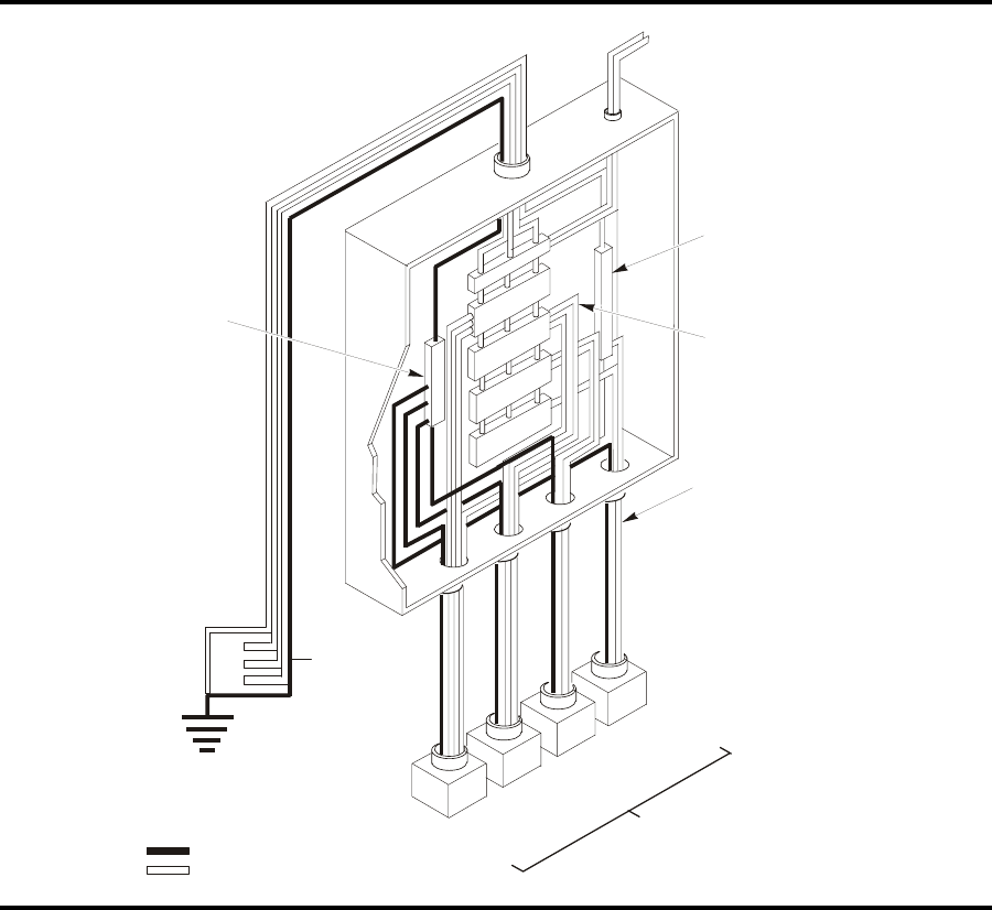
96257 Sun Confidential: Internal Only 4-49
Revision A
Site Evaluation – Internal Considerations
Site Power Distribution Systems
The following elements of the site power distribution system should be evaluated when
planning an installation of VSM5 system equipment.
System Design
A properly installed power distribution system is required to ensure safe operation of
VSM5 system equipment. Power should be supplied from a feeder separate from one
used for lighting, air conditioning, and other electrical systems.
A typical input power configuration, shown in Figure 4-1, is either a five-wire high-voltage
or a four-wire low-voltage type, with three-phase service coming from a service entrance
or separately derived source, and with overcurrent protection and suitable grounding. A
three-phase, five-wire distribution system provides the greatest configuration flexibility,
since it allows power to be provided to both three-phase and single-phase equipment.
Figure 4-1. Site Electrical Power Distribution System
Circuit Breakers of
Appropriate Size
Neutral Bus
Remotely Operated
Power Service Disconnect
Computer Room
Power Panel
G
round Terminal Bar
be
S
ame size as neutral
(
onded to nclosure)
Neutral
Ground Service Entrance
Ground or Suitable
Building Ground
Note:
Bounding of neutral and ground at other
points is Illegal.
Only valid at
service entrance
or separately
derived system
(transformer)
Insulated Green Wire Ground
Phase Wires and Neutral
Ledgend: Customer Supplied
Receptacles/Connectors-
in Accordance with
Local Codes
208/240V
3-Phase
(5-wire)
208/240V
3-Phase
(4-wire)
208/240V
Single
Phase
120V
Single
Phase
Branch Circuits
For loads requiring a
neutral attach computer/da
ta
processing equipment only
A502_046
*
*
I
ncoming Three-phase Power
f
rom service entrance or
s
eparately derived system
w
ith appropriate over-current
p
rotection and suitable ground

Site Readiness Planning
4-50 Sun Confidential: Internal Only 96257
Revision A
Equipment Grounding
For safety and ESD protection, VSM5 system equipment must be properly grounded.
VTSS cabinet power cables contain an insulated green/yellow grounding wire that con-
nects the frame to the ground terminal at the AC source power outlet. A similar insulated
green or green/yellow wire ground, of at least the same diameter as the phase wire, is re-
quired between the branch circuit panel and the power receptacle that attaches to each
cabinet.
Source Power Input
Voltage and frequency ranges at the AC source power receptacle(s) that will supply power
to VSM5 system equipment must be measured and verified to meet the specifications
shown in Table 4-2.
Table 4-2. Source Power Requirements for VSM5 Equipment
Dual Independent Source Power Supplies
VSM5-VTSS cabinets have a redundant power distribution architecture designed to pre-
vent disruption of system operations from single-source power failures.
To enable this capability, the two VTSS cabinet power-strip cables must be connected to
separate, independent power sources that are unlikely to fail simultaneously (e.g., one to
local utility power, the other to an uninterruptible power supply (UPS) system). Connecting
both cabinet power-strip cables to the same power source will not enable this redundant
power capability.
Transient Electrical Noise and Power Line Disturbances
Reliable AC source power free from interference or disturbance is required for optimum
performance of VSM5 system equipment. Most utility companies provide power that can
properly operate system equipment. However, equipment errors or failures can be caused
when outside (radiated or conducted) transient electrical noise signals are superimposed
on power provided to equipment.
Additionally, while VSM5 system equipment is designed to withstand most common types
of power line disturbances with little or no effect on operations, extreme power disturbanc-
es such as lightning strikes can cause equipment power failures or errors if steps are not
taken to mitigate such disturbances.
To mitigate the effects of outside electrical noise signals and power disturbances, data
center source power panels should be equipped with a transient grounding plate similar to
that shown in Figure 4-2 on page 4-51.
Source Power Voltage Range Frequency Range (Hz)
AC, single-phase, 3-wire 170-240 47-63
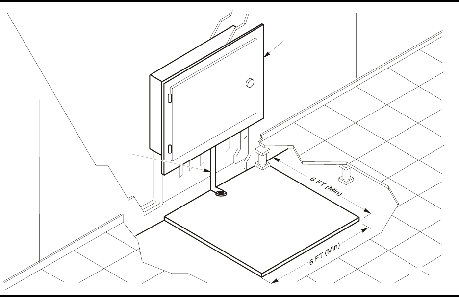
96257 Sun Confidential: Internal Only 4-51
Revision A
Site Evaluation – Internal Considerations
Electrostatic Discharge
Electrostatic discharge (ESD; static electricity) is caused by movement of people, furni-
ture, and equipment. ESD can damage circuit card components, alter information on mag-
netic media, and cause other equipment problems. The following steps are recommended
to minimize ESD potential in the data center:
• Provide a conductive path from raised floors to ground.
• Use floor panels with nonconducting cores.
• Maintain humidity levels within recommended control parameters.
• Use grounded anti-static work mats and wrist straps to work on equipment.
HVAC Requirements
Cooling and air-handling systems must have sufficient capacity to remove heat generated
by equipment and data center personnel. Raised-floor areas should have positive under-
floor air pressure to facilitate airflow. If conditions change within a data center (e.g., when
new equipment is added or existing equipment is rearranged), airflow checks should be
done to verify sufficient airflow.
Figure 4-2. Transient Electrical Grounding Plate
A502_047
Concrete Floor
Plate
Power
Panel
Flat
Braded/
Straned
Wire

Site Readiness Planning
4-52 Sun Confidential: Internal Only 96257
Revision A
Environmental Requirements and Hazards
VSM5 system components are sensitive to corrosion, vibration, and electrical interference
in enclosed environments such as data centers. Because of this sensitivity, equipment
should not be located near areas where hazardous and/or corrosive materials are manu-
factured, used, or stored, or in areas with above-average electrical interference or vibra-
tion levels.
For best performance, equipment should be operated at nominal environmental condi-
tions.If VSM5 system equipment must be located in or near adverse environments, addi-
tional environmental controls should be considered (and implemented where practicable)
to mitigate those factors prior to installation of the equipment.
Floor Construction Requirements
VSM5 system equipment is designed for use on either raised or solid floors. Carpeted sur-
faces are not recommended since these retain dust and contribute to the buildup of poten-
tially damaging electrostatic charges. A raised floor is preferable to a solid floor since it
permits power and data cables to be located safely away from floor traffic and other poten-
tial floor-level hazards.
Floor Loading Requirements
Flooring with an overall (superimposed) load rating of 490 kg/m2 (100 lbs./ft2) is recom-
mended. If floors do not meet this rating, a site engineer or facilities manager must consult
the floor manufacturer or a structural engineer to calculate actual loads and determine if
the weight of a particluar VSM5 system configuration can be safely supported.
When being moved from one location to another, a VSM5-VTSS system cabinet gener-
ates roughly twice the floor load as in a static state. Using 19 mm (0.75 in.) plywood along
a transfer path reduces the rolling load produced by a cabinet.
DANGER !!
Exceeding recommended raised-floor loads can cause a floor collapse, which
could result in severe injury or death, equipment damage, and infrastructure
damage. It is advisable to have a structural engineer perform a floor-load anal-
ysis before beginning installation of VSM5 system equipment.
CAUTION !
When being moved, a VTSS cabinet creates almost twice the floor load as
when static. To reduce floor load and stress, and the potential for damage or
injury when moving a VTSS (e.g., during installation), consider using 19 mm/
0.75 in. plywood on the floor along the path where the cabinet will be moved.

96257 Sun Confidential: Internal Only 4-53
Revision A
Site Evaluation – Internal Considerations
Floor Loading Specifications and References
Table 4-3. VSM5-VTSS Floor Loading Specifications
Basic Floor Load*Maximum Superimposed Floor Load #
730 kg/m2 (149 lbs./ft2)485 kg/m2 (99 lbs./ft2)
Notes:
•* Load over footprint surface area (7093.7 cm2/1099.5 in2) of an unpackaged VSM5-VTSS cabinet, with a maxi-
mum weight of 445 kg/982 lbs., i.e., a VTSS with 64 array disk drives.
•# Assumes minimum Z+Z axis dimension of 185.3 cm/73.0 in. (i.e., cabinet depth 77.1 cm/30.4 in. + front service
clearance of 54.1 cm/21.3 in. + rear service clearance of 54.1 cm/21.3 in.), minimum X+X axis dimension of 104.9
cm/41.2 in. (i.e., cabinet width 92.1 cm/36.3 in. + left clearance of 6.4 cm/2.5 in. + right clearance of 6.4 cm/2.5 in.).
Table 4-4. VSM5-VTSS Cabinet Superimposed Floor Loading Example
Total Front + Rear Service Clearance (Z+Z) / 2
Total Left + Right Side Clearance (X+X) / 2
7.6 cm
(3.0 in.) 61.0 cm
(24.0 in.) 91.4 cm
(36.0 in.) 121.9 cm
(48.0 in.) 152.4 cm
(60.0 in.)
55.9 cm
(22.0 in) 443 kg/m2
(91 lb./ft2)340 k.g/m2
(70 lb/ft2)308 kg/m2
(63 lb./ft2)285 kg/m2
(58 lb./ft2)268 kg/m2
(55 lb./ft2)
96.5 cm
(38.0 in) 374 kg/m2
(77 lb./ft2)295 k.g/m2
(60 lb/ft2)270 kg/m2
(55 lb./ft2)252 kg/m2
(52 lb./ft2)239 kg/m2
(49 lb./ft2)
116.8 cm
(46.0 in) 350 kg/m2
(72 lb./ft2)279 kg/m2
(57 lb./ft2)257 kg/m2
(53 lb./ft2)241 kg/m2
(49 lb./ft2)229 kg/m2
(47 lb./ft2)
137.2 cm
(54.0 in) 331 kg/m2
(68 lb./ft2)267 kg/m2
(55 lb./ft2)247 kg/m2
(51 lb./ft2)232 kg/m2
(48 lb./ft2)222 kg/m2
(45 lb./ft2)
157.5 cm
(62.0 in) 315 kg/m2
(64 lb./ft2)256 kg/m2
(52 lb./ft2)238 kg/m2
(49 lb./ft2)225 kg/m2
(46 lb./ft2)215 kg/m2
(44 lb./ft2)
Notes:
• See Figure 4-3 on page 4-53 for the location and load of each VTSS cabinet support point.
• Values assume 15 lb./ft2 (73 kg/m2) superimposed dead load over entire area for raised floor, cables, etc., and
15 lb./ft2 (73 kg/m2) live load for personnel and equipment in clearance areas between units.
• Loading of adjacent floor areas must be considered when evaluating overall floor capacity.
• To evaluate floor loading for other possible configurations, consult a structural engineer.
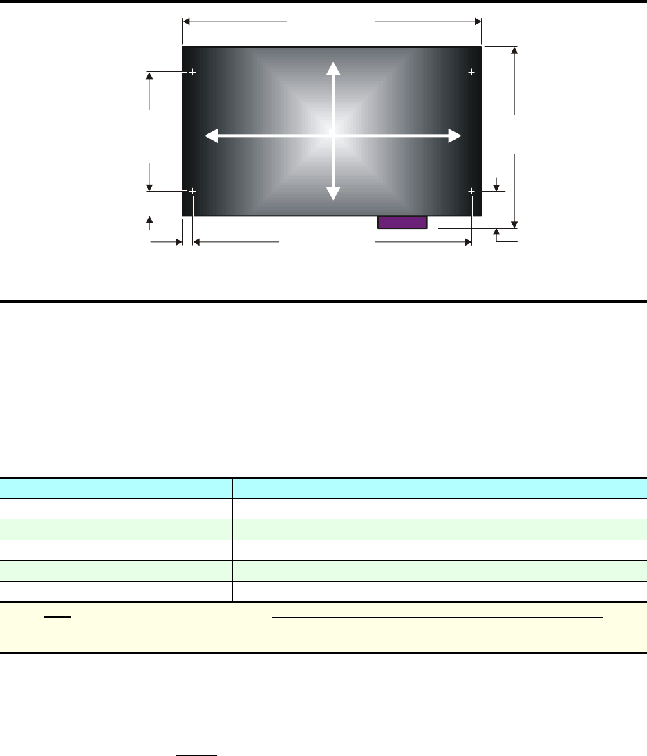
Site Readiness Planning
4-54 Sun Confidential: Internal Only 96257
Revision A
Raised-Floor Lateral Stability Ratings
In areas of high earthquake activity, the lateral stability of raised floors must be consid-
ered. Raised floors where VSM5 system equipment is installed must be able to resist the
horizontal-stress levels shown in Table 4-5.
Raised-Floor Panel Ratings
Raised floor panels must be able to resist a concentrated load of 454 kg (1000 lbs.) and a
rolling load of 181 kg (400 lbs.) anywhere on the panel with a maximum deflection of 2 mm
(0.08 in.). Perforated floor panels are not required for VSM5 system equipment, but if used
must comply with the same ratings.
Figure 4-3. VSM5-VTSS Cabinet Weight Distribution and Leveler Locations
97.40
(261)
109.72
(294)
75.01
(201)
84.34
(226)
14.98
(5.90)
(2X)
6.29 (2.725)
(2X)
6.29
(2.725)
(2X)
47.11
(18.55)
(2X)
77.1
(30.35)
92.1
(
36.26
)
77.59 (30.55)
(2X)
A504 02
6
X
X
Z
Z
Table 4-5. Raised Flooring Horizontal Force Chart
Seismic Risk Zone Horizontal Force (V) Applied at Top of Pedestal
1 13.5 kg / 29.7 lbs
2A 20.2 kg / 44.6 lbs
2B 26.9 kg / 59.4 lbs
340.4 kg / 89.1 lbs
4 53.9 kg / 118.8 lbs
Note: Note: Horizontal forces are based on the 1991 Uniform Building Code (UBC) Sections 2336 and 2337, and
assume minimum operating clearances for multiple VSM5 cabinets. Installations in areas not covered by the
UBC should be engineered to meet seismic code provisions of the local jurisdiction.
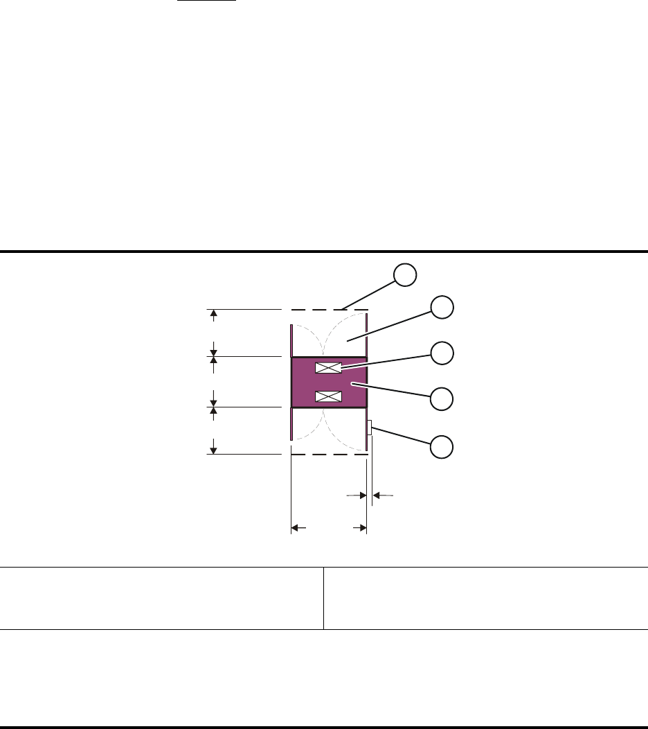
96257 Sun Confidential: Internal Only 4-55
Revision A
Site Evaluation – Internal Considerations
Raised-Floor Pedestal Ratings
Raised floor pedestals must be able to resist an axial load of 2268 kg (5000 lbs.). Where
floor panels are cut to provide service access, additional pedestals may be required to
maintain the loading capacity of the floor panel.
Physical Space Requirements
Floor space and layout requirements can differ for each VSM5 system configuration.
Figure 4-4 shows dimensions and recommended service clearances for a VSM5-VTSS
cabinet. Considerations for floor space layout may include, but are not limited to: available
space; required service clearances; intended equipment applications; equipment priority
assignments; equipment visibility from the host console; operator convenience; cable
lengths; and future expansion plans.
Figure 4-4. VSM5-VTSS Cabinet Dimensions for Physical Space Planning
1. Boundary of recommended service access area
2. Open radius of front and rear doors (4 total)
3. Cabinet
4. Openings for entry / exit of data and power cables
5. Front cover bezel (additional 6.35 cm (2.5 inches)
right-side clearance required to open door 90 degrees)
Notes:
• Metric dimensions are shown first (in centimeters), followed by English dimensions (in inches).
• Front and rear doors are shown in the open position to indicated dimensions required for service access.
• The VTSS does not require or provide side access; side covers are permanently attached and should not be re-
moved under normal circumstrances
3
A504 02
8
77.1 (30.34)
54.1 ( )21.3
6.35 (2.5
)
54.1 (21.3)
92.1
(36.24
)
2
4
5
3
1
Site Readiness Planning
4-56 Sun Confidential: Internal Only 96257
Revision A
This page is intentionally blank.

96257 Sun Confidential: Internal Only A-57
Revision A
A
Specifications and
Additional Information
This appendix provides specifications and additional information for the VSM5-VTSS.
Content includes:
•“Motherboard and FRU Interconnections – Side 0” on page A-58
•“Motherboard and FRU Interconnections – Side 1” on page A-59
•“Power Safety Grounding Diagram – Side 0” on page A-60
•“Power Safety Grounding Diagram – Side 1” on page A-61
•“Power System Diagram” on page A-62
•“Data Paths and Interfaces” on page A-63
•“Fiber Optic Cable Specifications” on page A-64
•“VShell Command Reference” on page A-64
•“Sample IOCP Gen for FICON Configuration” on page A-65
•“Virtual Tape Drive Mapping and Host Addressing” on page A-66
•“FRU Identifiers” on page A-67
•“Array Drive Module Status Descriptions” on page A-72
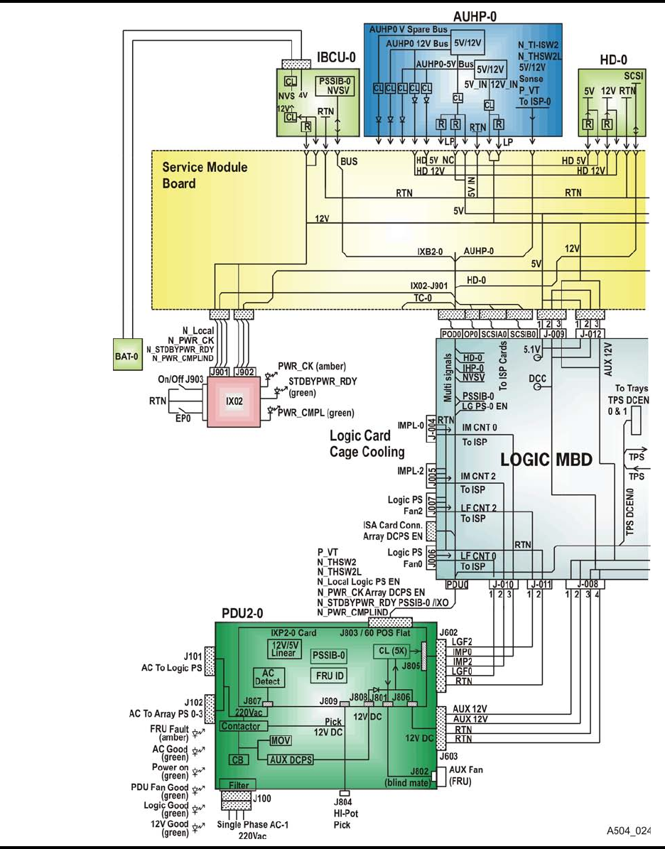
Specifications and Additional Information
A-58 Sun Confidential: Internal Only 96257
Revision A
■Motherboard and FRU Interconnections – Side 0
Figure A-1. VSM5-VTSS Motherboard and FRU Interconnections – Side 0
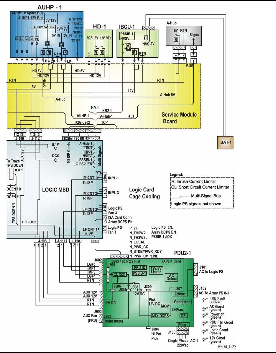
96257 Sun Confidential: Internal Only A-59
Revision A
Motherboard and FRU Interconnections – Side 1
■Motherboard and FRU Interconnections – Side 1
Figure A-2. VSM5-VTSS Motherboard and FRU Interconnections – Side 1
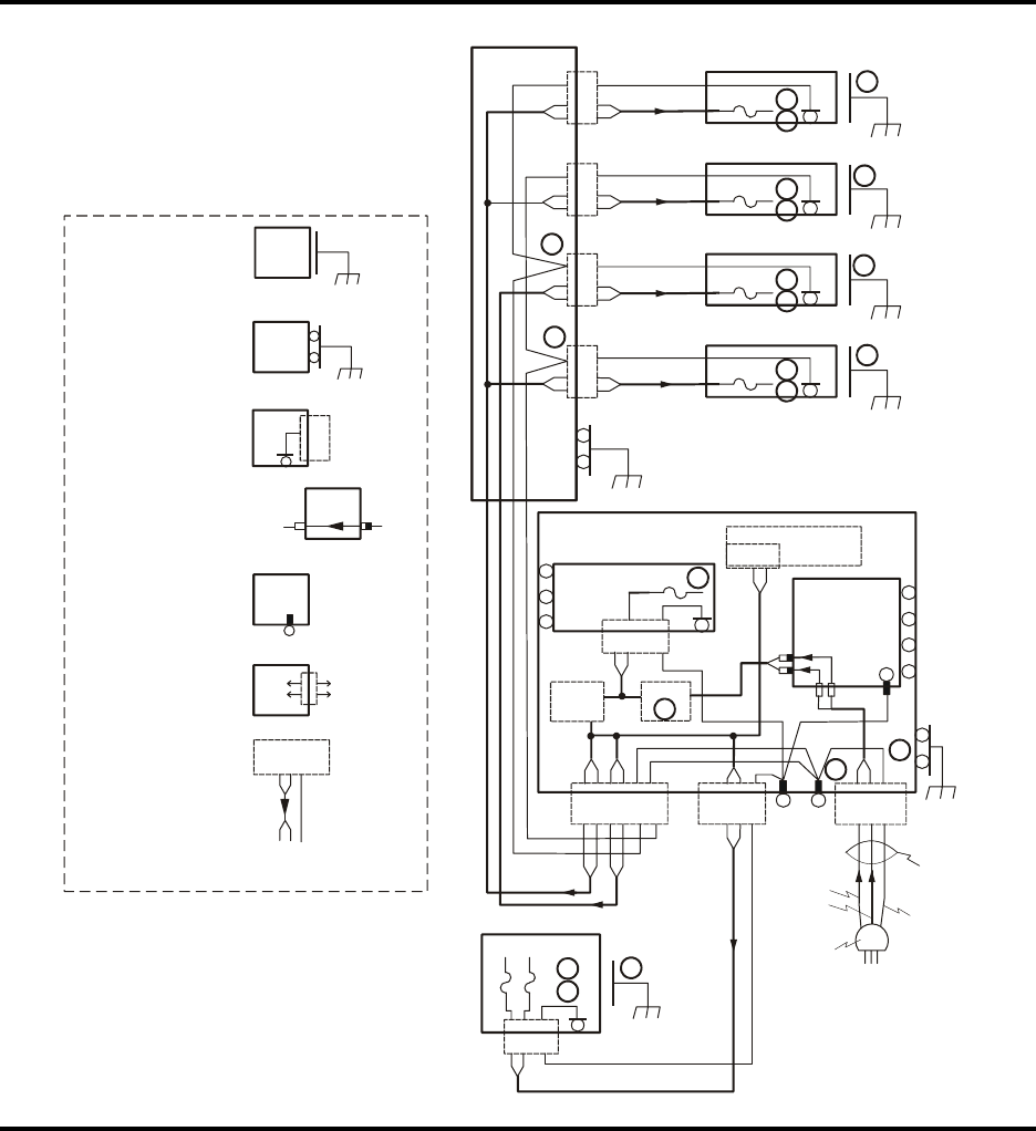
Specifications and Additional Information
A-60 Sun Confidential: Internal Only 96257
Revision A
■Power Safety Grounding Diagram – Side 0
Figure A-3. VSM5-VTSS Power Safety Grounding Diagram – Side 0
A504
_
022
6
7
6
7
6
7
Legend
FRU
FRU
FRU
FRU
FRU
Line
Filter
IEC 320
Frame
LNG
LNG
FRU grounded to
frame with incidental,
uncontrolled
metal-metal contact
Line and neutral
wires are shown
bused together
Direction of power
flow is indicated by
the arrow
Slide connections
in and out of line
filter.
AC
Load
Side
FRU chassis
grounded through
connector
Connector into FRU
with wires going in
and out
Stud making
electrical
contact to chassis
FRU grounded to
frame with two (2)
screws
2X
6-32
Frame
AC
Line
Side
ICE 320
Array PS-0
Power Strip 0 Not a Controlled
Connection for
Safety Purposes
#16 Pigtail
#16 Pigtail Array PS-2 Frame
6-32
6
7
6.3A(X2) 3
#16 Pigtail
#16 Pigtail
Array PS-4
Array PS-6
Frame
Frame
Frame
6-32
6-32
6-32
3
3
6.3A(X2)
6.3A(X2)
6.3A(X2)
9
9
#16
6-32
Frame
TBD
3
#16 Pigtail
6-32
3X PDU - 0
AUX-PS-0
IXP2-0
8
2A
J1 6-32
P807
#22
#16 Line Filter
#10 Studs
#12 #12
#12
#16
#16
Relay
K100
CB100
5
1
#10
4X
6-32
2X
6-32
#16
4
Frame
AC-0 to
Logic PS
AC-0 to
Array Ps’s
Mate-N-LOK IEC320 #10
Studs
AMP CPC
J102 J101 J100
Black or
Brown
Blue or
White
#10 Wire
Cable
Green/
Yellow
Russell-Stoll
3750 L N G
Single Phase
AC-0 Input Plug
Logic PS -0 Logic Card
Cage
#16 Cable
6-32 Frame
3
6
IEC320
15A 15A 7
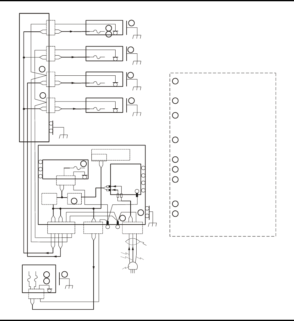
96257 Sun Confidential: Internal Only A-61
Revision A
Power Safety Grounding Diagram – Side 1
■Power Safety Grounding Diagram – Side 1
Figure A-4. VSM5-VTSS Power Safety Grounding Diagram – Side 1
A504_068
Array PS-1
Power Strip 1
#16 Pigtail
Not a Controlled
Connection for
Safety Purposes
#16 Pigtail
#16 Pigtail
#16 Pigtail
#16 Pigtail
Array PS-3
Array PS-5
Array PS-7
Frame
Frame
Frame
Frame
6-32
6-32
6-32
6-32
3
3
3
3
6
7
6.3A(X2)
6.3A(X2)
6.3A(X2)
6.3A(X2)
9
9
#16
6-32
Frame
TBD
6-32
3X PDU - 1
AUX-PS-1
IXP2-1
8
2A
J1
6-32
P807
#22
#16
Line Filter
#10 Studs
#12
#12
#12
#16
#16
Relay
K100
CB100
5
1
#16
#10
4
4X
6-32
2X
6-32
Frame
AC-1 to
Logic PS
AC-1 to
Array Ps’s
Mate-N-LOK IEC320 #10
Studs
AMP CPC
Black or
Brown
Blue or
White
#10 Wire
Cable
Green/
Yellow
Russell-Stoll
3750 L N G
Single Phase
AC-1 Input Plug
J102 J101 J100
#16 Cable
6-32 Frame
3
6
Logic PS -1
7
IEC320
15A 15A
Logic Card
Cage
The frame connection to the PDU chassis
must be made to the same panel that has the
grounded stud.
The array and logic DPCS’s are safety
grounded through the input AC connector.
There may be metal-metal contact between
DCPS chassis and machine frame. Frame
which is not controlled and can not serve as
a safety ground.
On PDU chassis, there is a dedicated nut
for incoming ground wire connection to
chassis stud.
CB100 = 30 rating. TBD delay curve
Both phases are fused in logic and array PS’s.
Logic PS fuse = 3AB, 250V, 15A, standard
delay curve
Array PS fuse = 3AG, 250V, 6.3A, slow-blow
delay curve
Only one phase is fused in AUX PS.
Ground connections to IEC-320 connectors in
power strips are double crimped
#16 AWG IN 0.250 fast-on tab connectors.
Notes
1
2
3
4
5
6
7
8
9
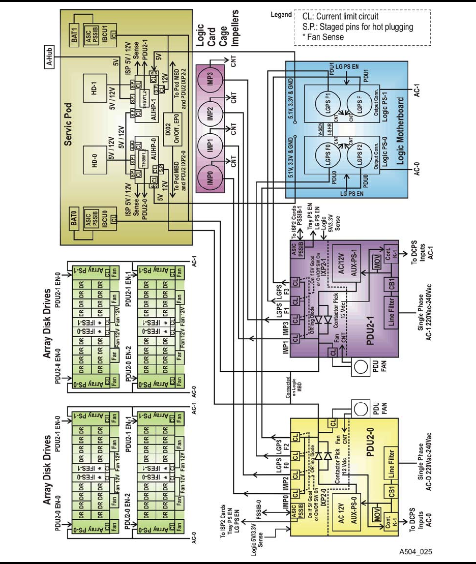
Specifications and Additional Information
A-62 Sun Confidential: Internal Only 96257
Revision A
■Power System Diagram
Figure A-5. VSM5-VTSS Power System Diagram
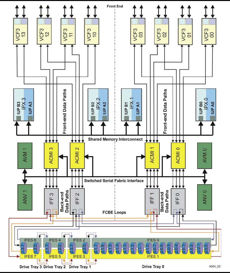
96257 Sun Confidential: Internal Only A-63
Revision A
Data Paths and Interfaces
■Data Paths and Interfaces
Figure A-6. VSM5-VTSS Data Paths and Interfaces

Specifications and Additional Information
A-64 Sun Confidential: Internal Only 96257
Revision A
■Fiber Optic Cable Specifications
■VShell Command Reference
Table A-1. Fiber Optic Cable Specifications
Optical Performance Specification
Attenuation 1.0 dB/km @ 1300 nm
Bandwidth 500 MHz/km @ ≤ 2 km
Handling Characteristics Specification
Pulling Strength 27.2 kg (60 lbs.)
Crush Resistance 650 Newtons/cm (371 ft-lbs/in2)
Minimum Bend Radius 96 mm (3.74 in.)
Cable Weight 59.7 kg/100 m (401 lbs./1000 ft.)
Bending Cycles 100 at minimum bend radius
Physical Environment -16o C to +32o C (3.2o F to 89.6o F)
Note: Abbreviations key: C = centigrade; dB = decibel(s); F = Fahrenheit; ft. = foot / feet; in2 = inch(es) squared; km
= kilometer(s); lb(s). = pound(s); m = meter(s); MHz = megahertz; mm = millimeter(s); nm = nanometer(s)
Table A-2. VShell Command Reference
Command Meaning / Description
Status avail Displays Subsystem Availability screen
Status subsystem Displays Subsystem Configuration and Status screen
Status cfes Lists current Composite Failure Events (CFEs)
Status ispdrive Lists status of ISP hard drives and shown which SRL are preloaded
Status adrives prod Lists all HDAs assigned in production arrays
Status adrives spares Lists all HDAs assigned as global spares
Status adrives unavail Lists all HDAs unavailable for use (including U.B.—unavailable broken)
Status interfaces Displays Subsystem Interface Status screen
Status channels Displays Channel Configuration Status screen
Ecu Preloads EC upgrade microcode
Hicstat $ Displays and downloads hic_stat.dia file to a selected current drive
Realtime Lists DOP Status field messages in real time; useful for monitoring system IML
Showsrl Lists the system release level (SRL) that is currently running on the VTSS
State <name>Downloads the named state save file to a selected current drive
Allstate $ Downloads all state saves and associated files to a selected current drive
Help Displays online help file for all commands; click [Enter] to close
Help <command>Displays online help file with information about the named command

96257 Sun Confidential: Internal Only A-65
Revision A
Sample IOCP Gen for FICON Configuration
■Sample IOCP Gen for FICON Configuration
Figure A-7. Sample IOCP Gen for FICON Configuration
>> NOTE: The example below shows an IOCP gen for a single MVS host connected to a VSM5 through
FICON directors.
ESCD4C CHPID PATH=(20,70), TYPE=FC, SWITCH=4C
ESCD4C CHPID PATH=(21,71), TYPE=FC, SWITCH=4D
ESCD4C CHPID PATH=(30,80), TYPE=FC, SWITCH=4E
ESCD4C CHPID PATH=(31,81), TYPE=FC, SWITCH=4F
CU1 CNTLUNIT CUNUMBER=001
PATH=(20,21,30,31,70,71,80,81),
LINK=(D0,D4,D0,D4,D4,D0,D4,D0),
UNIT=3490,CUADD=0,
UNITADD=((00,16))
STRING1 IODEVICE ADDRESS=(0500,16),
CUNUMBER=(001),
UNIT=3490,
UNITADD=00,STADET=Y
CU2 CNTLUNIT CUNUMBER=002
PATH=(20,21,30,31,70,71,80,81),
LINK=(D0,D4,D0,D4,D4,D0,D4,D0),
UNIT=3490,CUADD=1,
UNITADD=((00,16))
STRING2 IODEVICE ADDRESS=(0510,16),
CUNUMBER=(002),
UNIT=3490,
UNITADD=00,STADET=Y
.
.
.
CU15 CNTLUNIT CUNUMBER=015
PATH=(20,21,30,31,70,71,80,81),
LINK=(D0,D4,D0,D4,D4,D0,D4,D0),
UNIT=3490,CUADD=E,
UNITADD=((00,16))
STRING15 IODEVICE ADDRESS=(05E0,16),
CUNUMBER=(015),
UNIT=3490,
UNITADD=00,STADET=Y
CU16 CNTLUNIT CUNUMBER=016
PATH=(20,21,30,31,70,71,80,81),
LINK=(D0,D4,D0,D4,D4,D0,D4,D0),
UNIT=3490,CUADD=F,
UNITADD=((00,16))
STRING16 IODEVICE ADDRESS=(05F0,16),
CUNUMBER=(016),
UNIT=3490,
UNITADD=00,STADET=Y

Specifications and Additional Information
A-66 Sun Confidential: Internal Only 96257
Revision A
■Virtual Tape Drive Mapping and Host Addressing
A VSM5-VTSS can be configured with up to 256 virtual tape drives (VTDs). During VTSS
installation, all 256 available VTDs are mapped as shown in Table A-3 below. Mapping of
all available VTDs is required by VTSS microcode, and applies whether the VTDs are ulti-
mately defined or undefined.
Table A-3. Mapping Parameters for 256 Virtual Tape Drives (VTDs)
Sequential Device
Numbers Parameters Sequential Device
Numbers Parameters
0 - 15
VCU0
DEV 0-255
FDID 00-0F
CUADD=0
128 -143
VCU8
DEV 0-255
FDID 80-8F
CUADD=8
16 - 31
VCU1
DEV 0-255
FDID 10-1F
CUADD=1
144 -159
VCU9
DEV 0-255
FDID 90-9F
CUADD=9
32 - 47
VCU2
DEV 0-255
FDID 20-2F
CUADD=2
160 -175
VCUA
DEV 0-255
FDID A0-AF
CUADD=A
48 - 63
VCU3
DEV 0-255
FDID 30-3F
CUADD=3
176 -191
VCUB
DEV 0-255
FDID B0-BF
CUADD=B
64 -79
VCU4
DEV 0-255
FDID 40-4F
CUADD=4
192 -207
VCUC
DEV 0-255
FDID C0-CF
CUADD=C
80 -95
VCU5
DEV 0-255
FDID 50-5F
CUADD=5
208 -223
VCUD
DEV 0-255
FDID D0-DF
CUADD=D
96 -111
VCU6
DEV 0-255
FDID 60-6F
CUADD=6
224 -239
VCUE
DEV 0-255
FDID E0-EF
CUADD=E
112 -127
VCU7
DEV 0-255
FDID 70-7F
CUADD=7
240 -255
VCUF
DEV 0-255
FDID F0-FF
CUADD=F

96257 Sun Confidential: Internal Only A-67
Revision A
FRU Identifiers
■FRU Identifiers
Table A-4. VSM5-VTSS FRU Identifiers
Physical
Location FRU
Common Name FRU
Silkscreen FRU Number
(Hex) FRU Number
(Decimal) FRU Location ID
(Unit.Tray.Slot)
Power Distribution Units
CU Front Tray 0 Power Distribution Unit 0 PDU2-O 4E 78 CU.0.PDU0
CU Front Tray 0 Power Distribution Unit 1 PDU2-1 4F 79 CU.0.PDU1
Inside PDU0 PDU0 Internal Fan FAN 0 3C1 961 CU.0.FAN0
Inside PDU1 PDU1 Internal Fan FAN 1 3C2 962 CU.0.FAN0
Maintenance Pod
CU MPOD Tray Battery Charger Unit IBCU-0 4C 76 CU.3.BCU0
CU MPOD Tray Battery Charger Unit IBCU-1 4D 77 CU.3.BCU1
CU MPOD Tray ISP Hard Drive HD2-0 384 900 CU.3.HD0
CU MPOD Tray ISP Hard Drive HD2-1 385 901 CU.3.HD1
CU MPOD Tray 5v/12v Power Supply AUHP-0 388 904 CU.3.AUHP0
CU MPOD Tray 5v/12v Power Supply AUHP-1 389 905 CU.3.AUHP1
CU MPOD Tray A-Hub Card
Faceplate Assembly ?? 386 902 CU.3.???
CU MPOD Tray Battery Pack BAT-0 394 916 CU.3.BAT0
CU MPOD Tray Battery Pack BAT-1 395 917 CU.3.BAT1
CU Front Tray 3 Power Control Panel PPNL 387 903 CU.3.PPNL
DC Power Supplies
CU Rear Tray 1 Logic Power Supply 0 LPS2-0 1A 26 CU.1.LPS0
CU Rear Tray 1 Logic Power Supply 1 LPS2-1 1B 27 CU.1.LPS1
DA Rear Tray 0 Array Power Supply 0 APS-0 94 148 DA.0.APS
DA Rear Tray 1 Array Power Supply 1 APS-1 95 149 DA.1.APS
DA Rear Tray 2 Array Power Supply 2 APS-2 A8 168 DA.2.APS
DA Rear Tray 3 Array Power Supply 3 APS-3 A9 169 DA.3.APS
DA Rear Tray 4 Array Power Supply 4 APS-4 F8 248 DA.4.APS
DA Rear Tray 5 Array Power Supply 5 APS-5 F9 249 DA.5.APS
DA Rear Tray 6 Array Power Supply 6 APS-6 10C 268 DA.6.APS
DA Rear Tray 7 Array Power Supply 7 APS-7 10D 269 DA.7.APS

Specifications and Additional Information
A-68 Sun Confidential: Internal Only 96257
Revision A
Logic Motherboard and Cards
CU Rear CU Motherboard ACMB 1C 28 CU.1.ACMB
CU Front Tray1 VCF3 Card 0 VCF00 5 5 CU.1.VCF00
CU Front Tray1 VCF3 Card 1 VCF01 6 6 CU.1.VCF01
CU Front Tray1 VCF3 Card 2 VCF02 8 8 CU.1.VCF02
CU Front Tray1 VCF3 Card 3 VCF03 9 9 CU.1.VCF03
CU Front Tray1 VCF3 Card 4 VCF10 16 22 CU.1.VCF10
CU Front Tray1 VCF3 Card 5 VCF11 15 21 CU.1.VCF11
CU Front Tray1 VCF3 Card 6 VCF12 13 19 CU.1.VCF12
CU Front Tray1 VCF3 Card 7 VCF13 12 18 CU.1.VCF13
CU Front Tray1 IPX5 Card 0 IPX0 1 1 CU.1.IPX0
CU Front Tray1 IPX5 Card 1 IPX1 B 11 CU.1.IPX1
CU Front Tray1 IPX5 Card 2 IPX2 E 14 CU.1.IPX2
CU Front Tray1 IPX5 Card 3 IPX3 18 24 CU.1.IPX3
CU Front Tray1 ISP3A Card 0 ISP0 1F 31 CU.1.ISP0
CU Front Tray1 ISP3A Card 1 ISP1 20 32 CU.1.ISP1
CU Rear Tray 1 ISP Clock Battery PB-0 398 920 CU.1.PB0
CU Rear Tray 1 ISP Clock Battery PB-1 399 921 CU.1.PB1
CU Front Tray 2 IFF2 Card 0 IFF0 2B 43 CU.2.IFF0
CU Front Tray 2 IFF2 Card 1 IFF1 29 41 CU.2.IFF1
CU Front Tray 2 IFF2 Card 2 IFF2 36 54 CU.2.IFF2
CU Front Tray 2 IFF2 Card 3 IFF3 34 52 CU.2.IFF3
CU Front Tray 2 ACMI3 Card 0 ACMI0 2C 44 CU.2.ACMI0
CU Front Tray 2 ACMI3 Card 1 ACMI1 28 40 CU.2.ACMI1
CU Front Tray 2 ACMI3 Card 2 ACMI2 37 55 CU.2.ACMI2
CU Front Tray 2 ACMI3 Card 3 ACMI3 33 51 CU.2.ACMI3
CU Front Tray 2 ANV3 Card 0 ANV0 25 37 CU.2.ANV0
CU Front Tray 2 ANV3 Card 1 ANV1 26 38 CU.2.ANV1
CU Front Tray 2 AVM4 or AVM16 Card 0 AVM0 23 35 CU.2.AVM0
CU Front Tray 2 AVM4 or AVM16 Card 1 AVM1 24 36 CU.2.AVM1
CU Rear CU Frame FRM 1D 29 CU.1.FRM
Table A-4. VSM5-VTSS FRU Identifiers (Continued)
Physical
Location FRU
Common Name FRU
Silkscreen FRU Number
(Hex) FRU Number
(Decimal) FRU Location ID
(Unit.Tray.Slot)

96257 Sun Confidential: Internal Only A-69
Revision A
FRU Identifiers
Logic Power Supply Fans
CU Rear Tray 1 LPS0 Fan 0 FAN-0 3BD 957 CU.1.FAN0
CU Rear Tray 1 LPS0 Fan 1 FAN-1 3BE 958 CU.1.FAN1
CU Rear Tray 1 LPS1 Fan 2 FAN-2 3BF 959 CU.1.FAN2
CU Rear Tray 1 LPS1 Fan 3 FAN-3 3C0 960 CU.1.FAN3
Card Cage Impellers
CU Rear Tray 2 Card Cage Impeller 0 IMP0 38A 906 CU.2.IMP0
CU Rear Tray 2 Card Cage Impeller 1 IMP1 38B 907 CU.2.IMP1
CU Rear Tray 2 Card Cage Impeller 2 IMP2 38C 908 CU.2.IMP2
CU Rear Tray 2 Card Cage Impeller 3 IMP3 38D 909 CU.2.IMP3
Physical Array Disk Drive Tray 0
DA Rear
Physical Drive Tray 0
(Logical Tray DA0.0)
Array Drive Module 0 DRV0 8C 140 DA.0.DRV0
Array Drive Module 1 DRV1 8D 141 DA.0.DRV1
Array Drive Module 2 DRV2 8E 142 DA.0.DRV2
Array Drive Module 3 DRV3 8F 143 DA.0.DRV3
Array Drive Module 4 DRV4 90 144 DA.0.DRV4
Array Drive Module 5 DRV5 91 145 DA.0.DRV5
Array Drive Module 6 DRV6 92 146 DA.0.DRV6
Array Drive Module 7 DRV7 93 147 DA.0.DRV7
DA Rear Tray 0 Drive Tray 0 Fan FAN-0 44C 1100 DA.0.FAN
DA Front Tray 0 Tray Interface Monitor IFES 0 51 81 DA.0.IFES
Physical Array Disk Drive Tray 1
DA Rear
Physical Drive Tray 1
(Logical Tray DA0.1)
Array Drive Module 0 DRV0 96 150 DA.1.DRV0
Array Drive Module 1 DRV1 97 151 DA.1.DRV1
Array Drive Module 2 DRV2 98 152 DA.1.DRV2
Array Drive Module 3 DRV3 99 153 DA.1.DRV3
Array Drive Module 4 DRV4 9A 154 DA.1.DRV4
Array Drive Module 5 DRV5 9B 155 DA.1.DRV5
Array Drive Module 6 DRV6 9C 156 DA.1.DRV6
Array Drive Module 7 DRV7 9D 157 DA.1.DRV7
DA Rear Tray 1 Drive Tray 1 Fan FAN-1 44D 1101 DA.1.FAN
DA Front Tray 1 Tray Interface Monitor IFES 1 52 82 DA.1.IFES
Table A-4. VSM5-VTSS FRU Identifiers (Continued)
Physical
Location FRU
Common Name FRU
Silkscreen FRU Number
(Hex) FRU Number
(Decimal) FRU Location ID
(Unit.Tray.Slot)

Specifications and Additional Information
A-70 Sun Confidential: Internal Only 96257
Revision A
Physical Array Disk Drive Tray 2
DA Rear
Physical Drive Tray 2
(Logical Tray DA0.2)
Array Drive Module 0 DRV0 A0 160 DA.2.DRV0
Array Drive Module 1 DRV1 A1 161 DA.2.DRV1
Array Drive Module 2 DRV2 A2 162 DA.2.DRV2
Array Drive Module 3 DRV3 A3 163 DA.2.DRV3
Array Drive Module 4 DRV4 A4 164 DA.2.DRV4
Array Drive Module 5 DRV5 A5 165 DA.2.DRV5
Array Drive Module 6 DRV6 A6 166 DA.2.DRV6
Array Drive Module 7 DRV7 A7 167 DA.2.DRV7
DA Rear Tray 2 Drive Tray 2 Fan FAN-2 44E 1102 DA.2.FAN
DA Front Tray 2 Tray Interface Monitor IFES 2 55 85 DA.2.IFES
Physical Array Disk Drive Tray 3
DA Rear
Physical Drive Tray 3
(Logical Tray DA0.3)
Array Drive Module 0 DRV0 AA 170 DA.3.DRV0
Array Drive Module 1 DRV1 AB 171 DA.3.DRV1
Array Drive Module 2 DRV2 AC 172 DA.3.DRV2
Array Drive Module 3 DRV3 AD 173 DA.3.DRV3
Array Drive Module 4 DRV4 AE 174 DA.3.DRV4
Array Drive Module 5 DRV5 AF 175 DA.3.DRV5
Array Drive Module 6 DRV6 B0 176 DA.3.DRV6
Array Drive Module 7 DRV7 B1 177 DA.3.DRV7
DA Rear Tray 3 Drive Tray 3 Fan FAN-3 44F 1103 DA.3.FAN
DA Front Tray 3 Tray Interface Monitor IFES 3 56 86 DA.3.IFES
Physical Array Disk Drive Tray 4
DA Rear
Physical Drive Tray 4
(Logical Tray DC0.0)
Array Drive Module 0 DRV0 F0 240 DA.4.DRV0
Array Drive Module 1 DRV1 F1 241 DA.4.DRV1
Array Drive Module 2 DRV2 F2 242 DA.4.DRV2
Array Drive Module 3 DRV3 F3 243 DA.4.DRV3
Array Drive Module 4 DRV4 F4 244 DA.4.DRV4
Array Drive Module 5 DRV5 F5 245 DA.4.DRV5
Array Drive Module 6 DRV6 F6 246 DA.4.DRV6
Array Drive Module 7 DRV7 F7 247 DA.4.DRV7
DA Rear Tray 4 Drive Tray 4 Fan FAN-4 450 1104 DA.4.FAN
DA Front Tray 4 Tray Interface Monitor IFES 4 53 83 DA.4.IFES
Table A-4. VSM5-VTSS FRU Identifiers (Continued)
Physical
Location FRU
Common Name FRU
Silkscreen FRU Number
(Hex) FRU Number
(Decimal) FRU Location ID
(Unit.Tray.Slot)

96257 Sun Confidential: Internal Only A-71
Revision A
FRU Identifiers
Physical Array Disk Drive Tray 5
DA Rear
Physical Drive Tray 5
(Logical Tray DC0.1)
Array Drive Module 0 DRV0 FA 250 DA.5.DRV0
Array Drive Module 1 DRV1 FB 251 DA.5.DRV1
Array Drive Module 2 DRV2 FC 252 DA.5.DRV2
Array Drive Module 3 DRV3 FD 253 DA.5.DRV3
Array Drive Module 4 DRV4 FE 254 DA.5.DRV4
Array Drive Module 5 DRV5 FF 255 DA.5.DRV5
Array Drive Module 6 DRV6 100 256 DA.5.DRV6
Array Drive Module 7 DRV7 101 257 DA.5.DRV7
DA Rear Tray 5 Drive Tray 5 Fan FAN-5 451 1105 DA.5.FAN
DA Front Tray 5 Tray Interface Monitor IFES 5 54 84 DA.5.IFES
Physical Array Disk Drive Tray 6
DA Rear
Physical Drive Tray 6
(Logical Tray DC0.2)
Array Drive Module 0 DRV0 104 260 DA.6.DRV0
Array Drive Module 1 DRV1 105 261 DA.6.DRV1
Array Drive Module 2 DRV2 106 262 DA.6.DRV2
Array Drive Module 3 DRV3 107 263 DA.6.DRV3
Array Drive Module 4 DRV4 108 264 DA.6.DRV4
Array Drive Module 5 DRV5 109 265 DA.6.DRV5
Array Drive Module 6 DRV6 10A 266 DA.6.DRV6
Array Drive Module 7 DRV7 10B 267 DA.6.DRV7
DA Rear Tray 6 Drive Tray 6 Fan FAN-6 452 1106 DA.6.FAN
DA Front Tray 6 Tray Interface Monitor IFES 6 57 87 DA.6.IFES
Physical Array Disk Drive Tray 7
DA Rear
Physical Drive Tray 7
(Logical Tray DC0.3)
Array Drive Module 0 DRV0 10E 270 DA.7.DRV0
Array Drive Module 1 DRV1 10F 271 DA.7.DRV1
Array Drive Module 2 DRV2 110 272 DA.7.DRV2
Array Drive Module 3 DRV3 111 273 DA.7.DRV3
Array Drive Module 4 DRV4 112 274 DA.7.DRV4
Array Drive Module 5 DRV5 113 275 DA.7.DRV5
Array Drive Module 6 DRV6 114 276 DA.7.DRV6
Array Drive Module 7 DRV7 115 277 DA.7.DRV7
DA Rear Tray 7 Drive Tray 7 Fan FAN-7 453 1107 DA.7.FAN
DA Front Tray 7 Tray Interface Monitor IFES 7 58 88 DA.7.IFES
Table A-4. VSM5-VTSS FRU Identifiers (Continued)
Physical
Location FRU
Common Name FRU
Silkscreen FRU Number
(Hex) FRU Number
(Decimal) FRU Location ID
(Unit.Tray.Slot)
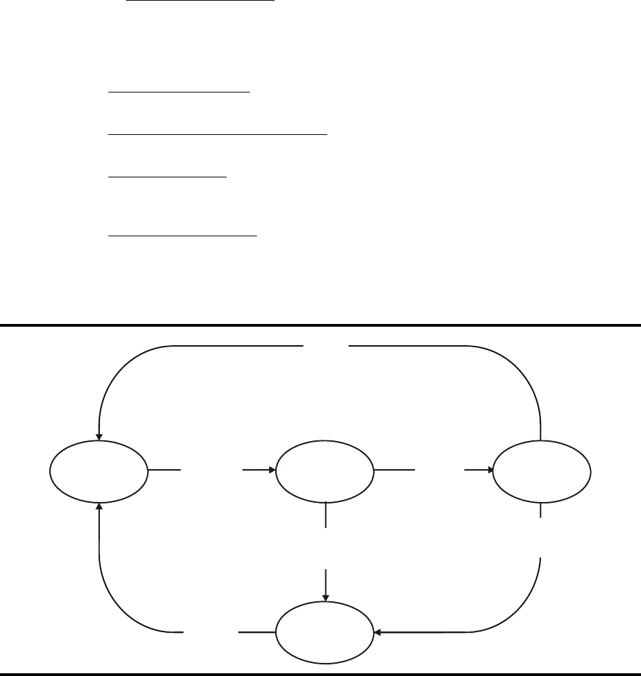
Specifications and Additional Information
A-72 Sun Confidential: Internal Only 96257
Revision A
■Array Drive Module Status Descriptions
The Disk Drive / Array Status screen displays the status of each VTSS array drive as a
two-character code. The first character defines the partition a specific drive is associated
with; the second characther defines the current state of the drive. For example, a status of
‘P.A’ indicates that a drive is in production partition (‘P’) and active (‘A’). The four types of
drive partitions are:
• Production Partition (P) – contains drives that are usable for storing and retrieving pro-
duction data
• Media Acceptance Test Partition (M) – a holding partition; contains drives that can be as-
signed to the spares partition
• Spares Partition (S) – a holding partition; contains drives that can be used primarily for
three functions: array formation; drive reconstruction; and draining an array, an entire ar-
ray unit, an entire drive tray, or a single drive.
• Unavailable Partition (U) – any slot or drive not under control of the user, including slots
that do not have an array drive installed, slots that contain array drives but are not active,
and slots that contain broken array drives.
Figure A-8. Array Drive Module States and Relationships
A504
_
015
Allocate
Spares Form
Array
Drive
Failure
New / Replacement
Drives
Drain
Production
MAT
Unavailable
Drive
Failure
Spares

96257 Sun Confidential: Internal Only A-73
Revision A
Array Drive Module Status Descriptions
Table A-5. Array Drive Module Status Descriptions
Drive Module Status Status Code Meaning/Description
Production Partition
Production: Active P.A (PA) Drive is active.
Production: Broken P.B (PB) Drive is inactive and marked as broken. After its data is moved to
a spare, broken drive is removed from Production partition and
put in ‘Unavailable: Broken’ (U.B) state.
Production: Copy P.C (PC) Drive is receiving data from drain of Production drive.
Production: Draining P.D (PD) Drive is being drained.
Production:
Initialize Array P.I (PI) Drive is part of array initialization process.
Production:
Pending Drain P.P (PP)
Drive is awaiting drain, but drain cannot start because:
• Broken-to-spare data reconstruction is in progress
• Another drive in the array is being drained
• The number of spares is inadequate (occurs if number of
spares was reduced after drain request was accepted).
Production:
Reconstruction P.R (PR) Data from broken drive is being reconstructed on spare drive,
which moves to ‘P.A’ state when reconstruction finishes.
Production:
Unknown Drive State P.? (P?)
Drive is broken but cause is unknown. Usually means data is be-
ing reconstructed to a spare, but may indicate other unknown
state. After its data is moved, the broken drive moves from the
Production partition to an ‘Unavailable: Broken’ (U.B) state.
Media Acceptance Test (MAT) Partition
MAT: Active M.A (MA) Drive is active and available for allocation as a spare.
MAT: Fenced M.F (MF) Drive is fenced because GFR function is in progress.
MAT: Drive Not Ready M.? (M?) Drive is not active due to diagnostic error. After failure is isolated,
broken drive is removed from MAT partition and put in ‘Unavail-
able: Broken’ (U.B) state.
Spares Partition
Spare: Active S.A (SA) Drive is available to form arrays, reconstruct data, or receive da-
ta from drain operation.
Spare: Fenced S.F (SF) Drive is fenced for drive test.
Spare: Pending Drain S.P (SP) Drive is awaiting drain pending completion of drive test.
Spare: Drive Failure S.? (S?) Drive is not active for unknown reason (possible failure). After
failure is isolated, broken drive is removed from Spares partition
and put in ‘Unavailable: Broken’ (U.B) state.
Unavailable Partition
Unavailable: Broken U.B (UB) Drive is broken.
Unavailable: Isolated U.I (UI) Drive is isolated from the SSA loop configuration.
Unavailable:
No Active Drive Module U.N (UN) No active drive is sensed in this slot.
Unavailable:
Slot Not Installed U.S (US) No drive is installed in this slot.
Specifications and Additional Information
A-74 Sun Confidential: Internal Only 96257
Revision A
This page is intentionally blank.

96257 Sun Confidential: Internal Only B-75
Revision A
B
FICON Channel Extension
Guidelines
This appendix provides information about FICON channel extensions for the VSM system.
Content includes:
•“Definition of Terms” on page B-76
•“General Channel Extension Considerations”, including:
-“Understand Channel Extension Performance Limitations” on page B-77
-“Channel Extenders Are Invisible to Other Devices” on page B-77
-“Channel Extenders Can Cause Timing Problems” on page B-77
-“Channel Extenders Can Insert Fake I/O Errors” on page B-77
-“Avoid RECLAIMs and DRAINs on Channel-Extended RTDs” on page B-77
-“Avoid RECALLs on Channel-Extended RTDs” on page B-77
-“Avoid Syncsort Apps That Use Long Chains on Channel-Extended VTDs” on page B-
77
•“FICON Topologies” on page B-78
•“Placement of Extension Equipment” on page B-78
•“Interoperability Testing” on page B-78
•“FICON Channel Extension – Sample Configurations” on page B-79
•“McData/CNT Channel Extension Interoperability”, including:
-“Set Buffer-to-Buffer Credits at Director Ports” on page B-81
-“Set Extension-Attached Director Ports to Fixed Speeds” on page B-81
-“Set Extension Ports to Fixed Speeds When Extending a VTSS-to-VTSS Channel Link
(CLINK) or a VTSS-to-RTD Link” on page B-82
-“ISL Failover Is Supported Only in Shuttle Mode” on page B-82
-“Avoiding Host Protocol Timeouts” on page B-82
-“Performance Considerations” on page B-82
•“Cisco Systems Channel Extension Interoperability” on page B-83.
Note: Always consult your selected vendor’s release documentation for their extension
products, and guidelines for proper application of those products.

FICON Channel Extension Guidelines
B-76 Sun Confidential: Internal Only 96257
Revision A
■Definition of Terms
The following terms are used in this appendix:
• Front-end – any equipment between a host and a VTSS
• Back-end – any equipment between a VTSS and RTD
• Channel extension – a configuration of equipment that exceeds the maximum distance
allowed by native FICON protocol, implemented by adding a pair of channel extenders.
• Channel extender – a piece of equipment that can lengthen the maximum distance al-
lowed between two pieces of FICON-capable equipment. Channel extenders are used in
pairs, usually with a WAN network between them. Some channel extenders have
FICON director/switch capabilities, and hence are also labeled as FICON switches.
• FICON director or FICON switch – a piece of equipment that is capable of acting like an
electronic ‘patch panel’. Directors are used to reduce the number of cables required to
achieve connectivity between multiple pieces of equipment. Note that some vendors sell
FICON directors/switches that also can function as channel extenders (when appropriate
cards have been added).
• Cascading switches – a hardware configuration which includes at least one FICON direc-
tor/switch connected to another FICON director/switch. In the IBM native FICON proto-
col, cascading can involve no more than two switches; however, most switch vendors al-
low more than two switches in a cascaded configuration.
•ISL
– inter-switch sink; a link between two switches. ISLs can be channel-extended.
•Direct attach
– any connection between two pieces of equipment that does not go
through a FICON director/switch. The connection could, however, still include channel
extenders (which are invisible to the FICON protocol).
•RTD
– Real Tape Drive; a physical tape drive linked to a VTSS box, as opposed to a host.
Note that if a FICON director/switch is used between the tape drive and VTSS, the drive
could function as a RTD at one point in time, and as a conventional tape drive at another
time; this would require varying the drive offline from VTCS and online to MVS.
• Conventional tape drive – a tape drive linked to a host, as opposed to a VTSS box. Note
that if a FICON director/switch is used between the tape drive and VTSS, the drive could
function as a conventional tape drive at one point in time, and as a RTD at another time;
this would require varying the drive offline from MVS and online to VTCS.
•Cluster
– a pair of VTSS boxes connected by one or more CLINKs. Depending on the di-
rection of the CLINKs, a cluster can be uni-directional or bi-directional. Clustering is used
to provide hardware fallback in case one of the VTSS boxes becomes inoperative. VTVs
can be replicated between the two VTSS boxes in normal mode (over the CLINKs), al-
lowing one box to take over from the other in case of an outage.
•CLINK
– Cluster LINK; a connection between two VTSS boxes in a cluster. Each CLINK
allows data to flow in only one direction. For bi-directional clustering, at least one CLINK
in each direction must be used. A CLINK connection between two VTSS boxes can in-
clude FICON directors/switches and channel extenders.
•VTD
– Virtual Tape Drive; a virtual (as opposed to physical) tape drive that exists within a
VTSS, as defined by the VTCS (Virtual Tape Control System) host software. A VTD is a
transport in a VTSS that emulates a physical 3490E tape drive to a MVS system. Data
that are ‘written’ to a VTD actually are written to the disk buffer (VTSS). A VTSS has 64
VTDs that perform virtual mounts of VTVs.

96257 Sun Confidential: Internal Only B-77
Revision A
General Channel Extension Considerations
■General Channel Extension Considerations
Understand Channel Extension Performance Limitations
Channel extension usually involves using a WAN (wide-area network), which possibly op-
erates at slower-than-FICON speeds. At the very least, the addition of channel extenders
will cause additional overhead, and will slow down tape I/O processing.
Channel Extenders Are Invisible to Other Devices
By its nature, channel extension must look to end devices (hosts, switches, VTSSs, and/or
RTDs) as if those were connected to each other without channel extenders; hence, chan-
nel extenders are invisible to FICON devices. Neither software on the host (HSC/VTCS)
nor microcode in a VTSS or RTD can sense the existence of a channel extender.
Channel Extenders Can Cause Timing Problems
Since channel extenders can cause delays, adding channel extenders to a configuration
that works may cause I/O timeouts or other I/O problems. If channel extenders are used
for both tape and disk I/O, the disk I/O can cause further delays for tape I/O, for example.
Channel Extenders Can Insert Fake I/O Errors
Some channel extension products attempt to streamline tape I/O in various ways, includ-
ing simulating responses from tape drives or VTSSs. On occasion, a channel extender will
encounter a problem, which must be reported back to the issuer of the tape I/O. Since a
channel extender is invisible to end devices, it has no way to report errors itself; instead, a
channel extender will report a fake I/O error coming from a RTD or VTSS, when the chan-
nel extender was actually the source of the problem. These types of errors can be very dif-
ficult to diagnose, and may require personnel from multiple vendors for resolution.
Avoid RECLAIMs and DRAINs on Channel-Extended RTDs
Most current channel extension products will attempt to streamline tape write I/O but not
read I/O. This means users should avoid long operations that require large amounts of
read I/O over channel extenders. There are many different back-end and front-end sce-
narios to consider, but one that should definitely be avoided is doing DRAIN and RE-
CLAIM operations over channel extenders. DRAINs and RECLAIMs tend to perform many
tape read I/Os on input MVC cartridges (as well as tape wirtes to output MVC cartridges).
Avoid RECALLs on Channel-Extended RTDs
Most current channel extension products will attempt to streamline tape write I/O but not
read I/O. This means users should avoid long operations that require large amounts of
read I/O over channel extenders. RECALL operations cause data to be copied from a
MVC cartridge mounted on a RTD back into a VTSS box. If the path between a VTSS and
RTD includes channel extenders, such a recall may be very slow. Automatic recalls (which
are triggered by a job on the mainframe needing data not available in a VTSS) especially
can hold up critical work on the mainframe.
Avoid Syncsort Apps That Use Long Chains on Channel-Extended VTDs
Some Syncsort applications that use long chains (specifically when using sort work files
allocated to virtual tape) will not run when using channel extenders between the host and
the VTSS (i.e., a remote VTSS), due to protocol timeouts that can occur from WAN de-
lays. The application should be evaluated, and dedicated conventional tape drives should
be considered for Syncsort applications. If VSM is required, consider running the Syncsort
application on local VTSS, rather than a remote (channel-extended) VTSS. Alternatively, if
possible, the best option is to configure shorter chains.

FICON Channel Extension Guidelines
B-78 Sun Confidential: Internal Only 96257
Revision A
■FICON Topologies
See “Placement of Extension Equipment” below to determine proper placement of exten-
sion equipment for the following FICON topologies:
1. Host-to-VTSS (front-end link to VTDs)
a. direct-attach connection
b. single FICON director/switch connection
c. cascaded directors/switches connection
2. VTSS-to-RTD (back-end link to RTDs)
a. direct-attach connection
b. single FICON director/switch connection
c. cascaded directors/switches connection
3. VTSS-to-VTSS (CLINKs)
a. direct-attach connection
b. single FICON director/switch connection
c. cascaded directors/switches connection
4. Host-to-conventional tape drive (no VTSS nor VSM involved)
a. direct-attach connection
b. single FICON director/switch connection
c. cascaded directors/switches connection
■Placement of Extension Equipment
VSM allows many different ways of connecting hosts with VTSS boxes and RTDs, with or
without FICON directors/switches. The number of combinatons and permutations is too
large to list here. Use the sample configurations shown on the following pages as a guide-
line for where to place channel extension equipment.
■Interoperability Testing
Supported directors and configurations for VSM-VTSS systems with channel extensions
are listed in the Interop Tool on the Sun Sales Support website at https://extranet
.stortek.com/interop/interop.
The Interop Tool provides connectivity information for all currently supported products sold
through Sun, regardless of whether the product is Sun branded or third-party branded.
While the tool does validate compatibility, it does not validate the final configuration, the
system, or whether the configuration will perform in the end user’s environment. Consult
with Sun support personnel to validate all configurations before ordering equipment.
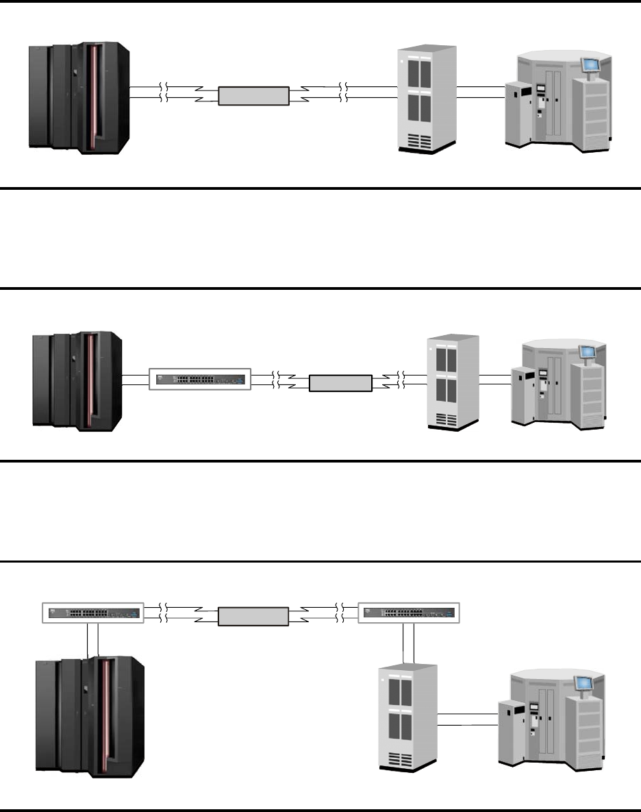
96257 Sun Confidential: Internal Only B-79
Revision A
FICON Channel Extension – Sample Configurations
■FICON Channel Extension – Sample Configurations
Figure B-1. Host-to-VTSS Channel Extension – Direct Attachment
Tape Silo
with RTDs
Channel
Extender
VTSS
A502
_
048
z
/OS
Host
Figure B-2. Host-to-VTSS Channel Extension – Behind Single FICON Switch / Director
FICON
Director/Switch
Tape Silo
with RTDs
A502
_
049
z
/OS
Host VTSS
Channel
Extender
Figure B-3. Host-to-VTSS Channel Extension – Between Cascaded FICON Switches / Directors
A502
_
05
0
Tape Silo
with RTDs
Channel
Extender
VTSS
z/OS
Host
FI
CO
N
Director/Switch FI
CO
N
Director/Switch
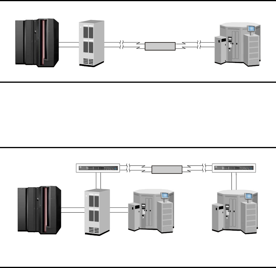
FICON Channel Extension Guidelines
B-80 Sun Confidential: Internal Only 96257
Revision A
Figure B-4. VTSS-to-RTD Channel Extension – Direct Attachment
A502
_
051
Tape Silo
with RTDs
Channel
Extender
VTSS
z
/OS
Host
Figure B-5. VTSS-to-RTD Channel Extension – Between Cascaded FICON Switches / Directors
z/OS
Host
Local
VTSS
Local
Tape Silo
A502
_
052
Remote
Tape Silo
with RTDs
Channel
Extender
FI
CO
N
Director/Switch FI
CO
N
Director/Switch
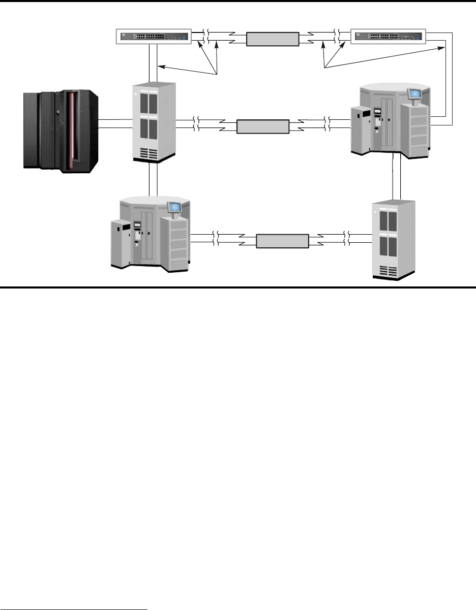
96257 Sun Confidential: Internal Only B-81
Revision A
McData/CNT Channel Extension Interoperability
■McData/CNT Channel Extension Interoperability
The following interoperability and configuration information and guidelines apply when us-
ing McData/CNT USD-X and Edge3000 channel extenders with a VSM-VTSS.
Set Buffer-to-Buffer Credits at Director Ports
In FICON fabric topology, configure buffer-to-buffer (BB) credits on all director ports that
are part of all channel-extended end-to-end paths to ‘extended distance’, i.e., ≥ 60 BB
credits. This includes host ports, CU ports, and ISL1 ports that carry I/O on a channel-ex-
tended path, regardless of which link is physically extended. For example, consider a sin-
gle director configuration with three CHPIDs configured to perform I/O with two CU ports,
where one CU port is channel-extended. In this case, four director ports should have their
BB credits set to ‘extended distance’: Each of the three F_Ports attached to the three
hosts, and the F_Port attached to the extension equipment that extends to the CU port.
Set Extension-Attached Director Ports to Fixed Speeds
When channel extension is added to a FICON link, the result is two FICON links which are
coupled by the two channel extension chassis through a WAN. The link speed setting on
at least one side of the pair of FICON links must be set to a fixed speed to avoid exposure
to an issue where the link may not initialize once a fibre/SFP2 cable is attached, or where
the link may not reinitialize after a loss of synchronization during operations.
Figure B-6. VTSS-to-VTSS Channel Extension – Between Cascaded FICON Switches / Directors
Channel
Extender
CLINKs CLINKs
Channel
Extender
A502
_
053
z/OS
Host
Local
Clustered
VTSS
Remote
Clustered
VTSS
Local
Tape Silo
Remote
Tape Silo
with RTDs
Channel
Extender
FI
CO
N
Director/Switch FI
CO
N
Director/Switch
1. Inter-switch link; the fibre channel link providing connectivity between two switches
2. Short form factor pluggable connectors
FICON Channel Extension Guidelines
B-82 Sun Confidential: Internal Only 96257
Revision A
The FICON directors on the supported list provide a port configuration option for link
speed. The VSM port runs in auto-speed mode (currently unconfigurable). The recom-
mendation is to set all FICON director ports attached to extension equipment to a fixed
speed, and to set the attached extension ports to a fixed speed, as follows:
• Set the FICON director port to ‘1Gbps-ONLY’ for attachment to the USD-X channel ex-
tender. Also set the speed of the attached USDX port to ‘1Gbps-ONLY’.
• Set the FICON director port to ‘2Gbps-ONLY’ for attachment to the Edge3000 channel
extender. Also set the speed of the attached Edge3000 port to ‘2Gbps-Only’.
Note: Setting the FICON director port to ‘1Gbps-ONLY’ for the Edge3000 channel ex-
tender attachment is also valid when the WAN link in 1Gbps Ethernet. In this con-
figuration, also set the attached Edge3000 port to ‘1Gbps-ONLY’.
Set Extension Ports to Fixed Speeds When Extending a VTSS-to-VTSS
Channel Link (CLINK) or a VTSS-to-RTD Link
When channel extension is added to a FICON link, the result is two FICON links which are
coupled by the two channel extension chassis through a WAN. The link speed setting on
at least one side of the pair of FICON links must be set to a fixed speed to avoid exposure
to an issue where the link may not initialize once a fibre/SFP cable is attached, or where
the link may not reinitialize after a loss of synchronization during operations.
McData channel extension equipment on the supported list provides a port configuration
option for link speed, which defaults to auto-speed. McData service personnel may per-
form this configuration change to a fixed speed.
The recommendation is to set a least one attached extension port per extended link to a
fixed speed, as follows:
• Set the speed of the attached USD-X chanel extender port to ‘1Gbps-Only’.
• Set the speed of the attached Edge3000 channel extender port to ‘2Gbps-Only’.
Note: Setting the attached Edge3000 port to ‘1Gbps-Only’ is also valid when the WAN
link in 1Gbps Ethernet.
ISL Failover Is Supported Only in Shuttle Mode
McData does not support ISL failover when the extension equipment is configured for
FICON emulation. If extension equipment is configured in FICON shuttle mode, then ISL
failover can be used. Due to distance limitations, shuttle mode is seldom used.
Avoiding Host Protocol Timeouts
Host protocol timeouts may occur due to WAN delays that increase the time for the VTSS
to process multiple outstanding ‘CU busy’ signals. To avoid these timeouts:
• Vary on no more than 16 devices over a channel-extended path to a single VTSS port
• Configure the USD-X or Edge3000 channel extender to support 32 simultaneous emula-
tions by setting the number of emulation control blocks (ECBs) to 32.
Performance Considerations
Consult McData recommendations regarding performance considerations and modes of
operation (i.e., emulation versus shuttle). McData channel extenders emulate write com-
mands, and use shuttle mode (WAN ‘pass-through’) for read commands. When planning
for channel extension, consider the job mix (specifically, the read workload) in combination
with performance requirements, as performance may be significantly affected with the
shuttle mode over certain distances.

96257 Sun Confidential: Internal Only B-83
Revision A
Cisco Systems Channel Extension Interoperability
■Cisco Systems Channel Extension Interoperability
The following interoperability and configuration information and guidelines apply when us-
ing Cisco Systems channel extension equipment with a VSM-VTSS.
Note: This qualification is for distances up to 200km without any performance penalty.
Cisco is planning a performance improvement beyond the current 200km limit,
which will be tested by Sun once that code level is delivered. No timeline has been
established for completion of the >200km distance qualification.
Note: These guidelines apply to VSM4-VTSS models VSMA-734, VSMB-734, VSMC-
734, and VSMD-734. Tests are pending to ensure the guidelines are applicable for
model VSME-734 (VSM4 ‘lite’), and for VSM5-VTSS models VSMB-465, VSMC-
465, and VSMD-465.
• Supported Cisco channel extenders:
- MDS 9506 (up to 200km)
- MDS 9509 (up to 200km)
• Mandatory code base levels:
- MDS 9506/9509 – 2.1.2b
- VSM4 – D01.02.02.04 or higher
Customers should consult fabric vendor guidelines and DWDM1 vendor guidelines to as-
sure valid configurations (i.e., distances, fibre and SFP cable types, settings, etc.).
1. Dense wavelength division multiplexer, e.g. the McData FSP 2000
FICON Channel Extension Guidelines
B-84 Sun Confidential: Internal Only 96257
Revision A
This page is intentionally blank.

96257 Sun Confidential: Internal Only C-85
Revision A
Glossary
A
AC. Alternating current. Current in which the direction is
reversed, or alternated, 60 times per second (50 times
per second in some countries). Contrast with direct cur-
rent.
acceptance test. A formal test done by a system end-
user to determine if a system works according to specifi-
cations and should be accepted.
access density. A measure of I/O activity; the number of
I/O operations per gigabyte of functional capacity per
second.
access privileges. The extent to which a user may op-
erate a system resource on a host, network, or file serv-
er. In many cases, permission to access a host, network,
or file server, view its contents, and modify or create files
is limited by a system administrator to maintain security.
ACMI. VSM-VTSS cache memory interface card.
AC power redundancy (ACPR). An AC power system
that provides dual AC power sources to prevent power
interruptions and loss of access to data. If one power
source fails, the other (redundant) source supplies all
power to a subsystem until the failed unit is replaced.
ACS. Automated Cartridge System. Also library or tape
library. A system that automatically mounts cartridges in
tape drives in response to requests from host software.
ACSLS. Automated Cartridge System Library Software;
Automated Cartridge System Library (Unix) Server.
actuator-level buffer (ALB). Solid-state memory asso-
ciated with an actuator in a storage device. In VSM,
ALBs minimize rotational latency in disk drives and allow
non-synchronous data transfer between the front-end
cache and back-end disk array drives.
address. (1) A hexadecimal number that represents an
identifying location for a device or an area of storage; for
example, a memory register, disk sector, or network
node. (2) An identifier for a communication port. (3) The
act of communicating with a storage device.
ADC. Analog-to-digital converter.
ADT. Automatic data transfer.
AFO. Americas Field Operations. Acronym for all Sun
StorageTek U.S./Canada field operations.
AIX. Advanced Interactive eXecutive. The IBM version of
Unix.
ALB. See actuator-level buffer.
algorithm. A detailed, ordered set of instructions for
solving a problem. When used in computer program-
ming, term refers to instructions given to a computer.
allocated array cylinder. An array cylinder that contains
current or non-current user data.
alphanumeric. A system of notation which utilizes al-
phabetic letters, numbers, and special characters.
AME. Advanced Manufacturing Engineering. At Sun
StorageTek, an engineering group that manufactures
product prototype machines, typically through the EPE
phase of a product development cycle.
AMT. Automatic migration threshold. User-defined per-
centage values that determine when virtual tape volume
migration begins and ends. VTV migration begins when
the VTSS buffer reaches the high AMT and ends when
the buffer reaches or falls below the low AMT. These
thresholds apply to all VTSSs.
analog. A means of representing data in continuously
variable physical quantities, in contrast to digital repre-
sentation of data in discrete units (binary digits 1 and 0).
Analog systems handle information that is represented
by continuous change and flow, such as voltage or cur-
rent. Contrast with digital.
ANSI. American National Standards Institute. An organi-
zation that establishes procedures by which accredited
organizations create and maintain voluntary industry
standards in the U.S., including those for the computer
industry. ANSI is the U.S. member of the International
Electrotechnical Commission (IEC) and the International
Organization for Standardization (ISO).
ANV. VSM-VTSS nonvolatile memory storage card.
APL. Assembly parts list.
application. A software program designed to perform a
specific task or group of tasks, such as word processing,
communications, or database management.
array. A group of storage devices controlled in such a
way as to provide higher data transfer rates, higher data
availability, and data redundancy. An array is typically
treated as a single volume by a host operating system.
array architecture. A class of magnetic disk architec-
ture in which several physical devices emulate (typically)
fewer virtual devices of (typically) higher capacity and
performance.
array cylinder. A collection of all physical cylinders in a
dual-redundancy array with the same physical address
(CC, **). VSM allocates back-end space in units of array
cylinders, which are either free or allocated.
array track. A collection of all physical tracks in a dual-
redundancy array that have the same physical track ad-
dress (CC, HH).
ASAL. Alternate Sector Assignment List.
ASCII. American Standard Code for Information Inter-
change. A protocol for displaying characters and trans-
ferring data between computers and associated equip-
ment. ASCII codes are numbers from 0 to 255. Numbers
0 to 32 are non-printing control codes; 33 to 127 are for
letters and punctuation; 128 to 255, called extended
characters, can be used for a variety of purposes, but
are most commonly used for accented letters, graphics,
and other special characters.
ASIC. Application-specific integrated circuit. A custom-
ized microchip designed for use on a particular circuit
board, or for a specific application.
ASM. Application Storage Manager. A Sun StorageTek
high-performance file system with hierarchical storage
management (HSM) functionality, available for Solaris
and NT platforms.
ASU. Advanced Site Unit. Hardware component of the
Sun StorageTek Service Delivery Platform (SDP) remote
support software.

C-86 Sun Confidential: Internal Only 96257
Revision A
asynchronous. Not synchronized; not occurring at regu-
lar, predetermined intervals. Asynchronous transmis-
sions send one data character at a time, at irregular in-
tervals, rather than in one steady stream; a start bit and a
stop bit notify the receiver when the transmission begins
and ends. Contrast with synchronous.
ATA. Advanced Technology Attachment. Official name
for the disk drive interface standard commonly known as
Integrated Drive Electronics (IDE).
ATM. Asynchronous transfer mode. A networked tech-
nology based on transferring data cells or packets of a
fixed size.
attenuation. (1) The tendency for a signal to become
weaker and more distorted as its transmission distance
increases. (2) The loss or reduction of signal magnitude,
normally measured in decibels (dB).
AVMn. VTSS volatile memory storage cards; AVM4
cards have 4 MB capacity; AVM16 cards 16 MB.
B
back-end storage. The data storage portion of a stor-
age subsystem. In VTSS, the disk arrays.
background. A mode of operation where tasks are per-
formed on a low-priority basis to minimize the impact on
overall system performance. Contrast with foreground.
backup. The process of producing a copy of a data set
for purposes of possible future recovery. Although tape is
the most common storage medium for backups, disk is
equally usable, although more expensive.
bandwidth. The amount of data that can be sent through
a network connection, measured in bits per second
(bps). High bandwidth allows fast transmission or high-
volume transmission.
base memory. Solid state memory in a controller that
stores the functional track directory (FTD) and other in-
ternal tables required for subsystem operations. Base
memory is not part of user-available cache.
battery backup unit (BBU). A system of batteries that
automatically supplies power to nonvolatile storage if AC
power is disrupted, to protect nonvolatile cache data. A
VTSS battery backup system has redundant batteries
that provide at least 72 hours of backup power.
battery charger unit (BCU). A VTSS device that contin-
uously charge a battery used to provide backup power.
baud rate. The transmission rate of a serial data stream
over communications lines, most often (but not always)
measured in bits per second (bps). Baud is a measure of
the number of signal-state changes per second; for ex-
ample, voltage or frequency changes.
BBU. See battery backup unit.
BCU. See battery charger unit.
BER. Bit error rate.
beta test. The second test phase for new software (after
Alpha testing), wherein software is made available to us-
ers who evaluate it in what is expected to be typical op-
erating conditions.
binary. A numbering system which has 2 as its base and
uses 0s and 1s for its notation. Binary code is used by
computers because it works well with digital electronics
and Boolean algebra. In binary (base 2) numbering, the
number one is written as 1, the number two is written as
10, and the numbers three to ten are written as 11, 100,
101, 110, 111, 1000, 1001, 1010, etc.
bit. A binary digit of 0 or 1; a unit of computer information
equivalent to the result of a choice between two alterna-
tives (yes/no, on/off, etc.). Contrast with gigabit, kilobit,
megabit.
block. Also called a packet. (1) A contiguous section of
bits considered as a whole, especially in memory. On a
disk, a block is the data in one sector; in a modem data
transfer, a block is the bits between checksums. (2) A
group of bits transmitted as a unit and treated as a unit of
information; usually consists of its own starting and end-
ing control delimiter, a header, text to be transmitted, and
check characters at the end used for error correction.
Block sizes are usually a multiple of 512 bytes.
BOM. Bill of material.
bps. Bits per second. The number of bits of data that can
be transmitted in one second.
Bps. Bytes per second. The number of bytes of data that
can be transmitted in one second.
browser. A text- or graphic-based client program, such
as Netscape Navigator or Microsoft Internet Explorer,
that allows users to read hypertext documents on the
World Wide Web, and navigate between them.
buffered subsystem. A storage subsystem that pro-
vides separation between front- and back-end opera-
tions so data transfer synchronization is not required.
bus. A parallel electrical pathway, usually part of a circuit
board, that both connects and is shared by the parts of a
computer system (CPU, support circuitry, memory,
cards, etc.). Typically, the lines in a bus are dedicated to
specific functions, such as control, addressing, and data
transfer.
byte. A group of adjacent binary digits (bits) that a com-
puter processes as a single unit, or ‘word.’ Frequently
written as an eight-digit binary number or two-digit hexa-
decimal number. One letter of the alphabet in ASCII
code takes one byte. Contrast with gigabyte, kilobyte,
megabyte.
C
CAB. Customer Advisory Board. At Sun StorageTek, a
group of customers who advise a corporate design team
about the features and functionality they would like to
have engineered into upcoming products.
cache. A block of memory that temporarily collects and
retains data before it is sent to a host or destaged to
back-end disk arrays, allowing quicker retrieval of fre-
quently-used data to improve overall system perfor-
mance. In VSM, all data is accessed through cache.
cache fast write (CFW). In VTSS, a write command
function wherein host data is written directly to volatile
cache memory without using nonvolatile storage (NVS),
and then is subsequently scheduled for destaging to
back-end disk arrays.
CAM. Central Archive Manager.
CAP. Cartridge access port of a Sun StorageTek library
unit.
CBT. Computer-based training.
CCR. Channel command retry. A channel procedure, ini-
tiated by a controller, that causes a channel command to
be repeated without breaking the command chain.
CCW. Channel command word.
CD-R. Compact Disc-Recordable.

96257 Sun Confidential: Internal Only C-87
Revision A
CD-ROM. Compact Disc Read-Only Memory. An optical
disc that may contain computer data, audio data, graph-
ics, and other information, and is interchangeable be-
tween different types of computers. Storage capacity is
typically about 680 MB per disc.
CDS. Control data set. An HSC database containing all
configuration and volume information, used by host soft-
ware to control functions of automated libraries.
CEI. Configured end item.
CFE. Composite Failure Event. In VTSS, a structure
formed for each discrete failure domain.
CFT. Controlled field test.
change journal. In VSM, the record of changes to the
functional track directory (FTD) that is kept in nonvolatile
storage (NVS) and is then written to the disk arrays
(VTSS). VSM uses the change journal to reconstruct the
FTD in the event of a failure.
channel. (1) A point-to-point link whose primary task is
to transport data from one point to another. (2) A path for
transfer of data and control information between a disk
drive and array controller. (3) A device that connects a
host and main storage with the I/O control units.
channel image. A software image that logically presents
itself as a single physical channel, regardless of how the
physical connection is made. Each channel image ap-
pears to be an independent single physical channel, al-
though all channel images on a specific I/O interface
share the same facilities and physical paths. A VSM5-
VTSS presents up to 16 control unit images to each of 1
to 28 host systems.
channel interface. Controller circuitry that attaches host
channels.
check0. An error condition detected within a VTSS pro-
cessor card that affects the integrity of the processor. If a
second check 0 is detected within the same processor
during recovery, the processor hard-stops (a ‘double
check 0’ condition), making the operation or condition
unrecoverable by the failing processor.
check1. An error condition that affects a control bus or
shared memory bus but leaves processor cards function-
al. Check1 may affect all processors on a bus, since the
bus is locked until the condition is cleared.
check2. An error condition detected in the non-proces-
sor logic cards.
checksum. A value that accompanies data transferred
between points to ensure the data is transferred correct-
ly. Checksum is computed by adding up the bytes or
words of a data block. On the receiving end, checksum is
computed based on the data received and compared
with the value that was sent with the data. If the two
numbers match, the data is considered to be correct.
CHPID. Channel-path identifier. A value assigned to an
installed channel path that provides for its discrete recog-
nition by a VTSS.
circuit breaker. A switch that automatically interrupts an
electrical circuit when there is an overload of current or
other abnormal condition.
CKD. See count-key data.
client. A system which is able to operate independently
but has some degree of dependence on another system.
Frequently refers to computers on a LAN. A client is a re-
cipient of services in a client/server application. Clients
can be workstations, PCs, or other servers.
client/server. A system architecture in which one or
more programs (clients) request computing or data ser-
vices, such as data storage, processing, or transmission,
from another program (server).
clink. clustered link. An ESCON port used to link a mas-
ter and slave VTSS in a clustered configuration.
clock speed. In storage systems, the frequency at which
the system clock oscillates, as measured in MHz. The
faster the clock, the more quickly the system can trans-
mit information.
clustering. (1) In VSM, the process of writing a virtual
tape volume (VTV) onto two discrete VTSSs. (2) A tech-
nique for configuring two or more servers as a single pro-
cessing system using software and hardware to allow
sharing of storage, processing, and other resources un-
der a single management domain, thereby providing
greater data accessibility and higher reliability.
CM. Configuration Management. (1) Identification and
management of physical product configurations through
documentation, records, and data. (2) An organization
within Sun responsible for applying these disciplines
through a formal EC process.
cold boot. The act of switching a computer, storage sys-
tem, etc. Completely off, then switching it back on again.
Contrast with warm boot.
cold swap. To remove and replace a system component
(typically one such as a logic board that has no redun-
dant backup) after system operations have been stopped
and power has been disabled. Contrast with hot swap.
collected free space. Array cylinders that are collected
and completely free of user data.
collocation. A process that attempts to keep all data be-
longing to a single client node on a minimal number of
sequential-access media volumes within a storage pool.
Used to minimize the number of volumes that must be
accessed when a large amount of data must be restored.
command line interface. A user interface in which com-
mands are keyed onto a command line instead of
through a Graphical User Interface. Contrast with GUI.
compaction. The elimination of inter-record gaps nor-
mally associated with count-key data DASD that allows
less disk storage space to be used, reducing net capaci-
ty load in VTSS units.
compression. The process of encoding data using algo-
rithms so that it uses less storage space and/or increas-
es the rate, or speed, of data transmission.
Configuration Control Document (CCD). A Sun docu-
ment which defines model numbers, family ID codes,
feature codes, part numbers, etc. for a specific product,
and which identifies the configured end items (CEIs)
available for use in the product.
Configuration Status Monitor (CSM). In VTSS, a part
of the Failure Management System (FMS) that monitors
FRU configurations in the controller, performs FRU vali-
dation, and coordinates diagnostic fencing.
controlled power-down (CPD). An orderly sequence of
steps that shuts off AC power to a system without jeopar-
dizing customer data.
controller. A system control module or storage control
unit. Also called a control module or control unit. See al-
so disk array controller.
control region. VTSS data path control. Hardware in a
multipath controller that is associated with a data path
and which transfers data between the cache and disk ar-
rays and between cache and host channel(s).

C-88 Sun Confidential: Internal Only 96257
Revision A
control unit address. The base channel address to
which a control unit can respond.
conversion. A process that changes the basic capability
of a unit in a system and may be a disruptive, requiring a
customer to turn over use of the unit to a CSE. Conver-
sions may require special tools and higher-level skills of
a technical specialist. Contrast with upgrade.
count-key data (CKD). A recording format that writes
variable-length records. Contrast with fixed-block archi-
tecture.
CPAT. Corporate Product Acceptance Testing.
CPD. Central parts depot.
CPD. See controlled power-down.
CRC. See Customer Resource Center.
CRU. Customer-replaceable unit. Any item, module, or
unit on a system that a customer can replace without as-
sistance from a CSE.
CSA. Canadian Standards Association. A group serving
industry, government, and consumers which develops
product testing and certification standards and codes.
The Canadian counterpart of Underwriters Laboratories.
CSE. See Customer Service Engineer.
CSL. Cartridge scratch loader; cartridge stacker/loader.
CSL. See Customer Services Logistics.
CSM. See Configuration Status Monitor.
CSR. Control Status Register.
CSRC. A Sun StorageTek internal tool managed by the
NPDC that allows remote connection, operator panel ac-
cess, and remote file download capability for virtual disk
systems including VTSS.
CTR. Cache track recovery.
CTS. Corporate Technical Standard(s).
Customer Resource Center (CRC). A Sun StorageTek
website (www.support.stortek.com) that provides re-
sources including product documentation, tools and ser-
vices, and customer training information.
Customer Service Engineer (CSE). A technical engi-
neer who interacts with the end-user customers and is
responsible for fixing product problems and maintaining
product performance in customer accounts.
Customer Service Manager (CSM). A member of the
Sun StorageTek management team with first-line techni-
cal management responsibility for addressing problems
in customer accounts.
Customer Services Logistics (CSL). An organization
within Sun StorageTek responsible for coordinating deliv-
ery of spare parts to field depots worldwide.
cyclic redundancy check (CRC). A check performed
on data to see if an error has occurred in the transmit-
ting, reading, or writing of data.
D
DAC. See disk array controller.
DACD. Disk array controller display. FRU designation for
a VTSS local operator panel.
DASD. Direct-access storage device. (1) A storage de-
vice (typically a magnetic disk) in which data access
times are effectively independent of the location of the
data on the device. Conversely, in a serial-access stor-
age device (e.g., a magnetic tape), data must be access-
ed serially, such that data at the end of the tape spool
take much longer to access than data on the tape which
is passing immediately over the read/write head. (2) A
device in which the media is always available to the
read/write head without requiring mounting by an exter-
nal agent.
data compression. See compression.
data striping. The process of writing large blocks of data
across multiple drives and array groups to enhance data
protection capabilities.
data transfer rate. The speed at which data can be
transferred. Measured in bits per second (bps) for a mo-
dem, and in megabytes per second (MBps) for a hard
drive or fiber channel.
database. A collection of data arranged for ease and
speed of retrieval.
dB. Decibel.
DBU. Disk buffer utilization. The ratio of used to total
VTSS buffer capacity.
DC. Direct current. An electric current flowing in one di-
rection only. Contrast with alternating current.
DCN. Document Change Notice.
DDR. Defect discovery rate.
DDR. Dynamic device reconfiguration.
DDSR. Deleted Data Space Release. A VTSS ExPR
software function that informs a controller when function-
al volume datasets or minidisks are deleted, so that
physical disk space occupied by deleted data can imme-
diately become free space, thereby reducing DBU.
decibel (dB). In data transmission terms, a unit that
measures the ratio of the difference in power between
two electric signals.
decompress. To restore a compressed file to its original
size.
dedicated connection. In an ESCD, a connection be-
tween two ports that is not affected by information in link
frames. A dedicated connection restricts the ports from
communicating with other ports, and appears as one
continuous link.
deinstallation. Physically disconnecting a subsystem
with the intent of removing it from a customer site. Con-
trast with relocation.
destage. In VSM, the non-synchronous write of new or
updated data from cache or nonvolatile storage (NVS) to
the VTSS disk arrays.
Detailed Manufacturing Instruction. A document con-
taining a step-by-step description of the correct way to
assemble an item, including illustrations if necessary.
device. A single physical HDA.
device reconstruction. A VTSS automatic background
function that recreates and rewrites data from a failed
device to a spare device using the functional track recov-
ery (FTR) facility.
DFE. Distributed Fabric Element.
DFT. Direct field transfer.
Diagnostic Manager (DMGR). In VTSS, a facility that
administers, controls, and coordinates all diagnostic ac-
tivity within the VTSS environment through the diagnos-
tic submonitors (DSMs).

96257 Sun Confidential: Internal Only C-89
Revision A
digital. Information stored in binary form that a computer
recognizes. For computing use, text, graphics, and
sound are stored as digital bits represented by a 0 or 1.
Contrast with analog.
dimmed text. Dimmed or grayed-out text that appears
on a GUI menu and indicates an option is unavailable
because the system is not in the mode to use that func-
tion, or because software for that function is not installed.
Available options are typically displayed in undimmed
black text.
director. A logical entity that interfaces host channels to
a disk device. See also multipath storage director.
disk array. See dual-redundancy disk array.
disk array capacity. Formatted physical capacity of an
array, exclusive of capacity on redundancy/parity drives
or spare drives.
disk array controller. In VTSS, a control unit that imple-
ments storage management functions and provides in-
terface intelligence between hosts or network devices
and VTSS arrays.
disk drive. An electromagnetic mechanical device that
provides physical data storage on magnetic disk media.
DLF. See Download Facility.
DLT. Digital Linear Tape.
DMA. Direct Memory Access.
DMGR. See Diagnostic Manager.
DNS. Domain Name Server.
download. To receive files or data from one storage de-
vice or computer to another. Contrast with upload.
Download Facility (DLF). A VTSS facility that formats
event log data and connects to a RRC PC to offload
event log and MIM information as directed by the VTSS
PSA facility and subsystem internal timers.
drain. A process that gradually moves data stored from
an individual drive, drive array, or entire array unit to al-
low for eventual nondisruptive deinstallation of the
drive(s) or unit.
drive reconstruction. See device reconstruction.
driver. A software routine that controls or regulates a
hardware device.
DSP. Digital signal processor.
dual copy. A function of VTSS nonvolatile storage that
maintains two functionally identical copies of designated
disk volumes in a logical subsystem, and automatically
updates both copies each time a write operation is is-
sued to a logical volume.
dual-redundancy disk array. In VSM, a logical grouping
of physical disk storage devices on a VTSS. In an array
five disk drives are reserved for user data, and two are
used for redundancy/parity data. Dual-redundancy ar-
rays allow for real time automatic recovery of data on up
to two failed devices within an array.
duplex. Bidirectional; a two-fiber or two-element cable
that provides two-way data transmission, i.e., it can si-
multaneously send and receive data. Contrast with sim-
plex.
duplexing. In VSM, the process of writing a virtual tape
volume (VTV) on two discrete multi-volume cartridges
(MVCs).
Dynamic Configuration. A VTSS feature that allows
channel interfaces and up to 1024 functional volumes to
be defined and/or altered. Allows the functional configu-
ration of a VTSS to be determined by user requirements
rather than by available physical devices.
Dynamic Director. A VTSS feature that allows dynamic
switching of ESCON director links between the VTSS
and RTDs for optimum system performance.
dynamic mapping. A VTSS mapping technique that dy-
namically alters the correspondence between a function-
al track and its location on physical devices, thereby
avoiding ‘update-in-place’, a major performance bottle-
neck in conventional RAID architectures. See also map-
ping. Contrast with fixed mapping.
E
earth grounding. An electrical connection to the earth
that is used to drain electrostatic charge from personnel
and equipment.
EC. Engineering Change.
ECA. ESCON channel adapter.
ECAM. Extended Control and Monitoring. A VTSS com-
munications protocol that permits communication be-
tween ExPR and the VTSS.
ECAM device. A functional host device number over
which ExPR-based communication takes place between
a controller and host CPU(s).
ECAMT. Extended Control and Monitoring for Tape.
ECAMT device. A functional device over which VTCS
communication between the VTSS disk array controller
and the host CPU(s) takes place.
ECC. See error correction code.
ECN. Engineering Change Notice.
EDAC. Error detection and correction. A system that de-
tects and corrects errors during data transfers.
EEPROM. Electronically Erasable Programmable Read-
Only Memory.
electromagnetic interference (EMI). Leakage of radia-
tion from a high-frequency energy transmission source
that can cause interference to equipment or radio servic-
es. National and international regulatory agencies set
limits for EMI emissions. Class A limits apply to equip-
ment for industrial use; Class B limits apply to equipment
for non-commercial residential use.
EPO. Emergency Power Off. A safety switch on a ma-
chine or in a data center that allows a user to immediate-
ly power down a machine or a data center power supply
by cutting off the external source power.
EMI. See electromagnetic interference.
EMIF. ESCON Multiple Image Facility
enterprise. A large-scale, organization-wide computer
network that may include web-based, client-server, and
mainframe computing technologies.
Enterprise Systems Connection (ESCON). (1) A set of
fiber optic-based products and services developed by
IBM that allows devices within a storage environment to
be dynamically configured. (2) A channel-to-control unit
I/O interface that uses optical cables as a transmission
medium.

C-90 Sun Confidential: Internal Only 96257
Revision A
environmental stress screening (ESS). A method of
causing weak components in a machine to fail by apply-
ing environmental stresses much greater than normal
product environmental specifications, including tempera-
ture extremes, temperature shock, and vibration.
EPE. Early/External Product Evaluation
ERP. See error recovery procedure.
error correction code (ECC). One or more bytes con-
taining sufficient information about a given amount of da-
ta to permit reconstruction of a predefined number of
(lost) bits of that data. A code that detects and corrects
error bursts by using check bytes.
error log. An accumulation of data by a unit under test
for transmission to a RRC PC for analysis and problem
determination.
error recovery procedure (ERP). One of a set of stan-
dard procedures used by a host system I/O supervisor to
handle errors that are sent with a unit check status by a
control unit, and are described by sense data.
ESA. Enterprise Systems Architecture.
ESCD. See ESCON Director.
ESCON. See Enterprise Systems Connection.
ESCON channel. A fiber optic device that connects a
host and main storage with the I/O control units.
ESCON Director (ESCD). A device that provides con-
nectivity capability and control for attaching any two ES-
CON links to each other.
ESD. Electrostatic discharge.
ESS. See environmental stress screening.
event log. Data collected and stored in a machine log by
a subsystem.
event record. One of six record types in an event log
file. The record is logged out at the time of a device fail-
ure or other event, and contains all data to reconstruct
an event for failure analysis.
EVT. Engineering Validation Test. At Sun StorageTek, a
testing phase where a debugged system is validated for
functionality and compliance to specification.
ExLM. Expert Library Manager
ExOM. Expert Online Manager
ExPR. Expert Performance Reporter. A VTSS host soft-
ware product that collects performance data and gener-
ates reports about Sun StorageTek Nearline ACSs and
VTSS status and performance.
Extended Capacity. A VTSS feature that allows users to
define subsystem functional capacity in excess of its
physical capacity.
extended operator panel. An ExPR facility that allows
operator interaction with and control of a VTSS through a
host operator console in lieu of a local operator panel.
extent. Also called logical disks. A set of contiguously
addressed blocks in a storage entity (physical disk drive,
virtual disk drive, array, etc.). A storage entity may have
one or more extents of varying sizes. Multiple, possibly
non-adjacent, extents may be part of the same mapping
scheme in a virtual disk system.
external storage. Storage devices that are not embed-
ded inside a server. Typically, a host bus adapter (HBA)
is used to connect a RAID subsystem to a server.
F
F-Port. Fabric Port. The access point of fabric where an
N-Port is physically connected. See also fabric, N-Port.
fabric. (1) In Fibre Channel (FC), a structure that allows
addressing of ports on a FC network to be done indepen-
dently of the physical location or address of a target port.
Fabric switches are responsible for passing packets of
data to the target port regardless of which FC loop or
switch the port physically resides on. Multiple fabric
switches can be connected to create large networks with
up to 224 addressable ports. In a FC fabric architecture,
both physical and logical communication channels
(threads) are interwoven from port to port (end to end)
within a storage system. A fabric of linked switches on a
network allow any port on any switch to provide full-
speed access to any other port on the network (subject
to bandwidth availability). (2) The facility that connects
multiple N-Ports. See also F-Port.
FACT. File ACtivities Task.
Fault Symptom Code (FSC). A machine-specific alpha-
numeric code representing a unique state, condition, or
error type associated with an operational event. FSCs
are generated by a system support facility to indicate an
area or component that is the most likely cause of a
problem.
fault tolerance. The ability of a system to keep working
in the event of hardware or software faults, usually
achieved by duplicating key components of the system.
FBA. See fixed-block architecture.
FC. See Fibre Channel.
FC-AL. Fibre Channel-Arbitrated Loop. One of the possi-
ble physical topologies of Fibre Channel used to simplify
configurations and reduce costs. In a FC-AL, the Fibre
Channel is connected in a loop with devices all connect-
ing to the loop. A FC-AL allows for up to 126 nodes in a
loop, allocates bus bandwidth evenly among all nodes,
and substantially reduces I/O latency by dedicating a
loop’s capacity during data transmissions.
FCBE. Fibre channel back end.
FCC. Federal Communications Commission. A U.S. gov-
ernment regulatory agency that defines electronic emis-
sions standards for electronic equipment.
FDID. Functional device identifier.
FDT. Functional device table.
fence. The separation of a logical path or physical com-
ponent from the remaining operating portion of a sub-
system, supporting continuous operation and deferred
nondisruptive servicing.
fiber optics. A means of transmitting data digitally
through ultrathin glass or silica fibers using pulses of la-
ser light.
fiber-optic cable. A cable made of ultrathin glass or sili-
ca fibers which can transmit data using pulses of laser
light. Fiber-optic cables have several advantages over
copper cables: they have much less signal loss; they al-
low information to be transmitted at higher speeds and
over longer distances; they are not affected by external
electrical noise; and they are better for transmissions
which require security.
fiber-optic connector. One of several types of devices
used to join pairs of optical fibers together. Some types
are: ST connectors, SMA connectors, MIC connectors,
and SC connectors.

96257 Sun Confidential: Internal Only C-91
Revision A
Fibre Channel (FC). An ANSI-standard serial interface
used to provide high-speed data transfers between work-
stations, servers, desktop computers, peripherals and,
more recently, as a channel for attachment of storage
devices. FC allows concurrent communication between
connected elements. FC topologies include Fibre Chan-
nel-Arbitrated Loop (FC-AL), point-to-point, and switched
fabric.
FICON. FIbre CONnection. An IBM S/390-based chan-
nel architecture that provides up to 256 channels in a
single connection, each having a capacity of 100 MB per
second.
file. A set of related records treated as a unit.
fixed-block architecture (FBA) device. A disk storage
device that stores data in blocks of fixed size; these
blocks are addressed by block number relative to the be-
ginning of the particular file. Contrast with count-key data
device.
fixed mapping. A mapping technique where the location
of a mapped object is a fixed, computable function of the
identity of the mapped object and a description of the
mapping scheme. See also mapping. Contrast with dy-
namic mapping.
foreground. A mode of operation where tasks are per-
formed on a high-priority basis as soon as possible, de-
pending on available resources. Contrast with back-
ground.
F_Port. Fabric port. Also written as F_PORT.
FLOGIN. Fabric login.
FL_Port. Fabric port with loop capability.
free space. Back-end disk array storage space that does
not contain user data.
free space collection. In VSM, an automatic back-
ground task that relocates data from fragmented VTSS
disk cylinders and collects the resulting free space into
empty cylinders, making write operations more efficient.
free space directory. In VSM, an internal microcode
structure that contains the free space list and free cylin-
der list.
front end. The portion of a VTSS controller data path
that passes data between channels and cache.
FRU. Field-replaceable unit. The smallest self-contained
part or component in a system that can be individually
replaced during a service or repair action.
FSC. See Fault Symptom Code.
FTD. See Functional Track Directory.
FTR. See Functional Track Recovery.
full-duplex. A communications channel that transmits
data in both directions at once. Contrast with half-duplex.
functional. In VTSS, a view or description of stored data
encompassing physical and/or logical elements. Con-
trast with logical, physical.
functional allocated space. A user-allocated portion of
functional volume space; i.e., datasets as defined in a
VTOC, or minidisks as defined in a VM directory.
functional capacity. The amount of data that can be
stored on a VTSS, as viewed by a host.
functional device. See functional volume.
functional device identifier (FDID). A unique numeric
identifier (an integer from 1 to 1023) for a functional vol-
ume image as known to a VTSS.
functional device ID mapping. The correlation between
the FDID and the host system identification for a specific
functional volume image. See also mapping.
functional free space. The unallocated and/or unused
portion of the space on a functional volume as defined in
the VTOC or VM directory.
functional stored space. The used portion of functional
allocated space for a specific functional volume.
functional-to-logical mapping. The relationship be-
tween functional devices and logical devices. See map-
ping. See also fixed mapping, dynamic mapping.
functional track record. A record stored on contiguous
sectors in an allocated array cylinder.
Functional Track Directory (FTD). A VTSS internal
mapping table that contains one entry for each functional
track associated with the functional volumes currently
defined by the user.
functional track recovery (FTR). In VSM, an automatic
process of recovering data from a physical track in a
VTSS disk drive that is unreadable due to a media defect
or failed device, accomplished by reading and process-
ing data and redundancy information at corresponding
physical track locations on remaining devices in an array.
functional volume. A logical object in a data storage
pool that is used to store data; a data carrier that is
mounted or demounted as a unit; a volume image that a
host system receives when the ‘read device characteris-
tics’ channel command word is issued.
G
GA. General Availability. A Sun StorageTek term indicat-
ing a date after which a product is generally available to
all customers.
Gb. Gigabit. A unit of data capacity equal to one billion
(1,000,000,000 or 109) bits. One gigabit is equal to one
thousand megabits or one million kilobits. Also abbreviat-
ed gbit or Gbit. Contrast with bit, kilobit, megabit.
GB. Gigabyte. A unit of data capacity roughly equal to
one billion (1,000,000,000 or 109) bytes. One gigabyte is
equal to one thousand megabytes or one million kilo-
bytes. Also abbreviated as gbyte, Gbyte. Contrast with
byte, kilobyte, megabyte, petabyte, terabyte.
Gbps. Gigabits per second (billion bits per second).
GBps. Gigabytes per second (billion bytes per second).
GFI. Guided Fault Isolation.
GFR. Guided FRU Replacement. A utility in the VTSS
support facility that defines and coordinates FRU re-
placement, and manages FRU isolation and FRU swaps.
ground. A conducting connection, whether intentional or
accidental, between an electrical circuit or equipment
and the earth. The position or portion of an electrical cir-
cuit at zero potential with respect to the earth. A conduct-
ing connection to such a position or to the earth. A large
conducting body used as a return for electrical currents
and as an arbitrary zero of potential.
GUI. Graphical user interface. A generic name for any
computer interface that substitutes graphics for charac-
ters on a computer screen or console, and which usually
works with a navigational device such as a mouse or
trackball. Contrast with command line interface.

C-92 Sun Confidential: Internal Only 96257
Revision A
H
half-duplex. A communications channel that transmits
data in either direction, but only one direction at a time.
Contrast with full-duplex.
handshake. (1) A signal exchanged between two soft-
ware components that uses characters inserted into a
data stream to indicate when to start or stop sending da-
ta. (2) A voltage or pulse signal exchanged between two
hardware components to establish a valid connection be-
tween two computers.
HBA. Host bus adapter. A printed circuit board that acts
as an interface between a host microprocessor and disk
controller to relieve the host of data storage and retrieval
tasks, to improve data throughput performance.
HDA. Head disk assembly. A sealed enclosure contain-
ing the mechanical parts of a disk drive, including read/
write heads, disk platters, and other non-electronic com-
ponents.
HDI. Head disk interference.
head crash. Mechanical interference that causes a disk
head and platter to make physical contact with each oth-
er in a way that disables, or ‘crashes,’ the head and
HDA. Head crashes can be caused by rough handling,
sudden power loss, and particulates or other contami-
nants on the surface of a disk.
hexadecimal. A base of 16 counting method (0 to 9, A to
F) for the first position.
HIC. Human interface controller.
host path. In VSM, a communication path with four logi-
cal paths between a host and VTSS logical devices.
hot-pluggable. In VSM, capability that allows a CSE to
remove and replace FRUs while power to the FRU is
maintained. This feature allows hardware maintenance
actions and hardware upgrades to proceed without dis-
rupting subsystem availability. See also hot swap.
hot swap. To remove and replace a system component
(typically one with a redundant backup) while system
power remains on and system operations continue. See
also hot-pluggable. Contrast with cold swap.
HSC. Host Software Component. The portion of the Sun
StorageTek Automated Cartridge System (ACS) that
serves as an interface between the host operating sys-
tem(s) and the rest of the automated library.
HSM. Hierarchical Storage Manager.
HSSDC. High Speed Serial Data Connector.
HTTP. Hyper Text Transfer Protocol, Hyper Text Trans-
port Protocol. The protocol most often used to transfer
information from World Wide Web servers to browsers.
Hz. Hertz. The number of cycles per second in an elec-
tromagnetic wave; one hertz equals one cycle.
I
ICEn. Iceberg Channel ESCON card used in VSM4-
VTSS and earlier units.
IEC. International Electrotechnical Commission. An or-
ganization in Geneva, Switzerland that sets international
standards for the electrical and electronics fields. IEC
created the Joint Technical Committee for information
technology with ISO.
IEEE. Institute of Electrical and Electronic Engineers. A
worldwide professional organization that sets standards
for telecommunications and computing applications.
IFCMB.VTSS Iceberg Fibre Channel Motherboard
IFES. VTSS Iceberg Fibre-channel Enclosure Services
card
IFF. VTSS Iceberg Fibre-channel Freezer card
IFMZ. Iceberg Fiber-channel Mezzanine card; sub-com-
ponent of IFES card.
IFPB. Iceberg Fiber-channel Port Bypass card; sub-com-
ponent of IFES card.
IML. Initial microcode load, a.k.a. initial microprogram
load. The loading of an operating instruction set, typically
from external media such as a floppy diskette, into the
microprocessor control store of a machine.
impedance. (1) The combined effect of resistance, in-
ductance, and capacitance on a signal at a given fre-
quency. (2) The total opposition (resistance or reactance)
that a circuit offers to the flow of alternating current (AC),
using ohms (Ω) as the unit of measure. A lower ohm val-
ue indicates a better-quality conductor.
interface. (1) A shared boundary where two or more
systems meet. (2) The means by which communication
is achieved at this shared boundary. An interface can be
between hardware and hardware (such as sockets and
plugs, or electrical signals), hardware and software, soft-
ware and software, human and computer (such as a
mouse or keyboard and display screen).
interoperability. Ability to communicate, execute pro-
grams, and transfer data across a variety of hardware
and software platforms from different manufacturers.
interrupt. A temporary suspension of a process. Two
main sources of interrupts are: a signal from outside the
computer, such as someone touching the keyboard or
mouse (hardware interrupt); or a machine instruction
such as a request for input or output (software interrupt).
intranet. A local-area network that functions like the In-
ternet, using web browser software to access and pro-
cess information for employees, and which is located on
computers within a company. An intranet may or may not
be connected to the Internet through web servers.
I/O. Input/output. The movement of data between a host
system and another device.
IPL. Initial program load. See initial microcode load.
IPXn. Power PC functional microprocessor card.
IS. Information systems; information services.
ISO. International Organization for Standardization. A
voluntary organization comprised of the national stan-
dards organizations of many countries which is responsi-
ble for creating international standards in many areas, in-
cluding computers and communications. ANSI
(American National Standards Institute) is the U.S. mem-
ber of ISO. ISO produced OSI (Open Systems Intercon-
nection), a seven-layer model for network architecture.
ISPn. VSMn-VTSS Iceberg Support Processor card.
IT. Information technology.
ITCC. Iceberg Tray Cable Crossover.

96257 Sun Confidential: Internal Only C-93
Revision A
J
jack. A connector into which a plug is inserted.
JBOD. Just a Bunch of Disks. A term used to describe a
data storage cabinet that contains only disk storage de-
vices, without an internal control unit. A JBOD typically
attaches to a host system, which provides control func-
tions and intelligence.
journal. A log (stored in a dataset) that contains a record
of completed work and changes to the control dataset
since the last backup was done.
K
Kb. Kilobit. A unit of data capacity equivalent to 1024
(103) bits.
KB. Kilobyte. A unit of data capacity equal to 1024 (103)
bytes. Also abbreviated kbyte, Kbyte.
Kbps. Kilobits per second (thousand bits per second).
KBps. Kilobytes per second (thousand bytes per sec-
ond).
kg. Kilogram. A unit of weight equal to one thousand
grams (2.2 pounds).
kHz. Kilohertz. A unit of frequency equal to 1000 cycles
per second.
km. Kilometer. A unit of distance equal to one thousand
meters (0.62 mile).
L
LAN. Local area network. A grouping of two or more
computers connected by cable which use an operating
system and application software to allow direct sharing
of hard disks, printers, files, etc.
LBA. See logical block address.
LCD. Liquid crystal diode. Also called liquid crystal dis-
play. A display technology that uses rod-shaped mole-
cules (liquid crystals) that flow like liquid and bend light.
LED. Light-emitting diode. A semiconductor chip that
emits visible or infrared light when activated.
link. (1) A point-to-point pair of conductors (optical fi-
bers) that physically interconnects a control unit and a
channel, a channel and a dynamic switch (e.g., a direc-
tor), a control unit and a dynamic switch, or, in some cas-
es, a dynamic switch and another dynamic switch. (2) In
an ESCON environment, the physical connection and
transmission medium used between an optical transmit-
ter and optical receiver. A link consists of two conductor
paths, one for sending and the other for receiving, pro-
viding a duplex communication path.
link address. An address assigned during IML that iden-
tifies a channel or control unit and allows it to send and
receive frames, and to perform I/O operations.
LMS. Library Management Software.
LMU. Library Management Unit.
load. In VSM, the average percentage of VTSS disk ar-
ray cylinder space that must be relocated to create emp-
ty array cylinders in the subsystem.
logical. In VTSS, a view or description of storage com-
ponents (cylinders, devices, tracks, volumes, etc.) that is
dynamic and independent of the physical location of
those components. Contrast with functional, physical.
logical array. A grouping of devices into an array inde-
pendent of physical device locations.
logical block address (LBA). A four-byte number used
to identify a logical block on a SCSI drive. The address
range is 0 to n, where n equals the number of blocks on
a drive.
logical path. (1) A logical connection between a channel
image and a control unit image. Every logical path has
an associated physical path, but a physical path may
‘contain’ multiple logical paths. VSM4-VTSS can have up
to 512 logical paths to 1 to 28 hosts. (2) A relationship
between a channel and control unit that designates the
physical path to be used for device-level communication
between each entity, defined by a link address assigned
to each entity.
LOGREC. Logical record. A data set maintained by a
host system containing records of usage and errors en-
countered for various system components, primarily pe-
ripheral devices.
logical-to-physical mapping. The defined relationship
between logical devices and specific physical devices.
See mapping. See also fixed mapping, dynamic map-
ping.
logical sector recovery. A process of reading remaining
(n - 1) physical sectors at a location within a parity group
and combining these sectors, using parity generation, to
produce the otherwise unreadable content of the nth
physical sector, thereby allowing recovery of the logical
sector involved. See also functional track recovery.
L_Port. Loop port. Also written as L_PORT.
LSF. Log-Structured File.
LTO. Linear Tape-Open.
LUN. Logical unit. The basic structure created in a RAID
subsystem to retrieve and store data, comprised of an
array of physical drive modules. The operating system
views a LUN as a single drive rather than as the group of
drives that comprise the array.
LPAR. Logical partition.
LSM. Library Storage Module.
M
machine address. An address that is permanently as-
signed to a specific storage location in a computer, by
the maker of the machine.
mainframe. A large computer with ability to support hun-
dreds or thousands of users simultaneously.
mapping. The way in which locations of functional, logi-
cal, and physical objects are related to one another.
There are two types of mapping: functional-to-logical,
and logical-to-physical; each can be either dynamic or
fixed. See also dynamic mapping, fixed mapping.
MAT. See media acceptance test.
Mb. Megabit. A unit of data capacity equal to one million
(1,000,000 or 106) bits. One megabit is equal to one
thousand kilobytes.
MB. Megabyte. A unit of data capacity equal to one mil-
lion (1,000,000 or 106) bytes. One megabyte is equal to
one thousand kilobytes. Contrast with byte, gigabyte, ki-
lobyte, petabyte, terabyte.
Mbps. Megabits per second.
MBps. Megabytes (million bytes) per second. A measure
of the data transmission rate through a data path.

C-94 Sun Confidential: Internal Only 96257
Revision A
mean time between failures (MTBF). A figure that
gives an estimate of equipment reliability. The higher the
MTBF, the longer a piece of equipment should last. For
example, if MTBF is 10,000 hours, the equipment should
run, on average, for 10,000 hours before failing.
mean time to repair (MTTR). Average time from the be-
ginning of troubleshooting activities (when a CSE starts
work on a unit) until a subsystem (or part of it) is returned
to full functionality and total customer control. Includes
time used to verify fixes, but not logistics delays.
media acceptance test (MAT) partition. In VSM, a
holding partition that contains VTSS disk array drives
that can be assigned to the spares partition. Contrast
with production partition, spares partition, unavailable
partition.
megahertz (MHz). Mega Hertz. A unit of frequency
equal to one million (1,000,000 or 106) Hertz, used to
measure the clock speed of a computer processor.
migration. Movement of data from a VTSS to a RTD
where VTVs are stacked onto MVCs. Migration is initiat-
ed by VSM when high AMT levels are reached. VTVs are
selected for migration based on use and size, i.e. the
least-recently used and largest VTVs are selected first.
VSM provides ability to migrate VTVs on demand and to
migrate multiple copies of a VTV.
MIM. Machine-initiated maintenance. A machine-detect-
ed error or condition that initiates a call-home sequence
from the supported machine to the associated support
center host. Error event and log data is available to the
support representative for analysis. See also Service De-
livery Platform, ServiceTek Plus.
MLC. Machine-Level Control.
modem. A modulator-demodulator, or device that allows
a computer to receive and transmit data over standard
telephone lines. A modem takes digital data and con-
verts it to analog data, and the modem at the other end
takes analog data and converts it back to digital.
motherboard. The main circuit board inside a computer,
which contains a central processing unit, bus, memory
sockets, expansion slots, and other components.
MPSD. MultiPath Storage Director. A logical entity that
interfaces host computer channels to a disk device. In
VTSS, the MPSD has two storage paths (control re-
gions) capable of concurrent operation; both respond to
the same channel addresses.
MRF. Machine-readable FRU. A FRU that contains a
256-bit (or greater) serial EEPROM that allows the FRU
to be recognized and identified by the support facility.
MTBF. See Mean Time Between Failures.
MTTR. See Mean Time To Repair.
MVC. Multi-volume cartridge. A physical cartridge in a
LSM that contains one or more VTVs (or none), but has
been identified as a volume that can be selected for VTV
stacking. This data is stored in the CDS.
MVS. Multiple Virtual Storage. The most commonly-used
operating system for IBM mainframes; another common
operating system is VM.
N
N-Port. Node port. In Fibre Channel, a hardware con-
nection port in a point-to-point connection topology. An
F-Port provides a physical connection point for an N-
Port. See also F-Port.
NA. Not available.
N/A. Not applicable.
NAS. Network-attached storage.
NCKD device. A subsystem in which both virtual and re-
al devices are native count-key data type.
NCKD. Native count-key data.
NCL. See net capacity load.
NCS. Nearline Control Solution.
Nearlink. In VSM, microcode used to give a CIP a ‘chan-
nel’ personality as opposed to a control unit personality
so that the CIP port can be used to drive an RTD or clink.
See real tape drive, clink.
net capacity load (NCL). The amount of physical back-
end disk array storage space used by a VTSS to store
the defined functional capacity.
NiCad. Nickel-cadmium; a type of compact long-life bat-
tery used in various applications.
node. In a data network, a point where one or more func-
tional units interconnect data transmission lines.
Non-Disruptive Code Load (NDCL). A VTSS feature
that allows microcode changes to be implemented with-
out interrupting subsystem operations or affecting data
availability.
nondisruptive installation. The physical installation of
additional components or capabilities to a unit while nor-
mal operations continue without interruption.
nondisruptive removal. Physical removal of compo-
nents or capabilities from a unit while normal operations
continue without interruption.
nonvolatile storage (NVS). In VSM, a redundant solid-
state repository in a VTSS disk array controller that re-
tains its data when AC power is removed, achieved by
switching to a battery-backup DC power system when its
primary power source fails. In VTSS, NVS is used to
temporarily store host data before it is destaged to the
back-end disk arrays. Contrast with volatile memory.
NPDC. New Product Development Center.
N_Port. Node Port.
NLOGIN. Node Login.
NL_Port. Node Port on Loop.
NOS. Network Operating System.
NVS. See nonvolatile storage.
O
ODLI/ODL-I. Optical data link interface. In VSM, a fiber-
optic interface between a VTSS front end and back end.
OFC. Open Fibre Control.
ohmmeter. A test instrument used to measure the resis-
tance of a material, using ohms (Ω) as the unit of mea-
surement.
open systems. Products designed to operate in a multi-
platform computing environment.
operating system (OS). A program responsible for
management of system resources.
outlet. A wall receptacle that is connected to a power
supply and equipped with an electrical socket designed
to accept a compatible plug.

96257 Sun Confidential: Internal Only C-95
Revision A
P
packet. A unit of data formatted for transmission on a
network. Each packet has a header containing its source
and destination, a block of data content, and an error-
checking code. The data packets for a specific message
may take different routes to a destination, and the pack-
ets are reassembled on arrival.
PAD. Packet assembly/disassembly. See packet.
PAL. Programmable Array Logic.
parallel. Side by side. A parallel interface transmits eight
bits (one byte) of data at a time, over eight parallel lines,
while a serial interface transmits only one bit at a time. A
parallel cable can use eight channels to transmit one
eight-bit byte at a time, or may transmit more than one
byte at a time. Some of the eight channels may be used
to transmit control signals instead of data. Contrast with
serial.
parity bit. A binary check digit inserted in an array of bi-
nary digits to make the arithmetic sum of all digits, in-
cluding the check digit, always odd or even (as was pre-
determined).
parity checking. A method of verifying the integrity of
data when it is transferred between entities (within a sub-
system, between a subsystem and host, etc.).
parity generation. Application of a mathematical algo-
rithm to ensure integrity of data transfers. Parity data is
generated and sent along with the original data to be in-
terpreted at the receiving end, validating the integrity of
the data.
partition. Logical separation of devices, arrays, or
groups of arrays within a VTSS to allow different func-
tionality (media acceptance test, production, spares, and
unavailable).
path. See storage path.
PCAP. Physical Capacity Control.
PCI. Peripheral Component Interconnect.
PCM. Power control module; plug-compatible manufac-
turer.
PDU. Power distribution unit.
physical. In VTSS, a view or description of actual hard-
ware or fixed locations, as opposed to conceptual or dy-
namic subsystem elements (functional tracks, logical
paths, virtual volumes). Contrast with functional, logical.
P/N. Part number.
preventive maintenance (PM). Routine, scheduled ac-
tion to prevent a machine from failing due to normal wear
and tear.
privileged ECAM device. A device type used by ExPR
to send messages to a VTSS to request a change in the
subsystem state. At least one privileged ECAM device
must be defined per subsystem; however, all functional
volumes can be defined as privileged ECAM devices.
production partition. In VSM, a partition state of VTSS
array drives used for storage of user data. Contrast with
media acceptance test partition, spares partition, un-
available partition.
PSA. Predictive Service Analysis. A VTSS Failure Man-
agement System function that receives failure reports
from the support facility, performs problem analysis, and
issues a suspect FRU list.
Program Configuration Document (PCD). A Sun
StorageTek document that provides a description of ar-
chitectural elements that comprise the internal structure
of a product. A PCD includes, among other things, a list-
ing of all available product configurations, including fea-
ture codes and part numbers used for ordering.
protocol. In command sequencing, the required com-
mands in the proper order and timing to invoke a desired
response. In data communication packets, a defined se-
quence of data patterns that follow a defined set of rules
for data exchange and error correction.
PSSIB. Power system serial interface bus.
PTF. Program Temporary Fix. An interim patch, or ‘fix’,
applied to a known defect in software or microcode.
Q
query. A request for data from a file or database, based
on specified conditions.
queue. (1) A line or list of commands waiting to be pro-
cessed. (2) A list constructed and maintained so that the
next data element to be retrieved is the one stored first.
quiesce. To end a process by allowing operations to
complete normally.
R
rack. A free-standing framework that holds equipment.
VSM4-VTSS uses an industry-standard 19-inch rack for
mounting the array drives and related components.
random access. A method of storing and retrieving in-
formation randomly, as on magnetic disk media. Any file
or piece of information stored in a random-access format
can be selected and accessed immediately in any order.
Contrast with serial access.
RAID. Redundant Arrays of Independent Disks.
RCSE. See remote customer service engineer.
read. To acquire or interpret data from a storage device,
a data medium, or another source.
read hit. An instance wherein data requested by a read
operation is found in cache.
read miss. An instance wherein data requested by a
read operation is not found in cache.
real tape drive (RTD). Physical transports (TimberLine
9490, RedWood SD-3, T9840x, T9940x) controlled by
VSM. The transport has a data path to a VTSS and may
optionally have a data path to MVS or to another VTSS.
recall. Movement of VTVs back to a VTSS from a MVC.
VSM provides ability to recall VTVs on demand.
reclaim. A space-reclamation function performed by a
MVC. VTCS uses the amount of fragmented free space
on a MVC and the amount of VTV data that would have
to be moved to determine if space reclamation is justi-
fied. VSM provides ability to reclaim MVCs on demand.
reconstruction. See device reconstruction.
redundancy group. A logical grouping of devices that
are protected against data loss from device failures by
the use of redundancy information that is stored across
the entire group of devices. VTSS dual-redundancy ar-
rays are redundancy groups that provide data protection
against two simultaneous device failures.

C-96 Sun Confidential: Internal Only 96257
Revision A
relative humidity. The amount of moisture in the air, as
compared with the maximum amount of humidity that the
air could contain at the same temperature; expressed as
a percentage.
relocation. The process of physically moving VTSS
units within a same site or immediate area without the
use of packing materials. Contrast with deinstallation.
remote customer service engineer (RCSE). A Global
Services RRC person who receives customer and CSE
calls, performs preliminary diagnostic tasks, evaluates
failure situations, and dispatches CSEs to customer sites
for repairs and maintenance.
remote diagnostics. See Service Delivery Platform.
remote maintenance. See Service Delivery Platform.
Remote Resolution Center (RRC). A Sun StorageTek
Global Services group that is available 24 x 7 x 365 to
handle customer requests for service and to provide
technical support and remote problem resolution. Com-
prised of Tier 1, Tier 2, Tier 3 (subject-matter experts),
critical-situation (CRITSIT) management, and out-of-cy-
cle or performance management organizations.
resistance. (1) The property of an electrical conductor
that specifies the ability of an electrical current to flow
through it, using ohms (Ω) as the unit of measurement.
(2) The parameter describing the current-limiting proper-
ty of an object. (3) The ratio between potential difference
applied across an object, and the resulting current
through the object.
RRC. See Remote Resolution Center.
RTD. See real tape drive.
S
SAN. Storage area network. A storage networking con-
figuration that optimizes communications between vari-
ous hosts, applications, and disk or tape storage sys-
tems.
SAP. Systems Applications and Products.
scalability. An ability to easily change in size or configu-
ration to suit changing conditions.
SCSI. Small Computer System Interface. A high-speed
interface that can connect to computer devices (hard
drives, CD-ROM drives, tape drives, scanners, printers,
etc.). SCSI can connect up to seven devices; each one is
given an identification number from zero (0) to seven (7),
which is set with a manual switch. Newer versions of SC-
SI can connect up to 15 devices.The SCSI cable trans-
fers eight bits at a time, in parallel.
SDP. See Service Delivery Platform.
SE. See systems engineer.
serial. One at a time. A serial interface transmits one bit
of data at a time over one line. Contrast with parallel.
serial access. A method of storing and retrieving infor-
mation in sequence, as on magnetic tape media. To ac-
cess file or piece of information, magnetic tape must be
wound or unwound to the point where the data is stored.
Contrast with random access.
server. Computer hardware and software that is at-
tached to a network and which automatically stores, pro-
cesses, and transmits data or information that is general-
ly accessed by many people using client programs. See
also client/server.
Service Delivery Platform (SDP). A Sun StorageTek
maintenance and reporting system that allows field ma-
chines to connect, via LAN/Ethernet over the Internet, or
via modem over a telephone line, to a call-handling ma-
chine at the RRC. SDP automatically notifies the RRC of
machine failures, trends, and status, and whether a ma-
chine is inoperable, degraded, subject to potential fail-
ure, or ready to offload event data. SDP also allows re-
mote personnel to perform maintenance and diagnostic
tasks on a linked machine, thereby reducing on-site ser-
vice requirements.
severity code. A code that classifies the seriousness of
an error condition.
SFL. Suspect FRU list.
SFP. Small form-factor packaged. A small-form connec-
tor type.
Siebel. A software tool used by Sun StorageTek that
standardizes and automates certain tasks in the sales
and ordering process, and which tracks customer orders
in a centralized database.
SIM. Service Information Message. In VSM, a message
generated by a host system console after it has received
sense information from a VTSS indicating a need for ser-
vice, repair, or customer action, or for the purpose of
communicating status information.
simplex. Unidirectional; a single-fiber or single-element
cable that provides one-way data transmission. Contrast
with duplex.
slot. Part of the physical location designator for each
FRU in a unit. See unit.tray.slot.
SMS. System-Managed Storage.
SN. Serial number.
SNMP. Simple Network Management Protocol. The In-
ternet standard protocol for network management soft-
ware. Using SNMP, programs called agents monitor de-
vices on a network (hubs, routers, bridges, etc.). Another
program collects the data from the monitoring operations
into a database called a management information base
(MIB). This data is used to check if all devices on the net-
work are operating properly.
Solaris. A UNIX-based operating system and window
system for Sun SPARC computers, formerly called Sun-
OS. It includes Open Look and Motif GUIs, OpenWin-
dows (the Sun version of X Windows), DOS and Win-
dows emulation, and ONC networking, and is often used
for server operating systems.
spare. A VTSS device physically located in the VTSS
but not logically associated with an array. Spares are
used to automatically reconstruct and logically replace
failed devices.
spares partition. A partition state for extra (spare) VTSS
disk array devices that are not used to store user data,
nor included in a redundancy group, but that are avail-
able for automatic reconstruction of failed devices in re-
dundancy groups. Contrast with media acceptance test
partition, production partition, unavailable partition.
SSA. Serial Storage Architecture.
SSID. Subsystem identifier.
storage cluster. A VTSS functional partition that exists
on a cluster motherboard, comprised of a multipath stor-
age director, shared memory, and a support facility.
storage path. Also called a control region. Hardware
within a controller that transfers data between the chan-
nels and disk storage devices. See multipath storage di-
rector.

96257 Sun Confidential: Internal Only C-97
Revision A
support facility. VTSS functionality provided by ISP
cards and support facility software that enables human
interface with a VTSS for monitoring, communication,
and testing.
synchronous. (1) Synchronized by a common timing
signal. (2) Occurring with a regular or predictable time re-
lationship. Synchronous transmissions send strings of
data characters at regular intervals without the need for
start and stop bits required for asynchronous transmis-
sions, making them faster than asynchronous transmis-
sions. Contrast with asynchronous.
system engineer (SE). A person who works with cus-
tomers and marketing representatives to provide system
solutions to customer needs and requirements.
T
tape drive.An electromagnetic mechanical device that
provides physical data storage on magnetic tape media.
TB. See terabyte.
terabyte (TB). A unit of data capacity equal to 1000 gi-
gabytes or 1,000,000 megabytes.
TMS. Tape Management System.
track. A channel where information is stored on magnet-
ic or optical media. On magnetic disk media, tracks are
defined in concentric rings. A combination of two or more
sectors on a single disk media track makes a cluster or
block, the minimum unit used to store information. On
magnetic tape media, tracks run parallel to the length of
the tape, or diagonally for helical scan tracks.
tray. A part of the physical location designator for each
FRU in a unit. See unit.tray.slot.
TUV. Technischer Ueberwachungsverein (TUV). A Ger-
man regulatory association.
U
UL. Underwriters Laboratory. A U.S. non-government lab
that certifies electrical product safety.
unavailable partition. In VSM, a partition state of VTSS
disk devices that are unavailable for storage of user data
because the devices are not installed or have failed.
Contrast with media acceptance test partition, production
partition, spares partition.
unidirectional. In only one direction; referring to a data
channel that only transmits one way.
uninstall. To remove installed software or hardware from
a system and restore modifications made to files.
unit. A part of the physical location designator for each
FRU in a unit. See unit.tray.slot.
unit.tray.slot (U.T.S). In VTSS, an abbreviated label that
designates the precise physical location of a FRU.
Unix. A multi-user, multitasking operating system written
in C programming language and used on mainframes
and workstations. There are multiple versions of Unix for
use on different platforms. See also AIX, Linux.
upgrade. A nondisruptive addition of function or capacity
to a VTSS. Contrast with conversion.
upload. To transmit files or data from one storage device
or computer to another. Contrast with download.
UPS. uninterruptible power supply. A device that sup-
plies auxiliary power to a system to ensure continuity of
operation in case the primary power supply (typically
provided by a local utility company) is interrupted. Hav-
ing a UPS as a backup power source allows time to save
files and shut down systems in an orderly manner as
needed, thereby avoiding the possible data loss that can
result from a rapid and unanticipated loss of power.
URL. uniform resource locator, a.k.a. Internet address or
Web address.The standardized addressing or naming
system used for locating web sites over the Internet.
user programming interface. In VTSS, a software in-
terface between a user application program and ExPR.
UTC. Universal Time Coordinated, a.k.a. Greenwich
Mean Time (GMT). The mean solar time of the meridian
of Greenwich, England, used as the basis for calculating
standard time throughout the world.
U.T.S. See unit.tray.slot.
V
VAC. Volts AC.
VCF. VSM4-VTSS Iceberg Channel FICON card.
VCU. See Virtual Control Unit.
VDE. Verband Deutscher Elektrotechniker. The German
counterpart of Underwriters Laboratory (UL).
VIP. Virtual Initialization Program. In VSM4, a proprietary
software program contained on a floppy disk that en-
ables the installation of approved system release level
(SRL) microcode.
virtual address. A memory location in a system that us-
es virtual memory; when an application program needs
the data at that location, it is paged in and accessed by
means of an address in physical memory.
virtual control unit. In VSM, a software image that logi-
cally presents itself as a physical control unit. Each virtu-
al control unit appears to be an independent physical
control unit, although all virtual control units common to a
single physical control unit share the same facilities and
physical paths. VSM4-VTSS presents up to 16 virtual
control unit images to 1 to 28 hosts.
virtualization. Software capability in a storage sub-
system that presents the storage capacity of multiple
physical devices to a host operating system as a single
‘virtual’ storage device, enabling the host to use that
storage more efficiently.
VM. Virtual machine. (1) A computer or storage system
that does not exist as a separate physical device, but is
instead simulated by another computer or system. (2) A
virtual data processing system in which multiple operat-
ing systems and programs can be run by a computer at
the same time. Each user appears to have an indepen-
dent computer with its own input and output devices.
VSM. Virtual Storage Manager. A storage system devel-
oped by Sun StorageTek that virtualizes tape volumes
and transports in a disk buffer to improve capacity-utiliza-
tion rates of tape media and tape transports, and to im-
prove data retrieval speeds. VSM hardware includes
VTSS(s) and RTDs; VSM software includes VTCS and
VTSS microcode. By providing an image of a single,
consolidated pool of tape storage to a host, VSM pro-
vides performance and data-management advantages
over physical tape products, without requiring application
changes.
VSMAT. Virtual Storage Manager Administration Tool.
VSMRL. Virtual Storage Manager Remote Library.

C-98 Sun Confidential: Internal Only 96257
Revision A
VTCS. Virtual Tape Control System. In VSM, primary
host software that controls activity and coordinates oper-
ations between the host operating system and the
VTSSs, VTVs, RTDs, and MVCs, as represented in
front-end tape drives or libraries and back-end disk ar-
rays. VTCS software operates in the same address
space as the HSC, and communicates closely with it.
VTD. Virtual Tape Drive. A transport in a VTSS that emu-
lates a physical 3490E tape drive to a MVS system. The
data written to a VTD is really being written to the disk
buffer (VTSS). A VTSS has 64 VTDs that do virtual
mounts of VTVs.
VTSS. Virtual Tape Storage Subsystem. In VSM, a back-
end disk array storage device (buffer) containing virtual
tape volumes and transports. VTSS is a RAID 6+ hard-
ware device with microcode that enables emulation of
256 transports. The RAID device can read and write
‘tape’ data from/to disk, and can read and write the data
from/to an RTD. Using data compression algorithms and
other proprietary techniques, a VTSS presents its physi-
cal storage capacity as a much larger pool of ‘virtual’ ca-
pacity (typically, a 4:1 ratio) to a tape storage device or
host.
volatile memory. A repository that does not retain data
when AC power is turned off. In VTSS, volatile memory
temporarily stores data being sent from back-end disk
arrays to a host. Contrast with nonvolatile storage.
VOLSER. VOLume SERial (number). A six-character al-
phanumeric name that identifies a disk volume to a host
system.
volume. See functional volume.
VTOC. Volume table of contents. A table on a disk vol-
ume that describes each data set on the volume.
VTV. Virtual Tape Volume. A ‘tape cartridge’ image
whose volume number is known to an MVS catalog and
TMS (Tape Management System) as a tape data set.
W
warm boot. Also called warm start. The act of restarting
a computer, storage system, etc. Without turning the
power off. Contrast with cold boot.
work mat. A nonpermanent, removable island of materi-
al, typically made of conductive or dissipative layers or
composite materials, which is placed over a floor to drain
static charges that are generated by groundable person-
nel or objects. See also wrist strap.
wrist strap. A device consisting of a grounding cord and
conductive band that connects to a grounding outlet on a
machine and makes electrical contact with the wearer’s
skin to drain static charges from the wearer to earth
ground. See also work mat.
write. To make record data permanently or transitorily in
a storage device or on a data medium.
write hit. An instance where data to be updated by a
write operation is in cache. Contrast with read hit.
write miss. An instance where data to be updated by a
write operation is not in cache. Contrast with read miss.
write operation. An output operation that sends a pro-
cessed record to an output device or output file.
write-protect tab. A sliding device placed over a write-
protect notch on a floppy disk to prevent recording of da-
ta over existing pre-recorded data on the disk.
WWTS. Worldwide Technical Support.
X
x-axis. The horizontal axis, representing width, in a two-
dimensional (x-y) or three-dimensional (x-y-z) coordinate
system. Contrast with y-axis, z-axis.
XOR. Exclusive OR. A method used to calculate parity
information in RAID configurations.
XSA. Extended Storage Architecture.
Y
y-axis. The vertical axis, representing height, in a two-di-
mensional (x-y) or three-dimensional (x-y-z) coordinate
system. Contrast with x-axis, z-axis.
Z
z-axis. The third dimension, representing depth, in a
three-dimensional (x-y-z) coordinate system. Contrast
with x-axis, y-axis.

96257 Sun Confidential: Internal Only D-99
Revision A
D
Forms and Reference Notes
This appendix provides electronic forms and worksheets for recording information related
to pre-installation planning tasks for a VSM5-VTSS at a specific location, including:
• Customer site details
• Customer personnel contact details
• Sun and QSP1 personnel contact details
• System software reference information
• System hardware reference information
• Planning task-completion worksheets
• Planning and system assurance reference notes
Note: Forms in this appendix are designed for electronic text entry using a service laptop
or desktop PC, and can be revised and printed as needed.
1. Qualified Service Provider; a third-party contractor certified and authorized by Sun to work with systems and equipment described
in this guide.
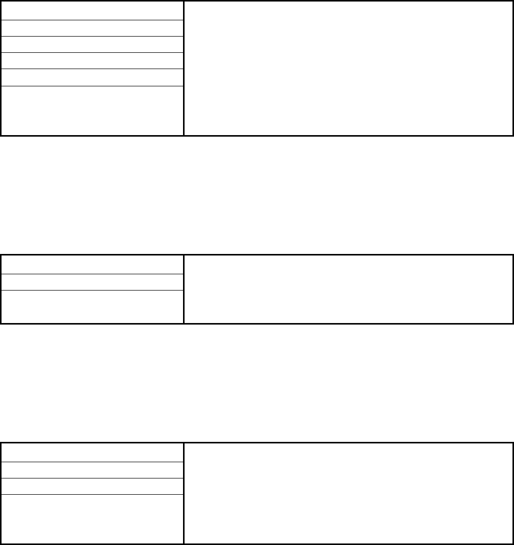
Sun Confidential: Internal Only
Account Information
> [electronic form] <
Host System Configuration Information
> [electronic form] <
VTSS Configuration Information
> [electronic form] <
Account (Company) Name
Site Number
Street Address
City / State / Province / Region
Zip or Postal Code / Country
Other Account Details
Host Name
Host Address
Other Host Configuration Details
VTSS Name
License Key
Time Zone Setting
Other VTSS Configuration Details

Sun Confidential: Internal Only
Customer Personnel Contacts
> [electronic form] <
Account ______________________________________
Data Center Manager (name)
Phone Numbers (office / cell)
E-Mail Address(es)
Other Contact Information
Network Administrator (name)
Phone Numbers (office / cell)
E-Mail Address(es)
Other Contact Information
Site Engineer (name)
Phone Numbers (office / cell)
E-Mail Address(es)
Other Contact Information
Facilities Manager (name)
Phone Numbers (office / cell)
E-Mail Address(es)
Other Contact Information
Data Center Operator (name)
Phone Numbers (office / cell)
E-Mail Address(es)
Other Contact Information
Delivery Dock Manager (name)
Phone Numbers (office / cell)
E-Mail Address(es)
Other Contact Information
Other Contact (name / job role)
Phone Numbers (office / cell)
E-Mail Address(es)
Other Contact Information
Other Contact (name / job role)
Phone Numbers (office / cell)
E-Mail Address(es)
Other Contact Information
Other Contact (name / job role)
Phone Numbers (office / cell)
E-Mail Address(es)
Other Contact Information

Sun Confidential: Internal Only
Sun StorageTek / QSP Personnel Contacts
> [electronic form] <
Account ______________________________________
Account Representative (name)
Phone Numbers (office / cell)
E-Mail Address(es)
Other Contact Information
System Engineer (name)
Phone Numbers (office / cell)
E-Mail Address(es)
Other Contact Information
System Support Specialist (name)
Phone Numbers (office / cell)
E-Mail Address(es)
Other Contact Information
Technical Support Specialist (name)
Phone Numbers (office / cell)
E-Mail Address(es)
Other Contact Information
Professional Services Mgr. (name)
Phone Numbers (office / cell)
E-Mail Address(es)
Other Contact Information
Customer Service Manager (name)
Phone Numbers (office / cell)
E-Mail Address(es)
Other Contact Information
Customer Service Engineer (name)
Phone Numbers (office / cell)
E-Mail Address(es)
Other Contact Information
Other Contact (name / job role)
Phone Numbers (office / cell)
E-Mail Address(es)
Other Contact Information
Other Contact (name / job role)
Phone Numbers office / cell)
E-Mail Address(es)
Other Contact Information

Sun Confidential: Internal Only
Planning Worksheet 1 of 5
> [electronic form] <
Account __________________________ Completed By ____________________ Date ___________
Site Readiness Planning Factors Information to Note / Comments
1A. Installation teams defined? 1A.
1B. Installation schedule created? 1B.
1C. HVAC requirements compliance verified? 1C.
1D. Power requirements compliance verified? 1D.
1E. Flooring requirements compliance verified? 1E.
1F. Future expansion considered? 1F.
1G. Floor plans completed? 1G.
1H. Cable routing established? 1H.
1I. Delivery team identified? 1I.
1J. Doorway clearances verified for transit of VTSS
cabinet(s) between dock and installation area? 1J.
1K. Delivery dock receiving time scheduled? 1K.
1L. Pallet jack / forklift availability verified? 1L.
1M. Incline compliance of ramp(s) verified? 1M.
1N. Elevator capacity verified? 1N.
1O. Pre-staging area readiness verified? 1O.
1P. Site and data center access arranged? 1P.
Additional Information to Note / Comments (Specify By Above Item Number):

Sun Confidential: Internal Only
Planning Worksheet 2 of 5
> [electronic form] <
Account __________________________ Completed By ____________________ Date ___________
Delivery and Handling Factors Information to Note / Comments
2A. Does the customer have a delivery dock? If NO, where
will the VTSS cabinet(s) be delivered? 2A.
2B. Are there street or alley limitations that will hinder
delivery of the VTSS cabinet(s)? 2B.
2C. Is the delivery dock available only during specific
hours? If YES, what are the hours of availability? 2C.
2D. Which specific persons (by name) will be used to move
and position the VTSS cabinet(s)? Note: A packaged
and fully-populated VTSS cabinet weighs up to 445 kg
(982 lbs.).
2D.
2E. Will a pallet jack or forklift with adjustable forks be avail-
able for moving the VTSS cabinet(s)? 2E.
2F. Is there a freight or public elevator available for moving
the VTSS cabinet(s) to the staging and installation ar-
eas, or must stairs be used? 2F.
2G. Are there ramps along the path between the delivery
dock and final installation area? If YES, have all ramp
inclines been verified to be within specification to pre-
vent tipping of the VTSS cabinet(s)? Note: Ramp
incline angles must NOT exceed 10 degrees.
2G.
2H. Are floors along the transit path to the installation area
rated to support the VTSS cabinet(s)? 2H.
Additional Information to Note / Comments (Specify By Above Item Number):

Sun Confidential: Internal Only
Planning Worksheet 3 of 5
> [electronic form] <
Account __________________________ Completed By ____________________ Date ___________
Safety and Fire Prevention Factors Information to Note / Comments
3A. Have all safety and fire-prevention codes and regula-
tions been reviewed for this VTSS installation? 3A.
Hardware / Software Procurement Factors Information to Note / Comments
3B. Has the VTSS configuration, including all features and
optional upgrades, been defined? 3B.
3C. Has the VTSS configuration, including all features and
optional upgrades, been ordered? 3C.
3D. Have needed lengths for power / ESCON channel / FI-
CON channel / modem cables, etc. been determined? 3D.
3E. Have needed lengths for power / ESCON channel / FI-
CON channel / modem cables, etc. been ordered? 3E.
3F. Have all required accessories and special tools been
ordered? 3F.
Environmental Factors Information to Note / Comments
3G. Does the installation area for the VTSS cabinet(s) com-
ply with all environmental requirements? 3G.
3H. Does the installation area for the VTSS cabinet(s) pro-
vide required levels of ventilation and / or cooling (i.e.,
adequate clearances for air circulation, adequate air-
flow for heat dissipation, etc.)?
3H.
3I. Does the installation area for the VTSS cabinet(s) con-
tain features and materials that provide protection
against electrostatic discharge (ESD)? 3I.
3J. Does the installation area for the VTSS cabinet(s) pro-
vide a stable environment free of extreme temperature
and humidity fluctuations? 3J.
Additional Information to Note / Comments (Specify By Above Item Number):

Sun Confidential: Internal Only
Planning Worksheet 4 of 5
> [electronic form] <
Account __________________________ Completed By ____________________ Date ___________
Physical Placement Factors Information to Note / Comments
4A. Does the installation area provide sufficient floor space
for all the hardware that comprises this VSM solution?4A.
4B. Does the installation area provide adequate lighting and
clearances for safety, operation, and maintenance of all
the hardware that comprises this VSM solution? 4B.
4C. Does the installation area have raised flooring? If YES,
are floor tile cut-outs needed? 4C.
4D. Does the installation area meet floor and floor-loading
requirements for all the hardware that comprises this
VSM solution? 4D.
AC Power Factors Information to Note / Comments
4E. Does the installation area meet all power requirements
for the hardware that comprises this VSM solution? 4E.
4F. Does the installation area have multiple separate cir-
cuits to supply the VTSS cabinet(s)? If YES, will the
customer provide multiple circuits for redundancy? 4F.
4G. What type and quantity of power cords, if any, will the
customer supply for the VTSS cabinet(s)? 4G.
4H. What type and quantity of power cords, if any, will
Sun Microsystems supply for the VTSS cabinet(s)? 4H.
4I. Are source power circuits for the VTSS cabinet(s) isolat-
ed to protect against fluctuations from lightning, outag-
es, etc.? 4I.
4J. Can source power circuits support the amperage (cur-
rent) required for the VTSS cabinet(s)? 4J.
4K. Is new electrical wiring needed to accommodate all the
hardware that comprises this VSM solution? If YES, will
this require inspection or approval to meet local codes? 4K.
Additional Information to Note / Comments (Specify By Above Item Number):

Sun Confidential: Internal Only
Planning Worksheet 5 of 5
> [electronic form] <
Account __________________________ Completed By ____________________ Date ___________
AC Power Factors Information to Note / Comments
5A. Does the installation site have capability for grounding
the VTSS cabinet(s)? 5A.
5B. Is the installation site close enough to source power
connectors / outlets to accommodate the power cord
lengths ordered for the VTSS cabinet(s)? 5B.
5C. Are power cable routing paths readily accessible to fa-
cilitate cable connection / disconnection and servicing? 5C.
Host System and Application Software Factors Information To Note / Comments
5D. What host operating system software will be used with
this VSM solution configuration? Requirements:
(1) MVS 5.2.2 or higher. (2) All versions of OS390.
5D.
(1) _____________________________________
(2) _____________________________________
5E. What application software release levels (SRLs) will be
installed for use with this VSM solution configuration?
Requirements: For back-end FICON (1) VTCS.
(2) NCS 6.1 or higher (includes HSC 6.1).
5E.
(1) _____________________________________
(2) _____________________________________
5F. What patches, if any, are needed for host and applica-
tion software to run properly with this VSM solution
configuration? Key: (1) = VTCS. (2) = NCS. (3) = MVS.
(4) = OS390.
5F.
(1) _____________________________________
(2) _____________________________________
(3) _____________________________________
(4) _____________________________________
Remote Support Factors Information To Note / Comments
5G. What components will the customer provide to enable
remote event notification functionality for this VSM solu-
tion? 5G.
5H. What components will Sun Microsystems provide to en-
able remote event notification functionality for this VSM
solution? 5H.
5I. What cable types and lengths are needed to attach a
modem, SDP device, or other remote monitoring com-
ponents to the VTSS cabinet(s)? 5I.
Additional Information to Note / Comments (Specify By Above Item Number):

Sun Confidential: Internal Only
Software Information
> [electronic form] <
Account ______________________________________
Use this electronic form to record key information (product names, versions, release levels, serial numbers, etc.) for
all software1 used with this VSM solution configuration, as a quick reference when reporting problems, validating
service entitlements, etc.
1. Including: VSM application software (VTCS, NCS, HSC), library software (ACSLS, Library Station), and MVS host system software.

Sun Confidential: Internal Only
Hardware Information – Tape Devices
> [electronic form] <
Account ______________________________________
Use this electronic form to record key information (product names, model numbers, serial numbers, etc.) for all tape
device hardware1 used with this VSM solution configuration, as a quick reference when reporting problems, validat-
ing service entitlements, etc.
1. May include: T9840B-C, T9940B, and T10000 tape drives; Timberline 9490 and 9490-M44 cartridge subsystems; SL8500, Nearline 4410,
PowderHorn 9310, WolfCreek 9360, and Timberwolf 9740 tape libraries.
NOTE:
To ensure accurate notations, identify tape devices by product name and type (e.g., 9940B tape
drive, SL8500 tape library, etc.) and by the unique designation used for the device within the
VSM solution configuration (Tape Drive 1, Tape Library 1, etc.).
Sun Confidential: Internal Only
Hardware Information – Switches / Routers
> [electronic form] <
Account ______________________________________
Use this electronic form to record key information (product names, model numbers, serial numbers, etc.) for all ex-
ternal switches, routers, or other hardware used with this VSM solution configuration, as a quick reference when
reporting problems, validating service entitlements, etc.
Sun Confidential: Internal Only
Hardware Information – SDP and Modem Devices
> [electronic form] <
Account ______________________________________
Use this electronic form to record key information (product names, model numbers, serial numbers, etc.) for all Ser-
vice Delivery Platform (SDP) and remote service modem hardware used with this VSM solution configuration, as a
quick reference when reporting problems, validating service entitlements, etc.
Sun Confidential: Internal Only
Notes / Additional Information
> [electronic form] <
Account ______________________________________
Sun Confidential: Internal Only
Notes / Additional Information
> [electronic form] <
Account ______________________________________
Sun Confidential: Internal Only
Notes / Additional Information
> [electronic form] <
Account ______________________________________
Sun Confidential: Internal Only
Notes / Additional Information
> [electronic form] <
Account ______________________________________
Sun Confidential: Internal Only
Notes / Additional Information
> [electronic form] <
Account ______________________________________

SUN™ THE NETWORK IS THE COMPUTER ©2006 Sun Microsystems, Inc. All rights reserved. Sun, Sun Microsystems, and the Sun logo are trademarks or registered trademarks of Sun Microsystems, Inc. in the
United States and other countries.
Sun Microsystems, Inc. 4150 Network Circle, Santa Clara, CA 95054 USA Phone 1-650-960-1300 or 1-800-555-9SUN Web sun.com
ARGENTINA: 5411-4317-5636 • AUSTRALIA: 1-800-550-786 • AUSTRIA: 43-1-601-26-0 • BALKANS: 301-6188-111 • BELGIUM: 32 2-704 89 83 • BRAZIL: 55-11-51872100 • BRUNEI: 65-216-8333 • CANADA: 1-800-422-8020 (GENERAL); 416-964-2001 (LEARNING MANAGEMENT SYSTEM SALES,TORONTO) • CHILE: 562-372-4500 • COLOMBIA: 571-629-2323
CZECH REPUBLIC: 420 2 33009311 • DENMARK: 45 4556 5040 • EGYPT: 00 202 570 9442 • FINLAND: 358-9-525-561 • FRANCE: 33-1-41-33-17-17 • GERMANY: 49-89-460-08-2788 • GREECE: 30-01-6188101 • HONG KONG: 852-2877-7077 • HUNGARY: 361-202-4415 • INDIA: 91-80-229-8989 • INDONESIA: 65-216-8333 • IRELAND: 353-1-668-4377
ISRAEL: 972-9-9710500 • ITALY: 39-02-9259511 • JAPAN: 81-3-5779-1820 • KOREA: 82-2-3453-6602 • MALAYSIA: 603-2116-1887 • MIDDLE EAST: 00 9714 3366333 • MEXICO: 525-261-0344 • NETHERLANDS: 31-33-4515200 • NEW ZEALAND: 0800-786-338 • NORTH WEST AFRICA: 00 9714 3366333 • NORWAY: FROM NORWAY: 47-22023950, TONORWAY:
47-23369650 • PAKISTAN: 00-9714-3366333 • PEOPLE'SREPUBLIC OF CHINA: 8610-6803-5588 • PHILIPPINES: 632-885-7867 • POLAND: 48-22-8747848 • PORTUGAL: 351-21-413-4000 • RUSSIA: 7-095-935-8411 • SAUDI ARABIA: 00 9714 3366333 • SINGAPORE: 65-216-8300 • SOUTH AFRICA: 27-11-256-6300 • SPAIN: 34-902-210-412 • SRI LANKA:
65-2168333 • SWEDEN: 46-8-631 22 00 • SWITZERLAND: 41-1-908-90-50 (GERMAN) 41-22-999-0444 (FRENCH) • TAIWAN: 886-2-25185735 • THAILAND: 662-344-6855 • TURKEY: 90 212 335 22 00 • UNITED KINGDOM: 44-1276-416-520 • UNITED STATES: 1-800-422-8020 • VENEZUELA: 582-905-3800 • VIETNAM: 65-216-8333 • WORLDWIDE
HEADQUARTERS:1-650-960-1300
