SunPower 523917 SunPower STAC (523917) User Manual
SunPower Corporation SunPower STAC (523917)
SunPower >
User Manual
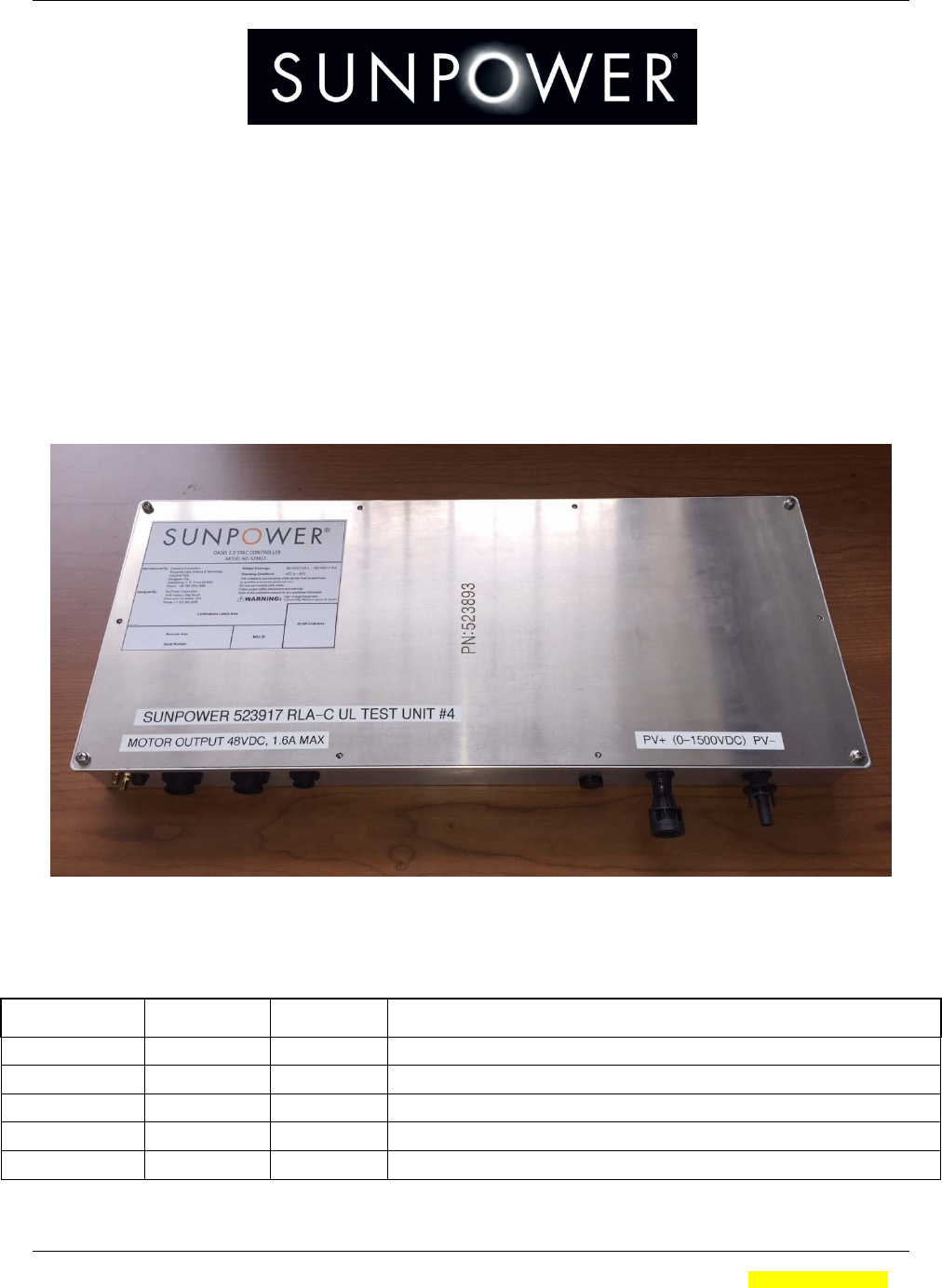
SUNPOWER CORPORATION Document #: 525731 Rev.01
OASIS 3 RLA PSc CONTROLLER -- Product Manual Page: 1 of 20
SunPower Corporation Proprietary Information Electronically Controlled. Latest revision is in the Document Management System.
A printed copy is uncontrolled and may be outdated unless it bears a red ink “controlled copy” stamp. Form # 000-00000 Rev 01
SunPower Corporation, 1414 Harbour Way South, Richmond, CA 94804
OASIS 3 RLA CONTROLLER
OWNER AND SAFETY MANUAL
(RLA PSc, 523917)
Product Manual
(Manual Part Number 525731, Arena)
Initiating Product Development Engineer: Kevin Fischer
Revision History
Date Revision Author Change
2017/09/11 01 KCF Initial

SUNPOWER CORPORATION Document #: 525731 Rev.01
OASIS 3 RLA PSc CONTROLLER -- Product Manual Page: 2 of 20
SunPower Corporation Proprietary Information Electronically Controlled. Latest revision is in the Document Management System.
A printed copy is uncontrolled and may be outdated unless it bears a red ink “controlled copy” stamp. Form # 000-00000 Rev 01
Table of Contents
FCC Statement Page ................................................................................................................. 4
UL Statement Page .................................................................................................................... 5
1.WARNINGS AND INSTRUCTIONS: ................................................................................ 6
3.PRODUCT SPECIFICATIONS .......................................................................................... 7
3.1.Electrical Specifications ............................................................................................ 7
3.2.Environmental specifications .................................................................................. 7
4.Manual Additions for Compliance with IEC62109 ..................................................... 7
4.1.Maintenance and Safety Instructions: ................................................................... 7
4.2.Environmental Requirements and Conditions: ................................................... 8
5.QUICK SET-UP GUIDE ...................................................................................................... 8
6.SUMMARY AND SCOPE ................................................................................................. 14
6.1.Technical Overview................................................................................................... 14
6.2.Key Features ............................................................................................................... 14
6.3.Product Range of Application ................................................................................ 15
7.PRODUCT CAPABILITIES .............................................................................................. 15
7.1.Power Entry and System Connectors .................................................................. 15
7.2.Controller System Theory of Operation .............................................................. 16
7.3.Controller System Troubleshooting Techniques ............................................. 16
7.4.Commissioning .......................................................................................................... 17
7.5.RLA PSc Status Indicator ........................................................................................ 17
8.IMAGES AND DRAWINGS .............................................................................................. 18
8.1.Block Diagram – RLA – PSc Controller ............................................................... 18
8.2.Block Diagram – RLA Controller Board .............................................................. 19
8.3.Block Diagram – RLA PSc Power Supply ........................................................... 20

SUNPOWER CORPORATION Document #: 525731 Rev.01
OASIS 3 RLA PSc CONTROLLER -- Product Manual Page: 3 of 20
SunPower Corporation Proprietary Information Electronically Controlled. Latest revision is in the Document Management System.
A printed copy is uncontrolled and may be outdated unless it bears a red ink “controlled copy” stamp. Form # 000-00000 Rev 01
CE Statement Page Update with specs from BACL testing)
DECLARATION OF CONFORMITY
Product Name: SunPower RLA Controller Brand Name: SUNPOWER
Model: RLA PSc
To which this declaration relates, is in conformity with the following standards and/or
other normative documents:
1. Health (Article 3.1(a) of the R&TTE Directive) applied Standard(s):
EN 62311: 2008, EN 50385: 2002
2. Safety (Article 3.1(a) of the R&TTE Directive) Applied Standard(s):
EN 60950-1: 2006 + A11: 2009 + A1: 2010 + A12: 2011 + A2: 2013
3. Electromagnetic compatibility (Article 3.1 (b) of the RED Directive) Applied
Standard(s):
EN 301 489-1 V1.9.2, EN 301 489-17 V2.2.1, EN 301 489-24 V1.5.1
EN 50561-1: 2013 / AC: 2015, EN 50412-2-1: 2005 / AC: 2009, EN 55022: 2010 /
AC: 2011 Class B, EN 61000-3-2: 2014, EN 61000-3-3: 2013, EN 55024: 2010
4. Radio frequency spectrum usage (Article 3.2 of the R&TTE Directive) Applied
Standard(s):
EN 300 328 V1.9.1
EN 301 908-1 V7.1.1
We hereby declare that the above named product is inconformity to all the essential
requirements of directive 1999/5/EC.
The conformity assessment procedure referred to in Article 10 and detailed in Annex [III]
or [IV] of Directive 1999/5/EC has been followed with the involvement of the following
Notified Body:
Timco Engineering, Inc.
Identification mark: ???? (Notified Body)
????
The technical documentation relevant to the above equipment will be held at:
SunPower Corporation
1414 Harbour Way South, Richmond, CA 94804, USA
Authorized Person: Kevin Fischer
SUNPOWER CORPORATION Document #: 525731 Rev.01
OASIS 3 RLA PSc CONTROLLER -- Product Manual Page: 4 of 20
SunPower Corporation Proprietary Information Electronically Controlled. Latest revision is in the Document Management System.
A printed copy is uncontrolled and may be outdated unless it bears a red ink “controlled copy” stamp. Form # 000-00000 Rev 01
FCC Statement Page
DECLARATION OF CONFORMITY
Product Name: SunPower RLA Controller
Brand Name: SUNPOWER
Model: RLA part number 523917
FCC ID: YAW523917
This device complies with Part 15 of the FCC Rules
Operation is subject to the following conditions:
1. The devices may not cause harmful interference, and
2.
The devices must accept any interference received, including interference that may cause
undesired operation
Note: This equipment has been tested and found to comply with the limits for a Class A digital device,
pursuant to part 15 of the FCC Rules. These limits are designed to provide reasonable protection against
harmful interference when the equipment is operated in a commercial environment. This equipment
generates, uses, and can radiate radio frequency energy and, if not installed and used in accordance with
the instruction manual, may cause harmful interference to radio communications. Operation of this
equipment in a residential area is likely to cause harmful interference in which case the user will be
required to correct the interference at their own expense.
Changes or modifications not expressly approved by the manufacturer (Party responsible for compliance)
could void the user's authority to operate the equipment under FCC rules.

SUNPOWER CORPORATION Document #: 525731 Rev.01
OASIS 3 RLA PSc CONTROLLER -- Product Manual Page: 5 of 20
SunPower Corporation Proprietary Information Electronically Controlled. Latest revision is in the Document Management System.
A printed copy is uncontrolled and may be outdated unless it bears a red ink “controlled copy” stamp. Form # 000-00000 Rev 01
UL Statement Page

SUNPOWER CORPORATION Document #: 525731 Rev.01
OASIS 3 RLA PSc CONTROLLER -- Product Manual Page: 6 of 20
SunPower Corporation Proprietary Information Electronically Controlled. Latest revision is in the Document Management System.
A printed copy is uncontrolled and may be outdated unless it bears a red ink “controlled copy” stamp. Form # 000-00000 Rev 01
1. WARNINGS AND INSTRUCTIONS:
SAVE THESE INSTRUCTIONS- THIS MANUAL CONTAINS IMPORTANT
INSTRUCTIONS FOR THE RLA PSc CONTROLLER THAT SHALL BE FOLLOWED
DURING INSTALLATION, MAINTENANCE AND COMMISSIONING OF THE BOXES.
YOU MUST FOLLOW THESE INSTRUCTIONS DURING INSTALLATION AND/OR
MAINTENANCE OF THESE COMBINER BOXES!
IF EQUIPMENT IS USED IS A MANNER NOT SPECIFIED, THE PROTECTION
PROVIDED BY THE EQUIPMENT MAY BE IMPAIRED.
WARNING! THE INSTALLATION OR MAINTENANCE OF RLA CONTROLLER
UNITS INVOLVES RISK OF CONTACT WITH POTENTIALLY LETHAL VOLTAGES
AND CURRENTS.
NO ATTEMPT TO SERVICE THE SYSTEM SHOULD BE MADE. THRE ARE NO
SERVICABLE PARTS INSIDE. THE UNIT IS DESIGNED TO BE REPLACED ON-
SITE, AND REPAIRED AT THE FACTORY.
WARNING! WHEN THE PHOTOVOLTAIC ARRAY IS EXPOSED TO LIGHT, IT
SUPPLIES A DC VOLTAGE TO THE RLA CONTROLLER UNIT.
Installers should be advised:
ALWAYS wear the appropriate PPEs when working on this system!
ALWAYS use the proper Lock Out – Tag Out procedures!
NEVER install and connect an RLA Controller that is wet, or where your safety is
compromised in any way!
These installation instructions are for use by qualified personnel only.
The equipment contains lethal DC voltages.
The fuses and holders are not for current interrupt. Do not open the DC Input
Connectors unless the system is open-circuited in the main array.
The inverters contain energy storage devices that require 15 minutes in order to
safely discharge their lethal voltages.
Handle broken or damaged PV modules or wiring with extreme caution.
Maximum Ambient temperature for guaranteed operation is 55°C.
COMPLIANCE
This Tracker System and RLA Controller has been designed and is built in compliance
with the following standards:
UL1741 - Standard for Inverters, Converters, Controllers and Interconnect Equipment
for use with Distributed Energy Resources
ISO 62109-1 - Safety of Power converters for use in photovoltaic power systems
SUNPOWER CORPORATION Document #: 525731 Rev.01
OASIS 3 RLA PSc CONTROLLER -- Product Manual Page: 7 of 20
SunPower Corporation Proprietary Information Electronically Controlled. Latest revision is in the Document Management System.
A printed copy is uncontrolled and may be outdated unless it bears a red ink “controlled copy” stamp. Form # 000-00000 Rev 01
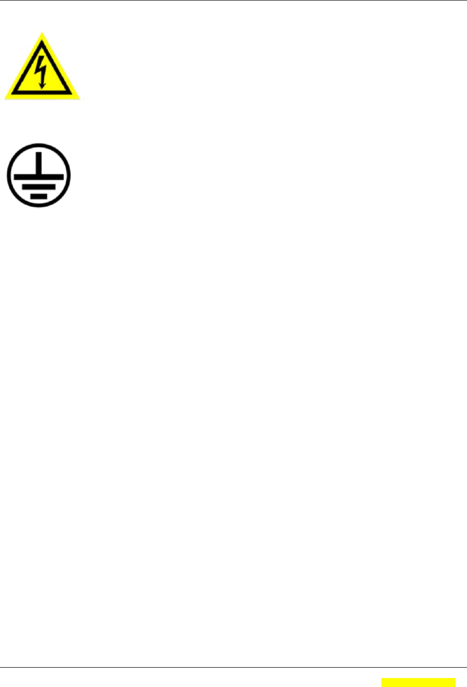
EXPLANATION OF SYMBOLS:
ELECTRICAL SHOCK HAZARD- These labels are used to mark components where
potentially lethal voltages exist.
GROUND- This identifies the equipment grounding points.
3. PRODUCT SPECIFICATIONS
3.1. Electrical Specifications
Nominal DC Input Voltage: 360-1500VDC
Maximum DC Input Current: < 0.50A
Nominal DC Output Voltage: 48VDC (two channels)
Maximum DC Output Current: 1.60A per channel
Nominal Operating Power: < 25W
Maximum Operating Power: < 215W
3.2. Environmental specifications
Minimum Operating Temperature: -40° C
Maximum Operating Temperature: +55° C
Maximum Storage Temperature: +70° C
Relative Humidity: 5% to 95%, non-condensing
Enclosure Rating: UL50E and Type 4x
4. Manual Additions for Compliance with IEC62109
4.1. Maintenance and Safety Instructions:
No preventive maintenance is required on this equipment. It is designed to be
maintenance free.
There are no operator accessible areas on this device. This unit is not intended
for field maintenance, and is not to be opened in the field. Do not attempt to
open this device in the field.
This device has no serviceable part inside. Do not attempt to open or service in
the field.

SUNPOWER CORPORATION Document #: 525731 Rev.01
OASIS 3 RLA PSc CONTROLLER -- Product Manual Page: 8 of 20
SunPower Corporation Proprietary Information Electronically Controlled. Latest revision is in the Document Management System.
A printed copy is uncontrolled and may be outdated unless it bears a red ink “controlled copy” stamp. Form # 000-00000 Rev 01
Cleaning instructions: The RLA unit, including the label, may be cleaned with
isopropyl alcohol if required.
PV disconnection tool is required to remove the PV input wires.
A tool is required to remove the motor cable protection clamps, if installed.
There are NO adjustments or controls accessible physically on the unit. There
are adjustments that can be accomplished remotely.
There are no accessories that can be attached to the RLA controller. The only
part that can be removed other than the RLA unit from the tracker, is the current
sensor attached to the side of the unit. There is no shock hazard associated with
removing this part.
There are no hot surfaces on this enclosure that exceed 70C in normal operation
at the rated ambient temperature of 55C.
If the equipment is used in a manner not specified by SunPower, the protection
provided by the equipment may be impaired.
4.2. Environmental Requirements and Conditions:
This product is suitable for wet locations.
The Pollution Degree Rating of this product is PD3.
This product ingress protection rating is IP67.
The enclosure and connector on this product have appropriate UV exposure
ratings for outside operation per UL50e testing.
Touch current for this device is under 500uA when ungrounded.
Ambient temperature and relative humidity ratings are described in section 3.2
above.
5. QUICK SET-UP GUIDE
Below is a quick overview of the installation process for the RLA controller.
First, please familiarize yourself with the features and connectors on the RLA
controller.
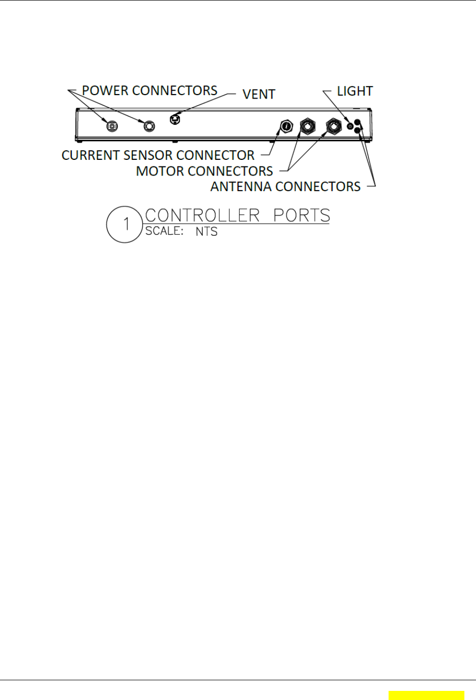
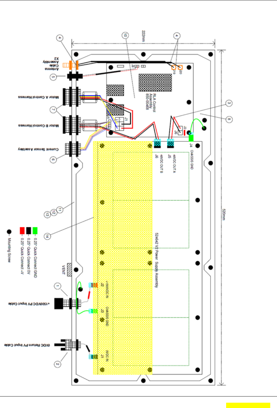
The controller has the following connectors and ports:
1) Two DC power input connectors. These are standard PV style connectors
rated for 1500VDC operation.
2) A Current Sense connectors which is used to connect a sensor that monitors
the current flowing through the monitored PV lines.
3) Two motor control connectors that provide power and communications to
the two motors in the tracker. Please note that the RLA controller
automatically senses whether the connector is connected to Motor #1 or
Motor #2.
4) Two RP-SMA connectors that the external antennas are connected to.
5) An indicator light that signals that the unit is “on” and blinks when there is
radio activity.
SUNPOWER CORPORATION Document #: 525731 Rev.01
OASIS 3 RLA PSc CONTROLLER -- Product Manual Page: 9 of 20
SunPower Corporation Proprietary Information Electronically Controlled. Latest revision is in the Document Management System.
A printed copy is uncontrolled and may be outdated unless it bears a red ink “controlled copy” stamp. Form # 000-00000 Rev 01
6) A vent that is used to equalize pressure and vent potential moisture out of
the controller.
Figure 1. Image showing the connectors and ports on the RLA controller
SUNPOWER CORPORATION Document #: 525731 Rev.01
OASIS 3 RLA PSc CONTROLLER -- Product Manual Page: 10 of 20
SunPower Corporation Proprietary Information Electronically Controlled. Latest revision is in the Document Management System.
A printed copy is uncontrolled and may be outdated unless it bears a red ink “controlled copy” stamp. Form # 000-00000 Rev 01
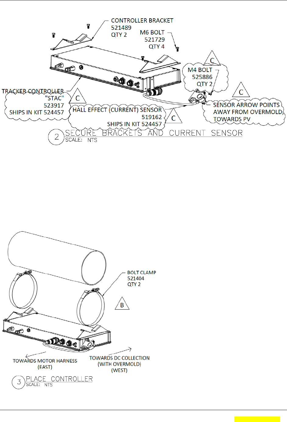
A. INSTALL CONTROLLER WITH SENSOR
Figure 2. Image showing the RLA controller and how the mounting brackets and
current sensor are attached.
a. ATTACH CONTROLLER BRACKETS TO CONTROLLER CASING USING M6
BOLTS. TORQUE TO 80 IN-LB (9 N*M)
b. ATTACH SENSOR TO CONTROLLER CASING USING M4 BOLTS. SNUG THE
BOLTS. PLUG IN THE SENSOR.
Figure 3. Image showing the RLA controller and its relationship to the torque tube
and bolt clamps.
SUNPOWER CORPORATION Document #: 525731 Rev.01
OASIS 3 RLA PSc CONTROLLER -- Product Manual Page: 11 of 20
SunPower Corporation Proprietary Information Electronically Controlled. Latest revision is in the Document Management System.
A printed copy is uncontrolled and may be outdated unless it bears a red ink “controlled copy” stamp. Form # 000-00000 Rev 01
a. LOCATE CONTROLLER BETWEEN STRUTS AS SHOWN IN LAYOUT AND
ATTACH USING BOLT CLAMPS.
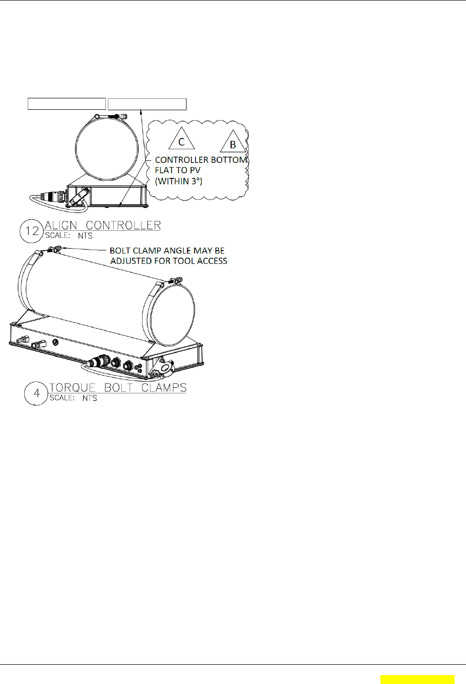
b. ALIGN CONTROLLER AND TORQUE BOLT CLAMPS TO 75 IN-LB (8.5N*M)
Figure 4. Image showing the RLA controller mounted to the torque tube.
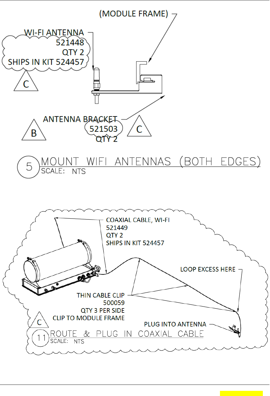
B. INSTALL ANTENNAS (Final antenna details pending)
a. CLIP CONTROLLER ANTENNAS TO OUTERMOST MODULE FRAMES AS
SHOWN.
b. ROUTE ANTENNA WIRES BACK TO THE CONTROLLER USING CLIPS AS
SHOWN.
c. REMOVE ANTENNA CONNECTOR PROTECTION CAPS AND PLUG IN
ANTENNAS TO CONTROLLER.
SUNPOWER CORPORATION Document #: 525731 Rev.01
OASIS 3 RLA PSc CONTROLLER -- Product Manual Page: 12 of 20
SunPower Corporation Proprietary Information Electronically Controlled. Latest revision is in the Document Management System.
A printed copy is uncontrolled and may be outdated unless it bears a red ink “controlled copy” stamp. Form # 000-00000 Rev 01
Figure 6. Image showing the antenna bracket mounted to the module frame.
Figure 7. Image showing the antenna cable and clips.
SUNPOWER CORPORATION Document #: 525731 Rev.01
OASIS 3 RLA PSc CONTROLLER -- Product Manual Page: 13 of 20
SunPower Corporation Proprietary Information Electronically Controlled. Latest revision is in the Document Management System.
A printed copy is uncontrolled and may be outdated unless it bears a red ink “controlled copy” stamp. Form # 000-00000 Rev 01
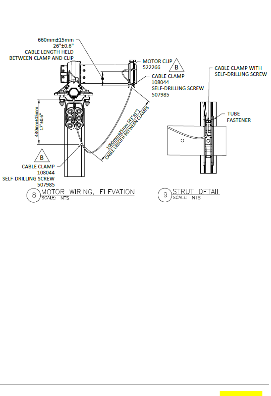
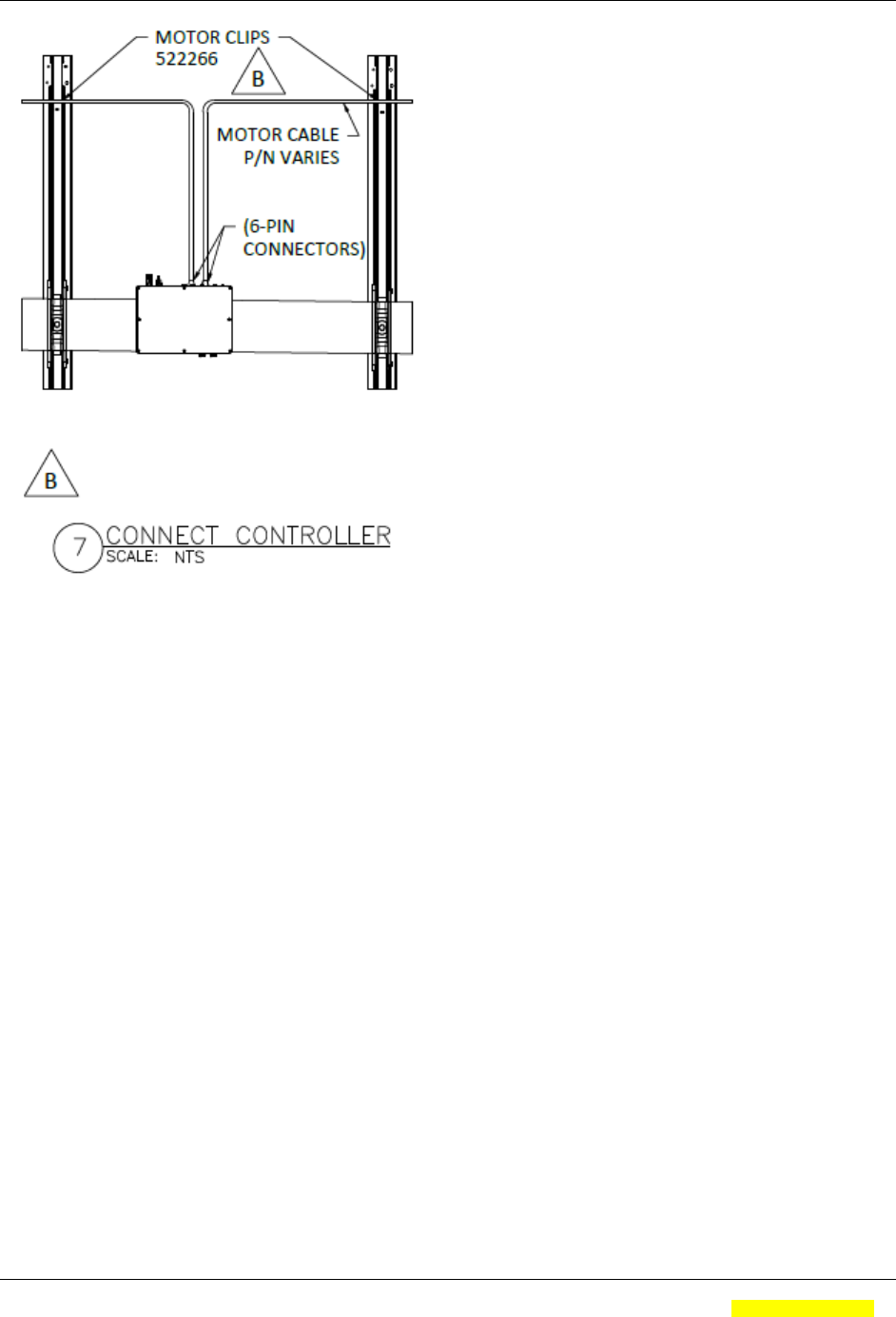
C. INSTALL MOTOR WIRING
Figure 8. Image showing the motor wiring from the torque tube to the motors.
a. INSTALL SHORT MOTOR CABLE CLOSER TO THE DC DISCONNECT,
PER MOTOR WIRING DETAIL.
b. UNROLL AND CONNECT THE WIRING HARNESS TO THE CONTROLLER
BAY, ROUTE THE MOTOR CABLE TO BOTH ADJACENT STRUTS WITH
NO EXCESS LENGTH, AS SHOWN.
c. CLIP MOTOR CABLE TO STRUTS BETWEEN CONTROLLER BAY AND
MOTOR #1 AS SHOWN, WITH EXCESS LENGTH DISTRIBUTED EVENLY
ALONG THE TRACKER.
d. UNROLL THE REMAINING WIRE AND INSTALL LONG MOTOR CABLE
FURTHER FROM THE DC DISCONNECT, PER MOTOR WIRING DETAIL.
e. CLIP MOTOR CABLE TO STRUTS BETWEEN CONTROLLER BAY AND
f. MOTOR #2 AS SHOWN, WITH EXCESS LENGTH DISTRIBUTED EVENLY
ALONG THE TRACKER.
SUNPOWER CORPORATION Document #: 525731 Rev.01
OASIS 3 RLA PSc CONTROLLER -- Product Manual Page: 14 of 20
SunPower Corporation Proprietary Information Electronically Controlled. Latest revision is in the Document Management System.
A printed copy is uncontrolled and may be outdated unless it bears a red ink “controlled copy” stamp. Form # 000-00000 Rev 01
Figure 9. Image showing the motor cables and their connection and routing to the
RLA controller.
D. CONNECT PV WIRING
a. INSTALL PV CABLES TO PROVIDE POWER TO THE CONTROLLER,
ONLY WHEN INSTRUCTED!
6. SUMMARY AND SCOPE
6.1. Technical Overview
The SunPower RLA Controller (RLA PSc) is an electrical enclosure and device that is
used as part of the OASIS 3 Row Level Tracker.
This unit accepts input power from the PV array, converts it to 48VDC to power an
internal controller and two external tracking motors.
6.2. Key Features
The RLA PSc has the following key features:
The RLA PSc accepts 360-1500VDC input so that it is self-powered from
the PV array.
The RLA PSc has an internal processor board that controls two external
stepper motors that are used to track the PV array.
The RLA PSc uses WiFi to communicate with the Station Hub which
provides detailed tracking information and control information.

SUNPOWER CORPORATION Document #: 525731 Rev.01
OASIS 3 RLA PSc CONTROLLER -- Product Manual Page: 15 of 20
SunPower Corporation Proprietary Information Electronically Controlled. Latest revision is in the Document Management System.
A printed copy is uncontrolled and may be outdated unless it bears a red ink “controlled copy” stamp. Form # 000-00000 Rev 01
The RLA PSc has an input port for collecting DC current flow data from
the array for precise output monitoring, and contains a 3 axis sensor that
determines tracker angle.
The RLA PSc is rated for operation from -20°C to +55°C ambient
temperature
The RLA PSc is UL listed, and rated as an FCC Class A computing device
The RLA PSc utilizes a self-heat-sinking aluminum enclosure that meets
UL50E.
6.3. Product Range of Application
It is intended that the RLA PSc will only be used for controlling OASIS 3 trackers. It is
not intended for residential applications or other uses.
7. PRODUCT CAPABILITIES
It is intended that the RLA PSc will provide real-time control data and error indication
back to the Station Hub.
7.1. Power Entry and System Connectors
0-1500VDC can enter the two standard PV connectors on the side of the control
unit.
While the input can range from 0-1500VDC, the unit will not turn on until the input
voltage exceeds 360VDC, at which, operation can commence.
The input voltage is converted to two separate 48VDC supply busses, which are
used to power the internal control board and power the two external stepper
motors for tracking.
Two external motor connectors are used to run Motor #1 (closest to the
controller) and Motor #2 (furthest from the controller), which are located on
opposite ends of the tracker.
Each motor connector can supply 48VDC @ 1.6 Amps for running the stepper
motor, and includes a CANBUS mode of communications to control and
interrogate the motors.
There is an input connector for an external Hall Effect sensor that is used to
measure the current running through the PV power lines.
The enclosure has two SMA style RF connectors for external WiFi antennas.
These are used for commissioning the controller, and communicating with the
station Hub.
The enclosure has one green LED with blinks to indicate internal activity.

SUNPOWER CORPORATION Document #: 525731 Rev.01
OASIS 3 RLA PSc CONTROLLER -- Product Manual Page: 16 of 20
SunPower Corporation Proprietary Information Electronically Controlled. Latest revision is in the Document Management System.
A printed copy is uncontrolled and may be outdated unless it bears a red ink “controlled copy” stamp. Form # 000-00000 Rev 01
7.2. Controller System Theory of Operation
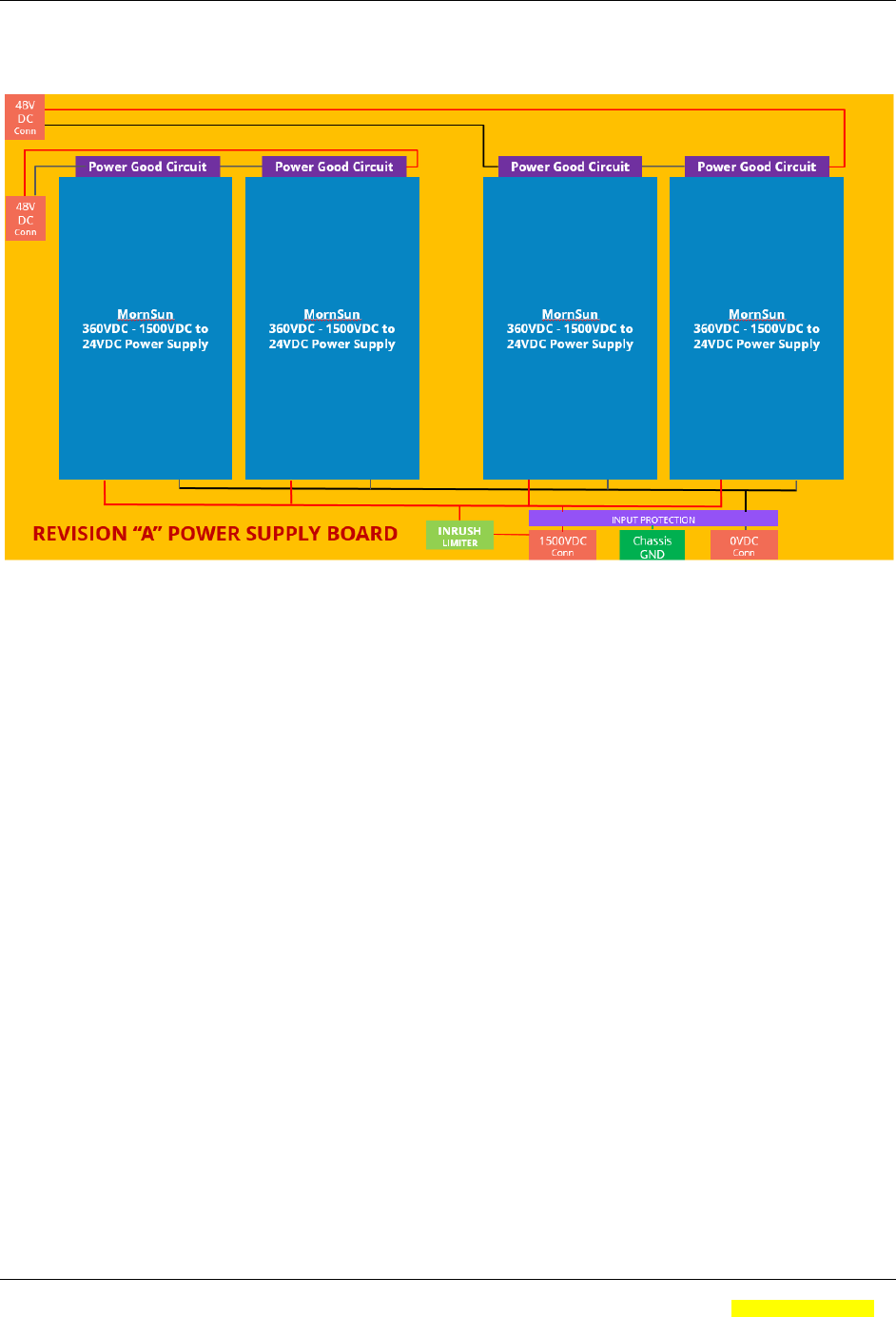
The RLA controller, with its integrated PV to 48VDC power supplies, forms the heart of
the Oasis 3 tracker system. It controls the tracking functionality on a row by row basis.
The functionality of the RLA controller and its operational capabilities are itemized
below:
1) The RLA takes in 0-1500VDC from the PV array, and converts this voltage to two
separate 48VDC power supplies to run the smart tracker motors. Power for the
smart motors is designed to start when the input reaches 360VDC.
2) One power supply is used to power the RLA control board, and one of the smart
tracking motors. The second power supply is used to power the second smart
motor.
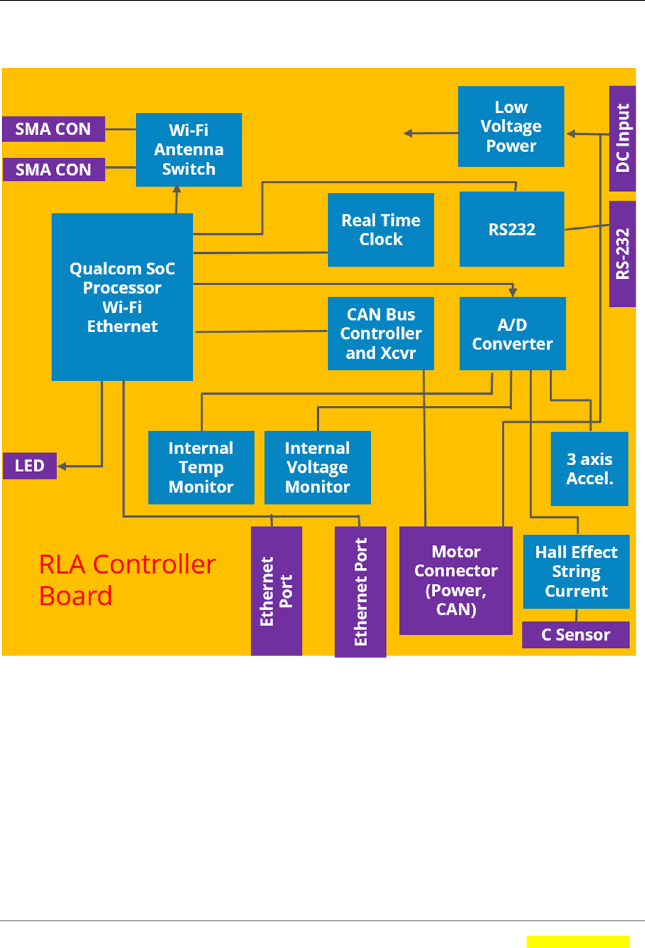
3) The RLA controller is a processor based control board is designed to accomplish
the following tasks:
a. Perform single axis sun position tracking, with site orientation correction.
b. Shall be capable of performing backtracking in a planar array configuration.
c. Provide a configurable night stow mode, a configurable rapid wind stow mode, a
configurable snow stow mode, a configurable cleaning position mode, and
provide a manual positioning mode.
d. Detect and recover from motor stall conditions – exceptions are an immovable
object or a sustained wind outside of design envelope.
e. Be capable of maintaining tracking accuracy in autonomous mode for a user
configurable amount of time without interaction with the Station Controller.
f. Provide string current measurement capability of 0.1% precision, ±0.2%
repeatability over a 24 hour period, and 1% accuracy.
g. Provide temperature measurement capability of 0.1° precision and ±0.5°
accuracy.
h. Allow for communication over Wi-Fi or Ethernet for commissioning,
communications with the Station Hub, or maintenance.
i. Provide a mechanism (CAN Bus) for communicating and powering (48VDC) with
the smart motors.
4) The RLA controller has a number of external connectors, including:
a. Two connectors for powering and communicating with two smart motors.
b. Two SMA antenna ports for connecting to the tracker mounted WiFi antennas for
communications.
c. A connector for an external current sensor so that string current can be
measured and reported.
d. And two high voltage DC input connectors (standard PV connectors) for
powering the RLA unit.
5) The RLA controller works in conjunction with the RLA Station Hub using WiFi
communications.
6) The RLA controller also controls the two Smart motors used to drive the tracker by
providing them with power (48VDC) and high level commands using CAN bus.
7.3. Controller System Troubleshooting Techniques
It is intended that RLA PSc can be commissioned and diagnosed in the field through a
few, simple troubleshooting techniques. The unit is sealed, and not intended to be
opened or repaired in the field! Below is the main troubleshooting flow:

SUNPOWER CORPORATION Document #: 525731 Rev.01
OASIS 3 RLA PSc CONTROLLER -- Product Manual Page: 17 of 20
SunPower Corporation Proprietary Information Electronically Controlled. Latest revision is in the Document Management System.
A printed copy is uncontrolled and may be outdated unless it bears a red ink “controlled copy” stamp. Form # 000-00000 Rev 01
1) Using a voltmeter, measure 48VDC at the output terminals (+ and -) of both
motor connectors.
2) If the proper voltage are present, proceed to section 5).
3) If there is no output voltage, check that the two PV input connectors have
360VDC to 1500VDC present.
a. If there is no input voltage, verify that the PV circuits are active and
properly connected.
b. Verify that the two input fuses are intact and can pass current.
4) If the input voltages are within limits, and both motor connectors are nominally
48VDC:
a. proceed to step 4.
b. If not, the RLA unit should be replaced.
5) Verify that the Green RLA indicator is blinking (after waiting at least 1 minute
from power-on).
a. If the indicator did not blink for ½ seconds when powered-on, and starts
regular blinking after about 1 minute from power-on, replace the RLA
controller.
6) When the green indicator LED is verified blinking, use the commissioning tablet
and application, and verify that you can detect the controller from the tablet,
(which identifies itself with its MAC id (printed on the label)).
a. If you cannot find the controller on the tablet, verify that the WiFi antennas
are properly connected to the unit and undamaged.
b. If the antennas are properly connected, and you still cannot detect the
RLA controller, replace the RLA unit.
7) When testing is complete, you should have:
a. 48VDC at the output terminals of the power supply,
b. A flashing green activity indicator on the RLA controller,
c. The controller should be WiFi connected (or visible) to the commissioning
tablet computer.
7.4. Commissioning
a. Please refer to RLA Commissioning Guide, Arena Part # 524???
7.5. RLA PSc Status Indicator
The RLA PSc has one LED indicator
a. The LED blinks Green for 0.5 seconds when power is first applied to the unit.
b. The LED will stay off for about a minute while the internal controller is booting.
c. The LED will blink when it detects external control communications with other
RLA controllers and the Station Hub.
SUNPOWER CORPORATION Document #: 525731 Rev.01
OASIS 3 RLA PSc CONTROLLER -- Product Manual Page: 18 of 20
SunPower Corporation Proprietary Information Electronically Controlled. Latest revision is in the Document Management System.
A printed copy is uncontrolled and may be outdated unless it bears a red ink “controlled copy” stamp. Form # 000-00000 Rev 01
8. IMAGES AND DRAWINGS
8.1. Block Diagram – RLA – PSc Controller
SUNPOWER CORPORATION Document #: 525731 Rev.01
OASIS 3 RLA PSc CONTROLLER -- Product Manual Page: 19 of 20
SunPower Corporation Proprietary Information Electronically Controlled. Latest revision is in the Document Management System.
A printed copy is uncontrolled and may be outdated unless it bears a red ink “controlled copy” stamp. Form # 000-00000 Rev 01
8.2. Block Diagram – RLA Controller Board
SUNPOWER CORPORATION Document #: 525731 Rev.01
OASIS 3 RLA PSc CONTROLLER -- Product Manual Page: 20 of 20
SunPower Corporation Proprietary Information Electronically Controlled. Latest revision is in the Document Management System.
A printed copy is uncontrolled and may be outdated unless it bears a red ink “controlled copy” stamp. Form # 000-00000 Rev 01
8.3. Block Diagram – RLA PSc Power Supply
< End of Document >