Sunray Medical Apparatus FHR Wireless Ultrasound Transducer User Manual
Sunray Medical Apparatus Co.,Ltd Wireless Ultrasound Transducer
User Manual

F
F
Fe
e
et
t
ta
a
al
l
l
M
M
Mo
o
on
n
ni
i
it
t
to
o
or
r
r
M
M
Mo
o
od
d
de
e
el
l
l:
:
:
S
S
SR
R
RF
F
F6
6
61
1
18
8
8B
B
B6
6
6
U
U
Us
s
se
e
er
r
r’
’
’s
s
s
M
M
Ma
a
an
n
nu
u
ua
a
al
l
l
Manufacturer’s Statement
This manual should be used as a reference for operating this instrument only. This company will not
undertake any consequence and responsibility produced by using this manual for other purposes.
This manual contains proprietary information, which is copyright protected and all rights reserved. Any
part of this manual shall not be copied, duplicated or translated into other languages without prior written
approval by our company.
The information contained in this manual is subject to change without notice.
As a result of technical update or user’s special requirement, some parts or components may be somewhat
different from the standard configuration specified in this manual as long as the performance indexes of the
instrument are not affected. Please keep this in mind.
Caution: Federal law restricts this device sale by or on the order of a physician
Manufacturer
Sunray Medical Apparatus Co., Ltd.
Head Office: 4/F No.242 Tianhe Dong Road, Guangzhou,
People’s Republic of China
Postal code: 510620
Tel: 86-20-8757-0362/8750-2927
Fax: 86-20-8758-3004/8751-4127
Website: www.sunra
y
-cn.com
EU REPRESENTATIVE:
Shanghai International Holding Corp. GmbH(Europe)
ADDRESS: Eiffestrasse 80, 20537 Hamburg Germany
Tel: 0049-40-2513175 Fax: 0049-40-255726
E-mail: shholding@hotmail.com
Copyright © Guangzhou Sunray Medical Apparatus Co., Ltd
Version number: US1.0
Date: Nov. 2015
0123

S
S
SR
R
RF
F
F6
6
61
1
18
8
8B
B
B6
6
6
U
U
Us
s
se
e
er
r
r’
’
’s
s
s
M
M
Ma
a
an
n
nu
u
ua
a
al
l
l
Commitment
Our company guarantees that this instrument will not have any quality problem in material and technology
within the guarantee period promised by our company. If the product purchased by the user has such a kind
of quality problem, please notice our company. Our company will provide warranty for the user free of
charge, and will repair or replace the product that is proved to be defective according to actual
circumstances. Please see the “Stipulations for Warranty” specified on the “Warranty Card” for details.
The warranty is void in cases of:
a) damage caused by mishandling during shipping;
b) subsequent damage caused by improper use or maintenance;
c) damage caused by alteration or repair by anyone not authorized by Sunray;
d) damage caused by accidents;
e) replacement or removal of serial number label and manufacture label;
If a product covered by this warranty is determined to be defective because of defective materials,
components, or workmanship, and the warranty claim is made within the warranty period, Sunray will, at
its discretion, repair or replace the defective part(s) free of charge. Sunray will not provide a substitute
product for use when the defective product is being repaired.
The designed service life of this product is 5 years. This company will provide repair service for the user
within the term of the service life.
Note: Consumables such as recorder paper, ultrasonic coupling agent, and recorder cartridge etc. are
out of the scope of warranty.
Caution: Federal law restricts this device sale by or on the order of a physician
Terms Used in this Manual
This guide is designed to give key concepts on safety precautions.
WARNING
A WARNING label advises against certain actions or situations that could result in personal injury or death.
CAUTION
A CAUTION label advises against actions or situations that could damage equipment, produce inaccurate
data, or invalidate a procedure.
NOTE
A NOTE provides useful information regarding a function or a procedure.

S
S
SR
R
RF
F
F6
6
61
1
18
8
8B
B
B6
6
6
U
U
Us
s
se
e
er
r
r’
’
’s
s
s
M
M
Ma
a
an
n
nu
u
ua
a
al
l
l
Table of Contents
Manufacturer’s Statement ........................................................................................................................... 2
Chapter 1Safety guidance .......................................................................................................................... 1
1.1Indications for Use ..................................................................................................................... 1
1.2Contraindication ......................................................................................................................... 1
1.3Patient Populations ..................................................................................................................... 1
1.4Warning ...................................................................................................................................... 1
1.5Safety Notes ............................................................................................................................... 3
1.6Definition and Symbols .............................................................................................................. 4
Chapter 2Overview of the Instrument ........................................................................................................ 6
2.1Expected Functions and Purposes .............................................................................................. 6
2.2Configurations ............................................................................................................................ 6
2.3Overview .................................................................................................................................... 6
2.4Accessories ................................................................................................................................. 9
2.5Screen ....................................................................................................................................... 10
2.6Ordering Information ............................................................................................................... 12
Chapter 3Installation Guide ..................................................................................................................... 14
3.1Unpacking and checking .......................................................................................................... 14
3.2Installing Battery ...................................................................................................................... 14
3.3Installation ................................................................................................................................ 15
3.4Connecting Power Cable .......................................................................................................... 15
Chapter 4Alarm ........................................................................................................................................ 16
4.1Alarm classification .................................................................................................................. 16
4.2Audible Alarm .......................................................................................................................... 16
4.3Visual Alarm ............................................................................................................................. 17
4.4Reviewing Alarms .................................................................................................................... 17
4.5Alarm Treatment Measures ...................................................................................................... 18
4.6Testing Alarms .......................................................................................................................... 19
4.7Physiological Alarm Defaults ................................................................................................... 19
4.8Alarm information .................................................................................................................... 20
Chapter 5Printing ..................................................................................................................................... 21
5.1Function Description ................................................................................................................ 21
5.2Loading Recorder paper ........................................................................................................... 21
5.3Choosing Paper Speed .............................................................................................................. 22
5.4Print Self-Check ....................................................................................................................... 22
5.5Select the printing range ........................................................................................................... 22
5.6Print the traces .......................................................................................................................... 23
5.7Understanding Recorder Paper Printout ................................................................................... 24
5.8Tearing Off the Paper ............................................................................................................... 25
Chapter 6Settings ..................................................................................................................................... 26

S
S
SR
R
RF
F
F6
6
61
1
18
8
8B
B
B6
6
6
U
U
Us
s
se
e
er
r
r’
’
’s
s
s
M
M
Ma
a
an
n
nu
u
ua
a
al
l
l
Chapter 7Pre-monitoring Preparation ...................................................................................................... 32
7.1Switching On ............................................................................................................................ 32
7.2Adjusting Screen Angle ............................................................................................................ 32
7.3Setting Date and Time .............................................................................................................. 32
7.4Connecting Transducers ........................................................................................................... 32
7.5Placing Transducers in the Holder ............................................................................................ 33
Chapter 8Fetal Monitoring ....................................................................................................................... 35
8.1Confirming Fetal Life ............................................................................................................... 35
8.2Monitoring FHR with Ultrasound ............................................................................................ 35
8.3Monitoring Twin FHRs ............................................................................................................ 37
8.4Monitoring Triple FHRs ........................................................................................................... 37
8.5Monitoring Uterine Activity Externally ................................................................................... 38
8.6Monitoring Fetal Movement .................................................................................................... 39
8.7Start Monitoring ....................................................................................................................... 40
8.8Inputting Maternal Information ................................................................................................ 40
8.9Reviewing ................................................................................................................................. 41
8.10Delete Files ............................................................................................................................... 42
8.11Fetal Monitoring Display ......................................................................................................... 43
Chapter 9After Monitoring ...................................................................................................................... 47
Chapter 10Maintenance and Cleaning ............................................................................................... 48
10.3Cleaning and Disinfecting of Reusable Belts ........................................................................... 50
10.4Cleaning of Recorder ................................................................................................................ 51
10.5Sterilizing ................................................................................................................................. 51
Chapter 11Product Specifications ...................................................................................................... 52
Chapter 12Abbreviation ..................................................................................................................... 55
Chapter 13EMC Information ............................................................................................................. 56
Chapter 14Ultrasonic Related Information ........................................................................................ 60
Chapter 15Troubleshooting ................................................................................................................ 66

S
S
SR
R
RF
F
F6
6
61
1
18
8
8B
B
B6
6
6
U
U
Us
s
se
e
er
r
r’
’
’s
s
s
M
M
Ma
a
an
n
nu
u
ua
a
al
l
l
~1~
Chapter 1 Safety guidance
NOTE:
1. In order to ensure the operator and patient’s safety, read through this chapter before using this monitor.
2. This user manual is written to cover the maximum configuration. Therefore, your model may not have
some of the parameters and functions described, depending on what you have ordered.
1.1 Indications for Use
The SRF618B6 Fetal Monitor is intended for non-invasive monitoring of the Fetal Heart Rate (FHRs),
Uterine Activity (UA), and Fetal Movement (FM). It also provides the fetal heart beat sound with
internal speaker.
It is intended for antepartum use by trained healthcare personnel. It is not intended for home use.
1.2 Contraindication
The Sunray Fetal Monitor is NOT intended for:
use during defibrillation, electro-surgery, or magnetic resonance imaging (MRI).
1.3 Patient Populations
Pregnant women
1.4 Warning
This monitor cannot be used for monitoring neonate.
To avoid the risk of electric shock, this equipment must only be connected with the supply mains
with protective earth. For this purpose, this instrument is equipped with a three-wire power cord.
When this cord is plugged into a suitable three-wire socket, the casing of this instrument is
connected to the earth wire. The operator shall check whether this instrument is properly earthed
before using this instrument every time. Whenever there is a possibility that the protective earth is
damaged, the use of this instrument shall be stopped, and measures shall be taken to avoid this
instrument being operated by someone accidentally. If GND is not available, this socket shall not
be used, but rechargeable battery can be used to supply power for monitor.
No unauthorized modification of this monitor is allowed.
The monitor is NOT intended for use during defibrillation, electro-surgery, or MRI. Remove all
transducers, sensors, and accessories before performing electro-surgery, defibrillation, or MRI,
otherwise harm to the patient or the user can result.
You must check that the equipment, cables and transducers do not have visible evidence of damage
that may affect patient safety or monitoring capability before use. If damage is evident,

S
S
SR
R
RF
F
F6
6
61
1
18
8
8B
B
B6
6
6
U
U
Us
s
se
e
er
r
r’
’
’s
s
s
M
M
Ma
a
an
n
nu
u
ua
a
al
l
l
~2~
replacement is recommended before use.
Make sure that the power is turned off and the power cord is disconnected from the AC socket
before connecting or disconnecting equipment. Otherwise, the patient or operator may receive
electrical shock or other injury.
Check everyday if the skin is irritated from attachment of cardiograph electrodes, if so, change for
new electrodes or change their sites every 24 hours.
Do not subject the transducer to autoclaving.
The lower limit and the upper limit of parameter must be set based on clinical practices and general
clinical experiences.
Before cleaning the monitor or the transducers, make sure that the equipment is switched off and
disconnected with the power line.
Do not use EtO gas or formaldehyde to disinfect the monitor.
According to the requirements for application environmental safety, this instrument cannot be used
at a place where an inflammable anesthetic or gas mixture exists.
If multiple instruments are connected to a patient, the sum of the leakage currents may exceed the
limits given in the IEC/EN 60601-1 and may pose a safety hazard. Consult your service personnel.
Please pay attention to the ultrasonic energy radiation and reduce the time of ultrasonic radiation
during the diagnoses
Do not apply this monitor simultaneously with other PATIENT-connected equipment, such as, a
cardiac pacemaker or other electrical stimulators, on the same patient.
SHOCK HAZARD - Do not attempt to connect or disconnect a power cord with wet hands. Make
certain that your hands are clean and dry before touching a power cord.
Accessory equipment connected to the analog and digital interfaces must be certified according to
the respective IEC/EN standards (e.g. IEC/EN 60950 for data processing equipment and IEC/EN
60601-1 for medical equipment). Furthermore all configurations shall comply with the valid
version of the system standard IEC/EN 60601-1-1. Anybody who connects additional equipment to
the signal input connector or signal output connector to configure a medical system must ensure
that the system complies with the requirements of the valid version of the system standard IEC/EN
60601-1-1. If in doubt, consult our technical service department or your local distributor.
The disposable accessories are intended to be used only once. Dispose of them properly after use
and do not reuse them.
Clinical decision making based on the output of the device is left to the discretion of the provider.
For Using The Battery:
Before using the rechargeable lithium-ion battery (hereinafter called battery), be sure to read the
user manual and safety precautions thoroughly.
Unplug the monitor before installing and removing the battery.
Do not short-circuit the battery by connecting the battery cable connector or battery socket with
metal objects or solder.
Do not connect the battery directly to an electric outlet or cigarette lighter charger.
Do not heat or throw the battery into a fire.
Do not use or leave battery close to fire or other places where temperatures may be above +60 ºC
(+140 ºF).
Do not immerse, throw or wet the battery in water/ seawater.
Do not destroy the battery: Do not pierce battery with a sharp object such as a needle; Do not hit

S
S
SR
R
RF
F
F6
6
61
1
18
8
8B
B
B6
6
6
U
U
Us
s
se
e
er
r
r’
’
’s
s
s
M
M
Ma
a
an
n
nu
u
ua
a
al
l
l
~3~
with a hammer, step on or throw or drop to cause strong shock; Do not disassemble or modify the
battery.
1.5 Safety Notes
This instrument is a conventionally sealed device, which cannot prevent water from intruding.
All the transducers, buttons and their connecting cables shall not be soaked in water or other liquid
materials, and shall be cleaned, sterilized and operated according to the methods specified in this
manual.
This instrument is a continuously working device.
Do not posit the instrument to make it difficult to operate the power plug which uses to isolate the
instrument circuits electrically form the supply mains.
The AC input at the back panel of the instrument can be connected with the 100V~240V AC Power
by electrical wires supplied with this instrument.
It shall be ensured that there is no condensed water with the instrument when it is being operated.
The cable connecting the patient to the instrument shall not contact with other electrical equipment,
and it shall be ensured that there is no electrolyte on it.
Please place the monitor on level and stable supporting plane, not on the places that can easily
shock or wake. Enough space should be left around the monitor so as to guarantee normal
ventilation.
A dedicated medical ultrasound jelly shall be used for the FHR transducer under normal operation,
and cannot be replaced by water or other liquids.
The uterine contraction pressure transducer shall not be coated with any ultrasound jelly or other
liquid materials under normal operation, and shall be prevented from moisture at any other time.
The monitor does not contain any parts for self-repair by users. The repair of the instrument must
be conducted by the technical personnel authorized by the manufacturer.
The recorder paper should be stored in a cool, shady and dry environment.
When an alarm occurs, you should always check the patient’s condition firstly.
Keep the environment clean. Avoid vibration. Keep it far from corrosive medicine, dust area,
high-temperature and humid environment.
When installing the unit into a cabinet, allow for adequate ventilation, accessibility for servicing,
and room for adequate visualization and operation.
Do not operate the unit if it is damp or wet because of condensation or spills. Avoid using the
equipment immediately after moving it from a cold environment to a warm, humid location.
Switch off the system power before cleaning. Cleaning consists of removing all dust from the
exterior surface of the equipment with a soft brush or cloth.
Electromagnetic Interference - Ensure that the environment in which the monitor is installed is
not subject to any source of strong electromagnetic interference, such as CT, radio transmitters,
mobile phone base stations, etc.
Do not use mobile phones nearby in the process of monitoring.
If the terminals of the battery become dirty, wipe with a dry cloth before using the battery.
For information on installing and removing the battery from the monitor, thoroughly read the user
manual.
The device and accessories are to be disposed of according to local regulations after their useful
lives. Alternatively, they can be returned to the dealer or the manufacturer for recycling or proper
disposal. Batteries are hazardous waste. Do NOT dispose them together with house-hold garbage.
S
S
SR
R
RF
F
F6
6
61
1
18
8
8B
B
B6
6
6
U
U
Us
s
se
e
er
r
r’
’
’s
s
s
M
M
Ma
a
an
n
nu
u
ua
a
al
l
l
~4~
At the end of their life hand the batteries over to the applicable collection points for the recycling
of waste batteries. For more detailed information about recycling of this product or battery, please
contact your local Civic Office, or the shop where you purchased the product.
The equipment does not include elastic cotton band in end product package. The user must buy the
suitable FDA listed or cleared band by themselves.
1.6 Definition and Symbols
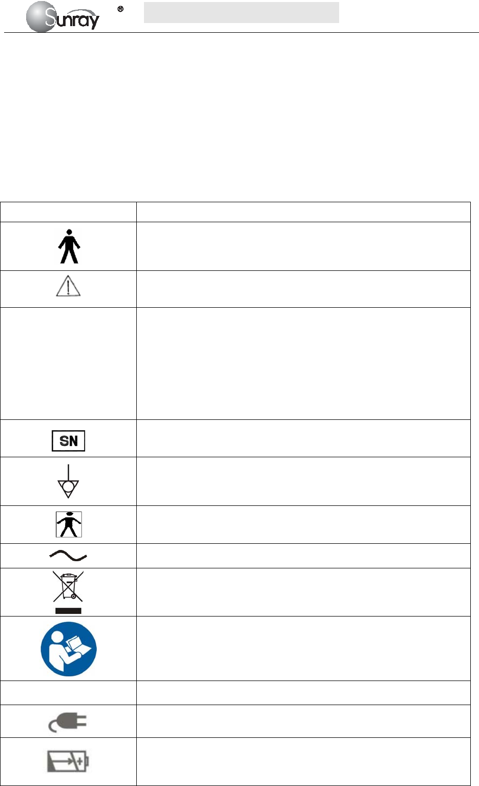
Symbol Symbol description
Type B Applied Part
Caution
IP68
This symbol is located on the FHR (Doppler ultrasound) transducer and
the uterine contraction pressure transducer, indicating that this transducer
is waterproof device. Waterproof device: Impervious to or unaffected by
water. The Transducer can work normally in the one-meter deep water for
an hour.
This symbol is located on the instrument’s protective earth terminal,
indicating an Equipotentiality symbol.
Specifies serial number
Equipotential GND
This label is on protective GND terminal of monitor, and it means
protective GND
AC
Label for electric and electronic equipment waste needing separate
disposal (please comply with requirements of local laws)
Refer to instruction manual
NET Communication port
Power indicator
Battery charging indicator
When lithium battery is charging, this indicator will be ON.

S
S
SR
R
RF
F
F6
6
61
1
18
8
8B
B
B6
6
6
U
U
Us
s
se
e
er
r
r’
’
’s
s
s
M
M
Ma
a
an
n
nu
u
ua
a
al
l
l
~5~
Power key
Press down this key to turn on monitor.
Pressing down this key for certain period will turn off monitor.
Manufacturer
S
S
SR
R
RF
F
F6
6
61
1
18
8
8B
B
B6
6
6
U
U
Us
s
se
e
er
r
r’
’
’s
s
s
M
M
Ma
a
an
n
nu
u
ua
a
al
l
l
~6~
Chapter 2 Overview of the Instrument
2.1 Expected Functions and Purposes
The SRF618B6 Fetal Monitor provides Non-Stress testing for pregnant women from the approximately 28th
week of gestation.
The SRF618B6 Fetal Monitor is intended for non-invasive monitoring of the Fetal Heart Rate (FHRs),
Uterine Activity (UA), and Fetal Movement (FM) during antepartum testing.
Information about fetal heart rate, uterine activity, and fetal movement are all displayed on the monitor and
recorded on recording paper in the form of trajectory graphic.
2.2 Configurations
This user manual is written to cover the maximum configuration. The below table list the parameters and
functions that are optional.
2.3 Overview
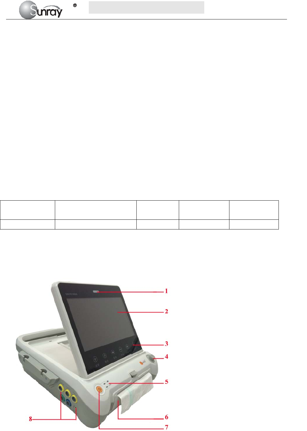
[Fig. 2-1: Front view]
Model Wireless transducers and
the holder
Monitoring
twin FHRs
Monitoring
Triplet FHRs Built-in battery
SRF618B6 Optional Optional Optional Optional
1 Alarm indicator
2 Display screen
3 Keys
4 Control knob
5 Charge, Power indicator
6 Paper drawer
7 Power key
8 Connectors (see Left Side view)
S
S
SR
R
RF
F
F6
6
61
1
18
8
8B
B
B6
6
6
U
U
Us
s
se
e
er
r
r’
’
’s
s
s
M
M
Ma
a
an
n
nu
u
ua
a
al
l
l
~7~
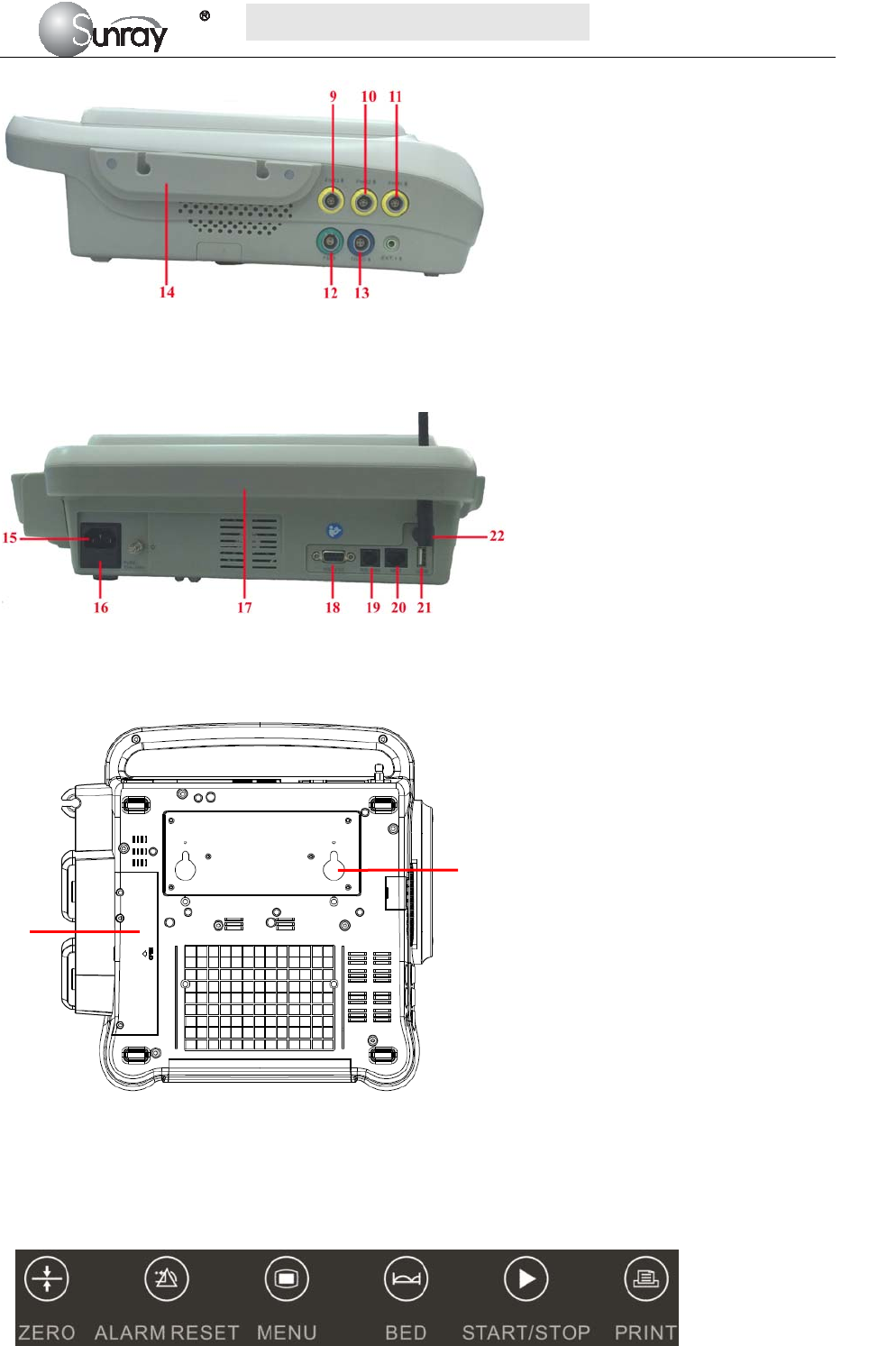
[Fig.2-2: Left side view]
[Fig. 2-3: Rear view]
[Fig. 2-4: Bottom view]
2.3.1. Keys and Control Knob
Fig. 2-5: Keys
9 FHR3 Socket
10 FHR2 Socket
11 FHR1 Socket
12 Fetal Movement Marker (FM) Socket
13 TOCO Socket
14 Wired Transducer Holder(optional)
15 Power cord connector
16 Fuse-holder
17 Handle
18 RS-232 Interface
19 RS-485 Interface
20 RJ45 Interface
21 USB Socket
22 Antenna Interface
23 Battery Component
24 Wall-mounting Holes
23
24
S
S
SR
R
RF
F
F6
6
61
1
18
8
8B
B
B6
6
6
U
U
Us
s
se
e
er
r
r’
’
’s
s
s
M
M
Ma
a
an
n
nu
u
ua
a
al
l
l
~8~
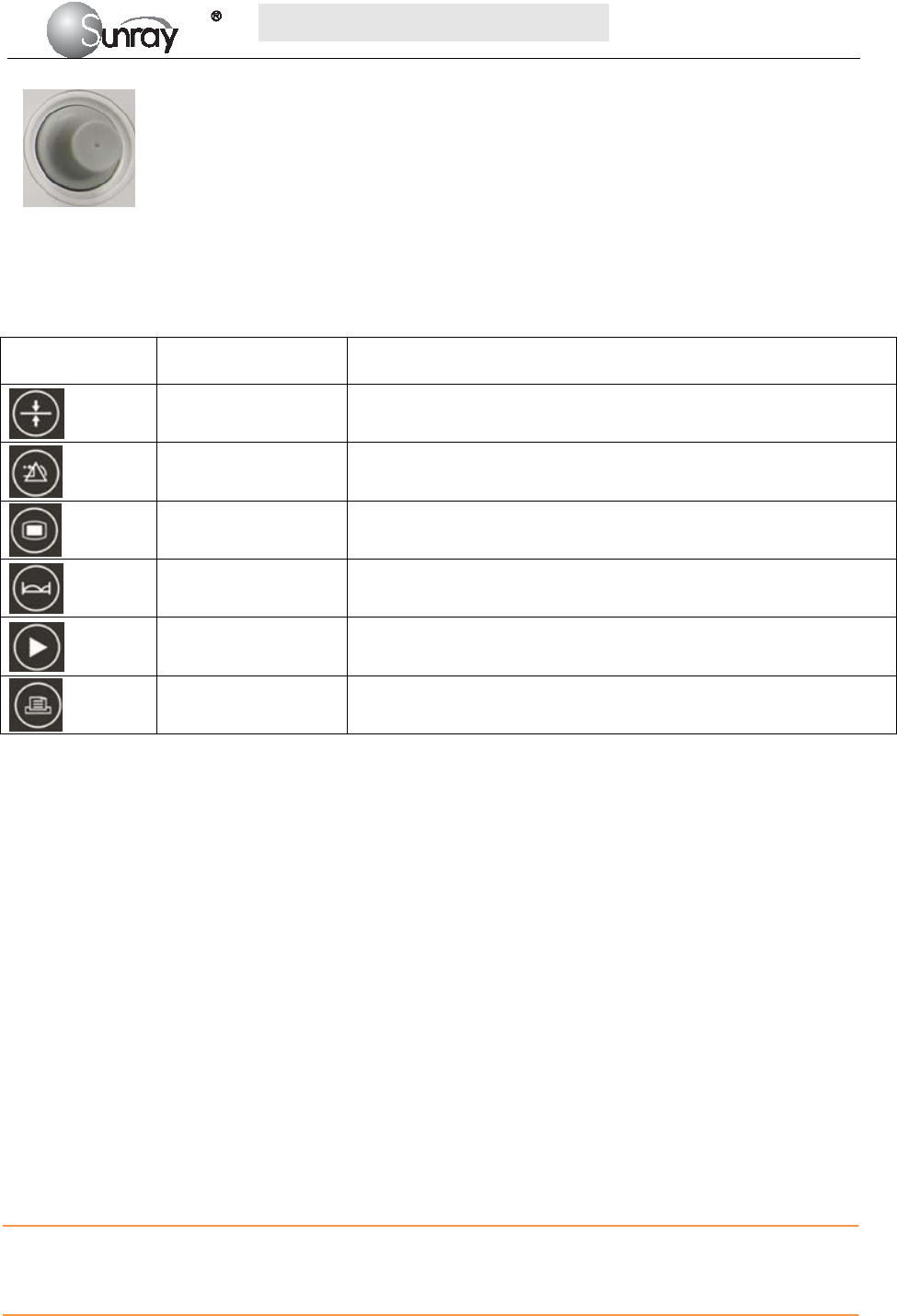
Fig. 2-6: Control Knob
The Monitor is a user-friendly device with operation conducted by a few keys on the front panel and the
control knob. Their functions are as follows.
1) Keys
Key Name Function Description
Zero key Adjust the external TOCO contractions trace/value to preset unit.
Alarm reset key Disable or enable the ALARM RESET.
Menu key Press this key to enter the main setup menu, including the Fetal
setting, System setting and so forth.
Bed key Press this key to enter the Fetal Monitoring Shortcut Menus
Start/Stop key
Start/Stop monitoring or return to the main interface. Press this key
to start monitoring or stop monitoring.
Print key Start / stop printing
Press this key to start or stop printing.
2) Control knob
Function: Adjust volume, setup and review control.
It can be pressed like other keys and be rotated clockwise or counterclockwise. All the operations on the
screen or in the menu are completed by using the control knob.
The highlighted rectangular mark on the screen that moves with the rotation of the control knob is called
“cursor”. Operations can be performed in the position on the screen where the cursor stays.
When the cursor is located on a certain item, you can press the control knob to enter its submenu or confirm
the operation. Press the control knob again, and the cursor will be able to move around on the
interface/menus.
Operation Procedure:
a) Rotate the control knob to move the cursor to the item you want;
b) Press the control knob;
c) You can rotate the control knob to select the submenu;
d) Press the control knob again, the cursor will move to the next item.
CAUTION:
This monitor is a normal medical device. Please avoid violent operations such as continuously pressing the
keys or control knob.
S
S
SR
R
RF
F
F6
6
61
1
18
8
8B
B
B6
6
6
U
U
Us
s
se
e
er
r
r’
’
’s
s
s
M
M
Ma
a
an
n
nu
u
ua
a
al
l
l
~9~
2.4 Accessories
The accessories should be connected to the monitor via the sockets on the left side and right side panels.
Each accessory has a tab on the connector housing to ensure proper insertion into the appropriate socket on
the monitor.
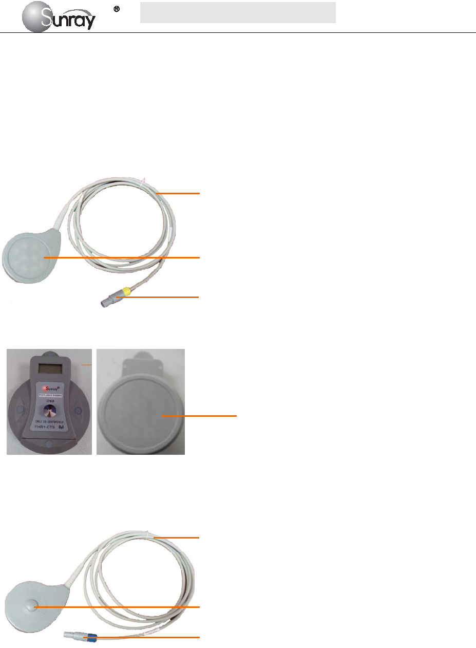
2.4.1 Ultrasound (US) Transducers
Fig 2-7: Wired US Transducer
Front view Back view
Fig 2-8: Wireless US Transducer
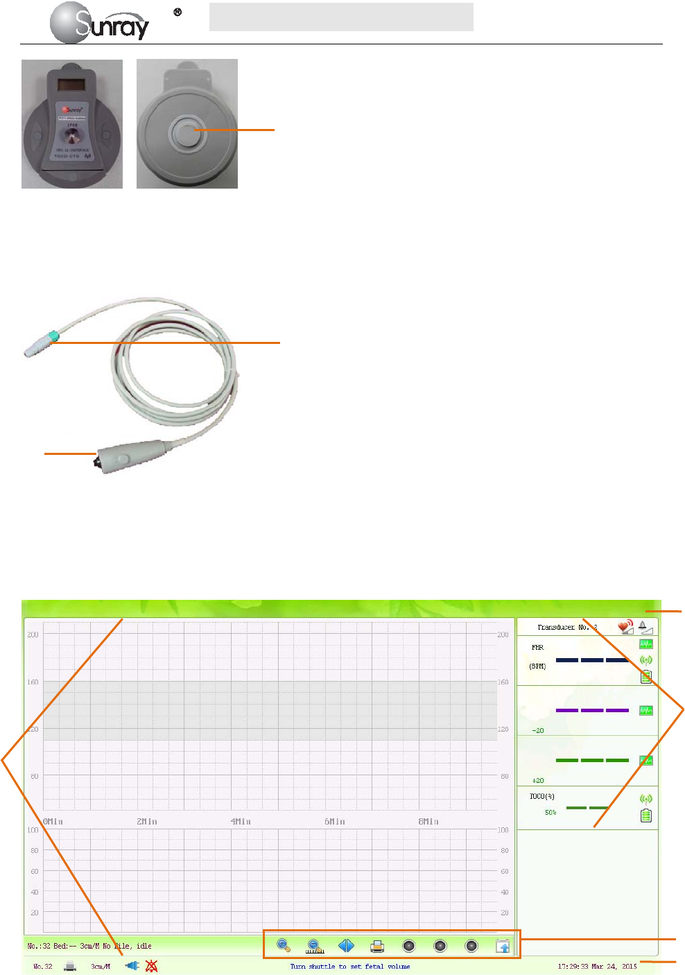
2.4.2 TOCO Transducers
Fig 2-9: Wired TOCO Transducer
1. Transducer cable
2. US Transducer Sensor
3. Transducer Connector
1
1. Transducer cable
2. TOCO Transducer Sensor
3. Transducer Connector
1
2
3
2
3
Wireless US
Transducer Sensor
S
S
SR
R
RF
F
F6
6
61
1
18
8
8B
B
B6
6
6
U
U
Us
s
se
e
er
r
r’
’
’s
s
s
M
M
Ma
a
an
n
nu
u
ua
a
al
l
l
~10~
Front view Back view
Fig 2-10: Wireless TOCO Transducer
2.4.3 Fetal Movement Marker
Fig 2-11: Fetal Movement Marker
2.5 Screen
2.5.1 Main Interface
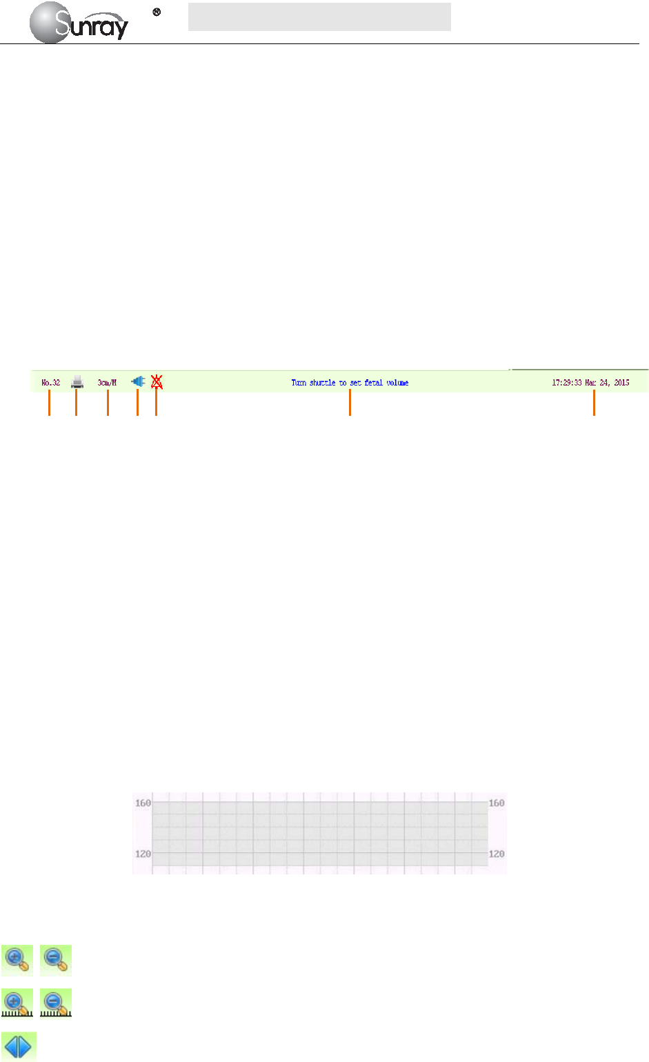
Fig 2-12: Main Interface
1. Marker Connector
2. Press key
2
3
4
1. Alarm message window 2. Numeric window
3. Status window 4. Trace/Menu window 5. Fetal monitoring shortcut menus
1
1
2
5
Wireless TOCO
Transducer Sensor
S
S
SR
R
RF
F
F6
6
61
1
18
8
8B
B
B6
6
6
U
U
Us
s
se
e
er
r
r’
’
’s
s
s
M
M
Ma
a
an
n
nu
u
ua
a
al
l
l
~11~
The main interface of the monitor displays numbers, traces, menus and monitor status information. The
screen background color has three choices: black, green and pink. To change the screen color, please refer to
the section 6.1 System setting 2) Screen Color.
According to the content, the main interface is divided into four windows: (1) Alarm Message Window (2)
Numeric Window (3) Status Window (4) Trace/ Menu Window.
1) Alarm Message Window
Alarm messages displaying area. When an alarm is active, the message will be displayed here. Physiological
alarms will be displayed on the left and technical alarms in the center.
2) Numeric Window
The fetal monitoring numerics are displayed here.
3) Status Window
4) Trace/Menu Window
The trace/menu window occupies most space of the screen. During monitoring or reviewing, it displays
traces; during setting, it displays setup menus.
The background pane bar supports two standards: 30 ~ 240 (American standard) and 50 ~ 210 (International
standard).
The grey band in between the fetal heart rate panes indicates the preset alarm range (the top edge is not
higher than 160 and the bottom edge is not lower than 110). It makes it easy to observe if the FHR exceeds
the normal range. So you can easily tell if the fetal heart rate is too low or too high.
5) Fetal monitoring shortcut menus
Besides, some other symbols appear among the traces:
Zoom in or out
Increase or decrease the FHR traces speed on the scree
Show the traces on the screen forth or back
a) Bed No.
b) Print
c) FHR traces speed on the screen
d) Power indication status
e) Alarm status
f) Operation prompt information
g) System date/time
a b c d e f g
S
S
SR
R
RF
F
F6
6
61
1
18
8
8B
B
B6
6
6
U
U
Us
s
se
e
er
r
r’
’
’s
s
s
M
M
Ma
a
an
n
nu
u
ua
a
al
l
l
~12~
Print
Turn on the Voice for FHR
Turn off the Voice for FHR
Tools menu, including the submenus of Patient information, Record List, Alarm list and Analysis
result
2.6 Ordering Information
Repair parts, along with part numbers, are listed in the tables that follow.
Description Part No.
Monitor:
Power Supply Assembly P4902-03017
Loudspeaker Assembly P4501-08019
Stepper Motor Assembly P4909-03006
Bottom Housing Assembly P2226-04004
Top Cover Housing P2226-04003
Display Assembly P4603-16026
Paper Drawer Assembly P2263-04026
Main CPU Board P1226-02031
Power Cord P5301-00011
Fuse T2AL250V P4904-00004
Rechargeable Lithium-ion Battery of the equipment P4901-01014
Transducers:
Wired Ultrasound Transducer P1221-05031
Wired TOCO Transducer P1224-05040
Wired Fetal Movement Marker P1221-12003
Wireless Ultrasound Transducer P1271-05021
Wireless TOCO Transducer P1271-02055
Rechargeable Lithium-ion Battery of the wireless transducer P4901-01013
Accessories:
Aquasonic Coupling Gel (0.25ltr bottle) P7001-00030
Paper for Recorder(30-240 FHR Scale) P8105-00004
Paper for Recorder(50-210 FHR Scale) P8105-00003
The parts employed by the manufacturer, such as the rechargeable battery, are products have the
characteristics specified by their manufacturers. The materials with which the patient or any other person can
come into contact conform with the standard of ISO 10993.

S
S
SR
R
RF
F
F6
6
61
1
18
8
8B
B
B6
6
6
U
U
Us
s
se
e
er
r
r’
’
’s
s
s
M
M
Ma
a
an
n
nu
u
ua
a
al
l
l
~13~
CAUTION
Replacement of all above accessories can be performed by the operator. But only the accessories supplied or
recommended by the manufacturer are allowed connected to the monitor.
S
S
SR
R
RF
F
F6
6
61
1
18
8
8B
B
B6
6
6
U
U
Us
s
se
e
er
r
r’
’
’s
s
s
M
M
Ma
a
an
n
nu
u
ua
a
al
l
l
~14~
Chapter 3 Installation Guide
NOTE:
Installation must be carried out by qualified personnel authorized by the manufacturer.
3.1 Unpacking and checking
1) Unpack all external packing for the monitor and its accessories.
2) Check all items according to the Packing List.
3) Check the monitor and its accessories for any damage.
4) If any item is missing or damaged, please contact the consignment unit and our company.
3.2 Installing Battery
WARNING:
Switch off the monitor and unplug it before installing or removing the battery.
If your monitor has been configured with a rechargeable lithium-ion battery, follow these steps to install the
battery:
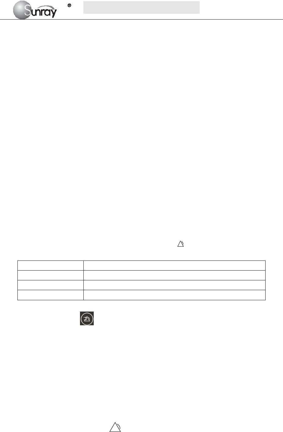
1. Battery Installation
1) Carefully place the monitor upside down on a flat surface covered with cloth or other type of
protecting pad.
2) Remove the screws of the battery compartment using a cross-head screw driver. Remove the
battery compartment cover, and take out the case 1(“1”, shown as Fig.3-1).
3) Plug the battery (2) to the case 1, and then put it into the battery compartment.
4) Shut the battery compartment cover and fix the screws.
Fig.3-1
2. Battery Removal
Fold the LCD display completely flat before turning the monitor upside down. Remove the battery in reverse
order.
NOTE:
If a rechargeable battery is outfitted, charge it fully each time after using the device to ensure the electric
power is enough.
1
2

S
S
SR
R
RF
F
F6
6
61
1
18
8
8B
B
B6
6
6
U
U
Us
s
se
e
er
r
r’
’
’s
s
s
M
M
Ma
a
an
n
nu
u
ua
a
al
l
l
~15~
When the battery configuration is provided, after the device is transported or stored, the battery must be
charged. Connecting to power supply will charge the battery no matter if the monitor is powered on.
3.3 Installation
The monitor can be placed on a flat surface, or be installed on a wall or a trolley. The service engineer should
install the monitor properly.
NOTE:
When you use this instrument you shall keep a certain distance (more than 300mm) away from other
equipment around, so as to ensure the convenience and safety of the use of this instrument.
3.4 Connecting Power Cable
1) Make sure the AC power supply of the monitor complies with the following specification: 100V-240V,
50Hz/60Hz.
2) Apply the power cable provided with the monitor. Plug one end of the power cable to the power socket
of the monitor. Connect the other end to a three-slot power output special for hospital usage.
3) The equipotential grounding terminal is provided for the connection of a potential equalization
conductor. Therefore, it is recommended to connect the grounding terminal of the monitor and the
power outlet with the grounding wire, making sure the monitor is grounded.
WARNING:
If the protective grounding (protective earth) system is doubtful, the power of the monitor must be supplied
by inner power only.
NOTE:
1) Make sure the monitor and the power outlet are placed at a place where it is easy to connect and
disconnect the power cord.
2) When the supply mains is interrupted, the device switches to inner power and operates normally if the
battery is installed. If the battery is not installed, the monitor shuts down and resumes the previous
settings at the subsequent operation.
S
S
SR
R
RF
F
F6
6
61
1
18
8
8B
B
B6
6
6
U
U
Us
s
se
e
er
r
r’
’
’s
s
s
M
M
Ma
a
an
n
nu
u
ua
a
al
l
l
~16~
Chapter 4 Alarm
4.1 Alarm classification
The monitor has two types of alarm: physiological alarm and technical alarm.
Physiological alarms indicate the situation of vital sign exceeding its configured limit. They can be
disabled. The adjustable alarm limits determine the conditions that trigger the alarm.
Technical alarms indicate that the monitor cannot measure and therefore cannot detect critical patient
conditions reliably. They cannot be disabled.
Both physiological alarm and technical alarm include visual alarm indication and audible alarm
indication.
In terms of severity, the alarms are divided into three levels: high, medium and low. High level alarm
indicates the condition where the patient’s life is endangered; it is a severe warning, labeled with the
symbol ***; Medium level alarm is a moderate warning, labeled with the symbol **; low level alarm is
labeled with the symbol *.
The high level alarms have highest priority, and the medium level alarms take the second place. If more
than one type of alarms is active at the same time, the monitor sounds an audible indicator for the higher
level alarms.
4.2 Audible Alarm
If the audible alarm is not disabled, the alarm indicator displays . When an alarm is active, the monitor
gives out a sound. (The sound pressure range is 45dB ~ 85dB.)
Alarm Category Audible Alarm Tones
High Level alarm DO-DO-DO--DO-DO---DO-DO-DO--DO-DO, 1 time/14sec
Medium Level alarm DO-DO-DO, 1 time/20sec
Low Level alarm DO-DO, 1 time/25sec
Press the Alarm reset key , it will enable or disenable the Alarm Reset function. After activation of
the Alarm Reset function, the alarm system and alarm signals behave as follow:
The auditory alarm signals of current alarm conditions cease, enabling the alarm system to respond
to a subsequent Alarm Condition.
Visual alarm signals for any existing alarm conditions continue as long as those alarm conditions
exist.
The alarm system is enabled immediately to respond to a subsequent alarm condition.
The visual alarm signals of Technical Alarm Conditions cease as long as the technical alarm
condition exists.
The normal alarm condition symbol (flashing) will be shown in the Status Window.
1) Changing the Alarm Tone Volume:
Only the authorized person with the ID and password could change the alarm volume,
S
S
SR
R
RF
F
F6
6
61
1
18
8
8B
B
B6
6
6
U
U
Us
s
se
e
er
r
r’
’
’s
s
s
M
M
Ma
a
an
n
nu
u
ua
a
al
l
l
~17~
a) Select the MENU key on the main interface.
b) Select System Setting > Login.
c) Enter the ID and password, and Confirm
d) Select Alarm volume with the numeric or OFF.
e) Select Save.
When the alarm volume is off, the alarm Audio Off symbol (flashing) will be shown in the Status
Window.
WARNING:
Auditory alarm signal sound pressure levels, which are less than ambient levels, can impede operator
recognition of alarm conditions and the alarm system provides.
4.3 Visual Alarm
When an alarm is active,
Alarm indicator: the alarm indicator lights up:
Alarm Category Indicator Color Flashing Frequency
High Level alarm red flashes quickly in red
Medium Level alarm yellow flashes slowly in yellow
Low Level alarm yellow turns yellow without flashing
Alarm message: the alarm message appears in the message window of the main interface in red or
yellow.
When more than one alarm is active, the alarm messages appear in the same area in
succession.
The physiological alarm messages are: in text form, for example “FHR1: too Low”
The technical alarm messages are displayed in text form, for example “FHR1: Transducer
Off”.
4.4 Reviewing Alarms
An alarm list file records a list of physiological and technical alarm messages for one patient with date
and time information. The Alarms record for one patient archive contains a list of up to 8000 of the most
recent alarms with date and time information.
1) For the current monitoring patient
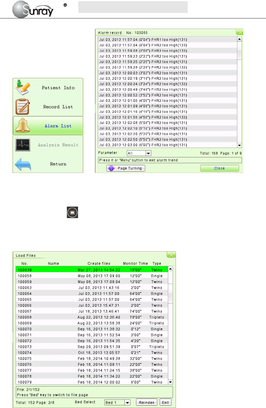
When monitoring, you can press the Bed key and rotate the control knob to select the Tools
menu key , press the control knob and enter the shortcut menu, shown as Fig.4-1. Select the Alarm
List item and enter the Alarm List menu to review alarms, shown as Fig.4-2.
S
S
SR
R
RF
F
F6
6
61
1
18
8
8B
B
B6
6
6
U
U
Us
s
se
e
er
r
r’
’
’s
s
s
M
M
Ma
a
an
n
nu
u
ua
a
al
l
l
~18~
Fig.4-1 Fig. 4-2
2) For the patient file
Press the MENU key on the main interface, you may enter the setting interface. Rotate the control
knob until the cursor on the Load Files, and press the control knob, you may enter the files listed,
shown as Fig.4-3. Select the No. you want, and then you can review the traces. And then follow the
steps in section 4.4, point 1), you can review the alarm record for this patient.
Fig.4-3
4.5 Alarm Treatment Measures
During monitoring, make sure there is at least one physician in the area where the alarm sound can be

S
S
SR
R
RF
F
F6
6
61
1
18
8
8B
B
B6
6
6
U
U
Us
s
se
e
er
r
r’
’
’s
s
s
M
M
Ma
a
an
n
nu
u
ua
a
al
l
l
~19~
heard or the alarm messages can be seen, so necessary measures can be taken when an emergency
occurs.
When the monitor gives out an alarm and catches your attention, you should:
Check the patient’s condition.
Identify the cause of the alarm.
Silence the alarm if necessary.
Check if the alarm is terminated when the alarm condition is solved.
When the monitored parameter(s) come(s) back within the adjusted limits, or if the abnormal technical
condition does not exist any longer, the monitor stops giving out the alarm.
For alarm information about each parameter, see section about corresponding parameter in this
instruction.
Note: when alarm occurs, inspect status of patient first.
4.6 Testing Alarms
Under normal case, following procedure can be used to detect visual and audible alarm:
1) Enable alarm.
2) Set the alarm limits.
3) Stimulate a signal that is higher than the upper limit or lower than the lower limit. Or
disconnect one of the plugs.
4) Verify if audible and visual alarm are functioning normally.
For example, if it is required to test FHR alarm:
1) Connect ultrasonic probe to ultrasonic probe socket.
2) Enable FHR alarm.
3) Set alarm upper limit and delay to 150 bpm and 60s respectively, and set alarm lower limit
and delay to 110 bpm and 60s respectively.
4) Stimulate FHR signal about 180 bpm (3 pulses per second), and maintain it for at least 1
minute.
5) Inspect operating condition of audible and visual alarm.
4.7 Physiological Alarm Defaults
When the patient’s monitoring physiological value is out of the limitation, the Physiological Alarm will
work. The physiological alarm default setting and limitation are as the below:
Alarm Setting Options Default
FHR Alarm On, Off On
FHR Low Limit 30~239 bpm 120 bpm
FHR High Limit 31~240 bpm 160 bpm
Alarm Sound OFF, level 1, 2, 3, and 4 Level 1

S
S
SR
R
RF
F
F6
6
61
1
18
8
8B
B
B6
6
6
U
U
Us
s
se
e
er
r
r’
’
’s
s
s
M
M
Ma
a
an
n
nu
u
ua
a
al
l
l
~20~
FHR Alarm Delay 0~300 second(s), in increments of 5 5 seconds
NOTE:
You can not disable physiological alarm and change the limitation without password. This senior
function is only for service or maintenance.
4.8 Alarm information
4.8.1 Fetus monitor specific alarm information and prompt information
Physiological alarm:
Alarm message Alarm condition Alarm level
(Bed1/2) FHR1: too High FHR measurement value is higher than preset alarm upper limit High
(Bed1/2) FHR2: too High FHR measurement value is higher than preset alarm upper limit High
(Bed1/2) FHR3: too High FHR measurement value is higher than preset alarm upper limit High
(Bed1/2) FHR1: too Low FHR measurement value is lower than preset alarm lower limit High
(Bed1/2) FHR2: too Low FHR measurement value is lower than preset alarm lower limit High
(Bed1/2) FHR3: too Low FHR measurement value is lower than preset alarm lower limit High
Technical alarm:
Alarm message Alarm condition Alarm level
FHR1:Transducer Off Fetal heart probe is detached from patient or monitor Low
FHR2:Transducer Off Fetal heart probe is detached from patient or monitor Low
FHR3:Transducer Off Fetal heart probe is detached from patient or monitor Low
US1/ US2/ US3 signal loss FHR1, FHR2 or FHR3 signal is too weak for the system to analyze. Low
Signals Overlap (FHR1, FHR2,
FHR3)
US transducer 1, US transducer 2 and US transducer 3 are aimed at
the same fetal heart; the signals overlap.
Low
4.8.2 System specific alarm information and prompt information
Technical alarm:
Alarm message Alarm condition Alarm level
System: Low Battery The battery power is too low to support further work of the
monitor.
High
Printer: Not Ready Door of recorder is not closed Low
Printer: No Paper Paper missing in printer Low
Printer: Unknown Error Unknown printer error High
S
S
SR
R
RF
F
F6
6
61
1
18
8
8B
B
B6
6
6
U
U
Us
s
se
e
er
r
r’
’
’s
s
s
M
M
Ma
a
an
n
nu
u
ua
a
al
l
l
~21~
Chapter 5 Printing
5.1 Function Description
Only the recorder paper provided by Sunray could be used in the built-in thermal recorder. It prints
continuous traces synchronously along with marks.
The monitor supports some other functions listed below:
Remaining time indicating: If the printing timer is set, a process indicator appears in the status
window after printing starts, with the remaining time shown in it.
Wider paper used.
When the time is up, the monitor gives three “Do” tones and flashes the indicator.
Fast printing: The recorder prints the data saved in the monitor at a high speed (up to 75mm/s).
Data Caching: When the paper drawer runs out of paper or when it is open, the recorder stops
printing. The data from this time on (at most 60 minutes) will be temporarily saved in the internal
memory. When new paper is loaded and/or the drawer is closed, the saved data will be printed out
at a high speed. When the saved trace has been printed out, the recorder switches back to continue
printing the current data at the normal speed automatically.
NOTE:
1) When the monitor is switched off, the data in the internal memory will be lost.
2) If a printing timer is set, and the time is out when the paper runs out, the CTG analysis result
may disaccord with the printout. Therefore, reload the paper in time to avoid paper lack.
FHR2 and FHR3 offset: You can set the offset of the FHR2 and FHR3 traces to separate the three
FH traces on the screen and the recorder paper. Refer to 6.2 4) FHR Trace Separation.
Print self-check: The recorder prints a test page for self checking when you select the Print Test
Page on the Printer Setting menu.
5.2 Loading Recorder paper
If the monitor is used for the first time or when the paper runs out, you should load paper.
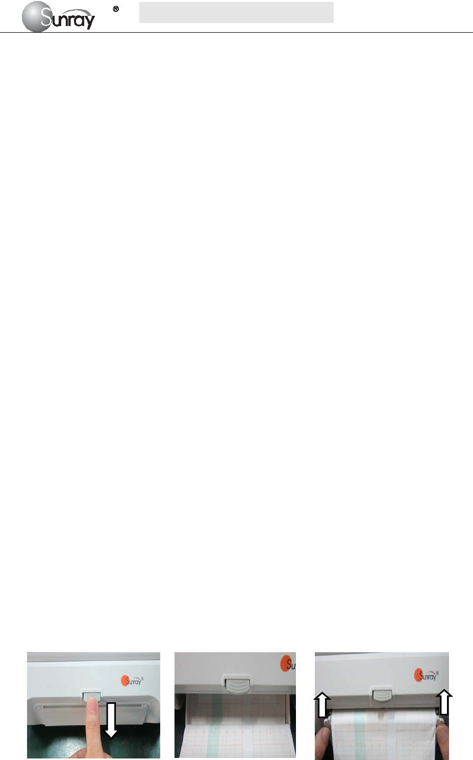
1) Turn on the power key.
2) Press the Paper Eject Button to open the paper drawer, as shown on Fig.5-1.
3) Unfold the top page of a loading paper, place the “SUNRAY CO., LTD.” marking to the left, and
then slide the paper into the paper drawer. Pull the top page of the loading paper out of the drawer,
as shown on Fig.5-2.
4) Close the recorder cover ,as shown on Fig.5-3
Fig.5-1 Fig.5-2 Fig.5-3
S
S
SR
R
RF
F
F6
6
61
1
18
8
8B
B
B6
6
6
U
U
Us
s
se
e
er
r
r’
’
’s
s
s
M
M
Ma
a
an
n
nu
u
ua
a
al
l
l
~22~
5.3 Choosing Paper Speed
You can choose a paper speed of 1 cm/min, 2cm/min or 3cm/min:
1) Select the MENU key on the main interface.
2) Select System Setting > Printer Settings>CTG Print Speed.
3) Select 1 cm/M, 2 cm/M or 3 cm/M (default).
4) Select Save.
NOTE:
Different paper speed setting causes different FHR trace appearance on the record paper. To avoid
misinterpretation, we recommend you to set all monitors in your institution to the same paper speed.
5.4 Print Self-Check
You can print a self-check as below:
1) Select the MENU key on the main interface.
2) Select System Setting > Printer Settings.
3) Select Print Test Page.
5.5 Select the printing range
1) Press the Bed key to select the current patient, or load the patient file (refer to section 8.9
Reviewing)
2) Rotate the control knob to select the print menu , and perss the control knob and enter to select the
printing range.
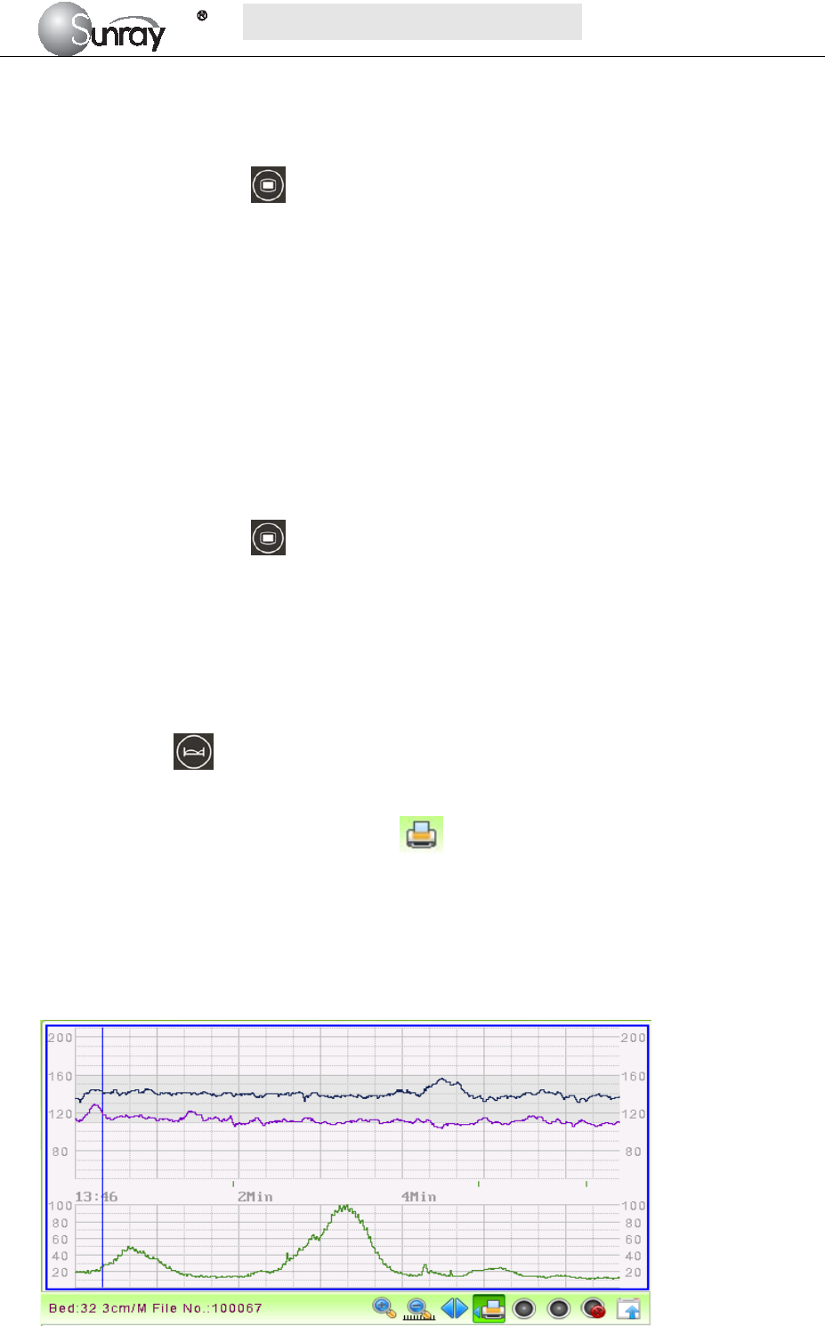
3) Select the printing start time:
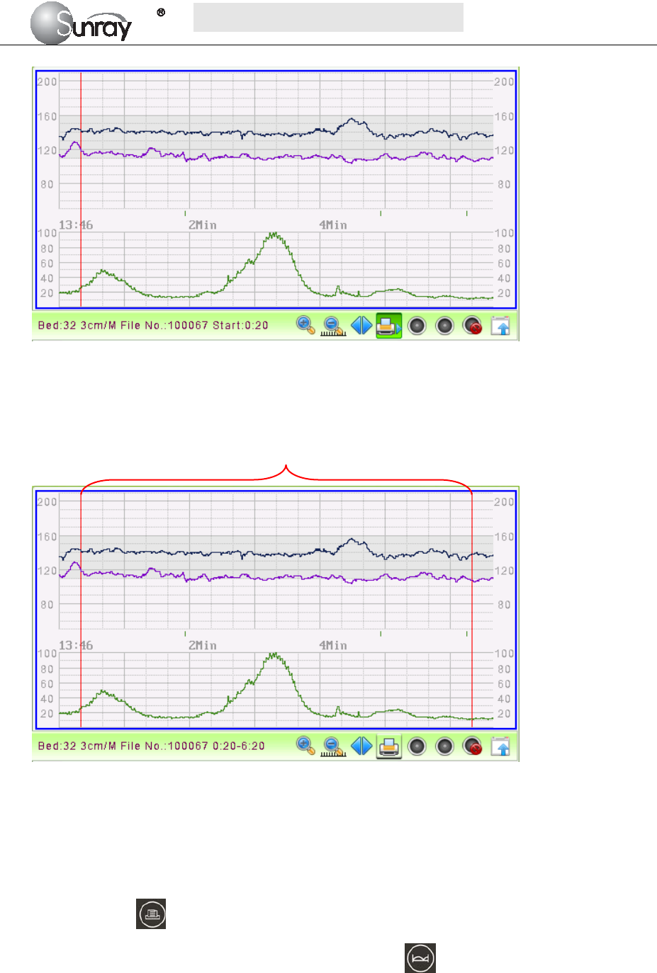
Press the control knob, it will show a blue line (see the Fig.5-4). Rotate the control knob, and the blue
line will be backward or forth. Press the control knob to confirm the printing start time. The blue line
will turn to red (see the Fig.5-5).
Fig.5-4
S
S
SR
R
RF
F
F6
6
61
1
18
8
8B
B
B6
6
6
U
U
Us
s
se
e
er
r
r’
’
’s
s
s
M
M
Ma
a
an
n
nu
u
ua
a
al
l
l
~23~
Fig.5-5
4) Select the printing end time:
Repeat the operation in step 3) to select the printing end time. The range between the two red lines is the
selected printing range.
Fig.5-6
5.6 Print the traces
1) For the patient being monitored,
Print the selected range: You can select the printing range (refer to section 5.5), and then long press
the print key , it will print the selected range.
If you don’t select the printing range, press the Bed key and then long press the print key, it
will print the traces after the monitoring time you press the print key. If you have set the print time,
it will print for the pre-set time period.
2) For loading the patient file,
Print the selected range: You can select the printing range (refer to section 5.5), and then long press
Printing range
S
S
SR
R
RF
F
F6
6
61
1
18
8
8B
B
B6
6
6
U
U
Us
s
se
e
er
r
r’
’
’s
s
s
M
M
Ma
a
an
n
nu
u
ua
a
al
l
l
~24~
the print key , it will print the selected range.
If you don’t select the printing range, long press the print key, it will print the completed traces. If
you have set the print time, it will print for the pre-set time period.
During printing, you can long press the print key to stop the printing.
5.7 Understanding Recorder Paper Printout
WARNING:
1) If there is any discrepancy between the display and the printout, the printout should prevail.
2) If the data is doubtful, clinicians should make diagnoses based on the real condition.
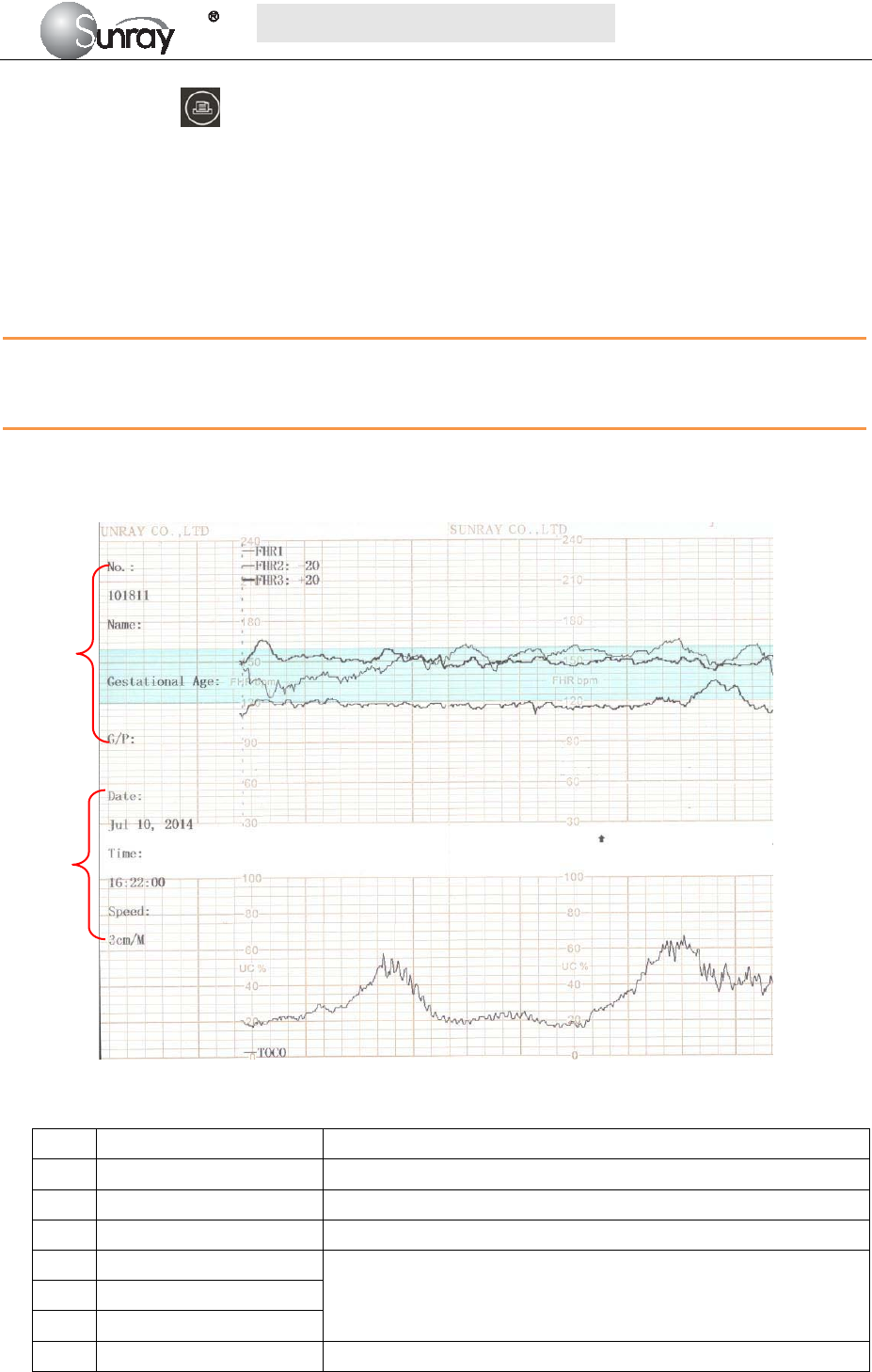
Fig. 5-7 is an example of the recorder paper with traces. Comparing it with the monitor screen, you can find
this extra information on it:
Fig. 5-7An example of recorder paper with traces
Item Information Description
1 Patient information Patient information list, including the No., Name etc.
2 Trace Information List A list of current date, time, print speed
3 FHR Mark FHR1, FHR2 offset, and FHR3 offset.
4 FHR3 trace The traces marked with “FHR” are the FHR traces. The most
thickness one is FHR3 trace, the moderate one is FHR2 trace, and
the most thinness is FHR1 trace.
5 FHR1 trace
6 FHR2 trace
7 TOCO The trace marked with “TOCO” is the TOCO trace.
1
2
3
4
5
6
7

S
S
SR
R
RF
F
F6
6
61
1
18
8
8B
B
B6
6
6
U
U
Us
s
se
e
er
r
r’
’
’s
s
s
M
M
Ma
a
an
n
nu
u
ua
a
al
l
l
~25~
5.8 Tearing Off the Paper
When recording is done, tear off the recording paper along the folding line.
S
S
SR
R
RF
F
F6
6
61
1
18
8
8B
B
B6
6
6
U
U
Us
s
se
e
er
r
r’
’
’s
s
s
M
M
Ma
a
an
n
nu
u
ua
a
al
l
l
~26~
Chapter 6 Settings
What the monitor displays, and the way it operates, is controlled by its settings. All settings can be
conducted by a few keys on the front panel and the control knob. They determine screen content, layout,
high and low alarm limits and so forth. Please refer to section 2.2.1 for the keys and control knob.
Press the MENU key on the main interface, you may enter the setting interface, as shown in the
Fig6-1. Rotate the control knob until the cursor on the setting item you want, and press the control knob,
you may enter the Fetal Settings, or System settings.
Fig.6-1
To confirm the setting changes in the submenus, you need to select SAVE to exit. If you don’t want to
store the new settings, select CANCEL, or press the MENU key to return to the main interface. Or
you may select DEFAULT to use the default settings.
Once you select SAVE to confirm the setting changes, the new settings will be stored in the monitor’s
long-term memory. If the monitor is switched on again after being switched off or a power loss, it will
restore the new settings. The setting does not take effect if the system exits automatically or is shutdown
before SAVE is selected.
6.1 System setting
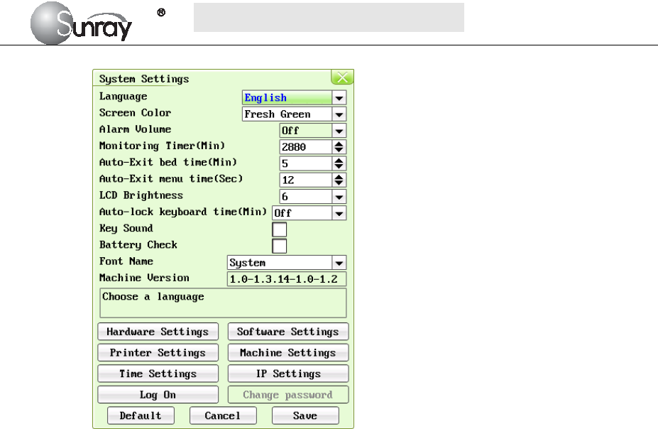
The system setting interface, is as shown in the Fig.6-2.
S
S
SR
R
RF
F
F6
6
61
1
18
8
8B
B
B6
6
6
U
U
Us
s
se
e
er
r
r’
’
’s
s
s
M
M
Ma
a
an
n
nu
u
ua
a
al
l
l
~27~
Fig.6-2
The system setting parameters are as follows:
1) Language : there two options, Chinese and English;
2) Screen Color: the screen background color has three choices: classic black, fresh green, and
warm pink;
3) Alarm Volume: OFF, 1, 2, 3, and 4 adjustable.
Note: if alarm volume setting is “OFF”, no audible alarm will be issued when any alarm
occurs. Only the authorized person with the ID and password could change the alarm
volume. Refer to 18) of this section for the Login of authorized ID. After login, you can
change the alarm volume.
4) Monitoring Timer (Min): the elapsed time for each monitoring, range from 10min to2880min
adjustable.
5) Auto-Exit bed time (Min): The lasting time for the selected bed as the current bed. After this
time it will exit automatically. The lasting time range from 1 to 20 min adjustable. “0” means
that this function is not enabled.
6) Auto-Exit menu time (Sec): The Menu interface lasting time when no operation is performed.
After this time it will exit automatically. The lasting time range from 10s to 60s adjustable.
“0” means that this function is not enabled.
7) LCD Brightness: LCD screen brightness levels, level 1~8
8) Auto-lock keyboard time(Min): Off, 1 Min, 2 Min, 5 Min adjustable
Note: “Off” means that keyboard lock function is not enabled. For a fixed time, it means
the auto-lock function will be active when a user does not make any operations in a fixed
time. The device also has a manual lock function that long pressing the Menu key will
unlock or lock the keyboard.
9) Key Sound: If the key sound is enabled, the monitor gives a normal key sound when the
operation is valid, and gives a sharp “Di” sound when the operation is invalid.
10) Battery Check: If the battery check is enabled, the monitor will check whether the battery of
the main machine is in good condition when the monitor is on.
11) Font Name: Times New Roma, Arial, Calibri, Tahoma, Terminal, MS Sans Serif, Courier New
S
S
SR
R
RF
F
F6
6
61
1
18
8
8B
B
B6
6
6
U
U
Us
s
se
e
er
r
r’
’
’s
s
s
M
M
Ma
a
an
n
nu
u
ua
a
al
l
l
~28~
and System available.
12) Machine Version: this function is only used by maintenance person authorized by
manufacturer.
13) Hardware setting: this function is only used by maintenance person authorized by
manufacturer.
14) Software setting: this function is only used by maintenance person authorized by
manufacturer.
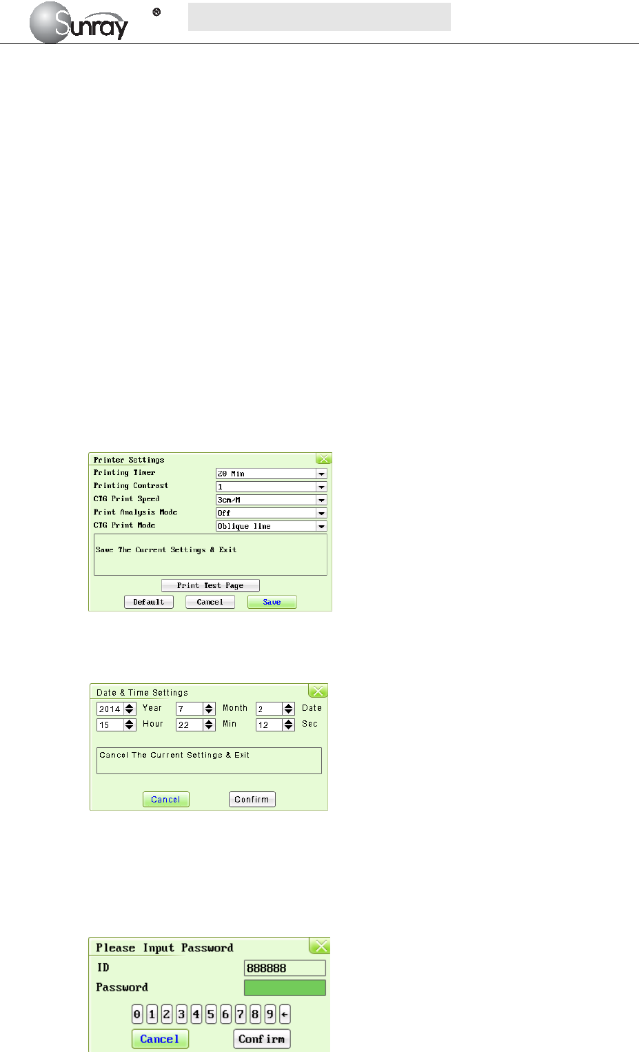
15) Printer Settings: select the Printer Settings, and enter the printer submenu, see Fig.6-3.
Printing Timer: The printing timer determines the elapsed time for each print. Off, 10min,
20min, 30min, 40min, 50 min, 60 min, and 120 min available. For a fixed time, the
recorder stops when the time is up. For Off, there is no time limit. Or you can select the
printing range to print the traces range you want (refer to section 5.5). Whatever the
setting is, the recorder stops when this patient’s traces come to the end or if the PRINT
key is pressed in midway.
Printing Contrast: how dark of the printing. Five levels are available (level 1~5)
CTG Print Speed: 1cm/min, 2cm/min, 3cm/min adjustable
Print Analysis Mode:CST, NST, Krebs, Fischer, Off.
CTG Print Mode: broken line, oblique line.
Fig.6-3
16) Time Settings: select the Time Settings, and enter the system date and time submenu, see
Fig.6-5.
Fig.6-4
17) IP Setting: set up the apparatus IPV4 address
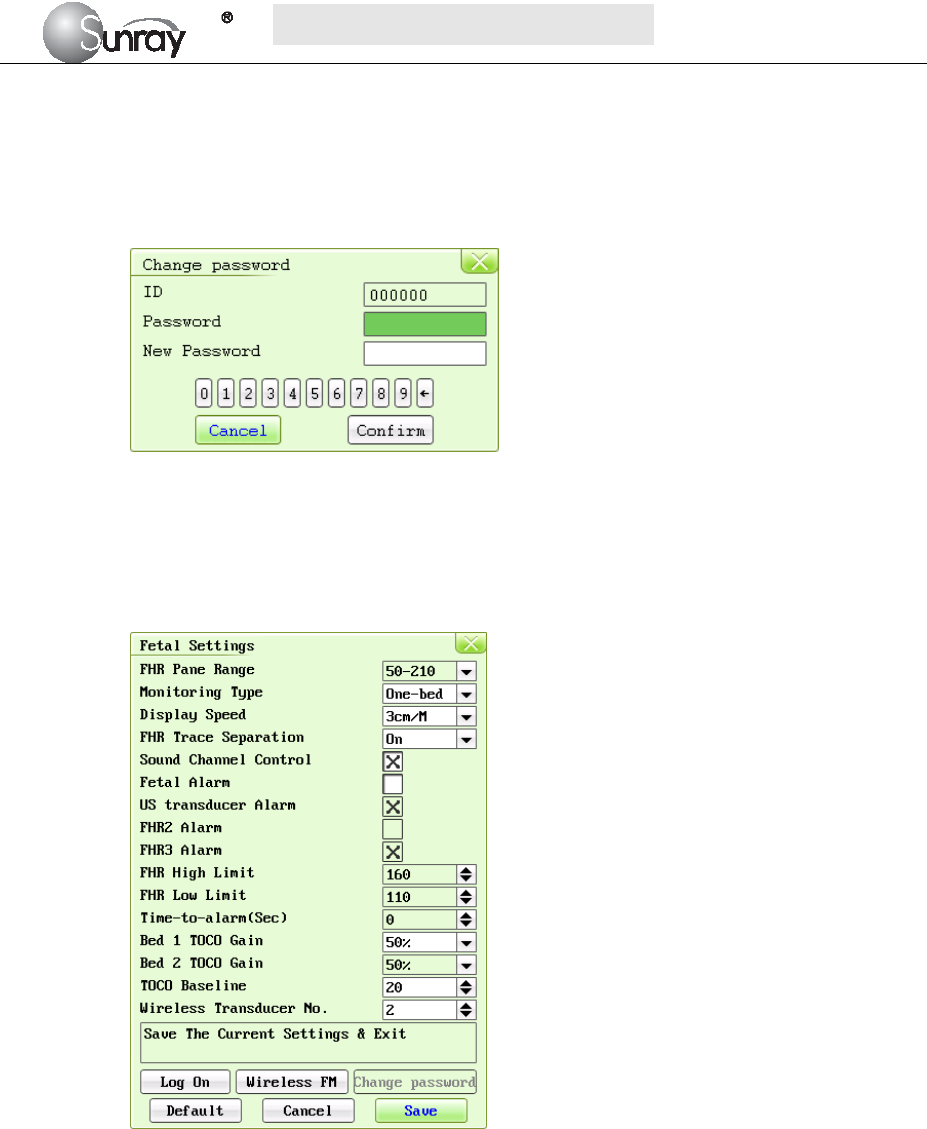
18) Log on: select the Log on, and enter the system login interface, see Fig.6-5. Input the ID and
password, and select “Confirm”. Then login the authorized setting interface, you can set the
Alarm Volume and change password.
S
S
SR
R
RF
F
F6
6
61
1
18
8
8B
B
B6
6
6
U
U
Us
s
se
e
er
r
r’
’
’s
s
s
M
M
Ma
a
an
n
nu
u
ua
a
al
l
l
~29~
Fig.6-5
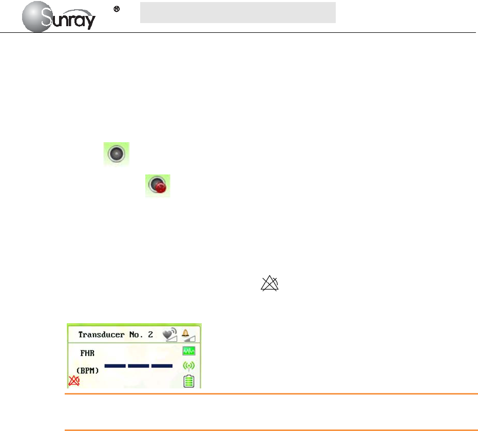
19) Change password:You can set the new password here, see Fig.6-5.
Note: Only the authorized person with the ID and password could change the password.
Refer to 18) of this section for the Login of authorized ID. After login, you can change
the password.
Fig.6-6
6.2 Fetal settings
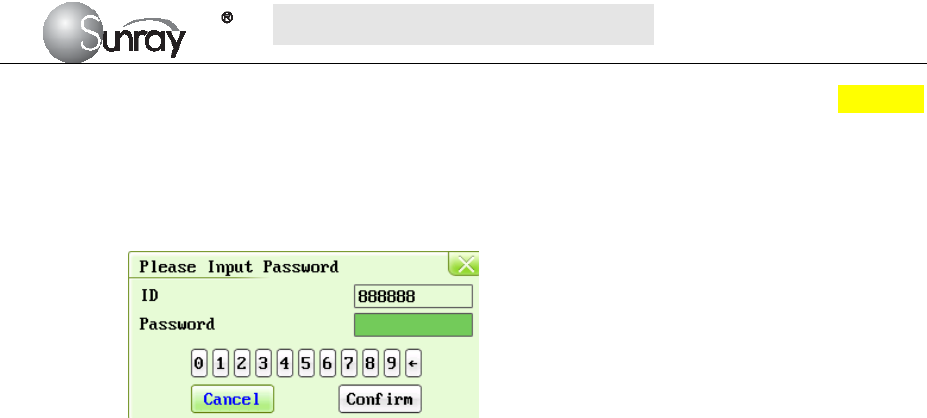
The Fetal setting interface, is as shown in the Fig.6-7.
Fig.6-7
The Fetal setting parameters are as follows:
1) FHR Pane Range: the background pane bar supports two standards: 30 ~ 240 (American
standard) and 50 ~ 210 (International standard).
Note: Only the authorized person with the ID and password could change the FHR Pane
Range. Refer to point 16) of this section for the Login of authorized ID. After login, you
can change the FHR Pane Range.
2) Monitoring Type: one-bed, two-bed.
Note: this item cannot be modified under monitoring status.
3) Display speed: the FHR traces speed on the screen: 1cm/min, 2cm/min, and 3cm/min
adjustable
4) FHR Trace Separation: You can set the offset of the FHR2 and FHR3 traces to separate the
three FHR traces on the screen and the recorder paper. When it is selected (on), to make
S
S
SR
R
RF
F
F6
6
61
1
18
8
8B
B
B6
6
6
U
U
Us
s
se
e
er
r
r’
’
’s
s
s
M
M
Ma
a
an
n
nu
u
ua
a
al
l
l
~30~
differentiating the traces easier, the trace for FHR2 is offset by -20 bpm, and the trace for
FHR3 is offset by +20 bpm. In other words, the trace for FHR2 is recorded 20 bpm lower than
it really is, while the trace for FHR3 is recorded 20 bpm higher than it really is. The trace for
FHR1 is never shifted.
5) Sound Channel Control: When is on, it can choose to turn on/off the sound of each FHR;
When is off, the function is disabled. When you turn on the sound of some FHR, the related
symbol will display in the related main screen; When you turn off the sound of some
FHR, the symbol will display in the related main screen.
6) Fetal alarm: Switching FHR Alarm on or off. When it’s selected, this function is on. Always
check if the alarm settings are appropriate for your patient before starting a monitoring. You
can choose to switch the FHR alarm on or off. If the fetal heart alarm is switched off, the
monitor will no longer give any audible or visual warning for this monitoring item.
When the alarm is off, the Alarm Off symbol is shown in the leftside of Numeric Window.
For example:
WARNING:
Do not switch the alarm off for the condition where the patient’s safety maybe endangered.
7) US Transducer alarm: determine if alarm is enabled when US transducer is not in the correct
position with the detection source.
8) FHR2 Alarm: determine if alarm is enabled when FHR2 meets alarm condition.
9) FHR3 Alarm: determine if alarm is enabled when FHR3 meets alarm condition.
10) FHR High Limit: the FHR upper alarm limit, value from 31 ~ 240 (bpm) adjustable;
11) FHR Low Limit: the FHR lower alarm limit, value from 30 ~239 (bpm) adjustable;
Note: Only the authorized person with the ID and password could change the FHR
High/Low Limit. Refer to point 16) of this section for the Login of authorized ID. After
login, you can change the FHR High/Low Limit.
12) Time-to-alarm (sec): change the time for FHR alarm delay. The alarm delay indicates how
long the measured result continues exceeding its limit before the alarm is triggered. Value
from 0~300s adjustable.
Note: Only the authorized person with the ID and password could change the
Time-to-alarm. Refer to 16) of this section for the Login of authorized ID. After login,
you can change the time for FHR alarm delay.
13) Bed 1TOCO gain: 50%, 100%, 200% adjustable;
14) Bed 2TOCO gain: 50%, 100%, 200% adjustable;
15) TOCO baseline: the TOCO baseline, 5 options: 0%, 5%, 10%, 15%, 20%;
Note: Only the authorized person with the ID and password could change the TOCO
gain and TOCO baseline. Refer to point 17) of this section for the Login of authorized ID.
Only after login, you can change the TOCO gain and TOCO baseline.
S
S
SR
R
RF
F
F6
6
61
1
18
8
8B
B
B6
6
6
U
U
Us
s
se
e
er
r
r’
’
’s
s
s
M
M
Ma
a
an
n
nu
u
ua
a
al
l
l
~31~
16) Wireless Transducer No.: from 1~16 adjustable. Before set the No., see section 8.7 Using
Wireless Transducers.
17) Log on: select the Log on, and enter the system login interface, see Fig.6-8. Input the ID and
password, and select “Confirm”. Then login the authorized setting interface, you can set the
FHR Pane Range, FHR High/Low Limit, Time-to-alarm and change password.
Fig.6-8

S
S
SR
R
RF
F
F6
6
61
1
18
8
8B
B
B6
6
6
U
U
Us
s
se
e
er
r
r’
’
’s
s
s
M
M
Ma
a
an
n
nu
u
ua
a
al
l
l
~32~
Chapter 7 Pre-monitoring Preparation
7.1 Switching On
WARNING:
1) Check if all the metal parts are linked to the protective earth cord and the cord is in good condition
before switching on the monitor.
2) If any sign of damage is detected, or the monitor displays some error messages, do not use it on any
patient. Contact biomedical engineer in the hospital or our service engineer immediately.
Press the POWER key on the top panel to switch on the monitor. The power indicator lights up and a start-up
music will be heard. You can operate the monitor after the main interface appears.
NOTE:
Make sure the paper is correctly loaded before the printing starts.
7.2 Adjusting Screen Angle
The angle between the screen and the top cover of the monitor is adjustable as needed, allowing it to be
mounted on a wall or placed on a flat surface.
Adjustment method:
Push the hook on top of the screen left to spring it open. Pull the screen forward to adjust to one of the preset
screen angles. To bring the screen back to flat, pull it all the way forward and then push it back.
7.3 Setting Date and Time
You can change the date and time of the monitor, please refer to section 6.1 16) Time settings for setting the
date and time.
CAUTION:
You should set date and time information in advance. After this information is changed, the monitor starts
new monitoring with an auto ID. Therefore, we advise you to restart the monitor after changing date or time
information, and do not perform this operation when monitoring is in process.
7.4 Connecting Transducers
Check for visible damages of the transducers every time before connecting them to the monitor.
Pay special attention to the cracks on the transducers and cables before immersing them into conductive fluid.
If damage is found, replace them with good ones at once.
When plugging transducers into the monitor, make sure the arrow symbol of the connector faces up and put it
into the socket. The connection of the transducer(s) is one-to-one correspondence. If a transducer is inserted
to a wrong receptacle, it cannot be connected correctly.

S
S
SR
R
RF
F
F6
6
61
1
18
8
8B
B
B6
6
6
U
U
Us
s
se
e
er
r
r’
’
’s
s
s
M
M
Ma
a
an
n
nu
u
ua
a
al
l
l
~33~
When disconnecting a transducer, pinch the after body of the transducer plug and pull it out slightly.
NOTE:
Never try to disconnect the transducer by pulling the cable directly.
The fetal heart rate transducer is different from the uterine contraction pressure transducer.
7.5 Placing Transducers in the Holder
In order to protect the transducers, place the not-in-use transducers in the holder. The wired transducers
holder is on the left of the front panel, and the wireless transducers holder is on the right. To place a
transducer into the holder, hold the transducer on the edge, and then place the buckle all the way into one of
the holes on the holder.
NOTE:
In the process of monitoring, the transducer that is placed in the holder may be affected and thereby produces
interfering signals. Therefore, when monitoring a patient, it is recommended to remove or disconnect the
transducer that is not in use.
7.6 Verifying Correct Installation
And now use the following method to test whether the instrument has been installed correctly and able to
work normally:
1) Wet your hand or dip a little bit of water with your hand and gently slide on the detecting surface of the
FHR transducer, then you will hear the Doppler sound issued by the instrument. If the sound is not loud
enough, you can improve it by means of increasing the sound volume, adding a little more water,
speeding up the speed of relative movement between your hand and the transducer, or fully getting in
touch with the detecting surface of the transducer.
NOTE: Please never apply too much force on the FHR transducer so as to prevent the instrument from
damaging.
2) A few minutes later the monitor will start to display the detected data. Now gently and periodically
(approximately 120BPM) touch the surface of the FHR transducer. If a Doppler sound can be heard, this
instrument should be able to detect the data of this simulated fetal heart rate.
3) Gently press the measured area of the TOCO transducer, the instrument should be able to detect the data
of this simulated uterine contraction pressure. The range of weight measured is 0~1000g, the
corresponding range of digital display is 0~100%, and the range of curve display is 0~100%. If the
pressure exceeds 1000g, saturation will occur: Corresponding digital display will be always 100%, and
curve display will be always100% too.
NOTE: Please never apply too much force on the uterine contraction pressure transducer so as to prevent the
instrument from damaging. And never let the uterine contraction pressure transducer contact with water or
ultrasound jelly or the circuit inside the transducer might be damaged.
4) Press the fetal movement marker once, the instrument should be able to detect this simulated fetal
movement signal.

S
S
SR
R
RF
F
F6
6
61
1
18
8
8B
B
B6
6
6
U
U
Us
s
se
e
er
r
r’
’
’s
s
s
M
M
Ma
a
an
n
nu
u
ua
a
al
l
l
~34~
5) Since this instrument is a monitoring type instrument, which uses an advanced and unique algorithm,
the detected fetal heart rate signal, uterine contraction pressure signal and fetal movement signal will be
delayed for approximately 3 seconds before they are displayed. This has no adverse effect on the
clinical value of this instrument, on the contrary, this will be helpful for this instrument to capture each
fetal heart beat more
NOTE: When the Doppler Transducer is put not on the back but on the breast part of fetus, accurate
ultrasonic waves cannot be caught from the fetal heart and fetal heat beat can be frequently missed.
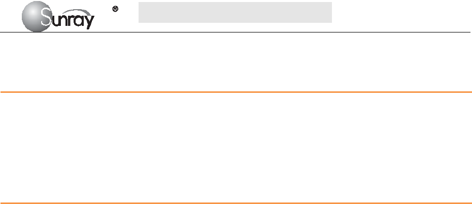
S
S
SR
R
RF
F
F6
6
61
1
18
8
8B
B
B6
6
6
U
U
Us
s
se
e
er
r
r’
’
’s
s
s
M
M
Ma
a
an
n
nu
u
ua
a
al
l
l
~35~
Chapter 8 Fetal Monitoring
WARNING:
1) Always check if the alarm settings are appropriate for your patient before starting monitoring.
2) Check for any fault of the transducers before applying them to the patient.
3) Using a mixture of wired transducers and wireless transducers is not supported. When the monitor
is used on multiple pregnant women, you can only use wired US transducers and wired TOCO
transducers on one pregnant woman, and wireless US/TOCO transducers on the other pregnant
women.
CAUTION: When the monitor is used with HF surgical equipment, the transducer and the cables must be
avoided conductive connection to the HF equipment to protect against burns to the patient.
8.1 Confirming Fetal Life
Fetal monitoring with ultrasound can’t differentiate a fetal heart rate signal source from a maternal heart rate
source in all situations. These are some of the signal sources that might be taken as FHR signal source by
mistake:
- High maternal heart rate signal.
- Maternal aorta or other large vessels signals.
- Electrical impulse from the maternal heart transmitted through a recently deceased fetus.
- Movement of the deceased fetus during or following maternal movement.
So you need to confirm fetal life by other means before starting to use the fetal monitor, such as using a
fetoscope, stethoscope, Pinard stethoscope or obstetric ultrasonography.
8.2 Monitoring FHR with Ultrasound
The ultrasound monitoring is a method to obtain FHR on maternal abdominal wall. Place a US transducer
(Ultrasound transducer) on maternal abdomen. It transmits low energy ultrasound wave to the fetal heart, and
receives the echo signal.
8.2.1 Parts Required
US transducer
Aquasonic coupling gel
Belt
8.2.2 FHR Monitoring Procedure
1) Placing Transducer Belt
Place the transducer belts around the patient, ensuring that the belt will be around the abdomen
when it is fastened. Lay the patient on the bed.
Alternatively, the patient can take a sitting position. Arrange the belt around her abdomen.
2) Determining the Transducer Position
Determine the fetal position using Leopold’s maneuvers.
Search for the location of the fetal heart using a stethoscope or a fetoscope. The best fetal
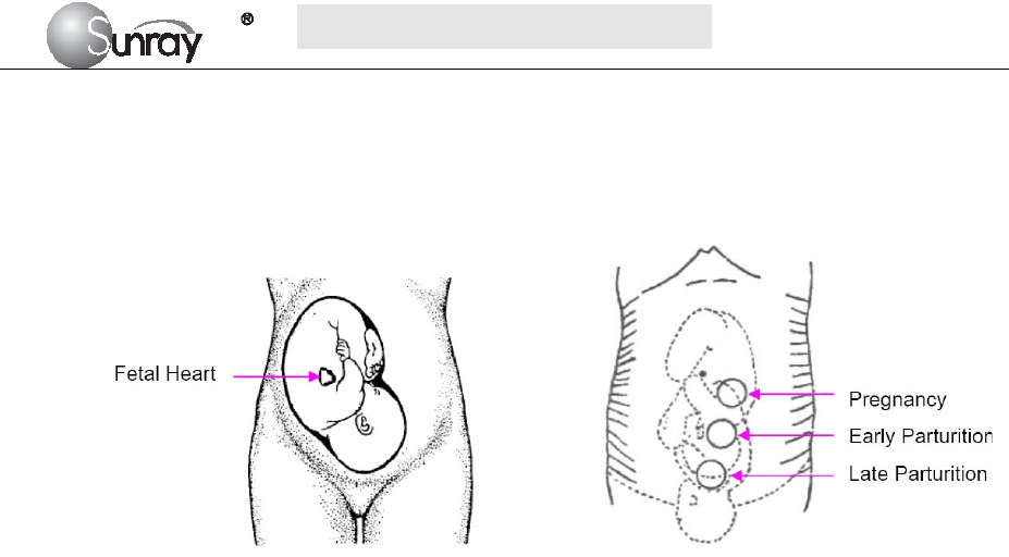
S
S
SR
R
RF
F
F6
6
61
1
18
8
8B
B
B6
6
6
U
U
Us
s
se
e
er
r
r’
’
’s
s
s
M
M
Ma
a
an
n
nu
u
ua
a
al
l
l
~36~
heart signal can be obtained through the fetal back. See the Fig.8-1 as below.
During parturition, the fetal heart moves downward as the labor progresses. It is
recommended to move the transducer along with the fetus.
Fig. 8-1 Positioning Ultrasound Transducer (single fetus)
8.2.3 Acquiring Fetal Heart Signal
Apply a certain amount of acoustic gel on the underside of the transducer and move it slowly around the
fetus site. Find at least 2 or 3 sites, and choose the one where the clearest, most sonorous and steady fetal
heart sound is heard.
8.2.4 Fixing the Transducer
Wrap the abdomen with the belt over the transducer. Fix the transducer by pushing its buckle through the
overlapping section of the belt.
Make sure the belt fits the patient snugly but comfortably. Meanwhile, fetus heart beat sound is heard; the
FHR trace and numeric are displayed. During long-time monitoring, the gel may dry out as the transducer
moves around. Add more gel in time if it is inadequate.
8.2.5 Confirming that the Fetus is the Signal Source
Ultrasound Doppler technology is utilized to observe the fetal heart rate externally, there are possibilities that
maternal heart rate signal is mistaken for FHR signal. It is highly recommended to confirm that the fetus is
the signal source continuously. You can feel the maternal pulse at the same time.
If the maternal heart signal is misidentified as the fetal heart signal, Repositioning of the transducer is
needed.
NOTE:
1) Do not mistake the high maternal heart rate for fetal heart rate. The fetal pulse can be distinguished from
the maternal pulse by feeling the mother’s pulse during the examination.
2) The best quality records will only be obtained if the probe is placed in the optimum position. Positions
with strong placental sounds or umbilical blood flow sound should be avoided.
3) If the fetus is in the cephalic presentation and the mother is supine, the clearest heart sound will
normally be found on the midline below the umbilicus. During monitoring, the patient’s prolonged lying
in the supine position should be avoided owing to the possibility of supine hypotension. Sitting up or
lateral positions are preferable and may be more comfortable.
4) It is impossible to examine FHR unless a clear fetal heart signal is detected.

S
S
SR
R
RF
F
F6
6
61
1
18
8
8B
B
B6
6
6
U
U
Us
s
se
e
er
r
r’
’
’s
s
s
M
M
Ma
a
an
n
nu
u
ua
a
al
l
l
~37~
Technical Description:
a) The fetal heart sound issued by the monitor is not the real fetal heart beating sound, and there is not
much diagnostic value with its sound quality either. Actually, the fetal heart sound issued by the monitor
is the sound signal derived from fetal heart pulse through multiple times of conversion of physical
variables of ultrasound signal and electronic signal, indicating the movement information of fetal heart
beat. This is different from the fetal heard sound heard from a stethoscope.
b) This instrument cannot be used to measure an adult’s heart rate. It is a wrong operation for an operator
to direct the fetal heart rate transducer to the pregnant woman’s heart to verify the measurement
accuracy of the monitor.
c) If the sound is found to be unclear or too low, the transducer position should be adjusted or the earth
wire checked for properly earthing; otherwise the heart rate curve may appear to be scrambled or have
multiple breakpoints.
8.3 Monitoring Twin FHRs
To monitor twin FHRs externally you need two ultrasound transducers. Follow the procedures described in
“8.2.2 FHR Monitoring Procedure” to acquire FHR signals for both channels. When the two US transducers
are fixed, make sure FH sounds from both channels are clear, two FHR traces and two FHR numerics are
displayed on the screen.
NOTE:
To ensure that both transducers stay at the optimum location, each transducer should be fixed with a separate
belt.
Fig. 8-2 Positioning Ultrasound Transducer (twins)
8.3.1 Separating FHR Traces
To help you to interpret traces with similar baselines, you can separate the baselines by an offset of 20 bpm
by switching trace separation on. For details of the offset, see section 6.2 Fetal setting 4) FHR Trace
Separation.
8.4 Monitoring Triple FHRs
To monitor triple FHRs externally you need three ultrasound transducers. Follow the procedures described in
“8.2.2 FHR Monitoring Procedure” to acquire FHR signals for three channels. When the three US

S
S
SR
R
RF
F
F6
6
61
1
18
8
8B
B
B6
6
6
U
U
Us
s
se
e
er
r
r’
’
’s
s
s
M
M
Ma
a
an
n
nu
u
ua
a
al
l
l
~38~
transducers are fixed, make sure FH sounds from three channels are clear, three FHR traces and three FHR
numerics are displayed on the screen.
NOTE:
To ensure that three transducers stay at the optimum location, each transducer should be fixed with a separate
belt. The procedures and any contra-indications that apply for twins monitoring also apply for monitoring
triplets. Be aware that monitoring three FHRs is inherently more difficult than monitoring single or twin
FHRs. The nature of the application increases the likelihood that a fetal heart rate is monitored by more than
one transducer. And please refer to section 8.3.1 for Separating FHR Traces.
8.5 Monitoring Uterine Activity Externally
The external Toco transducer measures the frequency, duration and relative strength of contractions, but not
their absolute intensity. Amplitude and sensitivity depend on various factors such as the position of the
transducer, the belt tension and the size of the patient.
8.5.1 Parts Required
TOCO transducer
Belt
8.5.2 TOCO Monitoring Procedure
1) Placing Transducer Belt
Place the transducer belts across the bed, ensuring that the belt will be around the abdomen when it is
fastened. Lay the patient on the bed.
Alternatively, the patient can take a sitting position. Arrange the belt around her abdomen.
2) Fixing the Transducer
Wipe any gel remaining on abdomen around the fundus area.
Place the TOCO transducer on the patient’s abdomen, which is flat and approximately 3 cm away from the
fundus, e.g. slightly above the umbilicus on the left or on the right. The position should be different for
different purposes: place the transducer close to the fetal buttocks for NST, and place it on fetal back in
delivery.
Wrap the abdomen with the belt over the transducer. Fix the transducer by pushing its buckle through the
overlapping section of the belt. Make sure the belt fits the patient snugly but comfortably.
3) Adjusting the Numeric to Zero
Press the ZERO key to adjust the numeric to the baseline. Make sure this is not done during a
contraction.
The uterine activity reading at this point should be 30 ~ 90. A flat-top aligned with 100 on the TOCO scale
indicates the belt is too tight, and you need to adjust it.
Wipe off any gel presents on abdomen around this area.
NOTE: Do not apply aquasonic coupling gel on a TOCO transducer or its contact area.

S
S
SR
R
RF
F
F6
6
61
1
18
8
8B
B
B6
6
6
U
U
Us
s
se
e
er
r
r’
’
’s
s
s
M
M
Ma
a
an
n
nu
u
ua
a
al
l
l
~39~
8.5.3 Changing UA Baseline
You can change the UA baseline to 0, 5, 10 (default), 15 or 20. Please refer to the section 6.2 Fetal setting 15)
TOCO baseline.
8.5.4 TOCO Sensitivity
If the TOCO sensitivity is too high, and the TOCO trace exceeds the paper scale, you can reduce the TOCO
sensitivity to 50%. Or the TOCO sensitivity is too low, you can increase the TOCO sensitivity to 200%. The
default setting is 100%. To change the TOCO sensitivity, please refer to section 6.2 Fetal setting 13) Bed
1TOCO gain and 14
)
Bed 2 TOCO gain.
8.5.5 Testing TOCO Transducers
To test a TOCO transducer:
1) Turn on the monitor.
2) Connect the TOCO transducer to the fetal monitor.
3) Gently press the pick-up button of the transducer.
4) Check that the value on the display shows this change in pressure.
If a TOCO transducer fails the test, repeat this test with another transducer. If the second one passes the
test, defect of the first transducer is confirmed. Replace it with a good one. If the second transducer fails
the test as well, contact the manufacturer for service.
Technical Description:
a) The data and curves from uterine contraction pressure measurement reflect the magnitude of relative
value of the intensity of pressure inside the womb. Due to the influence of various factors such as the
shape of the transducer, the placing position and direction of the transducer, and the magnitude of
elasticity of the strap, the absolute value of uterine contraction pressure does not have any
corresponding relationship with the intensity of pressure inside the womb.
b) During monitoring, it is necessary to adjust the zero of uterine contraction pressure, i.e. uterine
contraction pressure zeroing shall be carried out whenever the zero is found having a relatively large
change in a certain interval of time.
NOTE:
The uterine contraction pressure transducer should never be coated with aquasonic coupling gel,
otherwise the uterine contraction pressure transducer might be damaged, and more seriously safety risks
may be produced. Measures should be taken routinely to prevent the transducer from moisture.
8.6 Monitoring Fetal Movement
8.6.1 Manual Fetal Movement Monitoring (MFM)
MFM result comes from the patient’s feeling of fetal movement. The count will be displayed on the screen in
MFM numeric area.
1) Insert the FM marker connector into the FM socket on the monitor.
2) Let the patient hold the marker in hand; ask her to press the top key of it when a fetal movement is felt.
Continuous movements in 5 seconds are considered to be one movement and only press the key once.
S
S
SR
R
RF
F
F6
6
61
1
18
8
8B
B
B6
6
6
U
U
Us
s
se
e
er
r
r’
’
’s
s
s
M
M
Ma
a
an
n
nu
u
ua
a
al
l
l
~40~
8.7 Using Wireless Transducers
The monitor can collocate with two wireless FHR transducers and one wireless TOCO transducer optionally.
When you use the wireless transducers, please note the following:
When it is turned on, verify the power and wireless signal indicators of each wireless transducer are
normal. It is recommended to use the wireless transducers with full battery power.
Using a mixture of wired and wireless fetal transducers on one pregnant woman is NOT supported. You
can use either wired or wireless transducers.
To avoid interference on wireless channels from different monitors: When use wireless transducers from
different monitors at the same time, there may be cross interference. To avoid this interference, you
must setup the different wireless transducer No. for different monitors. Before setting the wireless
transducer No., you should put the wireless transducers back to the Wireless Transducer Holder. Please
note that you mustn’t misuse the wireless transducers from different monitors. Please refer to section 6.2
Fetal setting 16) Wireless Transducer No. for the wireless transducer No. settings.
8.8 Start Monitoring
After the START key is pressed, the monitor automatically zeroes the pressure and starts monitoring.
Press the PRINT key to start printing.
8.9 Inputting Maternal Information
8.9.1 Auto ID
After you press the START key , the system creates an auto-ID for the present patient if Mat. Info
inputting is switched off. The auto-ID consists of the date and time when the monitoring starts.
8.9.2 Changing Maternal Information
You can change the patient’s information after the monitoring starts:
1) Press the Bed key to and rotate the control knob to select the Tools menu key , press the
control knob and enter the shortcut menu, shown as Fig.8-3. Select the Patient Info item and enter the
Patient Information menu, shown as Fig.8-4.
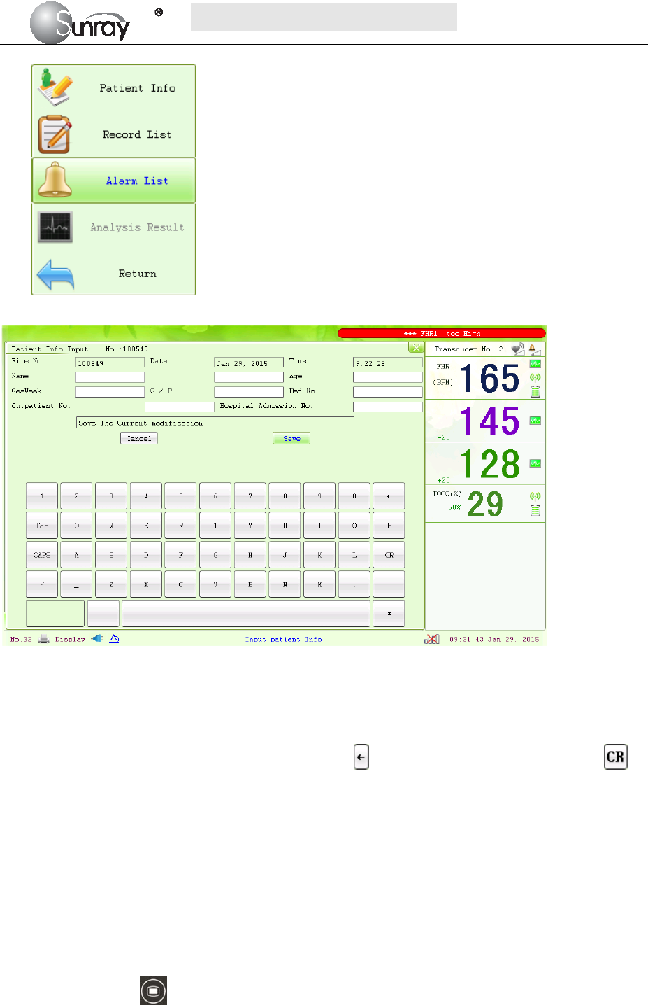
S
S
SR
R
RF
F
F6
6
61
1
18
8
8B
B
B6
6
6
U
U
Us
s
se
e
er
r
r’
’
’s
s
s
M
M
Ma
a
an
n
nu
u
ua
a
al
l
l
~41~
Fig. 8-3
Fig. 8-4
2) Use the soft keyboard and control knob to enter the patient File No., testing Date and Time, patient’s
Name, patient’s Age, Gestation Week, G/P information (G: number for gestation and labor), Bed No.,
Outpatient No., and Hospital Admission No. Select to delete the entered character; Select to
confirm this field information.
3) Select Save.
The monitoring does not stop when you change maternal information. After you select Save to exit, the new
ID takes the place of the old one for this patient.
8.10 Reviewing
Press the MENU key on the main interface, you may enter the setting interface. Rotate the control
knob until the cursor on the Load Files, and press the control knob, you may enter the files listed, shown as
Fig.8-5. Rotate the control knob until the cursor on the file you want and press the knob, and then you can
review the traces. If the PRINT key is pressed at this moment, the recorder will print the traces starting from
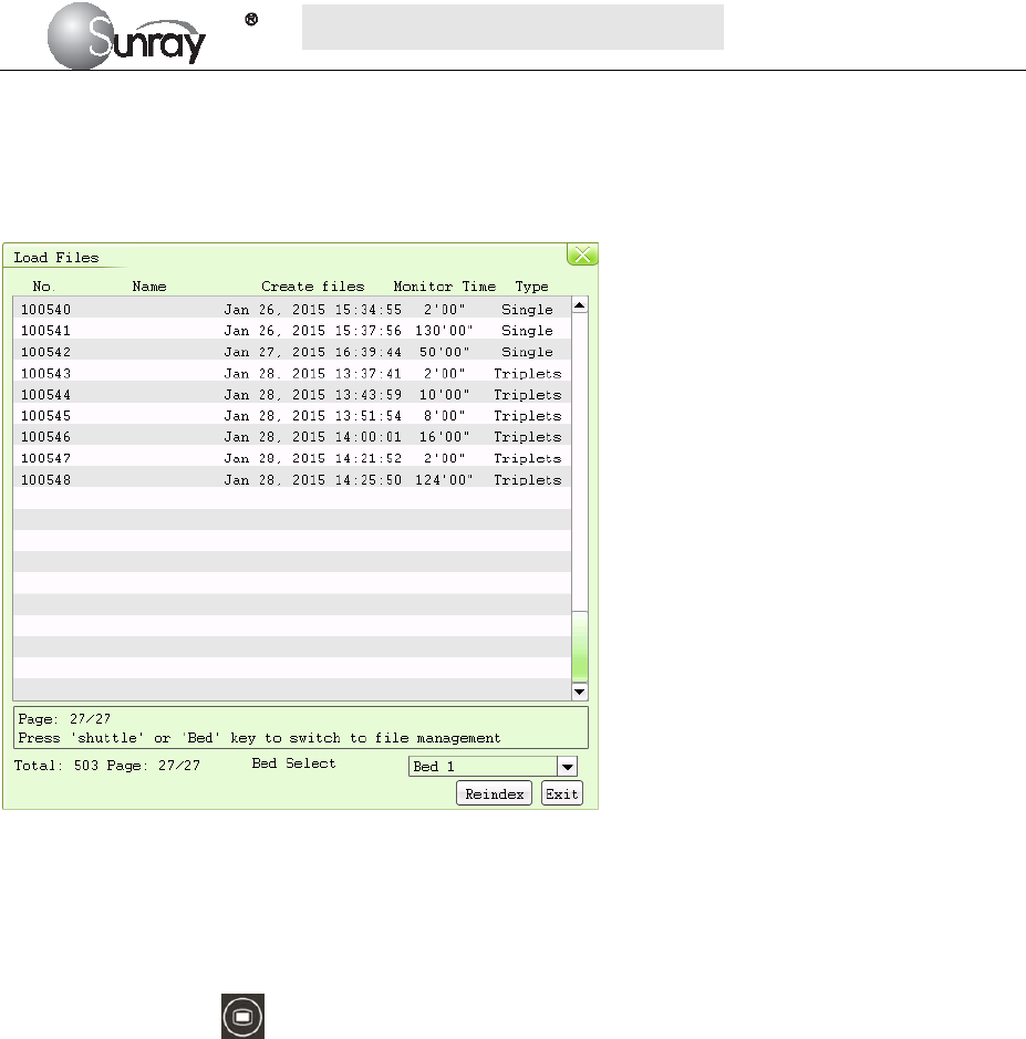
S
S
SR
R
RF
F
F6
6
61
1
18
8
8B
B
B6
6
6
U
U
Us
s
se
e
er
r
r’
’
’s
s
s
M
M
Ma
a
an
n
nu
u
ua
a
al
l
l
~42~
the left edge of the screen at a high speed.
Note:
If the monitor is monitoring, the function of Lode Files is invalid that you can’t review the previous traces.
Fig. 8-5
8.11 Delete Files
Press the MENU key on the main interface, you may enter the setting interface. Rotate the control
knob until the cursor on the Delete Files, and press the control knob, you may enter the files listed. Rotate
the control knob until the cursor on the file you want and press the knob, and the system will prompt that
“Confirm to delete file ID xxxxxx?” (see the Fig.8-6). Confirm it with “Yes”, or you may select “No” to
cancel the choice.
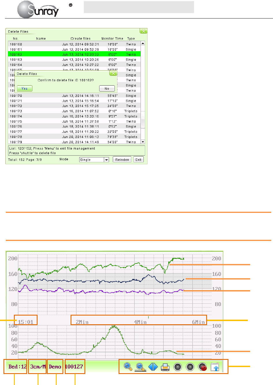
S
S
SR
R
RF
F
F6
6
61
1
18
8
8B
B
B6
6
6
U
U
Us
s
se
e
er
r
r’
’
’s
s
s
M
M
Ma
a
an
n
nu
u
ua
a
al
l
l
~43~
Fig.8-6
8.12 Fetal Monitoring Display
8.12.1 Traces
WARNING
Due to the LCD size, resolution and system settings, the traces displayed on the screen may look different
from the recorder printout. The printout should prevail when making diagnoses.
Fig. 8-7 Fetal Monitoring Traces
FHR3 Trace
FHR1 Trace
FHR2 Trace
TOCO Trace
Fetal monitoring
shortcut menus
1 2 3 4
1. Bed No.
2. FHR traces speed on the scree
3. The status of the monitoring
4. Patient’s file No.
5. The real time of the monitor
6. The relative time: the elapsed time for the current monitoring.
6 5

S
S
SR
R
RF
F
F6
6
61
1
18
8
8B
B
B6
6
6
U
U
Us
s
se
e
er
r
r’
’
’s
s
s
M
M
Ma
a
an
n
nu
u
ua
a
al
l
l
~44~
During monitoring or reviewing, the fetal monitoring trace window displays two types of traces: FHR trace,
and TOCO trace. The FHR 1, FHR 2 and FHR 3 traces in one patient’s (bed’s) fetal monitoring display
means triple FHRs, and FHR 1& FHR 2 traces in one patient’s (bed’s) fetal monitoring display means twin
FHRs
1) FHR Trace
The y-axis of the trace indicates the numerics of FHR. The range is 30 bpm ~ 240 bpm (American standard)
or 50 bpm ~ 210 bpm (International standard).
2) TOCO trace
The y-axis indicates the numeric of TOCO. The range is 0% ~ 100%.
3) Fetal monitoring shortcut menus
Besides, some other symbols appear among the traces:
Zoom in or out
Increase or decrease the FHR traces speed on the scree
Show the traces on the screen forth or back
Print
Turn on the Voice for FHR
Turn off the Voice for FHR
Tools menu, including the submenus of Patient information, Record List, Alarm list and Analysis
result
8.12.2 Data Saving
When the START key is pressed, the monitor saves data of the previous ID in a file, and then clears it from
the main interface. The main interface only displays the new patient’s data. During monitoring, the data is
saved every 10 minutes. All data of the same patient is saved in a file. The files are stored in the monitor.
When the data amount reaches the maximum capacity (800 files), the monitor deletes the oldest file(s)
automatically.
8.12.3 CTG Analysis
CTG analysis aims at a real-time trace, providing some reference data for the physicians. It only analyzes the
real-time trace after it’s been printed for 10 minutes, and the longest duration is 60 minutes.
WARNING:
1) CTG analysis is used for the surveillance of pregnancies and not in delivery room of childbirth.
2) CTG analysis is just an analysis intended to assist the physicians in interpreting the waveforms.
Conclusions should be drawn on the basis of the physicians’ diagnosis.
3) This analysis describes the fetal heart rate, the tocography and the fetal movements. It’s the
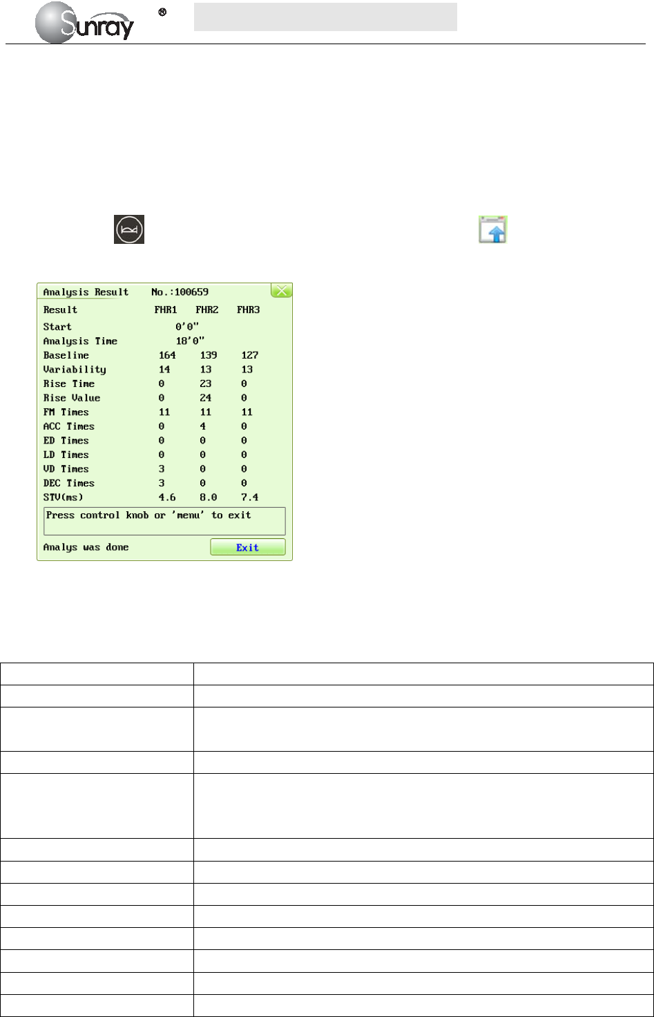
S
S
SR
R
RF
F
F6
6
61
1
18
8
8B
B
B6
6
6
U
U
Us
s
se
e
er
r
r’
’
’s
s
s
M
M
Ma
a
an
n
nu
u
ua
a
al
l
l
~45~
responsibility of qualified medical staff to do the diagnostic interpretation of the waveform.
1. CTG analyzing
NOTE:
1) CTG analysis can only start after the real-time trace has been printed for 10 minutes.
2) The CTG analysis result is for reference only. After the real-time trace is printed for 10 minutes, press
the Bed key and rotate the control knob to select the Tools menu key , press the control knob
and enter the shortcut menu, shown as Fig.8-3. Select the Analysis Result menu, shown as Fig.8-8.
Fig. 8-8 CTG analysis results
Refer to Fig. 8-8, the CTG analysis results on the screen include:
Start the relative start time of the analysis.
Analysis Time the analyzed monitoring time-period ,10 to 60 minutes.
Baseline Basal fetal heart rate, the average FHR in 10 minutes when it is not
influenced by fetal movement or contractions.
Variability the amplitude-variable of fetal heart rate (bpm)
Rise Time the acceleration time(s), including the acceleration with amplitude larger
than 10bpm and lasts more than 10 seconds, and the acceleration with
amplitude larger than 15bpm and lasts more than 15 seconds.
Rise Value the acceleration amplitude
FM Times the times of fetal movement
ACC Times the acceleration times
ED Times the times of early deceleration
LD Times the times of late deceleration
VD Times the times of variable deceleration
DEC Times the deceleration times
STV (ms) the short-term variation analysis result.
During 10 to 60-minute of the timer, the monitor gives CTG analysis results every minute.
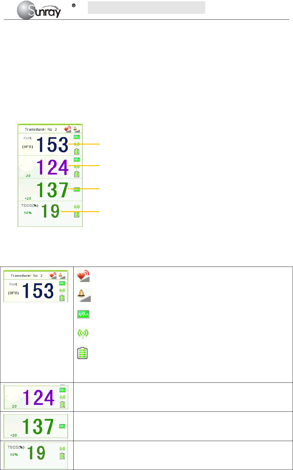
S
S
SR
R
RF
F
F6
6
61
1
18
8
8B
B
B6
6
6
U
U
Us
s
se
e
er
r
r’
’
’s
s
s
M
M
Ma
a
an
n
nu
u
ua
a
al
l
l
~46~
At the end of the printing, the recorder prints the CTG analysis results of this moment on the recorder paper.
Be aware that CTG analysis result is a calculation output. It can be used as a reference to assist medical
personnel in making correct diagnosis, instead of replacing it.
NOTE:
Do not disconnect the ultrasound transducer(s) before the printing stops, otherwise the analysis results will
not be printed.
8.12.4 Numerics
Fig. 8-9 Fetal Monitoring Numerics
The fetal monitoring values in the numeric window include FHR1 value, FHR2 value, FHR3 value and
TOCO value:
FH sound volume indicator
Audible alarm sound volume indicator
FHR signal quality. When the quality is poor, it turns into grey.
Wireless signal quality. When the quality is poor, it turns into grey
The battery charging indicator of wireless transducer.
Transducer No. 2: the No. of wireless transducers
153: FHR1 measurement numeric.
124: FHR2 measurement numeric.
137: FHR3 measurement numeric.
19: current UA measurement numeric.
50%: TOCO gain value
FHR1
FHR2
FHR3
TOCO

S
S
SR
R
RF
F
F6
6
61
1
18
8
8B
B
B6
6
6
U
U
Us
s
se
e
er
r
r’
’
’s
s
s
M
M
Ma
a
an
n
nu
u
ua
a
al
l
l
~47~
Chapter 9 After Monitoring
9.1 Completing Monitoring
After monitoring,
1) Remove transducers or electrodes from the patient; wipe the remaining gel off the patient and the
transducer with a clean soft cloth or tissue.
2) Long press the PRINT key to stop printing.
3) Wait the paper to stop and then tear it off along the perforation.
NOTE:
After the fetus is delivered in the labor, the monitor may pick up signals of the umbilical cord and display a
trace/numeric. To avoid misinterpretation, it is recommended to remove the transducers from the patient and
switch off the monitor immediately after the fetus is delivered.
9.2 Switching Off
1) Press and hold the POWER key for at least 3 seconds to switch off the monitor.
2) Unplug the power cord.
CAUTION:
Do not press the POWER key continuously. Allow at least 10 seconds between switching the monitor
on and off.

S
S
SR
R
RF
F
F6
6
61
1
18
8
8B
B
B6
6
6
U
U
Us
s
se
e
er
r
r’
’
’s
s
s
M
M
Ma
a
an
n
nu
u
ua
a
al
l
l
~48~
Chapter 10 Maintenance and Cleaning
10.1 Maintenance
10.1.1 Maintaining Inspection
1) Visual Inspection
Prior to using the monitor every time, do the following inspections:
Check the monitor and accessories to see if there is any visible evidence of damage that may affect
patient safety. Pay special attention to the cracks on the transducers and cables before immersing
them into conductive fluid.
Check all the outer cables, power socket and power cables.
Check if the monitor functions properly.
If any damage is detected, stop using the monitor on the patient. Replace the damage part(s) or
contact the manufacturer for service before reusing it.
2) Routine Inspection
The overall check of the monitor, including safety check and function check, should be performed by
qualified personnel every 6 to 12 months, and each time after service.
The equipment should undergo periodic safety testing to ensure proper patient isolation from leakage
currents. This should include leakage current measurement and insulation testing. The recommended testing
interval is once a year or as specified in the institution’s test and inspection protocol.
3) Mechanical Inspection
Make sure all exposed screws are tight.
Check the external cables for splits, cracks or signs of twisting.
Replace any cable that shows serious damage.
Pay particular attention to the supply socket.
WARNING:
Failure on the part of the responsible individual hospital or institution employing the use of this equipment to
implement a satisfactory maintenance schedule may cause undue equipment failure and possible health
hazards.
CAUTION:
Besides the maintenance requirements recommended in this manual, comply with local regulations on
maintenance and measurement.
10.1.2 Maintenance of Monitor
Keep the exterior surface of the monitor clean, and free of dust, dirt and residual liquids. Clean with a damp
cloth using mild soap and water or hospital approved non-abrasive disinfectants.
The gathering of dew on the screen may occur with abrupt temperature or humidity changes. A table
environment is recommended. Stop using the monitor and contact the service personnel immediately if
accidental wetting occurs.

S
S
SR
R
RF
F
F6
6
61
1
18
8
8B
B
B6
6
6
U
U
Us
s
se
e
er
r
r’
’
’s
s
s
M
M
Ma
a
an
n
nu
u
ua
a
al
l
l
~49~
Scratching and damaging the screen should be avoided.
10.1.3 Maintenance of Transducers
Keep the transducers in a dry environment, where the temperature had better be lower than +45°C (+115 ºF).
Gel must be wiped from the US transducer after use. These precautions will prolong the life of the
transducer.
Although transducers are designed for durability, they should be handled with care. Rough handling could
damage the cover, piezoelectric crystals and mechanical movement. Contacting the transducers with hard or
sharp objects should be avoided. Do not excessively flex the cables.
10.1.4 Storage of Recorder Paper
When storing recorder paper (including used paper with traces):
Do not store in plastic envelopes.
Do not leave exposed to direct sunlight or ultraviolet light.
Do not exceed a storage temperature of +40 ºC (+104 ºF).
Do not exceed a relative humidity of 90%.
Storage conditions outside these limits may distort the paper and adversely affect the accuracy of grid lines or
make the trace unreadable.
10.1.5 Maintaining the Battery
It is required to follow the instructions in this user manual during installation, storage and maintenance of the
battery.
When the battery is charged, used or stored, keep it away from objects or materials with static electric
charges.
The recommended charge temperature range is from 0 ºC (+32 ºF) to +40 ºC (+104 ºF). Do not exceed this
range.
When not using battery for an extended period, remove it from the monitor and store it in a place with low
humidity and low temperature.
Batteries have life cycles. If the time that the monitor uses the battery becomes much shorter than usual, the
battery life is at an end. Replace it with a new one the same as the one provided or recommended by the
manufacturer.
10.2 Cleaning and Disinfecting of Transducers
Before starting cleaning or disinfection, carefully review the technical information and follow all the
precautions for use, safety, storage and disposal of the cleaning and disinfecting agents as listed by their
manufacturers.
For devices intended for use on immune-compromised patients, use a sterile towel for cleaning the device
during the cleaning and disinfection process.
Do not:
1) Immerse a transducer in water.
2) Handle transducers roughly. This could damage the cover, piezoelectric crystals and mechanical
movement. Transducer covers are made of soft plastic; avoid contact with hard or sharp objects.
3) Flex the cables excessively.

S
S
SR
R
RF
F
F6
6
61
1
18
8
8B
B
B6
6
6
U
U
Us
s
se
e
er
r
r’
’
’s
s
s
M
M
Ma
a
an
n
nu
u
ua
a
al
l
l
~50~
4) Allow cleaning solutions or transducers to exceed a temperature of 45°C (113°F).
5) Autoclave the transducers and cables or heat them above 70°C (158 °F).
Caution:
Do not immerse the transducers during any stage of the cleaning/disinfection process.
The following cleaning and low level disinfection procedure is recommended.
Do not mix disinfecting solutions as hazardous gases may result.
The cleaning procedure will be more effective in reducing contamination if cleaning is done prior to
drying of adherent visible soil (for example, organic matter or other debris) on the transducer.
Do not reuse alcohol for disinfection.
10.2.1 Cleaning and Disinfecting
Cleaning
1) Wipe the transducer using a damp towel and then a towel with a recommended detergent
such as an enzymatic detergent. Prepare the detergent as recommended by its manufacturer.
2) Wipe the device with a damp towel for at least 3 times to remove detergent.
3) Visually inspect the transducer. If adherent soil is still present, repeat steps 1 and 2.
4) Dry the transducer thoroughly with a clean, soft towel.
Disinfecting
The transducers should be cleaned prior to disinfecting.
Using 70% Isopropanol
1) Wipe the transducer with clean towel soaking in 70% Isopropanol completely for a
minimum of five (5) minutes, but not more than ten (10) minutes recommendations.
2) Wipe the transducer with a damp towel carefully for at least 3 times to remove residual
Isopropanol.
3) Dry the transducer thoroughly with a clean soft towel.
4) Follow your facility's post-processing handling procedures to eliminate or minimize
recontamination of the device before reuse. Contact your facility's Infection Control Office
or Epidemiologist for information regarding such procedures.
10.3 Cleaning and Disinfecting of Reusable Belts
Refer to the manufacturer’s instruction.

S
S
SR
R
RF
F
F6
6
61
1
18
8
8B
B
B6
6
6
U
U
Us
s
se
e
er
r
r’
’
’s
s
s
M
M
Ma
a
an
n
nu
u
ua
a
al
l
l
~51~
10.4 Cleaning of Recorder
The recorder platen, thermal print head and paper sensing mechanism must be cleaned at least once a year or
when needed (when traces become faint).
To do this:
Clean the recorder platen with a lint-free cloth dampened in soap/ water solution.
Wipe the thermal array using a cotton swab moistened with 70% Isopropyl alcohol-based solution.
Check that the paper sensing mechanism is free of dust.
WARNING:
Switch off the monitor and remove the power cord prior to recorder cleaning.
10.5 Sterilizing
Do not sterilize the monitor or the accessories, unless this is necessary according to your hospital regulation.
10.6 Disposing of the Monitor
WARNING:
To avoid contaminating or infecting personnel, the service environment or other equipment, make sure the
equipment has been appropriately disinfected and decontaminated before disposal at the end of its useful life,
in accordance with your country’s laws for equipment containing electrical and electronic parts.
Do not dispose of waste electrical and electronic equipment as unsorted municipal waste.
Collect it separately, so that it can be safely and properly reused, treated, recycled, or recovered.

S
S
SR
R
RF
F
F6
6
61
1
18
8
8B
B
B6
6
6
U
U
Us
s
se
e
er
r
r’
’
’s
s
s
M
M
Ma
a
an
n
nu
u
ua
a
al
l
l
~52~
Chapter 11 Product Specifications
11.1 Safety Classifications
Item Specification
Anti-electroshock type Class I equipment with internal power supply
Anti-electroshock degree US/TOCO/FM : Type B
Explosion proof level Ordinary equipment, without explosion proof
Degree of Protection against
Harmful Ingress of Water
Main Unit: IPX0
US/TOCO Transducers: IPX8
Other Accessories: No liquid ingress protection
EMC Group I Class A
Working system Continuous running equipment
Equipment type Portable
11.2 Environmental Specifications
Working Temperature: +5℃~+ 40℃( +41 ºF ~ +104 ºF)
Relative Humidity: ≤80% (non-condensing)
Atmospheric Pressure: 86.0kPa~106.0kPa
Transport and
Storage
Temperature: -20℃~+ 55℃(-4ºF ~ +131 ºF)
Relative Humidity: ≤80% (non-condensing)
Atmospheric Pressure: 86.0kPa~106.0kPa
11.3 Physical Specifications
Monitor
Dimensions and Weight Size (depth x width x height): 358mm×360mm×114mm
Weight: 5.0 kg
Power Supply Operating Voltage: 100-240V
Operating Frequency: 50/60Hz
Input Power : 100VA
Battery: 4000mAh
Display
LCD Size: 10.2 inch
Resolution: 1024*600
Signal Interface
RS232 interface (DB9 or D-Sub), RJ45 interface

S
S
SR
R
RF
F
F6
6
61
1
18
8
8B
B
B6
6
6
U
U
Us
s
se
e
er
r
r’
’
’s
s
s
M
M
Ma
a
an
n
nu
u
ua
a
al
l
l
~53~
11.4 Performance Specifications
Fetal monitoring (FHR, TOCO, FM)
Ultrasound
Technique: ultrasonic pulse Doppler
Ultrasonic operating frequency: 0.8MHz~5.0MHz
US frequency: 2MHz
Spatial-average pulse-average intensity (ISAPA): <20mW/cm2
Offset with nominal frequency: ≤±10%
Mechanical index MI: < 1
Thermal index for soft tissue TIS: < 1
Thermal index for bone TIB: <1
FHR measuring range: 30 ~240 bpm/min
FHR measurement accuracy: ±2 bpm/min
FHR display scope: 30~240 bpm /min
Uterine contraction
p
ressure (TOCO)
Coverage scope of uterine contraction pressure: 0~100 units
Nonlinear error for uterine contraction pressure measurement: ±10%
Paper feeding error for curve recording: <±5%
Fetal movement (FM) Manual
11.5 Recorder Specifications
Printing
specifications
Printing method Thermal sensitive line dot method
Effective printing width 144 mm
Printing speed:
Standard Speed (Real-Time Traces ): 1 cm/min, 2 cm/min, 3 cm/min
Fast Print Speed (Stored Traces): Up to 75mm/sec
Paper width 156mm
Paper feed method 1 dot line / 4 pulse, bipolar 1-2 phase
excitation
Paper feed accuracy 5% at fixed-speed feed with the back
tension of approx.100g(0.98N)
Record Information:
FHR1 trace/mark, FHR2 trace/mark,
FHR3 trace/mark, TOCO trace, fetal
movement mark, date, time, printing
speed, ID, name, FHR2 Offset, FHR3
Offset etc.
Detection
function
Head temperature detection Thermistor
Paper detection Photo interrupter
Mark detection

S
S
SR
R
RF
F
F6
6
61
1
18
8
8B
B
B6
6
6
U
U
Us
s
se
e
er
r
r’
’
’s
s
s
M
M
Ma
a
an
n
nu
u
ua
a
al
l
l
~54~
11.6 Rechargeable Lithium-ion Battery of the equipment
Type: Rechargeable Lithium-ion Battery
Continual Working Time: 2 hours ~ 4 hours (depending on the configuration)
Necessary Charge Time: 4 hours ~ 5 hours
Nominal Capacity: 4000mAh
Nominal Voltage: 11.1V
Charge Mode: Constant current/ constant voltage(CC-CV)
Charge Current (Standard): 0.2C(780mA)
Charge Voltage (Standard): (12 ± 0.1) V
Maximum Continuous Charge
Current: 2000mA
11.7 Rechargeable Li-Polymer Battery of the wireless
transducer
Type: Rechargeable Li-Polymer Battery
Continual Working Time: 4 hours ~ 8 hours (depending on the configuration)
Necessary Charge Time: 4 hours ~ 5 hours
Nominal Capacity: 1150mAh
Nominal Voltage: 3.7V
Charge Mode: Constant current/ constant voltage
Charge Current (Standard): 0.2C (230mA)
Charge Voltage (Standard): (5 ± 0.1) V
Maximum Continuous Charge
Current: 1150mA
S
S
SR
R
RF
F
F6
6
61
1
18
8
8B
B
B6
6
6
U
U
Us
s
se
e
er
r
r’
’
’s
s
s
M
M
Ma
a
an
n
nu
u
ua
a
al
l
l
~55~
Chapter 12 Abbreviation
The abbreviations used in this manual and their full names are listed below:
Abbreviation Full Name
AC Alternative Current
CTG Cardiotocography
US Ultrasound (Transducer)
FHR Fetal Heat Rate
TOCO Tocotonometer
UA Uterine Activity (TOCO)
FM Fetal Movement
NST Non Stress Test
MRI Magnetic Resonance Imaging
LCD Liquid Crystal Display
ID Identity

S
S
SR
R
RF
F
F6
6
61
1
18
8
8B
B
B6
6
6
U
U
Us
s
se
e
er
r
r’
’
’s
s
s
M
M
Ma
a
an
n
nu
u
ua
a
al
l
l
~56~
Chapter 13 EMC Information
The device and its accessories, listed in the accessories section, comply with the following EMC standards:
• EN/IEC 60601-1-2: 2001+A1:2004
Take special precautions regarding electromagnetic compatibility (EMC) when using medical electrical
equipment. You must operate your monitoring equipment according to the EMC information provided in this
book. Before using the device, assess the electromagnetic compatibility of the device with surrounding
equipment.
CAUTION Although this is an electrical Class II device, it has a protective earth conductor which is needed
for EMC purposes.
Always use the supplied power cord with the three-prong plug to connect the monitor to AC mains.
Never adapt the three-prong plug from the power supply to fit a two-slot outlet.
CAUTION The use of accessories, transducers and cables other than those specified may result in increased
electromagnetic emissions or decreased electromagnetic immunity of the device.
WARNING Do NOT use cordless/mobile phones or any other portable RF communication system within the
patient vicinity, or within a 1.0 m radius of any part of the fetal monitoring system.
EMC Testing
CAUTION Fetal parameters, especially ultrasound, are sensitive measurements involving small signals, and
the monitoring equipment contains very sensitive high gain front-end amplifiers. Immunity levels for
radiated RF electromagnetic fields and conducted disturbances induced by RF fields are subject to
technological limitations. To ensure that external electromagnetic fields do not cause erroneous
measurements, it is recommended to avoid the use of electrically radiating equipment in close proximity to
these measurements.
Reducing Electromagnetic Interference
CAUTION The device should not be used adjacent to, or stacked with, other equipment unless otherwise
specified.
The product and associated accessories can be susceptible to interference from continuous, repetitive, power
line bursts, and other RF energy sources, even if the other equipment is compliant with EN 60601-1-2
emission requirements. Examples of other sources of RF interference are other medical electrical devices,
cellular products, information technology equipment, and radio/television transmissions.
When electromagnetic interference (EMI) is encountered, for example, if you can hear spurious noises on the
fetal monitor’s loudspeaker, attempt to locate the source. Assess the following:
Is the interference due to misplaced or poorly applied transducers? If so, re-apply transducers correctly
according to directions in this book or in the Instructions for Use accompanying the accessory.
Is the interference intermittent or constant?
Does the interference occur only in certain locations?
Does the interference occur only when in close proximity to certain medical electrical equipment?
Once the source is located, there are a number of things that can be done to mitigate the problem:
Eliminating the source. Turn off or move possible sources of EMI to reduce their strength.
Attenuating the coupling. If the coupling path is through the patient leads, the interference may be
reduced by moving and/or rearranging the leads. If the coupling is through the power cord, connecting
the system to a different circuit may help.

S
S
SR
R
RF
F
F6
6
61
1
18
8
8B
B
B6
6
6
U
U
Us
s
se
e
er
r
r’
’
’s
s
s
M
M
Ma
a
an
n
nu
u
ua
a
al
l
l
~57~
Adding external attenuators. If EMI becomes an unusually difficult problem, external devices such as an
isolation transformer or a transient suppressor may be of help. Your Service Provider can be of help in
determining the need for external devices.
Where it has been established that electromagnetic interference is affecting physiological parameter
measurement values, a physician, or a suitably qualified person authorized by a physician, should determine
if it will negatively impact patient diagnosis or treatment.
Electromagnetic Emissions and Immunity
The monitor is suitable for use in the electromagnetic environment specified in the table below. You must
ensure that it is used in such an environment.
Table 1 - Guidance and Manufacturer’s Declaration: Electromagnetic Emissions
The SRF618B6 is intended for use in the electromagnetic environment specified below. The customer or the user
of the SRF618B6 should assure that it is used in such an environment.
Emissions Compliance Electromagnetic environment-- guidance
RF emissions
CISPR 11
Group 1
The SRF618B6 uses RF energy only for its internal function.
Therefore, its RF emissions are very low and are not likely to
cause any interference in nearby electronic equipment.
RF emissions
CISPR 11
Class A
The SRF618B6 is suitable for use in all establishments, but if
used in domestic establishments and those directly connected
to the public low-voltage power supply network that supplies
buildings used for domestic purposes, whatever additional
measures are necessary.
Harmonic emissions
IEC 61000-3-2
Not applicable
Voltage fluctuations/
flicker emissions
IEC 61000-3-3
Complies
Electromagnetic Immunity
The monitor is suitable for use in the specified electromagnetic environment. The user must ensure that it is
used in the appropriate environment as described below.
Table 2-Guidance and manufacture’s declaration – electromagnetic immunity
The SRF618B6 is intended for use in the electromagnetic environment specified below. The customer or the user of
the SRF618B6 should assure that it is used in such an environment.
Immunity test
IEC 60601
test level
Compliance level
Electromagnetic environment
--guidance
Electrostatic
discharge (ESD)
IEC 61000-4-2
±6 kV contact
±8 kV air
±6 kV contact
±8 kV air
Floors should be wood, concrete or
ceramic tile. If floors are covered with
synthetic material, the relative
humidity should be at least 30 %.
Electrical fast
transient/burst
IEC 61000-4-4
±2 kV for power
supply lines
±2 kV for power
supply lines
Mains power quality should be that of
a typical commercial or hospital
environment.
Surge
IEC 61000-4-5
±1 kV line(s) to line(s)
± 2 kV line(s) to earth
±1 kV line(s) to line(s)
± 2 kV line(s) to earth
Mains power quality should be that of
a typical commercial or hospital

S
S
SR
R
RF
F
F6
6
61
1
18
8
8B
B
B6
6
6
U
U
Us
s
se
e
er
r
r’
’
’s
s
s
M
M
Ma
a
an
n
nu
u
ua
a
al
l
l
~58~
environment.
Voltage dips, short
interruptions and
voltage variations
on power supply
input lines
IEC 61000-4-11
<5 % UT
(>95 % dip in UT)
for 0,5 cycle
40 % UT
(60 % dip in UT)
for 5 cycles
70 % UT
(30 % dip in UT)
for 25 cycles
<5 % UT
(>95 % dip in UT)
for 5s
<5 % UT
(>95 % dip in UT)
for 0,5 cycle
40 % UT
(60 % dip in UT)
for 5 cycles
70 % UT
(30 % dip in UT)
for 25 cycles)
<5 % UT
(>95 % dip in UT)
for 5s
Mains power quality should be that of
a typical commercial or hospital
environment. If a dips or an
interruption of mains power occurs,
the current of the SRF618B6 may be
dropped off from normal level, it may
be necessary to use uninterruptible
power supply or a battery.
Power frequency
(50/60 Hz)
magnetic field
IEC 61000-4-8
3 A/m
3A/m Power frequency magnetic fields
should be at levels characteristic of
a typical location in a typical
commercial or hospital
environment.
NOTE UT is the a.c. mains voltage prior to application of the test level
Table 3. Guidance and manufacturer’s declaration – electromagnetic immunity
The SRF618B6 is intended for use in the electromagnetic environment specified below. The customer or the
user of the SRF618B6 should assure that it is used in such an environment.
Immunity test
IEC 60601
test level
Compliance
level
Electromagnetic environment – guidance
Conducted RF
IEC 61000-4-6
Radiated RF
IEC 61000-4-3
3 Vrms
150 kHz to
80 MHz
3 V/m
80 MHz to
2.5 GHz
3 Vrms
3 V/m
Portable and mobile RF communications equipment
should be used no closer to any part of the SRF618B6,
including cables, than the recommended separation
distance calculated from the equation applicable to the
frequency of the transmitter.
Recommended separation distance
where P is the maximum output power rating of the
transmitter in watts (W) according to the transmitter
manufacturer and d is the recommended separation
Distance in metres (m).
Field strengths from fixed RF transmitters, as
determined by an electromagnetic site survey,a should
be less than the compliance level in each frequency
range.b
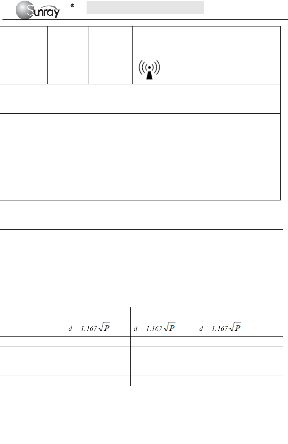
S
S
SR
R
RF
F
F6
6
61
1
18
8
8B
B
B6
6
6
U
U
Us
s
se
e
er
r
r’
’
’s
s
s
M
M
Ma
a
an
n
nu
u
ua
a
al
l
l
~59~
Interference may occur in the vicinity of equipment
marked with the following symbol:
NOTE 1 At 80 MHz and 800 MHz, the higher frequency range applies.
NOTE 2 These guidelines may not apply in all situations. Electromagnetic propagation is affected by
absorption and reflection from structures, objects and people.
a. Field strengths from fixed transmitters, such as base stations for radio (cellular/cordless) telephones and land
mobile radios, amateur radio, AM and FM radio broadcast and TV broadcast cannot be predicted theoretically
with accuracy. To assess the electromagnetic environment due to fixed RF transmitters, an electromagnetic
site survey should be considered. If the measured field strength in the location in which the SRF618B6 is used
exceeds the applicable RF compliance level above, the SRF618B6 should be observed to verify normal
operation. If abnormal performance is observed, additional measures may be necessary, such as re-orienting or
relocating the SRF618B6.
b. Over the frequency range 150 kHz to 80 MHz, field strengths should be less than 3 V/m.
Table 4. Recommended separation distances between portable and mobile RF communications
equipment and the SRF618B6
The SRF618B6 is intended for use in an electromagnetic environment in which radiated RF disturbances are
controlled. The customer or the user of the SRF618B6 can help prevent electromagnetic interference by
maintaining a minimum distance between portable and mobile RF communications equipment (transmitters)
and the SRF618B6 as recommended below, according to the maximum output power of the communications
equipment.
Rated maximum
output power
of transmitter
W
Separation distance according to frequency of transmitter
m
150 kHz to 80 MHz
80 MHz to 800 MHz
800 MHz to 2.5 GHz
0.01 0.117 0.117 0.233
0.1 0.369 0.369 0.738
1 1.167 1.167 2.333
10 3.690 3.690 7.377
100 11.67 11.67 23.33
For transmitters rated at a maximum output power not listed above, the recommended separation distance d in
metres (m) can be estimated using the equation applicable to the frequency of the transmitter, where P is the
maximum output power rating of the transmitter in watts (W) according to the transmitter manufacturer.
NOTE 1 At 80 MHz and 800 MHz, the separation distance for the higher frequency range applies.
NOTE 2 These guidelines may not apply in all situations. Electromagnetic propagation is affected by
absorption and reflection from structures, objects and people.

S
S
SR
R
RF
F
F6
6
61
1
18
8
8B
B
B6
6
6
U
U
Us
s
se
e
er
r
r’
’
’s
s
s
M
M
Ma
a
an
n
nu
u
ua
a
al
l
l
~60~
Chapter 14 FCC Statement
Caution: The user is cautioned that changes or modifications not expressly approved by the party responsible
for compliance could void the user's authority to operate the equipment.
This device complies with Part 15 of the FCC Rules. Operation is subject to the following two conditions: (1)
this device may not cause harmful interference, and (2) this device must accept any interference received,
including interference that may cause undesired operation.
NOTE: This equipment has been tested and found to comply with the limits for a Class B digital device,
pursuant to Part 15 of the FCC Rules. These limits are designed to provide reasonable protection against
harmful interference in a residential installation. This equipment generates, uses and can radiate radio
frequency energy and, if not installed and used in accordance with the instructions, may cause harmful
interference to radio communications. However, there is no guarantee that interference will not occur in a
particular installation.
If this equipment does cause harmful interference to radio or television reception, which can be determined
by turning the equipment off and on, the user is encouraged to try to correct the interference by one or more
of the following measures:
-- Reorient or relocate the receiving antenna.
-- Increase the separation between the equipment and receiver.
-- Connect the equipment into an outlet on a circuit different from that to which the receiver is connected.
-- Consult the dealer or an experienced radio/TV technician for help.
This equipment complies with FCC radiation exposure limits set forth for an uncontrolled environment.
This transmitter must not be co-located or operating in conjunction with any other antenna or transmitter.
Chapter 15 Ultrasonic Related Information
Ultrasonic Principle
ALARA
Please observe ALARA (As Low As Reasonably Achievable) principle when using ultrasound. So far there is
no confirmed evidence to prove that ultrasound has obvious harm to human, but the users shall be cautious
when using ultrasound. Provided that sufficient diagnostic information is acquired, try to shorten the time to
examine the patient with the Transducer on one body position. The ultrasound power and acoustic intensity
are relevant to scanning time. The user shall observe ALARA principle to select an appropriate ultrasound
power for the exam-based on his exam needs.
Ultrasound Effects
Ultrasound effect shall include heating and cavitation.
Heating effect: Ultrasound in nature is mechanical wave. During its propagation in human body, the human
tissues are oscillated, heat is generated, and human tissue temperatures. Be vigilant to damage due to the
heating effect, and always follow ALARA principle.
Cavitation: Cavitation can occur when sound passes through an area that contains small bubbles. With

S
S
SR
R
RF
F
F6
6
61
1
18
8
8B
B
B6
6
6
U
U
Us
s
se
e
er
r
r’
’
’s
s
s
M
M
Ma
a
an
n
nu
u
ua
a
al
l
l
~61~
ultrasound impact on these small bubbles, temperature and pressure around the space of the bubbles will
increase, or even oscillate and explode, which may result in physical or chemical effects on the surrounding
tissues.
Relevant Parameters
The main parameters related to acoustic power are: transmit frequency, transmit focus number, transmit
voltage, transmit angle, element pitch, etc. These parameters vary subject to exam modes. Follow ALARA
principle to select the appropriate power for scanning.
A multiplicative factor applied to acoustic output parameters intended to account for ultrasonic attenuation of
tissue between the source and a particular location in the tissue. In the calculation of all mechanical, the
average ultrasonic attenuation is assumed to be 0.3dB/cm-MHz along the beam axis in the body.
References
(1) AIUM: ”Acoustic Output Measurement Standard For Diagnostic Ultrasound Equipment,” Revision 3,
NEMA Standard Publication UD 2-2004, National Electrical Manufacturers Association,2004
(2) AIUM/NEMA: “Standard for real-time display of thermal and mechanical acoustic output indices on
diagnostic ultrasound equipment,” Revision 2, NEMA Standard Publication UD 3-2004, National
Electrical Manufacturers Association,2004
(3) Measurement and characterization of ultrasonic fields using hydrophones in the frequency range
0.5MHz to 15MHz
(4) Ultrasonic Power measurement in liquids in the frequency range 0.5MHz to 25MHz
(5) 5.FDA:”510(K) Guide for Measuring and Reporting the Acoustic Output Diagnostic Ultrasound
Medical Devices,” Center for Devices and Radiological Health, Food and Drug Administration
Statistics
Statistical Analysis of Measurement Data
A statistical analysis was performed on the base of a tolerance limit approach. The mean and standard deviation of
the Spatial-Peak, Temporal-Average Intensityand the Spatial-Peak, Pulse-Average Intensity were found, and the
upper output limits were calculated from the following formula : X= +KS
Where X is the upper output parameter limit, is the average of the measured output parameter, S is the
standard deviation of the measured output parameter, and K is a factor from Reference [M.G. Natrella,
Experimental Statistics NBS Handbook 91, 1966 Table A-7]. When sample size is 3 and P=γ=90%, the K value
was 4.258. A value of K was chosen which corresponds to a 90% probability that 90% of all probes would fall
below the calculated limits X. The following table presents the calculated values using the 4.258 value for K.
Table 2 Results for SRF618B6 Transducers
Transducers Wired FHR Transducer Wireless FHR Transducer
Sample Size 3 3
Mode PW PW
ISATA
(mW/cm²)
Mean ( ) 0.802 0.811
Std Dev (S) 0.050 0.084
Limit (X) 1.019 1.172
ISAPA
(mW/cm²)
Mean ( ) 11.02 11.13
Std Dev (S) 0.699 1.157
Limit (X) 13.99 16.06

S
S
SR
R
RF
F
F6
6
61
1
18
8
8B
B
B6
6
6
U
U
Us
s
se
e
er
r
r’
’
’s
s
s
M
M
Ma
a
an
n
nu
u
ua
a
al
l
l
~62~
Results
Track 1 Reporting Table show the worst-case indices for each Transducer tested.
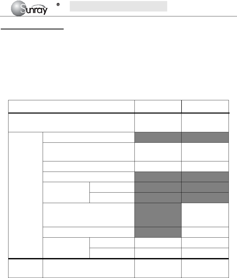
S
S
SR
R
RF
F
F6
6
61
1
18
8
8B
B
B6
6
6
U
U
Us
s
se
e
er
r
r’
’
’s
s
s
M
M
Ma
a
an
n
nu
u
ua
a
al
l
l
~63~
Acoustic Output Report
ACOUSTIC OUTPUT REPORTING TABLE TRACK 1
Non-Auto-scanning Mode
System Model: Fetal Monitor, Model: SRF618B6
Transducer: Wired FHR Transducer (3 samples for this type of transducer)
Operating Mode: PW-Mode
Application(s): Fetal
Acoustic Output ISATA
(mW/cm²) ISAPA
(mW/cm²)
Global Maximum Value
0.75
0.80
0.85
10.30
11.05
11.70
Associated
Acoustic
Parameter
pr.3 (MPa)
Wo (mW)
0.59
0.63
0.67
0.59
0.63
0.67
fc (MHz) 2.00 2.00
zsp (cm)
Beam dimensions
x-6 (cm)
Y-6 (cm)
PD (µs)
21.90
21.80
21.90
PRF (Hz) 3330
EBD
Az. (cm) Φ1.0 Φ1.0
Ele. (cm) Φ1.0 Φ1.0
Operating
Control
Conditions
Control 1:Default Settings √ √
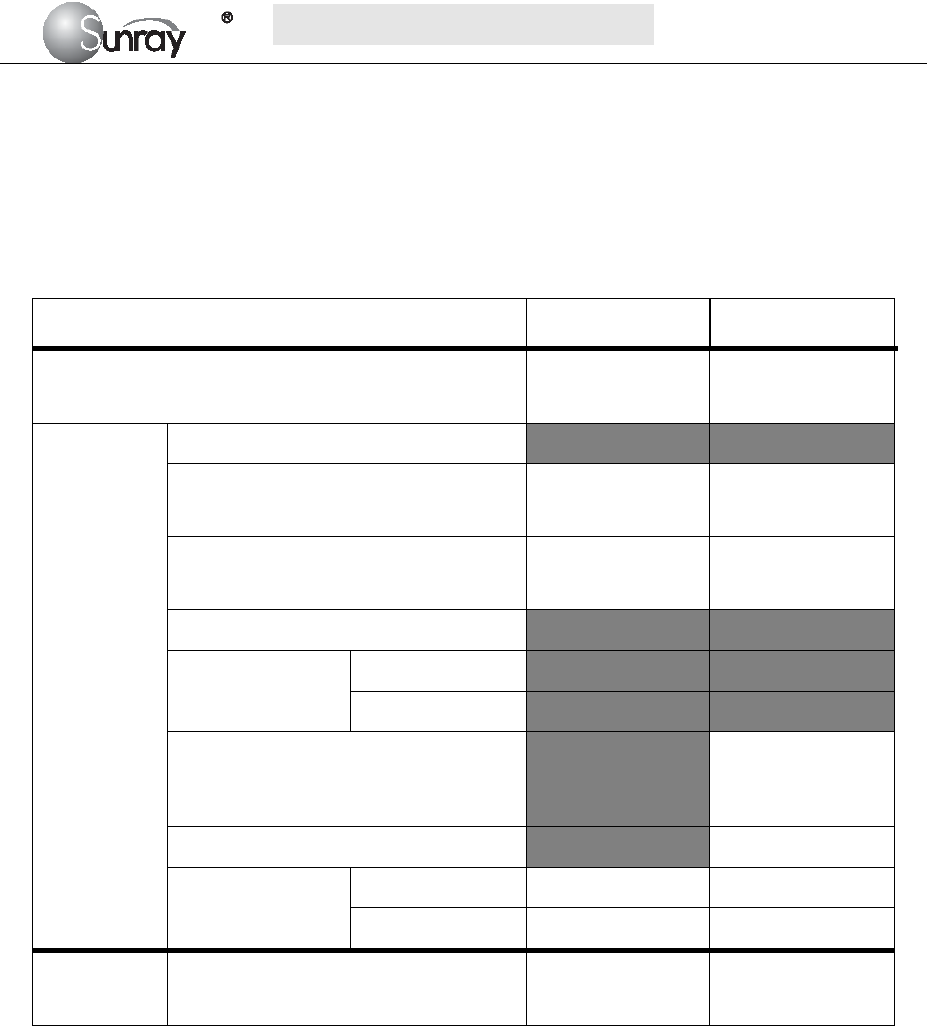
S
S
SR
R
RF
F
F6
6
61
1
18
8
8B
B
B6
6
6
U
U
Us
s
se
e
er
r
r’
’
’s
s
s
M
M
Ma
a
an
n
nu
u
ua
a
al
l
l
~64~
ACOUSTIC OUTPUT REPORTING TABLE TRACK 1
Non-Auto-scanning Mode
System Model: Fetal Monitor, Model: SRF618B6
Transducer: Wireless FHR Transducer (3 samples for this type of transducer)
Operating Mode: PW-Mode
Application(s): Fetal
Acoustic Output ISATA
(mW/cm²) ISAPA
(mW/cm²)
Global Maximum Value
0.73
0.78
0.90
10.13
10.87
12.40
Associated
Acoustic
Parameter
pr.3 (MPa)
Wo (mW)
0.58
0.62
0.71
0.58
0.62
0.71
fc (MHz)
1.99
2.00
2.00
1.99
2.00
2.00
zsp (cm)
Beam dimensions
x-6 (cm)
Y-6 (cm)
PD (µs)
21.90
21.80
21.90
PRF (Hz) 3330
EBD
Az. (cm) Φ1.0 Φ1.0
Ele. (cm) Φ1.0 Φ1.0
Operating
Control
Conditions
Control 1:Default Settings √ √

S
S
SR
R
RF
F
F6
6
61
1
18
8
8B
B
B6
6
6
U
U
Us
s
se
e
er
r
r’
’
’s
s
s
M
M
Ma
a
an
n
nu
u
ua
a
al
l
l
~65~
Uncertainties
The uncertainties in the measurements were predominantly systematic in origin; the random uncertainties were
negligible in comparison. The overall systematic uncertainties were determined as follows:
1) Hydrophone calibration
The uncertainty in the calibration of the hydrophone including the pre-amplifier is determined to be 1dB
(1MHz-15MHz,±12.2%),1.5dB(15MHz-20MHz,±18.9%).
2) Temperature sensitivity of the hydrophone
An uncertainty due to the temperature dependence of the sensitivity of the hydrophone is estimated from the
variation in the temperature during the measurements. The main contributing factor to the temperature sensitivity
of PVDF hydrophones comes from the temperature dependence of piezoelectric coefficients of PVDF.
Hydrophone elements of different thicknesses should have almost the same temperature sensitivity (±1%).
3) Digitizer:
The sensitivity setting of the oscilloscope to accomplish an automatic scaling is processed by means of the GPIB
interface and controlling the computer so that the digital resolution never exceeds ±2% of the measured signal.
4) Spatial Averaging: The uncertainty estimation due to spatial averaging is given by IEC61220. (±10%).
5) Non-linear Distortion: N/A. Very little non-linear distortion was observed, so it’s not applicable.
Since all the above error sources are independent, they may be added on an RMS basis, giving a total uncertainty
of ±16 percent for all intensity values reported. Since the total power is based on the intensity, the uncertainty for
power is ±16percent.

S
S
SR
R
RF
F
F6
6
61
1
18
8
8B
B
B6
6
6
U
U
Us
s
se
e
er
r
r’
’
’s
s
s
M
M
Ma
a
an
n
nu
u
ua
a
al
l
l
~66~
Chapter 16 Troubleshooting
Note: Those items with a ※ prefix must be handled by professionals of our company.
Location Problem Possible Causes Solutions
Display No display, power
indicator is off.
Power cable is loose. Tighten the power cable.
The fuse is blown. Change the fuse.
The battery runs out of power. Connect to AC power supply.
Main machine Noise
Too high volume setup. Turn down the volume.
Interfered by mobile phone or
other electromagnetic
interference source.
Turn off or move the interference
source.
Move the monitor to a place with
less interference.
Recorder
Paper jam Wrong loading paper or paper is
dampened.
Load paper correctly and keep
paper from moist.
Recorder does not
work.
The recorder is not started. Press the PRINT key.
Run out of paper. Load paper.
The paper drawer is not locked.
Slide the paper drawer in until
both latches are locked in
position.
Recorder failure ※ Maintenance or replace
Ultrasound
FHR
Monitoring
Inconstant trace
/ display
Improper ultrasound transducer
position.
Adjust the position of the transducer
till the better signal is received.
Loose belt. Tighten the belt.
Superfluous aquasonic coupling
gel.
Wipe off superfluous aquasonic
coupling gel.
Frequent fetal movements. Delay the monitoring.
Maternal movement. Request the patient to calm down and
stay still.
Inadequate aquasonic coupling gel. Use recommended aquasonic
coupling gel quantity.
Doubtful FHR
Record maternal heart rate wrongly. Change the position of the ultrasound
transducer.
The transducer is not well placed in
position, and the mixed noise has
been recorded.
Adjust the position of the
transducer.
Feint trace or no
trace
Improper paper. Use paper recommended by
manufacturer
The paper drawer is not locked.
Slide the paper drawer in until both
latches are locked in position.
Adjusting nuts of the print head are
unbalanced.
Contact the manufacturer for service.

S
S
SR
R
RF
F
F6
6
61
1
18
8
8B
B
B6
6
6
U
U
Us
s
se
e
er
r
r’
’
’s
s
s
M
M
Ma
a
an
n
nu
u
ua
a
al
l
l
~67~
TOCO
Monitoring
Bad trace quality
or fluctuant TOCO
baseline
The belt is too tight or too loose. Adjust the belt.
The belt has no elasticity. Renew the belt.
Maternal movement. Request the patient to calm down and
stay still.
Frequent fetal movements. Delay the monitoring.
Too high TOCO
sensitivity (higher
than 100 unit)
The body pressure from uterus to
TOCO transducer is far higher than
the average numeric.
Insure favorable contact for
patient skin with TOCO
transducer. Change the position of
TOCO transducer, if necessary.
Sunray Medical Apparatus Co., Ltd.
Address: 4/F No.242 Tianhe Dong Road, Guangzhou,
People’s Republic of China
Zip Code: 510620
Tel: 86-20-87597231
Fax: 86-20-87583004