Sunray Medical Apparatus TOCO Wireless TOCO Transducer User Manual
Sunray Medical Apparatus Co.,Ltd Wireless TOCO Transducer
UserManual.wiki
>
Sunray Medical Apparatus
>
TOCO User Manual
User Manual
Navigation menu
Upload a User Manual
Namespaces
Wiki Guide
HTML
PDF
Info
Views
User Manual
Discussion / Help
Navigation
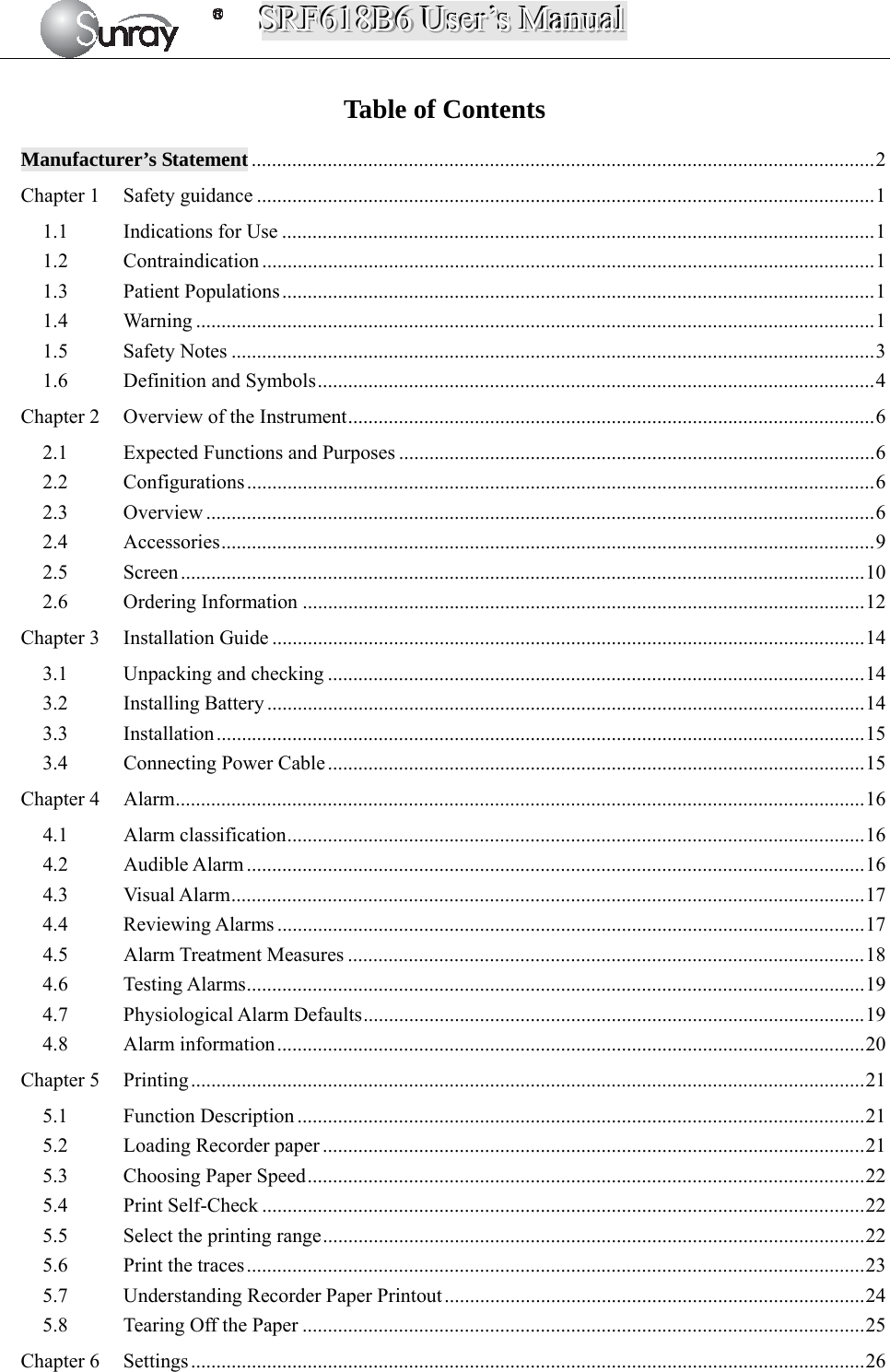
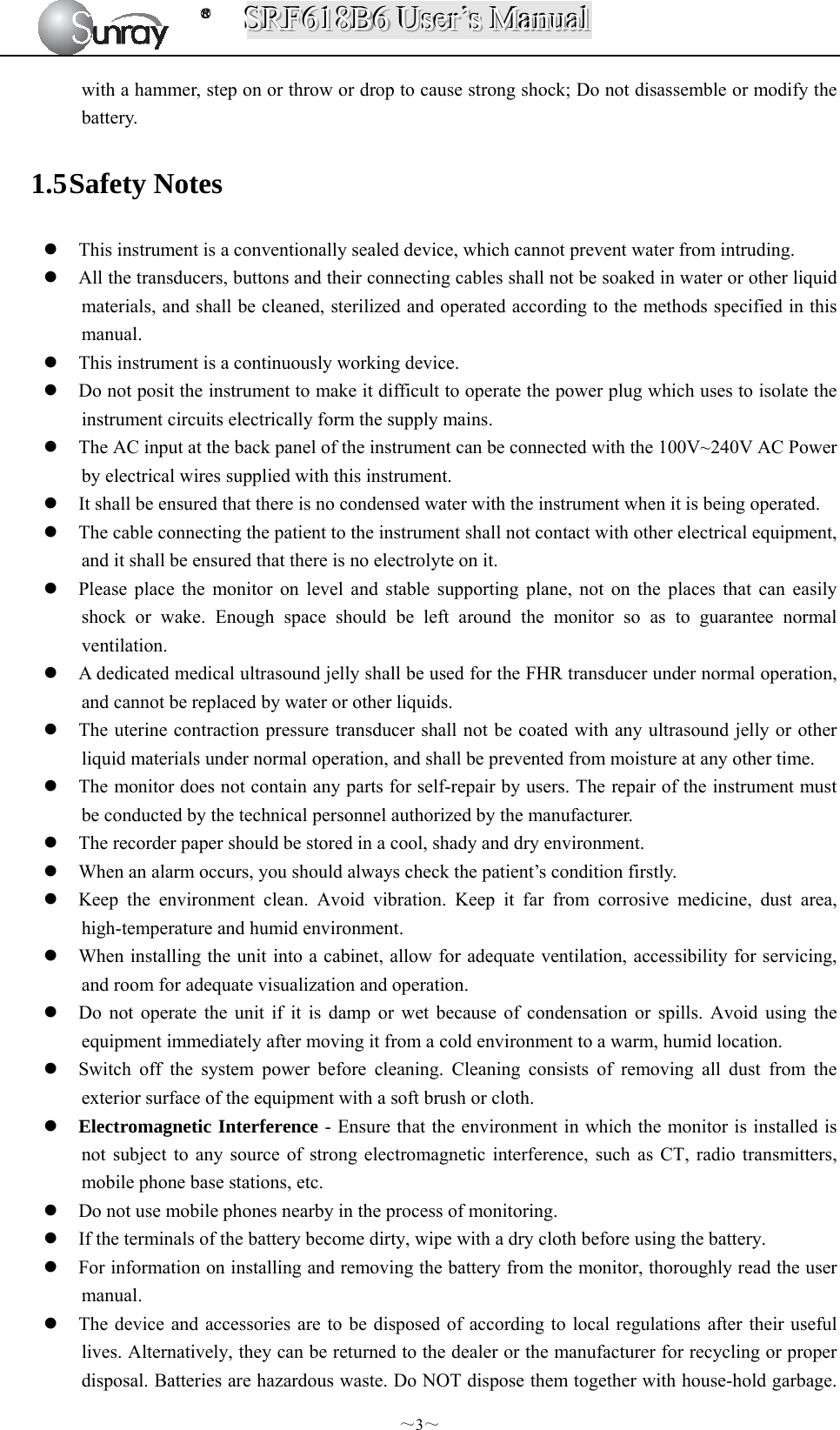
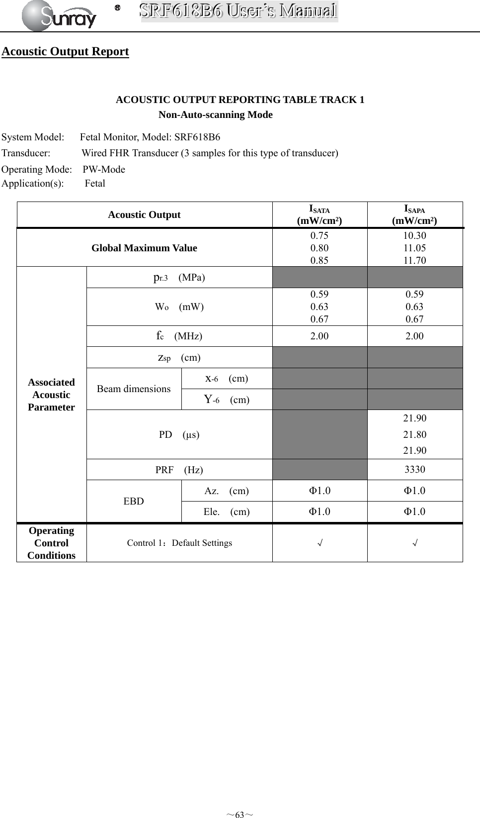
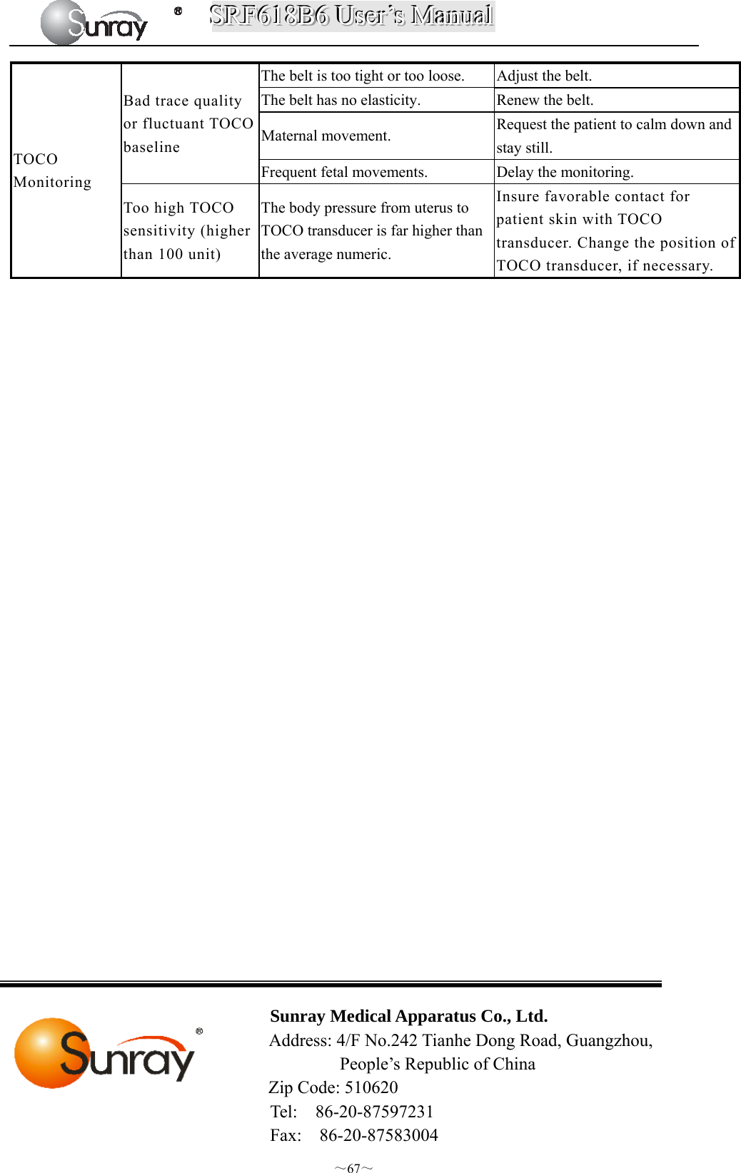
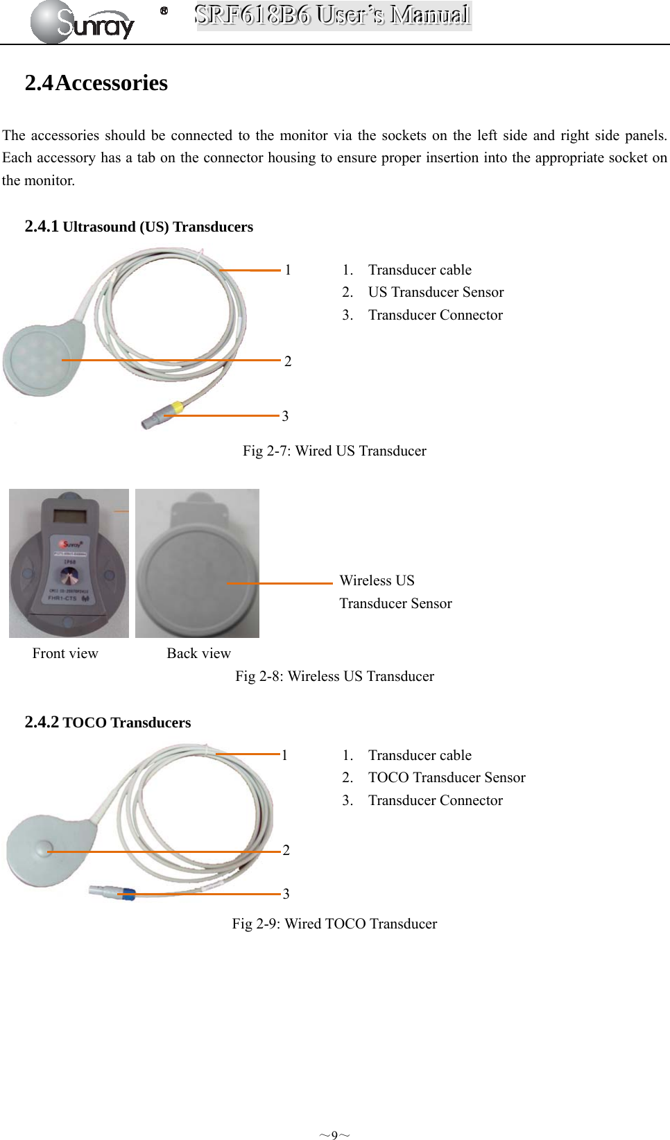
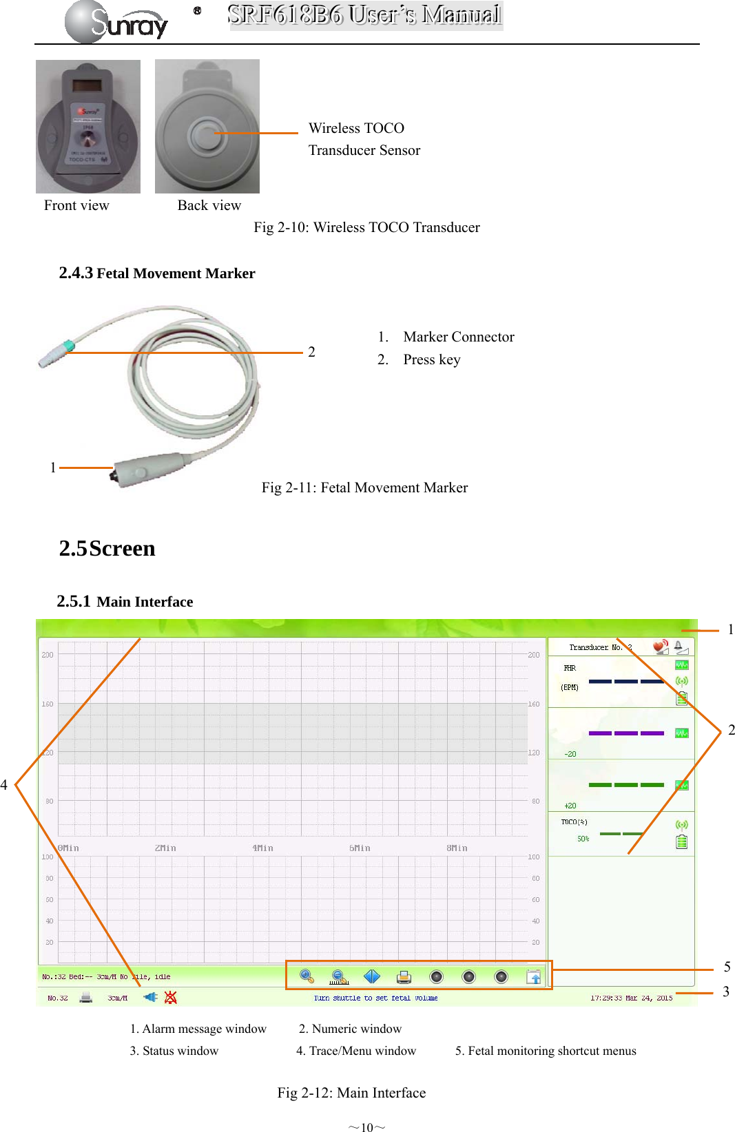
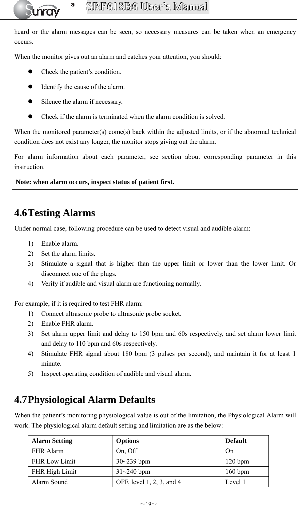
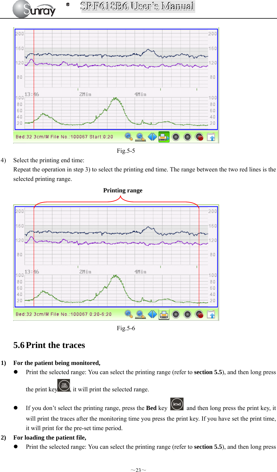
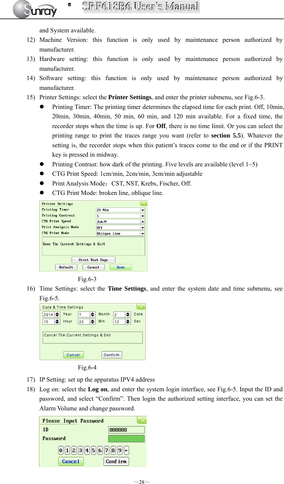
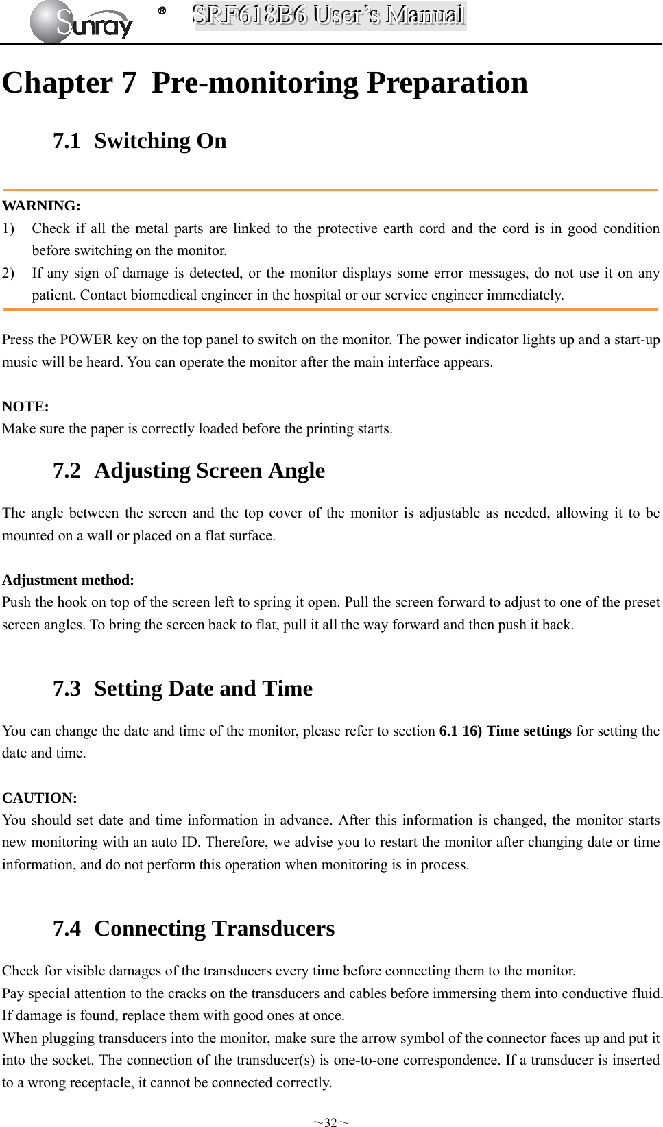
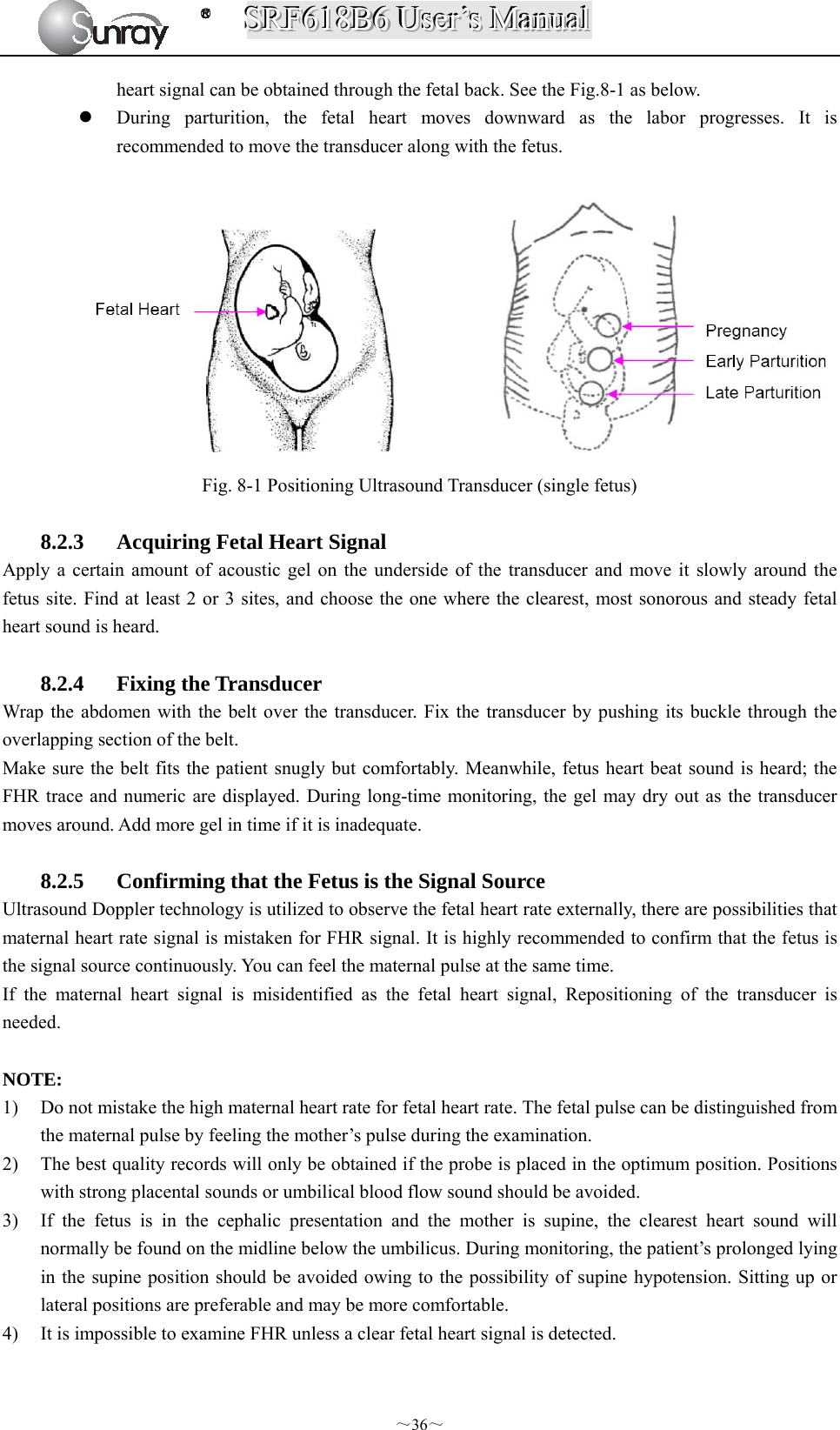
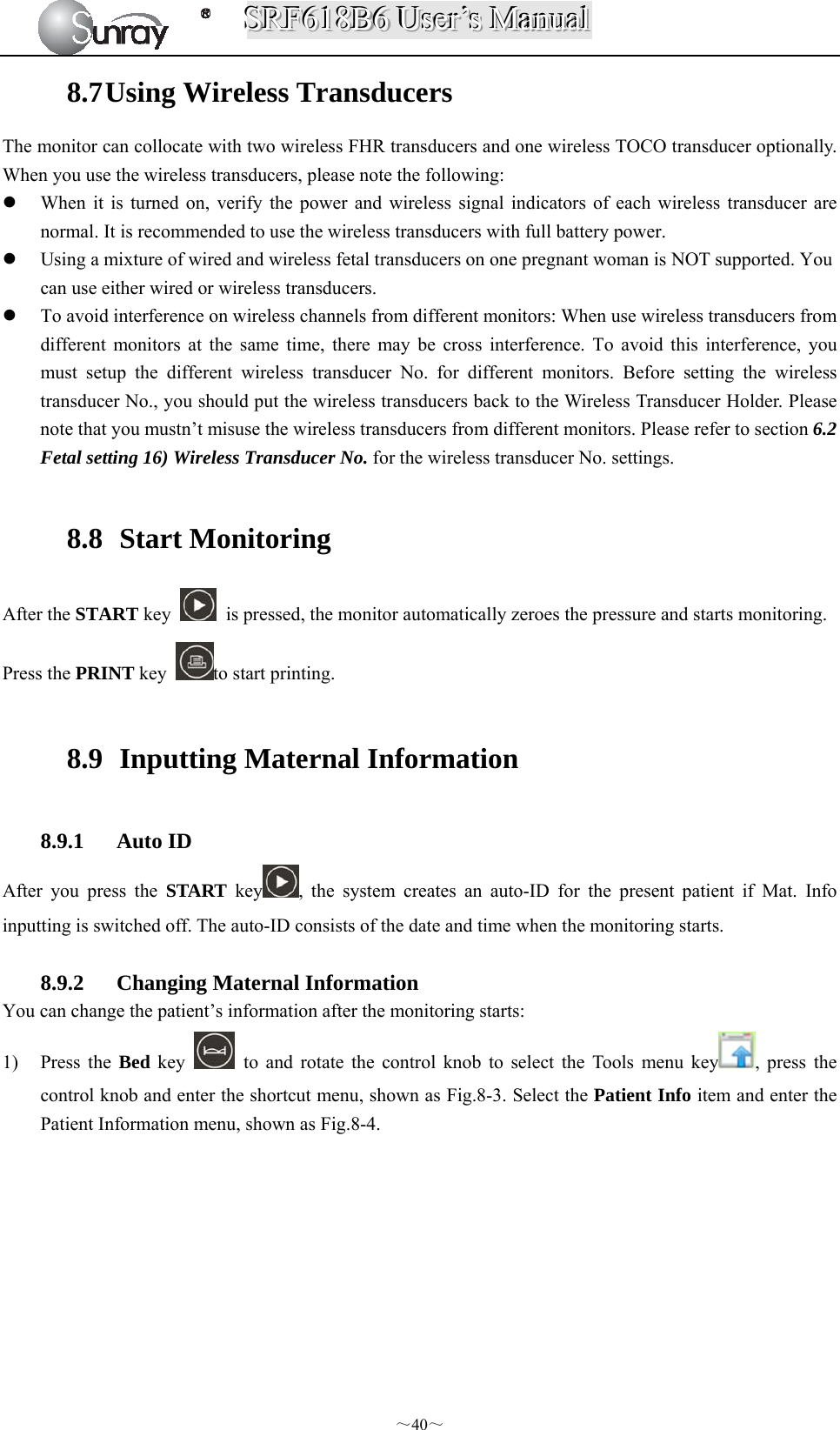
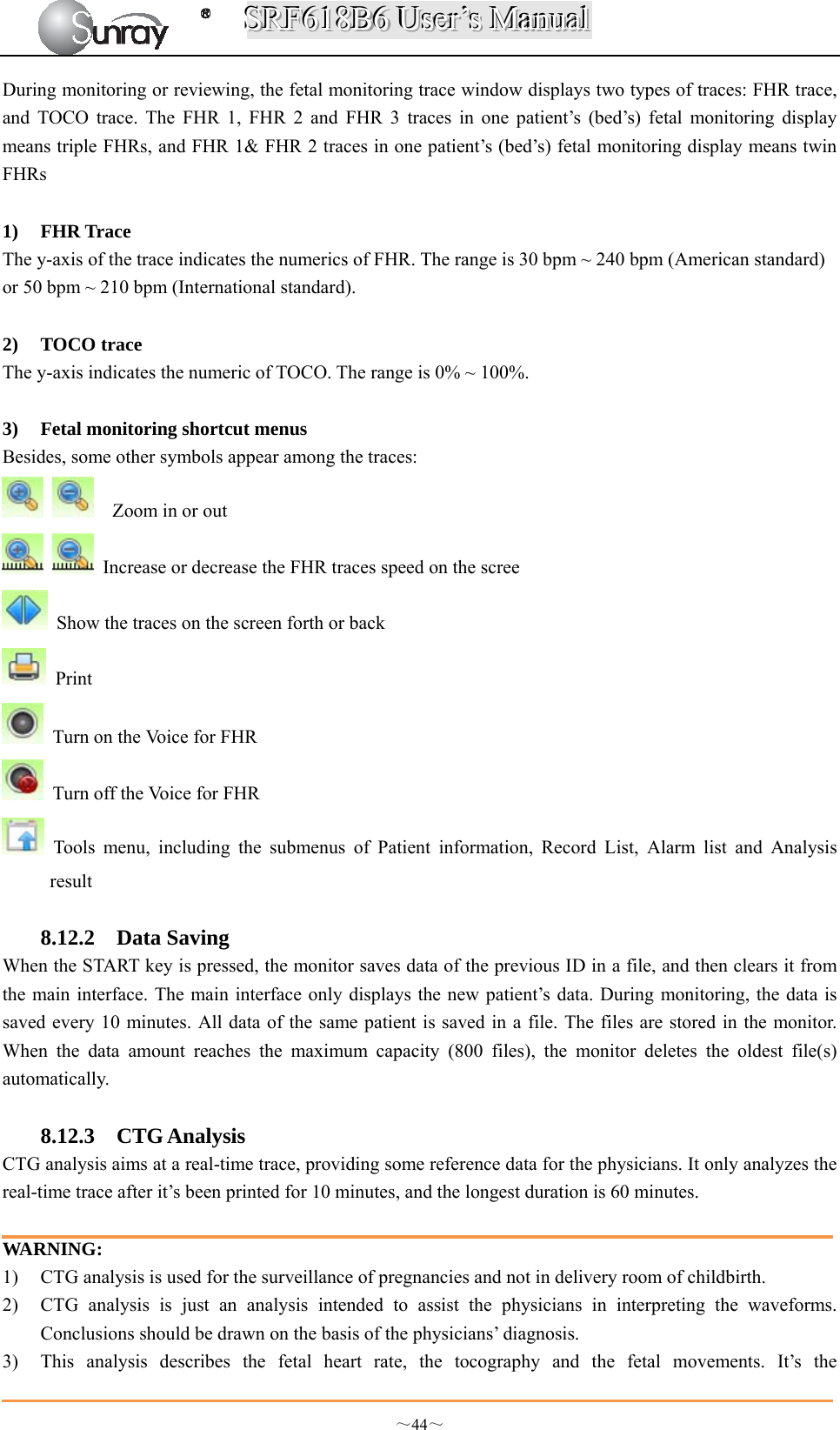
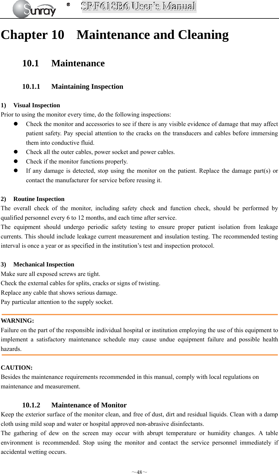
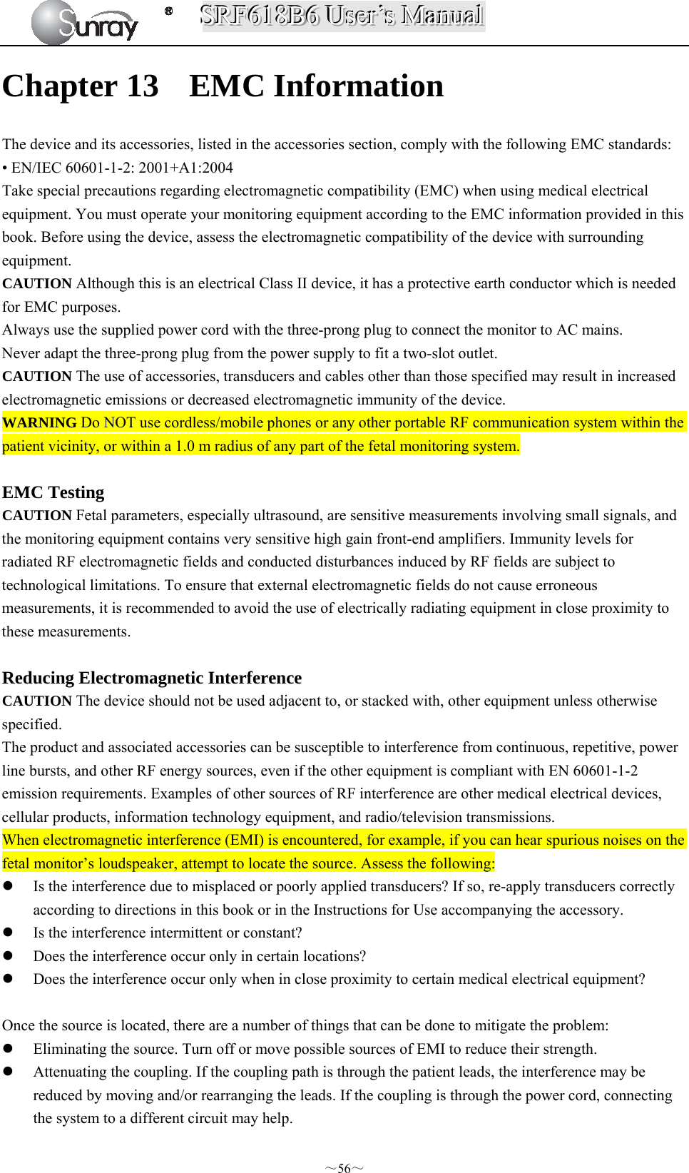
![SSSRRRFFF666111888BBB666 UUUssseeerrr’’’sss MMMaaannnuuuaaalll ~6~ Chapter 2 Overview of the Instrument 2.1 Expected Functions and Purposes The SRF618B6 Fetal Monitor provides Non-Stress testing for pregnant women from the approximately 28th week of gestation. The SRF618B6 Fetal Monitor is intended for non-invasive monitoring of the Fetal Heart Rate (FHRs), Uterine Activity (UA), and Fetal Movement (FM) during antepartum testing. Information about fetal heart rate, uterine activity, and fetal movement are all displayed on the monitor and recorded on recording paper in the form of trajectory graphic. 2.2 Configurations This user manual is written to cover the maximum configuration. The below table list the parameters and functions that are optional. 2.3 Overview [Fig. 2-1: Front view] Model Wireless transducers and the holder Monitoring twin FHRs Monitoring Triplet FHRs Built-in batterySRF618B6 Optional Optional Optional Optional 1 Alarm indicator 2 Display screen 3 Keys 4 Control knob 5 Charge, Power indicator 6 Paper drawer 7 Power key 8 Connectors (see Left Side view)](https://usermanual.wiki/Sunray-Medical-Apparatus/TOCO/User-Guide-3181403-Page-11.png)
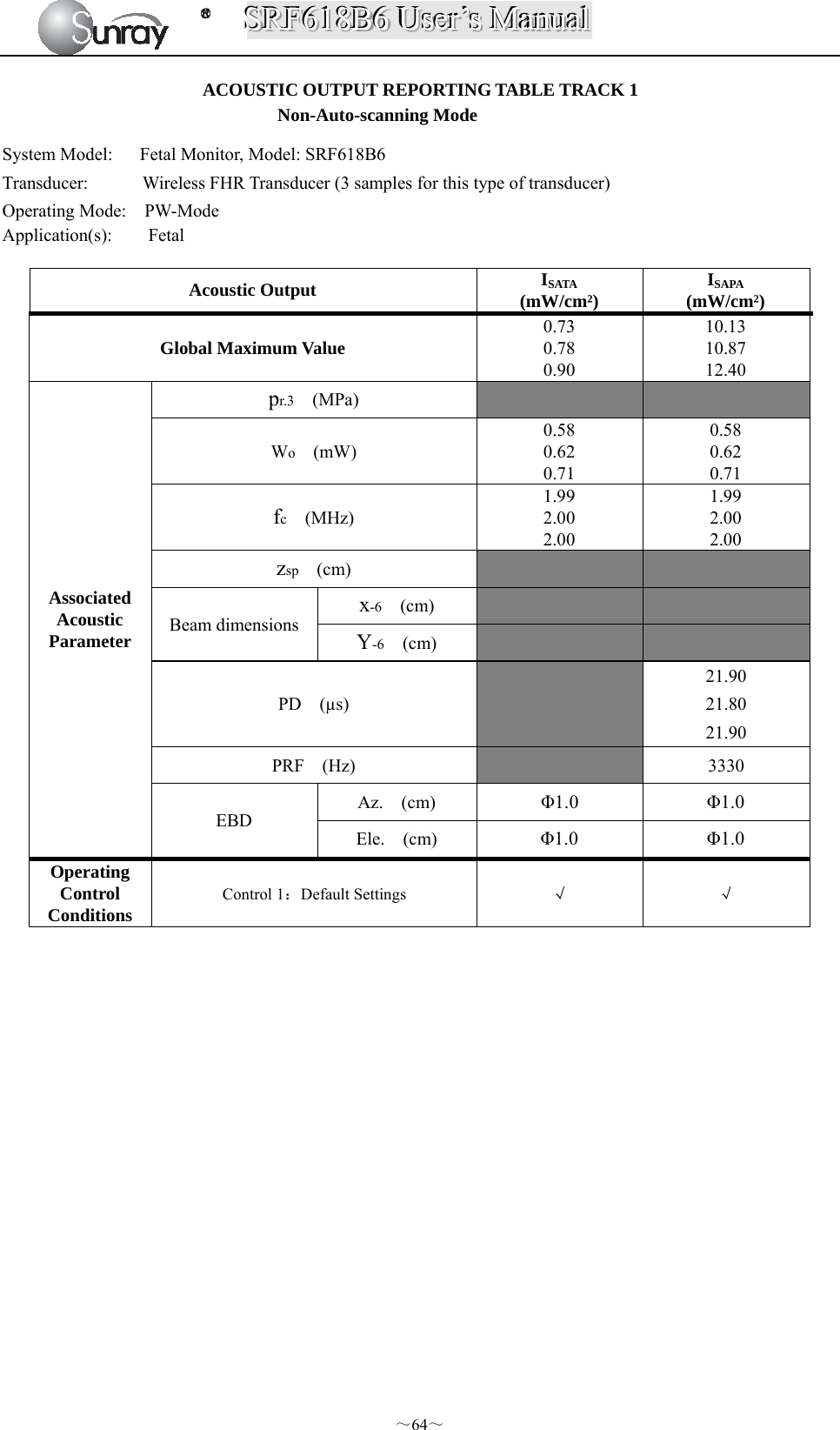
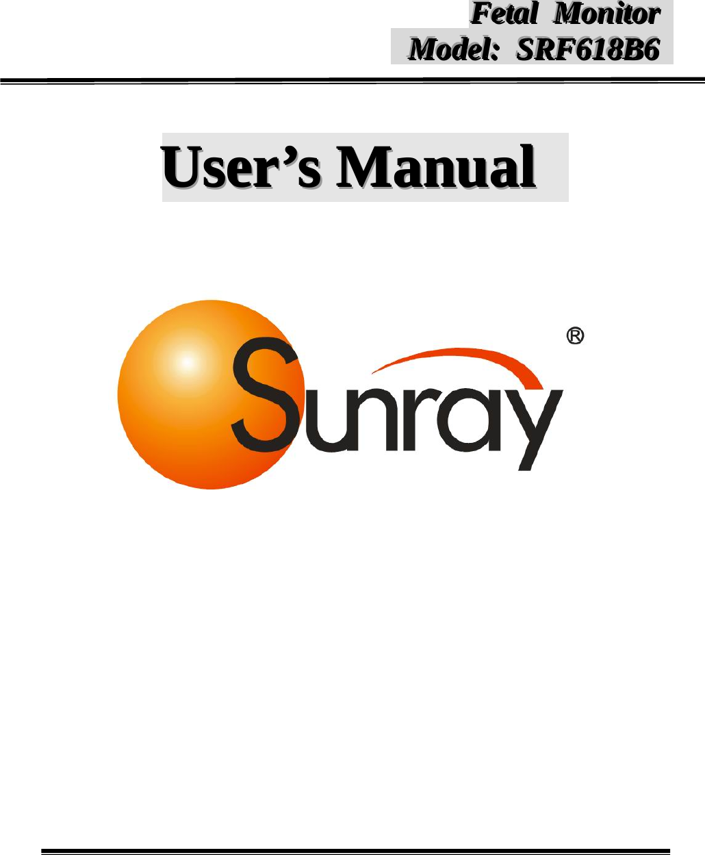
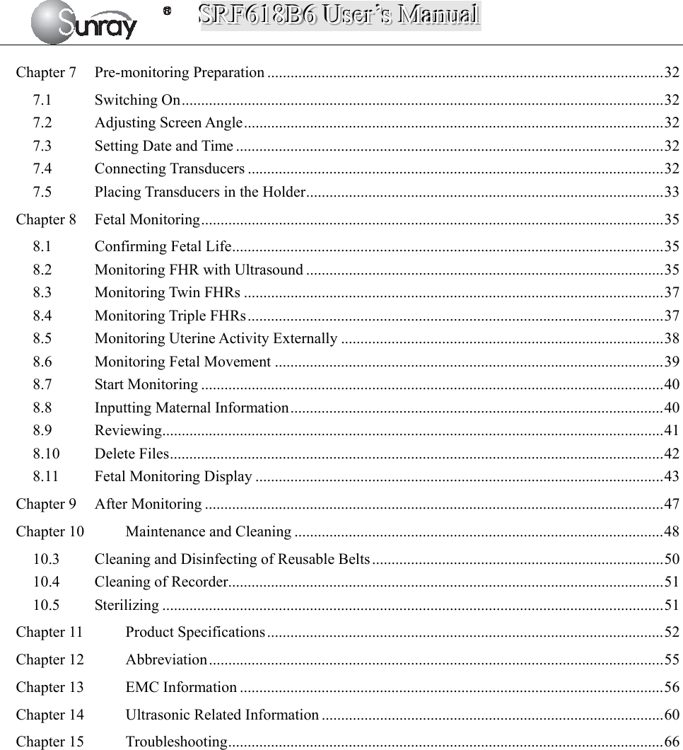
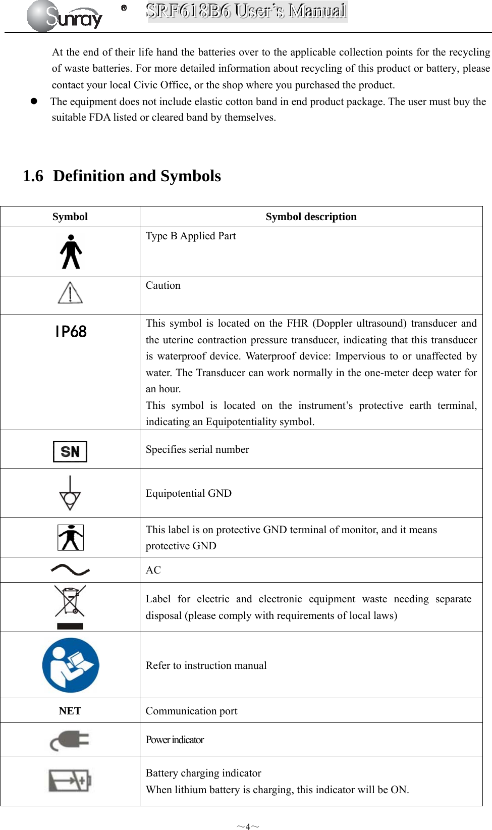
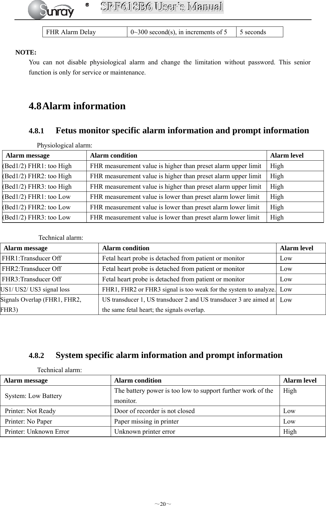
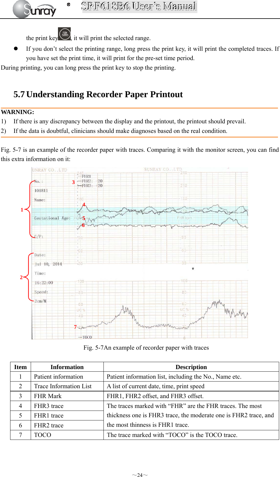
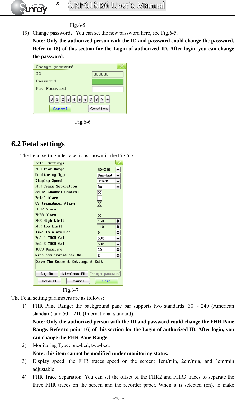
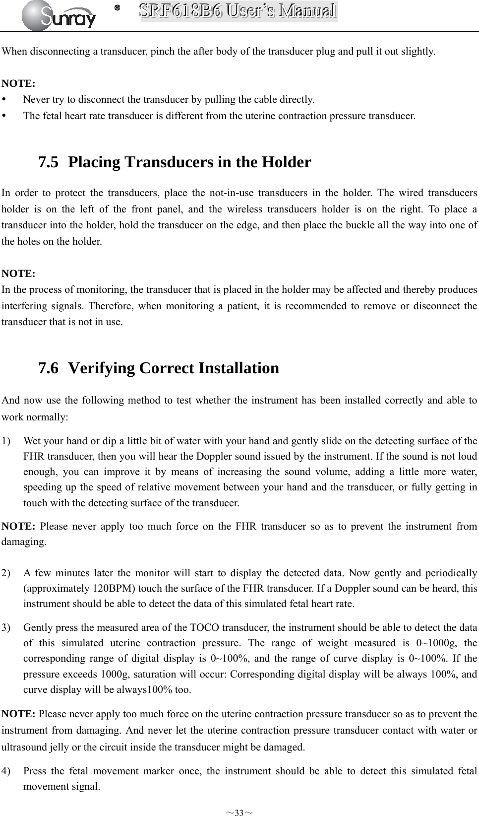
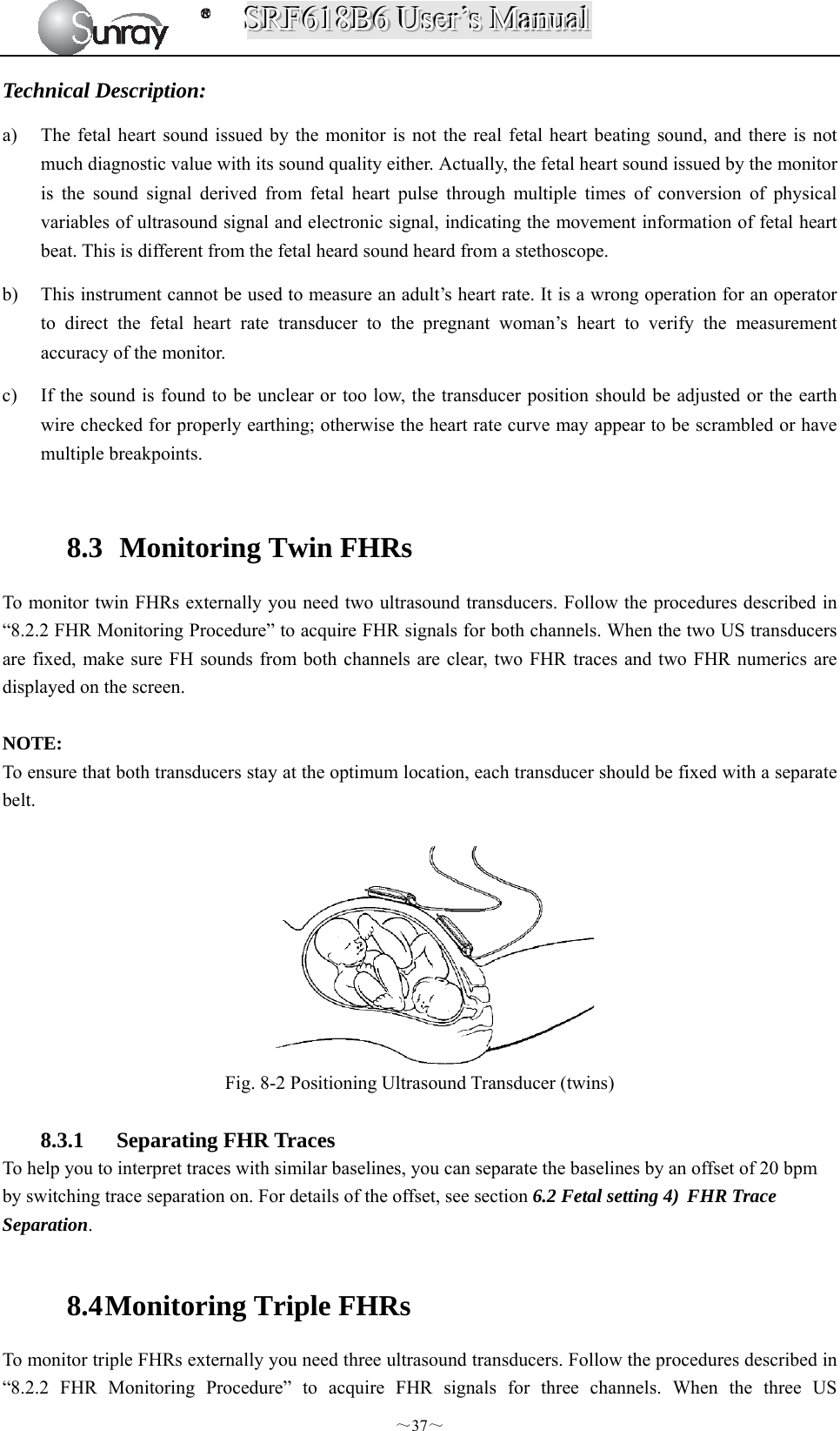
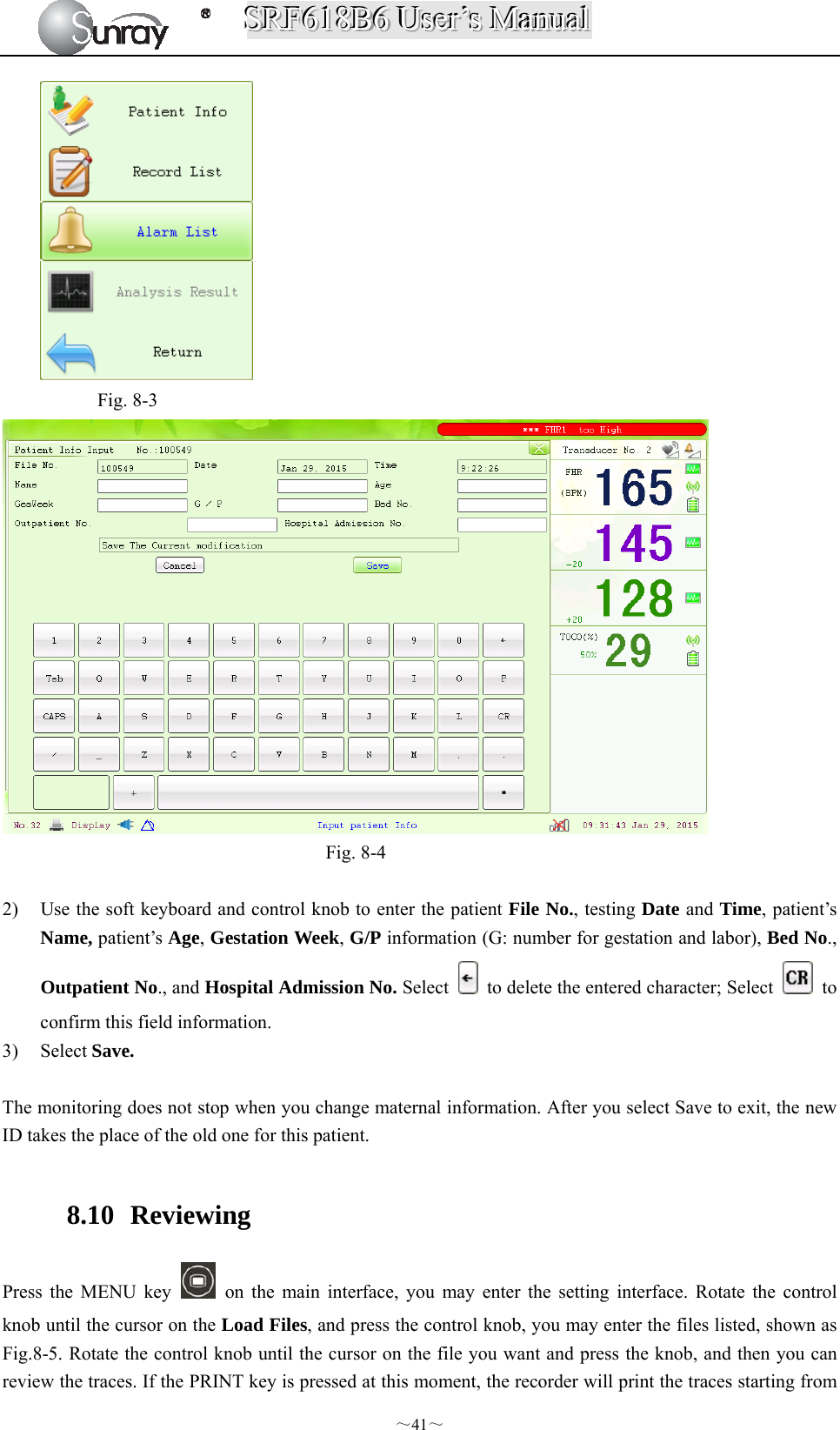
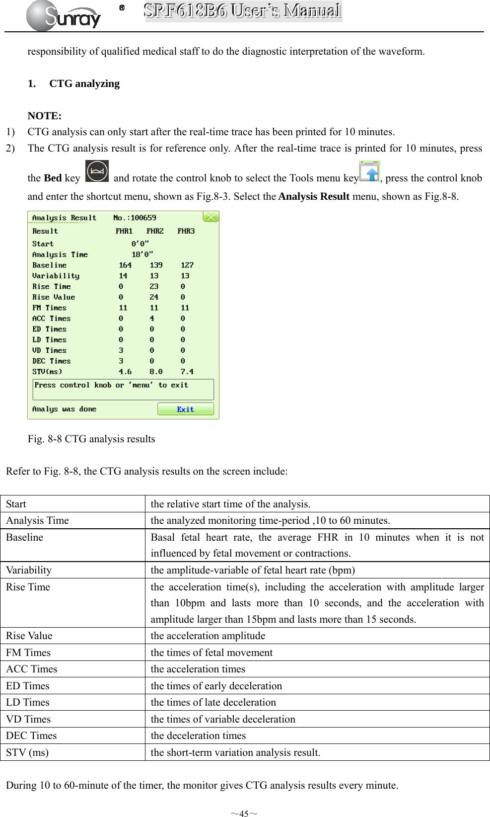
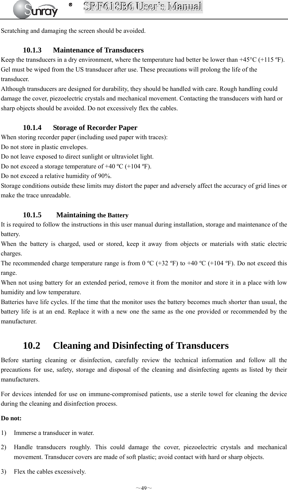
![SSSRRRFFF666111888BBB666 UUUssseeerrr’’’sss MMMaaannnuuuaaalll ~7~ [Fig.2-2: Left side view] [Fig. 2-3: Rear view] [Fig. 2-4: Bottom view] 2.3.1. Keys and Control Knob Fig. 2-5: Keys 9 FHR3 Socket 10 FHR2 Socket 11 FHR1 Socket 12 Fetal Movement Marker (FM) Socket 13 TOCO Socket 14 Wired Transducer Holder(optional) 15 Power cord connector 16 Fuse-holder 17 Handle 18 RS-232 Interface 19 RS-485 Interface 20 RJ45 Interface 21 USB Socket 22 Antenna Interface 23 Battery Component 24 Wall-mounting Holes 23 24](https://usermanual.wiki/Sunray-Medical-Apparatus/TOCO/User-Guide-3181403-Page-12.png)
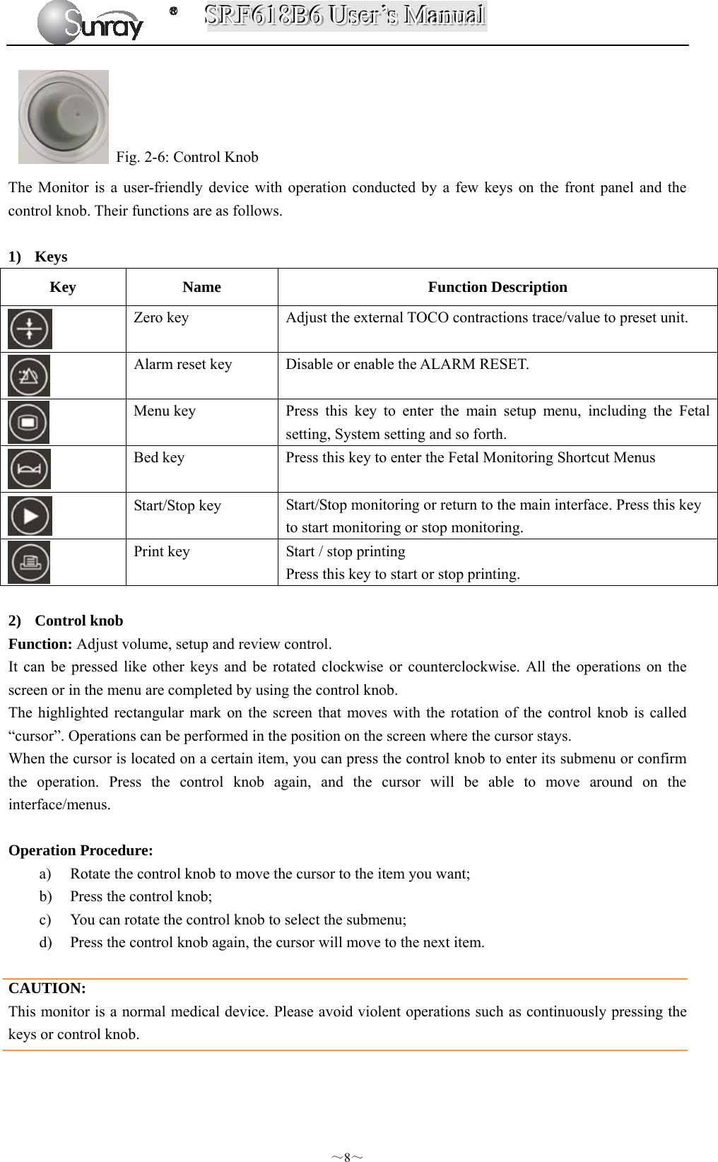


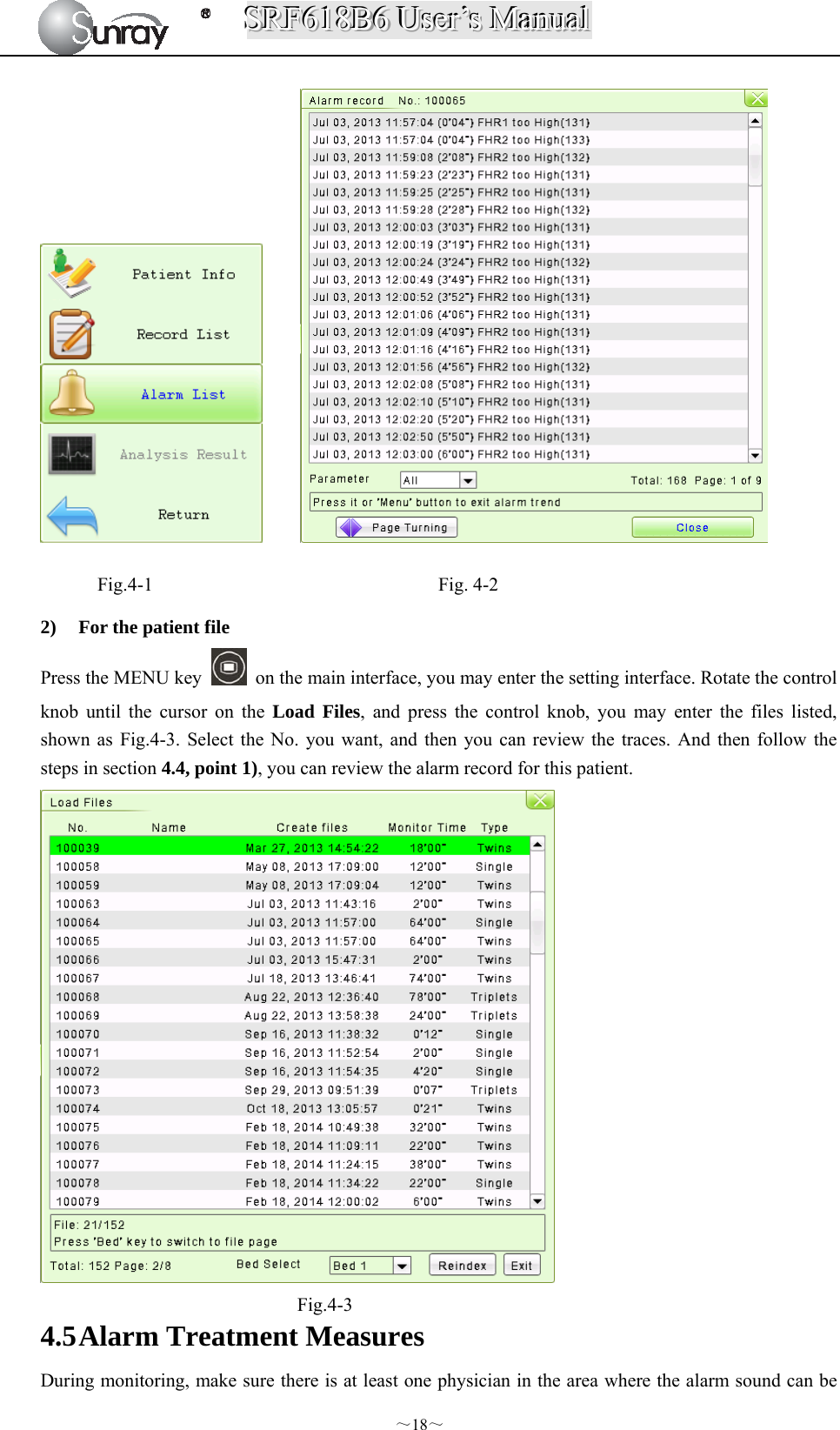
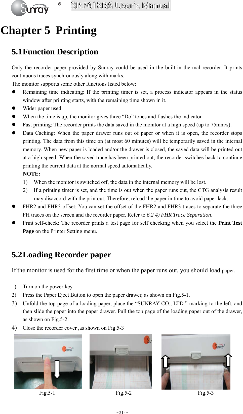

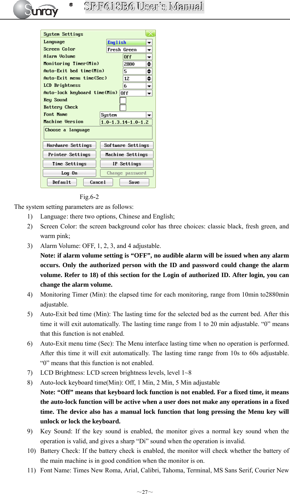
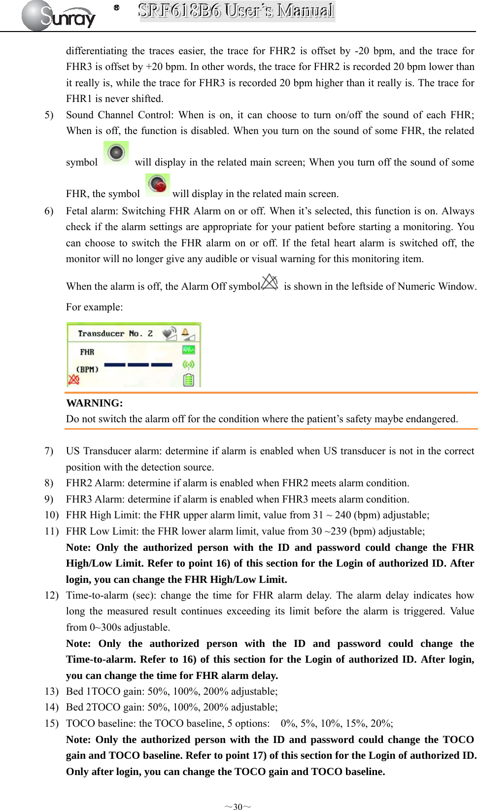
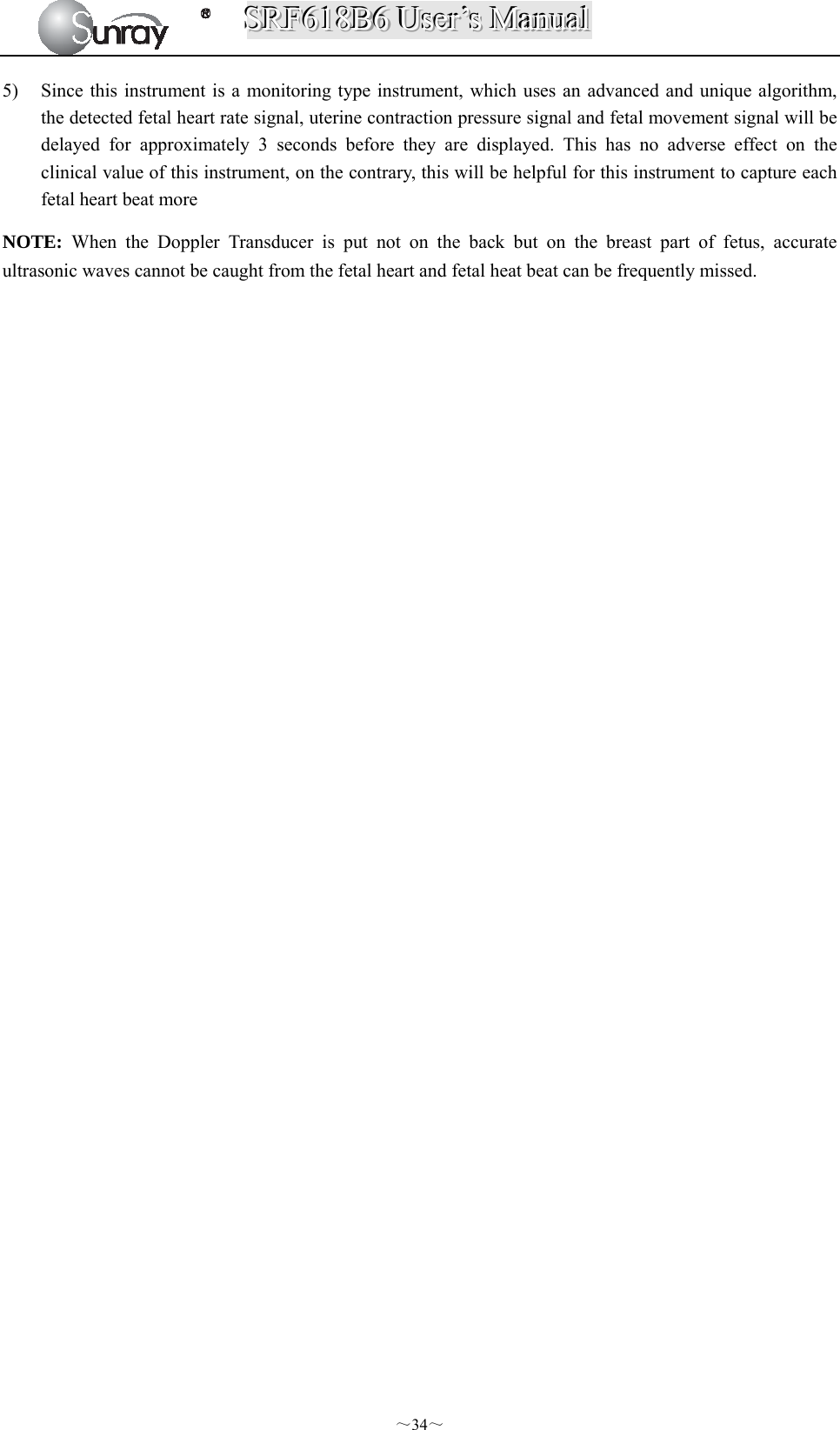
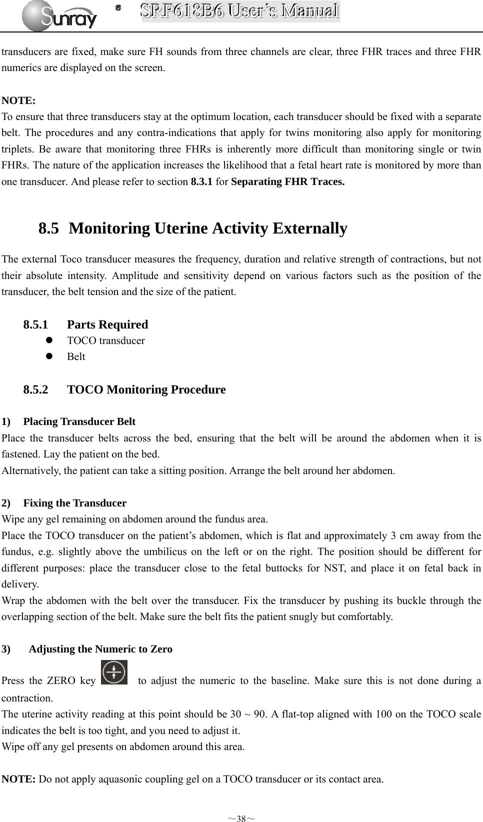
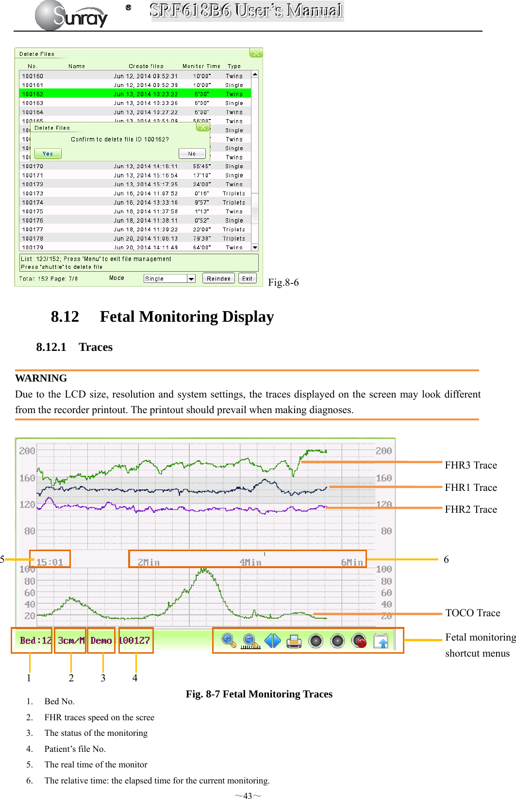
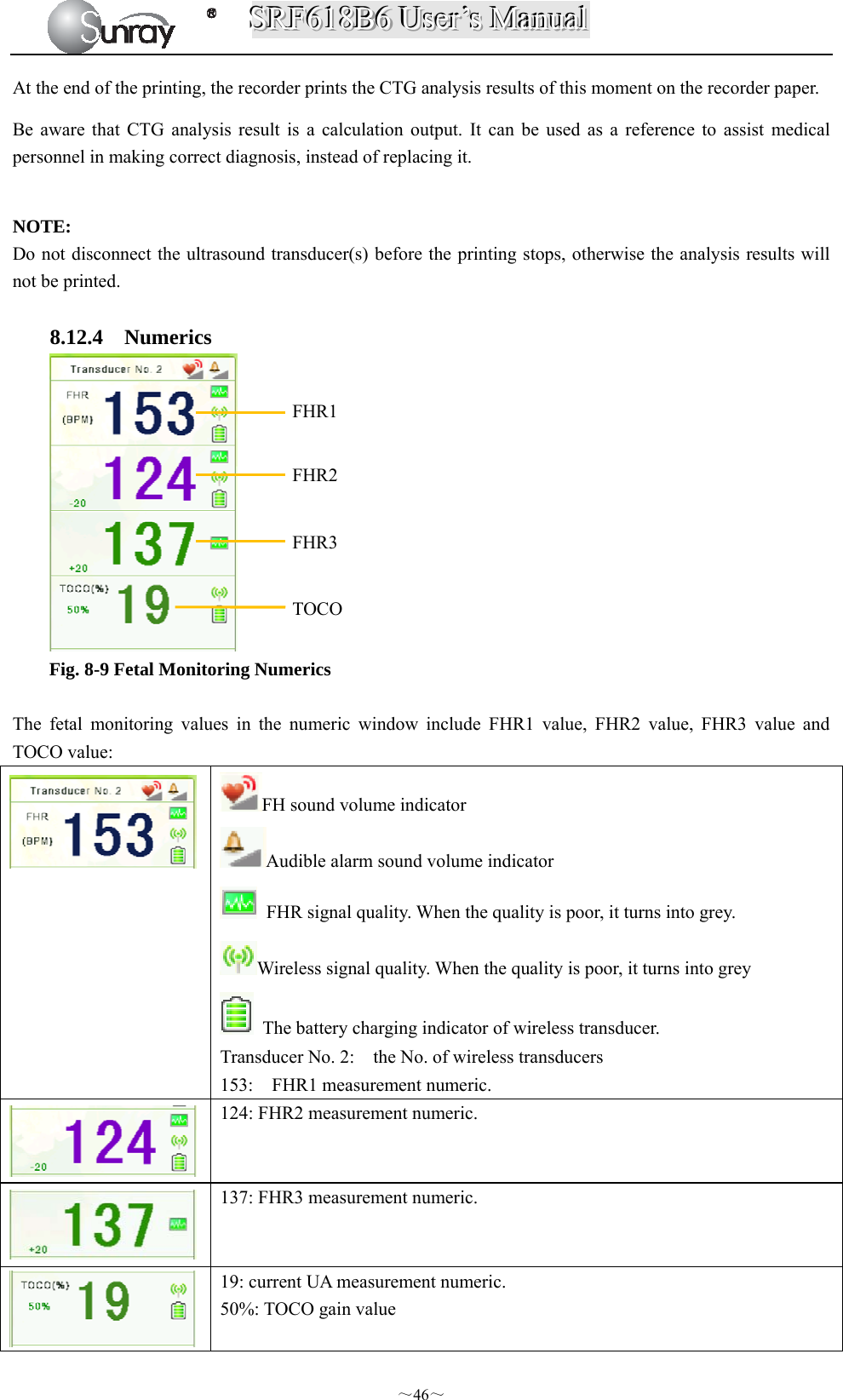
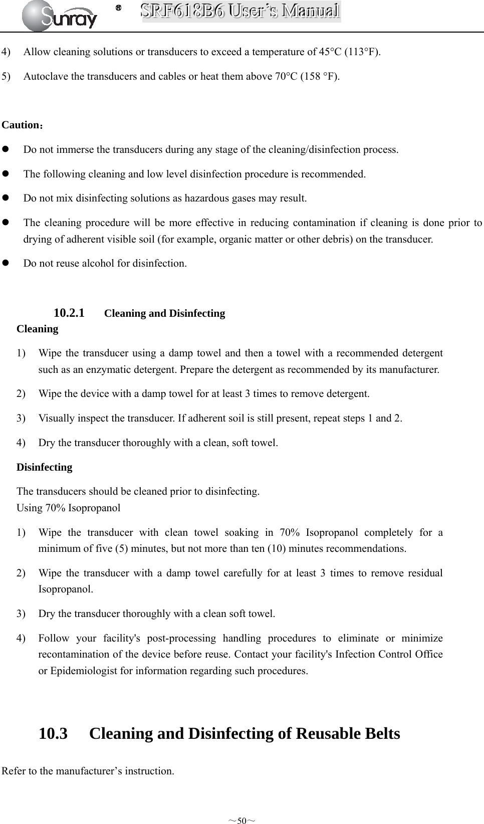
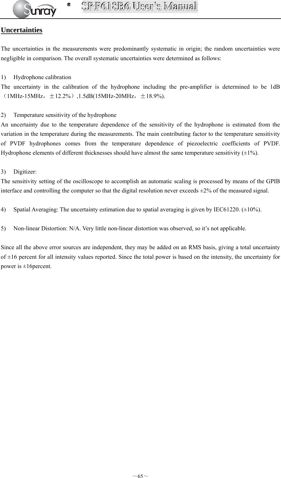
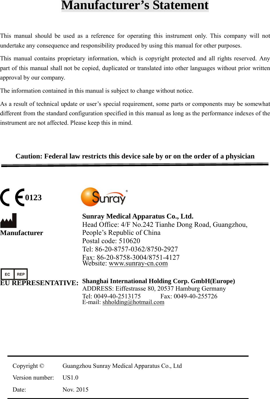
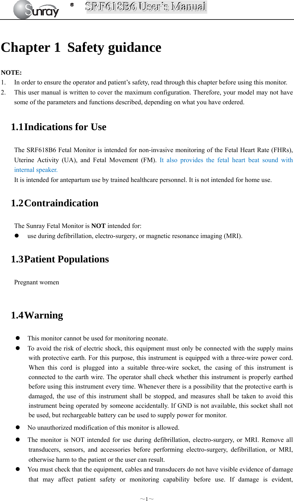
![SSSRRRFFF666111888BBB666 UUUssseeerrr’’’sss MMMaaannnuuuaaalll ~61~ ultrasound impact on these small bubbles, temperature and pressure around the space of the bubbles will increase, or even oscillate and explode, which may result in physical or chemical effects on the surrounding tissues. Relevant Parameters The main parameters related to acoustic power are: transmit frequency, transmit focus number, transmit voltage, transmit angle, element pitch, etc. These parameters vary subject to exam modes. Follow ALARA principle to select the appropriate power for scanning. A multiplicative factor applied to acoustic output parameters intended to account for ultrasonic attenuation of tissue between the source and a particular location in the tissue. In the calculation of all mechanical, the average ultrasonic attenuation is assumed to be 0.3dB/cm-MHz along the beam axis in the body. References (1) AIUM: ”Acoustic Output Measurement Standard For Diagnostic Ultrasound Equipment,” Revision 3, NEMA Standard Publication UD 2-2004, National Electrical Manufacturers Association,2004 (2) AIUM/NEMA: “Standard for real-time display of thermal and mechanical acoustic output indices on diagnostic ultrasound equipment,” Revision 2, NEMA Standard Publication UD 3-2004, National Electrical Manufacturers Association,2004 (3) Measurement and characterization of ultrasonic fields using hydrophones in the frequency range 0.5MHz to 15MHz (4) Ultrasonic Power measurement in liquids in the frequency range 0.5MHz to 25MHz (5) 5.FDA:”510(K) Guide for Measuring and Reporting the Acoustic Output Diagnostic Ultrasound Medical Devices,” Center for Devices and Radiological Health, Food and Drug Administration Statistics Statistical Analysis of Measurement Data A statistical analysis was performed on the base of a tolerance limit approach. The mean and standard deviation of the Spatial-Peak, Temporal-Average Intensityand the Spatial-Peak, Pulse-Average Intensity were found, and the upper output limits were calculated from the following formula : X= +KS Where X is the upper output parameter limit, is the average of the measured output parameter, S is the standard deviation of the measured output parameter, and K is a factor from Reference [M.G. Natrella, Experimental Statistics NBS Handbook 91, 1966 Table A-7]. When sample size is 3 and P=γ=90%, the K value was 4.258. A value of K was chosen which corresponds to a 90% probability that 90% of all probes would fall below the calculated limits X. The following table presents the calculated values using the 4.258 value for K. Table 2 Results for SRF618B6 Transducers Transducers Wired FHR Transducer Wireless FHR TransducerSample Size 3 3 Mode PW PW ISATA (mW/cm²) Mean ( ) 0.802 0.811 Std Dev (S) 0.050 0.084 Limit (X) 1.019 1.172 ISAPA (mW/cm²) Mean ( ) 11.02 11.13 Std Dev (S) 0.699 1.157 Limit (X) 13.99 16.06](https://usermanual.wiki/Sunray-Medical-Apparatus/TOCO/User-Guide-3181403-Page-66.png)