Suntech ST-100M Quad-Band GSM Module User Manual
Suntech International Ltd. Quad-Band GSM Module
UserManual.wiki
>
Suntech
>
ST 100M User Manual
User Manual
Navigation menu
Upload a User Manual
Namespaces
Wiki Guide
HTML
PDF
Info
Views
User Manual
Discussion / Help
Navigation
![ST-100M Module 71 Introduction 1.1 Overview This document introduces the supported AT command set of MAUI project. 1.2 References z [1] 3GPP TS 27.007 V3.13.0 (2003-03) z [2] ETSI TS 27.005 V3.1.0 (2000-01) z [3] ITU-T V.25 ter (07/1997)](https://usermanual.wiki/Suntech/ST-100M/User-Guide-946988-Page-7.png)
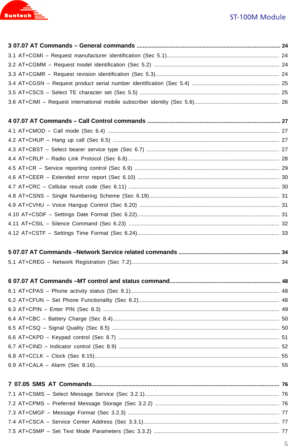
![ST-100M Module 92.2.3 Field Type Short name Parameter/comment String dial string .0 1 2 3 4 5 6 7 8 9 +. Valid characters for origination W The W modifier is ignored but is included for compatibility reasons only , The comma modifier is ignored but is included for compatibility reasons only ; Informs the Infrared Modem that the number is a voice number rather than a fax or data number T The T modifier is ignored but is included only for compatibility purposes P The P modifier is ignored but is included only for compatibility purposes String text 28800 Connected with data bit rate of 28800 bits/s (HSCSD) 19200 Connected with data bit rate of 19200 bits/s (HSCSD) 14400 Connected with data bit rate of 14400 bits/s (HSCSD) 9600 Connected with data bit rate of 9600 bits/s 4800 Connected with data bit rate of 4800 bits/s 2400 Connected with data bit rate of 2400 bits/s 2.2.4 Response Execution command : CONNECT CONNECT <text> NO CARRIER ERROR OK 2.3 ATE 2.3.1 Description The setting of this parameter determines whether or not the DCE echoes characters received from the DTE during command state and online command state. 2.3.2 Format Execution command : ATE[<value>]](https://usermanual.wiki/Suntech/ST-100M/User-Guide-946988-Page-9.png)
![ST-100M Module 102.3.2 Field Type Short name Parameter/comment Integer value 0 DCE does not echo characters during command state and online command state. 1 DCE echoes characters during command state and online command state. 2.3.4 Response Execution command : OK 2.4 ATH 2.4.1 Description Terminates a connection. 2.4.2 Format Execution command : ATH 2.4.3 Response Execution command : NO CARRIER OK 2.5 ATI 2.5.1 Description Request Identification Information. 2.5.2 Format Execution command : ATI[<value>] 2.5.3 Field Type Short name Parameter/comment Integer value used to select from among multiple types of identifying information String text product information](https://usermanual.wiki/Suntech/ST-100M/User-Guide-946988-Page-10.png)
![ST-100M Module 112.5.4 Response Execution command : <text> 2.6 ATL 2.6.1 Description Set volume of the monitor speaker. 2.6.2 Format Execution command : ATL[<value>] 2.6.3 Field Type Short name Parameter/comment Integer value 0 Low speaker volume 1 Low speaker volume 2 Medium speaker volume 3 High speaker volume 2.6.4 Response Execution command : OK 2.7 ATO 2.7.1 Description Switch from on-line command mode to on-line data mode during an active call. Returns ERROR when not in on-line command mode. 2.7.2 Format Execution command : ATO 2.7.3 Field Type Short name Parameter/comment String text 28800 Connected with data bit rate of 28800 bits/s (HSCSD) 19200 Connected with data bit rate of 19200 bits/s (HSCSD) 14400 Connected with data bit rate of 14400 bits/s (HSCSD) 9600 Connected with data bit rate of 9600 bits/s 4800 Connected with data bit rate of 4800 bits/s 2400 Connected with data bit rate of 2400 bits/s](https://usermanual.wiki/Suntech/ST-100M/User-Guide-946988-Page-11.png)
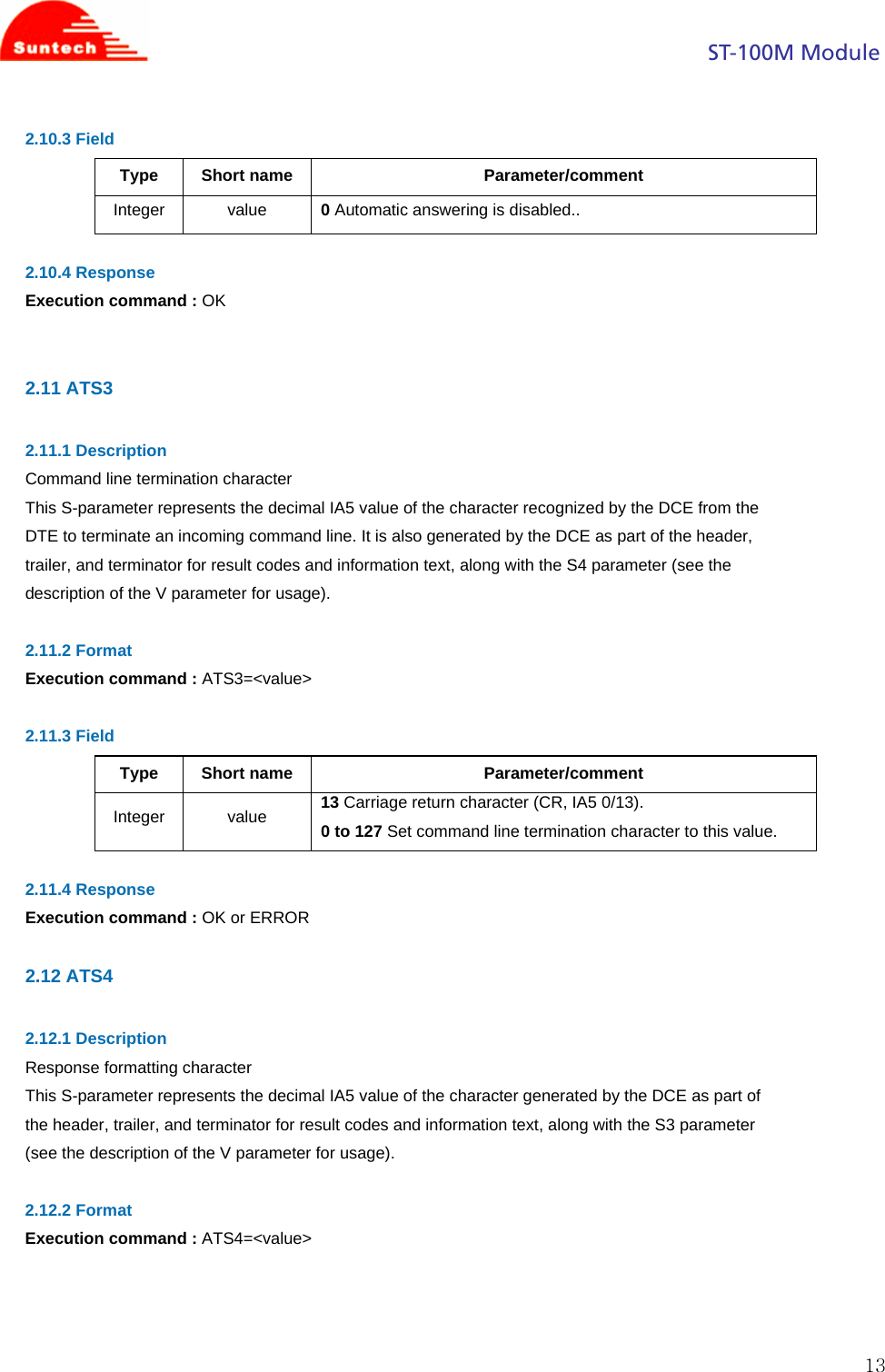
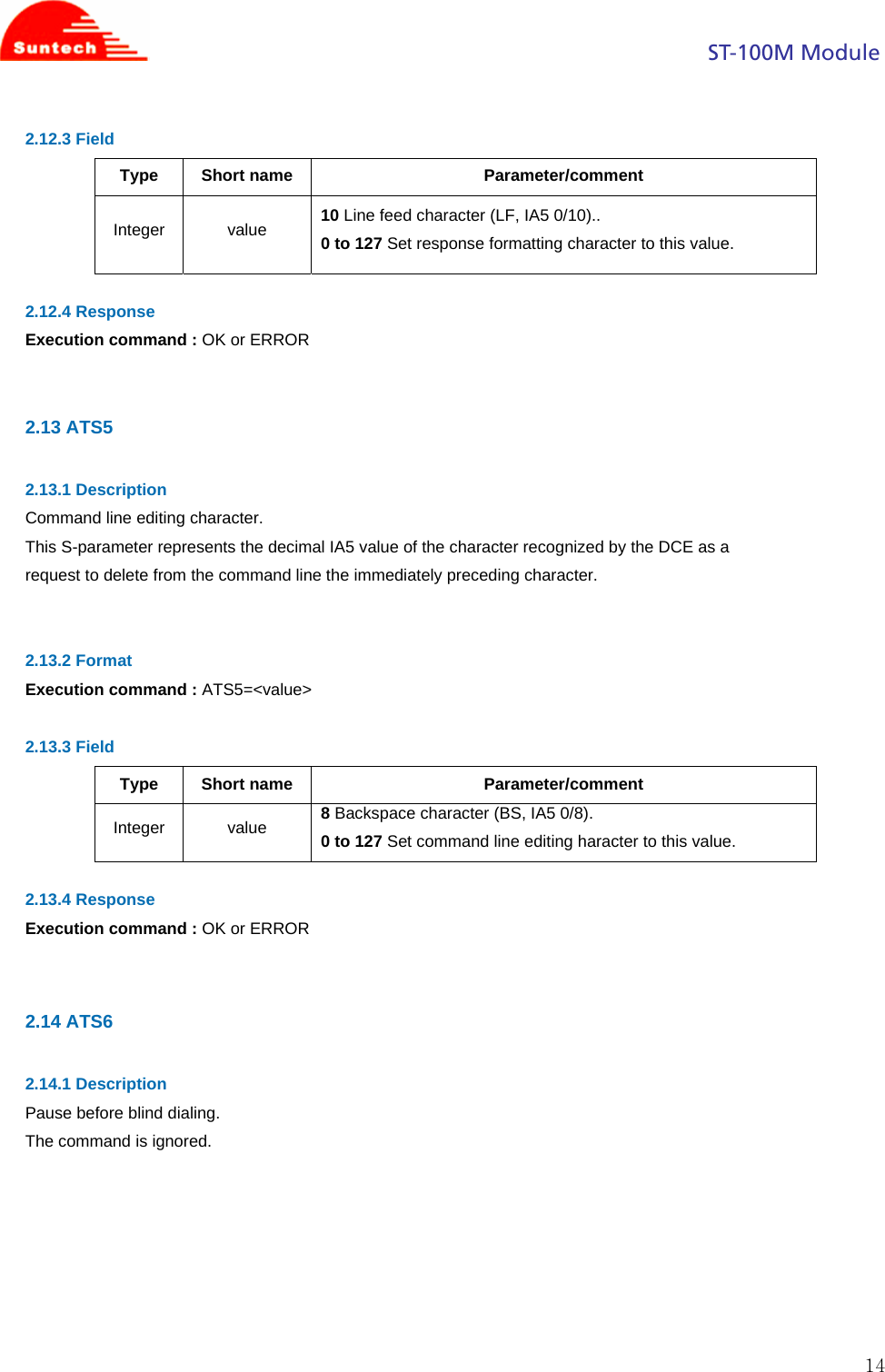
![ST-100M Module 122.7.4 Response Execution command : CONNECT CONNECT <text> NO CARRIER ERROR 2.8 ATP 2.8.1 Description Select pulse dialing. (This setting is ignored.) 2.9 ATQ 2.9.1 Description Set result code suppression mode. 2.9.2 Format Execution command : ATQ[<value>] 2.9.3 Field Type Short name Parameter/comment Integer value 0 DCE transmits result codes. 1 Result codes are suppressed and not transmitted. 2.9.4 Response Execution command : OK 2.10 ATS0 2.10.1 Description Automatic answer. This S-parameter controls the automatic answering feature of the DCE. If set to 0, automatic answering is disabled. If set to a non-zero value, the DCE shall cause the DCE to answer when the incoming call indication (ring) has occurred the number of times indicated by the value. 2.10.2 Format Execution command : ATS0=<value>](https://usermanual.wiki/Suntech/ST-100M/User-Guide-946988-Page-12.png)

![ST-100M Module 162.16.4 Response Execution command : OK or ERROR 2.17 ATS10 2.17.1 Description Automatic disconnect delay. This parameter specifies the amount of time, in tenths of a second, that the DCE will remain connected to the line (off-hook) after the DCE has indicated the absence of received line signal. If the received line signal is once again detected before the time specified in S10 expires, the DCE remains connected to the line and the call continues. 2.17.2 Format Execution command : ATS10=<value> 2.17.3 Field Type Short name Parameter/comment Integer value 1 to 254 Number of tenths of a second of delay. 2.17.4 Response Execution command : OK or ERROR 2.18 ATT 2.18.1 Description We do not support. This setting is ignored. 2.19 ATV 2.19.1 Description Set DCE response format. 2.19.2 Format Execution command : ATV[<value>]](https://usermanual.wiki/Suntech/ST-100M/User-Guide-946988-Page-16.png)
![ST-100M Module 172.19.3 Field Type Short name Parameter/comment Integer value 0 DCE transmits limited headers and trailers and numeric text. 1 DCE transmits full headers and trailers and verbose response text. 2.19.4 Response Execution command : OK 2.20 ATX 2.20.1 Description The setting of this parameter determines whether or not the DCE transmits particular result codes to the DTE. It also controls whether or not the DCE verifies the presence of dial tone when it first goes off-hook to begin dialing, and whether or not engaged tone (busy signal) detection is enabled. However, this setting has no effect on the operation of the W dial modifier, which always checks for dial tone regardless of this setting, nor on the busy signal detection capability of the W and @ dial modifiers. See Table. 2.20.2 Format Execution command : ATX[<value>] 2.20.3 Field Type Short name Parameter/comment Integer value 0 CONNECT result code is given upon entering online data state. Dial tone and busy detection are disabled. 1 CONNECT <text> result code is given upon entering online data state. Dial tone and busy detection are disabled. 2 CONNECT <text> result code is given upon entering online data state. Dial tone detection is enabled, and busy detection is disabled. 3 CONNECT <text> result code is given upon entering online data state. Dial tone detection is disabled, and busy detection is enabled. 4 CONNECT <text> result code is given upon entering online data state. Dial tone and busy detection are both enabled.](https://usermanual.wiki/Suntech/ST-100M/User-Guide-946988-Page-17.png)
![ST-100M Module 182.20.4 Response Execution command : OK or ERROR 2.21 ATZ 2.21.1 Description Reset to default configuration 2.21.2 Format Execution command : ATZ[<value>] 2.21.3 Field Type Short name Parameter/comment Integer value 0 Set parameters to factory defaults. 2.21.4 Response Execution command : OK or ERROR 2.22 AT&F 2.22.1 Description Set to factory-defined configuration 2.22.2 Format Set command : AT&F[<value>] 2.22.3 Field Type Short name Parameter/comment Integer value 0 Set parameters to factory defaults. 2.22.4 Response Set command: OK | ERROR | +CME ERROR: <err>](https://usermanual.wiki/Suntech/ST-100M/User-Guide-946988-Page-18.png)
![ST-100M Module 192.23 AT+GMI 2.23.1 Description Same as AT+CGMI 2.24 AT+GMM 2.24.1 Description Same as AT+CGMM 2.25 AT+GMR 2.25.1 Description Same as AT+CGMR 2.26 AT+IPR 2.26.1 Description Specifies the data rate, in addition to 1200 bits/s or 9600 bits/s, at which the DCE will accept commands. May be used to select operation at rates at which the DCE is not capable of automatically detecting the data rate being used by the DTE. 2.26.2 Format Execution command : AT+IPR=[<rate>] Read command : AT+IPR? Displays the current <rate> setting. Test command : AT+IPR=? Shows if the command is supported. 2.26.3 Field Type Short name Parameter/comment Integer rate The rate, in bits per second, at which the DTE-DCE interface should operate. Currently, the following rates are supported: 0, 300, 1200, 2400, 4800, 9600, 14400, 19200, 28800, 38400, 57600, 115200, 230400, and 460800. If unspecified, or set to zero, automatic detection is selected, and the character format is](https://usermanual.wiki/Suntech/ST-100M/User-Guide-946988-Page-19.png)
![ST-100M Module 20forced to auto-detect (AT+ICF=0) 2.26.4 Response Execution command : OK Read command : +IPR: <rate> Test command : +IPR: (list of supported <rate>s) 2.27 AT+ICF 2.27.1 Description Determines the local serial-port asynchronous character framing. 2.27.2 Format Execution command : AT+ICF=[<format>[,<parity>]] Read command : AT+ICF? Displays the current <format>, <parity> settings. Test command : AT+ICF=? Shows if the command is supported. 2.27.3 Field Type Short name Parameter/comment Integer parity 0 Auto-detect 1 8 Data bits, 2 Stop bits 2 8 Data bits, 1 Parity bit, 1 Stop bit 3 8 Data bits, 1 Stop bit Default setting 4 7 Data bits, 2 Stop bits 5 7 Data bits, 1 Parity bit, 1 Stop bit 6 7 Data bits, 1 Stop bit Integer parity 0 Odd Default setting 1 Even 2 Mark 3 Space 2.27.4 Response Execution command : OK Read command : +ICF: <format>,<parity> Test command : +ICF: (list of supported <format>s), (list of supported <parity>s)](https://usermanual.wiki/Suntech/ST-100M/User-Guide-946988-Page-20.png)
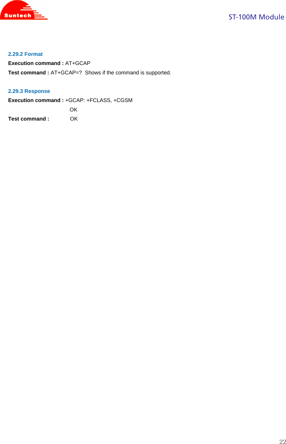
![ST-100M Module 212.28 AT+DS 2.28.1 Description Controls the V.42 bis data compression function, if provided in the TA. 2.28.2 Format Execution command : AT+DS=[<direction>[,<compression_negotiation>[,<max_dict>[,<max-string>]]]] Read command : AT+DS? Displays the current <direction>, <compression_negotiation>, <max_dict>, and <max_string> settings. Test command : AT+DS=? Shows if the command is supported. 2.28.3 Field Type Short name Parameter/comment Integer direction 0 Disable V.42bis 1 Enable V.42bis in transmit direction only 2 Enable V.42bis in receive direction only 3 Enable V.42bis compression in both directions Default setting Integer Compression_ negotiation 0 Accept connection if compression is negotiated according to direction Default setting 1 Disconnect if compression is not negotiated according to direction Integer max_dict 512 to 4096 Maximum dictionary size 1024 Default setting Integer max_string 6 to 250 Maximum string length 32 Default setting 2.28.4 Response Execution command : OK Read command : +DS: <direction>,<compression_negotiation>,<max-dict>,<max_string> Test command : +DS: (list of supported <direction>s),(list of supported <compression_negotiation>s),(list of supported <max_dict>s),(list of supported <max_string>s) 2.29 AT+GCAP 2.29.1 Description Request complete capabilities list.](https://usermanual.wiki/Suntech/ST-100M/User-Guide-946988-Page-21.png)
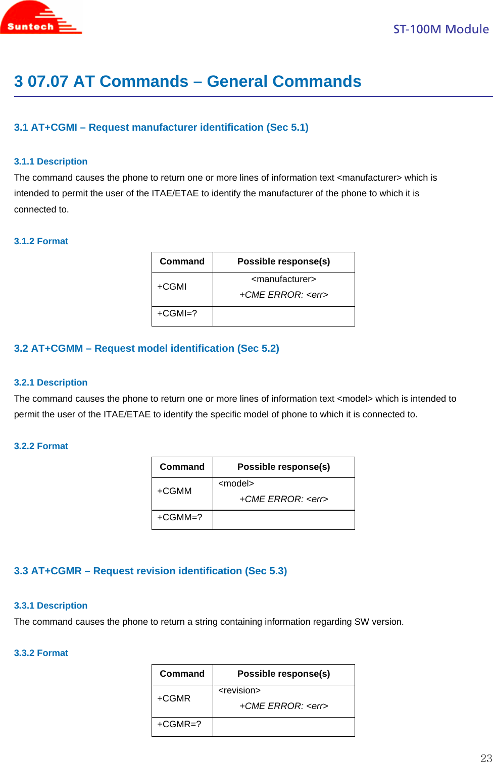
![ST-100M Module 243.4 AT+CGSN – Request product serial number identification (Sec 5.4) 3.4.1 Description Returns the IMEI number of the phone. 3.4.2 Format Command Possible response(s) +CGSN <serial number> <CR><LF> <IMEI> +CME ERROR: <err> +CGSN=? 3.5 AT+CSCS – Select TE character set (Sec 5.5) 3.5.1 Description Set command informs TA which character set <chset> is used by the TE. TA is then able to convert character strings correctly between TE and MT character sets. 3.5.2 Format Command Possible response(s) +CSCS=[<chset>] +CSCS? +CSCS: <chset> +CSCS=? +CSCS: (list of supported <chset>s) 3.5.3 Field "GSM" GSM 7 bit default alphabet (3GPP TS 23.038); this setting causes easily software flow control (XON/XOFF) problems "HEX" character strings consist only of hexadecimal numbers from 00 to FF; e.g. "032FE6" equals three 8-bit characters with decimal values 3, 47 and 230; no conversions to the original MT character set shall be done. "IRA" international reference alphabet (ITU-T T.50 [13]) "PCCP437" PC character set Code Page 437 "UCS2" 16-bit universal multiple-octet coded character set (ISO/IEC10646 [32]); UCS2 character strings are converted to hexadecimal numbers from 0000 to FFFF; e.g. "004100620063" equals three 16-bit characters with decimal values 65, 98 and 99 "8859-1" ISO 8859 Latin character set](https://usermanual.wiki/Suntech/ST-100M/User-Guide-946988-Page-24.png)
![ST-100M Module 253.6 AT+CIMI – Request international mobile subscriber identity (Sec 5.6)3.6.1 Description Execution command causes the TA to return <IMSI>, which is intended to permit the TE to identify the individual SIM which is attached to ME. Refer [1] 9.2 for possible <err> values. 3.6.2 Format Command Possible response(s) +CIMI <IMSI> +CME ERROR: <err> +CIMI=?](https://usermanual.wiki/Suntech/ST-100M/User-Guide-946988-Page-25.png)
![ST-100M Module 264 07.07 AT Commands – Call Control commands 4.1 AT+CMOD – Call mode (Sec 6.4) 4.1.1 Description Selects the call mode for future dialing commands or for the next answering command. 4.1.2 Format Command Possible response(s) +CMOD=[<mode>] +CMOD? +CMOD: <mode> +CMOD=? +CMOD: (list of supported <mode>s) 4.1.3 Field <mode>: 0 single mode 1 alternating voice/fax (teleservice 61) 2 alternating voice/data (bearer service 61) 3 voice followed by data (bearer service 81) 4.2 AT+CHUP – Hang up call (Sec 6.5) 4.2.1 Description Request to hang up the current GSM call. 4.2.2 Format Command Possible response(s) +CHUP +CHUP=? +CMOD: <mode> 4.3 AT+CBST – Select bearer service type (Sec 6.7) 4.3.1 Description Selects the bearer service <name> with the data rate <speed>, and the connection element <ce> to be used when data calls are made. Values may also be used during mobile-terminated data-call setup, especially in the case of single numbering-scheme calls.](https://usermanual.wiki/Suntech/ST-100M/User-Guide-946988-Page-26.png)
![ST-100M Module 274.3.2 Format Command Possible response(s) +CBST=[<speed>[,<name>[,<ce>]]] +CBST? +CBST: <speed>,<name>,<ce> +CBST? +CBST: (list of supported <speed>s),(list of supported <name>s),(list of supported <ce>s) 4.3.3 Field <speed>: 0 auto bauding (automatic selection of the speed; this setting is possible in case of 3.1 kHz modem and non-transparent service) 4 2400 bps (V.22bis) 5 2400 bps (V.26ter) 6 4800 bps (V.32) 7 9600 bps (V.32) 12 9600 bps (V.34) 14 14400 bps (V.34) 68 2400 bps (V.110 or X.31 flag stuffing) 70 4800 bps (V.110 or X.31 flag stuffing) 71 9600 bps (V.110 or X.31 flag stuffing) 75 14400 bps (V.110 or X.31 flag stuffing) [NOTE] when <speed> = 4,5,6,7,12,14 , line type = Analog when <speed> =68,70,71,75 , line type = ISDN <name>: 0 data circuit asynchronous (UDI or 3.1 kHz modem) <ce>: 0 transparent 1 non-transparent 2 both, transparent preferred 3 both, non-transparent preferred 4.4 AT+CRLP – Radio Link Protocol (Sec 6.8) 4.4.1 Description Sets the radio link protocol parameters.](https://usermanual.wiki/Suntech/ST-100M/User-Guide-946988-Page-27.png)
![ST-100M Module 284.4.2 Format Command Possible response(s) +CRLP=[<iws>[,<mws>[ ,<T1>[,<N2>[,<ver>[,< T4>]]]]]] +CRLP? +CRLP: <iws>,<mws>,<T1>,<N2>[,<ver1>[,<T4>]] [<CR><LF>+CRLP: <iws>,<mws>,<T1>,<N2>[,<ver2>[,<T4>]] [...]] +CRLP=? +CRLP: (list of supported <iws>s),(list of supported <mws>s), (list of supported <T1>s),(list of supported <N2>s)[,<ver1> [,(list of supported <T4>s)]] [<CR><LF>+CRLP: (list of supported <iws>s),(list of supported <mws>s),(list of supported <T1>s),(list of supported <N2>s) [,<ver1>[,(list of supported <T4>s)]] [...]] 4.4.3 Field <ver>, <verx>: RLP version number in integer format; only support version 0. <iws>, <mws>, <T1>, <N2>, <T4>: IWF to MS window size, MS to IWF window size, acknowledgement timer T1, retransmission attempts N2, re-sequencing period T4 in integer format. T1 and T4 are in units of 10 ms. <ver> and <T4> in set command are ignored. 4.5 AT+CR – Service reporting control (Sec 6.9) 4.5.1 Description Service reporting control. Set command controls whether or not intermediate result code +CR: <serv> is returned from the TA to the TE. If enabled, the intermediate result code is transmitted at the point during connect negotiation at which the TA has determined which speed and quality of service will be used, before any error control or data compression reports are transmitted, and before the intermediate result code CONNECT is transmitted. 4.5.2 Format Command Possible response(s) +CR=[<mode>] +CR? +CR: <mode> +CR=? +CR: (list of supported <mode>s)](https://usermanual.wiki/Suntech/ST-100M/User-Guide-946988-Page-28.png)
![ST-100M Module 294.5.3 Field <mode>: 0 disables reporting 1 enables reporting <serv>: ASYNC asynchronous transparent SYNC synchronous transparent REL ASYNC asynchronous non-transparent REL SYNC synchronous non-transparent 4.6 AT+CEER – Extended error report (Sec 6.10) 4.6.1 Description Execution command causes the TA to return one or more lines of information text <report>, which offer the user of the TA an extended report of the reason for - the failure in the last unsuccessful call setup (originating or answering) or in-call modification; - the last call release; 4.6.2 Format Command Possible response(s) +CEER +CEER: <cause>, <report> +CEER=? +CR: <mode> 4.6.3 Field <cause>: cause value listed in GSM 04.08 annex H. <report>: string type describes cause value. 4.7 AT+CRC – Cellular result code (Sec 6.11) 4.7.1 Description Set command controls whether or not the extended format of incoming call indication or GSM network request for PDP context activation is used. When enabled, an incoming call is indicated to the TE with unsolicited result code +CRING: <type> instead of the normal RING. 4.7.2 Format Command Possible response(s) +CRC=[<mode>] +CRC? +CRC: <mode> +CRC=? +CRC: (list of supported <mode>s)](https://usermanual.wiki/Suntech/ST-100M/User-Guide-946988-Page-29.png)
![ST-100M Module 304.7.3 Field <mode>: 0 disables extended format 1 enables extended format <type>: ASYNC asynchronous transparent SYNC synchronous transparent REL ASYNC asynchronous non-transparent REL SYNC synchronous non-transparent FAX facsimile (TS 62) VOICE normal voice (TS 11) VOICE/XXX voice followed by data (BS 81) (XXX is ASYNC, SYNC, REL ASYNC or REL SYNC) ALT VOICE/XXX alternating voice/data, voice first (BS 61) ALT XXX/VOICE alternating voice/data, data first (BS 61) ALT VOICE/FAX alternating voice/fax, voice first (TS 61) ALT FAX/VOICE alternating voice/fax, fax first (TS 61). 4.8 AT+CSNS – Single Numbering Scheme (Sec 6.19) 4.8.1 Description Set command selects the bearer or teleservice to be used when mobile terminated single numbering scheme call is established. Parameter values set with +CBST command shall be used when <mode> equals to a data service. 4.8.2 Format Command Possible response(s) +CSNS=[<mode>] +CSNS? +CSNS: <mode> +CSNS=? +CSNS: (list of supported <mode>s) 4.8.3 Field <mode>: 0 voice 1 alternating voice/fax, voice first (TS 61) 2 fax (TS 62) 3 alternating voice/data, voice first (BS 61) 4 data 5 alternating voice/fax, fax first (TS 61) 6 alternating voice/data, data first (BS 61)](https://usermanual.wiki/Suntech/ST-100M/User-Guide-946988-Page-30.png)
![ST-100M Module 317 voice followed by data (BS 81) 8 4.9 AT+CVHU – Voice Hangup Control (Sec 6.20) 4.9.1 Description Set command selects whether ATH or "drop DTR" shall cause a voice connection to be disconnected or not. By voice connection is also meant alternating mode calls that are currently in voice mode. 4.9.2 Format Command Possible response(s) +CVHU=[<mode>] +CVHU? +CVHU:<mode> +CVHU=? +CVHU:(list of supported <mode>s) 4.9.3 Field <mode>: 0 - "Drop DTR" ignored but OK response given. ATH disconnects. 4.10 AT+CSDF – Settings Date Format (Sec 6.22) 4.10.1 Description Set the date format of the date information presented to the user. 4.10.2 Format Command Possible response(s) +CSDF=[[<mode>] [,<auxmode>]] +CME ERROR: <err> +CSDF? +CSDF:<mode>[,<auxmode>] +CME ERROR: <err> +CSDF=? +CSDF:(list of supported <mode>s) [, (list of supported <auxmode>s)] +CME ERROR: <err> 4.10.3 Field <mode>: 1 DD-MMM-YYYY 8 DD/MM/YYYY 9 MM/DD/YYYY 10 YYYY/MM/DD 11 YYYY-MM-DD](https://usermanual.wiki/Suntech/ST-100M/User-Guide-946988-Page-31.png)
![ST-100M Module 3212 MMM DD,YYYY <auxmode>: 1 yy/MM/dd (default) 2 yyyy/MM/dd 4.11 AT+CSIL – Silence Command (Sec 6.23) 4.11.1 Description Enable/Disable the silent mode. 4.11.2 Format Command Possible response(s) +CSIL=<mode> +CME ERROR: <err> +CSIL? +CSIL:<mode> +CME ERROR: <err> +CSIL=? +CSIL:(list of supported <mode>s) +CME ERROR: <err> 4.11.3 Field <mode>: 0 Silent mode off 1 Silent mode on 4.12 AT+CSTF – Settings Time Format (Sec 6.24) 4.12.1 Description Set time format of the time information presented to the user. 4.12.2 Format Command Possible response(s) +CSTF=[<mode>] +CME ERROR: <err> +CSTF? +CSTF:<mode> +CME ERROR: <err> +CSTF=? +CSTF:(list of supported <mode>s) +CME ERROR: <err> 4.12.3 Field <mode>: 1 HH:MM (24 hour clock) 2 HH:MM a.m./p.m.](https://usermanual.wiki/Suntech/ST-100M/User-Guide-946988-Page-32.png)
![ST-100M Module 335 07.07 AT Commands –Network Service Related Commands 5.1 AT+CREG – Network Registration (Sec 7.2) 5.1.1 Description Set command controls the presentation of an unsolicited result code +CREG: <stat> when <n>=1 and there is a change in the MT network registration status, or code +CREG: <stat>[,<lac>,<ci>] when <n>=2 and there is a change of the network cell. Read command returns the status of result code presentation and an integer <stat> which shows whether the network has currently indicated the registration of the MT. Location information elements <lac> and <ci> are returned only when <n>=2 and MT is registered in the network. 5.1.2 Format Command Possible response(s) +CREG=[<n>] +CREG? +CREG: <n>,<stat>[,<lac>,<ci>] +CME ERROR: <err> +CREG=? +CREG: (list of supported <n>s) 5.1.3 Field <n>: 0 disable network registration unsolicited result code 1 enable network registration unsolicited result code +CREG: <stat> 2 enable network registration and location information unsolicited result code +CREG: <stat>[,<lac>,<ci>] <stat>: 0 not registered, MT is not currently searching a new operator to register to 1 registered, home network 2 not registered, but MT is currently searching a new operator to register to 3 registration denied 4 unknown 5 registered, roaming <lac>: string type; two byte location area code in hexadecimal format (e.g. "00C3" equals 195 in decimal) <ci>: string type; two byte cell ID in hexadecimal format](https://usermanual.wiki/Suntech/ST-100M/User-Guide-946988-Page-33.png)
![ST-100M Module 346 07.07 AT Commands –MT Control and Status Command 6.1 AT+CPAS – Phone activity status (Sec 8.1) 6.1.1 Description Returns the activity status <pas> of the ME. It can be used to interrogate the ME before requesting action from the phone. If the command is executed without the <mode> parameter, only <pas> values from 0 to 128 are returned. If the <mode> parameter is included in the execution command, <pas> values from 129 to 255 may also be returned. 6.1.2 Format Command Possible response(s) +CPAS +CPAS: <pas> +CME ERROR: <err> +CPAS=? +CPAS: (list of supported <pas>s) +CME ERROR: <err> 6.1.3 Field <pas>: 0 ready (MT allows commands from TA/TE) 1 unavailable (MT does not allow commands from TA/TE) 2 unknown (MT is not guaranteed to respond to instructions) 3 ringing (MT is ready for commands from TA/TE, but the ringer is active) 4 call in progress (MT is ready for commands from TA/TE, but a call is in progress) 5 asleep (MT is unable to process commands from TA/TE because it is in a low functionality state) 6.2 AT+CFUN – Set Phone Functionality (Sec 8.2) 6.2.1 Description We only support full functionality so far. AT+CFUN = 1, 1 can reset the target. 6.2.2 Format Command Possible response(s) +CFUN=[<fun>[,<rst>]] +CME ERROR: <err> +CFUN=? +CFUN: (list of supported <fun>s), (list of supported <rst>s) +CME ERROR: <err>](https://usermanual.wiki/Suntech/ST-100M/User-Guide-946988-Page-34.png)
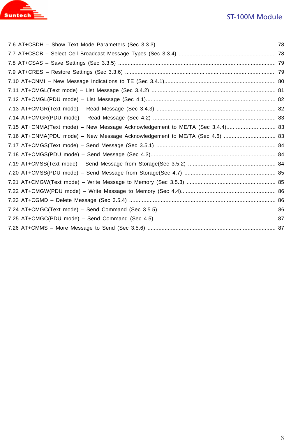
![ST-100M Module 356.2.3 Field <fun> : 1 full functionality <rst> : 0 do not reset the MT before setting it to <fun> power level 1 reset the MT before setting it to <fun> power level 6.3 AT+CPIN – Enter PIN (Sec 8.3) 6.3.1 Description Set command sends to the ME a password which is necessary before it can be operated (SIM PIN, SIM PUK, PH-SIM PIN, etc.). If the PIN is to be entered twice, the TA shall automatically repeat the PIN. If no PIN request is pending, no action is taken towards ME and an error message, +CME ERROR, is returned to TE. Refer [1] 9.2 for possible <err> values. If the PIN required is SIM PUK or SIM PUK2, the second pin is required. This second pin, <newpin>, is used to replace the old pin in the SIM. 6.3.2 Format Command Possible response(s) +CPIN=<pin>[,<newpin>] +CME ERROR: <err> +CPIN? +CPIN: <code> +CME ERROR: <err> +CPIN=? 6.3.3 Field <pin>, <newpin>: string type values <code> values reserved by the present document: READY MT is not pending for any password SIM PIN MT is waiting SIM PIN to be given SIM PUK MT is waiting SIM PUK to be given PH-SIM PIN MT is waiting phone to SIM card password to be given PH-FSIM PIN MT is waiting phone-to-very first SIM card password to be given PH-FSIM PUK MT is waiting phone-to-very first SIM card unblocking password to be given SIM PIN2 MT is waiting SIM PIN2 to be given SIM PUK2 MT is waiting SIM PUK2 to be given PH-NET PIN MT is waiting network personalization password to be given PH-NET PUK MT is waiting network personalization unblocking password to be given PH-NETSUB PIN MT is waiting network subset personalization password to be given PH-NETSUB PUK MT is waiting network subset personalization unblocking password to be given PH-SP PIN MT is waiting service provider personalization password to be given PH-SP PUK MT is waiting service provider personalization unblocking password to be given PH-CORP PIN MT is waiting corporate personalization password to be given PH-CORP PUK MT is waiting corporate personalization unblocking password to be given PHONE LOCK MT is waiting phone lock code](https://usermanual.wiki/Suntech/ST-100M/User-Guide-946988-Page-35.png)
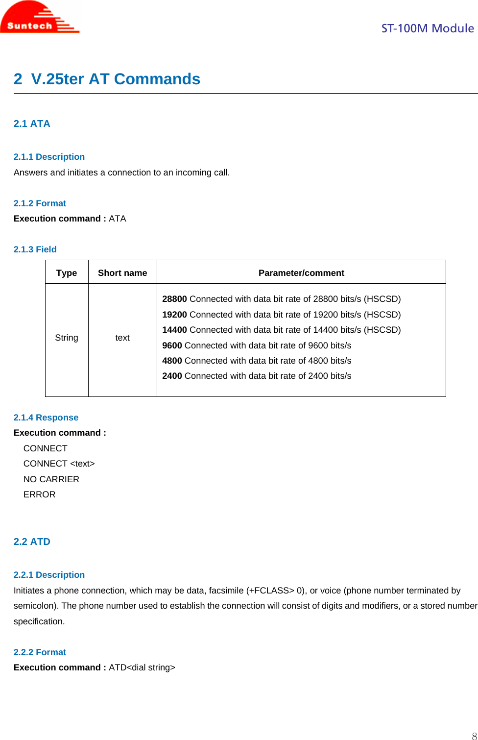
![ST-100M Module 370...7 as RXQUAL values in the table in TS 45.008 [20] subclause 8.2.4 not known or not detectable](https://usermanual.wiki/Suntech/ST-100M/User-Guide-946988-Page-37.png)
![ST-100M Module 387 07.05 SMS AT Commands Please refer to 27.005 Sec 3.1 Parameter Definition to see more details of the parameter fields in each command. 7.1 AT+CSMS – Select Message Service (Sec 3.2.1) 7.1.1 Description Selects the message service and returns the type of messages supported by the ME. If chosen service is not supported by the ME (but supported by the TA), +CME ERROR is returned. 7.1.2 Format Command Possible response(s) +CSMS=<service> +CSMS: <mt>,<mo>,<bm> +CMS ERROR: <err> +CSMS? +CSMS: <service>,<mt>,<mo>,<bm> +CSMS=? +CSMS: (list of supported <service>s) 7.1.3 Field <service>: 0 3GPP TS 23.040 [3] and 3GPP TS 23.041 [4] 1 3GPP TS 23.040 [3] and 3GPP TS 23.041 [4] the requirement of <service> setting 1 is mentioned under corresponding command descriptions) <mt>, <mo>, <bm>: 0 type not supported 1 type supported 7.2 AT+CPMS – Preferred Message Storage (Sec 3.2.2) 7.2.1 Description Selects memory storage spaces to be used for reading, writing, etc. If chosen storage is not appropriate for the ME (but is supported by the TA), +CME ERROR is returned. 7.2.2 Format Command Possible response(s) +CPMS=<mem1> +CPMS: <used1>,<total1>,<used2>,<total2>,<used3>,<total3> +CMS ERROR: <err> +CPMS? +CPMS: <mem1>,<used1>,<total1>,<mem2>,<used2>,<total2>,](https://usermanual.wiki/Suntech/ST-100M/User-Guide-946988-Page-38.png)
![ST-100M Module 39<mem3>,<used3>,<total3> +CMS ERROR: <err> +CPMS=? +CPMS: (list of supported <mem1>s),(list of supported <mem2>s), (list of supported <mem3>s) 7.3 AT+CMGF – Message Format (Sec 3.2.3) 7.3.1 Description Sets the input and output format to be used by the TA. 7.3.2 Format Command Possible response(s) +CMGF=[<mode>] +CMGF? +CMGF: <mode> +CMGF=? +CMGF: (list of supported <mode>s) 7.3.3 Field <mode>: 0 PDU mode (default when implemented) 1 text mode 7.4 AT+CSCA – Service Center Address (Sec 3.3.1) 7.4.1 Description Updates the SMCS address, through which mobile-originated SMSs are transmitted. In text mode, the setting is used by send (AT+CMGS) and write (AT+CMGW) commands. In PDU mode, the setting is used by the same commands, but only when the length of the SMCS address (coded into <pdu> parameter) equals zero. 7.4.2 Format Command Possible response(s) +CSCA=<sca>[,<tosca>] +CSCA? +CSCA: <sca>,<tosca> +CSCA=? +CMGF: (list of supported <mode>s)](https://usermanual.wiki/Suntech/ST-100M/User-Guide-946988-Page-39.png)
![ST-100M Module 407.5 AT+CSMP – Set Text Mode Parameters (Sec 3.3.2) 7.5.1 Description Setting Text Mode Parameters. Set command is used to select values for additional parameters needed when SM is sent to the network or placed in a storage when text format message mode is selected. It is possible to set the validity period starting from when the SM is received by the SMSC (<vp> is in range 0... 255) or define the absolute time of the validity period termination (<vp> is a string). The format of <vp> is given by <fo>. 7.5.2 Format Command Possible response(s) +CSMP=[<fo>[,<vp>[,<pid>[,<dcs>]]]] +CSMP? +CSMP: <fo>,<vp>,<pid>,<dcs> +CSMP=? +CMGF: (list of supported <mode>s) 7.6 AT+CSDH – Show Text Mode Parameters (Sec 3.3.3) 7.6.1 Description Set command controls whether detailed header information is shown in text mode result codes. Test command returns supported values as a compound value. 7.6.2 Format Command Possible response(s) +CSDH=[<show>] +CSDH? +CSDH: <show> +CSDH=? +CSDH: (list of supported <show>s) 7.7 AT+CSCB – Select Cell Broadcast Message Types (Sec 3.3.4) 7.7.1 Description Selects which types of CBMs are to be received by the ME. 7.7.2 Format Command Possible response(s) +CSCB=[<mode>[,<mids>]] +CSCB? +CSCB: <mode>,<mids> +CSCB=? +CSCB: (list of supported <mode>s)](https://usermanual.wiki/Suntech/ST-100M/User-Guide-946988-Page-40.png)
![ST-100M Module 417.7.3 Field <mode>: 0 message types specified in <mids> and <dcss> are accepted <mids>: We support 10 message identifiers at most. string type: all different possible combinations of CBM message identifiers (refer <mid>) (default is empty string); e.g. "0,1,5,320-478,922" 7.8 AT+CSAS – Save Settings (Sec 3.3.5) 7.8.1 Description Execution command saves active message service settings to a non-volatile memory. Settings specified in commands Service Centre Address +CSCA, Set Message Parameters +CSMP and Select Cell Broadcast Message Types +CSCB (if implemented) are saved. Certain settings may not be supported by the storage (e.g. (U)SIM SMS parameters) and therefore can not be saved. 7.8.2 Format Command Possible response(s) +CSAS[=<profile>] +CMS ERROR: <err> +CSAS=? +CSAS: (list of supported <profile>s) 7.8.3 Field <profile>: 0...255 manufacturer specific profile number where settings are to be stored 7.9 AT+CRES – Restore Settings (Sec 3.3.6) 7.9.1 Description Execution command restores message service settings from non-volatile memory to active memory. A TA can contain several profiles of settings. Settings specified in commands Service Centre Address +CSCA, Set Message Parameters +CSMP and Select Cell Broadcast Message Types +CSCB (if implemented) are restored. Certain settings may not be supported by the storage (e.g. (U)SIM SMS parameters) and therefore can not be restored. 7.9.2 Format Command Possible response(s) +CRES[=<profile>] +CMS ERROR: <err> +CRES=? +CRES: (list of supported <profile>s)](https://usermanual.wiki/Suntech/ST-100M/User-Guide-946988-Page-41.png)
![ST-100M Module 427.9.3 Field <profile>: 0...255 manufacturer specific profile number where settings are to be stored 7.10 AT+CNMI – New Message Indications to TE (Sec 3.4.1) 7.10.1 Description Selects the procedure how the reception of new messages from the network is indicated to the TE when TE is active (DTR signal is ON). IF TE is inactive (DTR signal OFF), message reception is carried out as specified in GSM 03.38. This command enables the unsolicited result codes +CMT, +CMTI, +CBM, and +CDS. (Please refer to 07.07 for more detail) 7.10.2 Format Command Possible response(s) +CNMI=[<mode>[,<mt>[,<bm>[,<ds> ,<bfr>]]]]] +CMS ERROR: <err> +CNMI? +CNMI: <mode>,<mt>,<bm>,<ds>,<bfr> +CNMI=? +CNMI: (list of supported <mode>s),(list of supported <mt>s),(list of supported <bm>s),(list of supported <ds>s),(list of supported <bfr>s) 7.10.3 Field <mode> 0 disable unsolicited result code 1 Discard indication and reject new received message unsolicited result codes when TA-TE link is reserved (e.g. in on-line data mode). Otherwise forward them directly to the TE. <mt> 0 No SMS-DELIVER indications are routed to the TE. 1 If SMS-DELIVER is stored into ME/TA, indication of the memory location is routed to the TE using unsolicited result code: +CMTI: <mem>,<index> 2 SMS-DELIVERs (except class 2 messages and messages in the message waiting indication group (store message)) are routed directly to the TE using unsolicited result code: +CMT: [<alpha>],<length><CR><LF><pdu> (PDU mode enabled); or +CMT: <oa>, [<alpha>],<scts>[,<tooa>,<fo>,<pid>,<dcs>,<sca>,<tosca>, <length>] <CR><LF> <data> (text mode enabled; about parameters in italics, refer command Show Text Mode Parameters +CSDH) 3 Class 3 SMS-DELIVERs are routed directly to TE using unsolicited result codes defined in <mt>=2. Messages of other data coding schemes result in indication as defined in <mt>=1. <bm>](https://usermanual.wiki/Suntech/ST-100M/User-Guide-946988-Page-42.png)
![ST-100M Module 430 No CBM indications are routed to the TE. 1 If CBM is stored into ME/TA, indication of the memory location is routed to the TE using unsolicited result code: +CBMI: <mem>,<index> 2 New CBMs are routed directly to the TE using unsolicited result code: +CBM: <length><CR><LF><pdu> (PDU mode enabled); or +CBM: <sn>,<mid>,<dcs>,<page>,<pages><CR><LF><data> (text mode enabled) If ME supports data coding groups which define special routing also for messages other than class 3 (e.g. (U)SIM specific messages), ME may choose not to route messages of such data coding schemes into TE (indication of a stored CBM may be given as defined in <bm>=1). 3 Class 3 CBMs are routed directly to TE using unsolicited result codes defined in <bm>=2. If CBM storage is supported, messages of other classes result in indication as defined in <bm>=1. <ds>: 0 No SMS-STATUS-REPORTs are routed to the TE. 1 SMS-STATUS-REPORTs are routed to the TE using unsolicited result code: +CDS: <length><CR><LF><pdu> (PDU mode enabled); or +CDS: <fo>,<mr>,[<ra>],[<tora>],<scts>,<dt>,<st> (text mode enabled) 2 If SMS-STATUS-REPORT is stored into ME/TA, indication of the memory location is routed to the TE using unsolicited result code: +CDSI: <mem>,<index> <bfr>: 1 TA buffer of unsolicited result codes defined within this command is cleared when <mode> 1...3 is entered. 7.11 AT+CMGL(Text mode) – List Message (Sec 3.4.2) 7.11.1 Description Returns messages with status value <stat> from returned message in preferred storage to the TE. 7.11.2 Format Command Possible response(s) +CMGL[=<stat>] if text mode (+CMGF=1), command successful and SMS-SUBMITs and/or SMSDELIVERs: +CMGL: <index>,<stat>,<oa/da>,[<alpha>],[<scts>][,<tooa/toda>, <length>]<CR><LF><data>[<CR><LF> +CMGL: <index>,<stat>,<da/oa>,[<alpha>],[<scts>][,<tooa/toda>, <length>]<CR><LF><data>[...]] if text mode (+CMGF=1), command successful and SMS-STATUS-REPORTs: +CMGL: <index>,<stat>,<fo>,<mr>,[<ra>],[<tora>],<scts>,<dt>,<st> [<CR><LF>](https://usermanual.wiki/Suntech/ST-100M/User-Guide-946988-Page-43.png)
![ST-100M Module 44+CMGL: <index>,<stat>,<fo>,<mr>,[<ra>],[<tora>],<scts>,<dt>,<st> [...]] if text mode (+CMGF=1), command successful and SMS-COMMANDs: +CMGL: <index>,<stat>,<fo>,<ct>[<CR><LF> +CMGL: <index>,<stat>,<fo>,<ct>[...]] if text mode (+CMGF=1), command successful and CBM storage: +CMGL: <index>,<stat>,<sn>,<mid>,<page>,<pages> <CR><LF><data>[<CR><LF> +CMGL: <index>,<stat>,<sn>,<mid>,<page>,<pages> <CR><LF><data>[...]] otherwise: +CMS ERROR: <err> +CMGL=? +CMGL: (list of supported <stat>s) 7.12 AT+CMGL(PDU mode) – List Message (Sec 4.1) 7.12.1 Description Returns messages with status value <stat> from returned message in preferred storage to the TE. 7.12.2 Format Command Possible response(s) +CMGL[=<stat>] if PDU mode (+CMGF=0) and command successful: +CMGL: <index>,<stat>,[<alpha>],<length><CR><LF><pdu> [<CR><LF>+CMGL:<index>,<stat>,[<alpha>],<length><CR><LF><pdu> [...]] otherwise: +CMS ERROR: <err> +CMGL=? +CMGL: (list of supported <stat>s) 7.13 AT+CMGR(Text mode) – Read Message (Sec 3.4.3) 7.13.1 Description Returns messages with location value <index> from preferred message storage <mem1> to the TE. If the status of the message is .received unread., the status in the storage changes to .received read.. If reading fails, +CMS ERROR is returned.](https://usermanual.wiki/Suntech/ST-100M/User-Guide-946988-Page-44.png)
![ST-100M Module 457.13.2 Format Command Possible response(s) +CMGR=<index> if text mode (+CMGF=1), command successful and SMS-DELIVER: +CMGR: <stat>,<oa>,[<alpha>],<scts>[,<tooa>,<fo>,<pid>,<dcs>, <sca>,<tosca>,<length>]<CR><LF><data> if text mode (+CMGF=1), command successful and SMS-SUBMIT: +CMGR: <stat>,<da>,[<alpha>][,<toda>,<fo>,<pid>,<dcs>,[<vp>], <sca>,<tosca>,<length>]<CR><LF><data> if text mode (+CMGF=1), command successful and SMS-STATUS-REPORT: +CMGR: <stat>,<fo>,<mr>,[<ra>],[<tora>],<scts>,<dt>,<st> if text mode (+CMGF=1), command successful and SMS-COMMAND:+CMGR: <stat>,<fo>,<ct>[,<pid>,[<mn>],[<da>],[<toda>],<length> <CR><LF><cdata>] if text mode (+CMGF=1), command successful and CBM storage: +CMGR: <stat>,<sn>,<mid>,<dcs>,<page>,<pages><CR><LF><data> otherwise: +CMS ERROR: <err> +CMGR=? 7.14 AT+CMGR(PDU mode) – Read Message (Sec 4.2) 7.14.1 Description Returns messages with location value <index> from preferred message storage <mem1> to the TE. If the status of the message is .received unread., the status in the storage changes to .received read.. If reading fails, +CMS ERROR is returned. 7.14.2 Format Command Possible response(s) +CMGR=<index> if PDU mode (+CMGF=0) and command successful: +CMGR: <stat>,[<alpha>],<length><CR><LF><pdu> otherwise: +CMS ERROR: <err> +CMGR=?](https://usermanual.wiki/Suntech/ST-100M/User-Guide-946988-Page-45.png)
![ST-100M Module 467.15 AT+CNMA(Text mode) – New Message Acknowledgement to ME/TA (Sec 3.4.4) 7.15.1 Description Execution command confirms correct reception of a new message (SMS-DELIVER or SMS-STATUSREPORT) which is routed directly to the TE. This acknowledgement command (causing ME to send RP-ACK to the network) shall be used when +CSMS parameter <service> equals 1. 7.15.2 Format Command Possible response(s) if text mode (+CMGF=1): +CNMA +CMS ERROR: <err> +CNMA=? 7.16 AT+CNMA(PDU mode) – New Message Acknowledgement to ME/TA (Sec 4.6) 7.16.1 Description Execution command confirms correct reception of a new message (SMS-DELIVER or SMS-STATUSREPORT) which is routed directly to the TE This acknowledgement command (causing ME to send RP-ACK to the network) shall be used when +CSMS parameter <service> equals 1. 7.16.2 Format Command Possible response(s) if PDU mode (+CMGF=0): +CNMA[=<n>[,<length>[<CR> PDU is given<ctrl-Z/ESC>]]] +CMS ERROR: <err> +CNMA=? if PDU mode (+CMGF=0): +CNMA: (list of supported <n>s) 7.17 AT+CMGS(Text mode) – Send Message (Sec 3.5.1) 7.17.1 Description Execution command sends message from a TE to the network (SMS-SUBMIT). Message reference value <mr> is returned to the TE on successful message delivery. 7.17.2 Format Command Possible response(s) if text mode (+CMGF=1): +CMGS=<da>[,<toda>]<CR> if text mode (+CMGF=1) and sending successful: +CMGS: <mr>[,<scts>]](https://usermanual.wiki/Suntech/ST-100M/User-Guide-946988-Page-46.png)
![ST-100M Module 47text is entered<ctrl-Z/ESC> if sending fails: +CMS ERROR: <err> +CMGS=? 7.18 AT+CMGS(PDU mode) – Send Message (Sec 4.3) 7.18.1 Description Execution command sends message from a TE to the network (SMS-SUBMIT). Message reference value <mr> is returned to the TE on successful message delivery. 7.18.2 Format Command Possible response(s) if PDU mode (+CMGF=0): +CMGS=<length><CR> PDU is given<ctrl-Z/ESC> if PDU mode (+CMGF=0) and sending successful: +CMGS: <mr>[,<ackpdu>] if sending fails: +CMS ERROR: <err> +CMGS=? 7.19 AT+CMSS(Text mode) – Send Message from Storage(Sec 3.5.2) 7.19.1 Description Execution command sends message with location value <index> from preferred message storage <mem2> to the network (SMS-SUBMIT or SMS-COMMAND). If new recipient address <da> is given for SMS-SUBMIT, it shall be used instead of the one stored with the message. Reference value <mr> is returned to the TE on successful message delivery. 7.19.2 Format Command Possible response(s) +CMSS=<index>[,<da>[,<toda>]] if text mode (+CMGF=1) and sending successful: +CMSS: <mr>[,<scts>] if sending fails: +CMS ERROR: <err> +CMSS=?](https://usermanual.wiki/Suntech/ST-100M/User-Guide-946988-Page-47.png)
![ST-100M Module 487.20 AT+CMSS(PDU mode) – Send Message from Storage(Sec 4.7) 7.20.1 Description Execution command sends message with location value <index> from message storage <mem2> to the network (SMS-SUBMIT or SMS-COMMAND). If new recipient address <da> is given for SMS-SUBMIT, it shall be used instead of the one stored with the message. Reference value <mr> is returned to the TE on successful message delivery. 7.20.2 Format Command Possible response(s) +CMSS=<index>[,<da>[,<toda>]] if PDU mode (+CMGF=0) and sending successful: +CMSS: <mr>[,<ackpdu>] if sending fails: +CMS ERROR: <err> +CMSS=? 7.21 AT+CMGW(Text mode) – Write Message to Memory (Sec 3.5.3) 7.21.1 Description Execution command stores a message to memory storage <mem2>. Memory location <index> of the stored message is returned. By default message status will be set to 'stored unsent', but parameter <stat> allows also other status values to be given, support ‘stored unsent’ and “stored sent” 7.21.2 Format Command Possible response(s) if text mode (+CMGF=1): +CMGW[=<oa/da>[,<tooa/toda>[,<stat>]]]<CR>text is entered<ctrl-Z/ESC> +CMGW: <index> +CMS ERROR: <err> +CMGW=? 7.22 AT+CMGW(PDU mode) – Write Message to Memory (Sec 4.4) 7.22.1 Description Execution command stores a message to memory storage <mem2>. Memory location <index> of the stored message is returned. By default message status will be set to 'stored unsent', but parameter <stat> allows also other status values to be given, support ‘stored unsent’ and “stored sent”](https://usermanual.wiki/Suntech/ST-100M/User-Guide-946988-Page-48.png)
![ST-100M Module 497.22.2 Format Command Possible response(s) if PDU mode (+CMGF=0): +CMGW=<length>[,<stat>]<CR>PDU is given <ctrl-Z/ESC> +CMGW: <index> +CMS ERROR: <err> +CMGW=? 7.23 AT+CGMD – Delete Message (Sec 3.5.4) 7.23.1 Description Deletes message from preferred message <mem1> (see AT+CPMS) storage location <index>. If deletion fails, +CMS ERROR is returned. 7.23.2 Format Command Possible response(s) +CMGD=<index>[,<delflag>] +CMS ERROR: <err> +CMGD=? +CMGD: (list of supported <index>s)[,(list of supported <delflag>s)] 7.23.3 Field <delflag>: an integer indicating multiple message deletion request as follows: 0 (or omitted) Delete the message specified in <index> 1 Delete all read messages from preferred message storage, leaving unread messages and stored mobile originated messages (whether sent or not) untouched 2 Delete all read messages from preferred message storage and sent mobile originated messages, leaving unread messages and unsent mobile originated messages untouched 3 Delete all read messages from preferred message storage, sent and unsent mobile originated messages leaving unread messages untouched. 4 Delete all messages from preferred message storage including unread messages. 7.24 AT+CMGC(Text mode) – Send Command (Sec 3.5.5) 7.24.1 Description Execution command sends a command message from a TE to the network (SMS-COMMAND).](https://usermanual.wiki/Suntech/ST-100M/User-Guide-946988-Page-49.png)
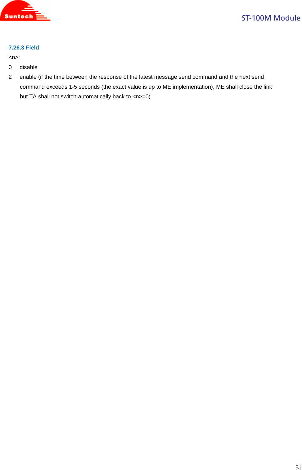
![ST-100M Module 507.24.2 Format Command Possible response(s) if text mode (+CMGF=1): +CMGC=<fo>,<ct>[,<pid>[,<mn>[,<da>[,<toda>]]]]<CR> text is entered<ctrl-Z/ESC> if text mode (+CMGF=1) and sending successful: +CMGC: <mr>[,<scts>] if sending fails: +CMS ERROR: <err> +CMGC=? 7.25 AT+CMGC(PDU mode) – Send Command (Sec 4.5) 7.25.1 Description Execution command sends a command message from a TE to the network (SMS-COMMAND). 7.25.2 Format Command Possible response(s) if PDU mode (+CMGF=0): +CMGC=<length><CR> PDU is given<ctrl-Z/ESC> if PDU mode (+CMGF=0) and sending successful: +CMGC: <mr>[,<ackpdu>] if sending fails: +CMS ERROR: <err> +CMGC=? 7.26 AT+CMMS – More Message to Send (Sec 3.5.6) 7.26.1 Description Set command controls the continuity of SMS relay protocol link. When feature is enabled (and supported by network) multiple messages can be sent much faster as link is kept open. Test command returns supported values as a compound value. 7.26.2 Format Command Possible response(s) +CMMS=[<n>] if PDU mode (+CMGF=0) and sending successful: +CMGC: <mr>[,<ackpdu>] if sending fails: +CMS ERROR: <err> +CMMS? +CMMS: <n> +CMMS=? +CMMS: (list of supported <n>s)](https://usermanual.wiki/Suntech/ST-100M/User-Guide-946988-Page-50.png)