Suntech ST210 Quad band GSM/GPRS Vehicle Tracker User Manual
Suntech International Ltd. Quad band GSM/GPRS Vehicle Tracker
UserManual.wiki
>
Suntech
>
ST210 User Manual
User manual
Navigation menu
Upload a User Manual
Namespaces
Wiki Guide
HTML
PDF
Info
Views
User Manual
Discussion / Help
Navigation
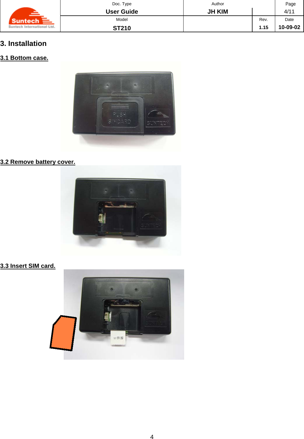
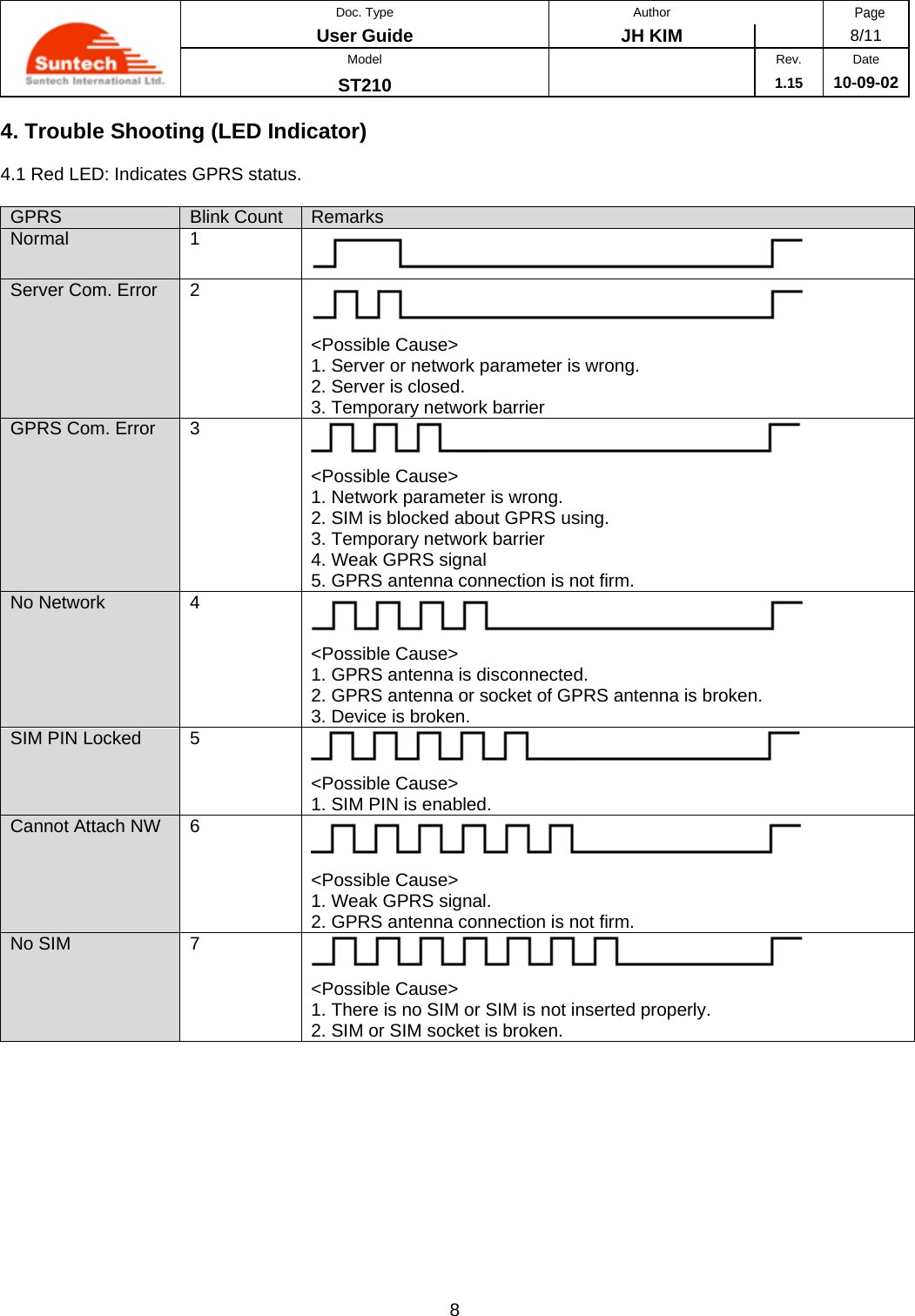
![Doc. Type Author Page User Guide JH KIM 1/11 Model Rev. Date ST210 1.15 10-09-02 1 1. Introduction This document describes Configuration, Parameter Setting and Installation Procedure of ST210 (including back-up battery). 2. Parameter Setting via SMS For reporting GPS position, the device should be set with adjustable parameters before installation. When SMS for setting is sent, the device replies response to predefined server though GPRS and sets corresponding parameters. Configuration of SMS message is as below. Each field is distinguished by ‘;’ in SMS message, and device ID means last 6 digits of IEMI number without checksum. 2.1 Network Parameter Message Field Definitions Unit Remark HDR “SA200NTW” Command type DEV_ID 6 char. Device ID VER “02” Protocol Version AUTH ‘0’ /‘1’/’A’ GPRS authentication 0 : Disable 1 : Enable A : Automatic GPRS set. In this case, parameters in APN, USER_ID and USER_PWD field should be empty. APN String Access Point Name USER_ID String ID for GPRS Access USER_PWD String Password for GPRS Access SEVER_IP String Server IP Address SEVER_PORT String Server Port B_SEVER_IP String Backup Server IP Address B_SEVER_PORT String Backup Server Port SMS_NO String Phone number what the device sends SMS report to. This can be used for backup in the area that f GPRS condition is not good. Or, it can be used main report method when IP and Port are empty. For no use, it should be empty. PIN_NO String PIN Number to release PIN lock if it is enabled <example 1> [command] SA200NTW;850000;02;0;internet;;;111.111.111.111;8600;;;; [response] SA200NTW;Res;850000;010;0;internet;;; 111.111.111.111;8600;;;; <example 2> SA200NTW;850000;02;A;;;;111.111.111.111;8600;;;; SA200NTW;Res;850000;010;A1;tim.br;tim;tim; 111.111.111.111;8600;;;; <notes> ** If network does not require User ID and Password, these fields should be empty.](https://usermanual.wiki/Suntech/ST210/User-Guide-1340612-Page-3.png)
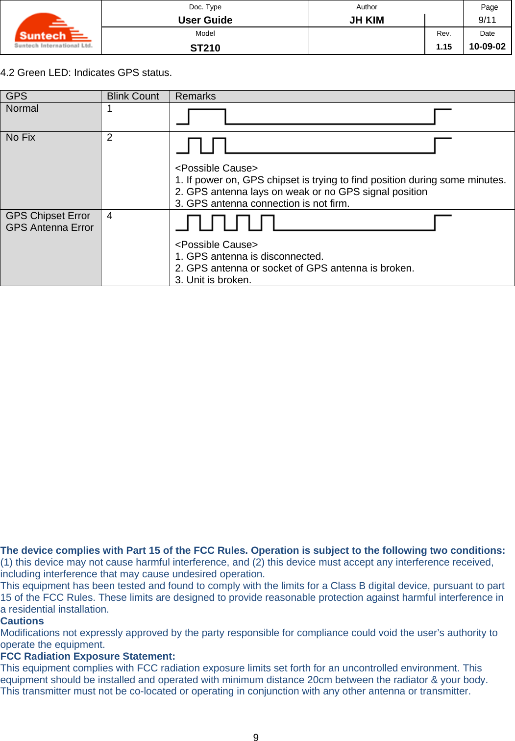
![Doc. Type Author Page User Guide JH KIM 2/11 Model Rev. Date ST210 1.15 10-09-02 2 2.2 Report Parameter Setting Field Definitions Unit Remark HDR “SA200RPT” Command type DEV_ID 6 char. Device ID VER “02” Protocol Version T1 String Sec Interval for sending status report in parking mode Range : 0 ~ 86400 If 0, report in parking will be sent only one time when vehicle starts parking. T2 String Sec Interval for sending status report in driving mode Range : 0 ~ 60000 If 0, report in driving will be sent only one time when vehicle starts driving. T3 String Sec Interval for sending status report in emergency mode Range : 0 ~ 9999 If 0, emergency report will be sent only one time when emergency state occurs. A1 String Number of attempts for emergency report until the device gets acknowledge from server If 0, no emergency report will be sent. SND_DIST String Meter Distance interval for sending status report. Range : 0 ~ 60000 (60km) If 0, status report related on moving distance is disabled. If not 0, stats report is send when traveled distance reaches predefined SND_DIST. T4 String Sec Interval for sending keep alive string SMS_T1 String Min Interval for sending status report in parking mode SMS_T2 String Min Interval for sending status report in driving mode SMS_PACK_NO String Report No in one SMS message <example> [command] SA200RPT;850000;02;180;120;60;3;0;0;0;0;0 [response] SA200RPT;Res;850000;010;180;120;60;3;0;0;0;0;0 2.3 Activate Output1 Field Definitions Unit Remark CMD_ID “Enable1” Enable Output1 <example> [command] SA200CMD;850000;02;Enable1 [response] SA200CMD;Res;850000;010;Enable1 <notes> ** Output1 line goes to active status.](https://usermanual.wiki/Suntech/ST210/User-Guide-1340612-Page-4.png)
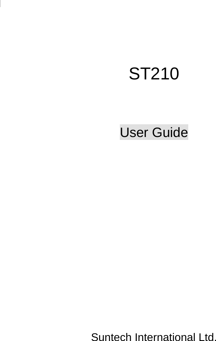
![Doc. Type Author Page User Guide JH KIM 3/11 Model Rev. Date ST210 1.15 10-09-02 3 2.4 Deactivate Output1 Field Definitions Unit Remark CMD_ID “Disable1” Disable Output1 <example> [command] SA200CMD;850000;02;Disable1 [response] SA200CMD;Res;850000;010;Disable1 <notes> ** Output1 line goes to inactive status. 2.5 Activate Output2 Field Definitions Unit Remark CMD_ID “Enable2” Enable Output2 <example> [command] SA200CMD;850000;02;Enable2 [response] SA200CMD;Res;850000;010;Enable2 <notes> ** Output2 line goes to active status. ** If OUT2 set to immobilizer, output2 line goes to active status gradually with pulse in driving mode. ** If OUT2 set to pulse type, output2 line generates pulse and returns inactive state after pulsing out automatically. 2.6 Deactivate Output2 Field Definitions Unit Remark CMD_ID “ReqIMSI” Request IMSI (unique SIM ID) If received, device sends IMSI of using SIM. <example> [command] SA200CMD;850000;02;ReqIMSI [response] SA200CMD;Res;850000;010;ReqIMSI;724031111553779](https://usermanual.wiki/Suntech/ST210/User-Guide-1340612-Page-5.png)