Suntech ST215 Quad band GSM and GPRS Vehicle Tracker User Manual
Suntech International Ltd. Quad band GSM and GPRS Vehicle Tracker
Suntech >
User manual

ST215
User Manual
Suntech International Ltd.
ST215 User Manual
ST215 Installation Guide
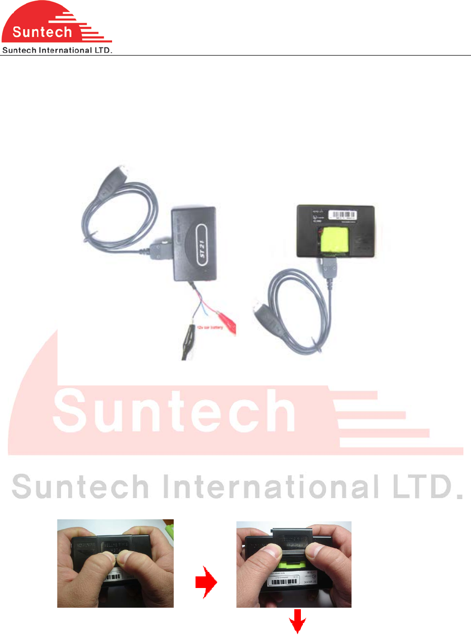
1. Configure ST 215 in the Lab by using Setting Tool.
Setting MUST be done with back up battery or external power. (12V)
For the details of configuration, refer to the other document.
2. Decide the location of ST215 and GPS Antenna, and check the cable ways.
Check whether the location of ST 210 is far away from other electric equipments.
GPS Antenna must have a sky-view and must be far away from other antenna.
3. Insert SIM card ( Can be done at the time of configuration)
Steps :
1. Open the battery cover, pick out the battery pack.
2
ST215 User Manual
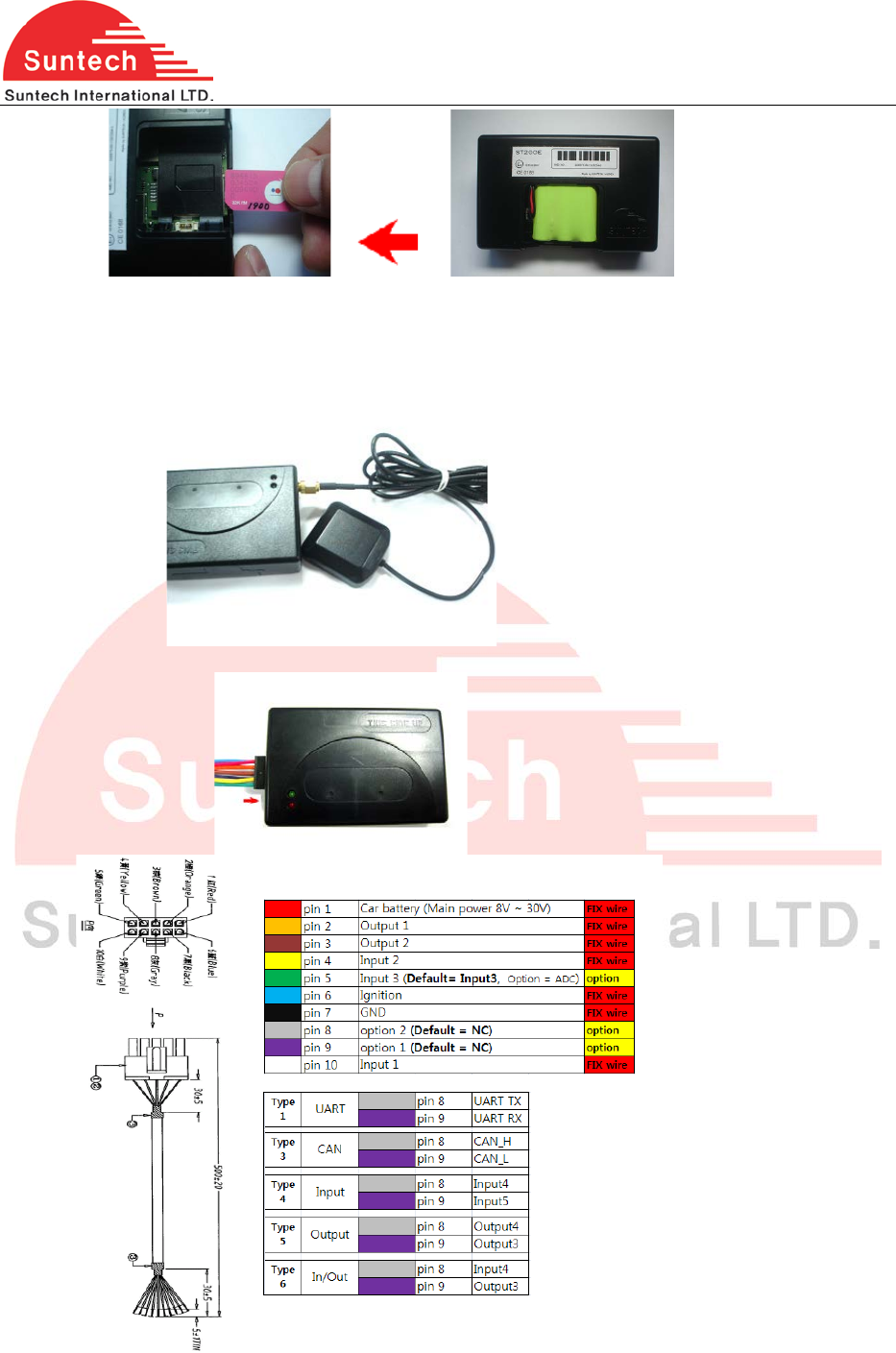
2. Insert the SIM card into the holder in the direction as shown above.
*Caution: when inserting, make sure that the unit is in the disconnected from main power.
4. Connect GPS Antenna
For avoiding ESD, installer must wear gloves
5. Connect Event Lines with relevant lines of vehicle.
Event Cable Description
3
ST215 User Manual
‘red’ line of Event cable
- Connect the red line to 12 VDC /24 VDC Constant power of vehicle
‘black’ line of Event cable
- Connect the black line to Ground of vehicle
‘blue’ line of Event cable
- Connect the blue line to an ignition wire of vehicle
Caution : Never connect the red & blue lines together to a constant power source
“Yellow , green, white” lines of Event cable
- For digital input lines
*Green line is use for digital input or ADC input according to your order option.
- For ADC Input
The voltage range of ADC input is from DC 0.5 to 30V
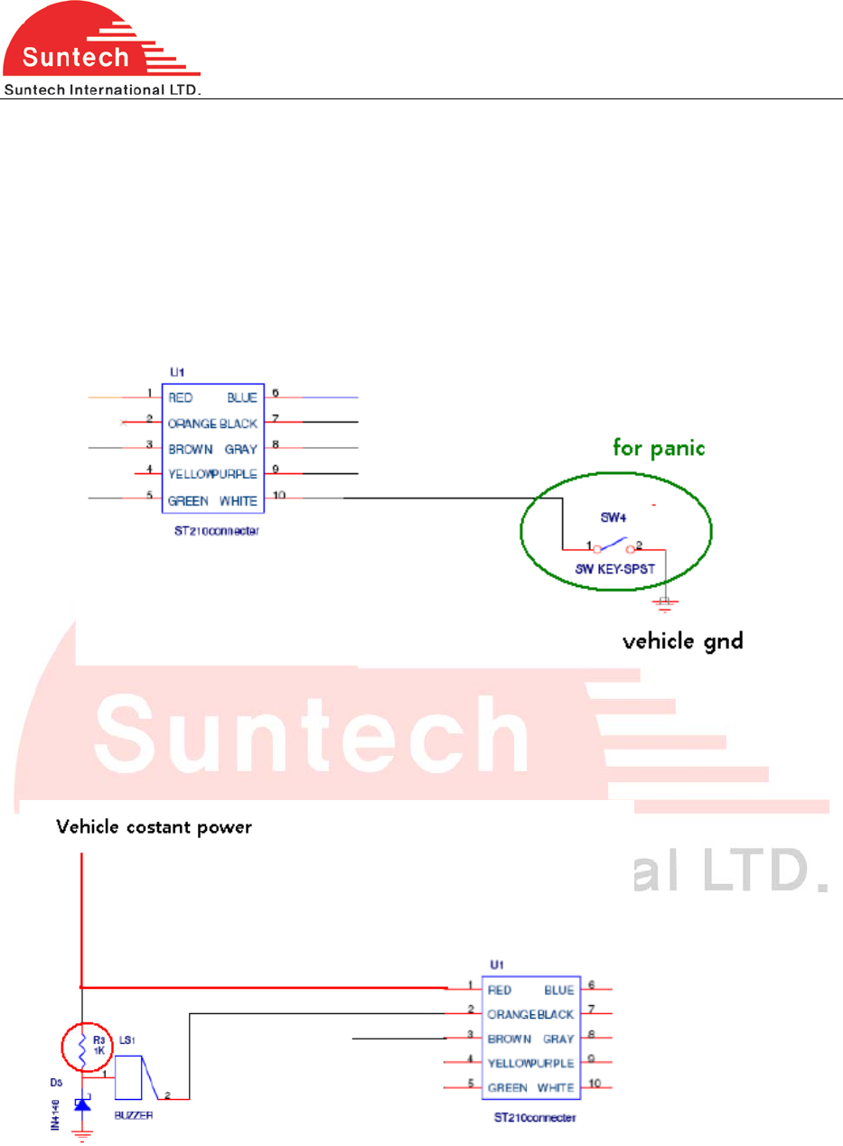
“Orange , brown ” lines of Event cable
- Output line For siren or buzzer
* Set the value of R3(0 ohm or any value) in accordance with the specification of Buzzer or Siren
4
ST215 User Manual
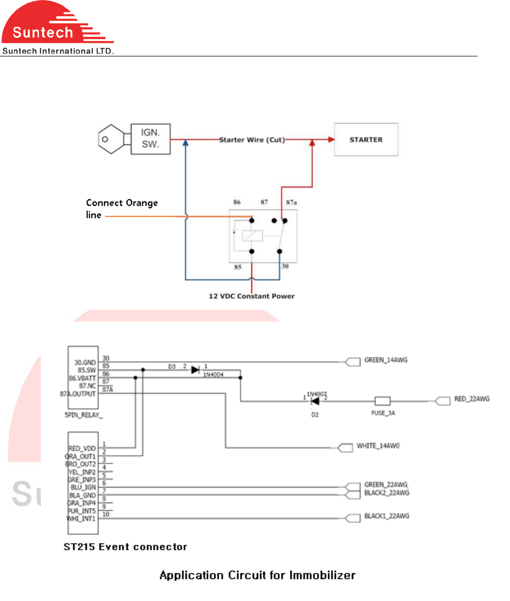
- Output line For immobilizer
Block Diagram for Immobilizer
“Gray , purple ” lines of Event cable
- These two lines are for optional function which is one of RS232, CAN, Input or Output as below
5
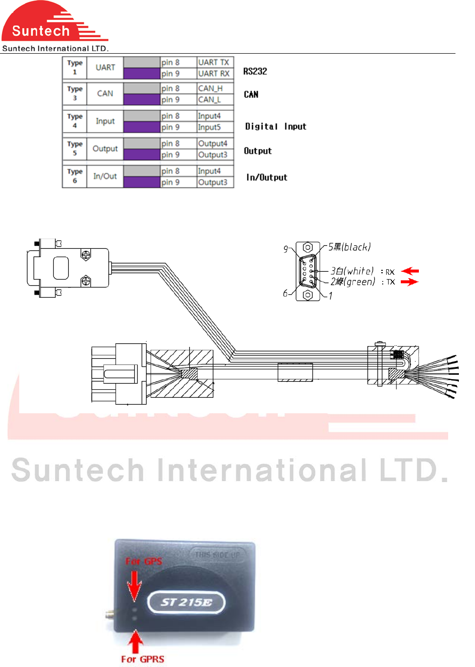
ST215 User Manual
*Check if which function is selected.
For RS232 Interface, Refer to the below
6. Check operation
This device has 2 LEDs on the front that indicates proper operation
LED blinking
For ST210,
Green LED- indicates GPS status
RED LED- indicates GPRS status
*Caution: ST215 device has different LED color
For ST215 ,
RED LED- indicates GPS status
6

ST215 User Manual
BLUE LED- indicates GPRS status
Refer to separate document for detail operation status.
Communicate with control center for checking each Event Lines
7. Confirm start of commercial operation with financial department
The device complies with Part 15 of the FCC Rules. Operation is subject to the following two
conditions:
(1) this device may not cause harmful interference, and (2) this device must accept any
interference received, including interference that may cause undesired operation.
This equipment has been tested and found to comply with the limits for a Class B digital
device, pursuant to part 15 of the FCC Rules. These limits are designed to provide
reasonable protection against harmful interface in a residential installation.
Cautions
Modifications not expressly approved by the party responsible for compliance could void
the user’s authority to operate the equipment.
FCC Radiation Exposure Statement:
This equipment complies with FCC radiation exposure limits set forth for an uncontrolled
environment. This equipment should be installed and operated with minimum distance
20cm between the radiator & your body.
This transmitter must not be co-located or operating in conjunction with any other antenna
or transmitter.
7