Suntech ST240 Quad band GSM GPRS Vehicle Tracker User Manual
Suntech International Ltd. Quad band GSM GPRS Vehicle Tracker
Suntech >
User manual

ST240
User Manual
Suntech International Ltd.
ST240 User Manual
ST240 Installation Guide
1. Decide the location of ST240 and GPS Antenna, and check the cable ways.
- Check whether the location of ST 240 is far away from other electric equipment.
- GPS Antenna must have a sky-view and must be far away from other antenna.
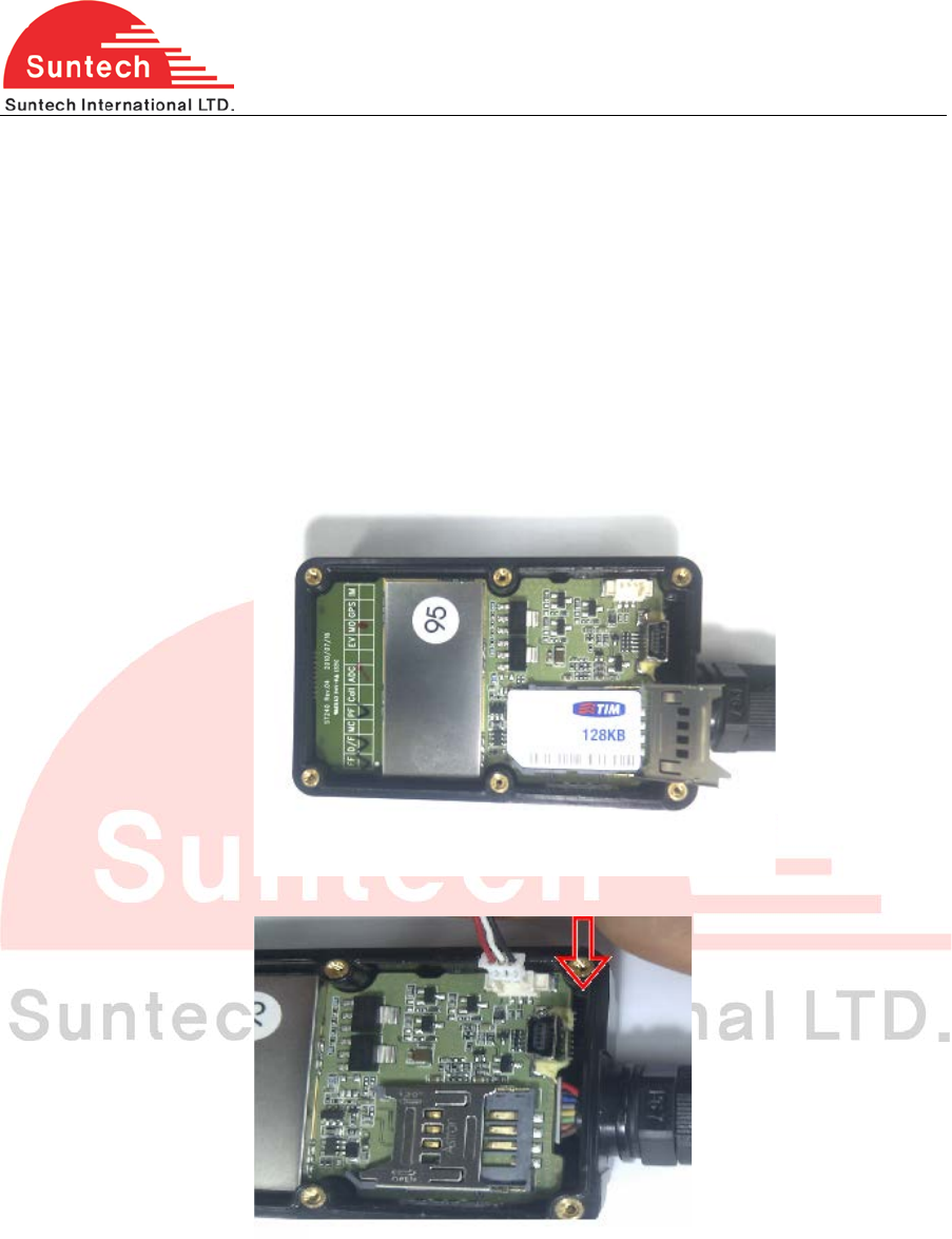
2. Insert SIM card
Steps :
- Open the battery cover, pick out the battery pack.
- Insert SIM into holder and lock it
- Plug the battery connector as shown
2
ST240 User Manual
- Tighten the six screws
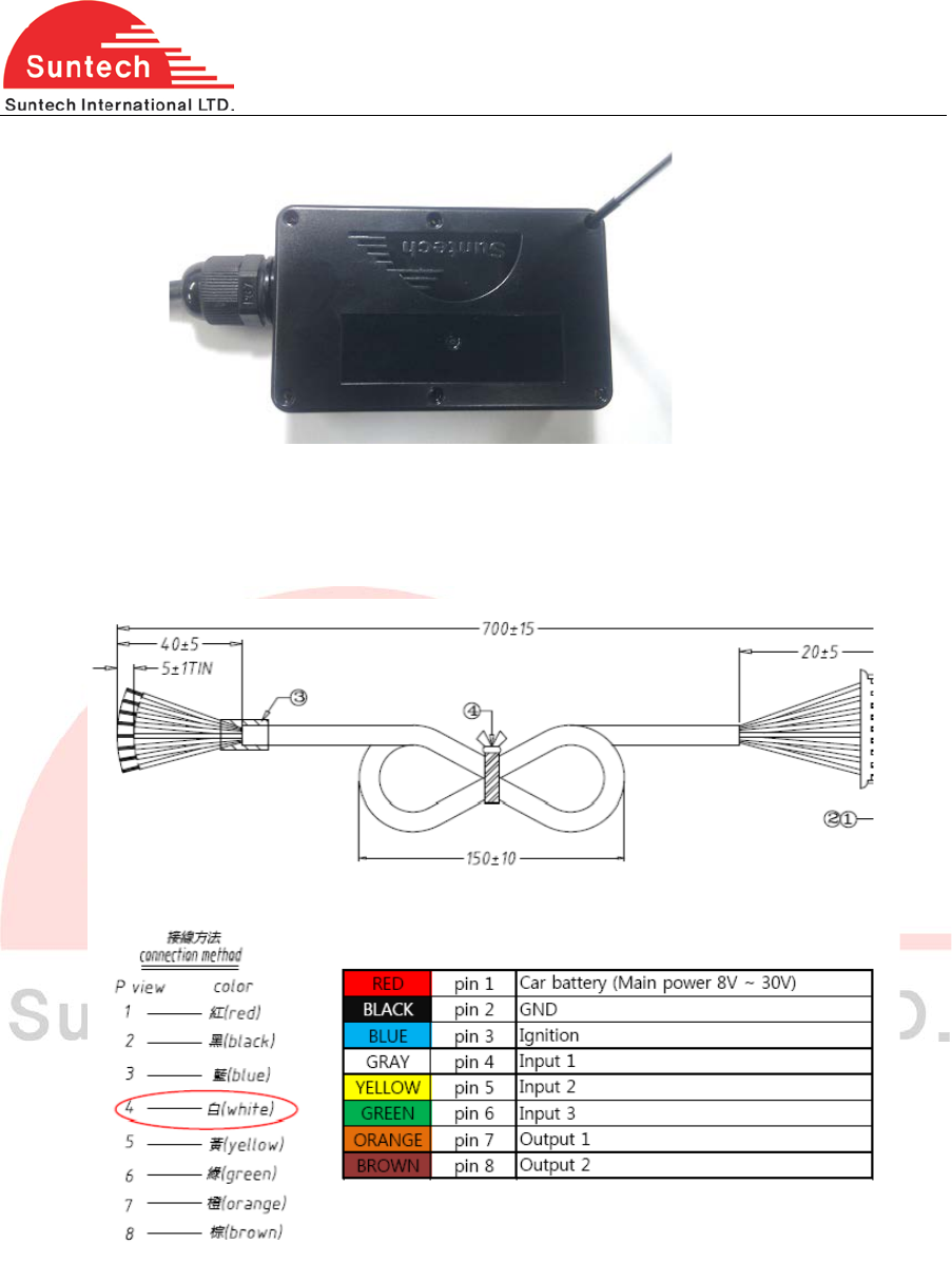
3. Connect Event lines with relevant lines of vehicle.
Event Cable Color pin Description
Red: VCC (8 - 30V)
- Connect the red line to 12 VDC /24 VDC Constant power of vehicle
Black: Ground
- Connect the black line to Ground of vehicle
- Blue: Ignition (8V - 30V) Connect the blue line to an ignition wire of vehicle
Caution : Never connect the red & blue lines together to a constant power source
3
ST240 User Manual
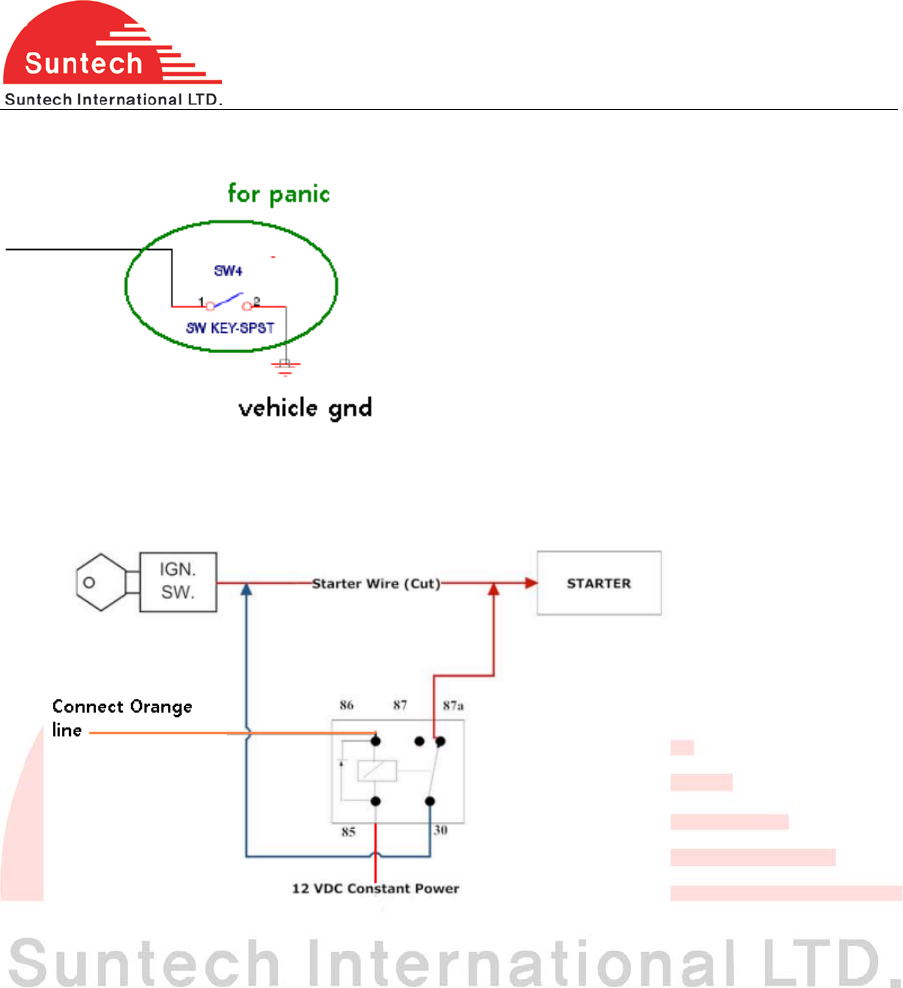
Yellow, Green, White “lines of event cable”
Orange, Brown “lines of event cable”
- Output line For siren or buzzer
- Immobilizer
.
4. Check GPS/GPRS operation and operation with LEDs.
It takes 3~10 minutes for GPS connected.
Green LED- indicates GPS status
RED LED- indicates GPRS status
Caution: Direction of ST240 is very important when installed in the vehicle. Make sure that
top side of ST240
4
ST240 User Manual
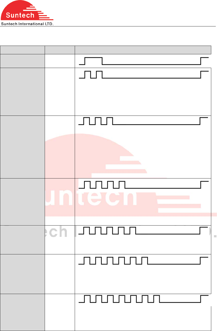
5. Trouble Shooting (LED Indicator)
- Blue LED: Indicates GPRS status.
GPRS Blink Count Remarks
Normal 1
Server Com. Error 2
<Possible Cause>
1. Server or network parameter is wrong.
2. Server is closed.
3. Temporary network barrier
GPRS Com. Error 3
<Possible Cause>
1. Network parameter is wrong.
2. SIM is blocked about GPRS using.
3. Temporary network barrier
4. Weak GPRS signal
5. GPRS antenna connection is not firm.
No Network 4
<Possible Cause>
1. GPRS antenna is disconnected.
2. GPRS antenna or socket of GPRS antenna is broken.
3. Device is broken.
SIM PIN Locked 5
<Possible Cause>
1. SIM PIN is enabled.
Cannot Attach
NW
6
<Possible Cause>
1. Weak GPRS signal.
2. GPRS antenna connection is not firm.
No SIM 7
<Possible Cause>
1. There is no SIM or SIM is not inserted properly.
2. SIM or SIM socket is broken.
5

ST240 User Manual
- RED LED: Indicates GPS status.
GPS Blink Count Remarks
Normal 1
No Fix 2
<Possible Cause>
1. If power on, GPS chipset is trying to find position during
some minutes.
2. GPS antenna lays on weak or no GPS signal position
3. GPS antenna connection is not firm.
GPS Chipset Error
GPS Antenna Error
4
<Possible Cause>
1. GPS antenna is disconnected.
2. GPS antenna or socket of GPS antenna is broken.
3. Unit is broken.
The device complies with Part 15 of the FCC Rules. Operation is subject to the following
two conditions:
(1) this device may not cause harmful interference, and (2) this device must accept any
interference received, including interference that may cause undesired operation.
This equipment has been tested and found to comply with the limits for a Class B digital
device, pursuant to part 15 of the FCC Rules. These limits are designed to provide
reasonable protection against harmful interface in a residential installation.
Cautions
Modifications not expressly approved by the party responsible for compliance could void
the user’s authority to operate the equipment.
FCC Radiation Exposure Statement:
This equipment complies with FCC radiation exposure limits set forth for an uncontrolled
environment. This equipment should be installed and operated with minimum distance
20cm between the radiator & your body.
This transmitter must not be co-located or operating in conjunction with any other
antenna or transmitter.
NOTE : This equipment has been tested and found to comply with the limits for a Class B digital
6

ST240 User Manual
device, pursuant to Part 15 of the FCC Rules. These limits are frequency energy and, if not
installed and used in accordance with the instructions, may cause harmful interference to radio
communications. However, there is no guarantee that interference will not occur in a particular
installation.
If this equipment does cause harmful interference to radio or television reception, which can be
determined by turning the equipment off and on, the user is encouraged to try to correct the
interference by one or more of the following measures:
-- Reorient or relocate the receiving antenna.
-- Increase the separation between the equipment and receiver.
-- Connect the equipment into an outlet on a circuit different from that to which the receiver is
connected.
-- Consult the dealer or an experienced radio/TV technician for help.
7