Suntech ST600 Dual band WCDMA Vehicle Tracker User Manual 600
Suntech International Ltd. Dual band WCDMA Vehicle Tracker 600
UserManual.wiki
>
Suntech
>
ST600 User Manual
User Manual
Navigation menu
Upload a User Manual
Namespaces
Wiki Guide
HTML
PDF
Info
Views
User Manual
Discussion / Help
Navigation


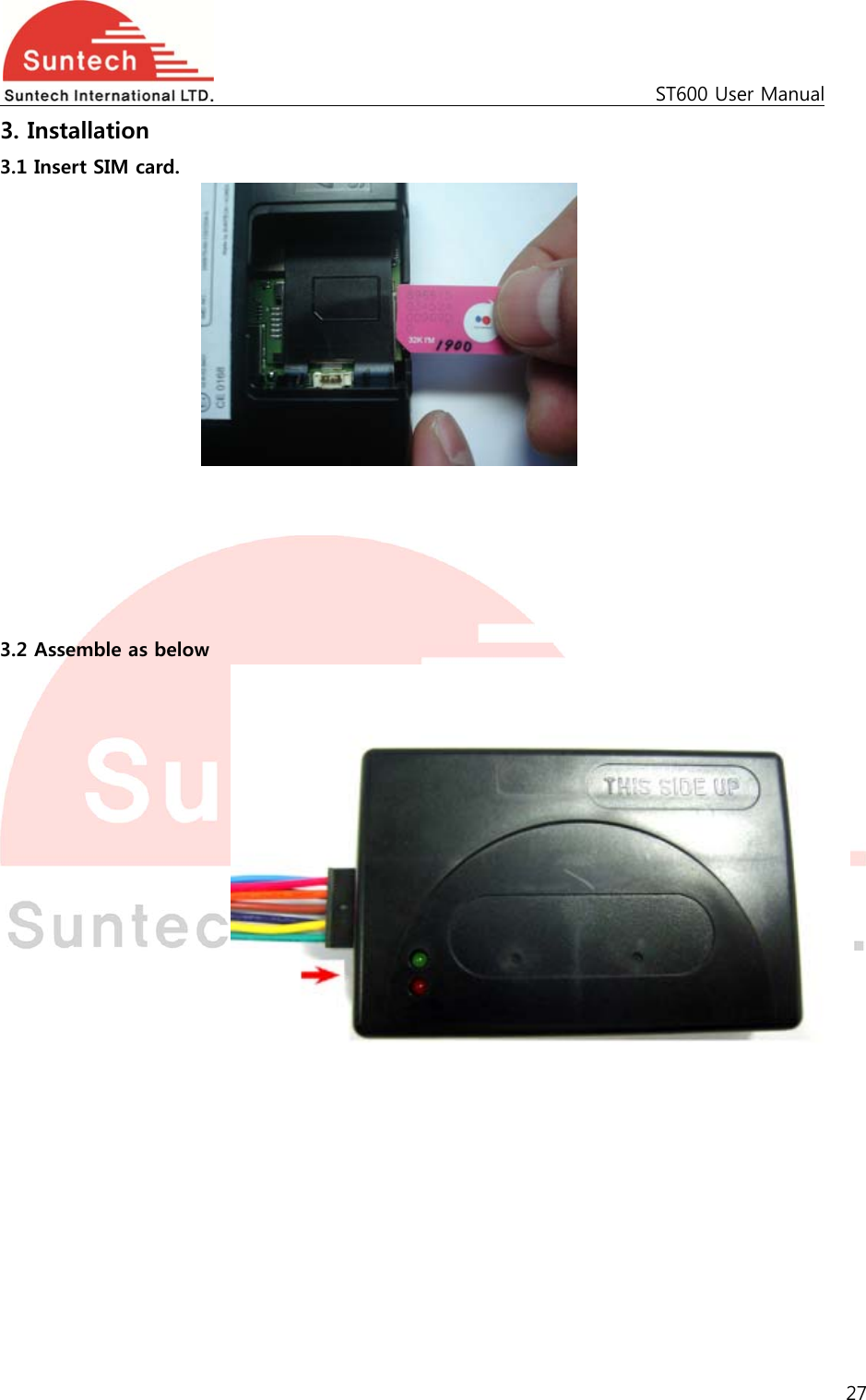
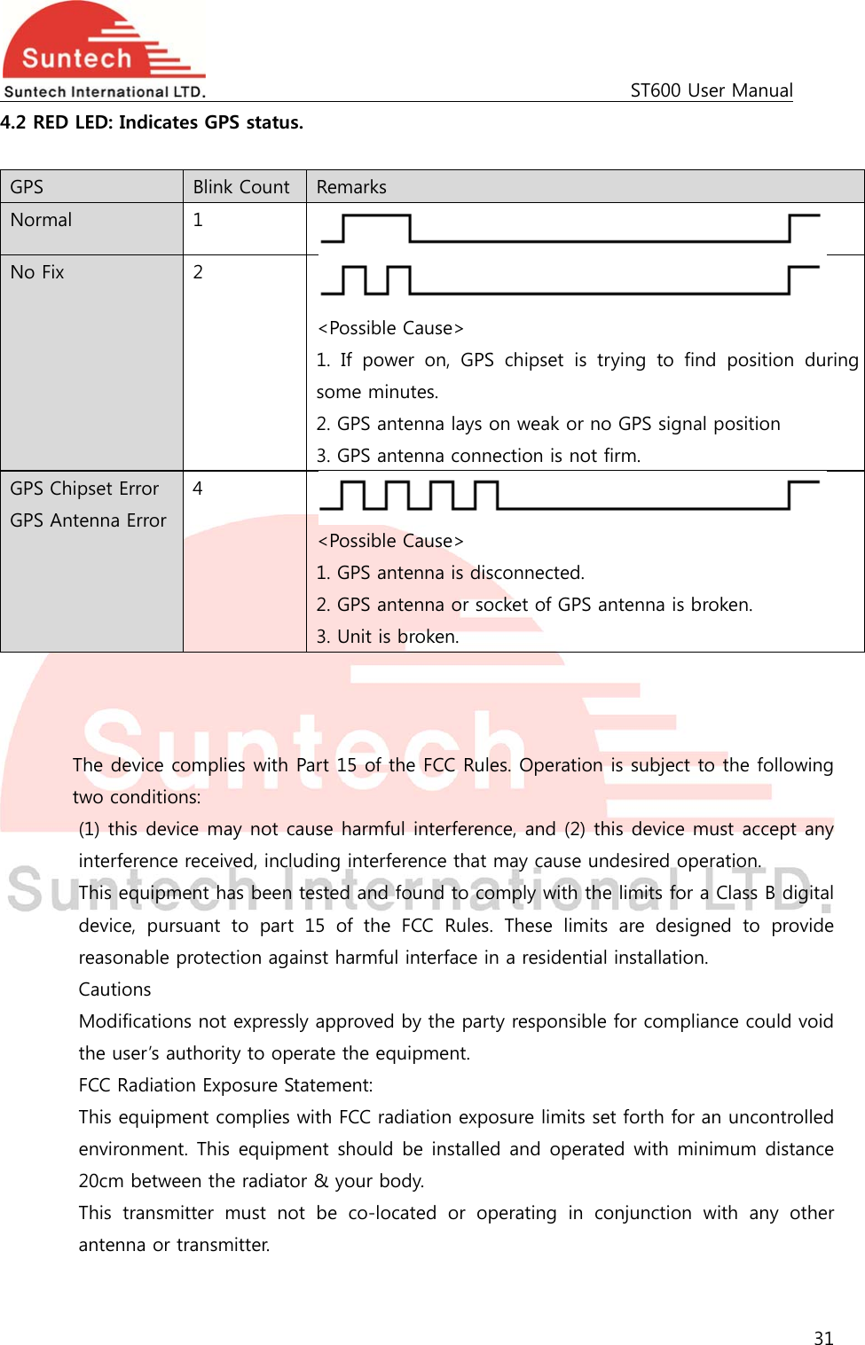
![ST600 User Manual 6 For no use, it should be empty. PIN_NO String PIN Number to release PIN lock if it is enabled <example> [command] ST600NTW;850000;02;0;internet;;;111.111.111.111;8600;;;; [response] ST600NTW;Res;850000;010;0;internet;;; 111.111.111.111;8600;;;; ST600NTW;Res;850000;010;A1;tim.br;tim;tim; 111.111.111.111;8600;;;; <notes> ** If network does not require User ID and Password, these fields should be empty. Automatic WCDMA Set It the device is set to ‘Automatic WCDMA Set’, the device set WCDMA parameters automatically depending on inserted SIM. For example, if Airtel SIM is inserted, the device set AUTH to 0, APN to “aitelWCDMA.com”, USER_ID and USER_PASS to empty. And the device reports response string after adding real WCDMA parameters when automatic WCDMA set is selected. 4-2. Report Parameter Setting HDR DEV_ID VER T1 T2 T3 A1 SND_DIST T4 SMS_T1 SMS_T2 SMS_PACK_NO ANGLE_RPT RPT_TYPE ● Definition : Set parameters related on report interval. Field Definitions Unit Remark HDR “ST600RPT” Command type DEV_ID 6 char. Device ID VER “02” Protocol Version T1 String Sec Interval for sending status report in parking mode Range : 0 ~ 86400 If 0, report in parking will be sent only one time when vehicle starts parking. T2 String Sec Interval for sending status report in driving mode Range : 0 ~ 60000](https://usermanual.wiki/Suntech/ST600/User-Guide-2549044-Page-6.png)
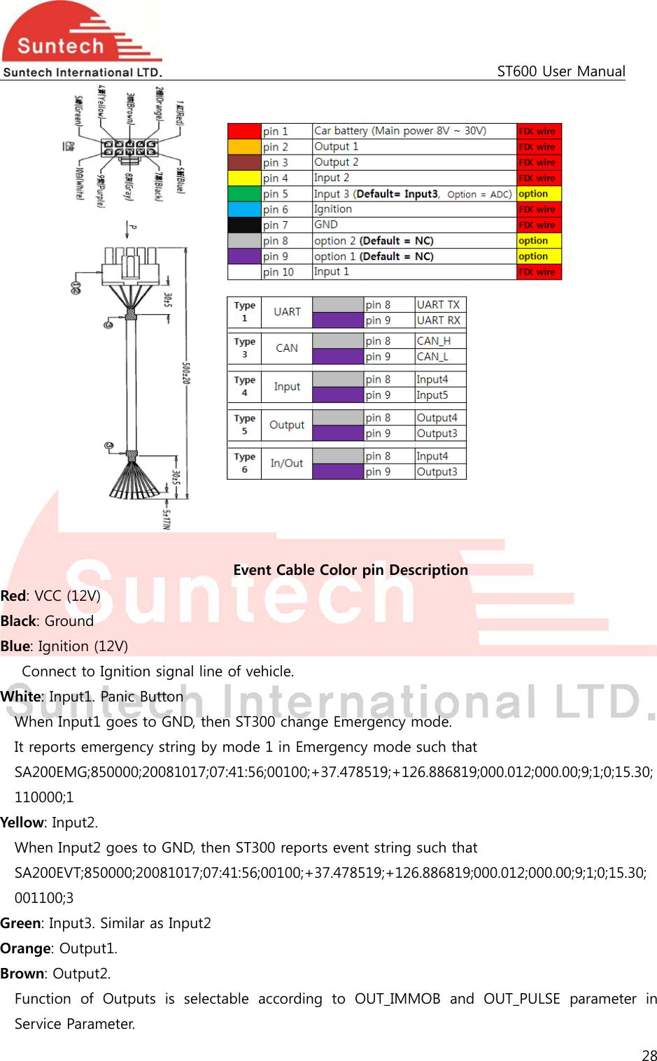
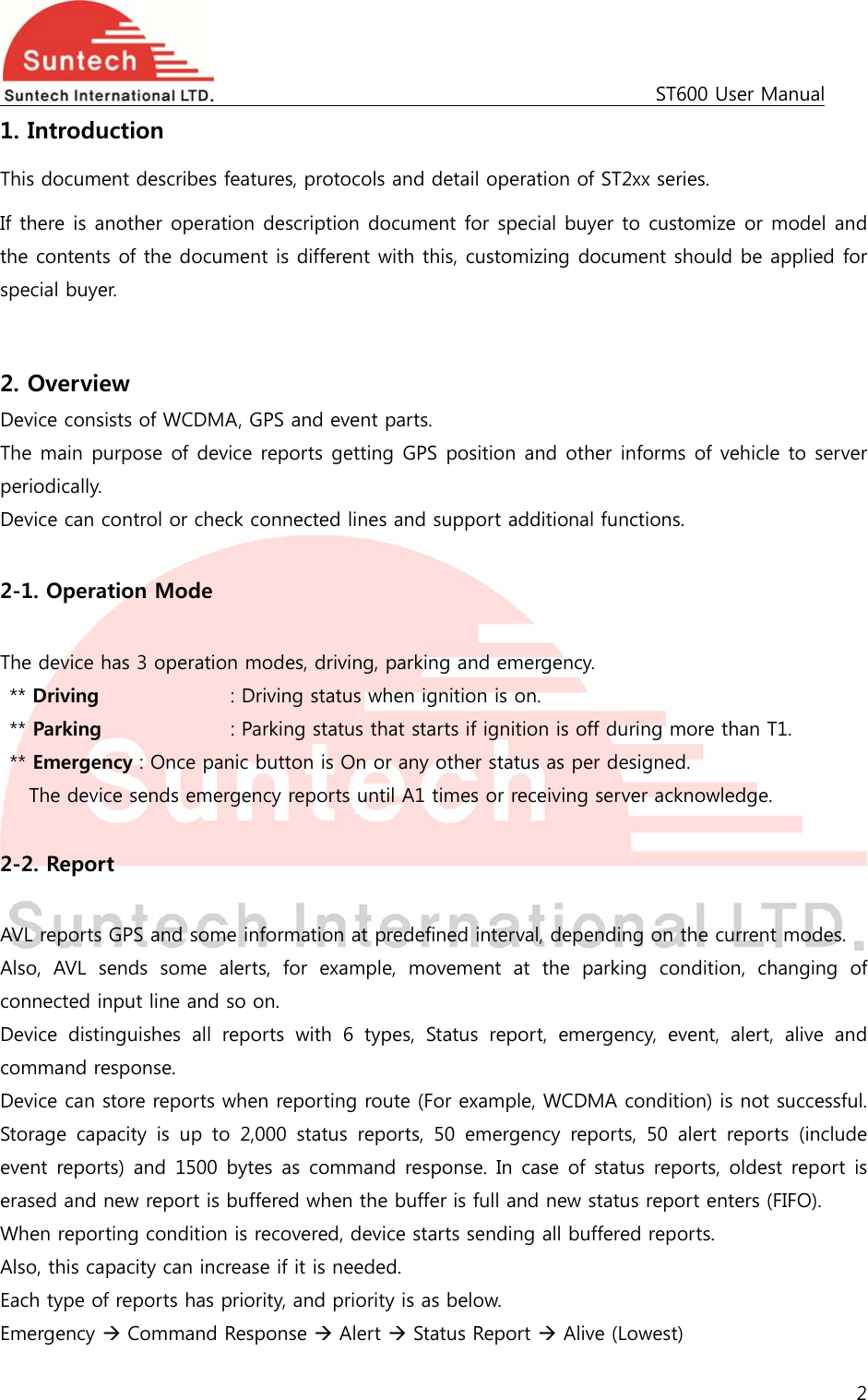
![ST600 User Manual 7 If 0, report in driving will be sent only one time when vehicle starts driving. T3 String Sec Interval for sending status report in emergency mode Range : 0 ~ 9999 If 0, emergency report will be sent only one time when emergency state occurs. A1 String Number of attempts for emergency report until the device gets acknowledge from server If 0, no emergency report will be sent. SND_DIST String Meter Distance interval for sending status report. Range : 0 ~ 60000 (60km) If 0, status report related on moving distance is disabled. If not 0, stats report is send when traveled distance reaches predefined SND_DIST. T4 String Sec Interval for sending keep alive string SMS_T1 String Min Interval for sending status report in parking mode SMS_T2 String Min Interval for sending status report in driving mode SMS_PACK_NO String Report No in one SMS message ANGLE_RPT String Degree Report STT message if it’s greater than ANGLE_RPT. 0 : Disable Range : 1 ~ 179 RPT_TYPE String Set the type of reporting. 0: FIFO : First in First Out. 1: LIFO : Last In First Out. <example> [command] ST600RPT;850000;02;180;120;60;3;0;0;0;0;0;0;0 [response] ST600RPT;Res;850000;010;180;120;60;3;0;0;0;0;0;0;0 <notes> ** If report interval is set big number, network may disconnect WCDMA connection because WCDMAcommunication is not progressed for a long time. So, unit may not receive command by WCDMA. T4 is for protecting against this disconnection by sending short data with short term. ** Alive report can be sent only when the device has no data to send during T4 interval. 4-3. Event Parameter Setting](https://usermanual.wiki/Suntech/ST600/User-Guide-2549044-Page-7.png)
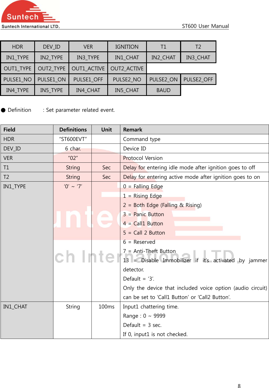
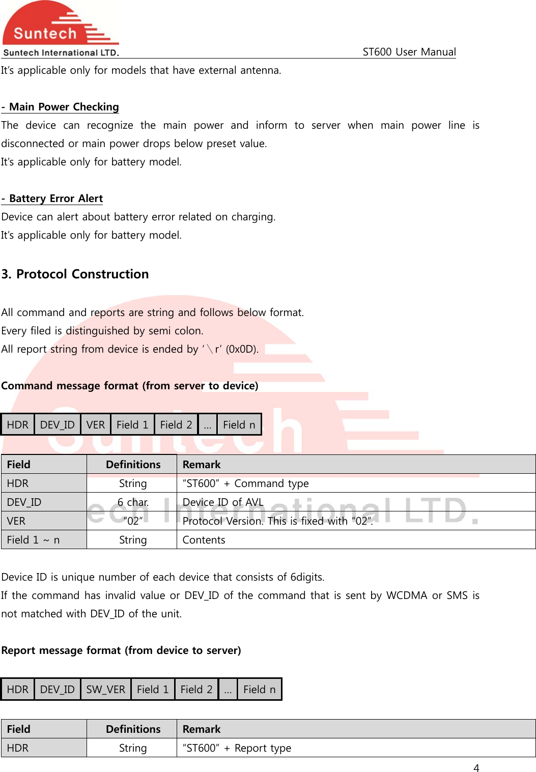
![ST600 User Manual 10 <example> [command] ST600EVT;850000;02;1;60;0;3;2;2;30;20;20;1;0;1;0;0;0;0;0;0;0;0;0;0;0;0 [response] ST600EVT;Res;850000;010;1;60;0;3;2;2;30;20;20;1;0;1;0;0;0;0;0;0;0;0;0;0;0;0 <notes> ** If IGNITION is set to ‘0’, device doesn’t check driving or parking state of the vehicle. It reports status string with idle mode always, and cannot support parking lock and the service that enters sleep or deep sleep automatically when the vehicle is parked. ** If IGNITION is set to ‘2’, the device checks driving or parking state of the vehicle with voltage range of vehicle’s battery. We named it as ‘Virtual Ignition’. Virtual ignition can operate when the device installed into real vehicle and it may be need adjustment of voltage range for special vehicle. For setting method, please refer 6.3. ** In case of pulse, pulse time may have tolerance about dozens of ms. ** Immobilizer, LED Blink line and Buzzer type cannot set both OUT1 and OUT2 simultaneously. ** In case that a event is set to “door sensor”, active state means door is opened. ** If device has the Handsfree kit, each time the volume up button is pressed once, the speaker volume is turned up as below. 0 -> 1 -> 2 -> 3 -> 4 ->5 ->0 -> 1 -> 2 ->3 -> 4 -> 5 - > 0 -> 1 -> …. (0 : Volume mute, 5 :Max Volume) Type of no supported event line is fixed to “No Use”. Below table is for example of 4 line event model. Field Definitions Unit Remark HDR “ST600EVT” Command type DEV_ID 6 char. Device ID VER “02” Protocol Version IGNITION ‘0’ ~ ‘2’ Ignition using state 0 : Not use ignition 1 : Use ignition Line 2 : Virtual ignition(power) 3 : Virtual ignition (motion) T1 String Sec Delay for entering idle mode after ignition goes to off T2 String Sec Delay for entering active mode after ignition goes to on](https://usermanual.wiki/Suntech/ST600/User-Guide-2549044-Page-10.png)
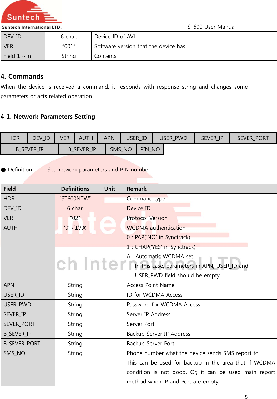
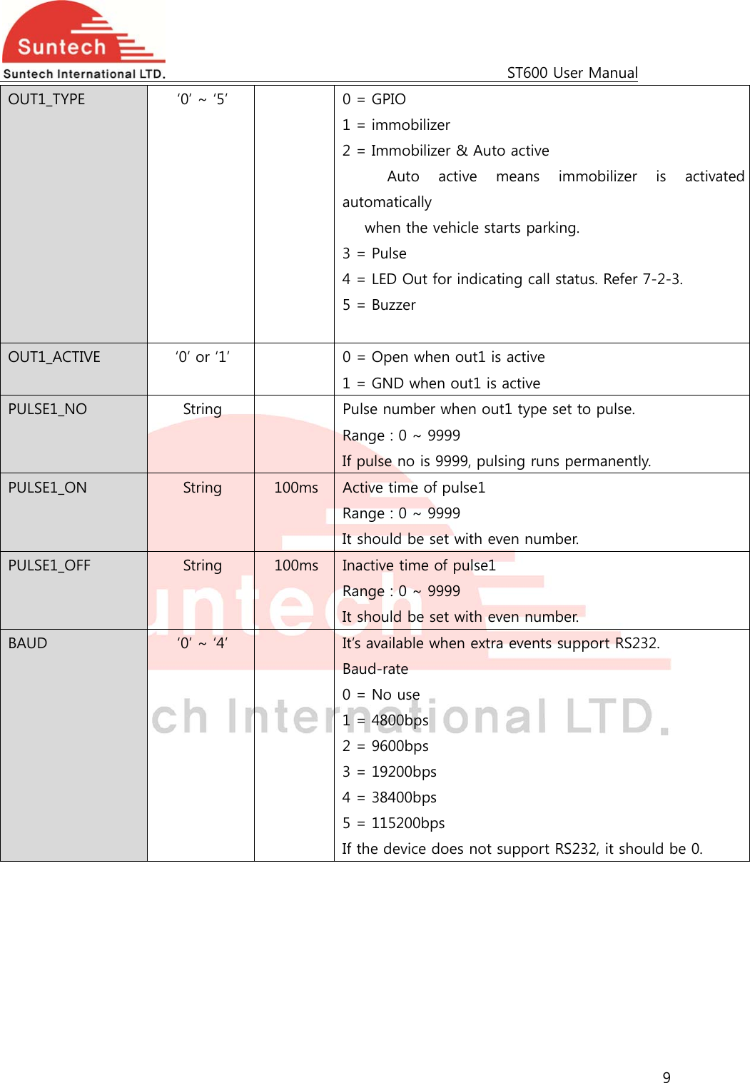
![ST600 User Manual 11 IN1_TYPE ‘0’ ~ ‘5’ 0 = Falling Edge 1 = Rising Edge 2 = Both Edge (Falling & Rising) 3 = Panic Button 4 = Call1 Button 5 = Call 2 Button 6 = Reserved 7 = Anti-Theft Button 13 = Disable Immobilizer if it’s activated by jammer detector. Default = ‘3’. Only the device that included voice option (audio circuit) can be set to ‘Call1 Button’ or ‘Call2 Button’. IN1_CHAT String 100ms Input1 chattering time. Range : 0 ~ 9999 Default = 3 sec. If 0, input1 is not checked. OUT1_TYPE ‘7’ 7 = No Use OUT1_ACTIVE ‘0’ or ‘1’ PULSE1_NO ‘0’ PULSE1_ON ‘0’ PULSE1_OFF ‘0’ BAUD ‘0’ 0 = No use <example> [command] ST600EVT;850000;02;1;60;0;3;2;2;30;20;20;1;0;1;0;0;0;0;0;0;0;0;0;0;0;0 [response] ST600EVT;Res;850000;010;1;60;0;3;8;8;30;0;0;6;6;1;0;0;0;0;0;0;0;8;8;0;0;0 <notes> ** In case of event 4 line model, IN2_TYPE, IN3_TYPE, IN4_TYPE, IN5_TYPE, OUT1_TYPE and OUT2_TYPE should be ‘No Use’. Type and chat time of non used event lines are set to ‘No Use’ and ‘0’ automatically although these filed of command is set to other value. 4-4. WCDMA Parameter Setting HDR DEV_ID VER SMS_LOCK SMS_MT1 SMS_MT2 SMS_MT3](https://usermanual.wiki/Suntech/ST600/User-Guide-2549044-Page-11.png)
![ST600 User Manual 12 SMS_MT4 IN_CALL_LOCK CALL_MT1 CALL_MT2 CALL_MT3 CALL_MT4 CALL_MT5 CALL_MO1 CALL_MO2 ● Definition : Set parameters related SMS or Call. Field Definitions Unit Remark HDR “ST600WCDMA” Command type DEV_ID 6 char. Device ID VER “02” Protocol Version SMS_LOCK ‘0’ or ‘1’ Lock of Receiving Commands by SMS Disable (0) / Enable (1) If enabled, only commands that receives from SMS_MT1 ~ MT3 number can be accepted. SMS_MT1 String Up to 20 char. Phone number for SMS commands SMS_MT2 String Up to 20 char. Phone number for SMS commands SMS_MT3 String Up to 20 char. Phone number for SMS commands SMS_MT4 String Up to 20 char. Phone number for SMS commands IN_CALL_LOCK ‘0’ or ‘1’ Lock of Incoming Call Disable (0) / Enable (1) If enabled, only call from CALL_MT1 ~ MT5 number can be accepted. CALL_MT1 String Up to 20 char. Phone number for call CALL_MT2 String Up to 20 char. Phone number for call CALL_MT3 String Up to 20 char. Phone number for call CALL_MT4 String Up to 20 char. Phone number for call CALL_MT5 String Up to 20 char. Phone number for call CALL_MO1 String Up to 20 char. Phone number for outgoing call from device CALL_MO2 String Up to 20 char. Phone number for outgoing call from device <example> [command] ST600WCDMA;850000;02;0;;;;;0;;;;;;; [response] ST600WCDMA;Res;850000;010;0;;;;;0;;;;;;; <notes> ** When SMS or Call numbers are not set, that field should be empty.](https://usermanual.wiki/Suntech/ST600/User-Guide-2549044-Page-12.png)
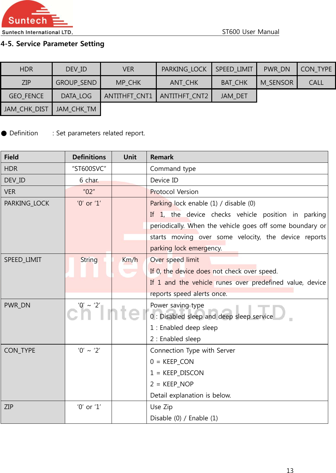
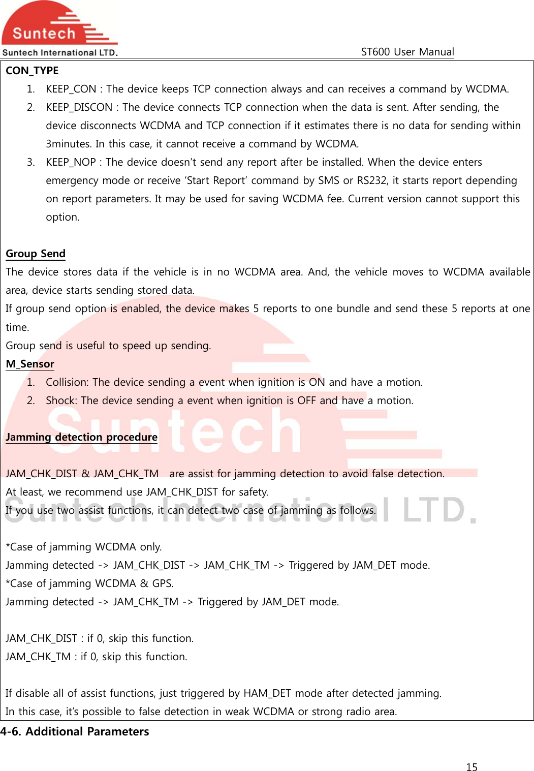
![ST600 User Manual 14 GROUP_SEND ‘0’ or ‘1’ Group Send for stored data 0 : Disable 1 : Enable. One packet can include up to 5 reports. Group send is explained below. MP_CHK ‘0’ or ‘1’ Main Power Disconnection Check Disable (0) / Enable (1) ANT_CHK ‘0’ or ‘1’ GPS Antenna Connection Error Check Disable (0) / Enable (1) BAT_CHK ‘0’ or ‘1’ Backup Battery Error Check Disable (0) / Enable (1) M_SENSOR ‘0’ ~’4’ Motion Sensor Motion Collision Shock 0 Disable Disable Disable 1 Enable Disable Disable 2 Disable Disable Enable 3 Enable Disable Enable 4 Disable Enable Disable 5 Enable Enable Disable 6 Disable Enable Enable 7 Enable Enable Enable CALL ‘0’ or ‘1’ Support Call with headset Disable (0) / Enable (1) GEO_FENCE ‘0’ or ‘1’ Support Geo-fence Disable (0) / Enable (1) DAT_LOG ‘0’ or ‘1’ Log out with RS232 0 = No Use 1 = Enable getting saved log data by RS232 <example> [command] ST600SVC;850000;02;1;120;0;0;0;0;1;1;1;0;0;0;0;0;0;0;0;0 [response] ST600SVC;Res;850000;010;1;120;0;0;0;0;1;1;1;0;0;0;0;0;0;0;0;0 <notes> ** Function of M_SEMSOR can be used with the model that has motion sensor. If shock or collision detection is enabled, device will report to server when gets any shock or collision. ** If this parameter has been customized, This table should be disregarded and you should follow customized operation document.](https://usermanual.wiki/Suntech/ST600/User-Guide-2549044-Page-14.png)
![ST600 User Manual 16 HDR DEV_ID VER SVR_TYPE B_SVR_TYPE UDP_ACK DEV_PORT ● Definition : Setting additional parameter requested. Field Definitions Unit Remark HDR “ST600ADP” Command type DEV_ID 6 char. Device ID VER “02” Protocol Version SVR_TYPE ‘T’ / ‘U’ Server Protocol Type T : TCP U : UDP B_SVR_TYPE ‘T’ / ‘U’ Backup Server Protocol Type T : TCP U : UDP UDP_ACK ‘0’ ~ ‘3’ ACK from Server when UPD is used. 0 : No use 1 : ACK when the server receives reports except alive. 2 : ACK when the server receives reports except STT and alive report. 3 : ACK when the server receives emergency report. Command response doesn’t need ACK. DEV_PORT String Device’s port for receiving command from UDP server. It can be used only when UDP server is used. If ‘0’ or empty, the device would use port 9000. If not zero, the device can receive commands with port DEV_PORT. Reserved ‘0’ Reserved ‘0’ Reserved ‘0’ Reserved ‘0’ Reserved ‘0’ Reserved ‘0’ <example> [command] ST600ADP;850000;02;U;T;2;9000;0;0;0;0;0;0 [response] ST600ADP;Res;850000;022;U;T;2;9000;0;0;0;0;0;0 <notes>](https://usermanual.wiki/Suntech/ST600/User-Guide-2549044-Page-16.png)
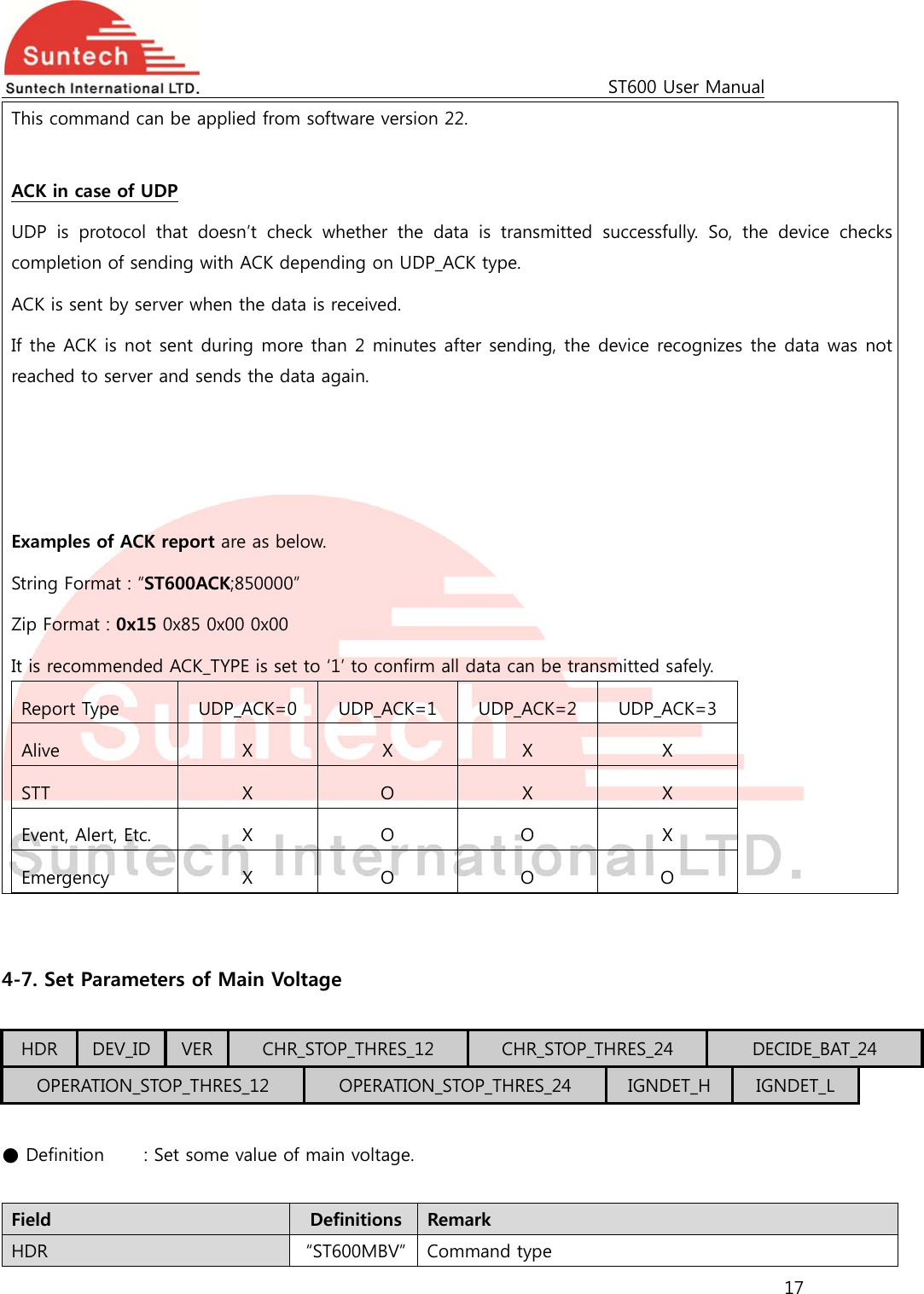
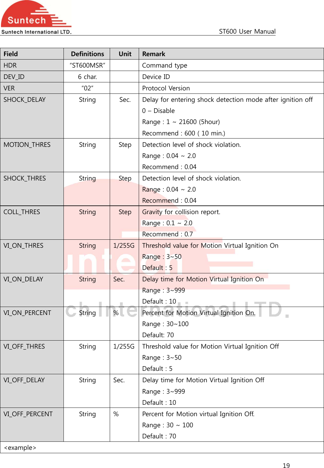
![ST600 User Manual 18 DEV_ID 6 char. Device ID VER “02” Protocol Version CHR_STOP_THRES_12 String Voltage value to stop backup battery charging in 12V vehicle. CHR_STOP_THRES_24 String Voltage value to stop backup battery charging in 24V vehicle. DECIDE_BAT_24 String Voltage value to check whether the vehicle’s battery is 12V or 24V. OPERATION_STOP_THRES_12 String Voltage value to protect vehicle battery. The device operation stops if car battery voltage is lower than this value in vehicle that has 12V power. OPERATION_STOP_THRES_24 String Voltage value to protect vehicle. The device operation stops if car battery voltage is lower than this value in vehicle that has 24V power. IGNDET_H String In case of virtual ignition, the vehicle can recognize driving state when vehicle power is more than IGNDET_H. Default = ‘0’ IGNDET_L String In case of virtual ignition, the vehicle can recognize parking state when vehicle power is less than IGNDET_L.Default = ‘0’ <example> [command] ST600MBV;850000;02;10.5;22;19;8.00;18.00;0;0 [response] ST600MBV;Res;850000;122;10.5;22;19;8.00;18.00;0;0 <note> IGNDET_H and IGNDET_L are ‘0’, device check parking and driving automatically. 4-8. Set Parameters of Motion Sensor HDR DEV_ID VER CHR_STOP_THRES_12 CHR_STOP_THRES_24 DECIDE_BAT_24 OPERATION_STOP_THRES_12 OPERATION_STOP_THRES_24 IGNDET_H IGNDET_L VI_ON_THRES VI_ON_DELAY VI_ON_PERCENT VI_OFF_THRES VI_OFF_DELAY VI_OFF_PERCENT ● Definition : Set motion sensor parameters](https://usermanual.wiki/Suntech/ST600/User-Guide-2549044-Page-18.png)
![ST600 User Manual 20 [command] ST600MSR;;02;600;0.04;0.04;0.7;5;10;70;5;10;70 [response] ST600MSR;Res;852588;128;600;0.04;0.04;0.70;5;10;70;5;10;70 <notes> * For the shock level, we recommend it to set to 0.04. if it's over than 0.04, the sensor will be more insensitive as it for shock detection. 4-11. Control Command HDR DEV_ID VER CMD_ID ● Definition : Controls some functions. Field Definitions Unit Remark HDR “ST600CMD” Command type DEV_ID 6 char. Device ID VER ‘01’ Protocol Version CMD_ID String Control command content Caution : If it’s not correct the Unit ID, ignored. 4-11-1. Status Request ● Definition : Location poll, request of the status report. Field Definitions Unit Remark CMD_ID “StatusReq” Status request If received, the device sends status string instantly. <example> <example> [command] ST600CMD;850000;02;StatusReq [response] ST600STT;850000;010;20090724;07:12:16;00129;+37.479995;+126.885815;000.029;000.00; 7;1;0;15.33;100000;2;0002](https://usermanual.wiki/Suntech/ST600/User-Guide-2549044-Page-20.png)
![ST600 User Manual 21 4-11-2. Reset ● Definition : Reset all of parameters. Field Definitions Unit Remark CMD_ID “Reset” Reset Initialize all parameters with factory value and reboot the device. <example> [command] ST600CMD;850000;02;Reset [response] ST600CMD;Res;850000;010;Reset 4-11-3. Preset ● Definition : Reset all of parameters. Field Definitions Unit Remark CMD_ID “Preset” Report parameter setting values and current device status. Response includes network, report, event, WCDMA and service parameters. It includes status of device, also. <example> [command] ST600CMD;850000;02;Preset [response] ST600CMD;Res;850000;010;Preset; NTW;0;internet;;;111.111.111.111;8600;;;;1234; RPT;60;180;120;60;3;0;0;;;; EVT;1;60;0;3;2;2;30;20;20;1;1;1;0;0;0;0;0;0;0;0;0;0;0;0; WCDMA;0;;;;;0;;;;;;;; SVC;1;120;0;0;0;0;1;1;1;0;0;0;0 DEV;0;0;0;0 [response] event 4 line model NTW;0;internet;;;111.111.111.111;8600;;;;1234; RPT;60;180;120;60;3;0;0;;;; EVT;1;60;0;3;8;8;30;0;0;6;6;1;0;0;0;0;0;0;0;0;0;0;0;0; WCDMA;0;;;;;0;;;;;;;; SVC;1;120;0;0;0;0;1;1;1;0;0;0;0](https://usermanual.wiki/Suntech/ST600/User-Guide-2549044-Page-21.png)
![ST600 User Manual 22 DEV;0;0;0;0 <notes> ** After power on, device sends response string of preset once. ** DEV filed informs current status of device as below. OUT1 0 = Disable 1 = Enable OUT2 0 = Disable 1 = Enable PWR_DN 0 = Normal 1 = Sleep 2 = Deep sleep BAT_CON 0 = Backup battery is disconnected. 1 = Backup battery is connected. Field Definitions Unit Remark CMD_ID “PresetA” Report all parameters including additional parameter. <example> [command] ST600CMD;850000;02;PresetA [response] ST600CMD;Res;850000;010;PresetA; NTW;0;internet;;;111.111.111.111;8600;;;;1234; RPT;60;180;120;60;3;0;0;;;; EVT;1;60;0;3;2;2;30;20;20;1;1;1;0;0;0;0;0;0;0;0;0;0;0;0; WCDMA;0;;;;;0;;;;;;;; SVC;1;120;0;0;0;0;1;1;1;0;0;0;0; ADP;U;T;2;9000;0;0;0;0;0;0; DEV;0;0;0;0;0;0;0;0 <notes> ** This command can be applied from software version 22. ** DEV filed informs current status of device as below. OUT1 0 = Disable 1 = Enable OUT2 0 = Disable 1 = Enable PWR_DN 0 = Normal 1 = Sleep 2 = Deep sleep BAT_CON 0 = Backup battery is disconnected. 1 = Backup battery is connected. TRACKING 0 = Stop Tracking Anti-Theft 0 = Disable Reserved Reserved](https://usermanual.wiki/Suntech/ST600/User-Guide-2549044-Page-22.png)
![ST600 User Manual 23 1 = Start Tracking 1 = Enable 4-11-4. ACK of Emergency ● Definition : Stop emergency report. Field Definitions Unit Remark CMD_ID “AckEmerg” Acknowledgement of emergency report. The device will stop emergency reports if it is in emergency state. <example> [command] ST600CMD;850000;02;AckEmerg [response] ST600CMD;Res;850000;010;AckEmerg 4-11-5. Enable1 ● Definition : Active Output1. Field Definitions Unit Remark CMD_ID “Enable1” Enable Output1 <example> [command] ST600CMD;850000;02;Enable1 [response] ST600CMD;Res;850000;010;Enable1 [response] ST600CMD;Res;850000;010;Enable1NoUse (in case that IN type is set to ‘No Use’). <notes> ** Output1 line goes to active status. ** If OUT1 set with immobilizer, output1 line goes to active status gradually with pulse in driving mode. ** If OUT1 set with pulse type, output1 line generates pulse and returns inactive state after pulsing out automatically. 4-11-6. Disable1](https://usermanual.wiki/Suntech/ST600/User-Guide-2549044-Page-23.png)
![ST600 User Manual 24 ● Definition : Inactive Output1. Field Definitions Unit Remark CMD_ID “Disable1” Disable Output1 <example> [command] ST600CMD;850000;02;Disable1 [response] ST600CMD;Res;850000;010;Disable1 [response] ST600CMD;Res;850000;010;Disable1NoUse (in case that IN type is set to ‘No Use’). <notes> ** Output1 line goes to inactive status. 4-11-9. Request IMSI ● Definition : Request the unique SIM ID. Field Definitions Unit Remark CMD_ID “ReqIMSI” Request IMSI (unique SIM ID) If received, device sends IMSI of using SIM. <example> [command] ST600CMD;850000;02;ReqIMSI [response] ST600CMD;Res;850000;010;ReqIMSI;724031111553779 4-11-10. Request ICCID ● Definition : Request the ICCID. Field Definitions Unit Remark CMD_ID “ReqICCID” Request ICCID (sequence number that is displayed on SIM) If received, device sends ICCID of using SIM. <example> [command] ST600CMD;850000;02;ReqICCID [response] ST600CMD;Res;850000;010;ReqICCID;89550230000084256668 4-11-11. ReqVer ● Definition : Request software version.](https://usermanual.wiki/Suntech/ST600/User-Guide-2549044-Page-24.png)
![ST600 User Manual 25 Field Definitions Unit Remark CMD_ID “ReqVer” Request device version Device reports Model, Buyer, Protocol and S/W release version. <example> [command] ST600CMD;850000;02;ReqVer [response] ST600CMD;Res;850000;010;ReqVer;ST600E_SAMPLE_STBASE_001 4-11-12. Erase All ● Definition : Erase all of data in buffer. Field Definitions Unit Remark CMD_ID “EraseAll” Erase saved all reports and disable outputs. This is needed to initialize just before device is delivered to a customer. <example> [command] ST600CMD;850000;02;EraseAll [response] ST600CMD;Res;850000;010;EraseAll 4-11-13. Initialize Traveled Distance ● Definition : Initialize the travel distance. Field Definitions Unit Remark CMD_ID “InitDist” Set traveled distance to 0. <example> [command] ST600CMD;850000;02;InitDist [response] ST600CMD;Res;850000;010;InitDist 4-11-14. Initialize Message Number](https://usermanual.wiki/Suntech/ST600/User-Guide-2549044-Page-25.png)
![ST600 User Manual 26 ● Definition : Initialize the message sequence number. Field Definitions Unit Remark CMD_ID “InitMsgNo” Set message number to 0. <example> [command] ST600CMD;850000;02;InitMsgNo [response] ST600CMD;Res;850000;010;InitMsgNo 4-11-23. Reboot ● Definition : reboot unit. Field Definitions Unit Remark CMD_ID “Reboot” Reboot device. <example> [command] ST600CMD;850000;02;Reboot [response] ST600CMD;Res;850000;010;Reboot 4-11-24. Request SIM IP Address ● Definition : Request of the local IP address in SIM card. Field Definitions Unit Remark CMD_ID “ReqSIMIP” SIM card IP request <example> [command] ST600CMD;850000;02;ReqSIMIP [response] ST600CMD;Res;850000;010;ReqSIMIP;172.16.18.6](https://usermanual.wiki/Suntech/ST600/User-Guide-2549044-Page-26.png)