Sunwave Communications R205 Booster User Manual Preface
Sunwave Communications Co., Ltd Booster Preface
UserManual.wiki
>
Sunwave Communications
>
R205 User Manual
>
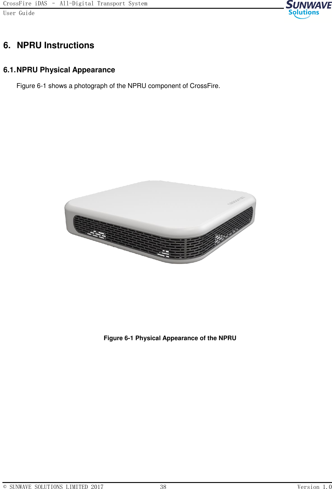
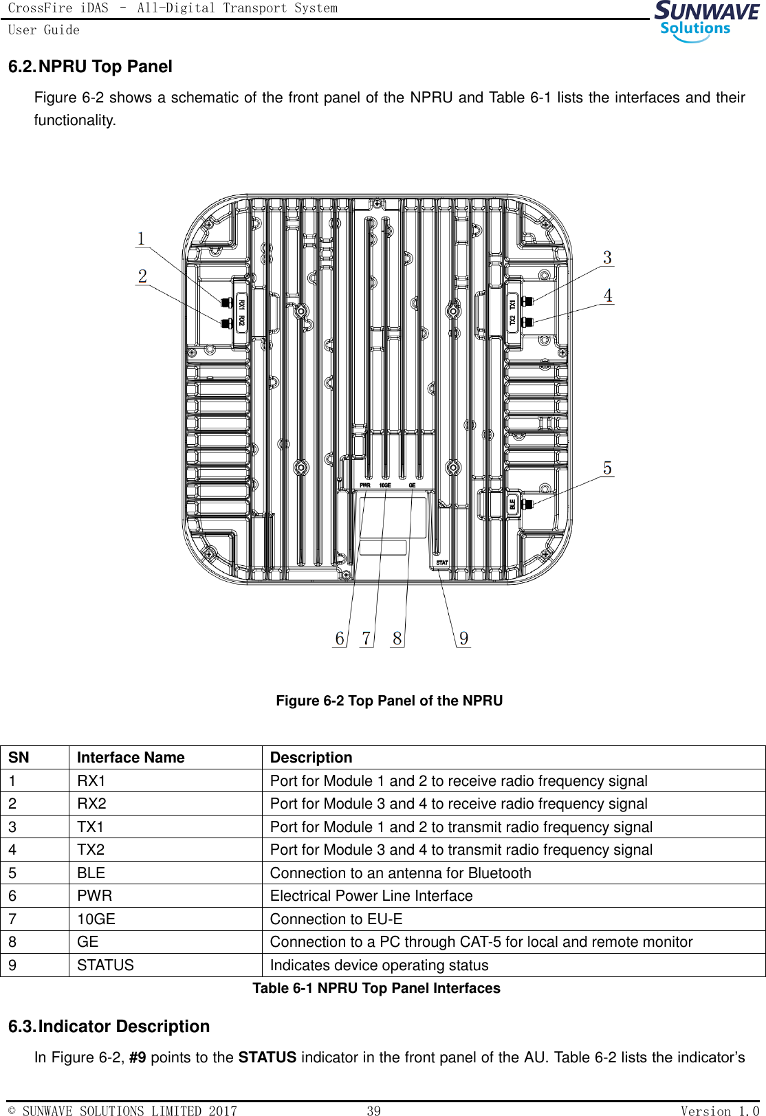
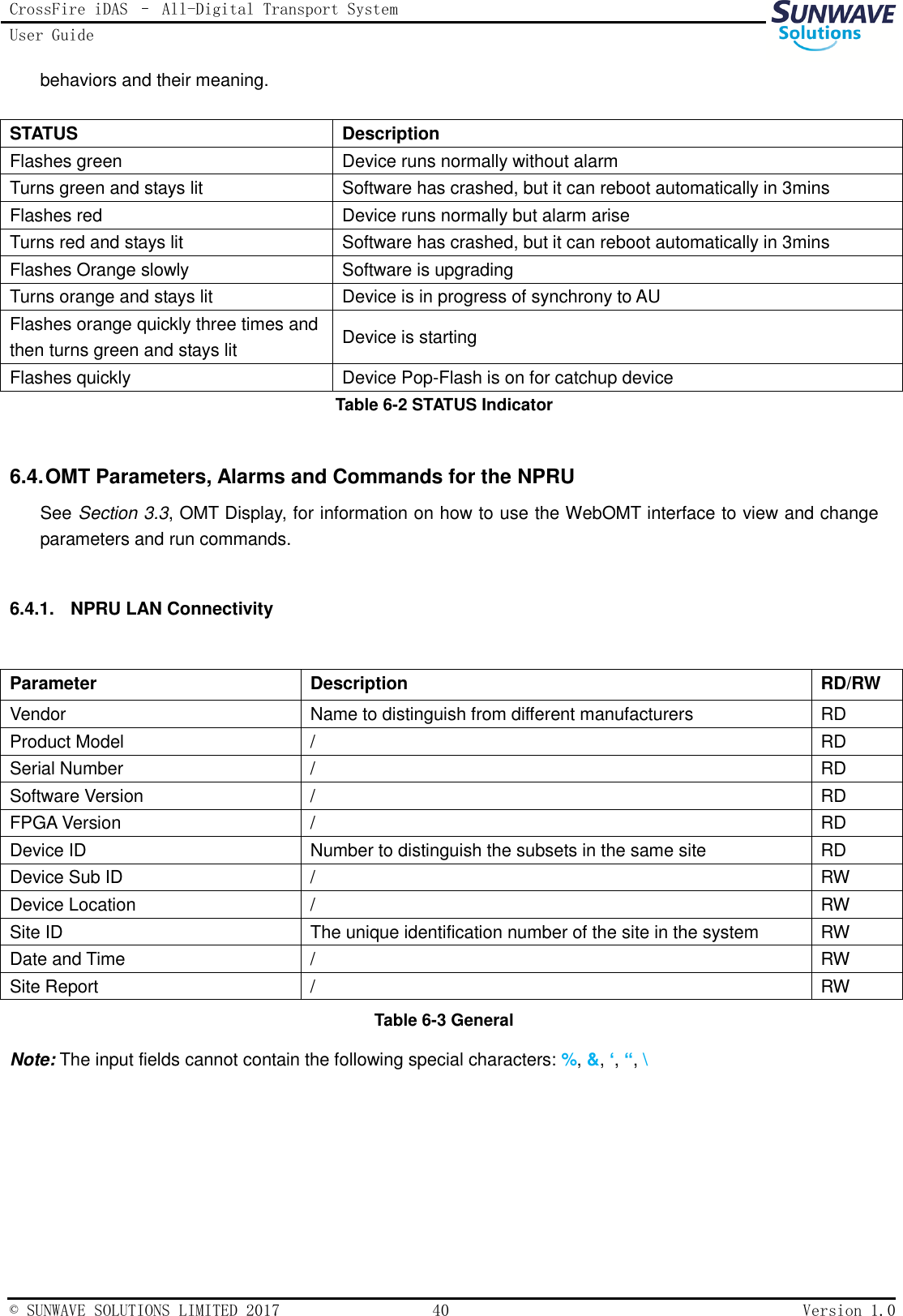
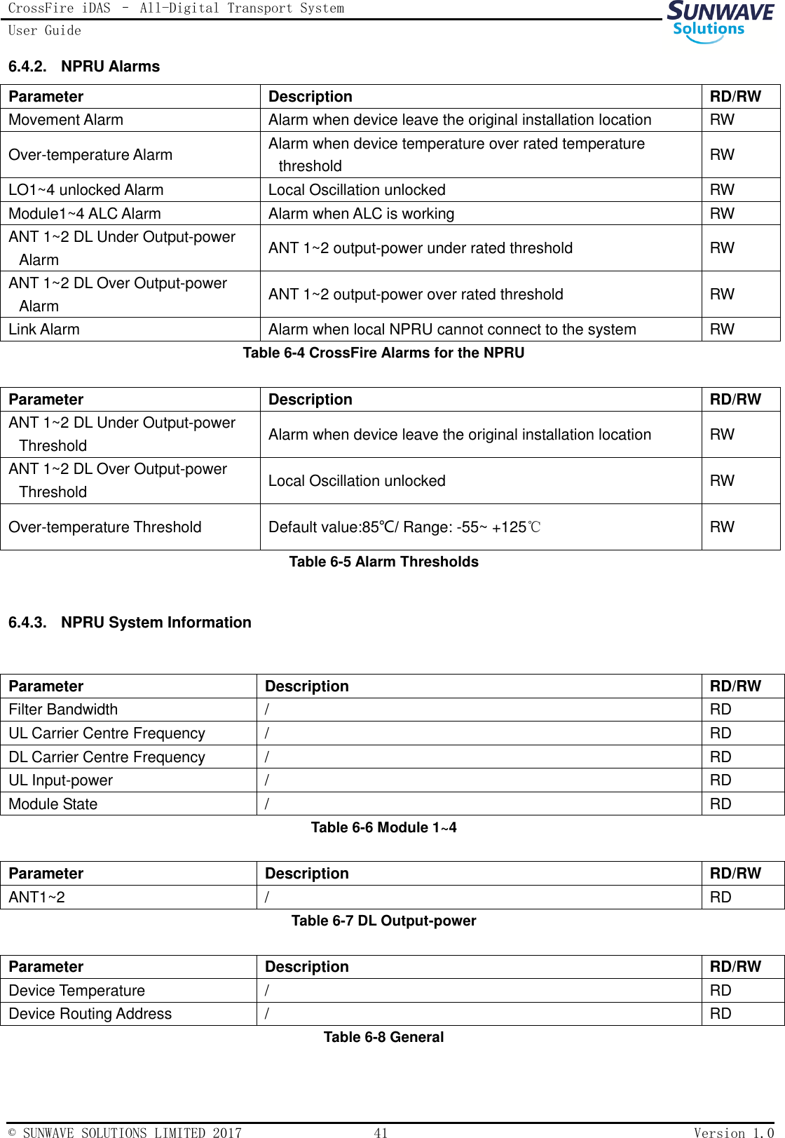
User manual - 1
Contents
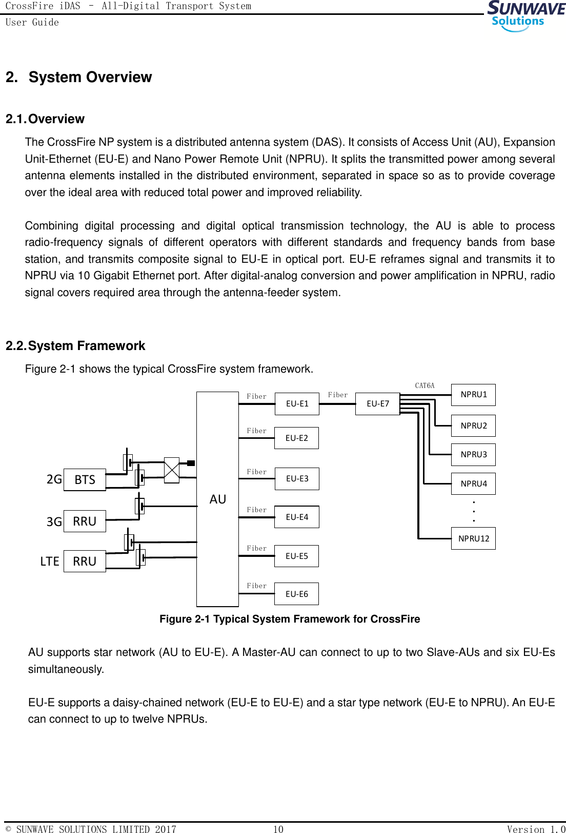
1.
User manual - 1
2.
User manual - 2
User manual - 1
Navigation menu
Upload a User Manual
Namespaces
Wiki Guide
HTML
PDF
Info
Views
User Manual
Discussion / Help
Navigation