Superior Electronics 135Q WIRELESS DRIVEWAY ALERT SYSTEM User Manual Manual
Superior Electronics Corporation WIRELESS DRIVEWAY ALERT SYSTEM Manual
Manual
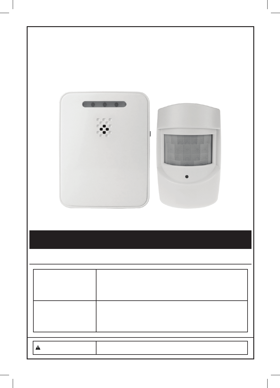
Wireless Alert
Person or Vehicle
Functional Description
Specifications
Sensor Module
Passive Infrared (PIR) motion detector
Transmitter: 433 MHz, range up to 120m (for open area)
Sensor Detection: 40° angle coverage at 8m, mounted at 1.2m high
Battery: 3 AAA batteries (not included)
Low battery LED indicator
Receiver Module
Range: Up to 120m (for open area) from Sensor Module
Battery: 3 C batteries (not included)
Power Switch with three settings: Off/Hi/ Low
Input connector for 6V DC Adapter (not included)
Low battery LED indicator
CAUTION To prevent injury: Wear ANSI-approved safety
goggles during installation. Read manual.
Page 2
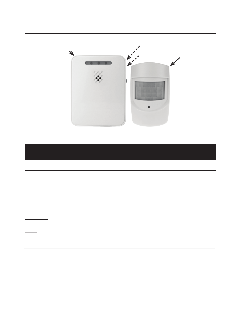
Sensor
Receiver
Power Switch
(On Side)
Figure A
DC Jack
(On Side)
Components and Controls
Setup Instructions
Installing Batteries
1. Using a screwdriver (not included),
remove the Battery Cover of the
Sensor, and insert three AAA
batteries (not included), positioning
in the correct polarity as indicated
in the battery compartment.
Replace the Battery Cover.
2. Using a screwdriver (not included),
remove the Battery Cover of
the Receiver, and insert three C
batteries (not included), positioning
in the correct polarity as indicated
in the battery compartment.
Replace the Battery Cover.
CAUTION: Position batteries in proper polarity and do not install batteries of different types,
charge levels, or capacities together.
Note: An optional 6 volt, 200 mA power adapter (not included)
can be used to power the Receiver instead of batteries.
Installing the Sensor and Receiver
Determine the location of the Sensor and Receiver. Choose locations
with no hidden wiring which would contact the mounting screws.
1. Considering the following when
choosing a location for the Sensor:
2. Using hardware (not included), mount
the Sensor securely to a flat surface.
3. Place the Receiver within
120m of the Sensor.
a. The passive infrared sensor detects
heat. Avoid aiming it towards
areas that produce heat such as
heater vents, windows where the
sun hits, or outdoor spotlights.
Note: Obstructions may reduce
the receiving range.

Page 3
b. Mount the Sensor at least 1m
above the ground. If placed under
the garage eaves, be sure that the
Sensor is not blocked by the roof
facia board.
c. If placed above 2m high,the Sensor
should be aimed downward so that
it is pointed toward the area being
monitored.
4. Mount the Receiver to a flat surface
with hardware (not included), or stand
on a flat surface. The receiver is not
intended to be weather resistant.
Note: Do not install the receiver in a
location that will get wet or directly
exposed to the elements.
Operation
Power Switch
The Power Switch has three settings:
a. Off: Power is off.
b. Low: A short beep will sound
(approximately 80dB) and the LED
will flash when motion is detected.
c. Hi: A loud beep will sound
(approximately 92dB) and the LED
d. Silent: No beep will sound and the LED
will flash when motion is detected.
will flash when motion is detected.
Operation
1. To operate the Driveway Alert, slide
the Power Switch on the Receiver
to the “Hi” setting. Allow 30 seconds
for warm-up. Two short beeps will
sound, indicating the unit is working.
2. Test the Sensor by walking or
driving into the protected area.
Another person should be listening
for the alarm to sound.
3. If the Sensor does not activate,
Sensor relocation or aiming
adjustment will be required.
4. If the Receiver does not activate with the
sensor, reposition them closer together.
5. Once you have determined that the unit
is working properly, leave in the “Hi”
setting, adjust to the “Low” setting or
adjust to the “Silent” setting.
Low Battery
1. When the Sensor batteries need
changing the LED on the Sensor
will turn on. Replace the batteries.
2. When the Receiver batteries
need changing, the center
LED on the Receiver will turn
on. Replace the batteries.
Cleaning Maintenance and Lubrication
1. BEFORE EACH USE, inspect the
general condition of the tool. Check for:
• leaking, swollen, or cracked batteries,
• loose hardware,
• misalignment or binding of parts,
• cracked or broken parts, and
• any other condition that may
affect its safe operation.
2. AFTER USE, wipe external surfaces
of the tool with clean cloth.
3. Replace the batteries in the
Receiver or Sensor when their low
battery LED indicator lights.
4. There are no replaceable parts on
the Receiver or Sensor units.

Page 4
Parts List
Part Description Qty
1 Transmitter 1
2 Receiver 1
Part Description Qty
3 Assembly Hardware 1
10. Do not overreach. Keep proper footing
and balance at all times. If a ladder
is to be used during installation, it
should be supported by an assistant.
11. Do not set up the Alert System
if under the influence of alcohol
or drugs. Read warning labels on
prescriptions to determine if your
judgement or reflexes are impaired
while taking drugs. If there is any
doubt, do not set up the Light.
13. The warnings, precautions, and
instructions discussed in this instruction
manual cannot cover all possible
conditions and situations that may
occur. It must be understood by the
operator that common sense and
caution are factors which cannot
be built into this product, but must
be supplied by the operator.
IMPORTANT SAFETY INFORMATION
1. Position batteries in proper polarity
and do not install batteries of
different types, charge levels,
or capacities together.
2. Keep installation area clean.
Cluttered areas invite accidents.
3. Observe installation area
conditions. Keep work area
well lit during installation.
4. Check for damaged parts. Before
using any product, any part that appears
damaged should be carefully checked
to determine that it will operate properly
and perform its intended function.
Check for any broken or damaged
parts and any other conditions that may
affect its operation. Replace or repair
damaged or worn parts immediately. Do
not use the Alert System if any switch
does not turn on and off properly.
5. Replacement parts and accessories.
When servicing, use only identical
replacement parts. Use of any
other parts will void the warranty.
6. Keep children away. Mount the Sensor
and Receiver out of children’s reach.
7. Dress properly. Protective,
electrically non-conductive
clothes and nonskid footwear are
recommended when working with
the Alert System. Wear restrictive
hair covering to contain long hair.
8. Use eye protection. Wear ANSI-
approved impact safety goggles
when setting up this product. 12. Have your power tool serviced by
a qualified repair person using
only identical replacement parts.
This will ensure that the safety of
the power tool is maintained.
9. Maintain products with care. Keep the
Alert System clean for better and safer
performance. Inspect the components
periodically. If damaged, have it
repaired by a qualified technician.

Page 5
The device complies with part 15 of the FCC Rules.
Operation is subject to the following two conditions:
(1) This device may not cause harmful interference.
(2) This device must accept any interference received, including interference that may cause
undesired operation.
Note : This equipment has been tested and found to comply with the limits for a Class B digital
device, pursuant to Part 15 of the FCC Rule. These limits are designed to provide
reasonable installation. This equipment generates, uses and can radiate radio frequency
energy and, if not installed and used in accordance with the instructions, may cause
harmful interference to radio communications.
However , there is no guarantee that interference will not occur in particular installation. If this
equipment does cause harmful interference to radio or television reception, which can be
determined by turning the correct the interference by one or more of the following measures:
Reorient or relocate the receiving antenna
Increase the separation between the equipment and receiver.
Connect the equipment into an outlet on a circuit different from that to which the receiver is
connected Consult the dealer or an experienced radio/TV technician for help.
Warning : Changes or modification to this unit not expressly approved by the part responsible for
compliance could void the use’s authority to operate the equipment.
This equipment complied with FCC radiation exposure limits set forth for an uncontrolled
environment. This equipment should be installed and operated with minimum distance 20cm
between the radiator and your body
Warnings
FCC Radiation Exposure Statement