SupplyNet Communications 1000 TANK MONITOR RF MODULE User Manual USERS MANUAL
SupplyNet Communications L.L.C. TANK MONITOR RF MODULE USERS MANUAL
USERS MANUAL

S
U P P L Y
N
E T
C O M M U N I C A T I O N S L . L . C .
Product Warranty and Notices – Chapter 9
Sentinel 2300 Series
/
Version 3.0 9/23/2004
Page 26
9-1 Product Warranty and Notices
SupplyNet Communications L.L.C. (“SupplyNet”) warrants that the equipment is and will
remain free from defects in workmanship and materials for a period of one (1) year from the
date of delivery.
Within the warranty period, SupplyNet shall, without charge for labor or materials, repair or
replace any defective components provided that reasonable care has been exercised in
protecting the equipment from adverse conditions and rough handling.
This warranty does not cover customer instruction, installation, set up adjustments, or signal
reception problems. This warranty does not cover cosmetic damage or damage due to acts of
God, accident, misuse, abuse, negligence, or modification of, or to any part of this
equipment, including the antenna. This warranty does not cover damage due to improper
operation or maintenance, connection to an improper voltage supply, or attempted repair by
anyone other than an authorized service facility. This warranty does not cover consumables
such as a fuse or battery.
This Limited Warranty is in lieu of all other warranties, express or implied (including
implied warranties of merchantability and fitness for a particular purpose), and of all
obligations or liabilities of SupplyNet for damages, including but not limited to consequential
and incidental damages, arising out of or in connection with the use or performance of the
equipment.
SupplyNet shall not be liable for any damages or loss arising from the use of the data from
this equipment or the TankLink.com web site.

S
U P P L Y
N
E T
C O M M U N I C A T I O N S L . L . C .
Terms and Conditions of Service – Chapter 8
Sentinel 2300 Series
/
Version 3.0 9/23/2004
Page 25
8-1 Terms and Conditions of Service
This section explains the relationship between the user of this equipment and SupplyNet
Communications L.L.C. It explains our respective legal rights concerning all aspects of our
relationship, including:
• Billing and extra charges
• Starting and ending service
• Privacy and confidentiality
• Early Termination fees ( if applicable )
• Limitations of liability and warranty
If you use the service or the equipment, or if you pay any amount billed to your account, you consent
to the terms and conditions set forth in this agreement. If you do not agree with these terms and
conditions, do not use the service and equipment and notify us immediately to cancel service.
1. Service
This is an agreement for Remote Data Delivery and associated Services between you and
SupplyNet Communications. The term "Unit" is the device which is used to communicate the
data to the SupplyNet Communications Data Center.
The term of this agreement depends on the rate plan which was defined in a separate document
which is also a part of this agreement. The term of this agreement begins on the date that we
activate Service for the Unit. There may be an activation fee associated with the rate plan that you
select. In addition, if you select a rate plan which requires a fixed term of more than one month (
such as a one-year plan ), you agree to purchase service for the full term. After the term expires,
or if there is not a fixed term associated with the service, then this agreement will continue in
force until terminated by either party with a 30-day notice. If you select a rate plan with a fixed
term of more than one month, you may terminate service within the first 30 days without a
penalty. If you terminate service after the initial 30 days but prior to the end of the term, or we
terminate following your default, you will be in material breach of this agreement and agree to
pay a cancellation fee as set forth in the rate plan document.
2. Rates
Your Service rates are described in your rate plan document. Your service rate may be based on
fees for data communication from your Unit and on fees for remote access to your data via the
internet or other electronic means. Additional fees may be added to your monthly fee for services
above your base rate. These additional fees and how they are calculated are described in your rate
plan document.
3. Data Availability and Service Interruptions
Wireless Data Transmission Service to the TankLink
®
data center is normally available to your
unit when it is within the coverage area of a Cellular Service provider who is under contract to
provide Microburst
®
Data Service. Service is subject to transmission limitation or interruption
caused by weather, terrain, obstructions such as trees or buildings, and other conditions. Service
may be limited in areas where Microburst
®
coverage is not available or may be temporarily
limited due to system capacity limits ( such as during peak usage periods ), system repairs, or
modifications. In addition, access to your information via the internet or other electronic means of
transmission may be temporarily limited due to system capacity limitations or maintenance.
Service interruption may also result from non-payment by you.
4. Use of Service/Unit
You agree not to use the unit or service for any unlawful purposes. You may not resell your
service without prior written contractual agreements with SupplyNet Communications

S
U P P L Y
N
E T
C O M M U N I C A T I O N S L . L . C .
Troubleshooting and Technical Support – Chapter 7
Sentinel 2300 Series
/
Version 3.0 9/23/2004
Page 24
7-4 Troubleshooting
There are no LEDs lit on the main board
! Check battery power.
Nothing happens when switches pressed.
! Check battery power.
Level reading is correct but volume is off.
! Verify the tank capacity. This should be the volume in the tank at the tank height. If
the tank has a slight cone top but a standard vertical strapping chart is used, then the
tank height should be only to the shoulder of the tank.
! Verify that the correct strapping chart is used.
Unit cannot transmit to data center.
! Verify the signal strength with a spare radio.
! Check for interfering structures.
! Reposition unit if possible.
! Check that the antenna cable connection to the radio is tight.
! Verify the Network Number of the unit and the setting on the Base Station.
7-5 Obtaining Technical Support
If you still are having trouble, contact SupplyNet Communications Technical support
hotline at 1-888-TANKLINK.
You will need the following information:
• Sentinel Serial Number (label on the circuit board with the numbers 175830xxxx)
• Tank location (city/state).
• Tank product
remember:
For security reasons, no one from SupplyNet Communications will ever ask you for
your logon or password.
If it should be necessary to return this unit to SupplyNet Communications for service:
1) You must first obtain a Return Authorization Number from SupplyNet
Communications.
2) This number must be clearly marked on the outside of the shipping container and on
the service card which was supplied with the unit.
3) Place the unit with the service card in the original container and ship it prepaid to the
address on the service card.

S
U P P L Y
N
E T
C O M M U N I C A T I O N S L . L . C .
Troubleshooting and Technical Support – Chapter 7
Sentinel 2300 Series
/
Version 3.0 9/23/2004
Page 23
7-3 Battery Pack Replacement
The tank monitor that is installed on your bulk storage tank is fitted with an easily
replaceable battery pack. The procedure below outlines the steps necessary to change a dead
battery pack.
1. Secure a ladder to the bulk tank that has the Sentinel tank monitor with the dead
battery pack.
2. With one hand, grab hold of the Sentinel tank monitor. With your free hand,
carefully unscrew the black plastic top.
3. Locate the battery pack inside the monitor. Unplug the orange two-pin connector,
and remove the battery pack.
4. Holding the monitor firmly with one hand, insert the new battery pack into the
monitor, and connect the new battery pack into the orange two-pin connector.
5. Locate the Sentinel’s black antenna, and insure that it is tightly connected to the
monitor, and is pointing straight up.
6. With the cover still removed, locate the small white pushbutton located near the top
right corner of the monitor’s circuit board (opposite side of the orange two-pin
connector; refer to illustration below).
7. Press and hold the little white button until a green LED lights up. The green LED
will flash fast (half second ON, half second OFF).
8. Upon establishing a link with the Base Station, the green LED will flash slow (one
second ON, one second OFF).
9. When a command is received from the Base Station, the green LED will go to solid
ON for about 10 seconds. This is the actual transmission of data to the SupplyNet
Base Station.
10. After a successful transmission, the green LED will flash once ON and OFF, then
extinguish. The Sentinel is now in passive mode, and will remain in passive mode
until the next scheduled transmission time, or when the little white button is pressed
and held again.
11. If the data transmission was not successful, a red LED will flash once, followed by
up to ten green LED flashes. The number of green LED flashes following the red
LED flash corresponds to an error code. Please note the number of green flashes.
12. Note the time the LED went to solid ON (the actual data transmission). Contact the
SupplyNet Monitoring Center at 888-826-5546, ext. 713 to verify a successful data
transmission, and to verify the product level, so we can insure the monitor is working
properly.
13. Replace the black plastic to onto the Sentinel finger tight.
14. Congratulations!! You have successfully replaced a dead battery pack.
S
U P P L Y
N
E T
C O M M U N I C A T I O N S L . L . C .
Troubleshooting and Technical Support – Chapter 7
Sentinel 2300 Series
/
Version 3.0 9/23/2004
Page 22
Jumper J2 Used together with jumper J4 to determine the number
of data transmissions per 24 hour period.
Jumper J3
OFF = default setting. Keeps the Sentinel active for
20 seconds to complete the measurement.
ON = keeps Sentinel active for an extended period of
time (60 seconds). Used to accommodate
some external sensors which require additional
time to complete the measurement.
Jumper J4 Used together with jumper J2 to determine the number
of data transmissions per 24 hour period.
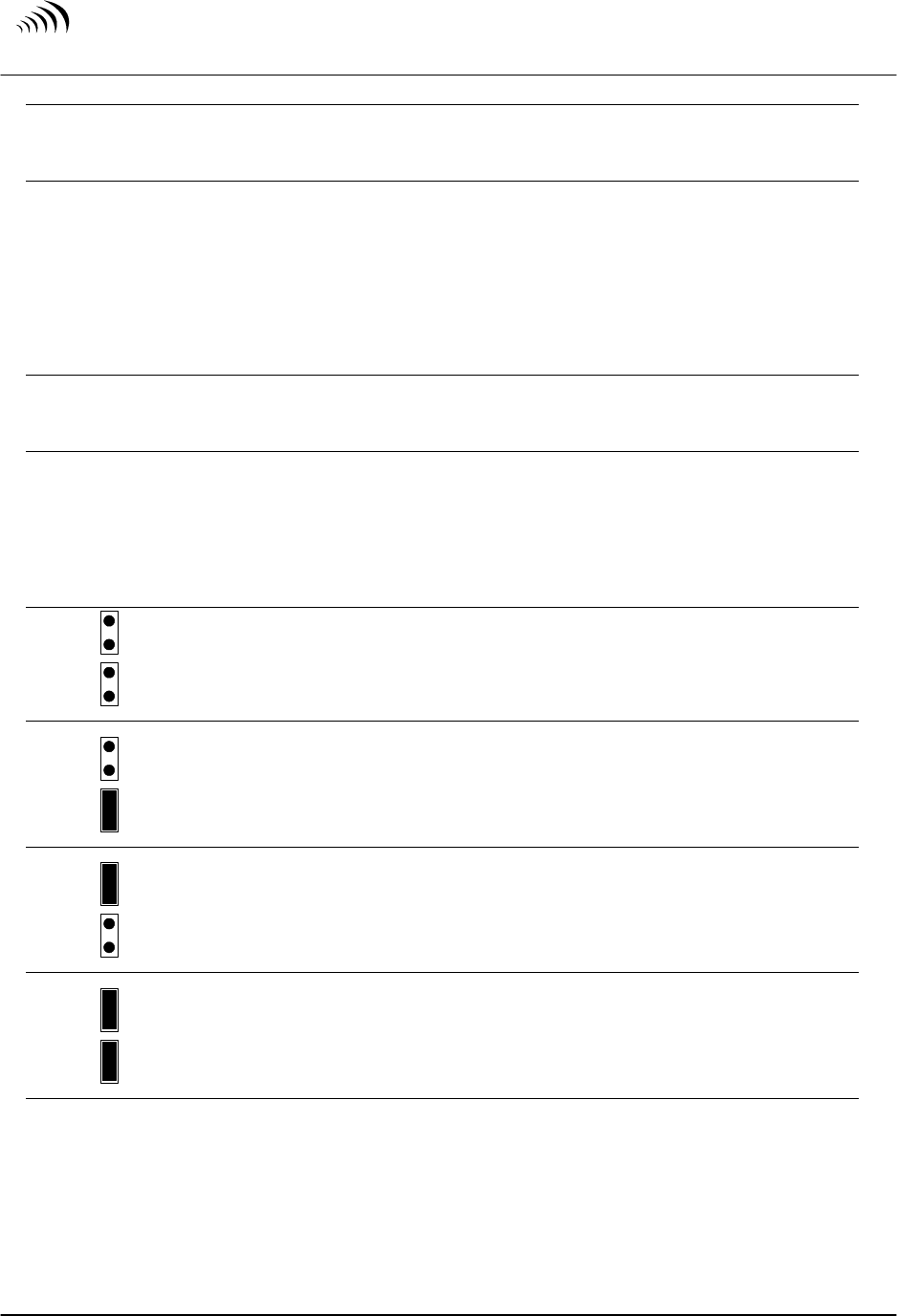
Jumpers J2 and J4 are used together to determine the number of data transmissions per 24
hour period. The table below illustrates the four combinations possible:
J2
J4
OFF
OFF
One data transmission per 24 hours.
J2
J4
OFF
ON
One data transmission per 24 hours, plus data transmission upon a
10% change in product level. This option requires upgraded
software in the Sentinel.
J2
J4
ON
OFF
Three data transmissions per 24 hours.
J2
J4
ON
ON
One data transmission every hour. (for factory testing only)

S
U P P L Y
N
E T
C O M M U N I C A T I O N S L . L . C .
Troubleshooting and Technical Support – Chapter 7
Sentinel 2300 Series
/
Version 3.0 9/23/2004
Page 21
7-1 Error Codes
If the data transmission was not successful from a Sentinel, a red LED will flash once,
followed by up to ten green LED flashes. The number of green LED flashes following
the red LED flash corresponds to the error code.
Number of
Green Flashes
Error Code Description
1
Internal Clock Error
Sentinel could not initialize properly due to a failure of the internal
clock. If this problem continues, replace the Sentinel unit.
2
Low Battery Voltage
Sentinel could not transmit due to a low battery voltage. Replace the
battery and re-try data transmission.
3
Radio Error
The Sentinel’s wireless transmitter did not power on properly. If this
problem continues, replace the Sentinel unit.
4 Link Error
No link was established with the Base Station
5 Command Error
No command received from the Base Station.
6
Radio Respond Error
The Sentinel’s wireless transmitter did not respond for the command to
transmit data. If this problem continues, replace the Sentinel unit.
7 Unused
8
Failed Transmission Error
The data transmission failed. Re-try data transmission. If this problem
continues, replace the Sentinel unit.
9
Radio Error
The Sentinel’s wireless transmitter did not initialize properly. If this
problem continues, replace the Sentinel unit.
10
Radio Memory Error
The Sentinel’s wireless transmitter’s memory has been corrupted. If
this problem continues, replace the Sentinel unit.
7-2 Jumper Settings
There are four jumpers located in the Sentinel (J1 thru J4). Below are the descriptions:
Jumper J1 ON = channel 0 data communications
OFF = channel 1 data communications

S
U P P L Y
N
E T
C O M M U N I C A T I O N S L . L . C .
Specifications – Chapter 6
Sentinel 2300 Series
/
Version 3.0 9/23/2004
Page 20
6-1 Sentinel Specifications
Performance Specifications:
Output Voltage Nominally 24V ± 5%
Output Current Rated from 0 – 24 mA
Load Regulation 0.5% from a 24 mA load
Ripple 50 mV peak-to-peak
DC Isolation 100 MΩ with 200 VDC applied between output and
case, input to case, and input and output
Output Short Circuit Protection Output is current limited to 24 mA
Accuracy ± 1% of Span
Hardware Specifications:
Differential Pressure Sensor SS316; 1 inch (25 mm) OD x 3 inch (76 mm) length;
0-30 psi (0-2.1 kg/cm2) operating range for 34 ft (10.3
meter) cable; 7.5 psi (0-0.53 kg/cm2) for 17 ft (5.1
meter) cable.
Ultrasonic Sensor pvdf Kynar construction exposed to wetted portion of
the tank.
Housing NEMA 4X; weatherproof; UL approved (UL94V0);
polyproprolene construction
Area Classification General Purpose environment
Unit Gross Weight With Ultrasonic Level Sensor: 2.0 lbs (0.91 kg)
With 7.5 psi range Submersible Differential Pressure
Sensor: 2.1 lbs (0.95 kg)
With 30 psi range Submersible Differential Pressure
Sensor: 2.6 lbs (1.18 kg)
Battery:
Type Replaceable Lithium-Ion Battery Pack
Expected Battery Life One call out per day – replacement up to 60 months
Three call outs per day – replacement up to 48 months
Environment:
Ambient Temperature Range -20û to 160ûF (-28û to 71ûC)
Antenna Connector
Type Standard SMA

S
U P P L Y
N
E T
C O M M U N I C A T I O N S L . L . C .
Viewing your Data on the Internet – Chapter 5
Sentinel 2300 Series
/
Version 3.0 9/23/2004
Page 19
The real power behind the TankLink
®
Inventory management system is the TankLink.com
web site. On this web site, you may view the current level and status of your devices using a
standard web browser (ie. Microsoft Internet Explorer
®
or Netscape Navigator
®
), download
your historical data to applications such as Microsoft Excel
®
, or set up alarm levels to
automatically trigger events such as an e-mail or page to a local service or sales
representative. On this web site you may also check to see if Microburst
®
service is available
in any area of the country. The TankLink.com web site is a secure web site which utilizes
the latest in internet encryption technology to ensure that your data stays confidential. It is
constantly being upgraded and new features are being added periodically. To obtain the
latest details on how to use the new features of the web site, follow the links to the help
section of the web site.
5-1 Accessing the TankLink.com Web site
The TankLink.com web site may be accessed from any computer with internet access by
going to the following URL:
http://www.tanklink.com
This will bring you to the SupplyNet Communications home page. Follow the links to
the Web Data Retrieval system. This will take you to the Logon page.
To view your data on the web you must first have a Logon and Password. A Logon and
Password will be provided to you or to your representative when the service agreement
with SupplyNet Communications is finalized. If you have forgotten your logon or
password or need a new one, please contact the SupplyNet Technical Support at 1-888-
TANKLINK.
Once a valid logon and password have been entered, you may select which tanks to view.
Tanks may be viewed by geographical location, product type, region, etc. Once the tank
levels are viewed, detailed information for each tank may be viewed, edited, or the
historical data for the tank may be viewed.
When a unit is sold by SupplyNet Communications, a default tank entry is set up on the
web site and it is assigned to the logon. When the unit is installed, the pertinent
information will need to be set up on the web site by the customer. This includes: Tank
Name, Product type, Tank Location, Contact information, etc.

S
U P P L Y
N
E T
C O M M U N I C A T I O N S L . L . C .
Unit Operation – Chapter 4
Sentinel 2300 Series
/
Version 3.0 9/23/2004
Page 18
4-1 Final Testing
Once all tank preparation has been completed, the Sentinel is properly mounted to the
tank, the signal strength has been verified and the number of callouts per day has been
properly set, it is now time to establish communications with the SupplyNet Monitoring
Center.
1) With the top black cover of the Sentinel removed, plug in the replaceable battery
pack into the orange two-pin connector.
2) Locate the little white button which is mounted to the right of the orange two-pin
battery connector.
3) Verify the Sentinel’s antenna is pointing straight up.
4) Press and hold the little white button until a green LED lights up.
5) The green LED will flash fast (half second ON, half second OFF).
6) Upon establishing the link, the green LED will flash slow (one second ON, one
second OFF).
7) When ready to transmit, the green LED will go to solid ON for about 10 seconds.
This is the actual transmission of data to the Base Station.
8) After a successful transmission, the green LED will extinguish. The Sentinel is now
in passive mode, and will remain in passive mode until the next scheduled
transmission time (determined by Jumpers J2 & J4 – Number of Callouts per Day), or
when the little white button is pressed and held again.
9) If the data transmission was not successful, a red LED will flash once, followed by
up to ten green LED flashes. The number of green LED flashes following the red
LED flash corresponds to an error code. Refer to Section 7-1 of this manual for
information on the error code.
10) Note the time the LED went to solid ON (the actual data transmission). Contact the
SupplyNet Monitoring Center at 888-826-5546, ext. 713 to verify a successful data
transmission from the Base Station, and to verify tank information.
11) Replace the black cover onto the Sentinel finger tight.
4-2 Normal Operation
After communication has been established, and the tank information has been given to
the SupplyNet Monitoring Center, the Sentinel will continue to transmit data based upon
the number of callouts per day set.
This tank data can be accessed thru the internet. Refer to Chapter 5 of this manual for
information on accessing this data.
S
U P P L Y
N
E T
C O M M U N I C A T I O N S L . L . C .
Communications Setup – Chapter 3
Sentinel 2300 Series
/
Version 3.0 9/23/2004
Page 17
J2
J4
ON
OFF
Three data transmissions per 24 hours.
J2
J4
ON
ON
One data transmission every hour.
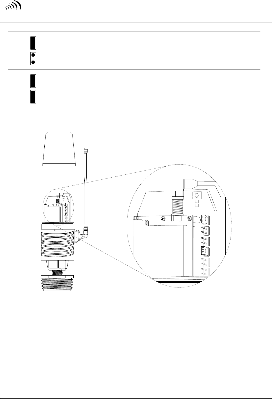
Figure 9 illustrates the location of Jumpers J2 and J4.
T a n k L i n k
S e n t i n e l
D 3
D 4
D 3
D 4
J 1
J 2
J 3
J 4
J 1
J 2
J 3
J 4
Figure 9
Jumper Locations

S
U P P L Y
N
E T
C O M M U N I C A T I O N S L . L . C .
Communications Setup – Chapter 3
Sentinel 2300 Series
/
Version 3.0 9/23/2004
Page 16
“link” light. This light stays on whenever a link has been established with the Base
Station. Failure to see the link light illuminate indicates a poor signal which does not
allow the radio to establish a connection. Make several transmissions when determing the
signal strength observing the link light each time.
3-3 Remote Tank Unit ID
Each Sentinel has a unique embedded RTUID number. This number is printed on the
label found on the outside of the body of the Sentinel. For proper communication this
number must match the RTUID setting for the tank that is setup in the Base Station.
Failure to do this will result in an error message displayed on the Base Station. This
message is as follows: “MESSAGE FROM UNKNOWN RUTID”.
3-4 Setting the Number of Callouts per Day
The Sentinel can be jumper set to transmit the current data once every 8 hours, or once
every 24 hours. The first callout is set when the white button is pressed for a forced
transmission.
For instance:
The white button is pressed during commissioning at 9:00 am. For a transmission every
24 hours, an automatic reading will be transmitted every day at 9:00 am. For a
transmission every 8 hours, the reading will be transmitted at 9:00 am, 5:00 pm, and 1:00
am.
CAUTION:
If you set the number of calls to a number greater than the number of calls included in
your service agreement, then an additional fee will be charged for each call above
your allotment.
Jumpers J2 and J4 within the Sentinel control the number of callouts. The table below
describes the four possible combinations:
J2
J4
OFF
OFF
One data transmission per 24 hours.
J2
J4
OFF
ON
One data transmission per 24 hours, plus data transmission upon a
10% change in product level.
S
U P P L Y
N
E T
C O M M U N I C A T I O N S L . L . C .
Communications Setup – Chapter 3
Sentinel 2300 Series
/
Version 3.0 9/23/2004
Page 15
3-1 Setting the Network Address
Jumper J1 inside the Sentinel is used to select the network address. The address assigns a
group of Sentinels to a given Base Station. Generally we use only one Base Station.
Therefore, by default channel 1 is used and this must match the number set in the Base
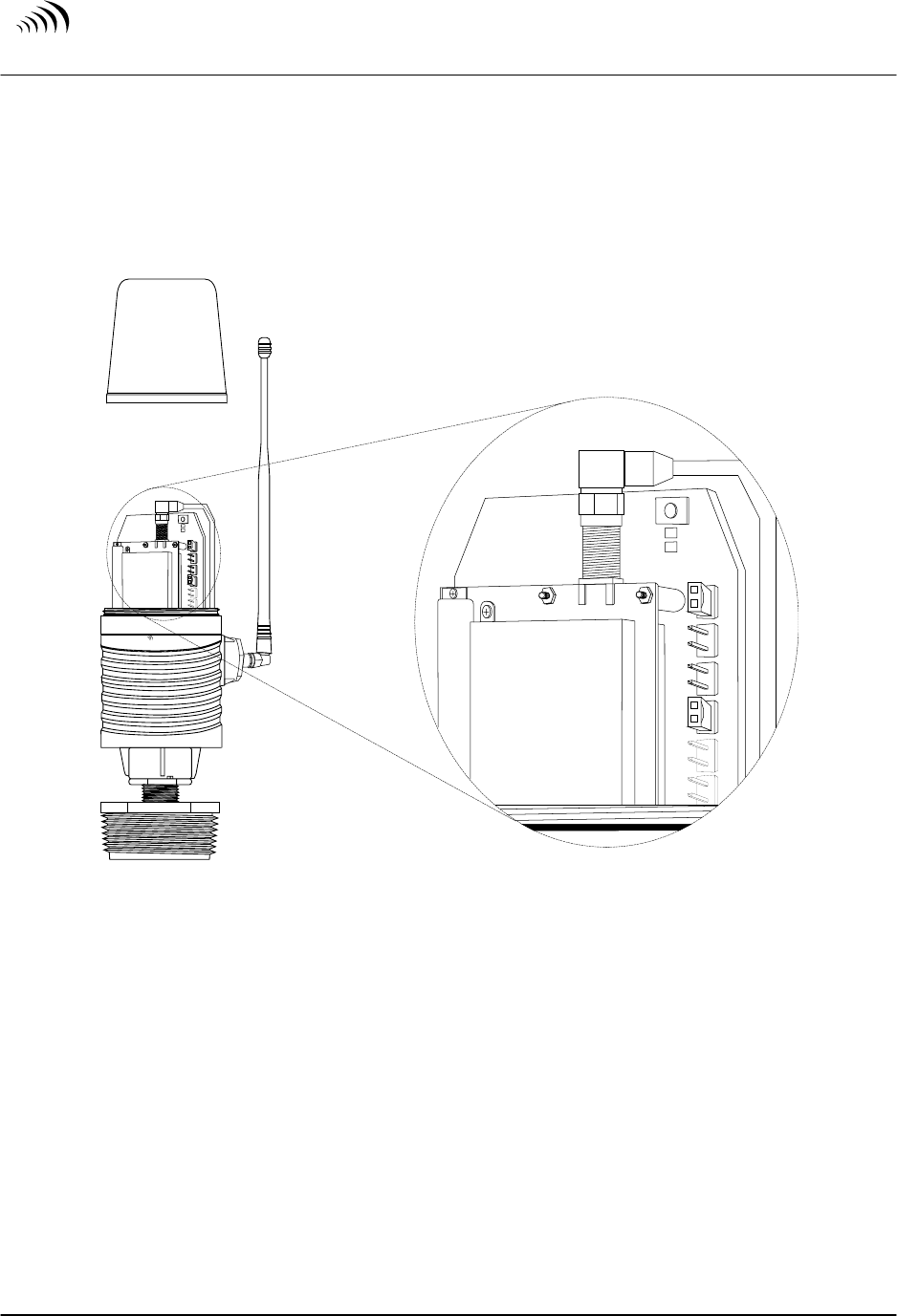
Station. Figure 8 illustrates the location of Jumper J1.
T a n k L i n k
S e n t i n e l
D 3
D 4
D 3
D 4
J 1
J 2
J 3
J 4
J 1
J 2
J 3
J 4
Figure 8
Cellular Carrier Selection
Jumper J1 in the OFF position (jumper removed, or positioned onto one pin only) selects
channel 1. Jumper J1 in the ON position (across the first two pins) selects channel 2.
3-2 Determining the Signal Strength
During installation, the strength of the signal from the Base Station should be determined
using the LEDs on the transmitter board in the Sentinel. Pressing the start button and
holding it for two seconds, look for the green light to begin flashing at the top of the
main board. In approximately 30 seconds the transmitter power will come on as indicated
by the red light at the bottom of the radio board. At the same time the row of lights in the
middle of the board will flash in sequence indicating a proper start up of the radio. The
end light flashes continuously and is normal. The light at the other end of the row is the
S
U P P L Y
N
E T
C O M M U N I C A T I O N S L . L . C .
Installation – Chapter 2
Sentinel 2300 Series
/
Version 3.0 9/23/2004
Page 14
2-7 Tank Measurements
Accurate tank measurements are required to properly complete the installation process.
The Sentinel can easily determine the product level, however, accurate tank dimensions
are required to convert a measured product level into a calculated product volume.
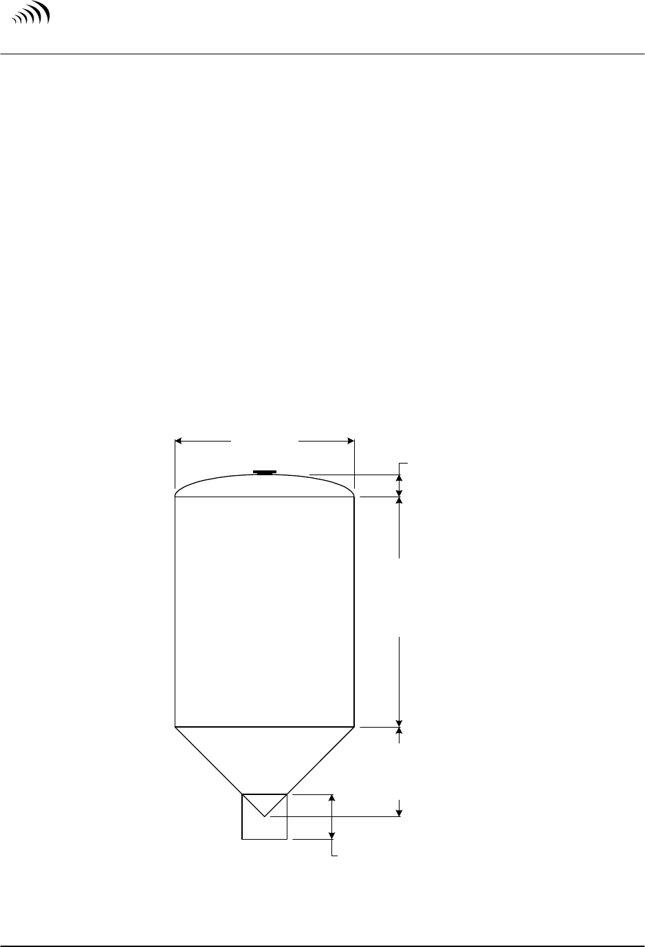
Figure 7 illustrates tank terminology used for the calculation of the capacity of the tank.
Tank capacity is typically the tank volume up to the “Top Tangent Line”. Any dome or
dish on the top of the tank is not included in the capacity determination.
The orientation of the tank below the “Bottom Tangent Line” can greatly affect the
product volume calculation. The distance below the bottom tangent line is measured by
first measuring the distance from the bottom tangent line to the ground, then subtracting
the distance from the ground to the absolute bottom of the tank.
Some tanks have a small cube “Box” at the very bottom of the tank, typically at the
bottom of a cone. This box can be easily measured and depending on the size of the box,
can affect product volume calculation.
Tank
Diameter
Tangent
to
Tangent
Height
Bottom
Cone
Height
Top
Dome
Height
Box
Dimensions
Figure 7
Typical Tank Measurements
S
U P P L Y
N
E T
C O M M U N I C A T I O N S L . L . C .
Installation – Chapter 2
Sentinel 2300 Series
/
Version 3.0 9/23/2004
Page 13
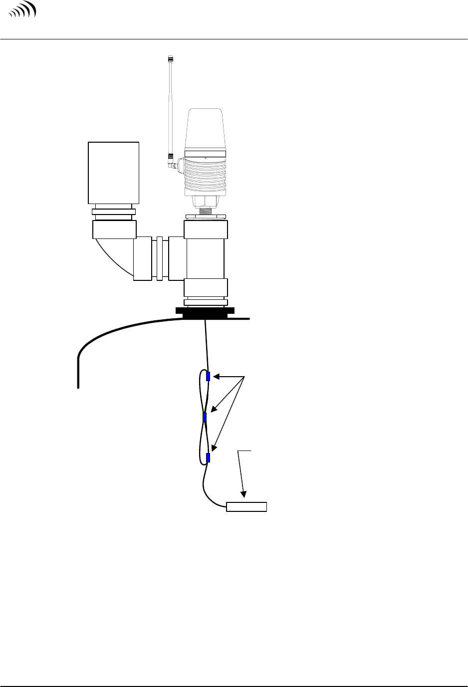
TankLink
Sentinel
Vent
Three Plastic or non-metalic
Ties are used to secure
excess cable into a loop
Sensor should just rest on
the tank bottom, but not
enough to allow the sensor
into the discharge piping
Figure 6
Pressure Differential Sentinel Installation

S
U P P L Y
N
E T
C O M M U N I C A T I O N S L . L . C .
Installation – Chapter 2
Sentinel 2300 Series
/
Version 3.0 9/23/2004
Page 12
2-6 Mounting the Unit (Pressure Differential)
Pressure Differential Sentinels operate by measuring the pressure (weight) of the liquid
the sensor is submerged into.
The opening on the end of the sensor contains an exposed diaphragm which responds to
changes in liquid pressure as the tank is filled or emptied with product. This measured
pressure is compared against atmospheric pressure, and is converted to a readable signal
by a microprocessor in the Sentinel.
Please note that the sensor and sensor cable must be clean when installed, to avoid
contamination of the contents of the tank. These tanks are inspected for product
contamination, and the Sentinel installation cannot compromise the product in the tank.
Care must be taken before and during installation to not strike the sensor against any
stationary surface. This can frequently occur during installation of the probe into the
tank. Shock may damage the probe causing it to fail prematurely.
Ensure the probe can reach the bottom of the tank.
CAUTION:
Typically there will be more cable than what is required for the sensor to reach the
bottom of the tank. This “slack” cable must be taken care of during the installation.
The slack must be looped and secured using typically three plastic or non-metalic
ties, so the loop will not come apart. A correct installation will result in the sensor
just slightly resting at the bottom of the tank, with all excess slack secured in the
loop. There should not be enough excess cable for the sensor to enter into the
discharge piping. Refer to Figure 6.
Verify the sensor and cable slack loop can pass thru all plumbing without having to
disassemble the plumbing. Ensure the threads at the Sentinel mounting point have not
been compromised. The Differential Pressure Sentinel is now ready to be placed into
service.
S
U P P L Y
N
E T
C O M M U N I C A T I O N S L . L . C .
Installation – Chapter 2
Sentinel 2300 Series
/
Version 3.0 9/23/2004
Page 11
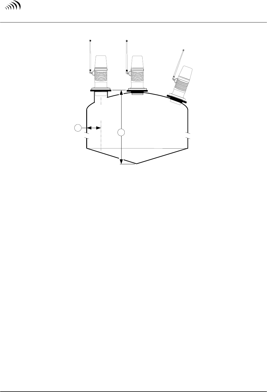
"C"
BAD
"B"
GOOD
"A"
BAD
12
Figure 5
Ultrasonic Sentinel Installations
“A” is NOT a good installation, since the bung opening is less than 1/3 the tank diameter
away from the edge of the tank. In this example, a Differential Pressure Sentinel will
have to be used instead of the Ultrasonic Sentinel.
“B” is a GOOD installation. The bottom of the Sentinel is into the tank, and the Sentinel
is mounted plumb and close to the center of the tank.
“C” is NOT a good installation, since the Sentinel cannot be mounted plumb. In this type
of installation, the ultrasonic signal will not bounce directly from the product back to the
sensor, but will instead bounce around the inside of the tank, causing inaccurate or even
no reading. In this example, a Differential Pressure Sentinel will have to be used instead
of the Ultrasonic Sentinel.
Note: For installation geometry other than those shown, contact SupplyNet
Communications. An Extended Length Ultrasonic sensor may be an
alternative option.
Once the bung opening is verified to be a good Ultrasonic installation, ensure the bung
threads have not been compromised. The Ultrasonic Sentinel is now ready to be placed
into service.
S
U P P L Y
N
E T
C O M M U N I C A T I O N S L . L . C .
Installation – Chapter 2
Sentinel 2300 Series
/
Version 3.0 9/23/2004
Page 10
2-5 Mounting the Unit (Ultrasonic)
Ultrasonic Sentinels operate using sound wave technology, which pulses sound waves
from the bottom of the Sentinel downward into the tank. A microprocessor times how
long the sound wave takes to bounce off the liquid level in the tank and return to the
Sentinel.
The transmitting and receiving of the sound waves take place from the bottom of the
Sentinel. Therefore, the location of the Sentinel bottom in relation to the opening of the
tank is critical.
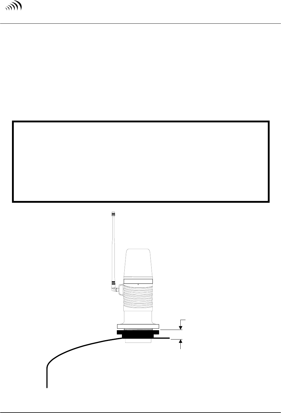
CAUTION:
The bung opening must be plumb in reference to the overall tank.
The distance from the top of the bung opening to the inside surface of the tank can be
no greater than 1.0 inch. Refer to Figure 4.
The bung opening must be at least 1/3 the overall tank diameter away from the tank
edge. For example, if the tank diameter is 90 inches, the bung opening must be at
least 30 inches from the tank edge. Refer to dimension 1 of Figure 5.
The distance from the top of the bung opening to the very bottom of the tank can be
no greater than 144 inches. Refer to dimension 2 of Figure 5.
Ta nkLink
Sentinel
Maximum
Distance =
1.0 inches
Figure 4
Ultrasonic Sentinel Bung Distance
S
U P P L Y
N
E T
C O M M U N I C A T I O N S L . L . C .
Installation – Chapter 2
Sentinel 2300 Series
/
Version 3.0 9/23/2004
Page 9
2-4 Poly Tank Preparation
Please check the following before installation of the Sentinel:
• A 2 inch diameter threaded opening is required for the installation of a Sentinel. If the
tank does not have a threaded opening available, a hole must be cut into the top of the
tank. Refer to the procedure below for the installing a plastic bung kit.
• For Differential Pressure Sentinel installations, verify if a mechanical agitation device
exists within the tank, which could damage the sensor.
• For Ultrasonic Sentinel installations, verify no obstructions exist within the tank which
could alter the ultrasonic readings.
Installing a Plastic Bung Kit
The following tools are required to complete this procedure:
Plastic bag for catching debris
Duct tape
Drill with a 3-inch holesaw bit
2 inch Plastic Bung Kit
1) Open the manway at the top of the tank.
2) Open the plastic bag and secure the opening to the approximate center where the hole
will be drilled. The bag will catch any debris created by the holesaw while drilling
the bunghole.
3) Using the drill and 3-inch holesaw bit, drill thru the plastic tank.
4) Once the hole is cut, remove the garbage bag. Use care in removing the bag and duct
tape off the inside surface of the tank.
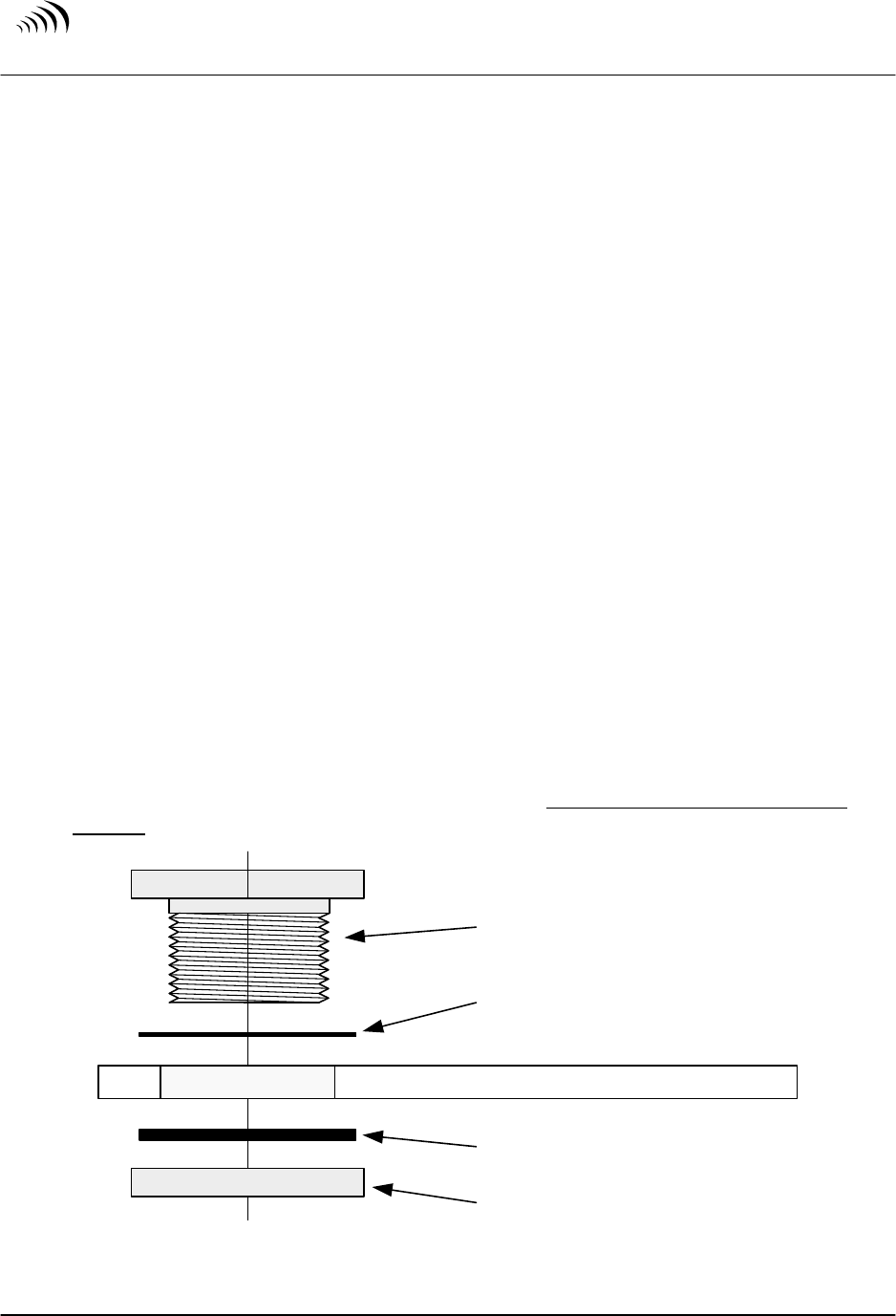
5) The 2 inch Plastic Bung Kit may now be installed. The Bung need only be tightened
by hand. Refer to Figure 3 for proper assembly.
Tank Bung
(typically left hand threads)
Poly Tank with 3 inch hole cut thru
Rubber Gasket
Plastic Washer
Plastic Bung Nut
Figure 3
Plastic Bung Kit Installation
S
U P P L Y
N
E T
C O M M U N I C A T I O N S L . L . C .
Installation – Chapter 2
Sentinel 2300 Series
/
Version 3.0 9/23/2004
Page 8
2-3 Stainless Steel Tank Preparation
Please check the following before installation of the Sentinel:
• A 2-inch diameter threaded opening is required for the installation of a Sentinel.
Stainless Steel tanks are typically built with one or more 2-inch threaded “bung”
opening. The tank’s vent line can be modified to provide both tank venting and access
for the Sentinel, if the vent is the only 2-inch threaded opening available. Refer to the
procedure below for the installation into a vent line.
• For Differential Pressure Sentinel installations, verify if a mechanical agitation device
exists within the tank, which could damage the sensor.
• For Ultrasonic Sentinel installations, verify no obstructions exist within the tank which
could alter the ultrasonic readings.
Installation into a Vent Line
Note: The following procedure can only be used with a Pressure Differential
Sentinel. Ultrasonic Sentinel’s must be installed directly into a bung opening.
The following tools are required to complete this procedure:
Two Pipe Wrenches
2-inch Vent Kit consisting of either non-metallic or Stainless Steel material
• one 2-inch Tee
• one 2-inch 90 Elbow
• two 2-inch Close Nipple
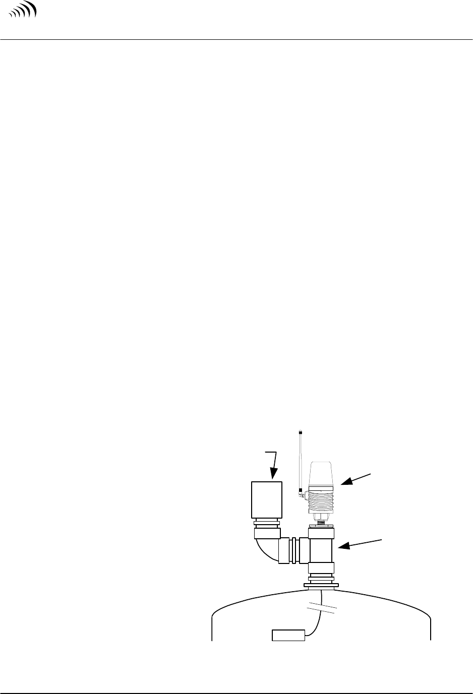
1) Using the two pipe
wrenches, remove the
existing vent assembly
from the top of the tank.
2) Assemble the Vent Kit
items in the manner
shown in Figure 2.
3) Install the existing vent
assembly onto the 90
Elbow as shown in Figure
2.
4) Install the Differential
Pressure Sentinel onto the
top of the Tee as shown
in Figure 2.
TankLink
Sentinel
Differential
Pressure
Sentinel
Vent
Kit
Existing
Vent
Assembly
Figure 2
Vent Kit Installation

S
U P P L Y
N
E T
C O M M U N I C A T I O N S L . L . C .
Installation – Chapter 2
Sentinel 2300 Series
/
Version 3.0 9/23/2004
Page 7
2-1 Safety Precautions
The Sentinel
™
uses Radio Frequency (RF) waves for communication to the nearest Base
Station. In general, the Sentinel should be able to communicate properly if you are within
1000 feet of the Base Station. However, because of the inherent characteristics of RF
communications, there are certain guidelines that should be followed when positioning
the unit.
Warning !
• Do not use the Sentinel
™
in hospitals or near medical equipment.
• Do not install the Sentinel
™
where hazardous vapors are present.
• Do not use the Sentinel
™
where blasting is in progress.
• Electrostatic discharge can damage sensitive electronic components. Be sure to touch
a grounded object before working on the internal circuit board.
• The unit should be located in an area free from overhanging metal structures, large
obstructions, or equipment which could generate RF or electrical interference.
• If you have doubt about the suitability of a particular location for the Sentinel
™
, or
are having difficulty transmitting, please see Sections 3-2 and 3-3. Please contact a
SupplyNet Communications specialist to determine your exact needs.
2-2 Initial Inspection
When you receive the Sentinel
™
unit, thoroughly inspect it for any damage which may
have occurred during shipping. If there is any damage to the Sentinel
™
, contact the
shipping company as soon as possible. Locate the packing checklist in the shipping
container. Check for any missing items before you begin installation of the Sentinel
™
.
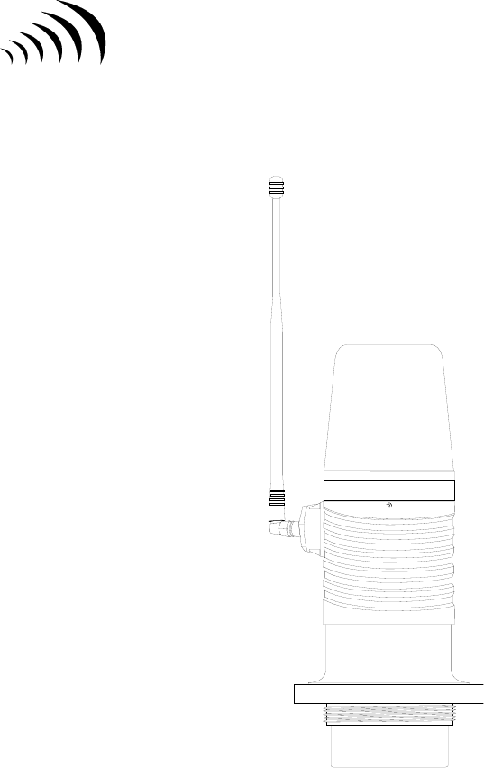
Note: The Sentinel
™
is shipped with the antenna disconnected. It is located in a
separate compartment within the shipping carton. Verify that the antenna is
present before proceeding.

S
U P P L Y
N
E T
C O M M U N I C A T I O N S L . L . C .
Getting Started – Chapter 1
Sentinel 2300 Series
/
Version 3.0 9/23/2004
Page 6
The Sentinel
™
communicates to the Base Station using a short range radio. The distance
is limited to 1000 feet. The Base Station is capable of receiving data from multiple
Sentinels forming a Local Area Network (LAN) configuration. The maximum number of
Sentinels communicating with the Base Station is 24. The Base Station in turn
communicates directly with the TankLink
®
data center using a wireless cellular
technology called Microburst
®
. This patented technology allows the unit to transmit
digital data to the TankLink
®
data center using the existing network of analog cellular
towers deployed throughout North America. Every area with analog cellular service has
two carriers, an ‘A’ carrier and a ‘B’ carrier. In order to transmit a Microburst
®
data
packet, the local cellular carrier must be Microburst
®
enabled. Fortunately, nearly all
areas in the United States have at least one Microburst
®
enabled carrier. Many regions
have two Microburst
®
carriers. In these areas, the installing technician can choose which
carrier to use based on the proximity of the unit to each carrier’s cellular towers. There is
no difference in cost using one carrier over the other, unlike cellular telephone rate plans
from competing companies. Once the data is at the TankLink
®
data center, it may be
viewed over the internet using a standard web browser (ie. Microsoft Internet Explorer or
Netscape Navigator), downloaded to applications such as Microsoft Excel, or it may be
used to trigger events such as an e-mail or page to a local sales or service representative.
To access the data provided by the Sentinel
™
unit, a current monitoring service
agreement with SupplyNet Communications is required. For help with accessing the
TankLink
®
web site, see Chapter 5. Since the Sentinel
™
is a wireless device, care must
be taken when installing the unit to minimize interference from nearby equipment or
structures. For installation guidelines, please refer to Chapter 2.
1-3 Product Highlights
# No telephone line is required for communication.
# No external power source is required.
# Simple installation.
# Sensor flexibility.
# Quick commissioning.
# Fixed monitoring costs.
# Unlimited applications.
S
U P P L Y
N
E T
C O M M U N I C A T I O N S L . L . C .
Getting Started – Chapter 1
Sentinel 2300 Series
/
Version 3.0 9/23/2004
Page 5
1-1 Overview
The SupplyNet Communications Sentinel
™
2300 Series is a wireless communication
device that provides quick and easy access to remote information such as storage tank
inventory. Intended for supplier-managed inventory programs, the Sentinel
™
utilizes the
latest in internet and cellular technology to provide instant access to inventory
information around the globe. Coupled with the TankLink
®
information web site, the
Sentinel
™
can provide a tremendous advantage over conventional systems for inventory
management, asset control, or information exchange.
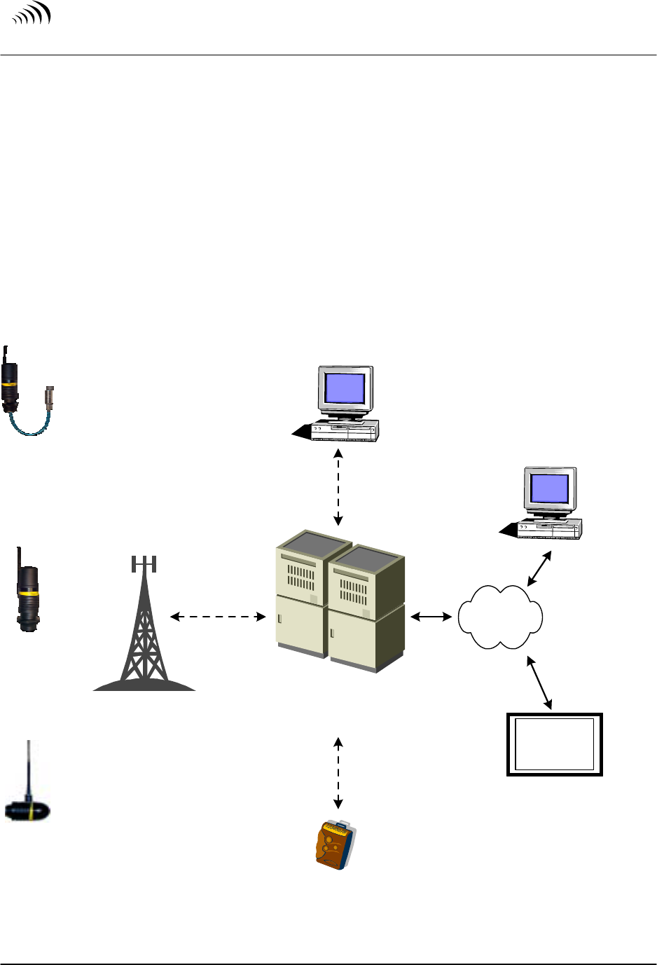
1-2 Theory of Operation
Differential
Pressure
Sensor
Ultrasonic
Level
Sensor
Universal
Uplink
Module
E - Mail Alert
Any Analog
Phone Line
TankLink
Data Center
TankLink.com
Website
Cell
Tower
Secure
Private
Link
Internet
Pager
Secure
Internet
SmartView
TM
Picture Frame
OR
Figure 1
Transfer of Data

S
U P P L Y
N
E T
C O M M U N I C A T I O N S L . L . C .
Sentinel 2300 Series
/
Version 3.0 9/23/2004
Page 4
Table of Contents
Chapter 1 Getting Started
1-1 Overview 4
1-2 Theory of Operation 4
1-3 Product Highlights 5
Chapter 2 Installation
2-1 Safety Precautions 6
2-2 Initial Inspection 6
2-3 Stainless Steel Tank Preparation 7
2-4 Poly Tank Preparation 8
2-5 Mounting the Unit (Ultrasonic) 9
2-6 Mounting the Unit (Pressure Differential) 11
2-7 Tank Measurements 13
Chapter 3 Communication Setup
3-1 Setting the Network Address 14
3-2 Determining the Signal Strength 15
3-3 Remote Tank Unit ID 15
3-4 Setting the number of callouts per day 16
Chapter 4 Unit Operation
4-1 Final Testing 18
4-2 Normal Operation 18
Chapter 5 Viewing your Data on the Internet
5-1 Accessing the TankLink.com Web site 19
Chapter 6 Specifications
6-1 Sentinel Specifications 20
Chapter 7 Troubleshooting and Technical Support
7-1 Error Codes 21
7-2 Jumper Settings 22
7-3 Battery Pack Replacement 23
7-4 Troubleshooting 24
7-5 Obtaining Technical Support 24
Chapter 8 Terms and Conditions of Service
8-1 Terms and Conditions of Service 25
Chapter 9 Product Warranty and Notices
9-1 Product Warranty and Notices 26

S
U P P L Y
N
E T
C O M M U N I C A T I O N S L . L . C .
Sentinel 2300 Series
/
Version 3.0 9/23/2004
Page 3
No part of this document may be copied, reproduced, or translated without the prior written consent of
SupplyNet Communications. No part of this document may be stored or transmitted in any electronic form
without the prior written consent of SupplyNet Communications.
SupplyNet Communications has made every effort to ensure the accuracy and completeness of this document.
However, as we are continually making improvements to our products, we cannot guarantee the accuracy of this
document. We will not be liable for any inaccuracies, omissions, or future changes.
TankLink and the TankLink logo are registered trademarks of SupplyNet Communications L.L.C.
Microburst is a registered trademark of Aeris.Net. Lexan and Valox are registered trademarks of General
Electric Company. All other trademarks referenced herein are the properties of their respective organizations.

S
U P P L Y
N
E T
C O M M U N I C A T I O N S L . L . C .
Sentinel 2300 Series
/
Version 3.0 9/23/2004
Page 2
FCC Statement
This device complies with Part 15 of the FCC Rules. Operation is subject to the following
two conditions: (1) This device must not be allowed to cause harmful interference, (2) This
device must accept any interference that may cause undesired operation.
For Your Safety
This equipment contains a short range radio which transmits at very low power. In non-
residential applications, it may still interfere with other electronic equipment. Therefore its
use in certain situations is restricted.
Read these installation and operation instructions carefully. Failure to follow these
instructions may be dangerous or illegal and any unauthorized changes may void the users
authority to operate the equipment.
Only qualified service personnel must install or repair this equipment. This device has been
tested with a specific antenna and tampering or replacing it is strictly prohibited.
RF Exposure Warnings for Portable Equipment.
This equipment has been approved for portable applications where the equipment can be
used in close proximity to the human body. Excessive RF exposure should be avoided.
This equipment has been approved for portable applications where the equipment should be
used at distances greater than 20cm from the human body (with the exception of hands,
wrists, feet, ankles). Operation at distances less than 20 cm is strictly prohibited.
Copyright 2001 SupplyNet Communications L.L.C.
SU P P L Y NE T
C O M M U N I C A T I O N S L . L . C .
T a n k L i n k
S e n t i n e l
TankLink
®
Sentinel
™
Wireless Remote Tank Unit
2300 Series
LOCAL AREA NETWORK VERSION
9/15/2004
Document Version 3.0