User manual

2
ⒸCopyright 2007Suprema Inc.
Contents
Safety precautions 3
Basics of fingerprint recognition 5
How to place a finger 6
Product Contents 8
Front Side 10
Bottom and Back Side 11
Product Dimension 12
Cables and Connectors 13
Installation of Wall-mount Bracket 14
Power Connection 15
Ethernet Connection 16
RS485 Connection 18
Relay Connection 20
Digital Input Connection 23
Wiegand Output 25
Installation Reference 26
Electrical Specification 29
General Specification 30
Troubleshooting 31
Device cleaning 32
FCC Rules 33
Caution 34
3
ⒸCopyright 2007Suprema Inc.
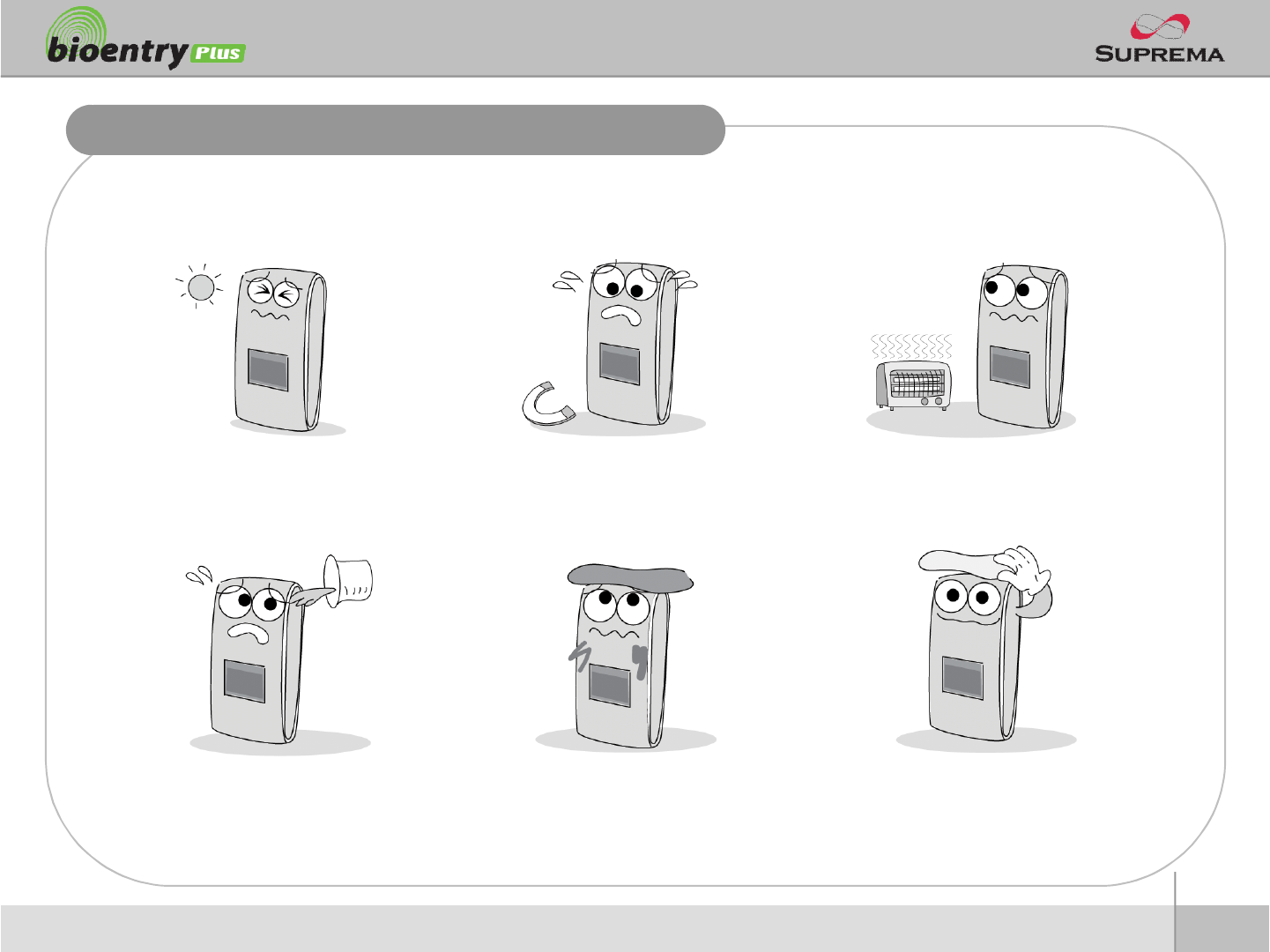
Safety precautions
nThe list below is to keep user’s safety and prevent any loss. Please read carefully before
use.
Do not install the device in a
place subject to direct sun light,
humidity, dust or soot.
Do not place a magnet near the pr
oduct. Magnetic objects such as
magnet, CRT, TV, monitor or spe
aker may damage the device.
Do not place the device next to
heating equipments.
Be careful not to let liquid like
water, drinks or chemicals leak
inside the device.
Clean the device often to remove
dust on it.
In cleaning, do not splash water
on the device but wipe it out with
smooth cloth or towel.
4
ⒸCopyright 2007Suprema Inc.
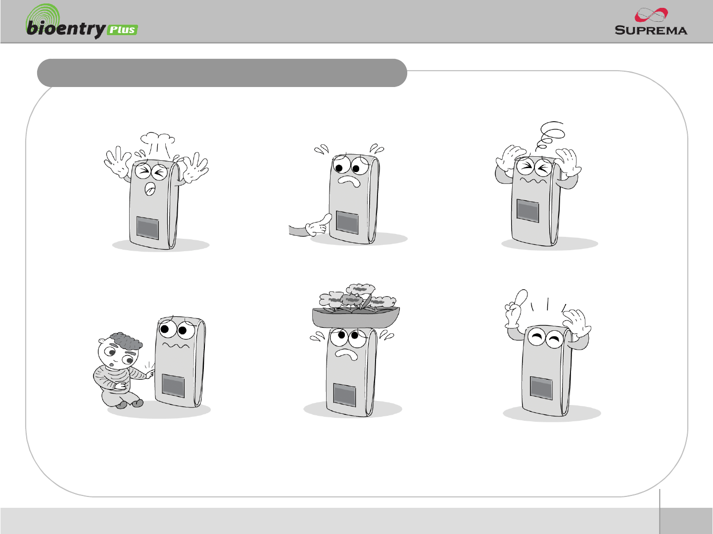
Safety precautions
nThe list below is to keep user’s safety and prevent any loss. Please read carefully before
use.
Do not drop the device. Do notdamage the device. Do not disassemble, repair or
alter the device.
Do not let children touch the
devicewithout supervision.
Do not use the device for any
other purpose than specified.
Contact your nearest dealer in
case of a trouble or problem.

5
ⒸCopyright 2007Suprema Inc.
Basics of fingerprint recognition
nWhat is fingerprint recognition?
lFingerprint is an individual’s own biometric information and does not change throughout his/her life.
Fingerprint recognition is a technology that verifies or identifies an individual using such fingerprint
information.
lFree from the risk of theft or loss, fingerprint recognition technology is being widely used in security
systems replacing PIN or cards.
nProcess of fingerprint recognition
lFingerprint consists of ridges and valleys. Ridge is a flow of protruding skin in a fingerprint while
valley is a hollow between two ridges. Each individual has different pattern of ridges and valleys
and finger recognition makes use of such originality and uniqueness of these patterns.
lFingerprint sensor generates 2-dimentional fingerprint image using different technology. According
to the sensing technology, fingerprint sensors are classified into optical, capacitive, or thermal.
lFingerprint template is a collection of numeric data representing the features of a fingerprint.
Fingerprint templates are saved inside the memory of BioStation and used for identification.
nSecure way to protect personal information
lTo avoid privacy concern, Suprema’s fingerprint products do not save fingerprint images itself. It is
impossible to reconstruct a fingerprint image from a fingerprint template which is just numeric data
of the features of a fingerprint.
6
ⒸCopyright 2007Suprema Inc.
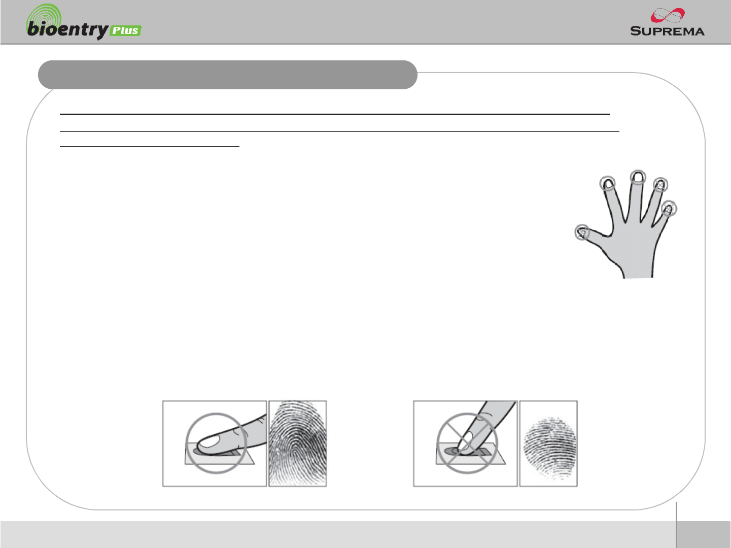
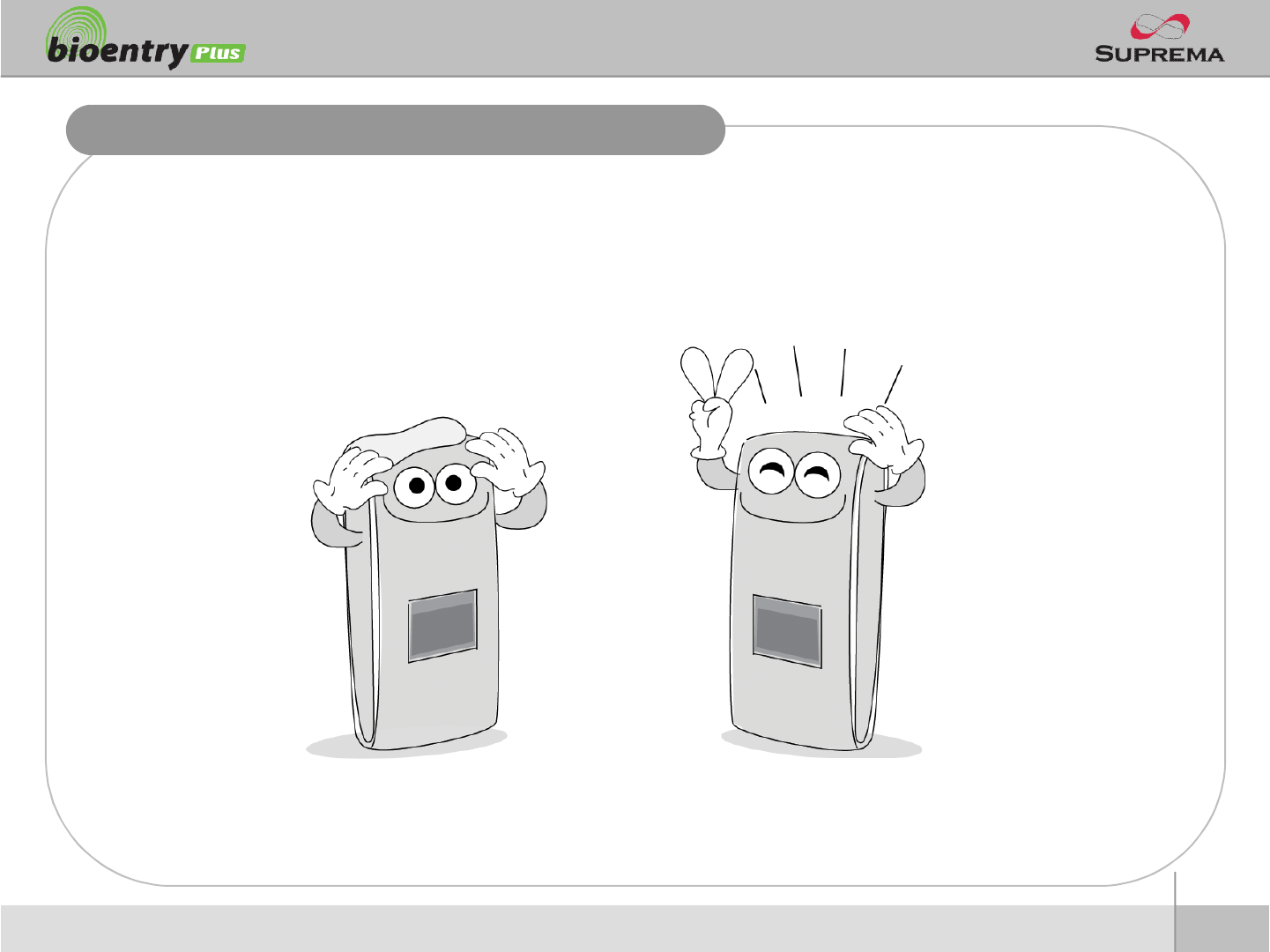
How to place a finger
Suprema’s fingerprint products show an outstanding recognition performance regardless of the user’s fingerprint
skin condition or the way of fingerprint positioning. However, following tips are recommended to get more optimal
fingerprint recognition performance.
nSelect a finger to enroll
lIt is recommended to use an index finger or a middle finger.
lThumb, ring or little finger is relatively more difficult to place in a correct position.
nHow to place a finger on a sensor
lPlace a finger such that it completely covers the sensor area with maximum contact.
lPlace core part of a fingerprint to the center of a sensor.
§People tend to place upper part of a finger.
§The core of a fingerprint is a center where the spiral of ridges is dense.
§Usually core of fingerprint is the opposite side of the lower part of a nail.
§Place a finger such that the bottom end of a nail is located at the center of a sensor.
lIf a finger is placed as in the right picture, only a small area of a finger is captured. So it is
recommended to place a finger as shown in the left picture.
7
ⒸCopyright 2007Suprema Inc.
How to place a finger
nTips for different fingerprint conditions
lSuprema’s fingerprint products are designed to scan fingerprint smoothly regardless of the
conditions of a finger skin. However, in case a fingerprint is not read well on the sensor, please
refer to the followings tips.
§If a finger is stained with sweat or water, scan after wiping moisture off.
§If a finger is covered with dust or impurities, scan after wiping them off.
§If a finger is way too dry, place after blowing warm breath on the finger tip.
nTips for fingerprint enrollment
lIn fingerprint recognition, enrollment process is very important. When enrolling a fingerprint, please
try to place a finger correctly with care.
lIn case of low acceptance ratio, the following actions are recommended.
§Delete the enrolled fingerprint and re-enroll the finger.
§Enroll the same fingerprint additionally.
§Try another finger if a finger is not easy to enroll due to scar or worn-out.
lFor the case when an enrolled fingerprint cannot be used due to injury or holding a baggage, it is
recommended to enroll more than two fingers per user.
8
ⒸCopyright 2007Suprema Inc.
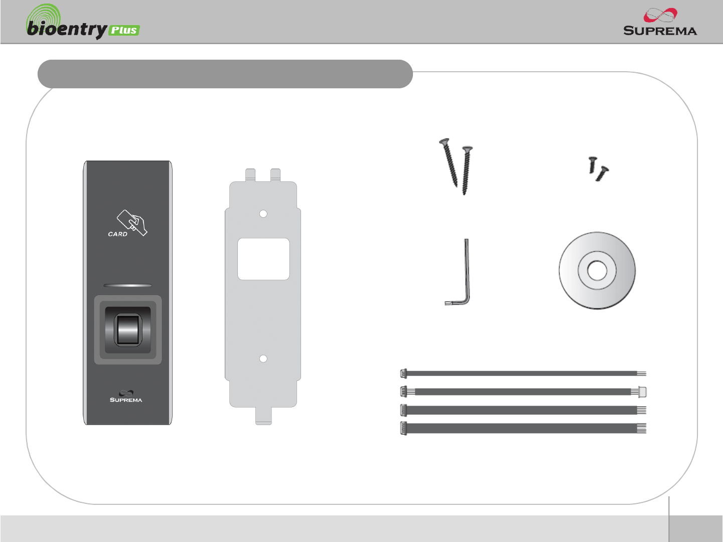
Product Contents
nBasic Contents
BioEntry Plus Wall-mounting metal bracket
Wall mounting screws –2 ea Star-shaped screws
Star-shaped small wrench
3 pin, 4 pin, 5 pin, 7pincables –each1 ea
Software CD
9
ⒸCopyright 2007Suprema Inc.
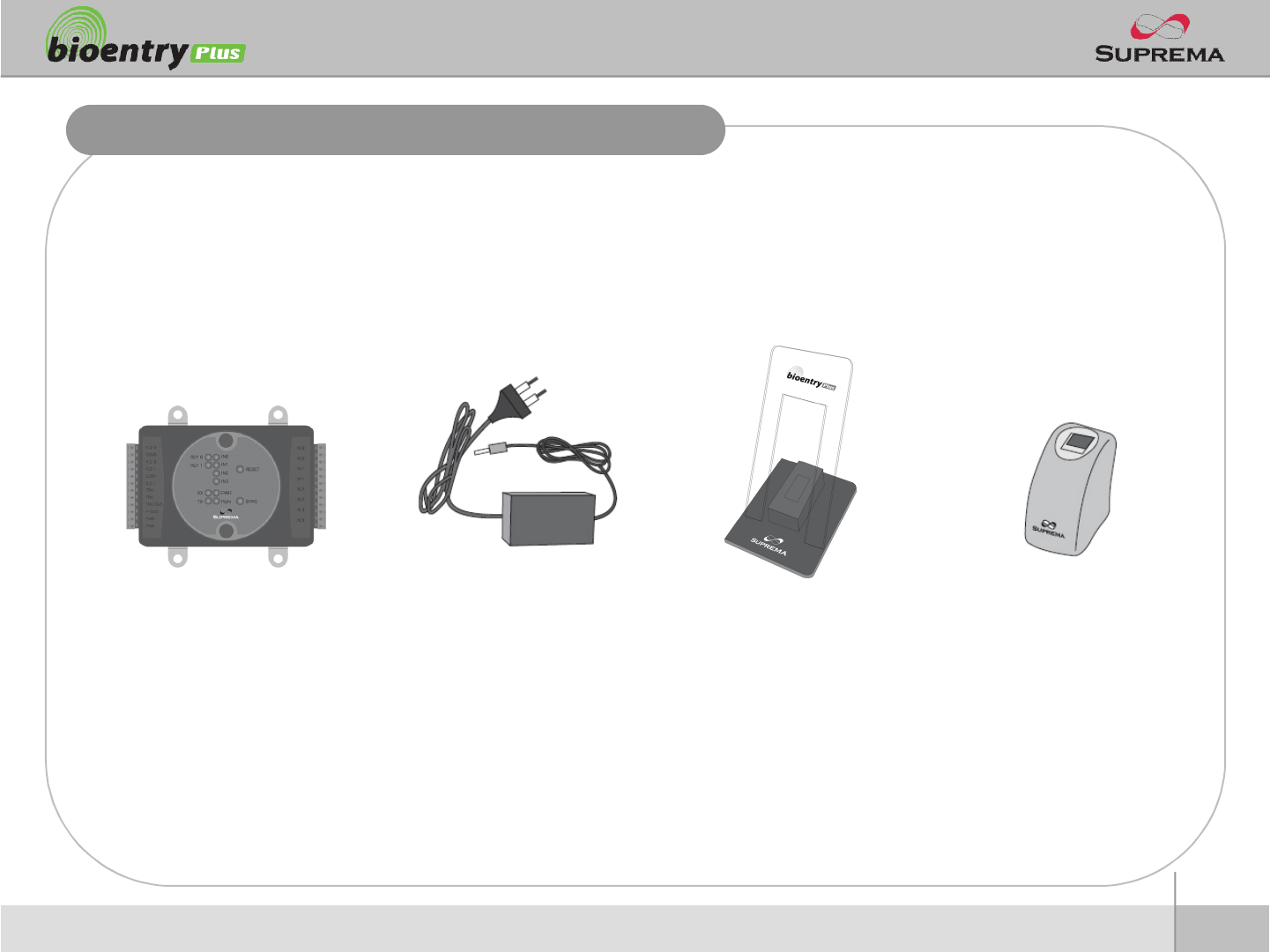
Product Contents
nOptional accessories
USB fingerprint scanner
for enrollment on PC
12V power adaptor Plastic stand
Secure I/O
10
ⒸCopyright 2007Suprema Inc.
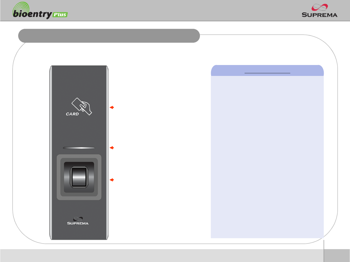
nFront
Front Side
RF card reading part
Place an RF card over the
picture
LED
Display current status using
seven different colors
Fingerprint sensing part
Place a finger on a sensor
surface
LED Status per Color
lGreen : Authorization Success
lRed : Authorization Fail
lPink : On Processing
lFlicker Blue/Sky-Blue Color per 2sec : Normal
lFlicker Red/Pink Color per 2sec : Locked
lFlicker Blue/Red Color per 2sec : Initialized
Time due to the Internal Battery Discharge
lFlicker Blue/Yellow Color per 2sec : DHCP
Fail
lFlicker Red Color per 2sec : Failed. Please
contact to your distributor or Suprema
lFlicker Yellow Color per 2sec : Waiting Input
lFlicker Yellow Color per 1sec : Receiving IP
Address from DHCP server
11
ⒸCopyright 2007Suprema Inc.
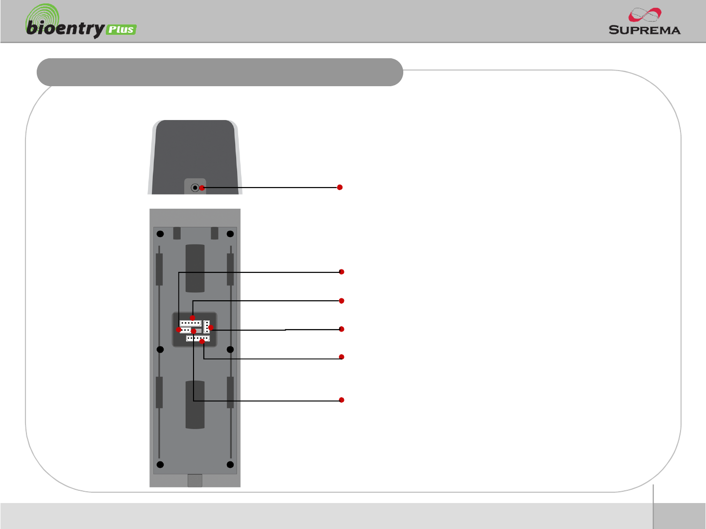
Bottom and Back Side
nBottom
nBack
Star-shaped screw hole for fixing a body to a metal bracket
3 pin connector –wiegand output
5 pin connector –power and RS485
4 pin connector –ethernet (TCP/IP)
7 pin connector –digital input and relay output
DIP switch –RS485 termination setting
(Refer to “RS485 Connection” pages for details)
12
ⒸCopyright 2007Suprema Inc.
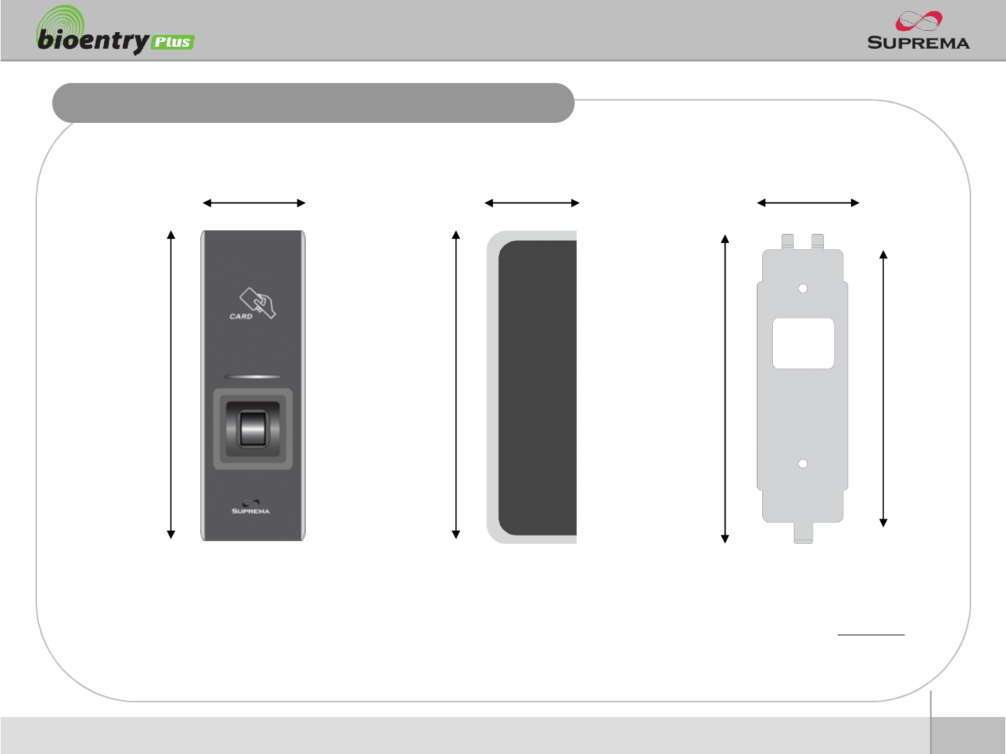
Product Dimension
Metal BracketFront Side
160
50 37
150
40
135
(unit : mm)
160
13
ⒸCopyright 2007Suprema Inc.
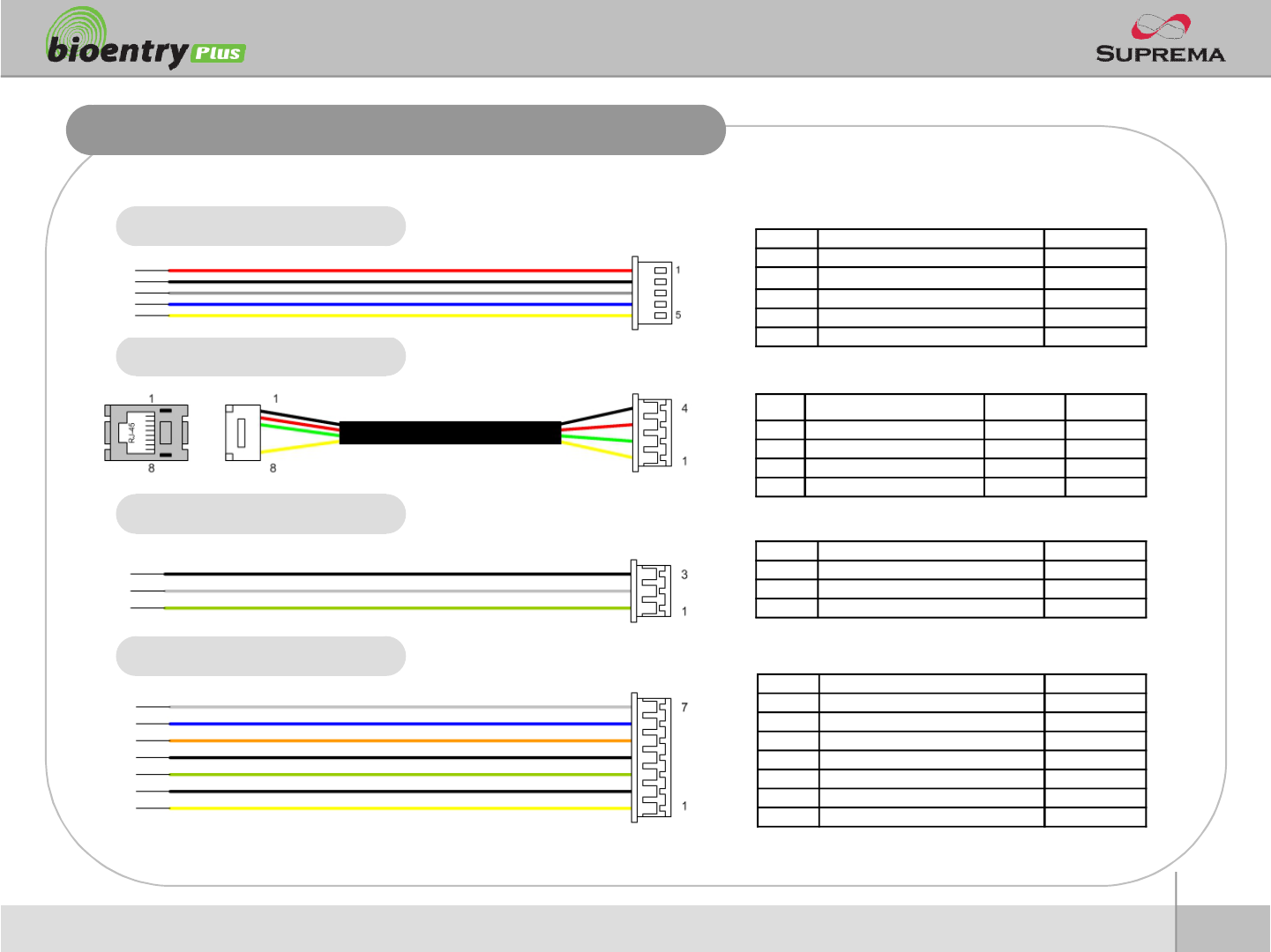
Cables and Connectors
Power and RS485
TCP/IP
Wiegand output
Digital Inputs and Relay output
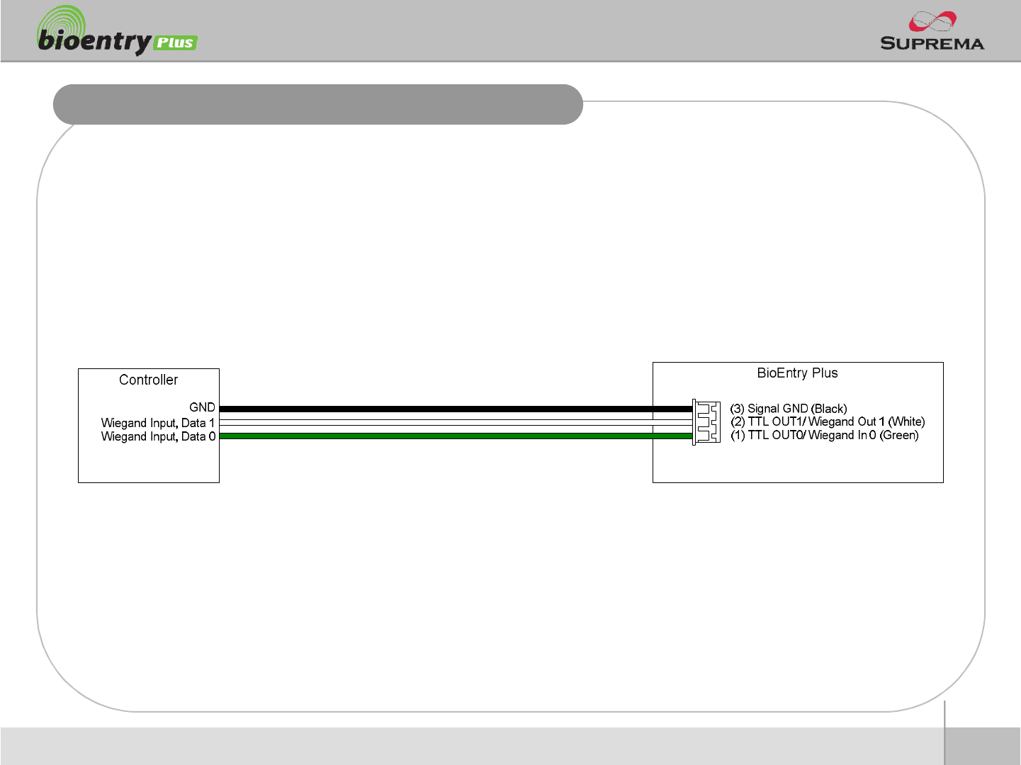
PIN PIN DESCRIPTION WIRE
1WIEGAND DATA0 GREEN
2WIEGAND DATA1 WHITE
3WIEGAND GND BLACK
PIN PIN DESCRIPTION WIRE
1POWER +12V RED
2 POWER GND BLACK
3 RS -485 GND GRAY
4RS -485 TRX+ BLUE
5 RS -485 TRX- YELLOW
PIN PIN DESCRIPTION WIRE
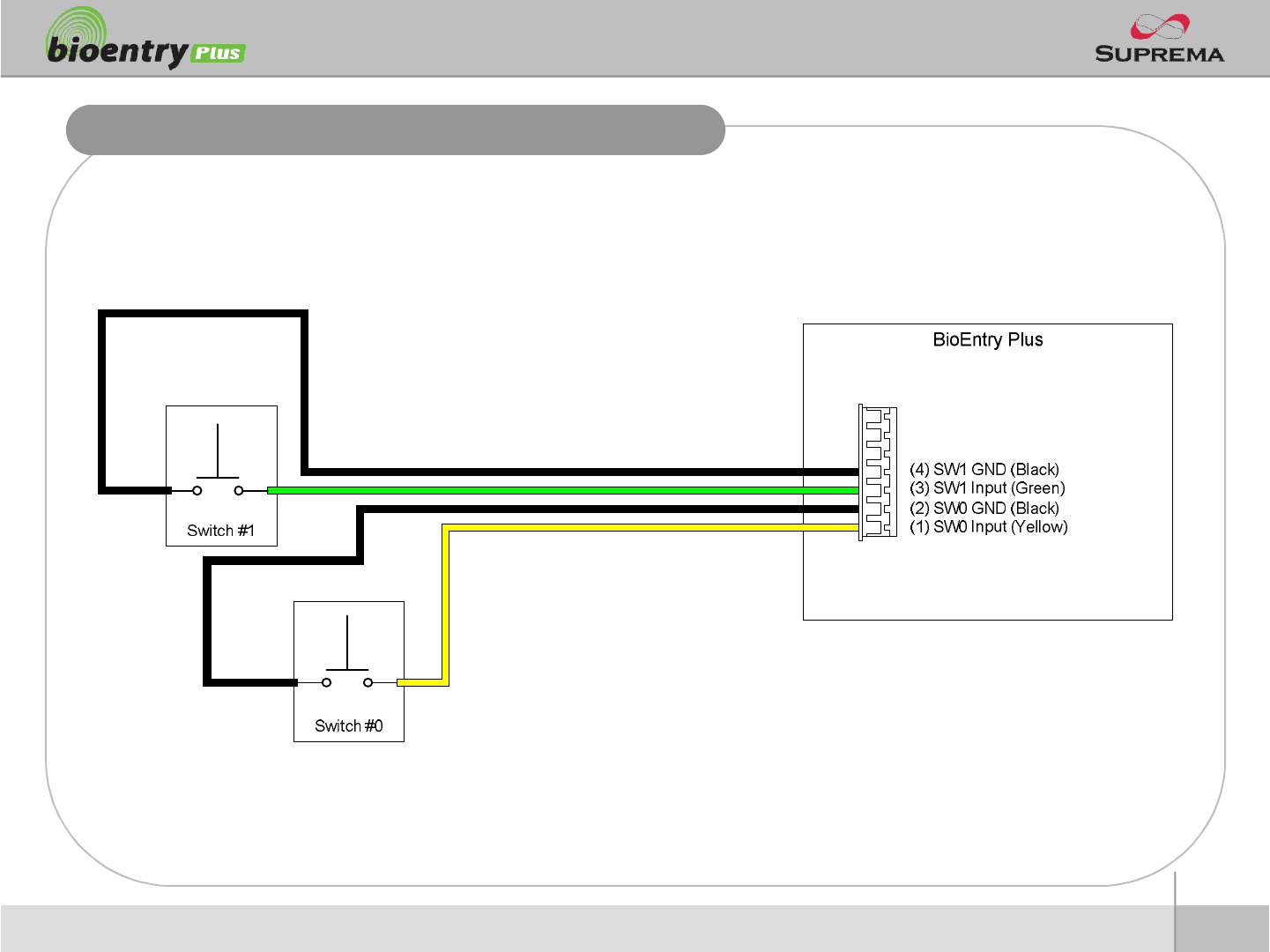
1SW1 INPUT YELLOW
2SW1 GND BLACK
3SW2 INPUT GREEN
4 SW2 GND BLACK
5 RELAY NORMAL CLOSE ORANGE
6RELAY COMMON BLUE
7 RELAY NORMAL OPEN WHITE
PIN PIN DESCRIPTION WIRE RJ45 PIN
1TX + YELLOW 6
2TX - GREEN 3
3RX + RED 2
4RX - BLACK 1
14
ⒸCopyright 2007Suprema Inc.
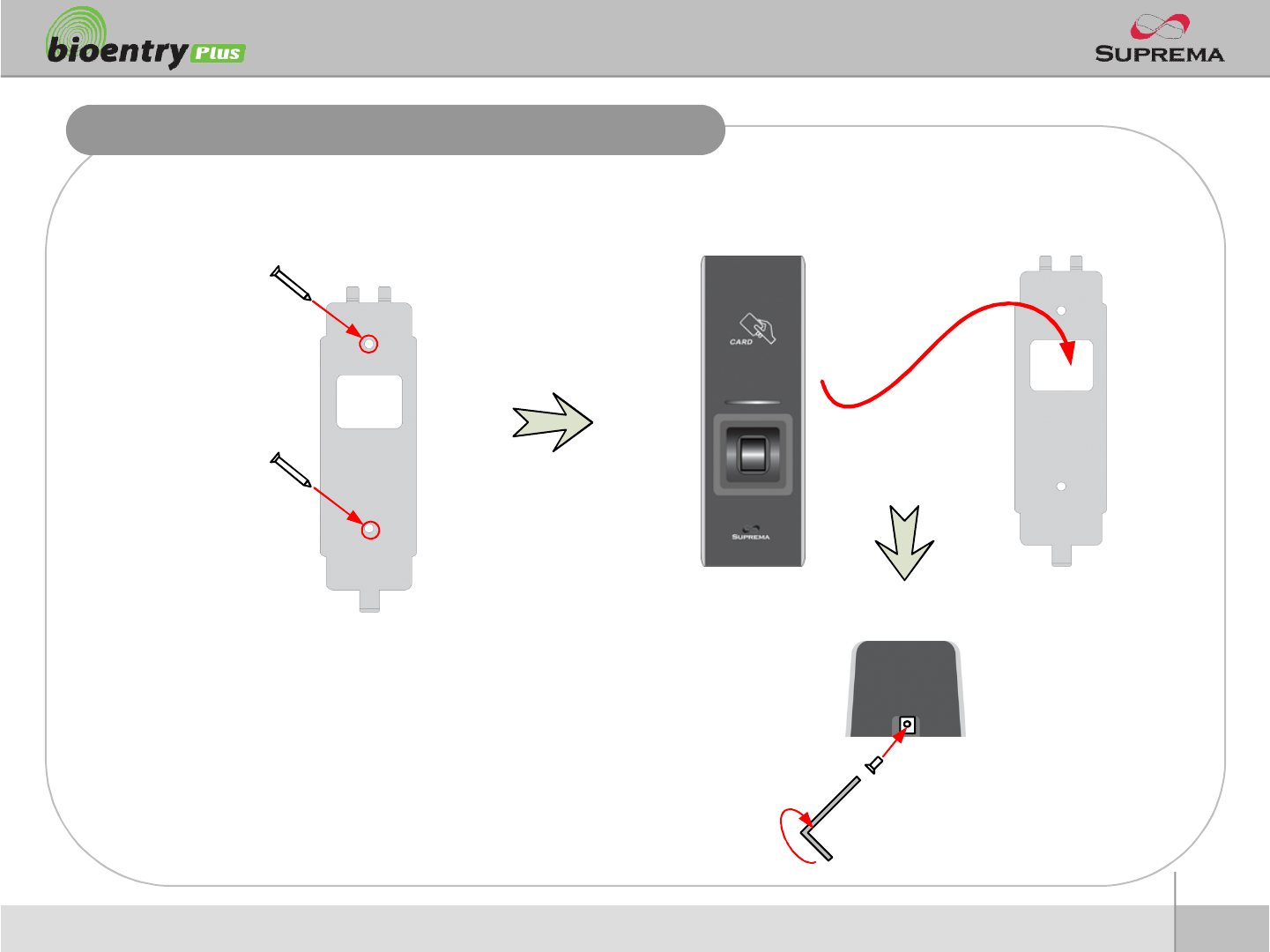
Installation of Wall-mount Bracket
nFix wall mount bracket on a wall using wall mounting
screws
nHook BioEntry Plus on the wall mount bracket
nFix BioStation and wall mounting bracket using a star
shape screw.
Wall mounting
screws
Star-shaped
screw
Star-shaped
wrench
15
ⒸCopyright 2007Suprema Inc.
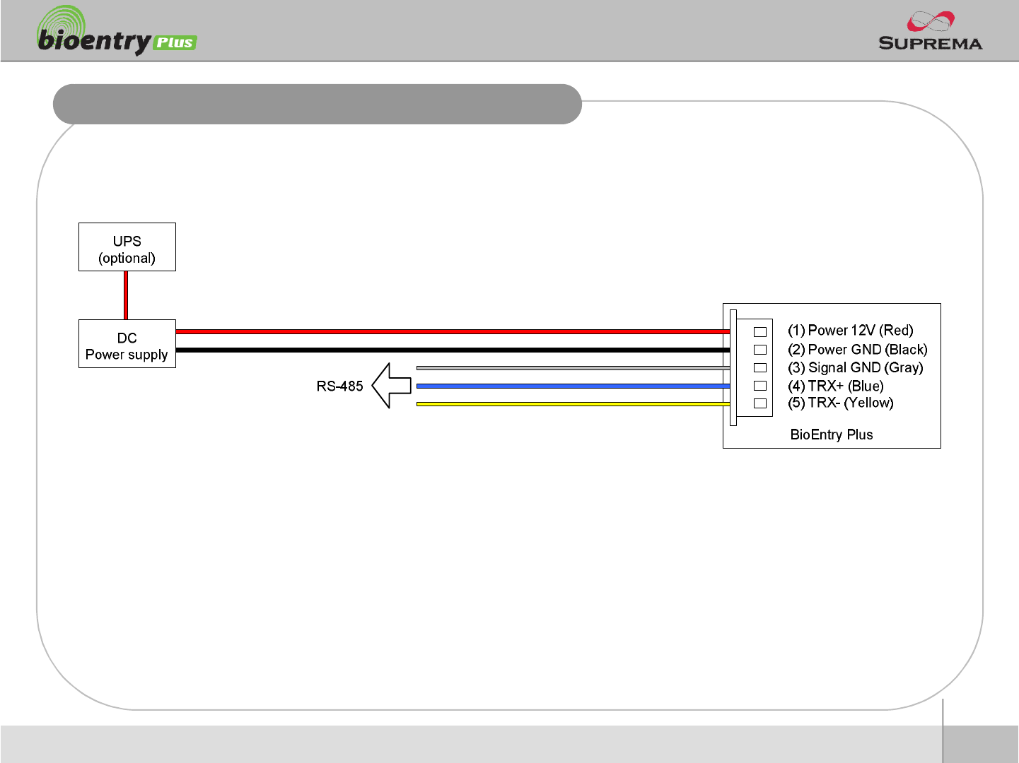
Power Connection
nRecommended power supply
l12V ±10%, at least 1500mA.
lComply with standard IEC/EN 60950-1.
lTo share the power with other devices, use a power supply with higher current ratings.
16
ⒸCopyright 2007Suprema Inc.
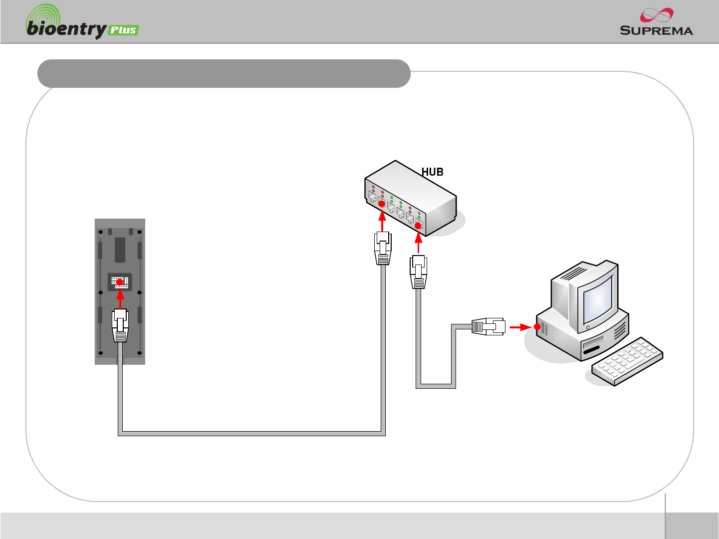
Ethernet Connection
17
ⒸCopyright 2007Suprema Inc.
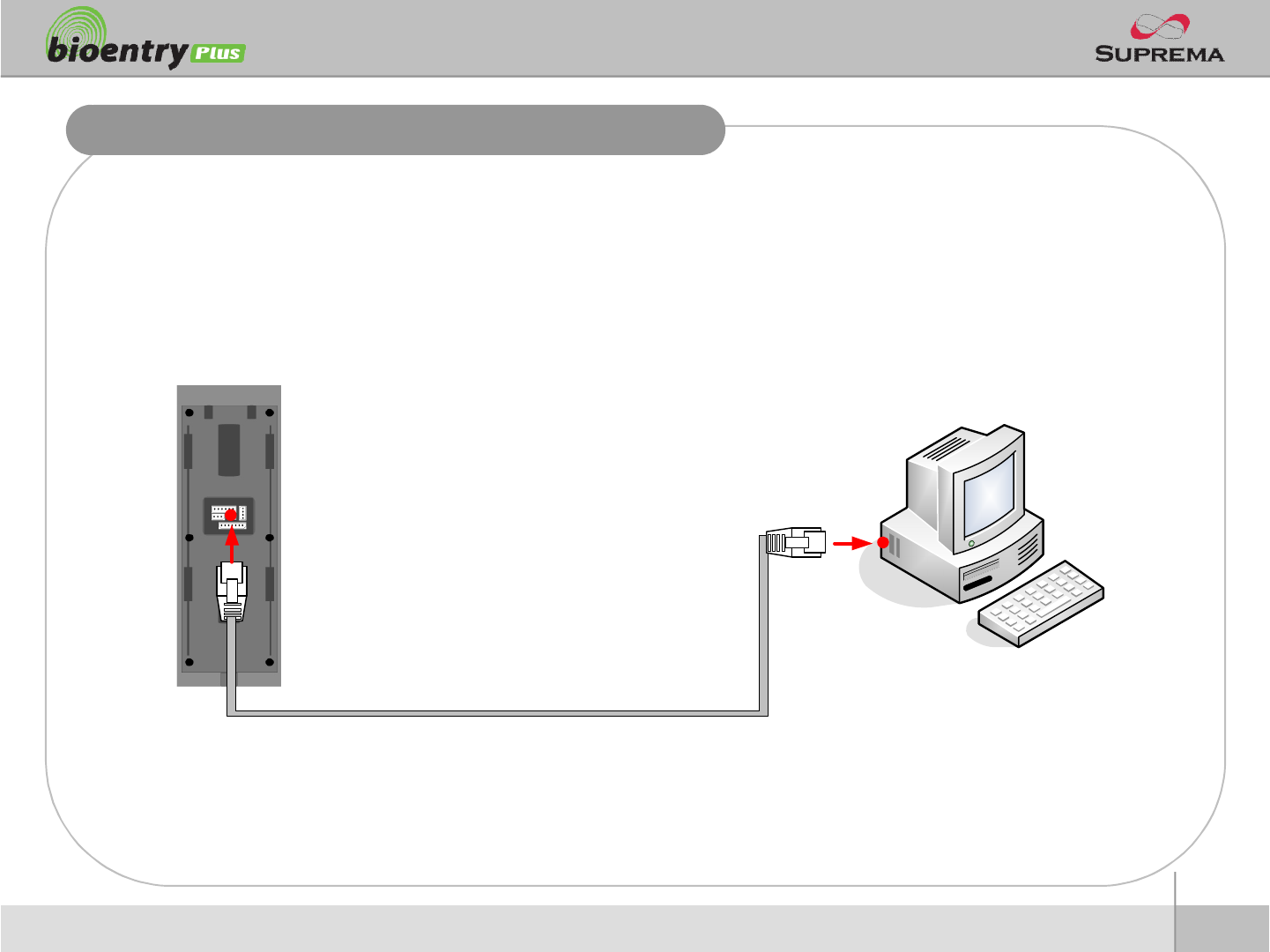
Ethernet Connection (Direct connection with PC)
nTo connect BioEntry Plus with a PC directly, connect both devices with a straight CAT-5
cable. As the BioEntry Plus supports auto MDI/MDIX feature, it is not necessary to use a
crossover type cable.
18
ⒸCopyright 2007Suprema Inc.
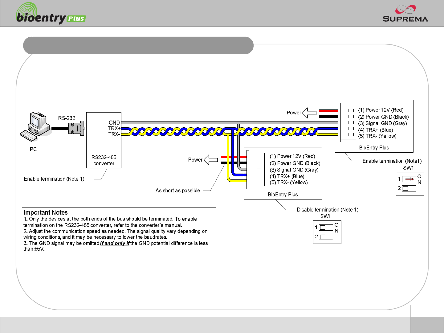
RS485 Connection for Host Communication
19
ⒸCopyright 2007Suprema Inc.
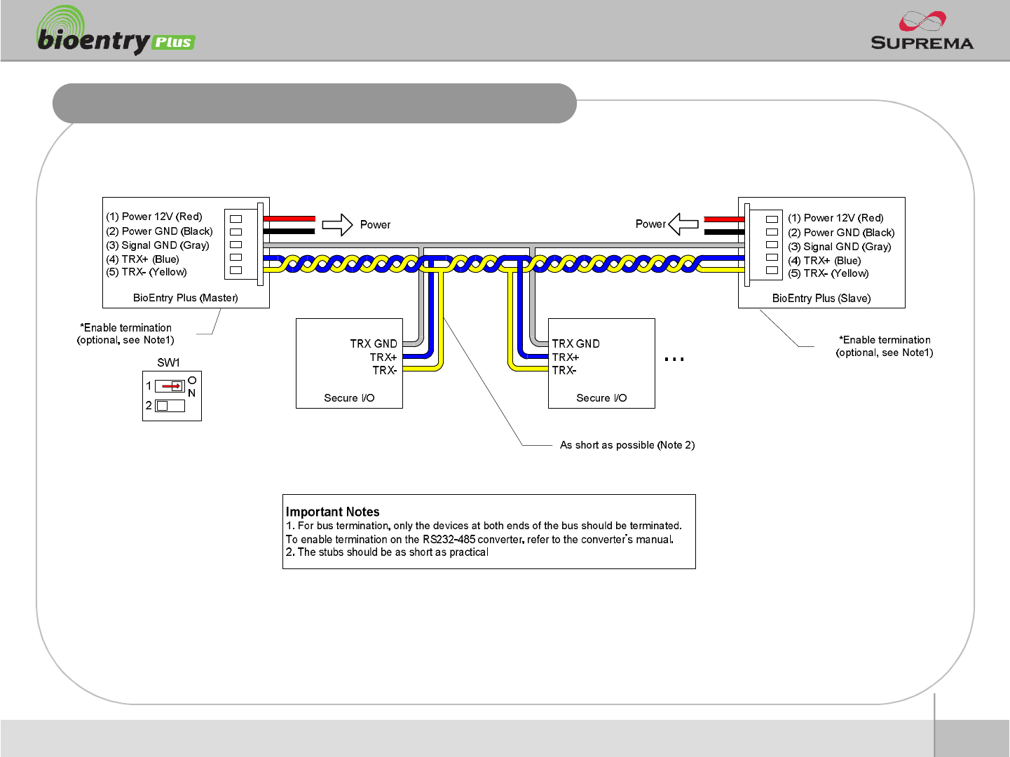
RS485 Connection for Secure I/O
nMax number of devices
lMaximum numbers of devices in an RS485 loop are two(2) devices (BioStation or BioEntry
Plus) and four(4) Secure I/Os
20
ⒸCopyright 2007Suprema Inc.
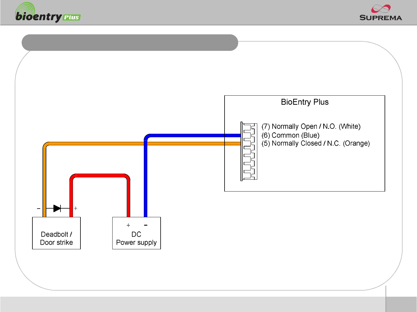
Relay Connection –Fail safe lock
21
ⒸCopyright 2007Suprema Inc.
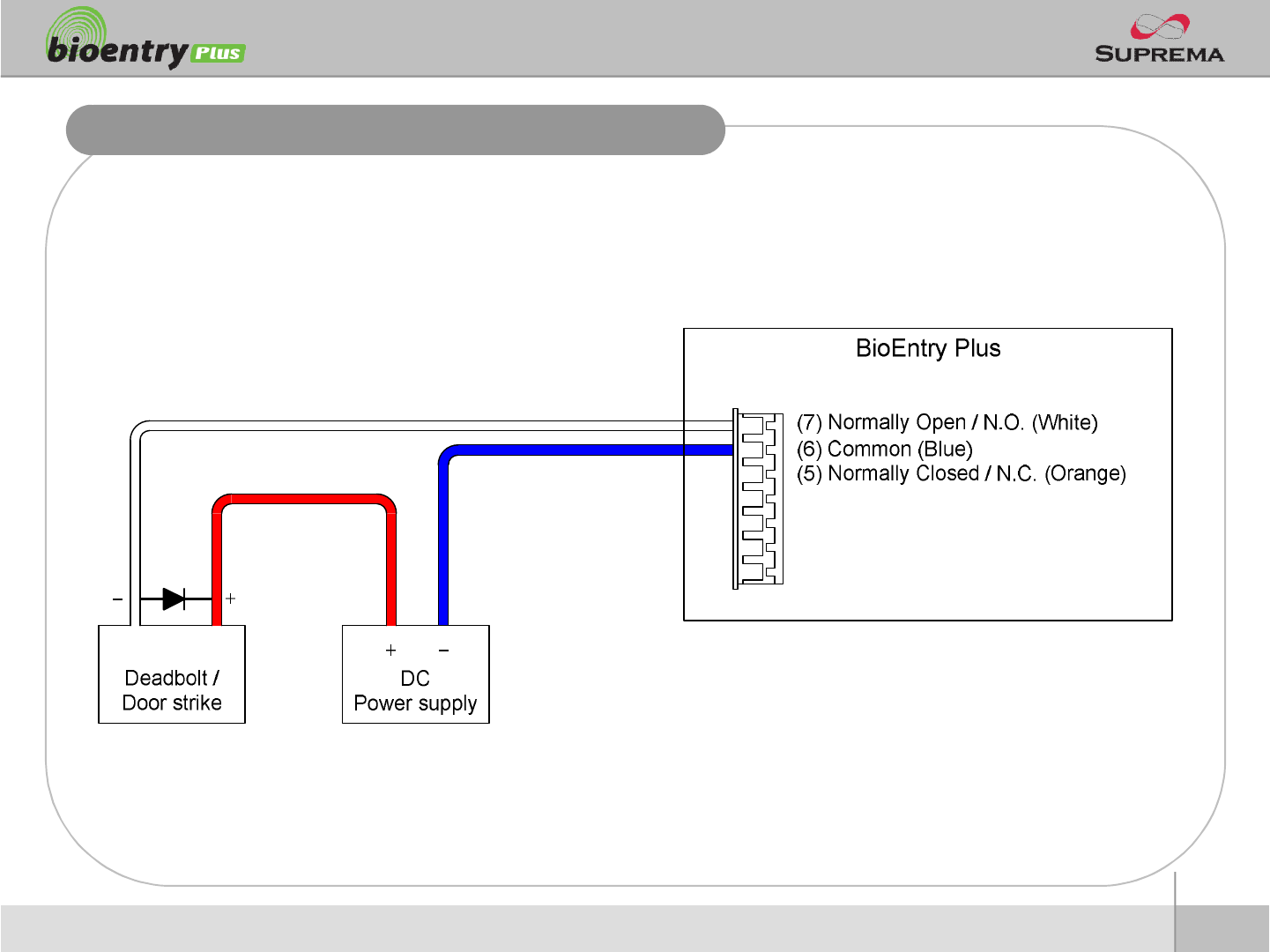
Relay Connection –Fail secure lock
22
ⒸCopyright 2007Suprema Inc.
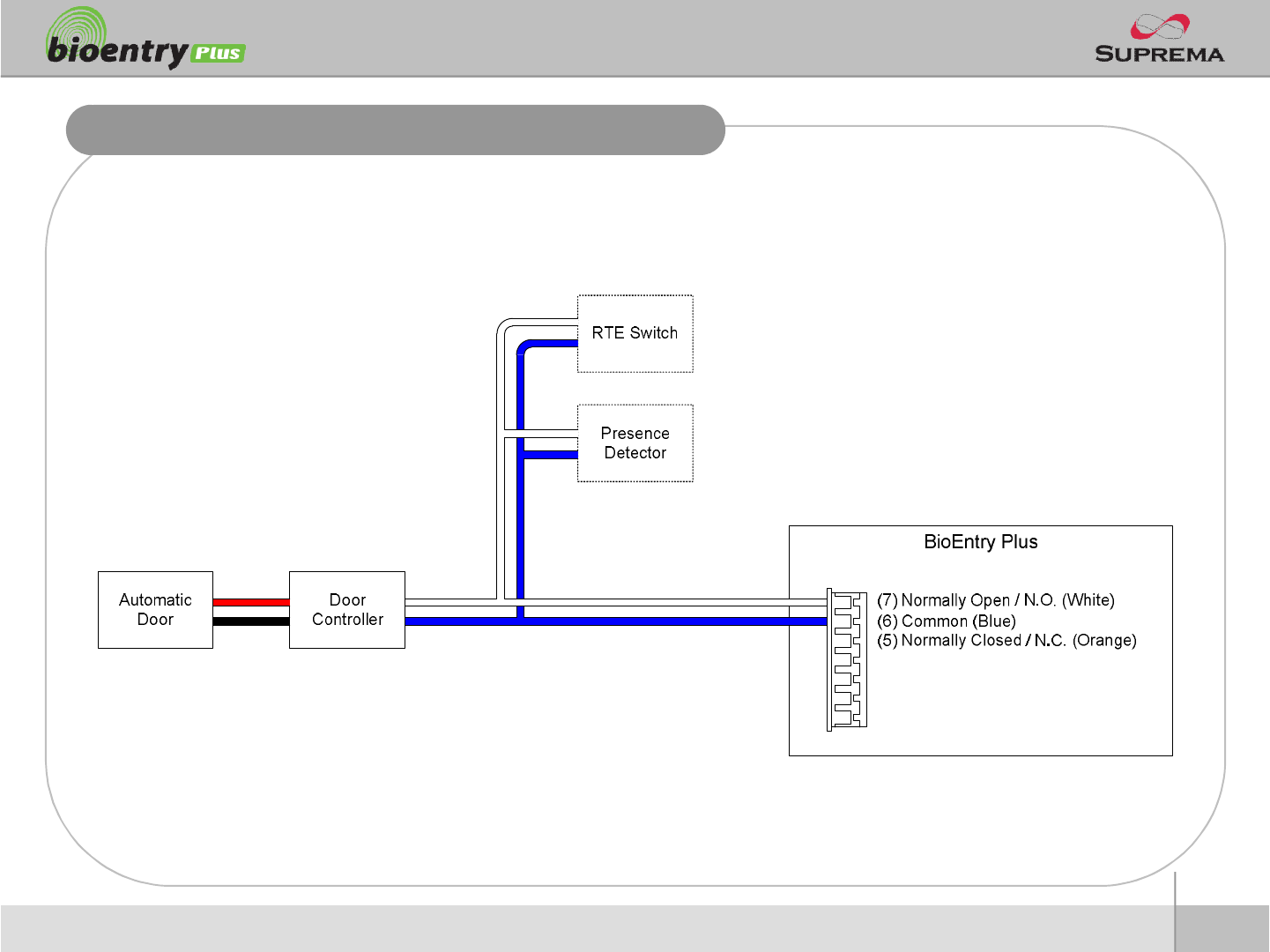
Relay Connection -Automatic door

23
ⒸCopyright 2007Suprema Inc.
Digital Input Connection (RTE, Door sensor)
24
ⒸCopyright 2007Suprema Inc.
Digital Input Connection (Alarm, Emergency sw)
25
ⒸCopyright 2007Suprema Inc.
Wiegand Output
26
ⒸCopyright 2007Suprema Inc.
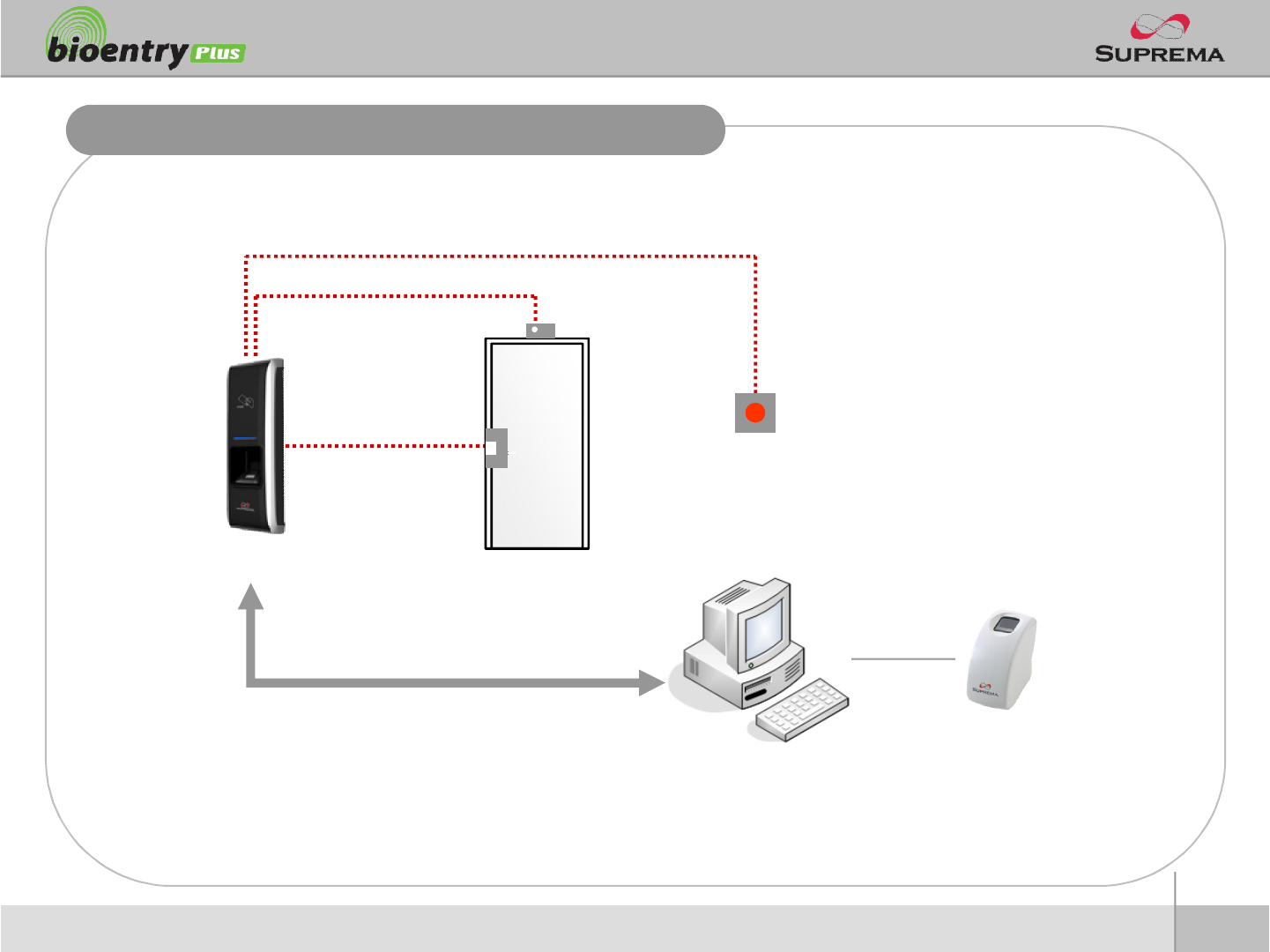
Installation Reference 1 -Stand alone
Door Lock
Door Sensor
Exit Button
Enroll ScannerPC
LAN
BioEntry Plus
27
ⒸCopyright 2007Suprema Inc.
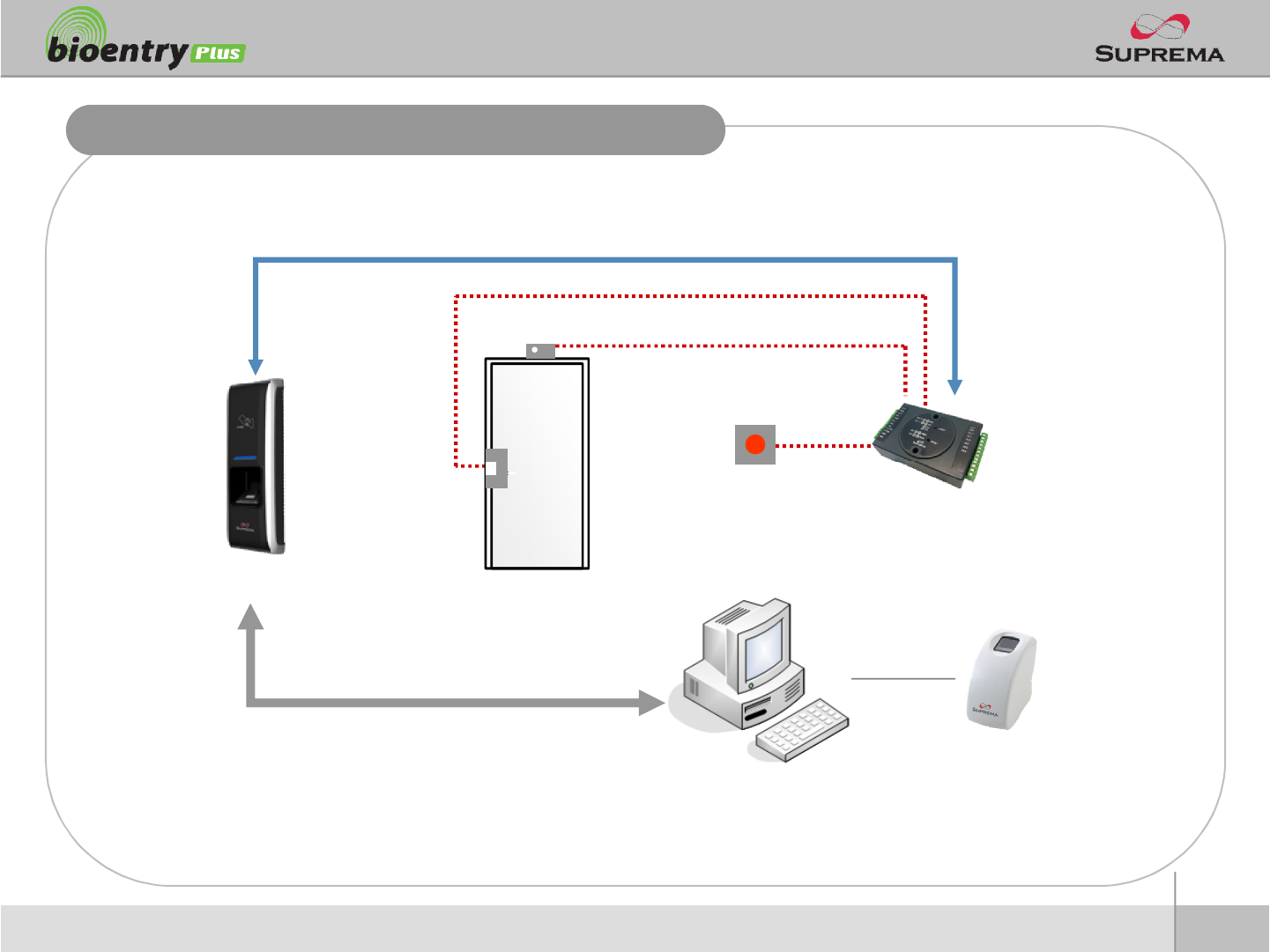
Installation Reference 2 –Secure
Exit Button
Enroll ScannerPC
LAN
BioEntry Plus
RS485
Secure I/O
Door Sensor
Door Lock
28
ⒸCopyright 2007Suprema Inc.
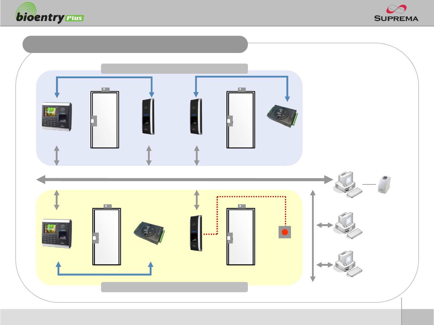
Installation Reference 3 –Network
Door Zone 2 (Anti passback)
Door Zone 1 (Anti passback)
BioStation BioEntry Plus BioEntry Plus Secure I/O
RS485 RS485
LAN
BioStation Secure I/O BioEntry Plus Exit Button
PC Server
PC Client
PC Client
RS485
Enroll Scanner
29
ⒸCopyright 2007Suprema Inc.
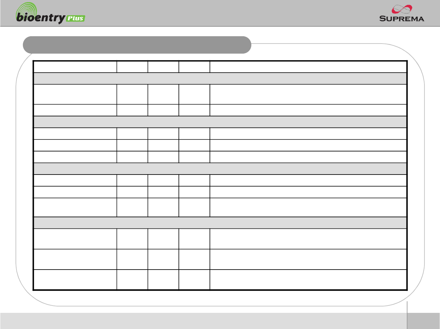
Electrical Specification
Min. Typ. Max. Notes
Power
Voltage (V) 10.8 12 13.2 Use regulated DC power adaptor only
Current (mA) -250
Switch Input
VIH (V) -TBD -
VIL (V) -TBD
Pull-up resistance (Ω)-4.7k - The input ports are pulled up with 4.7k resistors
TTL/Wiegand Output
VOH (V) - 5 -
VOL (V) -0.8 -
Pull-up resistance (Ω)-4.7k - The outputs ports are open drain type, pulled up with 4.7k resistors
internally
Relay
Switching capacity (A) - - 1
0.3
30V DC
125V AC
Switching power
(resistive) - - 30W
37.5VA
DC
AC
Switching voltage (V) - - 110
125
DC
AC
30
ⒸCopyright 2007Suprema Inc.
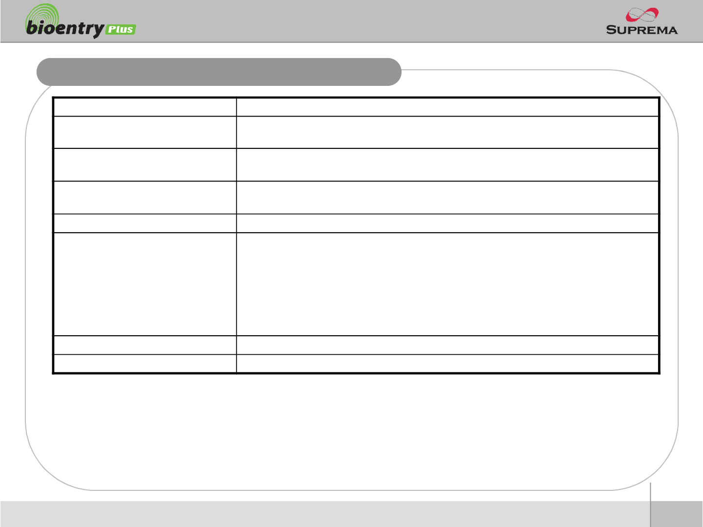
General Specification
Item Specification
CPU 400MHz DSP
Fingerprint Sensor OC Model : Optical Sensor
TC Model : Capacitive Sensor
IN/OUT Relay Out x 1, Switch Input x 2, Wiegand In/Out x 1
RS-485 x 1, Ethernet x 1
Power Input Rate DC12V, Max 250mA
Support Cards
BioEnteyPlus OC/TC Model (BEPL-OC/TC) :
-125KHz EM4100 Compatible Card Read
BioEntry Plus HID OC/TC Model (BEPH-OC/TC)
-125KHz HID Prox Compatible Card Read
BioEntry Plus MifareOC/TC Model (BEPM-OC/TC)
-13.56MHz MifareCard Read/Write
-13.56MHz ISO14443A Card CSN Read
Size 50 x 160 x 38 (Width x Height x Depth)
Certified KCC, CE, FCC

31
ⒸCopyright 2007Suprema Inc.
Troubleshooting
nFingerprint can not be read well or it takes too long.
lCheck whether a finger or fingerprint sensor is stained with sweat, water, or dust
lRetry after wiping off finger and fingerprint sensor with dry towel.
lIf a fingerprint is way too dry, blow on the finger and retry.
nFingerprint is entered but authorization keeps failing.
lCheck whether the user is restricted by door zone or time zone.
lInquire of administrator whether the enrolled fingerprint has been deleted frin the device for some
reason.
nAuthorized but door is not opened.
lCheck whether the time is set as lock time.
lCheck whether an antipass back mode is in use. In antipass back mode, only who entered can exit.
nDevice doesn’t operate though power is connected.
lCheck whether a device and a bracket is well connected to each other. If not, a tamper switch is
activated and the device doesn’t work.
32
ⒸCopyright 2007Suprema Inc.
Device cleaning
nWipe out machine surface with dry towel or cloth.
nIn case there is dust or impurities on the sensor of the BioStation, wipe off the surface with
dry towel.
nNote that if the sensor is cleaned by detergent, benzene or thinner, surface is damaged and
fingerprint can’t be entered.
33
ⒸCopyright 2007Suprema Inc.
FCC Rules
Caution
Warning
Information to User
lChanges or modifications not expressly approved by the manufacturer
responsible for compliance could void the user's authority to operate the
equipment.
lThis device complies with part 15 of the FCC Rules. Operation is subject to
the following two conditions: (1) This device may not cause harmful
interference, and (2) this device must accept any interference received,
including interference that may cause undesired operation.
lThis equipment has been tested and found to comply with the limit of a Class
B digital device, pursuant to Part 15 of the FCC Rules. These limits are
designed to provide reasonable protection against harmful interference in a
residential installation. This equipment generates, user and can radiate radio
frequency energy and, if not installed and used in accordance with the
instructions, may cause harmful interference to radio communications.
However, there is no guaranteee that interference will not occur in a particular
installation; if this equipment does cause harmful interference to radio or
television reception, which can be determined by turning the equipment off
and on, the user is encouraged to try to correct the interference by one or
more of the following measures:
1. Reorient / Relocate the receiving antenna.
2. Increase the separation between the equipment and receiver.
3. Connect the equipment into an outlet on a circuit difference from that
to which the receiver is connected.
4. Consult the dealer or an experienced radio/TV technician for help

34
ⒸCopyright 2007Suprema Inc.
Caution
nRISK OF EXPLOSION IF BATTERY IS REPLACED BY AN INCORRECT TYPE.
nDISPOSE OF USED BATTERIES ACCORDING TO THE INSTRUCTIONS.

Suprema Inc.
16F Parkview Office Tower, Jeongja-dong, Bundang-gu,
Seongnam, Gyeonggi, 463-863 Korea
E-mail : support@supremainc.com
Website : www.supremainc.com
Functions and specifications of the product are subject to changes without notice due to quality
enhancement or function update. For any inquiry on the product, please contact Suprema Inc.