User Manual

English
Version 1.00
BioEntry W2
INSTALLATION GUIDE
www.supremainc.com
EN 101.00.BEW2 V1.00A

Contents
Safety Instructions .......................................................................................... 3
Introduction ...................................................................................................... 5
Components ................................................................................................................................................... 5
Name and function of each part ............................................................................................................... 6
Cables and connectors......................................................................................................................................................... 7
How to enroll a fingerprint ........................................................................................................................ 8
Selecting a finger for fingerprint input ........................................................................................................................ 8
Fingerprint enroll method ................................................................................................................................................ 8
Installation ........................................................................................................ 9
Fixing the bracket and the product .......................................................................................................... 9
Power supply connection ........................................................................................................................... 10
Network connection .................................................................................................................................... 10
TCP/IP ..................................................................................................................................................................................10
TTL input connection ................................................................................................................................. 11
Relay connection ......................................................................................................................................... 12
Fail Safe Lock ....................................................................................................................................................................12
Fail Secure Lock ................................................................................................................................................................12
Automatic door connection ............................................................................................................................................13
Connecting as a standalone ...................................................................................................................... 14
Connecting to Secure I/O 2 ...................................................................................................................... 15
Wiegand connection ................................................................................................................................... 16
Resetting Network Settings ......................................................................................................................... 16
Product specifications .................................................................................. 17
Dimensions ................................................................................................................................................... 18
FCC Compliance Information ....................................................................... 19
Appendix ........................................................................................................ 20
Escape clause ............................................................................................................................................... 20
Copyright notice .......................................................................................................................................... 20

Safety Instructions
3
Safety Instructions
Observe the following instructions to use the product safely and prevent any risk of injury or property damage.
Warning
Noncompliance of instructions could lead to serious injury or death.
Installation
Do not install the product in a place with direct sunlight, moisture, dust, or soot.
• A fire or electric shock may occur.
Do not install the product in a place with heat from an electric heater.
• A fire or electric shock may occur due to overheating.
Install the product in a dry place.
• Otherwise, a product damage or electric shock may occur due to moisture.
Install the product in a place with no electromagnetic interference.
• Otherwise, a product damage or electric shock may occur.
The user should not install or repair the product independently.
• A fire, electric shock, or personal injury may occur.
• If the product has been damaged due to independent installation or repair of the product by the user, free A/S service will not be
provided.
Operation
Do not allow liquids such as water, beverages, or chemicals get into the product.
• A fire, electric shock, or product damage may occur.
Caution
Noncompliance of instructions could lead to minor injury or product damage.
Installation
Do not install the power supply cable in a place where people pass by.
• Product damage or physical injury may occur.
Do not install the product near a highly magnetic object such as a magnet, TV, (especially CRT) monitor, or speaker.
• A product failure may occur.
If installing the product outside where the product is completely exposed, it is recommended to install the product together with
the enclosure.
Use a separate power supply for Secure I/O 2, electric lock and BioEntry W2 respectively.
• If connecting and using the power supply to these devices together, the devices may malfunction.
When installing a number of devices, allow a space between the devices for installation.
• Otherwise, one device may affect the RF performance of other devices, resulting in malfunction.

Safety Instructions
4
Operation
Do not drop the product or apply an impact to the product.
• A product failure may occur.
Be careful not to contaminate or damage the fingerprint contact unit with a dirty hand or foreign substances.
• Deterioration in fingerprint authentication performance and a product failure may occur.
When cleaning the product, wipe the product with a soft and dry cloth and no water, benzene or alcohol.
• Otherwise, a product failure may occur.
RTC battery
Replacing the battery with an incorrect type of battery may cause explosion.
Discard the battery according to the appropriate regional or international waste regulations.
Introduction
5
Introduction
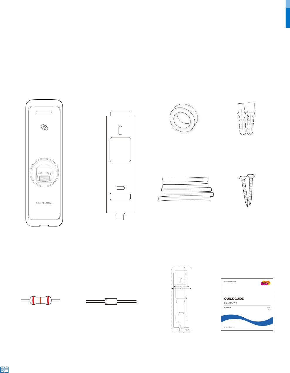
Components
Components may vary according to the installation environment.
Note
BioEntry W2
Bracket
PVC anchor
(2 EA)
Fixing screw
(2 EA)
Diode
(1 EA)
120 Ω resistor
(1 EA)
Drilling template
Quick guide
Ferrite core
(1 EA)
Heat shrink tubes
Introduction
6
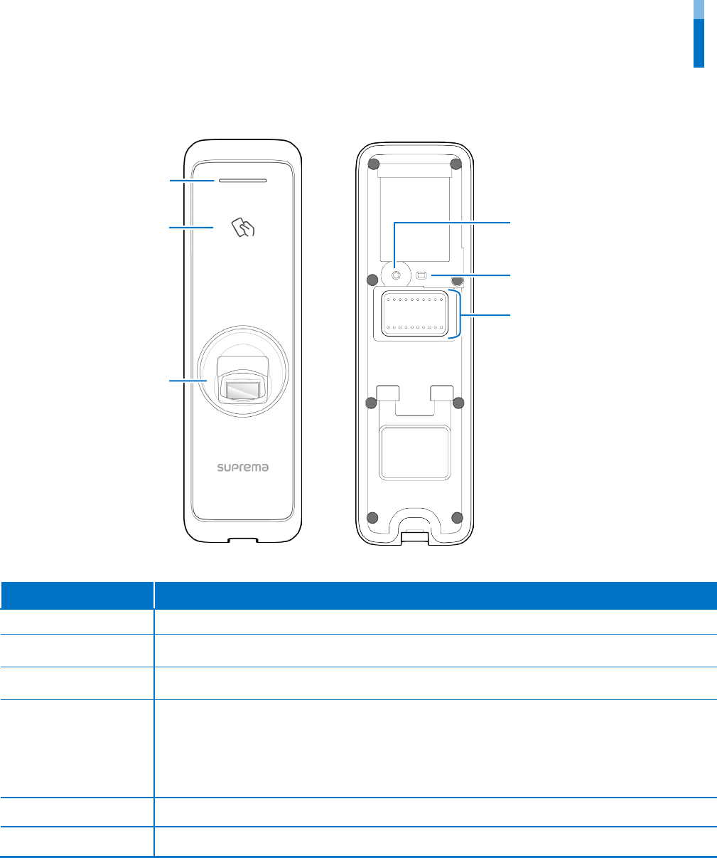
Name and function of each part
Name Feature
LED lamp Indicates the operational status of the product with the color of the LED lamp.
RF card authentication
unit
Reads RF cards for entering and exiting.
Fingerprint
authentication unit
Reads fingerprints placed on it for entering and exiting.
Cable
• TTL input cable
• Wiegand input or output cable
• Power cable
• RS485 cable
• Ethernet connector
•
Relay output cable
LED lamp for Network Shows the status of the network connection.
Network reset button Resets the network configuration. For details, refer to the Resetting Network Setting.
Fingerprint
authentication unit
LED lamp
RF card
authentication unit
LED status indicator for Net
work
Network reset button
Cable
Introduction
7
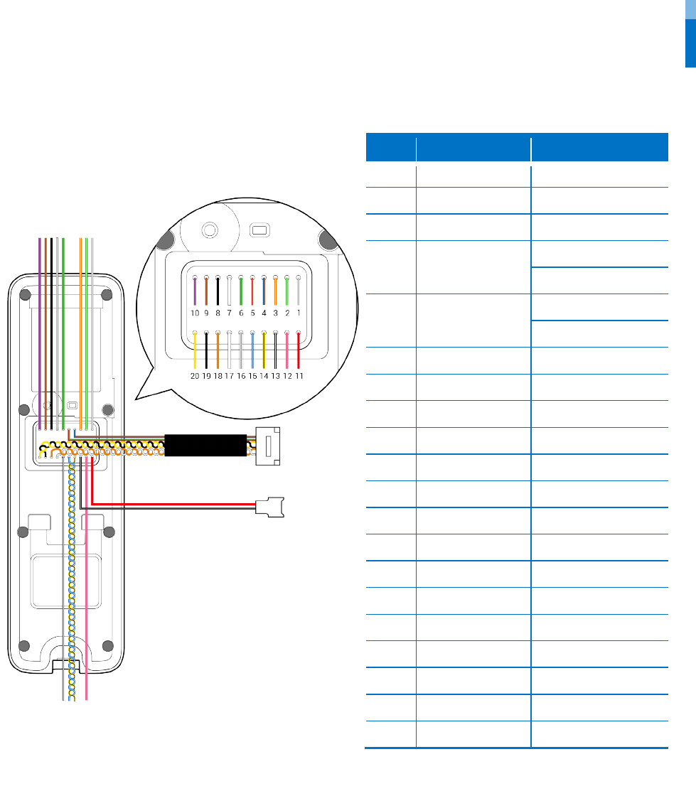
Cables and connectors
Pin
Name
Color
1
RLY NO
Gray (White stripe)
2
RLY COM
Green (White stripe)
3
RLY NC
Orange (White stripe)
4 VB2
Blue
Brown
5 VB1
Red
Green
6
WG D0
Green
7
WG D1
White
8
WG GND
Black
9
TTL IN 1
Brown
10
TTL IN 0
Purple
11
PWR +VDC
Red
12
Not Connected
Pink
13
PWR GND
Black (White stripe)
14
485 TRXN
Yellow (Black stripe)
15
485 TRXP
Blue (White stripe)
16
485 GND
White (Black stripe)
17
ENET TXP
White
18
ENET TXN
Orange
19
ENET RXP
Black
20
ENET RXN
Yellow
Introduction
8
How to enroll a fingerprint
In order to improve the fingerprint authentication rate, register the fingerprint correctly. BioEntry W2 can recognize a fingerprint even if the
angle and position of a user's fingerprint input change. If you register the fingerprint with attention to the following matters, the
authentication rate can be improved.
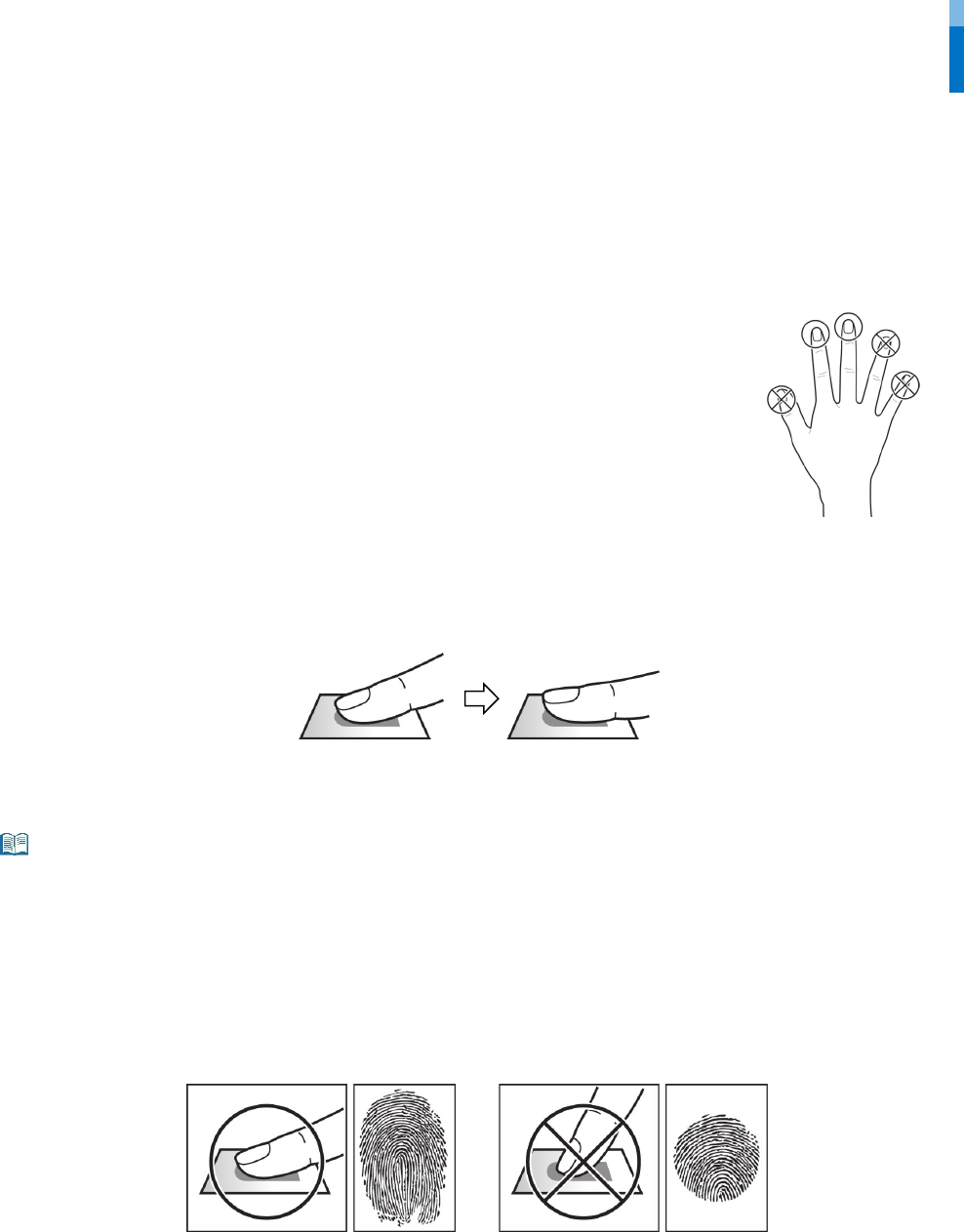
Selecting a finger for fingerprint input
• In preparation for the case that the fingerprint of a specific finger cannot be used, for example if
the user is lifting a load with one hand or a finger gets hurt, up to 10 fingerprints for each user can
be registered.
• In the case of a user whose fingerprint cannot be recognized well, the authentication rate can be
improved by enrolling the same finger twice repeatedly.
• If a finger has a cut or the fingerprint is blurry, select another finger for the fingerprint.
• It is recommended to use the index finger or the middle finger when scanning the fingerprint. The
authentication rate can be reduced if it is difficult to place another finger at the center of
fingerprint sensor accurately.
Fingerprint enroll method
1
Place the finger with the fingerprint to be registered on the fingerprint authentication unit and press the finger gently for better
authentication.
2
After a beep sounds, scan the finger
print of the registered finger again (scan the fingerprint of a finger to be registered twice).
Cautions for enrolling a fingerprint
When a fingerprint is recognized, it is compared with the initially registered fingerprint, so the initial fingerprint enroll is the most important. Pay
attention to the following matters when enrolling the fingerprint.
• Place the finger deep enough to contact with the sensor completely.
• Place the center of the fingerprint in the center of the sensor.
• If a finger has a cut or the fingerprint is blurry, select another finger for the fingerprint.
• Scan the fingerprint correctly without moving according to the instruction on the screen.
• If you make the finger upright so that the contact area with the sensor has decreased or the angle of finger has warped, fingerprint authentication
may not be performed.
When the fingerprint recognition fails
BioEntry W2 can recognize a fingerprint regardless of a change of season or finger condition. However, the authentication rate may vary according to
the external environment or fingerprint input method.
If the fingerprint authentication cannot be done smoothly, it is recommended to take the following measures.
• If the finger is smeared with water or sweat, dry off the finger and then scan the finger.
• If the finger is too dry, blow your breath on the fingertips and then scan the finger.
• If the finger has a cut, register the fingerprint of another finger.
• The initially registered fingerprint often may have not been scanned correctly, so register the fingerprint again according to ‘Cautions for enrolling
a fingerprint’.
Note
Installation
9
Installation
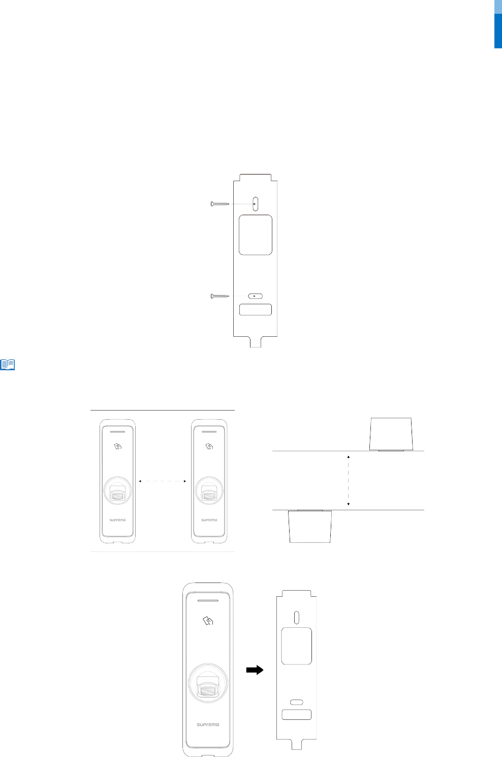
Fixing the bracket and the product
1 Determine the correct position to install the bracket using the provided drilling template. Fix the bracket firmly using fixing screws
through the bracket to the position where BioEntry W2 will be installed.
• If installing BioEntry W2 on a concrete wall, drill holes, insert PVC anchors, and fix them with fixing screws.
• To avoid RF interference, a minimum separation distance must be maintained.
2 Install BioEntry W2 onto the fixed bracket.
Wall
Wall
30 cm
30 cm
Note
Installation
10
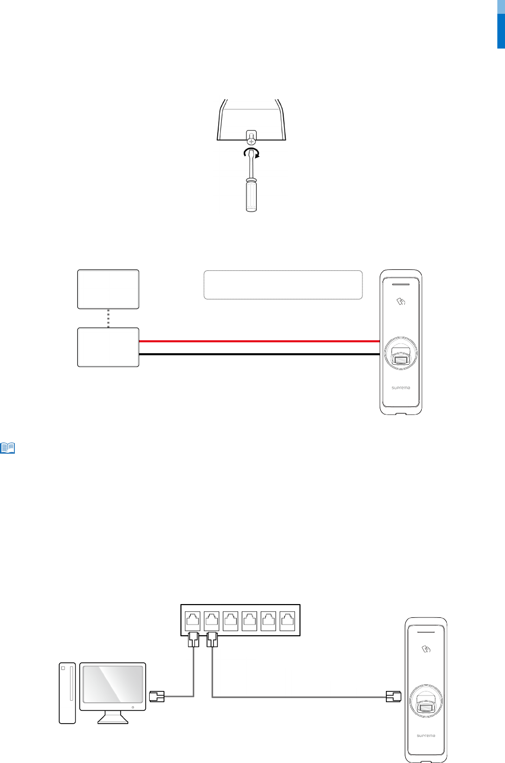
3 Connect BioEntry W2 to the bracket by rotating the product fixing screw.
Power supply connection
• Use a power supply adaptor of DC 12 V (± 10%) with a minimum of 1,500 mA which has obtained the approval of IEC/EN 60950-1. If you wish to
connect and use another device to the power supply adaptor, you should use an adaptor with a current capacity which is the same or larger than
the total power consumption required for the terminal and another device.
• Use a separate power supply for Secure I/O 2, the electric lock, and the BioEntry W2 respectively. If connecting and using the power supply to these
devices together, the devices may malfunction.
Network connection
TCP/IP
LAN connection (connecting to a hub)
You can connect the product to a hub using a general type CAT-5 cable.
BioEntry W2
Hub
PC
Note
BioEntry W2
11 - PWR +VDC Red
13 - PWR GND Black (White stripe)
UPS
(Optional)
DC
power
11
13
Installation
11
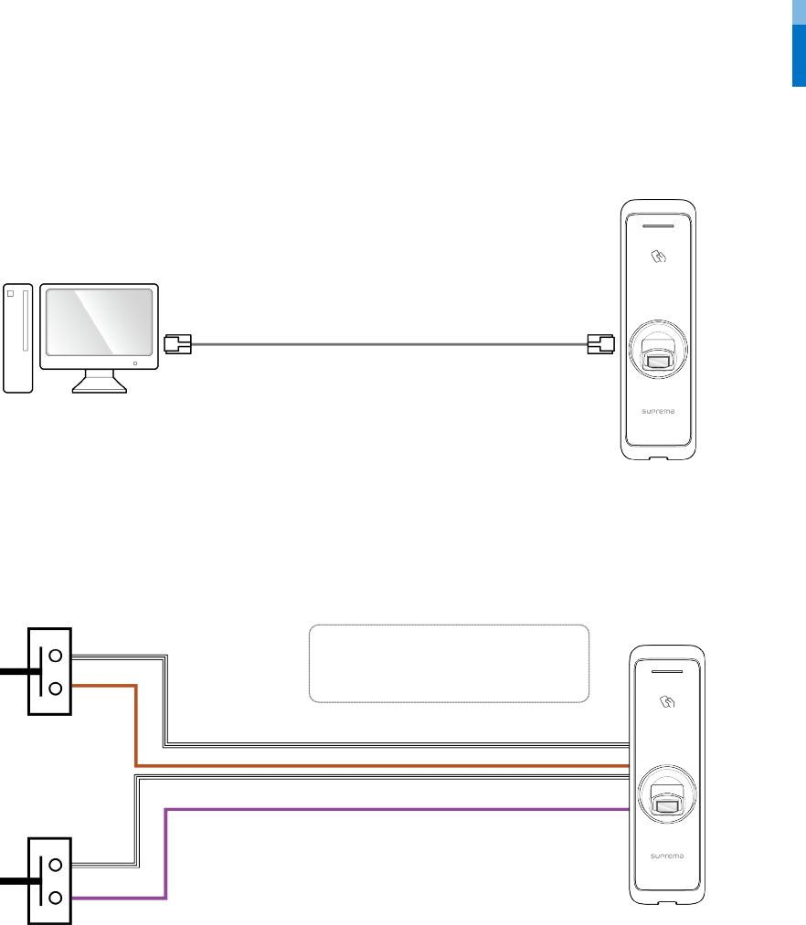
LAN connection (connecting to a PC directly)
BioEntry W2 has an automatic MDI/MDIX function so that it can be connected to a PC directly using a normal straight type CAT-5 cable, not
a cross cable.
TTL input connection
BioEntry W2
9 - TTL IN 1 Brown
10 - TTL IN 0 Purple
16 - 485 GND White (Black stripe)
16
9
10
Door sensor
Door button
16
BioEntry W2
PC
Installation
12
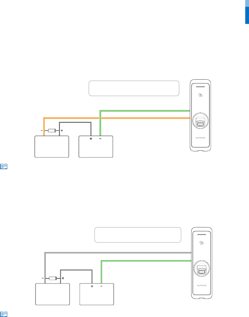
Relay connection
Fail Safe Lock
In order to use the Fail Safe Lock, connect N/C relay as shown in the figure below. There is normally a current flowing through the relay for
the Fail Safe Lock. When the relay is activated, blocking the current flow, the door will open. If the power supply to the product is cut off due
to a power failure or an external factor, the door will open.
• Install a diode at both sides of the door lock wire as shown in the figure to protect the relay from the reverse current, which occurs when the door
lock operates.
• Take caution of the installation direction of the diode. Install the diode close to the door lock.
• Use a separate power supply for BioEntry W2 and the door lock.
Fail Secure Lock
In order to use the Fail Secure Lock, connect N/O relay as shown in the figure below There is normally no current flowing through the relay
for the Fail Secure Lock. When the current flow is activated by the relay, the door will open. If the power supply to the product is cut off due
to a power failure or an external factor, the door will lock.
• Install a diode at both sides of the door lock wire as shown in the figure to protect the relay from the reverse current, which occurs when the door
lock operates.
• Take caution of the installation direction of the diode. Install the diode close to the door lock.
• Use a separate power supply for BioEntry W2 and the door lock.
Note
BioEntry W2
Deadbolt /
Door strike
DC
power
2
1
1 - RLY NO Gray (White stripe)
2 - RLY COM Green (White stripe)
Note
BioEntry W2
2 - RLY COM Green (White stripe)
3 - RLY NC Orange (White stripe)
Deadbolt /
Door strike
DC
power
2
3
Installation
13
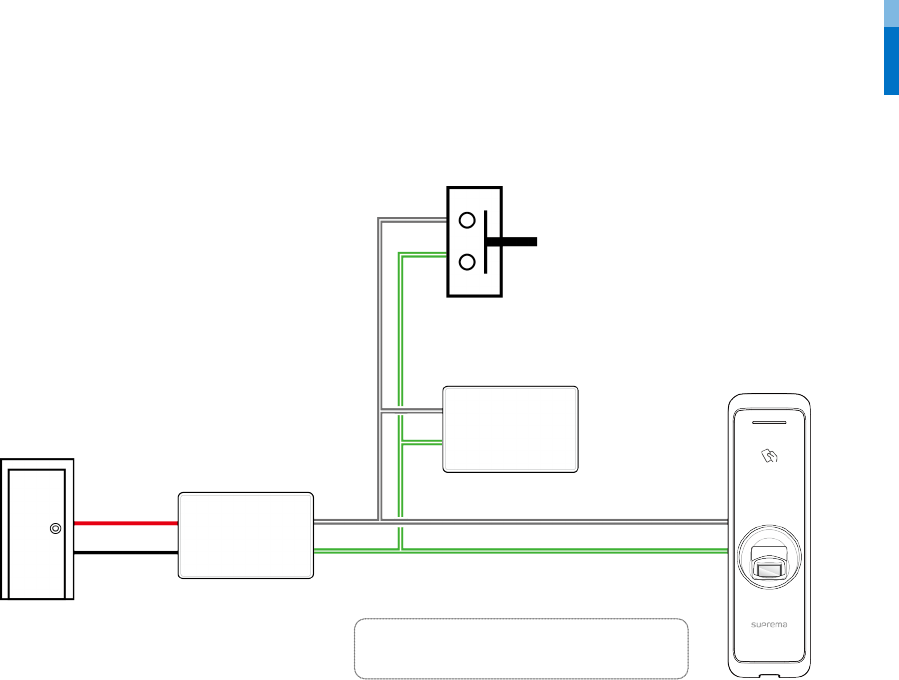
Automatic door connection
BioEntry W2
Automatic door
Controller
Sensor
Door Lock
Door button
1 - RLY NO Gray (White stripe)
2 - RLY COM Green (White stripe)
2
1
Installation
14
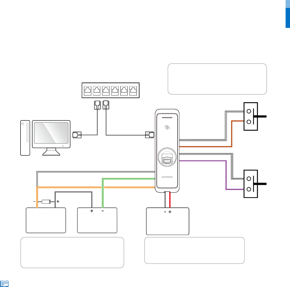
Connecting as a standalone
BioEntry W2 can be connected to the door lock, door button, and door sensor directly without connecting a separate I/O device.
• BioEntry W2 can be used as a multi-door controller with the slave devices with the RS485 cable. The slave devices are used as dummy readers and
authentication is performed in the master device.
• If Xpass is connected to the master device, only card authentication can be used.
• The maximum number of slave devices available to connect varies according to the authentication method, number of users, and number of
devices. Also note that the number of slave devices affects the fingerprint authentication speed.
• A master device can control 31 slave devices. The bandwidth of RS485 allows for up to 7 fingerprint authentication devices to be connected.
• For more information, contact the Suprema technical support team (support@suprema.co.kr).
Note
BioEntry W2
PC
Relay
Door sensor
Door button
1
2
3
11
13
DC
power
DC
power
Deadbolt /
Door strike
Hub
Fail Safe Lock
Fail Secure Lock
or
Power
16
9
16
10
TTL connection
9 - TTL IN 1 Brown
10 - TTL IN 0 Purple
16 - 485 GND White (Black stripe)
Relay connection
1 - RLY NO Gray (White stripe)
2 - RLY COM Green (White stripe)
3 - RLY NC Orange (White stripe)
Power supply connection
11 - PWR +VDC Red
13 - PWR GND Black (White stripe)
Installation
15
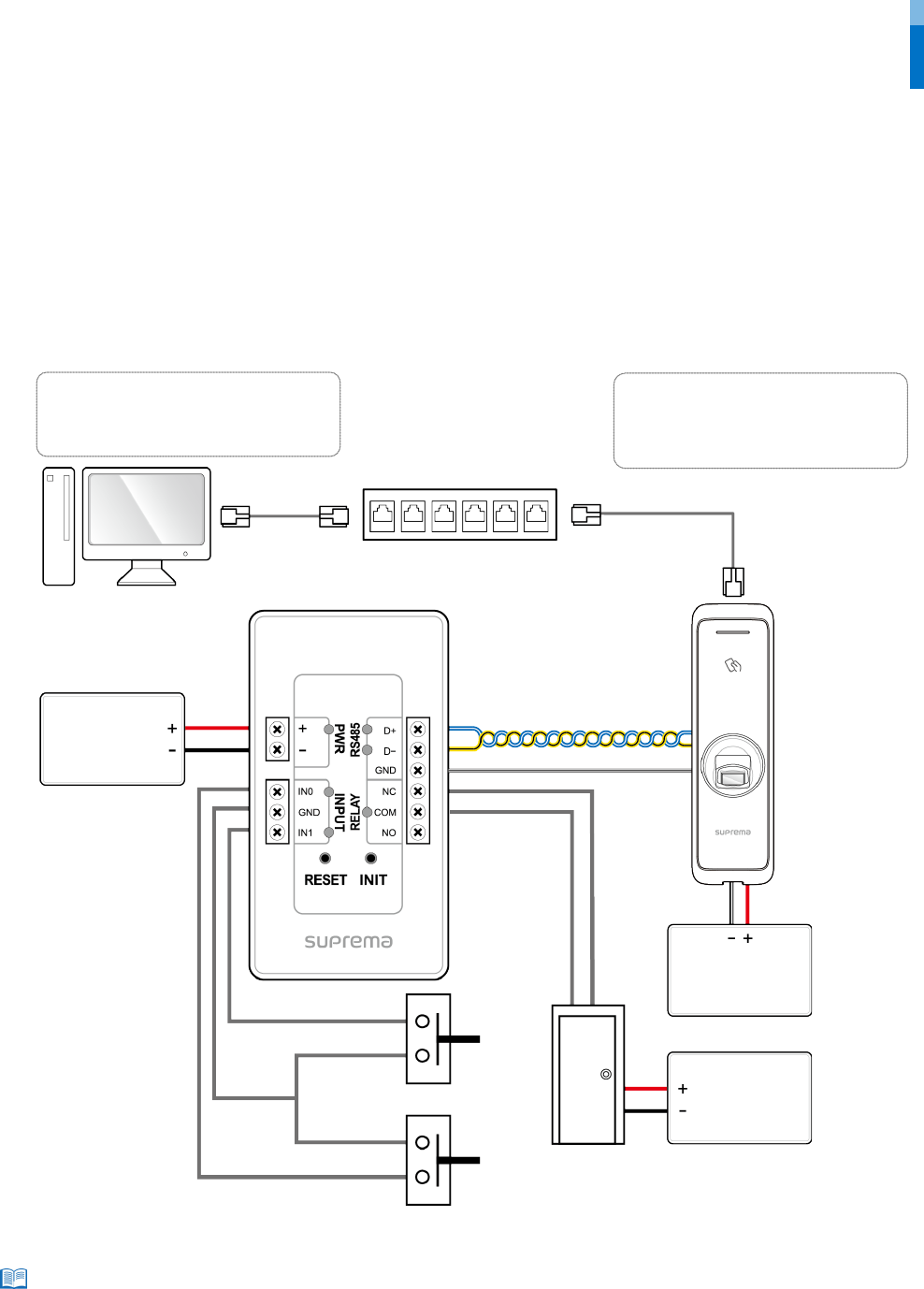
Connecting to Secure I/O 2
Secure I/O 2 is an I/O device, can be connected to BioEntry W2 with the RS-485 cable. Security can be maintained even if the connection
between BioEntry W2 and Secure I/O 2 has been lost or the power supply to BioEntry W2 has been shut off due to external factors.
• Use an AWG24 twisted pair with a maximum length of 1.2 km for the RS-485 cable.
• If connecting with a RS-485 daisy chain, connect the termination resistor (120 Ω) to both ends of the daisy chain connection. If
connected to the middle line, the signal level becomes smaller and the communication performance will deteriorate. Make sure to
connect it to both ends of the daisy chain connection.
• BioEntry W2 can be used as a multi-door controller with the slave devices with the RS485 cable. The slave devices are used as dummy readers and
authentication is performed in the master device.
• If Xpass is connected to the master device, only card authentication can be used.
• The maximum number of slave devices available to connect varies according to the authentication method, number of users, and number of
devices. Also note that the number of slave devices affects the fingerprint authentication speed.
• A master device can control 31 slave devices. The bandwidth of RS485 allows for up to 7 fingerprint authentication devices to be connected.
• For more information, contact the Suprema technical support team (support@suprema.co.kr).
Note
BioEntry W2
PC
Secure I/O 2
Hub
Door button
Door sensor
Power
RS-485 connection
14 - 485 TRXN Yellow (Black stripe)
15 - 485 TRXP Blue (White stripe)
16 - 485 GND White (Black stripe)
14
13
15
Door lock
DC
power
DC
power
DC
power
11
16
Power supply connection
11 - PWR +VDC Red
13 - PWR GND
Black (White stripe)
RS-485
Installation
16
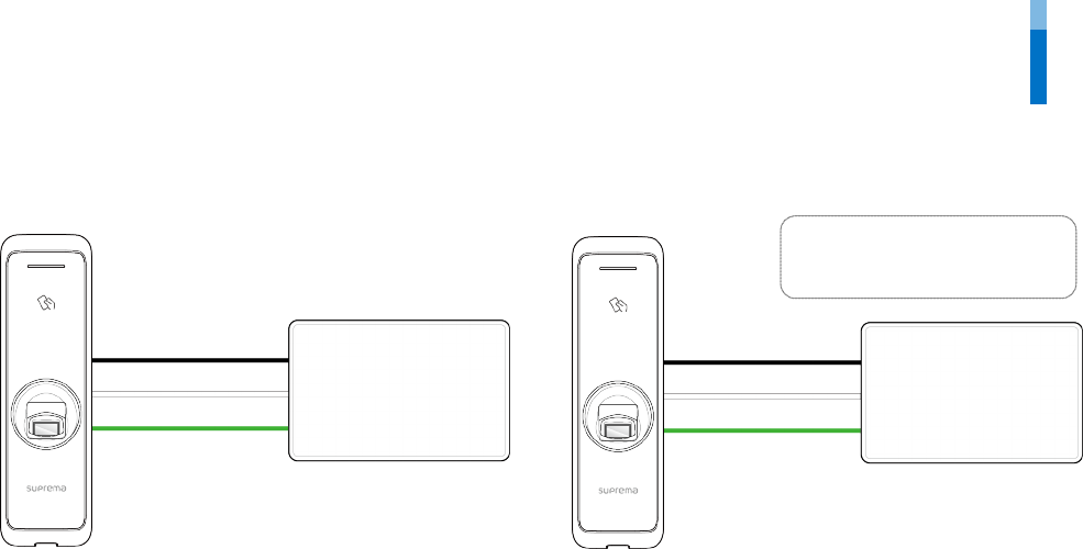
Wiegand connection
Resetting Network Settings
1 Turn the power on.
2 Press the network reset button on the rear of device until the device restart automatically.
3 Connect the device with default values.
•TCP/IP address: DHCP address assignment (If DHCP address assignment is failed, 169.254.0.1 will be set.)
•Server mode: Disabled
•RS-485: PC connection, 115200 bps
4 Change the TCP/IP address or RS-485 information.
5 Turn the power off later on and then check the network setting is properly.
BioEntry W2
RFID reader
6 - WG D0 Green
7 - WG D1 White
8 - WG GND Black
8
7
6
8
7
6
Use as a Wiegand input device
Use as a Wiegand output device
Control device
BioEntry W2

Product specifications
17
Product specifications
Category Feature Specification
Credential
Biometric
Fingerprint
RF Option
125 KHz EM/HID Proxy,
13.56 MHz MIFARE/DESFire/DESFire EV1/Felica/NFC/iClass
RF read range
*
MIFARE/DESFire/EM/HID Proxy/iClass/ISO15693 : 50 mm, Felica: 30 mm
General
CPU
1.2 GHz Quad Core
Memory
2GB Flash + 256 MB RAM
LED
Multi-color
Sound
Multi-tone Buzzer
Operating temperature
-20°C - 50°C
Storage temperature
-40°C - 70°C
Operating humidity
0% - 80%, non-condensing
Storage humidity
0% - 90%, non-condensing
Dimension (W x H x D)
50 mm x 172 mm x 43.5 mm (Bottom) / 38.2 mm (Top)
Weight
Device: 251g
Bracket: 43g (Including washer and bolt)
IP rating
IP67
IK rating
IK08
Certificates
CE, FCC, KC, RoHS, REACH, WEEE
Fingerprint
Image dimension
272 x 320 pixels
Image bit depth
8bit, 256 grayscale
Resolution
500 dpi
Template
SUPREMA / ISO 19794-2 / ANSI 378
Extractor / Matcher
MINEX certified and compliant
LFD
Supported
Capacity
Max. User (1:1)
500,000
Max. User (1:N)
100,000
Max. Template (1:1)
1,000,000
Max. Template (1:N)
200,000
Max. Text Log
1,000,000
Interface
Ethernet
Supported (10/100 Mbps, auto MDI/MDI-X)
RS-485
1ch Master / Slave (Selectable)
Wiegand
1ch Input / Output (Selectable)
TTL input
2ch Input
Relay
1 Relay
PoE
Supported
Tamper
Supported
Electrical
Power
Voltage: DC 12 V
Current: Max. 600 mA
Switch input VIH
Min. 3 V
Max. 5 V
Switch input VIL
Max. 1 V
Switch Pull-up resistance 4.7 kΩ (The input ports are pulled up with 4.7 kΩ.)
Wiegand output VOH
More than 4.8 V
Wiegand output V
OL
Less than 0.2 V
Wiegand output Pull-up
resistance
Internally pulled up with 1 kΩ
Relay
Voltage: Max. 30VDC
Current: 1A
* RF read range will vary depending on the installation environment.
Product specifications
18
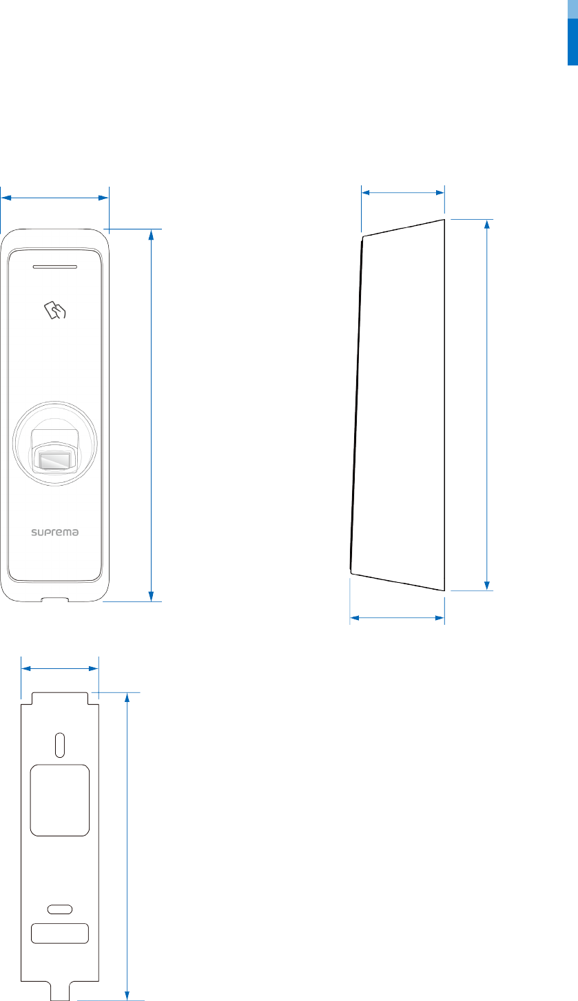
Dimensions
(Unit: mm)
50
172
38.2
43.5
172
39.4
156.8

FCC Compliance Information
19
FCC Compliance Information
THIS DEVICE COMPLIES WITH PART 15 OF THE FCC RULES.
Operation is subject to the following two conditions:
(1) This device may not cause harmful interference, and
(2) This device must accept any interference received, including interference that may cause undesired operation.
Note: This equipment has been tested and found to comply with the limits for a Class B digital device, pursuant to part 15 of the FCC Rules.
These limits are designed to provide reasonable protection against harmful interference in a residential installation. This equipment
generates, uses, and can radiate radio frequency energy and, if not installed and used in accordance with the instructions, may cause
harmful interference to radio communications. However, there is no guarantee that interference will not occur in a particular installation. If
this equipment does cause harmful interference to radio or television reception, which can be determined by turning the equipment off
and on, the user is encouraged to try to correct the interference by one or more of the following measures:
•Reorient or relocate the receiving antenna.
•Increase the separation between the equipment and receiver.
•Connect the equipment into an outlet on a circuit different from that to which the receiver is connected.
•Consult the dealer or an experienced radio/TV technician for help.
Modifications not expressly approved by the manufacturer could void the user's authority to operate the equipment under FCC rules.
This appliance and its antenna must not be co-located or operation in conjunction with any other antenna or transmitter.
A minimum separation distance of 20 cm must be maintained between the antenna and the person for this appliance to satisfy the RF
exposure requirements.

Appendix
20
Appendix
Escape clause
•The information in this manual is provided with regard to the Suprema's products.
•The right to use is acknowledged only for products included in the terms and conditions of the sales agreement guaranteed by
Suprema. The right of license to other intellectual property rights not discussed in this manual is not acknowledged.
•Suprema does not guarantee or hold responsibility for the suitability and commerciality of the product for a specific purpose, or the
infringement of patent, copyright, or other intellectual property rights with regard to sales or usage of Suprema's products.
•Do not use the product of Suprema under the situations related to medical, rescue of human lives, or maintenance of life, as a person
may get injured or lose his/her life due to product malfunction. If an accident occurs while a consumer is using the product under the
situations described as examples above, employees, subsidiaries, branches, affiliated companies and distributors of Suprema do not
accept responsibility nor will they reimburse for all related direct and indirect expenses or expenditure including attorney fees even if
the consumer has discovered any shortcomings in the product design or manufacturing process and claims this as a significant fault.
•Suprema may modify the product size and specifications at any time without proper notice in order to improve the safety, function and
design of the product. Designers must keep in mind that functions or descriptions indicated as "to be implemented" or "undefined"
may change at any time. Suprema will implement or define such functions or descriptions in the near future and Suprema accepts no
responsibility for compatibility issues and any other problems arising from such compatibility issues.
•If you wish to obtain the newest specifications before ordering the product, contact Suprema through a Sales Representative or local
distributor of Suprema.
Copyright notice
The copyright of this document is vested in Suprema. The rights of other product names, trademarks and registered trademarks are vested
in each individual or organization that owns such rights.

www.supremainc.com
www.supremainc.com