Suprema BIOENTRYTC Access Reader User Manual BioEntry Installation Guide 0 96c
Suprema Inc. Access Reader BioEntry Installation Guide 0 96c
Suprema >
Users Manual

BioEntry™ Installation Guide
BioEntry™ Smart / Pass
Ver. 0.96c
Suprema Inc and BioEntry™ are registered trademarks of Suprema Inc. All
rights reserved. No part of this work covered by the copyright hereon may be
reproduced or copied in any form or by any means - graphics, electronic, or
mechanical, including photocopying, recording, taping, or information and
retrieval systems - without written permission of Suprema Inc. Any software
furnished under a license may be used or copied only in accordance with
the terms of such license.
Suprema Inc reserves the right to modify or revise all or part of this
document without notice and shall not be responsible for any loss, cost or
damage, including consequential damage, caused by reliance on these
materials.
Copyright © 2005 by Suprema Inc.

BioEntry Smart/Pass BioEntry Installation Guide 2
Copyright © 2005 by Suprema Inc. http://www.supremainc.com
Suprema Warranty Policy
Suprema warrants to buyer, subject to the limitations set forth below, that
each product shall operate in substantial accordance with the published
specifications for such product for a period of one (1) year from the date of
shipment of the products (“Warranty Period”). If buyer notifies Suprema in
writing within the Warranty Period of any defects covered by this warranty,
Suprema shall, at its option, repair or replace the defective product which
is returned to Suprema within Warranty Period, freight and insurance
prepaid by buyer. Such repair or replacement shall be Suprema’s
exclusive remedy for breach of warranty with respect to the Product. This
limited warranty shall not extend to any product which has been: (i)
subject to unusual physical or electrical stress, misuse, neglect, accident
or abuse, or damaged by any other external causes; (ii) improperly
repaired, altered or modified in any way unless such modification is
approved in writing by the Supplier; (iii) improperly installed or used in
violation of instructions furnished by Suprema.
Suprema shall be notified in writing of defects in the RMA report supplied
by Suprema not later than thirty days after such defects have appeared
and at the latest one year after the date of shipment of the Products. The
report should give full details of each defected product, model number,
invoice number and serial number. No product without RMA (Return
Material Authorization) number issued by Suprema may be accepted and
all defects must be reproducible for warranty service.
Except as expressly provided in the first paragraph, the products are
delivered to Suprema without warranty of any kind, express or implied,
including warranties or merchantability, fitness for a particular purpose.

BioEntry Smart/Pass BioEntry Installation Guide 3
Copyright © 2005 by Suprema Inc. http://www.supremainc.com
Disclaimers
Information in this document is provided in connection with Suprema
products. No license, express or implied, by estoppel or otherwise, to any
intellectual property rights is granted by this document. Except as provided
in Suprema’s Terms and Conditions of Sale for such products,
Suprema assumes no liability whatsoever, and Suprema disclaims any
express or implied warranty, relating to sale and/or use of Suprema
products including liability or warranties relating to fitness for a particular
purpose, merchantability, or infringement of any patent, copyright or other
intellectual property right.
Suprema products are not intended for use in medical, life saving, life
sustaining applications, or other applications in which the failure of the
Suprema product could create a situation where personal injury or death
may occur. Should Buyer purchase or use Suprema products for any
such unintended or unauthorized application, Buyer shall indemnify and
hold Suprema and its officers, employees, subsidiaries, affiliates, and
distributors harmless against all claims, costs, damages, and expenses,
and reasonable attorney fees arising out of, directly or indirectly, any claim
of personal injury or death associated with such unintended or
unauthorized use, even if such claim alleges that Suprema was negligent
regarding the design or manufacture of the part.
Suprema reserves the right to make changes to specifications and
product descriptions at any time without notice to improve reliability,
function, or design. Designers must not rely on the absence or
characteristics of any features or instructions marked "reserved" or
"undefined." Suprema reserves these for future definition and shall have
no responsibility whatsoever for conflicts or incompatibilities arising from
future changes to them.
Please contact Suprema, local Suprema sales representatives or local
distributors to obtain the latest specifications and before placing your

BioEntry Smart/Pass BioEntry Installation Guide 4
Copyright © 2005 by Suprema Inc. http://www.supremainc.com
product order.
Note: Third-party brands and names are the property of their respective
owners.
About the BioEntry™ Series
BioEntry™ is an advanced biometric access reader equipped with award
winning fingerprint recognition engine and standard wiegand interface.
BioEntry™ can practically replace legacy and simple readers and be
instantly added onto existing access control systems as well as new
installations.
BioEntry™ Smart is a fingerprint smart card reader that seamlessly
integrates fingerprint and smart card reader into one device. BioEntry™
Smart is designed to replace existing access readers like proximity or
magnetic readers without additional wiring. Fingerprint template is stored
in each user’s smart card and there is no need to store fingerprint data in
a reader itself. This eliminates the burden of template management and
networking readers.
BioEntry™ Pass is a fingerprint access reader equipped with fast one to
many fingerprint identification engine. Enrolled with more than hundreds of
users, identification can be done in less than one second.
Following the unique feature of Suprema’s famous UniFinger™ fingerprint
identification modules, BioEntry™ also provides customers with multiple
choices of fingerprint sensors including optical, capacitive and thermal
sensors.

BioEntry Smart/Pass BioEntry Installation Guide 5
Copyright © 2005 by Suprema Inc. http://www.supremainc.com
About Suprema Inc
Suprema is a leading biometric company offering core fingerprint
technologies for embedded and PC applications. Suprema’s fingerprint
products include low cost standalone OEM modules, access control
readers, USB fingerprint scanners and fingerprint algorithm SDK.
Suprema’s fingerprint recognition algorithm was proved to be world top
level by ranking first in the 3
rd international Fingerprint Verification
Competition (FVC2004) with the lowest error rate in light category.
Suprema’s fingerprint products have been sold to more than 50 different
countries and are being used in various applications. For more information
on Suprema’s technologies and products, Please visit Suprema’s website
(http://www.supremainc.com) or contact by e-mail
(sales@supremainc.com).
About This Guide
This is an introduction to the installation of BioEntry™ Smart and Pass.
This guide describes how to install, examples for BioEntry™ and technical
specifications. The purpose of this guide is to provide instructions on using
BioEntry™ Smart and Pass and troubleshooting minor problems.

BioEntry Smart/Pass BioEntry Installation Guide 6
Copyright © 2005 by Suprema Inc. http://www.supremainc.com
Contents
1. Before you start with BioEntry™ ............................................................................9
1.1. Included items......................................................................................................... 9
1.2. Required items........................................................................................................ 9
1.3. Optional items......................................................................................................... 9
2. Installing BioEntry™ .............................................................................................10
2.1. Connecting wires................................................................................................... 10
2.2. Power connection...................................................................................................11
2.3. Connecting to a Wiegand compatible reader............................................................11
2.4. Connecting to a Wiegand compatible access controller............................................ 12
2.5. Connecting to the host computer............................................................................ 12
2.5.1. Connecting via RS-232C interface.....................................................................12
2.5.2. Connecting via RS-485 interface for a full duplex BioEntry network system ................12
2.5.3. Connecting via RS-485 interface for a half duplex BioEntry network system...............13
2.5.4. Connecting via auxiliary interface......................................................................14
2.6. Disassembling....................................................................................................... 15
2.7. Mounting back plate.............................................................................................. 16
2.8. Reassembling the BioEntry.................................................................................... 16
2.9. Installing the BioEntry™ Admin Software....
오류
!
책갈피가
정의되어
있지
않습니다
.
3. Examples for BioEntry™ installation....................................................................17
3.1. Building a new system ........................................................................................... 17
3.1.1. Installing BioEntry Pass...................................................................................17
3.1.2. Installing BioEntry Smart .................................................................................17
3.2. Adding BioEntry to existing access control system................................................... 18
4. Specifications........................................................................................................20
4.1. Fingerprint Authentication Specifications ................................................................. 20
4.1.1. Fingerprint Authentication Performance..............................................................20
4.1.2. Fingerprint Sensor Specifications ......................................................................20

BioEntry Smart/Pass BioEntry Installation Guide 7
Copyright © 2005 by Suprema Inc. http://www.supremainc.com
4.1.3. Data storage.................................................................................................20
4.2. Mechanical Specifications...................................................................................... 20
4.2.1. Operating range............................................................................................20
4.2.2. Absolute Maximum Ratings .......................
오류
!
책갈피가
정의되어
있지
않습니다
.
4.2.3. Electrical DC characteristics.......................
오류
!
책갈피가
정의되어
있지
않습니다
.

BioEntry Smart/Pass BioEntry Installation Guide 8
Copyright © 2005 by Suprema Inc. http://www.supremainc.com
Figures
Figure 1> A full duplex BioEntry network.............................................................13
Figure 2> A half duplex BioEntry network.............................................................14
Figure 3> Connecting stereo plug to DB-9 cable ...
오류
!
책갈피가
정의되어
있지
않습니다
.
Figure 4> Auxiliary port.................................
오류
!
책갈피가
정의되어
있지
않습니다
.
Figure 5> Aux. enable switch..........................
오류
!
책갈피가
정의되어
있지
않습니다
.
Figure 6> Removing the screw ........................................................................15
Figure 7> Separating the case.........................................................................15
Figure 8> Installing back plate to the wall.............................................................16
Figure 9> Reassembling the case.....................................................................16
Figure 10> BioEntry connection diagram .............................................................17
Figure 11> Adding BioEntry Pass to existing system................................................19

BioEntry Smart/Pass BioEntry Installation Guide 9
Copyright © 2005 by Suprema Inc. http://www.supremainc.com
1. Before you start with BioEntry™
1.1. Included items
l A BioEntry Smart/Pass unit
l A stereo plug to DB-9 cable
l This Installation Guide
1.2. Required items
l A DC power supply rated at 12V @ 500mA
l An access control panel with Wiegand input port
1.3. Optional items
l A reader with Wiegand output port
BioEntry Smart/Pass BioEntry Installation Guide 10
Copyright © 2005 by Suprema Inc. http://www.supremainc.com
2. Installing BioEntry™
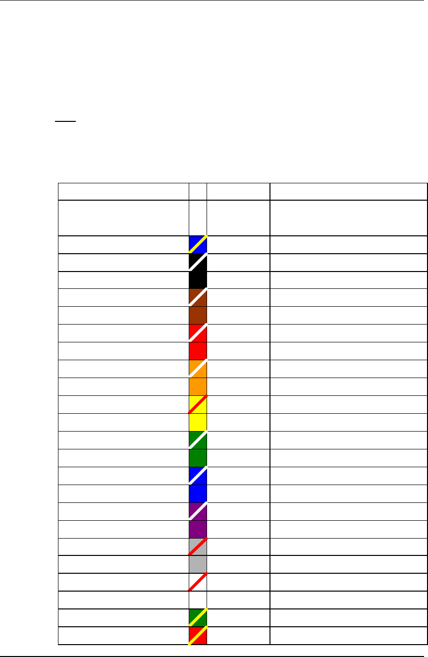
2.1. Connecting wires
The BioEntry is connected to other devices of the security system through the
pigtail cable at the rear side.
See
Table 1 for wire colors and signals.
Wire color Signal Description
Shield (naked wire) EARTH
GND
Ground Earth
Blue with yellow tracer Reserved
Black with white tracer IN0 TTL IN 0
Black IN1 TTL IN 1
Brown with white tracer OUT0 TTL OUT 0
Brown OUT1 TTL OUT 1
Red with white tracer IO_GND GND, for IO signals
Red Reserved
Orange with white tracer WO_GND Wiegand Output, GND
Orange WO_VREF Wiegand Output, VREF
Yellow with red tracer WO_D0 Wiegand Output, Data 0
Yellow WO_D1 Wiegand Output, Data 1
Dark Green with white tracer WI_D0 Wiegand Input, Data 0
Dark Green WI_D1 Wiegand Input, Data 1
Blue with white tracer COM_GND Comm. GND (for RS-232C)
Blue WI_GND Wiegand Input GND
Violet with white tracer RX2 Receive data, RS-232C level
Violet TX2 Transmit data, RS-232C level
Gray with red tracer RX+ RX+, RS-485 level
Gray RX- RX-, RS-485 level
White with red tracer TX+ TX+, RS-485 level
White TX- TX-, RS-485 level
Green with yellow tracer POW_GND Power GND
Red with yellow tracer POW+ Power Input
BioEntry Smart/Pass BioEntry Installation Guide 11
Copyright © 2005 by Suprema Inc. http://www.supremainc.com
Table 1> BioEntry wire colors
Warnings: Care should be taken identifying the wires. Improper wiring may render
permanent damage to the device or personal injury.
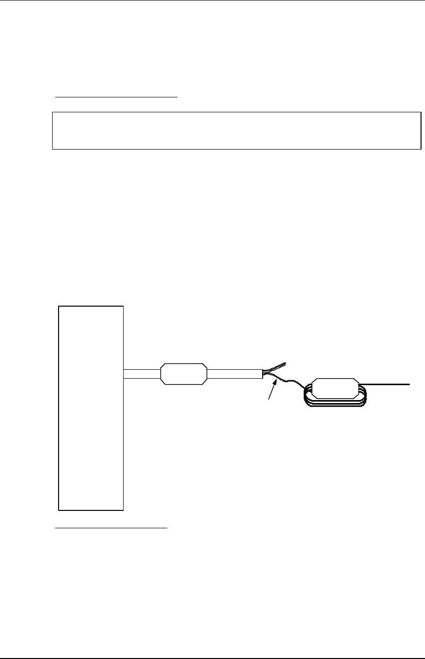
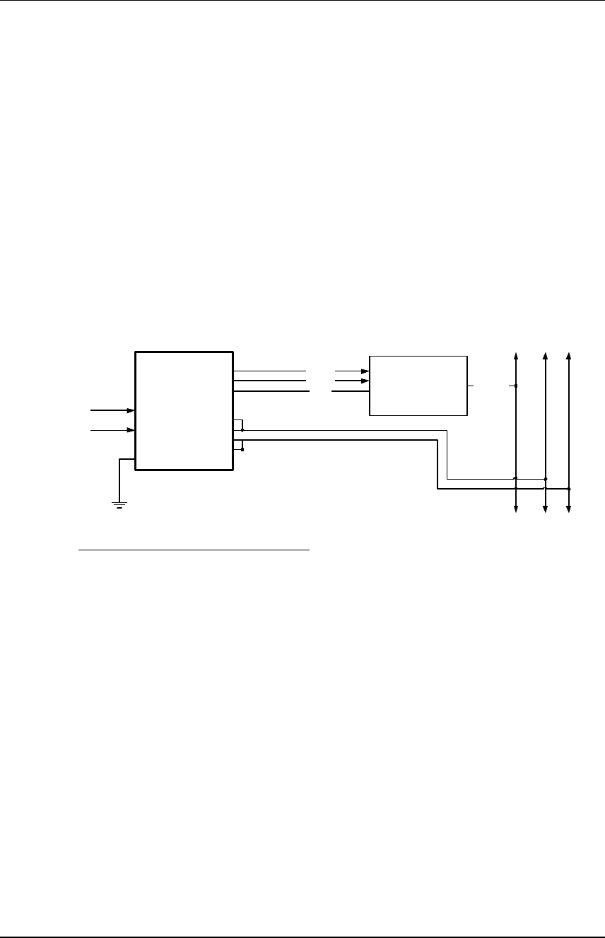
2.2. Power connection
Use ‘POW+’ and ‘POW_GND’ wires to connect BioEntry to a DC supply, rated at
9~24V, 500mA. The power cable should be as short as possible to minimize wire
resistance and emissions.
Additionally, for compliance regulations, a ferrite core should be installed to supply
lines. The installation of this ferrite core is mandatory for R&TTE compliance.
For optimum ESD resistance and safety, please make proper connection of
‘Earth GND’.
BioEntry
Pigtail cable
Ferrite
Core Ferrite
Core
POW+,
POW_GND 3 turns
To power
supply
Other
signals
Figure 1 Power connection
2.3. Connecting to a Wiegand compatible reader
The BioEntry supports Wiegand compatible readers of various formats, including
26bit standard.
Connect ‘WIN_D0’, ‘WIN_D1’ and ‘WIN_GND’ wires to ‘Data 0’, ‘Data 1’ signals
and signal ground of the Wiegand reader, respectively. The input signals can
tolerate voltages up to 12V dc.

BioEntry Smart/Pass BioEntry Installation Guide 12
Copyright © 2005 by Suprema Inc. http://www.supremainc.com
2.4. Connecting to a Wiegand compatible access controller
The BioEntry supports a flexible Wiegand output interface for most access
controllers with Wiegand input ports.
Connect ‘WOUT_D0’, ‘WOUT_D1’ and ‘WOUT_GND’ wires to ‘Data 0’, ‘Data 1’
signals and signal ground of the access controller, respectively. If the access
controller’s input signal level exceeds 5.0V, apply required voltage to
‘WOUT_VREF’ to obtain higher voltage output signals. Be cautious not to
connect ‘WOUT_VREF’ directly to a voltage source, especially when the source
is below 5Vdc. Use a diode and a current limit resistor of a few hundred ohms in
series to prevent excessive currents and damages of the device.
However, ‘WOUT_VREF’ signals can be safely left unconnected as most access
controllers accept 5V Wiegand signals.
2.5. Connecting to the host computer
The BioEntry provides various means to connect to the host computer such as:
being a part of the RS-485 network, direct connection with RS-232C interface and
an auxiliary port for laptops.
2.5.1. Connecting via RS-232C interface
Connect ‘RX2’, ‘TX2’ and ‘COM_GND’ wires to ‘TX’, ‘RX’ and signal ground of
PC’s serial port.
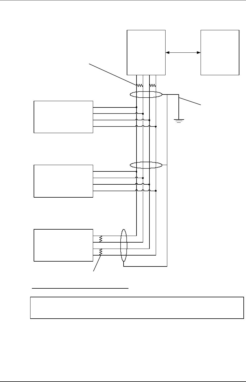
2.5.2. Connecting via RS-485 interface for a full duplex BioEntry network system
Use ‘RX+’, ‘RX-’, ‘TX+’, and ‘TX-’ signals to join a full duplex BioEntry network.
For a full duplex network, two pairs of twisted wires in a shielded cable is needed.
Each signal in all BioEntry devices of the BioEntry network system should be
connected forming a multipoint network. As the PC is the master of the network
system, connect ‘TX+’ and ‘TX-’ signals of the computer to ‘RX+’ and ‘RX-’ of
BioEntry signals, and vice versa(See Figure 2).
At each end of the network, termination resistors of 120ohms should be
connected between ‘+’ and ‘-’ signals for proper impedance matching.
BioEntry Smart/Pass BioEntry Installation Guide 13
Copyright © 2005 by Suprema Inc. http://www.supremainc.com
BioEntry
TX+
TX-
RX+
RX-
BioEntry
TX+
TX-
RX+
RX-
BioEntry
TX+
TX-
RX+
RX-
RS-485
Converter
TX-
TX+
RX-
RX+
PC
RS-232
Termination
Resistors
Termination
Resistors
Connect cable
shield to earth
GND at one
point only
Figure 2> A full duplex BioEntry network
Warnings: To prevent ground loops and avoid communication problems, connect cable
shield to earth GND at only one point.
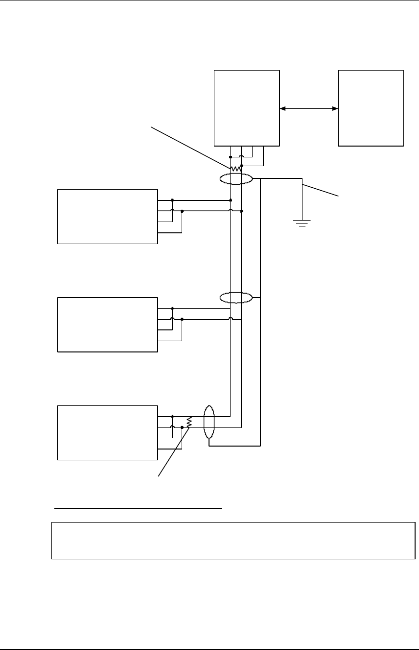
2.5.3. Connecting via RS-485 interface for a half duplex BioEntry network system
For a half duplex network, a pair of twisted wires in a shielded cable is needed.
For every devices in the half duplex network, tie ‘TX+’ with ‘RX+’ and ‘TX-’ with
‘RX-’ locally before connecting to the network(See Figure 3).
BioEntry Smart/Pass BioEntry Installation Guide 14
Copyright © 2005 by Suprema Inc. http://www.supremainc.com
At each end of the network, termination resistors of 120ohms should be
connected between ‘+’ and ‘-’ signals for proper impedance matching.
BioEntry
TX+
TX-
RX+
RX-
BioEntry
TX+
TX-
RX+
RX-
BioEntry
TX+
TX-
RX+
RX-
RS-485
Converter
TX-
TX+
RX-
RX+
PC
RS-232
Termination
Resistor
Termination
Resistor
Connect cable
shield to earth
GND at one
point only
Figure 3> A half duplex BioEntry network
Warnings: To prevent ground loops and avoid communication problems, connect cable
shield to earth GND at only one point.
2.5.4. Connecting via auxiliary interface
The BioEntry series provide an auxiliary port to support connection to laptops,
even if the device is not networked during installation. The user can access and
manage the device with standard RS-232C port.
BioEntry Smart/Pass BioEntry Installation Guide 15
Copyright © 2005 by Suprema Inc. http://www.supremainc.com
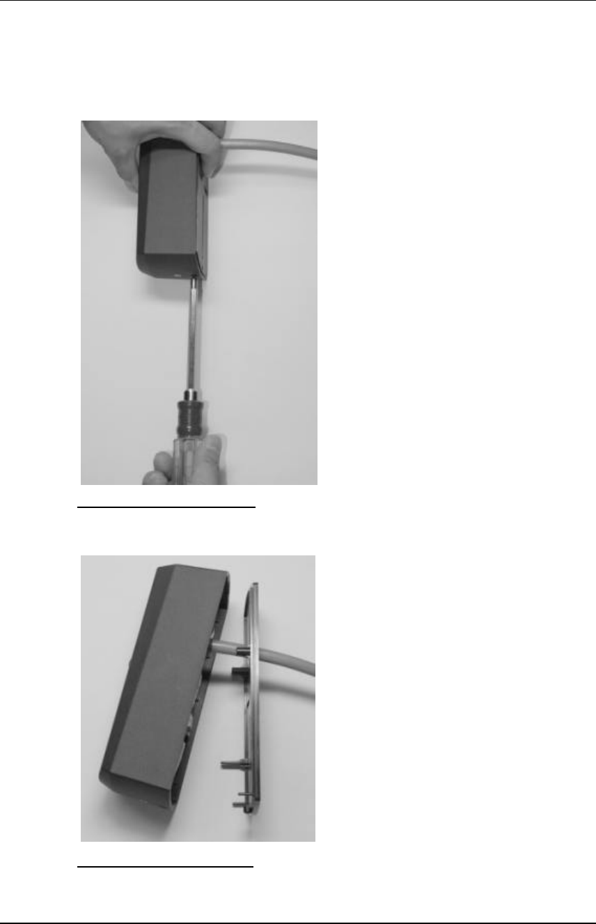
2.6. Disassembling
Remove screw at bottom of the BioEntry.
Figure 4> Removing the screw
Lift bottom of the housing, slide up and carefully remove it.
Figure 5> Separating the case
BioEntry Smart/Pass BioEntry Installation Guide 16
Copyright © 2005 by Suprema Inc. http://www.supremainc.com
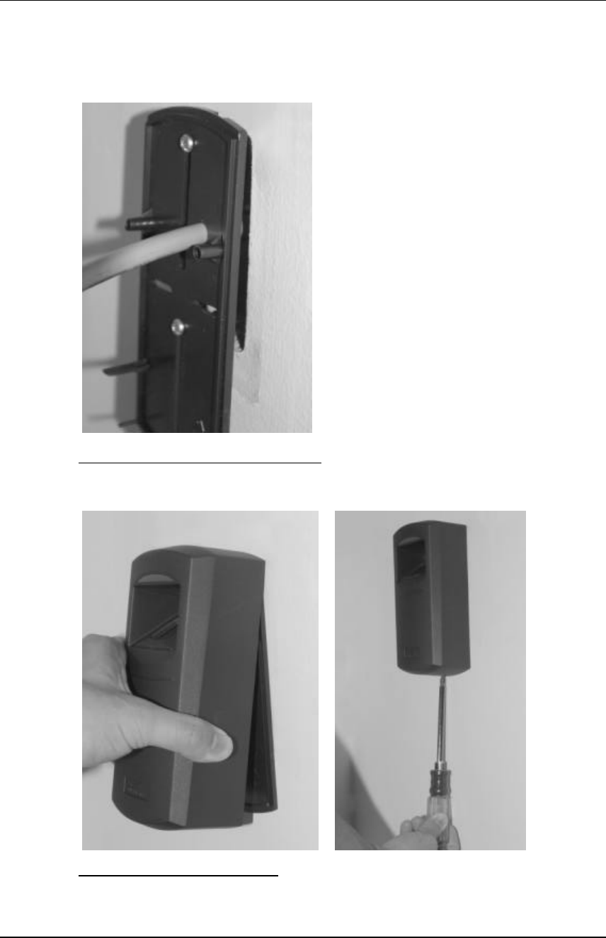
2.7. Mounting back plate
Install back plate to wall surface.
Figure 6> Installing back plate to the wall
2.8. Reassembling the BioEntry
Figure 7> Reassembling the case
BioEntry Smart/Pass BioEntry Installation Guide 17
Copyright © 2005 by Suprema Inc. http://www.supremainc.com
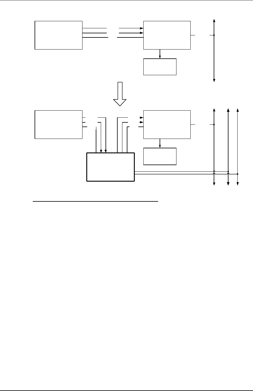
3. Examples for BioEntry™ installation
The BioEntry Smart/Pass offers various interfaces such as Wiegand
input/output, general purpose I/O signals and communication ports that
can be easily implemented to a security system, improving the security
level.
3.1. Building a new system
The BioEntry Smart/Pass is compatible with most access controllers with
Wiegand interface. Building a new access control system with BioEntry is as
simple and easy as with conventional Wiegand readers. In this section, the
system with BioEntry only configuration is explained. The minimal configuration
for BioEntry installation is illustrated in Figure 8.
Data 1Access Controller
Data 0
GND Network
To other controllers
or host computer
TRX+
To other BioEntry readers
or host computer
TRX-
WO_D0
WO_D1
WO_GND
TX+
RX+
RX-
TX-
EARTH
BioEntry
POW_GND
POW+
9~24Vdc
(Optional for BioEntry Smart)
Figure 8> BioEntry connection diagram
3.1.1. Installing BioEntry Pass
The BioEntry Pass series operates in 1:N matching mode, and stores up to 9000
fingerprint template data into internal flash memory, which is more than enough
for most applications. The access control system is secured with Suprema’s fast
and reliable 1:N matching algorithm.
The user enrollment process is performed in the administrator’s computer, and
the biometric data is distributed to each reader over the BioEntry Network.
3.1.2. Installing BioEntry Smart
The BioEntry Smart series stores user’s fingerprint data in smartcards, easing
user management and simplifying installation issues.
The user enrollment process is performed in the administrator’s computer. The
biometric data is stored in the smartcard which every user holds, instead of
distributing it to each reader over the network. This simple architecture greatly

BioEntry Smart/Pass BioEntry Installation Guide 18
Copyright © 2005 by Suprema Inc. http://www.supremainc.com
simplifies user management process and improves overall security, as the
biometric data are physically isolated from the BioEntry, protecting them against
possible vandalism. Moreover, as the user management process does not rely on
network installation, total cost for installation is minimized.
3.2. Adding BioEntry to existing access control system
Access control systems using Wiegand readers for user identification can be
upgraded by adding BioEntry Pass in between Wiegand reader and access
controller for improved security over legacy proximity card only based
identification. The BioEntry Pass is configured to work in 1:1 matching mode.
In this mode, user identification is performed in the following order:
l The user places the proximity card on the Wiegand reader to initiate the
identification process.
l The Wiegand reader passes the user’s ID to the BioEntry Pass through
Wiegand port.
l The BioEntry Pass captures the user’s fingerprint, and performs 1:1 matching
with the user’s fingerprint template data stored in the flash memory.
l If the captured fingerprint and the one stored in the flash memory match, the
BioEntry Pass sends the user’s ID to the access controller as if it were a
Wiegand reader.
l The access controller process the user ID for further authentication.
BioEntry Smart/Pass BioEntry Installation Guide 19
Copyright © 2005 by Suprema Inc. http://www.supremainc.com
Wiegand Reader Data 1Access Controller
Data 0
GND Network
Actuator /
Lock device
To other controllers or
host computer
BioEntry Pass
Data 1Access Controller
Data 0
GND Network
Actuator /
Lock device
To other controllers
or host computer
Wiegand Reader
Data 0
Data 1
GND
TRX+
TX+ , RX+
TX- , RX-
To other BioEntry readers
or host computer
Wiegand signals
Wiegand
IN Wiegand
OUT
TRX-
Figure 9> Adding BioEntry Pass to existing system
BioEntry Smart/Pass BioEntry Installation Guide 20
Copyright © 2005 by Suprema Inc. http://www.supremainc.com
4. Specifications
4.1. Fingerprint Authentication Specifications
4.1.1. Fingerprint Authentication Performance
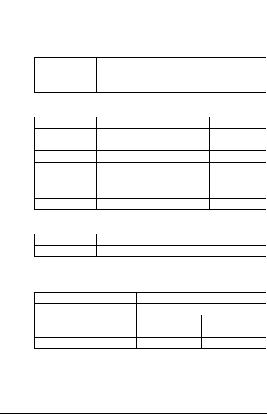
EER* <0.1%
Enrollment time <1 sec
Verification time <1 sec
*EER is dependent on specific database
4.1.2. Fingerprint Sensor Specifications
Model BioEntry OP BioEntry TC BioEntry FC
Device Name Suprema
Optical sensor I
UPEK TouchChip
TCS1CD
Atmel Fingerchip
AT77C101B-CB02
Sensor technology Optical Capacitive Thermal
Capture method Touch Touch Swipe
Sensing area 16.0mm x 19.0mm 12.8mm x 18.0mm 14.0mm x 0.4mm
Image size(pixels) 272x320 256x360 360 x 500
Image resolution 500 dpi 508 dpi 500 dpi
4.1.3. Data storage
Template capacity 9,000 at 4M Flash ( 19,000 at 8M )
LOG capacity 12,800 event
4.2. General Specifications
4.2.1. Operating range
Parameter Symbol Rate Units
Supply voltage VIN 12 V
Operating temperature (TC,OP) TOP 0 70 °C
Operating temperature (FC) TOP -20 70 °C
Humidity (non-condensing) 85 %

BioEntry Smart/Pass BioEntry Installation Guide 21
Copyright © 2005 by Suprema Inc. http://www.supremainc.com
Parameter Symbol Min Typ. Max Units
Supply current IDD 200 500 mA
Wiegand Input Port Symbol Min Typ. Max Units
High level input voltage VWIH 3.3 12 V
Low level input voltage VWIL -0.3 2.0 V
Wiegand Output Port Symbol Min Typ. Max Units
High level output voltage VOH 5.0 V
Low level output voltage VOL 0.0 V
Current source/drain IO -1/20 mA
4.3. Smart card specifications
Parameter Value
Antenna type PCB loop antenna (60mm x 57mm)
Connection with transceiver Permanent
Manufacturer / Model Dual I, DE-KTFMI
Operating Frequency Range 13.553 ~ 13.567MHz
Duty cycle 100%
4.4. Material information
Component Material / Model Manufacturer
PCB FR-4, Doosan Electronics
Enclosure ABS, HF-380 LG Chem, Ltd.
Battery CR2032 Hitachi Maxell, Ltd.
4.5. RTC battery specification
Parameter Value
Model CR2032
Manufacturer Hitachi Maxell, Ltd.
Nominal Voltage 3 V
Nominal Capacity 210mAh
UL Recognition MH12568(N)
Temp. range -20 ~ +85°C

BioEntry Smart/Pass BioEntry Installation Guide 22
Copyright © 2005 by Suprema Inc. http://www.supremainc.com
Contact Information
Suprema Inc.
DongCheon Bldg. 13-21 Yangjae-dong Seocho-gu Seoul 137-130 Korea
Tel: +82-2-571-9202
Fax: +82-2-571-9306
Website: http://www.supremainc.com
Sales inquires : sales@supremainc.com
Technical inquires : support@supremainc.com