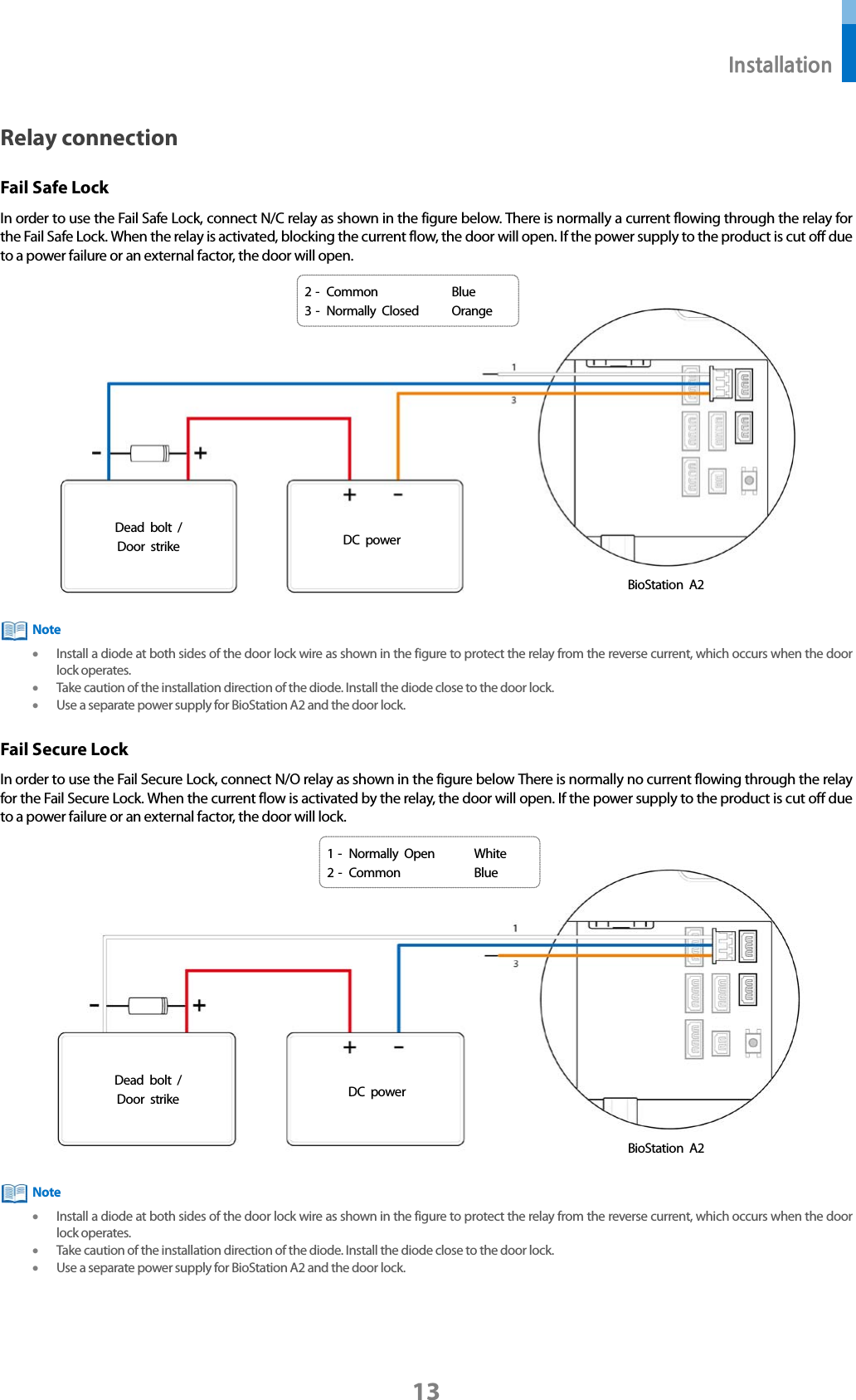
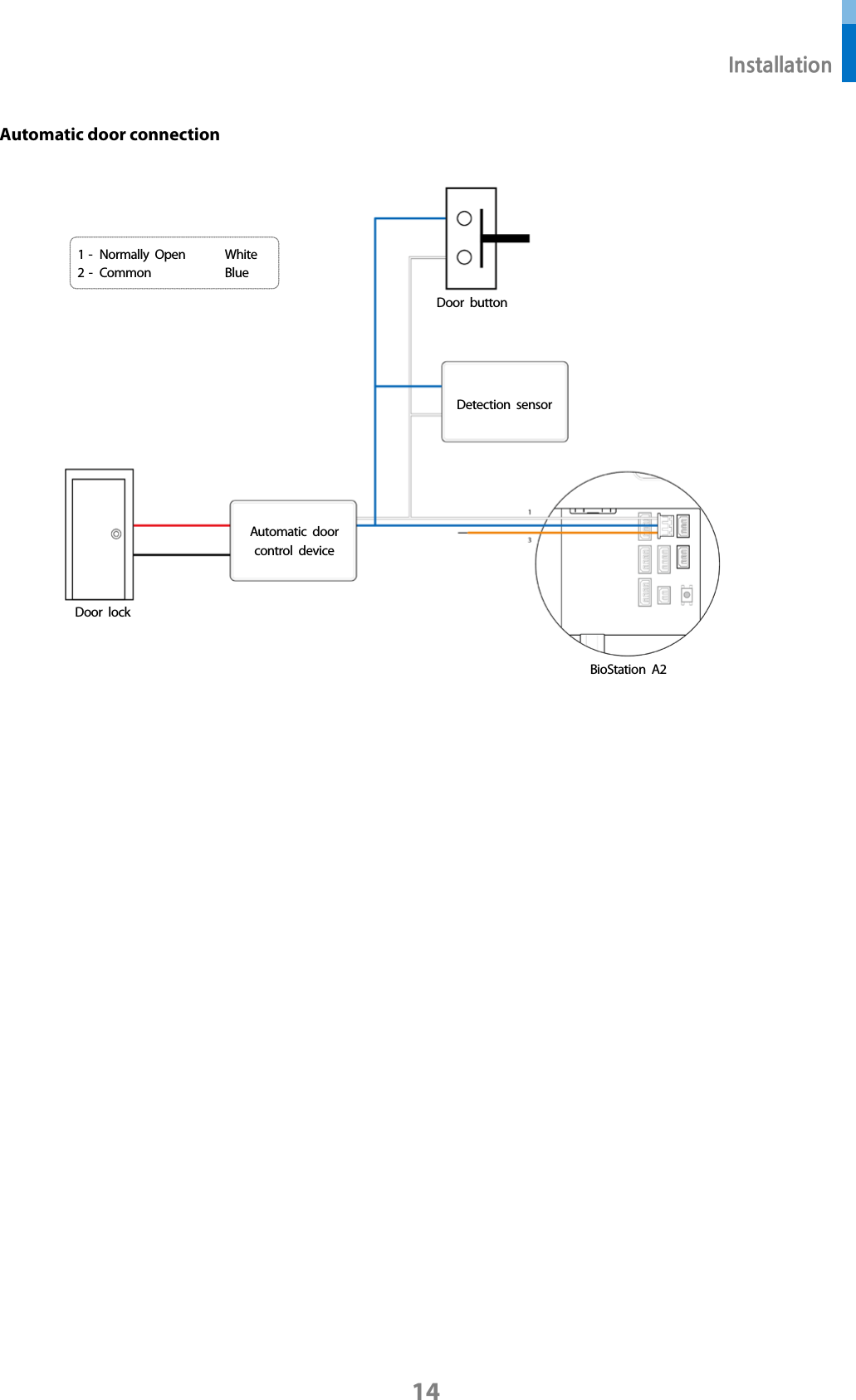
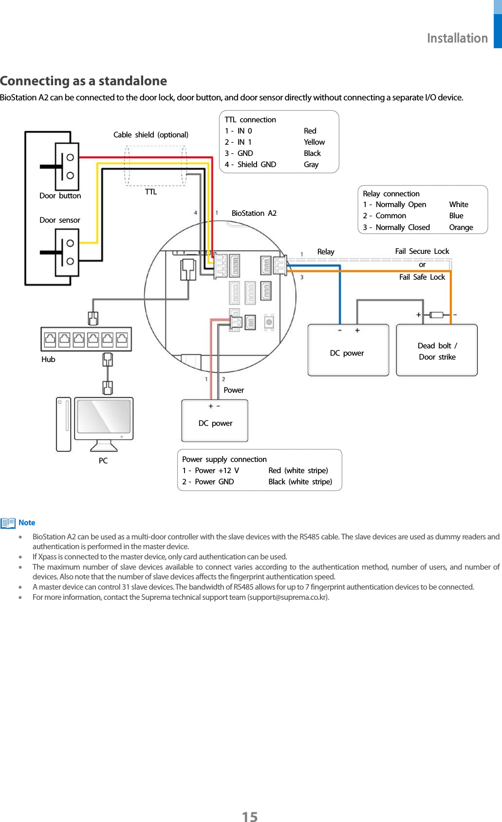
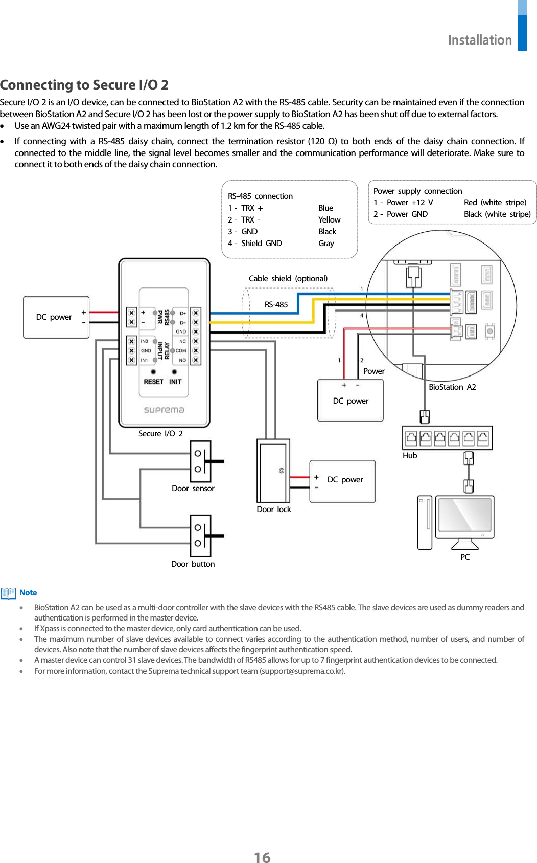
Suprema BSA2-OEPW Biostation A2 User Manual

Suprema Inc. Biostation A2

User Manual

EnglishVersion 1.00BioStation A2INSTALLATION GUIDEwww.supremainc.comEN 101.00.BSA2 V1.00A
Contents     Safety instructions ............................................................................................ 3 Introduction ...................................................................................................... 5 Components ................................................................................................................................................... 5 Name and function of each part ............................................................................................................... 6 Cables and connectors ...................................................................................................................................................... 8 How to enroll a fingerprint ........................................................................................................................ 9 Selecting a finger for fingerprint input ........................................................................................................................ 9 Fingerprint enroll method ................................................................................................................................................ 9 Installation ..................................................................................................... 10 Fixing the bracket and the product ........................................................................................................ 10 Power supply connection ........................................................................................................................... 11 Network connection .................................................................................................................................... 11 TCP/IP ..................................................................................................................................................................................11 TTL input and output connection ............................................................................................................ 12 TTL input connection .......................................................................................................................................................12 Relay connection ......................................................................................................................................... 13 Fail Safe Lock ....................................................................................................................................................................13 Fail Secure Lock ................................................................................................................................................................13 Automatic door connection ............................................................................................................................................14 Connecting as a standalone ...................................................................................................................... 15 Connecting to Secure I/O 2 ...................................................................................................................... 16 Wiegand connection ................................................................................................................................... 17 Product specifications .................................................................................. 18 Dimensions ................................................................................................................................................... 19 FCC compliance information ...................................................................... 20 EU Declaration of Conformity (CE) ........................................................... 20 Appendix ........................................................................................................ 21 Escape clause ............................................................................................................................................... 21 Copyright notice .......................................................................................................................................... 21
 Safety instructions 3 Safety instructions Observe the following instructions to use the product safely and prevent any risk of injury or property damage.  Warning Noncompliance of instructions could lead to serious injury or death. Installation Do not install the product in a place with direct sunlight, moisture, dust, or soot. • A fire or electric shock may occur. Do not install the product in a place with heat from an electric heater. • A fire or electric shock may occur due to overheating. Install the product in a dry place. • Otherwise, a product damage or electric shock may occur due to moisture. Install the product in a place with no electromagnetic interference. • Otherwise, a product damage or electric shock may occur. The user should not install or repair the product independently. • A fire, electric shock, or personal injury may occur.   • If the product has been damaged due to independent installation or repair of the product by the user, free A/S service will not be provided. Operation Do not allow liquids such as water, beverages, or chemicals get into the product.   • A fire, electric shock, or product damage may occur.   Caution Noncompliance of instructions could lead to minor injury or product damage.   Installation Do not install the power supply cable in a place where people pass by. • Product damage or physical injury may occur.   Do not install the product near a highly magnetic object such as a magnet, TV, (especially CRT) monitor, or speaker. • A product failure may occur. Use only a power supply adaptor of D.C 12 V and 500 mA or higher. • If the proper power is not used, the product may not operate normally. If installing the product outside where the product is completely exposed, it is recommended to install the product together with the enclosure. Use a separate power supply for Secure I/O 2, electric lock and BioStation A2 respectively. • If connecting and using the power supply to these devices together, the devices may malfunction.
 Safety instructions 4 Operation Do not drop the product or apply an impact to the product. • A product failure may occur. Manage the password with care not to disclose it to others and change the password periodically.   • Otherwise, illegal intrusion may occur.   Do not press the buttons on the product forcibly or using a sharp tool.   • A product failure may occur. Be careful not to contaminate or damage the fingerprint contact unit with a dirty hand or foreign substances.   • Deterioration in fingerprint authentication performance and a product failure may occur.   When cleaning the product, wipe the product with a soft and dry cloth and no water, benzene or alcohol.   • Otherwise, a product failure may occur.   BioStation A2 uses capacitive buttons. If the environment is moist from wet weather or the product surface is smeared with a lot of water, wipe off the product with a dry towel before using it.  RTC battery Replacing the battery with an incorrect type of battery may cause explosion. Discard the battery according to the appropriate regional or international waste regulations.
 Introduction 5 Introduction Components   Components may vary according to the installation environment.      Note BioStation A2 Wall bracket Fixing screw (4 EA) PVC anchor (4 EA) Diode (1 EA) Connection cable (2 pins 1 EA, 3 pins 2 EA, 4 pins 4 EA) Ferrite core (1 EA) Drilling template Quick guide 120 Ω resistor (1 EA)
 Introduction 6 Name and function of each part     Name Description Microphone Delivers the voice of the user when the interphone is connected.   LCD screen Provides UI for operation. Menu button (    )  Displays the list of menus. Home button (    )  Navigates to the home screen. Cancel button (    )  Navigates back to the previous screen. Speaker Delivers sound. LED lamp Indicates the operational status of the product with the color of the LED lamp. Fingerprint authentication unit Part to scan the fingerprint for entrance. RF card authentication unit Part to scan the card for entrance. USB memory slot Connects USB memory. Mini USB cable slot Will be supported in the future. TTL input (4 pins) Connect the TTL input and output cable. Fingerprint authentication unit Menu button LED lamp Microphone LCD screen USB memory slot TTL input (4 pins) Power supply (2 pins) Relay 0 (3 pins) RF card authentication unit Mini USB cable slot Speaker Camera Home button Cancel button Ethernet Relay 1 (3 pins) Wiegand input (4 pins) Wiegand output (4 pins) RS-485 (4 pins) Booting mode button
 Introduction 7 RS-485 (4 pins) Connect the RS-485 cable. TTL output (4 pins) Connect the TTL input and output cable. Relay 0, 1 (3 pins) Connect the relay cable. Power supply (2 pins) Connect the power supply cable. Ethernet Connect the Ethernet cable. Wiegand input (4 pins) Connect the Wiegand input and output cable. Wiegand output (4 pins) Connect the Wiegand input and output cable.
 Introduction 8 Cables and connectors Power supply  Pin Name Color 1 Power +12 V   Red (white stripe) 2 Power GND Black (white stripe) Relay  Pin Name Color 1 Normally Open White 2 Common Blue 3 Normally Closed Orange RS-485  Pin Name Color 1 TRX + Blue 2 TRX - Yellow 3 GND Black 4 Shield GND Gray TTL input  Pin Name Color 1 IN 0 Red 2 IN 1 Yellow 3 GND Black 4 Shield GND Gray Wiegand input and output  Pin Name Color 1 IN 0 / OUT 0 Green 2 IN 1 / OUT 1 White 3 GND Black 4  Shield GND Gray
 Introduction 9 How to enroll a fingerprint In order to improve the fingerprint authentication rate, register the fingerprint correctly. BioStation A2 can recognize a fingerprint even if the angle and position of a user's fingerprint input change. If you register the fingerprint with attention to the following matters, the authentication rate can be improved. Selecting a finger for fingerprint input • In preparation for the case that the fingerprint of a specific finger cannot be used, for example if the user is lifting a load with one hand or a finger gets hurt, up to 10 fingerprints for each user can be registered.   • In the case of a user whose fingerprint cannot be recognized well, the authentication rate can be improved by enrolling the same finger twice repeatedly.   • If a finger has a cut or the fingerprint is blurry, select another finger for the fingerprint. • It is recommended to use the index finger or the middle finger when scanning the fingerprint. The authentication rate can be reduced if it is difficult to place another finger at the center of fingerprint sensor accurately.  Fingerprint enroll method 1 When a message saying “Scan the fingerprint.” is displayed on the LCD screen for enrolling the fingerprint, place the finger with the fingerprint to be registered on the fingerprint authentication unit and press the finger gently for better authentication.    2 When the re-input screen is displayed after a beep sound, scan the fingerprint of the registered finger again (scan the fingerprint of a finger to be registered twice).  Cautions for enrolling a fingerprint When a fingerprint is recognized, it is compared with the initially registered fingerprint, so the initial fingerprint enroll  is the most important. Pay attention to the following matters when enrolling the fingerprint. • Place the finger deep enough to contact with the sensor completely. • Place the center of the fingerprint in the center of the sensor.   • If a finger has a cut or the fingerprint is blurry, select another finger for the fingerprint.   • Scan the fingerprint correctly without moving according to the instruction on the screen.   • If you make the finger upright so that the contact area with the sensor has decreased or the angle of finger has warped, fingerprint authentication may not be performed.    When the fingerprint recognition fails BioStation A2 can recognize a fingerprint regardless of a change of season or finger condition. However, the authentication rate may vary according to the external environment or fingerprint input method.   If the fingerprint authentication cannot be done smoothly, it is recommended to take the following measures.   • If the finger is smeared with water or sweat, dry off the finger and then scan the finger. • If the finger is too dry, blow your breath on the fingertips and then scan the finger. • If the finger has a cut, register the fingerprint of another finger. • The initially registered fingerprint often may have not been scanned correctly, so register the fingerprint again according to ‘Cautions for enrolling a fingerprint’.       Note
 Installation 10 Installation Fixing the bracket and the product 1 Determine the correct position to install the bracket using the provided drilling template. Fix the bracket firmly using fixing screws through the bracket to the position where BioStation A2 will be installed.   If installing BioStation A2 on a concrete wall, drill holes, insert PVC anchors, and fix them with fixing screws.  2 Assemble the cable cover and install BioStation A2 onto the fixed bracket.   3 Connect BioStation A2 to the bracket by rotating the product fixing screw of BioStation A2.   Note
 Installation 11 Power supply connection   • Use a power supply adaptor of DC 12 V (± 10%) with a minimum of 1,500 mA which has obtained the approval of IEC/EN 60950-1. If you wish to connect and use another device to the power supply adaptor, you should use an adaptor with a current capacity which is the same or larger than the total power consumption required for the terminal and another device.     • Use a separate power supply for Secure I/O 2, the electric lock, and the product respectively. If connecting and using the power supply to these devices together, the devices may malfunction.   Network connection TCP/IP LAN connection (connecting to a hub) You can connect the product to a hub using a general type CAT-5 cable.     Hub BioStation A2 PC Note 1 -  Power +12 V Red (white stripe) 2 -  Power GND Red (white stripe) UPS (Optional) DC power BioStation A2
 Installation 12 LAN connection (connecting to a PC directly) BioStation A2 has an automatic MDI/MDIX function so that it can be connected to a PC directly using a normal straight type CAT-5 cable, not a cross cable.   TTL input and output connection   TTL input connection    Door sensor BioStation A2 1 -  IN 0 Red 2 -  IN 1 Yellow 3 -  GND Black 4 -  Shield GND  Gray   Door button Cable shield (optional) BioStation A2 PC
 Installation 13 Relay connection Fail Safe Lock In order to use the Fail Safe Lock, connect N/C relay as shown in the figure below. There is normally a current flowing through the relay for the Fail Safe Lock. When the relay is activated, blocking the current flow, the door will open. If the power supply to the product is cut off due to a power failure or an external factor, the door will open.   • Install a diode at both sides of the door lock wire as shown in the figure to protect the relay from the reverse current, which occurs when the door lock operates. • Take caution of the installation direction of the diode. Install the diode close to the door lock. • Use a separate power supply for BioStation A2 and the door lock. Fail Secure Lock In order to use the Fail Secure Lock, connect N/O relay as shown in the figure below There is normally no current flowing through the relay for the Fail Secure Lock. When the current flow is activated by the relay, the door will open. If the power supply to the product is cut off due to a power failure or an external factor, the door will lock.   • Install a diode at both sides of the door lock wire as shown in the figure to protect the relay from the reverse current, which occurs when the door lock operates. • Take caution of the installation direction of the diode. Install the diode close to the door lock. • Use a separate power supply for BioStation A2 and the door lock.  Note BioStation A2 1 -  Normally Open White 2 -  Common Blue Dead bolt / Door strike DC power Note BioStation A2 Dead bolt / Door strike DC power 2 -  Common Blue 3 -  Normally Closed Orange
 Installation 14 Automatic door connection     BioStation A2 Automatic door control device Detection sensor 1 -  Normally Open White 2 -  Common Blue Door button Door lock
 Installation 15 Connecting as a standalone BioStation A2 can be connected to the door lock, door button, and door sensor directly without connecting a separate I/O device.      • BioStation A2 can be used as a multi-door controller with the slave devices with the RS485 cable. The slave devices are used as dummy readers and authentication is performed in the master device. • If Xpass is connected to the master device, only card authentication can be used. • The maximum number of slave devices available to connect varies according to the authentication method, number of users, and number of devices. Also note that the number of slave devices affects the fingerprint authentication speed. • A master device can control 31 slave devices. The bandwidth of RS485 allows for up to 7 fingerprint authentication devices to be connected. • For more information, contact the Suprema technical support team (support@suprema.co.kr).      Note BioStation A2 PC Door button Door sensor or Cable shield (optional) TTL TTL connection 1 -  IN 0 Red 2 -  IN 1 Yellow 3 -  GND Black 4 -  Shield GND  Gray Relay connection 1 -  Normally Open White 2 -  Common Blue 3 -  Normally Closed Orange Hub Fail Secure Lock  Fail Safe Lock DC power DC power Dead bolt / Door strike Power supply connection 1 -  Power +12 V Red (white stripe) 2 -  Power GND Black (white stripe) Relay Power
 Installation 16 Connecting to Secure I/O 2 Secure I/O 2 is an I/O device, can be connected to BioStation A2 with the RS-485 cable. Security can be maintained even if the connection between BioStation A2 and Secure I/O 2 has been lost or the power supply to BioStation A2 has been shut off due to external factors. • Use an AWG24 twisted pair with a maximum length of 1.2 km for the RS-485 cable. • If connecting with a RS-485 daisy chain, connect the termination resistor (120 Ω) to both ends of the daisy chain connection. If connected to the middle line, the signal level becomes smaller and the communication performance will deteriorate. Make sure to connect it to both ends of the daisy chain connection.     • BioStation A2 can be used as a multi-door controller with the slave devices with the RS485 cable. The slave devices are used as dummy readers and authentication is performed in the master device. • If Xpass is connected to the master device, only card authentication can be used. • The maximum number of slave devices available to connect varies according to the authentication method, number of users, and number of devices. Also note that the number of slave devices affects the fingerprint authentication speed. • A master device can control 31 slave devices. The bandwidth of RS485 allows for up to 7 fingerprint authentication devices to be connected. • For more information, contact the Suprema technical support team (support@suprema.co.kr).      Note BioStation A2 PC Door lock Secure I/O 2 Door button Door sensor RS-485 connection 1 -  TRX + Blue 2 -  TRX  -  Yellow 3 -  GND Black 4 -  Shield GND Gray Cable shield (optional) DC power DC power DC power Hub RS-485 Power Power supply connection 1 -  Power +12 V Red (white stripe) 2 -  Power GND Black (white stripe)
 Installation 17 Wiegand connection      Controller 1 -  IN 0 Green 2 -  IN 1 White 3 -  GND Black 4 -  Shield GND Gray RFID reader BioStation A2 Use  as a Wiegand input device Use as a Wiegand output device Cable shield (optional) Cable shield (optional) BioStation A2 1 -  OUT 0 Green 2 -  OUT 1 White 3 -  GND Black 4 -  Shield GND Gray
Product specifications 18 Product specifications Category Feature Specification General Biometric Fingerprint LFD Supported RF Option 2.4 GHz, 125 kHz Mifare/DesFire/DesFire EV1/Felica/NFC, 125 kHz iClass SE Storage capacity Max. User (1:1) 500,000 Max. User (1:N) 100,000 Max. Template (1:1) 1,000,000 Max. Template (1:N) 200,000 Max. Text Log 5,000,000 Max. Image Log 50,000 Interface Wi-Fi Supported TCP/IP Supported RS-485 1ch Host or Slave (Selectable) RS-232 Supported Wiegand 1ch Input, 1ch Output TTL input 1ch Input Relay 2 Relay USB USB 2.0 (Host) Relay Voltage Max. 24 V DC Current 0.5 A, Max. 1.A Hardware CPU 1.0 GHz Memory 8 GB Flash + 1 GB RAM LCD 5” color touch LCD LED Multiple colors Sound 24 bit/Voice DSP (echo cancel) Operating temperature -20°C ~ 50°C Temper Supported Power 9 V ~ 18 V PoE Supported Dimension (W x H x D mm) 155 x 155 x 40 Certificates CE, FCC, KC, RoHS, REACH, WEEE
 Product specifications 19 Dimensions (Unit: mm)
 FCC compliance information 20 FCC compliance information THIS DEVICE COMPLIES WITH PART 15 OF THE FCC RULES.   Operation is subject to the following two conditions: (1) This device may not cause harmful interference, and (2) This device must accept any interference received, including interference that may cause undesired operation.  Note: This equipment has been tested and found to comply with the limits for a Class B digital device, pursuant to part 15 of the FCC Rules. These limits are designed to provide reasonable protection against harmful interference in a residential installation. This equipment generates, uses, and can radiate radio frequency energy and, if not installed and used in accordance with the instructions, may cause harmful interference to radio communications. However, there is no guarantee that interference will not occur in a particular installation. If this equipment does cause harmful interference to radio or television reception, which can be determined by turning the equipment off and on, the user is encouraged to try to correct the interference by one or more of the following measures: • Reorient or relocate the receiving antenna. • Increase the separation between the equipment and receiver. • Connect the equipment into an outlet on a circuit different from that to which the receiver is connected. • Consult the dealer or an experienced radio/TV technician for help. Modifications not expressly approved by the manufacturer could void the user's authority to operate the equipment under FCC rules.     This appliance and its antenna must not be co-located or operation in conjunction with any other antenna or transmitter. A minimum separation distance of 20 cm must be maintained between the antenna and the person for this appliance to satisfy the RF exposure requirements.   EU Declaration of Conformity (CE)   This product is CE marked according to the provisions of the R&TTE Directive(1999/5/EC). Hereby, Suprema Inc. declares that this product is in compliance with the essential requirements and other relevant provisions of Directive 1999/5/EC. This device is Class 1 radio equipment under the European Radio and Telecommunications Terminal Equipment (R&TTE) Directive (1999/5/EC).     For more information, contact us at the following contact information. Suprema Inc. Website: https://www.supremainc.com Address: Parkview Tower F16, 248, Jeongjail-ro, Bundang-gu, Seongnam-si, Gyeonggi-do, Korea (Jeongja-dong 6) Tel: +82-31-783-4502 / Fax: +82-31-783-4503
 Appendix 21 Appendix Escape clause • The information in this manual is provided with regard to the Suprema's products.   • The right to use is acknowledged only for products included in the terms and conditions of the sales agreement guaranteed by Suprema. The right of license to other intellectual property rights not discussed in this manual is not acknowledged.   • Suprema does not guarantee or hold responsibility for the suitability and commerciality of the product for a specific purpose, or the infringement of patent, copyright, or other intellectual property rights with regard to sales or usage of Suprema's products.   • Do not use the product of Suprema under the situations related to medical, rescue of human lives, or maintenance of life, as a person may get injured or lose his/her life due to product malfunction. If an accident occurs while a consumer is using the product under the situations described as examples above, employees, subsidiaries, branches, affiliated companies and distributors of Suprema do not accept responsibility nor will they reimburse for all related direct and indirect expenses or expenditure including attorney fees even if the consumer has discovered any shortcomings in the product design or manufacturing process and claims this as a significant fault.   • Suprema may modify the product size and specifications at any time without proper notice in order to improve the safety, function and design of the product. Designers must keep in mind that functions or descriptions indicated as "to be implemented" or "undefined" may change at any time. Suprema will implement or define such functions or descriptions in the near future and Suprema accepts no responsibility for compatibility issues and any other problems arising from such compatibility issues.   • If you wish to obtain the newest specifications before ordering the product, contact Suprema through a Sales Representative or local distributor of Suprema.    Copyright notice The copyright of this document is vested in Suprema. The rights of other product names, trademarks and registered trademarks are vested in each individual or organization that owns such rights.
www.supremainc.comwww.supremainc.com

Navigation menu