User manual

Safety precautions
Product components
Optional accessories
Names of each parts
Product Dimension
Cables and Connectors
Power Connection
LAN Connection
RS485 Connection
Relay Connection
Digital Input Connection
WiegandInput/Output
Output
Installation of Wall-mount Bracket
Installation Reference
Specification
Electrical Specification
FCC Rules
Contents
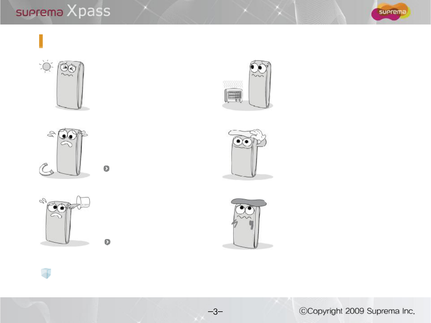
The list below is to keep user s safety and prevent any loss. Please read safety
precautions carefully before use.
Do not install the device in a
place subject to direct sun
light, humidity, dust or soot.
Do not place a magnet
near the product.
Do not place the device next
to heating equipments.
Be careful not to let liquid like
water, drinks or chemicals
leak inside the device.
Clean the device often to
remove dust on it.
In cleaning, do not splash
water on the device but wipe it
out with smooth cloth or towel.
Safety precautions
It may cause a damage or
a failure to the product.
It may cause a failure.
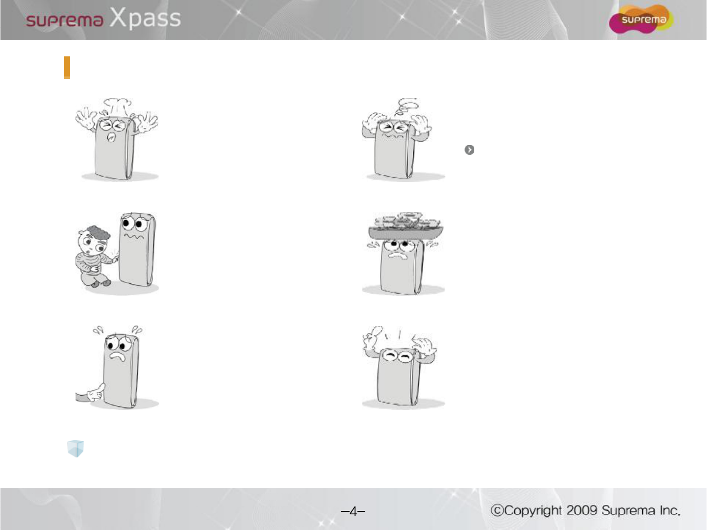
Do not drop the device.
Do not damage the device.
Do not disassemble, repair or
alter the device.
Do not let children touch the
devicewithout supervision.
Do not use the device for
any other purpose than
specified.
Contact your nearest dealer in
case of a trouble or problem.
The warranty does net apply to any
product damage cause by an
arbitrary installation or repair.
Safety precautions
The list above is to keep user s safety and prevent any loss. Please read safety
precautions carefully before use.
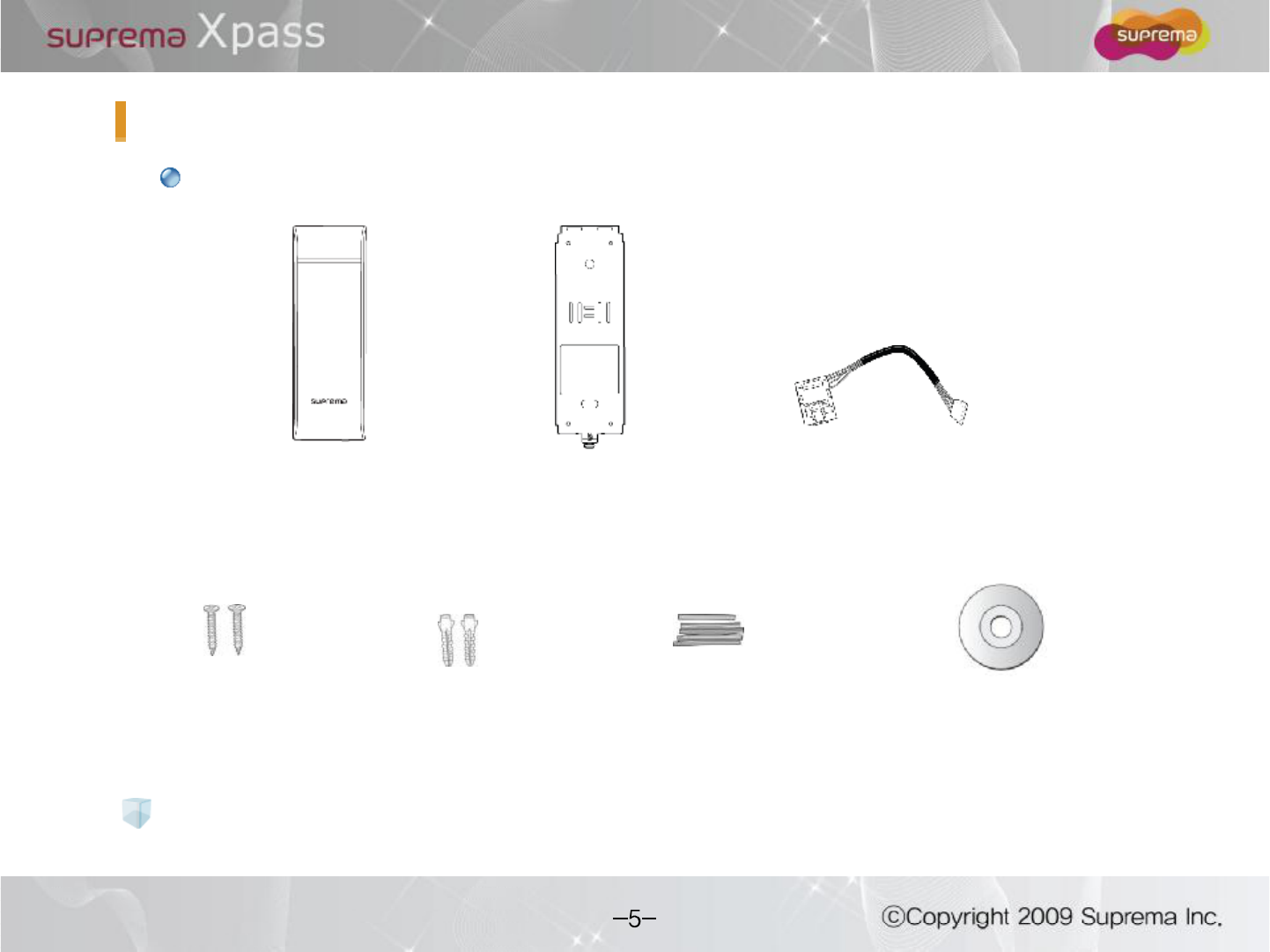
Productcomponents
Xpass bracket
Wall mounting screws
(2 ea)
Knife Blocks
(2 ea)
Shrinkable Tubes Software CD
Extended Ethernet Cable
Basic components
The components shown above may differ depending on the installation environment.
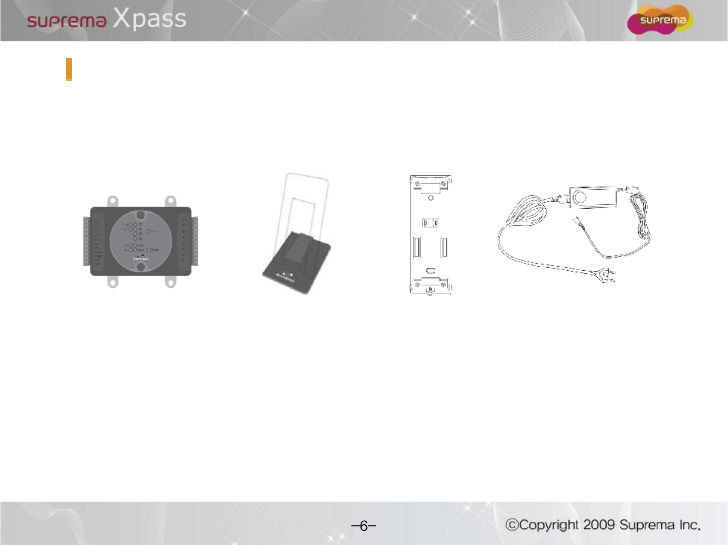
Plastic standSecure I/O
Optional accessories
Extended bracket adaptor
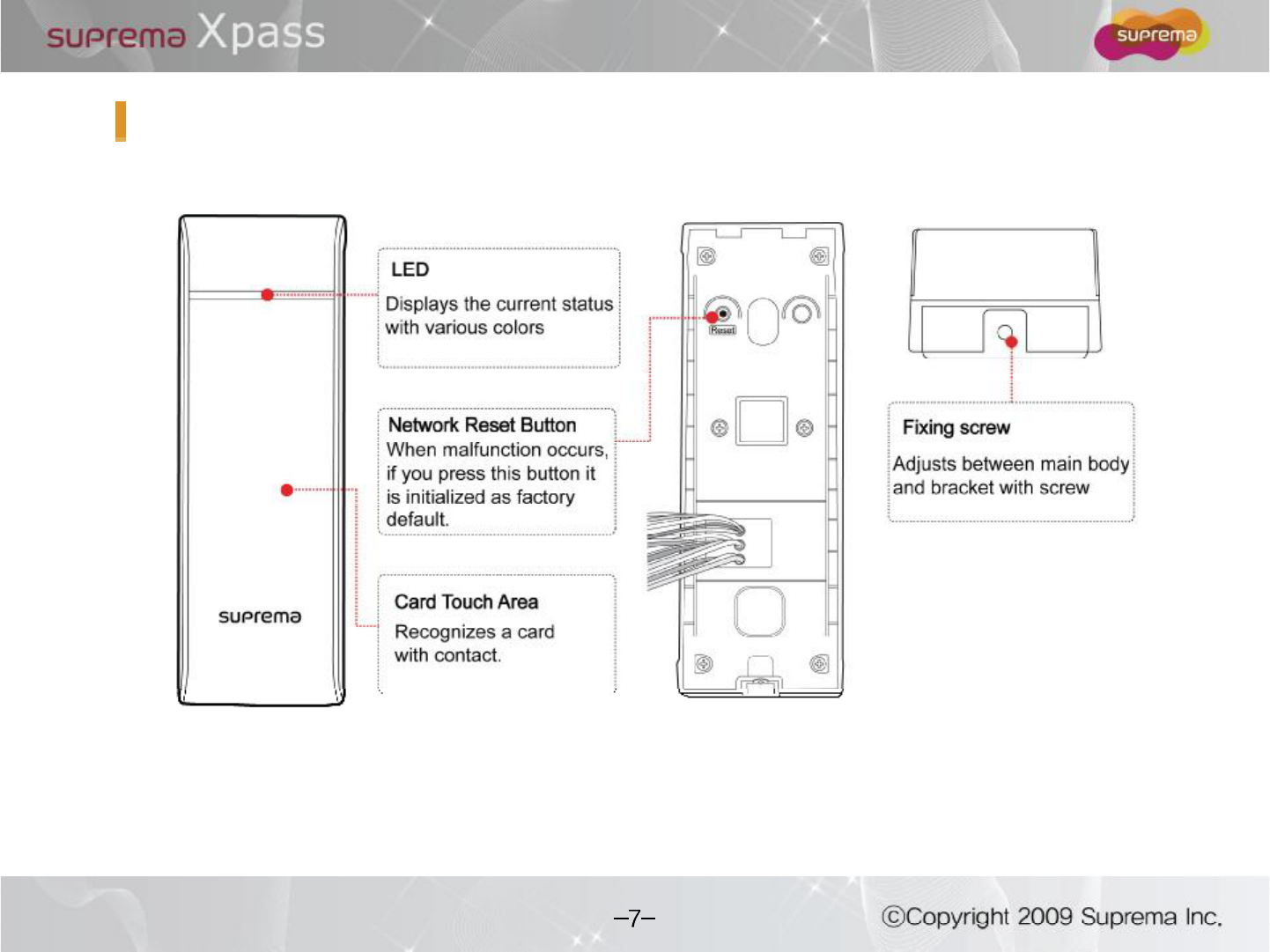
Names of each parts
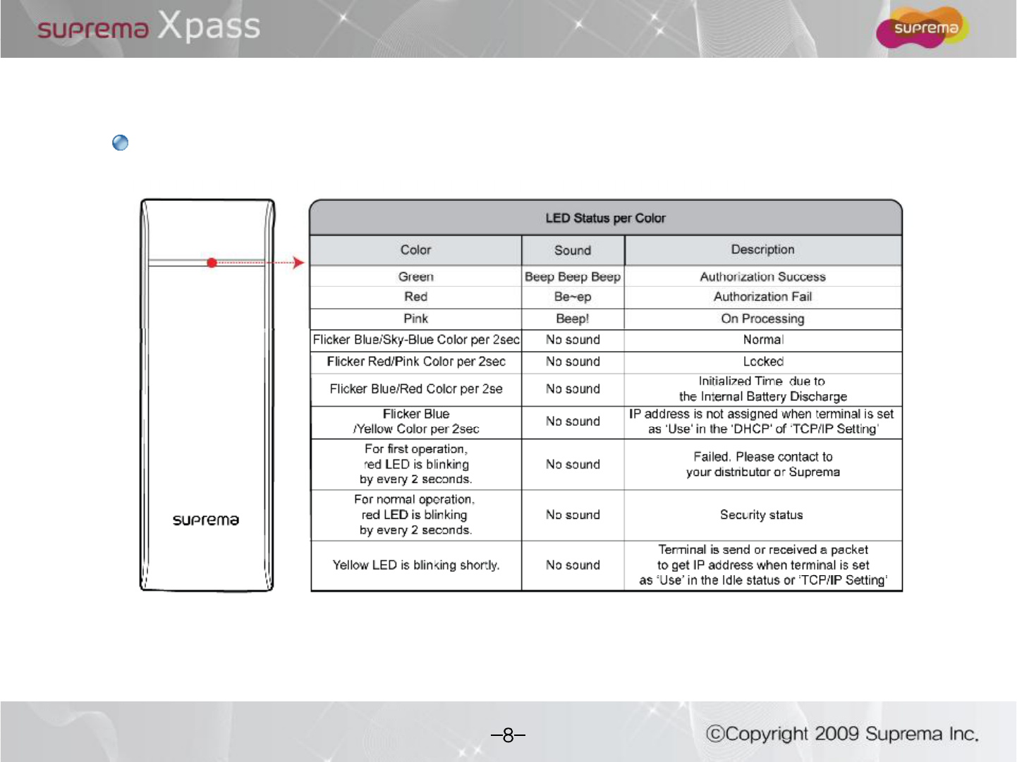
LED status
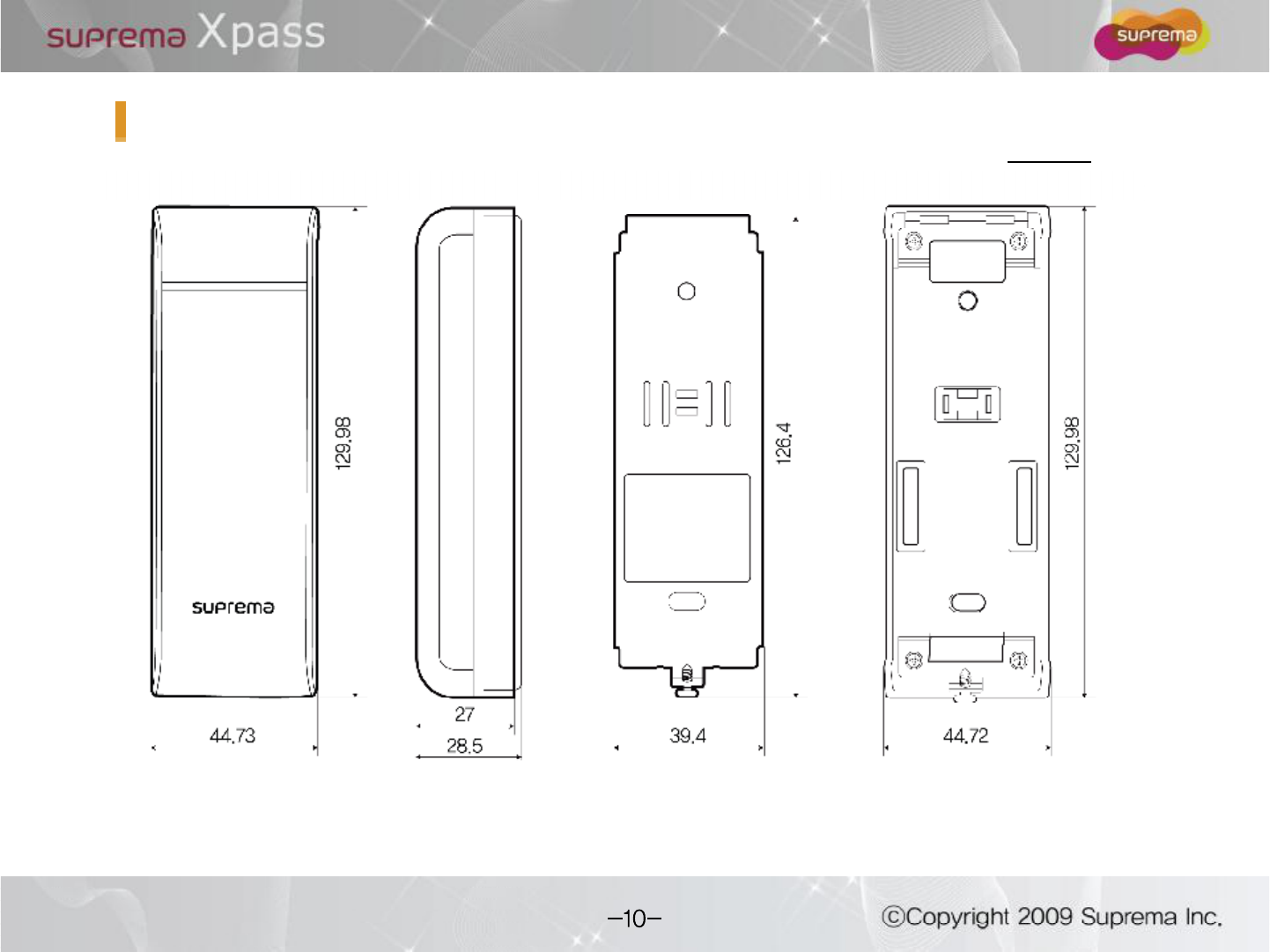
Product Dimension
< Extended bracket >< Front View > < Bracket >< Side View >
(unit : mm)
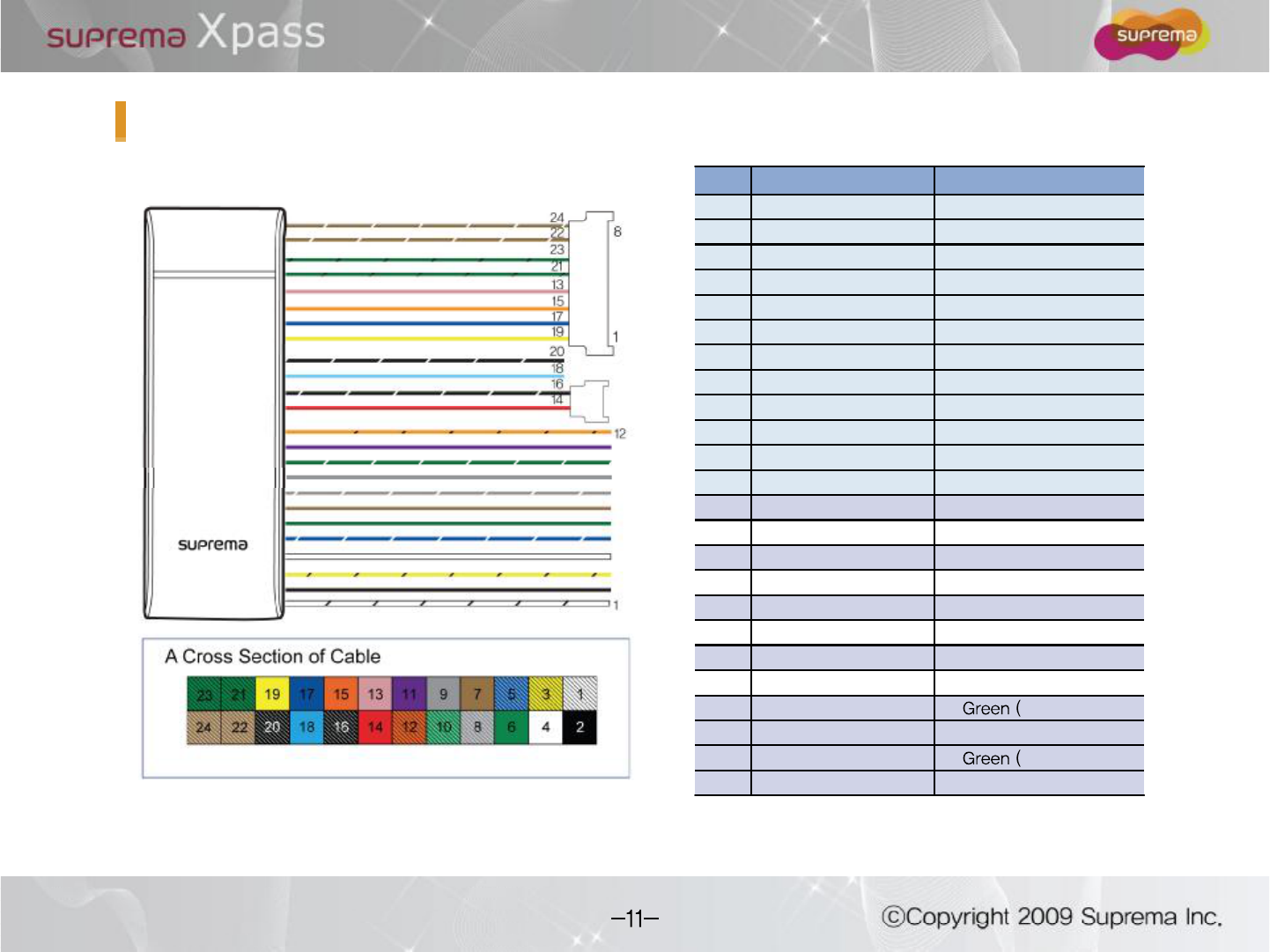
No Pin Name Color
1485 GND White (black string)
2Wiegand-GND Black
3485 - Yellow (black string)
4Wiegand-1 White
5485 + Blue (white string)
6Wiegand-0 Green
7Input-1 Brown
8 Relay Open Gray (white string)
9Input-GND Gray
10 Relay Com Green (white string)
11 Input-0 Purple
12 Relay Close Orange (black string)
13 TX+ (LAN) Pink
14 Power IN+ Red
15 TX-(LAN) Orange
16 Power IN- Black (white string)
17 RX+ (LAN) Blue
18 Power OUT+ Light Blue
19 RX-(LAN) Yellow
20 Power OUT- Black (white string)
21 VB1 black string)
22 VB2 Brown (white string)
23 VB1 black string)
24 VB2 Brown (white string)
Cables and Connectors
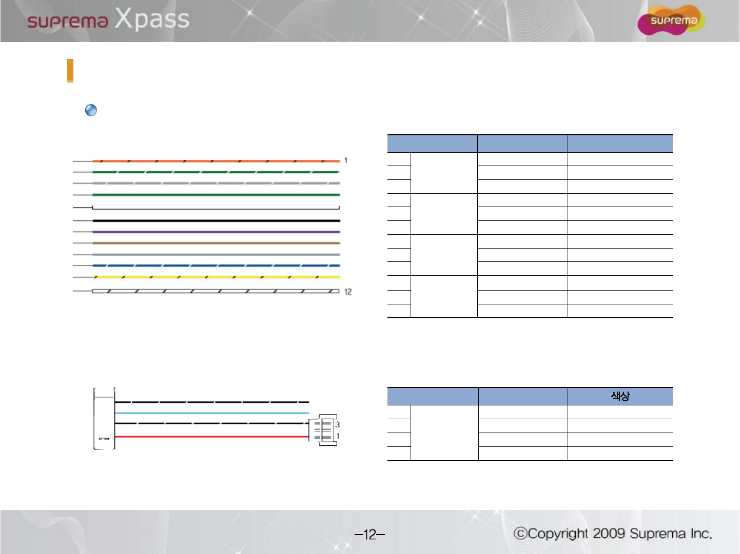
Pin Pin Name Color
1
Relay
RLY NC Orange (black string)
2RLY COM Green (white string)
3RLY NO Gray (white string)
4
Wiegand
WGD D0 Green
5WGD D1 White
6WGD GND Black
7
Switch
IN 0 Purple
8IN 1 Brown
9IN GND Gray
10
485
485+ Blue (white string)
11 485- Yellow (black string)
12 485 GND White (black string)
Cables and Connectors
Pin Pin Name
Power
POWER OUT - Black (white string)
POWER OUT + Light Blue
3POWER IN - Black (white string)
1POWER IN + Red
Cable Specification
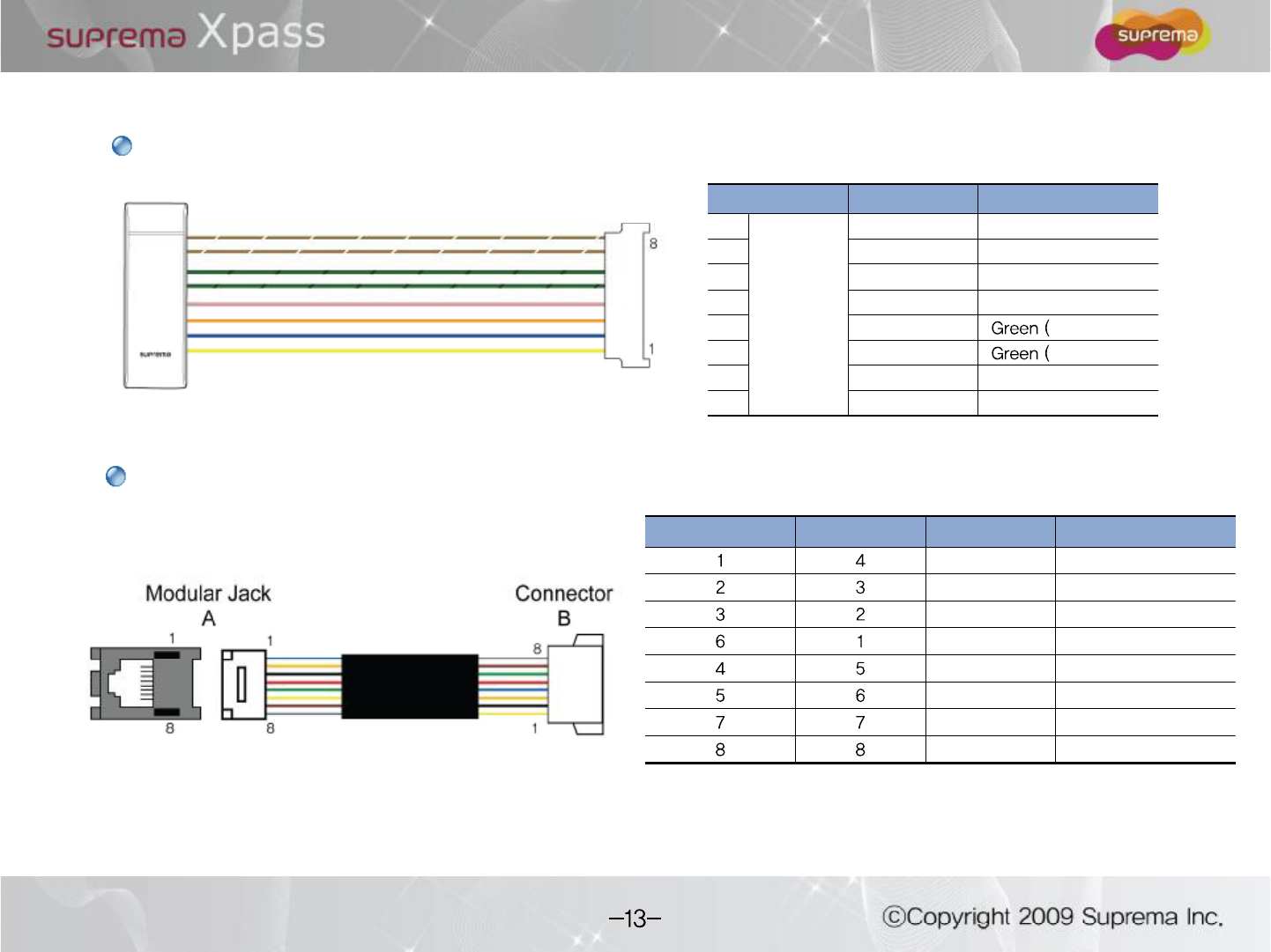
Ethernet extension cable
Pin Pin Name Color
1
LAN
RX- Yellow
2 RX+ Blue
3TX- Orange
4TX+ Pink
5VB1 black string)
6VB1 black string)
7VB2 Brown (white string)
8VB2 Brown (white string)
LAN cable
Modular Jack (A) Connector (B) Pin Name Color
TX+ Blue
TX- Orange
RX+ Black
RX- Yellow
VB1 Red
VB1 Green
VB2 Brown
VB2 Gray
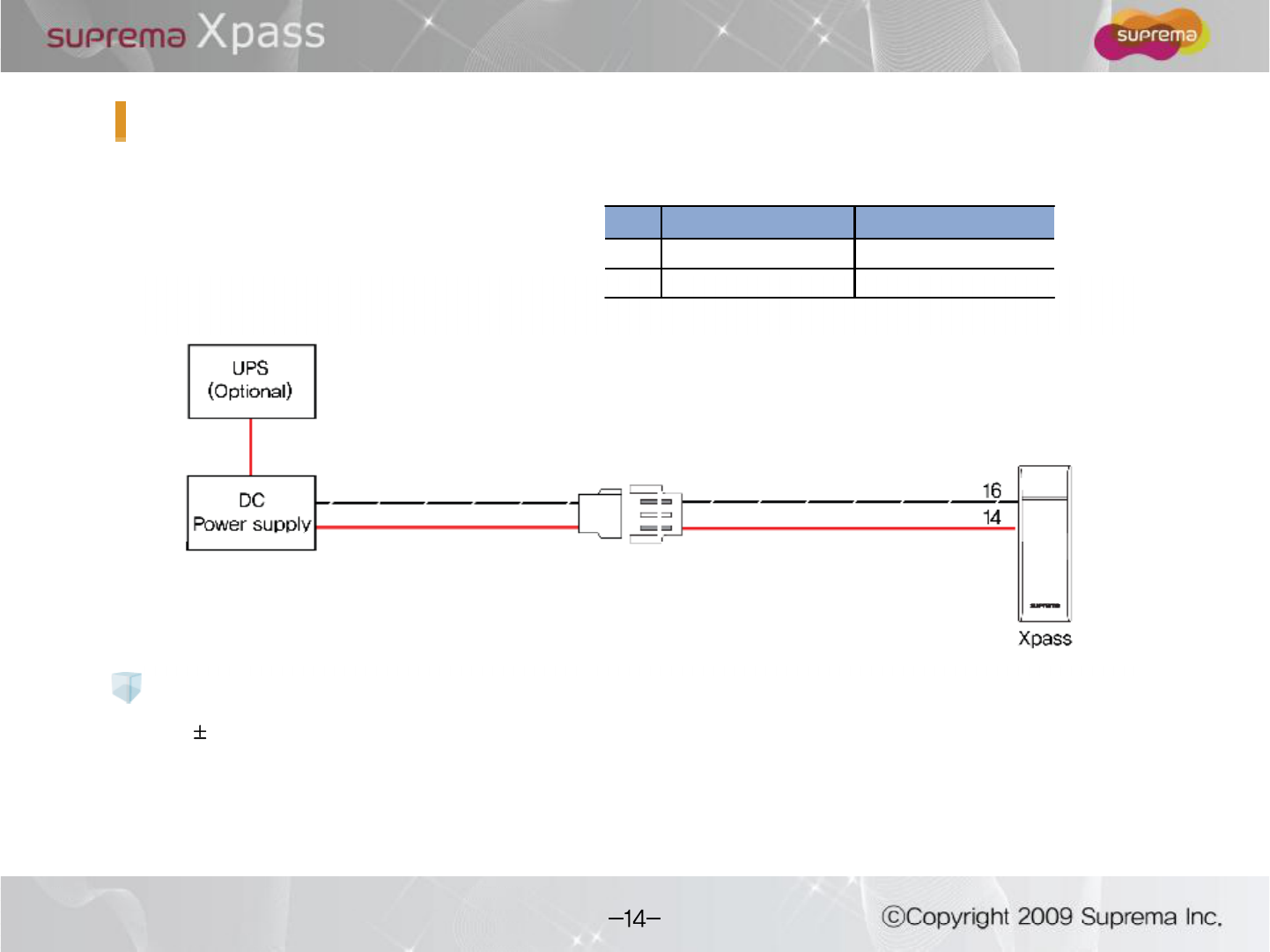
Power Connection1
12V 10%, at least 500mA.
Comply with standard IEC/EN 60950-1.
To share the power with other devices, use a power supply with higher current ratings.
Recommended power supply
Pin Pin Name Color
14 POWER IN+ Red
16 POWER IN- Black (white string)
Power Connection2
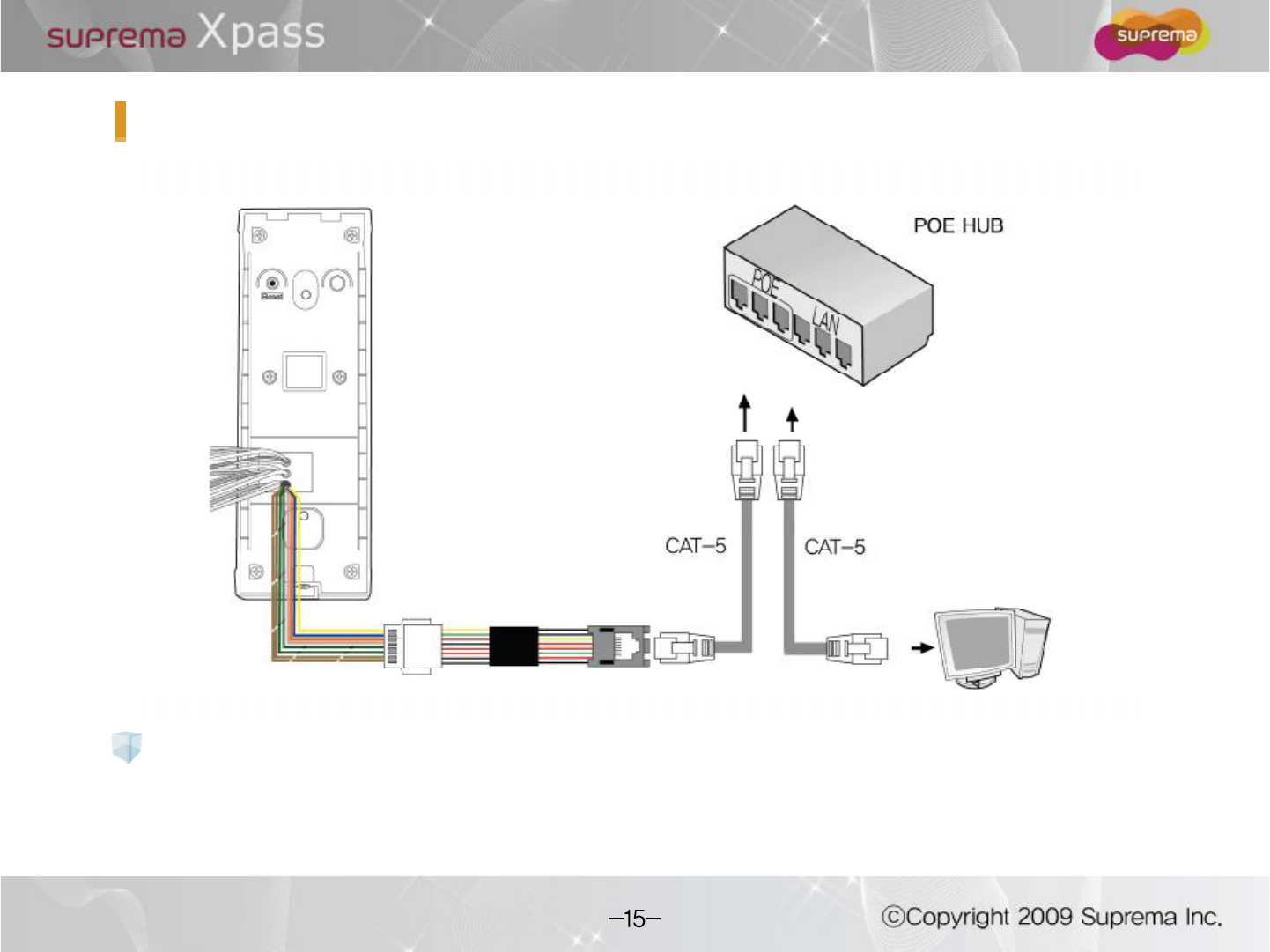
Please use the distance of LAN cable within 100m in case of POE power.
Recommended power supply
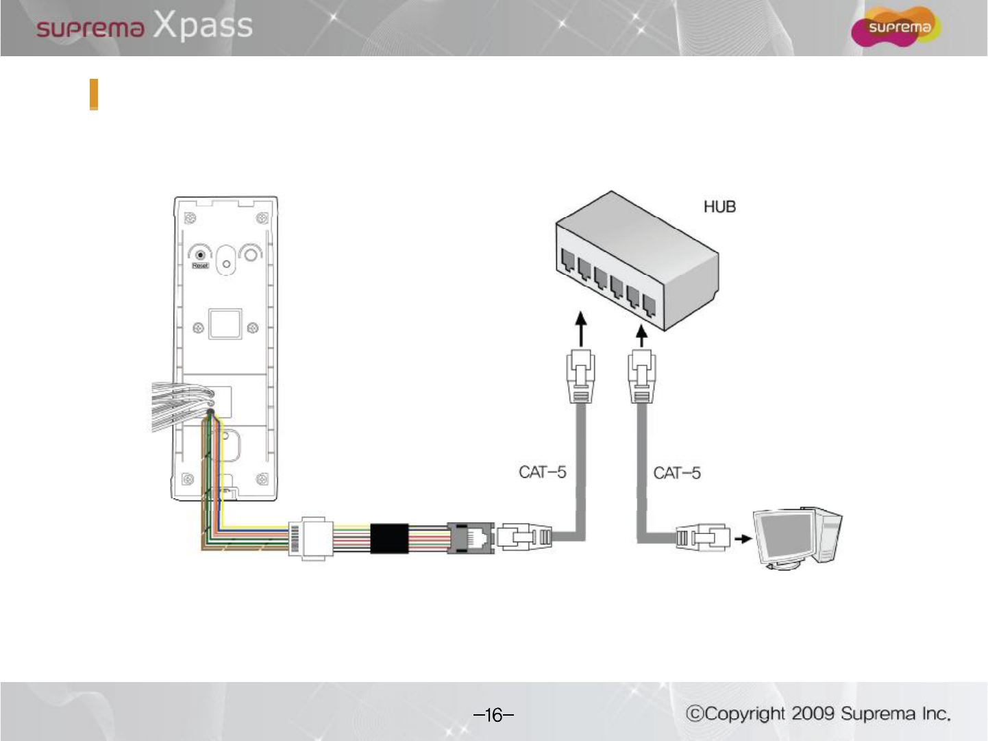
LAN Connection
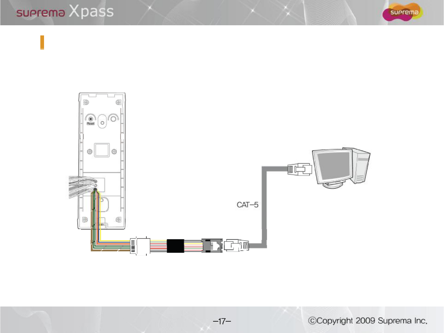
LAN Connection (Direct connection with PC)
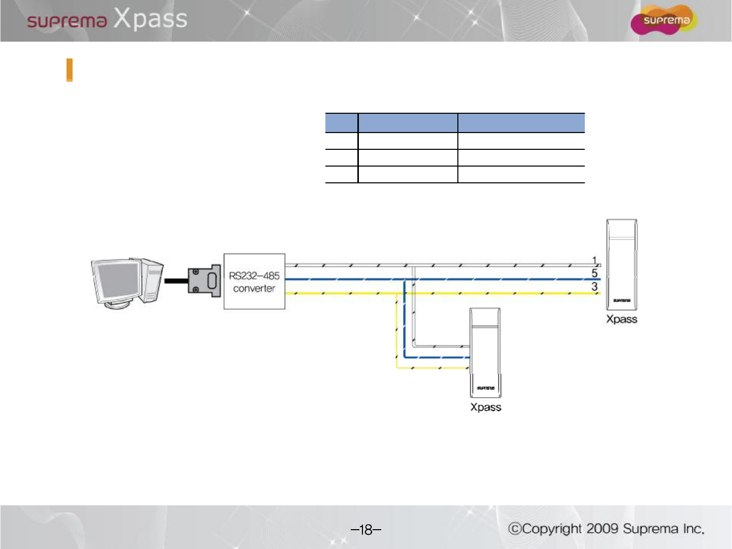
RS485 Connection for Host Communication
Pin Pin Name Color
1485 GND White (black string)
3485 - Yellow (black string)
5 485 + Blue (white string)
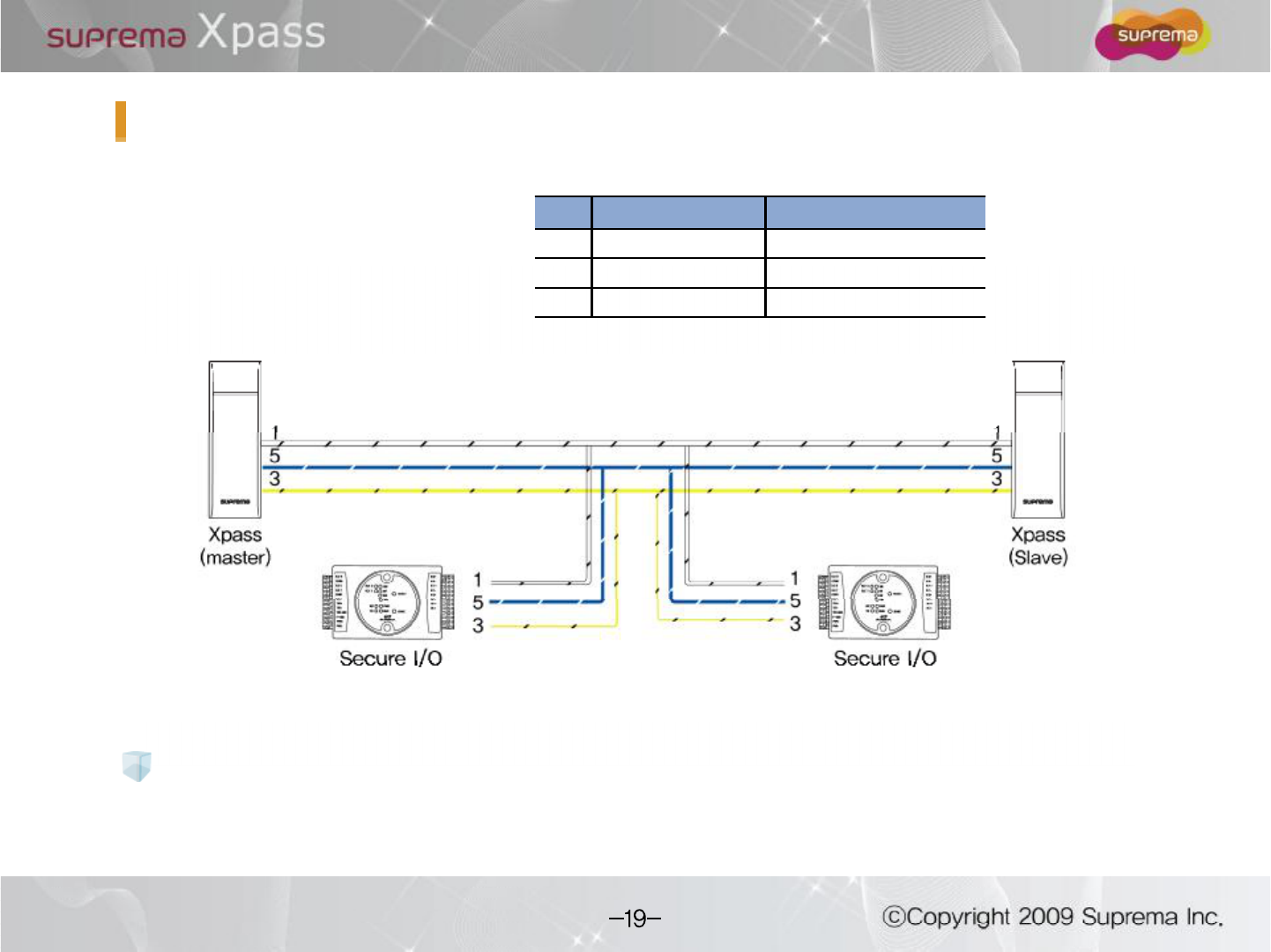
RS485 Connection for Secure I/O
Max number of devices
Pin Pin Name Color
1485 GND White (black string)
3485 - Yellow (black string)
5 485 + Blue (white string)
Maximum eight(8) devices (including Master) interworksin an RS485 loop.
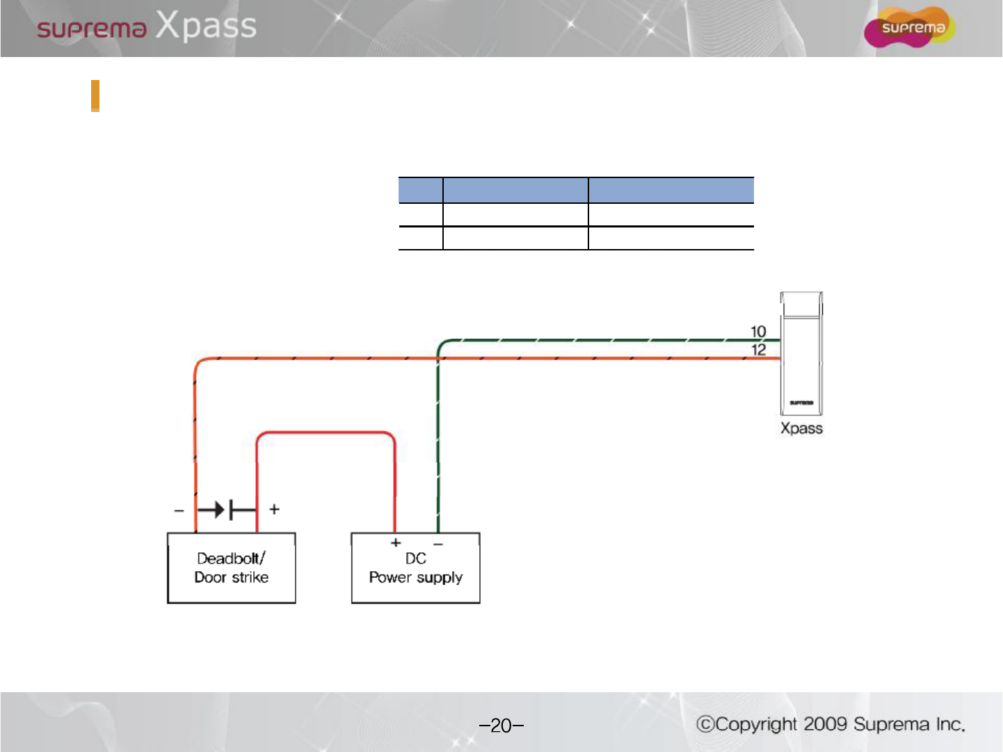
Relay Connection "Fail safe lock
Pin Pin Name Color
10 RLY COM Green (white string)
12 RLY NC Orange (black string)
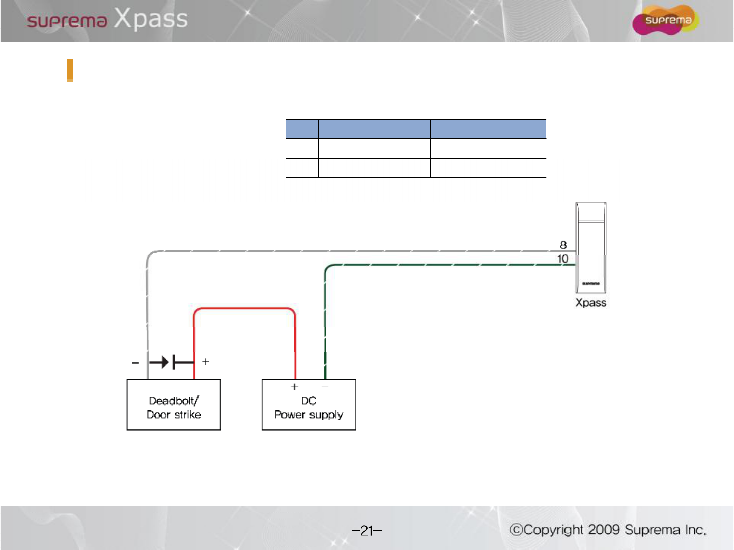
Relay Connection "Fail secure lock
Pin Pin Name Color
8RLY NO Gray (white string)
10 RLY COM Green (white string)
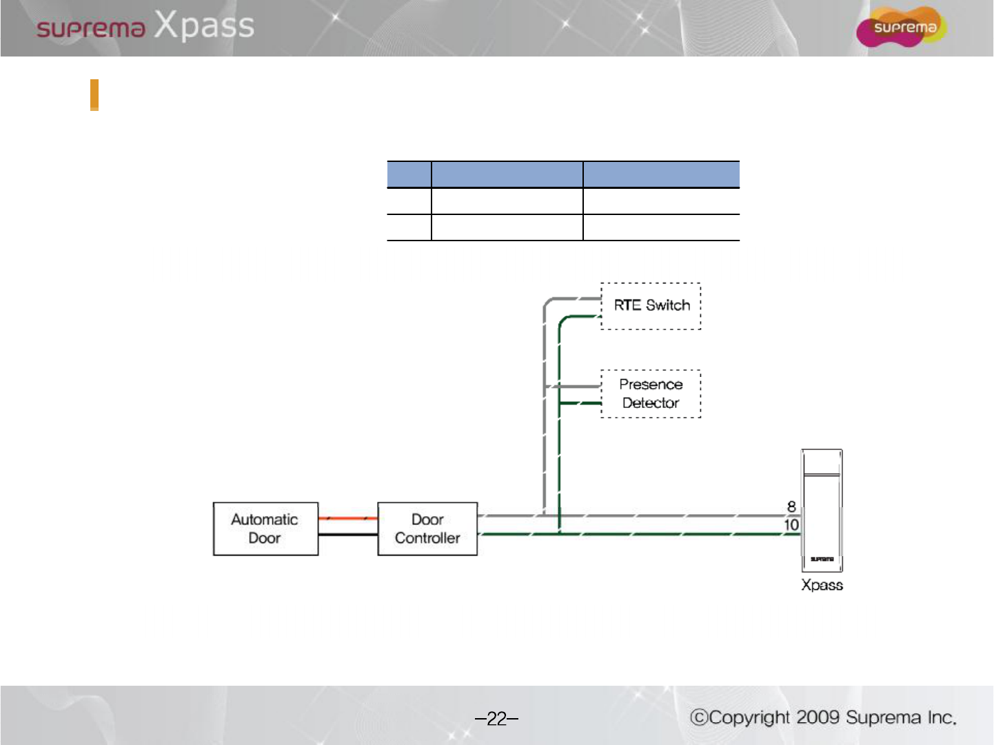
Relay Connection -Automatic door
Pin Pin Name Color
8RLY NO Gray (white string)
10 RLY COM Green (white string)
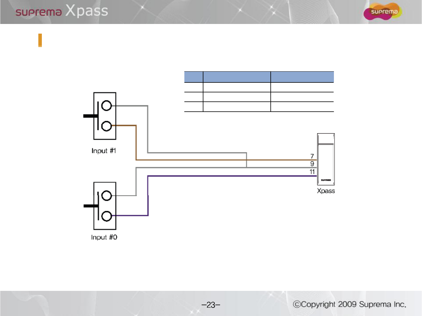
Digital Input Connection (Alarm, Emergency S/W)
Pin Pin Name Color
7IN 1 Brown
9IN GND Gray
11 IN 0 Purple
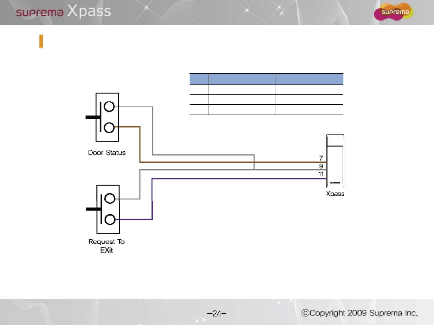
Digital Input Connection (RTE, Door sensor)
Pin Pin Name Color
7IN 1 Brown
9IN GND Gray
11 IN 0 Purple
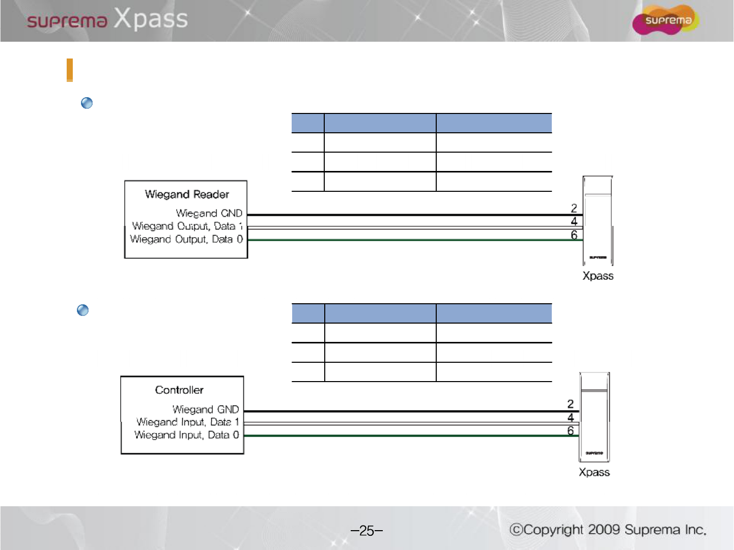
WiegandInput
WiegandInput/Output
WiegandOutput
Pin Pin Name Color
2WGD GND Black
4WGD D1 White
6WGD D0 Green
Pin Pin Name Color
2WGD GND Black
4WGD D1 White
6WGD D0 Green
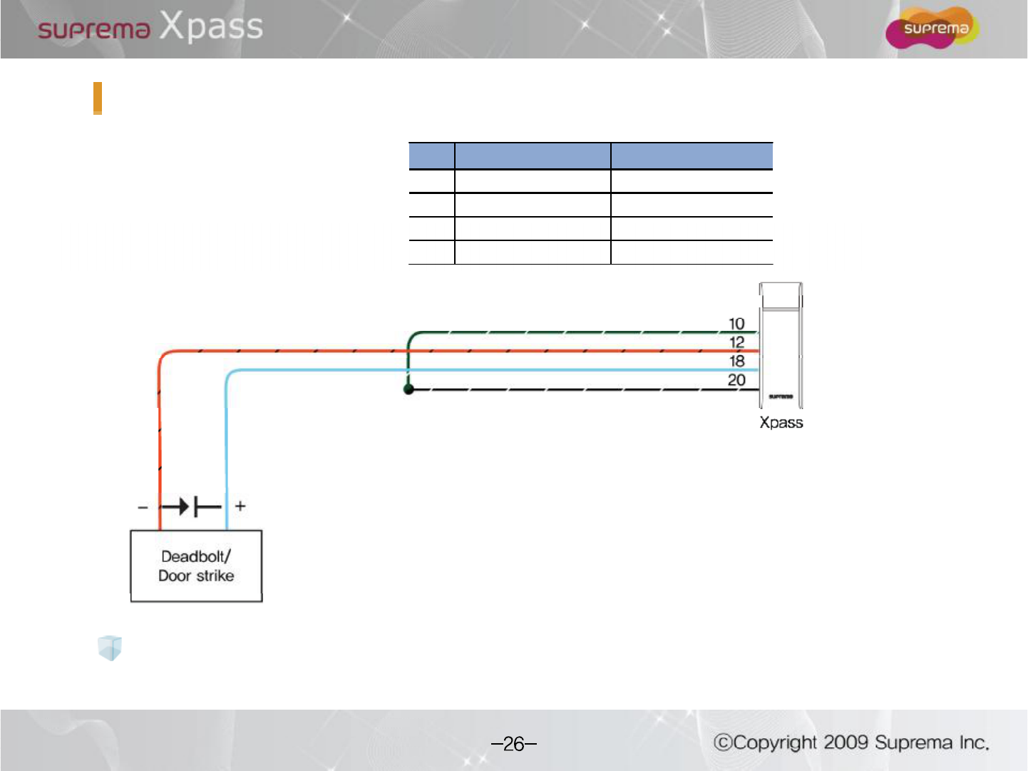
Output
Pin Pin Name Color
10 RLY COM Green (white string)
12 RLY NC Orange (black string)
18 PWR OUT + Light Blue
20 PWR OUT - Black (white string)
Caution : Max. 700mA is supplied using adapter for the external output.
Be careful to satisfy the power capacity in use.
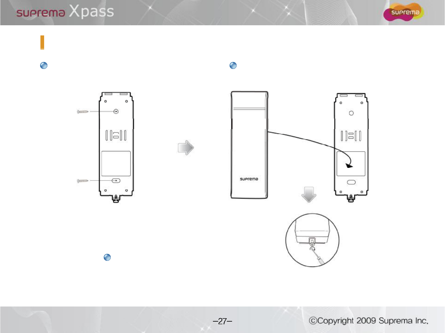
Fix wall mount bracket on a wall using
wall mounting screws
Hook Xpasson the wall mount bracket
Installation of Wall-mount Bracket
Fix Xpassand wall mounting bracket using
a wall mounting screw.
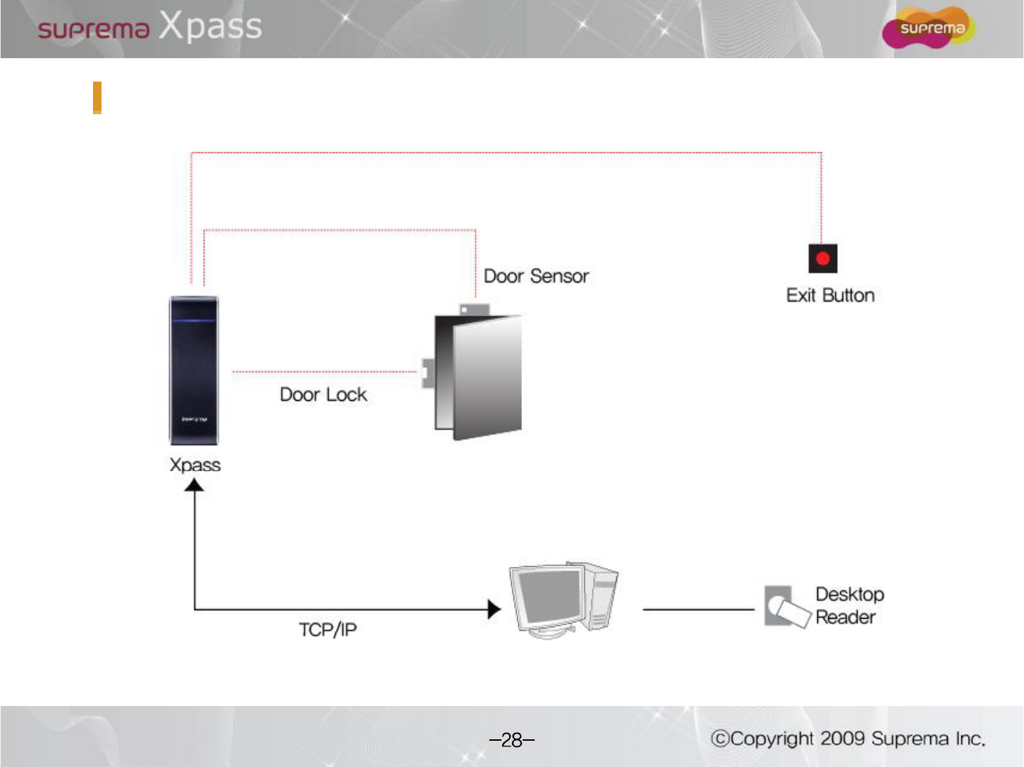
Installation Reference 1 -Stand alone
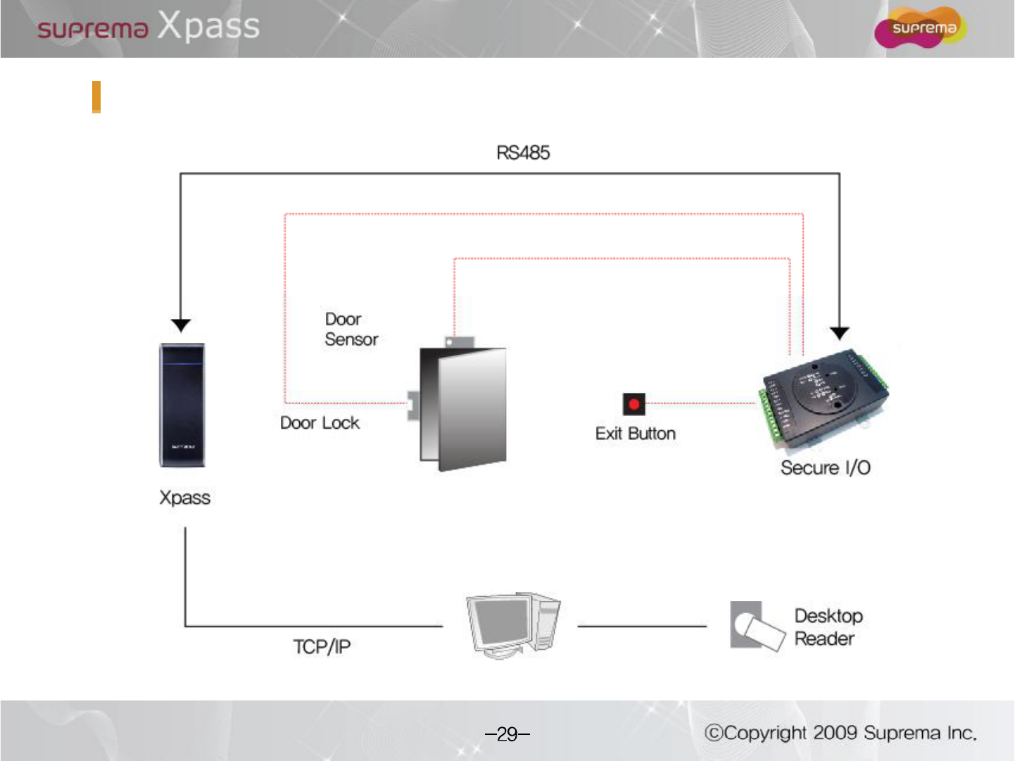
Installation Reference 2 "Standalone (Secure)
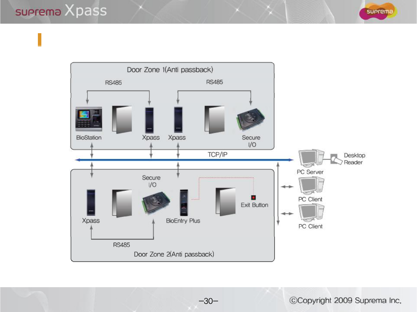
Installation Reference 3 "Network
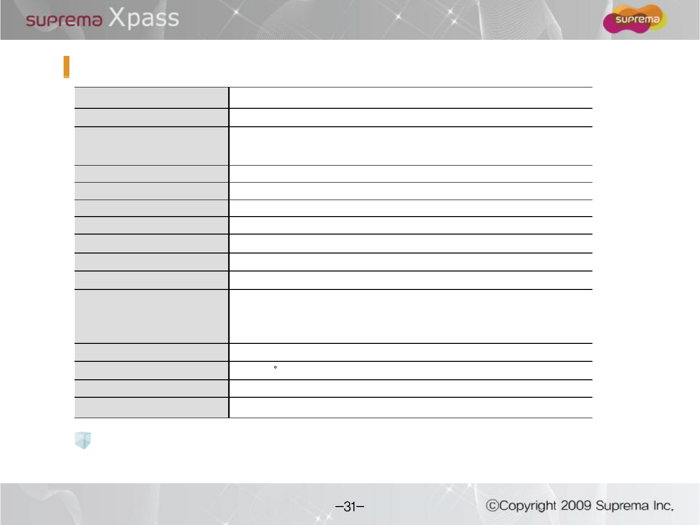
Specification
CPU 32 bit Micro-processor
Memory 8MB FLASH + 16MB SDRAM
RF Card
13.56 MHz Mifare(XPM)
125 KHz EM Prox(XPE)
125 KHz HID Prox(XPH)
User Capacity 40000 user
Log Capacity 50000 log
Network interfaces TCP/IP, RS485
IP Rate IP 65 class
Sound Multi-tone buzzer
LED Multi-color LED
RTC Lithium-ion rechargeable batteries
I/O
Relay x 1
Tamper x 1
Switch input x 2
Wiegandx 1
Power 12Vdc, POE
Operating Temperature -20 ~ 50 C
Size 45 x 130 x 27mm (W x H x D )
Certificates CE, FCC, KCC, IP65
It may be occurred the risk of explosionfor improper replacement of battery.
Please use the specified battery according to proper instruction.
Caution for RTC Battery
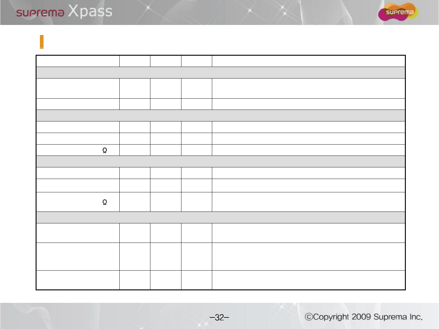
Min. Typ. Max. Notes
Power
Voltage (V) 10.8 12 13.2 Use regulated DC power adaptor only
Current (mA) - 140
Switch Input
VIH (V) - TBD -
VIL (V) - TBD
Pull-up resistance ( ) - 4.7k - The input ports are pulled up with 4.7k resistors
TTL/WiegandOutput
VOH (V) - 5 -
VOL (V) - 0.8 -
Pull-up resistance ( ) - 4.7k - The outputs ports are open drain type, pulled up with 4.7k
resistors internally
Relay
Switching capacity (A) - - 1
0.3
30V DC
125V AC
Switching power
(resistive) - -
30W
37.5V
A
DC
AC
Switching voltage (V) - - 110
125
DC
AC
Electrical Specification
Changes or modifications not expressly approved by the manufacturer
responsible for compliance could void the user s authority to operate the
equipment.
This device complies with part 15 of the FCC Rules. Operation issubject to the
following two conditions: (1) This device may not cause harmful interface, and
(2) this device must accept any interface received, including interference that
may cause undesired operation.
This equipment has been tested and found to comply with the limit of a Class B
digital device, pursuant to Part 15 of the FCC Rules. These limits are designed
to provide reasonable protection against harmful interference ina residential
installation. This equipment generates, user and can radiate radio frequency
energy and, if not installed and used in accordance with the instructions, may
cause harmful interference to radio communications.
However, there is no guarantee that interference will not occur in a particular
installation; if this equipment does cause harmful interference to radio or
television reception, which can be determined by turning the equipment off and
on, the user is encouraged to try to correct the interference byone or more the
following measures:
1. Reorient / Relocate the receiving antenna.
2. Increase the separation between the equipment and receiver.
3. Connect the equipment into an outlet on a circuit difference from that to
which the receiver is connected.
4. Consult the dealer or an experienced radio/TV technician for help
Caution
Warning
Information to User
FCC Rules