Suprema XSM Smart IP Access Terminal (XSM) User Manual
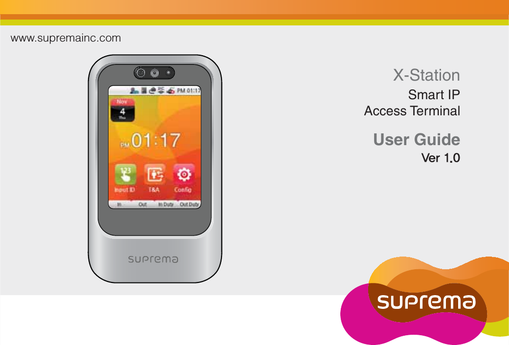
Suprema Inc. Smart IP Access Terminal (XSM)
UserManual.wiki
>
Suprema
>
XSM User Manual
Users Manual
Navigation menu
Upload a User Manual
Namespaces
Wiki Guide
HTML
PDF
Info
Views
User Manual
Discussion / Help
Navigation
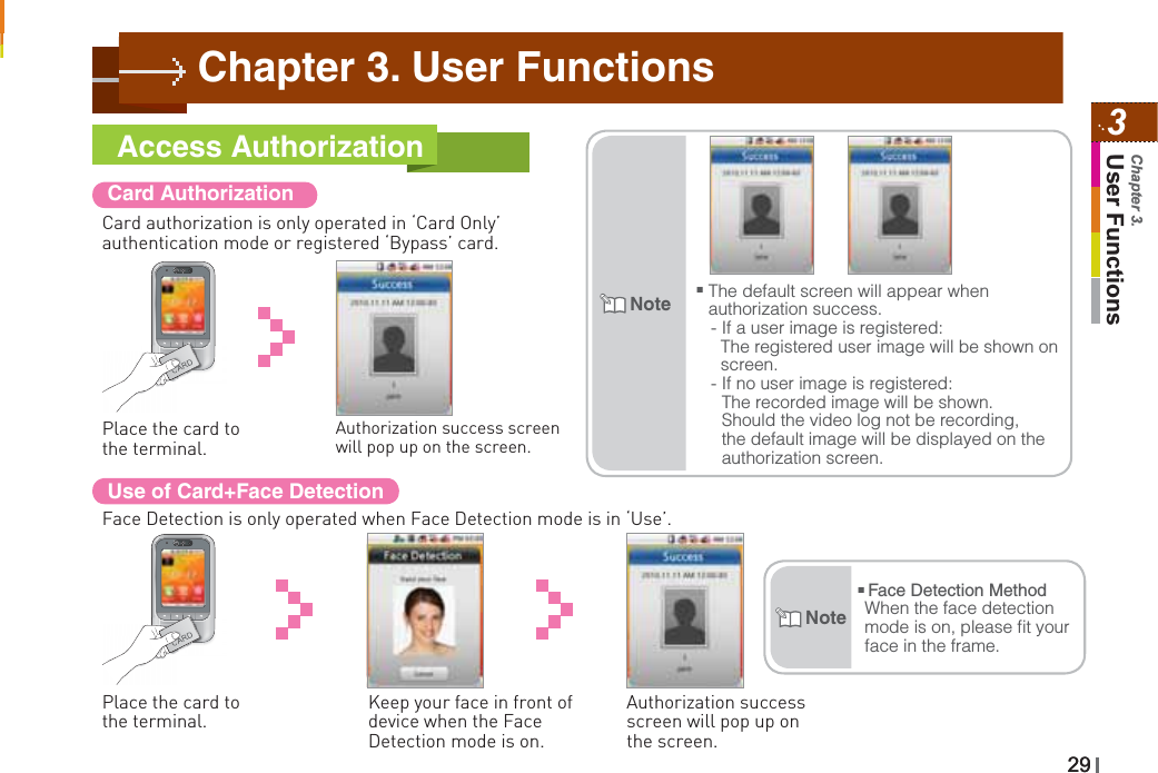
![111Before UseChapter 1.Authorization methodsAuthorize with a registered card.Card OnlyPlace a registered card and then, face detection authorization.Card+Face DetectionPlace a registered card, and then enter a password.Card+PasswordAuthorize with Card and password, and then face detection authorization.Card+Password+Face DetectionEnter a registered ID, and then enter a password.ID+PasswordAuthorize with ID and password, and then Face detection authorization. ID+Password+Face DetectionŶRefer to [Chapter 3. User Functions >1.Entrance Authorization] on page 28 for further explanations.Note](https://usermanual.wiki/Suprema/XSM/User-Guide-1390077-Page-11.png)
![30Use of Card+Password AuthorizationTo use password authorization, use Auth Mode with the ‘ID/Card+Password’ setup.Place the card to the terminal.Enter the password and press [OK].Authorization success screen will pop up on the screen.Use of Card+Password+Face Detection AuthorizationPlace the card to the terminal.Enter the password and press [OK].Capture your face image when the Face Detection screen appears.Authorization success screen will pop up on the screen.](https://usermanual.wiki/Suprema/XSM/User-Guide-1390077-Page-30.png)
![313User FunctionsChapter 3.Use of ID+Password AuthorizationTo use password authorization, use Auth Mode with the ‘ID/Card+Password’ setup.Press [Input ID] on the main screen.Enter your ID on the ID screen and then press [OK].Enter your password and then press [OK].Use of ID+Password+Face Detection AuthorizationPress [Input ID] on the main screen.Enter your password and then press [OK].Capture your face image when the Face Detection screen appears.Authorization success screen will pop up on the screen.Authorizationsuccess screen will pop up on the screen.Enter your ID on the ID screen and then press [OK].](https://usermanual.wiki/Suprema/XSM/User-Guide-1390077-Page-31.png)
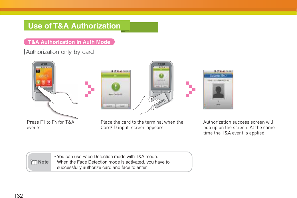
![333User FunctionsChapter 3.Press F1 to F4 for each of the T&A events.Place the card to the terminal.Press F1 to F4 for each of the T&A events.Press [Input ID]. Enter your password and then press [OK].Authorization success screen will pop up on the screen. At the same time the T&A event is applied.Enter your password and then press [OK].Authorization success screen will pop up on the screen. At the same time the T&A event is applied.Enter your ID on the ID screen and then press [OK].*%$BSE1BTTXPSE"VUIPSJ[BUJPO*%1BTTXPSE"VUIPSJ[BUJPO](https://usermanual.wiki/Suprema/XSM/User-Guide-1390077-Page-33.png)
![34T&A ModeIf you set up the T&A mode to [Manual], users must press the F1 to F4 key every time you enter or leave to record T&A events.If you set up the T&A mode to [Manual Fix], the device will remain in the previous T&A events until a different T&A key is pressed.If you set the T&A mode to [Disabled], device is disable the T&A function and only operate access control function. If you set up the T&A mode to [Auto], users do not have to select a T&A event. The device will automatically change T&A events to correspond with the functions specified for a time period. Users can select different T&A events by pressing the function key. If you set up the T&A mode to [Fixed], the device will perform only the specified T&A events. User is not able to select a different T&A key. *User can change automatic time period and T&A event in the BioStar.](https://usermanual.wiki/Suprema/XSM/User-Guide-1390077-Page-34.png)
![353User FunctionsChapter 3.Extra T&A EventsExtra T&A events screen.Singular Entrance /T&A Records CheckSelect [Config] on the main screen.Place your card to the terminal and press [Input ID].If the authorization was successful, you can check your access/T&A records.Press [T&A] on the main screen to select extra T&A events.ⶮ#BTJD5"FWFOUT'_'Ɣ*O"SSJWFBUXPSLƔ0VU-FBWFBGUFSXPSLƔ*O%VUZ3FUVSOEVSJOHXPSLƔ0VU%VUZ-FBWFUFNQPSBSJMZEVSJOHXPSL:PVDBODIBOHFUIFCBTJD5"FWFOUTⶮ&YUSB5"FWFOUT:PVDBOTFUUIFFYUSB5"FWFOUTCFTJEFTPGCBTJD5"FWFOUT:PVDBODSFBUFVQUP5"FWFOUTJOUIF#JP4UBS&YBNQMF"SSJWJOHBUXPSLBGUFSPGGTJUFXPSLMFBWJOHXPSLBGUFSPGGTJUFXPSLSFUVSOJOHBGUFSPGGTJUFXPSLNPSOJOHCSFBLBGUFSOPPOCSFBL](https://usermanual.wiki/Suprema/XSM/User-Guide-1390077-Page-35.png)
![Registering an AdminThere is no registered user data in the new product. Please register the administrator immediately after the first installation. The Admin enables to add/delete user, and configure device setting.Press [Config] on the main screen.Select [Enroll User].Select [User]. Check the [Admin] box if you want to enter an Admin.Input DataTouch the picture to enter personal data. The data will be used when authorization is successful. The picture can be saved with BioStar.Enter a password. Enter the name. (You can only use English characters) Place the card to the reader. The card ID will read and register the card data.Enter the user ID.The user ID can be created numbers 1 to 4294967295.User ID Card ID Name Password FaceChapter 4. Admin Menu3737374Admin MenuChapter 4.](https://usermanual.wiki/Suprema/XSM/User-Guide-1390077-Page-37.png)
![38ŶSince anyone can use the Admin Menu if no Admin is registered, you must register an Admin first.Waring͒NoteRegistering an Admin (continued)Set up a [Bypass Card] if you need one.Set up a Private Auth and Access Group if you need them.Enroll success screen will pop up on the screen.Press [Add] to finish the Admin registration.ŶUsers who are registered with a ‘Bypass Card’ will be authorized by bypass regardless of the Auth Mode.Users who are registered with the ‘Private Auth mode’ will have priority in the terminal’s Auth mode and be authorized in Private Auth.The ‘Access Group’ determines whether a user can enter or not. You can select an Access Group within the BioStar software for the relevant terminal.NoteŶYou have to enter either card or password to make a registration.The T&A button on the lower part of the screen has the same function as the F1~F4 keys.Instead of pressing [Prev]/[Home], you can also use F3/F4.](https://usermanual.wiki/Suprema/XSM/User-Guide-1390077-Page-38.png)
![394Admin MenuChapter 4.Entering the Admin MenuPress [Config] on the main screen.The Admin Menu will appear on screen.Enter the password if necessary and press [OK].The Admin Menu will appear.Enter your card or ID.](https://usermanual.wiki/Suprema/XSM/User-Guide-1390077-Page-39.png)
![414Admin MenuChapter 4.UserRegistering an UserRegistration at the Terminal (when using a CSN Card)If you use a CSN Card, select CSN Card under [Mode>Task>Card mode].Press [Config] on the main screen.Select [Enroll User].Select [User]. Do not check the box [Admin] when registering a user.Enter the user ID. The user ID can be created numbers 1 to 4294967295.Enter the name. (You can only use English characters)Place the card to the reader. The card ID will read and register the card data.Record a face and press [OK]. The face will appear each time authorization was successful.](https://usermanual.wiki/Suprema/XSM/User-Guide-1390077-Page-41.png)
![42Registering an User (continued)Enter the password. Setup [Bypass Card] option, press [Ļ] in the bottom of the screen.Setup [Private Auth] mode and [Access Group] ,press [Add] or F4.Enroll success screen will pop up on the screen.ŶUsers who are registered with a ‘Bypass Card’ will be authorized by bypass regardless of the Auth Mode.Users who are registered with the ‘Private Auth mode’ will have priority in the terminal’s Auth mode and be authorized in Private Auth.The ‘Access Group’ determines whether a user can enter or not. You can select an Access Group within the BioStar software for the relevant terminal.Note](https://usermanual.wiki/Suprema/XSM/User-Guide-1390077-Page-42.png)
![434Admin MenuChapter 4.Edit UserSelect [User]. Select the user from the user list.Select [Edit User]. Press [Add] or F4 after changing the user data.ŶIf you check the right hand box in the user list and press [Delete], you can delete the selected user.NoteEnroll success screen will pop up on the screen.](https://usermanual.wiki/Suprema/XSM/User-Guide-1390077-Page-43.png)
![44User SearchSelect [User]. Select [Search by ID] and press [OK].Select [Search]. Enter the ID number and press [OK]. The corresponding ID search results will appear.Search by User IDSearch by NameSelect [User]. Select [Search by Name] and press [OK].Select [Search]. Enter the name and press [OK]. The corresponding usernamesstarting with those letters will appear.](https://usermanual.wiki/Suprema/XSM/User-Guide-1390077-Page-44.png)
![454Admin MenuChapter 4.Checking the Registered User InfoPress [OK] to return to the previous screen.Select [User]. Select [Enrolled user Info].ŶYou can register a maximum of 200,000 users.You can save up to 5,000 user images.NoteSelect [User]. Select [Search by CNS] and press [OK].Select [Search]. Place the CSN Card to the card reader. The search results will be shown in the window.Searching by CSN Card](https://usermanual.wiki/Suprema/XSM/User-Guide-1390077-Page-45.png)
![46Enter the user ID to be deleted and press [OK].Select [User]. Check the box next to the user to be deleted. Press [Delete] in the lower corner, or F4.Select [Search]. By pressing [OK] the selected user will be deleted.Check the box next to the users to be deleted. Press [Delete] in the lower corner, or F4.Select [User]. By pressing [OK] the selected users will be deleted.Select [Edit User].Deleting one userDeleting several usersŶYou cannot restore user data that is not stored in the BioStar database.Attention͒](https://usermanual.wiki/Suprema/XSM/User-Guide-1390077-Page-46.png)
![474Admin MenuChapter 4.Select [User]. Click [Delete All Users].Press [OK] in the Delete window to erase all user data from the terminal.ŶYou cannot restore user data that is not stored in the BioStar database.Attention͒Delete All Users](https://usermanual.wiki/Suprema/XSM/User-Guide-1390077-Page-47.png)
![48Registering Data Card (When Using a Data Card)If you use a Data Card, go to [Mode>Operation>Card Mode] and select Data Card.If a Data Card is used, the user data will not be saved on the terminal and you need to manage the user data separately.Select [Enroll Data Card].Press [Config] on the main screen.Enter the user data when the input screen appears.Select [User].Enter the password.Enter user ID. Select [Admin] if necessary.Enter the name. (You can only enter Latin letters.)](https://usermanual.wiki/Suprema/XSM/User-Guide-1390077-Page-48.png)
![494Admin MenuChapter 4.User Registration (continued)Place the card to the reader.Set up a [Bypass Card] and an Access Group if needed.Data card enroll success screen will pop up on the screen.After entering all user data, press [Add].ŶUsers who are registered with a ‘Bypass Card’ will be authorized by bypass regardless of the Auth Mode.The ‘Access Group’ determines whether a user can enter or not. You can select an Access Group within the BioStar software for the relevant terminal.NoteŶ You cannot use CSN Card and Data Card at the same time.Attention͒](https://usermanual.wiki/Suprema/XSM/User-Guide-1390077-Page-49.png)
![50Formatting Data CardsPlace the Data Card to the reader.Select [User]. Format success screen will pop up on the screen.Select [Format Data Card].All saved data on Data Cards will be deleted.](https://usermanual.wiki/Suprema/XSM/User-Guide-1390077-Page-50.png)
![514Admin MenuChapter 4.TCP/IP SetupEnable to setup TCP/IP for connecting the terminal and BioStar.Select [TCP/IP]. Enter port and IP Address, etc., press [Ļ] to move to the next screen.PPress [Prev] or [Home] after finishing the setup and the changes will be activated.Ɣ Use TCP/IP: Sets up the use of TCP/IP. If you use Ethernet with Zone, TCP/IP has to always have the setting ‘USE’. Ɣ Port: Assigns the terminal TCP/IP port. The default value is ‘1470’.Ɣ Max Conn.: Sets the number of BioStar that can be connected to the terminal. (Set value: 1,4,6,8 and 16)Ɣ DHCP: Sets whether or not to use DHCP protocol (Set values; Enabled / Disabled). ƔIP Address: Enter the IP address when adopting a fixed IP instead of DHCP protocol. Ask your network administrator for the IP address. The default value is 127.0.0.1.ƔGateway: Enter the gateway address when adopting a fixed IP instead of DHCP protocol. Ask your network administrator for the address.ƔSubnet: Enter the Subnet Mask address when adopting a fixed IP instead of DHCP protocol, Ask your network administrator for the address.Network Setup](https://usermanual.wiki/Suprema/XSM/User-Guide-1390077-Page-51.png)
![52Server SetupThe terminal enables to communicate with BioStar server or SDK application server. Configure the IP address and ports of the server to connect to the terminal.Select [Server]. Setup the use of server, IP, and port press [Prev] or [Home] to activate the settings.ƔServer: Set up the use of the server.ƔServer IP: Enter the server IP. ƔPort: Enter the server port.](https://usermanual.wiki/Suprema/XSM/User-Guide-1390077-Page-52.png)
![534Admin MenuChapter 4.Serial Communication SetupSet the serial communication. The serial communication uses RS485 and can be connected with the PC or SIO.Select [Serial]. Set up RS485-PC, and RS485-NET.ƔRS485-PC: Set the network speed between the terminal and a PC in RS485 communication. (Set values: 9600/19200/57600/115200)ƔRS485-NET: Set the communication with Secure I/O and other terminals. (Set value: Disabled, Net-Slave, Net-Host)RS485 mode enables to communicate between a server terminal and up to 7 salve terminals. - Net-Host: Sets the terminal as host. - Net-Slave: Sets the terminal as slave.](https://usermanual.wiki/Suprema/XSM/User-Guide-1390077-Page-53.png)
![54Task ManagementModeSelect [Mode]. Press [Operation]. Set up Auth Mode, Face Detection, Card Mode, etc.ƔCard Only: Users input only cards for authentication. In this mode, the card type must be select on the [Card Mode]. (Set values: Always/No Time)ƔID/Card+Password: Users input ID/Card and Password consecutively for authentication.ƔFace Detection: Set the Face Detection mode. If it is activated, you have to successfully pass Face Detection after you enter your card or password to gain authorization. (Settings: Always/ No Time)ƔDual: Dual Authentication needs consecutive authentications from two different users within 15 seconds for high security. After 15 seconds, the first authorization will become invalid and you have to do both authorizations over again. (Settings: Always/Never)Attention͒ŶIf device setting is [Card Only] - [No Time] and [ID/Card+ password] - [No Time] at the same time, users can only authorize by Bypass Card.(You cannot enter the Admin Menu with authorization with ID/Card.>You have to register a Bypass Card when registering user.](https://usermanual.wiki/Suprema/XSM/User-Guide-1390077-Page-54.png)
![554Admin MenuChapter 4.T&A ManagementYou can set up a T&A for the terminal.Select [T&A]. Select [T&A]. Press [OK] after selecting a T&A mode.ŶRefer to the detail T&A mode [Chapter 3.User Functions >2.T&A Authorization>T&A mode] for details. (page 33)NoteCard Mode: Set the card type used on the terminal. (Settings: Use CSN/Use Data Card/Not Use) -CSN Card: After the terminal reads the card’s id number and saves it, every time the terminal compares the card id number successfully with the saved number, authorization will be granted. -Data Card: The user ID and other data will be saved on the card, and if the card is touched to the terminal, it will read the card’s data.ƔServer Matching: enable this setting to perform card ID matching at the BioStar server, instead of the device. When this mode is enabled, the devices will send the card ID to the server to verify a match. This mode is useful when you have more users than can be downloaded to a device or user’s information cannot be distributed due to security concerns.ƔMatching timeout: Sets up the waiting time for Server Matching and Face Detection. (Settings: 5sec/10sec/15sec/20sec/30sec)In case there is no answer from the server during Matching Time or the face cannot be detected, the authorization will fail.Ɣ Individual Auth Mode: Sets up individual Auth Modes.Mode (Continue)](https://usermanual.wiki/Suprema/XSM/User-Guide-1390077-Page-55.png)
![56T&A eventYou can check automatic time and activation for T&A events with F1~F4 or the T&A event button (EXT 01~12) through BioStar. T&A events can only be set up through BioStar. On the terminal, the events can only be checked.Select [T&A event]. Use [ź]/ [Ÿ] to check the settings on BioStar.Camera EventIn case of a Camera Event, the camera will start recording when the event begins and then save the video log. You can only set up Camera Events through BioStar. On the terminal, the events can only be checked.Select [Camera Event]. Here you can check the camera event.](https://usermanual.wiki/Suprema/XSM/User-Guide-1390077-Page-56.png)
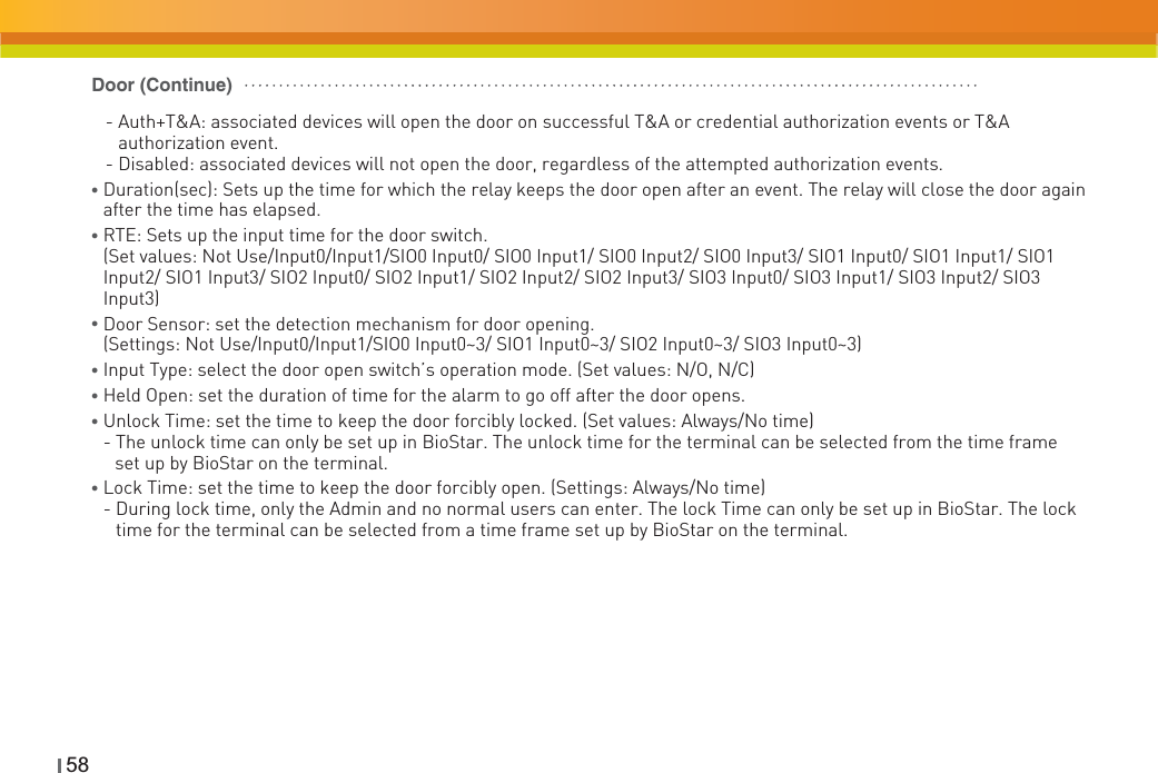
![574Admin MenuChapter 4.DeviceDoorPress [Device]. Press [Door]. Enter the settings.ƔRelay: Select replay to open the door on authentication. (Settings: Not Use/Internal Relay/External Relay 0/External Relay 1/SIO0 Relay0/SIO0 Relay1/SIO1 Relay0/SIO1 Relay1/SIO2 Relay0/SIO2 Relay1/SIO3 Relay0/SIO3 Relay1)ƔDriven by: select type of event that associated devices will activate the trigger to open the door (Settings: All events/Auth/T&A/Auth+T&A/T&A event/Disabled)- All events: associated devices will open the door on any successful authorization events.- Auth: associated devices will open the door only on successful credential authorization events.- T&A: associated devices will open the door only on successful T&A authorization events.](https://usermanual.wiki/Suprema/XSM/User-Guide-1390077-Page-57.png)
![594Admin MenuChapter 4.Time SetupYou can set up the time that appears on the terminal. You have to set up the time to receive accurate log data.Press [Device]. Press [Time].Ɣ Date: Enter the current date. Use ( YYYYMMDD) (+)/(-) to enter the date.Ɣ Time: Enter the current time. Use ( hh:mm:ss) (+)/(-) to enter the time.ƔTime Sync: You can use Time Sync in the server mode. The terminal’s time will be synchronized with the server time. The time will be adjusted once every hour and only if the time difference between terminal and server more than 5 seconds.Set up data, time, and time sync.](https://usermanual.wiki/Suprema/XSM/User-Guide-1390077-Page-59.png)
![60Device InfoPress [Device]. Select [Device Info]. Check device ID, FW version, etc.Memory InfoPress [Device]. Select [Memory Info.]. Check the present status of the terminal’s memory.](https://usermanual.wiki/Suprema/XSM/User-Guide-1390077-Page-60.png)
![614Admin MenuChapter 4.CalibrationPress [Device]. Select [Calibration]. Press the cross that appears on the screen. If the cross moves, follow it on the screen. As soon as calibration is finished, the cross will disappear.Calibrationsuccess screen will pop up on the screen.](https://usermanual.wiki/Suprema/XSM/User-Guide-1390077-Page-61.png)
![62Device ResetPress [Device]. Select [Reset]. Press [OK] to restart the terminal.Factory DefaultPress [Device]. Press [Ļ] in the lower part of the display to move to the next screen.Select [Factory Default].Press [OK] to reset all settings to factory default value.ŶPlease be aware that the factory default setting means that all wallpapers, sound effects, notices, etc. you have downloaded from BioStar will be deleted. However, even if you execute factory default the registered user data and log data will not be deleted.Waring͒](https://usermanual.wiki/Suprema/XSM/User-Guide-1390077-Page-62.png)
![634Admin MenuChapter 4.Display & SoundClick [Display]. Enter theme, volume, etc.ƔTheme: Select a theme for the screen background.(Selection: Theme 1/Theme 2/Theme 3)](https://usermanual.wiki/Suprema/XSM/User-Guide-1390077-Page-63.png)

![654Admin MenuChapter 4.Log ManagementChecking the Log ListYou can check the terminal’s normal log and the video log records.Checking the Normal LogClick [Log]. Select [Log List]. Click on a savedlog record. You can check a normal log by clicking on the log item. Checking the Video LogClick [Log]. Select [Log List]. Here you can see the saved log records. If you click on log items with , you can see the video log.](https://usermanual.wiki/Suprema/XSM/User-Guide-1390077-Page-65.png)
![Delete All LogsClick [Log]. Select [Delete]. If you click [OK], all saved logs will be deleted.Delete success screen will pop up on the screen.Check Log InfoŶDevice enables to store up to maximum of 1,000,000 normal logs and 5,000 video logs.NoteClick [Log]. Select [Log Info.]. Here you can check the logs that are presently saved on the terminal. Click [OK] to return to the previous screen.66](https://usermanual.wiki/Suprema/XSM/User-Guide-1390077-Page-66.png)